master of technology - university of tasmania
TRANSCRIPT
SOURCE ROUTING AND TRANSPARENT BRIDGING
INTERCONNECTIONS AND
THEIR PERFORMANCES
A thesis submitted to the University of Tasmania in partial fulfilment of the requirement
for the degree of
Master of Technology
ILHAM SAWA'UN
Department of Electrical and Electronic Engineering
University of Tasmania
Hobart
December 1991
I t

ABSTRACT
The interconnection between IEEE 802.5 and IEEE 802.3 LANs is carried out at layer 2 of OSI model or precisely at Medium Access Control level. Since these two LANs have many different characteristics, and are incompatible so that interoperability becomes a problem during their interconnection. IEEE 802.5 LANs use a strategy which is called Source Routing for their interconnection whereas IEEE 802.3 LANs use different strategy which
is called Transparent Bridging. To overcome the problem of internetworking of these two different LANs, IEEE proses a new standard for routing strategy
which is called Source Routing Transparent (SRT). This thesis studies the
problems arising from Source Routing and Transparent bridging interconnections and discuss how SRT address the problems of Source Routing and Transparent Bridging. A mathematical analysis is done to analyze the performance of Source Routing and Transparent Bridging. SIMSCRIPT simulation programs are developed to conform with the mathematical analysis. The results of these two approaches agree with each other. Broadly speaking, the performance of Source Routing is deterministic whereas Transparent Bridging is random due to collision of frames at high utilization.

ACKNOWLEDGEMENT
I would like to thank for all people who help in the preparation of
this thesis. In particular I wish to acknowledge :
1. Professor D.T. Nguyen, as M Tech program director, for his
direction and support in preparing and improving this thesis.
2. Dr. David J.H. Lewis, as project supervisor, who has provided
valuable guidance for the development of this thesis.
3. Peter Atkinson, advisory SE of IBM Australia, who has given
me the specification of this project thesis and supported me with many
references to start with.
4. The Indonesian government for giving me the opportunity to
undertake this M Tech course.
5. All postgraduate students especially M Tech students who have
helped me in the development of this thesis.
Finally, I wish to thank for my family and my girl friend for their
support and encouragement during my study here.
Hobart, December 1991
TABLE OF CONTENTS
ABSTRACT
ACKNOWLEDGEMENT ii
TABLE OF CONTENTS iii
LIST OF FIGURES
GLOSSARY vi
Chapter
1. : INTRODUCTION 1
2 : LAN BRIDGES 4
2.1 IEEE 802 STANDARDS AND OSI MODEL 4
2.2 TOKEN RING NETWORKS 5
2. 2.1 Introduction 5 2.2. 2 MAC Frame Format 6
2. 2. 3 Source Routing 8
2. 3 802.3 LANs 11
• 2.3. 1 Introduction 11
2. 3. 2 IEEE 802.3 MAC Frame 11
2. 3. 3 Transparent Bridging 12
2. 4 Source Routing and Transparent Bridging Comparison 17
2.5 BRIDGE PROBLEM OF 802.3 AND 802.5 LANs 18
3: SOURCE ROUTING TRANSPARENT (SRT) BRIDGE 21
3.1 INTRODUCTION 21
3.2 MAC SERVICE 23
3.3 PRINCIPLES OF OPERATION 26

3. 4 THE SPANNING TREE ALGORITHM AND PROTOCOL 29
3.5 BRIDGE MANAGEMENT 32
3.6 DISCUSSION 34
4: PERFORMANCE ANALYSIS 38
4.1 PERFORMANCE ANALYSIS FOR SOURCE ROUTING 38
4. 1. 1 Mathematical Analysis 38
4. 1. 2 Simulation of Token Ring 42
4. 1.3 Simulation of Source Routing 42
4.2 PERFORMANCE ANALYSIS OF 802.3 LANs 44
4. 2. 1 Mathematical Analysis 44
4. 2. 2 Simulation of IEEE 802.3 LAN 54 4. 2. 3 Simulation for Transparent Bridging 55
4. 3 DISCUSSION 57
5: CONCLUSION 59
REFERENCES 62
APPENDICES 64
1. Simulation Results for one Ring 64
2. SIMSCRIPT Programs for one Ring 64
3. Simulation Results for Source Routing 67
4. SIMSCRIPT Programs for Source Routing 68
5. Simulation Results for CSMA/CD LAN 76
6. SIMSCRIPT Programs for CSMA/CD LAN 76
7. Simulation Results for Transparent Bridging 80
8. SIMSCRIPT Programs for Transparent Bridging 81
iv

LIST OF FIGURES
FIGURE 2.1
FIGURE 2.2
FIGURE 2.3
FIGURE 2.4
FIGURE 2.5
FIGURE 2.6
FIGURE 2.7
FIGURE 2.8
FIGURE 2.9
FIGURE 2.10
FIGURE 2.11
FIGURE 3.1
FIGURE 3.2
FIGURE 3.3
FIGURE 3.4
FIGURE 4. 1
FIGURE 4.2
FIGURE 4.3
FIGURE 4.4
FIGURE 4.5
FIGURE 4.6
FIGURE 4.7
FIGURE 4.8
FIGURE 4. 9
FIGURE 4.10
FIGURE 4.11
FIGURE 4 .12
FIGURE 4.13
FIGURE 4.14
FIGURE 4.15
FIGURE 4.16
FIGURE 4.17
: IEEE 802 STANDARDS AND OS! MODEL
: FRAME AND TOKEN FORMAT
: FORMAT AND CONTENT OF SD, AC AND FC
: ROUTING INFORMATION FIELD
: IEEE 8023 MAC FRAME FORMAT
: A TYPICAL NETWORK
: THE OPERATION OF BRIDGE
: A TYP ICAL LAN CONFIGURATION
: BRIDGE FORWARDING & LEARNING FLOW
: PARALLEL BRIDGES
: DEVELOPMENT OF A SPANNING TREE
: BRIDGE DIAGRAM
: SRT BRIDGE OPERATION
: BRIDGED LANS
: SPANNING TREE TOPOLOGY
: THREE CONNECTED LAN SEGMENTS
: TOKEN RING QUEUING SYSTEM
: DELAY VS THROUGHPUT
: DELAY & NUMBER OF FRAMES IN BUFFER
: DELAY VS THROUGHPUT
: PERCENTAGES OF TRAFFIC DESTINATION : CSMA/CD REPRESENTATION
: RESCHEDULING TRANSMISSION : DETECTION TIME
: TRANSMISSION SCHEDULE
: UTILIZATION VS DELAY (CSMA/CD)
: UTILIZATION VS DELAY (a = 0.1)
: SIMULATION RESULTS FOR a=0.01 54
: SIMULATION RESULTS FOR a = 0.1 55 : BRIDGED LANs CONFIGURATION 56
: VARIOUS PACKET DELAYS VS UTILIZATION 57
: PERFORMANCE COMPARISON 58
4
6
7
7
11
13
13
15
CHART 16
17
17
22
28
31
32
38
39
41
VS THROUGHPUT 42
43
43
45
45
45
47
53
53

GLOSSARY
AC. Access Control. A particular field in MAC frame.
Bandwidth. The difference between the limiting frequencies of• a
continuous frequency spectrum.
Baseband. Transmission of signal without modulation. In a baseband local area network, digital signals ('O's and l's) are inserted directly
onto the cable as voltage pulses. The entire spectrum of the cable is consumed by the signal. This scheme does not allow frequency-
division multiplexing.
Broadband. The use of coaxial cable for providing data transfer by means of analog (radio-frequency) signals. Digital signals are passed through a modem and transmitted over one of the frequency bands of the
cable.
Broadcast. The simultaneous transmission of data to a number of station.
BPDU. Bridge Protocol Data Unit. A protocol data unit which is related to
bridge.
Bridge. A device that links two local area networks. It accepts packets
from network addressed to devices on the other, buffer them, and
retransmits them to other network.
Coaxial Cable. A cable consisting of one conductor, usually a small copper tube or wire, within and insulated from another conductor of larger
diameter, usually copper tubing or copper braid.
Collision. A condition in which two packets are being transmitted over a
medium at the same time. Their interference makes both
unintelligible.
vi

Connectionless. A system for exchanging data in an unplanned fashion
and without prior coordination.
Connection-oriented. A system for exchanging data in which a logical
connection is established between the endpoints.
CSMA. Carrier Sense Multiple Access. A media access control technique for multiple-access transmission media. A station wishing to transmit first senses the medium and transmits only if the medium is idle.
CSMA/CD. Carrier Sense Multiple Access with Collision Detection. A
refinement of CSMA in which a station ceases transmission if it detects a collision.
CRC. Cyclic Redundancy Check. An error detecting code in which the code is the remainder resulting from dividing the bits to be checked
by a predetermined binary number.
DA. Destination Address. The address of destination station.
Data Link Layer. Layer 2 of the OSI model. Converts unreliable
transmission channel into reliable one.
ED. Ending Delimeter. A special field of MAC frame.
Encapsulation. The addition of control information by a protocol entity to data obtained from a protocol user.
Error rate. The ratio of the number of data units in error to the total
number of data units.
PC. Frame Control. A field of MAC frame. This field defines the type of
the frame and certain MAC and information frame function.
FCS. Frame Check Sequence. An error-detecting code inserted as a field
in a block of data to be transmitted. The code serves to check for errors upon reception of the data.
FDDI. Fibre Distributed Data Interface. FDDI is a standard for high-speed
ring LAN. It employs the Token ring algorithm.
vii

FIFO. First In First Out. A queuing system where the first incoming
frame will be firstly served.
FS. Frame Status. A field in MAC frame.
Gateway. A device that connects two system, especially if the systems use
different protocols. For example,. a gateway is used to connect two
independent local networks, or to connect a local network to a long-
haul network.
Hosts. In any network there exists a collection of machines intended for
running user (i.e. application) program. It is common to call these
machines Hosts.
IEEE. Institute Electrical and Electronic Engineering.
ISO. International Standard Organization.
Internetworking. Communication among devices across multiple
networks.
LAN. Local Area Network. A general-purpose local network that can
serve a variety of devices. Typically used for terminals,
microcomputers and minicomputers.
LLC. Logical Link Control. A sub layer of Data Link Layer.
LPDU. Link Protocol Data Unit.
MAC. Medium Access Control. For broadcast networks, the method of
determining which device has access to the transmission medium
at any time. CSMA/CD and Token are common access methods.
This is a sub layer of Data Link Layer.
Mbps. Mega bits per second.
M/M/1. A queuing system with Exponential interarrival time, and
Exponential service time and one server.
viii

Optical Fibre. A thin filament of glass or other transparent material through
which a signal-encoded light beam may be transmitted by means of
total internal reflection.
OSI. Open System Interconnection. A communication model defined by
ISO.
PDF. Probability Density Function.
Physical Layer. Layer 1 of the OSI model. Concerned with the electrical, mechanical, and timing aspects of signal transmission over a
medium.
Protocol. A set of rules that govern the operation of functional units to
achieve communication.
Protocol Data Unit. A block of data exchanged between two entities via a
protocol.
RI. Routing Information. Routing information field contains a series of LAN and bridge numbers to be passed when transmitting a frame in Source routing method.
RH. Routing Information Indicator. This information indicates whether the frame contains Routing information field or not.
Ring. A local network topology in which stations are attached to repeaters
connected in a closed loop. Data are transmitted in one direction around the ring, and can be read by all attached stations.
SA. Source Address. The address of source station.
SD. Starting Delimeter.
SR. Source Routing. A type of routing strategy in transmitting of frames
in Bridged LANs.
SRT. Source Routing Transparent. A new standard for interconnection
of Source Routing and Transparent Bridging.
SR/TB. Source Routing / Transparent Bridge.

TB. Transparent Bridge. A Bridging strategy for bridged 802.3 LANs.
Token Ring. A medium access control technique for rings. A token
circulates around the ring. A station may transmit by seizing the
token, inserted a packet onto the ring, and then retransmitting the
token.
Topology. The structure, consisting of paths or switches, that provides
the communications interconnection among nodes of a network.
Tree. A local network topology in which stations are attached to a shared
transmission medium. The transmission medium is a branching
cable emanating from a headend, with no closed circuits.
Transmissions propagate throughout all branches of the tree, and
are received by all stations.
Twisted Pair cable. A transmission medium consisting of two insulated
wires arranged in a regular spiral pattern.
MD. Exchange Identification.

• Chapter 1 INTRODUCTION
IEEE 802.3 and IEEE 802.5 LANs have many different characteristics.
In physical layer level, the bit rate of an IEEE 802.3 LAN is 10 Mbps and
IEEE 802.5 is 4 Mbps or 16 Mbps. In MAC level, the structure of frames and
access method are different. For example, IEEE 802.3 uses a CSMA/CD
access method and IEEE 802.5 uses token ring access method. Furthermore,
in the network layer, IEEE 802.3 follows the connectionless oriented type
and IEEE 802.5 follows the connection oriented type.
Both networks have advantages and disadvantages. They have been
implemented by many organizations. It is not uncommon to implement a
Token ring network in one division and an Ethernet in other division of
organization so the compatibility becomes a problem.
Interconnection between two networks of the same type is
commonly done by using a bridge. Before study its technology, it is better
taking a look at some common situations why a single organization may
end up with multiple LANs and uses bridges to connect them. Some of
the reasons are [1]:
Organization Factor
Many Universities and Corporate Departments have their own
LANs. Since the goal of each department is different, different departments
may choose different LANs. Sooner or later, they will need to communicate
with each other and bridges are needed to connect them.
Geographic Factor
Universities or Corporations may be geographically spread over
several buildings, so that it will be cheaper to run a LAN in each building
and use bridges to connect them.
Page -1-
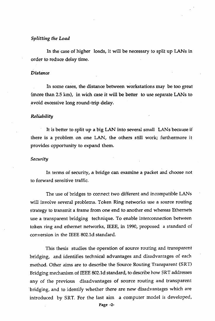
Splitting the Load
In the case of higher loads, it will be necessary to split up LANs in
order to reduce delay time.
Distance
In some cases, the distance between workstations may be too great
(more than 2.5 kin), in with case it will be better to use separate LANs to
avoid excessive long round-trip delay.
Reliability
It is better to split up a big LAN into several small LANs because if
there is a problem on one LAN, the others still work; furthermore it
provides opportunity to expand them.
Security
In terms of security, a bridge can examine a packet and choose not
to forward sensitive traffic.
The use of bridges to connect two different and incompatible LANs
will involve several problems. Token Ring networks use a source routing
strategy to transmit a frame from one end to another end whereas Ethernets
use a transparent bridging technique. To enable interconnection between
token ring and ethernet networks, IEEE, in 1990, proposed a standard of
conversion in the IEEE 802.1d standard.
This thesis studies the operation of source routing and transparent
bridging, and identifies technical advantages and disadvantages of each
method. Other aims are to describe the Source Routing Transparent (SRT)
Bridging mechanism of IEEE 802.1d standard, to describe how SRT addresses
any of the previous disadvantages of source routing and transparent
- bridging, and to identify whether there are new disadvantages which are
introduced by SRT. For the last aim a computer model is developed, Page -2-

using a SIMSCRIPT simulation package, in order to determine the relative
performance of Source Routing and Transparent bridging under certain
conditions.
Page -.3-

Chapter 2 LAN BRIDGES
2.1 IEEE 802 STANDARDS AND OSI MODEL
This section will explain the relationship between IEEE 802 protocol
structure for LANs and the ISO Open System Interconnection Model. Figure 2.1 shows the relationship between the IEEE 802 standards and the
OSI model [13].
OSI IEEE
IEEE 802.1 Higher level Interface
IEEE 802.2 Logical Link Control (LLC)
Higher Layer
Data Link Layer
Physical layer
IEEE 802.3 CSMA/CD
Medium Access
CSMA/CD media
IEEE 802.4 Token Bus
Medium Access
Ttoken Bus media
IEEE 802.5 Token ring
Medium Access
Token ring media
IBM cabling system
FIGURE 2.1 : IEEE 802 STANDARDS AND OSI MODEL
The differences lie in the Physical layer and Data Link layer. In the
IEEE 802 model, the Data Link layer is supposed to be on two levels i.e.
Logical Link Control (IEEE 802.2) and Media Access Control. In Media
Access Control, IEEE specifies the access strategy where 802.3 uses CSMA/CD
(Carrier Sense Multiple Access and Collision Detect), 802.4 uses Token Bus
Page -4-

and 802.5 uses Token Ring. The IEEE 802.1 standard is responsible for the
interface between the 802 Model and OSI Model. This task is done by IEEE
802.1a which describes the relationship between the IEEE 802 standard and
the ISO-OSI Model; IEEE 802.1b specifies the Media Access Control; and
IEEE 802.1d specifies the architecture and protocol for the interconnection
of 802 LANs.
The IEEE 802.1d standard explains the interconnection between 802.3
and 802.5 LANs. Source Routing and Transparent Bridge, which is
commonly called SR/TB, is used to interconnect IEEE 802.3 and IEEE 802.5
LANs. Such Interconnection requires a conversion software in the bridge
because they have many differences in MAC level. Recently, IEEE developes
new bridging method, which is called SRT (Source Routing Transparent)
bridging method, to provide more interoperability between Source Routing
and Transparent Bridging methods. The implementation of SRT bridge
requires some modifications of Source Routing so that a conversion software
is no longer needed.
2.2 TOKEN RING NETWORKS
2.2.1 Introduction
The Token Ring uses star-wired ring topology and follows the IEEE
802.5 standard protocol for signalling and token passing. The transmission
media which are used can be shielded or unshielded twisted pair cables.
The speed can be 4 Mbps or 16 Mbps. The maximum number of devices
that can be attached is 260 and each device or workstation uses an adapter
to handle token recognition and data transmission. The adapter is also
responsible for frame recognition, token generation, address recognition,
error checking and logging, timeout control and link-fault detection.
A few Multistation Access Units (MAU) are used as a wiring
concentrator. Each MAU provides ring access to a maximum of eight
workstations and works at Physical layer level. To enlarge the network, a
Page -5-

1 1 1 6 bytes Variable Length
Variable 4 bytes Length byte byte
6 bytes byte byte byte
bridge can be used to connect one ring to another ring. The bridge appears
to be a normal node in a ring and it is normally a PC which has two
adapters attached to each ring.
2. 2. 2 MAC Frame Format
The basic transmission unit is a frame which consists of a number
of fields of one or more bytes. When there is no information to be sent
then the frame changes to be a token[13].
A Token has only three fields i.e. a Starting Delimeter (SD), an
Access Control (AC) and an Ending Delimeter (ED) as shown in Figure 2.2.
A valid token or frame will start with the Starting Delimeter byte. The
next field is the Access Control field which consists of Priority Bits, a
Token Bit, and a Monitor Bit (see Figure 2.3 for details). A workstation can
have a frame with low priority (000) or high priority (111). A Token bit
has a value of one for frame and zero for token. A Monitor bit is used to
prevent continuous circulation of frames or non-zero priority tokens.
Physical Trailer 110 I
I SD \C
I FC Destination
Address Source Address
Routing Information (Optional)
Information Field (optional)
Frame Check Sequence
ED
I m
I
1 • Physical Header
SD AC ED
FIGURE 2. 2 : FRAME AND TOKEN FORMAT
A Frame Control Field consists of Frame Type Bits and Control
Bits. Frame Type Bits will be 00 for the MAC frame and 01 for the LLC
frame and the others are currently undefined frames. Control Bits indicate
how the frame is to be buffered.
Page -6-

Byte 0 l!trial■■■
D CEE1111111111
J_110 JK 0 0 01 SD
J = Code Violation K = Code Violation
PPIPIT 1 IRIRI AC
P = Priority Bit T = Token Bit M = Monitor Bit S = Reservation Bit
MG11131221 FC
F = Frame Type Bit r = Reserved Bit Z = Control Bit
FIGURE 2.3: FORMAT AND CONTENT OF SD, AC AND FC
The routing information is an optional field ; this field is omitted
if the frame is not leaving the source ring. The Routing Information Field
consists of a Routing Control Field and several segment numbers (Figure
2.4).
2 bytes 2 bytes 2 bytes 2 bytes
Routing Segment Segment Segment Control Number Number Number
B = Broadcast Indicators L = Length Bits D = Direction Bit F = Largest Frame Bits r = Reserved Bits
FIGURE 2.4 : ROUTING INFORMATION FIELD
There are four functions of the routing control field i.e. as Broadcast
Indicator, Length Bit, Direction Bit and Largest Frame Bit Statement.
BROADCAST INDICATOR BITS : The purpose of the Broadcast Indicator
is to indicate whether the frame is ; Non-broadcast or B'Oxx' (the frame is
sent along a specific path); All-route broadcast or B'10x' (the frame is sent
to all segments in the network or all interconnected rings), and the Single-
route broadcast or B 1 1 1 x' (the frame is sent to all segments but only one
Page -7-

copy of the frame appears on each segment). Further explanation is in the
next section.
LENGTH BITS : Length bits are used to indicate the length of the routing
information field.
DIRECTION BIT: The Direction bit enables the bridge to interpret the
• route; if this bit is set to zero the bridge interprets and reads the routing
information field from left to right or vice versa.
LARGEST FRAME BITS:. The Largest frame bits indicate the length of the
information field to be read. The Typical value of Largest Frame Bits are
'000' (516 bytes in the information field), '001' (1500 bytes), '010' (2052
bytes) and the biggest value is '110' (17800 bytes in the information field).
Each ring has a specific number called a segment or ring number
and each bridge is assigned a bridge number. Ring and Bridge Numbers
will form a route designator with 12 bits for a ring number and 4 bits for a
bridge number.
2. 2. 3 Source Routing
To establish an interconnection between two networks a bridge is
required which works at the data link layer. In source routing, a frame
flows through bridges from an originating station to a destination station
by following a defined route in the routing information field of the frame.
Routing information is obtained by a route determination process as
described below.
An alternative solution is to maintain the routing information in
tables at the level of participating bridge. The destination address can be
on the same ring or different ring. If the destination address is unknown
then the workstation will perform a determination process i.e. On-ring
determination for the same ring and Off-ring determination for different
rings.
Page -8-

ON-RING DETERMINATION PROCESS: In on-ring determination, the
source station sends a X[D (Exchange Identification) command LPDU(Link
Protocol Data Unit) on the local ring with the address of the destination
and without any routing information. The destination station responds
with a KID response LPDU. If there is no response LPDU returned within
a specific amount of time then the destination is not on the local ring and
the off-ring determination is initiated.
OFF-RING DETERMINATION PROCESS : In off-ring determination, there
are two main dynamic route discovery processes, namely an all-route
broadcast route determination and a single-route broadcast route
determination.
All-route broadcast route determination
The source station sends a test or XED command LPDU to all rings
where the first two bits of the RI (Routing Information) field are set to
binary '10x'. This triggers all bridges to copy the LPDU frame and forward
it until the destination address is reached. The frame will accumulate
routing information as it passes through bridges along the way. It is
possible that there is more than one route available to the destination
address so that more than one LPDU reaches the destination station. Any
received command LPDU will be returned as a response LPDU to the
originating station by setting the first RI (Routing Information) bit to
binary '0' and the direction bit to binary '1'. This forces the frame to flow
back to the source station via the route as developed in the LPDU frame
when it is received. The source station selects the preferred route from all
returned response LPDUs.
Single-route broadcast route determination
The source station sends a KED command LPDU to all rings where
the first two bits of the RI field are set to B' 11x' so that exactly one copy
appears on each ring. The frame will accumulate routing information as it
Page -9-

passes through bridges along the way. The XID command LPDU is then
returned as a response LPDU with the first two RI-bits set to B'10 ' indicating
all-routes broadcast. Again, multiple response LPDUs may be received by
the source station. The source station chooses the routing information
from the received responses.
When a bridge receives a frame to forward to a ring, the bridge
compares the route designators in the routing information field with its
attached ring numbers and bridge number. Four conditions might occur
in the bridge :
1. If there is a target ring number in bridge address table for all-route
or single-route broadcast frame; then the bridge discards the
frame because it has already circled the target ring.
2.If there is no target ring number in bridge address table for all-route
or single-route broadcast frame; then the bridge adds its route
designator to the frame's routing information field and forwards
it.
3. If there is a ring number, bridge number and ring number
combination in bridge address table for non-broadcast frame;
then the bridge forwards the frame to the indicated ring.
4. If there is no ring number, bridge number and ring number
combination, match in a non-broadcast frame; then the bridge
discards the frame.
When the frame reaches its destination, the sequence of route
designators describes the path from the source ring to the destination ring.
Page -10-

2 Variable 0 - m Length padding
7 bytes
I = Individual address (B'O' G = Group address (B . 1') U = Universally admin. (B'0')
= Locally admin. (B'1) 48 bits
2. 3 802.3 LANs
2. 3. 1 Introduction
An IEEE 802.3 LAN (example Ethernet) uses a bus topology and follows the CSMA/CD access protocol ( Carrier Sense Multiple Access and
Collision Detection). It uses baseband transmission method at 10 Mbps on a common shielded 50 ohm coaxial cable. A repeater is used in every 500
metre segment to intensify the signal; the maximum number of segments (groups of workstations) that can be attached to a particular segment is five. For the total LAN, 1024 attachments (segment, workstation and pheripherals) can be allowed in a distance not exceeding 2.5 kilometres.
2. 3. 2 IEEE 802.3 MAC Frame
Figure 2.5 shows the MAC frame format of the IEEE 802.3 LAN[13].
Physical Header -01
FCS Protection
Physical Tril ero...
0.1
Preamble SD Destination Source LF Information PAD FS Address (DA) Address (SA)
FIGURE 2.5 : IEEE 802.3 MAC FRAME FORMAT
The Preamble allows the physical layer signalling circuitry to
synchronize with the received frame timing circuitry. SA or DA can be
either 2 or 6 bytes, but all stations must use the same addressing structure,
otherwise it will cause an issue when two LANs are connected by a bridge.
Page -11-

The Length field (LF) indicates the actual length of the information field.
The maximum frame length is 1518 bytes. The Padding field contains
padding characters in case the minimum frame length requirement is not
met (512 bits). The FCS uses a cyclic redundancy check algorithm.
An invalid frame is not passed to the next higher protocol layer,
but it is discarded at the MAC level. This can occur when the frame does
not contain an integral number of bytes, or frame length field is inconsistent
with the actual frame length, or the FCS value calculated by the destination
station does not match the FCS value contained within the frame.
2. 3. 3 Transparent Bridging
This section will study the use of bridges in an 802.3 LAN. Before
studying the use of bridges, it is first desirable to understand the functional
differences between repeaters, bridges and gateways.
REPEATERS : Repeaters work on the physical layer and their tasks are
only to copy individual bits between cable segments.
BRIDGES: Bridges work on the data link layer and their tasks are to store
and forward the frames between the LANs.
GATEWAYS: Gateways work on the network layer and their tasks are to
store and forward packets between dissimilar networks.
Figure 2.6 shows how they are connected and Figure 2.7 shows how the
bridge works[1].
Page -12-

B = Bridge G = Gateway
ci 4 4 4 802.3 LAN 802.3 LAN 802.3 LAN
FIGURE 2.6 : A TYPICAL NETWORK [1]
The 802.3 LAN uses a transparent bridge for connecting buses. This
bridge is designed with complete transparency, so that when the bridge is
plugged in, it will work instantly without requiring hardware changes,
software changes, setting of address switches, downloading of routing
tables or parameters. Furthermore, the existing LANs are not affected by
plugging in a new bridge.
Host A Host B
FIGURE 2.7 : THE OPERATION OF BRIDGE
Page -13-

The Transparent bridge accepts the frames and then decide whether
to discard or forward an incoming frame and on which LAN to put it.
These decisions are based on the address table inside the bridge. This table
will list every possible destination, which LAN it belongs to, and which
LAN can be passed through to get to it. Routing procedures are as follows
[1];
* If the destination and source LAN are same then discard the
frame.
* If the destination and source LAN are different then forward the
frame.
* If the destination LAN is unknown then use "flooding"[1],
explanation below.
When the bridge is initially plugged in, its address table is empty so
that it does not know any addresses in any of the LANs. This also occurs
when a new workstation is initially plugged in, and its address is not
known by any bridge in the cascade. If this happens the bridge will use the
Flooding Algorithm. This algorithm is stated as follows: every incoming
frame is sent out on every outgoing line except the one it arrives on, so
that it generates a vast number of duplicate frames[1]. When the frame
arrives, the bridge will know its address, its LAN, or the LAN which can
be passed to reach the incoming frame address, for example (see Figure
2.8) if bridge 1 sees a frame of station C in LAN 2 then bridge 1 will know
that station C can be reached by passing LAN 2. This is a typical example of
Baran' s backward learning method[1]. This approach make it possible to
move the workstation or the bridge to the other end of bridged LANs and
it aalso allows dynamic topology because whenever a frame comes into
the bridge, the bridge will update its address table t current connections.
Figure 2.9 shows a bridge forwarding and bridge learning flow chart[4,14].
Page -14-

FIGURE 2.8 : A TYP ICAL LAN CONFIGURATION
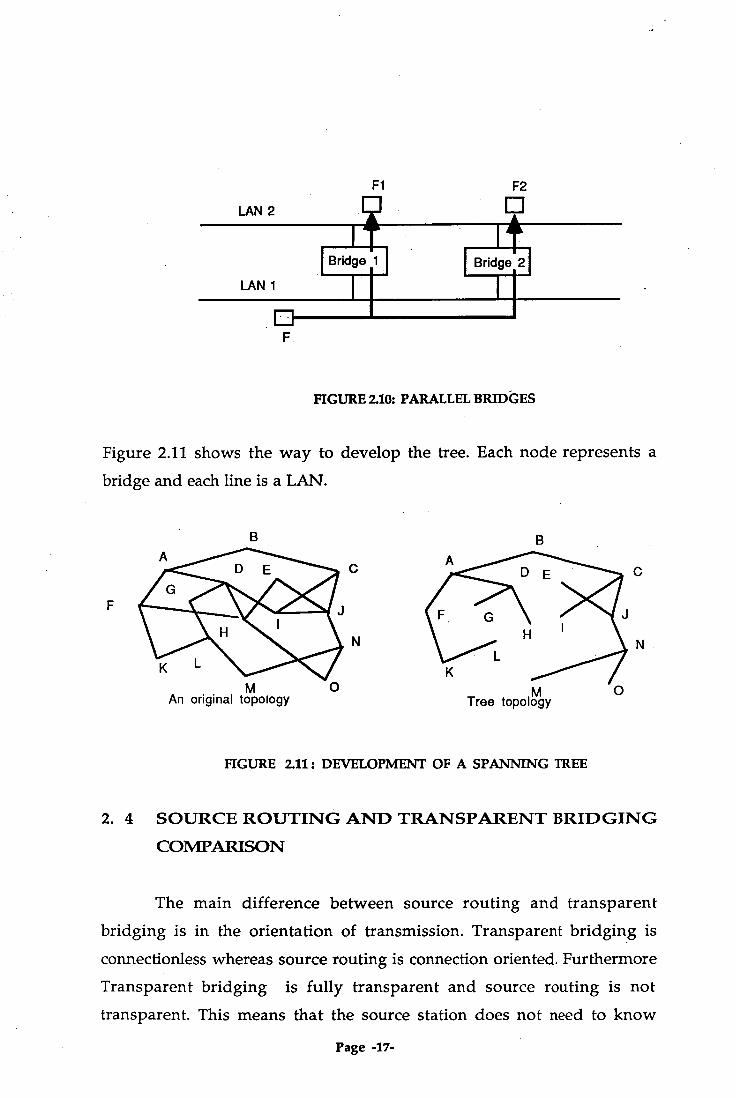
To increase reliability, parallel bridges can be used for connection
of two LANs as shown at Figure 2.10[1]. However, this can cause another
problem where it creates loops in the topology if a frame with an unknown
destination comes to the bridge. Bridge 1 sees the unknown frame F in
LAN 1 and copies it to Fl in LAN 2. On the other hand, Bridge 2 copies F
to F2 in LAN 2. Furthermore, Bridge 1 sees F2 in LAN 2 and copies it to F3
in LAN 1 and on the other hand Bridge 2 sees Fl and copies it to F4 in
LAN 1 and so on, causing a looping. To solve this problem, the Transparent
bridge uses a "Spanning Tree"[4] to guarantee that there is only one path
between the source address and the destination address, threby making
looping impossible.
To develop a Spanning Tree, every few seconds each bridge
broadcasts its identity (a serial number installed by the manufacturer and
guaranteed to be unique). By using a distributed algorithm, one bridge is
then selected as the root of the tree, usually the bridge with lowest serial
number. The tree is constructed by selecting the shortest path to the root.
This algorithm is continually updated to keep the tree current.
Page -15-

No
•
Bridge learning
No.
Finished
Update direction and timer
Add source to database with direction and timer
Check address table
Bridge Forwarding
Discard Frame
Yes
Frame received without error
Forward frame to indicated LAN
Look up address table
Check Forwarding port
Flooding
FIGURE 2.9 : BRIDGE FORWARDING & LEARNING FLOW CHART
Page -16-
Fl F2
LAN 2
Bridge 1 I Bridge 21
LAN 1
FIGURE 2.10: PARALLEL BRIDGES
Figure 2.11 shows the way to develop the tree. Each node represents a
bridge and each line is a LAN.
An original topology Tree topology
FIGURE 2.11: DEVELOPMENT OF A SPANNING TREE
2. 4 SOURCE ROUTING AND TRANSPARENT BRIDGING COMPARISON
The main difference between source routing and transparent
bridging is in the orientation of transmission. Transparent bridging is
connectionless whereas source routing is connection oriented. Furthermore
Transparent bridging is fully transparent and source routing is not
transparent. This means that the source station does not need to know
Page -17-

which bridges will be based because the bridges learn the location of the
destination address by using "backward learning". In source routing, if
the destination address is unknown then a discovery frame has to be sent
out to discover the routing information.
The workstation at transparent bridging does not need to worry
about the bridging scheme because it is arranged by the bridge. In source
routing the workstation must actively participate, so that the complexity
is in the workstation rather than in the bridge. Furthermore, a failure or
change of bridge position or network topology, will be handled by the
workstation. In contrast, in transparent bridging those changes will be
handled by the bridge.
The Transparent bridge will automatically configure the network
topology and does not need network management. In source routing, the
address and bridge number must be manually installed and must be unique.
It may be difficult to relocate the bridge or workstation because it needs to
be arranged again. If there is a mistake in this arrangement, it may be
difficult to detect. On the other hand, there is no collision in source routing
so the channel utilization can be increased. In this case, source routing has
deterministic performance[15].
2.5 BRIDGE PROBLEM OF 802.3 AND 802.5 LANS
General problems of Token ring and Ethernet are different frame
formats, different data rates, different maximum frame lengths[1]. The
transmission of a frame from token ring to ethernet or vice versa requires
reformatting of the frame in the bridge. This process is likely to end up
with errors which are difficult to detect.
When transmitting a continuous stream of frames from ethernet
(10 Mbps) to token ring (4 Mbps), the bridge has to buffer those frames in
Page -18-

enough memory , otherwise overloading occurs and some information
will be missed. Another problem which is related to the different speeds
of Ethernet and Token ring, suppose ethernet transmits a long frame to
token ring, and after sending the last bit it sets a timer and waits for
acknowledgment. There is a big problem when the timer goes off before
the bridge forwards whole bits to the slower LAN. This will cause the
source LAN to retransmit the same frames again, and after several attempts
it will stop and tell the higher layer that the destination station is off.
Token Ring and Ethernet have different frame lengths where the
• maximum frame length for the 10 Mbps Ethernet is 1518 bytes and for
Token Ring, 17800 bytes. This is the most serious problem. Suppose the
Token Ring wants to transmit a frame of 17800 bytes to Ethernet. The
Ethernet that has a maximum frame length of 1518 bytes can not accept
that long frame. Splitting the long frame into a number of small frames is
not the task of the bridge. In this case there is no way, and the frame must
be discarded.
This section examines the specific problems between 802.3 to 802.3,
802.5 to 802.5 and 802.3 to 802.5 or vice versa, more explanation see [1].
From 802.3 to 802.3, basically there is no major problem. The only problem
is if the bitrate of the bridge is slower than the bitrate of the LAN. Then
the memory of the bridge may be out of buffer and drop some frames
when transmitting a long continuous run of frames.
From 802.3 to 802.5, the problems are different frame formats and
different speeds. Another problem is that 802.5 has priority bits whereas
802.3 has not. So when reformatting the frame, priority bits must be inserted.
The best way is to insert the high priority so that the frame can reach the
destination address faster because it has probably suffered a long delay due
to collision.
Page -19-

From 802.5 to 802.5, there is no major problem in this connection.
The only problem is that the frame has A and C bits in the Frame Status
field. This field is 'ACrrACrr' where A is to indicate that the destination
station has recognized the frame, B is to indicate that the destination
station has copied the frame and r is a reserve bit. These bits are set by the
destination to tell the sender. The bridge may tell the sender that the
frame has been copied, whereas in fact the destination station is off.
From 802.5 to 802.3, the problems are due to different frame formats,
and different maximum frame lengths. Problems with A and C bits can
also occur here as mentioned before. A problem with priority bits is where
those bits may be discarded by the bridge so that high priority frame becomes
a common frame. For instance, if a token ring transmits a frame to another
token ring via ethernet then priority bits will be lost in the intermediate
LAN.
Page -20-
Chapter 3 SOURCE ROUTING TRANSPARENT (SRT) BRIDGE
3.1 Introduction
Source Routing and Transparent Bridging are different methods
for interconnecting two LANs. Transparent bridging is easier to connect
and manage so that it is a widely accepted standard in the market. Source Routing performs better but it is not fully compatible with the Transparent
Bridge. This incompatibility causes problems if the 2 systems are connected to each other. These problems are, difficult interconnection, interoperability
problems and degraded network operation. From the customer's point of view, they want an "agreement" between the Source Routing Bridge and
the Transparent Bridge so that they can be more compatible and can fulfil
the following conditions.
- Transparent Bridge can be used for non-Source Routing stations.
- Source Routing Bridge can be used for Source Routing stations.
- Freedom to mix Source Routing and Transparent Bridges on
the same LAN.
- Freedom to mix Source Routing and Transparent stations on the
same LAN.
- Guaranteed Connectivity between any pair of stations.
In solving these compatibility problems, the IEEE working group proposed a draft for the SRT bridge[12]. In this draft there are changes for
SR bridge (802.1 bridging operation) and the SR station (802.5 and 802.1 end system operation), on the other hand there is no change for the TB
bridge and the TB station. This draft mentions that the MAC of the SRT
bridge should conform to the following conditions.
1. Conform to the MAC standard of the IEEE 802.3, the IEEE 802.4 and the IEEE 802.5 and conform to the LLC of the IEEE 802.2.
2. Relay and filter frames on the basis of information contained in
the Filtering Database. Page -21-

Higher Layer Entities
LLC Entity LLC Entity
MAC Relay Entity
1 SR Logic
I TB Logic
Mac Entity MAC Entity
3. Provide the capability to control the mapping of the priority of
forwarded frames.
4. Maintain the address information table required to make frame
filtering decisions and state the value of database size and the maximum number of entries that can be held in the filtering
database. 5. Use either a 48-bit Universally Administered Address, or a 48-bit
Locally Administered Address, or a 16-bit Locally Administered
Address. 6. Implement the Spanning Tree Algorithm to reduce the Bridged
Local Area Network Topology to a single spanning tree.
7. Provide the capability to assign the value of a Bridge Priority, Port Priority and Path Cost for each port to allow configuration
of the Spanning Tree Topology.
8. Support the Management of Bridges, explanation in Section 3.5.
The SRT bridge is actually a twin function bridge[12]. It acts as a TB
bridge if it receives TB frames and acts as a SR bridge if it receives SR frames. The bridge works at MAC level and it can distinguish whether the
frame is an SR frame or a TB frame by using a Routing Information Indicator (RI). In this case, if the value of RII is equal to 1 then the bridge
will consider the frame as an SR frame; otherwise as a TB frame. The following diagram (Figure 3.1) shows the situation of how the SRT bridge
works.
FIGURE 3.1 : BRIDGE DIAGRAM
Page -22-

• To further understand the SRT bridge, the next sections will explain
MAC service support, principles of operation, the spanning tree algorithm
and bridge management.
3.2 MAC SERVICE
The function of the MAC bridge in Bridged Local Area Network is
to connect several LANs by providing MAC services to the MAC service
user in the end stations, and relaying frames between the separate MACs
of the Bridged LANs. The services provided are request primitives and
corresponding indication primitives conveying user data with
unconfirmed service. The use of confirmed service by end stations
communicating across the bridge is not supported.
The quality of MAC services provided by a bridge should not be
inferior to that provided by a single LAN. The parameters to be considered
are those relating to the following[12].
1. Service Availability
2. Frame loss
3.Frame misordering
4. Frame duplication
5.The transit delay experienced by frames
6. Frame lifetime
7.The undetected frame error rate
8.Maximum size of service data unit supported
9.User priority and throughput
Service Availability
Service availability is measured as the total time during which the
service is provided to the end station. The service availability can be
increased by automatic reconfiguration of bridged LANs in order to avoid
Page -23-
the use of failed components ( e.g. repeater, cable, or bridge itself) in the
data path. A bridge may deny service and discard a frame of a station in
order to preserve other aspect of the MAC service when automatic
reconfiguration takes place; hence service availability is lowered for that
end station. To maximize the service availability, no loss of frame or delay
of service should be caused by the bridge except as a consequence of a
failure, removal or insertion of a bridge or as a consequence of the
movement of an end station.
Frame Loss
A frame transmitted by a source station can fail to reach the
destination station due to the corruption in transmission at the physical
layer level. The use of the bridge can cause frame loss and it should
introduce minimum additional frame loss. The bridge may discard a frame
for the following reasons.
1.The maximum frame lifetime is exceeded.
2. The internal buffering capacity is full due to continuous arriving
of frames at a rate in excees of that at which they can be
transmitted.
3. The size of frame exceds the maximum frame length supported
by the medium access control procedures employed on the LAN
to which the frame is to be relayed.
4. The frame arrives at a time when the topology of the bridge
LAN is being changed to maintain other aspects of quality of
services.
Frame Misordering
The operation of bridge does not misorder the frames with the
same user priority. The bridge is capable of connecting the individual
MACs in such a way that multiple paths between a source station and
destination station may exist. To ensure that there is one active path to be
followed between any pair of stations, the operation of protocol is required
Page -24-

in order to preserve the order of arriving frames.
Frame Duplication
The bridge MAC sublayer does not permit frame duplication. The
duplication is possible if there is more than one path between the source
and destination stations. Once more, the protocol needs to guarantee one
active path available in any pair of stations.
Transit Delay
Transit delay is the time taken to receive a frame plus that taken to
access the media onto which the frame is to be relayed. Since the MAC
service is provided at an abstract interface it is not possible to specify the
total frame transit delay precisely.. However, it is possible to measure
those components of delay associated with media access; hence the
transit delay introduced by the bridge can be measured. This transit delay
has to be short to ensure that the maximum life time of the frame is not
exceeded.
Frame Lifetime
The Frame has a maximum lifetime and it will be discarded by the
bridge if that value is exceeded. The maximum frame lifetime is necessary
to ensure the correct operation of higher layer protocols.
Undetected Frame Error Rate
Each frame has a Frame Check Sequence (FCS) field which is
appended by the MAC sublayer of the source station prior to transmission
and checked by the destination station on reception. Undetected errors are
protected against by the use of FCS. Recalculation of the FCS is necessary
within a bridge providing a relay function between IEEE 802 MACs of
dissimilar types. This introduces the possibility of additional undetected
errors arising from the operation of the bridge.
Page -25-

Maximum Service Data Unit Size
The Maximum service data unit size varies with the MAC method
and its associated parameters e.g. speed. Within bridged LANs, this value is the smaller of that supported by the LANs. The bridge should not relay a frame to a LAN which does not support the size of service data unit
conveyed by that frame.
Priority
The bridge MAC sublayer can provide the priority of service to the
end station. A request primitive with a high priority may be given
precedence over other request primitives made at the same station or at
other stations attached to the same LAN.
Throughput
The total throughput of the bridged LANs can be greater compared
to an equivalent single LAN because the bridge can localise traffic within a smaller size of LAN by filtering frames. In some cases, the throughput may be lowered by frame discard due to inability to transmit at the
required rate of the LAN.
3.3 PRINCIPLES OF OPERATION
Three main principal elements of bridge operation are; (1) Relaying
and Filtering of frames, (2) Maintenance of the information required to make frame filtering and relaying decisions, (3) Management of the bridge[12]. The bridge functions that supports the relaying of frames include;
a. Frame reception
b. Frame discard if it receives in error due to corruption
c. Frame discard if the frame_type is not user_data_frame
d. Frame discard due to the application of filtering information
e. Frame discard if service data unit size is exceeded
Page -26-
f. Frame discard if maximum bridge transit delay is exceeded
g. Mapping of service data units and recalculation FCS
h. Selection of outbound access priority
i. Forwarding of received frames to other bridge ports
j. Frame transmission
The functions that support the use of filtering information in the
bridge include;
a. Permanent configuration of reserved address
b. Explicit configuration of static filtering information
c. Automatic learning of dynamic filtering information
d. Updating the address filtering database
e. Calculation and configuration of bridged LAN topology
Frames are accepted at one port and delivered to other ports for
transmission. The processes included in this MAC relay entity are the
Forwarding process, Learning process and Filtering process. The
Forwarding process is applied when passing the frame filtering address on
the basis of information contained in the filtering database. The Learning
process is a process to update the address in the filtering database by source
address of the receiving frame. The Filtering process looks at the address
information database and decides whether forward or discard the frame.
Each bridge port supports the operation of LLC procedures in order
to support the other types of LLC procedure which may be used by other
protocols. Figure 3.2 shows the reception and transmission of the Bridge
Protocol Data Unit by the Bridge Protocol Entity. Port state information is
active when the bridge management permits the port to participate in
relaying frames if it is capable of doing so.
A frame received on a bridge port and submitted to the Forwarding
Process shall be queued for transmission on each of the other bridge ports
Page -27-

Bridge Protocol Entity
LLC Entity
Port State Information
Port State Information
LLC Entity
Frame Transmission
!
Filtering Database
Frame Transmission
Frame Reception
Frame Reception
if and only if;
1. The port on which the frame was received was in a forwarding
state, and
2.The port on which the frame is to be transmitted is in a forwarding
state, and
3. Either; (a) The filtering database indicates that frames with the
value of destination address should be forwarded, or. (b) The
value of the source and destination address are the same, and
the bridge is
FIGURE 3.2 : SRT BRIDGE OPERATION
configured to not filter such frames in order to support the
optional LLC duplicate address check function and
4. The maximum data unit size supported by the LAN to which
the transmission port is attached would not be exceeded.
The forwarding process provides buffer storage for queued frames
and the order of queued frames should be maintained. A frame queued by
the forwarding process shall be removed from the queue if :
a. On submission to the MAC entity port; no further attempt should
Page -28-

be made to transmit the frame on that port even if the
transmission is known to have failed.
b. If the time of buffering storage is exceeded for that frame, and
not subsequently transmitted.
C. If the frame lifetime is exceeded.
The frame forwarding process considers the priority of forwarded
frames. The CSMA/CD access method treats all values of access priority
equally.
The learning process observes the source -address of frames
received on each port and updates the filtering database. If a frame with a
new source address is received then the bridge will file it in filtering
database, and if the filtering database is full when a new entry is made
then the existing address will be removed to make room for the new
entry.
The filtering database contains the address information which is
configured by management action (static value) or automatically entered
by the learning process (dynamic entry). Static entries can not be removed
without management permission.
3.4 THE SPANNING TREE ALGORITHM AND PROTOCOL
The spanning tree algorithm and its associated bridge protocol
operate to support the quality of the MAC service. This algorithm and
protocol will meet the following goals.
1. To configure the active topology of bridged LANs into a single
spanning tree so that there is one route between any pair of end
stations.
2. To provide fault tolerance by automatic reconfiguration of
topology as a result of bridge or cable failure.
Page -29-

3. To keep the structure of active topology in a period of time in
order to minimize unavailable time of service.
4. Allowing the management to reconfigure the topology to meet
the goals of performance management.
5. Operate transparently to the end stations.
6. The communication bandwidths consumed by the bridges in
establishing and maintaining the spanning tree should be a
small percentage of the total available bandwidths and the high
throughput.
In order to develop the Spanning Tree Topology, MAC Bridges
require :
1. A unique MAC group address, recognized by all the bridges,
which indentifies the Bridge Protocol Entities of all bridges
attached to an individual LAN.
2.A unique identifier for each bridge.
3.A port identifier for each bridge port.
4. A means of assigning the relative priority of each bridge within
Bridged LANs.
5. A means of assigning the relative priority of each port within an
individual bridge.
6.A means of assigning a path cost component to each port.
The bridge with the highest priority bridge identifier is selected as
the root; this is the identifier with the lowest numerical value. Once the
root is known, every bridge port will calculate the Root Path Cost.
The designated port for each LAN is the bridge port for which the value
of the Root Path Cost (time) is the lowest.
Page -30-

LAN 5
(1 port
port
I port
I ■
-7
port LAN 3 LAN 4 )
LAN 2
1 port port
\J port 11 pont.)
\..1 port
LAN 1
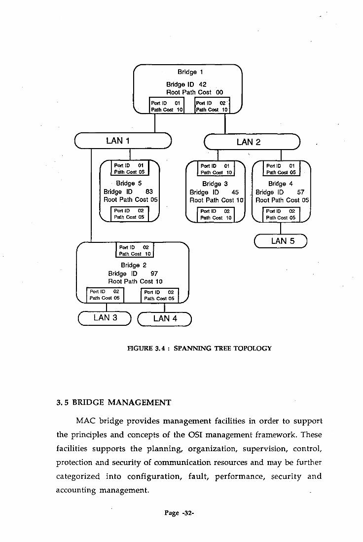
FIGURE 3.3: BRIDGED LANs
The components of the bridge identifier of each bridge, the path cost and
port identifier of each bridge port can be managed allowing a manager to
select the active topology. Figure 3.3 shows a bridged LAN and Figure 3.4
is its Spanning Tree Topology.
Bridges send a type of Bridge Protocol Data Unit (BPDU) to other
bridges which carries the configuration of the bridge and consists of the
unique identifier of the bridge, the cost of the path to the root from
transmitting port, the identifier of transmitting bridge and the identifier
of transmitting port.
Page -31-
Bridge 1
Bridge ID 42 Root Path Cost 00
Port ID 01 Path Cost 10
Port ID 02 Path Cost 10
C Port ID 01 I Path Cost 05
1 C I
Port ID 01 •N Path Cost 10
Bridge 5 Bridge ID 83 Root Path Cost 05
L 'ort ID 02 .... L., Path Cost 05
Bridge 3 Bridge ID 45 Root Path Cost 10
I Port ID 02 Path Cost 1011
I Port ID 02 Path Cost 10
Bridge 2 Bridge ID 97 Root Path Cost 10
Port ID 02 Path Cost 05 I Port ID 02
Path Cost 05
LAN 4
LAN 1
LAN 2
Cl Port ID 01 Path Cost 05
Bridge 4 Bridge ID 57 Root Path Cost 05
I Port ID 02 Path Cost 05
( LAN 5 )
FIGURE 3.4: SPANNING TREE TOPOLOGY
3.5 BRIDGE MANAGEMENT
MAC bridge provides management facilities in order to support
the principles and concepts of the OSI management framework. These
facilities supports the planning, organization, supervision, control, protection and security of communication resources and may be further
categorized into configuration, fault, performance, security and accounting management.
Page -32-

The configuration management is responsible for the identification
of communication resources, the supply of operational parameters, and
the establishment and discovery of the relationship between resources.
These facilities allow management to :
a.identify all bridges and their respective location and
b. identify the location of specific end stations for a particular
individual LAN in bridged LANs.
c.be able to remotely reset and reinitialize specified bridges.
d. be able to control the priority of bridge port in forwarding frames.
e. be able to set up a specific configuration of the spanning tree.
f. be able to control the transmission of frames with specific group
addresses to certain parts of bridged LAN.
The fault management is responsible for fault prevention, detection,
diagnosis and correction. This facility provides the ability to identify and
correct the bridge malfunction induding error logging and reporting.
The performance management is responsible for evaluation of the
performance of communication resources, and is also responsible for
evaluating the effectiveness of communication activities. These facilities
provide the means to acquire statistics regarding performance and traffic
analysis.
The security management is only responsible for protection of
resources. The accounting management provides the identification and
distribution of cost and the setting of charges. Unfortunately, there is no
specific facility for the security and accounting management.
The resources of MAC bridge to be managed are actually the entities
and processes incorporated within the bridge. The processes are including
Page -33-

frame receiving, frame filtering, frame discarding, frame forwarding and
other functions of frame relaying. The entities includes bridge
configuration, and port configuration. For further information is in [12].
3. 6 DISCUSSION
Source Routing Transparent Bridge (SRT) overcomes the
interoperability problems between Source Routing and Transparent
Bridging in bridged Local Area Network. This bridge acts as a Source
Routing Bridge when forwarding Source Routing Frames and acts as a
Transparent Bridge when forwarding Ethernet Frames. This mechanism
is based on Routing Information Field of frames containing a Routing
Information Indicator. When Routing Information Indicator is equal to
one then the frame is treated as Source Routing Frame and if a frame
contains Routing Information Indicator which is equal to zero then the
frame is treated as Ethernet Frame. The main advantage of such bridge
is that there is no translator required for connecting 802.3 and 802.5
LANs. In general, this concept is excellence but some difficulties remain
unclear because this proposal is still not complete yet.
As mentioned in Section 2.5, the general problems of this
interconnection are different frame format, different maximum frame
length and different data rate. The problem of different data rate is mainly
a technical problem, and the effect of this difference is a frame being
discarded at the bridge due to the limitation of buffer capacity. Such
problem can be simply avoided by using larger buffer capacity as required.
The different maximum frame length is actually a small problem and
easy to overcome, and the effect of this problem is a frame discarding
which occurs when Token Ring sends a maximum frame length of
about 17 kilobyte to Ethernet which only has maximum frame length of
about 1.5 kilobyte. Such problem can be overcome by changing the
algorithm of Source Routing in Source Routing Station where Source
Routing Station is asked not to send large frame or to split the large
Page -34-

frame before sending to Ethernet. As mentioned in SRT Draft that some
small changes for Source Routing Operation should be done so that a
small change of Source Routing Algorithm can be included whereas
Transparent bridge remains unchanged. The maximum frame length is
the maximum frame size that is supported by all LAN types in bridged
LANs. Otherwise, it may be constrained by the owner.
The problem of different frame format is not mentioned in the
SRT draft proposal. This problem can be simply handled by one of the
following categories of bridge operation [3]:
a.Passthrough Bridge : A bridge between two local area networks
whose Data Link functions and addressing system are identical can pass
frames through without changes.
b. Translation bridge : A bridge between two local area networks
whose Data Link functions and addressing system are sufficiently similar
(but not identical) may translate Data Link protocol to communicate
between dissimilar networks.
c.Encapsulation Bridge : A bridge between two local area networks
whose Data Link functions and addressing system are sufficiently
dissimilar (infeasible for translation) may encapsulate a frame. In this
case a frame that come from LAN A will be encapsulated by the bridge
using Data Link format of LAN B so that the frame can then easily
travel on LAN B.
Usually, the transmission of frames from Token Ring to Ethernet
or vice versa requires a translating software for converting or
reformating the frames in the bridge before passing them through. SRT
bridge does not need a translator because it is designed to act as a
Transparent bridge when passing the frames through Ethernet stations
and act as a Source Routing bridge when passing the frames through
Token ring stations. SRT bridge may just pass frames to the other end
stations because Token ring and Ethernet have the same addressing system
Page -35-
of 6 bytes, but it may be necessary for a station to have a particular
software in order to extract the information contents of frames. This
software should have the ability to decide which frame is Token ring
frame or Ethernet frame because the extraction of information is different
between Token ring frame and Ethernet frame. Using such a system, the
different frame formats are no longer a problem.
In Section 2.5, it is mentioned that 802.5 MAC frames have priority
bits whereas 802.3 MAC frames have none. A small problem arises
concerning the priority bits when Ethernet station sends frames to Token
ring stations. In such case, bridge may give high priority to Ethernet
frames before sending them to Token ring stations because they have
been probably suffered a long delay due to collision.
The problem about A and C bits in the frame status field of 802.5
MAC frames still remain unclear in the SRT draft proposal. These bits
are set by the destination station to tell the sender that the frame has
been already copied. To overcome this problem, the bridge must wait for
a replay from destination station before informing the source station
whether the frame has been copied or not. Unfortunately, such solution
will increase the transmission delay. The best way is to provide a command
for checking the destination station whether it is on or off, before sending
a stream of frames.
The advantages of SRT bridge are obvious. It overcomes the
compatibility problems between established LANs, i.e. Token ring and
Ethernet LANs, furthermore it will give more interoperability for FDDI
and even SRT bridge makes easier way for FDDI to specify Source routing
[12]. There is an "agreement" between Source routing and Transparent
bridging. Conceptually, Source routing becomes a subset of Transparent
bridging and Transparent bridging becomes a subset of Source routing.
The important thing of SRT bridge is its participation in developing a
Page -36-
spanning tree configuration thus guaranteing a path along the spanning
tree for frames sent without routing information, on the other hand SRT bridge supports Source Routing and provides at least one path for
connecting two LANs. From customer's point of view, SRT bridge
provides an opportunity to expand the existing LANs by connecting it to
other similar LANs.
If the SRT bridge is developed by following the underlying concepts
of MAC service as mentioned in Section 3.2, there would be no
disadvantages introduced. The things that have to be considered in
developing such a bridge are the speed and buffer capacity. If the speed is
too slow and buffer capacity is too small then many problems will arise.
From the customer's point of view, the only problem is cost of expantion.
Page -37-

Chapter 4 PERFORMANCE ANALYSIS
This chapter will consider performance analysis for both Source
Routing and Transparent Bridging Methods in bridged Local Area
Networks. In each method, it set up a model of the system and then both
simulation and queuing analysis will be employed. The simulation analysis
will use the SIMSCRIPT simulation program to calculate the delay and
throughput of the system. The queuing analysis will be derived based on
the access strategy which is used in each bridged LAN.
4.1 PERFORMANCE ANALYSIS FOR SOURCE ROUTING
4. 1. 1 Mathematical Analysis
The bridged LANs topology which will be analyzed is made up of
three serially connected LAN segments with one bridge connecting each
of the two links. This topology is simply drawn as follows :
FIGURE 4.1: THREE CONNEL EL) LAN SEGMENTs
To analyse this queuing problem, it is better to consider one ring
first and derive the formula. If we examine the system of one ring, it can
be shown in the following diagram[9,10].
Page -38-

FIGURE 4.2: TOKEN RING QUEUING SYSTEM
Since the token ring uses a token circulated around the ring of N
stations, it is apparent that the system has one server and there are N
queues of station around the ring. The arrival rate of frames at all stations
is assumed to follow Poisson Distribution and the service time follows
Exponential Distribution. The service time of this system consists of two
components which are the frame transmission time in each station and
the propagation delay around the ring/round trip delay.
If t = round trip / propagation delay
ti = frame transmission time at station i
N = the number of station in particular ring
then the service time (ts) will be
t5 =t + E ti (4.1)
Let the average length of frames is m and the speed of station i on
that particular LAN is q then,
ti = m/q (4.2)
If the speed of a station is the same as the other stations then
Equation (4.1) will be,
ts = t + N . t (4.3) (frame transmission time)
Page -39-

As shown in Figure 4.2 that Xi is the average arrival rate of frames
in station i. For the whole system the average arrival rate of frame is X,
where :
N. A. = (4.4)
i=1
To further deal with queuing analysis, the following symbols are
required to simplify the problem.
tw = waiting time in the queue
tq = total time spent in the system
(waiting time in the queue + service time)
q = the number of frames in the system
w = the number of frames in the waiting room/buffer
p = the utilization factor of the system
E(L) = average waiting time
E(t) = average service time
E(tq) = average total time spent in the system
t = tw + (4.5)
E(tq) = E(ç) + E(t) (4.6)
From Little's Formula :
p = X . E(ts) (4.7)
E(w) = A.. E(t) (4.8)
E(q) = A. . E(tq)
= X . E(tw) + p (4.9)
By assuming that the buffer capacity is unlimited then the average
number of frames in the system is E(q), where
E(q) — P (4.10) 1-p
Page -40-

hence,
E(tq) = E(q) — = p X X(1-p)
E(t) (4.11) (1-p)
A particular LAN which will be analyzed has a speed of 4 Mbps,
the number of stations attached to the ring is 25 and the ring size is about
600 m. The propagation delay of the twisted pair cable is taken as 5 ps per
km. If the average frame size is 1 kbyte (1024 bytes), according to Equation
4.3, the service time would be :
t N tsyncronization
= 3 ;Is + 25* (1024*8/4.106) s = 51.203 ms
The average time spent in the system is a function of system
utilization or throughput (utilization * max bitrate), see Equation 4.11.
Using this equation the time delay will increase as the increasing of
throughput as shown in Figure 4.3. It can be seen that the delay is small
as the throughput is increased to 75 % of utilization or at the throughput
of 3 Mbps. 1200
as -6 1000-
CD
800 -
600
400 -
200 -
0 2
3
4 Throughput (Mbps)
FIGURE 4. 3 : DELAY VS THROUGHPUT
Page -41-

• Delay
• The number of frame in Buffer
30
20
1 0
Throughput (Mbps)
4. 1. 2 Simulation of Token Ring
The characteristics of the delay using simulation agrees with the
mathematical analysis. Figure 4.4 shows the curve of delay vs throughput
and the number of frames waiting for the server vs throughput. This
simulation data can be seen in the appendices (Appendix 1).
FIGURE 4.4: DELAY & NUMBER OF FRAMES IN BUFFER VS
THROUGHPUT
The average number of frames waiting and the delay time increase
rapidly when the throughput is more than 75 %. In the simulation, the
utilization is increased by adjusting the average of the arrival rate of frame
in every station. It assumes that every station has the same priority to
access the token so that the queuing system is FIFO (First In First Out), and
every station has the same average frame of arrival rate.
4. 1. 3 Simulation of Source Routing
For three rings connected in cascade as shown in Figure 4.1, the
results of simulation are described in appendices (Appendix 3) and those
results are plotted as a graph as shown in Figure 4.5. The delay of the
frame within a LAN, in this case LAN 1, is almost constant at the
throughput below 3 Mbps whereas the delay of the frame from LAN 1 to
LAN 2 increases and the delay from LAN 1 to LAN 3 increases sharply Page -42-

5000
>. 4000 - cø
3000 -
2000 -
1000 -
due to the queue in the bridges.
n LAN 1 to LAN 3
• LAN 1 to LAN 2
ci Delay in LAN 1
3 Mbps
FIGURE 4.5: DELAY VS THROUGHPUT
This simulation assumes that the frames generated in every station
in LAN 1 have a probability of 60 % to travel within the local ring (LAN
1), 20 % to travel to LAN 2 and another 20 % to travel to LAN 3. The
frames generated in LAN 2 have a probability of 60 % to travel within ring
2 (LAN 2), 20 % to travel to LAN 1 and another 20 % to travel to LAN 3.
The frames generated in LAN 3 have a probability of 60 % to have a
destination station within LAN 3, 20 % within LAN 2 and another 20 %
within LAN1. The generation of random numbers is needed to decide
whether a frame is travelling within a local ring or a different ring. These
values are selected for convenience and are representative of real traffic
destination. Figure 4.6 describes these percentages.
FIGURE 4.6 : PERCENTAGES OF TRAFFIC DESTINATION
Page -43-

The speed of the bridge chosen is very slow at 56 Kbps[16] whereas
the LAN speed is 4 Mbps so that the delay in the bridge is big for the frame
length of 1 Kbyte as follows.
Delay = 1024 * 8 /56000 = 146.286 ms
Because of this high delay in the bridge, the frame which travels to
different rings suffers long delay due to the queue at utilization above
60%. Ring 2 suffers the highest delay compared to ring 1 and ring 3 because
ring 2 is responsible for the passage of frames from LAN 1 to LAN 3 and
from LAN 3 to LAN 1. Ring 1 and ring 3 suffer delays which are almost
the same. These data can be seen in the appendices (Appendix 3).
4.2 PERFORMANCE ANALYSIS OF 802.3 LANs
4. 2. 1 Mathematical Analysis
The 802.3 standard uses CSMA/CD access protocol. The basic concept
of CSMA /CD is simple. All stations listen for transmission on the line; if
the channel is idle do transmission. This is called the Carrier Sensing (CS)
procedure. It is very likely that more than one station is listening, discovers
that the channel is idle, and transmits simultaneously causing collision.
This is typical of the Multiple Access (MA) mode. After transmission, its
station sets up the timer and waits for acknowledgment; if the sending
and receiving packets are different then the collision has occurred. This is
a Collision Detection (CD) strategy. If this occurs then the station will send
a special signal notifying all other stations to abort their transmission. The
station then reschedules transmission to another time following "Binary
back off strategy". This strategy reschedules transmission based on a random
period of time which is a uniformly distributed random number. A
CSMA/CD model in Figure 3.7 shows the end to end delay (t).
Page -44-

A Two-way B Terminator
I 4 ■ I FIGURE 4.7 : CSMA/CD REPRESENTATION
Suppose m is a message length in seconds which is message length/channel speed. Figure 4.8 shows how to reschedule transmission.
Collision interval I 4
--011■ I 14.._ Time to detect a collision
I ,c
I 2 12T I t I
—god 1.4._ Sensing time
4
ed
t v = Virtual transmission time
FIGURE 4.8 : RESCHEDULING TRANSMISSION
In collision interval, there is a number of retransmissions. Suppose j is the average number of retransmissions before success. The worst-case
detection of collision is twice the end-to-end delay, as shown in Figure 4.9.
A
time
12 FIGURE 4. 9 : DETECTION TIME
The average transmission delay can be calculated as follows[2] :
=m +t + 2 (4.12)
Time
Page -45-

if a = t /m then t = m[ 1 + a(1+2j) ] (4.13)
Channel utilization will be
1 (4.14) P = mit" — 1 + a(1 + 2j)
end-to-end delay where a = packet length / channel speed
It is shown in the above formula that 'a' is an important factor to
adjust channel utilization. The utilization can be increased by keeping the
value of 'a' small. This can be done either by shortening the cable length or by reducing the transmission capacity in bps ( bits per second) to increase
the value of m.
To further analyse the system, it is necessary to find out the value of j. It is assumed that the length of the collision interval is geometrically distributed in units of 2T with a probability parameter v [2]. The probability of one unit long (Zr) is v, the probability of two units long 2(2t) is v(1-v),
the probability of three units long 3(2t) is v(1-v) 2 and so on. Using this
assumption, the average number of retransmissions j is shown in Equation
4.15.
00
= kv _ = (4.15) k=1
Suppose there are n stations (n»1) involved in the system. Let the
probability that one station wants to transmit a frame in a 2t interval is p then the probability that exactly one station transmits and succeeds is shown
in the following equation. v = np (1 - p)' ...(4.16)
The value of v is maximum when the value of p is 1/n where n is
Page -46-

the number of station (n»1).
v max = (1 - 1/nr i (4.17)
If the number of stations n is very large (n .) then the value of
V max approaches
v m = e-1 for n ax - Using this value then the minimum value of j in Equation 4.15
becomes e or 2.71828 and Equations 4.13 and 4.14 become respectively 4.18
and 4.19.
= (1 a) tv(minimum)m+ 6.44 (4.18)
1 (4.19) Pmax - 1 + 6.44a
The analysis of transmission delay of CSMA/CD has been derived
in detail in [11,10,2]. Figure 4.10 is an illustration of the "Transmission schedule". Assume the message arrival follows the Poisson distribution
process with X. messages per seconds. The transmission time of each message is assumed to be independent identically distributed random variable with
Probability Distribution Function (PDF) 13(x), mean value m, second
moment m2 and its Laplace transform P*(s)[11]. Refer to Figure 4.9 and
4.10, the transmission time is actually channel sensed idle Collission detected
111'
end of transmission 4'
n Transmission iv
—
-4 Yn+1 Xn+1
Un+1 arrivals Vn+1 arrivals
Success detected
n+1 Transmission
IV II
FIGURE 4.10: TRANSMISSION SCHEDULE
Page -47-

the packet length in seconds. For simplicity, the following random variables
are defined as follows [11]:
qn = the number of stations which want to transmit after the
departure of the nth transmission (Cn)
Yn+1 = time from the departure of Cn to the beginning of
the next successful transmission
un+1 = the number of new arrivals during v " n+1
xn+ .1 = the transmission time of Cn+1
v, 1 = the number of new arrivals during x 11+1 +
Let 0(x) be the probability function of x n +1 and B(x) be the probability
function of xn +1 + ; then the corresponding Laplace Transform is
B*(s) = I3*(s) e -st (4.20)
The yn +1 is actually the summation of two independent random
time intervals
Yn +1 = +1 rn +1) T (4.21)
where T is a time slot of 2t, j is the number of slots in an idle
period after departure of Cn and rn +1 is the number of slots within the
collision time until the beginning of the next successful transmission. It is
apparent that the slot in an idle time (In +1 ) is non zero if and only if chi = 0
and rn +1 will be zero if there is no collision before Cn+1 begins.
pi is defined as the probability of j new arrivals within a time slot
and is a function of X. as follows (according to Poisson Distribution)
(XT)je-AT pi — , where j — 0,1,2,. (4.22) J.
Page -48-

Assume that[11]
Prob[In +1 = k/qn ] = (1-p0 )p0" , where k= 1,2,3, (4.23)
Prob[rn +1 = k/collision occurred] =(1-S)S" , (4.24)
where k= 1,2,3,— and S is the probability of a successful transmission
in the next time slot. The Laplace transform of this last equation is as
follows
C*(s) = Se-ST 1 - (1-S)esT (4.25)
which has a mean of T/S and second moment of
1,211 2(1-S) \ s2
From the Figure 4.10,
(in . 1 = + tin . 1 + v„1 - 1 (4.26)
In this case u n +1 is an independent random variable with the z-
transform B*(X. - X.z) and vn +1 depends on the value of qn in the following
manner :
1 with Prob. P1 1-Po
If qn = 0 then un+1 =
j+no. of arrivals
during a contention period
with Prob. Pi 1-Po
j=2,3,..
Page -49-

If = 1 then ur, = 0
If q„ 2 then u„ . 1 = number of arrivals during contention
period
The equilibrium queue length probabilities Qk exist if
X(s-FT-FT/S)<1, where Qk - Prob[qn=k] , n
00
Define z-transform as P(z) = I pnzn, by considering Equation 4.26 n=0
and suppose n-4., Q(z) is obtained by algebraic manipulations as follows [11] :
Qo Q(z)=B*(X-Xz)(Qiz[1-C*(X-9a)]+--4P1z(1-C*(X-Xz))-C*(X42)(1-e -xT(1-z) )]}
*(z-B*(X-Xz)C*(X-Xz)) -1 (4.27)
where
1-X(m+1) (4.28)
XT( 1 ) 1-Po B*(X)S
Qi , P1 ) Qo (4.29) B*(X) 1-Po
Using Equations 4.27-4.29 and the application of Little's formula,
the mean transmission delay (c) can be obtained as follows :
Page -50-

(1-Po)(2- +ST-3T) 2,,[m2±2m(1)+T2(2(1-S) )] S 2 ty =m+T-+T (4.30)
S 2 2[B*(20S-(1-p0)]
Refer to [2], B*(X) in the denominator of Equation 4.30 is actually
the Laplace transform of the frame length distribution P(t) (earlier
assumption), so that
B*(X) = 13(t)e-xt dt (4.31) Jo
If the frame length or service time m is a constant or deterministic
value then No = s(t - m), where 8(t) is the unit impulse function, furthermore
B*(X) = e -P and m2/m2 =1 (4.32)
If the frame length follows exponential distribution with the average
length of m then
B*(2t.) = 1/(1+p) and m 21m2 =2 (4.33)
Suppose the frame length follows exponential distribution, time
slot T is actually 2t, S is equal to e -1 (refer to Equation 4.17) and p a is equal
to e-2x1 (refer to equation 4.22,poisson distribution). By substituting all of
those values to Equation 4.30, it can yield to Equation 4.34.
(1-e-2kr)(2- +2w-1-6T) tv = m +2et+ Alm2+2m(2eT)+4e2T2(2(1-e-1))1 .(4.34)
2[(11(1+p))e -1 -1+e-2kr)] 2[1-X(m+2eT)]
Equation 4.34 is the mean transmission delay which is suffered by
every message in CSMA/CD protocol. This delay includes the time for
Page -51-

waiting, the time of collision (if any) and the time for service. This approach
is based on Poisson distribution of arrival rate of messages, or is Exponential
distributed interarrival time. The service time (packet length and end-to-end
delay) is also assumed to be an Exponential distribution. Suppose a packet
with Ikbyte length to be sent using LAN of CSMA/CD protocol with 10
Mbps speed. The maximum length of end-to-end station is 2 km away and
the propagation delay in the twisted pair cable is 5 1.1s/km. Hence, end-to-end
delay, packet length, a (end-to-end delay/packet length) are respectively as
follows.
= 2 km * 5 Ils/lcm 101.ts = 0.01 ms
1024 bytes * 8 bits/byte m = = 0.8192 ms 10 Mb/second
a = t/m = 0.01/0.8192 = 0.012207
Using Equation 4.19, the maximum utilization in such LAN is as
follow
Pmax = 1 —0.92712 or 92.7% 1 + 6.44a
Using Equation 4.34, the transmission delay is worked out by
adjusting X. and that delay is plotted against p (utilization) in Figure 4.11.
In CSMA protocol, factor a (t/m) is the most important thing to
adjust maximum utilization. In this case, the maximum utilization will
decrease if the distance of any pair stations increases or the packet length
decreases. In Figure 4.11, the maximum utilization is about 92.7 %. If we
want to enlarge the distance of that LAN, let's say that the maximum
distance of any pair stations in that LAN is 20 km away so that the end-to-end
delay will be 0.1 ms. Using the same parameters, the transmission delay vs
utilization is plotted in Figure 4.12.
Page -52-

>. 100
0 80
60
40
20
0 "
0 . 0
0.2
0.4
0.6
0.8 10 Utilization
FIGURE 4.11: UTILIZATION VS DELAY (CSMA/CD)
It can be seen in Figure 4.12 that by increasing the distance between
stations then the maximum utilization drops to about 60 %.
40
20 -
0 = 0.1 0.2 0.3 0.4 0.5 0.6 0.7
Utilization
FIGURE 4.12: UTILIZATION VS DELAY (a =0.1)
Page -53-

4. 2. 2 Simulation of IEEE 802.3 LAN
The results of this simulation can be seen in Appendices (Appendix
5). Figure 4.13 shows the graph of delay and the number of collision vs
utilization for factor a is equal to 0.01.
ro
600
:500 V, =— 0
"6 - 300 tI3 .o
- 200 2 - 100
1:1 delay • collision
0.0 0.2 0.4 0.6 0.8 1.0 utilization
FIGURE 4.13: SIMULATION RESULTS FOR a=0.01
It can be seen in Figure 4.13 that the number of collision increases
if the utilization increases. These results agree with the mathematical
analysis as shown in Figure 4.11 where the maximum utilization is in
between 80 - 90 %. Below 70 % of utilization, the delay is almost flat.
Keeping in mind that the meaning of a=0.01, refer to the calculation
on page 52, is actually the maximum length of the bus which is
approximately 2 km, the message length is 1 kilobyte and a speed of 10
Mbps. These three factors must be considered when we configure a
CSMA/CD LAN. If we run the simulation programs for the value of a =
0.1, the results are plotted in Figure 4.14.
Page -54-

0 0.6 0 1 0.2 0.3 0.4 0.5 utilization
2000 c
0 0
I-
-1000 E C
• collision • delay 2
FIGURE 4.14 : SIMULATION RESULTS FOR a = 0.1
It can be seen in Figure 4.14 that for the value of a=0.1, it is ten
times bigger than the previous one, and the maximum utilization decreases
to about 60 %. This value of factor a is supposed to be a system with 20 km
bus length, refer to page 52. The exponential delay in Figure 4.14 is actually
caused by the number of frames collision which increases exponentially if
the utilization increases. Longer bus length will increase the propagation
delay from one end station to another end station thus the probability of
collision is higher. The collision occurs when a station senses that the bus
is idle and transmit the packet, and at the same instante another end
station also senses that the bus is idle and transmits a packet as well. These
two packets will then collide. The sensing time is actually the same as the
propagation delay between end stations. If the sensing time increases then
the probability of collision will increase.
4. 2. 3 Simulation for Transparent Bridging
The results of Transparent Bridging simulation can be seen in
Page -55-

Appendix 7 and the simulation programs are in Appendix 8. The speed of
the bridge chosen is taken to be the same as the speed of the bridge in
Source Routing simulation, i.e. 56 Kbps, so that the service time in the
bridge is quite high i.e. 146.286 ms for the average packet length of 1
Kilobyte.
Service time = 1024 x 8/ 56000 = 146.286 ms.
The arrival rates of packets in each bus are assumed to be the same. The
bridged LAN topology is three serially connected buses or segments as
shown in Figure 4.15.
FIGURE 4. 15 : BRIDGED LANs' CONFIGURATION
The graph in Figure 4.16 illustrates the average mean delay of
various packets vs utilization. A messagel3 or packet from LAN 1 to LAN
3 suffers very long delay because it has to pass two bridges, and message12
and message23 are in the second place. In this simulation, it is assumed
that 60 % of packets will travel within the LAN and another 40 % will
travel outside the LAN. This assumption is same as what we have done
in Source Routing simulation, refer to Figure 4.6. It can be seen in the
graph of Figure 4.16 that the asymtote of each delay occurs at different
Page -56-

01 400
ccs .47) -o 300
200
1 00
msg. message
- msg11 msg22
—o— msg33 msg12 msg13
-D- msg23
-
-
0.0 0.2 0.4 utilization 0.6 0.8 1.0
value of utilization. It is important to note here that the maximum
utilization for the whole system is at the first asymtote i.e. around 0.75.
FIGURE 4. 16 : VARIOUS PACKET DELAYS VS UTILIZATION
4.3 DISCUSSION
Figure 4.17 shows the comparison of token ring and CSMA /CD
protocol using the same parameters except that the speed of token ring is 4
MBps (refer to Figure 4.3 in Section 4.1) while that of the CSMA/CD is 10
Mbps, and that the ring size is 600 m in token ring and the distance is 2
km in CSMA/CD. The graph is plotted showing utilization and
transmission time (normalized to packet length, and a logarithm is taken
of the ration). From this figure, the normalized transmission delay of
Token Ring is lower than the normalized transmission delay of CSMA/CD.
It can be concluded that the token ring is more stable than CSMA/CD
even in the situation of high utilization or busy traffic whereas CSMA/CD
shows an infinite delay at utilization more than 60 % for T=0.1. In CSMA/CD,
the utilization can be kept high if the end-to-end delay is kept low as can
be seen in the graph below, where the distance is 2 km, and the utilization
Page -57-
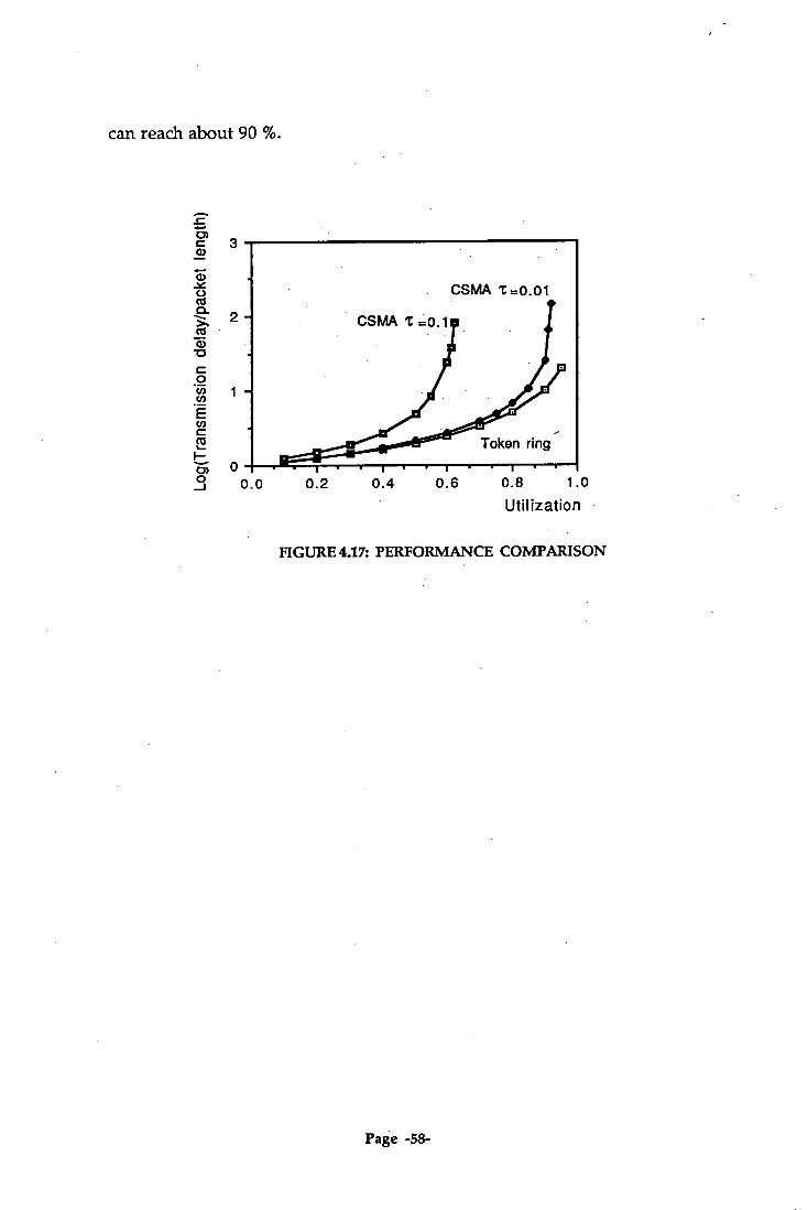
CSMA
CSMA t .0.1
Token ring
3
2
1
Log(
Tran
smiss
ion
delay
/pac
ket
leng
th)
can reach about 90 %.
0.0
0.2
0.4
0.6
0.8 1.0 Utilization
FIGURE 4.17: PERFORMANCE COMPARISON
Page -58-

Chapter 5
CONCLUSION
Both IEEE 802.5 and IEEE 802.3 are approved standards for Local
Area Networks. The interconnection of 802.5 LANs uses a technique
called Source Routing whereas the interconnection of 802.3 LANs uses a
technique called Transparent Bridging. Both standards have its
advantages and disadvantages, but IEEE 802.3 is the widely accepted
standard. The bridging techniques of these two LANs are incompatible
to one another. The interconnection of these different LANs has been
done using a converter or translating software in the bridge, such bridge
is commonly called an SR/TB. This incompatibility decreases the speed
and performance as described in Section 2.5.
The SRT bridge is a new bridging scheme that is presently being
developed and it works at MAC level. This bridge will act as a Source
Routing bridge for frames coming from Source Routing stations and
will act as a Transparent bridge for frames coming from Transparent
bridging stations. This bridge is introduced to overcome the
incompatibility problems of Transparent and Source Routing bridges. In
developing this bridge, many parameters were considered in order to
keep high performance. The parameters to be considered are service
availability, frame loss, frame misordering, frame duplication, transit
delay, frame lifetime, undetected frame error rate, maximum frame
length, user priority and throughput. In terms of speed, the SRT bridge
will be definitely faster than SR/TB bridge because it does not need any
software for converting data units from one bridging philosophy to
another. Of course this scheme can avoid the errors of conversion that
occurred in SR/TB.
Page -59-

In this project, computer simulation models are developed to
analyze the performance of Token Ring, Source Routing, IEEE 802.3 LAN
and Transparent Bridging. For Source Routing and Transparent Bridging,
there are three LANs serially connected. The SIMSCRIPT simulation is
used to analyze the performance under the assumption that 60 % of frames
will travel within a LAN and 40 % outside of the LAN.
The Token Ring has a deterministic performance and its utilization
can go up to nearly 100% utilization at the expense of transmission delay.
IEEE 802.3 LAN has a limited maximum utilization which depends on
end-to-end delay. The problem on IEEE 802.3 LAN is excentially one of
frame collisions. If end-to-end delay is longer then the probability of collision
is higher thus causing a higher transmiaaion delay. Because of the factor
of end-to-end delay, IEEE 802.3 LAN standard give a limitation for maximum
distance of end-to-end stations i.e. 2 km away. If the bus length does not
exceed 2 km then the maximum throughput can reach around 80-90 %
(see Figure 4.13 and 4.14).
If we compare the Token ring LAN and IEEE 802.3 LAN, the delay
in Token Ring is much higher than IEEE 802.3 LAN, (refer to the service
time calculation in Chapter 4), because in Token Ring we have to consider
the synchronization time in each station on the ring. If the number of
stations in the ring increases then the delay will increase linearly. Suppose
the number of stations is 25 and the average frame length is 1 Kilobyte.
According to the calculation in Chapter 4, the service time for Token Ring
will be 51.203 ms (see page 41) whereas for IEEE 802.3 LAN it will be 0.8192
ms (see page 52).
The delay of Source Routing and Transparent Bridging is very high.
It is caused by the low speed of the bridge i.e. 56 kbps, thus the delay in the
bridge is much higher than the delay in the LAN. If the speed of bridge is
same as the speed of the LAN, there would be no problem of frames
discarding caused by overflow of buffer capacity. In simulation of Source
Page -60-

Routing or Transparent Bridging, the delay of frame from any station in
LAN 1 to any station in LAN 3 is almost the same as the summation of
average delay in LAN 1, average delay in LAN 2, average delay in LAN 3,
and delay in the bridges. The delay in LAN 2 is much higher than the delay in LAN 1 or LAN 3 because LAN 2 is also responsible for passing the
frames from LAN 1 to LAN 3, keeping in mind the system comprises
three serially connected LANs. The important information here is that
the balance of delay or performance in each LAN must be about the same.
For Source Routing, if there is one ring in cascade building up a queue
then that ring becomes a critical path for any frame that has to follow such
ring. The performance of such Source Routing depends on the performance
of the worst ring. This problem can also occur in Transparent Bridging
and in such a case it becomes worse due to collisions.
Page -61-

REFERENCES
[1].Tanenbaum, Andrew S.,"Computer Network" 2nd Ed., Prentice-Hall,
1989.
[2].Schwartz, Mischa,"Telecommunication Network : Protocols, Modelling
and Analysis". Addison Wesley. 1987.
[3].Varghese, George and Perlman, Radia. "Transparent Interconnection
of Incompatible Local Area Networks Using Bridges". IEEE Journal
on Selected Area in Communication. Vol. 8 No 1 Jan. 1990.
[4].Backes, Floyd. "Transparent Bridges for Interconnection of IEEE 802
LANs". IEEE Network Vol. 2 No 1 Jan. 1988.
[5].Dixon, Roy C. and Pitt, Daniel A.,"Addressing, Bridging, and Source Routing". IEEE Network Vol. 2 No 1 Jan. 1988.
[6].Hamner,Claire M. and Samsen, Gerald R. "Source Routing Bridge
Implementation". IEEE Network Vol 2 No 1 Jan. 1988.
[7].Soha, Michael and Perlman, Radia. "Comparison of Two LAN Bridge
Approaches". IEEE Network Vol. 2 No 1 Jan. 1988.
[8].Zhang, Lida. "Comparison of Two Bridge Routing Approaches". IEEE
Network Vol. 2 No 1 Jan. 1988.
[9]. Bux, Werner. "Token-Ring Local-Area Networks and Their
Performances". Proceedings of The IEEE Vol. 77 No 2 Feb. 1989.
[10].Bux, Werner. "Local Area Subnetworks: A Performance Comparison".
IEEE Transactions on Communications, Vol. Com-29, no 10, October
1991.
[11].SS Lam. "A Carrier Sense Multiple Access Protocol for Local Networks".
IEEE Computer Network,Vol 4, 1980.
Page -62-

[12]. IBM Handbook."Source Routing Transparent Bridging 802.1d
SRT".1990.
[13].IBM. "Local Area Networks Concepts and Products". 1989.
[14]. Stallings, William. " Data and Computer Communications". 3rd Ed.
Macmillan Publishing Co., 1991.
[15]. IBM. "IEEE 802.3 Local Area Network Considerations". Doc. No. GG-
9422-0. January 1988.
[16]. IBM. "Performance Report of IBM Token Ring Network; Bridge
Program 2.1". Doc. No. ZZ63-05000-00. January 1990.
[17]. IBM. "Local and Metropolitan Area Network; P802.1d MAC Bridges".
Doc. No. P802.1d/D9. July 1989.
[18]. The IEEE Inc. "802.5 Local Area Networks; Token Ring Access Method".
September 1986.
Page -63-

APPENDICES
1. Results for Single Ring
Utilization Throughput Delay No. frame waiting
0.092 0.368 53.783 0.010 0.206 0.824 65.048 0.056 0.360 1.440 78.952 0.185 0.510 2.040 100.863 0.489 - 0.661 2.644 152.304 1.307 0.813 3.252 283.503 3.961 0.914 3.656 457.886 7.241 0.970 3.880 1377.103 24.980
2. SIMSCRIPT Programs for Token Ring
preamble
" This section is used for declaration of Process, Resources, Global Variable " LAN represents a Resource or Server " "message" represents a packet or customer
processes include ring_generator,message resources include LAN
define departtime as real variable define totaldelay as real variable
accumulate ring_utilization as the average of n.x.LAN accumulate num_waiting as the average of n.q.LAN tally meandelay as the average of totaldelay
define station, maxstation, value as integer variable define lamda, duration as real variable define servicetime as real variable
"Time systems are seconds, miliseconds or microseconds
Page -64-

define .seconds to mean days define .miliseconds to mean hours define .microseconds to mean minutes
end
" ***************************************************************** main ..***************************************************************** " This is a main program to read data, activate simulation and , print out the output
define length as real variable
let hours.v = 1000 let minutes.v = 1000
print 1 line thus lamda service-time length read lamda,servicetime,length print 1 line with lamda,servicetime,length thus
let duration = ((length)*1000)/hours.v
create every LAN(1) let u.LAN(1) = 1
activate a ring_generator now start simulation
print 4 lines with meandelay*1000,ring_utilization,num_waiting as follows
meandelay utilization number of waiting
end
Page -65-

process ring_generator .*****************************************************************
"This section is to generate the packet within duration time
until time.v > duration do activate a message now wait exponentiall(1/lamda,l) .miliseconds
loop end
11 ******* *********** **** ******************** * **** ****************** process message
1 ***************************************************************** "This section is actually a packet that requests the resources, if the "resource is busy then this packet will be schedulled automatically by " SIMSCRiPT system
define arrival as real variable arrival = time.v request 1 LAN(1) work exponential.f(servicetime,l) .miliseconds relinquish 1 LAN(1) let totaldelay = time.v - arrival
end
Page -66-

3. Results for Source Routing
Note : Delay11 = A delay within LAN1 Delay13 = A delay from any station in LAN1 to any station in LAN3
(1) Delay 11
(2) Delay 12
(3) Delay 13
(4) Delay 21
(5) Delay 22
(6) Delay 23
57.975 312.742 540.779 339.977 61.918 313.693 . 66.287 364.665 683.837 365.732 77.315 378.804 70.217 400.556 762.161 398.185 81.080 420.121 79.086 491.867 861.182 516.782 99.800 483.385 90.290 668.133 1280.260 660.225 113.727 752.995
107.555 1206.275 1997.096 1107.948 145.984 1051.813 113.209 2221.796 4878.365 2190.138 182.470 2863.393
continue (7 )
Delay 31 (8)
Delay 32 (9)
Delay 33 (10)
p - ring1 (11)
p - ring2 (12)
p - ring 3 559.585 330.060 58.089 0.146 0.179 0.138 669.808 362.709 68.396 0.213 0.286 0.220 738.280 434.751 71.725 0.286 0.364 0.292 915.431 495.292 79.373 0.367 0.464 0.357
1328.006 757.922 92.973 0.418 0.538 0.440 2029.293 1054.008 114.345 0.517 0.649 0.521 5007.664 2907.617 125.287 0.572 0.720 0.579
(continue )
(13) p -bridge1
(14) p -bridge2
(15) 2t,
(16) Throughput
0.231 0.221 0.002 0.716 0.342 0.359 0.003 1.144 0.440 0.467 0.004 1.456 0.568 0.570 0.005 1.856 0.695 0.733 0.006 2.152 0.836 0.846 0.007 2.596 0.931 0.938 0.008 2.880
Page -67-
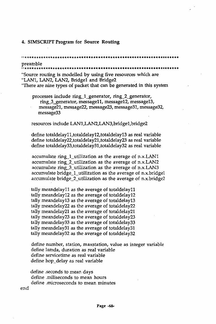
4. SIMSCRIPT Program for Source Routing
1 ***************************************************************** preamble
"Source routing is modelled by using five resources which are "LAN1, LAN2, LANZ Bridgel and Bridge2 "There are nine types of packet that can be generated in this system
processes include ring_1_generator, ring_2_generator, ring_3_generator, messagell, message12, message13, message21, message22, message23, message31, message32, message33
resources include LAN1,LAN2,LAN3,bridgel,bridge2
define totaldelay11,totaldelay12,totaldelay13 as real variable define totaldelay22,totaldelay21,totaldelay23 as real variable define totaldelay33,totaldelay31,totaldelay32 as real variable
accumulate ring_l_utilization as the average of n.x.LAN1 accumulate ring_2_utilization as the average of n.x.LAN2 accumulate ring_3_utilization as the average of n.x.LAN3 accumulate bridge_1_utilization as the average of n.x.bridgel accumulate bridge_2_utilization as the average of n.x.bridge2
tally meandelayll as the average of totaldelayll tally meandelay12 as the average of totaldelay12 tally meandelay13 as the average of totaldelay13 tally meandelay22 as the average of totaldelay22 tally meandelay21 as the average of totaldelay21 tally meandelay23 as the average of totaldelay23 tally meandelay33 as the average of totaldelay33 tally meandelay31 as the average of totaldelay31 tally meandelay32 as the average of totaldelay32
define number, station, maxstation, value as integer variable define lamda, duration as real variable define servicetime as real variable define hop_delay as real variable
define .seconds to mean days define .miliseconds to mean hours define .microseconds to mean minutes
end
Page -68-

I I *****************************************.************************ main
"This is the main program to activate the simulation
define length as real variable
let hours.v = 1000 let minutes.v = 1000
print 1 line thus lamda service-time maxsation hop-delay length read lamda,servicetime,maxstation,hop_delay, length print 1 line with lamda,servicetime,maxstation,hop_delay,length thus *.*** *
.*** *** *.*** ***
let duration = ((length)*1000)/hours.v
create every LAN1(1) let u.LAN1(1) = 1
create every LAN2(1) let u.LAN2(1) = 1
create every LAN3(1) let u.LAN3(1) = 1
create every bridgel(1) let u.bridgel(1) = 1
create every bridge2(1) let u.bridge2(1) = 1
activate a ringi_generator now activate a ring_24enerator now activate a ring_3_generator now start simulation
print 2 lines with meandelayll*1000, meandelay12*1000, meandelay13*1000 as follows meandelayll meandelay12 meandelay13 (in miliseconds)
**.*** **.*** ** ***
print 2 lines with meandelay21*1000, meandelay22*1000, meandelay23*1000 as follows meandelay21 meandelay22 meandelay23
** *** ** *** **.***
Page -69-

print 3 lines with meandelay31*1000, meandelay32*1000, meandelay33*1000 as follows meandelay31 meandelay32 meandelay33
** *** **.***
print 1 line with ring_l_utilization,ring_2_utilization, ring_3_utilization,bridge_1_utilization,
bridge_2_utilization as follows Lan1 : *.*** Lan2 : *.*** Lan3 *.*** Bridgel /2: *•*** * ***
end
process ring_l_generator ,i***************************************************************** "This process is to generate packets in any station in ring 1. The packet "may travel inside or outside the ring according to a random number.
until time.v > duration do for station = 1 to maxstation do
let value = randii(1,100,1) if value < 61,
activate a message11 now else
if value < 81, activate a message12 now
else activate a messagel3 now
always always wait exponential.f(1 /lamda,l) milliseconds
loop loop
end
process ring_2_generator I ***************************************************************** "This section generates packets in any station in ring 2
until time.v > duration do for station = 1 to maxstation do
let value = randil(1,100,1) if value < 61,
activate a message22 now else
Page -70-

if value < 81, activate a message21 now
else activate a message23 now
always always wait exponentiall(1 /lamda,l) .miliseconds
loop loop
end
process ring_3_generator *****************************************************************
"This section generates packets in ring 3
until time.v > duration do for station = 1 to maxstation do
let value = randi.f(1,100,1) if value < 61,
activate a message33 now else
if value < 81, activate a message31 now
else activate a message32 now
always always wait exponential.f(1 /larnda,l) .miliseconds
loop loop
end
I I************ * ******************** ********************* * ********** process messagell I t***************************************************************** "This message will travel within ring 1
define departtimel1 as real variable departtimel1 = time.v request 1 LAN1(1) work exponential.f(servicetime,l) .miliseconds relinquish 1 LAN1(1) let totaldelay11 = time.v - departt-ime11
end
Page -71-

**** ************************************************************* process messagel2
1 ***************************************************************** "This packet will travel from station in LAN 1 to LAN 2
define departtimel2 as real variable departtime12 = time.v
request 1 LAN1(1) work exponentiaLf(servicetime,1) .miliseconds relinquish 1 LAN1(1)
request 1 bridgel (1) work exponentialf(hop_delay,1) aniliseconds relinquish 1 bridgel(1)
request 1 LAN2(1) work exponentiaLf(servicetime,l) .miliseconds let totaldelay12 = time.v - departtimel2 relinquish 1 LAN2(1)
end
process message13 I I **** * ******************************************** ******** ******** "This packet will travel from ring 1 to station in ring 3
define departtime13 as real variable departtimel3 = time.v
request 1 lan1(1) work exponentiall(servicetime,l) .miliseconds relinquish 1 lanl (1)
request 1 bridgel(1) work exponential.f(hop_delay,1) .miliseconds relinquish 1 bridgel (1)
request 1 lan2(1) work exponentiall(servicetime,1) .miliseconds relinquish 1 lan2(1)
request 1 bridge2(1) work exponentiall(hop_delay,l) .miliseconds relinquish 1 bridge2(1)
Page -72-
request 1 lan3(1) work exponentiall(servicetime,l) aniliseconds let totaldelay13 = (time.v - departtime13) relinquish 1 lan3(1)
end
process message21
"From ring 2 to station in ring 1
define departtime21 as real variable departtime21 = time.v
request 1 LAN2(1) work exponentiall(servicetime,l) .miliseconds relinquish 1 LAN2(1)
request 1 bridgel(1) work exponential.f(hop_delay,1) .miliseconds relinquish 1 bridgel(1)
request 1 LAN1(1) work exponential.f(servicetime,l) .miliseconds let totaldelay21 = (time.v - departtime21) relinquish 1 LAN1(1)
end
process message22 *****************************************************************
"This packect will travel from a station to another station in LAN 2
define departtime22 as real variable departtime22 = time.v
request 1 LAN2(1) work exponential.f(servicetime,l) .miliseconds relinquish 1 LAN2(1)
let totaldelay22 = time.v - departtime22 end
Page -73-

l***************************************************************** process message23 t*****************************************************************
"From station in LAN 2 to LAN 3
define departtime23 as real variable depart-time23 = time.v
request 1 LAN2(1) work exponential.f(servicetime,1) .miliseconds relinquish 1 LAN2(1)
request 1 bridge2(1) work exponential.f(hop_delay,1) .miliseconds relinquish 1 bridge2(1)
request 1 LAN3(1) work exponential.f(servicefime,1) .miliseconds let totaldelay23 = (time.v - departtime23) relinquish 1 LAN3(1)
end
t*****************************************************************
process message31
"This packet will travel from a station in ring 3 to any station in ring 1
define departtime31 as real variable departtime31 = time.v
request 1 LAN3(1) work exponential.f(servicetime,l) .miliseconds relinquish 1 LAN3(1)
request 1 bridge2(1) work exponentialf(hop_delay,1) .miliseconds relinquish 1 bridge2(1)
request 1 LAN2(1) work exponential.f(servicetime,l) .miliseconds relinquish 1 LAN2(1)
request 1 bridgel (1) work exponentiall(hop_delay,l) .miliseconds relinquish 1 bridgel(1)
Page -74-

request 1 LAN1(1) work exponentiall(servicetime,l) .miliseconds let totaldelay31 = (time.v - departtime31) relinquish 1 LAN1(1)
end
process message32 *****************************************************************
"From ring 3 to ring 2
define departtime32 as real variable departtime32 = time.v
request 1 LAN3(1) work exponential.f(servicetime,1) .miliseconds relinquish 1 LAN3(1)
request 1 bridge2(1) work exponentiall(hop_delay,l) miliseconds relinquish 1 bridge2(1)
request 1 LAN2(1) work exponential.f(servicetime,1) .miliseconds let totaldelay32 = (time.v - departtime32) relinquish 1 LAN2(1)
end
I ***************************************************************** process message33 *****************************************************************
"Within LAN 3
define departtime33 as real variable departtime33 = time.v
request 1 LAN3(1) work exponential.f(servicetime,l) .miliseconds relinquish 1 LAN3(1) let totaldelay33 = time.v - departtime33
end
Page -75-
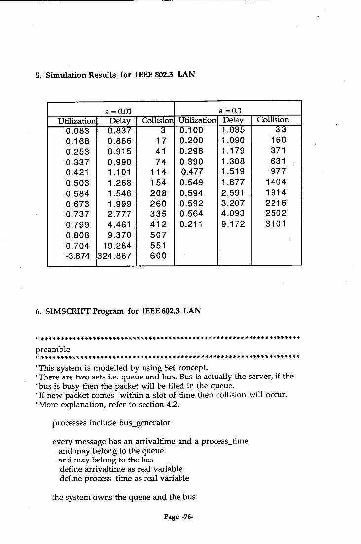
5. Simulation Results for IEEE 802.3 LAN
a = 0.01 a=0.1 Utilization Delay Collision Utilization Delay Collision
0.083 0.837 3 0.100 1.035 33 0.168 0.866 17 0.200 1.090 160 0.253 0.915 41 0.298 1.179 371 0.337 0.990 74 0.390 1.308 631 0.421 1.101 114 0.477 1.519 977 0.503 1.268 154 0.549 1.877 1404 0.584 1.546 208 0.594 2.591 , 1914 0.673 1.999 260 0.592 3.207 2216 0.737 2.777 335 0.564 4.093 2502 0.799 4.461 412 0.211 9.172 3101 0.808 9.370 507 0.704 19.284 551 -3.874 324.887 600
6. SIMSCRIPT Program for IEEE 802.3 LAN
1 , ****************************************************** * **********
preamble 1 , * ** ******* ********* ** ******* ********* ********* ** ******* ** ******* * "This system is modelled by using Set concept. "There are two sets i.e. queue and bus. Bus is actually the server, if the "bus is busy then the packet will be filed in the queue. "If new packet comes within a slot of time then collision will occur. "More explanation, refer to section 4.2.
processes include bus_generator
every message has an arrivaltime and a process_time and may belong to the queue and may belong to the bus define arrivaltime as real variable define process_time as real variable
the system owns the queue and the bus
Page -76-

define totaldelay as real variable
accumulate utilization as the average of n.bus accumulate meandelay as the average of totaldelay
define lamda, duration as real variable define servicetime as real variable
define .seconds to mean days define .miliseconds to mean hours define .microseconds to mean minutes define frame.number and collision.number as real variable define delay as real variable
define .arriving to mean 1 define .leaving to mean 2
define .idle to mean 0 define .busy to mean 1 define .collision to mean 2
end
main
"This is the main body of the program. "This section is used to read data, start simulation and write results.
define length as real variable
let hours.v = 1000 let minutes.v = 1000
print 1 line thus lamda service-time end-to-end delay length read lamda,servicetime,delay,length
print 1 line with lamda,servicetime,delay,length thus *.*** *.*** *.*** * *** let duration = ((length)*1000)/hours.v
activate a bus_generator now start simulation
print 3 lines with meandelay*1000,utilization,utilization-
Page -77-

(collision.numbeemeandelay/ length), frame.number,collision.number as follows
meandelay utilization real.util frames Collision * *** * *** * *** *** ***
end
u* ***** * ***** * **** *********** ***** * ***** * ***** ********** ****** **** routine bus.status given new.message and action yielding status t********* ****** ***** * ***** * **** * ********** *********** ****** * **** *
"This routine is used for checking the status of bus/server. "This status can be idle, busy or collision.
define action, status,new.message, other.message and message as integer variable
define retransmit.delay as real variable
if action = .arriving if bus is not empty
let other.message = f.bus interrupt message called other.message let collision.time = time.v - time.a(other.message) resume message called other.message if collision.time < delay/1000 let status = .collision let retransmit.delay = (randil(1,10,1)*2*delay) wait retransmit.delay .miliseconds
else let status = .busy
always else
file this new.message in the bus let status = .idle
always else
if queue is not empty remove the first message from the queue file this message in the bus reactivate this message now
always let status = .idle
always return
end
Page -78-
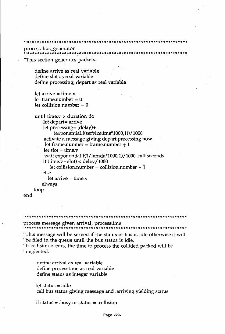
***************************************************************** process bus_generator
"This section generates packets.
define arrive as real variable define slot as real variable define processing, depart as real variable
let arrive = time.v let frame.number = 0 let collision.nu.mber = 0
until time.v > duration do let depart= arrive let processing= (delay)+
(exponential.f(servicetime*1000,1))/1000 activate a message giving depart,processing now let frame.number = frame.number + 1 let slot = time.v wait exponential.f(1/lamda*1000,1)/1000 .miliseconds if (time.v - slot) < delay/1000
let collision.number = collision.number + 1 else
let arrive = time.v always
loop end
10 ************. ***************************************************** process message given arrival, processtime i*****************************************************************
"This message will be served if the status of bus is idle otherwise it will "be filed in the queue until the bus status is idle. "If collision occurs, the time to process the collided packed will be "neglected.
define arrival as real variable define processtime as real variable define status as integer variable
let status = .idle call bus.status giving message and .arriving yielding status
if status = .busy or status = .collision
Page -79-
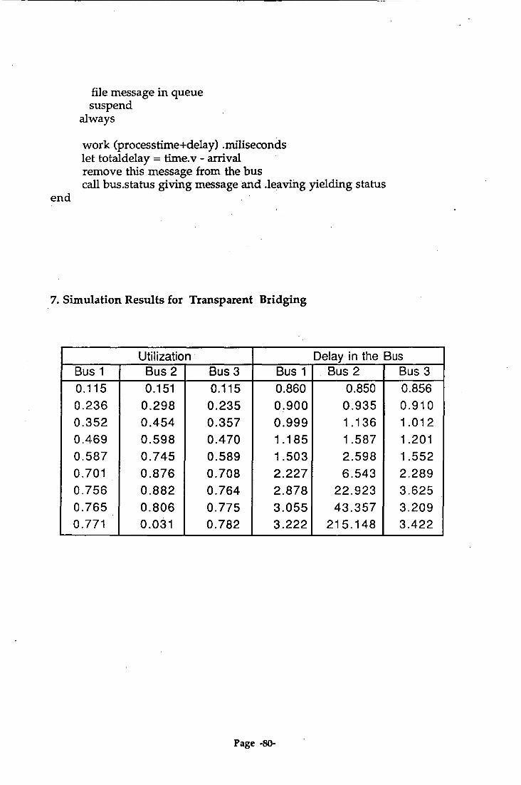
file message in queue suspend
always
work (processtime+delay) .miliseconds let totaldelay = time.v - arrival remove this message from the bus call bus.status giving message and .leaving yielding status
end
7. Simulation Results for Transparent Bridging
Utilization Delay in the Bus Bus 1 Bus 2 Bus 3 Bus 1 Bus 2 Bus 3 0.115 0.151 0.115 0.860 0.850 0.856 0.236 0.298 0.235 0.900 0.935 0.910 0.352 0.454 0.357 0.999 1.136 1.012 0.469 0.598 0.470 1.185 1.587 1.201 0.587 0.745 0.589 1.503 2.598 1.552 0.701 0.876 0.708 2.227 6.543 2.289 0.756 0.882 0.764 2.878 22.923 3.625 0.765 0.806 0.775 3.055 43.357 3.209 0.771 0.031 0.782 3.222 215.148 3.422
Page -80-

(Continue..)
Number of Collision Delay accross the Bus Bus 1 Bus 2 Bus 3 Bus1 & Bus2 Bus1 & Bus3 Bus2 & Bus3
1 4 9 149.883 296.884 147.841 16 15 21 146.324 297.663 152.274 31 39 37 150.561 297.935 148.510 65 60 65 150.785 299.160 149.962 -
106 101 103 151.564 301.628 152.662 157 143 141 156.981 306.127 155.689 172 164 164 174.903 324.875 172.895 177 169 165 194.779 344.734 193.293
187 _ 180 173 _ 367.606 519.475 367.016
8. SIMSCRIPT Programs for Transparent Bridging
preamble 1 *****************************************************************
"This program simulates the Transparent Bridging for three buses "serially connected. This simulation also uses a set concept where "the packet will be filed in the queue if the bus is busy
processes include bus_generatorl,bus_generator2,bus_generator3
every messagell has an arrivaltimell and may belong to the queuel and may belong to the busl
every message22 has an arrivaltime22 and may belong to the queue2 and may belong to the bus2
every message33 has an arrivaltime33 and may belong to the queue3
Page -81-
and may belong to the bus3
define arrivaltime11,arrivaltime22,arrivaltime33 as real variable
the system owns the queue1,the queue2,the queue3,the busl, the bus2 and the bus3
define totaldelayll,totaldelay22,totaldelay33 as real variable define bridgedelayl and bridgedelay2 as real variable
accumulate utilization1 as the average of n.bus1 accumulate utilization2 as the average of n.bus2 accumulate utilization3 as the average of n.bus3
accumulate meandelayll as the average of totaldelay11 accumulate meandelay22 as the average of totaldelay22 accumulate meandelay33 as the average of totaldelay33
accumulate bridge.delayl as the average of bridgedelayl accumulate bridge.delay2 as the average of bridgedelay2
define lamda, duration as real variable define servicetime as real variable
define .seconds to mean days define .miliseconds to mean hours define .microseconds to mean minutes
define frame.numberl,frame.number2 and frame.number3 as integer variable
define collision.numberl,collision.number2, collision.number3 as integer variable
define delayl,delay2,delay3 as real variable
define .arriving to mean I define .leaving to mean 2
define .idle to mean 0 define .busy to mean 1 define .collision to mean 2
end
I ******* * **** * ****************************** * *** *** ********** * **** main .*****************************************************************
"This is the main body of the program
Page -82-

define length as real variable
let hours.v = 1000 let minutes.v = 1000
print 1 line thus lamda service-time end-to-end delay(1,2,3) length read lamda,servicetime,delayl,delay2,delay3,1ength
print 1 line with lamda,servicetime,delay1,delay2,delay3,1ength thus *.*** *.*** * *** * *** * ***
let duration = ((length)*1000)/hours.v
activate a bus_generatorl now activate a bus_generator2 now activate a bus_generator3 now start simulation
print 3 lines with meandelayll*1000,utilizationtutilization1- (collision.number1*meandelayl 1 /length), frame.numberl,collision.numberl as follows
meandelay11 utilization1 real.util1 frames1 Collision1 *.*** * *** * *** *** ***
print 2 lines with meandelay22*1000,utilization2,utilization2- (collision.number2*meandelay22/1ength), frame.number2,collision.number2 as follows
meandelay22 utilization2 real.util2 frames2 Collision2 *.*** *.*** * *** *** ***
print 3 lines with meande1ay33*1000,utilization3,uti1ization3- (collision.number3*meandelay33 /length), frame.number3,collision.number3 as follows
meandelay33 utilization3 real.util3 frames3 Collision3 *.*** * *** *.*** *** ***
print 2 lines with (meandelayll+meandelay22)*1000+bridge.delay1, (meandelayll+meandelay22+meandelay33)*1000+ bridge.delay1+ bridge.delay2, (meandelay22+meandelay33)*1000+bridge.delay2 as follows
delay12 or21 delay13 or 31 delay23 or 32 *.*** *.*** *.***
end
Page -83-

"***************************************************************** routine bus.statusl given new.message and action yielding status "***************************************************************** "This routine is used for checking the status of bus 1
define action, status,new.message and other.message as integer variable
define retransmit.delayl as real variable define collision.tirnel as real variable
if action = .arriving if busl is not empty
let other.message = f.busl interrupt messagell called other.mess age let collision.timel = time.v - time.a(other.message) resume messagell called other.message if collision.timel < delayl /1000 let status = .collision let retransmit.delayl = (randi.f(1,10,1)*2*delayl) wait retransmit.delayl miliseconds
else let status = .busy
always else
file this new.message in the busl let status = .idle
always else
if queuel is not empty remove the first mess agel 1 from the queuel file this messagell in the busl reactivate this messagel 1 now
always let status = .idle
always return
end
routine bus.status2 given new.message and action yielding status "***************************************************************** "This routine is used for checking the status of bus 2
define action, status,new.message and other.message
Page -84-

as integer variable define retransmit.delay2 as real variable define collision.time2 as real variable
if action = .arriving if bus2 is not empty
let other.message = f.bus2 interrupt message22 called other.message let collision.time2 = time.v - time.a(other.message) resume message22 called other.message if collision.time2 < delay2/1000
let status = .collision let retransmit.delay2 = (randil(1,10,1) 42*delay2) wait retransmit.delay2 .miliseconds
else let status = .busy
always else
file this new.message in the bus2 let status = .idle
always else
if queue2 is not empty remove the first message22 from the queue2 file this message22 in the bus2 reactivate this message22 now
always let status = .idle
always return
end
I 1***** ***** ********* ****** ************ ***** ** **** ** *** * ** ** ** * ** * * routine bus.status3 given new.message and action yielding status
I ***************************************************************** "This routine is used for checking the status of bus 3
define action, status,new.message and other.message as integer variable
define retransmit.delay3 as real variable define collision.time3 as real variable
if action = .arriving if bus3 is not empty
Page -85-
as integer variable define retransmit.delay2 as real variable define collision.time2 as real variable
if action = .arriving if bus2 is not empty
let other.message = f.bus2 interrupt message22 called other.message let collision.time2 = time.v - time.a(other.message) resume message22 called other.message if collision.time2 < delay2/1000
let status = .collision let retransmit.delay2 = (randi.f(1,10,1)*2*delay2) wait retransmit.delay2 .miliseconds
else let status = .busy
always else
file this new.message in the bus2 let status = .idle
always else
if queue2 is not empty remove the first message22 from the queue2 file this message22 in the bus2 reactivate this message22 now
always let status = .idle
always return
end
I ,***************************************************************** routine bus.status3 given new.message and action yielding status
"This routine is used for checking the status of bus 3
define action, status,new.message and other.message as integer variable
define retransmit.delay3 as real variable define collision.time3 as real variable
if action = .arriving if bus3 is not empty
Page -85-

let other.message = f.bus3 interrupt message33 called other.message let collision.tirne3 = time.v - time.a(other.message) resume message33 called other.message if collision.time3 < delay3/1000
let status = .collision let retransmit.delay3 = (randil(1,10,1)*2*delay3) wait retransmit.delay3 .miliseconds
else let status = .busy
always else
file this new.message in the bus3 let status = .idle
always else
if queue3 is not empty remove the first message33 from the queue3 file this message33 in the bus3 reactivate this message33 now
always let status = .idle
always return
end
t***************************************************************** process bus_generator1 ************************* ****** ** *** ***************** ************
"This process wil generate packets in bus 1
define value as integer variable define arrive as real variable define slot as real variable define depart as real variable
let arrive = time.v let frame.numberl = 0 let collision.number1 = 0
until time.v > duration do let frame.numberl = frame.number1 + 1 let value = randi.f(1,100,1) let depart= arrive
if value < 60
Page -86-

activate a message11 giving depart now else
if value <80 activate a messagel1 giving depart now let bridgedelay1 = exponential.f(146.286,1) activate a message22 giving depart now
else activate a messagel1 giving depart now let bridgedelay1 = exponentiall(146.286,1) activate a message22 giving depart now let bridgedelay2 = exponentiali(146.286,1) activate a message33 giving depart now
always always
let slot = time.v wait exponential.f(1/1amda*1000,1)/1000 .miliseconds
if (time.v - slot) < delay1/1000 let collision.numberl = collision.numberl + 1
else let arrive = time.v
always loop
end
I I****************************** ************** ********************* process bus_generator2 I***************************************************************** This process will generate packets in bus 2
define value as integer variable define arrive as real variable define slot as real variable define depart as real variable
let arrive = time.v let frame.number2 = 0 let collision.number2 = 0
until time.v > duration do let frame.number2 = frame.number2 + 1 let value = randi.f(1,100,1) let depart= arrive
if value < 60
Page -87-
activate a message22 giving depart now else
if value <80 activate a message22 giving depart now let bridgedelay1 = evonentiall(146.286,1) activate a messagell giving depart now
else activate a message22 giving depart now let bridgedelay2 = exponentiall(146.286,1) activate a message33 giving depart now
always always
let slot = time.v wait exponential.f(1/1amda*1000,1)/1000 .miliseconds
if (time.v - slot) < delay2/1000 let collision.number2 = collision.number2 + 1
else let arrive = time.v
always loop
end
,1 ***************************************************************** process bus_generator3 I 1 *** * ********* ******************************** **** ************* * ** "This process will generate packets in bus 3
define value as integer variable define arrive as real variable define slot as real variable define depart as real variable
let arrive = time.v let frame.number3 = 0 let collision.number3 = 0
until time.v > duration do let frame.number3 = frame.number3 + 1 let value = randi.f(1,100,1) let depart= arrive
if value < 60 activate a message33 giving depart now
else
Page -88-

if value < 80 activate a message33 giving depart now let bridgedelay2 = exponentiall(146.285,1) activate a message22 giving depart now
else activate a message33 giving depart now let bridgedelay2 = exponentiall(146.285,1) activate a message29 giving depart now let bridgedelay1 = exponential.f(146.285,1) activate a message11 giving depart now
always always
let slot = time.v wait exponentiall(1 /lamda*1000,1)/1000 .miliseconds
if (time.v - slot) < delay3/1000 let collision.number3 = collision.number3 + 1
else let arrive = time.v
always loop
end
I ***************************************************************** process message11 given arrival " ***************************************************************** "This message will travel within bus 1
define arrival as real variable define processing as real variable define status as integer variable
let processing= (delay1)+ (exponential. f(servicetime*1000,1))/ 1000
let status = .idle call bus.statusl giving message11 and .arriving yielding status
if status = .busy or status = .collision file message11 in queue1 suspend
always work (processing+delayl) .miliseconds let totaldelay11 = time.v - arrival remove this message11 from the busl call bus.status1 giving message11 and .leaving yielding status
Page -89-

end
t I ***************************************************************** process message22 given arrival
"This message will travel within bus 2
define arrival as real variable define processing as real variable define status as integer variable
let processing= (delay2)+ (exponential.f(servicetime*1000,1))/ 1000
let status = .idle call bus.status2 giving message22 and .arriving yielding status
if status = .busy or status = .collision file message22 in queue2 suspend
always work (processing+delay2) .miliseconds let totaldelay22 = time.v - arrival remove this message22 from the bus2 call bus.status2 giving message22 and .leaving yielding status
end
***************************************************************** process message33 given arrival *****************************************************************
"This message will travel within bus 3
define arrival as real variable define processing as real variable define status as integer variable
let processing= (delay3)+ (exponential.f(servicetimen 000,1))! 1000
let status = .idle call bus.status3 giving message33 and .arriving yielding status
if status = .busy or status = .collision file message33 in queue3 suspend
always work (processing+delay3) .miliseconds
Page -90-
let totaldelay33 = time.v - arrival remove this message33 from the bus3 call bus.status3 giving message33 and .leaving yielding status
end
Page -91-