masport inbuilt gas fireplace - 1€¦ · masport inbuilt gas fireplace - 4 - piccolo wiring...
TRANSCRIPT

Masport Inbuilt Gas Fireplace - 1 -

Masport Inbuilt Gas Fireplace - 2 -
MASPORT INBUILT GAS FIRE
TO THE NEW OWNERCongratulations! You are the owner of a state-of-the-art Gas Fire by Masport. The MasportInbuilt Gas Fires have been approved by the Australian Gas Association for both safety andefficiency.
Please take time to acquaint yourself with these instructions and the many features of yourMasport Fire.
This book contains important information. Please keep it in a safe place forfuture reference.
Sofia/Madrid Piccolo
THE INSTRUCTIONS IN THIS MANUAL APPLY TO;MASPORT INBUILT GAS FIRES– PICCOLO, SOFIA AND MADRID
Piccolo Sofia & Madrid - EISEIS => Electronic Ignition System.
363
11
6
590
964
GAS INLETCONNECTIONPICCOLO
67
2
56
0
56
3
63
149
477
433
GAS INLETCONNECTIONEIS
79
64

Masport Inbuilt Gas Fireplace - 3 -
TABLE OF CONTENTS
Contents Page
Installation Requirements
Wiring Diagrams ........................................4Safety .... ...................................................5Gas Pipe Testing .......................................5Important requirements ..............................5Specifications.............................................5
Installation Instructions
Electrical Requirements ............................6Installation Sequence ................................6Installation Procedure ................................7Clearances to Combustibles ......................7Flue System...............................................8Fire Installation ..........................................8Combustion & Ventilation Air .....................8Gas Connection .........................................8Fascia Installation – Sofia & Madrid ..........9
- Piccolo.....................10Glass Removal – Flush Front ..................11
- Bay Front..................11
Contents Page
Log & Ember Placement...........................12Gas Pressure Test ...................................12Optional Wall Thermostat ........................13Optional Remote Control..........................13
Operating Instructions
Operating Instructions..............................13Lighting Procedure...................................13Shutdown Procedure................................14The First Few Fires ..................................14Fan Operation ..........................................14Normal Operating Sounds of
Gas Appliances...................................15
Maintenance
General Maintenance...............................15Servicing .................................................15Log Replacement .....................................16Glass Gasket............................................16Gold Plated Trim ......................................16Glass Replacement..................................16Fan Maintenance .....................................16NG to LPG Conversion ............................17Cleaning Instructions ...............................17Troubleshooting .......................................18

Masport Inbuilt Gas Fireplace - 4 -
PICCOLO WIRING DIAGRAM
SWITCH
FAN
BROWN BRN
YEL/GN
PICCOLO FAN WIRING DIAGRAM — TWO SPEED
BLUE BLUE
YEL/GNGREEN
FANADAPTOR
LOOM FANSWITCH LOOMMAINS LEAD588068 590226 590227 586174
BLUEWHITE
ORANGERED WHITE
BROWN
SIX PIN PLUG AND SOCKET
CONNECTORS
CONNECTORS
EARTH POST
RED
ORANGE
BLUEBLACK
590456
If the supply cord is damaged, it must be replaced by the manufacturer or its service agent or a similarlyqualified person in order to avoid a hazard.
EIS WIRING DIAGRAM
VALVE
FLAME SENSORSPARKELECTRODE
FAN
THERMODISC
EARTHELECTRODE
FASCIAEARTHWIRE
CONTROLBOX
THERMO-STAT LINK
EIS SCHEMATIC ELECTRICAL LAYOUT
CONTROLPANEL
MAINS IN
9 PIN PLUGMODULATORLEAD
6 PIN PLUG
Blue
Yel
Vi
Red
Blk
Blk
VALVE LEAD
FIREOFF/ON
FIRELO/HI
FANLO/OFF/HI
If the supply cord is damaged, it must be replaced by the manufacturer or its service agent or a similarlyqualified person in order to avoid a hazard.

Masport Inbuilt Gas Fireplace - 5 -
IMPORTANT:SAVE THESE INSTRUCTIONS
The Masport Gas Fire must be installed in accordancewith these instructions. Carefully read all theinstructions in this manual first. Consult the "authorityhaving jurisdiction" to determine the need for a permitprior to starting the installation.
Note: Failure to follow these instructions couldcause a malfunction of the heater, whichcould result in death, serious bodily injury,and/or property damage. Failure to followthese instructions may also void your fireinsurance and/or warranty.
WARNING.InstallationInstallation must be carried out by a registered installerwho, on completion of the installation, must issue acertificate of compliance, in accordance with nationaland/or local codes. If a certificate of compliance is notissued then the Masport warranty may be void.
Warranty Repair & Annual ServicingWarranty repair work must be carried out by arecognised Masport gas fire Technician. It isrecommended that recognised Masport gas fireTechnicians are also used to carry out annual servicingrequirements (particularly during the warranty period).For contact details of authorised Masport Techniciansin your locality, please contact the retailer from whomthe appliance was purchased.
The heater must be installed according to theseinstructions and in compliance with all relevantbuilding, gas-fitting, electrical and other StatutoryRegulations (eg. AS 5601 (AG-601), NZS 5261). Anyshortcomings in the appliance and flue installation willbe the responsibility of the installer, and Masport Ltdwill not be accountable for any such failings or theirconsequences.
This appliance must not be installed in a mobile home.
The appliance must be checked and serviced yearly byan Authorised Technician.
FOR YOUR SAFETY
This appliance requires air for proper combustion.Always provide adequate combustion and ventilationair.
The guard is fitted to this appliance (Australia only) toreduce the risk of fire or injury from burns and no partof it should be permanently removed. For the
protection of young children or the infirm, a secondaryguard is required.
Do not place articles on or against this appliance.Do not use or store flammable materials near thisappliance.Do not spray aerosols in the vicinity of this appliancewhile it is in operation.
GAS PIPE TESTING
The appliance must be isolated from the gas supplypiping system by closing its individual manual shutoffvalve (not supplied with heater) during any pressuretesting of the gas supply piping system at testpressures equal to or greater than 6 kPa.
SPECIFICATIONS
Gas Consumption: 35MJ/h
Fuel: Natural Gas or LPGElectrical: 230-250 volts AC systemFan: 2 speedLogs: Ceramic fibre, 6 per set
Before installation commences, check the data plateon the appliance to verify that it is the correct type tosuit your gas and also that the gas consumption rate iscorrect for your application.
IMPORTANT REQUIREMENTS
Installation must be carried out by a registered installerwho, on completion of the installation, must issue acertificate of compliance, in accordance with nationaland/or local codes. If a certificate of compliance is notissued then the Masport warranty may be void.
1) The appliance installation must conform with localcodes or in the absence of local codes, to AG601,NZS5261.
2) The appliance must be inspected before use andat least annually by an authorised Technician.More frequent cleaning may be required due toexcessive lint from carpeting, bedding material,etc. It is imperative that control compartments,burners and circulating air passageways of theappliance are kept clean and free from excessivelint.
3) See general construction and assemblyinstructions. This appliance may only be installedin a vented, non-combustible fireplace. Theappliance flue should be enclosed when installedor passing through a living area, where childrenmay come in contact with it.

Masport Inbuilt Gas Fireplace - 6 -
4) Always connect this fireplace to a flue pipeterminating outside the building envelope. Nevervent to another room. Make sure that the flue pipeis properly sized and is of adequate height toprovide the proper draft. Use only the Masportapproved flue kit.
5) Inspect the flue system annually for blockage andany signs of deterioration.
6) If the glass is removed for servicing it must bereplaced prior to operating the appliance.
7) To prevent injury, do not allow anyone who isunfamiliar with its operation to use the fireplace.
8) Always turn off the gas valve before cleaning. Forrelighting, refer to lighting instructions. Keep theburner and control compartment clean by brushingand vacuuming at least once a year.
9) When cleaning the logs, use a soft cleanpaintbrush as the logs are fragile and easilydamaged.
10) Clean the appliance with a damp cloth (neverwhen unit is hot). Never use an abrasive cleaner.The glass should be cleaned with a gas fireplaceglass cleaner.
11) Make a periodic check of the burner for properposition and condition. Visually check the flame ofthe burner periodically, making sure the flamesare steady, not lifting or floating. If there is aproblem call an authorised Technician.
ELECTRICAL REQUIREMENTS
PiccoloNo mains voltage electric power supply is required forthe gas control to operate, but a 240-Volt AC supply isrequired for the fan. Plug the 3-pin plug and lead into asuitable receptacle. Do not cut the earth terminal offunder any circumstances.
Sofia & MadridMains voltage electric power supply is required for thegas control to operate on these models. A 240-Volt ACpower cord is connected to the control system. Plugthe 3-pin plug into a suitable receptacle. Do not cut theearth terminal off under any circumstances.
When connected with 240 volts, all appliances must beelectrically earthed in accordance with local codes.
INSTALLATION SEQUENCE
The Masport Gas Insert is installed in the steps aslisted below. Detailed instructions follow.
1) Check the clearances to ensure that the fire will fitthe fireplace recess and clearances tocombustibles will be maintained. (Also checkventilation requirements.) See page 7.
2) Prepare the fireplace recess. The base of thefireplace must be levelled by for example groutingto prevent vibration from possible fan imbalance.The base of the gasfire must be sitting on this flatsurface. See page 7.
3) Install the flue or flexi-liner in accordance with AG601 or NZS 5261, refer to instructions providedwith the Masport flue kit.
4) Install the gasfire into the fireplace recess andconnect to the flue system. See page 8.
5) Make the gas connection (see page 8) and theelectrical connection.
6) Assemble and install the fascia and switches (onthe EIS models). See pages 9 & 10.
7) Remove the glass or window assembly and installthe embers etc. See page 11 &12.
8) Re-install the glass or window assembly. Seepages 11 & 12.
9) Install louvres or grilles.
10) Final check: Before leaving this unit with thecustomer, the installer must ensure that theappliance is firing correctly. This includes:a) Checking the injector pressure. See page 12.b) Adjusting the primary air, if required, to ensure
that the flame does not carbon on thecomponents.
c) Ensuring that the flue is drawing correctly.d) Instructing the customer in the correct
operation of the appliance.e) Leaving these instructions with the customer.f) Issuing a certificate of compliance.

Masport Inbuilt Gas Fireplace - 7 -
INSTALLATION PROCEDURE
For safe installation the following matters must be attendedto;
• The fireplace and chimney must be thoroughly cleanedand checked for soundness.
• The chimney must not connect to a solid fuel-burning
appliance. • The fireplace recess must have a non-metallic heat
resistant surround (eg. masonry) extending at least520mm each side of the recess centerline and up at leastto the mantel above the fireplace recess.
• A flue pipe or flexiliner must be fitted right up thechimney and exit at the top and be terminated with anapproved gas cowl.
CLEARANCES
All Masport heaters are tested to New Zealand andAustralian standards. Clearances are for firehazard only. For durability of finishes andsurfaces you should contact the relevantmanufacturer for their specification. Masportaccepts no responsibility for the deterioration ofsurfaces or finishes.
The minimum fireplace recess for the Masport InbuiltGasfires is shown in the following diagram:
Masonry fireplaces
Measure the fireplace recess and remove bricks asnecessary to accept the firebox outer case. Clear away anyloose rubble and inspect before installing the fireplace.
For shallow fireplace recesses an optional deep fascia isavailable which reduces the 490mm to 390mm.
NON MASONRY FIREPLACE RECESS(ZERO CLEARANCE INSTALLATION)
A Zero Clearance Kit is available which allows installationwhen no masonry fireplace is available.
Minimum Clearances toCombustibles (mm)
Fascia Type; EIS Piccolo (Shown)
(From Unit)
Sides A 225 225 Ceiling B 1400 1400Mantel C 1000 1000
(From Fascia) (672 x 964) (685 x 842)Sides D 37 99Ceiling E 1288 1275Mantel F 328 315
The following are for both Fascia options;
Maximum Mantel Depth G 305Minimum Hearth Height H 0Minimum Hearth Depth I 300Minimum Hearth Width J 965
NOTE: Mantel clearances and hearth requirements forInstallation into a Zero Clearance Kit are different fromthose listed here for masonry recess installation.Please refer to the Zero Clearance Kit Manual fordetails.

Masport Inbuilt Gas Fireplace - 8 -
FLUE SYSTEM
THE APPLIANCE MUST NOT BE CONNECTED TO ACHIMNEY SERVING A SEPARATE SOLID FUELBURNING APPLIANCE.
This appliance is designed to attach to a 100mmdiameter type B-Vent or approved flexi-liner or listedgas fuel type flue liner running the full length of thechimney. A minimum flue height of 3.6m isrecommended and it maybe necessary to extendbeyond this. B-Vent flue must be supported by a fluesupport - supplied by flue manufacturer. The MasportInsert incorporates its own internal draft hood, so noadditional external draft hood is required.
Periodically check that the flue is unrestricted and anadequate draft is present when the unit is in operation.
Install to AG 601, NZS 5261 or local codes.
Fire Installation
1) Remove the top and bottom louvres or grilles.These lift up and then out. The bottom one has acentre retaining screw, which must be turned 90°anticlockwise first. (When refitting, simply pressthe screw in to secure the louvre or grille).
2) Slide the fireplace into the recess and adjust thecase position so that it is level and its front topflange is in line with the face of the fireplacesurround. Where seismic restraint is necessary,screw the bottom of the case to the base of thefireplace recess. The base of the fireplace must belevelled by for example grouting to preventvibration from possible fan imbalance.
3) If space above the case for positioning and fixingthe flue is limited, greater access can be providedby first removing the top louvre or grille by lifting itupwards and outwards.
4) Then remove the 2 screws holding the top slidingpanel, one is located at each side of the fire. Thetop front section of the case can now slide out asillustrated to increase access.
5) Attach the flue to the flue spigot. The flue spigot ofthe appliance will fit inside a standard flue and maybe fastened directly to the flue by sheet metalscrew or a B-Vent, single wall flue connector (notavailable from Masport).
6) Once the flue is connected, reassemble the fire.
Note: Final gas connection should be after unit isin place to avoid damage to line whenpushing the unit into position.
Combustion and Ventilation Air
WARNING: This appliance needs fresh air for safeoperation and must be installed with provisions foradequate combustion and ventilation air availableto the room in which it is to be operating.
Air for combustion is drawn in through the front of theunit; therefore, this area must be kept clear of anyobstructions.
GAS CONNECTION
GAS CONNECTION WARNING:Installation must be carried out by a registered installerwho, on completion of the installation, must issue acertificate of compliance, in accordance with nationaland/or local codes. If a certificate of compliance is notissued then the Masport warranty may be void..
The gas connections are a 3/8” flare for New Zealand& 1/2" flare for Australia.
When connecting the gas, ensure that the controlvalve or pressure regulator is not twisted during thisprocedure (such damage is not covered by Masportwarranty).

Masport Inbuilt Gas Fireplace - 9 -
FASCIA INSTALLATION
Sofia & Madrid EIS Models
1) Lay the fascia panels face down on something softto prevent them from being marked.
2) Align the bottom flange of each side panel with thecorresponding end of the bottom rail. Using theself-tapping screws provided, attach the bottom railto the bottom flanges of the side panels. Tightenthe screws only loosely at this stage. See Fig 1.
Fig 1.
3) There are three switches supplied with the fascia.If they have not already been assembled, insertthem in the rectangular holes in the left side of theleft fascia panel. The FAN switch (three terminals)goes in the bottom hole either way up, the burnerHI/LO switch (two terminals with no printing on therocker) goes in the centre hole with the twoterminals at the bottom, while the ON/OFF switch(two terminals) fits in the top hole with theterminals at the top. (See Fig. 2).
4) Connect the fan wires, red, violet and black, to thebottom fan switch, in the following positions. (SeeFig. 2).
- Black wire to centre terminal,- Red wire to bottom terminal,- Violet wire to top terminal.
5) Connect the burner HI/LO wires, yellow and black,to the centre switch in the following positions. (SeeFig. 2).
- Black wire to top/centre terminal,- Yellow wire to bottom terminal.
6) Connect the burner ON/OFF wires, blue and black,to the top switch in the following positions. (SeeFig. 2).
- Blue wire to upper terminal,- Black wire to lower terminal.
BLACK
BLUE
BLACK
BLACK
YELLOW
VIOLET
RED
FIRE:OFFON
FIRE:HIGHLOW
FAN:HIGHOFFLOW
Fig 2.7) Ensure that the wires are away from the side of the
fireplace. The power cord should be run behind thefascia panel and out through the slot in the side ofthe fascia. The rubber grommet on the power cordshould be inserted into the slot to protect the mainslead against possible damage.
8) Offer the fascia assembly up to the case to obtainthe correct width for the side panel spacingkeeping the inside flanges of each panel on theinner side of the mounting flange of the fireplace.Carefully remove the assembly and tighten thescrews fastening the bottom rail to the side panels.
9) Offer the fascia assembly up to the case oncemore and connect the green earth wire to the tabon the control valve then secure the fascia throughthe two holes on the inner edges of each fasciaside panel using the self tapping screws provided.See Fig 3.
Fig 3.
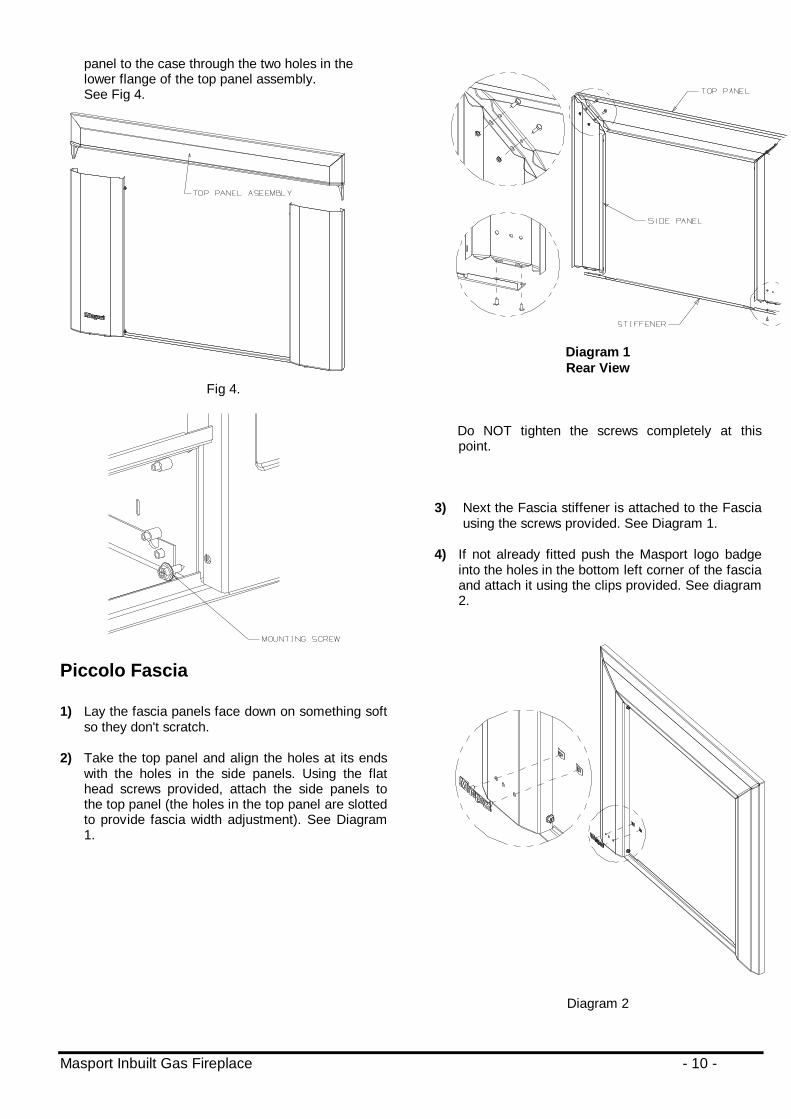
10) Lower the top panel assembly into place with thelocating prongs pointing down so that they fit insidethe top edges of each side panel. Fasten the top
Masport Inbuilt Gas Fireplace - 10 -
panel to the case through the two holes in thelower flange of the top panel assembly.See Fig 4.
Fig 4.
Piccolo Fascia
1) Lay the fascia panels face down on something softso they don't scratch.
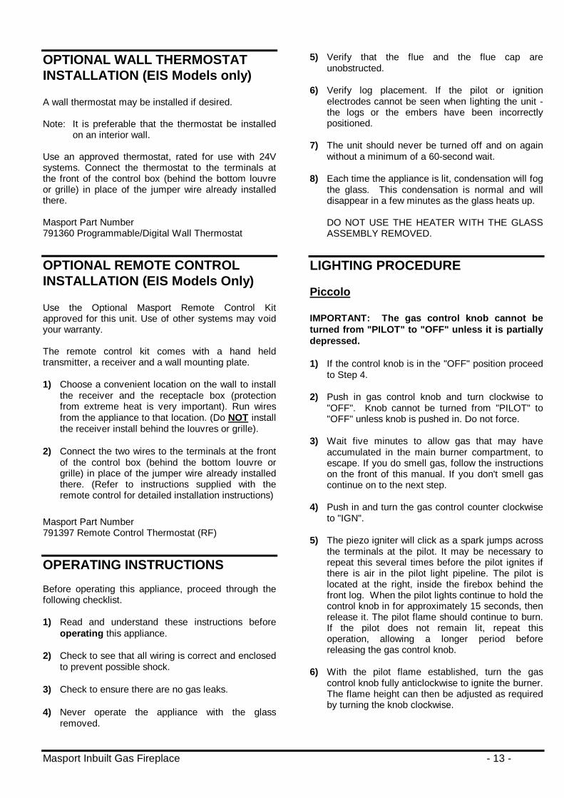
2) Take the top panel and align the holes at its endswith the holes in the side panels. Using the flathead screws provided, attach the side panels tothe top panel (the holes in the top panel are slottedto provide fascia width adjustment). See Diagram1.
Diagram 1Rear View
Do NOT tighten the screws completely at thispoint.
3) Next the Fascia stiffener is attached to the Fasciausing the screws provided. See Diagram 1.
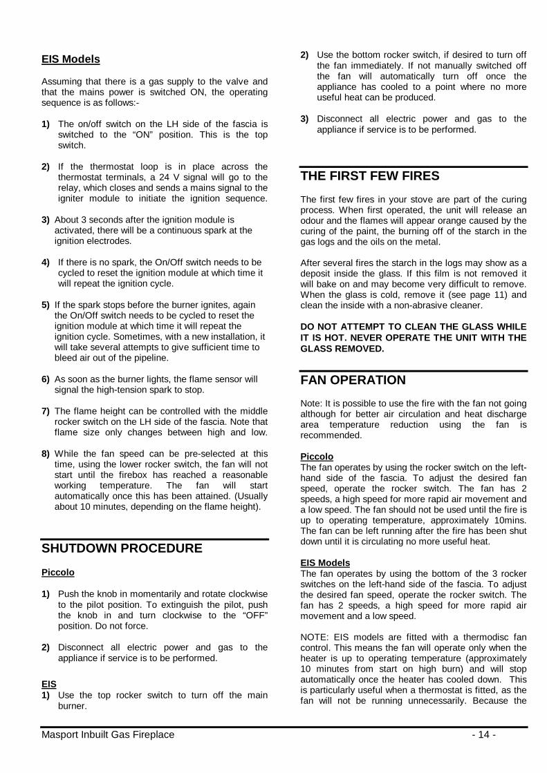
4) If not already fitted push the Masport logo badgeinto the holes in the bottom left corner of the fasciaand attach it using the clips provided. See diagram2.
Diagram 2

Masport Inbuilt Gas Fireplace - 11 -
5) Offer the fascia into position on the unit and adjustuntil it fits correctly. Remove the fascia carefullyand tighten all the screws
6) The power cord should be run behind the fasciapanel and out through the slot in the bottom of thefascia. The rubber grommet on the power cordshould be inserted into the slot to protect the mainslead against possible damage.
Note: There is no fan switch on the Piccolo as itis a single speed fan.
7) Attach the assembled fascia to the case using the4 remaining screws.
FLUSH FRONT GLASS REMOVAL
1) Remove the top louvre by lifting it upwards andoutwards to clear the retaining pins.
2) Remove the two trim fastening screws, one ateach end of the top trim as per the diagram belowand remove the top glass trim.
3) Remove the 2 black cover trims one at each sideof the glass by lifting them upwards and then out.Refer to diagram 2. Pull the top of the trimforward before the bottom.
4) This will now free the glass for removal from thefire and give access to the logs, burner etc.
Diagram 2
BAY FRONT REMOVAL
1) Remove the top grille by lifting it upwards andoutwards to clear the retaining pins.
2) Release the bottom grille retaining screw onequarter turn anticlockwise and remove the bottomgrille by lifting it upwards and outwards to clearthe retaining pins.
3) Remove the two window fastening screws, one ateither end of the window as per the diagram below.
4) This will now free the window for removal from thefire by swinging the top outwards slightly and liftingthe bottom edge clear of its retaining channel. Thiswill give access to the logs, burner etc.
INSERT SCREWDRIVERTO LIFT TRIM.
SIDE GLASS TRIM
TOP GLASS TRIM
TRIM FASTENINGSCREW.

Masport Inbuilt Gas Fireplace - 12 -
LOG & EMBER PLACEMENT
1) Once either the flush or bay windows are removedas per the above instructions the embers can beplaced in the fire.
2) Inspect the logs before ember installation. If thelogs are broken, do not use the fire until they arereplaced. Broken logs can interfere with the pilotoperation, combustion, etc.
3) LOG IDENTIFICATION790338 - Rear log, mounting centres - 340 mm990339 - Left Centre log, mtg. centres - 115 mm790356 - Left Front log, mtg. centres - 93 mm790341 - Right Lower log, mtg. centres - 122 mm790342 - Right Upper log, length - 245 mm790343 - Centre log, length - 255 mm
Fit the first four logs on their mounting posts onthe gas burner in the following order:-1. The Rear log2. The Left Centre log3. The Left Front log4. The Right Lower logPlace the right Upper log on top of the hollow in
the right Lower log as illustrated, maintaining the130 dimension shown to the rear of the firebox.Place the Top log, positioned as shown with its
butt end sitting against the raised front lip of theburner. Verify the correct distances to the right sideof the firebox.5.
4) Spread embers between and under the logs nofurther than 50 mm back from front lip of burnerand also on the floor of the firebox at each side ofthe burner. Do NOT block the ventilation slotsin the burner. Embers can be placed down thesides to hide the black steelwork etc.
5) Re-install the flush or bay window. Do not operatethe appliance with the window removed.
GAS PRESSURE TEST
The unit is preset to give the correct gas input at thespecified injector pressures shown on the label. Themaximum injector pressure is:
Gas Type Piccolo EISLow High Low High
Natural Gas 0.30kPa 0.75kPa 0.35kPa 0.82kPaPropane 0.90kPa 2.10kPa 1.00kPa 2.30kPa
The injector pressure is controlled by a regulator builtinto the gas valve on EIS models. The Piccolo has apressure regulator separate from the valve. In allcases, when adjusting the pressure, check it at theoutlet pressure test point on the valve. The pressurecheck should be carried out with the unit burning andthe correct pressures are shown above.
Piccolo
EIS Models
Masport Inbuilt Gas Fireplace - 13 -
OPTIONAL WALL THERMOSTATINSTALLATION (EIS Models only)
A wall thermostat may be installed if desired.
Note: It is preferable that the thermostat be installedon an interior wall.
Use an approved thermostat, rated for use with 24Vsystems. Connect the thermostat to the terminals atthe front of the control box (behind the bottom louvreor grille) in place of the jumper wire already installedthere.
Masport Part Number791360 Programmable/Digital Wall Thermostat
OPTIONAL REMOTE CONTROLINSTALLATION (EIS Models Only)
Use the Optional Masport Remote Control Kitapproved for this unit. Use of other systems may voidyour warranty.
The remote control kit comes with a hand heldtransmitter, a receiver and a wall mounting plate.
1) Choose a convenient location on the wall to installthe receiver and the receptacle box (protectionfrom extreme heat is very important). Run wiresfrom the appliance to that location. (Do NOT installthe receiver install behind the louvres or grille).
2) Connect the two wires to the terminals at the frontof the control box (behind the bottom louvre orgrille) in place of the jumper wire already installedthere. (Refer to instructions supplied with theremote control for detailed installation instructions)
Masport Part Number791397 Remote Control Thermostat (RF)
OPERATING INSTRUCTIONS
Before operating this appliance, proceed through thefollowing checklist.
1) Read and understand these instructions beforeoperating this appliance.
2) Check to see that all wiring is correct and enclosedto prevent possible shock.
3) Check to ensure there are no gas leaks.
4) Never operate the appliance with the glassremoved.
5) Verify that the flue and the flue cap areunobstructed.
6) Verify log placement. If the pilot or ignitionelectrodes cannot be seen when lighting the unit -the logs or the embers have been incorrectlypositioned.
7) The unit should never be turned off and on againwithout a minimum of a 60-second wait.
8) Each time the appliance is lit, condensation will fogthe glass. This condensation is normal and willdisappear in a few minutes as the glass heats up.
DO NOT USE THE HEATER WITH THE GLASSASSEMBLY REMOVED.
LIGHTING PROCEDURE
Piccolo
IMPORTANT: The gas control knob cannot beturned from "PILOT" to "OFF" unless it is partiallydepressed.
1) If the control knob is in the "OFF" position proceedto Step 4.
2) Push in gas control knob and turn clockwise to"OFF". Knob cannot be turned from "PILOT" to"OFF" unless knob is pushed in. Do not force.
3) Wait five minutes to allow gas that may haveaccumulated in the main burner compartment, toescape. If you do smell gas, follow the instructionson the front of this manual. If you don't smell gascontinue on to the next step.
4) Push in and turn the gas control counter clockwiseto "IGN".
5) The piezo igniter will click as a spark jumps acrossthe terminals at the pilot. It may be necessary torepeat this several times before the pilot ignites ifthere is air in the pilot light pipeline. The pilot islocated at the right, inside the firebox behind thefront log. When the pilot lights continue to hold thecontrol knob in for approximately 15 seconds, thenrelease it. The pilot flame should continue to burn.If the pilot does not remain lit, repeat thisoperation, allowing a longer period beforereleasing the gas control knob.
6) With the pilot flame established, turn the gascontrol knob fully anticlockwise to ignite the burner.The flame height can then be adjusted as requiredby turning the knob clockwise.
Masport Inbuilt Gas Fireplace - 14 -
EIS Models
Assuming that there is a gas supply to the valve andthat the mains power is switched ON, the operatingsequence is as follows:-
1) The on/off switch on the LH side of the fascia isswitched to the “ON” position. This is the topswitch.
2) If the thermostat loop is in place across thethermostat terminals, a 24 V signal will go to therelay, which closes and sends a mains signal to theigniter module to initiate the ignition sequence.
3) About 3 seconds after the ignition module isactivated, there will be a continuous spark at theignition electrodes.
4) If there is no spark, the On/Off switch needs to becycled to reset the ignition module at which time itwill repeat the ignition cycle.
5) If the spark stops before the burner ignites, againthe On/Off switch needs to be cycled to reset theignition module at which time it will repeat theignition cycle. Sometimes, with a new installation, itwill take several attempts to give sufficient time tobleed air out of the pipeline.
6) As soon as the burner lights, the flame sensor willsignal the high-tension spark to stop.
7) The flame height can be controlled with the middlerocker switch on the LH side of the fascia. Note thatflame size only changes between high and low.
8) While the fan speed can be pre-selected at thistime, using the lower rocker switch, the fan will notstart until the firebox has reached a reasonableworking temperature. The fan will startautomatically once this has been attained. (Usuallyabout 10 minutes, depending on the flame height).
SHUTDOWN PROCEDURE
Piccolo
1) Push the knob in momentarily and rotate clockwiseto the pilot position. To extinguish the pilot, pushthe knob in and turn clockwise to the “OFF”position. Do not force.
2) Disconnect all electric power and gas to theappliance if service is to be performed.
EIS1) Use the top rocker switch to turn off the main
burner.
2) Use the bottom rocker switch, if desired to turn offthe fan immediately. If not manually switched offthe fan will automatically turn off once theappliance has cooled to a point where no moreuseful heat can be produced.
3) Disconnect all electric power and gas to theappliance if service is to be performed.
THE FIRST FEW FIRES
The first few fires in your stove are part of the curingprocess. When first operated, the unit will release anodour and the flames will appear orange caused by thecuring of the paint, the burning off of the starch in thegas logs and the oils on the metal.
After several fires the starch in the logs may show as adeposit inside the glass. If this film is not removed itwill bake on and may become very difficult to remove.When the glass is cold, remove it (see page 11) andclean the inside with a non-abrasive cleaner.
DO NOT ATTEMPT TO CLEAN THE GLASS WHILEIT IS HOT. NEVER OPERATE THE UNIT WITH THEGLASS REMOVED.
FAN OPERATION
Note: It is possible to use the fire with the fan not goingalthough for better air circulation and heat dischargearea temperature reduction using the fan isrecommended.
PiccoloThe fan operates by using the rocker switch on the left-hand side of the fascia. To adjust the desired fanspeed, operate the rocker switch. The fan has 2speeds, a high speed for more rapid air movement anda low speed. The fan should not be used until the fire isup to operating temperature, approximately 10mins.The fan can be left running after the fire has been shutdown until it is circulating no more useful heat.
EIS ModelsThe fan operates by using the bottom of the 3 rockerswitches on the left-hand side of the fascia. To adjustthe desired fan speed, operate the rocker switch. Thefan has 2 speeds, a high speed for more rapid airmovement and a low speed.
NOTE: EIS models are fitted with a thermodisc fancontrol. This means the fan will operate only when theheater is up to operating temperature (approximately10 minutes from start on high burn) and will stopautomatically once the heater has cooled down. Thisis particularly useful when a thermostat is fitted, as thefan will not be running unnecessarily. Because the

Masport Inbuilt Gas Fireplace - 15 -
thermodisc is fitted, it is not necessary to operate theswitch on the fascia. It can be kept permanently on atthe desired speed setting. The fascia switch overridesthe thermodisc if it is set in the central “off” position.
NORMAL OPERATING SOUNDS OFGAS APPLIANCES
It is possible that you will hear some sounds from yourgas appliance. This is perfectly normal due to the factthat there are various gauges and types of steel usedwithin your appliance. Listed below are someexamples,all are normal operating sounds and these shouldnot be considered as defects in your appliance.
Fan:Masport gas appliances use high tech blowers to pushheated air further into the room. It is not unusual forthe fan to make a "whirring" sound when ON. Thissound will increase or decrease in volume dependingon the speed setting of your fan.
Burner Tray:The burner tray is positioned directly under the burnerand logs and is made of a different gauge materialfrom the rest of the firebox and body. Therefore, thevarying thicknesses of steel will expand and contract atslightly different rates, which can cause "ticking" and"cracking" sounds. You should also be aware that asthere are temperature changes within the unit thesesounds would likely re-occur, again, this is normal forsteel fireboxes.
Pilot Flame (Piccolo Only):While the pilot flame is on it can make a very slight"whisper" sound.
Gas Control Valve:As the gas control valve turns ON and OFF, a dullclicking sound may be audible, this is normal operationof a gas regulator or valve.
Unit Body/Firebox:Different types and thicknesses of steel will expandand contract at different rates resulting in some"cracking" and "ticking" sounds being heard throughoutthe cycling process.
GENERAL MAINTENANCEINSTRUCTIONS
1) Keep the burner and control compartment clean bybrushing and vacuuming at least once a year.Always turn the gas valve to OFF before cleaning.When cleaning the logs, use a clean softpaintbrush, as the logs are fragile and easilydamaged.
2) Clean the appliance, glass and louvres with adamp cloth only when it is cold. Never use anabrasive cleaner. The gold louvres will bescratched if abrasives are used to clean them.The heater is finished in a heat resistant paint andshould only be refinished with heat resistant paint(not with wall paint).
3) Keep the area near the appliance clear and freefrom combustible materials, petrol and otherflammable vapours and liquids.
WARNING: CHILDREN AND ADULTS SHOULDBE ALERTED TO THE HAZARDS OF HIGHSURFACE TEMPERATURE AND SHOULDSTAY AWAY TO AVOID BURNS OR CLOTHINGIGNITION. YOUNG CHILDREN SHOULD BECAREFULLY SUPERVISED WHEN THEY AREIN THE SAME ROOM AS THE APPLIANCE.
CAUTION: ANY SAFETY SCREEN OR GUARDREMOVED FOR SERVICING AN APPLIANCEMUST BE REPLACED PRIOR TO OPERATINGTHE APPLIANCE. (Australia only)
CLOTHING OR OTHER FLAMMABLEMATERIAL SHOULD NOT BE PLACED ON ORNEAR THE APPLIANCE.
4) Periodically check the pilot flames (Piccolo only),there should be three strong flames (approx. 19mm long) - 1 flame to the rear burner, 1 to theignition electrode and 1 to the thermocouple.
If you have an incorrect flame pattern, contact yourMasport dealer.
SERVICING INSTRUCTIONS(Routine maintenance schedule)Servicing must be carried out only by authorisedpersonnel.
Your Masport heater must be checked yearly by anauthorised Technician. This periodic maintenanceshould cover the following points:-
1) Keep the burner and control compartment and anyair entry points clean by brushing and vacuuming.Always turn the gas valve to OFF before cleaning.When cleaning the logs, use a clean softpaintbrush, as the logs are fragile and easilydamaged.
2) Make a periodic check of burner for proper logposition and condition. Visually check the flamepattern of the burner periodically, making sure theflames are steady, not lifting or floating.
3) The appliance and flue system must be inspectedbefore use and thereafter annually to ensure thatthe flow of combustion and ventilation air is not

Masport Inbuilt Gas Fireplace - 16 -
obstructed. During the annual service call, theburner should be removed from the burner trayand cleaned. Replace the embers but do not blockthe air slots.
4) Clean the fan of any lint or foreign matter.
5) After the above steps, check the pilot flames(Piccolo only), there should be three strong flamesapprox. 19 mm long - 1 flame to the rear burner, 1to the ignition electrode and 1 to the thermocouple.
6) Check the operation of the thermostat (if fitted) byturning its control point above and below ambientroom temperature and checking the response ofthe fire.
Other points to be checked after completing theabove:-Thermocouple generationGas consumption rateCarbon dioxide content in the combustion productsFlue operation.
Log Replacement
The unit should never be used with broken logs. Turnoff the gas valve and allow the unit to cool beforeremoving the glass to carefully remove the logs. Thepilot light generates enough heat to burn someone. Iffor any reason a log should need replacement, youmust use the proper replacement log. The position ofthese logs must be as shown in the diagram on page12.
Note: Improper positioning of logs may createcarbon build-up and will alter the unit’sperformance. Malfunctioning due to improper logplacement is not covered under warranty.
Glass Gasket
If the glass gasket requires replacement use 25mm flatglass gasket for the Flush Front, Masport part number786774 or 10mm flat glass tape for the curved windowMasport part number 790229.
Gold-Plated Trim
The 24-carat gold plated finish on the trim requireslittle maintenance, needing only be cleaned with adamp cloth. DO NOT use abrasive materials orchemical cleaners, as they will harm the finish andvoid the warranty. Clean any fingerprints off beforeturning the unit on. If the top louvres start todiscolour, check the glass gasket seal and replaceif necessary.
Glass Replacement
Your Masport stove is supplied with high temperature,5 mm Neoceram ceramic glass that will withstand thehighest heat that your unit will produce. In the eventthat you break your glass by impact, purchase yourreplacement from an authorised Masport dealer only,and follow our step-by-step instructions forreplacement.
Bay Glass Removal
1) Remove the window from the unit (refer to removalinstructions on page 10) and place on a softsurface to prevent scratching.
2) Remove the nuts holding the glass retainers inplace.
3) Remove the glass retainers.
4) Replace the glass.
5) Reverse the previous steps, replace the retainersand fasten with the nuts but do not over tighten, asthis can break the glass.
6) Refit the window to the fire and check the seal.
Flush Glass Replacement
Remove the glass by following the instructions on page11. Fit the new glass, replacing the gaskets ifnecessary.
Fan Maintenance
If your fan requires maintenance or replacement,access to the fan is through the plate on the rear wallof the firebox.
Note: The unit MUST NOT be operated withoutthe fan access panel securely in place.
To remove fan:
1) Turn the unit and/or pilot off and allow it to cool toroom temperature.
2) Unplug or disconnect the power source to the fire.
3) Remove glass front (see page 11).
4) Remove logs and embers (see page 12).
5) Remove the burner (2 screws at the front, refer todiagram over page).
6) Loosen the screws securing the rear fan accesspanel in place. Lift and withdraw the panel passingthe keyhole slots over the screw heads.
7) Remove the fan-shipping nuts.

Masport Inbuilt Gas Fireplace - 17 -
8) Unplug the fan lead from the plug on the controlbox (EIS models). On Piccolo models the mainslead will need withdrawing with the fan or unplugthe individual wires.
9) On EIS models remove the screws holding thethermodisc bracket or disconnect the two push onconnectors at the thermodisc.
10) On Piccolo models, disconnect the wires at theearthing post on the rear wall just above the fanmotor.
11) Lift and withdraw the fan assembly from itsmounting pins on the base of the fire. The fan willcome out through the access panel.
12) Reassemble in the reverse order.
NG to LP Conversion (EIS Models):
This conversion must be carried out by a qualifiedTechnician. If in doubt do not attempt thisconversion!
1) Turn the unit off.
2) Unplug or disconnect the power source to the fire.
3) Remove the glass front (see page 11).
4) Remove the logs (see page 12).
5) Remove the 2 screws holding the burner assemblyto the burner tray as below. Push the burner to theleft and lift out.
6) Access is now available to the brass main injector.A 13mm spanner will be required to remove theinjector, the elbow behind the injector will alsoneed to be held to avoid twisting the pipe work.Remove the main injector and discard.
7) Reinstall the new LP injector marked “1.7” andtighten. Again avoid twisting the pipe work.
8) Reinstall the burner. Ensure that the aerationshutter on the burner is fully open.
9) Reverse steps 4), 3) & 2).
10) Check for gas leaks.
11) Reset high and low pressures refer to page 12.
12) Check operation at high and low settings.
CLEANING INSTRUCTIONS
The outside of the fascia and glass should need nomore than an occasional wipe with a damp cloth toremove any dust which may have settled.
All gas appliances incorporating a live fuel effect anddesigned to operate with luminous flames may exhibitcarbon deposition, particularly if the combustion airentry slots under the heater are obstructed or theaeration air inlets are clogged with lint. Any otherlifting, floating or lighting back should be checked by arecognised Masport gas fire Technician.
After a period of time the inside of the glass mayrequire cleaning. To do this, carefully remove the glass(See Glass Removal and Assembly, page 11), andclean the inside surface with a non-abrasive cloth anda non-scratching type household cleaning liquid.
Replace the parts as detailed on page 11, keepingfingerprints off the inside glass surfaces.No other user maintenance should be necessary. If yourequire any other service or adjustments, contact yourTechnician or Dealer.
DETAIL B
BURNER FASTENING SCREW
Masport Inbuilt Gas Fireplace - 18 -
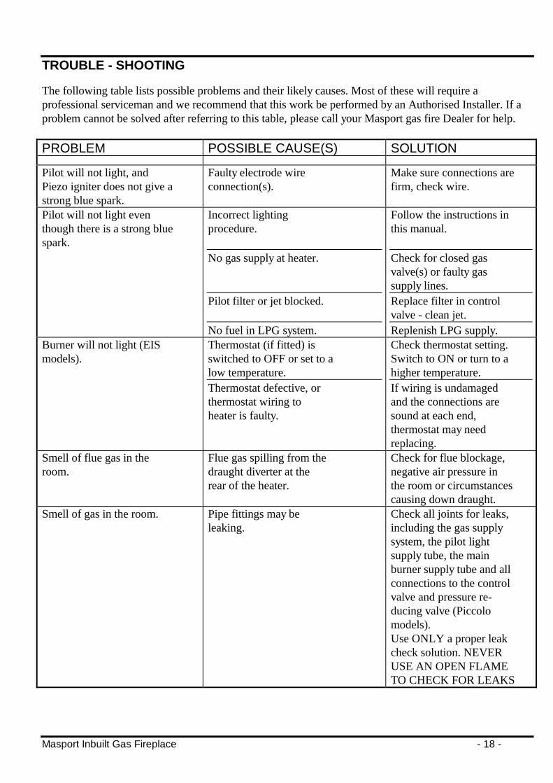
TROUBLE - SHOOTING
The following table lists possible problems and their likely causes. Most of these will require aprofessional serviceman and we recommend that this work be performed by an Authorised Installer. If aproblem cannot be solved after referring to this table, please call your Masport gas fire Dealer for help.
PROBLEM POSSIBLE CAUSE(S) SOLUTION
Pilot will not light, andPiezo igniter does not give astrong blue spark.
Faulty electrode wireconnection(s).
Make sure connections arefirm, check wire.
Pilot will not light eventhough there is a strong bluespark.
Incorrect lightingprocedure.
No gas supply at heater.
Pilot filter or jet blocked.
No fuel in LPG system.
Follow the instructions inthis manual.
Check for closed gasvalve(s) or faulty gassupply lines.Replace filter in controlvalve - clean jet.Replenish LPG supply.
Burner will not light (EISmodels).
Thermostat (if fitted) isswitched to OFF or set to alow temperature.Thermostat defective, orthermostat wiring toheater is faulty.
Check thermostat setting.Switch to ON or turn to ahigher temperature.If wiring is undamagedand the connections aresound at each end,thermostat may needreplacing.
Smell of flue gas in theroom.
Flue gas spilling from thedraught diverter at therear of the heater.
Check for flue blockage,negative air pressure inthe room or circumstancescausing down draught.
Smell of gas in the room. Pipe fittings may beleaking.
Check all joints for leaks,including the gas supplysystem, the pilot lightsupply tube, the mainburner supply tube and allconnections to the controlvalve and pressure re-ducing valve (Piccolomodels).Use ONLY a proper leakcheck solution. NEVERUSE AN OPEN FLAMETO CHECK FOR LEAKS

Masport Inbuilt Gas Fireplace - 19 -
PROBLEM POSSIBLE CAUSE(S) SOLUTION
A thin coating of black sootforms inside the glass.
Combustion air supplyrestricted.
Over-supply of gas.
Logs or embers out of position.
Clean all primary andsecondary airpassageways.Adjust gas delivery pressureat test point.Arrange logs/emberscorrectly.
A white coating formsinside the glass.
Residues in new logs being burnedoff.
Follow glass cleaningdirections under CleaningInstructions.
Fan hums but there is poorair circulation.
Dirty fan impeller Disconnect electrical power.Remove and clean fanimpeller.
No power to fan. Make sure fan plug is firmlyhome and that fan switch isnot in the OFF position.Check that the power socketworks with another appliance.
Fan will not run.
Thermodisc not activated (EISmodels)
Wait until heater achievesworking temperature.
Ignition spark continues after thefire has lit. (EIS models only)
Phase and Neutral connectionsreversed in the house power supply.
Get a qualified person tocorrect the house wiring.

Masport Inbuilt Gas Fireplace - 20 -
ANNUAL SERVICE RECORD
DATE SERVICE DETAILS SERVICED BY
INSTALLED BY: ____________________________
DATE: ____________________________
Masport Gasfires are manufactured in New Zealand byMASPORT LTD. 1/37 MT WELLINGTON HIGHWAY.
P.O. Box 14-349 Panmure, Auckland New Zealand.A.G.A. Approvals:
Piccolo, Sofia & Madrid - All Certificate No 6361.