mar 19890005: maybelle river - alberta...
TRANSCRIPT

MAR 19890005: MAYBELLE RIVER Received date: Sep 30, 1989 Public release date: Oct 01, 1990 DISCLAIMER By accessing and using the Alberta Energy website to download or otherwise obtain a scanned mineral assessment report, you (“User”) agree to be bound by the following terms and conditions: a) Each scanned mineral assessment report that is downloaded or otherwise obtained from Alberta
Energy is provided “AS IS”, with no warranties or representations of any kind whatsoever from Her Majesty the Queen in Right of Alberta, as represented by the Minister of Energy (“Minister”), expressed or implied, including, but not limited to, no warranties or other representations from the Minister, regarding the content, accuracy, reliability, use or results from the use of or the integrity, completeness, quality or legibility of each such scanned mineral assessment report;
b) To the fullest extent permitted by applicable laws, the Minister hereby expressly disclaims, and is released from, liability and responsibility for all warranties and conditions, expressed or implied, in relation to each scanned mineral assessment report shown or displayed on the Alberta Energy website including but not limited to warranties as to the satisfactory quality of or the fitness of the scanned mineral assessment report for a particular purpose and warranties as to the non-infringement or other non-violation of the proprietary rights held by any third party in respect of the scanned mineral assessment report;
c) To the fullest extent permitted by applicable law, the Minister, and the Minister’s employees and agents, exclude and disclaim liability to the User for losses and damages of whatsoever nature and howsoever arising including, without limitation, any direct, indirect, special, consequential, punitive or incidental damages, loss of use, loss of data, loss caused by a virus, loss of income or profit, claims of third parties, even if Alberta Energy have been advised of the possibility of such damages or losses, arising out of or in connection with the use of the Alberta Energy website, including the accessing or downloading of the scanned mineral assessment report and the use for any purpose of the scanned mineral assessment report so downloaded or retrieved.
d) User agrees to indemnify and hold harmless the Minister, and the Minister’s employees and agents against and from any and all third party claims, losses, liabilities, demands, actions or proceedings related to the downloading, distribution, transmissions, storage, redistribution, reproduction or exploitation of each scanned mineral assessment report obtained by the User from Alberta Energy.
Alberta Mineral Assessment Reporting System
IeDoO5
.
LOGISTICAL REPORT ON TIME-DOMAIN EM SURVEYS IN THE MAYBELLE RIVER AREA OF NORTHERN ALBERTA
On Behalf Of:
Uranerz Exploration and Mining Limited 1300 Saskatoon Square 410 - 22nd Street East Saskatoon, Saskatchewan S7K 5T6
Contact: P. Robertshaw Telephone: (306)665-0566
0
.
By:
JVX Ltd. 60 West Wilmot St., Unit 22 Richmond Hill, Ontario L4B 1M6
Contact: Blame Webster Telephone:(416) 731-0972
JVX Ref: 89031 UEM Ref: 71-42 March 1989
JVx .
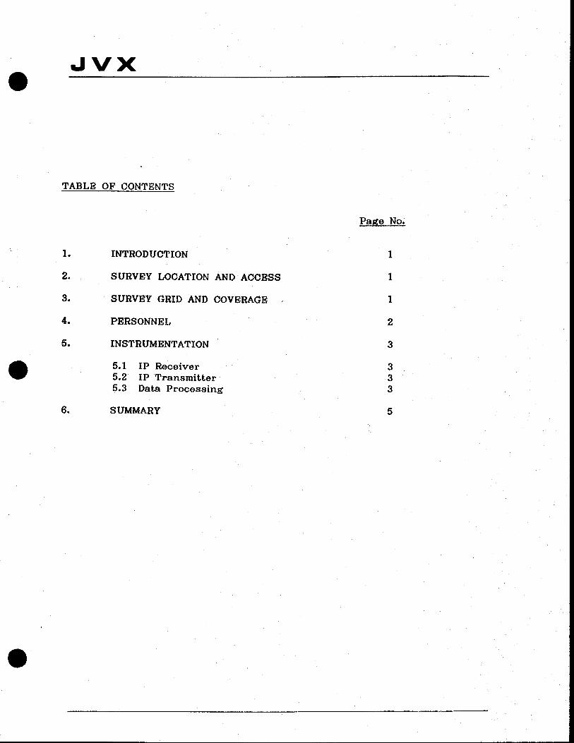
I TABLE OF CONTENTS
1. INTRODUCTION
2. SURVEY LOCATION AND ACCESS
3. SURVEY GRID AND COVERAGE
4. PERSONNEL
5. INSTRUMENTATION
. 5.1 IP Receiver 5.2 IP Transmitter 5.3 Data Processing
6. SUMMARY
Page No.
1
1
1
2
3
3 3 3
5
I
0
• Jvx O
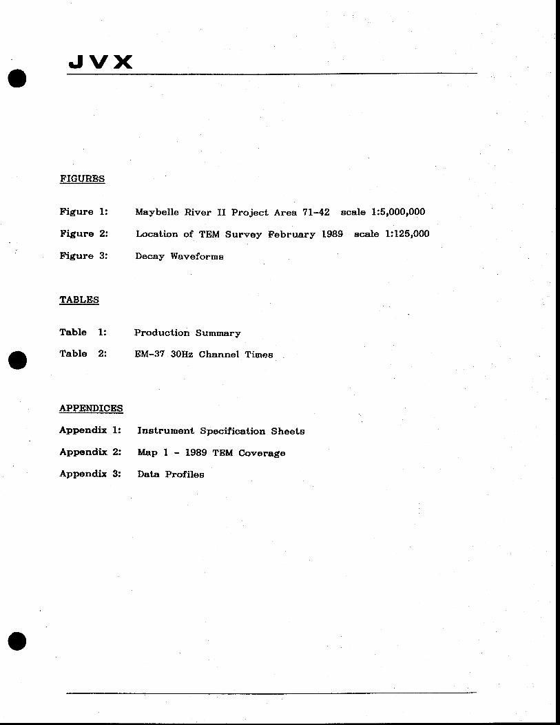
FIGURES
Figure 1: Maybelle River II Project Area 71-42 scale 1:5,000,000
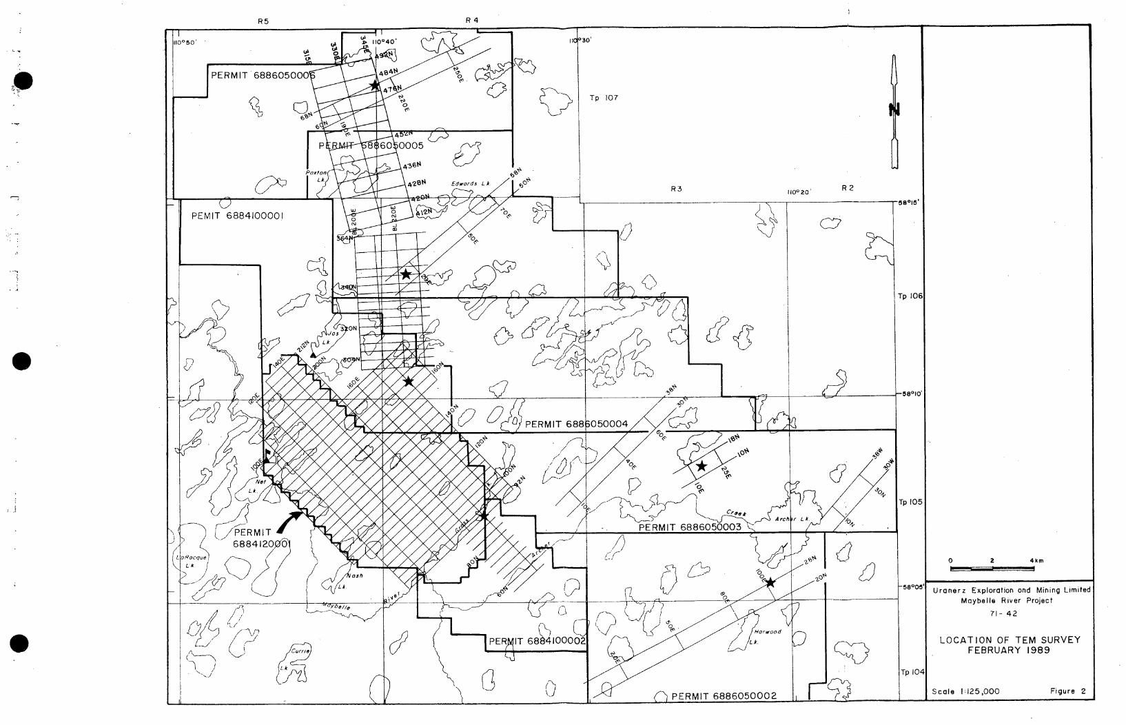
Figure 2: Location of TEM Survey February 1989 scale 1:125,000
Figure 3: Decay Waveforms
TABLES
Table 1: Production Summary
Table 2 EM-37 30Hz Channel Times
APPENDICES
Appendix 1: Instrument Specification Sheets
Appendix 2: Map I - 1989 TEM Coverage
Appendix 3: Data Profiles
.
I
.
Jvx
A REPORT ON GROUND GEOPHYSICAL SURVEYS CONDUCTED IN THE MAYBELTJE RIVER AREA
OF NORTHERN ALBERTA
On Behalf Of
Uranerz Exploration and Mining Limited.
1. INTRODUCTION
From January 29th and February 23rd, 1988, Time Domain Electromagnetic (TDEM) surveys were conducted on behalf of Uranerz Exploration and Mining Limited (henceforth called UEM) on the Maybelle River Project 71-42 in northern Alberta, by JVX Ltd.
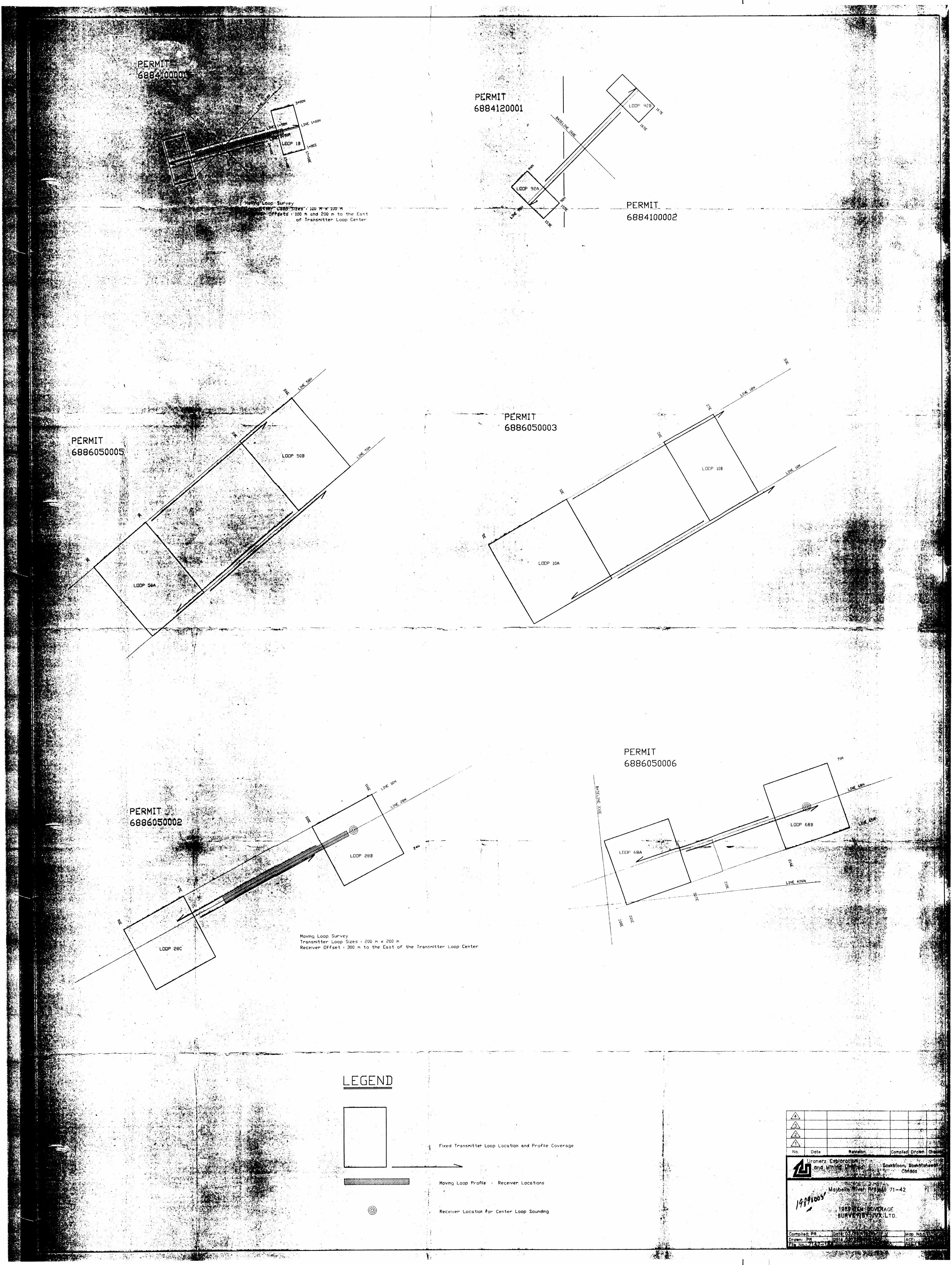
The survey employed fixed loops of 600m x 600m and 800m x 800m and moving loops of lOOm x lOOm, and 200m x 200m with a nominal station separation of 50 metres.
• 2. SURVEY LOCATION AND ACCESS
The survey area is located in the May-belle River area of northern Alberta approximately 100km southeast of Fort Chipewyan.
Figure 1 shows the location of the survey area with respect to nearby population centres at a scale of 1:5,000,000.
3. SURVEY GRID AND COVERAGE
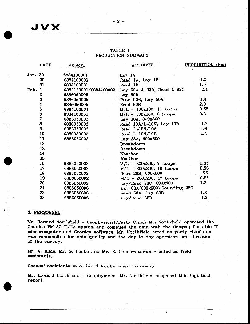
Survey locations are illustrated in figure 2 at scale of 1:125,000. Map 1 of appendix II illustrates the TDEM coverage at a scale of 1:10,000. A total of aproximately 18.65 line-km of fixed loop coverage and aproximately 2.55 line-km of moving loop coverage was achieved. Daily activity, applicable permit areas and daily- production are detailed in table I below.
0
-2-
Jvx .
TABLE 1 PRODUCTION SUMMARY
.
DATE
Jan. 29 30 31
Feb. 1 2 3 4 5 6 7 8 9 10 11 12 13 14 15 16 17 18 19 20 21 22 23
PERMIT ACTIVITY PRODUCTION (km)
6884100001 Lay 1A 6884100001 Read 1A, Lay lB
1.0
6884100001 Read lB
1.0 6884120001/6884100002 Lay 92A & 92B, Read L-92N
2.4
6886050005 Lay SOB 6886050005 Read 50B, Lay 50A
1.4
6886050005 Read SOB
2.8 6884100001 M/L - lOOxlOO, 11 Loops
0.55
6884100001 M/L - lOOxlOO, 6 Loops
0.3 6886050003 Lay 1A, 800x800 6886050003 Read bAIL-10N, Lay lOB
1.7
6886050003 Read L.-18N/10A
1.6 6886050003 Read L-10N/10B
1.4
6886050002 Lay 28A, 600x600 Breakdown Breakdown Weather Weather
6886050002 M/L - 200x200, 7 Loops
035 6886050002 M/L - 200x200, 10 Loops
0.50
6886050002 Read 28B, 600x600
1.55 6886050002 M/L - 200x200, 17 Loops
0.85
6886050002 Lay/Read 280, 600x600
1.2 6886050006 Lay 68A (600x600) ,Sounding 28C 6886050006 Read 68A, Lay 68B
1.3
6886050006 Lay/Read 68B
1.3
4 PERSONNEL
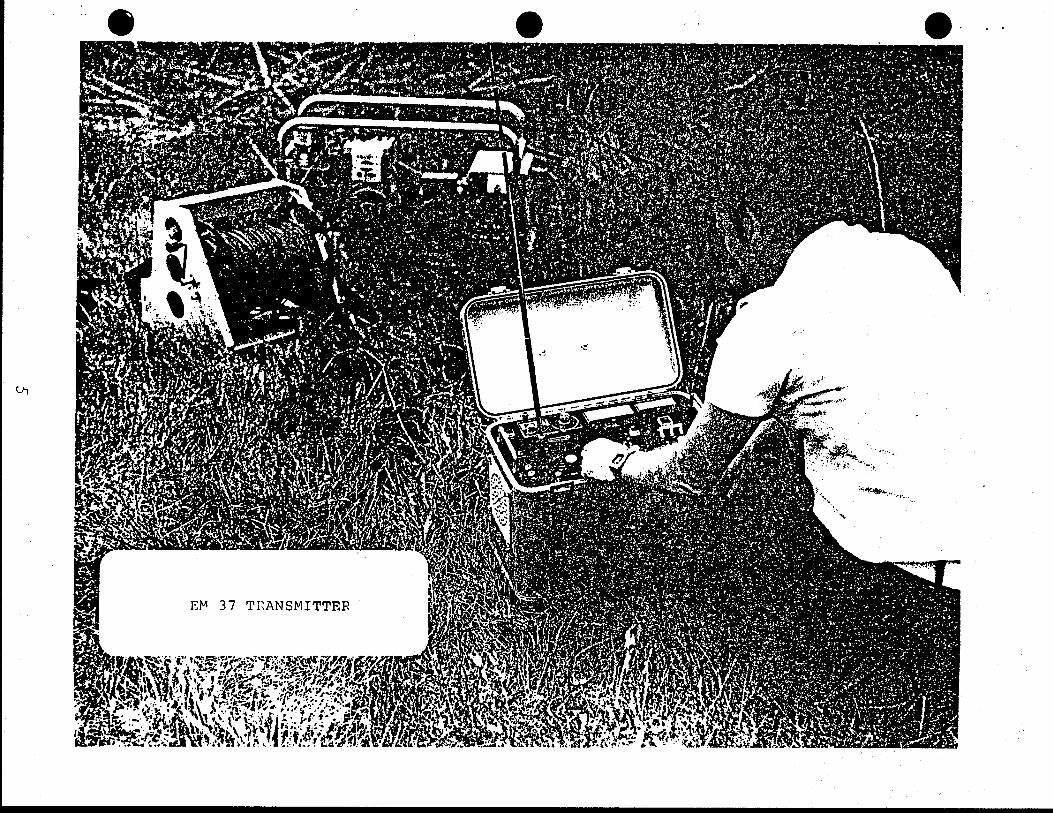
Mr. Howard Northfield - Geophysicist/Party Chief. Mr. Northfield operated the Geonics EM-37 ThEM system and compiled the data with the Compaq Portable II microcomputer and Geonics software. Mr. Northfield acted as party chief and was responsible for data quality and the day to day operation and direction of the survey.
Mr. A. Blais, Mr. G. Locke and Mr. E. Ocheewaawan - acted as field assistants.
Casusal assistants were hired locally when necessary
Mr. Howard Northfield - Geophysicist. Mr. Northfield prepared this logistical report.
0
-3-.
Jvx
Mr. Phil Robertshaw - Senior Geophysicist, UEM Ltd. Mr. Robertahaw provided overall supervision of the survey and reporting from the Jas Lake camp.
Mr. Blame Webster — President, JVX Ltd. Mr. Webster provided overall supervision of the survey and reporting from the Toronto office.
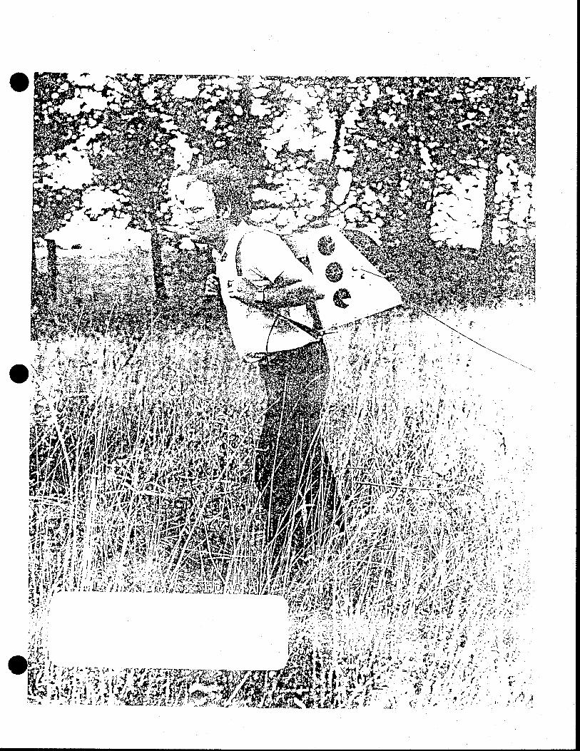
5. INSTRUMENTATION
5.1 Receiver See Appendix I
5.2 Transmitter See Appendix I
5.3 Data Processing
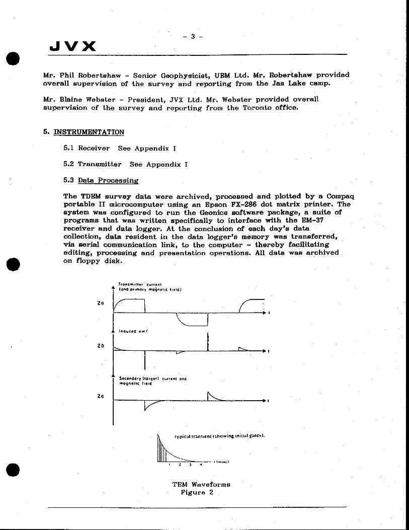
The TDEM survey data were archived, processed and plotted by a Compaq portable II microcomputer using an Epson FX-286 dot matrix printer. The system was configured to run the Geonics software package, a suite of programs that was written specifically to in with the EM-37 receiver and data logger. At the conclusion of each day's data collection, data resident in the data logger's memory was transferred, via serial communication link, to the computer — thereby facilitating editing, processing and presentation operations. All data was archived on floppy disk.
T:ot.tm,iuq,
(and pf.mOIy mOQAhIC 1,614)
Ifld.Ctd Ornt
SICoAdGry (Osq,SI Cur,SAI and
''OQflStIC field
typiCI tranicfl( (showing init i al gate.).
.
.
is
Zo
2b
2c
TEM Waveforms Figure 2

.
Jvx -4-
.
For a 30 Hz transmit and receive time the slices of integration for the Geonics EM-37 system are as follows:
FROM TO MIDPOINT Channel msec msec meec
1 0.080 0.097 0.089
2 0.097 0.121 0.109
3 0.121 0.158 0.140
4 0.158 0.195 0.177
5 0.195 0.224 0.219
6 0.224 0.316 0.280
7 0.316 0.393 0.355
8 0.393 0.492 0.634
9 0.492 0.634 0.563
10 0.634 0.790 0.712
11 0.790 0.962 0.876
12 0.962 1.221 1.090
13 1.221 1.580 1.400
14 1.580 1.950 1.765
15 1.950 2.440 2.195
16 2.440 3.160 2.800
17 3.160 3.930 3.545
18 3.930 4.920 4.425
19 4.920 6.340 5.630
20 6.340 7.900 7.120
Table 2 EM-37 30Hz Channel Times
0
I
Jvx -5-
6. SUMMARY:
From January 29th to February 23rd, 1989, JVX Limited carried out TEM surveys on behalf of UEM on the Maybelle River Project 71-42 in northern Alberta.
The survey employed fixed loop and moving loop tecniques using a 50 metre sampling interval. A total of approximately 18.65 line-km of fixed 100p
and approximately 2.55 line-km of moving loop coverage was achieved.
The digital data from this survey has been archived by JVX. One copy of the data on diskette was given to UEM at the conclusion of the survey.
The copy of all the data will be held by JVX on UEM'B behalf fo a period not 1085 than five years. UEM may at any time within this period ask for copies of the raw data or derivative products.
If there are any questions with regard to the survey please do not hesitate to call the undersigned at JVX Ltd.
. Respectfully submitted,
JVX Led. I
Howard J. Northfield, B.Sc.
.
Blame Webster, B.Sc. PresidentS
0
I .
Appendix I
Specification Sheets
0
C EON I Cs LIMITED T:4 580
1745 Meyerside Dr. Unit 8 Mississauga, Ontario Canada L5T 105 Cables: Geonics
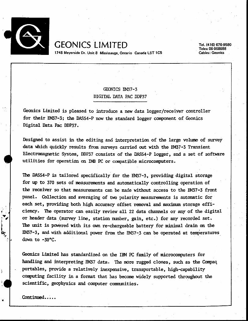
GEONICS F!'437-3
DIGITAL DATA PAC DDP37
Geonics Limited is pleased to introduce a new data logger/receiver controller for their EM37-3; the DAS54-P now the standard logger component of Geonics Digital Data Pac DDP37.
Designed to assist in the editing and interpretation of the large volume of survey
data which quickly results from surveys carried out with the Thf37-3 Transient Electromagnetic System, DDP37 consists of the DAS54-P logger, and a set of software
utilities for operation on ]}IB PC or compatible microcomputers.
The DAS54-P is tailored specifically for the F1v137-3, providing digital storage
for up to 370 sets of measurements and automatically controlling operation of
the receiver so that measurements can be made without access to the Ev137-3 front
panel. Collection and averaging of two polarity measurements is automatic for each set, providing both high accuracy offset removal and maximum storage effi-ciency. The operator can easily review all 22 data channels or any of the digital
or header data (survey line, station number, gain, etc.) for any recorded set. The unit is powered with its own re-chargeable battery for minimal drain on the
EM37-3, and with additional power from the EM37-3 can be operated at temperatures down to -30°C.
Geonics Limited has standardized on the I4 PC family of microcomputers for
handling and interpreting Ev137 data. The more rugged clones, such as the Compaq
portables, provide a relatively inexpensive, transportable, high-capability
computing facility in a format that has become widely supported throughout the scientific, geophysics and computer communities.
Continued.....
.
-2-
Users of the FM37-3 Digital Data Pac are supplied with a suite of software
facilities for acquisition, editing, and interpretation of P1437 survey data.
Program P0L37 provides the interface to the DAS54-P, transferring recorded data from the logger to the computer or loading programs into the logger using
the standard RS232C protocal. Once in the computer, data can be readily edited
and displayed using program DAT37, and different reduction procedures carried
out to generate. profiles or decay plots as raw field data, turnoff corrected
impulse response, integrated step response, or late stage apparent resistivity
or conductivity. Outputs are available for line printer and HP 7470 plotter.
Interpretation is aided by several forward modelling facilities specially
written for rectangular transmitter geometries. MJD37 allows the operator
to model and combine the instrunnt responses for geological structures including:
Ci) Uniform halfspace;
(ii) Infinite horizontal thin conductive sheet at depth;
(iii) Finite rectangular thin conductive plates.
Program RECrAN models the response for arbitrary horizontal conductivity layering.
By comparing actual field data with the results of forward modelling, the inter-
preter can quickly identify likely candidates for the sub-surface structure.
Also available as an additional option is TEMIX, a program for the automatic
inversion of P1437 soundings to a horizontally layered model.
Geonics Limited is continuing to develop additional techniques for the inter-
pretation of P1437 survey data, and as new programs are developed they will be available to users of the P1437-3.
MAY 1987
.
.
—I
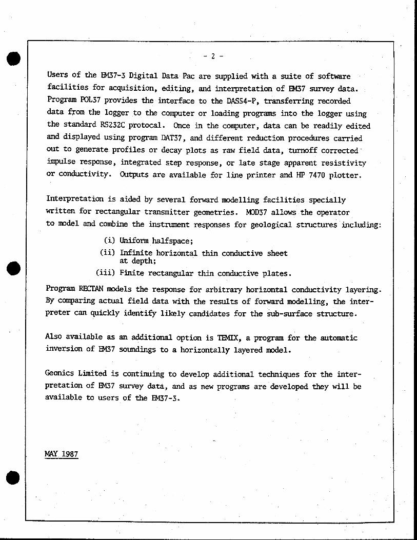
Page 2.
2. INPUT AND OUTPUT CONNECTIONS
.
Input Data Via - Keyboards and 50 pin "D't subminiature connector - Cannon P/N DD50P
Pin assignments for the connector are as follows:
PIN DESCRIPTION PIN DESCRIPTION
1 Ch 5 Ch 2 Ch 6 Cho 3 Ch 7 Ch 4 Ch 8 Ch 9 Ch 30 N/C
10 Ch 10 31 Ready
11 Ch 11 32 + 12V Power (Battery)
12 Ch 12 33 N/C
13 Ch 13 34 Digital Ground
14 Ch 14 35 N/C
15 N/C 36 Freq (LSB)
16 + 12V Regulated 37 N/C
17 - 12V Regulated 38 Ch 15
18 Ch 18 39 Ch 16
19 Ch 19 40 Ch 17
20 Ch 20 41 Gain 0 (LSB)
21 Ch 0 (Primary Field) 42 Gain 1
22 T/O Time 43 Gain 2
23 Freq (MSB) 44 Gain 3 (MSB)
24 N/C 45 N/C
25 N/C 46 Signal Ground (analog)
26 N/C 47 Heater Ground
27 N/C 48 Polarity Input
28 N/C 49 Start Integration
29 N/C 50 Polarity Output
.
...3
-j

DAS54-P TECHNICAL SPECIFICATIONS
1. GENERAL CHARACTERISTICS
Number of Analog Channels
Number of Records
Analog Inputs
Recording Resolution
Analog Input Impedance
Display
Keyboard
Number of Digital I/O
Output Communication
Output Baud Rate
Programming Language
Internal Power Back-up Battery Main Battery
External Power Requirements (from EM37-3) Normal Mode Display
Temperature Range
Dimensions
Weight
22
370 (4 digit recording) 260 (5 digit recording)
± S Volts Max.
0.1 mV
100 kc2
2 Line by lb character alphanumeric LCD.
Hermetically sealed membrane keyboard with 21 keys.
:9
Serial RS-232C
300 to 19200 BPS
Polycode
Alkaline 9-V / 40 hours 6 Size 'tAA't - Rechargeable
± 10 mA at ± 12 volts 600 mA at 12 volts (only when it turns on
-30°C to 50°C
22 x 11.5 x 6.5 cm
1.8 kg
I.
O
.
I I
Page 3.
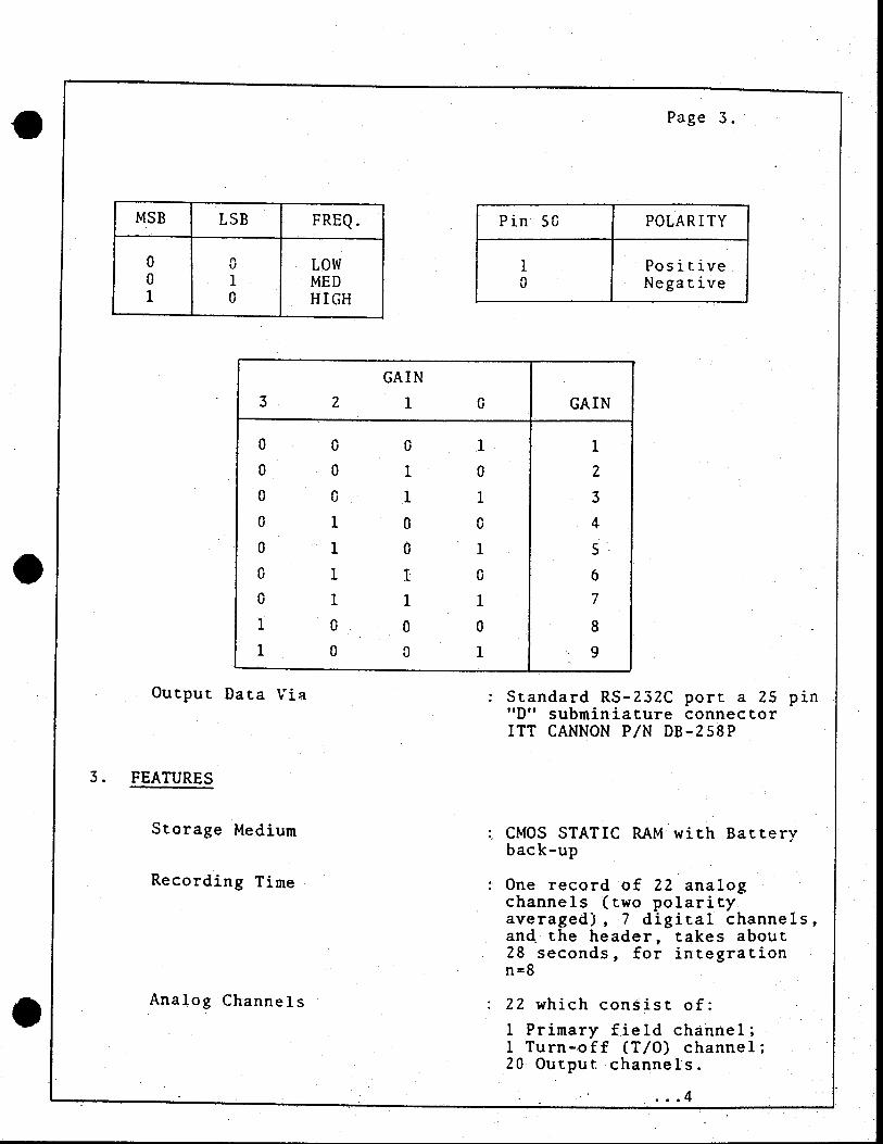
MSB LSB FREQ.
o 0 LOW O 1 MED 1 0 HIGH
Pin 50 POLARITY
1 Positive 0 Negative
Output Data Via
3. FEATURES
Storage Medium
Recording Time
Standard RS-232C port a 25 pin "D" subminiature connector ITT CANNON P/N DB-258P
CMOS STATIC RAM with Battery back-up
One record of 22 analog channels (two polarity averaged), 7 digital channels, and the header, takes about 28 seconds, for integration n=8
22 which consist of:
1 Primary field channel; 1 Turn-off (T/O) channel; 20 Output channels.
0
Analog Channels
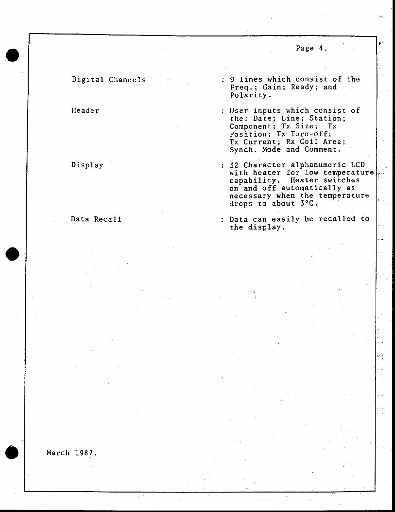
Display
Data Recall
Page 4.
9 lines which consist of the Freq.; Gain; Ready; and Polarity.
User inputs which consist of the: Date; Line; Station; Component; Tx Size; Tx Position; Tx Turn-off; Tx Current; Rx Coil Area; Synch. Mode and Comment.
32 Character alphanumeric LCD with heater for low temperature capability. Heater switches on and off automatically as necessary when the temperature drops to about 3°C..
Data can easily be recalled to the display.
w Digital Channels
Header
0
March 1987.
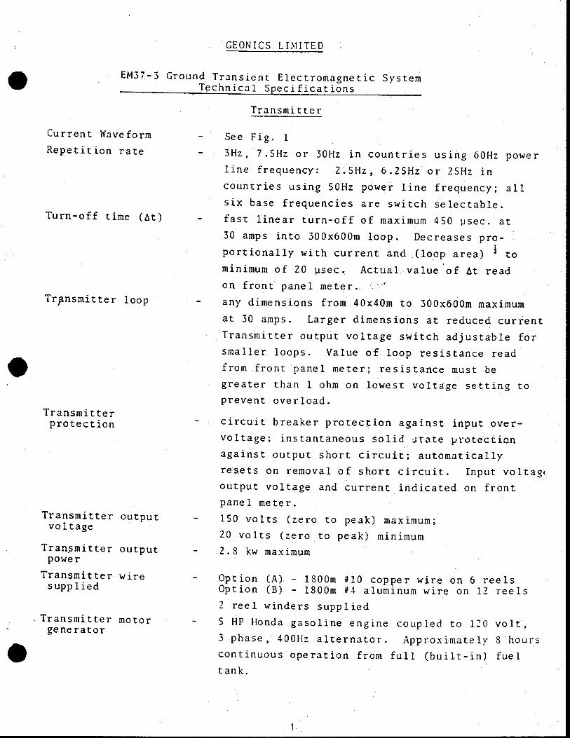
GEONICS LIMITED
.
EM37-3 Ground Transient Electromagnetic System Technical Specifications
Transmitter
.
.
See Fig. 1
3Hz, 75l-1z or 30Hz in countries using 60Hz power
line frequency; 2.5Hz, 6.25Hz or 25Hz in
countries using 50Hz power line frequency; all
six base frequencies are switch selectable.
fast linear turn-off of maximum 450 usec. at
30 amps into 300x600m loop. Decreases pro-
portionally with current and (loop area) to
minimum of 20 usec. Actual value of At read
on front panel meter.
any dimensions from 40x40m to 300x600m maximum
at 30 amps. Larger dimensions at reduced current
Transmitter output voltage switch adjustable for
smaller loops. Value of loop resistance read
from front panel meter; resistance must be
greater than 1 ohm on lowest voltage setting to
prevent overload.
- circuit breaker protection against input over-
voltage; instantaneous solid state protecticn
against output short circuit; automatically
resets on removal of short circuit. Input voltage
output voltage and current indicated on front
panel meter.
- 150 volts (zero to peak) maximum;
20 volts (zero to peak) minimum - 2.3 kw maximum
- Option (A) - 1300m ItlO copper wire on 6 reels Option (B) - 1800m #4 aluminum wire on 12 reels 2 reel winders supplied
- S HP Honda gasoline engine coupled to 120 volt,
3 phase, 400Hz alternator. Approximately S hours
continuous operation from full (built-in) fuel tank.
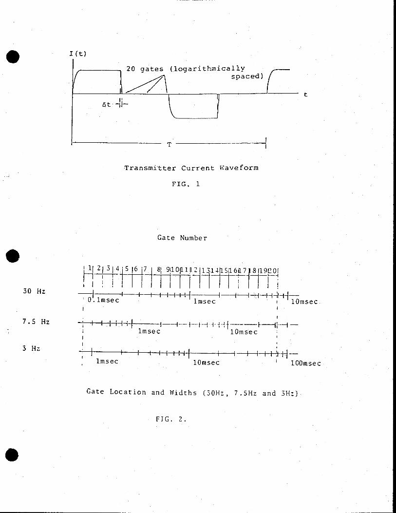
Current Waveform
Repetition rate
Turn-off time (At)
Trnsmjtter loop
Transmitter protection
Transmitter output voltage
Transmitter output power
Transmitter wire supplied
Transmitter motor generator
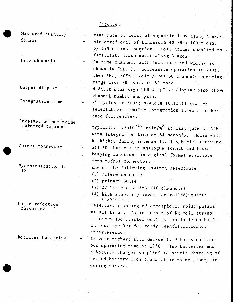
Output connector
Synchronization to Tx
Receiver
Receiver output noise referred to input
Receiver batteries
0
time rate of decay of magnetic flux along 3 axes
air-cored coil of bandwidth 40 kI(z; 100cm dia.
by 7x5cm cross-section. Coil holder supplied to
facilitate measurement along 3 axes.
20 time channels with locations and widths as
shown in Fig. 2. Successive operation at 30Hz,
then 3Hz, effectively gives 30 channels covering
range from 80 psec. to 80 msec.
4 digit plus sign LED display; display also show
channel number and gain.
cycles at 30Hz; n=4,6,8,10,12,14 (switch
selectable); similar integration times at other
base frequencies.
typically l.5x10 0 volt/M 2 at last gate at 30Hz
with integration time of 34 seconds. Noise will
be higher during intense local spherics activity.
all 20 channels in analogue format and house-
keeping functions in digital format available
from output connector.
any of the following (switch selectable)
(1) reference cable
(2) primary pulse
(3) 27 tlHz radio link (40 channels)
(4) high stability (oven controlled) quart: crystals.
Selective clipping of atmospheric noise pulses
at all times. Audio output of Rx coil (trans-
mitter pulse blanked out) is available on built-
in loud speaker for ready identificationof
interference.
12 volt rechargeable Gel-cell; 9 hours continu-
ous operating time at 17°C. Two batteries and
a battery charger supplied to permit charging of
second battery from transmitter motor-generator
during survey.
.
Measured quantity
Sensor
Time channels
Output display
Integration time
Noise rejection circuitry
.
I (t)
20 gates (logarithmically so aced)
—T— t
T
Transmitter Current waveform
FIG. 1
30 Hz
7.5 Hz
3 Hz
Gate Number
I if 2j 3 f 4 S 167 8 9 ; 1 012I1i4saoa7 8119e0
H fJt I IThTTfl • 0.lmsec imsec i lOmsec
I tHHH-J imsec lOmsec
imsec lOmsec lOOmsec
Gate Location and Widths (30H7-, 7.5Hz and 3Hz)
FIG. 2.
0
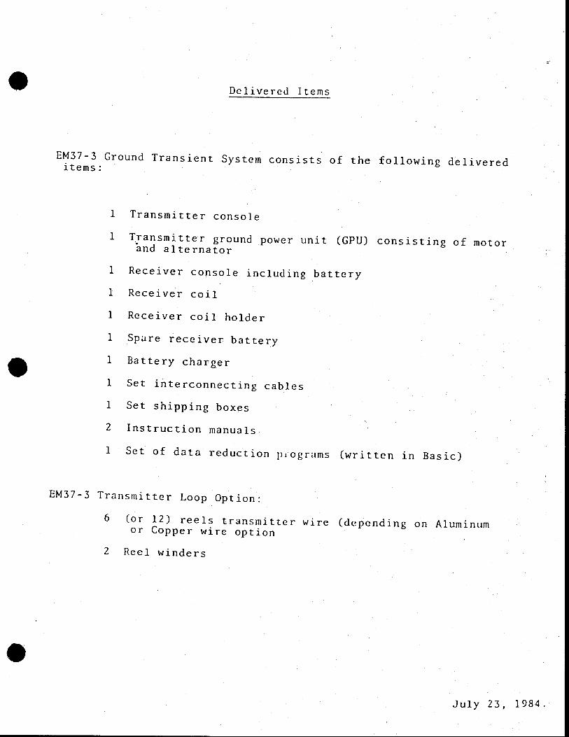
Delivered Items
S
EM37-3 Ground Transient System consists of the following delivered items:
1 Transmitter console
1 Transmitter ground power unit (GPIJ) consisting of motor and alternator
1 Receiver console including battery
1 Receiver coil
1 Receiver coil holder
1 Spare receiver battery
1 Battery charger
1 Set interconnecting cables
1 Set shipping boxes
2 Instruction manuals
1 Set of data reduction piograms (written in Basic)
I
EM37-3 Transmitter Loop Option:
6 (or 12) reels transmitter wire (depending on Aluminum or Copper wire option
2 Reel winders
July 3l984.
S
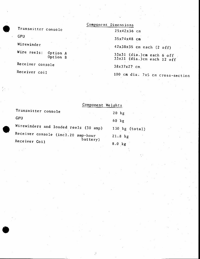
Transmitter console
GPU
Wirewjnde r
Wire reels: Option A Option B
Receiver console
Receiver coil
Component Dimensions
25x42x36 cm
35x74x48 cm
42x33x35 cm each (2 off)
33x3l (dia.)cm each 6 off 33x31 (dia.)cm each 12 off
38x37x27 cm
100 cm dia. 7x5 cm cross-section
Copnent Weights
Transmitter console 20 kg GPU
60 kg
S Wirewjnders and loaded reels (30 amp) 130 kg (total)
Receiver console (incl.20 amp-hour 21.8 kg Receiver Coil
battery) 8.0 kg
I
0
• • •
•
77' i• 4.;e cr .: 1 IL -J ' I
Ap
5 I \ ---
•
s
IL
•v__
-
. . . .,
O
I
od
..
r.
It
sf
'*1
—
:
c4J Aft
.... •.. cj H. ( : t j'
,._ 1t ct•;•
:? :ii.'/ ! (
• r.f ' I.. .. .
r I
.% .-• 1 ,.s ..
I 1
a'
i;. Wr? ' j . .' I. •;t.,?. ..
lop •4P.
• .
4W
-
•: ': . 5 (
.1
Ii ' •,. I .
t 1 W Iir : A
}
/ 4fr -fl 1Jf '/ P1
I.
I 1.4 r
-- :
k:' •
Ir -
.. -'.l
S . ••.
.' I .. p fl• t••,
. ,(ç•.j.:
-tr •(
t.• . t.' S r . fr lLF
I .
Appendix 2
Map 1 1989 TEM Coverage
.
I

0
.
.
(.4
.
0

0
.
Appendix 3
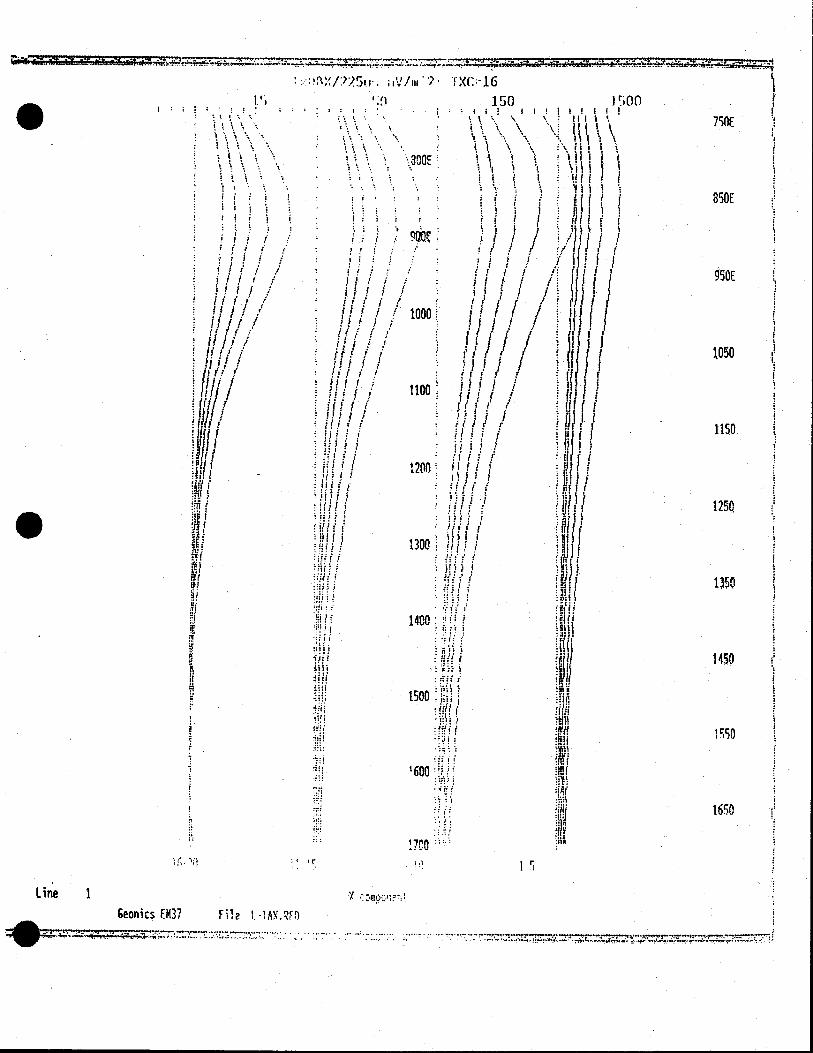
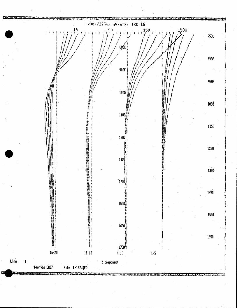
Data Profiles
.
.
.. . .. .....
• 7 1X(16
I ' 150 I: .
If
11 ( T 300E III
i I
t I'
I 41
I I I I I I I I I I/f
•1 QQ0
' .r' )
I : a Ill / It t
/
1000
1II
/•;/' 1 1100: 11/1 /
j1•i / 1 ft 1 i•
/ •i? I/f
HI I I f !I f ft 1 at nil
$'tflA II ii HI I
1111 I I II1
II' f ihi/ ' 1 IUIf
1300
al l 1: ? a I
1: 1400
H; I(II
tsoo :
1600
:II
1500 k 750E 'a.
I 350E
1 50E
1050
1150
12SQ
"so
1 450
1550
1650
17C0 S
Line 1 y Geonics U137 Eu?
. .•.
riV/m7; rXC-16
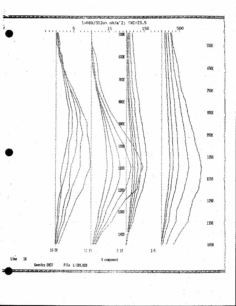
1xDBX/312u nV/n(2; TXC23.5
5 15 150 500 11111 11 I !IIII III I 11111 It
J 500E '
it
tn
tf
I 600E fl
t f : \
t31 I
550E
650E
700E
800E
750E
850E
\
1 I \ \ \ I I I I \ itM ii
1/ 'i \ 1I ••I
\100 i' I
I! ii i i
. I
I I r
II l• I I IIil.
Iff / ft/f / lli'(f
Iii 1 /11 /13001 1W f( H
ft
tI/ / 1400 i Jif f ifU
!iIIU 1 16-20 1115 510 1-5
Line 16 X component Geonics EM37 File L-18X.RED
- 950E
1050
1150
/
1 1250
1350
1450
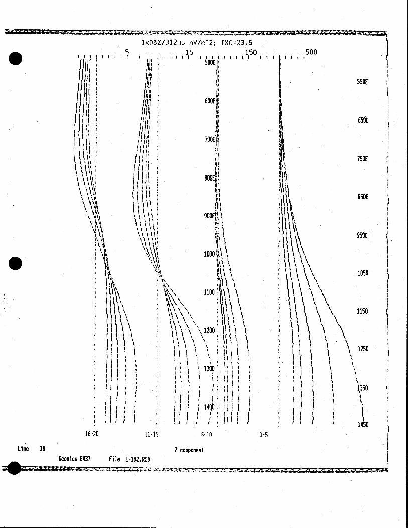
1xD8Z/312u; nV/m2; TXC23.5 5 15 150 500
IIIII il fi!cI;l III
I !J I 500E
If I II ' fll1
IJij( 600E
Ti U
111ff f ff 1 1 H if
I I (If Ni
ii 800E
it I ( S
\\\
\ ' I 1,
550E
650E
750E
850E
950E
fit 1000
1100
I
\1200. f't 1 : I
j I I
I
1300
I if I I
I! I
I I I Ii,' f If I I
16-20 li-is 6-10
Line lB Z component - Geonics E$37 File L-18Z.RED
1-5
1050
1150
1250
.
1xD8X/721.is nV/rn?; TXC16
1.5 1 50 150 Ill I 'liii 1,1 I IIlI II!
iE I'
I / ) 3
I It OOE] I
if r ? I
10 V
1 1
I l;i
•I
• ill ! if!
I I 1
• t A. \ ' '
\
\NWr \ \ \ \
%\,• \ \\
"\\ )
f !l
if
i (i! liii II1J
(i
' d) kilt
16-20 ti .15 6-10
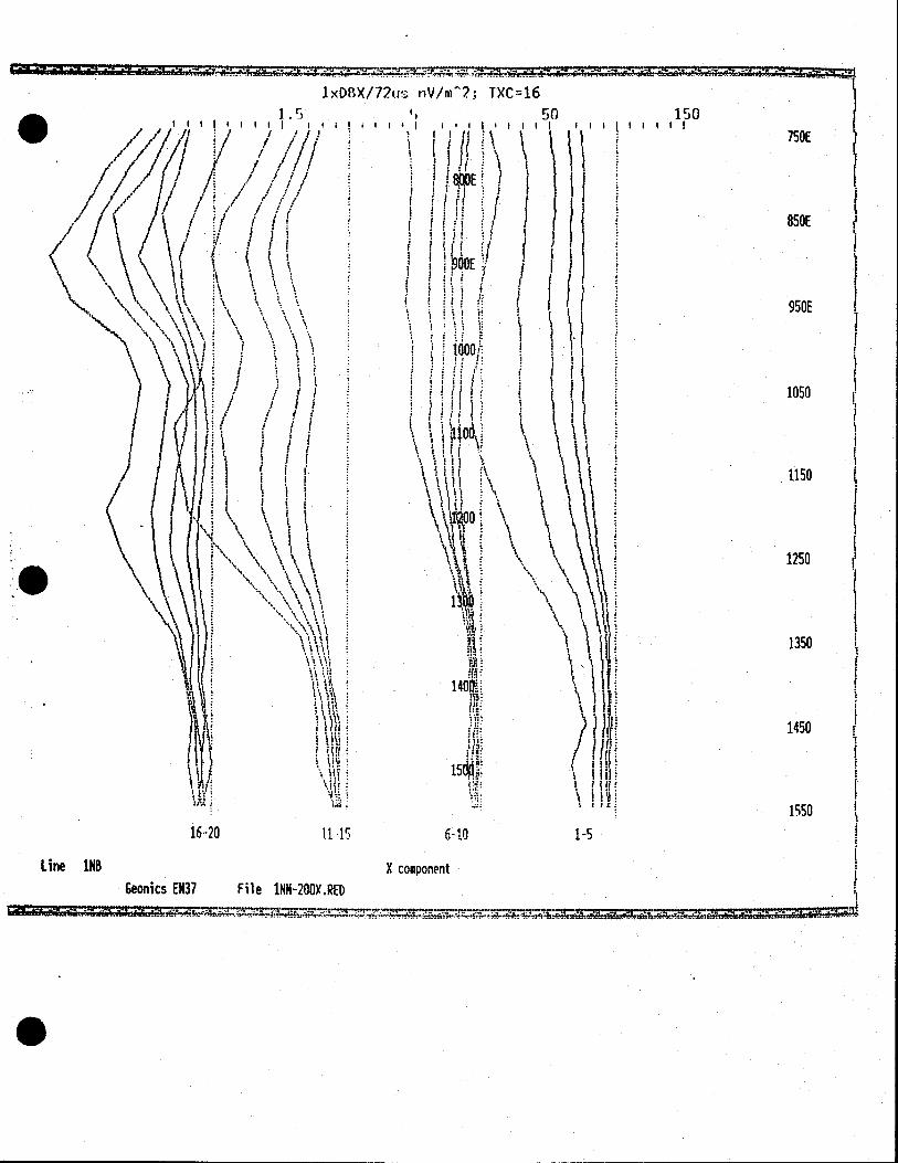
Line 1NR X component Geonics EM37 File INK-200X.RED
750E
850E
950E
1050
1150
1250
\ \
1p
1350
1450
J lj 1550
1-5
0
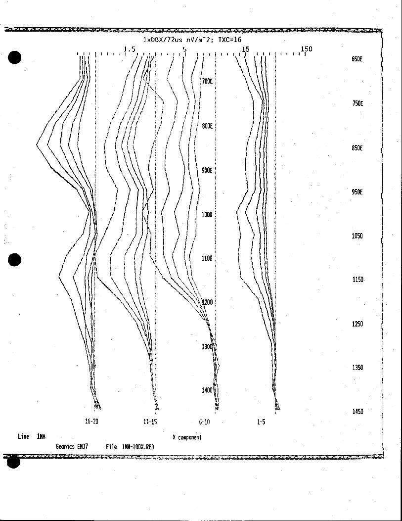
16-20 1115 6-10
Line 1NA X component Geonics EK37 File 1NN-100X.RED
1-5
IxDBX/72us riV/m - 2.z TXC16
J.5 1
1050
1150
1250
1350
1450
850E
950E
650E
750E
150 II I I I
.
I. x 7 2 1 Is 11V/i112 TXC16
1.5 5 50 I si
I / I IN j )
OF I M A-
\ t
\ '\
/
•1
(1 f[\(\ (( \ \\oo
it
If
I I• i!i
\ \ \(
1
li ti I I
(
ii i I III
I \\\V
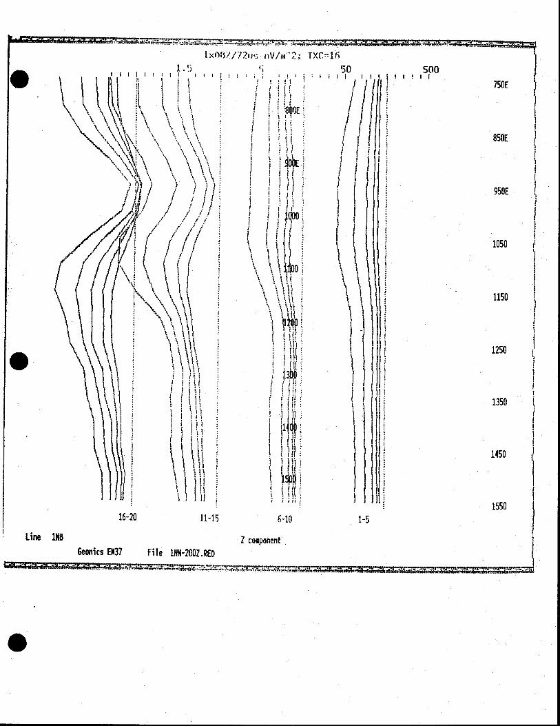
500 II!I II
750E
850E
950E
1050
1150
1250
1350
1450
1550 lb-Lu 11-15 6-10 1-5
Line 1NB Z component Geonics EM37 File 1N11-200Z.RED
is
J.xDB?/72u nV/rn2; TXC16
1.5 it .) 50
I III!, II III II !I iiti Ii! II
.
( I I ,, I /
I J I I 1800E
POOE
I I H ( ç \ i
I f N 'I
ø\ jj I
I
\ \ \ \ 1
500
WE
750E
850E
950E
- 1050
l F
II 1150
! f : I &
MU '. IHII \ ' I I (I
1 I I I I
I : t14 I F I F
SIll
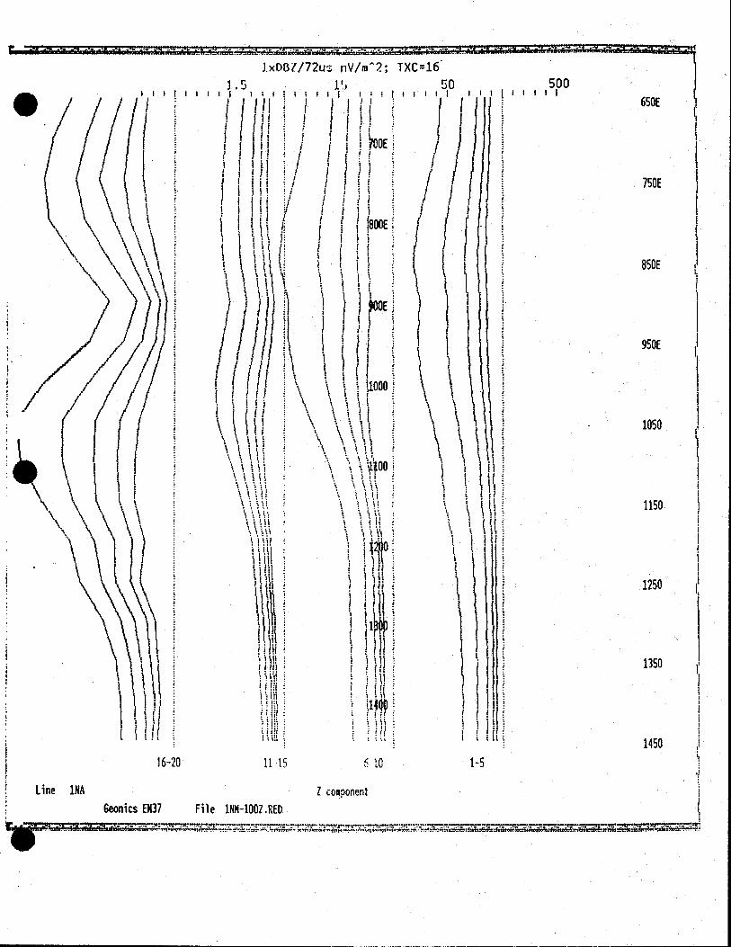
16-20 is 10
Line 1NA Z component
Geonics EH37 File 1NM-100Z.RED
1250
1350 ) 11 I J . Ii Ii
1450
1-5
.
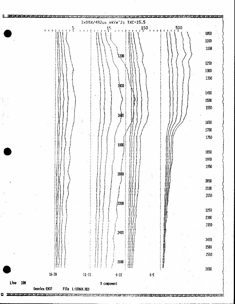
1xDfX/482u nV/n(2; TXC15.5
5 15 150 1;1111fil 1 111.1, I*t ; II
ItI I I II
( 1 11 I 1 \ I h\
\
I .iI! ii I
2OO
It
I I
i(1 \ Ii
t f I •i
It, I Itt
I I I
1800i Ii
S I
iII I I I I ( I
Iit ( I
Ii' I 2000
I :1.
I I : cJI If I I I 1
i2200.J
ii I i 1 1 t
I1t I 1
I I I
I ! LUu
1111 1
II I ii I f I I 0i
HH
I I11
fj ( I •1 1
LO(JU tAn. .11
Ill! 1 111':
Ill/I II I
S tit t
16-20 11-15 6-10
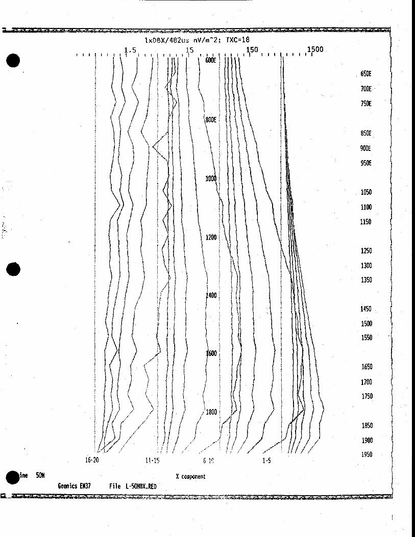
Line ION X component Geonics EN37 File 1-1ONAX.RED
1-5
500
II III
1 \
1050
1100
1150
1250
1300
1350
1450
1500
1550
1650
1700
1750
1850
1900
I 1950
2050
2100 -
2150
2250
2300
2350
2450
2500
2550
2650
rd a
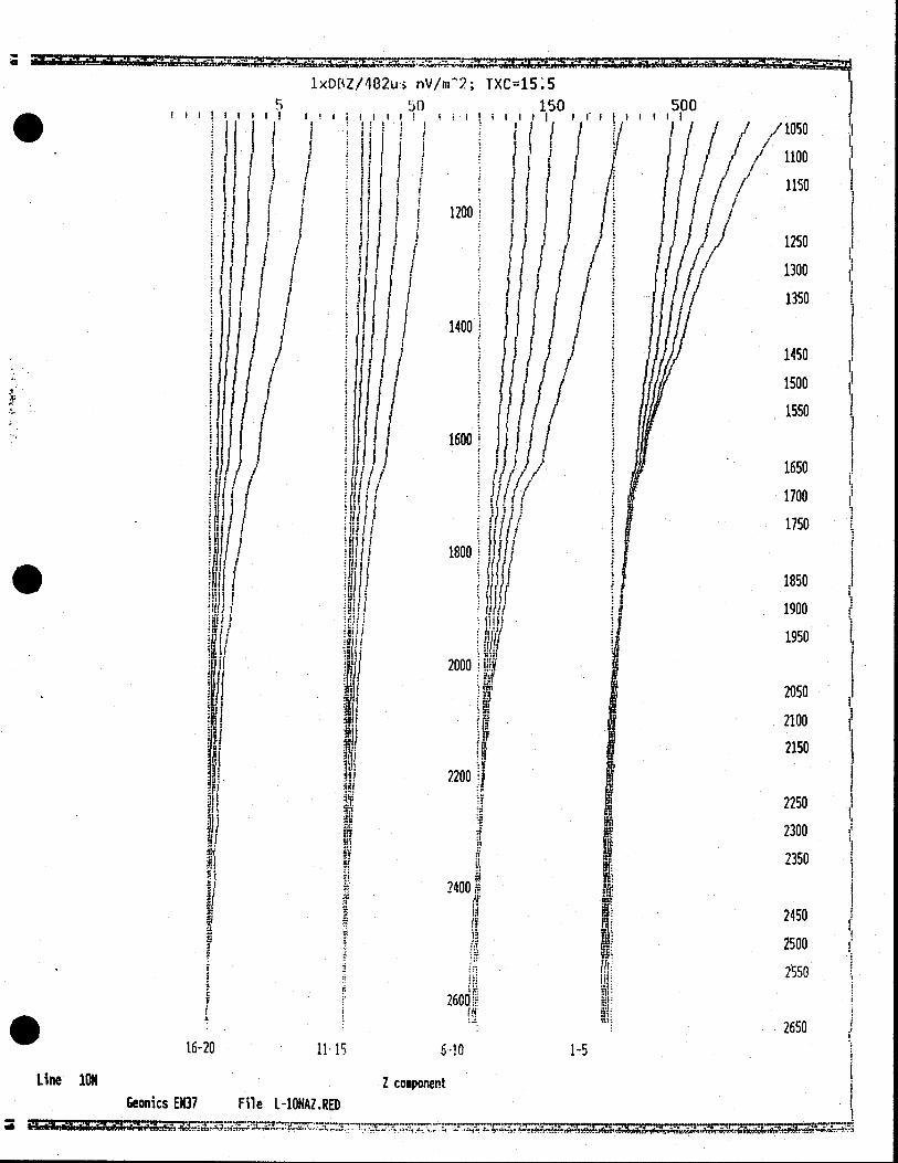
1xD1Z/482u nV/rn2; TXC15.5
5 50 150 500
ill! i ii! III 11111 II
;
I 1 I I I I 1 1:
I t I
:hI j 1200: H
It
/I
I
1400
I11 )11 / 11/1/
1600
1800
2000
.
/ 1050 '1
1100
1150
1250
1300
1350
1450
1500
1550
1650
1700
1750
1850
1900
1950
2050
2100
2150
2250
2300
2350
2450
2500
2550
2650
2200 We
VI
2400
I 2600k
16-20 111 60
Line 10$ Z component Geonics 007 File 1-10NAZ.RED
1-5
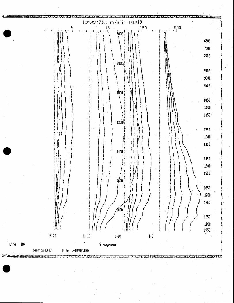
- 1xD3X/472u' nV/rn2; TXC19
5 Ir 150 500 1,1111111
\ k00 U \\
ll\ i!( I HI \ \ I
8004 1 1
\ \ \
I I
• ill ( I 0(
J I
)/ 1
ii
1/100
) I J I I / 800: r
3 / /
uiiI I/i ,1
16-20 11-1 6- 10
1-5
Line ION X component
Geonics EM37 File 1-1ONBX.RED
650E
700E 'I
750E
850E
900E
950E
1050
1100
1150
1250
1300
1350
1450
1500
1550
1650 ) 1750
1850
1900 1950
•

1-5
lODE
750E
850E
900E
950E
1050
.1100
1150
1250
1300
1350
1450
1500
1550
1650
1700
1750
1850
1900
1950
S. 1:<DBZ/472u nV/m2; TXC19
5 50 150 1500 III lull I iii l; ill III 11111
600E IN
650E
800EF
:j
IM f it J 1 9
Ut i000
r
1 'I
. I
It k 1200 h
It
k I fUti
t I
14001 tti
1 k
I
I t
(! J \ 1600
1800 1
'I
ii I I ii I
Ii I
Ii I
ii I f
16-20 11-15 610
Line iON Z component Geonics EH37 File L-IONBZ.RED
. I I I
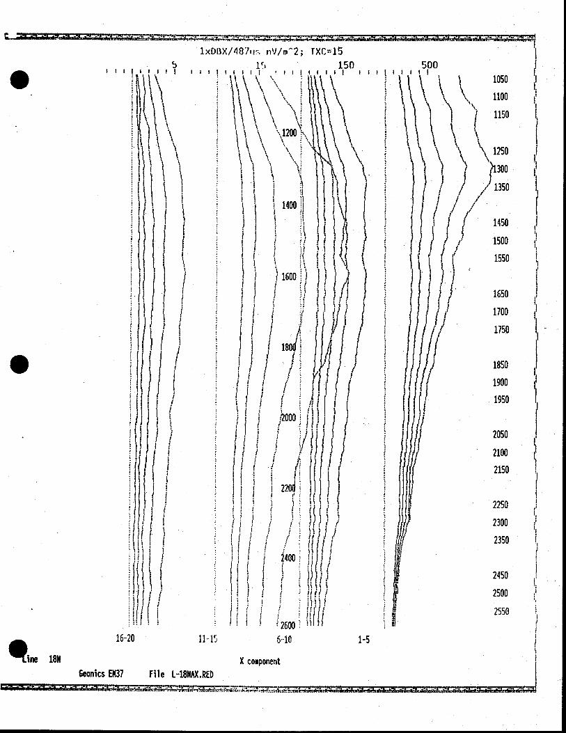
1xDBX/487iu:. nV1m2; TXC15
S it ) 150 500 111)1 I III• IIIIl • 11111111 1111 1 1 11 1
\\ \\
\ \' I 1400
I I 1 iI 1 1
I c II I I
II 1 1 I I /
1 1! 1 I ) / 180
I I
1 i I 1
I II I I I Ii I I I
1220 it1 i I
I I
I I
I; I 2400
H I I
I I
I((1 I 1 2600 16-20 1115 6-10
18N X component Geonics EN37 File L-18t4AX.RED
Big 1-1 NO CA NO
1050
1100
1150
1250
1350
/ 1450
1500
1550
1650
1700
1750
1850
1900
1950
2050
2100
2150
2250
2300
2350
2450
2500
2550
I I I
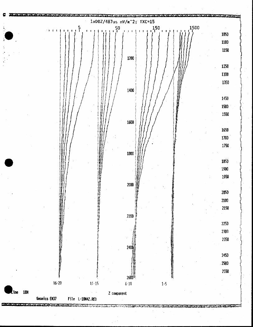
1xDBZ/487u nV/in2; TXC45 5 50 150 1500
IIII IIII!III ;;It!IIII III 11111
H/ / /Uf I J 1)//1200 HI
1400 Ii 1
if I
1600 ii I f d ' I
1) 1 IIIII : S
J u fl/i I !1I1I ti fJJ, /
n 1800 j!1 /
1 I11 in gift
i!U j AT
wr 2000
2200
2600111: WE
16-20 1..15 610 1-5
me 18N Z coiponent Geonics 0(37 File L-18NAZ.RED
1050
1100
1150
1250
1300
1350
1450
1500
1550
1650
1700
1750
1850
1900
1950
2050
2100
2150
2250
2300
2350
2450
2500
2550
1
.15
I I
11
/11
/ I Ii
I I
j I I
I If
I t
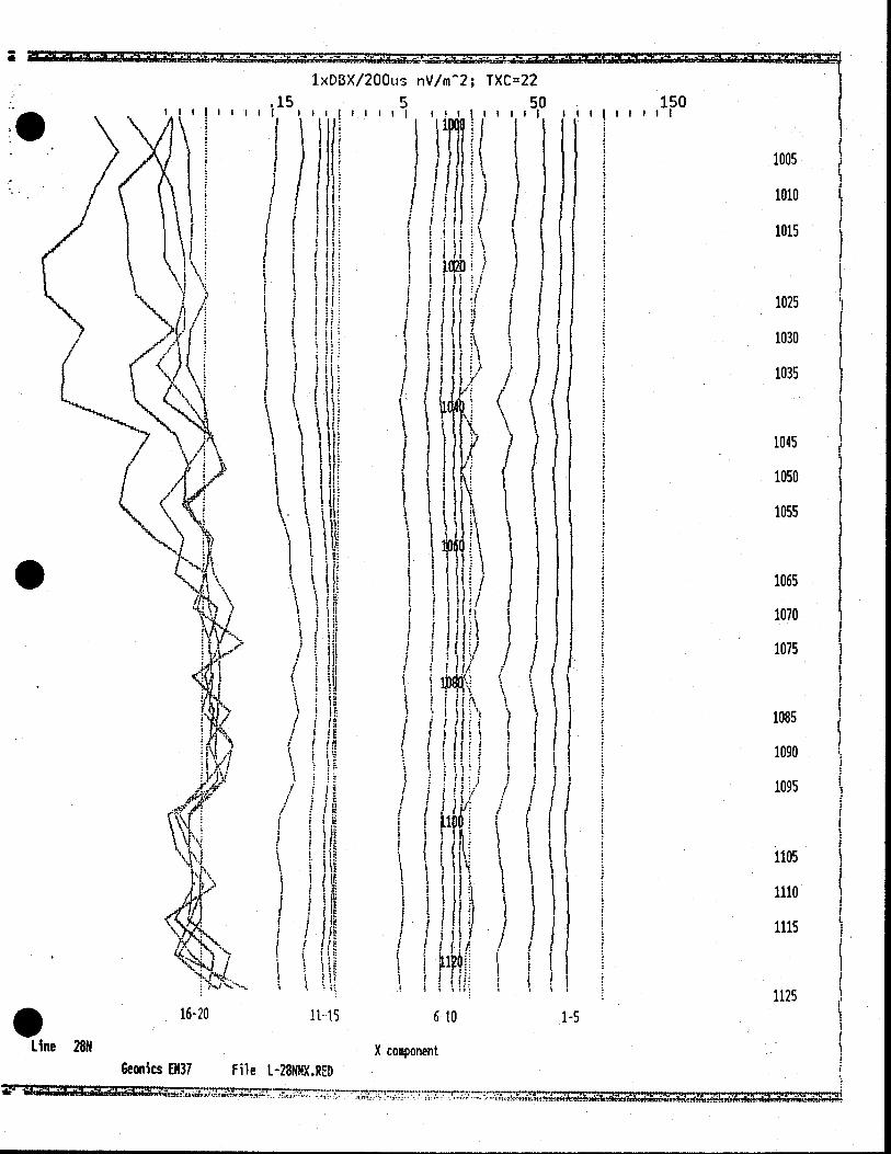
<DBX/200us n'
5 I!
$ /
I t
I I
I I I
/m2; TXC=22
if
AA
I (JI I
I Ii /
I
'I
\ ;
i LY• /
Ii
150 'I
11111
-
I I
16-20 1115 610
Line 28N X component Geonics EN37 File 1-28N11X.RED
1005
1010
1015
1025
1030
1035
1045
1050
1055
1065
1070
1075
1085
1090
1095
1105
1110
1115
1125
1-5

.5 I 11111 II!
•\ (H 11 ?1 ,( 1%
I I i •
\ II if \ 1 '
lx DBZ/200us 15
I I I I
H /
/rn'2: TXC22
I I I III 0p0 ii
(t 15
020 /
\ tYi \
I H / /
500 I I I ill
1005
1010
1015
1025
1030
1035
1045
I 1050
1055
S
If 1065
1070
1075
\ •\\• Iiu1u \1 '
I ?I.t I I ii1 I)
/ I ( 1100
f t III I IIi I I TIH ifH !
)
I III. IIiI. t
I 1.20;
It I I H H I ( 16-20 11-15 6-10
Line 2811 Z component Geonics 0(37 File -28NNZ.RED
l
1085
1090
1095
1105
1110
1115
1125
.5

I .r3/1 8o11. iiv/rn 2; TXC18 .2 5 0 150 1500
ItII tit
(i1 '
J 960
I f 965 I
ii lt\\ 970 I S I J
: 1 11k liii .
k 985
. t
0 990 J hI I :l IhI \ I
j I 995 s
• . : r Ii i 1%
1000' I 1 1 II
I. •i '1
1010 5 •
I ) t ) r 1015
I 11020; 1 • ? i I ! 1025
1 1030
1035 • p r
!'HI1010 Jfl 1015
tHi ( 1050
i'f ; ? •u ( '5 / f : iii I I i/l I I IVU. f iI,ji
js ) ii , 1 5 IsIs'
1065 1 1 IN : J j U111
I I F jFTJ S
I 1070
S :
1 ••I5 j it 1 j iII 1075
:1 1 .5 / •;;; / / : I hilt //f i
LUOU:
•iti1 f /1. II! 1085 III I I I I I I I I
1090
/ ! • :5., .5 ........• 1095
16-20 U 15 6..10 1-5
Line 28N X component GeonicsEN37 File 1-28N8X.RED
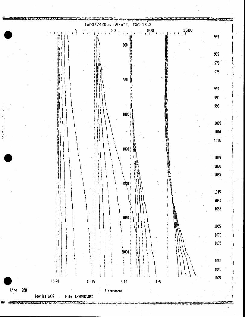
1x3Z/480us 11V/m7 TXr.48.2
5 50 500 1500 f!III III I 11(11 III
M.
1 1 1h1 t
j 960
I I
'I.
980
1 iIII\ iI I 1.
\\ \
1000
S 1 ( I
I itj I
i 1020
1 1 1 1M,
S I II I 1
• It.
5 5 1 15 ti I S
I 1
(is 1 1 1 I I
1040 j I
II I I fIll1
5 5k 5
I I I! I \It
'Ii 1 1060
1w HIt I I I
I :Ii55 fl
I I I I S 5 111 :fI :1I1II tIj 1 III5 I Ii Ii' I L S
t1080 I
I rf I ii 1 II'
II I Ii, 1
16-20 HiS 10 1-5
Line 28N Z component Geonics 0437 File 1-28NB1.RED
. 955
965
970
975
985
990
995
1005
1010
1015
1025
1030
1035
1045
1050
1055
1065
1070
1075
1085
1090
1095
985
990
995
1005
1010
1015
1025
1030
1035
*
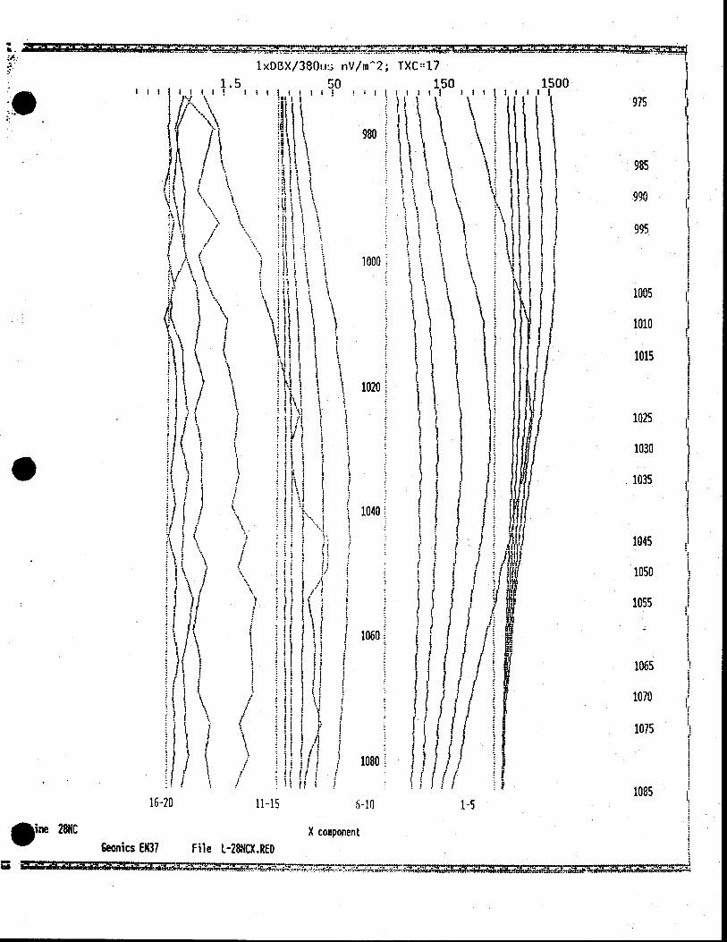
1xD8X/380i.r nV/in2; TXC::17
1.5 50 150 1500 • III I!lI !IIIII 11111!I II1IIIuI
980
\
! 1 S I
11 5 I 1000
\ \ t
I \ \ 1020. I I I
I! I - vi i
I I I •1,
i 1
•It / \ 1040 H 1(11! 'I I
\ : ' $ I I S
tlt.
/ \ :i r : J •1S.Ii)
ji • I 'I
1Il I
I !I(Ik' I if iriI I1060 iiJI
!i1.I I
I (1
i ' HII P I
1080
16-20 11-15 -10 1-5
•ine 28NC X component
Geonics EM37 File L-28NCX.RED ra
975
1045
1050
1055
1065
1070
1075
1085

1XDB7/180,is nV/m2; TXC=17
5 !0 500
III! II !,!I,j,t: !ilil!II III if I :fJ I I H I I
(980 1' I / I ?
( I!
i t I j '
I i I ii I I I I ,i IiS.
(1000 h iiJ i I t U
1500 I I I I I
IJ i I I '°° 11i) I I I I HI/I
I I / ;/,; I
1 1 I I 'fill'
1
Il I H I I ii I
/ 1040 j
: t i
11
1060
ij
I Ni i •1 I I ui i
J j I
I 1080.
S 16-20 1115 6-10
Line 28NC Z component Geonics EM37 File L-28NCZ.RED
1'
985
990
995 '1
1005
1010
1015
1025
1030
1035
1045
1050
1055
1065
1070
1075
1085
1090 1-5
.
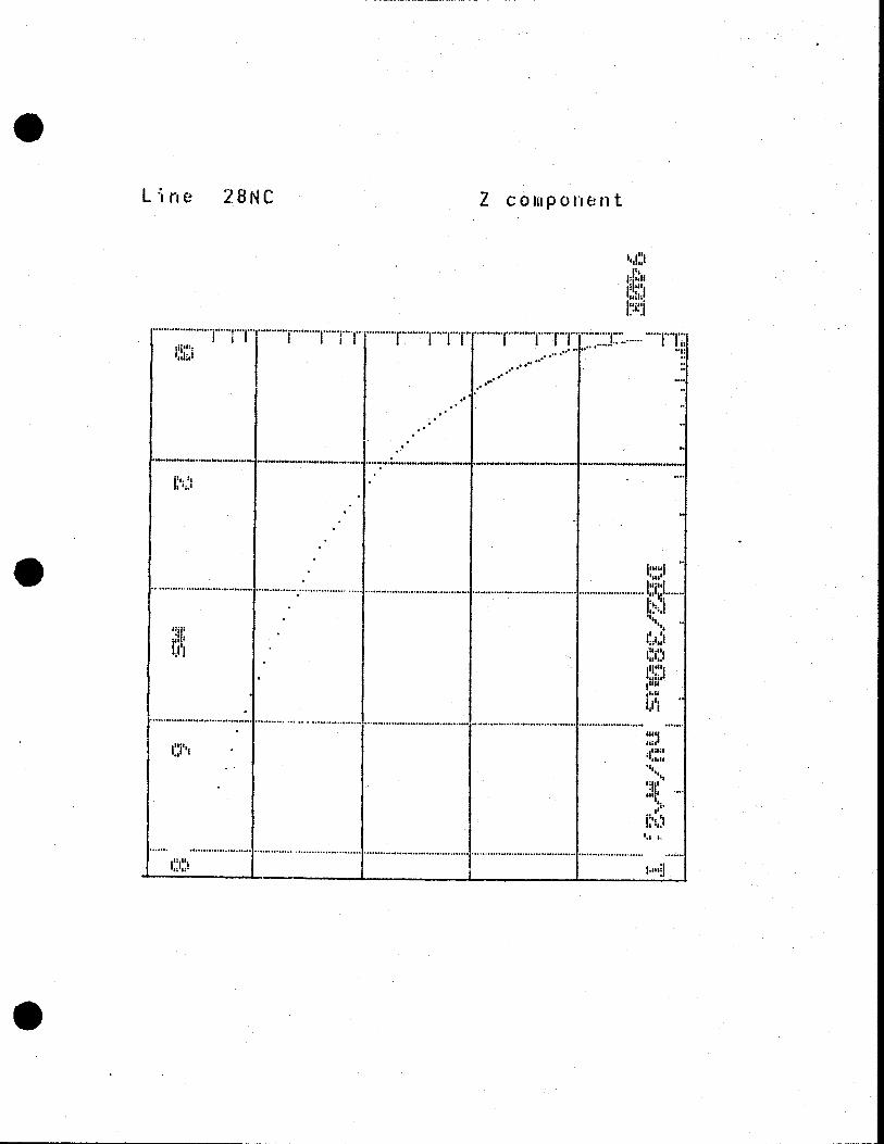
Line 28NC Z component
tsl
.
0
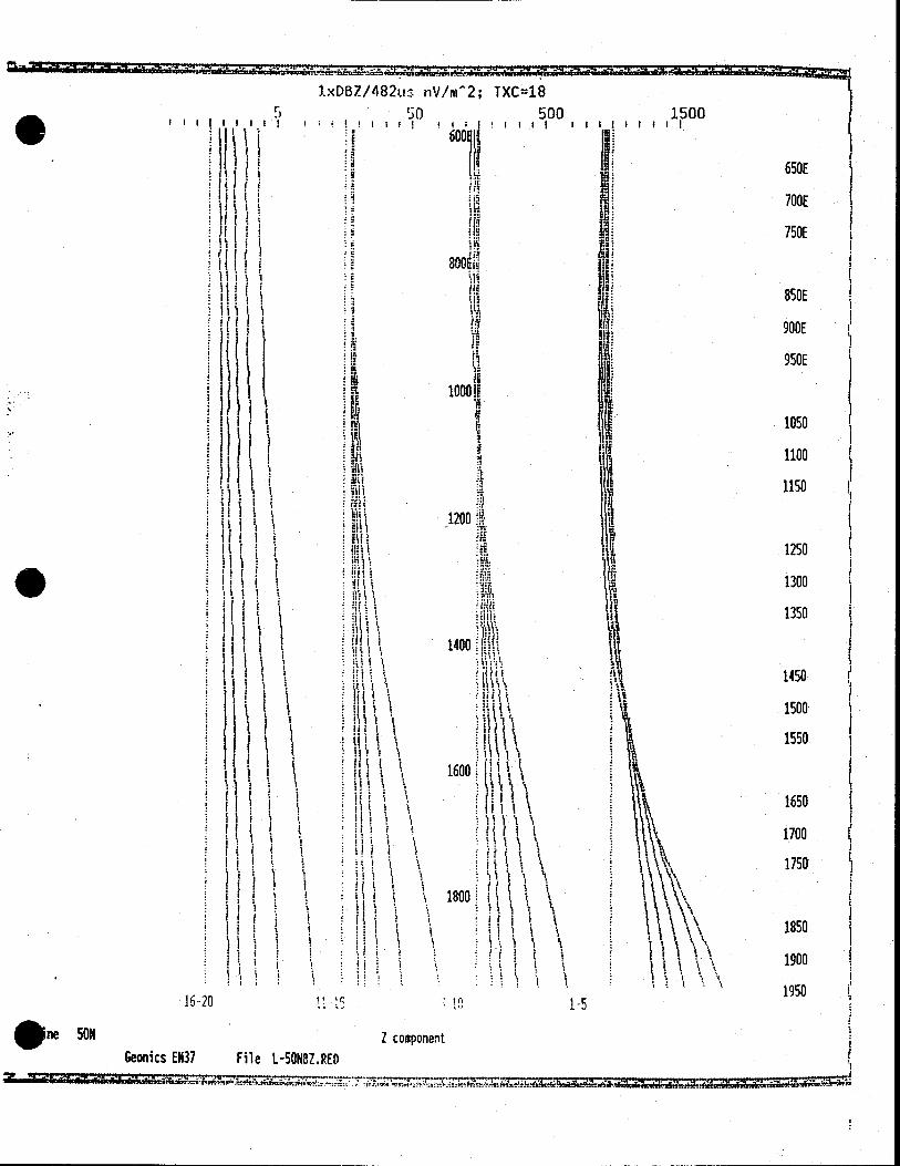
1xDX/1St; n'J/m'2 rxct7 5 150 1500
-
11)f/48tj nV/m2; TXC - 17 is 500 1500
III! Ill I I!'I III • !'lII Ill I 11111 III
/Aoo • •
t c ' 1200, hI!
M jj 1 J I iiI :l
Ii I I I• iI t
II!1 4 :tIt
:llfl it: I fl(
lilt I I! I
iuu ti't tIJ I
I I
III i(( F I
I I II
111 1! !llI I iii iii
li'lIl iiiI 1iit it 11(1?
IN'! 1600 ur
I I! It Ii. iI (1
•If 4 f ill/fi 1800 L
1R. I
it UW
I III
till I I I -. 1 1:1
II I
Mil Nt
-' 41
ii lI 2000
ill III I u
IN] I ha 1I
it U.: I 22
p. 226 "1
Mi
TI r 1620 ( 11) 1-5
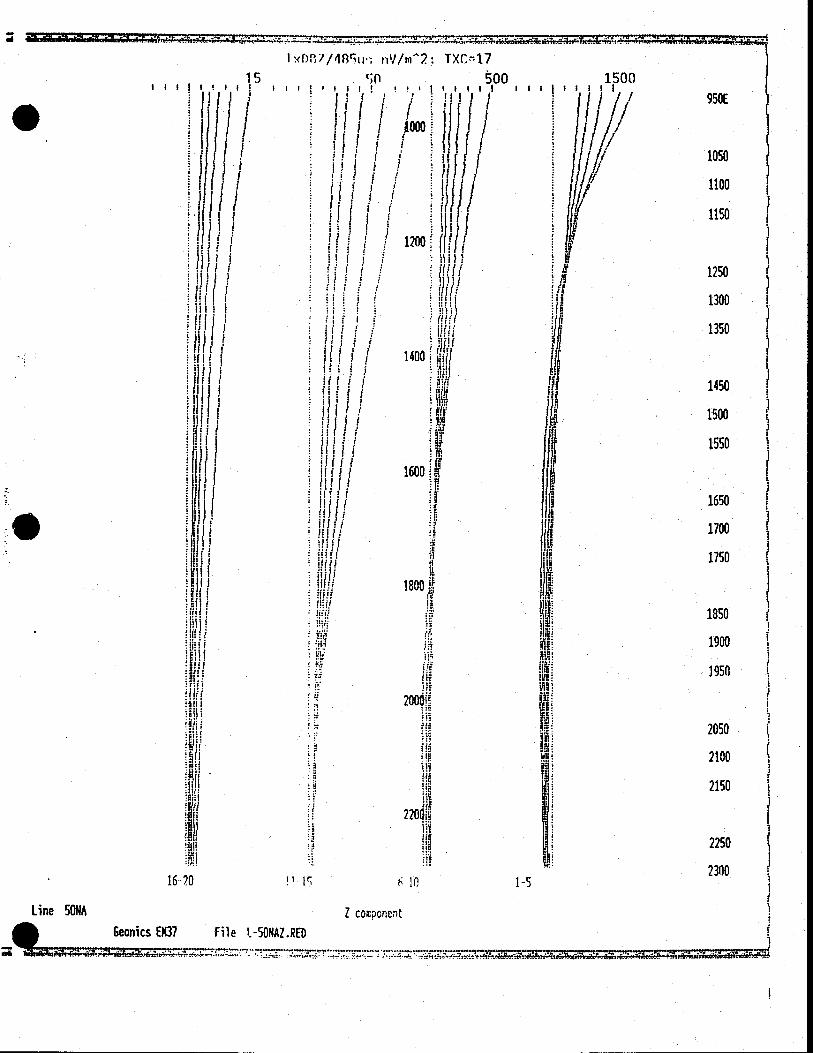
Line 50NA I component Geonics EM37 File i-50NAZ.RED
950E
1050
1100
1150
1250
1300
1350
1450
1500
1550
1650
1700
1750
1850
1900
1950
2050
2100
2150
2250
2300
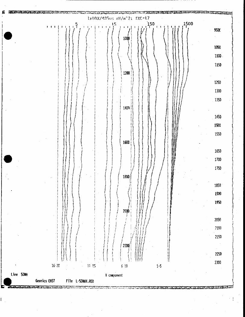
lxDBX/482u nV/m2; txc=i
1.5 15 150 1500
IIIIIiI I! ! 600E ,iilIIII IllIllI l l
I J\J j 650E
' . • 700E
/ 800E (
.1 850E ii
1 / 900E f ' I
950E
1 f I
\ 1150
S1I Afl \1200d.. '
\ s 1250 I \ I I •.
R\ \ 1300 w '1
1350 (II •/ I
• I ( / I lAflfl ( / C • •
I' 1 1450 • 1 :1
f f i \! 1 1500
1>1 4 1 1550
1600
I I ii 1 1650 I r I V II
1 1 •iI 1700
1750 I 1 1800 3
/ • / ,- • f I/I I / / 1950 16-20 11_15 6 1 1-5
line SON Geonics EN37 File L-5ONBX.RED
X component
- - .- - -.. ---•--•---•_---....-......_- --_...------.--..-.-.---- -..-.--------------
I
U
I
I
II
P; ' I
If
I?,
ii I' i •1
1xDBZ/482u: nV/rn2; TXC48 5 50 500 1500
c.I cit i 11111 Ii!
600
800
if
1000
H HI i
I. if I f
f lit ( I I EiI1
ii I i
If I I I
Ii ( II, I it
I I II.
t I .t L
Ii i i ill! 1.1 1 Iii 1 I I I t
if I I I H! I
Ii •i (If I I i I
I. f '.1 • 1
File 1-SONBZ.RED
I
I I!
i i
•
16-20
•ne 50N Geonics EM37
1200
1400
1600
I 1
1800
1 :1
I I
in
1-5
Z component
650E
700E
750E
850E
900E
950E
1050
1100
1150
1250
1300
1350
1450
1500
1550
1650
1700
1750
1850
1900
1950

950E
1050
1100
1150
1250
1300
1350
1450
1500
1550
1650
1700
1750
1850
1900
1950
2050
2100
2150
2250
2300
I
If/I
III 1 1 I
fit I I H' Hi I I lit I I ii •
I I ii S. ! I I •
II! / III F F (IS I I 131 1 (11 1 1 iii ( I
1 J ilj II!
.1 3 It' I III
I /
1620 11-15
58M Geonics EM37 File 1-58NAX.RED
175u3 nV/rn2; TXC47 150 1500
loco
ill '!iiuiiI ilulilill
1200 \ • L 1 \ It
131 : Ii 1;
1400 (
I I I I I 11600
'I I
II J It
I /
f / (1
2000 /
H I! 2200
1/ IL 6- io
X component
I I I
1xDE3X
ci
II I
,
I •' \ I
fl 1) 7
I 1 I
J / /
/
F I
Il ii
'I It
it if II ii ii
. I
1-5

0Z/47 1 Ll tiV/rn2; IXC - 1.7
500 1500
I 'I ii i I
/ /1 11/1/ /
/ H 1200 H( 1 I
is I
Sli 1 5
I
h f
U S Y S :i/r/
II 5 11ii
11' 5 /f I'
1600
I 'I
fl S ill I
I/JI t800
WL
I
1 2000
H J1
i ?201
1115 •10 1-5
Z component
! ( I I I!
tJ, / I
!I 1 U S
I s5
bUt 16-20
950E
1050
1100
1150
1250
1300
1350
150
1500
1550
1650
1700
1750
1850
1900
1950
2050
2100
2150
2250
2300
Geonics E37 flie L-58NA2.RED
J 2140
I I
2160.
I fill I
1111 f fill I
III I I I •1 I
I Ii I I ii I III I I :111 I I IIi I
I I I 11 1 I
I1 1I
I' I I II I
I II I I • ' 2200
16-20 11-15 6-10
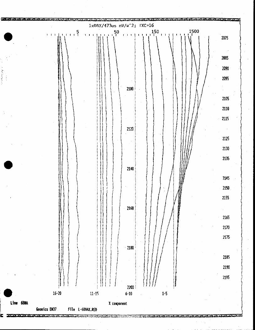
Line 68NA X component Geonics E37 File L-68NAX.RED
--
1-5
I'
2100
If
I 21201
I I
i
2075
2085
2090
2095
2105
2110
2115
2125
2130
2135
2145
2150
2155
2165
2170
2175
2185
2190
2195
109X/473us nV/ni'2; 1XC16
5 50 150 1500
111111 III I I4!II Ill I $1111 III I IIII ill
i \\ U
I
I J
I if I .1
/
I j
I
it ( f I /
I f
I I j
1(1
(I ,
nI 2120:
HI 2140
1
01 2160
I II
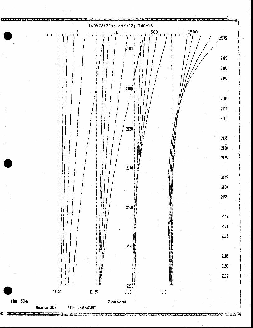
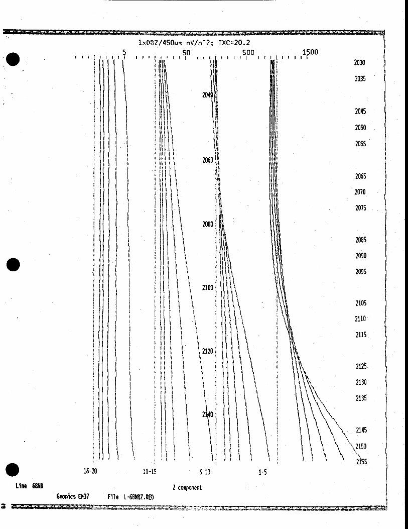
1xDRZ/473us nV/m2; TXC16
5 50 500 Iii I iiI iii III
!'
/1 / / ' L(/ F!'
12100
Ill!!
1500 I I I I t
HH/ ff
1620 11-15 6-10
Line 68NA Z component eonics 0137 File L68NAZ.RED
2085
2090
2095
2105
2110
2115
2125
2130
2135
2145
2150
2155
2165
2170
2175
2185
2190
2195
1-S
.41 :
1xDBX/ 1.5
III 11111 I
/ ) I I ( j
i' I / /
II / •1 ii
I I i,g j
I i /
/ / H
450us nV/m2; TXC20.2 50 500
!;II i;I(II'.II III I I i f
I I /
/ 2040
I I / lII /
I If I
A i .11H
1/ 2060
/1. I I i 1 111
I
2080
1500 II ill 2030
2035
2045
2050
2055
2065
2070
lilt . 2075
2085
\\\ ::
2105
\
2110
i \ \
2115
I t 2125
\ \ 2130
I 2135
) 2145
2150
2155
w (
Ii
H I I IL I
il I (1 2100! I
II I / iI I
Il'
f (
•)\
/ I!
I? ( 5 I I aim! H
Wi I I J L.LLU I I
I I Ii 1 5
// j •/ :11 ( / :1/ i 'i I II
I I 1 1
IIII I I
ii t I I II
1 I
'li't I iIj I Ii
I / 2140
I I I LI I I / fl/i I •U! !
J IC C
16-20 / 11-iS 610
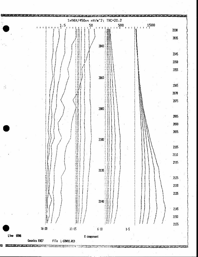
Line 68NB X component Geonics EN37 File L-68N8X.RED
rd ..........
1-5
•
. 16-20
Line 68N8
Geonics EN37 '
I ' 1 ~
II
' \ 11-15
e I. -68N8Z.RED
2035
2045
2050
2055
2065
2070
• 2075
2085
2090
2095
2105
2110
2115
2125
2130
2135
\ 2145 \\
\2150
I
I I I
lxOflZ/450us nV/m2; TXC20.2 5 50 500 1500
IIII If!!1;1;! 1111,1111 IIIIIIIII 2030
IN
H (1 20601%
ii •1
H li
SI n
it\ 2080 ~ •i
lit \ II "• \ Ii I
I ~ III S I 2100!
5 I I 151 1 1 I I hi ti
I iSs I'.
5 5 5 IIj
t 2120 1
•i ; I \ I I (I I 1 1 it 1 S
I I S I 5 1 515 ~
l\ 2i40 \\ \\
) t(
6-10 1-5
Z component
:1
.
I
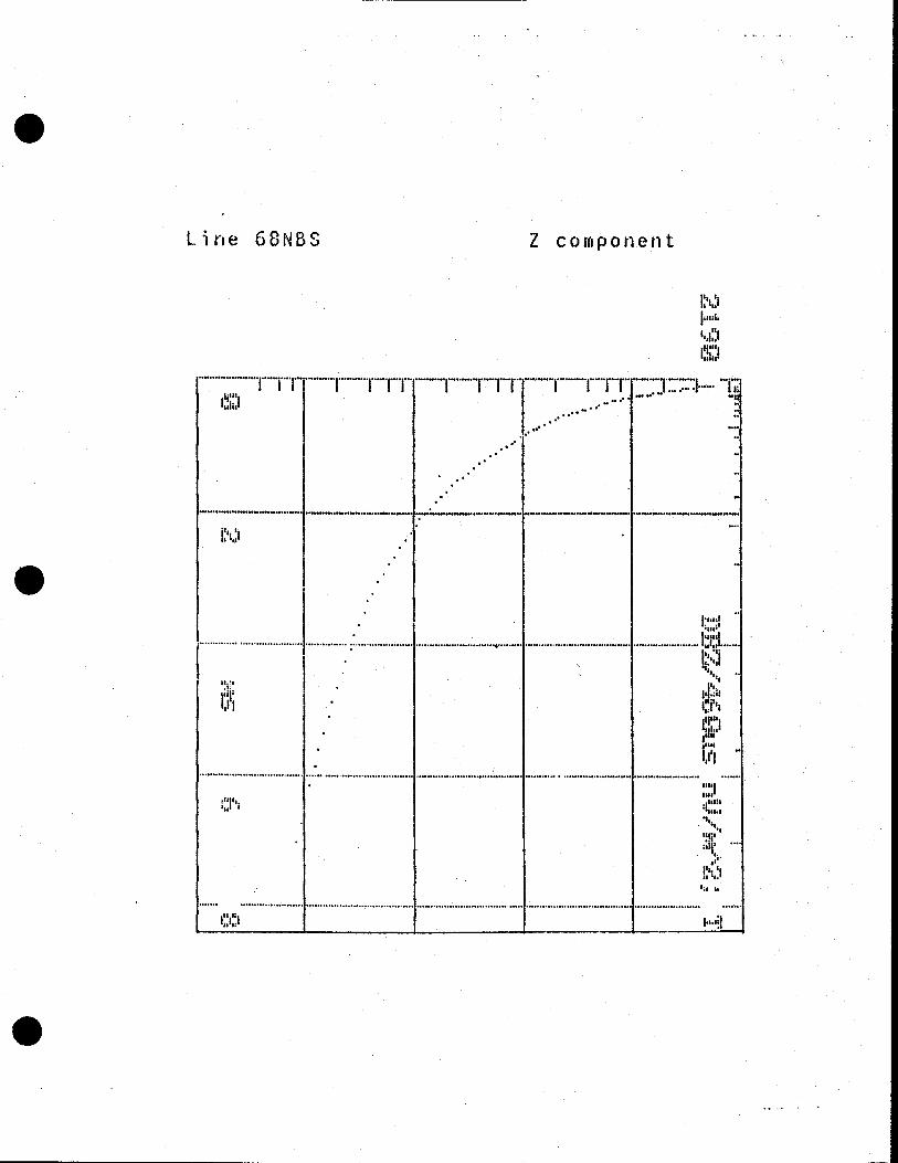
Line 6ONBS
Z component
.
Ihiahhl
•..•.....•....•..
IutuI 'III,
I .
uil I
1141 tiI I
I II i . Ill..
I.'
.1' •
I" - II
14, 4
0 I

, I I I
.
1xDBX/220is iV/m: TXC17
5 50 150 15( lilt! hIlt! Ii! !I!4hll! III 11111
\ \ \\ \\\
\ \ \ 1560' \ LII P1i I k IIt f t
\ I p '. . \\ •' . 'i '
I. 1 'I
i f \ \ \
\1580\ \ \ ))
1600 3 / 11111/ YIi j j1 / Jill/f
f I 4 H; jij
1620
If U j. / -...
J1I 1640(H .JJ
(I 1411 I * Ii
111 111 I.
1.TJ ll :114
:1
1660
1115 6lfl
Line 92HA X component Geonics EM37 File 1-92NAX.RED
UI.
:111
1-5
1555
1565
11570
ii
/1575
1595
1605
1610
1615
1625 If
1630
1635
1645
1650
1655
t665
1670 If
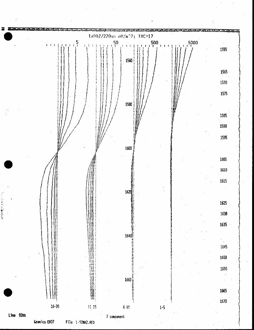
1xDiZ/220u: nV/rn2; TXC1 7
5 50 500 5000 !! !!IIl IiIfIIII
( ' •l :l. l I : j . I :
ii I jii I 1 Hi I ( I '
ill I I I1i I 1 lii j
I 11 1 1 15601
11 i / 1 : NUll 11(1'
it I r I uuf Ii I I 180 ii?!
/1 U/tf
il I I iii / II.4
NT
1%! 1 it
1600k
I I I
1555
1565
1570
1575
1585
1590
1595
• /'//4 f / I I iIj
' i •
162i
I iItt
Il Iil1
1640
ui
:. I I'
IIi I
j I 16601 '1
• 1; 16-20 U 15 6IC
Line 92NA 7 component
Geonics E937 File L-92NAZ.RED
1605
1610
1615
1625
1630
1635
1645
1650
1655
1665
1670
1-5

1•
I) /
1625
1630
1635
1645
1-5
1xI3X/220us nV/n(7; TXC -46 5 50 150 1500
ll!I !f!II! i!!'fI! Iii II!
1530
I. IuI 1535
1540
ffl i
t!t 1550
1555
\ \ 1560
tn ':\ \
1565
It s \ t 1570
t ••n\ \ k
I 11 1575 i l
1580
1585 \
1)11 1590
I ) I H 1600
) )
1610
/ / I H iii F II 1615
'LI /
• H /
-. IH(f
1620
I I / •(ff f
I /
I'
•
1640
16-20 11-15 10
Line 92118 X component Geonics EN37 File L-92P16X.RED
I
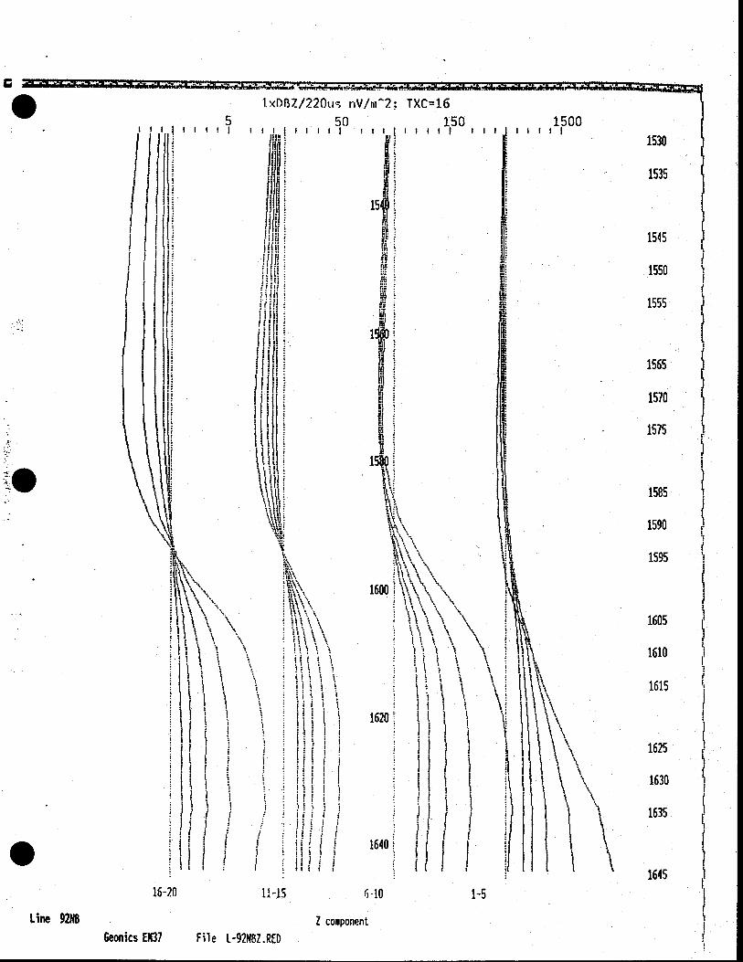
.. 1.xD87/220u riV/rn2; TXC16
5 50 150 1500 IIII! I IlillillI f!IIIII ill III
1530
• 1535
'ph 154
1545 I!
tif 1550
C, 1555 I1
I
fill it 1565
1570
1575
1585
Ali 1590
1595
1600
\ \ \ ' \ \
•!i j
I, k I
' 1620
I J( I
1640 - W I f I
16-20 11-15
Line 92NB Z component Geonics EM37 File L-92N8Z.RED
' \ \ \ \\
\ t\
I \ \\\
( 1 1• \ \
t\ \\\
I t I I ii
1-5
1605
1610
1615
1625
1630
1635
1645
I I
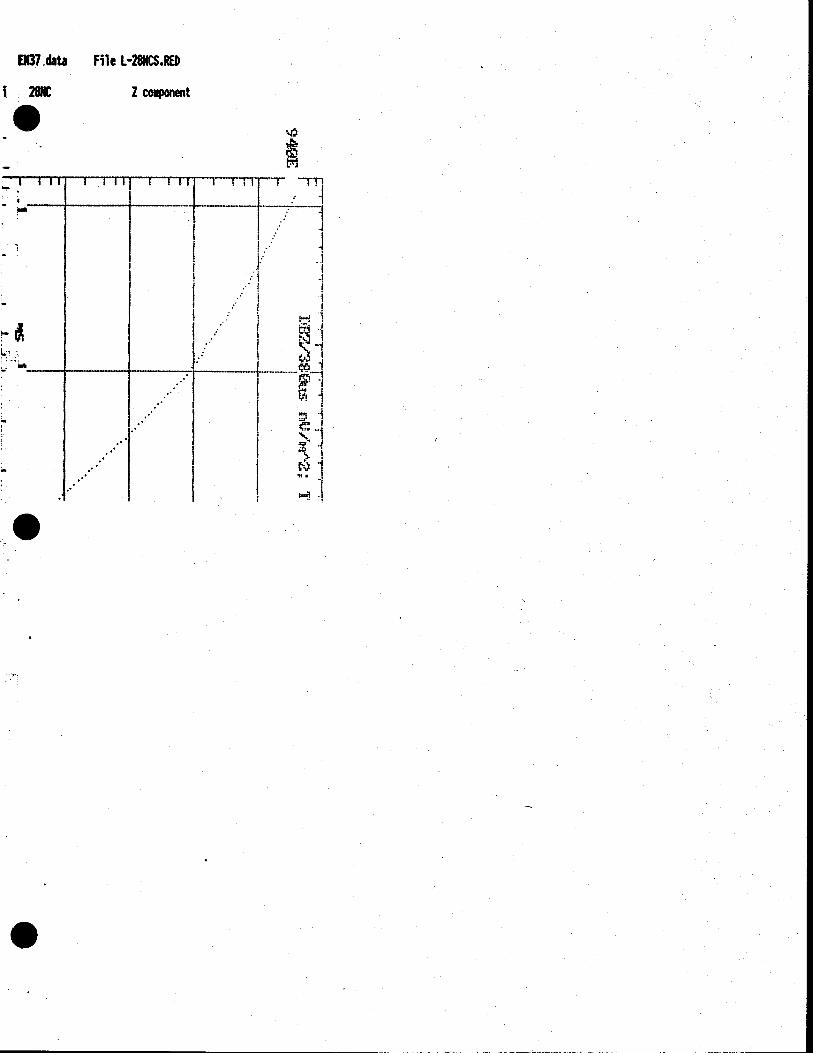
E1137 data File L-28NCS.RED
I2K 2 cnt
0