manufacturing status review - colorado
TRANSCRIPT

Aaron Buysse
Chad Caplan
Matt Holmes
Colin Nugen
Kevin Rauhauser
Ryan Slabaugh
Rebecca Travers
Proximity Identification, chaRacterization, And Neutralization by tHinking before Acquisition (PIRANHA)
Manufacturing Status Review
8/24/2014 University of Colorado Aerospace Engineering Sciences 1
Team: Advisor:
Dr. Jelliffe Jackson
Customer:
Barbara Bicknell
Jeffrey Weber

•Overview
•Schedule
•Manufacturing
•Budget
8/24/2014 University of Colorado Aerospace Engineering Sciences 2

Facts • 80k objects greater than 10cm
• ~60k in LEO
• Threat to assets and astronauts
• No active counter measure
8/24/2014 University of Colorado Aerospace Engineering Sciences 3
Data of debris > 10cm in LEO, MEO, and GEO1
Purpose Schedule Manufacturing Budget
8/24/2014 University of Colorado Aerospace Engineering Sciences 4
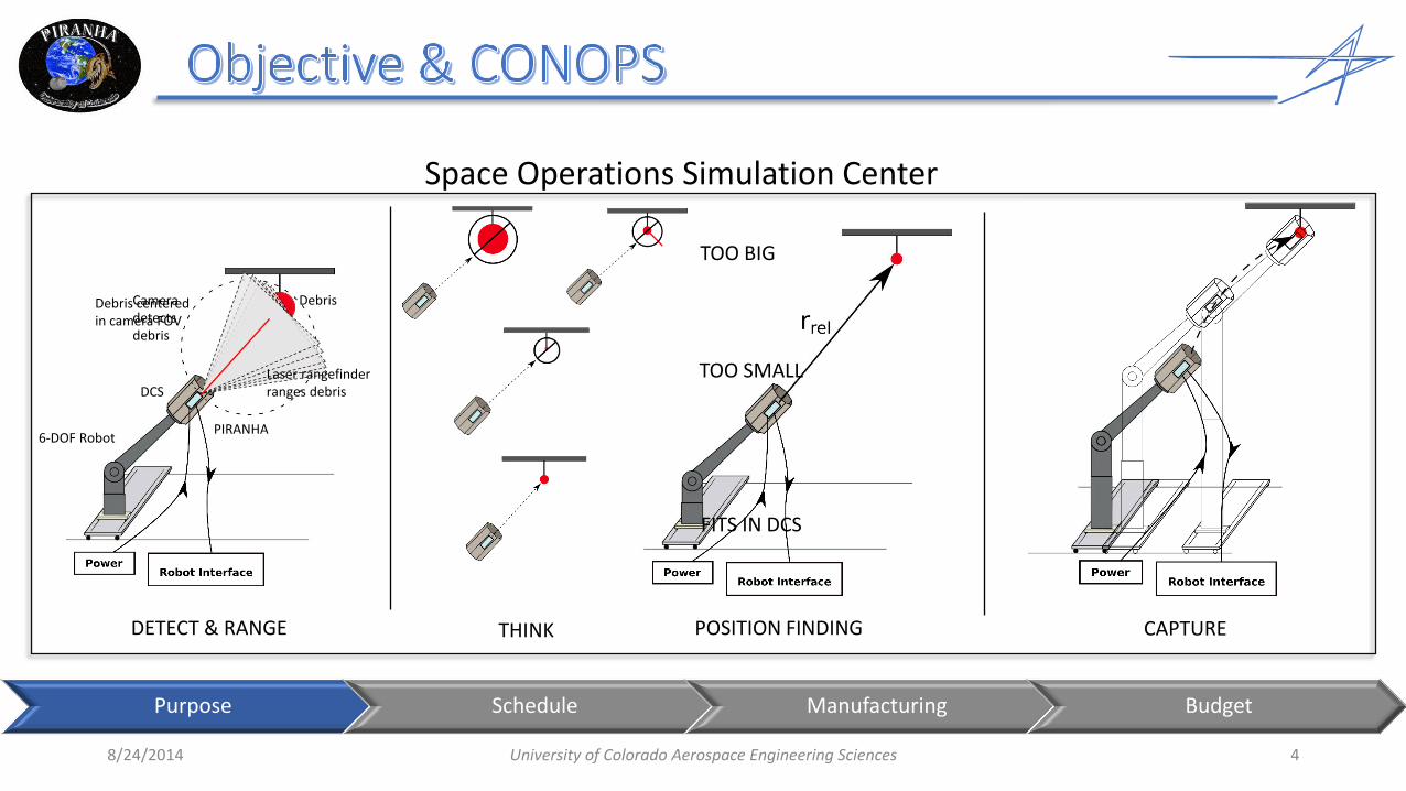
DETECT & RANGE THINK CAPTURE
Space Operations Simulation Center
6-DOF Robot
DCS
PIRANHA
POSITION FINDING
TOO BIG
TOO SMALL
FITS IN DCS
Debris Camera detects debris
Debris centered in camera FOV
Laser rangefinder ranges debris
Purpose Schedule Manufacturing Budget

8/24/2014 University of Colorado Aerospace Engineering Sciences 5
Space Operations Simulation Center
Stage 1 Stage 2 Stage 3 PIRANHA: - Calculates, stores
debris relative position vector and DCS attitude
SOSC Robot: - Runs trajectory using pre-canned
attitude & ephemeris data stored on SOSC computer
SOSC Robot: - Runs trajectory using pre-canned attitude &
ephemeris data transmitted from PIRANHA
SOSC Robot: - Runs trajectory using pre-canned
ephemeris and real-time attitude data transmitted from PIRANHA
Ethernet Ethernet

8/24/2014 University of Colorado Aerospace Engineering Sciences 6
MSR Week 8 Week 12
Mechanical Electrical Software Systems Test Class Milestone PIRANHA Milestone
• Converting Simulink/Matlab to C
• Hardware Component Tests
• PCB Power Board • “Hello World” on SBC • Machining Gimbal
Bracket
Validate Design in SOSC Mar. 27th
HWIL Phase I
Added – Consolidate software into 1 main program
Added SOSC Testing Feb. 11th
• Fit Check DCS to Robot • Run Scenario with DCS
attached • Transmit data structure from
SBC to SOSC
Software Phase II
HWIL Phase II
Verify Requirements
Purpose Schedule Manufacturing Budget

Choice of Voltage Regulators • Power Consumption Limits
• Proper Voltage
Trace widths • Board will draw a current of ≈5A in worst case
scenario • Equates to a trace width of 110mil on main line
Connectors to suit power needs • Input power was changed from header pins to
banana plugs because of expected current
Designed with SOSC Constraints in mind • 60V, 10A, 600W power supply limits
• Chose 15V input at a max of less than 5A
8/24/2014 University of Colorado Aerospace Engineering Sciences 7
Purpose Schedule Manufacturing Budget

Power Board PCB • PCB designed, ordered, and arrived
• All other components ordered and arrived
Testing • 15V power supply, no loads on output pins
• Voltages on all output pins measured in reference to board ground pin (ground pin referenced to power supply ground)
8/24/2014 University of Colorado Aerospace Engineering Sciences 8
Description Output Pin Expected (V) Measured (V)
Ground GND 0 0.00
Laser Rangefinder RNG 15 15.08
Single Board Computer SBC 5 4.90
Camera CAM 12 12.00
Servo 1 SER1 12 12.04
Servo 2 SER2 12 12.03
Fan for Heat sink FAN 12 11.95
FNC.5 - Testable in SOSC
CPE.4 - Integrate with SOSC
TSR.2.1, .3.1, .4.1 - Camera, Rangefinder, Single Board
Computer
Power Board Completed: Jan. 24th
Deadline: Jan. 27th
15VDC

Power Board • Individual components have been powered off
of board
• Full load test • All Components powered and running with
expected loads for the capture scenario
• Utilize main program as it is so far
• Determine Interfacing Connectors for distributing power
Electronics Box • Integrate Power board and Single Board
Computer
• Determine where holes need to be for mounting and cables
8/24/2014 University of Colorado Aerospace Engineering Sciences 9
Power LED
Ground
15VDC
Camera
Purpose Schedule Manufacturing Budget
Integrate to electronics box: Mar. 11th

8/24/2014 University of Colorado Aerospace Engineering Sciences 10
Camera
Raw Image
Image Processing
Servos
Debris Centered?
Rangefinder
Debris Edges
Calculate Rotation Angles
Size Characterization
Pan & Tilt Angle
Capturable?
ALERT DCS
Calculate Quaternions
Servo Interfacing
Data Packet
Camera Interfacing
Rangefinder Interfacing
Debris Range
Debris Size
no
yes
no
yes
FNC.2 – Detect debris 10-40cm in diameter at
20m
FNC.3 – Characterize debris by size to within
±2cm of actual size
FNC.4 – Calculate position of debris
relative to DCS
Software Flow Diagram of Capture Process: Driving Requirements
Software Trigger
Software Trigger Centroid
Detection

8/24/2014 University of Colorado Aerospace Engineering Sciences 11
Image Processing: Detects edges of debris. • Tested & verified in C with SOSC test photos. • Obtained image processing filters from open source
computer vision software.
Centroid Detection: Determines debris centroid and number of pixels occupied by debris.
• Tested & verified in C with SOSC test photos. • Written by PIRANHA team members.
Size Characterization: Calculates size of debris given range.
• Tested & verified in C with SOSC test photos. • Written by PIRANHA team members.
SOSC Test Photo at 20m Zoomed debris after image processing
Debris
Size (cm) using C Size (cm) using MATLAB
Minimum Size 8.376 8.602
Maximum Size 11.04 9.218
Mean Size 10.03 8.902
Standard Deviation
0.792 0.229
Actual Size: 10.20 cm
Calculated centroid for all test photos in SOSC and calculated size to be within ±2cm of actual size.

8/24/2014 University of Colorado Aerospace Engineering Sciences 12
Calculate Rotation Angles: Calculates rotation angles required to center debris in image.
• Tested & verified in C by comparing output to MATLAB results.
• Written by PIRANHA team members.
Calculate Quaternions: Calculates the quaternion of the DCS required to capture the debris.
• Tested & verified in C by comparing output to MATLAB results.
• Written by PIRANHA team members.
Convert all functionality software to C and perform Software Phase I testing by Feb. 3.
Calculate Rotation Angles
Centroid of debris throughout
capture process
Pan & Tilt Angles compared to
Simulink model
Calculate Quaternions
Range of debris Quaternions compared to
Simulink model Pan & Tilt Angles to range debris
Purpose Schedule Manufacturing Budget

8/24/2014 University of Colorado Aerospace Engineering Sciences 13
• Integrated with FlyCapture C library • Used Linux native drivers
• Communicate over Ethernet with
packet size of 9000 bytes and packet delay of 6250 ticks (~5 × 10⁻⁵ sec.)
• Each image requires 2.8 Mb of memory
• Main code able to consistently trigger camera and acquire images
• Trigger laser rangefinder through RS-232 serial port
• Baud rate of 9600
• Outputs range in ASCII decimal format
• Main code able to consistently trigger rangefinder and acquire range measurements
• Command servos through RS-485 serial port
• Daisy-chained servos to command both simultaneously
• Commands inputs and outputs in hexadecimal format
• Able to command servos to angular position and get current position from servos in C
Two Dynamixel MX-64R Servos
Acuity AR1000 Laser Range Finder
Point Grey Flea3 GigE Camera
HWIL Phase I Testing - Integrate SBC with each hardware component individually by Feb. 18.

8/24/2014 University of Colorado Aerospace Engineering Sciences 14
Task Deadline Status
Convert MATLAB code to C & SW Phase I testing 02/03/2014 Complete – 01/31/2014
HWIL Phase I Testing 02/18/2014 Complete – 01/28/2014
Integrate all functions into PIRANHA source code 02/18/2014 Partially Complete
SW Phase II Testing 02/25/2014 Incomplete
HWIL Phase II Testing 03/18/2014 Incomplete
Tasks moving forward • Integrate function to calculate quaternion of DCS required for capture into main code • Integrate decision making logic into main code • Software Phase II Testing – Verify that all functions operate as required when integrated into main
code • Integrate servo interfacing functions into main code • HWIL Phase II Testing – Verify software can interface with all hardware and is able to track debris
Purpose Schedule Manufacturing Budget

8/24/2014 University of Colorado Aerospace Engineering Sciences 15
62 cm
90 cm
Heritage Debris Capture System
PIRANHA 20 cm
56 cm

8/24/2014 University of Colorado Aerospace Engineering Sciences 16
Rangefinder
Camera
Software and Computing Hardware
2-DOF Gimbal Assembly
Servos

Gimbal System • 2-DOF
• Camera at center of rotation
Purchased Components • Rangefinder, camera, servos,
bearings, fasteners
Manufactured Components • 2 Gimbal Brackets
• Ti-6Al-4V 3D printing at Lockheed Martin
8/24/2014 University of Colorado Aerospace Engineering Sciences 17
FNC.2: Detect debris at 20m
DES.4.2: Pointing & Tracking during entire capture scenario
CMP.2.1.1: Camera shall have 2DOF
independent of DCS
FNC.4: Pointing & Tracking Debris
CMP.3.1.1.3: Rangefinder rigidly attached to camera Tilt axis of
rotation
10.4 cm
7.1 cm
2.8 cm Gimbal Corner Bracket
4.8 mm thick
Camera/Rangefinder Bracket
14.6 cm
4 cm
4.4 cm
10.6 cm
Pan axis of rotation
Press fit bearings with pin
Laser beam
Tilt axis of rotation

Printed Bracket as Received
No Holes or Flange
Gimbal Brackets
• CAD models revised for printing
• Removed holes, camera flange
• Part requires post machining, assembly
• Printed brackets received from Lockheed Martin
• Defective bracket machined first – CNC mill
• Unfamiliarity with machining printed material
• Can assess dimensional accuracy of post-machined printed part
• SolidCam G-Code generated can be used for real bracket
8/24/2014 University of Colorado Aerospace Engineering Sciences 18
Camera/Rangefinder Bracket
Ball Bearing Press Fit into
Bracket
Camera Flange
Camera/Rangefinder Bracket Assembly Bracket After Machining
Holes Added
Front Edge Smoothed
Alignment Important Along Tilt
Rotation Axis
Tilt Rotation Axis

Gimbal System • Finish machining brackets, assemble system
Electronics Enclosure • Finalize mounting positions of components
• Will require addition of holes for fasteners, wires, fan
Mounting Plate • Aluminum plate material available
• Requires simple machining
PIRANHA/DCS Integration • Will need to add 4 holes to DCS side
• Mounting location determined to avoid bristles & structural components of DCS
8/24/2014 University of Colorado Aerospace Engineering Sciences 19
Mounting Plate 3/16” Thick Al
Requires 12 Holes
4 Holes Added to Side of DCS
Electronics Enclosure Fan, Wire, Screw Holes
Added
Gimbal Corner Bracket
Bearing and Screw Holes
Mechanical Work Deadline: March 1st

Rangefinder
• Measured ranges within required accuracy of ±3mm
Camera
• Able to take image
• Still need to test with lens (ordered but not received)
Servos
• Tested unloaded and loaded
• Pointing error greater than ±0.14˚ required
• Possible solutions: apply correction to command, control law, higher voltage
8/24/2014 University of Colorado Aerospace Engineering Sciences 20
Tapes 1m Apart
Rangefinder Aligned with Tape
Rangefinder Testing
Servo Testing
Bending Moment Case Lateral Loading Case
Servo Weight
Servo
Weight

8/24/2014 University of Colorado Aerospace Engineering Sciences 21
Expenditures
Electronics
Hardware
Mechanical HW
Miscellaneous
Budget Left Over
Future Expenses
Poster Printing
Miscellaneous HW Additonal Funds
• After future expenses ≈ $900, Aero department provides $500 for travel
• We have ≈ $1,400 for travel to the AIAA student conference
Total Expenses: $3833.54
Estimate from CDR: $3397
Difference: $436.54
• There were a number of small purchases overlooked at CDR • We no longer can repurchase some large components if
damaged • Not a significant concern due to the level of understanding of
the hardware at this point
Purpose Schedule Manufacturing Budget

8/24/2014 University of Colorado Aerospace Engineering Sciences 22

1 Bemner, Brian. "Cleaning Up the Final Frontier." Bloomberg Business Week. Bloomberg, 16 Jan. 2014. Web. 02 Feb. 2014.
8/24/2014 University of Colorado Aerospace Engineering Sciences 23

Slide Intentionally Left Blank
Slides here after are backup.
8/24/2014 University of Colorado Aerospace Engineering Sciences 24

8/24/2014 University of Colorado Aerospace Engineering Sciences 25
Purpose: This test is to verify that the laser rangefinder’s output data can be collected and stored by the single board computer. This will help mitigate risk of PIRANHA failing due to the software algorithm being unable to access range measurements.
Diagram of Test Set-Up:
Summary of Measurements:
Required Materials/Facilities: Requires the PCM-9362 (SBC) with Linux and use of GCC complier, AR1000 (LRF), DC power supplies of 5V and 15V, Computer monitor,
Measurement How the Measurement is Verified Related Requirement
Laser Rangefinder output range stored on SBC
Compare physical range of LRF to data transfer range
CMP.4.1.1

8/24/2014 University of Colorado Aerospace Engineering Sciences 26
-Using a C routine on the single board computer, pick off streaming range measurements at 6 Hz (fastest for rangefinder) -Some measurements unusable, and the rate decreased for dark objects LESSONS LEARNED - Original method of streaming range measurements is
difficult. - Investigate alternative to buffering a stream of
measurements
Unusable

8/24/2014 University of Colorado Aerospace Engineering Sciences 27
• Purpose: Verify the rangefinder can accurately range targets within the tolerances specified at the ranges needed for testing in the SOSC. Test will mitigate possibility of failure due to defective rangefinder
• Diagram:
Distance = 1, 5, 10, 15, 20 meters
Acuity Accu Range 1000 - Rangefinder
Student Laptop

8/24/2014 University of Colorado Aerospace Engineering Sciences 28
Summary of Measurements:
Required Materials/Facilities:
• Wall
• Meter tape
• Laptop capable of interfacing with rangefinder
• Steady surface for rangefinder
Measurement How the Measurement is Verified
Expected Accuracy Related Requirement
Range (m) Truth distance is measured with meter
tape
+/- 3 mm (AR1000 Data Sheet)
DES.2.1, DES.4.1

8/24/2014 University of Colorado Aerospace Engineering Sciences 29
Measurement 1 (m) 2 (m) 3 (m) 4 (m) 5 (m) 20 (m)
Trial 1 0.951 1.951 2.953 3.953 4.950 20.102
2 0.951 1.951 2.953 3.953 4.950 20.102
3 0.951 1.951 2.953 3.953 4.950 20.102
4 0.951 1.951 2.953 3.953 4.950 20.102
Distance from
tape #1
0 1 2.002 3.002 3.999 - Tape #1
2 m
3 m
4 m
LESSONS LEARNED: -Rangefinder has precision stated in data sheet -Reasonable ranges returned at just over 20 m -Rangefinder model does not need to be updated. -Must calibrate range prior to operation with PIRANHA to get required accuracy.

8/24/2014 University of Colorado Aerospace Engineering Sciences 30
-Need appx. 1.5° accuracy in servo pointing to capture with proper DCS attitude, and 0.24 Hz sample rate to complete turn at 3°/s
-2 Sources: Servo Pointing Error and turn timing error.
-Have theoretically 0.14° pointing accuracy and 1.59 Hz sample rate

8/24/2014 University of Colorado Aerospace Engineering Sciences 31
Electronics Cost
Single Board Computer $404.01
Power Board $50.44
USB to RS-485 Converter $30
Electronics Enclosure $39.17
Power Board Components $35.18
Power adapter $4.95
Total $563.75
Purpose Solution CPEs Requirements Risks V&V Planning
Mechanical HW Cost
Bearings $21.66
Pins for bearings $12.57
Screws/Test eq. $20.86
Total $55.11
Miscellaneous Cost
FFR Printing $44.59
Total $44.59
Instruments Cost
Range Finder $1282.50
PointGrey Flea3 Camera $1085
Camera Lens $140
2 x MX-64 Servos $611.80
2 Servo Brackets $50.79
Total $3170.09
TOTAL = $3,833.54

8/24/2014 University of Colorado Aerospace Engineering Sciences 32
Purpose: Verify that the algorithm used to calculate the appropriate attitude quaternion to
output to the SOSC robot does so correctly based on requirements. This test also will mitigate risk of the DCS capturing the debris in a manner outside of its capture alignment limits.
Diagram:
Rangefinder Model
DCS Attitude Quaternion Calculated
Euler Angle Servo Model
Logic
Capture Scenario Trajectory Model
Desired Attitude Quaternion
Compare
Quaternion Calculation Algorithm

Summary of Measurements: Required Materials/Facilities: -Computer which runs Simulink for preliminary test, or single board computer running
chosen environment for secondary test in C -Capture Model
8/24/2014 University of Colorado Aerospace Engineering Sciences 33
Measurement How the Measurement is Verified
Expected Result Related Requirement
Calculated DCS Attitude Quaternion
Capture Model Quaternion Turn begins within 1/6th second, final angle within
0.14 degrees
DES.4.1.1

8/24/2014 University of Colorado Aerospace Engineering Sciences 34
Metric Experimental Value Expected Value
(Turn Begin Time) - (Ideal Turn Begin Time) 0.1668 [s] 1/6 [s]
(Final Angle) – (Ideal Final Angle) 2.9*10^-3 Less than 1*10^-2
Lessons Learned: -Function performs as expected based on the capture scenario model. -Set up for easy evaluation of errors. Timing of the scenario can be changed to simulate computation time, and range and measured camera angle errors can be introduced.
Q3

8/24/2014 University of Colorado Aerospace Engineering Sciences 35
Purpose: Verify that the chosen servos (MX-64T) are capable of performing as required when subject to loading characteristic of the PIRANHA instrument.
Commanded Angular Position
Servo Rotation Rate Compare
Measurement How the Measurement is
Verified
Expected Result
Related Requirement
Servo Final Position
Comparison with servo command
Within 0.088
degrees
TSR.2.2
Summary of Measurements:
Diagram
Required Materials/Facilities: • Servo • Mass representing PIRANHA loading • Computer for communication with servo • Variable angle servo mount
Comparison of Commanded and Resulting Angular Position
Required Rotation Rate
(capture scenario model)
= Mass Characteristic of PIRANHA Load on Servo
= Rotation Axis
= Servo
= Vertical Reference
θ
Θ varied from 0 to 30 degrees

8/24/2014 University of Colorado Aerospace Engineering Sciences 36
-2 cases, servo shaft bending moment loading and shaft lateral loading. -Lateral loading results most interesting -With loading incremented from 0 to 1.62 kg the servo was commanded to move to the position outlined in red.
Servo Shaft
Load [kg] Discrepancy Between Commanded and Measured Position [deg]
0 0.177
0.5 1.408
1.62 4.484
Commanded Position
LESSONS LEARNED -Must test the assembled system to understand servo response. -Possible solutions: Add bias to the control software, or increase servo voltage

8/24/2014 University of Colorado Aerospace Engineering Sciences 37
𝑑𝑝 = 𝑟 tan(𝛼𝑚𝑎𝑥𝑡𝑠)
𝑑𝛽
𝑑𝑡= 𝛼 = Angular rate of change of 𝛽
𝛽 = Angle from DCS longitudinal axis to debris
𝛼𝑚𝑎𝑥 = maximum angular rate throughout the scenario = 0.06 °/𝑠
𝛾 = Half of total field of view of camera
𝑟 = Range to debris
𝑑 = Distance across an image at a specified range
𝑛𝑝 = Number of pixels across an image
𝑙𝑝 = Length of one pixel
𝑙𝑜 = Length across the debris
𝑡𝑠 = Camera shutter time
𝜌 = Smear ratio
𝑛𝑜 = Number of pixels across an object at a specified range
𝑑𝑝 = Distance a pixel moves through in
one picture
𝑑 = 2𝑟 tan 𝛾
𝑙𝑝 =𝑑
𝑛𝑝
𝜌 =𝑑𝑝
𝑙𝑝
𝑙𝑝𝜌 = 𝑟 tan(𝛼𝑚𝑎𝑥𝑡𝑠)
𝑡𝑠 =tan−1 𝑙𝑝𝜌
𝑟
𝛼𝑚𝑎𝑥
𝑛𝑜 =𝑙𝑜𝑛𝑝
𝑑 % 𝑠𝑚𝑒𝑎𝑟 =
𝜌
𝑛𝑜
𝑟
Camera View
Debris 𝑑
𝛾 DCS DCS
Debris
𝛽 𝑑𝛽
𝑑𝑡= 𝛼
Relative Attitude
Nomenclature

• 𝜌 = 0.2 (1/5 of a pixel is smeared before camera is able to take a picture) • Need 𝑡𝑠 = 5.4ms
• Percent smear of object pictured in figure
• Camera has a shutter time of 30𝜇𝑠 which is much faster
• In worst case, with 𝑡𝑠 = 5.4ms and a 10cm debris at 20m smear is only about 1.2% of the object.
8/24/2014 University of Colorado Aerospace Engineering Sciences 38

8/24/2014 University of Colorado Aerospace Engineering Sciences 39
Open Ethernet port
Connect to camera
Establish Receive Buffer
for Images
Create image structure in
image variable
Initialization procedure
Begin streaming
images
Send software trigger to
acquire image
Save image to receive buffer
Stop streaming images
Initialize camera context and
image variable
Raw Image
Trigger Camera
PIRANHA Main Code

8/24/2014 University of Colorado Aerospace Engineering Sciences 40
Initialize pointers to buffer
Open RS232 port
Send trigger to acquire range
Read serial port
Convert range from ASCII
decimal to integer
• Triggering rangefinder to get range rather than picking range of stream of measurements to decrease processing time
Laser Rangefinder Interface Flow Diagram:
Servo Interface Flow Diagram:
PIRANHA Main Code
Range
Construct data packet
Send data packet to servo
Pan & Tilt Angles
Read serial port Convert angles to
hexadecimal Open
RS485 port
Angles
PIRANHA Main Code
• Sample data packet: {0xFF,0xFF, ID, Length, Instruction, Address, Low value, High value, Checksum}

Camera/Rangefinder Bracket
Gimbal Corner Bracket
8/24/2014 University of Colorado Aerospace Engineering Sciences 41
F
d
Beam Cross Section
Cantilever Beam
Max. Deflection (Ti-6Al-4V) = 0.55 μm Max. Deflection (6061 T6 Al) = 0.75 μm
Beam Cross Section
F
a b
l
Max. Deflection (Ti-6Al-4V) = 0.28 nm Max. Deflection (6061 T6 Al) = 0.41 μm
d
a b
l

Tilt Servo
Pan Servo
8/24/2014 University of Colorado Aerospace Engineering Sciences 42
Tilt Servo
Pan Servo
d
d
T F
d
F
F
d
F T
Req. Torque (Ti-6Al-4V) = 1.77 Nm Req. Torque (6061 T6 Al) = 1.48 Nm
Req. Torque (Ti-6Al-4V) = 2.08 Nm Req. Torque (6061 T6 Al) = 1.83 Nm
At 11.1V, 3.9A, servo stall torque is 5.5 Nm (>2x any required torque)

Moment: 1.73 N-m
• Will order servos early for testing
• Will manufacture “panning” bracket if necessary • Bending moment will be held by
bracket
• Only torque on servo shaft
8/24/2014 University of Colorado Aerospace Engineering Sciences 43
Panning Bracket
Bearings • Combination of ball
and thrust bearings • Support radial load
on servo shaft • Allow free panning
rotation
Pan axis of rotation

8/24/2014 University of Colorado Aerospace Engineering Sciences 44
Purpose: Verify all voltage and current levels are correct to ensure correct operation of all
critical components to the project. Designed to mitigate risk of frying components before and while they are connected. Voltage levels will be checked prior to hooking up sensors to verify correct voltage regulation.
Setup:
Voltage and current measurements will be taken at the points marked in red. All voltage measurements will be in reference to ground.
15V ±2mV
Expected Value Camera SBC Servo Rangefinder
Voltage (± 2mv) 12V 5V 12V 15V
Max Current 0.21A 2.31A 1.00A 0.13A
Summary of Measurements :
Materials: • Multimeter • Oscilloscope (voltage regulation) • Power PCB • Electronic components in circuit

8/24/2014 University of Colorado Aerospace Engineering Sciences 45
Purpose: Verify that camera gimbal system provides two degree of freedom motion with the pointing accuracy given by the component requirements. The test is designed to mitigate the risk of camera pointing errors by measuring the accuracy of the system performance.
Command
Position output from servo
Commanded Angular Position
Position Output from Servo
Compare
Measurement How the Measurement is
Verified
Expected Accuracy
Related Requirement
Vertical servo angular position
Comparison with input
± 0.088˚ CMP.2.1.1.1
Horizontal servo angular position
Comparison with input
± 0.088˚ CMP.2.1.1.1
Summary of Measurements:
Diagram
Servo Controller
Required Materials/Facilities: • Camera gimbal assembled according to design
• Two manufactured gimbal brackets • Two servos • Large mounting plate
• Servo controller (computer with USB to RS-485 converter)
• Communication cables (USB and RS-485)
Comparison of Commanded and Resulting Angular Position

8/24/2014 University of Colorado Aerospace Engineering Sciences 46
Purpose: Verify PIRANHA is able to accurately calculate and store attitude and the relative position vector of the debris at a rate no less than 10Hz as it moves through a pre-determined STK scenario. This test will mitigate risks associated with PIRANHA not being able to determine the position of the debris relative to the DCS accurately, attitude of the DCS accurately, or at the required rate.
Summary of Measurements:
Measurement How the Measurement is Verified
Expected Accuracy
Related Requirement
Debris relative position calculated by PIRANHA
Comparison with debris relative position & Attitude from STK scenario
± 0.045m DES 4.1 DES 4.2
Required Materials/Facilities: Diagram • SOSC Facility
• Ephemeris & Attitude data files • PIRANHA & DCS
PIRANHA
Debris Relative Position & Attitude Calculated
by PIRANHA
Debris Relative Position & Attitude from STK Scenario
Compare
Comparison of Debris Relative Position Vectors

8/24/2014 University of Colorado Aerospace Engineering Sciences 47
Purpose: Verify PIRANHA is able to output an ephemeris & attitude data structure at a rate of no less than 10Hz. This test will mitigate risks associated with PIRANHA not being able to communicate with the SOSC robot.
Summary of Measurements:
Measurement How the Measurement is Verified
Expected Accuracy
Related Requirement
Data transfer Rate
Analyze data post Ethernet transmission
Transfer rate > 10Hz
DES.5.1
Diagram
Required Materials/Facilities: • SOSC Facility • Ephemeris & Attitude data files • Ethernet cable • PIRANHA & DCS
Transmitted Ephemeris & Attitude File
Ethernet Received Ephemeris
& Attitude Compare
Comparison of Ephemeris & Attitude Data Structure
PIRANHA Ephemeris & Attitude Downlink

8/24/2014 University of Colorado Aerospace Engineering Sciences 48
Purpose: To verify the capability of detecting an object in the S.O.S.C. environment. This authenticates that our image processing function can detect an object between 1 and 20 meters, with a diameter of 10 cm. This test verifies that the algorithm developed can satisfy FNC.2, DES.2.1, and TSR.2.1: Detection of 10 cm diameter at 20m with a camera.
Diagram of Test Set-Up:
Diameter
Range
Physical Test Set-Up:
Given diameter and range, should object be
detected?
Compare

Summary of Measurements: Required Materials/Facilities: -SOSC
-White sphere of 10 cm diameter -Computer running MATLAB, or eventually single board computer running C and chosen environment
8/24/2014 University of Colorado Aerospace Engineering Sciences 49
Measurement How the Measurement is Verified Expected Result Related Requirement
Binary, Detected of Not? Physical dimensions of test set up Objects of 10 cm diameter are detected at a range of 20 m
FNC.2, DES.2.1, TSR.2.1

8/24/2014 University of Colorado Aerospace Engineering Sciences 50
Purpose: To verify the software size characterization algorithm in the SOSC environment at
varying ranges. This was done utilizing a camera, rangefinder, and image processing software. Designed to mitigate risks of errors in size characterization during full scale test by adjusting variables in code to match SOSC environment.
Setup:
Summary of Measurements :
Measurement How it was completed
Debris Diameter String around circumference
Range to Debris Handheld Laser Rangefinder standing under camera and debris
Camera FOV Given by SOSC
Size of Debris Image processing algorithm
DES.2.1: Ability to detect 10 – 40cm diameter debris at 20m DES.3.1: Ability to determine size to ±2cm
Co
mp
are

8/24/2014 University of Colorado Aerospace Engineering Sciences 51
Results: 10.2cm Diameter Debris at a range of 4.20m Calculated Size = 9.22cm
Test Distance [m] Calculated Size [cm]
1 20.30 9.0
2 4.20 9.22
3 20.12 & 19.82 8.63
4 15.16 8.87
5 10.00 8.93
6 5.46 – Materials: • MATLAB • Camera • Rangefinder
Facilities: • SOSC • Maneuverable
Robot Size characterization was within ±2cm requirement for each test Actual Size
of Debris Image
Processing Calculated
Size Compare
Processed Image

8/24/2014 University of Colorado Aerospace Engineering Sciences 52
Purpose: Verify all software components, when put together, function in line with expectations
and requirements. The test will also provide additional insight into the possibility of PIRANHA failing due to software function interfaces.
Diagram: Image of Simulated Debris
(from camera and capture models)
Range (from range and capture models)
Camera Pointing Commands
Relative Vector to Debris
Quaternion for SOSC
Debris Size Characterization
Simulink Block containing PIRANHA “main”
Capture Scenario Model
Compare
Image of Simulated Debris
Compare

Summary of Measurements: Required Materials/Facilities: -Computer which runs Simulink for preliminary test, or single board computer running
chosen environment for secondary test in C -Camera, rangefinder, capture scenario models
8/24/2014 University of Colorado Aerospace Engineering Sciences 53
Measurement How the Measurement is Verified
Expected Result Related Requirement
Camera Pointing Commands Comparison with input Within 0.14 degrees of capture scenario geometry
CMP.2.1.1.1, CMP.4.3.1.1
Vector to Debris Comparison with input Angle within 0.14 degrees, magnitude within 0.045 m
CMP.4.3.1, DES.4.1
Quaternion to SOSC Capture Scenario Model, input Identical to capture scenario model
DES.4.1.1, DES.4.3
Debris Size Characterization Input Reflects simulated image of debris
DES.3.2
8/24/2014 University of Colorado Aerospace Engineering Sciences 54
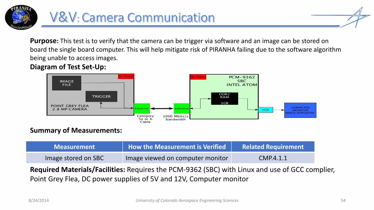
Purpose: This test is to verify that the camera can be trigger via software and an image can be stored on board the single board computer. This will help mitigate risk of PIRANHA failing due to the software algorithm being unable to access images.
Diagram of Test Set-Up:
Summary of Measurements:
Required Materials/Facilities: Requires the PCM-9362 (SBC) with Linux and use of GCC complier, Point Grey Flea, DC power supplies of 5V and 12V, Computer monitor
Measurement How the Measurement is Verified Related Requirement
Image stored on SBC Image viewed on computer monitor CMP.4.1.1

8/24/2014 University of Colorado Aerospace Engineering Sciences 55
Purpose: This test is to verify that a servo can be instructed via software to more to a position and then have the final position returned to the single board computer. This will help mitigate risk of PIRANHA failing due to the software algorithm being unable to point the rangefinder/camera, or read off angle measurements for the relative position vector.
Diagram of Test Set-Up:
Summary of Measurements:
Required Materials/Facilities: Requires the PCM-9362 (SBC) with Linux and use of GCC complier, MX-64 Servo, DC power supplies of 5V and 12V, Computer monitor
Measurement How the Measurement is Verified Related Requirement
Send and receive data from servo Compare output position from servo to command position

Purpose: Verify the camera operates with the FOV and pixel count specified in data sheet. Test will mitigate the possibility of failure due to defective camera, or the incorrect FOV and pixel count entered into software algorithms
Diagram:
8/24/2014 University of Colorado Aerospace Engineering Sciences 56
Image Processing Software for pixel
count
Known distance
Mea
sure
d d
ista
nce
to
ca
lcu
late
FO
V
Verify pixels and FOV

Summary of Measurements:
Required Materials/Facilities: • Wall
• PointGrey Flea 3.0
• Image Processing Software
8/24/2014 University of Colorado Aerospace Engineering Sciences 57
Measurement How the Measurement is Verified
Expected Result Related Requirement
Pixels Pixel count DES.2.1, DES.3.1
FOV (deg) Distance for field of view known at 20 meters
Depends on Lens DES.2.1, DES.3.1

8/24/2014 University of Colorado Aerospace Engineering Sciences 58
Purpose: Verify that the control law, when connected with the camera, centers an object in the field of view in the manner stated by project requirements. The test will also help in mitigating the risk of PIRANHA failing due to inability of the debris to be ranged.
Object in FOV not Centered
Control Law Commands
Servos
Compare
Measurement How the Measurement is
Verified
Expected Accuracy
Related Requirement
Calculated Centroid offset from Field of View Center
Comparison with control law
software test
± 0.14˚ maximum
CMP.2.1.1.1 CMP.4.2.1.1
Summary of Measurements:
Diagram
Required Materials/Facilities: • Camera gimbal assembled according to design
• Servos, camera, rangefinder attached • Single Board Computer • Communication cables (USB and RS-485) • 2 white spheres, 10 and 40 cm in diameter • Black Sheet
Comparison of Object Position in FOV with Ideal
Servos Reposition
Camera
Object Moves in FOV
Center of FOV
FOV FOV

8/24/2014 University of Colorado Aerospace Engineering Sciences 59
Purpose: Verify that in a capture-like scenario, PIRANHA is capable of tracking, ranging
characterizing debris, and outputs quaternion and ephemeris data in a form acceptable by the SOSC. The test will also verify that all hardware and software is interfacing correctly, and will help in mitigating risk of failure associated with running all software and hardware concurrently.
Diagram: Camera sees where debris is
on the table
Fishing Line to Move Debris
PIRANHA
Debris Size Characterization
Quaternion/Ephemeris Compared to required format
Table
Debris less than 1 meters verified to begin the DCS turn

8/24/2014 University of Colorado Aerospace Engineering Sciences 60
Summary of Measurements:
Required Materials/Facilities: • Table with minimum dimensions 2x1 [m] • Paper on which to create position reference for debris, or graph paper • Secondary camera (808 # 16 camera already available, or cell phone) • Timer with visible digits • PIRANHA • Sphere to simulate debris, 10-40 cm • Fishing Line
Measurement How the Measurement is Verified
Expected Accuracy Related Requirement
Relative Position Vector Known Relative Position via Camera and Table Markings
+/- 3 mm (AR1000 Data Sheet), pointing within 0.14 degrees
FNC.4, DES.4.1, CMP.4.2.1.1
Relative distance at which Quaternion Output Changes
Known Relative Distance via Camera and Table Markings
+/- 3mm DES.4.2
Ephemeris and Quaternion Format and Rate
SOSC Known Requirements Identical FNC.5, DES.5.1
Debris Characterization Simulated Debris Measurement
Reflects Test Case Ball Size CMP3.1.1.1, DES.3.2