manufacture of two-layer castings using fe base heat
TRANSCRIPT

ADVANCES IN MANUFACTURING SCIENCE AND TECHNOLOGY
Vol. 42, No. 1-4, 2018 DOI: 10.2478/amst-2018-0003
Address: Prof. Jan SIENIAWSKI, Grzegorz RZEPKA, MSc Eng., Jacek NAWROCKI, PhD Eng., Rzeszow University of Technology, Faculty of Mechanical Engineering and Aeronautics, Department of Materials Science, Żwirki i Wigury 4, 35-959 Rzeszów, e-mail: [email protected], [email protected]
MANUFACTURE OF TWO-LAYER CASTINGS USING Fe BASE HEAT-RESISTANT ALLOYS
Grzegorz Rzepka, Jacek Nawrocki Jan Sieniawski
S u m m a r y
The main purpose of the present study is to verify the possibility of joining grey iron EN-GJL-250 with heat resistant ductile iron GJS-XSiMo5-1 and heat resistant cast steel GX40CrNiSiNb25-20 to create the two-layered material using casting process with materials in liquid state and in solid state. The mentioned above method was assumed to solve in an economically justified manner the problem of defects on turbocharger’s housing which occurred in some high performance premium application. Evaluation of joint quality was investigated by microstructure observation (LM), alloy elements diffusion (SEM), hardness measurement and discontinuity inspection by computed tomography scanning (CT).
Keywords: grey cast iron, heat resistant ductile iron, heat resistant cast steel, two-layered material, intermediate zone, casting
Wytwarzanie odlewów dwuwarstwowych z zastosowaniem stopów żaroodpornych
na osnowie Fe z mikrostrukturą typu ferryt i austenit
S t r e s z c z e n i e
W pracy przedstawiono rezultaty badań określających stopień możliwości wytworzenia połączenia żeliwo szare EN-GJL-250 – żaroodporne żeliwo sferoidalne GJS-XSiMo5-1 lub żaroodporne staliwo GX40CrNiSiNb25-20 w procesie odlewania – materiał w stanie ciekłym i materiał w stanie stałym. Analiza uzyskanych wyników badań wskazuje, że zaproponowana metoda jest ekonomicznie uzasadniona dla rozwiązania występujących wad w obudowie turbosprężarki pojawiających się podczas pracy w warunkach dużej wydajności. Ocenę jakości połączenia prowadzono w badaniach mikrostruktury połączenia (LM i SEM), pomiarach twardości i kontroli nieciągłości przy użyciu tomografii komputero- wej (CT).
Słowa kluczowe: żeliwo szare, żaroodporne żeliwo sferoidalne, żaroodporne staliwo, materiał dwu- warstwowy, warstwa przejściowa, odlewanie
1. Introduction
Nowadays the higher and higher power output and performance are requested for the premium passenger car engines. The turbochargers are commonly used to increase engine power with less fuel consumption, relatively. One of the ways to

32 G. Rzepka, J. Nawrocki, J. Sieniawski
achieve this aim is increasing the temperature at the inlet into the turbocharger, even up to 1050 °C for the gasoline applications. Due to this fact, the heat flux to the bearing housing significantly grows also (Fig.1). Grey cast iron EN-GJL-250 is widely used as the material of bearing housing of turbocharger. It has some important benefits like good castability, machinability, corrosion resistance, filling mould. It is also characterized by high damping capacity, low melting point and relatively low cost [1]. When this grey cast iron is used to manufacture casting bearing housing, some breakages placed in flange of bearing housing could occur (Fig. 2). Relatively small resistance to thermal stresses of this material (190 MPa in 500 °C) is reason of defect formation in very high performance turbochargers.
Fig. 1. Cross-section of turbocharger: a – bearing housing; b – turbine stage, c – area of defects on bearing housing
Fig. 2. Breakage of the flange of bearing housing

Manufacture of two-layer castings using... 33
It can be assumed that simplest solution to prevent casting from breakages in the case described above could be using the higher grade material – like heat resistant ductile iron or heat resistant cast steel. Mentioned solution is not optimal from the economical point of view. New, more expensive material required to perform validation procedure to examine the behavior of the bearing components and oil in the contact with new material. Validation tests procedure is very high costly also. Consider this, the assumption that allows to apply higher grade material only locally, in areas where it is necessary was made. Assumption can be realized by providing two-layered material, consisting of the grey cast iron EN-GJL-250 in the bearing housing area and new, more heat resistant material in the housing flange area – where the heat flux from turbine stage of turbocharger is increased.
Two-layered material can be manufactured using several methods. Commonly used method is welding process [2]. Although the process is well-known, it is quite expensive in mass production, simple surface of joint is required and cracks are common at the weld interface. Another method which is similar to welding, also regarding restrictions, is vacuum brazing [3]. Additionally, it requires precisely machined surfaces for the joint. So called hot diffusion-compression bonding method can be also used to produce the two-layered materials [4]. In this process two materials in solid state are compressed in high temperature to allow the creation of the bond. This method is restricted to small components with simple shapes. The preparation of the surface for the joint is necessary. The next wide group of methods to produce two-layered material is casting. There are two main types of this process. First one is using two liquid alloys (liquid-liquid), which are poured into casting mould one after another [5-7] or simultaneously in vertical direction without mixing of input materials [8]. The benefit of this method is that there is no need to prepare the surface for joint, but the mould is complicated, there is need to control temperature of process (using thermocouples) and surface of the joint has to be plain (gravitationally required). The second type of casting method is using one of the materials in solid state, placing it in the form and pouring on it the second material in liquid state (solid-liquid)[9-14]. This process allows to provide complex surface of the joint (as the shape of the material in solid state). Modification of the described above process is using the material in state of the powder, which is placed in the mould and then poured with liquid material [2, 15-16].
From the economical point of view, best solution to resolve the problem discussed is solid-liquid process. To substantial increase of heat resistance, ductile iron GJS-XSiMo5-1 and cast steel GX40CrNiSiNb25-20 have been selected. The review of literature indicate that limited information considering joining of materials EN-GJL-250/GJS-XSiMo5-1 and EN-GJL-250/GX40CrNiSiNb25-20 are available. The focus of scientific literature is on joining grey cast iron to different types of cast steel and cast iron dedicated to work in low/ambient temperature [5, 7, 9, 17-21]. Literature data suggest that good quality joining of
34 G. Rzepka, J. Nawrocki, J. Sieniawski
materials from group Fe-C is determined if significant difference of carbon content (∆C) between joined materials occurs. Depending on the different casting parameters, value of difference vary from 1,0 to 2,0 wt.% [21]. As far as this requirement is achieved for materials GJL-250/GX40CrNiSiNb25-20 (∆C: from 2,5 to 2,9 wt.%), though no requirement for materials GJL-250/GJS-XSiMo5-1 (∆C: from 0,0 to 2,6 wt.%) is fulfilled.
The main objective of present study is to determine the possibility of joining grey iron EN-GJL-250 with ductile iron GJS-XSiMo5-1 and cast steel GX40CrNiSiNb25-20. Evaluation of joint quality was investigated by microstructure observation (LM), alloy elements diffusion (SEM), hardness measurement and discontinuity inspection by computed tomography scanning (CT).
2. Material and experiment
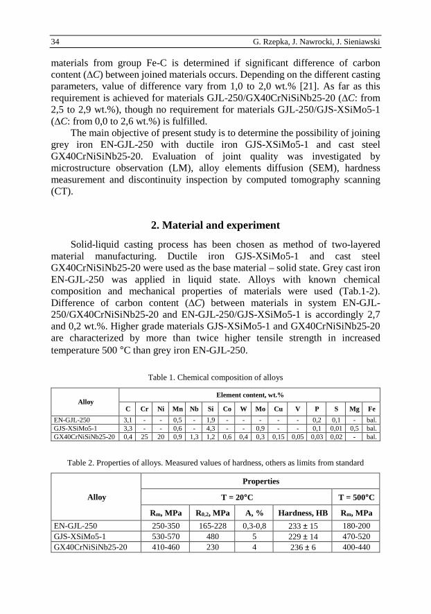
Solid-liquid casting process has been chosen as method of two-layered material manufacturing. Ductile iron GJS-XSiMo5-1 and cast steel GX40CrNiSiNb25-20 were used as the base material – solid state. Grey cast iron EN-GJL-250 was applied in liquid state. Alloys with known chemical composition and mechanical properties of materials were used (Tab.1-2). Difference of carbon content (∆C) between materials in system EN-GJL-250/GX40CrNiSiNb25-20 and EN-GJL-250/GJS-XSiMo5-1 is accordingly 2,7 and 0,2 wt.%. Higher grade materials GJS-XSiMo5-1 and GX40CrNiSiNb25-20 are characterized by more than twice higher tensile strength in increased temperature 500 °C than grey iron EN-GJL-250.
Table 1. Chemical composition of alloys
Alloy Element content, wt.%
C Cr Ni Mn Nb Si Co W Mo Cu V P S Mg Fe
EN-GJL-250 3,1 - - 0,5 - 1,9 - - - - - 0,2 0,1 - bal. GJS-XSiMo5-1 3,3 - - 0,6 - 4,3 - - 0,9 - - 0,1 0,01 0,5 bal. GX40CrNiSiNb25-20 0,4 25 20 0,9 1,3 1,2 0,6 0,4 0,3 0,15 0,05 0,03 0,02 - bal.
Table 2. Properties of alloys. Measured values of hardness, others as limits from standard
Alloy
Properties
T = 20°C T = 500°C
Rm, MPa R0,2, MPa A, % Hardness, HB Rm, MPa
EN-GJL-250 250-350 165-228 0,3-0,8 233 ± 15 180-200 GJS-XSiMo5-1 530-570 480 5 229 ± 14 470-520 GX40CrNiSiNb25-20 410-460 230 4 236 ± 6 400-440

Manufacture of two-layer castings using... 35
Specimens were manufactured as “sandwich” consisted of two rounded slices of materials (Fig. 3). Volume of base material (b) was around two times bigger than melted material (a). Specimens surface were prepared by dry sandblasting, then ultrasonic washed in isopropyl alcohol and dried. As heat source, electric arc in vacuum welding machine Arc Melter AM was used. Current value from 150 to 170 A was applied, until upper material was re-melted.
Fig. 3. Scheme of the specimen: a – material in liquid state (EN-GJL-250), b – base material in solid state (GJS-XSiMo5-1 or GX40CrNiSiNb25-20)
Cross section of both joined material systems were prepared using standard metallographic mechanical grinding and polishing techniques. Light microscopy (LM) observations were performed using Leica DM3000 microscope. Scanning electron microscopy (SEM/EDS) observations conducted using Hitachi S-3400N microscope. Hardness was measured using the Vickers method, but the results were converted according to ISO 18265 to Brinell method scale HB, which is used widely in automotive industry. Quality of the joint was evaluated in three dimensional space (3D) using computed tomography (CT) scanning. Nikon XT H450 system with rotating cathode lamp was used with lamp power of 48,06 W and resolution of 16 µm.
3. Results and discussion
Typical microstructure of the input materials – ferrite with flakes graphite of grey cast iron, dendritic austenite of heat resistant cast steel and ferrite with spheroidal graphite of heat resistant ductile iron is shown on Fig. 4.
Microstructure morphology of joint zone in examined system EN-GJL-250/GJS-XSiMo5-1 demonstrate sharp transition (Fig. 5a). Ferrite with spheroidal graphite of GJS-XSiMo5-1 rapidly changes into pearlite microstructure with visible separations of graphite. Observed microstructure transition of EN-GJL-250 iron is the consequence of carbon diffusion caused by heat impact during melting process. Furthermore, both form of graphite – flake and nodule are subject of degradation in the joint zone (Fig. 5b). Whole graphite flakes transform to “jagged” shape – temper carbon. Some of the graphite nodules in heat affected zone (HAZ) present inconsiderable decomposition of spheroidal shape to more “jagged” shape also.

36 G. Rzepka, J. Nawrocki, J. Sieniawski
a) b) c)
Fig. 4. Microstructure of the input materials: a) EN-GJL-250, b) GJS-XSiMo5-1,
c) GX40CrNiSiNb25-20
Fig. 5. Microstructure of the joint zone in system EN-GJL-250(1)/GJS-XSiMo5-1(2)
In contrast to system grey iron – ductile iron, joint zone in system EN-GJL-250/GX40CrNiSiNb25-20 demonstrate presence of intermediate zone (Fig. 6a). Zone area corresponds to HAZ in austenitic matrix of cast steel. Cast steel microstructure transform from coarse to fine grained, dendrites arm spacing is few times less than in material beyond of HAZ (Fig. 6b). It has to be noticed, that the microstructure of grey cast iron EN-GJL-250 transform likewise as in system grey cast iron – ductile iron.
Fig. 6. Microstructure of the joint zone in system EN-GJL-250(1)/GX40CrNiSiNb25-20(2)

Manufacture of two-layer castings using... 37
There is no evidence of alloy elements diffusion between materials in system EN-GJL-250/GJS-XSiMo5-1 (Fig. 7). The reason for lack of elements diffusion is small difference in chemical composition both joined materials. Intermediate zone observed in system EN-GJL-250/GX40CrNiSiNb25-20 is characterized by continuous change of Cr and Ni content (Fig.8). Atoms diffuses from cast steel to iron to the depth around 450 µm. Other elements difference between joined materials is too less to activate atoms diffusion.
Fig. 7. Change of chemical composition in joined system EN-GJL-250(1)/ GJS-XSiMo5-1(2)
Fig. 8. Change of chemical composition in joined system in system EN-GJL-250(1)
/GX40CrNiSiNb25-20(2)
The result of the hardness measurement confirms microstructural transitions in joined materials. In both joined systems microstructure transformation of EN-GJL-250 from ferrite to pearlite results in significant hardness increasing (Fig. 9). Hardness value change from 233 HB up to 600 HB in both experiments. Intermediate zone which is visible on microscope examination in system EN-GJL-250/GX40CrNiSiNb25-20 is reflected by hardness measurement (Fig. 9a). Except of one point which disrupt results (cause of mixing materials in joint zone) continuous change from 600 HB to 200 HB in cast steel is observed. Hardness measurement indicate that intermediate zone is deeper than defined from chemical

38 G. Rzepka, J. Nawrocki, J. Sieniawski
analysis and value is around 1,2 mm. Microscope evaluation of joint in system EN-GJL-250/GJS-XSiMo5-1 did not indicate any intermediate zone presence. Still, hardness measurement result highlighted of this zone occurrence (Fig. 9b). Hardness value vary in zone from 300 HB to 400 HB and depth of zone is around 2,4 mm.
a) b)
Fig. 9. Hardness profile in joined systems with intermediate zones (3) and (6): a) EN-GJL-250(1)
/GX40CrNiSiNb25-20(2), b) EN-GJL-250(4)/GJS-XSiMo5-1(5)
a) b)
Fig. 10. Joint in system EN-GJL-250(1)/GJS-XSiMo5-1(2): a) radiogram (CT), b) microscopic image
a) b)
Fig. 11. Joint in system EN-GJL-250(1)/GX40CrNiSiNb25-20(2): a) radiogram (CT),
b) microscopic image

Manufacture of two-layer castings using... 39
In effect of 3D computed tomography examination of joined systems, no discontinuity and porosity in both cases was detected (Fig. 10, 11).
4. Summary and conclusions
1. The results obtained in present work reinforces potential use of cast steel GX40CrNiSiNb25-20 and ductile iron GJS-XSiMo5-1 materials to manu- facturing two-layered casting in combination with grey iron EN-GJL-250. Intermediate zone in both experiments is free from discontinuities and porosity. Good quality of joints were confirmed in whole connection surface by (CT) method.
2. In cause of joining materials EN-GJL-250 and GJS-XSiMo5-1, though that condition described in literature regarding carbon content in joined materials was not fulfilled, good quality of joint has been achieved also. It should be pointed out, that arc melting technique was used in experiment to join materials. We can assume, that high temperature of flame enabled joining materials without meet of mentioned condition.
3. In both joined systems of materials intermediate zone is formed. For system EN-GJL-250/GX40CrNiSiNb25-20 zone is visible with microscope technique application. Zone area constitute finer dendritic austenitic microstructure then originally used cast steel. Intermediate zone in system EN-GJL-250/GJS-XSiMo5-1 is not visible under microscope. for system of heat resistant cast steel and grey cast iron. Depth of zones is different and value is respectively around 2,0 and 1,0 mm. No significant change of chemical composition on the transverse cut was observed for the joint between grey cast iron and heat resistant ductile iron, because of the relatively small difference in chemical composition of the joined materials. The continuous change of the content of Cr and Ni was observed in the intermediate zone for the joint between grey cast iron and heat resistant cast steel.
4. Remelt of ferrite microstructure in grey iron EN-GJL-250 results in perlite forming. Graphite flakes are transformed to “jagged” shape – temper carbon. New microstructure is characterized by three times higher hardness than originally used grey iron. We can consider this phenomenon as unfavorable seeing that worse machinability of remelted material.
The work on this problem is in progress and consecutive results will be published in a succeeding paper.
References
[1] C.F. WALTON, T.J. OPAR: Iron Casting Handbook. Iron Casting Society Inc., New York 1981, 57.
[2] J. SZAJNAR, P. WRÓBEL, T. WRÓBEL: Multi-layers castings. Archives of Found Engineering, 10(2010)1, 181-186.

40 G. Rzepka, J. Nawrocki, J. Sieniawski
[3] P. HUGGETT, R. WUHRER, B. BEN-NISSAN, K. MORAN: A novel metallurgical bonding process and microstructural analysis of ferrous alloy composites. Materials Forum, 29(2005), 83-88.
[4] X. GAO, Z. JIANG, D. WEI, S. JIAO, D. CHEN, J. XU, X. ZHANG, D. GONG: Effects of temperature and strain rate on microstructure and mechanical properties of high chromium cast iron / low carbon steel bimetal prepared by hot diffusion-compresion bonding. Materials and Design, 63(2014), 650-657.
[5] T. KIRMA: Production of coal-crusher hammer heads by bi-metal casting. Master of Science Thesis of Middle East Technical University. Ankara 2008.
[6] S. ZIC, I. DZAMBAS, M. KONIĆ: Possibilities of implementing bimetallic hammer castings in crushing industries. Metalurgija, 48(2009)1, 51-54.
[7] F. BINCZYK, J. SITKO, E. CZERWIŃSKI, E. KRZEMIEŃ: Krystalizacja żeliwa szarego i stopowego na walce dwuwarstwowe. Archiwum Odlewnictwa, 1(2001)1, 34-41.
[8] E. MARUKOVICH, A. BRANOVITSKY, Y. NA, J. LEE, K. CHOI: Study on the possibility of continuous-casting of bimetallic components in condition of direct connection of metals in a liquid state. Materials and Design, 27(2006), 1016-1026.
[9] F. CALVO, A. URENA, M. GOMEZ DE SALAZAR, F. MOLLEDA: Difusion bonding of grey cast iron to Armco iron and a carbon steel. Journal of Materials Science Letters, 24(1989), 4152-4159.
[10] T. VIGRAMAN, D. RAVINDRAN, R. NARAYANASAMY: Diffusi on bonding of AISI 304L steel to low-carbon steel with AISI 304L steel interlayer. Materials and Design, 34(2012), 594-602.
[11] P. WRÓBEL, J. SZAJNAR, J. GAWROŃSKI: Kompleksowa ocena warunków powstawania kompozytowej warstwy stopowej na powierzchni odlewu staliwnego. Archiwum Odlewnictwa, 4(2004)14, 593-604.
[12] B. XIONG, C. CAI, B. LU: Effect of volume ratio of liquid to solid on the interfacial microstructure and mechanical properties of high chromium cast iron and medium carbon steel bimetal. Journal of Alloys and Compounds, 509(2011), 6700-6704.
[13] H. SALLAM, K. EL-AZIZ, H. EL-RAOUF, E. ELBANNA: Failure analysis and flexural behavior of high chromium white cast iron and AISI4140 Steel bimetal beams. Material and Design, 52(2013), 974-980.
[14] D. BARTOCHA, J. SUCHOŃ, S. JURA: Odlewy warstwowe. Krzepnięcie Metali i Stopów, 38(1998), 151-156.
[15] T. WRÓBEL: Ni and Cr base layers in bimetallic castings. Proc. 20th Anniversary International Conference on Metallurgy and Materials METAL 2011 Brno, Brno 2011, 758-764.
[16] J. SZAJNAR, T. WRÓBEL, A. DULSKA: Manufacturing Methods of Alloy Layers on Casting Surfaces. Journal of Casting & Materials Engineering, 1(2017)1, 2-6.
[17] S. ERTÜRK, O. ҪAKIR, L. KUMRUOGLU, A. OZEL: Fabricating of steel/cast iron composite by casting route. Acta Physica Polonica A, 125(2013)2, 452-453.
[18] I. KISS, S. MAKSAY: Bimetallic cast iron rolls – some approaches to assure the exploitation properties. Technical Gazette, 17(2010), 173-178.
[19] A. AVCI, N. İLKAYA, M. ŞIMŞIR, A. AKDEMIR: Mechanical and microstructural properties of low-carbon steel-plate-reinforced gray cast iron. Journal of Materials Processing Technology, 209(2009), 1410-1416.

Manufacture of two-layer castings using... 41
[20] M. RAMADAN: Interface characterization of bimetallic casting with a 304 stainless steel surface layer and a gray cast iron base. Advanced Materials Research, 1120-1121(2015), 993-998.
[21] T. WRÓBEL, M. CHOLEWA: The influence of selected cast parameters on quality of joint in layered castings. Archives of Foundry Engineering, 12(2012)2, 105-110.
Received in November 2018

42 G. Rzepka, J. Nawrocki, J. Sieniawski