manual · 2021. 7. 21. · ordercode: 50754/50755/50757 3 ddp-610 mkii important! the manufacturer...
TRANSCRIPT

DDP-610 MKII V1
Highlite International B.V. – Vestastraat 2 – 6468 EX – Kerkrade – the Netherlands
Ordercode: 50754/50755/50757
MANUAL
ENGLISH

1
Ordercode: 50754/50755/50757
DDP-610 MKII
Table of contents
Warning ............................................................................................................................................................................... 2 Safety Instructions ......................................................................................................................................................... 2 Operating Determinations .......................................................................................................................................... 4 Connection with the Single-Phase Power Network ............................................................................................... 4 Connection with the Three-Phase Power Network ................................................................................................ 4 Return Procedure .......................................................................................................................................................... 5 Claims .............................................................................................................................................................................. 5
Description of the device ................................................................................................................................................. 6 Frontside.......................................................................................................................................................................... 6 Backside DDP-610M (ordercode 50754) .................................................................................................................. 7 Backside DDP-610S (ordercode 50755) .................................................................................................................... 7 Backside DDP-610T (ordercode 50757) .................................................................................................................... 8
Installation ........................................................................................................................................................................... 8 Pin assignment DDP-610M (ordercode 50754) ........................................................................................................ 8 Terminal connections DDP-610T (ordercode 50757).............................................................................................. 9 Occupation of the XLR connection (All versions) .................................................................................................. 9 Occupation of the analog connector (DDP-610S ordercode 50755/DDP-610T .............................................. 9 ordercode 50757) ......................................................................................................................................................... 9
Set Up and Operation .....................................................................................................................................................10 Switching power to the DDP-610 MKII .....................................................................................................................10 Manual channel output adjustment .......................................................................................................................10 Menu Overview ...........................................................................................................................................................11 Main Menu Options ....................................................................................................................................................12
1. Patching mode ....................................................................................................................................................12 2. Dimming curve .....................................................................................................................................................13 3. Minimum output level .........................................................................................................................................14 4. Maximum output level ........................................................................................................................................14 5. DMX failure settings .............................................................................................................................................15
Maintenance ....................................................................................................................................................................15
Troubleshooting ...............................................................................................................................................................16
Product Specifications ....................................................................................................................................................16
Dimensions ........................................................................................................................................................................17
Notes ..................................................................................................................................................................................18

2
Ordercode: 50754/50755/50757
DDP-610 MKII
Warning
Unpacking Instructions Immediately upon receiving this product, carefully unpack the carton and check the contents to ensure
that all parts are present, and have been received in good condition. Notify the dealer immediately and
retain packing material for inspection if any parts appear damaged from shipping or the carton itself
shows signs of mishandling. Save the carton and all packing materials. In the event that a fixture must be
returned to the factory, it is important that the fixture be returned in the original factory box and packing.
Your shipment includes: Showtec DDP-610 MKII
User manual
Safety Instructions Every person involved with the installation, operation and maintenance of this device has to:
be qualified
follow the instructions of this manual
Before your initial start-up, please make sure that there is no damage caused by transportation. Should
there be any, consult your dealer and do not use the device.
To maintain perfect condition and to ensure a safe operation, it is absolutely necessary for the user to
follow the safety instructions and warning notes written in this manual.
Please consider that damages caused by manual modifications to the device are not subject to
warranty.
This device contains no user-serviceable parts. Refer servicing to qualified technicians only.
3
Ordercode: 50754/50755/50757
DDP-610 MKII
IMPORTANT! The manufacturer will not accept liability for any resulting damages caused by the non-observance of
this manual or any unauthorized modification to the device.
Never let the power cord come into contact with other cables! Handle the power cord and all
connections with the mains with particular caution!
Never remove warning or informative labels from the unit.
Do not insert objects into air vents.
Do not open the device and do not modify the device.
Do not connect this device to another dimmerpack.
Do not switch the device on and off in short intervals, as this would reduce the system’s life.
Only use device indoor, avoid contact with water or other liquids.
Avoid flames and do not put close to flammable liquids or gases.
Always disconnect power from the mains, when device is not used or before cleaning! Only handle
the power cord by the plug. Never pull out the plug by tugging the power cord.
Make sure that the available voltage is not higher than stated on the rear panel.
Make sure that the power cord is never crimped or damaged. Check the device and the power
cord from time to time.
If device is dropped or struck, disconnect mains power supply immediately. Have a qualified
engineer inspect for safety before operating.
If the device has been exposed to drastic temperature fluctuation (e.g. after transportation), do not
switch it on immediately. The arising condensation water might damage your device. Leave the
device switched off until it has reached room temperature.
If your Showtec device fails to work properly, discontinue use immediately. Pack the unit securely
(preferably in the original packing material), and return it to your Showtec dealer for service.
For replacement use fuses of same type and rating only.
This device falls under protection class I. Therefore it is essential to connect the yellow/green
conductor to earth.
Repairs, servicing and electric connection must be carried out by a qualified technician.
WARRANTY: Till one year after date of purchase.

4
Ordercode: 50754/50755/50757
DDP-610 MKII
Operating Determinations This device is not designed for permanent operation. Consistent operation breaks will ensure that the
device will serve you for a long time without defects.
The maximum ambient temperature ta = 40°C must never be exceeded.
The relative humidity must not exceed 50 % with an ambient temperature of 40° C.
If this device is operated in any other way, than the one described in this manual, the product may
suffer damages and the warranty becomes void.
Any other operation may lead to dangers like short-circuit, burns, electric shock, crash etc.
You endanger your own safety and the safety of others!
Connection with the Single-Phase Power Network Connect the device to the mains with the power-plug.
Always make sure, that the right color cable is connected to the right place.
International EU Cable UK Cable US Cable Pin L BROWN RED YELLOW/COPPER PHASE
N BLUE BLACK SILVER NEUTRAL
YELLOW/GREEN GREEN GREEN PROTECTIVE
GROUND
Connection with the Three-Phase Power Network Connect the device to the 3-phase Power Socket with a CEE-form power-plug.
Always make sure that the right color cable is connected to the right place.
International EU Cable UK Cable US Cable Pin L1 BROWN RED BLACK PHASE 1
L2 BLACK YELLOW RED PHASE 2
L3 GREY BLUE BLUE PHASE 3 N BLUE BLACK WHITE NEUTRAL
YELLOW/GREEN GREEN GREEN PROTECTIVE GROUND
Make sure that the device is always connected properly to the earth!
Improper installation can cause serious injuries to people and/or damage of property !

5
Ordercode: 50754/50755/50757
DDP-610 MKII
Return Procedure Returned merchandise must be sent prepaid and in the original packing, call tags will not be issued.
Package must be clearly labeled with a Return Authorization Number (RMA number). Products returned
without an RMA number will be refused. Highlite will not accept the returned goods or any responsibility.
Call Highlite 0031-455667723 or mail [email protected] and request an RMA prior to shipping the fixture.
Be prepared to provide the model number, serial number and a brief description of the cause for the
return. Be sure to properly pack fixture, any shipping damage resulting from inadequate packaging is the
customer’s responsibility. Highlite reserves the right to use its own discretion to repair or replace
product(s). As a suggestion, proper UPS packing or double-boxing is always a safe method to use.
Note: If you are given an RMA number, please include the following information on a piece of paper
inside the box:
01) Your name
02) Your address
03) Your phone number
04) A brief description of the symptoms
Claims The client has the obligation to check the delivered goods immediately upon delivery for any short-
comings and/or visible defects, or perform this check after our announcement that the goods are at their
disposal. Damage incurred in shipping is the responsibility of the shipper; therefore the damage must be
reported to the carrier upon receipt of merchandise.
It is the customer's responsibility to notify and submit claims with the shipper in the event that a fixture is
damaged due to shipping. Transportation damage has to be reported to us within one day after receipt
of the delivery.
Any return shipment has to be made post-paid at all times. Return shipments must be accompanied with
a letter defining the reason for return shipment. Non-prepaid return shipments will be refused, unless
otherwise agreed in writing.
Complaints against us must be made known in writing or by fax within 10 working days after receipt of the
invoice. After this period complaints will not be handled anymore.
Complaints will only then be considered if the client has so far complied with all parts of the agreement,
regardless of the agreement of which the obligation is resulting.
6
Ordercode: 50754/50755/50757
DDP-610 MKII
Description of the device
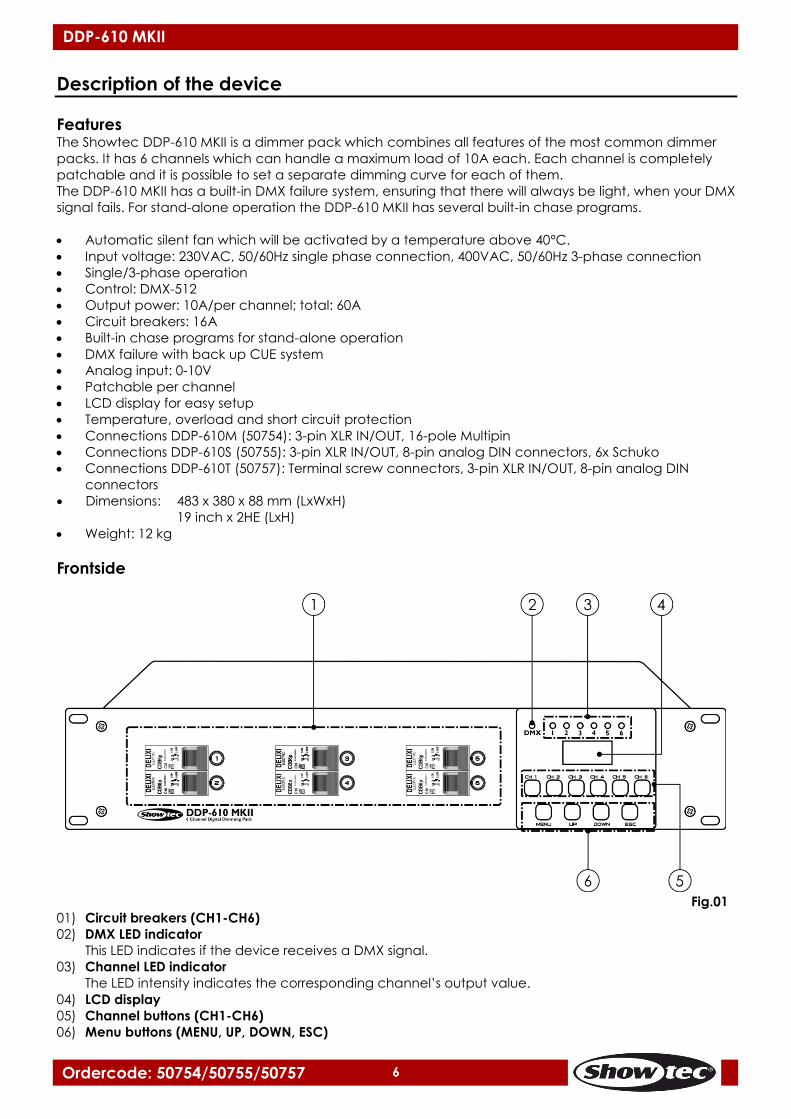
Features The Showtec DDP-610 MKII is a dimmer pack which combines all features of the most common dimmer
packs. It has 6 channels which can handle a maximum load of 10A each. Each channel is completely
patchable and it is possible to set a separate dimming curve for each of them.
The DDP-610 MKII has a built-in DMX failure system, ensuring that there will always be light, when your DMX
signal fails. For stand-alone operation the DDP-610 MKII has several built-in chase programs.
Automatic silent fan which will be activated by a temperature above 40ºC.
Input voltage: 230VAC, 50/60Hz single phase connection, 400VAC, 50/60Hz 3-phase connection
Single/3-phase operation
Control: DMX-512
Output power: 10A/per channel; total: 60A
Circuit breakers: 16A
Built-in chase programs for stand-alone operation
DMX failure with back up CUE system
Analog input: 0-10V
Patchable per channel
LCD display for easy setup
Temperature, overload and short circuit protection
Connections DDP-610M (50754): 3-pin XLR IN/OUT, 16-pole Multipin
Connections DDP-610S (50755): 3-pin XLR IN/OUT, 8-pin analog DIN connectors, 6x Schuko
Connections DDP-610T (50757): Terminal screw connectors, 3-pin XLR IN/OUT, 8-pin analog DIN
connectors
Dimensions: 483 x 380 x 88 mm (LxWxH)
19 inch x 2HE (LxH)
Weight: 12 kg
Frontside
Fig.01
01) Circuit breakers (CH1-CH6)
02) DMX LED indicator
This LED indicates if the device receives a DMX signal.
03) Channel LED indicator
The LED intensity indicates the corresponding channel’s output value.
04) LCD display
05) Channel buttons (CH1-CH6)
06) Menu buttons (MENU, UP, DOWN, ESC)

7
Ordercode: 50754/50755/50757
DDP-610 MKII
Backside DDP-610M (ordercode 50754)
Fig. 02
07) 3-pin DMX signal connector OUT
08) 3-pin DMX signal connector IN
09) Multiconnector output (6 outputs)
Maximum load 10A per output.
10) Power input
Total load should not exceed 32A per phase.
Backside DDP-610S (ordercode 50755)
Fig. 03
11) 3-pin DMX signal connector IN
12) Analog IN 1-6 connector
This connector allows you to control each channel with an analog DC voltage between 0-10V.
13) Analog through 1-6 connector
This connector is wired parallel with the analog input 1-6 connector (12).
14) 3-pin DMX signal connector OUT
15) 6x Schuko output
Maximum load 10A per output.
16) Schuko Power cable
8
Ordercode: 50754/50755/50757
DDP-610 MKII
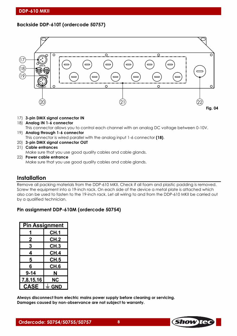
Backside DDP-610T (ordercode 50757)
Fig. 04
17) 3-pin DMX signal connector IN
18) Analog IN 1-6 connector
This connector allows you to control each channel with an analog DC voltage between 0-10V.
19) Analog through 1-6 connector
This connector is wired parallel with the analog input 1-6 connector (18).
20) 3-pin DMX signal connector OUT
21) Cable entrances
Make sure that you use good quality cables and cable glands.
22) Power cable entrance
Make sure that you use good quality cables and cable glands.
Installation Remove all packing materials from the DDP-610 MKII. Check if all foam and plastic padding is removed.
Screw the equipment into a 19-inch rack. On each side of the device a metal plate is attached which
also can be used to fasten to the 19-inch rack. Let all wiring to and from the DDP-610 MKII be carried out
by a qualified technician.
Pin assignment DDP-610M (ordercode 50754)
Always disconnect from electric mains power supply before cleaning or servicing.
Damages caused by non-observance are not subject to warranty.

9
Ordercode: 50754/50755/50757
DDP-610 MKII
Terminal connections DDP-610T (ordercode 50757)
Always disconnect from electric mains power supply before cleaning or servicing.
Damages caused by non-observance are not subject to warranty.
Occupation of the XLR connection (All versions)
Occupation of the analog connector (DDP-610S ordercode 50755/DDP-610T
ordercode 50757)

10
Ordercode: 50754/50755/50757
DDP-610 MKII
Set Up and Operation Follow the directions below, as they pertain to your preferred operation mode.
Before plugging the unit in, always make sure that the power supply matches the product specification
voltage. Do not attempt to operate a 120V specification product on 230V power, or vice versa.
Connect the device to the main power supply.
Switching power to the DDP-610 MKII
01) When powering the unit on, the starting screen will pop up. The display shows .
02) After approximately 5 seconds, the starting menu will appear:
03) A – shows the actual channel which you are editing or the last edited channel. The output of the
channel is indicated by a bar graph.
04) B – overview of all channels. The output of each channel is indicated by a bar graph.
Manual channel output adjustment 01) While in the main menu, press the CH1-CH6 buttons to choose the channel which you want to edit.
02) Press the ESC button to activate the channel output increase mode.
03) Press and hold down the CH1-CH6 button corresponding to the desired channel and observe how
the output value increases.
04) Press the ESC button again to activate the channel output decrease mode.
05) Press and hold down the CH1-CH6 button corresponding to the desired channel and observe how
the output value decreases.
06) Press the MENU button to open the main menu, in order to change settings.

11
Ordercode: 50754/50755/50757
DDP-610 MKII
Menu Overview

12
Ordercode: 50754/50755/50757
DDP-610 MKII
Main Menu Options
Patching mode
Dimming curve
Minimum output level
Maximum output level
DMX failure settings
1. Patching mode
With this menu you can set whether the DMX address is applied to all channels or just one channel at a
time.
01) While in the main menu, press the UP/DOWN buttons until the display shows .
02) Press the MENU button to open the submenu.
03) Press the UP/DOWN buttons to toggle between the following options:
One starting DMX address for all channels.
Set individual DMX addresses for each of the 6 available channels.
04) When the display shows , press the MENU button to proceed to the settings.
05) Press the UP/DOWN buttons to set the starting address for all 6 channels. The adjustment range is
between 001-512.
06) When the display shows , press the MENU button to proceed to the settings.
07) Press the UP/DOWN buttons to choose the channel you would like to adjust.
08) Press the MENU button to proceed to set the DMX address.
13
Ordercode: 50754/50755/50757
DDP-610 MKII
09) Press the UP/DOWN buttons to assign a separate address to each of the 6 channels. The adjustment
range is between 001-512.
10) Once you have adjusted all the settings, press the ESC button to return to the previous menu.
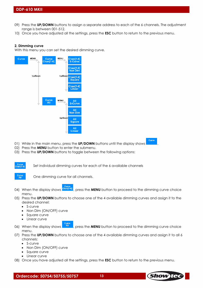
2. Dimming curve
With this menu you can set the desired dimming curve.
01) While in the main menu, press the UP/DOWN buttons until the display shows .
02) Press the MENU button to enter the submenu.
03) Press the UP/DOWN buttons to toggle between the following options:
Set individual dimming curves for each of the 6 available channels
One dimming curve for all channels.
04) When the display shows , press the MENU button to proceed to the dimming curve choice
menu.
05) Press the UP/DOWN buttons to choose one of the 4 available dimming curves and assign it to the
desired channel:
S-curve
Non Dim (ON/OFF) curve
Square curve
Linear curve
06) When the display shows , press the MENU button to proceed to the dimming curve choice
menu.
07) Press the UP/DOWN buttons to choose one of the 4 available dimming curves and assign it to all 6
channels:
S-curve
Non Dim (ON/OFF) curve
Square curve
Linear curve
08) Once you have adjusted all the settings, press the ESC button to return to the previous menu.
14
Ordercode: 50754/50755/50757
DDP-610 MKII
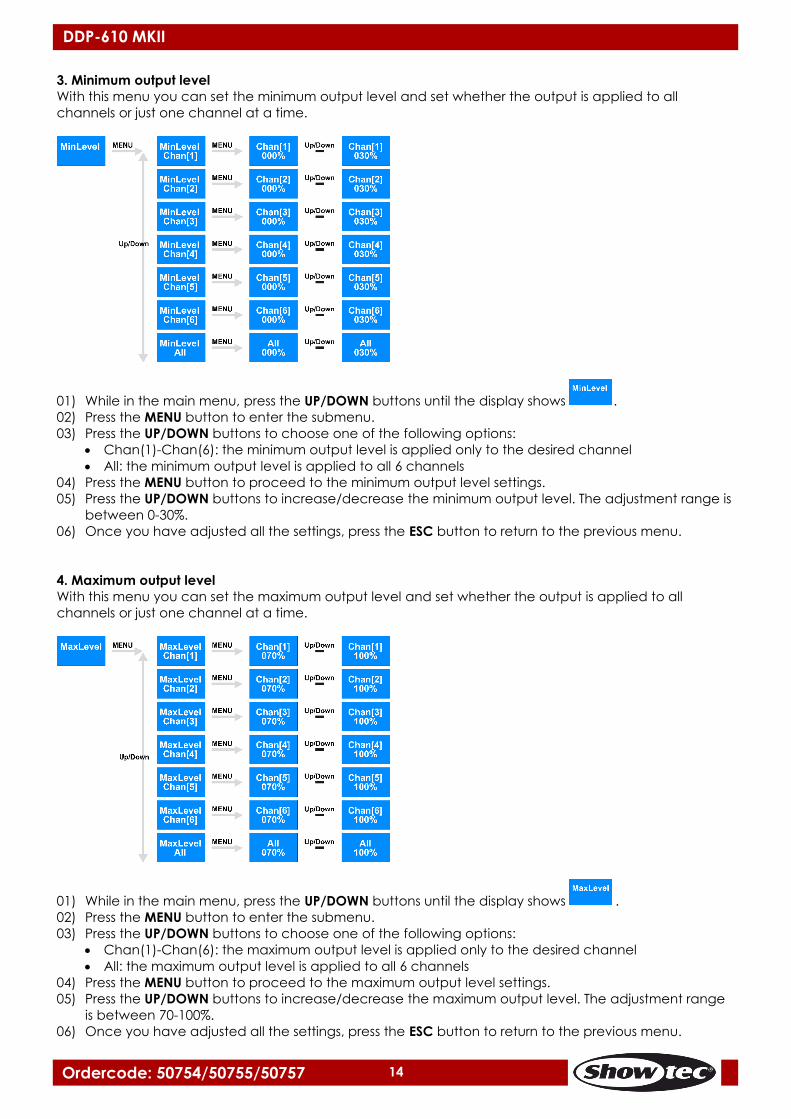
3. Minimum output level
With this menu you can set the minimum output level and set whether the output is applied to all
channels or just one channel at a time.
01) While in the main menu, press the UP/DOWN buttons until the display shows .
02) Press the MENU button to enter the submenu.
03) Press the UP/DOWN buttons to choose one of the following options:
Chan(1)-Chan(6): the minimum output level is applied only to the desired channel
All: the minimum output level is applied to all 6 channels
04) Press the MENU button to proceed to the minimum output level settings.
05) Press the UP/DOWN buttons to increase/decrease the minimum output level. The adjustment range is
between 0-30%.
06) Once you have adjusted all the settings, press the ESC button to return to the previous menu.
4. Maximum output level
With this menu you can set the maximum output level and set whether the output is applied to all
channels or just one channel at a time.
01) While in the main menu, press the UP/DOWN buttons until the display shows .
02) Press the MENU button to enter the submenu.
03) Press the UP/DOWN buttons to choose one of the following options:
Chan(1)-Chan(6): the maximum output level is applied only to the desired channel
All: the maximum output level is applied to all 6 channels
04) Press the MENU button to proceed to the maximum output level settings.
05) Press the UP/DOWN buttons to increase/decrease the maximum output level. The adjustment range
is between 70-100%.
06) Once you have adjusted all the settings, press the ESC button to return to the previous menu.
15
Ordercode: 50754/50755/50757
DDP-610 MKII
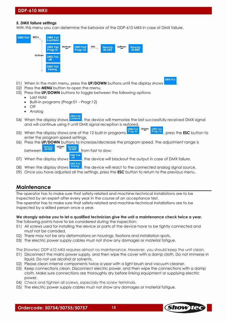
5. DMX failure settings
With this menu you can determine the behavior of the DDP-610 MKII in case of DMX failure.
01) When in the main menu, press the UP/DOWN buttons until the display shows .
02) Press the MENU button to open the menu.
03) Press the UP/DOWN buttons to toggle between the following options:
Last Hold
Built-in programs (Progr:01 - Progr:12)
Off
Analog
04) When the display shows , the device will memorize the last successfully received DMX signal
and will continue using it until DMX signal reception is restored.
05) When the display shows one of the 12 built-in programs , press the ESC button to
enter the program speed settings.
06) Press the UP/DOWN buttons to increase/decrease the program speed. The adjustment range is
between , from fast to slow.
07) When the display shows , the device will blackout the output in case of DMX failure.
08) When the display shows , the device will react to the connected analog signal source.
09) Once you have adjusted all the settings, press the ESC button to return to the previous menu.
Maintenance The operator has to make sure that safety-related and machine-technical installations are to be
inspected by an expert after every year in the course of an acceptance test.
The operator has to make sure that safety-related and machine-technical installations are to be
inspected by a skilled person once a year.
We strongly advise you to let a qualified technician give the unit a maintenance check twice a year.
The following points have to be considered during the inspection:
01) All screws used for installing the device or parts of the device have to be tightly connected and
must not be corroded.
02) There may not be any deformations on housings, fixations and installation spots.
03) The electric power supply cables must not show any damages or material fatigue.
The Showtec DDP-610 MKII requires almost no maintenance. However, you should keep the unit clean.
01) Disconnect the mains power supply, and then wipe the cover with a damp cloth. Do not immerse in
liquid. Do not use alcohol or solvents.
02) Please clean internal components twice a year with a light brush and vacuum cleaner.
03) Keep connections clean. Disconnect electric power, and then wipe the connections with a damp
cloth. Make sure connections are thoroughly dry before linking equipment or supplying electric
power.
04) Check and tighten all screws, especially the screw terminals.
05) The electric power supply cables must not show any damages or material fatigue.
16
Ordercode: 50754/50755/50757
DDP-610 MKII
Troubleshooting This troubleshooting guide is meant to help solve simple problems. If a problem occurs, carry out the steps
below in sequence until a solution is found. Once the unit operates properly, do not carry out the
following steps.
01) If the device does not operate properly, unplug the device.
02) Check power from the wall, all cables, the settings (return to default), etc.
03) Plug the unit in again.
04) If nothing happens after 30 seconds, unplug the device.
05) Return the device to your Showtec dealer.
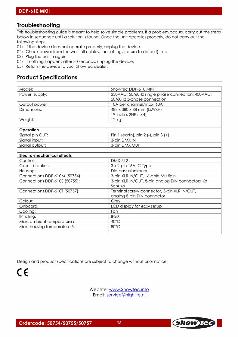
Product Specifications
Model: Showtec DDP-610 MKII
Power supply: 230VAC, 50/60Hz single phase connection, 400VAC,
50/60Hz 3-phase connection
Output power 10A per channel/max. 60A
Dimensions: 483 x 380 x 88 mm (LxWxH)
19 inch x 2HE (LxH)
Weight: 12 kg
Operation
Signal pin OUT: Pin 1 (earth), pin 2 (-), pin 3 (+)
Signal input: 3-pin DMX IN
Signal output: 3-pin DMX OUT
Electro-mechanical effects
Control: DMX-512
Circuit breaker: 3 x 2-pin 16A, C-Type
Housing: Die-cast aluminum
Connections DDP-610M (50754): 3-pin XLR IN/OUT, 16-pole Multipin
Connections DDP-610S (50755): 3-pin XLR IN/OUT, 8-pin analog DIN connectors, 6x
Schuko
Connections DDP-610T (50757): Terminal screw connector, 3-pin XLR IN/OUT,
analog 8-pin DIN connector
Colour: Grey
Onboard: LCD display for easy setup
Cooling: Fan
IP rating: IP20
Max. ambient temperature ta: 40°C
Max. housing temperature tB: 80°C
Design and product specifications are subject to change without prior notice.
Website: www.Showtec.info
Email: [email protected]

17
Ordercode: 50754/50755/50757
DDP-610 MKII
Dimensions

18
Ordercode: 50754/50755/50757
DDP-610 MKII
Notes

©2017 Showtec