managing site-to-site vpns: the basics · an ipsec policy is a set of parameters that define the...
TRANSCRIPT

OL-23991-01
C H A P T E R 21
Managing Site-to-Site VPNs: The BasicsA virtual private network (VPN) consists of multiple remote peers transmitting private data securely to one another over an unsecured network, such as the Internet. Site-to-site VPNs use tunnels to encapsulate data packets within normal IP packets for forwarding over IP-based networks, using encryption to ensure privacy and authentication to ensure integrity of data.
In Cisco Security Manager, site-to-site VPNs are implemented based on IPsec policies that are assigned to VPN topologies. An IPsec policy is a set of parameters that define the characteristics of the site-to-site VPN, such as the security protocols and algorithms that will be used to secure traffic in an IPsec tunnel. Security Manager translates IPsec policies into CLI commands that can be deployed to the devices in the VPN topology. Several policy types might be required to define a full configuration image that can be assigned to a VPN topology, depending on the IPsec technology type.
The Site-to-Site VPN Manager defines and configures site-to-site VPN topologies and policies on Cisco IOS security routers, PIX Firewalls, Catalyst VPN Service Modules, and Adaptive Security Appliance (ASA) firewall devices.
Tip In ASA documentation, site-to-site VPNs are called LAN-to-LAN VPNs. These phrases are equivalent, and we use “site-to-site VPN” in this documentation.
You can access the Site-to-Site VPN Manager by selecting Manage > Site-To-Site VPNs or clicking the Site-To-Site VPN Manager button on the toolbar.
You can also configure shared policies in Policy view and view and configure topologies in Device view. In Policy View, you can assign IPsec policies to VPN topologies.
This chapter contains the following topics:
• Understanding VPN Topologies, page 21-2
• Understanding IPsec Technologies and Policies, page 21-5
• Accessing Site-to-Site VPN Topologies and Policies, page 21-17
• Site-To-Site VPN Discovery, page 21-19
• Creating or Editing VPN Topologies, page 21-28
• Creating or Editing Extranet VPNs, page 21-62
• Deleting a VPN Topology, page 21-66
21-1User Guide for Cisco Security Manager 4.1

Chapter 21 Managing Site-to-Site VPNs: The BasicsUnderstanding VPN Topologies
Understanding VPN TopologiesA VPN topology specifies the peers and the networks that are part of the VPN and how they connect to one another. After you create a VPN topology, the policies that can be applied to your VPN topology become available for configuration, depending on the assigned IPsec technology.
Security Manager supports three main types of topologies—hub and spoke, point to point, and full mesh, with which you can create a site-to-site VPN. Not all policies can be applied to all VPN topologies. The policies that can be applied depend on the IPsec technology that is assigned to the VPN topology. In addition, the IPsec technology that is assigned to a VPN depends on the topology type. For example, the DMVPN and Easy VPN technologies can only be applied in a hub-and-spoke topology.
For more information, see Understanding IPsec Technologies and Policies, page 21-5.
The following topics describe:
• Hub-and-Spoke VPN Topologies, page 21-2
• Point-to-Point VPN Topologies, page 21-3
• Full Mesh VPN Topologies, page 21-4
• Implicitly Supported Topologies, page 21-5
Hub-and-Spoke VPN Topologies In a hub-and-spoke VPN topology, multiple remote devices (spokes) communicate securely with a central device (hub). A separate, secured tunnel extends between the hub and each individual spoke.
The following illustration shows a typical hub-and-spoke VPN topology.
Figure 21-1 Hub-and-Spoke VPN Topology
This topology usually represents an intranet VPN that connects an enterprise’s main office with branch offices using persistent connections to a third-party network or the Internet. VPNs in a hub-and-spoke topology provide all employees with full access to the enterprise network, regardless of the size, number, or location of its remote operations.
Secure tunnelSecure tunnel
SecuretunnelSecure tunnel
Spoke
Spoke
Spoke
Spoke
Branchoffice
Branchoffice
Hub
Mainoffice
Optionalsecondary hubs
for resilience
1300
52Internet
21-2User Guide for Cisco Security Manager 4.1
OL-23991-01

Chapter 21 Managing Site-to-Site VPNs: The BasicsUnderstanding VPN Topologies
A hub is generally located at an enterprise’s main office. Spoke devices are generally located at an enterprise’s branch offices. In a hub-and-spoke topology, most traffic is initiated by hosts at the spoke site, but some traffic might be initiated from the central site to the spokes.
If the hub in a hub-and-spoke configuration becomes unavailable for any reason, IPsec failover transfers tunnel connections seamlessly to a failover (backup) hub, which is used by all spokes. You can configure multiple failover hubs for a single primary hub.
In a hub-and-spoke VPN topology, all IPsec technology types can be assigned except GET VPN.
Related Topics
• Understanding IPsec Technologies and Policies, page 21-5
• Implicitly Supported Topologies, page 21-5
• Creating or Editing VPN Topologies, page 21-28
• Chapter 22, “Configuring IKE and IPsec Policies”
Point-to-Point VPN TopologiesIn a point-to-point VPN topology, two devices communicate directly with each other, without the option of IPsec failover as in a hub-and-spoke configuration. To establish a point-to-point VPN topology, you specify two endpoints as peer devices. Because either of the two devices can initiate the connection, the assigned IPsec technology type can be only regular IPsec or IPsec/GRE.
In Security Manager, you can configure a special type of regular IPsec point-to-point VPN called an Extranet. An Extranet VPN is a connection between a device in your managed network and an unmanaged device, such as a router in your service provider’s network, a non-Cisco device, or simply a device in your network that is being managed by a different group (that is, one that does not appear in the Security Manager inventory).
The following illustration shows a typical point-to-point VPN topology.
Figure 21-2 Point-to-Point VPN Topology
Related Topics
• Understanding IPsec Technologies and Policies, page 21-5
• Implicitly Supported Topologies, page 21-5
• Creating or Editing VPN Topologies, page 21-28
• Creating or Editing Extranet VPNs, page 21-62
• Chapter 22, “Configuring IKE and IPsec Policies”
Site 2Site 113
0053
Internet
Secure tunnel
21-3User Guide for Cisco Security Manager 4.1
OL-23991-01
Chapter 21 Managing Site-to-Site VPNs: The BasicsUnderstanding VPN Topologies
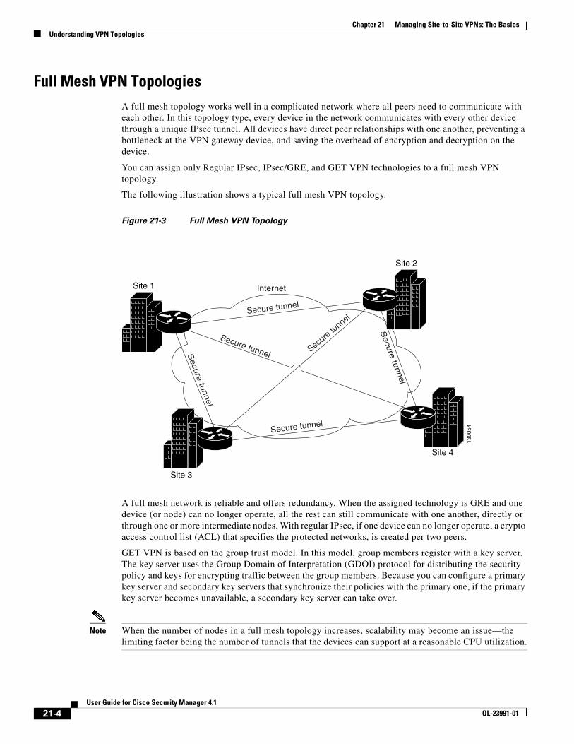
Full Mesh VPN TopologiesA full mesh topology works well in a complicated network where all peers need to communicate with each other. In this topology type, every device in the network communicates with every other device through a unique IPsec tunnel. All devices have direct peer relationships with one another, preventing a bottleneck at the VPN gateway device, and saving the overhead of encryption and decryption on the device.
You can assign only Regular IPsec, IPsec/GRE, and GET VPN technologies to a full mesh VPN topology.
The following illustration shows a typical full mesh VPN topology.
Figure 21-3 Full Mesh VPN Topology
A full mesh network is reliable and offers redundancy. When the assigned technology is GRE and one device (or node) can no longer operate, all the rest can still communicate with one another, directly or through one or more intermediate nodes. With regular IPsec, if one device can no longer operate, a crypto access control list (ACL) that specifies the protected networks, is created per two peers.
GET VPN is based on the group trust model. In this model, group members register with a key server. The key server uses the Group Domain of Interpretation (GDOI) protocol for distributing the security policy and keys for encrypting traffic between the group members. Because you can configure a primary key server and secondary key servers that synchronize their policies with the primary one, if the primary key server becomes unavailable, a secondary key server can take over.
Note When the number of nodes in a full mesh topology increases, scalability may become an issue—the limiting factor being the number of tunnels that the devices can support at a reasonable CPU utilization.
Site 2
Site 1
Site 4
Site 313
0054
Secure
tunnel
Secure tunnelSecu
retu
nnel
Secu
retu
nnel
Secure tunnel
Secure tunnel
Internet
21-4User Guide for Cisco Security Manager 4.1
OL-23991-01
Chapter 21 Managing Site-to-Site VPNs: The BasicsUnderstanding IPsec Technologies and Policies
Related Topics
• Understanding IPsec Technologies and Policies, page 21-5
• Implicitly Supported Topologies, page 21-5
• Creating or Editing VPN Topologies, page 21-28
• Chapter 22, “Configuring IKE and IPsec Policies”
Implicitly Supported TopologiesIn addition to the three main VPN topologies, other more complex topologies can be created as combinations of these topologies. They include:
• Partial mesh—A network in which some devices are organized in a full mesh topology, and other devices form either a hub-and-spoke or a point-to-point connection to some of the fully meshed devices. A partial mesh does not provide the level of redundancy of a full mesh topology, but it is less expensive to implement. Partial mesh topologies are generally used in peripheral networks that connect to a fully meshed backbone.
• Tiered hub-and-spoke—A network of hub-and-spoke topologies in which a device can behave as a hub in one or more topologies and a spoke in other topologies. Traffic is permitted from spoke groups to their most immediate hub.
• Joined hub-and-spoke—A combination of two topologies (hub-and-spoke, point-to-point, or full mesh) that connect to form a point-to-point tunnel. For example, a joined hub-and-spoke topology could comprise two hub-and-spoke topologies, with the hubs acting as peer devices in a point-to-point topology.
Related Topics
• Creating or Editing VPN Topologies, page 21-28
• Hub-and-Spoke VPN Topologies, page 21-2
• Point-to-Point VPN Topologies, page 21-3
• Full Mesh VPN Topologies, page 21-4
Understanding IPsec Technologies and PoliciesSecurity Manager provides seven types of IPsec technologies that you can configure on the devices in your site-to-site VPN topology—Regular IPsec, IPsec/GRE, GRE Dynamic IP, standard and large scale DMVPN, Easy VPN, and GET VPN. The assigned technology determines which policies you can configure for the VPN.
You assign an IPsec technology to a VPN topology during its creation. After an IPsec technology is assigned to a VPN topology, you cannot change the technology, other than by deleting the VPN topology and creating a new one. See Defining the Name and IPsec Technology of a VPN Topology, page 21-30.
The following topics explain some basic concepts about IPsec technologies and site-to-site VPN policies:
• Understanding Mandatory and Optional Policies for Site-to-Site VPNs, page 21-6
• Overview of Site-to-Site VPN Policies, page 21-8
• Understanding Devices Supported by Each IPsec Technology, page 21-9
21-5User Guide for Cisco Security Manager 4.1
OL-23991-01

Chapter 21 Managing Site-to-Site VPNs: The BasicsUnderstanding IPsec Technologies and Policies
• Including Unmanaged or Non-Cisco Devices in a VPN, page 21-11
• Understanding and Configuring VPN Default Policies, page 21-12
• Using Device Overrides to Customize VPN Policies, page 21-13
• Understanding VRF-Aware IPsec, page 21-14
Understanding Mandatory and Optional Policies for Site-to-Site VPNsSome site-to-site VPN policies are mandatory, which means that you must configure them to create a VPN topology or to save your changes when editing them. Most mandatory policies have predefined defaults, which you can use to complete the definition of a VPN topology, but you typically must edit the policies to ensure their settings work for your network.
Optional policies, which you need to configure only if you desire the services defined by the policy, do not come with predefined defaults.
Tip You can configure your own mandatory policy defaults by creating shared policies that specify the desired settings, and then by selecting these shared policies when creating a VPN. You can even make the shared policies the defaults for the Create VPN wizard. However, these default policies do not apply when you create Extranet VPNs; with Extranet VPNs, you must always configure the settings for mandatory policies as part of the normal wizard flow. In addition, you cannot create a default policy for IKEv2 Authentication. For more information, see Understanding and Configuring VPN Default Policies, page 21-12.
Some mandatory policies are mandatory only under certain conditions. For example, an IKEv1 preshared key policy is mandatory only if the default (mandatory) IKEv1 proposal uses preshared key authentication. If the selected IKE authentication method is Certificate (RSA Signature), an IKEv1 Public Key Infrastructure policy is mandatory (see Deciding Which Authentication Method to Use, page 22-8). If you allow IKEv2 negotiations in the topology, an IKEv2 Authentication policy is mandatory.
The following table lists the mandatory and optional policies for each predefined technology that you can assign to the devices in your site-to-site VPN topology.
Table 21-1 Site-to-Site VPN IPsec Technologies and Policies
Technology Mandatory Policies Optional Policies
Regular IPsec
See Understanding IPsec Proposals for Site-to-Site VPNs, page 22-16.
• IKE Proposal
• IPsec Proposal
• When allowing IKEv1, one of: IKEv1 Preshared Key or IKEv1 Public Key Infrastructure
• When allowing IKEv2, IKEv2 Authentication
• VPN Global Settings
21-6User Guide for Cisco Security Manager 4.1
OL-23991-01

Chapter 21 Managing Site-to-Site VPNs: The BasicsUnderstanding IPsec Technologies and Policies
IPsec/GRE (Generic Routing Encapsulation)
See Understanding GRE, page 23-2.
• IKE Proposal
• IPsec Proposal
• One of: IKEv1 Preshared Key or IKEv1 Public Key Infrastructure
• GRE Modes
• VPN Global Settings
GRE Dynamic IP
See Understanding GRE Configuration for Dynamically Addressed Spokes, page 23-5.
• IKE Proposal
• IPsec Proposal
• One of: IKEv1 Preshared Key or IKEv1 Public Key Infrastructure
• GRE Modes
• VPN Global Settings
Dynamic Multipoint VPN (DMVPN).
See Understanding DMVPN, page 23-10.
• IKE Proposal
• IPsec Proposal
• One of: IKEv1 Preshared Key or IKEv1 Public Key Infrastructure
• GRE Modes
• VPN Global Settings
Large Scale DMVPN
See Configuring Large Scale DMVPNs, page 23-17.
• IKE Proposal
• IPsec Proposal
• One of: IKEv1 Preshared Key or IKEv1 Public Key Infrastructure
• GRE Modes
• Server Load Balance
• VPN Global Settings
Easy VPN
See Understanding Easy VPN, page 24-1.
• IKE Proposal
• Easy VPN IPsec Proposal
• Client Connection Characteristics
• If any servers are IOS or PIX 6.3 devices: User Group
• If any servers are ASA or PIX 7.0+ devices: Connection Profiles
• IKEv1 Public Key Infrastructure (mandatory if using certificates)
• VPN Global Settings
Table 21-1 Site-to-Site VPN IPsec Technologies and Policies (Continued)
Technology Mandatory Policies Optional Policies
21-7User Guide for Cisco Security Manager 4.1
OL-23991-01
Chapter 21 Managing Site-to-Site VPNs: The BasicsUnderstanding IPsec Technologies and Policies
Related Topics
• Creating or Editing VPN Topologies, page 21-28
• Understanding Devices Supported by Each IPsec Technology, page 21-9
• Understanding and Configuring VPN Default Policies, page 21-12
• Understanding VPN Topologies, page 21-2
• Chapter 22, “Configuring IKE and IPsec Policies”
• Understanding Policies, page 5-1
Overview of Site-to-Site VPN PoliciesYou can access site-to-site VPN policies by selecting Manage > Site-To-Site VPNs, or by clicking the Site-To-Site VPN Manager button on the toolbar, and then selecting the required policy in the Policies selector of the Site-to-Site VPN window. You can also access site-to-site VPN policies from Device view or Policy view. For more information, see Accessing Site-to-Site VPN Topologies and Policies, page 21-17.
The following is a summary of all of the site-to-site VPN policies, some of which you cannot create as shared policies. Note that some of these policies are documented in the sections that explain remote access VPNs, because the policies are used for both remote access and site-to-site VPNs. However, you must configure these policies separately for each type of VPN.
• Client Connection Characteristics. See Configuring Client Connection Characteristics for Easy VPN, page 24-7.
• Connection Profiles. See Connection Profiles Page, page 27-8.
• Easy VPN IPsec Proposal. See Configuring an IPsec Proposal for Easy VPN, page 24-10.
• GRE Modes. See Understanding the GRE Modes Page, page 23-1.
• Group Encryption Policy. See Defining GET VPN Group Encryption, page 21-50.
• Group Members. See Configuring GET VPN Group Members, page 25-20.
• IKE Proposal. See Configuring an IKE Proposal, page 22-9.
• IKE Proposal for GET VPN. See Configuring the IKE Proposal for GET VPN, page 25-15.
• IKEv2 Authentication. See Configuring IKEv2 Authentication in Site-to-Site VPNs, page 22-58.
• IPsec Proposal. See Configuring IPsec Proposals in Site-to-Site VPNs, page 22-19
• Key Servers. See Configuring GET VPN Key Servers, page 25-18.
• Peers. See Defining the Endpoints and Protected Networks, page 21-33.
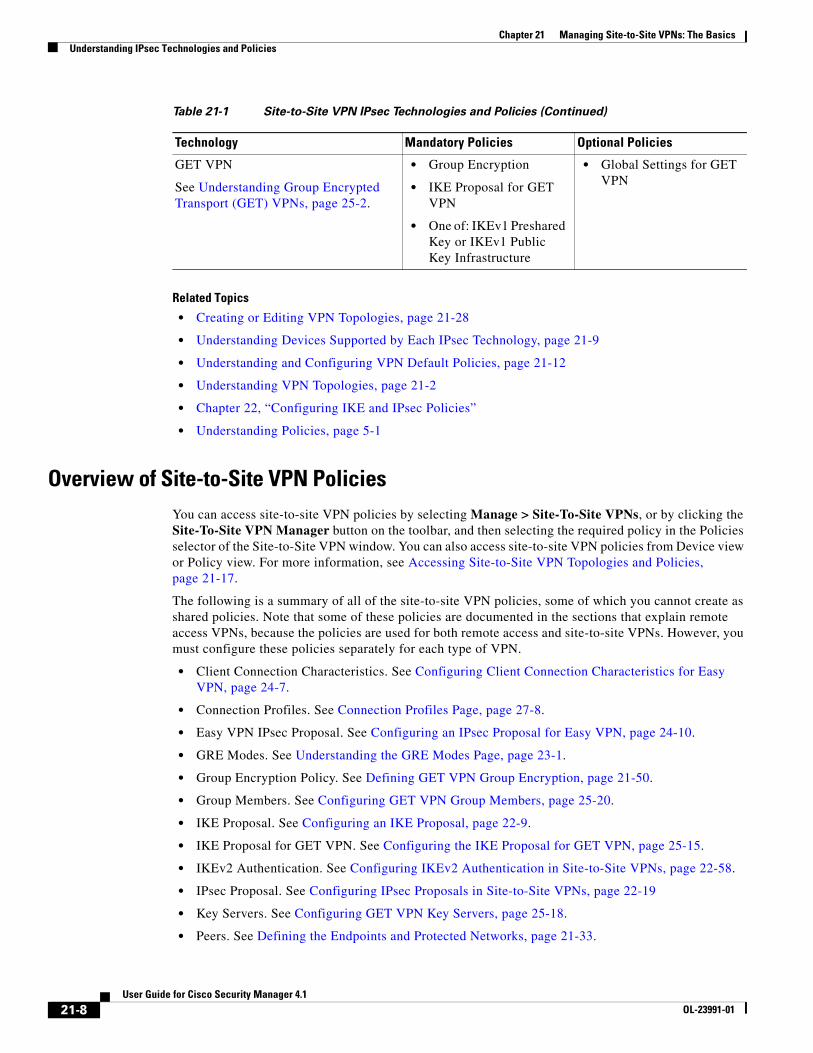
GET VPN
See Understanding Group Encrypted Transport (GET) VPNs, page 25-2.
• Group Encryption
• IKE Proposal for GET VPN
• One of: IKEv1 Preshared Key or IKEv1 Public Key Infrastructure
• Global Settings for GET VPN
Table 21-1 Site-to-Site VPN IPsec Technologies and Policies (Continued)
Technology Mandatory Policies Optional Policies
21-8User Guide for Cisco Security Manager 4.1
OL-23991-01
Chapter 21 Managing Site-to-Site VPNs: The BasicsUnderstanding IPsec Technologies and Policies
• IKEv1 Preshared Key. See Configuring IKEv1 Preshared Key Policies, page 22-40.
• IKEv1 Public Key Infrastructure. See Configuring IKEv1 Public Key Infrastructure Policies in Site-to-Site VPNs, page 22-46.
• Server Load Balance. See Configuring Server Load Balancing in Large Scale DMVPN, page 23-18.
• User Group Policy. See Configuring a User Group Policy for Easy VPN, page 24-14.
• VPN Global Settings. See Configuring VPN Global Settings, page 22-26.
• Global Settings for GET VPN. See Configuring Global Settings for GET VPN, page 25-16.
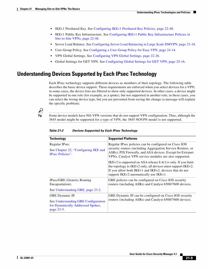
Understanding Devices Supported by Each IPsec TechnologyEach IPsec technology supports different devices as members of their topology. The following table describes the basic device support. These requirements are enforced when you select devices for a VPN; in some cases, the device lists are filtered to show only supported devices. In other cases, a device might be supported in one role (for example, as a spoke), but not supported in another role; in these cases, you can select the wrong device type, but you are prevented from saving the change (a message will explain the specific problem).
Tip Some device models have NO-VPN versions that do not support VPN configuration. Thus, although the 3845 model might be supported for a type of VPN, the 3845 NOVPN model is not supported.
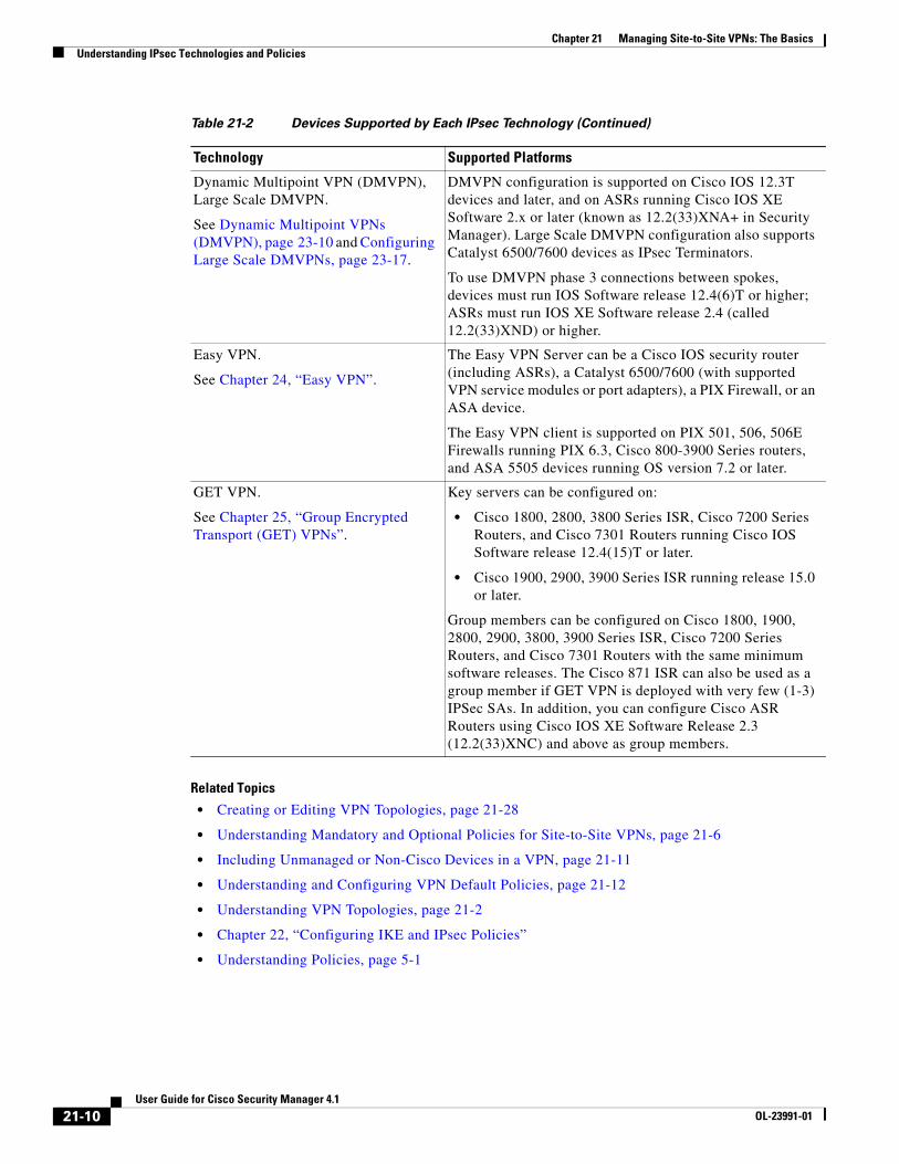
Table 21-2 Devices Supported by Each IPsec Technology
Technology Supported Platforms
Regular IPsec
See Chapter 22, “Configuring IKE and IPsec Policies”.
Regular IPsec policies can be configured on Cisco IOS security routers (including Aggregation Service Routers, or ASRs), PIX Firewalls, and ASA devices. Except for Extranet VPNs, Catalyst VPN service modules are also supported.
IKEv2 is supported on ASA release 8.4(1)+ only. If you limit the topology to IKEv2 only, all devices must support IKEv2. If you allow both IKEv1 and IKEv2, devices that do not support IKEv2 automatically use IKEv1.
IPsec/GRE (Generic Routing Encapsulation).
See Understanding GRE, page 23-2.
GRE policies can be configured on Cisco IOS security routers (including ASRs) and Catalyst 6500/7600 devices.
GRE Dynamic IP.
See Understanding GRE Configuration for Dynamically Addressed Spokes, page 23-5.
GRE Dynamic IP can be configured on Cisco IOS security routers (including ASRs) and Catalyst 6500/7600 devices.
21-9User Guide for Cisco Security Manager 4.1
OL-23991-01
Chapter 21 Managing Site-to-Site VPNs: The BasicsUnderstanding IPsec Technologies and Policies
Related Topics
• Creating or Editing VPN Topologies, page 21-28
• Understanding Mandatory and Optional Policies for Site-to-Site VPNs, page 21-6
• Including Unmanaged or Non-Cisco Devices in a VPN, page 21-11
• Understanding and Configuring VPN Default Policies, page 21-12
• Understanding VPN Topologies, page 21-2
• Chapter 22, “Configuring IKE and IPsec Policies”
• Understanding Policies, page 5-1
Dynamic Multipoint VPN (DMVPN), Large Scale DMVPN.
See Dynamic Multipoint VPNs (DMVPN), page 23-10 and Configuring Large Scale DMVPNs, page 23-17.
DMVPN configuration is supported on Cisco IOS 12.3T devices and later, and on ASRs running Cisco IOS XE Software 2.x or later (known as 12.2(33)XNA+ in Security Manager). Large Scale DMVPN configuration also supports Catalyst 6500/7600 devices as IPsec Terminators.
To use DMVPN phase 3 connections between spokes, devices must run IOS Software release 12.4(6)T or higher; ASRs must run IOS XE Software release 2.4 (called 12.2(33)XND) or higher.
Easy VPN.
See Chapter 24, “Easy VPN”.
The Easy VPN Server can be a Cisco IOS security router (including ASRs), a Catalyst 6500/7600 (with supported VPN service modules or port adapters), a PIX Firewall, or an ASA device.
The Easy VPN client is supported on PIX 501, 506, 506E Firewalls running PIX 6.3, Cisco 800-3900 Series routers, and ASA 5505 devices running OS version 7.2 or later.
GET VPN.
See Chapter 25, “Group Encrypted Transport (GET) VPNs”.
Key servers can be configured on:
• Cisco 1800, 2800, 3800 Series ISR, Cisco 7200 Series Routers, and Cisco 7301 Routers running Cisco IOS Software release 12.4(15)T or later.
• Cisco 1900, 2900, 3900 Series ISR running release 15.0 or later.
Group members can be configured on Cisco 1800, 1900, 2800, 2900, 3800, 3900 Series ISR, Cisco 7200 Series Routers, and Cisco 7301 Routers with the same minimum software releases. The Cisco 871 ISR can also be used as a group member if GET VPN is deployed with very few (1-3) IPSec SAs. In addition, you can configure Cisco ASR Routers using Cisco IOS XE Software Release 2.3 (12.2(33)XNC) and above as group members.
Table 21-2 Devices Supported by Each IPsec Technology (Continued)
Technology Supported Platforms
21-10User Guide for Cisco Security Manager 4.1
OL-23991-01

Chapter 21 Managing Site-to-Site VPNs: The BasicsUnderstanding IPsec Technologies and Policies
Including Unmanaged or Non-Cisco Devices in a VPNYour VPN might include devices that you cannot, or should not, manage in Security Manager. These include:
• Cisco devices that Security Manager supports, but for which your organization is not responsible. For example, you might have a VPN that includes spokes in networks managed by other organizations within your company, or a connection to a service provider or partner network.
• Non-Cisco devices. You cannot use Security Manager to create and deploy configurations to non-Cisco devices.
You have two options for handling these kinds of devices:
• If the connection is a regular IPsec point-to-point connection, you can configure the connection as an Extranet VPN as described in Creating or Editing Extranet VPNs, page 21-62.
• For other types of connections, you can include these devices in the Security Manager inventory as “unmanaged” devices. These devices can serve as endpoints in a VPN topology, but Security Manager does not discover any configurations from the device, nor does it deploy configurations to them.
When the Extranet VPN option will not work, you must do the following before you can add an unmanaged device to a VPN topology:
• Manually add the device as an unmanaged device to the device inventory using the procedure described in Adding Devices by Manual Definition, page 3-21. Ensure that you make the following selections:
– Select a Cisco device type that is comparable to the device you are adding in terms of VPN-supported technologies. The device type controls the types of VPN topologies to which you can add the device. For example, for GRE/DMVPN, you might select an integrated services router such as an 1800 or 2800 series, whereas in Easy VPN you could also select an ASA or PIX device if appropriate.
– Deselect the Manage in Cisco Security Manager option. This is very important, because the default is to make all new devices managed devices. If you forget to do this while adding the device, you can deselect the option later on the General tab in the device properties (right-click the device and select Device Properties).
• Using the interface policy for the device, define the external VPN interface to which managed devices will point. Because the device is unmanaged, your definitions in this policy are never configured on the device; the policy simply represents what you have configured on the device outside of Security Manager.
Related Topics
• Understanding Devices Supported by Each IPsec Technology, page 21-9
• Selecting Devices for Your VPN Topology, page 21-32
• Creating or Editing VPN Topologies, page 21-28
21-11User Guide for Cisco Security Manager 4.1
OL-23991-01
Chapter 21 Managing Site-to-Site VPNs: The BasicsUnderstanding IPsec Technologies and Policies
Understanding and Configuring VPN Default PoliciesFor most VPN policies that are mandatory, Security Manager includes “factory default” settings for the policies. These defaults are generic, and might not be appropriate for your network, but they do allow you to complete the creation of a VPN without having to stop and start over when you do not have the needed shared policy configured. Therefore, you can, and should, create your own default VPN policies for mandatory policies. You can also create defaults for certain optional policies.
Before configuring new defaults, consider the types of VPNs you are likely to configure, then review the types of policies for which you can create defaults. Select Tools > Security Manager Administration, then select VPN Policy Defaults from the table of contents. Select the tabs for the desired IPsec technologies to see which policies are available. If a policy is assigned Factory Default, or if this option is available from the drop-down list, the policy is mandatory; other policies are optional. You can also create default policies for remote access VPNs, and for site-to-site endpoint configurations. Click the View Content button next to a selected policy to see the policy definition.
The following procedure explains how to create and use VPN policy defaults.
Tips
• When you configure VPN default policies, you are selecting shared policies. Although you can configure only one default per policy per IPsec technology, users can select different shared policies when configuring VPNs. Thus, you might want to configure more than one shared policy that users can select, and configure the most commonly-used policy as the default policy. For more information about how users can select different policies when configuring a VPN, see Assigning Initial Policies (Defaults) to a New VPN Topology, page 21-57.
• Although the IKEv2 Authentication policy is a mandatory policy for topologies that allow IKEv2 negotiations, there are no IKEv2 Authentication factory default settings, and you cannot create IKEv2 Authentication shared policies. Therefore, whenever you allow IKEv2 in a topology, you must manually configure the IKEv2 Authentication policy before the topology is valid.
• The Public Key Infrastructure policy is required for IKEv1 if you configure the IKE Proposal policy to use certificate authentication. However, there are no factory default settings for this policy, so if you intend to use certificate authentication for IKEv1, consider creating default Public Key Infrastructure policies.
• Keep in mind that any change to a shared policy affects all VPNs that are using the policy. This can make it easy to implement across-the-board changes that are required for every VPN. However, after creating the VPN, the user can switch from a shared policy to a local policy, so that any changes to the configuration must be done specifically for the VPN topology. For more information about shared policies, see Managing Shared Policies in Policy View, page 5-47.
• These default policies do not apply when you create Extranet VPNs. With Extranet VPNs, you must always configure the settings for mandatory policies as part of the normal wizard flow.
Step 1 Create the default policies. All default policies are shared policies.
a. In Policy view (select View > Policy View), select the policy for which you want to configure defaults. The policies are in the Site-to-Site VPN or Remote Access VPN folders.
b. Click the Create a Policy (+) button at the bottom of the shared policy selector, enter a name for the policy, and click OK.
c. Configure the desired settings. Click the Help (?) button in the toolbar to get reference information about the settings available in the selected policy.
d. Repeat the process until you have created at least one shared policy for each policy for which you want to define a default policy.
21-12User Guide for Cisco Security Manager 4.1
OL-23991-01

Chapter 21 Managing Site-to-Site VPNs: The BasicsUnderstanding IPsec Technologies and Policies
Step 2 If desired, create defaults for the VPN endpoints. These defaults are interface role objects, which identify the interface names used for VPN connections (for example, GigabitEthernet0/1). Create separate roles for internal and external VPN interfaces.
a. Select Manage > Policy Objects to open the Policy Object Manager Window, page 6-3.
b. Select Interface Roles from the table of contents.
c. Click the New Object (+) button, enter the interface name patterns that identify the most commonly used interfaces for VPN internal or external interfaces in your network, and click OK.
For more information about interface roles and the wildcards you can use to configure them, see Understanding Interface Role Objects, page 6-56 and Creating Interface Role Objects, page 6-57.
Step 3 Submit the policies and policy objects to the database. You will have to resolve any validation errors.
• In non-Workflow mode, select File > Submit.
• In Workflow mode without an activity approver, select Activities > Approve Activity.
• In Workflow mode with an activity approver, select Activities > Submit Activity. You will have to wait for the activity to be approved before you can select the policies and objects as defaults.
Step 4 Select your newly-configured policies and policy objects as VPN policy defaults.
a. Select Tools > Security Manager Administration, and then select VPN Policy Defaults from the table of contents (see VPN Policy Defaults Page, page 11-40).
b. Select the desired tabs, then select the policies you configured from the drop-down lists for each of the mandatory or optional policies for which you configured defaults.
On the S2S Endpoints tab, select the appropriate interface role objects.
c. Click Save to save your defaults.
The next time a user runs the Create VPN wizard, the defaults you selected will be used as the wizard’s defaults. Users can select any other shared policy or interface role to override the default.
Using Device Overrides to Customize VPN Policies Many VPN policies use Security Manager policy objects in their configuration. Policy objects are containers that allow you to create reusable configurations.
Because a VPN policy applies to every device in a VPN topology, you might need to make modifications to a policy object used in a policy for certain devices within the VPN topology. There might even be situations where you need to make modifications for all devices within a topology. You accomplish these modifications with device-level overrides on the policy objects.
For example, when defining a PKI policy, you need to select a PKI enrollment object. If the hub of your VPN uses a different CA server than the spokes, you must use device-level overrides to specify the CA server used by the hub. Although the PKI policy references a single PKI enrollment object, the actual CA server represented by this object differs for the hub, based on the device-level override you define.
To enable a policy object to be overridden, you must select the Allow Override per Device option in the policy object definition. You can then create device-level overrides. For more information about overriding a VPN policy object at the device level, see the following topics:
• Understanding Policy Object Overrides for Individual Devices, page 6-13
• Allowing a Policy Object to Be Overridden, page 6-14
• Creating or Editing Object Overrides for a Single Device, page 6-14
21-13User Guide for Cisco Security Manager 4.1
OL-23991-01
Chapter 21 Managing Site-to-Site VPNs: The BasicsUnderstanding IPsec Technologies and Policies
• Creating or Editing Object Overrides for Multiple Devices At A Time, page 6-15
Understanding VRF-Aware IPsecOne obstacle to successfully deploying peer-to-peer VPNs is the separation of routing tables, and the use of overlapping addresses, which usually results from using private IP addresses in customer networks. The VRF-Aware IPsec feature, which introduces IPsec tunnel mapping to Multiprotocol Label Switching (MPLS) VPNs, solves this problem.
The VRF-Aware IPsec feature enables you to map IPsec tunnels to Virtual Routing Forwarding (VRF) instances, using a single public-facing address. A VRF instance defines the VPN membership of a customer site attached to the Provider Edge (PE) router. A VRF comprises an IP routing table, a derived Cisco Express Forwarding (CEF) table, a set of interfaces that use the forwarding table, and a set of rules and routing protocol parameters that control the information that is included in the routing table. A set of routing and CEF tables is maintained for each VPN customer across the MPLS/VPN network.
Since each VPN has its own routing and forwarding table in the router, any customer or site that belongs to a VPN is provided access only to the set of routes contained within that table. Any PE router maintains a number of routing tables and a global routing table per VPN, which can be used to reach other routers in the provider network. Effectively, a number of virtual routers are created in a single physical router. Across the MPLS core to the other PE routers, this routing separation is maintained by adding unique VPN identifiers, such as the route distinguisher (RD).
Note VRF-Aware IPsec can also be configured on devices in a remote access VPN. For more information, see Configuring Dynamic VTI/VRF Aware IPsec in Remote Access VPNs (IOS Devices), page 29-7.
In Security Manager, you can configure VRF-Aware IPsec in your hub-and spoke VPN topology, with either a single device providing all functionality (“one-box” solution) or with multiple devices, each providing a part of the functionality (“two-box” solution). The solution of one device providing all the functionality can affect performance by overloading the system, whereas separating the functionality in a two-box solution provides better scaling for each function.
The following topics describe:
• VRF-Aware IPsec One-Box Solution, page 21-14
• VRF-Aware IPsec Two-Box Solution, page 21-15
• Enabling and Disabling VRF on Catalyst Switches and 7600 Devices, page 21-17
For information on configuring VRF-aware IPsec, see Configuring VRF Aware IPsec Settings, page 21-45.
VRF-Aware IPsec One-Box Solution
In the one-box solution, IPsec tunnels terminate on a Cisco IOS router, which serves as the Provider Edge (PE) device. The PE device maps these tunnels to the appropriate MPLS/VPN network and serves as the IPsec Aggregator, by performing IPsec encryption and decryption from the Customer Edge (CE) devices.
Note The configuration of routing between the PE device and the MPLS cloud is done by Cisco IP Solution Center. See the Cisco IP Solution Center MPLS VPN User Guide.
21-14User Guide for Cisco Security Manager 4.1
OL-23991-01

Chapter 21 Managing Site-to-Site VPNs: The BasicsUnderstanding IPsec Technologies and Policies
The following illustration shows the topology of a one-box solution.
Figure 21-4 VRF-Aware IPsec One-Box Solution
Related Topics
• Understanding VRF-Aware IPsec, page 21-14
• Configuring VRF Aware IPsec Settings, page 21-45
• Defining the Endpoints and Protected Networks, page 21-33
VRF-Aware IPsec Two-Box Solution
In the two-box solution, the PE device does just the MPLS mapping, while a separate IPsec Aggregator device does the IPsec encryption and decryption from the CEs.
Note Security Manager fully manages the IPsec Aggregator, including routing to the PE device. The PE device is fully managed by Cisco IP Solution Center. This includes routing between the PE device and the MPLS cloud, and routing from the PE to the IPsec Aggregator. For more information, see the Cisco IP Solution Center MPLS VPN User Guide.
The following illustration shows the topology of a two-box solution.
21-15User Guide for Cisco Security Manager 4.1
OL-23991-01
Chapter 21 Managing Site-to-Site VPNs: The BasicsUnderstanding IPsec Technologies and Policies
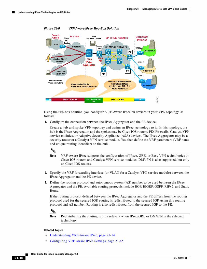
Figure 21-5 VRF-Aware IPsec Two-Box Solution
Using the two-box solution, you configure VRF-Aware IPsec on devices in your VPN topology, as follows:
1. Configure the connection between the IPsec Aggregator and the PE device.
Create a hub-and-spoke VPN topology and assign an IPsec technology to it. In this topology, the hub is the IPsec Aggregator, and the spokes may be Cisco IOS routers, PIX Firewalls, Catalyst VPN service modules, or Adaptive Security Appliance (ASA) devices. The IPsec Aggregator may be a security router or a Catalyst VPN service module. You then define the VRF parameters (VRF name and unique routing identifier) on the hub.
Note VRF-Aware IPsec supports the configuration of IPsec, GRE, or Easy VPN technologies on Cisco IOS routers and Catalyst VPN service modules. DMVPN is also supported, but only on Cisco IOS routers.
2. Specify the VRF forwarding interface (or VLAN for a Catalyst VPN service module) between the IPsec Aggregator and the PE device.
3. Define the routing protocol and autonomous system (AS) number to be used between the IPsec Aggregator and the PE. Available routing protocols include BGP, EIGRP, OSPF, RIPv2, and Static Route.
If the routing protocol defined between the IPsec Aggregator and the PE differs from the routing protocol used for the secured IGP, routing is redistributed to the secured IGP, using this routing protocol and AS number. Routing is also redistributed from the secured IGP to the PE.
Note Redistributing the routing is only relevant when IPsec/GRE or DMVPN is the selected technology.
Related Topics
• Understanding VRF-Aware IPsec, page 21-14
• Configuring VRF Aware IPsec Settings, page 21-45
21-16User Guide for Cisco Security Manager 4.1
OL-23991-01
Chapter 21 Managing Site-to-Site VPNs: The BasicsAccessing Site-to-Site VPN Topologies and Policies
• Defining the Endpoints and Protected Networks, page 21-33
Enabling and Disabling VRF on Catalyst Switches and 7600 Devices
Deployment fails when you change the virtual routing and forwarding (VRF) mode on the Catalyst switches and 7600 hub of an existing site-to-site VPN. For example, if you initially configured VRF in the Create VPN wizard and deployed, but later return to the Peers policy and deselect the Enable VRF Settings check box, deployment fails. (This setting is found in the VRF Aware IPSec tab of the Edit Endpoints dialog box; see Configuring VRF Aware IPsec Settings, page 21-45.) Deployment likewise fails if you try to enable VRF on a VPN that was not initially configured with it.
You cannot change the VRF mode on a Catalyst 6500/7600 during VPN operation. This restriction applies only to Catalyst 6500/7600 hubs, not to any other device type.
This restriction does not apply to changes made to the VRF settings themselves. For example, if VRF is configured on the VPN topology, you can return to the Peers policy and change the VRF name or route distinguisher.
If you need to change the VRF mode of a VPN, and you are using Catalyst 6500/7600 devices as hubs, use the following procedure.
Related topics
• Understanding VRF-Aware IPsec, page 21-14
• VRF-Aware IPsec One-Box Solution, page 21-14
• VRF-Aware IPsec Two-Box Solution, page 21-15
Step 1 Delete the VPN topology from Security Manager.
Step 2 Deploy your changes.
Step 3 Reload (restart) the Catalyst 6500/7600 device.
Step 4 Right-click the device in Security Manager and select Discover Policies on Device. Perform a complete policy rediscovery.
Step 5 Open the Create VPN wizard and redefine the VPN topology. At this point, you can select a different VRF mode. See Configuring VRF Aware IPsec Settings, page 21-45 and Creating or Editing VPN Topologies, page 21-28.
Accessing Site-to-Site VPN Topologies and PoliciesYou can use the following methods to access and configure site-to-site VPN topologies and policies:
• Site-to-Site VPN Manager—This is the main tool for configuring VPN topologies. You can view a list of all site-to-site VPNs configured in Security Manager and edit their configurations and policies, including device membership. For information on using this tool, see Site-to-Site VPN Manager Window, page 21-18.
• Site-to-Site VPN policy in Device view—When you select a device in device view, you can select the Site-to-Site VPN policy in the Policies selector to see a list of all site-to-site VPNs in which the device participates and edit those topologies. You can also create new VPNs, or select a VPN and open the Site-to-Site VPN Manager to edit the policies for the selected VPN. This device view policy is essentially a short-cut into the Site-to-Site VPN Manager. For more information about
21-17User Guide for Cisco Security Manager 4.1
OL-23991-01
Chapter 21 Managing Site-to-Site VPNs: The BasicsAccessing Site-to-Site VPN Topologies and Policies
using this policy, see Configuring VPN Topologies in Device View, page 21-19.
• Site-to-Site VPN folder in Policy view—Policy view is used to create shared policies. Many of the site-to-site VPN policies are shareable. Thus, you can configure shared policies that you can assign to more than one VPN topology while configuring the topology in the Site-to-Site VPN Manager. You can configure shared policies as defaults for the Create VPN wizard, as described in Understanding and Configuring VPN Default Policies, page 21-12.
You can also create shared policies from the Site-to-Site VPN Manager window in much the same way you can create them from local policies in Device view, although all sharing commands in the Site-to-Site VPN Manager window are available only on the right-click context menu (when right-clicking a shareable policy).
For more information on creating shared policies in Policy view, see Managing Shared Policies in Policy View, page 5-47.
Site-to-Site VPN Manager WindowThe Site-to-Site VPN Manager lists all site-to-site VPNs configured in Security Manager. The VPNs selector, in the upper left pane of the window, lists all existing VPN topologies (see Understanding VPN Topologies, page 21-2). An icon indicates the type of VPN (hub and spoke, point to point, or full mesh).To view or edit a topology, select it, and its policies are loaded into the policy selector in the lower left pane. Select a policy to see its definition in the right pane.
To open the Site-to-Site VPN Manager, click the Site-To-Site VPN Manager button on the toolbar or select Manage > Site-To-Site VPNs.
Use the Site-to-Site VPN Manager window to:
• Create, edit, and delete VPN topologies.
– To create a VPN topology, click the Create VPN Topology (+) button above the VPN selector and select the type of topology you want to create from the options that are displayed. This action opens the Create VPN Wizard or the Create Extranet VPN wizard. For more information, see Creating or Editing VPN Topologies, page 21-28 or Creating or Editing Extranet VPNs, page 21-62.
– To edit a VPN topology, select it and click the Edit VPN Topology (pencil) button, or right-click it and select Edit. This opens the Edit VPN or Edit Extranet VPN dialog box, which contains the most of the same pages as the Create VPN wizard in a tabbed layout.
– To delete a VPN topology, select it and click the Delete VPN Topology (trash can) icon, or right-click it and select Delete. You are asked to confirm the deletion. See Deleting a VPN Topology, page 21-66.
• View detailed information about each VPN topology; select the topology, then select the VPN Summary policy. See Viewing a Summary of a VPN Topology’s Configuration, page 21-58.
• View and configure the endpoints defined for a VPN topology. You can see endpoints on the Endpoints tab or when editing a VPN topology, or by selecting the Peers policy. For GET VPN topologies, there is no Peers policy; instead, use the Key Servers and Group Members policies to view and configure endpoints. For Extranet VPNs, the endpoints are on the Device Selection tab when editing the VPN, or also in the Peers policy.
• View and edit the policies assigned to a VPN topology, assign shared policies, or create shared policies from existing policies. For information on individual policies, see Overview of Site-to-Site VPN Policies, page 21-8.
21-18User Guide for Cisco Security Manager 4.1
OL-23991-01
Chapter 21 Managing Site-to-Site VPNs: The BasicsSite-To-Site VPN Discovery
The options and methods for configuring shared policies from the Site-to-Site VPN Manager are the same as those from Device view, as explained in the sections under Working with Shared Policies in Device View or the Site-to-Site VPN Manager, page 5-34 and Using the Policy Banner, page 5-35. You can share, assign, unassign, edit assignments, and rename policies, but no VPN policies allow inheritance. To perform these tasks, select the VPN topology, then right-click the desired policy and select the desired command.
You can also use Policy view to configure shared VPN policies.
Configuring VPN Topologies in Device ViewUse the Site-to-Site VPN Device view policy to view and edit the site-to-site VPN topologies to which a device belongs, if any. You can edit the VPN policies and change whether the device participates in the topology. You can also create new VPN topologies.
This policy is essentially an access point for the Site-to-Site VPN Manager (see Site-to-Site VPN Manager Window, page 21-18).
To open this policy, in Device view, select the desired device and then select Site-to-Site VPN from the Policy selector.
The VPN topologies table lists all of the site-to-site VPNs to which this device belongs. Information includes the type of VPN, its name, IPSec technology, and description.
• To add a VPN, click the Create VPN Topology button, or right-click in the table and select Create VPN Topology and select the type of topology you want to create from the options that are displayed. This action opens the Create VPN Wizard or the Create Extranet VPN wizard. For more information, see Creating or Editing VPN Topologies, page 21-28 or Creating or Editing Extranet VPNs, page 21-62.
• To edit a VPN, select it and click the Edit VPN Topology button, right-click the VPN and select Edit VPN Topology, or simply double-click the entry. This opens the Edit VPN or Edit Extranet VPN dialog box, which is a tabbed version of the Create VPN wizard (see Creating or Editing VPN Topologies, page 21-28 or Creating or Editing Extranet VPNs, page 21-62).
• To edit the policies for a VPN, select it and click the Edit VPN Policies button. The Site-to-Site VPN Window opens displaying information about the VPN topology; select the desired policy from the Policies selector to edit it.
• To delete a VPN, select it and click the Delete VPN Topology button, or right-click the VPN and select Delete VPN Topology. You are asked to confirm the deletion. For more information, see Deleting a VPN Topology, page 21-66.
Site-To-Site VPN DiscoveryYou can discover the VPN topologies that are already deployed in your network so that you can use Security Manager to manage them. Your VPN configurations are brought into Security Manager and displayed as site-to-site VPN policies.
Except for Extranet VPNs, you can also rediscover the configurations of existing VPN topologies that are already managed with Security Manager. For information about Site-to-Site VPN rediscovery, see Rediscovering Site-to-Site VPNs, page 21-26.
21-19User Guide for Cisco Security Manager 4.1
OL-23991-01
Chapter 21 Managing Site-to-Site VPNs: The BasicsSite-To-Site VPN Discovery
Note You can also discover configurations on devices in remote access VPNs that are already deployed in your network. See Discovering Remote Access VPN Policies, page 26-11.
These topics provide information about Site-to-Site VPN discovery:
• Supported and Unsupported Technologies and Topologies for VPN Discovery, page 21-20
• Prerequisites for VPN Discovery, page 21-21
• VPN Discovery Rules, page 21-21
• Discovering Site-to-Site VPNs, page 21-24
• Defining or Repairing Discovered VPNs with Multiple Spoke Definitions, page 21-25
• Rediscovering Site-to-Site VPNs, page 21-26
Supported and Unsupported Technologies and Topologies for VPN DiscoveryThis topic lists the technologies and topologies that Security Manager can discover, as well as the VPN features that are provisioned by Security Manager but cannot be discovered.
Supported Technologies for VPN Discovery
• IPsec, including LAN-to-LAN configurations on ASA devices.
• IPsec + GRE
• IPsec + GRE dynamic IP
• DMVPN
• Easy VPN
• GET VPN
Supported Topologies for VPN Discovery
• Point to point
• Hub and spoke
• Full mesh
• Extranet VPN (point-to-point to an unmanaged device)
VPN Features Provisioned by Security Manager but Unsupported for VPN Discovery
• Large Scale DMVPN with IPsec Terminator (high-concentration hub)
• VRF-Aware IPsec
• Dial backup
• IPsec and ISAKMP profiles for Easy VPN
• Easy VPN with High Availability
If you define and deploy policies of these types using Security Manager, your policies overwrite the device configurations that were not discovered. Therefore, if you want Security Manager to manage existing configurations, you should define policies that match the existing configurations as closely as possible. (Use Tools > Preview Configuration to examine the results before deploying.) The VPN
21-20User Guide for Cisco Security Manager 4.1
OL-23991-01

Chapter 21 Managing Site-to-Site VPNs: The BasicsSite-To-Site VPN Discovery
provisioning mechanism leverages the content of the existing configuration as much as possible (assuming the content matches the policies configured in Security Manager), but does not retain the naming conventions used in the CLI commands.
Related Topics
• Prerequisites for VPN Discovery, page 21-21
• VPN Discovery Rules, page 21-21
• Discovering Site-to-Site VPNs, page 21-24
Prerequisites for VPN DiscoveryFor successful VPN discovery, the following prerequisites must be met:
• Except for Extranet VPNs, all devices participating in the VPN must be added to the Security Manager inventory.
• You must provide Security Manager with some basic information about the VPN. The VPN discovery wizard prompts you for the following information:
– VPN topology (hub and spoke, point to point, full mesh, Extranet).
– VPN technology (Regular IPsec, IPsec/GRE, GRE dynamic IP, DMVPN, Easy VPN, GET VPN).
– Devices in the VPN and their roles (hub/spoke). For Extranet VPNs, you specify the managed device only.
– Source of the VPN configuration. The VPN can be discovered directly from the live network or from Security Manager’s Configuration Archive.
• Each device in the VPN must have a crypto map associated with a physical interface. This rule does not apply to the remote (unmanaged) devices in an Extranet VPN.
• If you use OSPF as your routing protocol in a VPN topology, all devices in the VPN must use the same OSPF process number.
• Each PIX 6.3 or ASA 5505 client device in an Easy VPN topology must have a vpnclient configuration.
Related Topics
• Supported and Unsupported Technologies and Topologies for VPN Discovery, page 21-20
• VPN Discovery Rules, page 21-21
• Discovering Site-to-Site VPNs, page 21-24
VPN Discovery RulesThe following table describes the rules by which Security Manager translates and discovers your VPN configurations, and how it handles instances where your configuration on the device does not match what is supported by Security Manager.
21-21User Guide for Cisco Security Manager 4.1
OL-23991-01
Chapter 21 Managing Site-to-Site VPNs: The BasicsSite-To-Site VPN Discovery
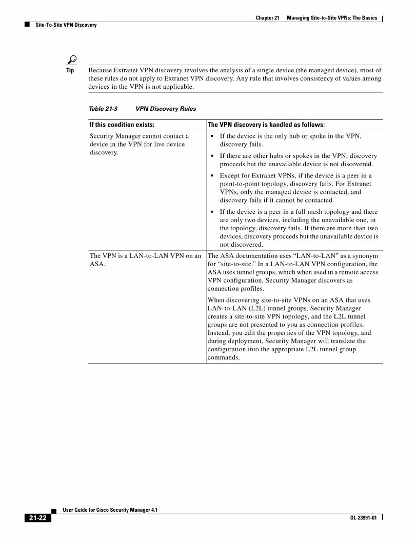
Tip Because Extranet VPN discovery involves the analysis of a single device (the managed device), most of these rules do not apply to Extranet VPN discovery. Any rule that involves consistency of values among devices in the VPN is not applicable.
Table 21-3 VPN Discovery Rules
If this condition exists: The VPN discovery is handled as follows:
Security Manager cannot contact a device in the VPN for live device discovery.
• If the device is the only hub or spoke in the VPN, discovery fails.
• If there are other hubs or spokes in the VPN, discovery proceeds but the unavailable device is not discovered.
• Except for Extranet VPNs, if the device is a peer in a point-to-point topology, discovery fails. For Extranet VPNs, only the managed device is contacted, and discovery fails if it cannot be contacted.
• If the device is a peer in a full mesh topology and there are only two devices, including the unavailable one, in the topology, discovery fails. If there are more than two devices, discovery proceeds but the unavailable device is not discovered.
The VPN is a LAN-to-LAN VPN on an ASA.
The ASA documentation uses “LAN-to-LAN” as a synonym for “site-to-site.” In a LAN-to-LAN VPN configuration, the ASA uses tunnel groups, which when used in a remote access VPN configuration, Security Manager discovers as connection profiles.
When discovering site-to-site VPNs on an ASA that uses LAN-to-LAN (L2L) tunnel groups, Security Manager creates a site-to-site VPN topology, and the L2L tunnel groups are not presented to you as connection profiles. Instead, you edit the properties of the VPN topology, and during deployment, Security Manager will translate the configuration into the appropriate L2L tunnel group commands.
21-22User Guide for Cisco Security Manager 4.1
OL-23991-01
Chapter 21 Managing Site-to-Site VPNs: The BasicsSite-To-Site VPN Discovery
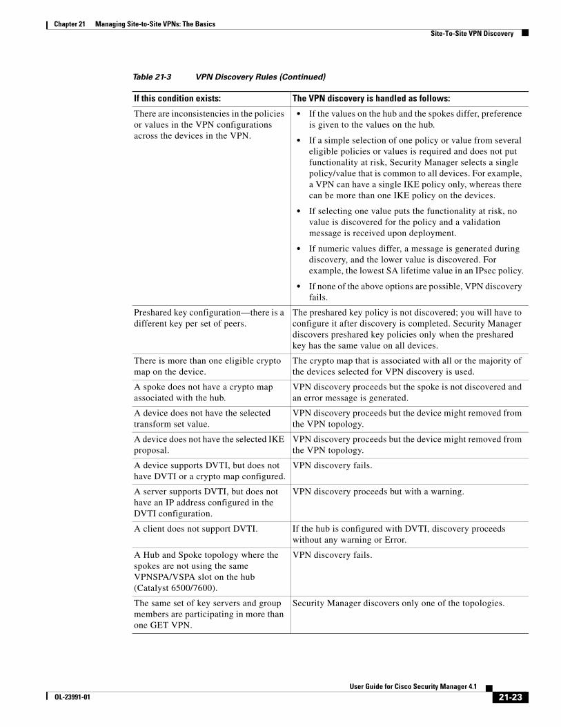
There are inconsistencies in the policies or values in the VPN configurations across the devices in the VPN.
• If the values on the hub and the spokes differ, preference is given to the values on the hub.
• If a simple selection of one policy or value from several eligible policies or values is required and does not put functionality at risk, Security Manager selects a single policy/value that is common to all devices. For example, a VPN can have a single IKE policy only, whereas there can be more than one IKE policy on the devices.
• If selecting one value puts the functionality at risk, no value is discovered for the policy and a validation message is received upon deployment.
• If numeric values differ, a message is generated during discovery, and the lower value is discovered. For example, the lowest SA lifetime value in an IPsec policy.
• If none of the above options are possible, VPN discovery fails.
Preshared key configuration—there is a different key per set of peers.
The preshared key policy is not discovered; you will have to configure it after discovery is completed. Security Manager discovers preshared key policies only when the preshared key has the same value on all devices.
There is more than one eligible crypto map on the device.
The crypto map that is associated with all or the majority of the devices selected for VPN discovery is used.
A spoke does not have a crypto map associated with the hub.
VPN discovery proceeds but the spoke is not discovered and an error message is generated.
A device does not have the selected transform set value.
VPN discovery proceeds but the device might removed from the VPN topology.
A device does not have the selected IKE proposal.
VPN discovery proceeds but the device might removed from the VPN topology.
A device supports DVTI, but does not have DVTI or a crypto map configured.
VPN discovery fails.
A server supports DVTI, but does not have an IP address configured in the DVTI configuration.
VPN discovery proceeds but with a warning.
A client does not support DVTI. If the hub is configured with DVTI, discovery proceeds without any warning or Error.
A Hub and Spoke topology where the spokes are not using the same VPNSPA/VSPA slot on the hub (Catalyst 6500/7600).
VPN discovery fails.
The same set of key servers and group members are participating in more than one GET VPN.
Security Manager discovers only one of the topologies.
Table 21-3 VPN Discovery Rules (Continued)
If this condition exists: The VPN discovery is handled as follows:
21-23User Guide for Cisco Security Manager 4.1
OL-23991-01
Chapter 21 Managing Site-to-Site VPNs: The BasicsSite-To-Site VPN Discovery
Related Topics
• Supported and Unsupported Technologies and Topologies for VPN Discovery, page 21-20
• Prerequisites for VPN Discovery, page 21-21
• Discovering Site-to-Site VPNs, page 21-24
• Rediscovering Site-to-Site VPNs, page 21-26
Discovering Site-to-Site VPNsThis procedure describes how to discover a Site-to-Site VPN that is already working in your network but that has not yet been defined in Security Manager.
Related Topics
• Discovering Site-to-Site VPNs, page 21-24
• Discovering Policies, page 5-12
• Supported and Unsupported Technologies and Topologies for VPN Discovery, page 21-20
• Prerequisites for VPN Discovery, page 21-21
• VPN Discovery Rules, page 21-21
• Understanding Devices Supported by Each IPsec Technology, page 21-9
• Including Unmanaged or Non-Cisco Devices in a VPN, page 21-11
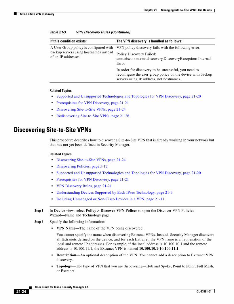
Step 1 In Device view, select Policy > Discover VPN Polices to open the Discover VPN Policies Wizard—Name and Technology page.
Step 2 Specify the following information:
• VPN Name—The name of the VPN being discovered.
You cannot specify the name when discovering Extranet VPNs. Instead, Security Manager discovers all Extranets defined on the device, and for each Extranet, the VPN name is a hyphenation of the local and remote IP addresses. For example, if the local address is 10.100.10.1 and the remote address is 10.100.11.1, the Extranet VPN is named 10.100.10.1-10.100.11.1.
• Description—An optional description of the VPN. You cannot add a description to Extranet VPN discovery.
• Topology—The type of VPN that you are discovering—Hub and Spoke, Point to Point, Full Mesh, or Extranet.
A User Group policy is configured with backup servers using hostnames instead of an IP addresses.
VPN policy discovery fails with the following error:
Policy Discovery Failed: com.cisco.nm.vms.discovery.DiscoveryException: Internal Error
In order for discovery to be successful, you need to reconfigure the user group policy on the device with backup servers using IP address, not hostnames.
Table 21-3 VPN Discovery Rules (Continued)
If this condition exists: The VPN discovery is handled as follows:
21-24User Guide for Cisco Security Manager 4.1
OL-23991-01
Chapter 21 Managing Site-to-Site VPNs: The BasicsSite-To-Site VPN Discovery
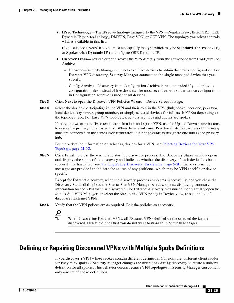
• IPsec Technology—The IPsec technology assigned to the VPN—Regular IPsec, IPsec/GRE, GRE Dynamic IP (sub-technology), DMVPN, Easy VPN, or GET VPN. The topology you select controls what is available in this list.
If you selected IPsec/GRE, you must also specify the type which may be Standard (for IPsec/GRE) or Spokes with Dynamic IP (to configure GRE Dynamic IP).
• Discover From—You can either discover the VPN directly from the network or from Configuration Archive.
– Network—Security Manager connects to all live devices to obtain the device configuration. For Extranet VPN discovery, Security Manager connects to the single managed device that you specify.
– Config Archive—Discovery from Configuration Archive is recommended if you deploy to configuration files instead of live devices. The most recent version of the device configuration in Configuration Archive is used for all devices.
Step 3 Click Next to open the Discover VPN Policies Wizard—Device Selection Page.
Step 4 Select the devices participating in the VPN and their role in the VPN (hub, spoke, peer one, peer two, local device, key server, group member, or simply selected devices for full-mesh VPNs) depending on the topology type. For Easy VPN topologies, servers are hubs and clients are spokes.
If there are two or more IPsec terminators in a hub-and-spoke VPN, use the Up and Down arrow buttons to ensure the primary hub is listed first. When there is only one IPsec terminator, regardless of how many hubs are connected to the same IPsec terminator, it is not possible to designate one hub as the primary hub.
For more detailed information on selecting devices for a VPN, see Selecting Devices for Your VPN Topology, page 21-32.
Step 5 Click Finish to close the wizard and start the discovery process. The Discovery Status window opens and displays the status of the discovery and indicates whether the discovery of each device has been successful or has failed (see Viewing Policy Discovery Task Status, page 5-20). Error or warning messages are provided to indicate the source of any problems, which may be VPN specific or device specific.
Except for Extranet discovery, when the discovery process completes successfully, and you close the Discovery Status dialog box, the Site-to-Site VPN Manager window opens, displaying summary information for the VPN that was discovered. For Extranet discovery, you must either manually open the Site-to-Site VPN Manager, or select the Site-to-Site VPN policy in Device view, to see the list of discovered Extranet VPNs.
Step 6 Verify that the VPN polices are as required. Edit the policies as necessary.
Tip When discovering Extranet VPNs, all Extranet VPNs defined on the selected device are discovered. Delete the ones that you do not want to manage in Security Manager.
Defining or Repairing Discovered VPNs with Multiple Spoke Definitions If you discover a VPN whose spokes contain different definitions (for example, different client modes for Easy VPN spokes), Security Manager changes the definitions during discovery to create a uniform definition for all spokes. This behavior occurs because VPN topologies in Security Manager can contain only one set of spoke definitions.
21-25User Guide for Cisco Security Manager 4.1
OL-23991-01
Chapter 21 Managing Site-to-Site VPNs: The BasicsSite-To-Site VPN Discovery
If you want to maintain your original definitions, or create a new VPN that has spokes with different definitions, you can choose one of two approaches:
• Define multiple VPN topologies in Security Manager, where each topology includes spokes containing matching spoke definitions.
• Define a FlexConfig policy that contains the specialized definition, then assign the policy to the spokes that require this definition, as described in the following procedure.
Related Topics
• Creating a New Shared Policy, page 5-50
• Creating FlexConfig Policy Objects, page 7-28
• Modifying Policy Assignments in Policy View, page 5-51
• Site-To-Site VPN Discovery, page 21-19
• Discovering Site-to-Site VPNs, page 21-24
• VPN Discovery Rules, page 21-21
Step 1 Create a shared FlexConfig policy in Policy view:
a. Select View > Policy View.
b. Right-click FlexConfigs in the Policy Type selector, then select New FlexConfigs Policy.
c. Enter a name for the policy and click OK.
Step 2 Define the FlexConfig policy by creating and selecting a FlexConfig object:
a. In the work area of Policy view, click the Add button on the Details tab.
b. In the FlexConfigs Selector, click the Create button in the lower-left corner of the window to open Add or Edit FlexConfig Dialog Box, page 7-30.
c. Define an appended FlexConfig object that contains the required client definition. For example, to define the client mode on an Easy VPN spoke, enter the following commands:
crypto ipsec client ezvpn CSM_EASY_VPN_CLIENT_1
mode client
exit
d. After you create the FlexConfig object, add it to the FlexConfig policy using the selector.
Step 3 In the work area of Policy view, use the Assignments tab to select the spokes to which this policy should be assigned, then click Save.
Step 4 Deploy the policy.
Rediscovering Site-to-Site VPNsYou can rediscover the configurations of existing VPN topologies that are already managed with Security Manager so that you do not have to recreate policies changes in the application.
The same rules by which Security Manager translates and discovers VPN configurations apply also to rediscovery. However, you can perform rediscovery only on devices that participate in a VPN topology, and you cannot make any changes to the IPsec technology or topology type. Only the configurations of
21-26User Guide for Cisco Security Manager 4.1
OL-23991-01

Chapter 21 Managing Site-to-Site VPNs: The BasicsSite-To-Site VPN Discovery
device specific policies, such as VPN interfaces and protected networks, and any High Availability (HA) policies that are configured on hubs, can be rediscovered. VPN global policies, such as IKE proposals or PKI enrollments, cannot be rediscovered. In addition, you cannot rediscover the following topologies:
• Easy VPN topologies with Dynamic VTI
• Extranet VPNs
This procedure describes how to rediscover the configurations of a Site-to-Site VPN topology that already exists in Security Manager.
Related Topics
• Discovering Site-to-Site VPNs, page 21-24
• Discovering Policies, page 5-12
• Prerequisites for VPN Discovery, page 21-21
• VPN Discovery Rules, page 21-21
• Understanding Devices Supported by Each IPsec Technology, page 21-9
• Including Unmanaged or Non-Cisco Devices in a VPN, page 21-11
Step 1 In the Site-to-Site VPN Manager window, right-click the VPN topology whose configurations you want to rediscover and select Rediscover Peers. This opens the Rediscover VPN Policies Wizard—Name and Technology page.
This page displays the type of topology and IPsec technology used in the VPN, which you cannot change.
Step 2 Specify the following information:
• VPN Discovery Name—The name of the rediscover VPN job.
• Description—An optional description of the VPN.
• Discover From—You can either rediscover the VPN directly from the network or from Configuration Archive.
– Network—Security Manager connects to all live devices to obtain the device configuration.
– Config Archive—Rediscovery from Configuration Archive is recommended if you deploy to configuration files instead of live devices. The most recent version of the device configuration in Configuration Archive is used for all devices.
Step 3 Click Next to open the Rediscover VPN Policies Wizard—Device Selection page.
Step 4 Select the devices whose peer level policies need to be rediscovered and their role in the VPN (hub, spoke, peer one, peer two, key server, group member, or simply selected devices for full-mesh VPNs) depending on the topology type. For Easy VPN topologies, servers are hubs and clients are spokes.
If there are two or more IPsec terminators in a hub-and-spoke VPN, use the Up and Down arrow buttons to ensure the primary hub is listed first. When there is only one IPsec terminator, regardless of how many hubs are connected to the same IPsec terminator, it is not possible to designate one hub as the primary hub.
For more detailed information on selecting devices for a VPN, see Selecting Devices for Your VPN Topology, page 21-32.
21-27User Guide for Cisco Security Manager 4.1
OL-23991-01

Chapter 21 Managing Site-to-Site VPNs: The BasicsCreating or Editing VPN Topologies
Step 5 Click Finish to close the wizard and start the rediscovery process. The Discovery Status window opens and displays the status of the rediscovery and indicates whether the rediscovery of each device has been successful or has failed (see Viewing Policy Discovery Task Status, page 5-20). Error or warning messages are provided to indicate the source of any problems, which may be VPN specific or device specific.
When the rediscovery process completes successfully, and you close the Discovery Status dialog box, the Site-to-Site VPN Manager window opens, displaying summary information for the VPN that was rediscovered.
Creating or Editing VPN TopologiesSecurity Manager supports three basic types of topologies with which you can create a site-to-site VPN. Use the Create VPN wizard to create a hub-and-spoke, point-to-point, or full mesh VPN topology across multiple device types. For more information about these topologies, see Understanding VPN Topologies, page 21-2.
Tip If you want to create an Extranet point-to-point VPN, read Creating or Editing Extranet VPNs, page 21-62 instead of this topic.
Creating a VPN topology involves specifying the devices and the networks that make up the site-to-site VPN. You define the devices and their roles (such as hub, spoke, peer, key server, group member), the VPN interfaces that are the source and destination endpoints of the VPN tunnel, and the protected networks that will be secured by the tunnel. When you create a VPN topology, you assign to it the IPsec technology (such as Regular IPSec, IPSec/GRE, GRE Dynamic IP, DMVPN, Large Scale DMVPN, Easy VPN, GET VPN) with which a predefined set of policies is associated. See Understanding Mandatory and Optional Policies for Site-to-Site VPNs, page 21-6.
Note When you complete the Create VPN wizard, your topology might be immediately deployable, because Security Manager provides defaults for mandatory policies. However, if you use Security Manager defaults, be sure to verify that the settings will work properly in your network. For more information, see Understanding and Configuring VPN Default Policies, page 21-12.
When you edit a VPN topology, the Edit VPN dialog box contains the same pages as the Create VPN wizard (except for the VPN defaults page), but the pages are laid out in a tabbed format rather than being presented as a wizard. The only exception is for GET VPN topologies, where you can edit only the name and description of the topology (you must edit GET VPN policies to change topology attributes, see Configuring GET VPN, page 25-12). Clicking OK on any tab in the dialog box saves your definitions on all the tabs. For all topologies, you must edit mandatory and optional policies originally presented on the VPN defaults page directly.
By editing a VPN topology, you can change its device structure (adding or removing devices), change the VPN interfaces and protected networks defined for a device, or modify the policies that are assigned to the VPN. For example, if your organization frequently opens new sites, you might need to add spokes to an existing hub-and-spoke VPN while applying all policies of the VPN to the new spokes. Or, you might want to increase resiliency by adding a secondary hub to a VPN that has only one hub. While editing a VPN topology, you might also need to modify the policies assigned to it, for example, to change an IKE algorithm to a more secured one, or to change the DES encryption algorithm for a VPN to make it more secure.
21-28User Guide for Cisco Security Manager 4.1
OL-23991-01

Chapter 21 Managing Site-to-Site VPNs: The BasicsCreating or Editing VPN Topologies
Tip After you create a topology, you cannot change the technology used in the VPN. Instead, you must delete the old VPN and create a new one using the desired technology.
To start the Create VPN wizard, or to edit an existing VPN topology:
• To open the Create VPN wizard, in the Site-to-Site VPN Manager Window or the Site-to-Site VPN policy page (Device View), click the Create VPN Topology (+) button and select the type of VPN topology you want to create from the options that are displayed—Hub and Spoke, Point to Point, or Full Mesh. Use the Back and Next buttons to move through the pages; when finished, click Finish to create the topology.
• To open the Edit VPN dialog box, select the VPN topology in the Site-to-Site VPN Manager window or the Site-to-Site VPN policy page (Device View) and click the Edit VPN Topology (pencil) button.
The pages or tabs that appear and their sequence depend on the type of VPN topology you are creating, as explained in the following table.
Table 21-4 Create/Edit VPN Wizard Pages
PageHub and Spoke VPN
Point to Point VPN
Full Mesh VPN
Name and Technology Page.
See Defining the Name and IPsec Technology of a VPN Topology, page 21-30.
Step 1 Step 1 Step 1
Device Selection Page.
See Selecting Devices for Your VPN Topology, page 21-32.
Step 2 Step 2 Step 2
Endpoints Page.
See Defining the Endpoints and Protected Networks, page 21-33.
From this page, you can also create several advanced configurations; see the information following the table for further explanation.
Step 3 Step 3 Step 3 (Regular IPSec, IPSec GRE only)
High Availability Page.
See Configuring High Availability in Your VPN Topology, page 21-48.
Step 4 — —
GET VPN Group Encryption Policy Page.
See Defining GET VPN Group Encryption, page 21-50.
— — Step 3 (GET VPN only.)
GET VPN Peers Page.
See Defining GET VPN Peers, page 21-56.
— — Step 4 (GET VPN only.)
VPN Defaults Page.
See Assigning Initial Policies (Defaults) to a New VPN Topology, page 21-57.
Step 5 Step 4 Step 4 (Step 5 for GET VPN.)
21-29User Guide for Cisco Security Manager 4.1
OL-23991-01

Chapter 21 Managing Site-to-Site VPNs: The BasicsCreating or Editing VPN Topologies
Either during or after you create a VPN topology, you can also create the following advanced configurations when editing endpoints:
• VRF-Aware IPsec on a hub in a hub-and-spoke topology (see Configuring VRF Aware IPsec Settings, page 21-45).
• A VPNSM or VPNSPA/VSPA on a Catalyst 6500/7600 in a hub-and-spoke, point-to-point, or full mesh VPN topology (see Configuring VPNSM or VPN SPA/VSPA Endpoint Settings, page 21-40).
• A Firewall Services Module together with a VPN Services Module or VPN SPA on a Catalyst 6500/7600 device in a hub-and-spoke, point-to-point, or full mesh VPN topology (see Configuring a Firewall Services Module (FWSM) Interface with VPNSM or VPNSPA/VSPA, page 21-44).
Note You can create a visual representation of your VPN topology with all its elements in the Map view. For more information, see Creating VPN Topologies in Map View, page 31-21.
Related Topics
• Configuring VPN Topologies in Device View, page 21-19
• Understanding IPsec Technologies and Policies, page 21-5
• Using Wizards, page 1-36
Defining the Name and IPsec Technology of a VPN Topology
Note This topic does not apply to Extranet VPNs. For information about configuring the name of an Extranet VPN, see Creating or Editing Extranet VPNs, page 21-62.
Use the Name and Technology page (or tab) of the Create VPN wizard and Edit VPN dialog box to define a name and description for the VPN topology. When creating a new topology, you must select the IPsec technology that will be assigned to it, but you cannot change the technology when editing an existing topology.
For information on opening the Create VPN wizard or Edit VPN dialog box, see Creating or Editing VPN Topologies, page 21-28.
Note If you are editing an existing VPN, the assigned IPsec technology and type is displayed, but you cannot change them. To change the technology or type, you must delete the topology and create a new one.
Synchronize Keys dialog box. When completing the Create VPN wizard for a GET VPN, you are asked if you want to synchronize keys. Clicking Yes initiates the process.
See Generating and Synchronizing RSA Keys, page 25-13.
— — Step 6 (GET VPN only.)
Table 21-4 Create/Edit VPN Wizard Pages (Continued)
PageHub and Spoke VPN
Point to Point VPN
Full Mesh VPN
21-30User Guide for Cisco Security Manager 4.1
OL-23991-01

Chapter 21 Managing Site-to-Site VPNs: The BasicsCreating or Editing VPN Topologies
The following table describes the options you can configure when defining the name and technology.
Related Topics
• Understanding IPsec Technologies and Policies, page 21-5
Table 21-5 Name and Technology Page
Element Description
Name A unique name that identifies the VPN topology.
Description Information about the VPN topology.
IPsec Technology The IPsec technology used in the VPN topology:
• Regular IPsec
• IPsec/GRE
• DMVPN (Hub and Spoke VPN only)
• Easy VPN (Hub and Spoke VPN only)
• GET VPN (Full Mesh VPN only)
Type The technology type if the selected IPsec technology is IPsec/GRE or DMVPN for a hub-and-spoke topology:
• IPsec/GRE—Select either Standard (for IPsec/GRE) or Spokes with Dynamic IP (for GRE Dynamic IP). For more information, see Understanding GRE Configuration for Dynamically Addressed Spokes, page 23-5.
• DMVPN—Select either Standard (for regular DMVPN) or Large Scale with IPsec Terminator (for a large scale DMVPN). For more information, see Configuring Large Scale DMVPNs, page 23-17.
IKE version When configuring regular IPsec topologies, the Internet Key Exchange (IKE) version to allow in IKE negotiations. You can allow version 1 (IKEv1), version 2 (IKEv2), or both IKEv1 & IKEv2.
If you select IKEv1 & IKEv2, IKEv1 is automatically used by any device that does not support IKEv2. However, if you select IKEv2 only, you must ensure that you do not select any devices that do not support IKEv2 (the wizard does not prevent an invalid selection). You can edit the IKE Proposal and IPsec Proposal policies to change which IKE versions are supported after creating the VPN if you select the wrong option.
For information on IKE and how these versions differ, see Overview of IKE and IPsec Configurations, page 22-2. For information on devices that support IKEv2, see Understanding Devices Supported by Each IPsec Technology, page 21-9.
Tip When using the Create VPN wizard, if you select an option that allows IKEv2, the wizard never creates a valid topology. After completing the wizard, you must manually configure the IKEv2 Authentication policy to complete the configuration.
21-31User Guide for Cisco Security Manager 4.1
OL-23991-01

Chapter 21 Managing Site-to-Site VPNs: The BasicsCreating or Editing VPN Topologies
Selecting Devices for Your VPN Topology
Note This topic does not apply to Extranet VPNs. For information about selecting devices in an Extranet VPN, see Creating or Editing Extranet VPNs, page 21-62.
Use the Device Selection page (or tab) of the Create VPN wizard and Edit VPN dialog box to select the devices to include in the VPN topology. The contents of this page differ depending on whether you are creating or editing a hub-and-spoke, large scale DMVPN, point-to-point, or full mesh VPN topology. Also, you cannot use this page to edit the membership in a GET VPN (instead, see Configuring GET VPN Group Members, page 25-20 and Configuring GET VPN Key Servers, page 25-18 when working with an existing GET VPN).
For information on opening the Create VPN wizard or Edit VPN dialog box, see Creating or Editing VPN Topologies, page 21-28.
In most cases, the devices that are listed in the Available Devices list include only those that can be used for the selected VPN topology type, that support the IPsec technology type, and which you are authorized to view. In addition, the available devices depend on the selected IPsec technology—for example, if the IPsec technology is IPsec/GRE, GRE Dynamic IP, or DMVPN, PIX Firewalls and ASA devices are not displayed. However, the lists are not adjusted to account for the IKE versions you are supporting in the topology. For more information, see the supported platforms described in Understanding Devices Supported by Each IPsec Technology, page 21-9.
Tip When selecting devices, you can select a device group to select all of the eligible devices in the group.
The following list explains how to add or remove devices based on the type of topology:
• To select devices for a full mesh VPN topology with Regular IPSec or IPSec/GRE technology, select them in the Available Devices list and click >>.
• To select devices for a full mesh VPN topology that uses the GET VPN technology:
– Select the devices that you want to define as key servers and click >> next to the Key Servers field.
If you have more than one key server, use the Up and Down arrow buttons to ensure the primary key server is listed first. Group members register with the first key server in the list. If the first key server cannot be reached, they try to register with the second key server, and so on.
– Select the devices that you want to define as group members and click >> next to the Group Members field.
• To select devices for a hub-and-spoke VPN topology:
– Select the devices that you want to define as hubs (or servers in an Easy VPN configuration) and click >> next to the Hubs list.
If you have more than one hub, ensure the hubs list is in priority order with the primary hub listed first. To change the order, select a hub and click the Up and Down arrow buttons until the device is ordered as desired.
Note You need to select the primary hub only when there are two or more IPsec terminators. When there is only one IPsec terminator, regardless of how many hubs are connected to the same IPsec terminator, it is not possible to designate one hub as the primary hub.
21-32User Guide for Cisco Security Manager 4.1
OL-23991-01

Chapter 21 Managing Site-to-Site VPNs: The BasicsCreating or Editing VPN Topologies
– Select the devices that you want to define as spokes (or clients in an Easy VPN configuration) and click >> next to the Spokes list.
– If you are configuring a Large Scale DMVPN with IPsec Terminator topology, you must also select the Catalyst 6500/7600 devices you want to be IPsec Terminators in your Large Scale DMVPN configuration. If you select more than one IPsec Terminator, use the Up and Down arrow buttons to put them in priority order. For more information, see Configuring Large Scale DMVPNs, page 23-17.
• To select devices for a point-to-point VPN topology:
– From the Devices list, select a device to be Peer One and click >>.
– Select another device to be Peer Two and click >>.
• To remove devices (any topology or technology combination), select them from one of the selected devices lists and click << to move them back to the Available Devices list.
If you are editing an existing VPN topology, you can remove devices from the VPN topology, but you cannot save your changes if your device selections result in an invalid VPN configuration. When removing devices, you should be aware of the following:
– You cannot remove a device if it is the only hub in a hub-and-spoke VPN topology, unless you replace it with a different hub.
– You cannot remove a device that is one of the two devices in a point-to-point VPN topology, unless you replace it with a different device.
– In a VPN topology with multiple hub devices, deleting a hub causes the appropriate tunnels to be removed.
– If some, but not all, spokes in a VPN topology are deleted, the hub side crypto statements change to reflect the removal.
– GET VPNs must have at least one key server and one group member.
Related Topics
• Including Unmanaged or Non-Cisco Devices in a VPN, page 21-11
Defining the Endpoints and Protected NetworksUse the Endpoints page of the Create VPN wizard and Edit VPN dialog box, or the Peers policy, to view the devices in your VPN topology and to define or edit their VPN characteristics and features. You are primarily defining the external or internal VPN interfaces and the protected networks for the devices in the VPN topology. The VPN interfaces are the interfaces that encrypt the data. The protected networks are the networks that are encrypted.
To get to the Endpoints page, do any of the following:
• Open the Create VPN wizard or the Edit VPN dialog box; for the procedure, see Creating or Editing VPN Topologies, page 21-28.
• In the Site-to-Site VPN Manager, select the desired VPN topology (excepting GET VPN topologies) and select the Peers policy.
21-33User Guide for Cisco Security Manager 4.1
OL-23991-01

Chapter 21 Managing Site-to-Site VPNs: The BasicsCreating or Editing VPN Topologies
Tips:
• This configuration applies to all IPsec technology types except GET VPN. To configure GET VPN endpoints when creating the VPN, see Defining GET VPN Peers, page 21-56. For existing GET VPNs, configure endpoints using the Key Servers and Group Members policies; see Configuring GET VPN Key Servers, page 25-18 and Configuring GET VPN Group Members, page 25-20.
• The devices listed on this page are selected in the Device Selection Page (see Selecting Devices for Your VPN Topology, page 21-32). You can change the list only when editing the Peers policy, where you can select a device and click the Delete (trash can) button to remove it. To add devices, you must edit the VPN topology itself.
• Although you can edit the endpoints for an Extranet VPN using the Peers policy, you should instead edit the endpoints through the Edit Extranet VPN dialog box by editing the VPN topology. The Endpoints page does not appear in the Create Extranet VPN wizard.
The table shows the role each device plays in the VPN (hub, spoke, peer, or IPsec Terminator), the device name, and the VPN interface and protected networks. Initially, the VPN interface and protected network is set to the default interface roles defined in the Security Manager Administrative settings for external and internal interfaces (see VPN Policy Defaults Page, page 11-40). The endpoint configuration might include configurations not shown in this table, but the VPN interface and protected network are the only required settings.
• To change the endpoint configuration for a device, select it and click the Edit Row button beneath the table. You can select more than one device to edit at a time, but the devices must serve the same role, and you cannot include Catalyst 6500/7600 devices or VPN service modules when selecting multiple devices. You perform endpoint editing in the Edit Endpoints Dialog Box, whose content differs depending on the selected device type and IPsec technology.
See the following topics for detailed information about the options you can configure in the Edit Endpoints dialog box:
– VPN Interface tab—To configure the VPN interface and other required interface settings (see Configuring VPN Interface Endpoint Settings, page 21-35). In some cases, you can also configure dial backup (for more information about dial backup, see Configuring Dial Backup, page 21-38).
For Catalyst 6500/7600 devices, the VPN Interface tab provides settings that enable you to configure a VPN Services Module (VPNSM) or a VPNSPA/VSPA blade on the device (which might be an IPsec Terminator in a large scale DMVPN), and are described in Configuring VPNSM or VPN SPA/VSPA Endpoint Settings, page 21-40.
– Extranet Device Details—To configure the endpoint settings for the remote (unmanaged) device in an Extranet VPN. The tab appears in the Peers policy only. Instead of editing the information on this tab, the preferred method is to edit the VPN topology and change the settings there. For more information, see Creating or Editing Extranet VPNs, page 21-62.
– Hub Interface tab—If the selected device is a hub in a large scale DMVPN, specify the interface that is connected to the IPsec Terminator. See Configuring Large Scale DMVPNs, page 23-17.
– Protected Networks tab—To define the networks that are encrypted (see Identifying the Protected Networks for Endpoints, page 21-44). The protected network can be an interface role, network/host object, or in the case of regular IPsec, an ACL policy object.
– FWSM tab—To define the settings that enable you to connect between a Firewall Services Module (FWSM) and an IPsec VPN Services Module (VPNSM) or VPNSPA/VSPA that is already configured on a Catalyst 6500/7600 device. This is possible only in a hub-and-spoke topology where the hub is a Catalyst 6500/7600 device that has these modules installed. For more information, see Configuring a Firewall Services Module (FWSM) Interface with VPNSM
21-34User Guide for Cisco Security Manager 4.1
OL-23991-01
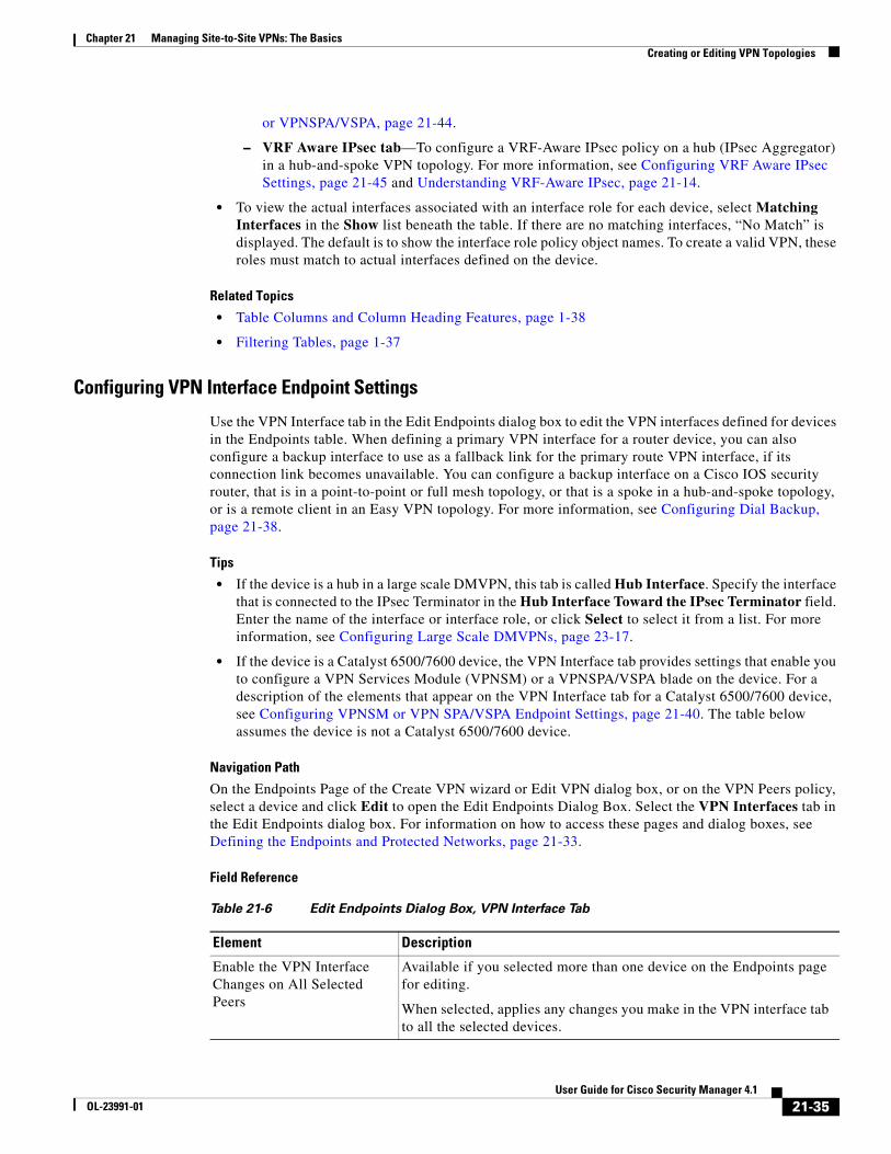
Chapter 21 Managing Site-to-Site VPNs: The BasicsCreating or Editing VPN Topologies
or VPNSPA/VSPA, page 21-44.
– VRF Aware IPsec tab—To configure a VRF-Aware IPsec policy on a hub (IPsec Aggregator) in a hub-and-spoke VPN topology. For more information, see Configuring VRF Aware IPsec Settings, page 21-45 and Understanding VRF-Aware IPsec, page 21-14.
• To view the actual interfaces associated with an interface role for each device, select Matching Interfaces in the Show list beneath the table. If there are no matching interfaces, “No Match” is displayed. The default is to show the interface role policy object names. To create a valid VPN, these roles must match to actual interfaces defined on the device.
Related Topics
• Table Columns and Column Heading Features, page 1-38
• Filtering Tables, page 1-37
Configuring VPN Interface Endpoint Settings
Use the VPN Interface tab in the Edit Endpoints dialog box to edit the VPN interfaces defined for devices in the Endpoints table. When defining a primary VPN interface for a router device, you can also configure a backup interface to use as a fallback link for the primary route VPN interface, if its connection link becomes unavailable. You can configure a backup interface on a Cisco IOS security router, that is in a point-to-point or full mesh topology, or that is a spoke in a hub-and-spoke topology, or is a remote client in an Easy VPN topology. For more information, see Configuring Dial Backup, page 21-38.
Tips
• If the device is a hub in a large scale DMVPN, this tab is called Hub Interface. Specify the interface that is connected to the IPsec Terminator in the Hub Interface Toward the IPsec Terminator field. Enter the name of the interface or interface role, or click Select to select it from a list. For more information, see Configuring Large Scale DMVPNs, page 23-17.
• If the device is a Catalyst 6500/7600 device, the VPN Interface tab provides settings that enable you to configure a VPN Services Module (VPNSM) or a VPNSPA/VSPA blade on the device. For a description of the elements that appear on the VPN Interface tab for a Catalyst 6500/7600 device, see Configuring VPNSM or VPN SPA/VSPA Endpoint Settings, page 21-40. The table below assumes the device is not a Catalyst 6500/7600 device.
Navigation Path
On the Endpoints Page of the Create VPN wizard or Edit VPN dialog box, or on the VPN Peers policy, select a device and click Edit to open the Edit Endpoints Dialog Box. Select the VPN Interfaces tab in the Edit Endpoints dialog box. For information on how to access these pages and dialog boxes, see Defining the Endpoints and Protected Networks, page 21-33.
Field Reference
Table 21-6 Edit Endpoints Dialog Box, VPN Interface Tab
Element Description
Enable the VPN Interface Changes on All Selected Peers
Available if you selected more than one device on the Endpoints page for editing.
When selected, applies any changes you make in the VPN interface tab to all the selected devices.
21-35User Guide for Cisco Security Manager 4.1
OL-23991-01

Chapter 21 Managing Site-to-Site VPNs: The BasicsCreating or Editing VPN Topologies
VPN Interface The VPN interface defined for the selected device. Enter the name of the interface role policy object that defines identifies the interface, or click Select to select it from a list or to create a new interface role object. (See Creating Interface Role Objects, page 6-57.)
If the device is an ASA 5505 version 7.2(1) or later, it must have two interfaces defined with different security levels. For more information, see Managing Device Interfaces, Hardware Ports, and Bridge Groups, page 42-13.
Connection Type Only available in a hub-and-spoke VPN topology, if the selected device is an ASA or PIX 7.0+ device, and the selected technology is Regular IPsec.
Select the type of connection that the hub or spoke will use during an SA negotiation:
• Answer Only—To configure the hub to only respond to an SA negotiation, but not initiate it. This is the default for hubs.
• Originate Only—To configure the device to only initiate an SA negotiation, but not respond to one. This is the default for spokes.
• Bidirectional—To configure the hub or spoke to both initiate and respond to an SA negotiation.
Local Peer IPSec Termination
Unavailable if the selected technology is Easy VPN.
Specifies the IP address of the VPN interface of the local router. You can select one of the following options:
• Tunnel Source IP Address—Use the IP address of the tunnel source.
• VPN Interface IP Address—Uses the configured IP address on the selected VPN interface. Only one VPN interface can match the interface role. This option is available only if you select Configure Unique Tunnel Source for each Tunnel in the GRE Modes policy.
• IP Address—Explicitly specify the IP address of the VPN interface of the local router. Use this option when the device is behind a NAT boundary to specify the NAT IP Address.
Note If you select a tunnel source as the VPN interface, it is likely that the VPN interface has a dynamically assigned IP address.
• IP Address of Another Existing Interface to be Used as Local Address (unavailable if IPsec technology is DMVPN)—To use the configured IP address on any interface as a local address, not necessarily a VPN interface. Enter the interface in the field provided.
You can choose the required interface by clicking Select. A dialog box opens that lists all available predefined interface roles, and in which you can create an interface role object.
Table 21-6 Edit Endpoints Dialog Box, VPN Interface Tab (Continued)
Element Description
21-36User Guide for Cisco Security Manager 4.1
OL-23991-01

Chapter 21 Managing Site-to-Site VPNs: The BasicsCreating or Editing VPN Topologies
Tunnel Source Available only for IPsec/GRE or DMVPN.
If you have enabled the setting to use a unique tunnel source per tunnel interface in the GRE Modes > Tunnel Parameters tab, the Override Unique Tunnel Source per Tunnel Interface check box is available. Select this option to specify a different tunnel source for the selected device.
Specifies the tunnel source address to be used by the GRE or DMVPN tunnel on the spoke side. You can select one of the following options:
• VPN Interface—Uses the VPN interface as the tunnel source address.
• Interface—To use any interface as the tunnel source address, not necessarily a VPN interface. Enter the interface name or click Select to select an interface role that identifies the interface (you can also create a role from the selection dialog box).
Dial Backup Settings
Enable Backup Available if the selected device is an IOS router that is in a point-to-point or full mesh topology, or that is a spoke in a hub-and-spoke topology, or that is a remote client in an Easy VPN topology.
Whether to configure a backup interface to use as a fallback link for the primary route VPN interface, if its connection link becomes unavailable.
Tip Before configuring a backup interface, you must first configure the dialer interface settings on the device. For more information, see Dialer Interfaces on Cisco IOS Routers, page 56-27.
Dialer Interface The logical interface through which the secondary route traffic is directed when the dialer interface is activated. This can be a Serial, Async, or BRI interface.
Enter the name of the interface or interface role object, or click Select to select it from a list.
Primary Next Hop IP Address
Available only if the selected technology is Regular IPsec, IPsec/GRE, GRE Dynamic IP, or Easy VPN.
The IP address to which the primary interface connects when it is active. This is known as the next hop IP address.
If you do not specify the next hop IP address, Security Manager configures a static route using the VPN interface name. The VPN interface must be point-to-point or deployment fails.
You can choose the required IP address by clicking Select. The Network/Hosts selector opens, in which you can select a network from which the IP address will be allocated.
Table 21-6 Edit Endpoints Dialog Box, VPN Interface Tab (Continued)
Element Description
21-37User Guide for Cisco Security Manager 4.1
OL-23991-01

Chapter 21 Managing Site-to-Site VPNs: The BasicsCreating or Editing VPN Topologies
Configuring Dial Backup
You can use dial backup to provide a fallback link for a primary, direct connection when the primary link becomes unavailable. You can configure dial backup on Cisco IOS security routers that participate in a point-to-point, Extranet, or full mesh VPN topology, or that are spokes in a hub-and-spoke topology. You can also configure it on a remote client router running IOS version 12.3(14)T+ in an Easy VPN topology.
Implementation of the dial backup feature is based on the assumption that two static routes exist:
• A primary route through a primary gateway, which has highest priority.
• A secondary route through a secondary gateway, which has lower priority and only appears in the routing table when the primary gateway is down.
Security Manager configures a logical dialer interface on the spoke. The dialer interface is associated with a physical backup interface. When the primary route is down, the dialer interface is activated and traffic is redirected through this backup interface along the secondary route. To ensure that the spoke-hub traffic is encrypted, Security Manager applies a crypto map to the dialer interface. This crypto map is identical to the crypto map on the VPN interface (the primary route interface). In Easy VPN, the backup configuration is attached to the dialer interface.
Depending on the IOS version, Response Time Reporter (RTR) or Service Level Agreement (SLA) IOS technology is used to detect loss of network performance on the primary route. If the assigned IPsec technology is DMVPN, Dialer Watch-List (DWL) is used.
ISDN Basic Rate Interface (BRI) and analog modem interfaces can be configured as backup interfaces to other primary interfaces. In such a case, an ISDN or analog modem connection is made if the primary interface goes down. Should the primary interface and connection go down, the ISDN or analog modem interface immediately dials out to establish a connection so that network services are not lost.
Before You Begin
• Configure the dialer interface settings on the Cisco IOS routers. This requires defining the relationship between the physical BRI and Async interfaces, and the virtual dialer interfaces used when configuring dial backup. For more information, see Dialer Interfaces on Cisco IOS Routers, page 56-27.
Tracking IP Address The IP address of the destination device to which connectivity must be maintained from the primary VPN interface connection. This is the device that is pinged by the Service Assurance agent through the primary route to track connectivity. The backup connection is triggered if connectivity to this device is lost.
If you do not specify an IP address, the primary hub VPN interface is used in a hub-and-spoke or Easy VPN topology. In a point-to-point or full mesh VPN topology, the peer VPN interface is used.
You can choose the required IP address by clicking Select. The Network/Hosts selector opens, in which you can select a network from which the IP address will be allocated.
Advanced button Available if the selected technology is Regular IPsec, IPsec/GRE, GRE Dynamic IP, or Easy VPN.
Click this button to configure additional optional settings using the Dial Backup Settings Dialog Box, page 21-39.
Table 21-6 Edit Endpoints Dialog Box, VPN Interface Tab (Continued)
Element Description
21-38User Guide for Cisco Security Manager 4.1
OL-23991-01

Chapter 21 Managing Site-to-Site VPNs: The BasicsCreating or Editing VPN Topologies
• Make sure that the primary route is functioning.
• For Extranet VPNs, you can configure dial backup on the local (managed) device only.
Step 1 For most VPN topologies, you configure dial backup when creating or editing a site-to-site VPN. You can also edit the Peers policy for existing VPN topologies. For Extranet VPNs, you configure dial backup through the Peers policy only.
Do one of the following:
• In the Create VPN wizard, proceed to the Endpoints page (see Creating or Editing VPN Topologies, page 21-28 and Defining the Endpoints and Protected Networks, page 21-33).
• In the Edit VPN dialog box, click the Endpoints tab (see Creating or Editing VPN Topologies, page 21-28 and Defining the Endpoints and Protected Networks, page 21-33).
• For Extranet VPNs, or for editing any other VPN topology, select the Peers policy. For general information on editing endpoints, see Defining the Endpoints and Protected Networks, page 21-33.
Step 2 Select the router on which you want to configure dial backup and click the Edit (pencil) button. If there is more than one router that will have the same dialer configuration, you can select and edit them all at once.
This action opens the Edit Endpoints dialog box. Select the VPN Interface tab if it is not already selected.
Step 3 On the VPN Interface tab, configure the following options related to dial backup. If you are creating a new VPN, you need to configure the other settings (such as VPN interface) as well. For detailed reference information for these options, see Configuring VPN Interface Endpoint Settings, page 21-35.
• Enable Backup—Select this option.
• Dialer Interface—Specify the physical interface through which the secondary route traffic will be directed when the logical dialer interface is activated.
• Primary Next Hop IP Address—If the selected IPsec technology is Regular IPsec, IPsec/GRE, GRE Dynamic IP, or Easy VPN, enter the next hop IP address. If you do not enter the next hop IP address, Security Manager configures a static route using the interface name.
• Tracking IP Address—Specify the IP address of the destination device to which connectivity must be maintained from the primary VPN interface connection. This is the device that is pinged through the primary route to track connectivity. The backup connection is triggered if connectivity to this device is lost.
If you do not specify an IP address, the primary hub VPN interface is used in a hub-and-spoke or Easy VPN topology. In a point-to-point or full mesh VPN topology, the peer VPN interface is used.
Step 4 If the selected IPsec technology is Regular IPsec, IPsec/GRE, GRE Dynamic IP, or Easy VPN, click Advanced to configure additional (optional) settings in the Dial Backup Settings dialog box. These settings are explained in Dial Backup Settings Dialog Box, page 21-39. Click OK to save your changes.
Step 5 Click OK in the Edit Endpoints dialog box.
Dial Backup Settings Dialog Box
Use the Dial Backup Settings dialog box to define optional settings for configuring a dial backup policy for your site-to-site VPN. These settings are available for Regular IPsec, IPsec/GRE, GRE Dynamic IP, or Easy VPN technologies.
21-39User Guide for Cisco Security Manager 4.1
OL-23991-01
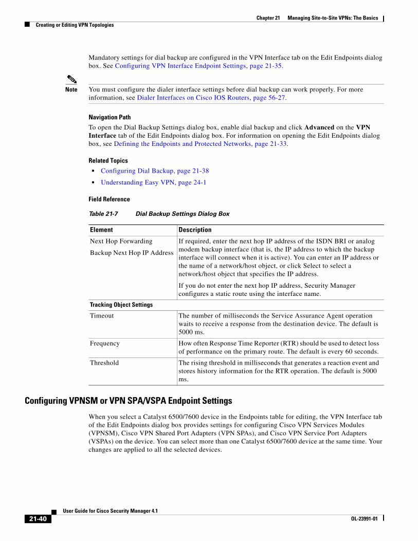
Chapter 21 Managing Site-to-Site VPNs: The BasicsCreating or Editing VPN Topologies
Mandatory settings for dial backup are configured in the VPN Interface tab on the Edit Endpoints dialog box. See Configuring VPN Interface Endpoint Settings, page 21-35.
Note You must configure the dialer interface settings before dial backup can work properly. For more information, see Dialer Interfaces on Cisco IOS Routers, page 56-27.
Navigation Path
To open the Dial Backup Settings dialog box, enable dial backup and click Advanced on the VPN Interface tab of the Edit Endpoints dialog box. For information on opening the Edit Endpoints dialog box, see Defining the Endpoints and Protected Networks, page 21-33.
Related Topics
• Configuring Dial Backup, page 21-38
• Understanding Easy VPN, page 24-1
Field Reference
Configuring VPNSM or VPN SPA/VSPA Endpoint Settings
When you select a Catalyst 6500/7600 device in the Endpoints table for editing, the VPN Interface tab of the Edit Endpoints dialog box provides settings for configuring Cisco VPN Services Modules (VPNSM), Cisco VPN Shared Port Adapters (VPN SPAs), and Cisco VPN Service Port Adapters (VSPAs) on the device. You can select more than one Catalyst 6500/7600 device at the same time. Your changes are applied to all the selected devices.
Table 21-7 Dial Backup Settings Dialog Box
Element Description
Next Hop Forwarding
Backup Next Hop IP Address
If required, enter the next hop IP address of the ISDN BRI or analog modem backup interface (that is, the IP address to which the backup interface will connect when it is active). You can enter an IP address or the name of a network/host object, or click Select to select a network/host object that specifies the IP address.
If you do not enter the next hop IP address, Security Manager configures a static route using the interface name.
Tracking Object Settings
Timeout The number of milliseconds the Service Assurance Agent operation waits to receive a response from the destination device. The default is 5000 ms.
Frequency How often Response Time Reporter (RTR) should be used to detect loss of performance on the primary route. The default is every 60 seconds.
Threshold The rising threshold in milliseconds that generates a reaction event and stores history information for the RTR operation. The default is 5000 ms.
21-40User Guide for Cisco Security Manager 4.1
OL-23991-01

Chapter 21 Managing Site-to-Site VPNs: The BasicsCreating or Editing VPN Topologies
The device can be in a point-to-point or full mesh VPN topology, or a hub or spoke in a hub-and-spoke VPN topology managed by Security Manager (except in an Easy VPN configuration, where the device cannot be a spoke). These settings must also be configured if the selected device is an IPsec Terminator in a large scale DMVPN, although not all settings described below are available. See Configuring Large Scale DMVPNs, page 23-17.
General Notes
• A Catalyst 6500/7600 device can contain from 3 to 13 chassis slots. Due to the design of the blades, you can install one VPNSM or two VPNSPA/VSPA per slot. The location of a VPNSPA/VSPA is identified with a slot and subslot number. Security Manager stores this information in its inventory, so that Security Manager can manage the VPN topologies.
• If you are configuring intra-chassis high availability, you cannot use a VPNSM blade and a VPNSPA/VSPA blade on the same device as primary and failover blades.
• In a remote access VPN, you can configure only one failover unit for each IPsec proposal. See VPNSM/VPN SPA/VSPA Settings Dialog Box, page 29-6.
• If the Catalyst 6500/7600 has a Firewall Services Module (FWSM), you can configure it to work with these modules. For more information, see Configuring a Firewall Services Module (FWSM) Interface with VPNSM or VPNSPA/VSPA, page 21-44.
• If you are configuring a VPNSM or VPNSPA/VSPA with VRF-Aware IPsec on a device, the device cannot belong to a different VPN topology in which VRF-Aware IPsec is not configured. For more information, see Configuring VRF Aware IPsec Settings, page 21-45.
• Create an inside VLAN on the Catalyst 6500/7600 device, or edit an existing port or VLAN configuration. If the device is configured with VRF-Aware IPsec, you must create a forwarding VLAN.
Notes for VPNSMs
• Security Manager supports the configuration of multiple VPNSMs on a Catalyst 6500/7600 device, but only one module (or two if you are configuring intra chassis high availability) can be configured per VPN topology.
• VPNSM configuration requires that its parent Catalyst 6500/7600 device is running Cisco IOS Software release 12.2(18)SXD1 and later.
• You can use only Layer 3 VLANs for VPNSM configuration.
Notes for VPNSPA/VSPAs
• This configuration also applies if you are configuring an IPsec Terminator in a large scale DMVPN configuration. For more information, see Configuring Large Scale DMVPNs, page 23-17.
• The VPN SPA supports the AES encryption algorithm for all key sizes (128-, 192-, and 256-bit), as well as the DES and 3DES encryption algorithms. For more information, see Deciding Which Encryption Algorithm to Use, page 22-6.
In VRF mode, the crypto engine slot slot/subslot {inside | outside} command is deployed on the inside and outside VPN interfaces.
• Make sure that the Catalyst 6500/7600 device is running Cisco IOS Software release 12.2(18)SXE2 or later.
• If you plan to use Crypto Connect Alternate mode (whereby encrypted traffic entering the VPNSM/VPN SPA is passed through and clear text traffic is bypassed), the Catalyst 6500 device must be running Cisco IOS Software version 12.2(33)SXH or later, and the 7600 router must be running 12.2(33)SRA or later.
21-41User Guide for Cisco Security Manager 4.1
OL-23991-01

Chapter 21 Managing Site-to-Site VPNs: The BasicsCreating or Editing VPN Topologies
• In the case of a DMVPN topology in which multiple hubs participate, if one hub is configured with a VPN SPA blade, a tunnel key must not be configured on any of the devices, whether they are spokes or hubs. Devices that participate in such a topology must be running Cisco IOS Software version 12.3T and later in order to support tunnels without keys.
Navigation Path
On the Endpoints Page of the Create VPN wizard or Edit VPN dialog box, or on the VPN Peers policy, select a Catalyst 6500/7600 device, then click Edit to open the Edit Endpoints Dialog Box. Select the FWSM tab in the Edit Endpoints dialog box. For information on how to access these pages and dialog boxes, see Defining the Endpoints and Protected Networks, page 21-33.
Field Reference
Table 21-8 Edit Endpoints Dialog Box, VPN Interface Tab’s VPNSM/VPN SPA/VSPA Settings
Element Description
Enable the VPN Interface Changes on All Selected Peers
Note Available if you selected more than one Catalyst 6500/7600 device for editing in the Endpoints page.
When selected, applies any changes you make in the VPN interface tab to all the selected devices.
VPNSM/VPN SPA/VSPA Settings
• Use Crypto Connect Alternate—When selected, only encrypted traffic entering the VPNSM/VPN SPA on the Catalyst 6500/7600 is passed through. Clear text traffic does not go through (bypasses) the adapters. To use this option, the Catalyst 6500 must be running version 12.2(33)SXH or later, and the 7600 router must be running 12.2(33)SRA or later.
This mode is recommended as an alternate to Crypto connect mode for enterprise customers who have a need to support large VPN topologies (financial institutions, for example) or need to pass large amounts of data over an encrypted channel (remote disaster recovery or backup over the Internet).
• Inside VLAN—The VLAN that serves as the inside interface to the service module or adapter. It is also the hub endpoint of the VPN tunnel (unless VRF-Aware IPsec is configured on the device). Enter the name of the VLAN or interface role object, or click Select to select it from a list.
• Slot and Subslot—The number designating the slot location of the VPNSM or VPNSPA/VSPA. If you are configuring a VPNSPA/VSPA, the subslot number is also required.
• Outside VLAN/External port—The external port or VLAN that connects to the inside VLAN. Enter the name of the VLAN or interface role object, or click Select to select it from a list. You must select an interface or interface role that differs from the one selected for the inside VLAN.
Note If VRF-Aware IPsec is configured on the device, the external port or VLAN must have an IP address.
21-42User Guide for Cisco Security Manager 4.1
OL-23991-01

Chapter 21 Managing Site-to-Site VPNs: The BasicsCreating or Editing VPN Topologies
Tunnel Source Note Available only for a hub when the selected technology is IPsec/GRE or DMVPN.
Specifies the tunnel source address to be used by the GRE or DMVPN tunnel on the spoke side. You can select one of the following options:
• Override Unique Tunnel Source per Tunnel Interface—If you have enabled the setting to use a unique tunnel source per tunnel interface in the GRE Modes > Tunnel Parameters tab, this option is available. Select this option to specify a different tunnel source for the selected device.
• Outside VLAN/External Port (When CCA/VRF is Enabled)—When the Use Crypto Connect Alternate check box is selected, this radio button is available. When selected, specifies the outside VLAN/external port as the tunnel source.
• Inside VLAN—When selected, uses the interface configured for the inside VLAN as the tunnel source.
• Interface—To use any interface as the tunnel source address, not necessarily a VPN interface, enter the interface name or click Select to select an interface role that identifies the interface. You can create new roles from the selection list.
Local Peer IPSec Termination
Define the IPSec termination point of the VPN interface on the local router:
• Inside VLAN—Use the interface configured as the inside VLAN.
• IP Address—Use the IP address of the VPN interface on the local router. Enter the IP address.
Note If you select a tunnel source as the VPN interface, it is likely that the VPN interface has a dynamically assigned IP address.
Enable Failover Blade Whether to configure a failover VPNSM or VPNSPA/VSPA blade for intra-chassis high availability.
Note A VPNSM and VPNSPA/VSPA blade cannot be used on the same device as primary and failover blades.
Specify the failover blade, as follows:
• Slot—The slot number that identifies where the VPNSM blade or VPNSPA/VSPA blade is located.
• Subslot—If you are configuring a VPNSPA/VSPA, select the number of the subslot (0 or 1) on which the failover VPN SPA blade is installed.
Note If you are configuring a VPNSM, select the blank option.
Table 21-8 Edit Endpoints Dialog Box, VPN Interface Tab’s VPNSM/VPN SPA/VSPA Settings
Element Description
21-43User Guide for Cisco Security Manager 4.1
OL-23991-01
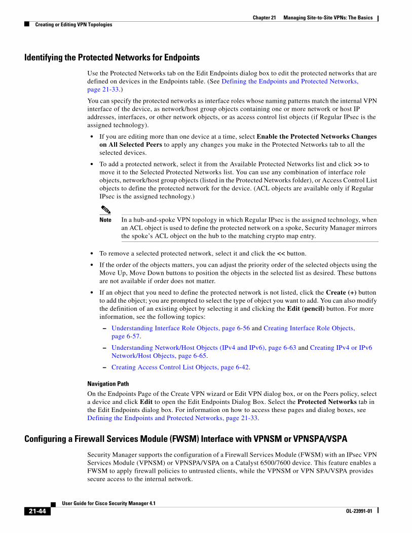
Chapter 21 Managing Site-to-Site VPNs: The BasicsCreating or Editing VPN Topologies
Identifying the Protected Networks for Endpoints
Use the Protected Networks tab on the Edit Endpoints dialog box to edit the protected networks that are defined on devices in the Endpoints table. (See Defining the Endpoints and Protected Networks, page 21-33.)
You can specify the protected networks as interface roles whose naming patterns match the internal VPN interface of the device, as network/host group objects containing one or more network or host IP addresses, interfaces, or other network objects, or as access control list objects (if Regular IPsec is the assigned technology).
• If you are editing more than one device at a time, select Enable the Protected Networks Changes on All Selected Peers to apply any changes you make in the Protected Networks tab to all the selected devices.
• To add a protected network, select it from the Available Protected Networks list and click >> to move it to the Selected Protected Networks list. You can use any combination of interface role objects, network/host group objects (listed in the Protected Networks folder), or Access Control List objects to define the protected network for the device. (ACL objects are available only if Regular IPsec is the assigned technology.)
Note In a hub-and-spoke VPN topology in which Regular IPsec is the assigned technology, when an ACL object is used to define the protected network on a spoke, Security Manager mirrors the spoke’s ACL object on the hub to the matching crypto map entry.
• To remove a selected protected network, select it and click the << button.
• If the order of the objects matters, you can adjust the priority order of the selected objects using the Move Up, Move Down buttons to position the objects in the selected list as desired. These buttons are not available if order does not matter.
• If an object that you need to define the protected network is not listed, click the Create (+) button to add the object; you are prompted to select the type of object you want to add. You can also modify the definition of an existing object by selecting it and clicking the Edit (pencil) button. For more information, see the following topics:
– Understanding Interface Role Objects, page 6-56 and Creating Interface Role Objects, page 6-57.
– Understanding Network/Host Objects (IPv4 and IPv6), page 6-63 and Creating IPv4 or IPv6 Network/Host Objects, page 6-65.
– Creating Access Control List Objects, page 6-42.
Navigation Path
On the Endpoints Page of the Create VPN wizard or Edit VPN dialog box, or on the Peers policy, select a device and click Edit to open the Edit Endpoints Dialog Box. Select the Protected Networks tab in the Edit Endpoints dialog box. For information on how to access these pages and dialog boxes, see Defining the Endpoints and Protected Networks, page 21-33.
Configuring a Firewall Services Module (FWSM) Interface with VPNSM or VPNSPA/VSPA
Security Manager supports the configuration of a Firewall Services Module (FWSM) with an IPsec VPN Services Module (VPNSM) or VPNSPA/VSPA on a Catalyst 6500/7600 device. This feature enables a FWSM to apply firewall policies to untrusted clients, while the VPNSM or VPN SPA/VSPA provides secure access to the internal network.
21-44User Guide for Cisco Security Manager 4.1
OL-23991-01
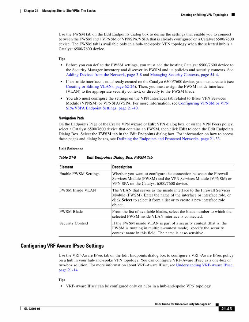
Chapter 21 Managing Site-to-Site VPNs: The BasicsCreating or Editing VPN Topologies
Use the FWSM tab on the Edit Endpoints dialog box to define the settings that enable you to connect between the FWSM and a VPNSM or VPNSPA/VSPA that is already configured on a Catalyst 6500/7600 device. The FWSM tab is available only in a hub-and-spoke VPN topology when the selected hub is a Catalyst 6500/7600 device.
Tips
• Before you can define the FWSM settings, you must add the hosting Catalyst 6500/7600 device to the Security Manager inventory and discover its FWSM and its policies and security contexts. See Adding Devices from the Network, page 3-8 and Managing Security Contexts, page 54-4.
• If an inside interface is not already created on the Catalyst 6500/7600 device, you must create it (see Creating or Editing VLANs, page 62-26). Then, you must assign the FWSM inside interface (VLAN) to the appropriate security context, or directly to the FWSM blade.
• You also must configure the settings on the VPN Interfaces tab related to IPsec VPN Services Module (VPNSM) or VPNSPA/VSPA. For more information, see Configuring VPNSM or VPN SPA/VSPA Endpoint Settings, page 21-40.
Navigation Path
On the Endpoints Page of the Create VPN wizard or Edit VPN dialog box, or on the VPN Peers policy, select a Catalyst 6500/7600 device that contains an FWSM, then click Edit to open the Edit Endpoints Dialog Box. Select the FWSM tab in the Edit Endpoints dialog box. For information on how to access these pages and dialog boxes, see Defining the Endpoints and Protected Networks, page 21-33.
Field Reference
Configuring VRF Aware IPsec Settings
Use the VRF-Aware IPsec tab on the Edit Endpoints dialog box to configure a VRF-Aware IPsec policy on a hub in your hub-and-spoke VPN topology. You can configure VRF-Aware IPsec as a one-box or two-box solution. For more information about VRF-Aware IPsec, see Understanding VRF-Aware IPsec, page 21-14.
Tips
• VRF-Aware IPsec can be configured only on hubs in a hub-and-spoke VPN topology.
Table 21-9 Edit Endpoints Dialog Box, FWSM Tab
Element Description
Enable FWSM Settings Whether you want to configure the connection between the Firewall Services Module (FWSM) and the VPN Services Module (VPNSM) or VPN SPA on the Catalyst 6500/7600 device.
FWSM Inside VLAN The VLAN that serves as the inside interface to the Firewall Services Module (FWSM). Enter the name of the interface or interface role, or click Select to select it from a list or to create a new interface role object.
FWSM Blade From the list of available blades, select the blade number to which the selected FWSM inside VLAN interface is connected.
Security Context If the FWSM inside VLAN is part of a security context (that is, the FWSM is running in multiple-context mode), specify the security context name in this field. The name is case-sensitive.
21-45User Guide for Cisco Security Manager 4.1
OL-23991-01

Chapter 21 Managing Site-to-Site VPNs: The BasicsCreating or Editing VPN Topologies
• In a VPN topology with two hubs, you must configure VRF-Aware IPsec on both devices.
• You cannot configure VRF-Aware IPsec on a device that belongs to another VPN topology in which VRF-Aware IPsec is not configured.
• You cannot configure VRF-Aware IPsec on hubs that have been configured with high availability. See Configuring High Availability in Your VPN Topology, page 21-48.
• Deployment might fail if the IPsec Aggregator is configured with the same keyring CLI command as the existing preshared key (keyring) command, and is not referenced by any other command. In this case, Security Manager does not use the VRF keyring CLI, but generates the keyring with a different name, causing deployment to fail. You must manually remove the preshared key keyring command through the CLI before you can deploy the configuration.
Navigation Path
On the Endpoints Page of the Create VPN wizard or Edit VPN dialog box, or on the VPN Peers policy, select a device that supports VRF-Aware IPsec configuration in a hub-and-spoke topology, and click Edit to open the Edit Endpoints Dialog Box. Select the VRF-Aware IPsec tab in the Edit Endpoints dialog box. For information on how to access these pages and dialog boxes, see Defining the Endpoints and Protected Networks, page 21-33 and Creating or Editing VPN Topologies, page 21-28.
Field Reference
Table 21-10 Edit Endpoints Dialog Box, VRF Aware IPsec Tab
Element Description
Enable the VRF Settings Changes on All Selected Peers
Available if you selected more than one device for editing in the Endpoints page.
When selected, applies any changes you make in the VRF Settings tab to all the selected devices.
Enable VRF Settings Whether to enable the configuration of VRF settings on the device.
Note You can remove VRF settings that were defined for the VPN topology by deselect this check box. However, if VRF-Aware IPsec is configured on a Catalyst 6500/7600 device, disabling it requires additional steps, as explained in Enabling and Disabling VRF on Catalyst Switches and 7600 Devices, page 21-17.
VRF Solution The type of VRF solution you want to configure:
• 1-Box (IPsec Aggregator + MPLS PE)—In the one-box solution, one device serves as the Provider Edge (PE) router that does the MPLS tagging of the packets in addition to IPsec encryption and decryption from the Customer Edge (CE) devices. For more information, see VRF-Aware IPsec One-Box Solution, page 21-14.
• 2-Box (IPsec Aggregator Only)—In the two-box solution, the PE device does just the MPLS tagging, while the IPsec Aggregator device does the IPsec encryption and decryption from the CEs. For more information, see VRF-Aware IPsec Two-Box Solution, page 21-15.
VRF Name The name of the VRF routing table on the IPsec Aggregator. The VRF name is case-sensitive.
21-46User Guide for Cisco Security Manager 4.1
OL-23991-01

Chapter 21 Managing Site-to-Site VPNs: The BasicsCreating or Editing VPN Topologies
Route Distinguisher The unique identifier of the VRF routing table on the IPsec Aggregator. This unique route distinguisher maintains the routing separation for each VPN across the MPLS core to the other PE routers.
The identifier can be in either of the following formats:
• IP address:X (where X is in the range 0- 2147483647).
• N:X (where N is in the range 0-65535, and X is in the range 0- 2147483647).
Note You cannot override the RD identifier after deploying the VRF configuration to your device. To modify the RD identifier after deployment, you must manually remove it using the device CLI, and then deploy again.
Interface Towards Provider Edge
(2-Box solution only.)
The VRF forwarding interface on the IPsec Aggregator towards the PE device. If the IPsec Aggregator (hub) is a Catalyst VPN service module, you must specify a VLAN.
Enter the name of the interface or interface role object, or click Select to select it from a list or to create a new interface role object.
Routing Protocol
(2-Box solution only.)
The routing protocol to be used between the IPsec Aggregator and the PE. The options are BGP, EIGRP, OSPF, RIPv2, or Static route. The default is BGP.
If the routing protocol used for the secured IGP differs from the routing protocol between the IPsec Aggregator and the PE, select the routing protocol to use for redistributing the routing to the secured IGP.
For information about protocols, see Chapter 55, “Managing Routers”.
Note In a one-box solution, these fields are unavailable as you do not need to specify the routing protocol and AS number. In the one-box solution, only the BGP protocol is supported.
AS Number
(2-Box solution, BGP or EIGRP routing only.)
The number that will be used to identify the autonomous system (AS) area between the IPsec Aggregator and the PE. The AS number must be within the range 1-65535.
If the routing protocol used for the secured IGP differs from the routing protocol between the IPsec Aggregator and the PE, enter an AS number that will be used to identify the secured IGP into which the routing will be redistributed from the IPsec Aggregator and the PE. This is relevant only when IPsec/GRE or DMVPN are applied.
Process Number
(2-Box solution, OSPF routing only.)
The routing process ID number that will be used to identify the secured IGP if you are using OSPF routing.
The range is 1-65535.
OSPF Area ID
(2-Box solution, OSPF routing only.)
The ID number of the area in which the packet belongs. You can enter any number from 0-4294967295.
Note All OSPF packets are associated with a single area, so all devices must have the same area ID number.
Table 21-10 Edit Endpoints Dialog Box, VRF Aware IPsec Tab (Continued)
Element Description
21-47User Guide for Cisco Security Manager 4.1
OL-23991-01
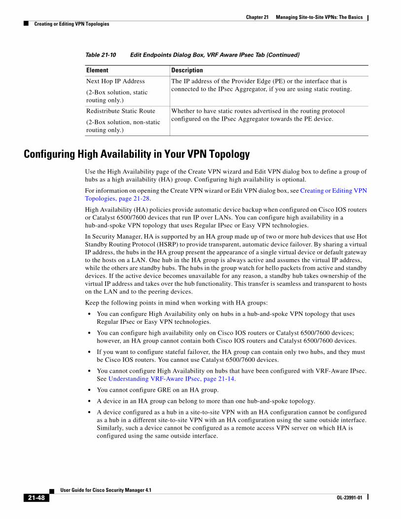
Chapter 21 Managing Site-to-Site VPNs: The BasicsCreating or Editing VPN Topologies
Configuring High Availability in Your VPN TopologyUse the High Availability page of the Create VPN wizard and Edit VPN dialog box to define a group of hubs as a high availability (HA) group. Configuring high availability is optional.
For information on opening the Create VPN wizard or Edit VPN dialog box, see Creating or Editing VPN Topologies, page 21-28.
High Availability (HA) policies provide automatic device backup when configured on Cisco IOS routers or Catalyst 6500/7600 devices that run IP over LANs. You can configure high availability in a hub-and-spoke VPN topology that uses Regular IPsec or Easy VPN technologies.
In Security Manager, HA is supported by an HA group made up of two or more hub devices that use Hot Standby Routing Protocol (HSRP) to provide transparent, automatic device failover. By sharing a virtual IP address, the hubs in the HA group present the appearance of a single virtual device or default gateway to the hosts on a LAN. One hub in the HA group is always active and assumes the virtual IP address, while the others are standby hubs. The hubs in the group watch for hello packets from active and standby devices. If the active device becomes unavailable for any reason, a standby hub takes ownership of the virtual IP address and takes over the hub functionality. This transfer is seamless and transparent to hosts on the LAN and to the peering devices.
Keep the following points in mind when working with HA groups:
• You can configure High Availability only on hubs in a hub-and-spoke VPN topology that uses Regular IPsec or Easy VPN technologies.
• You can configure high availability only on Cisco IOS routers or Catalyst 6500/7600 devices; however, an HA group cannot contain both Cisco IOS routers and Catalyst 6500/7600 devices.
• If you want to configure stateful failover, the HA group can contain only two hubs, and they must be Cisco IOS routers. You cannot use Catalyst 6500/7600 devices.
• You cannot configure High Availability on hubs that have been configured with VRF-Aware IPsec. See Understanding VRF-Aware IPsec, page 21-14.
• You cannot configure GRE on an HA group.
• A device in an HA group can belong to more than one hub-and-spoke topology.
• A device configured as a hub in a site-to-site VPN with an HA configuration cannot be configured as a hub in a different site-to-site VPN with an HA configuration using the same outside interface. Similarly, such a device cannot be configured as a remote access VPN server on which HA is configured using the same outside interface.
Next Hop IP Address
(2-Box solution, static routing only.)
The IP address of the Provider Edge (PE) or the interface that is connected to the IPsec Aggregator, if you are using static routing.
Redistribute Static Route
(2-Box solution, non-static routing only.)
Whether to have static routes advertised in the routing protocol configured on the IPsec Aggregator towards the PE device.
Table 21-10 Edit Endpoints Dialog Box, VRF Aware IPsec Tab (Continued)
Element Description
21-48User Guide for Cisco Security Manager 4.1
OL-23991-01

Chapter 21 Managing Site-to-Site VPNs: The BasicsCreating or Editing VPN Topologies
• The same auto-generated preshared key must be used for authentication on all peers. If you specified not to use this option when configuring a preshared key policy, this is overridden during configuration of High Availability. For more information, see Configuring IKEv1 Preshared Key Policies, page 22-40.
• During generation of configurations, all hubs in the HA group receive the same commands, which must be deployed to the HA group as a unit. You cannot deploy to individual hubs in the group.
The following table describes the options for configuring high availability.
Table 21-11 High Availability Page
Element Description
Enable Whether to enable high availability configuration on a group of hubs. If you already configured high availability, you can remove the configuration by deselecting this option.
Inside Virtual IP The IP address that is shared by the hubs in the HA group and that represents the inside interface of the HA group. The virtual IP address must be on the same subnet as the inside interfaces of the hubs in the HA group, but must not be identical to the IP address of any of these interfaces.
Note If there is an existing standby group on the device, make sure that the IP address you provide is different from the virtual IP address already configured on the device.
Inside Mask The subnet mask for the inside virtual IP address.
VPN Virtual IP The IP address that is shared by the hubs in the HA group and represents the VPN interface of the HA group. This IP address serves as the hub endpoint of the VPN tunnel.
Note If there is an existing standby group on the device, make sure that the IP address you provide is different from the virtual IP address already configured on the device.
VPN Mask The subnet mask for the VPN virtual IP address.
Hello Interval The duration in seconds (within the range of 1-254) between each hello message sent by a hub to the other hubs in the group to indicate status and priority. The default is 5 seconds.
Hold Time The duration in seconds (within the range of 2-255) that a standby hub will wait to receive a hello message from the active hub before concluding that the hub is down. The default is 15 seconds.
Standby Group Number (Inside)
The standby number of the inside hub interface that matches the internal virtual IP subnet for the hubs in the HA group. The number must be within the range of 0-255. The default is 1.
Standby Group Number (Outside)
The standby number of the outside hub interface that matches the external virtual IP subnet for the hubs in the HA group. The number must be within the range of 0-255. The default is 2.
Note The outside standby group number must be different from the inside standby group number.
21-49User Guide for Cisco Security Manager 4.1
OL-23991-01

Chapter 21 Managing Site-to-Site VPNs: The BasicsCreating or Editing VPN Topologies
Related Topics
• Hub-and-Spoke VPN Topologies, page 21-2
• Understanding Easy VPN, page 24-1
Defining GET VPN Group EncryptionUse the GET VPN Group Encryption page to define the group settings and security associations for a GET VPN topology.
The contents of this page differ depending on whether you are using the Create VPN wizard or you are editing the Group Encryption Policy. The wizard page is not tabbed, whereas the policy is tabbed. There is an extra field on the wizard page to allow the security association configuration.
To open the GET VPN Group Encryption page:
• When creating a new GET VPN, use the Create VPN wizard. For information on starting the wizard, see Creating or Editing VPN Topologies, page 21-28.
• (Site-to-Site VPN Manager Window) Select an existing GET VPN topology and then select Group Encryption Policy in the Policies selector.
• (Policy view) Select Site-to-Site VPN > Group Encryption Policy, and then select an existing policy or create a new one.
The following table describes the options you can configure when defining the GET VPN group encryption settings.
Enable Stateful Failover Whether to enable stateful failover, which uses Stateful SwitchOver (SSO) to ensure that state information is shared between the HSRP devices in the HA group. If a device fails, the shared state information enables the standby device to maintain IPsec sessions without having to re-establish the tunnel or renegotiate the security associations.
You can configure stateful failover only on an HA group that contains two hubs that are Cisco IOS routers. This check box is disabled if the HA group contains more than two hubs.
In an Easy VPN topology, this check box appears selected and disabled, as stateful failover must always be configured.
Tips:
• When deselected in a Regular IPsec topology, stateless failover is configured on the HA group. Stateless failover will also be configured if the HA group contains more than two hubs. You can configure stateless failover on Cisco IOS routers or Catalyst 6500/7600 devices.
• Stateful failover cannot be used when RSA Signature is the IKE authentication method.
• Stateful failover can be configured together with PKI configuration, but only on devices with Cisco IOS version 12.3(14)T and later.
Table 21-11 High Availability Page (Continued)
Element Description
21-50User Guide for Cisco Security Manager 4.1
OL-23991-01

Chapter 21 Managing Site-to-Site VPNs: The BasicsCreating or Editing VPN Topologies
Table 21-12 GET VPN Group Encryption Policy Page
Element Description
Group Settings Tab
Group Name The name of the Group Name of Interpretation (GDOI) group. This name is the same as a VPN name.
Group Identity A parameter that is used to identify the group. All key servers and group members use this parameter to identify with the group.
The identity can be either a number (such as 3333) or any IP address (such as the multicast address used for rekey).
Receive Only If enabled, group members decrypt traffic and forward it in clear text. This feature is useful for testing the VPN. In normal operation, ensure that this option is not selected. For detailed information, see Using Passive Mode to Migrate to GET VPN, page 25-23.
Security Policy
(Create VPN wizard only.)
An ACL policy object to be used as the security policy. For a detailed explanation of the contents of this object and how it relates to the group member security policy, see Understanding the GET VPN Security Policy and Security Associations, page 25-10.
This field appears only if you are using the Create VPN wizard. In the Group Encryption Policy, you configure the security policy on the Security Associations tab (described below).
Note If you are using multicast as the method to distribute the keys, then the ACL policy object must contain a deny rule (ACE) for the multicast address. In this way, the rekey packets sent using multicast will not be encrypted by the TEK. This statement allows the group members to receive rekey packets sent using the multicast protocol.
Authorization Type The type of authorization mechanism used by the group: None, Certificates, or Preshared Key. Selecting Certificates or Preshared Key provides additional security in allowing only authorized group members to register with the key server. This type of additional security is required when a key server serves multiple GDOI groups.
If you select Certificates, you must create a list of certificate filters (using some combination of distinguished name or full-qualified domain name attributes). This filter, located on the key server, specifies the attributes and values used to validate whether the group member is authorized to join the GDOI group. Enter a name for the certificate filter, click the Add Row (+) button, and fill in the Add Certificate Filter Dialog Box, page 21-53.
Note To configure certificate authorization, you must also configure a Public Key Infrastructure (PKI) policy for the GET VPN. The PKI enrollment object that you use should define the same distinguished names, or include the device’s fully-qualified domain name, as appropriate.
If you select Preshared Key, also select an ACL policy object to identify the authorized group members. Use permit rules to identify the host or network addresses of group members.
21-51User Guide for Cisco Security Manager 4.1
OL-23991-01

Chapter 21 Managing Site-to-Site VPNs: The BasicsCreating or Editing VPN Topologies
Key Distribution The transport method to be used to distribute keys to each group member, either unicast or multicast. For help deciding which to use, see Choosing the Rekey Transport Mechanism, page 25-6.
If you select unicast, the key server sends a rekey message to each registered group member and waits for an acknowledgment. If you select multicast, the key server sends a rekey message to all group members at once and does not wait for acknowledgment. Rekey messages are retransmitted after the retransmit interval configured in this policy.
If you select multicast, make sure that the router used as the key server is multicast enabled, and also configure the following options:
• Group IP Address—The IP address of the multicast group to be used for key distribution.
• Use Static IGMP Joins on Group Members—If you select this option, the static Source Specific Multicast (SSM) mappings are enabled, which reveal the source of multicast traffic to the group member. In the case of GET VPN, the group member learns the key server address.
RSA Key Label The label for the RSA key, which is used to encrypt a variety of messages. This key can either already exist on the device, or it can be an unused new label.
If you are creating a new VPN, you are asked at the end of the Create VPN wizard whether you want this key synchronized among the key servers; if you click Yes, Security Manager generates the key if it does not already exist. If you change this value for an existing GET VPN, you need to synchronize keys from the Key Servers policy. For more detailed information about how this key is used, and the key generation and synchronization process, see Generating and Synchronizing RSA Keys, page 25-13.
Lifetime (KEK) The number of seconds that the key encryption key (KEK) is valid. This key is used for encrypting rekey messages. Before the end of this lifetime, the key server sends rekey messages to the group, which includes a new KEK encryption key and transforms and new TEK encryption keys and transforms.
The KEK lifetime value should be greater than the TEK lifetime value (it is recommended that the KEK lifetime value be at least three times greater than the TEK lifetime value). The default value of 86,400 seconds is usually appropriate. The TEK lifetime value is configured for each security association (see Add New or Edit Security Association Dialog Box, page 21-54).
Encryption Algorithm The algorithm used to encrypt the rekey message from the key server to the group member.
Retransmits The number of times the rekey message can be sent if one or more group members do not receive it.
Interval The number of seconds between retries.
Table 21-12 GET VPN Group Encryption Policy Page (Continued)
Element Description
21-52User Guide for Cisco Security Manager 4.1
OL-23991-01

Chapter 21 Managing Site-to-Site VPNs: The BasicsCreating or Editing VPN Topologies
Related Topics
• Understanding the GET VPN Registration Process, page 25-4
• Understanding Group Encrypted Transport (GET) VPNs, page 25-2
• Configuring GET VPN, page 25-12
Add Certificate Filter Dialog Box
Use the Add Certificate Filter dialog box to define a certificate filter for the group encryption policy for GET VPNs. This filter, located on the key server, specifies the attributes and values used to validate whether the group member is authorized to join the group.
Select one of the following filter types:
• dn—(Distinguished name.) Specify a comma separated list of name=value pairs in the Subject field. For example, OU=Cisco, C=US. When you configure the Public Key Infrastructure policy, the PKI enrollment object you select should define the same values on the Certificate Subject Name tab (see PKI Enrollment Dialog Box—Certificate Subject Name Tab, page 22-57). Using a distinguished name can let you match multiple devices with a single filter.
• fqdn—(Fully-qualified domain name.) Specify the fully qualified domain name of a single device (for example, router1.example.com) in the Domain Name field. When you configure the Public Key Infrastructure policy, the PKI enrollment object you select should have the Include Device’s FQDN option selected. Because each device has a unique name, an FQDN filter matches a single device only.
Tip To configure certificate authorization, you must also configure a Public Key Infrastructure (PKI) policy for the GET VPN. The PKI policy is configured on all devices in the VPN.
Navigation Path
From the Group Settings tab on the GET VPN Group Encryption page, select Certificates as the authorization type and click the Add Row button under the Authorization Filter table, or select a filter and click the Edit Row button. For information on opening the Group Encryption page, see Defining GET VPN Group Encryption, page 21-50.
Security Associations Tab
Security Associations table Use the Security Associations table to define security associations for the VPN. The columns in the table summarize the settings for an entry and are explained in Add New or Edit Security Association Dialog Box, page 21-54. When creating a new VPN, the Security Policy field (explained above) is used instead of this tab, which does not appear in the wizard.
To configure security associations:
• Click the Add button to add an entry to the table, and fill in the Add New Security Association dialog box.
• Select an entry and click the Edit button to edit an existing entry.
• Select an entry and click the Delete button to delete it.
Table 21-12 GET VPN Group Encryption Policy Page (Continued)
Element Description
21-53User Guide for Cisco Security Manager 4.1
OL-23991-01

Chapter 21 Managing Site-to-Site VPNs: The BasicsCreating or Editing VPN Topologies
Related Topics
• Understanding the GET VPN Registration Process, page 25-4
• Understanding Group Encrypted Transport (GET) VPNs, page 25-2
• Configuring GET VPN, page 25-12
Add New or Edit Security Association Dialog Box
Use the Add New or Edit Security Association dialog boxes to define an IPSec profile (name and transform set only) and security policy used by the selected GET VPN topology.
Navigation Path
To open the Add New Security Association dialog box, from the Security Associations tab on the GET VPN Group Encryption page, click the Add Row (+) button or select an existing association and click the Edit Row (pencil) button. For information on opening the Group Encryption page, see Defining GET VPN Group Encryption, page 21-50.
Related Topics
• Understanding the GET VPN Registration Process, page 25-4
• Understanding Group Encrypted Transport (GET) VPNs, page 25-2
• Configuring GET VPN, page 25-12
Field Reference
Table 21-13 Add New Security Association Dialog Box
Element Description
ID The sequence number of the profile. This number defines the relative priority of the security association (1 being the highest). If you have more than one security association, the ACLs for each are concatenated (and merged) in the order represented by this number, and the group members process the collected ACL as a single ACL.
Keep the default number or enter a new one.
IPSec Profile Name The name of the IPSec profile.
Transform Sets The transform set policy objects (security protocols, algorithms, and other settings) defined for the IPSec profile. Separate multiple entries with commas, and place them in priority order. Click Select to choose from a list of predefined transform sets or to create a new one.
21-54User Guide for Cisco Security Manager 4.1
OL-23991-01

Chapter 21 Managing Site-to-Site VPNs: The BasicsCreating or Editing VPN Topologies
Security Policy The access control list policy object defined for the security association. Click Select to choose from a list of predefined ACL objects or to create a new one. For a detailed explanation of the contents of this object and how it relates to the group member security policy, see Understanding the GET VPN Security Policy and Security Associations, page 25-10.
Note If you are using multicast as the method to distribute the keys, then the ACL policy object must contain a deny rule (ACE) for the multicast address. In this way, the rekey packets sent using multicast will not be encrypted by the TEK. This statement allows the group members to receive rekey packets sent using the multicast protocol.
Enable Anti-Replay Whether to enable the anti-replay feature, which helps prevent eavesdroppers from inserting packets into the data stream. You can configure anti-replay based on traffic counters or time:
• Counter Window Size—Although this is the default, it is not recommended. Counter-based anti-replay is useful only if there are two group members (essentially a point-to-point VPN). Select a window size.
• Time Window Size—This is the preferred method, but it requires that there are more than two group members. Enter the number of seconds of the interval duration of the Synchronous Anti-Replay (SAR) clock. The value range is 1 through 100. The default value is 100. For more information on time-based anti-replay, see Understanding Time-Based Anti-Replay, page 25-11.
Note If you are encrypting high packet rates for count-based anti-replay, ensure that you do not make the KEK or TEK lifetime too long or it can take several hours for the sequence number to wrap. For example, if the packet rate is 100 kilopackets per second, the lifetime should be configured as less than 11.93 hours so that the SA is used before the sequence number wraps.
Table 21-13 Add New Security Association Dialog Box (Continued)
Element Description
21-55User Guide for Cisco Security Manager 4.1
OL-23991-01
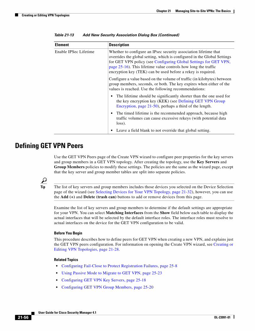
Chapter 21 Managing Site-to-Site VPNs: The BasicsCreating or Editing VPN Topologies
Defining GET VPN PeersUse the GET VPN Peers page of the Create VPN wizard to configure peer properties for the key servers and group members in a GET VPN topology. After creating the topology, use the Key Servers and Group Members policies to modify these settings. The policies are the same as the wizard page, except that the key server and group member tables are split into separate policies.
Tip The list of key servers and group members includes those devices you selected on the Device Selection page of the wizard (see Selecting Devices for Your VPN Topology, page 21-32), however, you can use the Add (+) and Delete (trash can) buttons to add or remove devices from this page.
Examine the list of key servers and group members to determine if the default settings are appropriate for your VPN. You can select Matching Interfaces from the Show field below each table to display the actual interfaces that will be selected by the default interface roles. The interface roles must resolve to actual interfaces on the device for the GET VPN configuration to be valid.
Before You Begin
This procedure describes how to define peers for GET VPN when creating a new VPN, and explains just the GET VPN peers configuration. For information on opening the Create VPN wizard, see Creating or Editing VPN Topologies, page 21-28.
Related Topics
• Configuring Fail-Close to Protect Registration Failures, page 25-8
• Using Passive Mode to Migrate to GET VPN, page 25-23
• Configuring GET VPN Key Servers, page 25-18
• Configuring GET VPN Group Members, page 25-20
Enable IPSec Lifetime Whether to configure an IPsec security association lifetime that overrides the global setting, which is configured in the Global Settings for GET VPN policy (see Configuring Global Settings for GET VPN, page 25-16). This lifetime value controls how long the traffic encryption key (TEK) can be used before a rekey is required.
Configure a value based on the volume of traffic (in kilobytes) between group members, seconds, or both. The key expires when either of the values is reached. Use the following recommendations:
• The lifetime should be significantly shorter than the one used for the key encryption key (KEK) (see Defining GET VPN Group Encryption, page 21-50), perhaps a third of the length.
• The timed lifetime is the recommended approach, because high traffic volumes can cause excessive rekeys (with potential data loss).
• Leave a field blank to not override that global setting.
Table 21-13 Add New Security Association Dialog Box (Continued)
Element Description
21-56User Guide for Cisco Security Manager 4.1
OL-23991-01

Chapter 21 Managing Site-to-Site VPNs: The BasicsCreating or Editing VPN Topologies
Step 1 Configure the key servers if the default settings are not appropriate.
For each key server you want to modify, select it, click the Edit (pencil) button beneath the table, and configure at least following settings. For information on all available settings, see Edit Key Server Dialog Box, page 25-19.
• Identity Interface—Select the interface that group members use to identify the key server and register with it. The default is the Loopback interface role, which identifies all Loopback interfaces defined on the key server.
• Priority—Define the role of the key server as primary or secondary by entering a priority value between 1-100. The key server with the highest priority becomes the primary key server. If two or more key servers are assigned the same priority value, the device with the highest IP address is used. The default priority is 100 for the first key server, 95 for the second, and so on.
Note There can be more than one primary key server if the network is partitioned.
Step 2 Move key servers up or down in the table to specify the order that group members use to register with key servers. Group members register with the first key server in the list. If the first key server cannot be reached, they will register with the second key server, and so on. Note that this order does not define the overall key server priority, which is used to determine which key server is the primary key server.
Step 3 Configure the group members if the default settings are not appropriate.
For each group member you want to modify, select it, click the Edit (pencil) button beneath the table, and configure at least the following settings:
• GET-Enabled Interface—This is the VPN-enabled outside interface to the provider edge (PE). Traffic originating or terminating on this interface is evaluated for encryption or decryption, as appropriate. You can configure multiple interfaces by selecting an interface role object that resolves to more than one interface. Click Select to select an interface role object or to create a new object.
• Interface To Be Used As Local Address—The interface whose IP address is used to identify the group member to the key server for sending data, such as rekey information. If GET is enabled on only one interface, you do not need to specify the interface to be used as the local address. If GET is enabled on more than one interface, you must specify the interface to be used as the local address. Enter the name of the interface or interface role, or click Select to select an interface role.
For information on the other available settings, see Edit Group Member Dialog Box, page 25-21.
Assigning Initial Policies (Defaults) to a New VPN TopologyUse the VPN Defaults page of the Create VPN wizard to view and select the shared site-to-site VPN policies that will be assigned to the VPN topology you are creating. The page displays all the available mandatory and optional policies that can be assigned to your VPN topology, according to the selected IPsec technology. (For more information, see Understanding Mandatory and Optional Policies for Site-to-Site VPNs, page 21-6.)
For information on opening the Create VPN wizard, see Creating or Editing VPN Topologies, page 21-28. After you create the topology, you edit these policies directly.
For each policy type, select the shared VPN policy you want to assign to your VPN topology. Only shared policies are available for selection. Use the following tips to guide your selection:
21-57User Guide for Cisco Security Manager 4.1
OL-23991-01
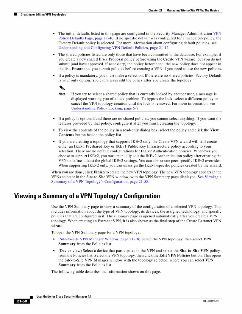
Chapter 21 Managing Site-to-Site VPNs: The BasicsCreating or Editing VPN Topologies
• The initial defaults listed in this page are configured in the Security Manager Administration VPN Policy Defaults Page, page 11-40. If no specific default was configured for a mandatory policy, the Factory Default policy is selected. For more information about configuring default policies, see Understanding and Configuring VPN Default Policies, page 21-12.
• The shared policies listed are only those that have been committed to the database. For example, if you create a new shared IPsec Proposal policy before using the Create VPN wizard, but you do not submit (and have approved, if necessary) the policy beforehand, the new policy does not appear in the list. Ensure that you submit policies before creating a VPN if you need to use the new policies.
• If a policy is mandatory, you must make a selection. If there are no shared policies, Factory Default is your only option. You can always edit the policy after you create the topology.
Note If you try to select a shared policy that is currently locked by another user, a message is displayed warning you of a lock problem. To bypass the lock, select a different policy or cancel the VPN topology creation until the lock is removed. For more information, see Understanding Policy Locking, page 5-7.
• If a policy is optional, and there are no shared policies, you cannot select anything. If you want the features provided by that policy, configure it after you finish creating the topology.
• To view the contents of the policy in a read-only dialog box, select the policy and click the View Contents button beside the policy list.
• If you are creating a topology that supports IKEv2 only, the Create VPN wizard will still create either an IKEv1 Preshared Key or IKEv1 Public Key Infrastructure policy according to your selection. There are no default configurations for IKEv2 Authentication policies. Whenever you choose to support IKEv2, you must manually edit the IKEv2 Authentication policy after creating the VPN to define at least the global IKEv2 settings. You can also create peer-specific IKEv2 overrides. When supporting IKEv2 only, you can unassign the IKEv1-specific policies created by the wizard.
When you are done, click Finish to create the new VPN topology. The new VPN topology appears in the VPNs selector in the Site-to-Site VPN window, with the VPN Summary page displayed. See Viewing a Summary of a VPN Topology’s Configuration, page 21-58.
Viewing a Summary of a VPN Topology’s ConfigurationUse the VPN Summary page to view a summary of the configuration of a selected VPN topology. This includes information about the type of VPN topology, its devices, the assigned technology, and specific policies that are configured in it. The summary page is opened automatically after you create a VPN topology. When creating an Extranet VPN, it is also shown as the final step of the Create Extranet VPN wizard.
To open the VPN Summary page for a VPN topology:
• (Site-to-Site VPN Manager Window, page 21-18) Select the VPN topology, then select VPN Summary from the Policies list.
• (Device view) Select a device that participates in the VPN and select the Site-to-Site VPN policy from the Policies list. Select the VPN topology, then click the Edit VPN Policies button. This opens the Site-to-Site VPN Manager window with the topology selected, where you can select VPN Summary from the Policies list.
The following table describes the information shown on this page.
21-58User Guide for Cisco Security Manager 4.1
OL-23991-01
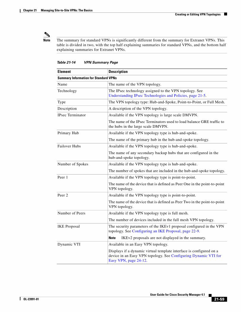
Chapter 21 Managing Site-to-Site VPNs: The BasicsCreating or Editing VPN Topologies
Note The summary for standard VPNs is significantly different from the summary for Extranet VPNs. This table is divided in two, with the top half explaining summaries for standard VPNs, and the bottom half explaining summaries for Extranet VPNs.
Table 21-14 VPN Summary Page
Element Description
Summary Information for Standard VPNs
Name The name of the VPN topology.
Technology The IPsec technology assigned to the VPN topology. See Understanding IPsec Technologies and Policies, page 21-5.
Type The VPN topology type: Hub-and-Spoke, Point-to-Point, or Full Mesh.
Description A description of the VPN topology.
IPsec Terminator Available if the VPN topology is large scale DMVPN.
The name of the IPsec Terminators used to load balance GRE traffic to the hubs in the large scale DMVPN.
Primary Hub Available if the VPN topology type is hub-and-spoke.
The name of the primary hub in the hub-and-spoke topology.
Failover Hubs Available if the VPN topology type is hub-and-spoke.
The name of any secondary backup hubs that are configured in the hub-and-spoke topology.
Number of Spokes Available if the VPN topology type is hub-and-spoke.
The number of spokes that are included in the hub-and-spoke topology.
Peer 1 Available if the VPN topology type is point-to-point.
The name of the device that is defined as Peer One in the point-to-point VPN topology.
Peer 2 Available if the VPN topology type is point-to-point.
The name of the device that is defined as Peer Two in the point-to-point VPN topology.
Number of Peers Available if the VPN topology type is full mesh.
The number of devices included in the full mesh VPN topology.
IKE Proposal The security parameters of the IKEv1 proposal configured in the VPN topology. See Configuring an IKE Proposal, page 22-9.
Note IKEv2 proposals are not displayed in the summary.
Dynamic VTI Available in an Easy VPN topology.
Displays if a dynamic virtual template interface is configured on a device in an Easy VPN topology. See Configuring Dynamic VTI for Easy VPN, page 24-12.
21-59User Guide for Cisco Security Manager 4.1
OL-23991-01

Chapter 21 Managing Site-to-Site VPNs: The BasicsCreating or Editing VPN Topologies
Transform Sets The IPsec IKEv1 transform sets that specify the authentication and encryption algorithms that will be used to secure the traffic in the VPN tunnel. See Configuring IPsec Proposals in Site-to-Site VPNs, page 22-19.
Note IPsec IKEv2 transform sets are not displayed in the summary.
Preshared Key Unavailable if the selected technology is Easy VPN.
Specifies whether the shared key to use in the IKEv1 preshared key policy is user defined or auto-generated. See Configuring IKEv1 Preshared Key Policies, page 22-40.
Note IKEv2 preshared key settings are not displayed in the summary.
Public Key Infrastructure If an IKEv1 Public Key Infrastructure policy is configured in the VPN topology, specifies the certificate authority (CA) server. See Configuring IKEv1 Public Key Infrastructure Policies in Site-to-Site VPNs, page 22-46.
Note IKEv2 PKI configurations are not displayed in the summary.
Routing Protocol Available only if the selected technology is IPsec/GRE, GRE Dynamic IP, or DMVPN.
The routing protocol and autonomous system (or process ID) number used in the secured IGP for configuring a GRE, GRE Dynamic IP, or DMVPN routing policy.
Note Security Manager adds a routing protocol to all the devices in the secured IGP on deployment. If you want to maintain this secured IGP, you must create a router platform policy using this routing protocol and autonomous system (or process ID) number.
See Understanding the GRE Modes Page, page 23-1.
Tunnel Subnet IP Available only if the selected technology is IPsec/GRE, GRE Dynamic IP, or DMVPN.
If a tunnel subnet is defined, displays the inside tunnel interface IP address, including the unique subnet mask.
See Understanding the GRE Modes Page, page 23-1.
User Group Available for an Easy VPN topology.
If a User Group policy is configured on a device in the Easy VPN topology, displays the details of the policy. See Configuring a User Group Policy for Easy VPN, page 24-14.
PIX7.0/ASA Tunnel Group Available for an Easy VPN topology.
If a Connection Profile policy is configured on a PIX Firewall version 7.0+ or ASA appliance in the Easy VPN topology, displays the details of the policy. See Connection Profiles Page, page 27-8.
Table 21-14 VPN Summary Page (Continued)
Element Description
21-60User Guide for Cisco Security Manager 4.1
OL-23991-01
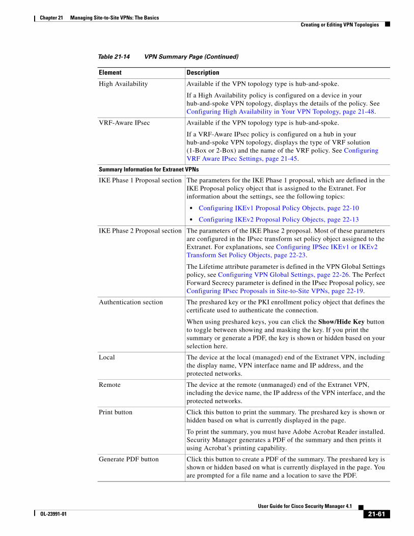
Chapter 21 Managing Site-to-Site VPNs: The BasicsCreating or Editing VPN Topologies
High Availability Available if the VPN topology type is hub-and-spoke.
If a High Availability policy is configured on a device in your hub-and-spoke VPN topology, displays the details of the policy. See Configuring High Availability in Your VPN Topology, page 21-48.
VRF-Aware IPsec Available if the VPN topology type is hub-and-spoke.
If a VRF-Aware IPsec policy is configured on a hub in your hub-and-spoke VPN topology, displays the type of VRF solution (1-Box or 2-Box) and the name of the VRF policy. See Configuring VRF Aware IPsec Settings, page 21-45.
Summary Information for Extranet VPNs
IKE Phase 1 Proposal section The parameters for the IKE Phase 1 proposal, which are defined in the IKE Proposal policy object that is assigned to the Extranet. For information about the settings, see the following topics:
• Configuring IKEv1 Proposal Policy Objects, page 22-10
• Configuring IKEv2 Proposal Policy Objects, page 22-13
IKE Phase 2 Proposal section The parameters of the IKE Phase 2 proposal. Most of these parameters are configured in the IPsec transform set policy object assigned to the Extranet. For explanations, see Configuring IPSec IKEv1 or IKEv2 Transform Set Policy Objects, page 22-23.
The Lifetime attribute parameter is defined in the VPN Global Settings policy, see Configuring VPN Global Settings, page 22-26. The Perfect Forward Secrecy parameter is defined in the IPsec Proposal policy, see Configuring IPsec Proposals in Site-to-Site VPNs, page 22-19.
Authentication section The preshared key or the PKI enrollment policy object that defines the certificate used to authenticate the connection.
When using preshared keys, you can click the Show/Hide Key button to toggle between showing and masking the key. If you print the summary or generate a PDF, the key is shown or hidden based on your selection here.
Local The device at the local (managed) end of the Extranet VPN, including the display name, VPN interface name and IP address, and the protected networks.
Remote The device at the remote (unmanaged) end of the Extranet VPN, including the device name, the IP address of the VPN interface, and the protected networks.
Print button Click this button to print the summary. The preshared key is shown or hidden based on what is currently displayed in the page.
To print the summary, you must have Adobe Acrobat Reader installed. Security Manager generates a PDF of the summary and then prints it using Acrobat’s printing capability.
Generate PDF button Click this button to create a PDF of the summary. The preshared key is shown or hidden based on what is currently displayed in the page. You are prompted for a file name and a location to save the PDF.
Table 21-14 VPN Summary Page (Continued)
Element Description
21-61User Guide for Cisco Security Manager 4.1
OL-23991-01

Chapter 21 Managing Site-to-Site VPNs: The BasicsCreating or Editing Extranet VPNs
Related Topics
• Configuring an IKE Proposal, page 22-9
• Configuring IPsec Proposals in Site-to-Site VPNs, page 22-19
• Configuring IKEv1 Preshared Key Policies, page 22-40
• Configuring IKEv1 Public Key Infrastructure Policies in Site-to-Site VPNs, page 22-46
• Configuring GRE Modes for GRE or GRE Dynamic IP VPNs, page 23-6
• Configuring GRE Modes for DMVPN, page 23-13
• Configuring Large Scale DMVPNs, page 23-17
• Configuring an IPsec Proposal for Easy VPN, page 24-10
• Configuring a User Group Policy for Easy VPN, page 24-14
• Configuring a Connection Profile Policy for Easy VPN, page 24-13
• Creating or Editing Extranet VPNs, page 21-62
Creating or Editing Extranet VPNsSecurity Manager provides a simplified method of creating a regular IPsec point-to-point VPN between a device that you are managing in Security Manager and one that is not managed. This type of VPN is called an Extranet.
Typically, an Extranet is a site-to-site VPN connection between your network and the network of a partner or a service provider. However, it can also be a VPN connection within your organization’s network, but between devices managed by different groups, or between a Cisco device and a non-Cisco device (which Security Manager cannot manage).
Use the Create Extranet VPN wizard to create this type of point-to-point VPN topology. Creating an Extranet VPN involves specifying the devices, the VPN interfaces that are the source and destination endpoints of the VPN tunnel, and the protected networks that will be secured by the tunnel. You also specify the IKE and IPsec proposals and preshared key or certificates required to complete a secure connection.
When you edit an Extranet VPN topology, the Edit Extranet VPN dialog box contains the same pages as the Create Extranet VPN wizard, with the exception of the IKE proposal page, but the pages are laid out in a tabbed format rather than being presented as a wizard. Clicking OK on any tab in the dialog box saves your definitions on all the tabs. For IKE proposals, IPsec proposals, preshared keys, and Public Key Infrastructure certificates, you must edit the policies directly.
Tips
• VPN default policies do not apply to Extranet VPNs. The settings defined on the Security Manager Administration VPN Defaults page are ignored. If you have shared policies that you want to use in the Extranet VPN configuration, you can assign them to the VPN after you create it with the Create Extranet VPN wizard. Assigning the shared policy replaces the policy created by the wizard.
• You cannot select your pre-defined IKE proposal or IPsec transform set policy objects when creating an Extranet VPN. If you have existing objects that you want to use, you can edit the relevant policies after creating the VPN and select the objects. You can then delete the objects created by the Create Extranet VPN wizard, if desired.
• After creating an Extranet VPN, you cannot convert it to a standard point-to-point VPN, where you are managing both ends of the VPN in Security Manager. Instead, you must delete and recreate the VPN.
21-62User Guide for Cisco Security Manager 4.1
OL-23991-01
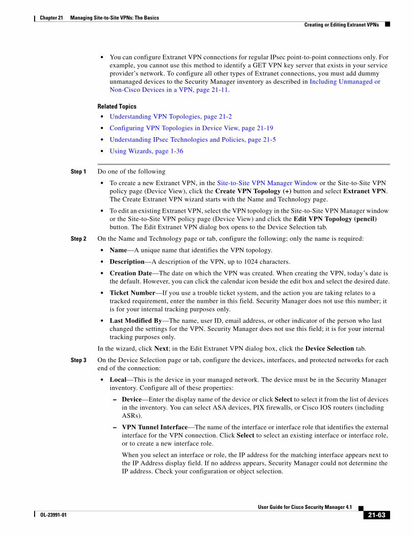
Chapter 21 Managing Site-to-Site VPNs: The BasicsCreating or Editing Extranet VPNs
• You can configure Extranet VPN connections for regular IPsec point-to-point connections only. For example, you cannot use this method to identify a GET VPN key server that exists in your service provider’s network. To configure all other types of Extranet connections, you must add dummy unmanaged devices to the Security Manager inventory as described in Including Unmanaged or Non-Cisco Devices in a VPN, page 21-11.
Related Topics
• Understanding VPN Topologies, page 21-2
• Configuring VPN Topologies in Device View, page 21-19
• Understanding IPsec Technologies and Policies, page 21-5
• Using Wizards, page 1-36
Step 1 Do one of the following
• To create a new Extranet VPN, in the Site-to-Site VPN Manager Window or the Site-to-Site VPN policy page (Device View), click the Create VPN Topology (+) button and select Extranet VPN. The Create Extranet VPN wizard starts with the Name and Technology page.
• To edit an existing Extranet VPN, select the VPN topology in the Site-to-Site VPN Manager window or the Site-to-Site VPN policy page (Device View) and click the Edit VPN Topology (pencil) button. The Edit Extranet VPN dialog box opens to the Device Selection tab.
Step 2 On the Name and Technology page or tab, configure the following; only the name is required:
• Name—A unique name that identifies the VPN topology.
• Description—A description of the VPN, up to 1024 characters.
• Creation Date—The date on which the VPN was created. When creating the VPN, today’s date is the default. However, you can click the calendar icon beside the edit box and select the desired date.
• Ticket Number—If you use a trouble ticket system, and the action you are taking relates to a tracked requirement, enter the number in this field. Security Manager does not use this number; it is for your internal tracking purposes only.
• Last Modified By—The name, user ID, email address, or other indicator of the person who last changed the settings for the VPN. Security Manager does not use this field; it is for your internal tracking purposes only.
In the wizard, click Next; in the Edit Extranet VPN dialog box, click the Device Selection tab.
Step 3 On the Device Selection page or tab, configure the devices, interfaces, and protected networks for each end of the connection:
• Local—This is the device in your managed network. The device must be in the Security Manager inventory. Configure all of these properties:
– Device—Enter the display name of the device or click Select to select it from the list of devices in the inventory. You can select ASA devices, PIX firewalls, or Cisco IOS routers (including ASRs).
– VPN Tunnel Interface—The name of the interface or interface role that identifies the external interface for the VPN connection. Click Select to select an existing interface or interface role, or to create a new interface role.
When you select an interface or role, the IP address for the matching interface appears next to the IP Address display field. If no address appears, Security Manager could not determine the IP address. Check your configuration or object selection.
21-63User Guide for Cisco Security Manager 4.1
OL-23991-01

Chapter 21 Managing Site-to-Site VPNs: The BasicsCreating or Editing Extranet VPNs
– Protected Networks—The networks that the device is protecting for this VPN. Enter either the name of a network/host policy object, or enter the network addresses directly (such as 10.100.10.0/24). Separate multiple entries with commas. The content of the selected objects is evaluated and displayed beneath the edit box so that you can verify that you selected the desired objects.
Note If you want to specify the protected networks using an interface name, interface role object, or ACL object, you must edit the Peers policy as described in Defining the Endpoints and Protected Networks, page 21-33. When creating the Extranet VPN, use a dummy network, then be sure to edit the Peers policy immediately after finishing the wizard.
• Remote—This is the device that you are not managing in Security Manager. Configure all of these properties:
– Name—The name of the device, equivalent to the display name used in the Security Manager inventory.
– IP Address—The IP address of the VPN interface on the device.
– Protected Networks—The networks that the device is protecting for this VPN. Enter either the name of a network/host policy object, or enter the network addresses directly (such as 10.100.10.0/24). Separate multiple entries with commas. The content of the selected objects is evaluated and displayed beneath the edit box so that you can verify that you selected the desired objects.
Note You can also edit the remote device endpoint settings as described in Defining the Endpoints and Protected Networks, page 21-33. However, the settings are identical to these, and you cannot specify the protected networks using an interface name, interface role object, or ACL object.
In the wizard, click Next. In the Edit VPN dialog box, you are finished; to edit the remaining characteristics, you must edit the IKE Proposal, IPsec Proposal, IKEv1 Preshared Key, IKEv1 Public Key Infrastructure, IKEv2 Authentication, and VPN Global Settings policies to change the settings described in the next step.
Step 4 On the IKE Proposal page of the Create Extranet VPN wizard, define the IKE proposal, the IPsec proposal, and either the preshared key or the certificate:
• Select IKEv1 or IKEv2. You can use IKEv2 on ASA devices running release 8.4(1)+ only.
If you want to change IKE versions after creating the Extranet VPN, you must edit all of these policies to unassign or replace the old configuration while configuring options for the desired version: IKE Proposal, IPsec Proposal, IKEv1 Preshared Key, IKEv1 Public Key Infrastructure, IKEv2 Authentication, VPN Global Settings.
• Configure the IKE Phase 1 Proposal parameters. These parameters will be used to create an IKE proposal policy object with the name ExtranetName_ikeBB. For an explanation of the parameters, see Configuring IKEv1 Proposal Policy Objects, page 22-10.
To edit these values after creating the VPN, you simply need to edit the object. You can edit the object in the Policy Object Manager or directly through the IKE Proposal policy for the VPN.
21-64User Guide for Cisco Security Manager 4.1
OL-23991-01

Chapter 21 Managing Site-to-Site VPNs: The BasicsCreating or Editing Extranet VPNs
Note The DH Group attribute (for Diffie-Hellman modulus group) is called Modulus Group in other policies and policy objects.
• Configure the IKE Phase 2 (IPsec) Proposal parameters. Most of these parameters will be used to create an IPsec transform set policy object with the name ExtranetName_transformSet. For an explanation of the parameters, see Configuring IPSec IKEv1 or IKEv2 Transform Set Policy Objects, page 22-23. Note that the AH Hash Algorithm setting is available only if the local device is a router.
To edit these values after creating the VPN, you simply need to edit the object. You can edit the object in the Policy Object Manager or directly through the IPsec Proposal policy for the VPN.
The following settings are not part of the IPsec transform set object:
– Enable Perfect Forward Secrecy, DH Group—Whether to use a unique session key for each encrypted exchange, which prevents an attacker from decrypting a captured exchange even if the attacker knows the preshared or private keys used by both ends of the tunnel. If you select this option, also select the Diffie-Hellman (DH) modulus group to use for deriving the key. For more information on the modulus group, see Deciding Which Diffie-Hellman Modulus Group to Use, page 22-7.
To change this option after creating the VPN, edit the IPsec Proposal policy.
– Lifetime—The number of seconds a security association will exist before expiring. The default is 3,600 seconds (one hour).
To change this option after creating the VPN, edit the VPN Global Settings policy.
• If you select Preshared Key for authentication, enter the key used to authenticate connections with the remote host.
To edit the key after creating the VPN, you must edit either the IKEv1 Preshared Key or IKEv2 Authentication policy depending on the IKE version you are using. The key is masked in these policies, but you can display the key by selecting the VPN Summary policy and clicking the Show Key button beside the preshared key.
• If you select Certificate, select the PKI enrollment object that defines the certificate name. If the required object is not yet defined, select <Add New> to open the Add PKI selector, from which you can add new, or edit existing, PKI enrollment objects. For more information about PKI enrollment objects, see PKI Enrollment Dialog Box, page 22-50.
To edit the certificate settings after creating the VPN, you can edit the object in the Policy Object Manager or directly through either the IKEv1 Public Key Infrastructure or IKEv2 Authentication policy depending on the IKE version you are using.
In the wizard, click Next.
Step 5 (Create Extranet VPN wizard only.) On the Summary page, verify that the settings are correct and click Finish.
Security Manager creates the topology and the required policy objects, and adds the VPN to the list of VPNs in the Site-to-Site VPN Manager.
Step 6 If you want to configure dial backup, select the Peers policy and follow the instructions in Configuring Dial Backup, page 21-38.
21-65User Guide for Cisco Security Manager 4.1
OL-23991-01

Chapter 21 Managing Site-to-Site VPNs: The BasicsDeleting a VPN Topology
Deleting a VPN TopologyDeleting a VPN topology removes IPsec tunnels between peers and all configurations associated with the VPN topology from the devices and networks assigned to the site-to-site VPN. The actual VPN is not removed from the network until you deploy configurations.
Step 1 Do one of the following:
• Select Manage > Site-To-Site VPNs to open the Site-to-Site VPN Manager Window, page 21-18.
• In Device view, select a device that participates in the VPN you want to delete, then select the Site to Site VPN policy from the policy selector (see Configuring VPN Topologies in Device View, page 21-19).
Step 2 Select the VPN topology you want to delete and click the Delete VPN Topology (trash can) button. You are asked to confirm the deletion.
21-66User Guide for Cisco Security Manager 4.1
OL-23991-01