mana dawuch small scale irrigation project … ssip...manna_dawch small scale intake irrigation...
TRANSCRIPT

Manna_Dawch Small Scale Intake Irrigation Project Engineering Design Final Report
ADSWE, Irrigation & Drainage P.O. Box: 1921 Tel: 058--218--06--38/10 23 Fax : 058--218-0550/0560 Page ii
Manna_Dawch Small Scale Intake Irrigation Project Engineering Design Final Report
ADSWE, Irrigation & Drainage P.O. Box: 1921 Tel: 058--218--06--38/10 23 Fax : 058--218-0550/0560 Page iii
Amhara National Regional State
Water, Irrigation & Energy Development Bureau
(BOWIED)
Detail Design
of
Menna_Dawch Small-Scale Intake Irrigation Project
Volume IV: Engineering Design Final Report
March, 2016(Revised 2016)
Bahir Dar
Client: Bureau of Water, Irrigation & Energy Development
(BoWIED)
Address:
P. O. Box: 88
Telephone: 0528-200853/855
Fax: 251-08-20-65-68/204676/202040
Consultant: Amhara Design & Supervision Works Enterprise
(ADSWE)
Address:
P. O. Box: 1921
Telephone: +251-582-181023/ 180638/181201/181254
Fax: (058) 2180550/ (058) 2180560
E-mail: amhara [email protected]
Bahir Dar, Ethiopia

Manna_Dawch Small Scale Intake Irrigation Project Engineering Design Final Report
ADSWE, Irrigation & Drainage P.O. Box: 1921 Tel: 058--218--06--38/10 23 Fax : 058--218-0550/0560 Page i
List of Reports
Volume I: Watershed Management
Volume II: Engineering Geology
Volume III: Irrigation Agronomy
Volume IV: Engineering Design
Volume V: Socio Economy
Volume VI: Environmental Impact Assessment
Volume VII: Economic and Financial Analysis
Manna_Dawch Small Scale Intake Irrigation Project Engineering Design Final Report
ADSWE, Irrigation & Drainage P.O. Box: 1921 Tel: 058--218--06--38/10 23 Fax : 058--218-0550/0560 Page ii
Table of Contents Page Nr
List of Reports.................................................................................................................................. i
LIST OF TABLES .......................................................................................................................... v
LIST OF FIGURES ........................................................................................................................ v
SAILENT FEATURE .................................................................................................................... vi
1 INTRODUCTION ................................................................................................................... 1
1.1 Background ...................................................................................................................... 1
1.1.1 Description of the Project Area................................................................................. 1
1.2 Objectives of the Study .................................................................................................... 2
1.2.1 Major Objective ........................................................................................................ 2
1.2.2 Specific Objectives ................................................................................................... 3
1.3 Scope of the Study............................................................................................................ 4
1.4 Methodology .................................................................................................................... 4
2 HYDROLOGY ........................................................................................................................ 6
2.1 Watershed Characteristics ................................................................................................ 6
2.2 Hydro-Metrological Data Availability ............................................................................. 7
2.2.1 Climate ...................................................................................................................... 7
2.2.2 Rainfall Data ............................................................................................................. 8
2.2.3 River flow data .......................................................................................................... 8
2.2.4 Upstream & Downstream utilization ........................................................................ 8
2.3 Design Flood Analysis ..................................................................................................... 8
2.3.1 Design Rainfall computation .................................................................................... 9
2.3.2 Peak Discharge Determination ............................................................................... 11
2.3.3 Tail Water Depth Computation ............................................................................... 15
3 HEADWORK DESIGN ........................................................................................................ 19
3.1 Headwork Site Selection ................................................................................................ 19
Manna_Dawch Small Scale Intake Irrigation Project Engineering Design Final Report
ADSWE, Irrigation & Drainage P.O. Box: 1921 Tel: 058--218--06--38/10 23 Fax : 058--218-0550/0560 Page iii
3.2 River Geology ................................................................................................................ 19
3.2.1 River Bed condition ................................................................................................ 20
3.2.2 River Bank Condition ............................................................................................. 21
3.3 Headwork Type Selection .............................................................................................. 22
3.4 Hydraulic Design of Headwork Structure ...................................................................... 22
3.4.1 Intake Height or Scour Depth Determination ......................................................... 22
3.4.2 Intake Dimensions .................................................................................................. 23
3.4.3 Outlet Design .......................................................................................................... 23
3.4.4 Retaining Wall Analysis ......................................................................................... 24
4 IRRIGATION AND DRAINAGE SYSTEMS DESIGN ...................................................... 25
4.1 Irrigable Area Description .............................................................................................. 25
4.1.1 Topography ............................................................................................................. 25
4.1.2 Soil characteristics .................................................................................................. 25
4.2 Irrigation Water Requirement ........................................................................................ 25
4.2.1 Crop Water Requirement (CWR) ........................................................................... 25
4.2.2 Irrigation efficiency (Ep) ........................................................................................ 26
4.2.3 Irrigation duty ......................................................................................................... 26
4.2.4 Irrigation Methods .................................................................................................. 27
4.3 Irrigation and Drainage System Layout ......................................................................... 28
4.3.1 Main Canal .............................................................................................................. 29
4.3.2 Secondary Canals .................................................................................................... 35
4.3.3 Tertiary canals ......................................................................................................... 36
4.3.4 Design of Division box ........................................................................................... 38
4.3.5 Road Crossing Structure ......................................................................................... 41
4.3.6 Drop structure ......................................................................................................... 41
Manna_Dawch Small Scale Intake Irrigation Project Engineering Design Final Report
ADSWE, Irrigation & Drainage P.O. Box: 1921 Tel: 058--218--06--38/10 23 Fax : 058--218-0550/0560 Page iv
4.3.7 Design of a Typical Flume ...................................................................................... 43
4.3.8 Drainage System.................................................................................................... 44
5 SOURCES OF CONSTRUCTION MATERIALS ............................................................... 45
5.1 Rock for Masonry and Crushed Coarse Aggregate ........................................................ 45
5.2 Fine Aggregates.............................................................................................................. 45
5.3 Water .............................................................................................................................. 46
6 OPERATION AND MAINTENANCE................................................................................. 47
6.1 General ........................................................................................................................... 47
6.2 Operation of the Head Works......................................................................................... 47
6.3 Irrigation System Operation ........................................................................................... 47
6.4 Maintenance Requirement.............................................................................................. 47
7 CONCLUSION AND RECOMMENDATION .................................................................... 49
8 REFERENCE ........................................................................................................................ 50
Manna_Dawch Small Scale Intake Irrigation Project Engineering Design Final Report
ADSWE, Irrigation & Drainage P.O. Box: 1921 Tel: 058--218--06--38/10 23 Fax : 058--218-0550/0560 Page v
LIST OF TABLES
TABLE 2-1: THE SLOPE CLASSES AND PROPORTION OF THE WATER SHED ..................................................................... 6
TABLE 2-2: OUTLIER TEST ANALYSIS ............................................................................................................................ 9
TABLE 2-3: TEST FOR GOODNESS TO FIT USING D-INDEX ............................................................................................ 10
TABLE 2-4: RUNOFF ANALYSIS ..................................................................................................................................... 13
TABLE 2-5: HYDROGRAPH COORDINATES .................................................................................................................... 14
TABLE 2-6: STAGE DISCHARGE ANALYSIS ................................................................................................................... 15
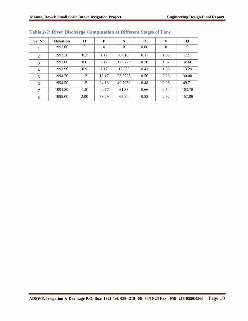
TABLE 2-7: RIVER DISCHARGE COMPUTATION AT DIFFERENT STAGES OF FLOW ........................................................ 18
TABLE 3-1: TYPICAL DESIGN OF MASONRY RETAINING WALL ...................................................................................... 24
TABLE 4-1: HYDRAULIC PARAMETERS OF MAIN CANAL .............................................................................................. 34
TABLE 4-2: HYDRAULIC PARAMETERS OF SECONDARY CANALS .................................................................................. 35
TABLE 4-3: HYDRAULIC PARAMETERS OF TERTIARY CANALS ..................................................................................... 36
TABLE 4-4: HYDRAULIC PARAMETERS OF DIVISION BOXES ......................................................................................... 40
TABLE 4-5: DROP HYDRAULIC DESIGN ........................................................................................................................ 43
TABLE 4-6: HYDRAULIC PARAMETERS OF FLUME ........................................................................................................ 44
LIST OF FIGURES
FIGURE 1-1: LOCATION MAP OF THE PROJECT AREA...................................................................................................... 2
FIGURE 2-1: DRAINAGE MAP OF MENNA_DAWCH WATERSHED .................................................................................... 7
FIGURE 2-2: COMPLEX HYDROGRAPH .......................................................................................................................... 14
FIGURE 2-3: HEADWORK SITE RIVER SECTION............................................................................................................. 15
FIGURE 2-4: RATING CURVE ........................................................................................................................................ 16
FIGURE 2-6: RIVER SLOPE PROFILE .............................................................................................................................. 17
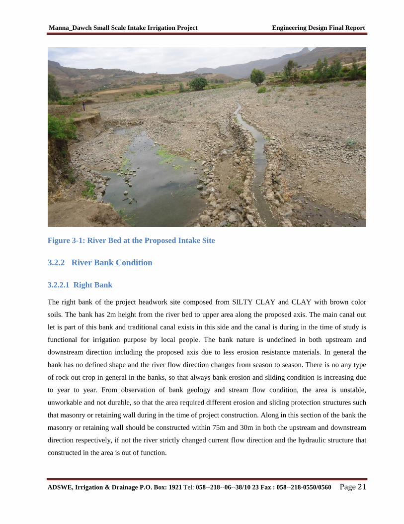
FIGURE 3-1: RIVER BED AT THE PROPOSED INTAKE SITE ............................................................................................. 21
FIGURE 4-1: TYPICAL CROSS SECTION OF TERTIARY CANALS ...................................................................................... 36
FIGURE 4-2: TYPICAL DIVISION BOX PLAN ................................................................................................................... 38
Manna_Dawch Small Scale Intake Irrigation Project Engineering Design Final Report
ADSWE, Irrigation & Drainage P.O. Box: 1921 Tel: 058--218--06--38/10 23 Fax : 058--218-0550/0560 Page vi
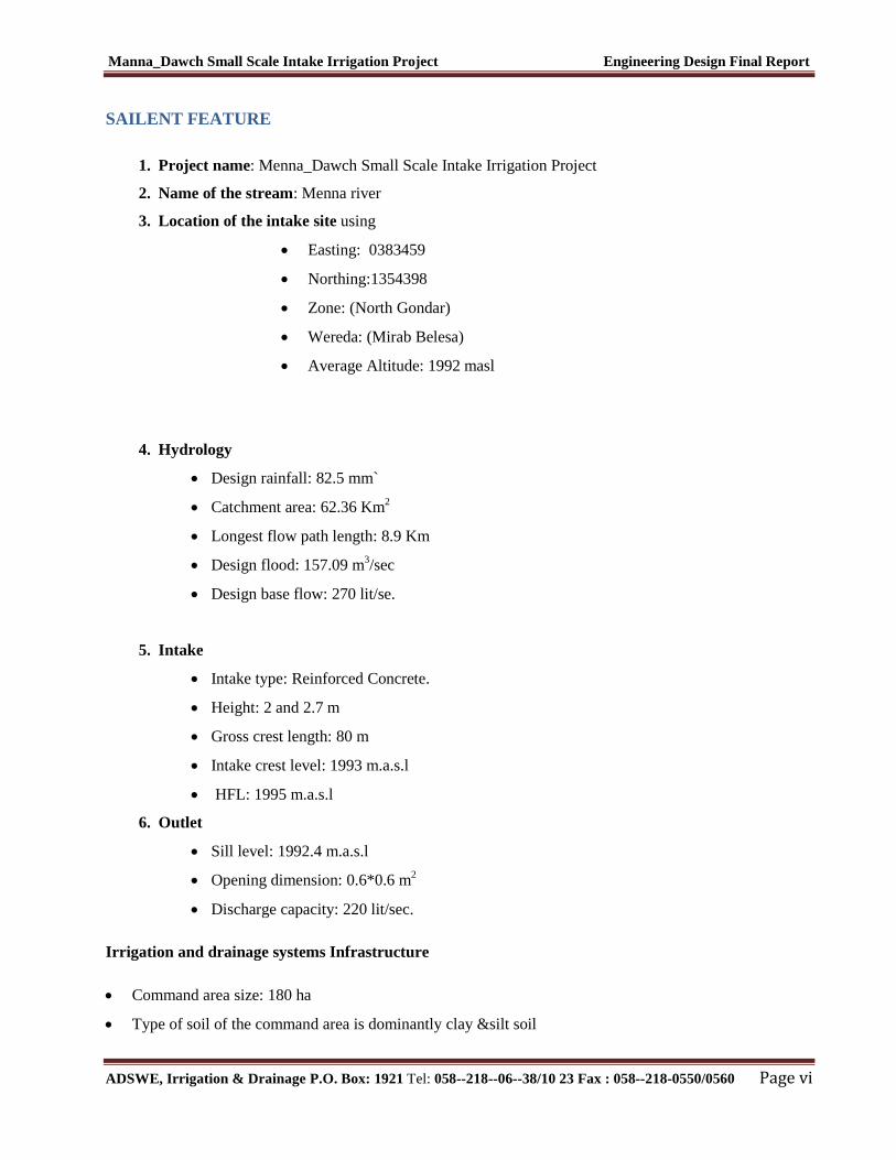
SAILENT FEATURE
1. Project name: Menna_Dawch Small Scale Intake Irrigation Project
2. Name of the stream: Menna river
3. Location of the intake site using
Easting: 0383459
Northing:1354398
Zone: (North Gondar)
Wereda: (Mirab Belesa)
Average Altitude: 1992 masl
4. Hydrology
Design rainfall: 82.5 mm`
Catchment area: 62.36 Km2
Longest flow path length: 8.9 Km
Design flood: 157.09 m3/sec
Design base flow: 270 lit/se.
5. Intake
Intake type: Reinforced Concrete.
Height: 2 and 2.7 m
Gross crest length: 80 m
Intake crest level: 1993 m.a.s.l
HFL: 1995 m.a.s.l
6. Outlet
Sill level: 1992.4 m.a.s.l
Opening dimension: 0.6*0.6 m2
Discharge capacity: 220 lit/sec.
Irrigation and drainage systems Infrastructure
Command area size: 180 ha
Type of soil of the command area is dominantly clay &silt soil
Manna_Dawch Small Scale Intake Irrigation Project Engineering Design Final Report
ADSWE, Irrigation & Drainage P.O. Box: 1921 Tel: 058--218--06--38/10 23 Fax : 058--218-0550/0560 Page vii
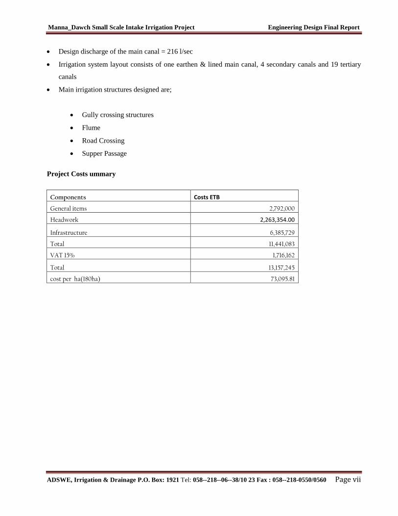
Design discharge of the main canal = 216 l/sec
Irrigation system layout consists of one earthen & lined main canal, 4 secondary canals and 19 tertiary
canals
Main irrigation structures designed are;
Gully crossing structures
Flume
Road Crossing
Supper Passage
Project Costs ummary
Components Costs ETB
General items 2,792,000
Headwork 2,263,354.00
Infrastructure 6,385,729
Total 11,441,083
VAT 15% 1,716,162
Total 13,157,245
cost per ha(180ha) 73,095.81
Manna_Dawch Small Scale Intake Irrigation Project Engineering Design Final Report
ADSWE, Irrigation & Drainage P.O. Box: 1921 Tel: 058--218--06--38/10 23 Fax : 058--218-0550/0560 Page 1
1 INTRODUCTION
1.1 Background
In Ethiopia, under the prevalent rain-fed agricultural production system, the progressive degradation of the
natural resource base, especially in highly vulnerable areas of the highlands coupled with climate variability
have aggravated the incidence of poverty and food insecurity. The major source of growth for Ethiopia is still
conceived to be the agriculture sector. Hence, this sector has to be insulated from drought shocks through
enhanced utilization of the water resource potential of the country, (through development of small-scale
irrigation, water harvesting, and on-farm diversification) coupled with strengthened linkages between
agriculture and industry (agro-industry), thereby creating a demand for agricultural output. In line with the
above, efforts have been made by the government to improve the situation in the country in areas of domestic
water supply provision, irrigation, watershed Management, etc. The Amhara Water Resources Development
Bureau is playing its role in the development of small scale irrigation projects in the region. Accordingly, as
part of the water sector development program, the office has initiated the study and design of a small scale
irrigation scheme on Menna River at Dawch Kebele and signed an agreement with Amhara Design &
Supervision Works Enterprise (ADSWE) for the study and design of the project.
1.1.1 Description of the Project Area
1.1.1.1 Location
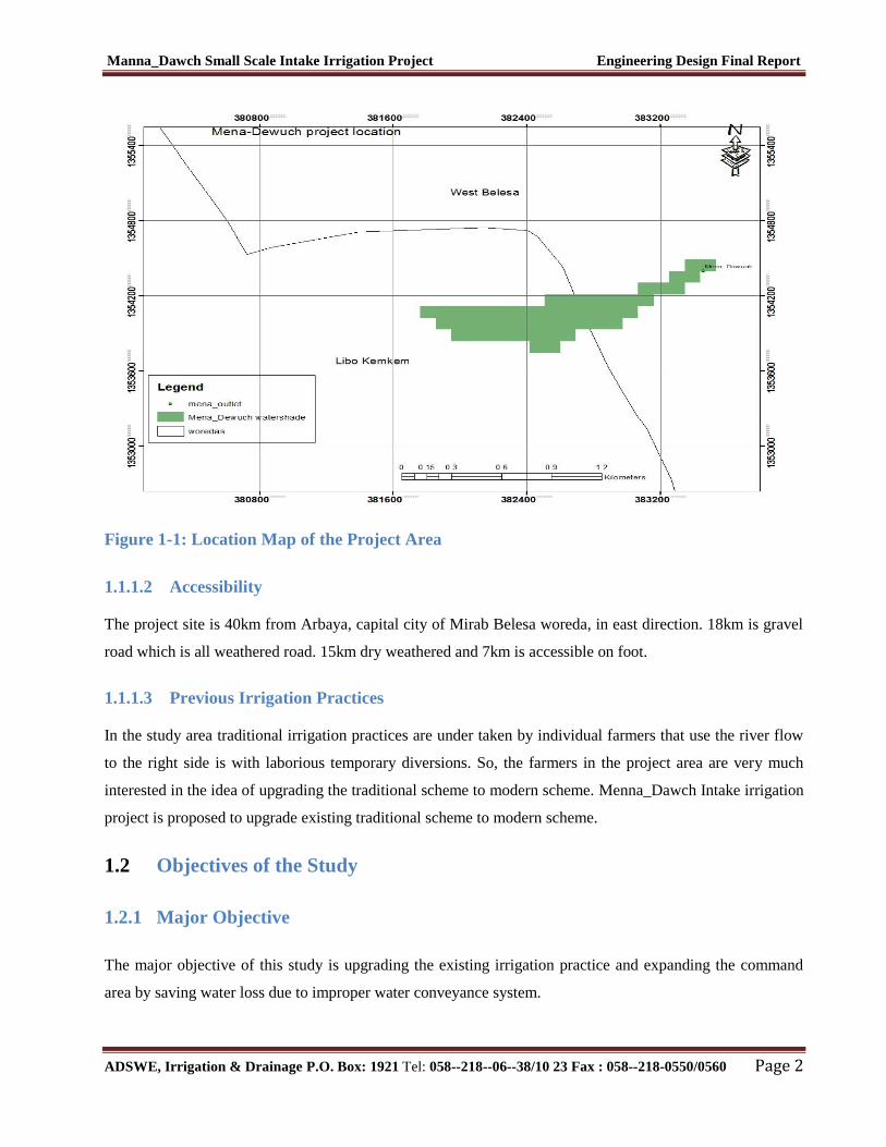
Menna_Dawch irrigation project is located mainly at Dawch Keble, Mirab Belesa Wereda of North Gondar
Zone in the Amhara Region. The proposed irrigation project is to be undertaken on Menna River and the
headwork structures are specifically located at an altitude of about 1992 masl and geographical coordinates
of 1354398 N and 0383459 E (UTM, ADINDAN).
Manna_Dawch Small Scale Intake Irrigation Project Engineering Design Final Report
ADSWE, Irrigation & Drainage P.O. Box: 1921 Tel: 058--218--06--38/10 23 Fax : 058--218-0550/0560 Page 2
Figure 1-1: Location Map of the Project Area
1.1.1.2 Accessibility
The project site is 40km from Arbaya, capital city of Mirab Belesa woreda, in east direction. 18km is gravel
road which is all weathered road. 15km dry weathered and 7km is accessible on foot.
1.1.1.3 Previous Irrigation Practices
In the study area traditional irrigation practices are under taken by individual farmers that use the river flow
to the right side is with laborious temporary diversions. So, the farmers in the project area are very much
interested in the idea of upgrading the traditional scheme to modern scheme. Menna_Dawch Intake irrigation
project is proposed to upgrade existing traditional scheme to modern scheme.
1.2 Objectives of the Study
1.2.1 Major Objective
The major objective of this study is upgrading the existing irrigation practice and expanding the command
area by saving water loss due to improper water conveyance system.
Manna_Dawch Small Scale Intake Irrigation Project Engineering Design Final Report
ADSWE, Irrigation & Drainage P.O. Box: 1921 Tel: 058--218--06--38/10 23 Fax : 058--218-0550/0560 Page 3
Hence the objective of this project is to contribute a substantial share in the effort to reduce the risk of
production decrease due to rainfall variability, reducing water loss and increase the productivity of the
resource in the project specific area. Specifically, the project is targeted for the following.
To make sustainable the rain-fed crop production and make extra production in the dry season
possible for 180 ha of land through irrigation.
There is a general consensus that irrigation investments will achieve broader food security and
poverty reduction impacts and if efforts are also geared towards up-grading existing traditional
farming practices with support to enhance access to input supply, output marketing and extension to
facilitate access to information and innovations.
This objective is to be realized by constructing intake structures across the Menna River and
diverting the river flow.
1.2.2 Specific Objectives
Other benefits that can be expected to appear with the launching of the project are:
Efficiency of water use improvement;
Improved local nutrition/food security gains;
Improved Management of scarce natural resources (land and water);
Resilience against drought risk;
Rationale for erosion control and watershed Management;
Rationale for the intensification and modernization of small-holder agriculture and rural lifestyles.
The engineering study and design enables the realization of the project by the provision of
engineering structures that will allow the appropriate abstraction of the river water for delivery in to
the identified irrigation fields of the study area. Hence, this engineering design is specifically
targeted to:
Analyze hydrologic requirements of the project and engineering structures;
The formulation of sound and stable structure, with necessary provisions that allow safe, easy and
low-maintenance operation in the service life of the project;
Design canals, flumes, super passages, division boxes and foot path roads
Develop working drawings;
Estimation of construction costs.
Manna_Dawch Small Scale Intake Irrigation Project Engineering Design Final Report
ADSWE, Irrigation & Drainage P.O. Box: 1921 Tel: 058--218--06--38/10 23 Fax : 058--218-0550/0560 Page 4
1.3 Scope of the Study
The irrigation design shall ensure reliability, equity and flexibility of water delivery to farmers. It will
aim at reducing conflicts among water users and will lead to lower operation and maintenance costs.
Updating the existing computation of the actual evapo-transpiration, crop water requirement, irrigation
demand/duty using the existing and recent agronomic, climatologic and soil data using more appropriate
methodologies.
Design proper irrigation system compatible with local conditions and Management capabilities,
Planning and layout of the irrigation system, which include irrigation canals, drainage channels,
inspection roads and alignments, canal spacing, canal length, location of structures, and water profiles
along canal and drains at specified reaches, which is most economical easily Manageable and aligned
with topographic feature and geological investigation.
Determination and estimation of water application conveyance and other losses and irrigation
efficiencies and consideration of those parameters in design steps.
Check and test hydraulic and structural designs of main canal considering total demand and the required
capacity and the base flow availability,
Prepare general plans and drawings for all irrigation infrastructure and irrigation systems designs,
1.4 Methodology
In the study and design procedure, Designers used the following steps.
Specific Site identification:
o DEM, Google earth
o Local farmers interview and discussion
o Wereda and Zone Agriculture section expertise
o On foot travel along the river channel and farm areas.
Topographic survey:
o Surveying the headwork site and the Command area with sufficient radius, using Total station
Flow estimation
o Physical observation on flood mark indications and local information about high flood and
critical flow condition of the river
o Base flow estimated during the reconnaissance field visit by floating method.
Irrigable area identification:
o Using local information

Manna_Dawch Small Scale Intake Irrigation Project Engineering Design Final Report
ADSWE, Irrigation & Drainage P.O. Box: 1921 Tel: 058--218--06--38/10 23 Fax : 058--218-0550/0560 Page 5
o Detail Topographic Surveying data map.
Study and design of the irrigation method to be adopted,
Study and design of the irrigation system layout and associated structures,
Design of the different conveyance canals,
Planning and design of the different irrigation and drainage structures,
Preparation of the longitudinal profiles of the different irrigation and drainage canals.
Manna_Dawch Small Scale Intake Irrigation Project Engineering Design Final Report
ADSWE, Irrigation & Drainage P.O. Box: 1921 Tel: 058--218--06--38/10 23 Fax : 058--218-0550/0560 Page 6
2 HYDROLOGY
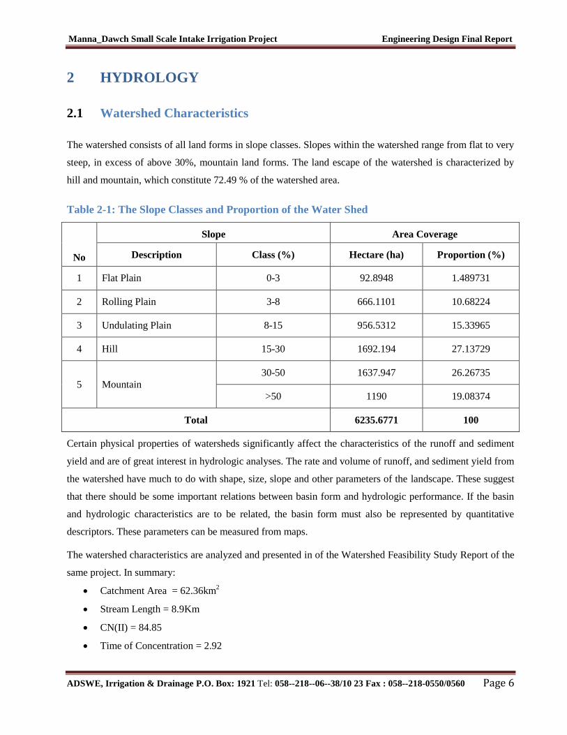
2.1 Watershed Characteristics
The watershed consists of all land forms in slope classes. Slopes within the watershed range from flat to very
steep, in excess of above 30%, mountain land forms. The land escape of the watershed is characterized by
hill and mountain, which constitute 72.49 % of the watershed area.
Table 2-1: The Slope Classes and Proportion of the Water Shed
No
Slope
Slope Class (%)
Area Coverage
Description Class (%) Hectare (ha) Proportion (%)
1 Flat Plain 0-3 92.8948 1.489731
2 Rolling Plain 3-8 666.1101 10.68224
3 Undulating Plain 8-15 956.5312 15.33965
4 Hill 15-30 1692.194 27.13729
5 Mountain
30-50 1637.947 26.26735
>50 1190 19.08374
Total 6235.6771 100
Certain physical properties of watersheds significantly affect the characteristics of the runoff and sediment
yield and are of great interest in hydrologic analyses. The rate and volume of runoff, and sediment yield from
the watershed have much to do with shape, size, slope and other parameters of the landscape. These suggest
that there should be some important relations between basin form and hydrologic performance. If the basin
and hydrologic characteristics are to be related, the basin form must also be represented by quantitative
descriptors. These parameters can be measured from maps.
The watershed characteristics are analyzed and presented in of the Watershed Feasibility Study Report of the
same project. In summary:
Catchment Area = 62.36km2
Stream Length = 8.9Km
CN(II) = 84.85
Time of Concentration = 2.92
Manna_Dawch Small Scale Intake Irrigation Project Engineering Design Final Report
ADSWE, Irrigation & Drainage P.O. Box: 1921 Tel: 058--218--06--38/10 23 Fax : 058--218-0550/0560 Page 7
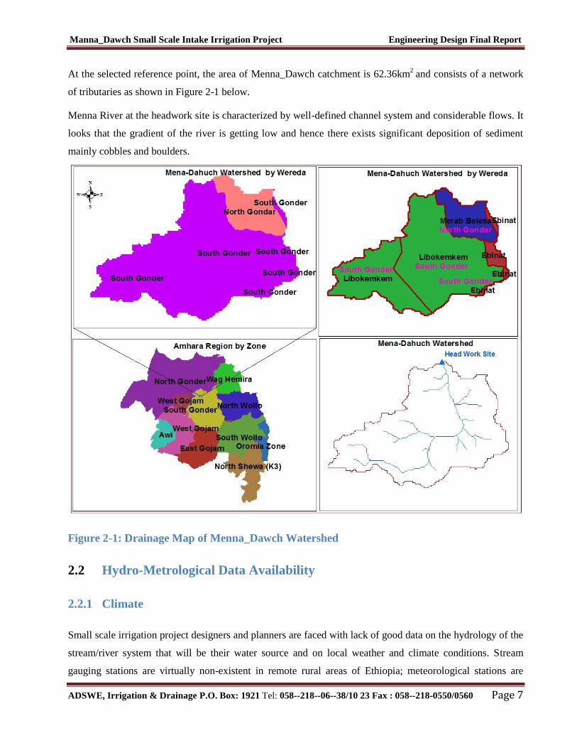
At the selected reference point, the area of Menna_Dawch catchment is 62.36km2
and consists of a network
of tributaries as shown in Figure 2-1 below.
Menna River at the headwork site is characterized by well-defined channel system and considerable flows. It
looks that the gradient of the river is getting low and hence there exists significant deposition of sediment
mainly cobbles and boulders.
Figure 2-1: Drainage Map of Menna_Dawch Watershed
2.2 Hydro-Metrological Data Availability
2.2.1 Climate
Small scale irrigation project designers and planners are faced with lack of good data on the hydrology of the
stream/river system that will be their water source and on local weather and climate conditions. Stream
gauging stations are virtually non-existent in remote rural areas of Ethiopia; meteorological stations are
Manna_Dawch Small Scale Intake Irrigation Project Engineering Design Final Report
ADSWE, Irrigation & Drainage P.O. Box: 1921 Tel: 058--218--06--38/10 23 Fax : 058--218-0550/0560 Page 8
almost rare. Likewise, at Dawch Kebele (Project area location) and in the catchment area of this project,
there is no meteorological station of any level. Moreover, there are no flow data for the river near the project.
Therefore, data for the hydro-meteorological analysis is taken from the nearby station and similar areas.
Rainfall & temperature data are considered from Addis Zemen Meteorological station. In fact, this station is
very close to the project area about 10km.
As per the data of the station, March – April are identified as high temperature periods whereas December–
January are low temperature periods. The mean annual rainfall amount is more than 44.42mm (1998 - 2008
data) and most of it occurs from June to August.
2.2.2 Rainfall Data
In order to compute the design flood for the Intake structure, the daily maximum rainfall is collected from
Addis Zemen Metrological stations with a record of 12 years.
2.2.3 River flow data
The base flow which is measured on April 2007 E.C is 270 l/s. Since this base flow is measured during the
dry months of the year, this figure is adopted for design.
2.2.4 Upstream & Downstream utilization
Downstream of the proposed site, appreciable need for water is anticipated for locals and cattle provisions.
Therefore, at least 54 l/s (21%)of the minimum flow has to be released for downstream requirements and the
river has ground water at downstream so that there is no any conflict between u/s and d/s of the projects.
For the sake of planning and design, however, the outlet for the intake is designed for a discharge of 220l/s
for this project and the project is to be developed for 180 ha of land, which is most of the time achievable as
the flow for most of the time is significant to support this size of command area.
2.3 Design Flood Analysis
For the design and analysis of structures to be constructed on the river, estimation of flood magnitude is an
important task. This can be done using different techniques depending on the data available. For this
particular case, there are no river flow data and hence the flood estimation is done using the rainfall data and
applying SCS Curve Method.
Manna_Dawch Small Scale Intake Irrigation Project Engineering Design Final Report
ADSWE, Irrigation & Drainage P.O. Box: 1921 Tel: 058--218--06--38/10 23 Fax : 058--218-0550/0560 Page 9
2.3.1 Design Rainfall computation
2.3.1.1 Outlier Test
Higher Limit, , Kn = 1.87 for 12 Years of data.
Lower Limit, , Kn = 1.39 for 12 Years of data.
Table 2-2: Outlier Test Analysis
Year Daily heaviest Rainfall (mm) Descending order (X) Logarithm value (Y)
1998 32.4 69 1.8388
1999 42 57 1.7559
2000 46.5 53.2 1.7259
2001 27 48.4 1.6848
2002 53.2 46.5 1.6675
2003 38 42.5 1.6284
2004 48.4 42 1.6232
2005 57 42 1.6232
2006 69 38 1.5798
2007 35 35 1.5441
2008 100 32.4 1.5105
2009 42 27 1.4314
SUM 533.00 19.6136
MEAN 44.42 1.6345
STANDARED DEVIATION 11.49 0.1114
SKEWNESS COEFFICIENT 0.679 0.0055
NUMBER OF DATA: 12 19.6136
Higher Limit, YH = 1.87
Lower Limit, YL = 1.39
Therefore,
Manna_Dawch Small Scale Intake Irrigation Project Engineering Design Final Report
ADSWE, Irrigation & Drainage P.O. Box: 1921 Tel: 058--218--06--38/10 23 Fax : 058--218-0550/0560 Page 10
Upper limit of rainfall = 10^1.87 = 74.51mm
Lower Limit of rainfall = 10^1.39 = 24.93mm
Conclusion: The rainfall values are within the limits.
2.3.1.2 Check for variance
After checking the outliers, the data should be checked for variability. For variability the formula used is
Where, δn-1 = Standard deviation =11.49
N = Nr of recorded data =12
Mean = 44.42
= Standard error
Acceptable
Therefore the data shows no variability.
2.3.1.3 D-Index test
After checking the consistency of the data for higher and lower outlier, the 12 years data is obtained as
representative for the analysis using D-index. The D-Index test is believed to be the better goodness to fitness
in many literatures. Hence in this study it was used to determine the best statistical distribution to estimate
the peak rainfall. The D-index for the comparison of the fit of various distributions is summarized as follows.
Where Xi and Xi’ are the ith highest observed and computed values for the distribution respectively.
Table 2-3: Test for Goodness to Fit Using D-Index
Normal
Log Pearson
Type III Log Normal
Pearson
Type III
Gumbel
EVI Gumbel
XI - XI -'XI' XI -'XI' XI -'XI' XI -'XI' XI -'XI'
Manna_Dawch Small Scale Intake Irrigation Project Engineering Design Final Report
ADSWE, Irrigation & Drainage P.O. Box: 1921 Tel: 058--218--06--38/10 23 Fax : 058--218-0550/0560 Page 11
'XI'
Sum/Mean 0.348 0.247 0.255 0.33 0.289 5.050
All the candidate distributions give almost identical correlation coefficients. However, the standard errors are
significantly lower for the log Pearson type III Method which is 0.247. But accordingly our country criteria,
the design rain fall for this distribution has been selected the highest result. In this study the Gumbel method
has been selected.
The design rainfall using Gumbel Method is given as
KRR nmeanf *. 1
Where Rf = Design rainfall
Rmean = average of all values of annual heaviest fall = 44.42 mm
σn-1 = standard deviation of the series = 11.49 mm
)1
ln(ln
T
TYt , T= Return period = 50 years
9.3)150
50ln(ln
tY
Yn, Sn = constant found from Gumble’s extreme value distribution table for N= 12 Years
Yn = 0.501and Sn = 1.02
32.3)02.1
501.09.3(
K
mmR f 5.8231.3*49.1141.44
Point Design Rainfall = 82.5 mm
The design rainfall at points for 50 years return period is 82.5 mm and the areal design rainfall is calculated
in the following section.
2.3.2 Peak Discharge Determination
2.3.2.1 General
The River is not gauged river. The design flood is calculated by method using SCS unit hydrograph method.
Thus, it is preferred to base the flood analysis on rainfall data, which are better both in quantity and quality
Manna_Dawch Small Scale Intake Irrigation Project Engineering Design Final Report
ADSWE, Irrigation & Drainage P.O. Box: 1921 Tel: 058--218--06--38/10 23 Fax : 058--218-0550/0560 Page 12
of data. In the hydrologic analysis for drainage structures, it must be recognized that there are many variable
factors that affect floods Peak flood analysis by SCS unit hydrograph method.
Design flood is calculated method of SCS (The United States Soil Conservation Service). This method is
widely adopted and more reliable method for flood estimation. The approach considers, watershed
parameters, like Area, Curve number, and time of concentration.
2.3.2.2 Time of concentration (Tc)
Time of concentration has been calculated by taking the stream profile of the longest streamline and dividing
it in to different elevation. Kirpich formula is adopted for computation.
The formula is,
Tc = 2.92 Since Tc < 3hr., duration of excess rainfall difference, D = 0.5hr.
Time to peak,
= 2hr
Base time,
= 5.34hr
Recession time,
= 3.34hr.
2.3.2.3 Area Rainfall
As the area of the catchment gets larger, coincidence of all hydrological incidences becomes less and less.
This can be optimized by changing the calculated point rainfall to aerial rainfall. The conversion factor is
taken from standard table that relate directly with the size of watershed area and type of the gauging station.
(IDD manual)
For the case of Menna_Dawch irrigation project,
Total watershed area =62.36 Km2
Type of gauging station = Daily rainfall (24 hr.)
Aerial Rainfall = (Point Rainfall) x (Conversion factor)
Manna_Dawch Small Scale Intake Irrigation Project Engineering Design Final Report
ADSWE, Irrigation & Drainage P.O. Box: 1921 Tel: 058--218--06--38/10 23 Fax : 058--218-0550/0560 Page 13
2.3.2.4 Run off Analysis
Input data:
Design Point Rainfall = 82.5mm
Curve number at antecedent moisture condition III = 93.34
Catchment Area, A = 62.36 Km2
Tc = 2.92hr, D = 0.5hr., Tp = 2 hr; Tb = 5.34 hr; Tr = 3.34hr.
Direct run-off,
Where, I = Rearranged cumulative run-off depth (mm
S = Maximum run off potential difference,
Peak run-off for incremental;
Where, A = Catchment area = 62.36 Km2
Tp = Time to peak (hr)
Q = Incremental run-off (mm)
Table 2-4: Runoff analysis
Duration
(hrs)
Cumulative run off
(mm)
Incremental
run off
(mm)
Peak run off
incremental
(m3/sec)
Time of
begin
Time to
peak
(hrs)
Time to
end
0.0-0.5 3.31 3.31 0.00 0.00 0.00 0.00
0.5-1 7.88 4.57 0.79 0.79 5.19 0.50
1-1.5 14.46 6.58 4.01 3.22 21.07 1.00
1.5-2 31.49 17.04 16.80 12.79 83.75 1.50
2.5-3 40.07 8.58 24.24 7.44 48.74 2.00
Manna_Dawch Small Scale Intake Irrigation Project Engineering Design Final Report
ADSWE, Irrigation & Drainage P.O. Box: 1921 Tel: 058--218--06--38/10 23 Fax : 058--218-0550/0560 Page 14
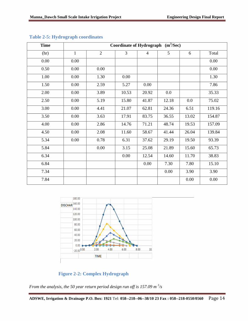
Table 2-5: Hydrograph coordinates
Time Coordinate of Hydrograph (m3/Sec)
(hr) 1 2 3 4 5 6 Total
0.00 0.00 0.00
0.50 0.00 0.00 0.00
1.00 0.00 1.30 0.00 1.30
1.50 0.00 2.59 5.27 0.00 7.86
2.00 0.00 3.89 10.53 20.92 0.0 35.33
2.50 0.00 5.19 15.80 41.87 12.18 0.0 75.02
3.00 0.00 4.41 21.07 62.81 24.36 6.51 119.16
3.50 0.00 3.63 17.91 83.75 36.55 13.02 154.87
4.00 0.00 2.86 14.76 71.21 48.74 19.53 157.09
4.50 0.00 2.08 11.60 58.67 41.44 26.04 139.84
5.34 0.00 0.78 6.31 37.62 29.19 19.50 93.39
5.84 0.00 3.15 25.08 21.89 15.60 65.73
6.34 0.00 12.54 14.60 11.70 38.83
6.84 0.00 7.30 7.80 15.10
7.34 0.00 3.90 3.90
7.84 0.00 0.00
Figure 2-2: Complex Hydrograph
From the analysis, the 50 year return period design run off is 157.09 m 3/s
Manna_Dawch Small Scale Intake Irrigation Project Engineering Design Final Report
ADSWE, Irrigation & Drainage P.O. Box: 1921 Tel: 058--218--06--38/10 23 Fax : 058--218-0550/0560 Page 15
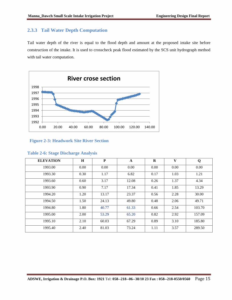
2.3.3 Tail Water Depth Computation
Tail water depth of the river is equal to the flood depth and amount at the proposed intake site before
construction of the intake. It is used to crosscheck peak flood estimated by the SCS unit hydrograph method
with tail water computation.
1992
1993
1994
1995
1996
1997
1998
0.00 20.00 40.00 60.00 80.00 100.00 120.00 140.00
River crose section
Figure 2-3: Headwork Site River Section
Table 2-6: Stage Discharge Analysis
ELEVATION H P A R V Q
1993.00 0.00 0.00 0.00 0.00 0.00 0.00
1993.30 0.30 1.17 6.82 0.17 1.03 1.21
1993.60 0.60 3.17 12.08 0.26 1.37 4.34
1993.90 0.90 7.17 17.34 0.41 1.85 13.29
1994.20 1.20 13.17 23.37 0.56 2.28 30.00
1994.50 1.50 24.13 49.80 0.48 2.06 49.71
1994.80 1.80 40.77 61.33 0.66 2.54 103.70
1995.00 2.00 53.29 65.20 0.82 2.92 157.09
1995.10 2.10 60.03 67.29 0.89 3.10 185.80
1995.40 2.40 81.03 73.24 1.11 3.57 289.50
Manna_Dawch Small Scale Intake Irrigation Project Engineering Design Final Report
ADSWE, Irrigation & Drainage P.O. Box: 1921 Tel: 058--218--06--38/10 23 Fax : 058--218-0550/0560 Page 16
0
0.5
1
1.5
2
2.5
0 20 40 60 80 100 120 140 160
Tail
Dep
th (
m)
Discharge (m3/s)
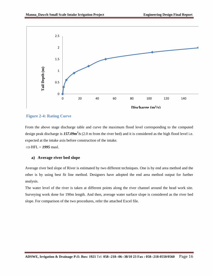
Figure 2-4: Rating Curve
From the above stage discharge table and curve the maximum flood level corresponding to the computed
design peak discharge is 157.09m3/s (2.0 m from the river bed) and it is considered as the high flood level i.e.
expected at the intake axis before construction of the intake.
HFL = 1995 masl.
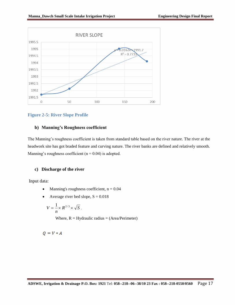
a) Average river bed slope
Average river bed slope of River is estimated by two different techniques. One is by end area method and the
other is by using best fit line method. Designers have adopted the end area method output for further
analysis.
The water level of the river is taken at different points along the river channel around the head work site.
Surveying work done for 190m length. And then, average water surface slope is considered as the river bed
slope. For comparison of the two procedures, refer the attached Excel file.
Manna_Dawch Small Scale Intake Irrigation Project Engineering Design Final Report
ADSWE, Irrigation & Drainage P.O. Box: 1921 Tel: 058--218--06--38/10 23 Fax : 058--218-0550/0560 Page 17
Figure 2-5: River Slope Profile
b) Manning’s Roughness coefficient
The Manning’s roughness coefficient is taken from standard table based on the river nature. The river at the
headwork site has got braded feature and curving nature. The river banks are defined and relatively smooth.
Manning’s roughness coefficient (n = 0.04) is adopted.
c) Discharge of the river
Input data:
Manning's roughness coefficient, n = 0.04
Average river bed slope, S = 0.018
SRn
V 3/21,
Where, R = Hydraulic radius = (Area/Perimeter)
Manna_Dawch Small Scale Intake Irrigation Project Engineering Design Final Report
ADSWE, Irrigation & Drainage P.O. Box: 1921 Tel: 058--218--06--38/10 23 Fax : 058--218-0550/0560 Page 18
Table 2-7: River Discharge Computation at Different Stages of Flow
Sr. Nr Elevation H P A R V Q
1 1993.00 0 0 0 0.00 0 0
2 1993.30 0.3 1.17 6.818 0.17 1.03 1.21
3 1993.60 0.6 3.17 12.0775 0.26 1.37 4.34
4 1993.90 0.9 7.17 17.335 0.41 1.85 13.29
5 1994.20 1.2 13.17 23.3725 0.56 2.28 30.00
6 1994.50 1.5 24.13 49.7958 0.48 2.06 49.71
7 1994.80 1.8 40.77 61.33 0.66 2.54 103.70
8 1995.00 2.00 53.29 65.20 0.82 2.92 157.09
Manna_Dawch Small Scale Intake Irrigation Project Engineering Design Final Report
ADSWE, Irrigation & Drainage P.O. Box: 1921 Tel: 058--218--06--38/10 23 Fax : 058--218-0550/0560 Page 19
3 HEADWORK DESIGN
3.1 Headwork Site Selection
Head work site selection for right side of the Menna_Dawch River is more appropriate for irrigation
development and at 4 places on the river, there are traditional diversions in the form of the intakes to irrigate
the right side of the river. All canals that emerge from the head work site creep along the right bank of the
river. These canals are exposed to the floods. The constructed traditional canal is usually taken away by flood
during rain seasons. Reconstruction has to be executed to use the water for irrigation development. This is
basic problem to the site, which has to be solved by this project.
The headwork site has been selected at the upstream of three traditional diversions to combine them for the
irrigation development.
Taking into consideration, the geological formation of the headwork site, proximity of the command area to
headwork, river topography, water head required, construction material availability, crossing structure along
the route of the main canal and expected flood intensity, intake is proposed as headwork structure.
3.2 River Geology
It is a common fact that the river development tends to accommodate itself to the local geology that develops
along the structurally weak zones like faults, joints, folds, etc. The drainage system of the study area is
strongly influenced by geological structures and formations, the nature of the vegetation cover and climate.
The nature of geological formations and structures has also strong influence on the development of the
channel.
The present morphology of the Menna River channel is a function of a number of processes and
environmental conditions, including the composition of the bed and the banks stable clay soil formation.
The size and composition of the sediment moving through the channel; the rate of sediment transport through
the channel and deposition on the banks and beds; and the regional degradation due to erosion processes.
Both left bank and the bed are composed of loose silt clay soil and coarser alluvial sediment as the result the
stream shows highly meandering nature both up and downstream from the proposed site but at the particular
intake site it shows not straight river channel. The river has wider section in upstream & downstream.
Manna_Dawch Small Scale Intake Irrigation Project Engineering Design Final Report
ADSWE, Irrigation & Drainage P.O. Box: 1921 Tel: 058--218--06--38/10 23 Fax : 058--218-0550/0560 Page 20
3.2.1 River Bed condition
The stream bed at proposed headwork site is characterized by straight, undefined and uniform surface
situations and formed with uniform geological materials, as seen from surface and subsurface observations.
Due to undefined flow direction and bank shape of the river, the stream bed has a very wide range from left
bank to right bank. This stream bed has 80m length during in the time of study and the whole surface of the
bed is covered by thick alluvial deposits, across the stream bed from right to left bank. The alluvial deposits
that cover all stream bed in both upstream and downstream direction including the intake axis. The deposit is
characterized by boulder, cobble, gravel, sand and silt formations. The test pit is taken from this stream bed
near the right bank with 3m height and from the observation of this subsurface investigation; the bed rock is
not exist at near distance. The test pit material is characterized by silty sand and gravel soil until the end of
pit depth with higher moisture content. The laboratory test has been done for this pit to characterize the
gradation of the deposit and according to laboratory testing (especially for gradation test); the deposit is
characterized by the following results:
Gravel (>4.75mm) =37.15%
Coarse sand (4.75-0.425mm) =40.25%
Fine sand (0.425-0.075mm) =16.67%
Silt and clay (<0.075mm) =5.93%
Manna_Dawch Small Scale Intake Irrigation Project Engineering Design Final Report
ADSWE, Irrigation & Drainage P.O. Box: 1921 Tel: 058--218--06--38/10 23 Fax : 058--218-0550/0560 Page 21
Figure 3-1: River Bed at the Proposed Intake Site
3.2.2 River Bank Condition
3.2.2.1 Right Bank
The right bank of the project headwork site composed from SILTY CLAY and CLAY with brown color
soils. The bank has 2m height from the river bed to upper area along the proposed axis. The main canal out
let is part of this bank and traditional canal exists in this side and the canal is during in the time of study is
functional for irrigation purpose by local people. The bank nature is undefined in both upstream and
downstream direction including the proposed axis due to less erosion resistance materials. In general the
bank has no defined shape and the river flow direction changes from season to season. There is no any type
of rock out crop in general in the banks, so that always bank erosion and sliding condition is increasing due
to year to year. From observation of bank geology and stream flow condition, the area is unstable,
unworkable and not durable, so that the area required different erosion and sliding protection structures such
that masonry or retaining wall during in the time of project construction. Along in this section of the bank the
masonry or retaining wall should be constructed within 75m and 30m in both the upstream and downstream
direction respectively, if not the river strictly changed current flow direction and the hydraulic structure that
constructed in the area is out of function.
Manna_Dawch Small Scale Intake Irrigation Project Engineering Design Final Report
ADSWE, Irrigation & Drainage P.O. Box: 1921 Tel: 058--218--06--38/10 23 Fax : 058--218-0550/0560 Page 22
3.2.2.2 Left Bank
The left bank of the project headwork site geological formation is SILTY SAND and SILTY CLAY soils in
both the upstream and downstream direction including the axis. The bank nature is gentle area and less
erosion activity resistance, so that due to this less erosion resistance material the bank shape becomes gentle
and move towards the farmland area year to year. In the last time the river could be diverted by weir structure
but from this weak nature of bank material the flow of river changed out of the weir and still the weir
structure is not functional, so that to avoid this problem the river should be diverted by intake structure and
different retaining structures are also required to protect river flow direction. The river flows has no
permanent flow direction and in summer season the flood which comes from the surrounding mountain from
the upstream direction highly affected this bank. From less erosion resistance bank material nature, this bank
required flood resistance structure such that masonry structure or retaining wall in both the upstream and
downstream direction from the axis. In both upstream and downstream direction the masonry or retaining
structures are required within 80m and 30m length respectively.
3.3 Headwork Type Selection
Considering the river geology features and expected flood amount, Intake is chosen.
Simple for construction.
Intake section is expected of the peak flood while the remaining flood will pass over the overflow
section of the river course.
There is no significant bed load (boulder effect) in the river.
3.4 Hydraulic Design of Headwork Structure
3.4.1 Intake Height or Scour Depth Determination
The following major factors have been seen in determining the Intake crest level:
Maximum command area elevation
Deriving head of the intake structure
Loss
Lowest Point of river center
Manna_Dawch Small Scale Intake Irrigation Project Engineering Design Final Report
ADSWE, Irrigation & Drainage P.O. Box: 1921 Tel: 058--218--06--38/10 23 Fax : 058--218-0550/0560 Page 23
3.4.2 Intake Dimensions
3.4.2.1 Flow over the Intake crest
a. Crest Length
Actual river section width of the over flow section of the river is = 80m
b. Discharge over the intake section
Design discharge, Q = 157.09 m3/s. (Result is obtained from hydrology report of same
document).
3.4.3 Outlet Design
3.4.3.1 Canal outlet level
The head regulator is provided on the right-side .The sill level of this head regulator is fixed from different
angle observations. The main conveyance system is more than 2.6km which passes more gullies and
undulating alignment. Hence this level is fixed based on the optimum route alignment and the maximum
irrigated command level including minor and major losses criteria. Based on this condition, the sill level is
fixed to be1992.40m.
• Outlet capacity
The minimum command area is determined by the minimum flow of the river but the canal capacity should
be determined for maximum command area and the corresponding discharge. In this case the outlet capacity
is fixed considering maximum duty and command area are considered to account the variation of duty.
Outlet capacity = Duty x command area
Where, maximum duty for 20hr irrigation 1.22 L/s/ha
Command area = 180ha.
Outlet capacity = 1.22 L/s/ha x 180ha = 220 L/sec
• Outlet size
From the intake discharge formula the outlet size is determined as follows
Q = CLHe3/2
Where; C = coeff. of discharge = 1.7
L = Length of water w
mxCHe
QL 2.0
1.07.1
22.02/32/3
Manna_Dawch Small Scale Intake Irrigation Project Engineering Design Final Report
ADSWE, Irrigation & Drainage P.O. Box: 1921 Tel: 058--218--06--38/10 23 Fax : 058--218-0550/0560 Page 24
⇒ Waterway length = 0.6m from hydraulic computation canal parameters.
Hence, provide an outlet size of 0.6mx 0.9m (length x height) by adding free board 0.30m .The gate of the
off take canal is to be vertical sheet metal of 0.7m x 0.90m for the closure of the opening space. The grooves
are to be provided on the walls using angle iron frames at the two sides of the gate openings.
3.4.3.2 Trash rack and Operation Slab
A vertical raised gate is designed for the canal outlet regulator. These gates slides over the operation slab on
the outlet of canal during opening and closing.
For easy operation of these gates, operation slab is provided. The size of the operation slab is fixed from the
point of construction and free movement. The size of the operation slab is shown in the drawing for canal
outlet thickness 0.2m.
The actual arrangement of angle irons, spindles, shafts and operation slab including other components is
shown on the design drawing. For each arrangement and further information, refer to the design drawing.
Trash rack is provided to protect the opening off take from the incoming boulders and debris. Size of trash
rack is 0.8m width and 0.9m height. Trash racks of diameter 12mm with c/c spacing of 20cm has to be
provided u/s of the gate to prevent entry of debris to the canal.
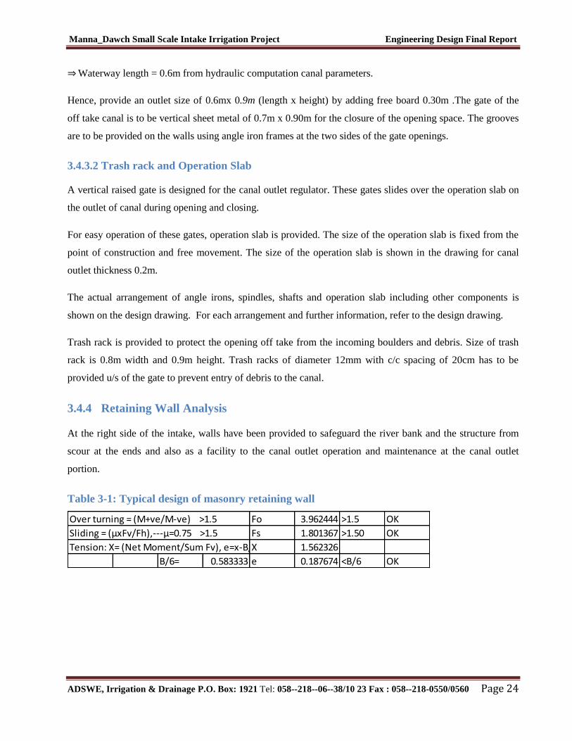
3.4.4 Retaining Wall Analysis
At the right side of the intake, walls have been provided to safeguard the river bank and the structure from
scour at the ends and also as a facility to the canal outlet operation and maintenance at the canal outlet
portion.
Table 3-1: Typical design of masonry retaining wall
Over turning = (M+ve/M-ve) >1.5 Fo 3.962444 >1.5 OK
Sliding = (µxFv/Fh),---µ=0.75 >1.5 Fs 1.801367 >1.50 OK
Tension: X= (Net Moment/Sum Fv), e=x-B/2, e<B/6X 1.562326
B/6= 0.583333 e 0.187674 <B/6 OK
Manna_Dawch Small Scale Intake Irrigation Project Engineering Design Final Report
ADSWE, Irrigation & Drainage P.O. Box: 1921 Tel: 058--218--06--38/10 23 Fax : 058--218-0550/0560 Page 25
4 IRRIGATION AND DRAINAGE SYSTEMS DESIGN
4.1 Irrigable Area Description
4.1.1 Topography
Topography is an important factor for the planning of any irrigation project as it influences method of
irrigation, drainage, erosion, mechanization, and cost of land development, labor requirement and choice of
crops.
The topographic feature of the project command area is mainly mild sloping type. Its elevation range is from
1991 to1936 meters above sea level. Nevertheless, it requires soil and water conservation measures or
structures (i.e. constructing bunds, bio-physicals, check dams, artificial water ways, etc).
The project command area is situated at the right side of Menna River (to the west side of the river). The
natural topographic feature of the command area has inclined from the North- to the North-West direction.
4.1.2 Soil characteristics
Soil properties (physical, chemical, etc.) greatly influence the growth and thereby yield of crops which is
grown. The command area has predominantly silt and clay and silt sand soil textured. Soils of the command
area are suitable for most of the selected crops to be grown (for further detail see the Agronomy Study of the
same project.
4.2 Irrigation Water Requirement
4.2.1 Crop Water Requirement (CWR)
The calculation of crop water requirement is a very important aspect for planning of any irrigation project.
Several methods and procedures are available for this. The Food and Agriculture Organization (FAO) of the
United Nations has also made available several publications on this subject and other issues related with this.
The computer program available in FAO Irrigation and Drainage Paper No. 56 “CROPWAT” has been used
for the calculation of Crop Water requirement. This program is based on Penman-Monteith approach and
procedures for calculation of crop water requirements and irrigation requirements are mainly based on
methodologies presented in FAO Irrigation and Drainage Paper No. 24 “Crop Water Requirements” and No.
33 “Yield Response to Water”.
Manna_Dawch Small Scale Intake Irrigation Project Engineering Design Final Report
ADSWE, Irrigation & Drainage P.O. Box: 1921 Tel: 058--218--06--38/10 23 Fax : 058--218-0550/0560 Page 26
The corresponding values of the crop water requirements of the proposed crops of the project are presented
in the Agronomy Study of the same project.
4.2.2 Irrigation efficiency (Ep)
To complete the evaluation of the demand, the efficiency of the water distribution system and of application
must be known.
The gross requirement of water for irrigation system is very much dependent on the overall efficiency of the
irrigation system, which in turn is dependent on several factors: Method of irrigation, type of canal (Lined
and/or Unlined), method of operations (simultaneously and continuous or Rotational water supply), and
availability of structures (for controlling and distribution and measuring and monitoring).
On the basis of these factors, the project has planned to impose surface irrigation method (using furrows).
The canal system is unlined other than canal near the head work. Hence, the conveyance efficiency has been
estimated to be 90%, distribution efficiency 85%, and field application efficiency 60%. As a result of these
the overall irrigation efficiency has been estimated to be 46%. According to soil Lab result, soils of the
command area are predominantly characterized as silt sand soils.
4.2.3 Irrigation duty
Irrigation duty is the volume of water required per hectare for the full flange of the crops. Moreover, it helps
in designing an efficient irrigation canal system.
The area, which will be irrigated, can be calculated by knowing the total available water at the source and
the overall duty for all crops required to be irrigated in different seasons of the years.
The proposed cropping pattern of Menna_Dawch intake irrigation project has showed a maximum net
irrigation water requirement (NIWR) in the month of March with the amount of 5.88mm/day for 24 working
hours (for overall proposed crops).
However, for the designing of the irrigation water application and the flows in the entire canal systems, from
the overall proposed crops the one that has maximum NIWR was used for irrigation duty calculation.
Accordingly, potato has showed the maximum NIWR (i.e. 5.88mm/day); and hence taken for the irrigation
project duty calculation as indicated here below:
For Menna_Dawch River Intake Irrigation Project, it decided to adopt 60% field application efficiency, 85%
distribution efficiency, and 90% conveyance efficiency as the soil is clay textured and the canal systems are
estimated to be line and unlined except small portion of the main canal near head work. Hence, the
Manna_Dawch Small Scale Intake Irrigation Project Engineering Design Final Report
ADSWE, Irrigation & Drainage P.O. Box: 1921 Tel: 058--218--06--38/10 23 Fax : 058--218-0550/0560 Page 27
overall/project efficiency for the selected surface irrigation method has been estimated to be 46%
(60/100*90/100*85/100) which is rounded to 46%.
For the designing of the project, the GIWR is given as follows:
GIWR = 5.88/0.460 = 12.78 [mm/day]
The GIWR, 12.78 mm/day, represents the daily quantity of water that is required to be applied. This water
quantity is also used for the determination of the canal discharge in consideration of the time of flow and is
defined as the duty, expressed as l/s/ha.
The duty is calculated by:
Duty (D) = GIWR × 1000 × 10 / (t × 60×60)
Where; Duty – the duty [l/s/ha]
GIWR – Gross Irrigation Requirement [mm/day]
t – Daily irrigation or flow hours [hrs]
The duty for the GIWR of 12.78mm/day and20 hours of daily irrigation time (t = 20), is supported to be used
with furrow irrigation method. Hence, Duty for20 working hours, as the site is nearer to farmers’ village and
local farmers have experiences in irrigation, is computed as follows:
D = (12.78 x 1000 x 10) / (20 x 3600) =1.22L/S/ha
4.2.4 Irrigation Methods
Among the different irrigation systems furrow irrigation system is proposed for the project area; and the
irrigation water will be obtained from Menna River and by constructing intake and convoying the water
commonly through lined and earthen canals (MC, SC, and TC) and then leading to field canals; and finally
irrigation takes place mostly in furrows.
For this project, among the various irrigation methods, surface irrigation method has been selected. Of the
surface irrigation methods furrow, border and basin irrigation methods can be used to supply irrigation water
to the plants/crops. However, each method has its own advantages and disadvantages. Care should be taken
when choosing the method which is best suited to the local circumstances, i.e., depending on slopes, soil
types, selected crop types, amount of water available, etc. of the command area.
Manna_Dawch Small Scale Intake Irrigation Project Engineering Design Final Report
ADSWE, Irrigation & Drainage P.O. Box: 1921 Tel: 058--218--06--38/10 23 Fax : 058--218-0550/0560 Page 28
Based on the above factors surface irrigation method has been proposed for the proposed crops in this
project. The method allows applying light irrigation and can be laid out in sloping fields along the contour.
Furrow irrigation method is best suited for most of the proposed and row planted crops. In general, furrow
irrigation method is simple, Manageable and widely practiced irrigation method. This method is suitable for
row crops that cannot stand in water for long periods. The only thing required to use this method is row
planting of crops. Besides, basin and border irrigation method would be used for the non-row planted crops.
Rotational flow water distribution is also recommended for the project area.
4.3 Irrigation and Drainage System Layout
The irrigation system layout for the project is prepared taking the following points into consideration besides
other factors.
A primary concern in the layout of the system is that it serves the purpose of conveying and
distributing water to the command area.
The excavation and earth fill volumes not be excessive, otherwise the construction costs can be
tremendous.
The selection of longitudinal bed slope is made taking into account the existing slopes of the terrain,
so as to minimize deviations in canal routing.
Curves in canals should not be too sharp.
The proposed irrigation system layout comprises one main canal, four secondary canals and twelve tertiary
canals as shown on the layout Drawings. The main canal runs for most of its length parallel to the contours
and several changes of direction are necessary to follow the topography. It crosses four main gullies, one foot
path. The main canal is masonry lined for a length of 2600meters starting from the intake outlet.
Conveyance System
The conveyance system consists of one Main canal to irrigate total command area of 180ha. The main canal
starts from Water abstraction site on right side and conveys water for a length of 2.6 Km.
Main canal is aligned along contours and supplies to four secondary unit and two turn out.
Design of the Canal System
Flow Depth and Section Capacity
The earthen canals have been designed with a trapezoidal shape and the lined ones with rectangular x-section
using Manning's Formula:
Manna_Dawch Small Scale Intake Irrigation Project Engineering Design Final Report
ADSWE, Irrigation & Drainage P.O. Box: 1921 Tel: 058--218--06--38/10 23 Fax : 058--218-0550/0560 Page 29
n
xSAxRQ
2/13/2
Where Q = discharge (m3/s)
R = Hydraulic radius (Flow area/wetted perimeter)
S = Hydraulic gradient
n = Manning's roughness coefficient, n = 0.025 is for the earth channels and n = 0.018 for
the masonry lined part of the main canal
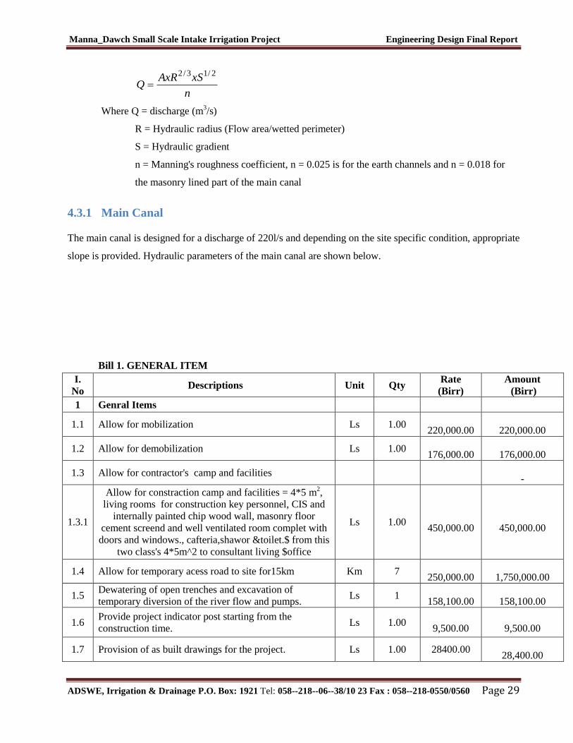
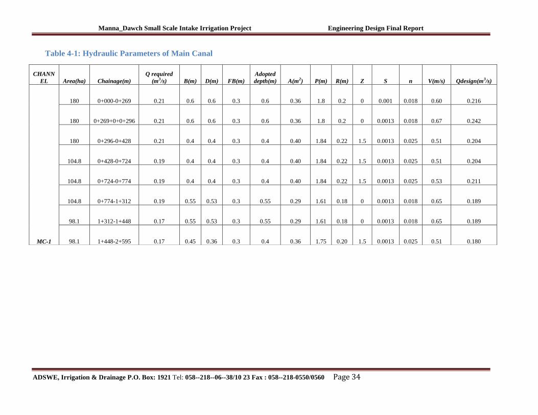
4.3.1 Main Canal
The main canal is designed for a discharge of 220l/s and depending on the site specific condition, appropriate
slope is provided. Hydraulic parameters of the main canal are shown below.
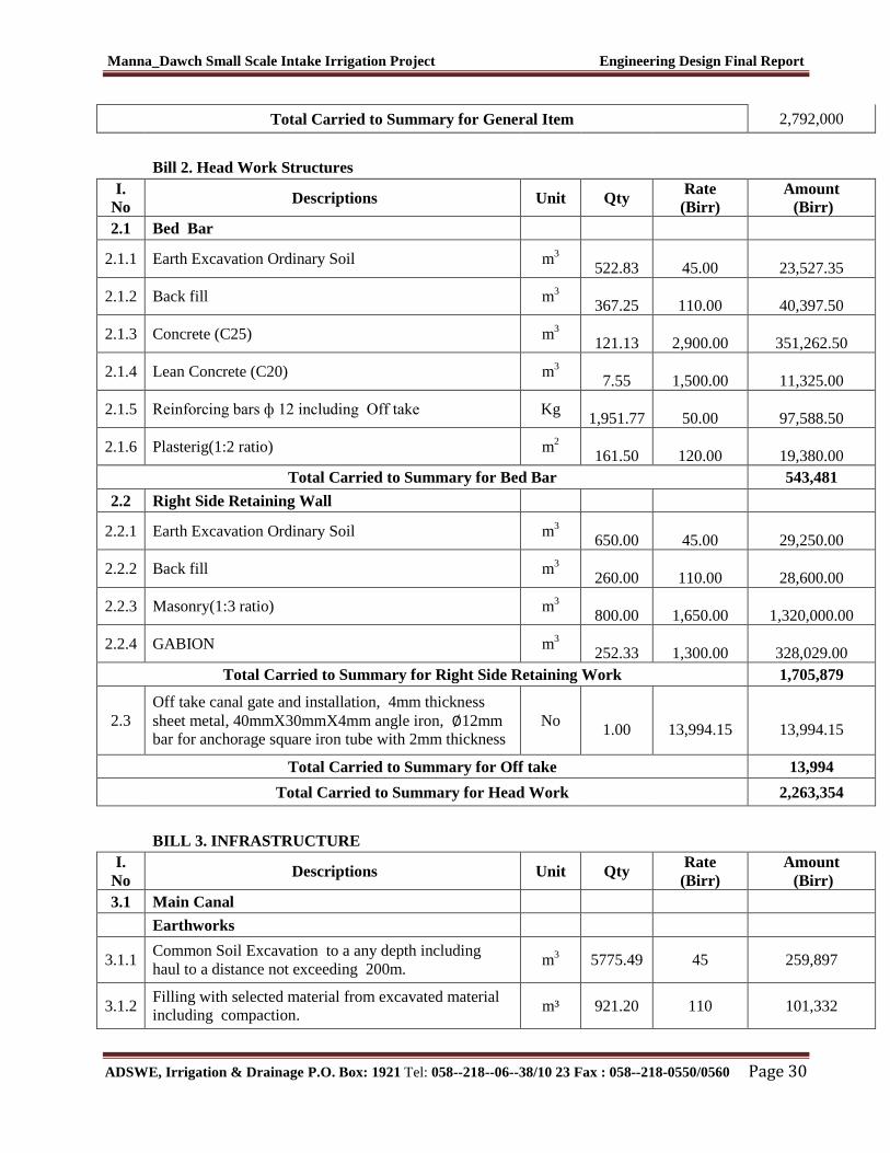
Bill 1. GENERAL ITEM
I.
No Descriptions Unit Qty
Rate
(Birr)
Amount
(Birr)
1 Genral Items
1.1 Allow for mobilization Ls 1.00
220,000.00
220,000.00
1.2 Allow for demobilization Ls 1.00
176,000.00
176,000.00
1.3 Allow for contractor's camp and facilities
-
1.3.1
Allow for constraction camp and facilities = 4*5 m2,
living rooms for construction key personnel, CIS and
internally painted chip wood wall, masonry floor
cement screend and well ventilated room complet with
doors and windows., cafteria,shawor &toilet.$ from this
two class's 4*5m^2 to consultant living $office
Ls 1.00
450,000.00
450,000.00
1.4 Allow for temporary acess road to site for15km Km 7
250,000.00
1,750,000.00
1.5 Dewatering of open trenches and excavation of
temporary diversion of the river flow and pumps. Ls 1
158,100.00
158,100.00
1.6 Provide project indicator post starting from the
construction time. Ls 1.00
9,500.00
9,500.00
1.7 Provision of as built drawings for the project. Ls 1.00 28400.00
28,400.00
Manna_Dawch Small Scale Intake Irrigation Project Engineering Design Final Report
ADSWE, Irrigation & Drainage P.O. Box: 1921 Tel: 058--218--06--38/10 23 Fax : 058--218-0550/0560 Page 30
Total Carried to Summary for General Item 2,792,000
Bill 2. Head Work Structures
I.
No Descriptions Unit Qty
Rate
(Birr)
Amount
(Birr)
2.1 Bed Bar
2.1.1 Earth Excavation Ordinary Soil m3
522.83
45.00
23,527.35
2.1.2 Back fill m3
367.25
110.00
40,397.50
2.1.3 Concrete (C25) m3
121.13
2,900.00
351,262.50
2.1.4 Lean Concrete (C20) m3
7.55
1,500.00
11,325.00
2.1.5 Reinforcing bars ф 12 including Off take Kg
1,951.77
50.00
97,588.50
2.1.6 Plasterig(1:2 ratio) m2
161.50
120.00
19,380.00
Total Carried to Summary for Bed Bar 543,481
2.2 Right Side Retaining Wall
2.2.1 Earth Excavation Ordinary Soil m3
650.00
45.00
29,250.00
2.2.2 Back fill m3
260.00
110.00
28,600.00
2.2.3 Masonry(1:3 ratio) m3
800.00
1,650.00
1,320,000.00
2.2.4 GABION m3
252.33
1,300.00
328,029.00
Total Carried to Summary for Right Side Retaining Work 1,705,879
2.3
Off take canal gate and installation, 4mm thickness
sheet metal, 40mmX30mmX4mm angle iron, ∅12mm
bar for anchorage square iron tube with 2mm thickness
No
1.00
13,994.15
13,994.15
Total Carried to Summary for Off take 13,994
Total Carried to Summary for Head Work 2,263,354
BILL 3. INFRASTRUCTURE
I.
No Descriptions Unit Qty
Rate
(Birr)
Amount
(Birr)
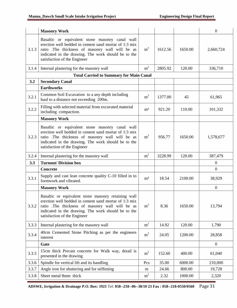
3.1 Main Canal
Earthworks
3.1.1 Common Soil Excavation to a any depth including
haul to a distance not exceeding 200m. m
3 5775.49 45 259,897
3.1.2 Filling with selected material from excavated material
including compaction. m³ 921.20 110 101,332
Manna_Dawch Small Scale Intake Irrigation Project Engineering Design Final Report
ADSWE, Irrigation & Drainage P.O. Box: 1921 Tel: 058--218--06--38/10 23 Fax : 058--218-0550/0560 Page 31
Masonry Work 0
3.1.3
Basaltic or equivalent stone masonry canal wall
erection well bedded in cement sand mortar of 1:3 mix
ratio .The thickness of masonry wall will be as
indicated in the drawing. The work should be to the
satisfaction of the Engineer
m3 1612.56 1650.00 2,660,724
3.1.4 Internal plastering for the masonry wall m2 2805.92 120.00 336,710
Total Carried to Summary for Main Canal
3.2 Secondary Canal
Earthworks
3.2.1 Common Soil Excavation to a any depth including
haul to a distance not exceeding 200m. m
3 1377.00 45 61,965
3.2.2 Filling with selected material from excavated material
including compaction. m³ 921.20 110.00 101,332
Masonry Work
3.2.3
Basaltic or equivalent stone masonry canal wall
erection well bedded in cement sand mortar of 1:3 mix
ratio .The thickness of masonry wall will be as
indicated in the drawing. The work should be to the
satisfaction of the Engineer
m3 956.77 1650.00 1,578,677
3.2.4 Internal plastering for the masonry wall m2 3228.99 120.00 387,479
3.3 Turnout/ Division box 0
Concrete 0
3.3.1 Supply and cast lean concrete quality C-10 filled in to
formwork and vibrated. m³ 18.54 2100.00 38,929
Masonry Work 0
3.3.2
Basaltic or equivalent stone masonry retaining wall
erection well bedded in cement sand mortar of 1:3 mix
ratio .The thickness of masonry wall will be as
indicated in the drawing. The work should be to the
satisfaction of the Engineer
m3 8.36 1650.00 13,794
3.3.3 Internal plastering for the masonry wall m2 14.92 120.00 1,790
3.3.4 40cm Cemented Stone Pitching as per the engineers
interest m
3 24.05 1200.00 28,858
Gate 0
3.3.5 15cm thick Precast concrete for Walk way, detail is
presented in the drawing m
2 152.60 400.00 61,040
3.3.6 Spindle for vertical lift and its handling Pcs 35.00 6000.00 210,000
3.3.7 Angle iron for shuttering and for stiffening m 24.66 800.00 19,728
3.3.8 Sheet metal 8mm thick m2 2.32 1000.00 2,320
Manna_Dawch Small Scale Intake Irrigation Project Engineering Design Final Report
ADSWE, Irrigation & Drainage P.O. Box: 1921 Tel: 058--218--06--38/10 23 Fax : 058--218-0550/0560 Page 32
3.4 Drop structure 0
Concrete 0
3.4.1 Supply and cast lean concrete quality C-10 filled in to
formwork and vibrated. m³ 3.79 2100.00 7,959
Masonry Work 0
3.4.2
Basaltic or equivalent stone masonry retaining wall
erection well bedded in cement sand mortar of 1:3 mix
ratio .The thickness of masonry wall will be as
indicated in the drawing. The work should be to the
satisfaction of the Engineer
m3 20.56 1650.00 33,924
3.4.3 Internal plastering for the masonry wall m2 51.40 120.00 6,168
3.4.4 40cm Cemented Stone Pitching as per the engineers
interest m
3 21.09 1200.00 25,308
Total Carried to Summary for Secondary Canals 0
3.5 Tertiary Canal Earthworks 0
3.5.1
Common Soil Excavation in trapezoidal Canal to a any
depth including haul to a distance not exceeding
200m.
m3 526.6 60 31,596
3.5.2
Filling with selected material from borrow pits
including compaction (hauling distance not exceeding
5km)
m³ 1294.7 110 142,421
Total Carried to Summary for Tertiary Canals 0
3.6 Flume 0
3.6.1 Common Soil Excavation to a any depth including
haul to a distance not exceeding 200m m3 48.0 45 2,160
Masonry Work 0
3.6.2
Basaltic or equivalent stone masonry retaining wall
erection well bedded in cement sand mortar of 1:3 mix
ratio .The thickness of masonry wall will be as
indicated in the drawing. The work should be to the
satisfaction of the Engineer
m3 24.0 1650 39,600
Concrete 0
3.6.3 Supply and cast mass concrete quality C-20 filled in to
formwork and vibrated. m3 20.3 2500 50,641
Reinforcement 0
3.6.4 dia 14 kg 219.8 50 10,991
3.6.5 dia 12 kg 225.4 50 11,270
Total Carried to Summary for Flume 0
3.7 Supper passage 0
Masonry Work 0
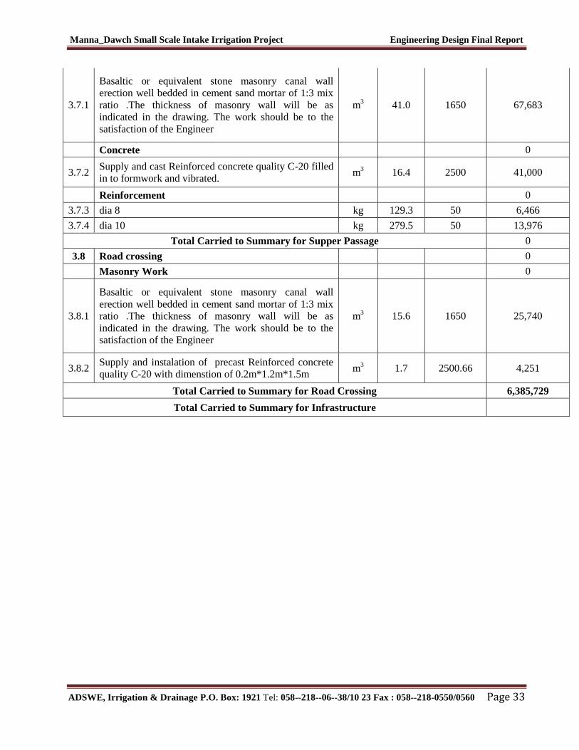
Manna_Dawch Small Scale Intake Irrigation Project Engineering Design Final Report
ADSWE, Irrigation & Drainage P.O. Box: 1921 Tel: 058--218--06--38/10 23 Fax : 058--218-0550/0560 Page 33
3.7.1
Basaltic or equivalent stone masonry canal wall
erection well bedded in cement sand mortar of 1:3 mix
ratio .The thickness of masonry wall will be as
indicated in the drawing. The work should be to the
satisfaction of the Engineer
m3 41.0 1650 67,683
Concrete 0
3.7.2 Supply and cast Reinforced concrete quality C-20 filled
in to formwork and vibrated. m
3 16.4 2500 41,000
Reinforcement 0
3.7.3 dia 8 kg 129.3 50 6,466
3.7.4 dia 10 kg 279.5 50 13,976
Total Carried to Summary for Supper Passage 0
3.8 Road crossing 0
Masonry Work 0
3.8.1
Basaltic or equivalent stone masonry canal wall
erection well bedded in cement sand mortar of 1:3 mix
ratio .The thickness of masonry wall will be as
indicated in the drawing. The work should be to the
satisfaction of the Engineer
m3 15.6 1650 25,740
3.8.2 Supply and instalation of precast Reinforced concrete
quality C-20 with dimenstion of 0.2m*1.2m*1.5m m
3 1.7 2500.66 4,251
Total Carried to Summary for Road Crossing 6,385,729
Total Carried to Summary for Infrastructure
Manna_Dawch Small Scale Intake Irrigation Project Engineering Design Final Report
ADSWE, Irrigation & Drainage P.O. Box: 1921 Tel: 058--218--06--38/10 23 Fax : 058--218-0550/0560 Page 34
Table 4-1: Hydraulic Parameters of Main Canal
CHANN
EL Area(ha) Chainage(m)
Q required
(m3/s) B(m) D(m) FB(m)
Adopted
depth(m) A(m2) P(m) R(m) Z S n V(m/s) Qdesign(m3/s)
MC-1
180 0+000-0+269 0.21 0.6 0.6 0.3 0.6 0.36 1.8 0.2 0 0.001 0.018 0.60 0.216
180 0+269+0+0+296 0.21 0.6 0.6 0.3 0.6 0.36 1.8 0.2 0 0.0013 0.018 0.67 0.242
180 0+296-0+428 0.21 0.4 0.4 0.3 0.4 0.40 1.84 0.22 1.5 0.0013 0.025 0.51 0.204
104.8 0+428-0+724 0.19 0.4 0.4 0.3 0.4 0.40 1.84 0.22 1.5 0.0013 0.025 0.51 0.204
104.8 0+724-0+774 0.19 0.4 0.4 0.3 0.4 0.40 1.84 0.22 1.5 0.0013 0.025 0.53 0.211
104.8 0+774-1+312 0.19 0.55 0.53 0.3 0.55 0.29 1.61 0.18 0 0.0013 0.018 0.65 0.189
98.1 1+312-1+448 0.17 0.55 0.53 0.3 0.55 0.29 1.61 0.18 0 0.0013 0.018 0.65 0.189
98.1 1+448-2+595 0.17 0.45 0.36 0.3 0.4 0.36 1.75 0.20 1.5 0.0013 0.025 0.51 0.180
Manna_Dawch Small Scale Intake Irrigation Project Engineering Design Final Report
ADSWE, Irrigation & Drainage P.O. Box: 1921 Tel: 058--218--06--38/10 23 Fax : 058--218-0550/0560 Page 35
4.3.2 Secondary Canals
Table 4-2: Hydraulic Parameters of secondary canals
Channel Area(ha) Chainage(m)
Q
required(m3/s) B(m) D(m) FB(m)
Adopted
B(m)
Adopted
D(m) A(m2) P(m) R(m) Z S n V(m/s) Qdesign(m3/s)
SC1-1 9.45
0+00-0+40
0.01673
0.2 0.1 0.3 0.3 0.1 0.02 0.4 0.1 0 0.01429 0.018 0.9012 0.018024
0+40-0+107 0.2 0.1 0.3 0.3 0.1 0.02 0.4 0.1 0 0.02273 0.018 1.14 0.022734
0+107-0+244 0.2 0.1 0.3 0.3 0.1 0.02 0.4 0.1 0 0.01961 0.018 1.06 0.021116
SC2-1
27.28 0+0-0+257 0.04829 0.2 0.15 0.3 0.3 0.15 0.03 0.5 0.1 0 0.03571 0.018 1.61 0.048273
18.57 0+257-0+323 0.03287 0.2 0.2 0.3 0.3 0.2 0.04 0.6 0.1 0 0.02041 0.018 1.30 0.052195
18.57 0+323-0+382 0.03287 0.3 0.25 0.4 0.3 0.25 0.075 0.8 0.1 0 0.02 0.018 1.62 0.121605
18.57 0+382-0+572 0.03287 0.2 0.15 0.3 0.3 0.15 0.03 0.5 0.1 0 0.04 0.018 1.70 0.051087
SC3-1
71.6 0+00-0+290 0.12673 0.25 0.21 0.3 0.3 0.2 0.0525 0.67 0.1 0 0.05556 0.018 2.40 0.125885
62.5 0+290-0+410 0.11063 0.25 0.25 0.3 0.3 0.25 0.0625 0.75 0.1 0 0.03846 0.018 2.08 0.129917
50.63 0+410-0+560 0.08962 0.3 0.2 0.3 0.3 0.3 0.06 0.7 0.1 0 0.0303 0.018 1.88 0.112804
36.35 0+560-0+620 0.05016 0.3 0.2 0.3 0.3 0.3 0.06 0.7 0.1 0 0.04 0.018 2.16 0.129602
18.23 0+620-873 0.02516 0.25 0.21 0.3 0.3 0.25 0.0525 0.67 0.1 0 0.04 0.018 2.03 0.106817
Manna_Dawch Small Scale Intake Irrigation Project Engineering Design Final Report
ADSWE, Irrigation & Drainage P.O. Box: 1921 Tel: 058--218--06--38/10 23 Fax : 058--218-0550/0560 Page 36
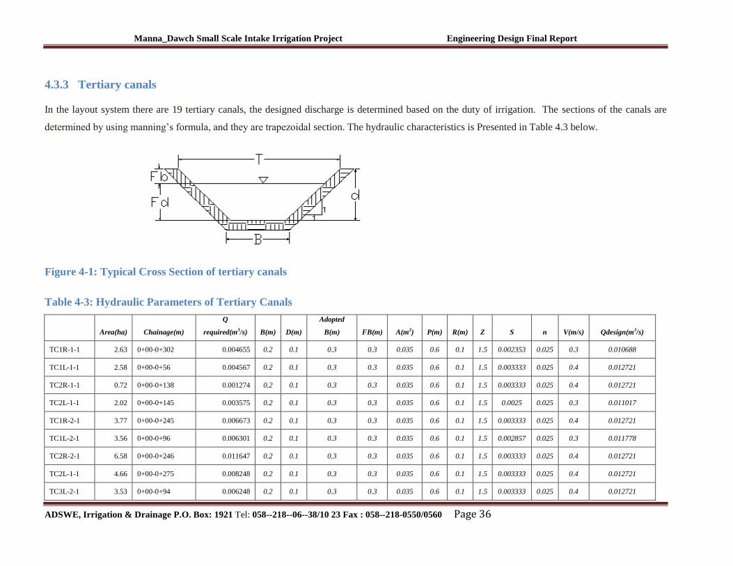
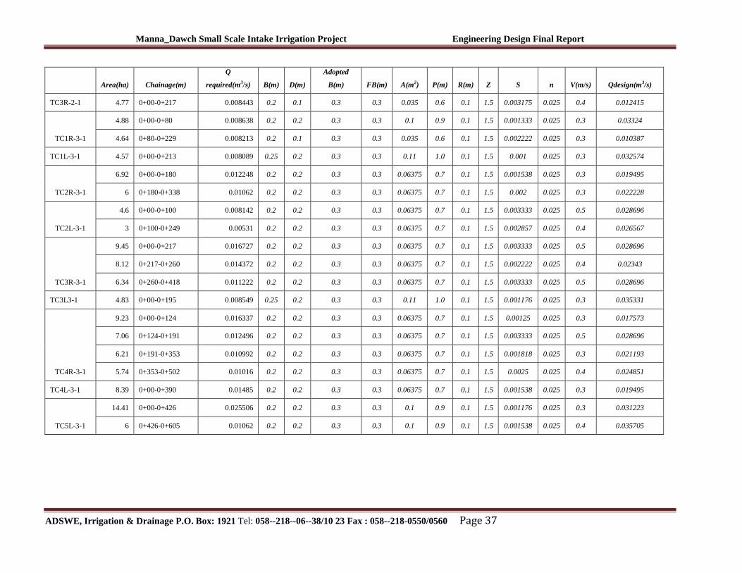
4.3.3 Tertiary canals
In the layout system there are 19 tertiary canals, the designed discharge is determined based on the duty of irrigation. The sections of the canals are
determined by using manning’s formula, and they are trapezoidal section. The hydraulic characteristics is Presented in Table 4.3 below.
Figure 4-1: Typical Cross Section of tertiary canals
Table 4-3: Hydraulic Parameters of Tertiary Canals
Area(ha) Chainage(m)
Q
required(m3/s) B(m) D(m)
Adopted
B(m) FB(m) A(m2) P(m) R(m) Z S n V(m/s) Qdesign(m3/s)
TC1R-1-1 2.63 0+00-0+302 0.004655 0.2 0.1 0.3 0.3 0.035 0.6 0.1 1.5 0.002353 0.025 0.3 0.010688
TC1L-1-1 2.58 0+00-0+56 0.004567 0.2 0.1 0.3 0.3 0.035 0.6 0.1 1.5 0.003333 0.025 0.4 0.012721
TC2R-1-1 0.72 0+00-0+138 0.001274 0.2 0.1 0.3 0.3 0.035 0.6 0.1 1.5 0.003333 0.025 0.4 0.012721
TC2L-1-1 2.02 0+00-0+145 0.003575 0.2 0.1 0.3 0.3 0.035 0.6 0.1 1.5 0.0025 0.025 0.3 0.011017
TC1R-2-1 3.77 0+00-0+245 0.006673 0.2 0.1 0.3 0.3 0.035 0.6 0.1 1.5 0.003333 0.025 0.4 0.012721
TC1L-2-1 3.56 0+00-0+96 0.006301 0.2 0.1 0.3 0.3 0.035 0.6 0.1 1.5 0.002857 0.025 0.3 0.011778
TC2R-2-1 6.58 0+00-0+246 0.011647 0.2 0.1 0.3 0.3 0.035 0.6 0.1 1.5 0.003333 0.025 0.4 0.012721
TC2L-1-1 4.66 0+00-0+275 0.008248 0.2 0.1 0.3 0.3 0.035 0.6 0.1 1.5 0.003333 0.025 0.4 0.012721
TC3L-2-1 3.53 0+00-0+94 0.006248 0.2 0.1 0.3 0.3 0.035 0.6 0.1 1.5 0.003333 0.025 0.4 0.012721
Manna_Dawch Small Scale Intake Irrigation Project Engineering Design Final Report
ADSWE, Irrigation & Drainage P.O. Box: 1921 Tel: 058--218--06--38/10 23 Fax : 058--218-0550/0560 Page 37
Area(ha) Chainage(m)
Q
required(m3/s) B(m) D(m)
Adopted
B(m) FB(m) A(m2) P(m) R(m) Z S n V(m/s) Qdesign(m3/s)
TC3R-2-1 4.77 0+00-0+217 0.008443 0.2 0.1 0.3 0.3 0.035 0.6 0.1 1.5 0.003175 0.025 0.4 0.012415
TC1R-3-1
4.88 0+00-0+80 0.008638 0.2 0.2 0.3 0.3 0.1 0.9 0.1 1.5 0.001333 0.025 0.3 0.03324
4.64 0+80-0+229 0.008213 0.2 0.1 0.3 0.3 0.035 0.6 0.1 1.5 0.002222 0.025 0.3 0.010387
TC1L-3-1 4.57 0+00-0+213 0.008089 0.25 0.2 0.3 0.3 0.11 1.0 0.1 1.5 0.001 0.025 0.3 0.032574
TC2R-3-1
6.92 0+00-0+180 0.012248 0.2 0.2 0.3 0.3 0.06375 0.7 0.1 1.5 0.001538 0.025 0.3 0.019495
6 0+180-0+338 0.01062 0.2 0.2 0.3 0.3 0.06375 0.7 0.1 1.5 0.002 0.025 0.3 0.022228
TC2L-3-1
4.6 0+00-0+100 0.008142 0.2 0.2 0.3 0.3 0.06375 0.7 0.1 1.5 0.003333 0.025 0.5 0.028696
3 0+100-0+249 0.00531 0.2 0.2 0.3 0.3 0.06375 0.7 0.1 1.5 0.002857 0.025 0.4 0.026567
TC3R-3-1
9.45 0+00-0+217 0.016727 0.2 0.2 0.3 0.3 0.06375 0.7 0.1 1.5 0.003333 0.025 0.5 0.028696
8.12 0+217-0+260 0.014372 0.2 0.2 0.3 0.3 0.06375 0.7 0.1 1.5 0.002222 0.025 0.4 0.02343
6.34 0+260-0+418 0.011222 0.2 0.2 0.3 0.3 0.06375 0.7 0.1 1.5 0.003333 0.025 0.5 0.028696
TC3L3-1 4.83 0+00-0+195 0.008549 0.25 0.2 0.3 0.3 0.11 1.0 0.1 1.5 0.001176 0.025 0.3 0.035331
TC4R-3-1
9.23 0+00-0+124 0.016337 0.2 0.2 0.3 0.3 0.06375 0.7 0.1 1.5 0.00125 0.025 0.3 0.017573
7.06 0+124-0+191 0.012496 0.2 0.2 0.3 0.3 0.06375 0.7 0.1 1.5 0.003333 0.025 0.5 0.028696
6.21 0+191-0+353 0.010992 0.2 0.2 0.3 0.3 0.06375 0.7 0.1 1.5 0.001818 0.025 0.3 0.021193
5.74 0+353-0+502 0.01016 0.2 0.2 0.3 0.3 0.06375 0.7 0.1 1.5 0.0025 0.025 0.4 0.024851
TC4L-3-1 8.39 0+00-0+390 0.01485 0.2 0.2 0.3 0.3 0.06375 0.7 0.1 1.5 0.001538 0.025 0.3 0.019495
TC5L-3-1
14.41 0+00-0+426 0.025506 0.2 0.2 0.3 0.3 0.1 0.9 0.1 1.5 0.001176 0.025 0.3 0.031223
6 0+426-0+605 0.01062 0.2 0.2 0.3 0.3 0.1 0.9 0.1 1.5 0.001538 0.025 0.4 0.035705
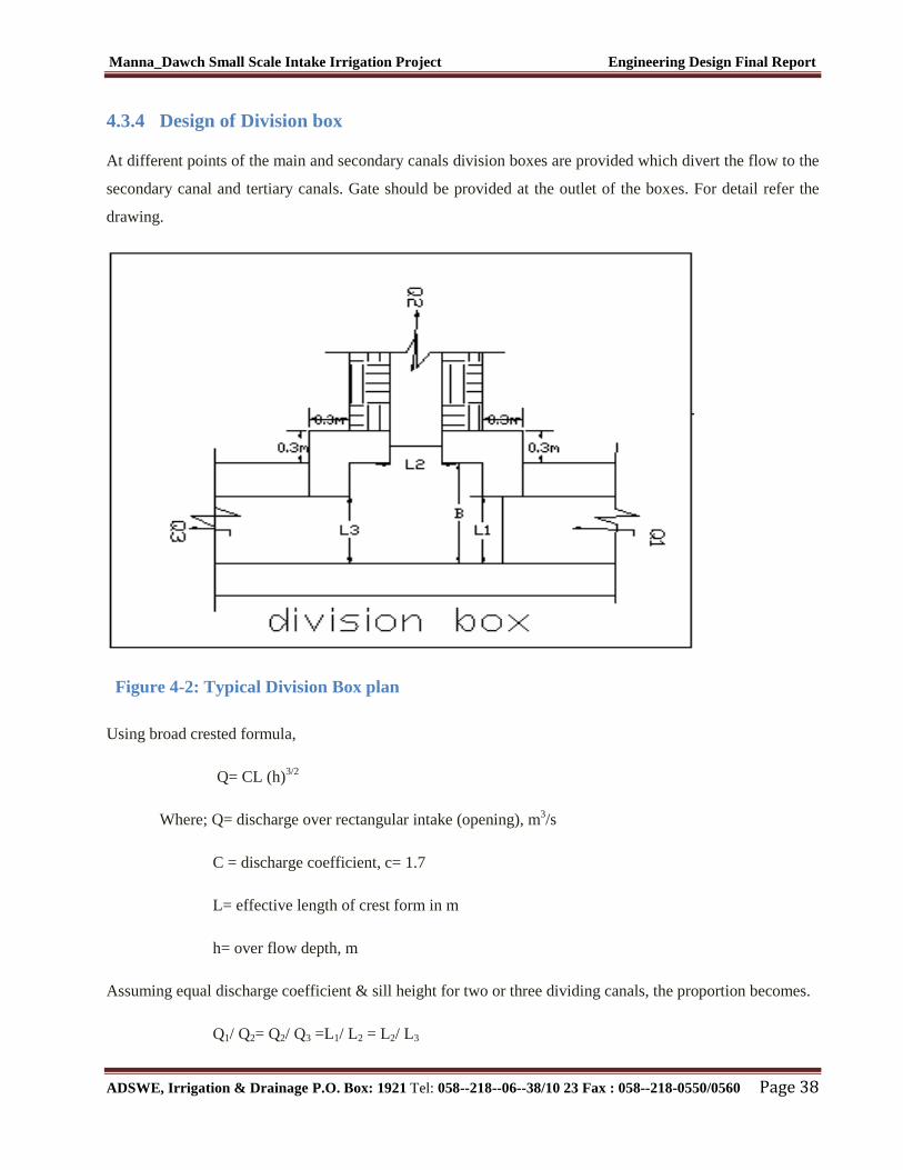
Manna_Dawch Small Scale Intake Irrigation Project Engineering Design Final Report
ADSWE, Irrigation & Drainage P.O. Box: 1921 Tel: 058--218--06--38/10 23 Fax : 058--218-0550/0560 Page 38
4.3.4 Design of Division box
At different points of the main and secondary canals division boxes are provided which divert the flow to the
secondary canal and tertiary canals. Gate should be provided at the outlet of the boxes. For detail refer the
drawing.
Figure 4-2: Typical Division Box plan
Using broad crested formula,
Q= CL (h)3/2
Where; Q= discharge over rectangular intake (opening), m3/s
C = discharge coefficient, c= 1.7
L= effective length of crest form in m
h= over flow depth, m
Assuming equal discharge coefficient & sill height for two or three dividing canals, the proportion becomes.
Q1/ Q2= Q2/ Q3 =L1/ L2 = L2/ L3

Manna_Dawch Small Scale Intake Irrigation Project Engineering Design Final Report
ADSWE, Irrigation & Drainage P.O. Box: 1921 Tel: 058--218--06--38/10 23 Fax : 058--218-0550/0560 Page 39
Where Q1= is flow in canal 1
Q2 = is flow in canal 2
Q3 = is flow in canal 3
L1= is effective crest length of intake sill across opening to canal 1
L2= is effective crest length of intake sill across opening to canal 2
L3 = is effective crest length of intake sill across opening to canal 3
Q1= CL1 (h) 3/2
,
L1 = Q1/Ch3/2
L2 = L1*Q2/ Q1
L3 = L1*Q3/ Q1
The depth of (height of) the division box,
D = d + fb
The width of the division box,
B = b + 2*m*D
D = total canal depth of the incoming canal
B =Width of Incoming Canal
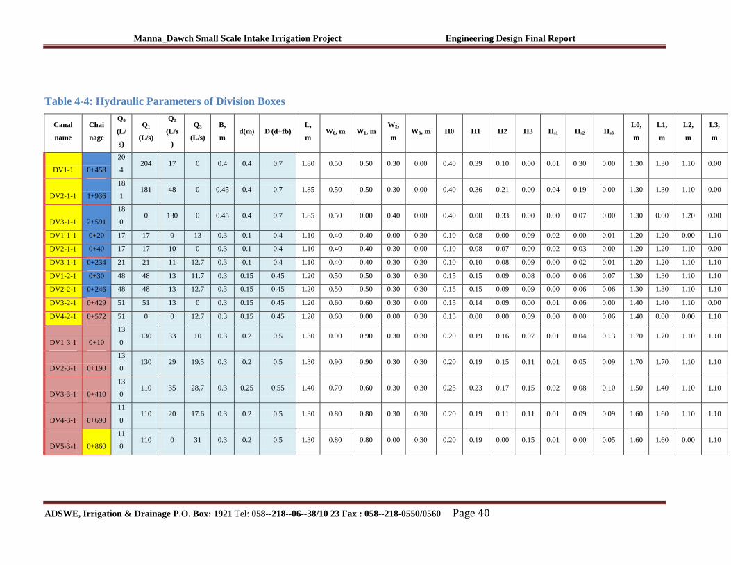
Manna_Dawch Small Scale Intake Irrigation Project Engineering Design Final Report
ADSWE, Irrigation & Drainage P.O. Box: 1921 Tel: 058--218--06--38/10 23 Fax : 058--218-0550/0560 Page 40
Table 4-4: Hydraulic Parameters of Division Boxes
Canal
name
Chai
nage
Q00
((LL//
ss))
Q11
((LL//ss))
Q22
((LL//ss
))
Q33
((LL//ss))
B,
m d(m) D ((dd++ffbb))
L,
m W00,, mm W11,, mm
W22,,
mm W33,, mm H0 H1 H2 H3 Hs1 Hs2 Hs3
L0,
m
L1,
m
L2,
m
L3,
m
DV1-1 0+458
20
4 204 17 0 0.4 0.4 0.7 1.80 0.50 0.50 0.30 0.00 0.40 0.39 0.10 0.00 0.01 0.30 0.00 1.30 1.30 1.10 0.00
DV2-1-1 1+936
18
1 181 48 0 0.45 0.4 0.7 1.85 0.50 0.50 0.30 0.00 0.40 0.36 0.21 0.00 0.04 0.19 0.00 1.30 1.30 1.10 0.00
DV3-1-1 2+591
18
0 0 130 0 0.45 0.4 0.7 1.85 0.50 0.00 0.40 0.00 0.40 0.00 0.33 0.00 0.00 0.07 0.00 1.30 0.00 1.20 0.00
DV1-1-1 0+20 17 17 0 13 0.3 0.1 0.4 1.10 0.40 0.40 0.00 0.30 0.10 0.08 0.00 0.09 0.02 0.00 0.01 1.20 1.20 0.00 1.10
DV2-1-1 0+40 17 17 10 0 0.3 0.1 0.4 1.10 0.40 0.40 0.30 0.00 0.10 0.08 0.07 0.00 0.02 0.03 0.00 1.20 1.20 1.10 0.00
DV3-1-1 0+234 21 21 11 12.7 0.3 0.1 0.4 1.10 0.40 0.40 0.30 0.30 0.10 0.10 0.08 0.09 0.00 0.02 0.01 1.20 1.20 1.10 1.10
DV1-2-1 0+30 48 48 13 11.7 0.3 0.15 0.45 1.20 0.50 0.50 0.30 0.30 0.15 0.15 0.09 0.08 0.00 0.06 0.07 1.30 1.30 1.10 1.10
DV2-2-1 0+246 48 48 13 12.7 0.3 0.15 0.45 1.20 0.50 0.50 0.30 0.30 0.15 0.15 0.09 0.09 0.00 0.06 0.06 1.30 1.30 1.10 1.10
DV3-2-1 0+429 51 51 13 0 0.3 0.15 0.45 1.20 0.60 0.60 0.30 0.00 0.15 0.14 0.09 0.00 0.01 0.06 0.00 1.40 1.40 1.10 0.00
DV4-2-1 0+572 51 0 0 12.7 0.3 0.15 0.45 1.20 0.60 0.00 0.00 0.30 0.15 0.00 0.00 0.09 0.00 0.00 0.06 1.40 0.00 0.00 1.10
DV1-3-1 0+10
13
0 130 33 10 0.3 0.2 0.5 1.30 0.90 0.90 0.30 0.30 0.20 0.19 0.16 0.07 0.01 0.04 0.13 1.70 1.70 1.10 1.10
DV2-3-1 0+190
13
0 130 29 19.5 0.3 0.2 0.5 1.30 0.90 0.90 0.30 0.30 0.20 0.19 0.15 0.11 0.01 0.05 0.09 1.70 1.70 1.10 1.10
DV3-3-1 0+410
13
0 110 35 28.7 0.3 0.25 0.55 1.40 0.70 0.60 0.30 0.30 0.25 0.23 0.17 0.15 0.02 0.08 0.10 1.50 1.40 1.10 1.10
DV4-3-1 0+690
11
0 110 20 17.6 0.3 0.2 0.5 1.30 0.80 0.80 0.30 0.30 0.20 0.19 0.11 0.11 0.01 0.09 0.09 1.60 1.60 1.10 1.10
DV5-3-1 0+860
11
0 110 0 31 0.3 0.2 0.5 1.30 0.80 0.80 0.00 0.30 0.20 0.19 0.00 0.15 0.01 0.00 0.05 1.60 1.60 0.00 1.10
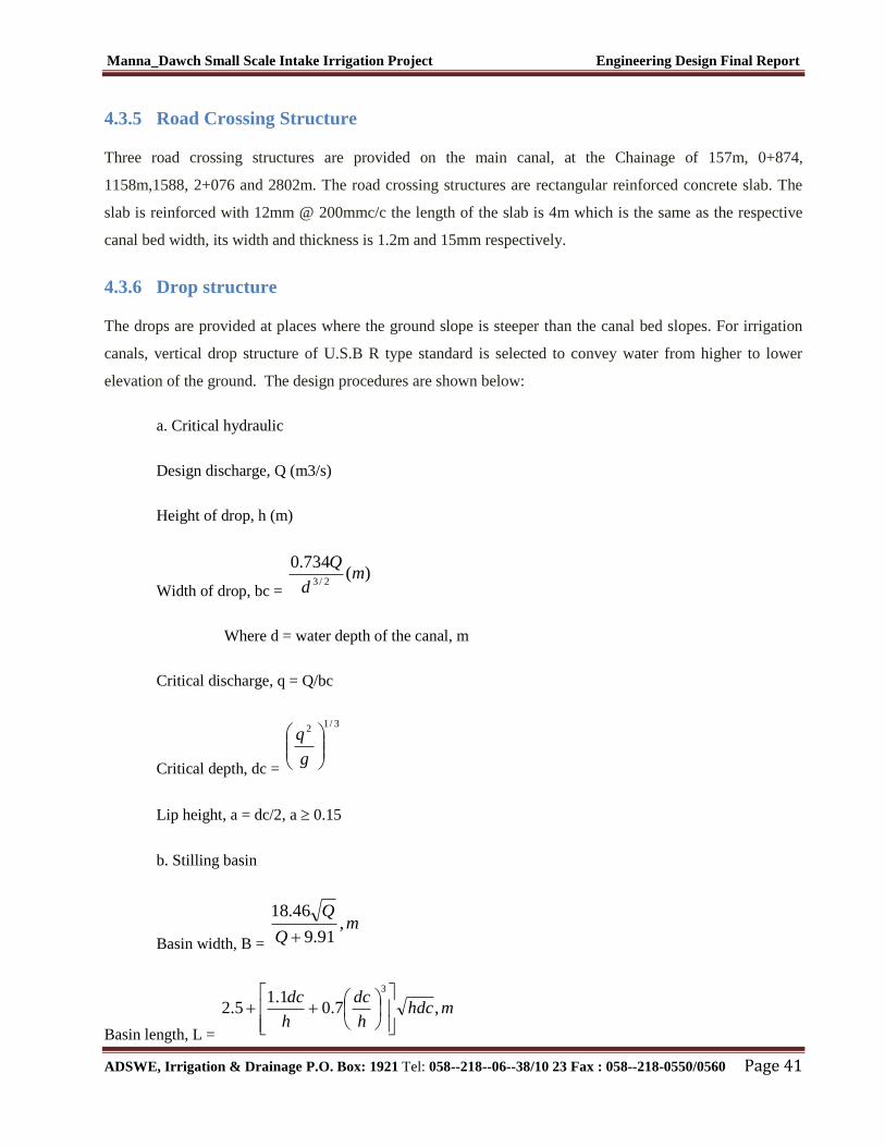
Manna_Dawch Small Scale Intake Irrigation Project Engineering Design Final Report
ADSWE, Irrigation & Drainage P.O. Box: 1921 Tel: 058--218--06--38/10 23 Fax : 058--218-0550/0560 Page 41
4.3.5 Road Crossing Structure
Three road crossing structures are provided on the main canal, at the Chainage of 157m, 0+874,
1158m,1588, 2+076 and 2802m. The road crossing structures are rectangular reinforced concrete slab. The
slab is reinforced with 12mm @ 200mmc/c the length of the slab is 4m which is the same as the respective
canal bed width, its width and thickness is 1.2m and 15mm respectively.
4.3.6 Drop structure
The drops are provided at places where the ground slope is steeper than the canal bed slopes. For irrigation
canals, vertical drop structure of U.S.B R type standard is selected to convey water from higher to lower
elevation of the ground. The design procedures are shown below:
a. Critical hydraulic
Design discharge, Q (m3/s)
Height of drop, h (m)
Width of drop, bc = )(
734.02/3
md
Q
Where d = water depth of the canal, m
Critical discharge, q = Q/bc
Critical depth, dc =
3/12
g
q
Lip height, a = dc/2, a 0.15
b. Stilling basin
Basin width, B =
mQ
Q,
91.9
46.18
Basin length, L =
mhdch
dc
h
dc,7.0
1.15.2
3

Manna_Dawch Small Scale Intake Irrigation Project Engineering Design Final Report
ADSWE, Irrigation & Drainage P.O. Box: 1921 Tel: 058--218--06--38/10 23 Fax : 058--218-0550/0560 Page 42
The standard drawing for all the drops to be constructed is found in the irrigation infrastructure drawings on
which the above parameters are used to code each of the dimensions of the drops.
All the hydraulic parameters computed using the above procedures with the type of canals are shown
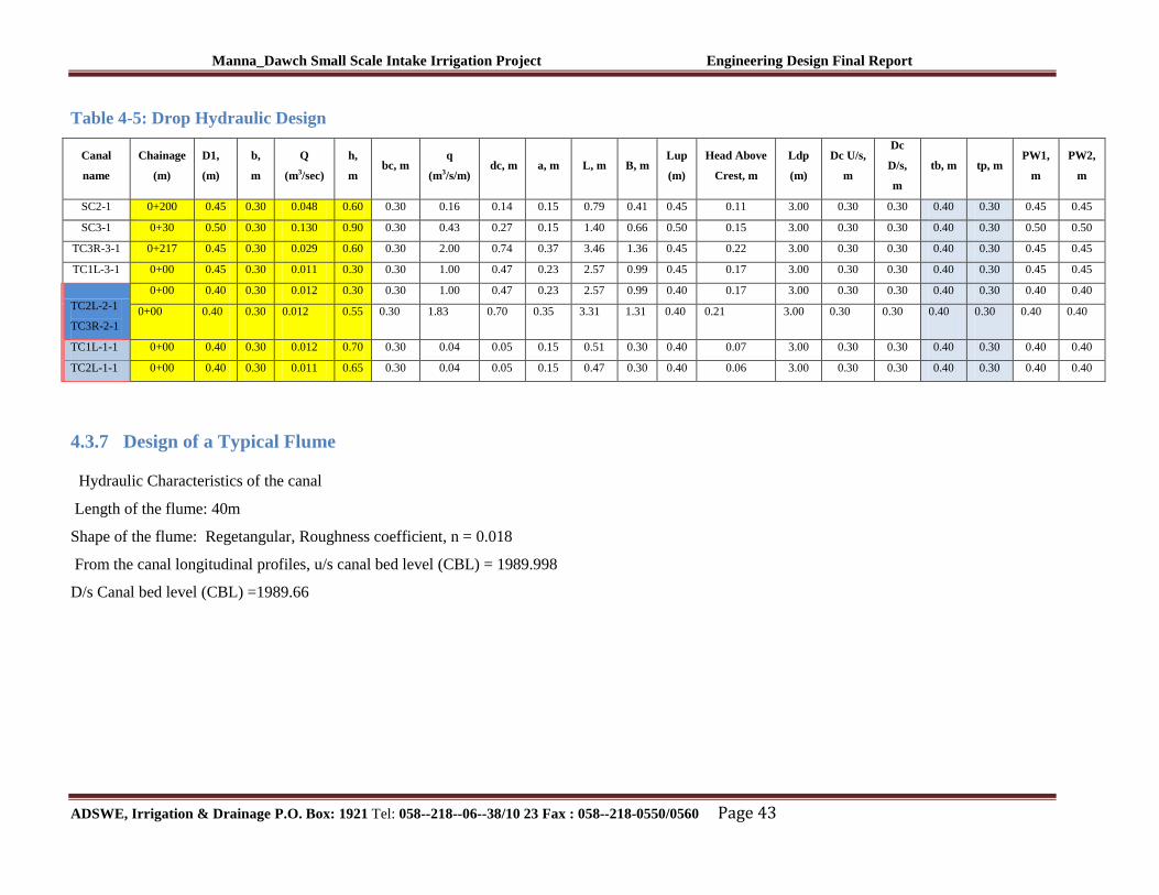
Manna_Dawch Small Scale Intake Irrigation Project Engineering Design Final Report
ADSWE, Irrigation & Drainage P.O. Box: 1921 Tel: 058--218--06--38/10 23 Fax : 058--218-0550/0560 Page 43
Table 4-5: Drop Hydraulic Design
Canal
name
Chainage
(m)
D1,
(m)
b,
m
Q
(m3/sec)
h,
m bc, m
q
(m3/s/m) dc, m a, m L, m B, m
Lup
(m)
Head Above
Crest, m
Ldp
(m)
Dc U/s,
m
Dc
D/s,
m
tb, m tp, m PW1,
m
PW2,
m
SC2-1 0+200 0.45 0.30 0.048 0.60 0.30 0.16 0.14 0.15 0.79 0.41 0.45 0.11 3.00 0.30 0.30 0.40 0.30 0.45 0.45
SC3-1 0+30 0.50 0.30 0.130 0.90 0.30 0.43 0.27 0.15 1.40 0.66 0.50 0.15 3.00 0.30 0.30 0.40 0.30 0.50 0.50
TC3R-3-1 0+217 0.45 0.30 0.029 0.60 0.30 2.00 0.74 0.37 3.46 1.36 0.45 0.22 3.00 0.30 0.30 0.40 0.30 0.45 0.45
TC1L-3-1 0+00 0.45 0.30 0.011 0.30 0.30 1.00 0.47 0.23 2.57 0.99 0.45 0.17 3.00 0.30 0.30 0.40 0.30 0.45 0.45
TC2L-2-1
TC3R-2-1
0+00 0.40 0.30 0.012 0.30 0.30 1.00 0.47 0.23 2.57 0.99 0.40 0.17 3.00 0.30 0.30 0.40 0.30 0.40 0.40
0+00 0.40 0.30 0.012 0.55 0.30 1.83 0.70 0.35 3.31 1.31 0.40 0.21 3.00 0.30 0.30 0.40 0.30 0.40 0.40
TC1L-1-1 0+00 0.40 0.30 0.012 0.70 0.30 0.04 0.05 0.15 0.51 0.30 0.40 0.07 3.00 0.30 0.30 0.40 0.30 0.40 0.40
TC2L-1-1 0+00 0.40 0.30 0.011 0.65 0.30 0.04 0.05 0.15 0.47 0.30 0.40 0.06 3.00 0.30 0.30 0.40 0.30 0.40 0.40
4.3.7 Design of a Typical Flume
Hydraulic Characteristics of the canal
Length of the flume: 40m
Shape of the flume: Regetangular, Roughness coefficient, n = 0.018
From the canal longitudinal profiles, u/s canal bed level (CBL) = 1989.998
D/s Canal bed level (CBL) =1989.66
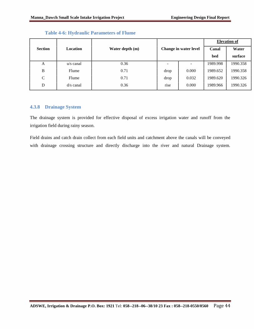
Manna_Dawch Small Scale Intake Irrigation Project Engineering Design Final Report
ADSWE, Irrigation & Drainage P.O. Box: 1921 Tel: 058--218--06--38/10 23 Fax : 058--218-0550/0560 Page 44
Table 4-6: Hydraulic Parameters of Flume
Section Location Water depth (m) Change in water level
Elevation of
Canal
bed
Water
surface
A u/s canal 0.36 - - 1989.998 1990.358
B Flume 0.71 drop 0.000 1989.652 1990.358
C Flume 0.71 drop 0.032 1989.620 1990.326
D d/s canal 0.36 rise 0.000 1989.966 1990.326
4.3.8 Drainage System
The drainage system is provided for effective disposal of excess irrigation water and runoff from the
irrigation field during rainy season.
Field drains and catch drain collect from each field units and catchment above the canals will be conveyed
with drainage crossing structure and directly discharge into the river and natural Drainage system.
Manna_Dawch Small Scale Intake Irrigation Project Engineering Design Final Report
ADSWE, Irrigation & Drainage P.O. Box: 1921 Tel: 058--218--06--38/10 23 Fax : 058--218-0550/0560 Page 45
5 SOURCES OF CONSTRUCTION MATERIALS
During site investigation, natural construction materials required for the construction of the various proposed
engineering structures at the headwork and within the farmland have been assessed, and possible quarry sites
and borrow areas have been identified within the visited of the study area as close to the project site as
possible. In addition to identifying the quality, quantity and accessibility conditions of the construction
materials, ownerships of each proposed production sites have also been studied and described in this report,
on separate sub-sections below. The materials needed for the construction of the structures include rock for
masonry stones, aggregates (both coarse and fine), and water.
5.1 Rock for Masonry and Crushed Coarse Aggregate
During site investigation rocks required for masonry works were identified Masonry stones are highly
required during construction of the project for headwork structure, main canal route structure, cross drainage
structure, and for many other purposes. The aggregates are another required construction material found
during in the construction of the project. The aggregates required for constructions of the project in concrete
work are fine aggregate and coarse aggregate that is sands and crushed stones respectively. Rocks use as
masonry works incorporated in the engineering design and found near the command area at location of
383910E, 1355479N and at elevation of 2014m above sea level near mountain ridges (BOSSENA mender).
In the past time the contractors used this rock for construction of the weir and river bed is additional
construction source, but the rocks occurred as boulders and cobble size. The rock type that exists in the
production quarry site is fine grained volcanic rock within higher quality and the abundance is more than
required amount for both masonry and coarse aggregate and which has 2km distance from headwork site.
The productive quarry sites have no ownerships and accessible in dry season and also which is out of
farmland area.
5.2 Fine Aggregates
Borrow areas for fine aggregate or natural sand have been assessed starting from the project stream itself.
Natural deposits of such materials are during construction process, natural fine aggregate is required for
concrete works and accessing this material in the surrounding area is another issue in the study. Natural
deposits of these materials are found within the beds of MENNA DAWOCH stream itself and the quantity of
sand is more than required amount. The sand deposits are higher in both the upstream and downstream
direction from headwork site and this natural deposit is used by local people for construction purpose in the
surrounding. But the sand source until this study is not used by local contractors due to accessibility problem
Manna_Dawch Small Scale Intake Irrigation Project Engineering Design Final Report
ADSWE, Irrigation & Drainage P.O. Box: 1921 Tel: 058--218--06--38/10 23 Fax : 058--218-0550/0560 Page 46
of the area. Both visual investigation and laboratory testing of the sand deposits that are found in the
proposed area have been done. The secondary source also found nearby stream called Menna (megenagna)
River and natural deposit of this sand is used by local contractors and also far from project area by 22km
distance towards word town called Arbaya. For secondary sand source area also visual investigation and
laboratory test have been done
The laboratory tests of the sand deposits that are found in the Menna_Dawch and Menna River have been
done. To characterize the gradation of the deposit, a sample has been taken for laboratory testing (especially
for gradation test) the sand deposit from Menna_Dawch River itself has the following gradation:
Gravel (>4.75) = 37.15 %
Coarse Sand (4.75-0.425mm) = 40.25%
Fine Sand (0.425-0.075mm) =16.67%
Silt and Clay (<0.075mm) =5.93%
And the secondary sand source (Menna river locally megenagna river) laboratory result also has the
following gradation:
Gravel (>4.75mm) =26.90%
Coarse sand (4.75-0.425mm) =31.11%
Fine sand (0.425-0.075mm) = 38.01 %
Silt and Clay (<0.075mm) =3.99%
From observation the percentage of fines (Silt and clay) and gravel is higher, because the sample is taken by
local contractors repeatedly so that the sand deposit should be washed before using for construction to
remove fines and in addition, the amount of oversize grains (gravels) are also considerable and sieving with
sieve opening of about 4.75 to 5mm is required.
5.3 Water
Water for construction purposes can be found from the project stream Menna River itself. The stream is
perennial throughout the year that there is some amount of flow along its course. During this field time the
stream flow was more than 280L/second.
Manna_Dawch Small Scale Intake Irrigation Project Engineering Design Final Report
ADSWE, Irrigation & Drainage P.O. Box: 1921 Tel: 058--218--06--38/10 23 Fax : 058--218-0550/0560 Page 47
6 OPERATION AND MAINTENANCE
6.1 General
The main objective of the operation and maintenance aspect of an irrigation scheme is to facilitate
the timely delivery of the required irrigation water to farms and to keep the irrigation system in an
optimum operating condition. This section therefore, discusses the main functions of the subject
matter under consideration for the scheme.
6.2 Operation of the Head Works
Operation at the intake mainly focuses on the diversion of a controlled flow of river water, timely
cleaning of floating debris in front of intake and removal of sediment deposits in front of the intake.
6.3 Irrigation System Operation
The operation of the irrigation system depends mainly on the method of water delivery at farm level.
Surface irrigation method is the recommended type of water distribution and application method for
Menna_Dawch intake irrigation scheme.
The farmers would organize themselves and form groups in order to handle the water Management. Since
flow is low Rotational water distribution would be applied within the group. The rotational distribution is
then to distribute water by turn to the whole scheme according to the timely need of crop water requirement.
For better and efficient water Management, crop diversification should be avoided within a group. This
would reduce the complexity of water distribution system of the scheme during one irrigation season. At
farmers’ level of operation, a constant flow and variable irrigation time is advisable.
The operation of the irrigation system is continuous for 20 hours per day in main, secondary and tertiary
canals whereas field canals within a tertiary block are operating in rotational system with each other for
irrigation hours proportional to their size. Since the tertiary canal discharges are within the Manageable
range and the irrigation canal structures are accordingly designed for simple operation, the farmers can open
and close easily whenever they required.
6.4 Maintenance Requirement
The canal system of the project is earthen canal except main canal and secondary canal, which is susceptible
to siltation, erosion, growth of weeds and or breaching problems. Though the canal sections are designed for
Manna_Dawch Small Scale Intake Irrigation Project Engineering Design Final Report
ADSWE, Irrigation & Drainage P.O. Box: 1921 Tel: 058--218--06--38/10 23 Fax : 058--218-0550/0560 Page 48
non- silting and non-scouring conditions, the above mentioned problems are unavoidable and hence
periodical and yearly inspection and maintenance of canals and structures are obligatory in order to fulfill the
design objective of the project area.
The maintenance tasks are categorized into two types: - routine activities, and repairs. The routine
maintenance activities that are carried out periodically include:-
Regular cleaning of sediments and weeds from canals and drains;
Inspection and lubrication of gates; and
Maintenance of cracked lined canals, regulating and control structures.
Repair works include task carried out more frequently and quickly, and include those tasks that are generally
unpredictable. They also include emergency works. The activities included in this category are:-
Repairing overtopped or breached canals, drains, and flood protection dykes;
Repairing jammed gates;
Filling holes made by wild animals; and
Reduced free board due to walking over by people and livestock.
Regular inspection of the irrigation facilities should be carried out as part of the maintenance activities.
These tasks could be carried out immediately after the end of the main rains in September and during the
rainy season. This could concentrate on the interceptor drains and the flood protection dykes, the main
canal and the field drains. The inspection of the other works like the tertiary canals, field drains, and the
water control and regulating structures could be carried out as part of routine operation activities.
Beneficiaries of the project need to have operation and maintenance budget, For O&M cost incurring
entity area:
Purchase sing of gate lubricate (grease)
Replacing and maintenance of Stolen and damaged gates
Repair Damages on the cross drainage structures.
The expense for O&M should be collected from the beneficiaries. Of course, much of the task is done by the
labor and skill of the community. For cost incurring activities beneficiaries have to collect money based on
the proportion of the command area they owned.

Manna_Dawch Small Scale Intake Irrigation Project Engineering Design Final Report
ADSWE, Irrigation & Drainage P.O. Box: 1921 Tel: 058--218--06--38/10 23 Fax : 058--218-0550/0560 Page 49
7 CONCLUSION AND RECOMMENDATION
The infrastructure of this project area is designed to irrigate about 180 ha of land by taking its supply
from the Menna_Dawch intake irrigation project. The maximum duty of the command area for 1.22
hours per day irrigation with overall project efficiency of46%. The method of irrigation of the
project area is furrow surface irrigation in which the main and secondary canals are working
continuously whereas the field canals within a tertiary block are working rotational system.
As the dominant soil type is black cotton, silt clay and clay soil, the main canal system is designed
both earthen and masonry
Secondary canals, one, two and three are earthen. But, secondary canal four is lined.
The design of the canal dimensions of the irrigation canal is done by applying the manning’s uniform
flow equation. The variable of the hydraulic parameters are calculated using iteration or flow master
program.
The following recommendations are drown:
1. For better performance and long service year of the project regular inspection and maintenance
is highly required.
2. Farmers training, how to operate and maintain the project structures as a whole and available
and water resources has a paramount important.
3. The irrigation hours per day and per week should be flexible based on base flow amount of each
week or month.
4. Close supervision of the construction should be made to modify (if need be) each Components
of irrigation system based on specific site conditions.

Manna_Dawch Small Scale Intake Irrigation Project Engineering Design Final Report
ADSWE, Irrigation & Drainage P.O. Box: 1921 Tel: 058--218--06--38/10 23 Fax : 058--218-0550/0560 Page 50
8 REFERENCE
1. FAO (1977) guidelines for predicting crop water requirements. No 24, Rome Italy
2. Applied Hydrology (1988) by Von Tec how David R. Maidment and Larry w.
3. Design of small Canal structures , USBR