mainboard manual - priede.bf.lu.lvpriede.bf.lu.lv/ftp/pub/os/mates_deli/fic/fs39/fs39_a0_eng.pdf1 -...
TRANSCRIPT

FS39
MAINBOARD
MANUAL
DOC No.: M00B02
Rev. : A0
Date : 12, 2000
Part No. : 25-11604-20

i
Table of ContentsTable of Contents
Chapter 1 OverviewPackage Checklist .......................................................................... 1-2
The FS39 Mainboard ................................................................. 1-3Main Features ................................................................................ 1-4ACPI Ready ................................................................................... 1-6FIC Unique Innovation for Users (NOVUS) -Enhanced Mainboard Features and System Support .................... 1-6
Chapter 2 Installation ProceduresQuick Reference (from Page 2-2 to 2-3) .......................................... 2-2
Mainboard Layout .................................................................... 2-21). Clear CMOS, Clear Password ....................................... 2-32). Front Panel Block Cable Connection ............................ 2-33). CPU Fan Installation .................................................... 2-3
1). Set System Jumpers/Switches ................................................... 2-4Clear CMOS: SW1-1 .......................................................... 2-5Clear Password: SW1-2 ..................................................... 2-5
2). Install RAM Modules ............................................................... 2-63). Install the CPU .......................................................................... 2-64). Install Expansion Cards ............................................................. 2-85). Connect Devices ....................................................................... 2-9
Floppy Diskette Drive Connector: FLOPPY ...................... 2-9IDE Device Connectors: PRIMARY, SECONDARY ........... 2-10Infrared Connector: IR ....................................................... 2-10ATX Power Connector: ATX_PWR .................................. 2-11CPU Fan Connector: CPU_FAN ........................................ 2-11System Case Fan Connector: SYS_FAN ........................... 2-12CD Audio-In Connector: CD_IN ....................................... 2-12Wake-On-LAN Connector: WOL ...................................... 2-13Front Panel Block Connector: F_PNL ............................... 2-13PS/2 Keyboard and Mouse Connector: KB, MS ............... 2-15Universal Serial Bus Connectors: Rear USBs, Front USBs 2-15Serial Port Connectors: COM1, COM2 .............................. 2-16Printer Connector: LPT ...................................................... 2-16

ii
FS39 Mainboard Manual
Audio I/O Jacks: LINE_OUT, LINE_IN, MIC_IN,FNT_AUDIO ..................................................................... 2-17Game/MIDI Connector: GAME ......................................... 2-17
Chapter 3 BIOS SetupCMOS Setup Utility ....................................................................... 3-1Standard CMOS Setup ................................................................... 3-2Advanced BIOS Features .............................................................. 3-4Advanced Chipset Features .......................................................... 3-8Integrated Peripherals .................................................................... 3-10Power Management Setup ............................................................. 3-16PnP/PCI Configurations ................................................................. 3-20PC Health Status ............................................................................ 3-21Frequency/Voltage Control ............................................................ 3-22Load Fail-Safe Defaults .................................................................. 3-23Load Optimized Defaults ................................................................ 3-24Supervisor/User Password ............................................................ 3-24Save and Exit Setup ....................................................................... 3-25Exit without Saving ........................................................................ 3-26
AppendixHardware Monitor Software Adjustment ....................................... A-1

1 - 1
Overview
Overview
Chapter 1
The new Micro ATX, Socket 370 1stMainboard FS39 supports a full range ofthe latest generation Intel® and Cyrix processors. Intel�s new Celeron � andlightening fast Coppermine processors of up to 1GHz* and up are supportedwith Front Side Bus speeds of 66/100/133 MHz. Built using the leading edge0.18 micron technology the Intel FCPGA Pentium®III processors provide asignificant performance scaling boost over previous Pentium®III processors.(*: not yet test)
The Intel 815EP accelerated Hub architecture provides onboard audio pro-vided by the state of the art embedded codec. Support for the Ultra DMA/100protocol and its high-speed interface further ensures that data transfer speedsare improved, especially for long sequential transfers required by audio/visualapplications. With 2 DIMM sockets, the board supports up to total 512 MB byusing 100/133MHz 3.3V SDRAM.
The 1stMainboard FS39 comes with a versatile range of I/O features such as 2serial ports, 1 parallel port, 1 PS/2 mouse and keyboard connector, 2 USBconnectors, 1 front USB pin header, 1 front audio pin header, 1 media connec-tor (MIDI /game port, Line-in, Line-out and Mic-in). Ample expansion is avail-able through 3 PCI and 1 CNR.
Other key features are Remote On/Off, Auto Power Failure Recovery, Key-board /Mouse Power On, integrated temperature monitoring and system fancontrol. Included also is CD Pro with enhanced drivers and the new CD Pluspackage containing 9 bundled soft-ware solutions including Norton AntiVirus,Ghost, Virtual Drive.

1 - 2
FS39 Mainboard Manual
Package ChecklistIf you discover any item below was damaged or lost, please contact yourvendor.
þ The mainboard þ This user manual
þ One FDD cable þ One HDD cable
þ One ATA/66 cable þ Two software CDs (CD Pro, CD Plus)

1 - 3
Overview
The FS39 Mainboard

1 - 4
FS39 Mainboard Manual
Main Features■ Easy Installation
||BIOS with support for Plug and Play, auto detection of IDE hard drives,||LS-120|drives, IDE ZIP drives, Windows 95, Windows 98, Windows ME,||Windows NT, Windows 2000, |and OS/2.
■ Leading Edge ChipsetIntel 815EP provides integrated DRAM controllers with new DynamicPower Management Architecture (DPMA), concurrent PCI , and USB.
■ Versatile Main Memory SupportAccepts up to 512MB SDRAM using two DIMMs of 32, 64, 128, 256MBwith support for lightning-fast SDRAM (100/133MHz).
■ CNR, AGP, and PCI Expansion SlotsOne CNR, one AGP Bus expansion slot, and three PCI Bus expansionslots provided the room to install a full range of add-on cards.
■ Onboard IrDA ConnectorAn IrDA connector for wireless infrared connections is available.
■ Flexible Processor SupportOnboard CPU socket supports:Intel® Celeron FC-PGA 533/566/600/633*/667*/700*/733* MHz at 66 MHzFSBIntel® Pentium III FC-PGA 500/550/600/650/700/750/800/850 MHz at100MHz FSBIntel® Pentium III FC-PGA 533/600/667/733/800/866/933* MHz/1* GHz at133MHz FSBCyrix® III 533-600 MHz and beyond* at 100/133 MHz FSB
(*: not yet test)

1 - 5
Overview
■ Integrated Audio SubsystemEmbedded audio features in the ICH2 with an integrated PCI audio con-troller, DOS games compatible engine. The subsystem utilizes line-out,line-in, and MIC mini-jack external jacks, one joystick port with MIDIinterface.
■■■■■ Super Multi Input/Output (I/O) SupportIntegrated Plug and Play multi-I/O chipset features two high-speed UART16550 compatible serial ports, one EPP/ECP capable parallel port, onegame port, and one FDD connector.
■■■■■ Convenient Rear Panel USB Connection SupportTwo USB ports integrated in the rear I/O panel with two USB front panelconnections allow convenient and high-speed Plug and Play connec-tions to the growing number of USB compliant peripheral devices on themarket.
■■■■■ Accelerated Graphics Port (AGP) SlotThe motherboard is installed one 32-bit AGP bus slot with a dedicated66MHz/133MHz path from the graphics card to the system memory offer-ing much greater bandwidth than the 32-bit PCI bus does. AGP enabled3D graphics cards can directly access main memory across this fast pathinstead of using local memory. To make use of the improved AGP perfor-mance, the motherboard should be installed with SDRAM type memoryand the VGA card and drivers should also be fully AGP compliant. UsingMicrosoft�s Windows 98 and Windows 2000 which implement DirectDrawwill allow the system to take full use of AGP�s benefits without the need toinstall additional drivers.
■ Enhanced PCI Bus Master IDE Controller with Ultra DMA 33/66/100SupportIntegrated Enhanced PCI Bus Master IDE controller features two dual-channel connectors that up to four Enhanced IDE devices, including CD-ROM and Tape Backup Drives, as well as Hard Disk Drives supportingthe new Ultra DMA 100 protocol. Standard PIO Mode 3, PIO Mode 4,DMA Mode 2, DMA Mode 4, UltraDMA-100 Mode 5 devices are alsosupported.

1 - 6
FS39 Mainboard Manual
FIC Unique Innovation for Users (NOVUS) -Enhanced Mainboard Features and System Support
■■■■■ LogoGenieA user friendly GUI supporting Windows 95/98 (not Windows 2000/NT/ME), LogoGenie allows you to customize, create or select a Logo whichwill be displayed when the system is booting.
NOTE:1. LogoGenie supports Award BIOS only.2. If you create a Logo file (.bmp) by LogoGenie, the file size must||||be 640 x 464 x 256 colors.
ACPI ReadyThis mainboard fully implements the new ACPI (Advanced Configuration andPower Interface) 1.0B Hardware and BIOS requirement. If you install ACPIaware of operating system, such as Windows 98, you fully utilized the powersaving under ACPI. (Windows ME/2000 Professional supports ACPI func-tions.)
To enable this utility, please proceed as follows:1. Insert CD Pro (4.2 or above). Select LogoGenie from the Menu and
follow the installation instructions.2. After LogoGenie has been installed, go to Windows Start Box.
In Programs Menu, select LogoGenie 2.0, then select LogoGenie.3. Press F1 to read Help file to understand how to use this software if
it is new to you.

1 - 7
Overview
■■■■■ BIOS GuardianBIOS Guardian by default is enabled. It must be disabled in order toreflash BIOS, thus effectively acts as a fire-wall against viruses that canattack the BIOS while the system is running.
WARNING: While excute Step3 below, please do not turn off thesytsem power in order to avoid BIOS damage.
BIOS Guardian can be disabled as follows:1. Go to BIOS Set Up Menu. (Press Del key while booting.)2. Go to Advanced BIOS Features Set Up Submenu.3. Disable BIOS Guardian.4. Save the setting, and restart system.
■■■■■ Easy KeyInstead of completing the multi-layered BIOS setup process these 3 EasyKey functions provide direct access to Sub-Menu�s when completingBIOS settings adjustments.
Easy-Keys are as follows:Ctrl + c: To enter clock settings menu.Ctrl + p: To load Performance Default settings and restart.Ctrl + f: To load Fail-Safe Default settings and restart.
NOTE: However, if it is disabled and while boot the system, thePOST screen will be held and shows you the message to let youknow the current status of BIOS Guardian. To press G key will en-able the BIOS Guardian again; or simply to press the space barwill continue the booting process.

1 - 8
FS39 Mainboard Manual
■■■■■ Overclock PartnerShould the system not start because clock speed settings have beenincreased to a speed incompatible with the system, the Overclock Partnerallows you to reboot at system default settings, protecting hardware fromany damages.
Complete the following steps:1. Turn the system off.2. Restart while holding down the Insert key. It is important that the
Insert key is held down until the default clock speed is shown onthe POST screen.
3. Enter BIOS settings menu, and re-set clock speed desired or default.

2 - 1
Installation ProceduresChapter 2
Installation Procedures
The mainboard has several user-adjustable jumpers on the board that allow you toconfigure your system to suit your requirements. This chapter contains informationon the various jumper settings on your mainboard.
To set up your computer, you must complete the following steps:
■ Step 1 - Set system jumpers/switches
■ Step 2 - Install memory modules
■ Step 3 - Install the Central Processing Unit (CPU)
■ Step 4 - Install expansion cards
■ Step 5 - Connect ribbon cables, cabinet wires, and power supply
■ Step 6 - Set up BIOS software
■ Step 7 - Install supporting software tools
WARNING: Excessive torque may damage the mainboard. Whenusing an electric screwdriver on the mainboard, make sure thatthe torque is set to the allowable range of 5.0 ~ 8.0kg/cm.
Mainboard components contain very delicate Integrated Circuit(IC) chips. To prevent static electricity from harming any of themainboard’s sensitive components, you should follow thefollowing precautions whenever working on the computer:
1. Unplug the computer when working on the inside.2. Hold components by the edges and try not to touch the IC||||chips, leads, or circuitry.3. Wear an anti-static wrist strap which fits around the wrist.4. Place components on a grounded anti-static pad or on the bag that came with the component whenever the components are separated from the system.

2 - 2
FS39 Mainboard Manual
Mainboard Layout
Quick Reference (from Page 2-2 to 2-3)

2 - 3
Installation Procedures
1). Clear CMOS, Clear Password
2). Front Panel Block Cable Connection
3). CPU Fan InstallationThis connector is linked to the CPU fan. When the system is in power saving mode, theCPU fan will turn off; when it reverts back to full on mode, the fan will turn back on.Without sufficient air circulation, the CPU may overheat resulting in damageto both the CPU and the mainboard.Damage may occur to the mainboard and/or the CPU fan if these pins areused incorrectly. These are not jumpers, do not place jumper caps over thesepins.

2 - 4
FS39 Mainboard Manual
1). Set System Jumpers/Switches
Jumpers are used to select the operation modes for your system. Some jump-ers on the board have three metal pins with each pin representing a differentfunction. A �1� is written besides pin 1 on jumpers with three pins. To set ajumper, a black cap containing metal contacts is placed over the jumper pin/saccording to the required configuration. A jumper is said to be shorted whenthe black cap has been placed on one or two of its pins. The types of jumpersused in this manual are shown below:
NOTE: Users are not encouraged to change the jumper settingsnot listed in this manual. Changing the jumper settings improperlymay adversely affect system performance.

2 - 5
Installation Procedures
Clear CMOS: SW1-1The CMOS RAM is powered by the onboard button cell battery. To clear theRTC data: (1) Turn off your computer. (2) Move the CMOS Clear switch SW1-1 to �On� (Enabled). (3) Turn on your computer to display �CMOS checksumerror�. (4) Turn off your computer. (5) Move the CMOS Clear switch SW1-1 to�Off� (Disabled). (6) Turn on your computer. (7) Hold down the Delete keywhen boots. (8) Enter the BIOS Setup to re-enter user preferences.
Clear Password: SW1-2This switch allows you to enable or disable the password configuration. Youmay need to enable this switch by moving it to the �On� (Enabled) position ifyou forget your password. To clear the password setting: (1) Turn off yourcomputer. (2) Move the Clear Password switch SW1-2 to �On� (Enabled). (3)Turn on your computer. (4) Hold down the Delete key during bootup and enterBIOS Setup to re-enter user preferences. (5) Turn off your computer, (6) Movethe Clear Password switch SW1-2 to �Off� (Disabled). (7) Turn on your com-puter for the new settings to take effect.

2 - 6
FS39 Mainboard Manual
Press the clips with both hands to remove the DIMM.
2). Install Memory Modules
1. Locate the DIMM slots on the mainboard.2. Install the DIMM straight down into the DIMM slot using both hands.3. The clip on both ends of the DIMM slot will close up to hold the DIMM
in place when the DIMM reaches the slot�s bottom.

2 - 7
Installation Procedures
3). Install the CPUThe mainboard has built-in Switching Voltage Regulator to support CPU Vcoreautodetection. That is, It has the ability to detect and recognize the CPUvoltage, clock, ratio and enables users to set up the CPU frequency from theBIOS Setup Screen. Users can adjust the frequency through �Frequency /Voltage Control� of the BIOS Setup Screen.
To install the CPU, do the following:
1. Lift the lever on the side of the CPU socket.
2. Handle the chip by its edges and try not to touch any of the pins.
3. Place the CPU in the socket. The chip has two notches to correctly locatethe chip. Align two notches of the processor with the two triangularmarks on the socket. Do not force the chip. The CPU should slide easilyinto the socket.
4. Swing the lever to the down position to lock the CPU in place.
5. Place the cooling fan with heatsink on top of the installed CPU.

2 - 8
FS39 Mainboard Manual
4). Install Expansion Cards
This section describes how to connect an expansion card to one of yoursystem�s expansion slots. Expansion cards are printed circuit boards that,when connected to the mainboard, increase the capabilities of your system.For example, expansion cards can provide video and sound capabilities. Themainboard features one CNR, one AGP, and three PCI bus expansion slots.
CAUTION: Make sure to unplug the power supply when adding orremoving expansion cards or other system components. Failure todo so may cause severe damage to both the mainboard andexpansioncards.Always observe static electricity precautions.Please read “Handling Precautions” at the start of this manual.
To install an expansion card, follow the steps below:
1. Remove the computer chassis cover and select an empty expansionslot.
2. Remove the corresponding slot cover from the computer chassis.Unscrew the mounting screw that secures the slot cover and pullthe slot cover out from the computer chassis. Keep the slot covermounting screw nearby.

2 - 9
Installation Procedures
5. Secure the board with the mounting screw removed in Step 2. Makesure that the card has been placed evenly and completely into theexpansion slot.
6. Replace the computer system�s cover.7. Setup the BIOS if necessary.8. Install the necessary software drivers for the expansion card.
3. Holding the edge of the peripheral card, carefully align the edgeconnector with the expansion slot.
4. Push the card firmly into the slot. Push down on one end of theexpansion card, then the other. Use this �rocking� motion until theadd�on card is firmly seated inside the expansion slot.
5). Connect Devices
Floppy Diskette Drive Connector: FLOPPYThis connector provides the connection with your floppy disk drive.The red stripe of the ribbon cable must be the same side with the Pin 1.

2 - 10
FS39 Mainboard Manual
IDE Device Connectors: PRIMARY, SECONDARYThese two connectors are used for your IDE hard disk drives, CD drives, LS-120|drives, or IDE ZIP drives. The red stripe of the ribbon cable must be thesame side with the Pin 1.
Infrared Connector: IRThis 5-pin connector is used to link with your IR device to allow transmissionof data to another system that also supports the IR feature. This modulemounts to a small opening on system cases that support it.

2 - 11
Installation Procedures
ATX Power Connector: ATX_PWRThis 20-pin male block connector is connected to the ATX power supply. Theplug from the power supply will only insert in one orientation because of thedifferent hole sizes. Find the proper orientation and push down firmly makingsure that the pins are aligned.
CPU Fan Connector: CPU_FANThis connector is linked to the CPU fan. When the system is in S3 suspendmode, the CPU fan will turn off; when it reverts back to full�on mode, the fanwill turn back on. Please refer to the CPU fan installation manual for moreinformation.

2 - 12
FS39 Mainboard Manual
CD Audio-In Connector: CD_INThe CD_IN connector is used for CD-ROM drive audio input.
System Case Fan Connector: SYS_FANThe 3-pin connector allows you to link with the cooling fan on the system caseto lower the system temperature.

2 - 13
Installation Procedures
Wake-On-Lan Connector: WOLThis 3-pin connector allows the remove servers to manage the system thatinstalled this mainboard via your network adapter which also supports WOL.When you install such a LAN card, please read its installation guide for moreinformation.
Front Panel Block Connector: F_PNLThis block connector includes the connectors for linking with IDE LED, powerLED, safe mode button, power button, message LED, reset button and speakeron the front panel of the system case. Please identify polarities of plug wiresfor the case speaker and LEDs. Please ask vendor about this information whenyou buy them and install the system by yourself. The plug wires polarities ofthese buttons will not affect the function.

2 - 14
FS39 Mainboard Manual
Message LED is connected with the message LED. When the system is run-ning normally, the indicator is off. It is controlled by the operating system orapplication software.
Reset Button is connected to the reset button. Push this switch to reboot thesystem instead of turning the power button off and on.
Power Button is connected with power button. Push this switch allows thesystem to be turned on and off rather than using the power supply button.
Power LED is connected with the system power indicator to indicate whetherthe system is on/off. It will blink when the system enters suspend mode.
Speaker is connected with the case speaker.
IDE LED is connected to the IDE device indicator. This LED will blink whenthe hard disk drives are activated.
Safe Mode is a two-pin jumper. To short it will boot up you system by forcingthe CPU/Bus ratio be x 2. It could be used to solved the problem that thesystem booting failure caused by the ratio unappropriately set. After selectthe new ideal ratio, please open it and reboot the system.

2 - 15
Installation Procedures
PS/2 Keyboard and Mouse Connector: KB, MSThese two 6-pin female (PS/2 keyboard is purple color and PS/2 mouse isgreen color) connectors are used for your PS/2 keyboard and PS/2 mouse.
Universal Serial Bus Connectors: Rear USBs, Front USBsThese two black connectors integrated on the edge of the board are used forlinking with USB peripheral devices. This board also provides a connectorUSB2 for linking with the two USB sockets on the front panel of some systemcases. Please note your operating system must support USB features, such asMS Windows 98, MS Windows 95 OSR2.5 with USB Supplement.
The figure below is the pin assignmentof the USB2 connector for two front panelUSB connections.

2 - 16
FS39 Mainboard Manual
Printer Connector: LPTThis 25-pin D-Sub female burgundy-colored connector is attached to yourprinter.
Serial Port Connectors: COM1, COM2COM1/2 (9-pin D-sub male connector with teal color) allow you to connectwith your devices that use serial ports, such as a serial mouse or an externalmodem.
2 - 17
Installation Procedures
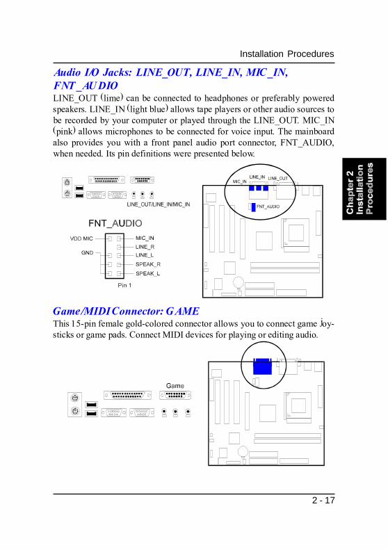
Game/MIDI Connector: GAMEThis 15-pin female gold-colored connector allows you to connect game joy-sticks or game pads. Connect MIDI devices for playing or editing audio.
Audio I/O Jacks: LINE_OUT, LINE_IN, MIC_IN,FNT_AUDIOLINE_OUT (lime) can be connected to headphones or preferably poweredspeakers. LINE_IN (light blue) allows tape players or other audio sources tobe recorded by your computer or played through the LINE_OUT. MIC_IN(pink) allows microphones to be connected for voice input. The mainboardalso provides you with a front panel audio port connector, FNT_AUDIO,when needed. Its pin definitions were presented below.

2 - 18
FS39 Mainboard Manual
This Page Left Blank for Note

3 - 1
BIOS SetupChapter 3
BIOS Setup
A Setup program, built into the system BIOS, is stored in the CMOS. ThisSetup utility program allows updates to the mainboard configuration settings.It is executed when the user changes system configuration; user changessystem backup battery; or the system detects a configuration error and asksthe user to run the Setup program. Use the arrow keys to select and pressEnter to run the selected program.
The mainboard comes with the chip that Award BIOS that contains the ROMSetup information of your system. (This chip serves as an interface betweenthe processor and the rest of the mainboard�s components.) This sectionexplains the information contained in the Setup program and tells you how tomodify the settings according to your system configuration.
CMOS Setup Utility

3 - 2
FS39 Mainboard Manual
Standard CMOS Setup
The Standard CMOS Setup screen is displayed above. Each item may haveone or more option settings. The system BIOS automatically detects memorysize, thus no changes are necessary. Use the arrow keys to highlight the itemand then use PgUp or PgDn keys to select the value you want in each item.
DateTo set the date, highlight the Date field and then press Page Up/PageDown or +/- keys to set the current date. Follow the month, day and yearformat.
TimeTo set the time, highlight the Time field and then press Page Up/Page Downor +/- keys to set the current time. Follow the hour, minute, and secondformat.

3 - 3
BIOS Setup
Hard DisksThis field records the specifications for all non-SCSI hard drives installedin the system. The onboard PCI IDE connectors provide Primary and Sec-ondary channels for connecting up to four IDE hard disks or other IDEdevices. Each channel can support up to two hard disks, the first of whichis the Master and the second is the Slave.
Hard Disk ConfigurationsCapacity: The hard disk size. The unit is Bytes.Cylinder: The cylinder number of the hard disk.Head: The read/write head number of hard disk.Precomp: The cylinder number at which the disk drive
changes the write current.Landing Zone: The cylinder number that the disk drive heads
(read/write) are seated when the disk drive isparked.
Sector: The sector number of each track defined on thehard disk.
Drive A / Drive BThis field records the types of floppy drives installed in the system. Toenter the configuration value for a particular drive, highlight its corre-sponding field and then select the drive type using the left- or right-arrowkey.
VideoSet this field to the type of video display card installed in the system.
Halt OnThis field determines which types of errors will cause the system to halt.
3 - 4
FS39 Mainboard Manual
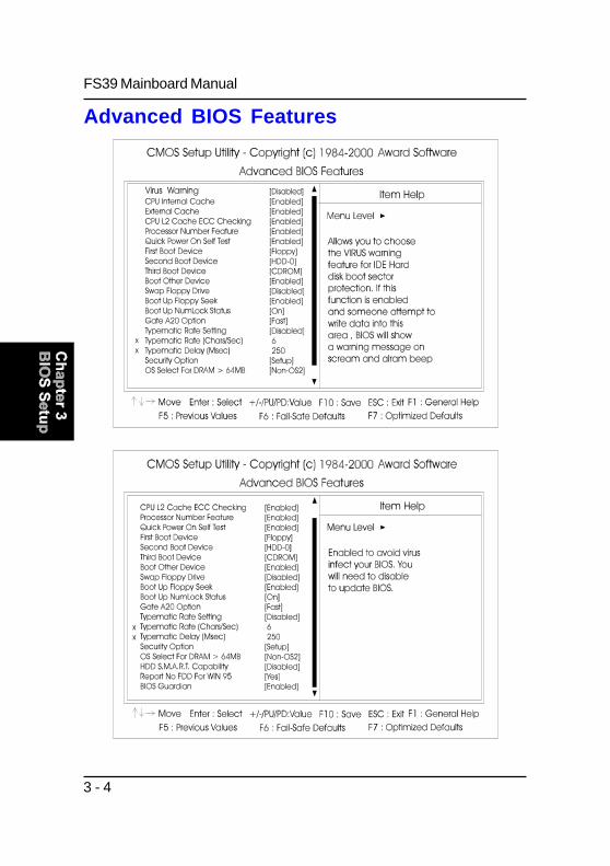
Advanced BIOS Features

3 - 5
BIOS Setup
Virus WarningThis feature allows users to enable the computer virus warning for IDEhard disk boot sector protection. If enabled, BIOS will show a warningmessage and alrm will beep whenever someone write data into this area.The options are: Enabled, Disabled.
CPU Internal CacheWhen enabled, improves the system performance. Disable this item whentesting or trouble-shooting. The options are: Enabled, Disabled.
External CacheWhen enabled, supports an optional cache SRAM. This feature allowsyou to disable the cache function when the system performance is un-stable to run some software. The options are: Enabled, Disabled.
CPU L2 Cache ECC CheckingWhen enabled, it activates the CPU L2 cache check and error correction.The options are: Enabled, Disabled.
Processor Number FeatureIf a Pentium III processor is installed on this mainboard, the system BIOSwill allow other utilities to access the Intel Pentium III serial number whilethis feature set at Enabled. The options are: Enabled, Disabled.
Quick Power On Self TestWhen enabled, allows the BIOS to bypass the extensive memory test.The options are: Enabled, Disabled.
First Boot DeviceThis feature allows user to select the boot device priority. The options are:Floppy, LS120, HDD-0, SCSI, CDROM, HDD-1, HDD-2, HDD-3, ZIP100,USB-FDD, USB-ZIP, USB-CDROM, USB-HDD, LAN, Disabled.
Second Boot DeviceThis feature allows user to select the boot device priority. The options are:Floppy, LS120, HDD-0, SCSI, CDROM, HDD-1, HDD-2, HDD-3, ZIP100,USB-FDD, USB-ZIP, USB-CDROM, USB-HDD, LAN, Disabled.

3 - 6
FS39 Mainboard Manual
Boot Other DeviceThis feature allows user to select the boot device priority.The options are: Enabled, Disabled.
Swap Floppy DriveAllows you to switch the order in which the operating system accessesthe floppy drives during boot up.The options are: Enabled, Disabled.
Boot Up Floppy SeekWhen enabled, assigns the BIOS to perform floppy diskette drive tests byissuing the time-consuming seek commands.The options are: Enabled, Disabled.
Boot Up Numlock StatusWhen set to On, allows the BIOS to automatically enable the Num LockFunction when the system boots up. The options are: On, Off.
Gate A20 OptionWhen set at Fast, allows a faster access response under Protected mode.The options are: Fast, Normal.
Typematic Rate SettingThe term typematic means that when a keyboard key is held down, thecharacter is repeatedly entered until the key is released.The options are: Disabled, Enabled.
Typematic Rate (Chars/Sec)This feature is available only if the above item, Typematic Rate Setting, isset at Enabled. Sets the rate of a character repeat when the key is helddown. The options are: 6, 8, 10, 12, 15, 20, 24, 30.
Third Boot DeviceThis feature allows user to select the boot device priority. The options are:Floppy, LS120, HDD-0, SCSI, CDROM, HDD-1, HDD-2, HDD-3, ZIP100,USB-FDD, USB-ZIP, USB-CDROM, USB-HDD, LAN, Disabled.

3 - 7
BIOS Setup
Report No FDD For WIN 95When the field under the Standard CMOS Setup Menu for Drive A andDrive B is set at None, users must set this field is set at Yes for it to functionproperly. Otherwise, set at No, even if field for Drive A and Drive B is setat None, system will still detect and recognize of a floppy drive(s).The options are: Yes, No.
BIOS GuardianIt allows the system to prevent computer viruses. Users will need to dis-able it to update BIOS. The options are: Enabled, Disabled.
NOTE: Please disable this BIOS feature about BIOS Guardianbefore you start to reflash BIOS.
Security OptionAllows you to set the security level of the system.The options are: Setup, System.
OS Select For DRAM > 64MBIf your operating system (OS) is OS/2, select the option OS2. Otherwise,stay with the default setting Non-OS2.The options are: Non-OS2, OS2.
HDD S.M.A.R.T. CapabilityS.M.A.R.T. stands for Self-Monitoring and Analysis Reporting Technol-ogy which allows your hard disk drive to report any read/write errors andissues a warning with LDCM installed.The options are: Disabled, Enabled.
Typematic Delay (Msec)This feature is available only if the item, Typematic Rate Setting, is set atEnabled. Sets the delay time before a character is repeated.The options are: 250, 500, 750, 1000 millisecond.

3 - 8
FS39 Mainboard Manual
SDRAM CAS Latency TimeThis feature allows user to select the CAS latency time, when any SDRAMDIMM installed. The options are: Auto, 2, 3.
SDRAM Cycle Time Tras/TrcThe feature allows user to set the SCLKs number for an access cycle.The options are: 5/7, 7/9.
SDRAM RAS-to-CAS DelayThe feature allows user to set the delay time that from the SDRAM RAS#active to CAS#. The options are: 3, 2.
SDRAM RAS Precharge TimeThe feature allows user to set the SDRAM RAS# Precharge Time.The options are: 3, 2.
Advanced Chipset Features

3 - 9
BIOS Setup
System BIOS CacheableSetting at Enabled will allow the caching of the BIOS ROM F0000H-FFFFFH,resulting in better system performance. It may cause system error whensome programd try to access the memory area.The options are: Disabled, Enabled.
Video BIOS CacheableSetting at Enabled will allow the caching of the video BIOS ROM at C0000H-C7FFFH, resulting in better video performance. It may cause system errorwhen some programd try to access the memory area.The options are: Disabled, Enabled.
Memory Hole At 15M-16MWhen set at Enabled, the memory hole at 15MB address will be relocatedto the 15M-16MB address range of the ISA or PCI cycle when the CPUaccesses the 15M-16MB address area. When set at Disabled, the memoryhole at 15MB address will be treated as a DRAM cycle when the CPUaccesses the 15M-16MB address area. The options are: Disabled, Enabled.
Delayed TransactionSetting at Eanbled will abort the current PCI master cycle and to accept thenew PCI master request, it reaccepts the original PCI master and returnsthe PCI data phase to the original PCI master. It will enhance the systemperformance. The options are: Disabled, Enabled.
AGP Graphics Aperature SizeIt allows user to select the main memory frame size of AGP use.The options are: 32MB, 64MB.
CPU Latency TimerThis feature sets the CPU latency item for fixing Japanese Win95 problem.The options are: Disabled, Enabled.
System Memory FrequencyIt allows user to select the system memory frequency.The options are: Auto, 100 MHz, 133 MHz.

3 - 10
FS39 Mainboard Manual
Integrated Peripherals

3 - 11
BIOS Setup
On-Chip Primary PCI IDEWhen enabled, it allows you to use the onboard primary PCI IDE. Theoptions are: Enabled, Disabled.
On-Chip Secondary PCI IDEWhen enabled, it allows you to use the onboard secondary PCI IDE. Theoptions are: Enabled, Disabled.
IDE Primary Master PIOAllows an automatic or a manual configuration of the PCI primary IDEhard drive (master) mode. The options are: Auto, Mode 0, Mode 1, Mode2, Mode 3, Mode 4.
IDE Secondary Master PIOAllows an automatic or a manual configuration of the PCI secondary IDEhard drive (master) mode. The options are: Auto, Mode 0, Mode 1, Mode2, Mode 3, Mode 4.
IDE Secondary Slave PIOAllows an automatic or a manual configuration of the PCI secondary IDEhard drive (slave) mode. The options are: Auto, Mode 0, Mode 1, Mode 2,Mode 3, Mode 4.
IDE Primary Master UDMAAllows an automatic configuration of the PCI primary IDE hard drive(master) mode if Ultra DMA is supported both on the motherboard andthe hard disk. The options are: Auto, Disabled.
IDE Primary Slave PIOAllows an automatic or a manual configuration of the PCI primary IDEhard drive (slave) mode. The options are: Auto, Mode 0, Mode 1, Mode 2,Mode 3, Mode 4.
IDE Primary Slave UDMAAllows an automatic configuration of the PCI primary IDE hard drive(slave) mode if Ultra DMA is supported both on the motherboard and thehard disk. The options are: Auto, Disabled.
3 - 12
FS39 Mainboard Manual
USB ControllerDisable this option if you are not using the onboard USB feature.The options are: Disabled, Enabled.
USB Keyboard SupportWhen a USB keyboard is installed, please set at Enabled.The options are: Enabled, Disabled.
Init Display FirstWhen you install an AGP VGA card and a PCI VGA card on the board, thisfeature allows you to select the first initiation of the monitor display fromwhich card. The options are: PCI Slot, AGP.
AC97 AudioThis feature allows users to enable or disable the AC97 audio function.The options are: Auto, Disabled.
AC97 ModemThis feature allows users to enable or disable the AC97 modem function.The options are: Auto, Disabled.
IDE Secondary Master UDMAAllows an automatic configuration of the PCI secondary IDE hard drive(master) mode if Ultra DMA is supported both on the motherboard andthe hard disk. The options are: Auto, Disabled.
IDE Secondary Slave UDMAAllows an automatic configuration of the PCI secondary IDE hard drive(slave) mode if Ultra DMA is supported both on the motherboard and thehard disk. The options are: Auto, Disabled.
IDE HDD Block ModeWhen enabled, the system executes read/write requests to hard disk inblock mode. The options are: Enabled, Disabled.
KBC input clockThis feature allows users to select keyboard controller input clock.The options are: 6 MHz, 8 MHz, 12 MHz, 16 MHz.

3 - 13
BIOS Setup
POWER ON FunctionAllows you to set the method for powering-on the system. The defaultoption of BUTTON ONLY allows system power-on using the standardsystem case mounted ON/OFF switch. The option Password allows youto set up to 5 alphanumeric characters to power-on the system. The optionHot KEY allows you to set which of the 12 keyboard function keys (F1 toF12) in combination with the Ctrl key to power-on the system. The optionMouse Click allows you to use the PS/2 mouse to power-on the system bydouble-clicking on the mouse button. The options are: Password, HotKEY, Mouse Left, Mouse Right, BUTTON ONLY, Any Key, Keyboard 98.
NOTE: When using Password, Hot KEY, or Mouse Click options forthe item POWER ON Function will render the power button on thesystem case ineffective. In case user forgets password or hot keysetting, use the clear password switch or jumper to clear RTCdata. Another method is to unplug system power from the AC poweroutlet and then re-insert the power cord. Previous password andhot key settings will be disabled allowing user to set a new one.
KB Power ON PasswordAllows you set the power on system password.
Hot Key power ONAllows you to set which of the 12 keyboard function keys (F1 to F12) incombination with the Ctrl key will be used to power-on the system. Theoptions are: Ctrl-F1 up to Ctrl-F12.
Onboard FDC Controller
When enabled, the floppy diskette drive (FDD) controller is activated.The options are: Enabled, Disabled.
Onboard Serial Port 1If the serial port 1 uses the onboard I/O controller, you can modify yourserial port parameters. If an I/O card needs to be installed, COM3 andCOM4 may be needed. The options are: Disabled, 3F8/IRQ4, 2F8/IRQ3,3E8/IRQ4, 2E8/IRQ3.

3 - 14
FS39 Mainboard Manual
Onboard Parallel PortAllows you to select from a given set of parameters if the parallel port usesthe onboard I/O controller.The options are: Disabled, 378/IRQ7, 278/IRQ5, 3BC/IRQ7.
UR2 Duplex ModeAllows you to select the IR modes.The options are: Half, Full.
Use IR PinsAllows you to select IR pin mode.The options are: RxD2, TxD2, IR-Rx2Tx2.
Parallel Port ModeAllows you to connect with an advanced printer via the port mode itsupports. The options are: SPP, EPP, ECP, ECP+EPP.
IR Transmission DelayWhen Enabled, the transmission delays 4 characters-time (40 bit-time) ifSIR is changed from RX mode to TX mode. When Disabled, no transmis-sion delay if SIR is changed from RX mode to TX mode.The options are: Enabled, Disabled.
RxD , TxD ActiveThis feature is available only if the item, UART 2 Mode, is set at ASKIR orHPSIR. The feature allows you to select the active signals of the receptionend and the transmission end. This is for technician use only.The options are: Hi, Hi; Hi, Lo; Lo, Hi; Lo, Lo.
Onboard Serial Port 2If the serial port 2 uses the onboard I/O controller, you can modify yourserial port parameters. If an I/O card needs to be installed, COM3 andCOM4 may be needed. The options are: Disabled, 3F8/IRQ4, 2F8/IRQ3,3E8/IRQ4, 2E8/IRQ3.
UART Mode SelectAllows you to select the IR modes if the serial port 2 is used as an IR port.Set at Standard, if you use COM2 as the serial port as the serial port,instead as an IR port. The options are: IrDA, ASKIR, Normal.

3 - 15
BIOS Setup
EPP Mode SelectThis feature allows you to select the EPP type version.The options are: EPP1.9, EPP1.7.
ECP Mode Use DMAThis feature allows you to select Direct Memory Access (DMA) channel ifthe ECP mode selected. The options are: 3, 1.
PWRON After PWR-FailWhen the system is shut down owing to the power failure, the system willnot be back to power on by itself. This feature allows you to set thesystem back to which power status of the system when the system poweris resumed. The options are Off, On, Former-Sts.
Game Port AddressThis feature allows you to select the game port address or disable it.The options are: Disabled, 201, 209.
Midi Port AddressThis feature allows you to select the Midi port address or disable it.The options are: Disabled, 330, 300, 290.
Midi Port IRQIt allows you to select Midi IRQ if Midi is enabled.The options are: 5, 10.

3 - 16
FS39 Mainboard Manual
Power Management Setup

3 - 17
BIOS Setup
Power ManagementThis item allows you to adjust the power management features.
ACPI functionThis item allows you to disable the ACPI function.The options are: Enabled, Disabled.
Select User Define for configuring your own power management features.Min Saving initiates all predefined timers in their minimum values. MaxSaving, on the other hand, initiates maximum values. The options are: UserDefine, Min Saving, Max Saving.
ACPI Suspend TypeThis item allows you to select suspend mode when the system in ACPImode. The options are: S1 (POS), S3 (PTR).
Video Off MethodThe option V/H SYNC+Blank allows the BIOS to blank off screen displayby turning off the V-Sync and H-Sync signals sent from add-on VGA card.DPMS allows the BIOS to blank off screen display by your add-on VGAcard which supports DPMS (Display Power Management Signaling func-tion). Blank Screen allows the BIOS to blank off screen display by turningoff the red-green-blue signals.The options are: Blank Sceen, V/H SYNC+Blank, DPMS.
Video Off In SuspendThe option allows you to select VGA status when the system goes tosuspend mode. The options are: No, Yes.
Suspend TypeThe option allows you to select VGA status when the system goes tosuspend mode. The options are: Stop Grant, PwrOn Suspend.
MODEM Use IRQThis feature allows you to select the IRQ# to meet your modem�s IRQ#.The options are: NA, 3, 4, 5, 7, 9, 10, 11.

3 - 18
FS39 Mainboard Manual
Soft-Off by PWR-BTTNThe selection Delay 4 Sec. will allow the system shut down after 4 secondsafter the power button is pressed. The selection Instant-Off will allow thesystem shut down immediately once the power button is pressed.The settings are: Instant-Off, Delay 4 Sec.
Wake Up On LANWhen set at Enabled, an input signal comes from the other client/server onthe LAN awakes the system from a soft off state if connected over LAN.The options are Disabled, Enabled.
Wake-Up by PCI cardWhen set at Enabled, any PCI-PM event awakes the system from a PCI-PM controlled state. The options are Disabled, Enabled.
Power On by RingAn incoming call via modem awakes the system from its soft-off mode.The options are Disabled, Enabled.
HDD Power DownThe option lets the BIOS turn the HDD motor off when system is in Sus-pend mode. Selecting 1 Min..15 Min allows you define the HDD idle timebefore the HDD enters the Power Saving Mode.The options 1 Min..15 Min will not work concurrently. When HDD is in thePower Saving Mode, any access to the HDD will wake the HDD up.The options are: Disabled, 1 Min..15 Min.
CPU Thermal-ThrottlingWhen thermal override condition occur, this item allows users to deter-mine the duty cycle of the throttling.The options are: 12.5%, 25.0%, 37.5%, 50.0%, 62.5%, 75.0%, 87.5%.
USB KB Wake-Up From S3When set at Enabled, it allows USB keyboard to activate the system fromACPI S3 power saving mode. The options are Disabled, Enabled.
Suspend ModeWhen disabled, the system will not enter Suspend mode. The specifiedtime option defines the idle time the system takes before it enters Suspendmode. The options are: Disabled, 1, 2, 4, 8, 12, 20, 30, 40 Min, 1 Hour.

3 - 19
BIOS Setup
Resume by AlarmThis feature allows you to set the when the system being turned on fromthe system power-off status.The options are: Disabled, Enabled.
Date (of Month)This feature allows you to set the day of the alarm starts when the RTCAlarm Resume From Soft Off is set to be Enabled. The options are: 0, 1..31.
Timer (hh:mm:ss)If an ATX power supply is installed and when RTC Alarm Resume is En-abled, this feature allows you to set the time of the alarm starts when theRTC Alarm Resume From Soft Off is set to be Enabled.The options are: 7: 0: 0 (Default). hh (hour) - 0, 1, 2,.., 23; mm (minute) - 0,1, 2,..,59; ss (second) - 0, 1, 2,..,59.
Primary IDE 0When the primary master HDD is working, the system timer will be re-loaded and the system will not be into the suspend mode.The options are: Disabled, Enabled.
Primary IDE 1When the primary slave HDD is working, the system timer will be reloadedand the system will not be into the suspend mode.The options are: Disabled, Enabled.
Secondary IDE 0When the secondary master HDD is working, the system timer will bereloaded and the system will not be into the suspend mode.The options are: Disabled, Enabled.
** Reload Global Timer Events **
Secondary IDE 1When the secondar slave HDD is working, the system timer will be re-loaded and the system will not be into the suspend mode.The options are: Disabled, Enabled.
3 - 20
FS39 Mainboard Manual
FDD, COM, LPT PortWhen FDD, COM, or LPT is working, the system timer will be reloaded andthe system will not be into the suspend mode.The options are: Disabled, Enabled.
PCI PIRQ[A-D]#When the PCI PIRQ[A-D]# has been alerted, the system timer will be re-loaded and the system will not be into the suspend mode.The options are: Disabled, Enabled.
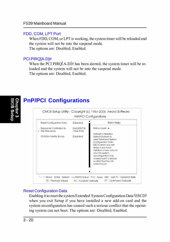
PnP/PCI Configurations
Reset Configuration DataEnabling it to reset the system Extended System Configuration Data (ESCD)when you exit Setup if you have installed a new add-on card and thesystem reconfiguration has caused such a serious conflict that the operat-ing system can not boot. The options are: Disabled, Enabled.

3 - 21
BIOS Setup
PCI/VGA Palette SnoopSet this feature to be enabled if any ISA adapter card installed in thesystem requires the VGA palette snoop function.The options are: Disabled, Enabled.
Resources Controlled ByIf set at Auto, the BIOS arranges all system resources. If there exists con-flict, select Manual. The options are: Auto (ESCD), Manual.If the manual options, after the featrue IRQ Resources being pressed, ofIRQ- Assigned To are: PCI Device, Reserved. When resources were con-trolled manually, assign each system interrupt a type, depending on eachdevice type to use the interrupt.
PC Health Status
CPU Warning TemperatureThis feature allows you to set the temperature to slow down the CPU clockfrequency. The option list presents Disabled and all the temperatures thatsupported by the board.

3 - 22
FS39 Mainboard Manual
Frequency/Voltage Control
Auto Detect DIMM/PCI ClkWhen enabled, BIOS will detect the PCI slot and DIMM slot. If no anydevice in, BIOS will auto disable its clock.The options are: Enabled, Disabled.
Current CPU Temperature / Current CPU FAN Speed / Current CHSSpeed / VCORE / -3.3V / +5V / +12V / -12V / VBAT(V) / 5VSB(V)
These items allow end users and technicians to monitor data provided bythe BIOS on this mainboard. It is not user-configurable.
Shutdown TemperatureThis feature helps to shutdown the system when the system temperatureis as high as the selected temperature to prevent from the overheat prob-lem. The option list presents Disabled and all the temperatures that sup-ported by the board.

3 - 23
BIOS Setup
CPU Host/Sprd Spec/PC133This feature allows you to select the combinations of CPU/PCI clock fre-quency and the Spread Spectrum. The default setting, Default, will detectyour CPU/PCI clock frequency/Spread Spectrum automatically. The rec-ommended CPU clock frequencies are 100 and 133MHz. The other optionsmay effect the system perfomance. If you set a unappropriate option whichleads to a booting problem, keep pressing the Insert key until the displayappears will solve it. The options lists all combinations that provided bythe system BIOS.
CPU Clock RatioThis feature allows you to select the frequency mulitplier for CPU hostclock. The option list offers the ratios from X 3 to X 8.
Load Fail-Safe Defaults
This submenu is selected to diagnose the problem after the computer boots, ifthe computer will not boot. These settings do not give optimal performance.

3 - 24
FS39 Mainboard Manual
Load Optimized Defaults
This submenu is selected for default settings which provide the best systemperformance.
Supervisor/User Password

3 - 25
BIOS Setup
Under the BIOS Feature Setup, if Setup is selected under the Security Optionfield and the Supervisor/User Password is enabled, you will be promptedpassword every time you try to enter the CMOS Setup Utility. If System isselected and the Supervisor/User Password is enabled, you will be requestedto enter the Password every time when you reboot the system or enter theCMOS Setup utility.
To enable the Supervisor/User passwords, select the item from the StandardCMOS Setup. You will be prompted to create your own password. Type yourpassword up to eight characters and press Enter. You will be asked to confirmthe password. Type the password again and press Enter. To disable password,press Enter twice when you are prompted to enter a password. A messageappears, confirming the password is disabled.
Save and Exit Setup
After you have made changes under Setup, press Esc to return to the mainmenu. Move cursor to Save and Exit Setup or press F10 and then press Y tochange the CMOS Setup. If you did not change anything, press Esc again ormove cursor to Exit Without Saving and press Y to retain the Setup settings.The following message will appear at the center of the screen to allow you tosave data to CMOS and exit the setup utility: SAVE to CMOS and EXIT (Y/N)?

3 - 26
FS39 Mainboard Manual
Exit without SavingIf you select this feature, the following message will appear at the center of thescreen to allow you to exit the setup utility without saving CMOS modifica-tions: Quit Without Saving (Y/N)?

A - 1
AddendumAppendix
Hardware Monitor Software Adjust-ment
The software tool Hardware Monitor that in the CD Pro disk provides userswith the warning messages to prevent the computer system from overheatingdamage. The monitor utility for FS39 mainboard does not support the systemtemperature monitoring. The data that appears in the display of System Tem-perature item is false.
Secondly, if a chassis fan is not onboard or it does not own the capability toreport the rotation speed, the software will also give some random data.
To avoid these misleading messages, some settings for the software attributesare necessary.
First of all, (assume it was installed) start Hardware Monitor. The displaybelow will pop up on the screen. Notice that the message in the black circle isgiven randomly.
Select the icon in the white circle. The lower level menu will appear on thescreen. (See the figure on the next page.)

A - 2
FS39 Mainboard Manual
Disable the item SYS temperature.
After the procedures described above, the false message about system tem-perature (and about chassis fan, if no chassis fan or an unqualified chassis fanonboard) will not be given.
NOTE: Chassis FanIf the chassis fan is not installed or does not own the property thatreports its rotation speed to the system, the message about chas-sis fan shown in Hardware Monitor software will also be givenfalsely. Please also turn off the item Chassis Fan in the circle.
Click the button Apply to confirm the settings.

Handling PrecautionsWarning:1. Static electricity may cause damage to the integrated circuits on
the motherboard. Before handling any motherboard outside of itsprotective packaging, ensure that there is no static electric chargein your body.
2. There is a danger of explosion if the battery is incorrectlyreplaced. Replace only with the same or an equivalent typerecommended by the manufacturer.
3. Discard used batteries according to the manufacturer’sinstructions.
4. Never run the processor without the heatsink properly and firmly attached. PERMANENT DAMAGE WILL RESULT!
Observe the following basic precautions when handling the motherboardor other computer components:n Wear a static wrist strap which fits around your wrist and is
connected to a natural earth ground.
n Touch a grounded or anti-static surface or a metal fixture such as awater pipe.
n Avoid contacting the components on add-on cards, motherboards,and modules with the golden fingers connectors plugged into theexpansion slot. It is best to handle system components by theirmonting brackets.
The above methods prevent static build-up and cause it to be dischargedproperly.
TrademarkAll trademarks mentioned in this manual are registered properly ofthe respective owners.
Handling PrecautionsThis manual may not, in whole or in part, be photocopied, reproduced,transcribed, translated, or transmitted in whatever form without thewritten consent of the manufacturer, except for copies retained by thepurchaser for personal archival purposes.
Notice