@main manual.doc f8 - elecraft manual rev f.pdf · the elecraft k2 is a high-performance,...
TRANSCRIPT

+
+
+
++
+
+E L E C R A F T A=BA/B
AGC
NB
PRE/ATT
RATE
MENU
ANT 1/2
21 3
4 5 6
7 98
RIT XIT
0
DISPLAYBAND MODE
FXFIL
KEYER
AF GAIN
BAND -
+
POWER
RF GAIN
NB ANT2 PRE ATT A B RIT XIT
-1 +1
S1
MSG
0
5 9 +20 40
T R A N S C E I V E R
SPLITREV
LOCK
EDIT
RCL
STORE
LEVEL
TUNE
PF1 PF2
RF/ALC
AFILCW RV
REC
VOX
SPOT
K 2
ALCRF 3 5 7 10
OFFON
E L E C R A F T K 2 T R A N S C E I V E R
O W N E R’S M A N U A L

E L E C R A F T
K 2
160-10 MeterS S B/CW
T r a n s c e i v e r
Owner’s ManualRevision F, January 29, 2004
Copyright 2004 Elecraft, LLC
All Rights Reserved
Elecraft • www.elecraft.com P.O. Box 69 • Aptos, CA 95001-0069 (831) 662-8345 • Fax: (831) 662-0830

2 ELECRAFT
Table of Contents1. INTRODUCTION.................................................................................................................................................................................... 3
2. SPECIFICATIONS ................................................................................................................................................................................ 5
3. PREPARATION FOR ASSEMBLY.................................................................................................................................................... 7
4. CONTROL BOARD............................................................................................................................................................................ 13
5. FRONT PANEL BOARD.................................................................................................................................................................... 22
6. RF BOARD.......................................................................................................................................................................................... 33
7. FINAL ASSEMBLY............................................................................................................................................................................. 78
8. OPERATION........................................................................................................................................................................................ 81
9. CIRCUIT DETAILS............................................................................................................................................................................ 106
10. OPTIONS............................................................................................................................................................................................ 113
PARTS LIST.............................................................................................................................................................................APPENDIX A
SCHEMATIC.............................................................................................................................................................................APPENDIX B
BLOCK DIAGRAM..................................................................................................................................................................APPENDIX C
PHOTOGRAPHS.....................................................................................................................................................................APPENDIX D
TROUBLESHOOTING............................................................................................................................................................APPENDIX E
PARTS PLACEMENT DRAWINGS....................................................................................................................................... APPENDIX F
100-WATT STAGE AND RS232 I/O (K2/100) .......................................................APPENDIX G (SUPPLIED WITH KPA100 OPTION)

ELECRAFT 3
1. IntroductionThe Elecraft K2 is a high-performance, synthesized, CW/SSBtransceiver that covers all HF bands. It is a true dual-purposetransceiver, combining the operating features you’d expect in ahome-station rig with the small size and weight of a rugged,go-anywhere portable.
The basic K2 operates on 80-10 meter CW, and provides over 10watts of RF output. If you prefer a full-power station, you cancomplete your K2 as a K2/100 at any time by adding the internal100-watt final stage (KPA100 option). Assembly of the KPA100is covered in Appendix G, a separate manual supplied with theKPA100 kit.
You can customize your K2 by choosing from a wide range ofadditional options:
SSB adapter with optimized 7-pole crystal filter Automatic antenna tuner (20 W internal or 150 W external) 160-m adapter with receive antenna switch 60-m adapter with low-level transverter interface Computer control interface (RS232) Noise blanker Digital or analog audio filter, each with real-time clock Internal 2.9-Ah rechargeable battery Programmable band decoder High-Performance VHF and UHF transverters
For a complete description of available options, see page 113. Inaddition to the options, a companion enclosure the same size andstyle as the K2 is available for those who wish to build their ownmatching station accessories (model EC2).
The K2 is an intermediate-level kit, yet you’ll be pleasantly surprisedat how uncomplicated it is to build. All of the RF (radio-frequency)circuitry is contained on a single board, while two plug-in modulesprovide front panel and control functions. Wiring is minimal, unliketraditional kits which depend on complex wiring harnesses.
A unique feature of the K2 is that it provides its own built-in testequipment, including a digital voltmeter, ammeter, wattmeter,complete RF probe, and frequency counter. These circuits arecompleted early in assembly, so they're ready to be used when youbegin construction and alignment of the RF board. We also providecomplete troubleshooting and signal-tracing information.
In addition to this owner’s manual, you’ll find extensive support forthe K2 on our website, www.elecraft.com. Among the availablematerials are manual updates, application notes, photographs, andinformation on new products. There’s also an e-mail forum; sign-upis available from the web page. It’s a great way to seek advice fromthe K2’s designers and your fellow builders, or to tell us about yourfirst QSO using the K2.
We’d like to thank you for choosing the K2 transceiver, and hope itmeets your expectations for operation both at home and in the field.
Wayne Burdick, N6KREric Swartz, WA6HHQ
Pre-Wound Toroids Available
You can obtain a set of pre-wound toroids for the K2 if you prefernot to wind them yourself. Refer to our web site for details.

4 ELECRAFT
Customer Service Information
Technical Assistance
If you have difficulty with kit construction, operation, ortroubleshooting, we’re here to help. You may be able to save timeby first consulting our web site, www.elecraft.com, or by postingyour question on our e-mail forum, [email protected].
Telephone assistance is available from 9 A.M. to 5 P.M. Pacifictime (weekdays) at 831-662-8345. Via e-mail, [email protected] for support and [email protected] torequest replacement parts. Please use e-mail when possible; thisgives us a written record of the details of your problem.
Repair Service
If necessary, you may return your completed kit to us for repair.Contact Elecraft before mailing your kit to obtain currentinformation on repair fees. (Kits that have been soldered usingacid core solder, water-soluble flux solder, or other corrosive orconductive fluxes or solvents cannot be accepted for repair.)
The following information should be provided to expedite repair:your name, address, and phone number; your e-mail address (ifapplicable); and a complete description of the problem.
Shipping: First, seal the unit in a plastic bag to protect the finishfrom dust and abrasion. Use a sturdy packing carton with 3" ormore of foam or shredded paper on all sides. Seal the package withreinforced tape. (Neither Elecraft nor the carrier will acceptliability for damage due to improper packaging.) Cover the "to"address label with clear tape so it will be weatherproof. Finally,call or send e-mail to obtain the proper shipping address.
Elecraft’s 1-Year Limited Warranty
This warranty is effective as of the date of first consumer purchase.Before requesting warranty service, you should complete theassembly, carefully following all instructions in the manual.
What is covered: During the first year after date of purchase,Elecraft will replace defective parts free of charge (post-paid). Wewill also correct any malfunction caused by defective parts andmaterials. You must send the unit at your expense to Elecraft, but wewill pay return shipping.
What is not covered: This warranty does not cover correction ofassembly errors or misalignment; repair of damage caused by misuse,negligence, or builder modifications; or any performancemalfunctions involving non-Elecraft accessory equipment. The use ofacid-core solder, water-soluble flux solder, or any corrosive orconductive flux or solvent will void this warranty in its entirety. Alsonot covered is reimbursement for loss of use, inconvenience,customer assembly or alignment time, or cost of unauthorizedservice.
Limitation of incidental or consequential damages: Thiswarranty does not extend to non-Elecraft equipment or componentsused in conjunction with our products. Any such repair orreplacement is the responsibility of the customer. Elecraft will not beliable for any special, indirect, incidental or consequential damages,including but not limited to any loss of business or profits.

ELECRAFT 5
2. SpecificationsAll measurements were made using a 14.0 V supply and 50-ohmload unless otherwise indicated. Values are typical; your results willbe somewhat different. Specifications are subject to change withoutnotice. (See option manuals for additional specifications.)
General
SizeCabinet 3.0" H x 7.9" W x 8.3" D
(7.5 x 20 x 21 cm)Overall 3.4" H x 7.9" W x 9.9" D
(8.5 x 20 x 25 cm)
Weight 3.3 lbs. (1.5 kg), excluding options
Supply voltage 9 to 15 VDC;reverse-polarity protection;internal self-resetting fuse
Current drain,Receive 120-150 mA in minimum-current
configuration; 180-250 mA typical
Transmit1 2.0 A typical at 10 watts;programmable current limiting
Frequency control PLL synthesizer w/single VCOcovering 6.7-24 MHz in 10 bands;fine steps via DAC-tuned reference
1 Current varies with band, supply voltage, configuration, and loadimpedance. We recommend a minimum 3.5-amp power supply.
Frequency ranges,2 MHzBasic kit 3.5-4.0, 7.0-7.3,
10.0-10.2, 14.0-14.5, 18.0-18.2,21.0-21.6, 24.8-25.0, 28.0-28.8
160 m (opt.) 1.8-2.060 m (opt.) 5.0-5.5
VFOStability < 100 Hz total drift typ. from
cold start at 25° C
Accuracy3 +/- 30 Hz over a 500 kHz range(typ) when calibrated
Resolution 10 Hz
Tuning steps 10 Hz, 50 Hz, and 1000 Hz nominal(other step sizes available via menu)
Memories 20 (10 assigned to 160-10 mBands; 10 general-purpose)
RIT/XIT range +/- 0.6 to +/- 4.8 kHz (selectable);10-40 Hz steps depending on range.Fine RIT mode steps 2-3 Hz typ.
2 The K2 can receive well outside the indicated bands, but this extendedrange is not specified or guaranteed Transmit ranges may be limited forexport to some countries. The K2/100 (KPA100 option) limits transmit from25-27.999 MHz to 10 watts or less.3 See Frequency Calibration Techniques (page ).

6 ELECRAFT
Transmitter
Power output range <0.5 W to >10 W (typ.);power setting resolution 0.1 W,accuracy 10% @ 5 W
Min. supply voltage 9.0 V min for 2 watts outrecommended4 9.5 V min for 5 watts out
10.0 V min for 7 watts out10.5 V min for 10 watts out
Duty cycle 5 W, 100%; 10 W, 50%
Spurious products -40 dB or better @ 10 W (-50 typ)
Harmonic content -45 dB or better @ 10 W (-55 typ)
Load tolerance 2:1 or better SWR recommended;will survive operationinto high SWR
T-R delay approx. 10 ms-2.5 sec, adjustable
External keying 70 WPM max.
CW sidetone 400-800 Hz in 10 Hz steps
Keyer
Keying modes Iambic A and B; adjustable weight
Speed range 9 - 50 WPM
Message memory 9 buffers of 250 bytes each; 1-levelchaining; auto-repeat (0 - 255 s)
4 For reference only; not guaranteed. If higher power than shown here is to beused for a given supply voltage, monitor transmitter output signal.
ReceiverPreamp On Preamp Off
Sensitivity (MDS) -135 dBm -130 dBm3rd-order intercept 0 to +7.55 +102nd-order intercept +70 +70
Dynamic range, Blocking 125 dB 133 dBTwo-tone 96 97
I.F. 4.915 MHz (single conversion)
Selectivity,CW 7-pole variable-bandwidth crystal
filter, approx. 200-2000 HzSSB6 7-pole fixed-bandwidth crystal
filter, 2.2 kHz typ.
Audio output 1 watt max. into 4-ohm load
Speaker internal: 4 ohm, 3 W;Rear-panel jack for external speaker
Headphones 4 - 32 ohms, stereo or mono
5 Varies with band.6 With optional SSB adapter. Other CW and SSB fixed crystal filter optionsmay be available

ELECRAFT 7
3. Preparation for Assembly
Overview of the Kit
The K2 uses modular construction, both physically and electrically.This concept extends to the chassis (Figure 3-1). Any chassiselement can be removed during assembly or troubleshooting. (Alsosee photos in Appendix D.) If the KPA100 is installed, it takes theplace of the original top cover.
Top Cover
Front Panel
Side Panel
BottomCover
HeatSink
(Right side panel not shown)
Figure 3-1
As shown in Figure 3-2, there are three printed circuit boards(PCBs) in the basic K2 kit: the Front Panel board, Control Board,and RF board. Option modules plug into the RF or Control board,but are not shown here.
RF
Front Panel
Control
Figure 3-2

8 ELECRAFT
Board-to-board Connectors
The circuit boards in the K2 are interconnected using board-to-board connectors, which eliminates nearly all hand wiring. Gold-plated contactsare used on these connectors for reliability and corrosion resistance.
Figure 3-3 shows a side view of the PC boards and board-to-board connectors. As can be seen in the drawing, the Front Panel board has aconnector J1 which mates with right-angle connector P1 on the RF board. Similarly, right-angle connector P1 on the Control Board mateswith J6 on the RF board. (Not shown in this drawing are two additional right-angle connectors on the Control board, P2 and P3, which matewith J7 and J8 on the RF board.)
These multi-pin connectors are very difficult to remove once soldered in place. Refer to Figure 3-3 during assembly to makesure you have each connector placed correctly before soldering.
J1
P1
J6
P1
Front Panel
RF Board
Control Board
Figure 3-3

ELECRAFT 9
There are six steps in the K2 assembly process:
1. Control Board assembly2. Front Panel Board assembly3. RF Board assembly and test, part I (control circuits)4. RF Board assembly and test, part II (receiver and synthesizer)5. RF Board assembly and test, part III (transmitter)6. Final assembly
This assembly sequence is important because later steps build on theprevious ones. For example, in step 3 you’ll put the modulestogether for the first time, allowing you to try out the K2’s built-infrequency counter. The counter will then be used in step 4 to alignand test the receiver and synthesizer on 40 meters. In step 5 all thepieces will come together when you complete the transmitter andfilters, then align the K2 on all bands. The last fewdetails—speaker, tilt stand, etc.—will be wrapped up in step 6.
Unpacking and Inventory
When you open the kit you should find the following items:
six chassis pieces (Figure 3-1) three printed circuit boards (Figure 3-2) FRONT PANEL board components bag CONTROL board components bag RF board components in two bags MISCELLANEOUS components bag (includes hardware) WIRE bag 4-ohm Speaker, 5 small knobs, and large tuning knob plastic tube containing the latching relays an envelope containing the LCD bezel, green LED bargraph
filter, serial number label, thermal insulators, and other items
Inventory
We strongly recommend that you do an inventory of parts beforebeginning to assemble the kit. It is not necessary to inventory theresistors, which are supplied attached to tape in assembly order.
Even if you don’t do an inventory, it is helpful to familiarizeyourself with the parts list, Appendix A. Additional information onidentifying capacitor, chokes, and resistors is provided below.
Identifying Capacitors
Small-value fixed capacitors are usually marked with one, two, orthree digits and no decimal point. If one or two digits are used, thatis always the value in picofarads (pF). If there are three digits, thethird digit is a multiplier. For example, a capacitor marked "151"would be 150 pF (15 with a multiplier of 101). Similarly, "330"would be 33 pF, and "102" would be 1000 pF (or .001 µF). In rarecases a capacitor manufacturer may use "0" as a decimalplaceholder. For example, "820" might mean 820 pF rather thanthe usual 82 pF. Such exceptions are usually covered in the partslists. To be safe, measure the values of all capacitors below 1000 pF(most DMMs include capacitance measurement capability).
Fixed capacitors with values of 1000 pF or higher generally use adecimal point in the value, such as .001 or .02. This is the value inmicrofarads (µF). Capacitors also may have a suffix after the value,such as ".001J." In some cases the suffixes or other supplementalmarkings may be useful in identifying capacitors.
Hard-to-identify capacitor values:
3.3 pF: These capacitors may have pillow-shaped, dark-greenbodies about 1/8" (3 mm) square, with a black mark on the top. The"3.3" label may be difficult to read without a magnifying glass.
150 pF: These are correctly marked "151" on one side, but theother side may be marked #21 ASD, where "#21" looks like "821."

10 ELECRAFT
Resistors, Chokes, and the Color Code
All resistor and RF choke color bands are provided in the text alongwith their values. However, it is helpful to familiarize yourself withthe color code to allow you to identify these components withouthaving to refer to the text or parts list each time.
The color-code chart, Figure 3-4, shows how to read the four colorbands on 5% resistors. 1% resistors are similar, except that they usefive bands (three significant digits, multiplier, and tolerance). Forexample, a 1,500 ohm (1.5 k) 5% resistor has color bandsBROWN, GREEN, and RED. A 1.5 k, 1% resistor has color bandsBROWN, GREEN, BLACK, BROWN. The multiplier value is 1rather than 2 in the 1% case because of the third significant digit.
Because 1% resistors have color bands that are sometimes hard todistinguish clearly, you should always check their resistance usingan ohmmeter.
The markings on RF chokes reflect their value in microhenries(µH). Like 5% resistors, chokes use two significant digits and amultiplier. Example: an RF choke with color bands RED, VIOLET,BLACK would have a value of 27 µH.
Tools
The following specialized tools are supplied with the K2:
.050" (1.3 mm) Allen Wrench, short handle 5/64" (2 mm) Allen Wrench, long handle Double-ended plastic inductor alignment tool
Tolerance (gold = 5%,silver = 10%)
Multiplier
Second Digit
First Digit
Color MultiplierDigit
Black 0 x 1Brown 1 x 10Red 2
3x 100
Orange x 1KYellow 4 x 10KGreen 5 x 100KBlue 6 x 1MViolet 7Gray 8White 9
Color Code
Silver -- x .01Gold -- x 0.1
Figure 3-4

ELECRAFT 11
In addition to the tools supplied, you will need these standard tools:
Fine-tip soldering iron, 20-40 watt (temperature-controlledpreferred, with 700 or 800°F tip [370-430°C]
IC-grade, small-diameter (.031") solder (DO NOT use acid-core solder, water-soluble flux solder, additional flux, orsolvents of any kind, which will void your warranty)
Desoldering tools (wick, solder-sucker, etc.) Needle-nose pliers Small-point diagonal cutters, preferably flush-cutting Small Phillips screwdriver Jeweler’s flat-blade screwdriver
While not required, the following items are recommended:
DMM (digital multimeter) for doing resistance and voltagechecks. A DMM with capacitance measurement capability isstrongly recommended (see Identifying Capacitors).
Magnifying glass Conductive wrist strap
Assembly Notes
i This symbol is used to alert you to important informationabout assembly, alignment, or operation of the K2.
Photographs
You should review the photographs in Appendix D to get an idea ofwhat the completed PC board assemblies look like.
Step-by-Step Assembly
Each step in the assembly process is accompanied by a check-box:
In some steps you will actually be installing multiple components ofa particular type. In this case the instructions will be followed by atable listing all of the components to be installed, so you won’tneed to refer to the parts list during assembly. The order that thecomponents are installed corresponds to their PCB locations.
Do not skip any assembly steps; you may find that you’veinstalled one component that hinders the installation ofanother.
Forming component leads: In a few cases you’ll find that thespace provided for a component on the PC board is larger than thedistance between the leads on the part itself. In such cases, you’llneed to carefully bend the leads out and then down to fit the givenspace. Always use needle-nose pliers to accomplish this task, andbend the leads–don’t tug on them. This is especially importantwith capacitor leads, which are fragile.
Bottom-Mounted Components
A number of components in the K2 are mounted on the bottom ofthe PC boards to improve component spacing or for electricalreasons. Component outline symbols are provided on both sides ofeach board, so it will always be clear which side a particularcomponent goes on. You’ll be able to tell the top of the board fromthe bottom easily: the top side has far more parts. Bottom-mounted parts are identified on the schematic by this symbol:
Top/bottom interference: In a few cases, top-mounted parts mayinterfere with the trimming and soldering of a bottom-mountedpart. In this case, pre-trim the leads of the bottom-mounted partbefore final placement, and solder it on the bottom rather than onthe top. (Since all holes are plated-through, you can solder oneither side.)
12 ELECRAFT
Integrated Circuits and ESD
The K2 transceiver uses integrated circuits and transistors that canbe damaged by electrostatic discharge (ESD). Problems caused byESD can often be difficult to troubleshoot because components mayonly be degraded, at first, rather than fail completely.
To avoid such problems, simply touch an unpainted, groundedmetal surface before handling any components, and occasionally asyou build. We also recommend that you take the following anti-static precautions (in order of importance):
Leave ESD-sensitive parts in their anti-static packaging untilyou install them
Ground yourself using a wrist strap with a series 1 megohmresistor (do NOT ground yourself directly, as this poses a shockhazard)
Make sure your soldering iron has a grounded tip Use an anti-static mat on your work bench
IC Sockets
Sockets are used for only the largest ICs. You should not usesockets for the other ICs because they tend to be unreliable and cancause problems due to added lead length. Since sockets are not usedin most cases, you must double-check the part number andorientation of each IC before soldering.
Soldering, Desoldering, and Plated-Through Holes
CAUTION: Solder contains lead, and its residue can betoxic. Always wash your hands after handling solder.
The printed circuit boards used in the K2 have circuitry on bothsides ("double-sided"). Boards of this type require plated-throughholes to complete electrical connections between the two sides.
When you solder components on these boards, the solder fills theplated holes, making excellent contact. This means that you do notneed to leave a large "fillet" or build-up of solder on top of the padsthemselves. A small amount of solder will do for all connections.
Unfortunately, removing components from double-sided PC boardscan be difficult, since you must get all of the solder back out of thehole before a lead can be removed. To do this, you'll need solderwick and a vacuum desoldering tool (see techniques below).
The best strategy for avoiding de-soldering is to place allcomponents properly the first time. Double-check values andorientations, and avoid damaging parts via ESD.
When removing components:
Don't pull a lead or pin out of a hole unless the solder has beenremoved, or you are applying heat. Otherwise, you can literallypull out the plating on the plated-through hole.
Limit soldering iron contact to a few seconds at a time. Use small-size solder-wick, about 0.1" or 2.5 mm wide. Use the
wick on both the top and bottom pads when possible. Thishelps get all of the solder out of the hole.
Buy and learn how to use a large hand-operated vacuumdesoldering tool, such as the "Soldapullt," model DS017LS.Small solder suckers are not effective.
With ICs and connectors, clip all of the pins at the body first,then remove all of the pins slowly, one at a time. You maydamage pads and traces by trying to remove a componentintact, possibly leaving a PC board very difficult to repair.
Invest in a PC board vice with a heavy base if possible. Thismakes parts removal easier because it frees up both hands.
If in doubt about a particular repair, ask for advice fromElecraft or from a someone else with PCB repair experience.Our e-mail reflector is also an excellent source for help.

ELECRAFT 13
4. Control BoardThe Control board is the "brain" of the K2. It monitors all signalsduring receive and transmit, and handles display and controlfunctions via the Front Panel board. The microcontroller, analogand digital control circuits, automatic gain control (AGC), and audioamplifier are located on this board.
Components
i Review the precautions described in the previous section
before handling any IC’s or transistors. These components can bedamaged by static discharge, and the resulting problems are oftendifficult to troubleshoot.
Open the bag of components labeled CONTROL and sort theparts into groups (resistors, diodes, capacitors, etc.). If any of thecomponents are unfamiliar, identify them using the illustrations inthe parts list, Appendix A.
Locate the Control board. It is the smallest of the three K2PC boards, labeled "K2 CONTROL" on the front side, in the lowerright-hand corner. The lower left-hand corner is notched.
Open the bag labeled MISCELLANEOUS and empty thecontents into a shallow box or pan. This will prevent loss of any ofthe small hardware while allowing you to locate items as needed.
i The Allen wrenches are located in a small bag with the
MISCELLANEOUS items. These wrenches may have been oiledduring manufacturing. Remove the wrenches and wipe off the oil, ifany, then discard the bag.
i There are five sizes of 4-40 machine screws provided with
the kit. The relative sizes of the screws are shown below foridentification purposes (not to scale). All of the screws are blackanodized except for the 7/16" (11 mm) screws. The 3/16" (4.8mm) pan-head screws are the most numerous, and will be referred toas chassis screws throughout the manual. There is only one flat-head, 3/16" screw.
Flat-head, 3/16” (4.8 mm)
Pan-head, 3/16” (4.8 mm)(chassis screws)
Pan-head, 3/8” (9.5 mm)
Pan-head, 1/2” (12.7 mm)
Pan-head, 7/16” (11 mm)
Identify all of the 4-40 screws and sort them into groups.

14 ELECRAFT
Assembly
The side of the Control board with most of the components isthe top side. With the top side of the Control board facing you andthe notch at the lower left, locate the position of resistor R5, nearthe left edge. The label "R5" appears just below the resistor’soutline.
Install a 33-k resistor (orange-orange-orange) at R5, with theorange bands at the top and the gold band (indicating 5% tolerance)at the bottom. Make sure it is seated flush with the board, then bendthe leads on the bottom to hold it in place. Do not solder thisresistor until the remaining fixed resistors have been installed in thenext step.
Install the remaining fixed resistors, which are listed below inleft-to-right PC board order. The resistors should all be orientedwith their first significant-digit band toward the left or top. Thiswill make the color codes easier to read if you need to re-check thevalues after installation. Check 1% resistors with an ohmmeter.
Note: When multiple items appear on one line in a component listsuch as the one below, complete all items on one line beforemoving on to the next, as indicated by the small arrow. (In otherwords, install R5 first, then R2, then go to the second line.)
__ R5, 33 k (ORG-ORG-ORG) ⇒__ R2, 3.3 M (ORG-ORG-GRN)__ R3, 10 k (BRN-BLK-ORG) __ R4, 5.6 k (GRN-BLU-RED)__ R6, 100 (BRN-BLK-BRN)
__ R7, 1.78 k, 1% (BRN-VIO-GRY-BRN)__ R8, 100, 1% (BRN-BLK-BLK-BLK)__ R9, 806 k, 1% (GRY-BLK-BLU-ORG)__ R10, 196 k, 1% (BRN-WHT-BLU-ORG)
__ R16, 10 (BRN-BLK-BLK) ⇒ __ R17, 3.3 M (ORG-ORG-GRN)__ R21, 270 k (RED-VIO-YEL) __ R20, 2.7 ohms (RED-VIO-GLD)
Solder all of the resistors, then trim the leads as close aspossible to the solder joints. Some builders prefer to trim theleads before soldering. Either method can be used.
Locate RP6, a 5.1 k, 10-pin resistor network. ("RP" means"resistor pack," another name for resistor networks.) RP6 is usuallylabeled "770103512." Check the parts list for alternative resistornetwork labels if necessary. Pin 1 of RP6 is indicated by a dot.
Locate the component outline for RP6 at the left end of thePC board. Install the resistor network so that the end with the dotis lined up with the "1" label.
Make sure the resistor network is seated firmly on the board,then bend the leads at the far ends in opposite directions to hold itin place. (Do not trim the leads.) Do not solder RP6 yet.
i Components with many leads are difficult to remove once
soldered. Double-check the part numbers and orientation.
Install the remaining resistor networks in the order listedbelow. Do not solder them until the next step.
__ RP1, 3.9 k, 10 pins (770103392) __ RP7, 33 k, 8 pins (8A3.333G)__ RP2, 82 k, 8 pins (77083823) __ RP3, 47 k, 10 pins (10A3.473G)__ RP5, 470, 10 pins (10A3.471G) __ RP4, 82 k, 8 pins (77083823)
Solder the resistor networks. (No need to trim the leads.)
Install potentiometer R1 (50 k), located at the left side of theboard. R1 will sit above the board due to the shoulders on its pins.Hold it in place (flat, not tilted) while soldering.
Install the 82 mH shielded inductor (L1) as shown by itscomponent outline. Make sure the L1 is pressed down onto the PCboard as far as it can go, then bend the leads slightly to hold it inplace while soldering.

ELECRAFT 15
Install the 1N4148 diodes listed below. D1 is in the upper left-hand corner of the PC board. If a diode has only one band, the endwith the band (the cathode) should be oriented toward the bandedend of the corresponding PC board outline. If a diode has multiplebands, the widest band indicates the cathode end.
__ D1, 1N4148 __ D2, 1N4148
Double-check the orientation of the diodes, then solder.
Find the component outline for diode D3, near the top edge ofthe board (right end). Install and solder resistor R22 at this location(82 k, gray-red-orange).
Install the small fixed capacitors listed below, beginning withC2 in the upper left-hand corner of the board. (This list includes allof the fixed capacitors on the Control board except the tall,cylindrical electrolytic types, which will be installed later.) The listshows both the value and the capacitor labels, using notationexplained in the previous section. After installing each capacitor,bend the leads outward to hold it in place, but do not solder.
Note: Remember to complete all items in each line before movingon to the next. (Install C2, C3, and C4, then C7, etc.)
__ C2, .001 (102) ⇒ __ C3, .01 (103) ⇒ __ C4, 0.47 (474)__ C7, 330 (331) __ C6, .047 (473) __ C8, 39 (39)__ C9, .01 (103) __ C10, .01 (103) __ C12, .0027 (272)__ C5, .01 (103) __ C14, .047 (473) __ C17, .01 (103)__ C42, 0.1 (104) __ C16, .047 (473) __ C11, .01 (103)__ C19, .047 (473) __ C21, 33 (33)
__ C23, .01 (103) __ C20, .001 (102) __ C18, .01 (103)__ C43, .001 (102) __ C27, .022 (223) __ C25, 0.1 (104)__ C26, 0.1 (104) __ C24, .0027 (272) __ C31, .01 (103)__ C34, .001 (102) __ C30, .047 (473) __ C40, .01 (103)__ C35, .01 (103) __ C36, .0027 (272) __ C39, .01 (103)__ C41, .01 (103) __ C37, .01 (103) __ C38, 680 (681)
Solder all of the small fixed capacitors.
Install and solder the electrolytic capacitors listed below,which are polarized. Be sure that the (+) lead is installed in the holemarked with a "+" symbol. The (+) lead is usually longer than the(–) lead, and the (–) lead is identified by a black stripe (Figure 4-1).
+-
Figure 4-1
__ C1, 2.2 µF ⇒ __ C13, 22 µF ⇒ __ C15, 100 µF__ C28, 220 µF __ C29, 220 µF __ C33, 2.2 µF__ C32, 22 µF
Install and solder ceramic trimmer capacitor C22. Orient theflat side of this trimmer as shown on its PC board outline.
Using a small flat-blade screwdriver, set C22 so that itsscrewdriver slot is parallel to the outline of nearby crystal X2.
Locate Q12 (type PN2222A), which is a small, black TO-92package transistor. Q12 and other TO-92 transistors may haveeither of the two shapes shown in Figure 4-2. The large flat sideof the device must be aligned with the flat side of thecomponent outline. The part number may be found on eitherside.
Figure 4-2

16 ELECRAFT
Install Q12 near the upper left-hand corner of the PC board.Align the large flat side of Q12 with its PC board outline as inFigure 4-2. The body of the transistor should be about 1/8" (3 mm)above the board; don’t force it down too far or you may break theleads. Bend the leads of the transistor outward slightly on thebottom to hold it in place. Solder Q12.
Install the remaining TO-92 package transistors in the orderlisted below.
__ Q11, PN2222A ⇒ __ Q1, 2N3906 ⇒ __ Q2, 2N3906__ Q3, 2N7000 __ Q4, 2N7000 __ Q5, 2N7000__ Q6, J310 __ Q7, J310 __ Q8, PN2222A__ Q9, MPS5179 __ Q10, MPS5179
Solder and trim the leads of these transistors.
Install crystals X1 and X2 so that they are flat against theboard. X1 is 5.068 MHz and is located near the notch in the lowerleft-hand corner. X2 is 4.000 MHz, and is located near the centerof the board.
Solder the crystals.
Prepare two 3/4" (19 mm) jumpers wires from discardedcomponent leads. These short jumpers will be used to ground thecrystal cans in the next step.
i Grounding the crystal cans in the following step is required
to ensure proper crystal oscillator performance.
Referring to Figure 4-3, insert the jumper wires into thegrounding holes provided near X1 and X2. Fold each wire over thetop of the crystal and solder it to the top of the can. (Only a smallamount of solder is required.) Then solder and trim the wire on thebottom of the board.
X1 X2
Figure 4-3
i The voltage regulators, U4 and U5, will be installed in the
following steps. These regulators have different voltages and mustnot be interchanged. Check the labels before soldering.
Install U4 (LM2930T-8) and U5 (78M05, 7805T, L7805,etc.), forming the leads as indicated (Figure 4-4). Fold the pins overthe shaft of a small screwdriver to create smooth bends. Afterinserting the leads into the proper holes, secure each IC with a 4-40x 3/8" (9.5 mm) machine screw, #4 lock washer, and 4-40 nut.(These regulators may have either plastic or metal mounting tabs.)
Use smoothbend, not sharp
Figure 4-4
Solder the voltage regulator ICs.
Trim the IC leads as close to the PC board as possible.

ELECRAFT 17
Install a 40-pin IC socket at U6. (The microcontroller will beinserted into the socket in a later step.) Orient the notched end ofthe socket to the left as shown on the PC board outline. Bend twoof the socket’s diagonal corner leads slightly to hold the socket inplace, then solder only these two pins. If the socket does notappear to be seated flat on the PC board, reheat the solder jointsone at a time while pressing on the socket.
Solder the remaining pins of the 40-pin socket.
i The connectors used in the following steps have plastic
bodies that can may melt if too much heat is applied duringsoldering, causing the pins to be mis-positioned. Limit solderingtime for each pin to 3 seconds maximum (1 to 2 seconds should beadequate).
Install the 2-pin male connectors, P5 and P6. As shown inFigure 4-5, the polarizing tab on each connector should be closestto the top edge of the board. P5, the voltmeter input connector,can be found near the upper left-hand corner of the board. P6 isused for frequency counter input, which is in the upper right-handcorner.
LockingTab
Top side ofPC Board
Figure 4-5
Install the 10-pin, dual-row connector, P4 (to the left of P5).The short ends of the 10 pins are inserted into the board. P5 mustbe seated flat on the board before soldering.
Install P7, a 3-pin male connector (to the right of P5). Theshort ends of the 3 pins are inserted into the board.
Install a shorting jumper onto the two right-hand pins of P7.
At the upper left and right corners of the board are shortjumpers, labeled with ground symbols ( ). Use discardedcomponent leads to make 3/4" (19 mm) long U-shaped wires foreach jumper (Figure 4-6). Solder the jumpers on the bottom of theboard, with the top of the U-shape approx. 1/4" (6 mm) above theboard.
Figure 4-6
Locate the outlines for resistors R18 and R19 on the bottomside of the Control board.
i The pads used for R18 and R19 are shared with connectors
J1 and J2, which are labeled on the top side of the board. Theseconnectors are provided with the KAF2 and KDSP2 audio filteroptions. You should not install J1 and J2, or an audio filter option,until after K2 assembly and checkout have been completed.
Install short wire jumpers at R18 and R19. Make the jumpersfrom discarded component leads as you did above, but keep themflat against the board. Solder the jumpers on the top side.
Install the following resistors on the bottom side of the board(solder on the top side):
__ R12, 820 (GRY-RED-BRN) __ R11, 47 k (YEL-VIO-ORG)

18 ELECRAFT
i The connectors along the bottom edge of the board (P1,P2 and P3) will be installed next. It is very difficult to remove themonce they are soldered. Follow all instructions carefully.
Hold the Control board vertically as shown in the side viewbelow (Figure 4-7). The top side of the board--the side with most ofthe components--should be to the right.
Turn to page 8 and review Figure 3-3, which shows how theControl board plugs into the RF board. P1, P2, and P3 will all beinstalled on the top side of the Control board as shown.
Position 6-pin right-angle connector P1 as shown in the sideview below (Figure 4-7). Do not solder P1 until the next step.The plastic part of the connector must be seated flat against the PCboard, and the pins must be parallel to the board. Do not bend ortrim the pins on the bottom of the board.
Top side ofPC Board
P1
Figure 4-7
Solder just the two end pins of P1, then examine the placementof the connector. If P1 is not flat against the board, re-heat thesolder on the end pins one at a time while pressing firmly on theconnector. Once it is in the right position, solder all pins. Do nottrim the leads.
Top side ofPC Board
P3
Figure 4-8
Install P3, the 20-pin, dual-row right-angle connector (Figure4-8). Use the same method you used for P1. Do not solder P3 untilyou are sure that it is seated properly.
Install P2, the 36-pin, dual-row, right-angle connector. Use thesame method you used for P1 and P3.
i When you install ICs in the following steps, alwaysstraighten the leads of each IC first as shown in Figure 4-9. The tworows of pins must be straight and parallel to each other to establishthe proper pin spacing for insertion into the PC board or socket.
To straighten the pins, rest one entire row of pins against a hard,flat surface. Press down gently on the other row of pins and rockthe IC forward to bend the pins into position as shown below.
Straight
Flared
Figure 4-9

ELECRAFT 19
i Before handling any IC, touch an unpainted,grounded metal surface or put on a conductive wrist-strap.
Locate U2, an 8-pin IC, part number LM833. (LM833 is thebasic part number. There may be an additional prefix or suffix orother markings.) This and all remaining ICs on the Control boardare Dual-Inline Packages, or DIPs. Referring to Figure 4-10,identify the notched or dimpled end of the IC. IC pins are countedstarting from pin 1 (as shown below) and going counter-clockwise.
Pin 1Notch
Pin 1
Dimple
Figure 4-10
Straighten the leads of U2 (see Figure 4-9).
Install U2 in the orientation shown by its PC board outline,near the upper left-hand corner of the PC board, but do not solderit yet. Make sure the notched or dimpled end is lined up with thenotched end of the PC board outline. Even though the outline iscovered when the IC is installed, you can still verify that the IC isinstalled correctly by looking at pin 1. The PC board padcorresponding to pin 1 will be either oval or round.
i You may overheat the IC pins or PC pads if you take anexcessive length of time to solder. After a few tries, you should beable to solder an IC pin in about 1 or 2 seconds.
Bend two of U2’s corner pins out slightly on the bottom ofthe board to hold the IC firmly in place, flat against the top of theboard. Find pin 1 and verify that its pad is either round or oval.Once U2 is properly seated, solder all eight pins, using a minimumof solder.
Install the ICs listed below. Bend the pins to hold each IC inplace as you did with U2, but do not solder until the next step. Thenotched or dimpled end of each IC must be aligned with the notchedend of its PC board outline.
Note: For U1, the IC type supplied may be either NE602 or SA602.
__ U1, NE602 __ U3, LM6482 __ U7, 25LC320__ U8, MAX534 __ U9, LM380 __ U10, LMC660
Check the orientation of pin 1 on each IC by looking at theassociated PC board pads, as before. Then solder all of the ICs.
Locate the microcontroller, U6.
Straighten the pins of U6 (see Figure 4-9). With a large IC suchas this, you can hold the IC body at both ends as you re-form eachrow of pins.
i When the microcontroller is pressed in its socket, you must
be careful to avoid jamming its pins. Make sure that all pins arelined up with the associated holes in the socket before pressingdown on the IC. Watch the pins on both rows as you press down,re-aligning them with the socket holes individually if necessary.
Insert the microcontroller, U6, into its socket. Make sure thatpin 1 on the IC itself is lined up with the pin 1 label near the lowerleft-hand corner of the PCB outline. Note: The revision label onthe IC (usually white) may not be oriented the same direction as thetext printed on the IC. Do not use the label as a guide--use thenotch or dimple to identify pin 1.

20 ELECRAFT
Key Shaping Components (Required)
Your K2 kit includes recent changes that provide an optimized keying envelope shape (sigmoidal, or S-shaped leading andtrailing edges). The result is completely click-free CW transmission. Two of the parts for this change must be installed on theback of the Control board as described below.
Locate the green insulated hookup wire. Strip two 1/4" (6.4 mm) lengths of insulation from one end of the wire. These will be used toinsulate the leads of C46 in the following steps.
Slip the two lengths of insulation over the leads of a .01 µf capacitor ("103"). This is a new component (C46), not present on the board.
i Figure 4-11, below, shows the bottom side of the Control board. Components shown with dotted outlines are located on the top side.
On the bottom side of the Control board, solder C46 between R21 and the base lead of Q8 as shown below. Keep lead length short.
Figure 4-11
A 22-µF electrolytic capacitor has also been added (C45). Solder C45 as indicated above, between U8 pin 2 (+ lead) and U8 pin 14 (- lead).
Carefully compare your installation of C46 and C45 to Figure 4-11. Make sure the leads of these capacitors are soldered to the indicatedpads. Verify the orientation of the (+) and (-) leads on C45.

ELECRAFT 21
Option Components
All component locations on the Control board should now be filledexcept for the following:
• C44 (top side of the board near the microcontroller, U6). Thiscapacitor will not be used.
• J1 and J2 (bottom side). These two connectors are provided foran audio filter option (KAF2 or KDSP2). An audio filter shouldnot be installed until the K2 has been completed and tested.
Visual Inspection
Nearly all problems with kits are due to incorrectly installedcomponents or poor solder joints. You can avoid these problems bydoing a simple visual inspection. A few minutes spent here maysave you hours of troubleshooting time.
Make sure there are no components installed backwards. Checkall diodes, resistor networks, electrolytic capacitors, and ICs. (Theparts placement drawings in Appendix F will be helpful whenchecking diode orientation.)
Examine the bottom of the PC board carefully for thefollowing (use a magnifying glass if available):
cold solder joints solder bridges unsoldered pins
Resistance Checks
In the table below, "<" means "less than," and ">" means "greaterthan." When measuring resistances that show a minimum value inthe table (such as > 100 k), your resistance reading may be muchhigher or even infinite. This is typical when using a DMM (digitalmultimeter). If you use an analog meter you may find that some orall resistance measurements are too low. Note: Some digitalmultimeters will flash their display to indicate an infinite resistance.
Perform the resistance checks listed below to ensure that thereare no shorts in the most critical control circuits. (The Controlboard will be fully tested in a later section.)
Test Point Signal Name Res. (to GND)P2 pin 1 12V > 10 k
U5, OUT ("5V" pin) 5A > 2 kU4, OUT ("8V" pin) 8A 3 - 7 k
Q1 collector 8 T > 1 MQ2 collector 8R > 1 M
U3 pin 8 12V IN > 10 kU6 pin 13 OSC1 > 100 kU6 pin 14 OSC2 > 100 kU6 pin 29 DASH 70 - 90 kU6 pin 30 DOT/PTT 70 - 90 kU8 pin 2 VPWR > 100 k
U8 pin 15 VBIAS-XFIL > 100 kU8 pin 16 VBFO > 100 k

22 ELECRAFT
5. Front Panel BoardThe Front Panel board includes all of the control and displaydevices that you’ll use when operating the K2, including the liquid-crystal display (LCD), LED bargraph, push-button switches, andpotentiometers. See Appendix D for photos of the completed frontpanel assembly.
Components Open the bag labeled FRONT PANEL and sort the parts into
groups (resistors, diodes, capacitors, etc.). Observe anti-staticprecautions when handling ICs and transistors.
Locate the front panel PC board, which is just a bit larger thanthe Control board. It is labeled "K2 FP" on the top side, in thelower right-hand corner.
Assembly
i Your K2’s appearance and operation will be adverselyaffected if the controls or display are not mounted correctly, and inthe indicated sequence. There are also special instructions forinstalling components on the bottom of the board.
Locate the Spacer Set PC board (Figure 5-1). Using long-nosepliers, carefully break out the pushbutton switch spacing tool andthe four backlight LED spacers. Break the material only at the fourindicated points. Note: The switch spacing tool doubles as the PCboard for the RF probe, which will be assembled later.
Figure 5-1
Position pushbutton switches S1 and S2 as shown in Figure 5-2,using the switch spacing tool to set the switch height. Make sure allfour legs of each switch are centered in their holes, then gentlypush each switch until it is resting flush against the switch-spacingtool. (Caution: switch pins are fragile.) Do not solder yet.
S1 S2
Figure 5-2
SWITCH SPACING TOOL

ELECRAFT 23
Top ofboard
1/16”
Figure 5-3
Figure 5-3 shows a side view of a switch that is properly mounted(spacing tool not shown). The leads of the switches will just bevisible on the bottom of the board. Proper switch height isimportant for maintaining an even appearance.
Once you’re satisfied that S1 and S2 are seated correctly,solder the leads (on the bottom side of the board). Leave thespacing tool in place until you’ve finished soldering both switches.
Install the remaining switches, S3-S16, using the sametechnique. When you get to S8 through S16, you may install threeswitches at a time using the spacing tool.
Install the following 1/4-watt fixed resistors, which are listedin left-to-right PC board order. Solder the resistors after all havebeen installed. (R13 and a few other parts are part of the SSBadapter option, and are not included in the basic K2 kit. A check-list of these components is provided at the end of this section.)
__ R12, 120 (BRN-RED-BRN) ⇒ __ R10, 33 (ORG-ORG-BLK)__ R9, 220 (RED-RED-BRN) __ R11, 470 (YEL-VIO-BRN)__ R6, 4.7 k (YEL-VIO-RED) __ R7, 4.7 k (YEL-VIO-RED)__ R14, 100 k (BRN-BLK-YEL)
Install the following resistors on the bottom of the board.Solder them on the bottom side. Keep your iron tip away from thebodies of the resistors.
__ R16, 15 k (BRN-GRN-ORG) __ R15, 10 k (BRN-BLK-ORG)
i When you install the resistor networks in the next
step, you must align the dotted end of the network with thepin 1 label on the PC board outline.
Install the resistor networks listed below (top side of theboard). Double-check pin 1 orientation and values before soldering.
__ RP2, 120, 10 pins (770101121) (dotted end should be near "RP2" label)__ RP1, 100 k, 10 pins (10A1.104G) (dotted end near "RP1" label)
Install and solder the diodes listed below, observing properorientation as described in the previous section.
__ D4, 1N5817 __ D5, 1N5817 __ D6, 1N5817
Install and solder the following capacitors. C9 is located on thebottom of the board and must be soldered on the top side.
__ C1, .047 (473) __ C2, .01 (103) __ C3, .047 (473)
__ C9, .01 (103), on bottom
Install PN2222A transistors at Q1 and Q2, near the middle ofthe board, and solder. These transistors must be mounted so the leadlength above the PC board is less than 1/8" (3 mm) to preventthem from hitting the front panel.
There are two ground jumpers on the Front Panel board, oneat the far left and the other at the lower right, labeled with a symbol. Use discarded component leads to make 3/4" (19 mm) longU-shaped wires for each jumper. Solder them on the bottom side.
Install a 40-pin IC socket at U1, on the bottom of the board.(The IC will be inserted into this socket later.) Orient the notchedend of the socket to the left as shown on the PC board outline.

24 ELECRAFT
i The ICs to be installed in the next step are very
sensitive to static discharge. Touch a grounded surfacebefore handling each IC. Also note that U4's label will readupside-down (pin 1 at the right) when properly installed.
Install the following ICs. Before soldering, verify that the ICsare oriented correctly (pin 1 associated with a round or oval pad).
__ U4, A6B595KA or TPIC6B595__ U3, A6B595KA or TPIC6B595__ U2, 74HC165
i The bargraph LED will be installed in the following two
steps. This component must be seated flat on the PC board or itwill interfere with final front panel assembly. Also, anymisalignment will be visible from the front of the K2.
Locate the bargraph LED, DS2. The bargraph has a beveledcorner or edge that indicates pin 1. Install DS2 as shown by its PCboard outline, just to the left of the LCD. Bend two opposite cornerpins slightly to hold it to the board, then solder only these twopins.
If the bargraph is not perfectly flat against the PC board, re-heat the solder on the corner pins alternately while pressing itdown. Once it is in the correct position, solder the remaining pins.
Remove any hardware supplied with the microphone jack, J2.The nut and washer will not be used.
Install the microphone jack (J2) in the lower left-hand cornerof the board, with its polarizing nub at the top (Figure 5-4). Pressthe jack down until it is completely flat against the PC board. Re-check the orientation of the polarizing nub before soldering.
Polarizingnub
Figure 5-4
Install two 3/16" (4.8 mm) diameter x 1/4" (6.4 mm) longround standoffs on the top of the board, adjacent to themicrophone jack (Figure 5-5). Use two #4 lock washers betweeneach standoff and the PC board as shown. Secure the standoffs fromthe bottom side with chassis screws. Recall that "chassis screw" isshort-hand for 3/16" (4.8 mm) long pan-head machine screws.
Figure 5-5

ELECRAFT 25
Install another 3/16" (4.8 mm) diameter x 1/4" (6.4 mm) longround standoff on the top of the PC board, on the left side of thelarge square hole in the middle of the board. The standoff mountinghole is below C2. Use the same hardware as indicated in Figure 5-5,including two #4 lock washers and one chassis screw.
Install two 1/4" (6.4 mm) diameter x 1/2" (12.7 mm) long hexstandoffs on the bottom of the board (Figure 5-6). The holes forthese standoffs are indicated by large pads on the top and bottom ofthe board. Use one lock washer and a chassis screw for eachstandoff. Insert the lock washer between the standoff and PC board.
Bottom ofPCB
Figure 5-6
Identify the two different types of panel-mountpotentiometers. Four of them are 5-kohm linear-taper types,labeled "B5K". The fifth is an audio-taper type, labeled "A5K".They may be physically identical or have slightly different shafts,body colors, etc.
i When you install the panel-mount potentiometersin the next two steps, do not push on the shafts, which maydamage the part. Push only on the metal frame.
Install the audio-taper potentiometer, R3, in the lower left-hand corner. (The PCB is labeled "AUDIO" at R3.) Push onlyon the frame, not the shaft. Make sure that the potentiometer bodyis parallel to the PC board and is pressed against the board as far asit will go before soldering.
Install the four 5-k linear-taper potentiometers at R1, R2, R4,and R5. (The PC board is labeled "LINEAR" at each pot.) Verifycorrect positioning as you did in the previous step.
i Before installing J1 in the following step, reviewFigure 3-3 (page 8) to be sure you have J1 on the correctside of the board.
The front panel attaches to the RF board via J1, a 20-pinsingle-row female connector. Install J1 on the bottom side ofthe board (Figure 5-7). Solder just two pins, one at either end.
Bottom side ofPC Board
J1
Figure 5-7
Re-heat the two end pins and press the connector down until J1is seated flat against the board, then solder the remaining pins.

26 ELECRAFT
Install rectangular gray key caps on S1 and S3 so the key capsare parallel to the long axis of the PC board (Figure 5-8). The capsare installed simply by pressing them onto the switch plungers.
Square Keycap
Gray keycaps
Figure 5-8
Install a square black key cap on S7 as shown above.
Install rectangular black key caps on the remaining switches.
i Before handling U1, touch an unpainted, groundedmetal surface or put on a conductive wrist-strap.
Straighten the pins of U1, the LCD driver (PCF8566), as youdid with the microcontroller on the Control board.
Insert U1 into its socket on the bottom of the board. (Thismust be done before continuing with LCD installation, since theLCD’s presence will make pressing U1 into its socket much moredifficult.) Be sure that U1 is completely seated with no bent pins.
Locate the LCD backlight assembly, which is about 3" (7.5 cm)long. It includes the diffuser and two small LEDs, one at each end.Do not remove the backing from either side of the diffuser.
Make sure the LEDs in the LCD backlight assembly are pressedinto the diffuser and are not mis-aligned or loose.
Place two 3/4" (19 mm) long spacers over the leads of eachbacklight LED as shown in Figure 5-9.
spacers (2)
LED
diffuser
Figure 5-9
Position the backlight assembly between the mounting holeslabeled D2 and D3 as shown in Figure 5-10. The diffuser must beparallel to and 1/8" (3 mm) above the PC board. To hold the LEDspacers and backlight assembly in place, use a rubber band or bendthe LED leads out slightly on either end.
spacers (2)
diffuser
D2 D3
Figure 5-10

ELECRAFT 27
Examine the backlight assembly closely to ensure that it isparallel to the Front Panel board and seated as far down on theboard as it will go (exactly 1/8" [3 mm] above the board).
Solder D2 and D3. If the backlight assembly is not flat againstthe PC board, re-heat the LED pins one at a time and press it intoplace.
i CAUTION: The LCD and its pins are fragile—handle
carefully. Do not drop the LCD on a hard surface, as it is madeof glass and may break. Do not remove the protective plasticfilm from the front surface of the LCD until later in this sectionwhen the front panel assembly is completed.
Carefully remove the LCD from its packing materials.
i CAUTION: Do not peel off the thick plastic material
on either side of the LCD, or the LCD will have to bereplaced (not covered under warranty).
Hold the LCD up to a bright light and look at both sides for thepresence of a very thin, clear protective film (like transparent tape).All LCDs have such film on the front surface of the LCD, whichwill be removed in a later step. But the back of some LCDs (not all)may also have such film, with faintly visible yellow or gray diagonallines. If protective film is found on the back side, use a fingernailat one corner of the LCD to dislodge it, then peel it away.
The LCD has six pins along its lower edge (three on each side),and 24 pins along the upper edge. Place the LCD in its properposition on the board but do not solder yet.
LCD
Figure 5-11
The LCD must be seated flat against the diffuser as shown inthe edge view (Figure 5-11). If the LCD does not appear to beseated correctly, it may be because the backlight LEDs or spacersare mis-aligned. When the assembly is installed correctly, theLCD’s pins will all protrude the same distance from the bottom ofthe board. (Some units may be supplied with shorter pins that donot protrude at all.)
Solder the four corner pins of the LCD, then re-check thealignment of the LCD assembly. If everything looks correct, solderthe remaining pins. LCD pins can be soldered on the top of theboard if they do not protrude from the bottom.
Attach two thin, 1/4" (6.4 mm) self-adhesive rubber pads tothe bottom side of the Front Panel board in the positions indicatedin Figure 5-12. The pads should be placed as close as possible to thecorners, but should not hang over on either edge. These padsestablish the correct spacing for the Front Panel board.
(Bottom of PC Board)
Pad PadTop Edge
Figure 5-12

28 ELECRAFT
Uninstalled Components
Check off each of the components in the list below, verifyingthat they are not yet installed.
__ C4, .01 (103) __ C5, .01 (103) __ C6, .01 (103)__ C7, .01 (103) __ C8, .01 (103) __ R13, 68 k, 1%
__ RP3, 10 k resistor network__ Q3, 2N3906__ P1 (Mic. Configuration connector, on the bottom of the board)
The unfilled locations (above) are for parts that are providedwith the SSB adapter (model KSB2). If you have the SSB adapterkit, you should install them now. Follow the third and fourthassembly steps under Front Panel Board Components in theKSB2 manual (page 16).
Visual Inspection
Make sure there are no components installed backwards. Checkall diodes, resistor networks, electrolytic capacitors, and ICs. Theparts placement drawings in Appendix F will be helpful in verifyingthe orientation of diodes.
Examine the bottom of the PC board for solder bridges, coldsolder joints, or unsoldered components.
Resistance Checks
Set all potentiometers to their mid-points (approx.).
Perform the resistance checks (to ground) listed below. U1 ison the back of the board.
Test Point Signal Name Res. (to GND)U1 pin 1 IDAT 25 - 35 kU1 pin 2 ICLK 25 - 35 kU1 pin 3 /SYNC 40 - 60 kU1 pin 4 CLK > 50 kU1 pin 5 5A 15 - 40 k
U1 pin 6 - 11 Ground 0U1 pin 12 2V 9 - 11 k
U1 pin 13 - 40 LCD segments > 50 kJ1 pin 1 AF gain 1 > 1 MJ1 pin 2 AF gain 2 > 1 MJ1 pin 3 AF gain 3 > 1 MJ1 pin 4 DOT/PTT > 1 MJ1 pin 5 MIC AF > 1 MJ1 pin 6 ENC B > 50 kJ1 pin 7 AUXBUS > 1 MJ1 pin 8 Ground 0J1 pin 9 SR DOUT > 50 k
J1 pin 10 SR DIN > 50 kJ1 pin 11 SR WRT > 50 kJ1 pin 12 SR CK > 50 kJ1 pin 13 ENC A > 50 kJ1 pin 14 SR RD > 50 kJ1 pin 15 VPOTS 10 - 60 kJ1 pin 16 ICLK 25 - 35 kJ1 pin 17 IDAT 25 - 35 kJ1 pin 18 5A 15 - 40 kJ1 pin 19 RF gain 1.5 - 3.5 kJ1 pin 20 Ground 0

ELECRAFT 29
Front Panel Final Assembly
Locate the front panel chassis piece. Place it on a soft clothto protect the finish and labeling.
i In the following step, the paint masking material
will be removed from the inside of the front panel. Themasking material is usually green, but may appear graybecause of paint overspray. DO NOT remove the maskingmaterial from the other chassis pieces at this time.
Some holes in the front panel were masked on the insidesurface during painting. If masking tape (usually green in color) isstill present, you'll need to remove it. The holes that are maskedare in the four corners, along the top and bottom edges.
Masking tape should be removed as follows:
Using a blunt instrument such as a ball-point pen, push on thetape through a hole until the tape begins to lift away from thesurface.
Peel the tape completely off, using a sharp tool if necessary. Becareful not to nick or scratch the outer surface of the panel.
After removing any masking tape, place the front panelchassis piece face-down, with the large, round microphone jack holeon the right.
Locate the green plastic bargraph filter and two pieces ofdouble-backed tape. These items will be found in a small bag withthe serial number label.
i Caution: The adhesive on the double-backed tape is
very strong. Once you position the tape on the green filter,you will not be able to remove it. Be very careful to alignthe tape with the long edges of the filter as explained below.
Remove the white paper backing from one side of each pieceof tape. Attach the tape to the long edges of the green filter(Figure 5-13). Be careful not to get any adhesive on the centerportion of the filter, since it might be visible after installation.
align edge of tapewith filter
Figure 5-13

30 ELECRAFT
Remove the brown paper backing from the other side of eachpiece of tape, then turn the filter/tape assembly adhesive-side down.Carefully center the green plastic filter over the inside of thebargraph LED hole (Figure 5-14).
Tape
Green Film
Figure 5-14
Turn the front panel face up.
Position the clear plastic LCD bezel over the LCD andbargraph holes as shown in Figure 5-15. The bezel goes on theoutside of the panel.
Secure the bezel with four 2-56 screws (stainless steel) asshown in Figure 5-15. Tighten the 2-56 screws only theamount needed to hold the bezel to the front panel. Over-tightening may crack the bezel or strip the threaded holesin the panel.
E L E CR A F T K2 T R AN SC E I VE R
2-56 Screw (4) LCD Bezel
Figure 5-15

ELECRAFT 31
Remove the insulation from four 1.5" (38 mm) lengths ofgreen hookup wire.
Install the bare wires on the bottom of the front panel PCboard, using the four pads below the large rectangular hole (Figure5-16).
Solder and trim the wires on the top side of the board. Thewires will be connected to the optical encoder, Z1, in a later step.
Figure 5-16
Remove the protective plastic film from the face of the LCD.Be careful not to scratch the glass. Caution: Do not peel off theLCD glass, just the thin protective film. The LCD will not beusable if you lift the glass itself.
Insert the front panel PC board assembly into the front panel.The pushbutton switch caps on both sides of the LCD shouldprotrude slightly as shown in the side view, Figure 5-17a.
Note: the board/panel assembly will not be rigidly held in placeuntil it is mated with the RF and Control boards in a later section.
(a) (b)
Figure 5-17
A 1/4" (6.4 mm) standoff on the PC board should now bevisible through the hole just to the left of the encoder mountinghole. Secure the panel to this standoff using the 4-40 x 3/16"(4.8 mm) flat-head screw as shown in Figure 5-17b.
Remove the hardware from the shaft of the encoder, Z1, anddiscard the lock washer, which will not be used. Insert the encoderthrough the hole in the Front Panel board (Figure 5-18a).
Cut 1/8" (3 mm) off the end of each of the encoder's fourconnector pins.

32 ELECRAFT
Attach the encoder to the inside of the front panel using thenut and flat washer only. Figure 5-18 shows the side view (a) andfront view (b) with encoder properly installed. The encoder has asmall metal tab near the shaft that will only allow it to be installedone way. Do not over-tighten the nut. (Note: the green encoderbushing is metal, not plastic.)
(a) (b)
Figure 5-18
Attach the four encoder wires you installed earlier to thematching pins on the back of the encoder. Each wire should bewrapped securely around the base of its matching pin, with no slackin the wire. Trim and solder the wires, making sure they aren'tshorting to each other or to the encoder body, which is conductive.
Set all potentiometers to midway in their rotation.
i In the next step, a small knob may fit too tightly onto its
potentiometer shaft. If so, rotate the shaft until it bumps up againstone of its stops, place the knob at the top of the shaft, and rotateit slowly in the same direction while gently pressing it down.
Attach small knobs to the potentiometer shafts, starting withthe KEYER and POWER controls. Each knob's two set screws canbe tightened using the small Allen wrench (.050", 1.3 mm). Theknobs should be mounted as close as possible to the panel withouttouching it. Align the pointers per panel labeling.
Locate the 1" (25 mm) dia. by 1/16" (1.6 mm) thick feltwasher, and place it over the encoder nut (Figure 5-19). The washershould be seated on the front panel, with the nut inside it.
Figure 5-19
Place the large knob on the encoder shaft. Push the knob onuntil it just touches the felt washer. If the knob does not spinfreely, move it out slightly. If the knob is not contacting the feltwasher at all, it may "drift" slightly once it stops spinning.
Using the larger Allen wrench (5/64", 2 mm), tighten the twoset screws alternately, in small increments.
i At this point, the pushbutton switches may not all protrude
an equal distance. The switch height will become equalized once thefront panel assembly is mated to the RF board in a later step.

ELECRAFT 33
6. RF BoardMost of the K2’s receiver and transmitter circuits are located onthe RF board, including filters, oscillators, and RF amplifiers. Thefront panel and Control boards plug into the RF board, and thechassis pieces are designed to form a tight enclosure around it (seephotos in Appendix D). In addition, many option boards plugdirectly into the RF board to minimize wiring.
Assembly and testing of the RF board is broken into three parts:
Part I: The DC and control circuits are installed so that the frontpanel and Control boards can be plugged in and tested. The I/Ocontroller (U1 on the RF board) is also installed and tested at thistime. Once this phase of assembly is completed, you’ll have theK2’s built-in test equipment available for testing and aligning theremaining circuits.
Part II: Synthesizer and receiver components are installed andtested. By the end of Part II you’ll have the K2 receiving on 40meters.
Part III. Transmitter components and all remaining filtercomponents are installed. The K2 is then aligned on all bands.
Components
i Review anti-static precautions before handling transistorsor ICs.
Open the bags labeled RF and sort the components into relatedgroups. In later steps you’ll sort some of the components accordingto value to reduce the likelihood of assembly errors.
Locate the RF board and place it in front of you with thecomponent side up (the side with most of the parts), and the frontedge facing you (the edge with the irregular cutouts). Throughoutthis section we’ll refer to the different areas of the board in termsof their proximity to you. For example, "front-left" means thecorner closest to you on the left.

34 ELECRAFT
Take a moment to familiarize yourself with the RF board usingFigure 6-1 to identify the major sections. If you flip the board overyou’ll see that there are a few components on the bottom of theboard, primarily in the transmitter section.
T-R Switch
Band-Pass XMTR Low-pass Filters Filters
U1 (I/O Controller)
Synthesizer RCVR
Figure 6-1
Assembly, Part ILocate a 2-D fastener and hold it vertically as shown in Figure
6-2. Looking at a side with two holes, note that the holes are offsetfrom the center. When you install the fasteners in the followingstep, be sure to position them so that the holes in the fastener areshifted in the same direction as the holes in the PC board outlineson the bottom of the board.
Install 2-D fasteners at 5 locations on the bottom of the boardas shown in Figure 6-3. Secure each fastener from the top side ofthe board using two chassis screws (black, 3/16" [4.7 mm]) and two#4 lock washers. The washers go on the top side of the board.
Holes offsetfrom center
Figure 6-2
(Bottom of board)
1/4"Standoffs
2-D Fasteners(5)
Figure 6-3

ELECRAFT 35
Make sure that the 2-D fasteners on the edges line up with theedge of the PC board and do not hang over. If they hang over or donot match their component outlines, they are installed backwards.
Install two 3/16" (4.8 mm) diameter by 1/4" (6.4 mm) longround standoffs on the bottom of the board at the locationsidentified in Figure 6-3. Secure these standoffs from the top sidewith chassis screws and #4 lock washers. Do not put lock washersbetween the bottom of the board and the standoffs.
Turn the board back over to the top side. Install the 28-pin ICsocket at U1, near the middle of the board (Figure 6-1). Thenotched end of the socket should be at the left. Make sure thesocket is flat against the PC board before soldering. (U1 itself willbe installed in a later step.)
i In the following steps you will install the latching relays(K1-K17). Relay pins must not be bent or trimmed, even afterplacement on the PC board, as this may cause unreliable mechanicaloperation. Since the pins cannot be bent to hold the relays on theboard, an alternative assembly technique using a flat surface must beused. For this technique to work, the relays must be installed beforeany of the taller components.
Place relays K1-K17 on the top side of the RF board. One endof each relay has a heavy line printed across the top to indicate thepin 1 end. This end must be matched with the same end of therelay’s PC board outline. Do not solder the relays yet.
When all of the relays have been placed on the board, lay aflat object such as a book or piece of cardboard on top of the relaysto keep them in place, then flip the board over.
Solder only two pins (at opposite corners) on each relay. Donot bend or trim relay leads.
Turn the board back over and verify that all of the relays arein the correct orientation and are seated flat on the board.
Solder all of the remaining relay pins.
Install R1 and R2 (220 ohms, RED-RED-BRN), near the backleft corner of the board.
i To avoid stray signal coupling, all capacitors on the RFboard must be mounted as close to the PC board as possible (withoutdamaging the leads or their epoxy coating).
Install C1 and C2 (.001 µF, "102"), which are on the left edge.
Install electrolytic capacitors C105 and C106 (2.2 µF), locatednear the front-left corner.
Install R35 and R36 (82, GRY-RED-BLK) just to the right ofC105.
Install R115 (.05 ohms, 3 watts) at the front right corner ofthe board. Form the leads as indicated by the component outline.
Install the following components to the left of R115.
__ C111, 2.2 µF electrolytic ("+" lead goes into the square pad)__ R113, 82 (GRY-RED-BLK)
Install the internal speaker connector, P5, which is a 2-pinconnector like that shown in Figure 4-5. P5 is mounted near theon-off switch (S1). Position the connector as shown by itscomponent outline, with the vertical locking ramp toward S1.
Install high-current diodes D10 and D12 (large black body),located near the right edge of the board:
__ D10, 95SQ015__ D12, SB530 (a 1N5821 may be substituted for D12)
Install the following components near D10:
__ C77, .001 (102) __ C196, .047 (473)__ R69, 100 k (BRN-BLK-YEL) __ R66, 2.7 k (RED-VIO-RED)

36 ELECRAFT
Install the self-resetting fuse, F1, near D10. F1 is yellow andlooks like a square-bodied capacitor. One side is labeled "G300".
Install the key jack, J1, at the back-left corner of the board.Before soldering, make sure that the jack is aligned with its PCboard outline.
Install the headphone jack, J2, on the small board extensionnear the front left corner. The pins on J2 are not very long, sothey will be nearly flush with the bottom of the board. Solder thepin closest to the front edge first (ground), then verify that thejack is seated flat on its plastic nubs before soldering the remainingpins.
Install the power switch, S1, at the right front corner. (S1'skey cap will be installed later.)
Install the DC input jack, J3, at the back right corner. The 3leads on the jack must be lined up with the slot-shaped holes in thecomponent outline. If the holes are a tight fit, press firmly untilthe connector snaps into position.
Install the antenna jack, J4 (BNC), just to the left of J3.
Install the following components near U1 (at the middle ofthe board). You may need to confirm the part number of U2(78L06), since it is easy to confuse it with U8 (78L05). Use amagnifying glass if necessary.
__ U2 (78L06) __ C139, 0.1 (104)__ C140, .001 (102) __ R64, 100 (BRN-BLK-BRN)
Install the ceramic resonator, Z5, near U1. (Z5 looks like acapacitor with 3 pins.) It can be installed in either orientation.
Install R65 (10 k, BRN-BLK-ORG) on the bottom of theboard, near U1.
Install D8 and D18 (1N4148), on the bottom of the board,toward the right edge. Make sure the banded end of each diode isaligned with the band on its component outline.
i In the steps that follow you’ll install the connectors thatmate with the control and Front Panel boards. These connectorsmust be installed properly to ensure reliable mechanical connection.They are very difficult to remove once installed, so follow allinstructions carefully. Review Figure 3-3 (page 8) for correctplacement.
Install the 6-pin, single-row female connector, J6, which is justleft of the power switch. It must be seated vertically on the boardand must not be tilted (Figure 6-4). Solder just one pin near thecenter of J6.
J6
Figure 6-4
If J6 does not appear to be completely flush with the board,re-heat the soldered pin and press down. Once it is installedcorrectly, solder the remaining pins.
Install the 20-pin, dual-row female connector, J8, near thefront left corner of the board. Use the same technique you used forJ6. This connector must be seated flush with the board beforesoldering.
Install 36-pin dual-row female connector J7 in the samemanner as J6 and J8.

ELECRAFT 37
Position 20-pin male right-angle connector P1 on the bottomof the board (Figure 6-5), but do not solder P1 yet. Review Figure3-3 (page 8) for correct placement. The short ends of the bentpins are inserted into the holes, and the long ends must be parallelwith the board.
Front edge
P1
Top of board
Figure 6-5
Solder just the two end pins of P1.
Look closely at P1 to make sure that its plastic support ispressed down as far as it will go, and that the pins are parallel to theboard. If not, re-heat the soldered ends while pressing it into place.Once it is seated properly, solder the remaining pins.
To the left and right of the I/O controller, U1, you’ll find twoshort jumpers labeled " " or "GND" (on the top side of theboard). Form 3/4" (19 mm) long U-shaped ground jumpers andinstall them at these locations as you did on the control and FrontPanel boards. Use discarded component leads.
On the bottom of the board you’ll find two additional groundjumpers, one near the middle and the other near the back edge.Install U-shaped ground jumpers in these two locations.
i Before handling U1, touch an unpainted, groundedmetal surface or put on a conductive wrist-strap.
Install the I/O controller, U1 (PIC16F872 or 16F872A), in itssocket (near the middle of the board). Be sure to align the notchedor dimpled end of U1 with the notched end of the socked (to theleft). Make sure U1 is seated as far down in the socket as it will goand that none of its pins are bent. Note: The revision label on U1may not be oriented in the same direction as the text printed onthe IC. Use only the notch or dimple to identify the pin 1 end.
Visual Inspection
Examine the RF board carefully for unsoldered pins, solderbridges, or cold solder joints.
Set switch S1 on the RF board to the "OFF" position. (PlungerOUT is OFF, plunger IN is ON.)
Resistance Checks
Perform the following resistance checks.
Test Point Signal Name Res. (to GND)R115, right end (near S1) 12V IN > 500 ohms
U1 pin 1 6V > 500 ohmsU1 pin 4 K13 control > 20 kU1 pin 9 OSC1 > 20 k
U1 pin 10 OSC2 > 20 kU1 pin 28 AUXBUS > 20 k
R1 (end near R2) DOT/PTT > 1 MR2 (end near R1) DASH > 1 M

38 ELECRAFT
i When working with the side panels in the following steps,place a soft cloth on your work surface to protect the paint.
Locate the two side panels. Remove any masking tape fromthe panels using the same technique described in the Front Panelsection, taking care not to scratch the outer surfaces.
Arrange the two panels as shown in Figure 6-6, and verify thatthey are mirror images of each other. The 2-D fasteners to beattached in the next step go on the inside surface, which has barealuminum areas that were masked during painting. (Note: the actualsize and shape of masked areas may vary.)
Left Side Panel(inside surface)
Right Side Panel(inside surface)
Figure 6-6
Holes offsetaway frompanel
Figure 6-7
Install two 2-D fasteners on each side panel at the locationsindicated by small rectangles in Figure 6-6. Use one chassis screw tohold each fastener to the side panel (see Figure 6-7). The twounused holes on each fastener must be offset away from the sidepanel.

ELECRAFT 39
i Since the K2 chassis is made up of a number of individualpanels and fasteners, you may need to loosen the fasteners andreadjust them once or twice during assembly.
Attach the side panels to the RF board using two chassis screwsper side panel. The side panels are attached to the 2-D fastenersthat are already in place on the RF board. Figure 6-8 shows theapproximate location of the two screws used to secure the right sidepanel.
Figure 6-8
Locate the tilt stand, which can be found in theMISCELLANEOUS component bag. It has three parts: two ovalfeet and a tilt bail (Figure 6-9). Note: the screws that will be used tohold the tilt bail in place are not the black anodized type. They arestandard steel/zinc plated screws, 7/16" (11 mm) long, so you won’tconfuse them with the 3/8" (9.5 mm) or 1/2" (12 mm) blackscrews.
Remove any masking tape from the bottom cover chassispiece.
Each oval foot has a notch into which the bail will be inserted.Install one of the oval feet on the bottom cover using two 7/16"(11 mm) 4-40 screws, #4 lock washers, and 4-40 nuts. The notch inthe foot should be facing inwards (toward the other foot). The nutsand lock washers go on the inside of the bottom cover.
Install the tilt bail, then the second oval foot. The bail shouldbe compressed firmly between the two feet. You may need to adjustthe positions of the feet slightly before tightening the hardware.
Make sure the two feet are at exactly the same distance fromthe front edge of the bottom cover. If they are not equally spaced,the tilt stand may "rock" when in use.
Figure 6-9

40 ELECRAFT
Turn the RF board/side panel assembly upside down. Check forany untrimmed component leads on the bottom of the board.
Position the bottom cover as shown in Figure 6-10, then secureit using six chassis screws. (The heat sink and rear feet will not beinstalled until Part III when the transmitter is assembled.)
With the entire assembly still upside down or resting on oneside panel, plug the front panel assembly into the RF board (Figure6-10). Align the two assemblies so that connector J1 on the bottomof the front panel PC board mates with P1 on the bottom of theRF board. The arrow in Figure 6-10 shows the approximatelocation of P1 on the RF board.
Once the front panel assembly is in place, the headphone jack(on the RF board) should be just flush with the front panel. Thesmall rubber pads in the upper corners of the Front Panel boardshould be just touching the 2-D fasteners on the RF board. If this isnot the case, the front panel must be pushed farther in.
Secure the front panel to the side panels and RF board using 4chassis screws. (Refer to the photos in Appendix D.) You may needto make slight adjustments to the 2-D fasteners at the top edge.
Figure 6-10

ELECRAFT 41
Plug the Control board assembly into the RF board, with thecomponent side of the Control board facing backwards. (Refer tothe photos in Appendix D.) All three connectors on the Controlboard must be lined up with the three connectors on the RF board atall pins.
Make sure the Control board is pushed as far down as it will go;it should be flat against the RF board along its entire edge, with allthree connectors properly mated.
i If the Control board does not plug in easily, you may haveone or more connectors installed incorrectly.
The long-handled Allen wrench can be used to extract theControl board (Figure 6-11). To the left of J7 on the RF boardyou’ll find the label "LIFT" near a hole at the base of the Controlboard. Insert the Allen wrench into this hole, then rest the knee ofthe wrench on the nearby screw head. Pry the board up with thewrench while guiding the board out at the top.
Long-handledallen wrench
Figure 6-11
Once you have tried the Control board extraction techniquedescribed above, plug the Control board back in for the tests thatfollow.
Secure the front panel and Control boards together using twochassis screws (Figure 6-12). The upper left and right corners of theControl board may be touching the 2-D fasteners, or there may be asmall gap.
Figure 6-12
Push the black keycap onto S1’s plunger until it snaps intoplace. Test S1’s action (push on, push-off). Leave the switch in theOFF position (out).

42 ELECRAFT
Alignment and Test, Part 1
In this section you’ll test most of the circuits on the Control boardand front panel. Along the way you’ll become familiar with basicoperation of the K2, including use of the front panel switches,display, and menu.
Before proceeding with initial test, turn to the first page of theOperation section of the manual to familiarize yourself with theK2’s front panel layout. Do not turn on power to the K2 at thistime.
The Tap/Hold Rule
Each of the push-button switches on the front panel has twofunctions, one activated by a TAP (short press) and the otheractivated by a HOLD (long press, about 1/2 second). The upperlabel on each switch shows the TAP function (white lettering), andthe lower label shows the HOLD function (yellow lettering). Tohighlight this in the text, we use two different typographical stylesto identify switches: T A P and H O L D .
Initial Test
i If any test or alignment step fails, refer to theTroubleshooting section (Appendix E).
Set the controls on the front panel as follows:
AF GAIN: midway (12 o’clock)RF GAIN: maximum (clockwise)KEYER: midwayPOWER: minimum (counter-clockwise)OFFSET: midway
Locate P7 on the Control board. A shorting jumper should beinstalled onto the two pins of P7 nearest the "P7" label.
For the remaining test and alignment steps, you’ll need a well-regulated 12-14 V power supply or a battery. A power supply ratedat 300 mA or more of output current will suffice for the tests inParts I and II, but higher currents (3-3.5 A) will be needed fortransmitter tests in Part III.
If your power supply or battery does not already have a plugthat mates with the power jack (J3), use the supplied mating plugand prepare a suitable power cable. The center lead of the plug ispositive (+).
Make sure the K2 is turned OFF (power switch S1 out). Plugyour power supply or battery into J3 on the rear panel.
Fold the tilt stand out to improve the viewing angle if desired.
i If you see or smell smoke when you turn the K2 on for thefirst time, turn off power and disconnect the power supplyimmediately. Normally, you should hear the relays being reset bythe I/O controller. Next, nonvolatile configuration memory(EEPROM) will be initialized. This process takes approximately 10seconds. During this period, you should see I N F O 2 0 1 on theLCD. Displays of this kind are referred to as "INFO messages," andare used to alert you to possible problems. In this case, the infomessage is just a reminder that EEPROM has been initialized.
Turn on the K2 using S1. After about 10 seconds, you shouldsee the default K2 frequency display for 40 meters: 7 1 0 0 . 0 0 c .The letter C indicates CW mode. The annunciator for VFO A willalso be turned on. (If you see any other INFO messages or thedisplay does not come on, refer to Troubleshooting.)

ELECRAFT 43
Turn the K2 off and wait for a few seconds, then turn it backon. The display should now show E L E C R A F T for about twoseconds, followed by the frequency display. Now that the EEPROMis initialized, this is the display you should always see on power-up.The "R" and "T" in "ELECRAFT" appear in lower-case letters dueto the limitations of the seven-segment LCD characters.
Tap the D I S P L A Y switch once to select voltage/currentdisplay. The display should now show something similar to this:
E 1 2 . 0 i 0 . 0 8
This would indicate that the power supply voltage (E) is about 12.0V, and the supply current (I) is about 80-100 mA.7
Optical Encoder Test
Tap the D I S P L A Y switch to return to the frequency display.
Turn the VFO knob in both directions and verify that thedisplayed frequency changes accordingly.
Tap the R A T E switch to the right of the knob to change thetuning rate, and repeat the VFO test at each rate.
Relay Test
Tap B A N D + . After a short delay the K2 will switch to thenext band. At the same time, you’ll hear one or more relays.
Tap the B A N D + switch 7 more times to verify that you hearrelays being switched with each band change. Note: The 1.8 MHz(160 m) and 5 MHz (60 m) bands will not appear in the band listunless the associated options are installed. This can be done onlyafter assembly and alignment have been completed.
7 The supply voltage reading will reflect a small drop across D10, the reverse-polarity protection diode, typically 0.1 V on receive. Current readings mayvary at this stage of assembly, but should be under 150 mA.
Tap the P R E / A T T N switch three times. You should hear relaysswitch each time.
RF Probe Assembly
The Switch Spacing Tool used during Front Panel can now be usedas the PC board for the RF probe. All parts for the probe, includinga ground alligator clip, 2 feet of RG174 coax, and banana plugs fora DMM, are supplied with the kit. You can assemble the probe atany time, using the instructions on page 9 of Appendix E.
Voltmeter Probe Assembly
If you do not have a DMM (digital multimeter), you can use thesimple DC voltage probe shown below in conjunction with the built-in voltmeter. The crimp pin and 2-pin housing can be found in theMISCELLANEOUS components bag.
Assemble the voltage probe as shown in Figure 6-13 usinggreen-insulated hookup wire. No ground connection is needed sinceyou will be measuring voltages inside the K2.
Hookup wire,12” (0.3m)
Crimp pin
Housing
Tinned lead,0.5” (13mm)
Figure 6-13
Plug the voltage probe assembly into P5 on the Control board.The probe should be oriented so that the hookup wire is connectedto the (+) side of P5.

44 ELECRAFT
Move the voltage select jumper (Control board, P7) towardP5. Select voltage/current display mode using the D I S P L A Y switch.The voltage reading on the LCD should go to 0 0 . 0 .
To test the voltage probe, touch the tinned end of the hookupwire to pin 1 of the I/O controller, U1 (RF board). The voltagedisplayed on the LCD should be approximately 6 V.
Return the voltage select jumper to the "12 V" position.
Note: Always disconnect the voltage probe when it is not in use.It may cause shorts or noise pickup if left inside the K2 duringnormal operation
Menu Tutorial
We’ll present a brief tutorial on using the menu here. A completelist of menu functions can be found in the Operation section.
Tap the M E N U switch on the K2. The first entry will be displayed:
S T L 0 4 0
This is the sidetone level menu entry. 0 4 0 is the associatedparameter, in this case the sidetone volume setting. The row ofannunciators under S T L serves as an underline, indicating thatturning the VFO knob will change the menu entries.
Tap the M E N U switch again and you’ll return to the frequency orvoltage/current display, depending on what display mode wasselected when you entered the menu.
Tap M E N U again to bring up the menu. Turn the VFO knob now,and you’ll see the other menu entries and their parameters scrollby. (You can also tap the B A N D + or B A N D - switches to scrollthrough menu entries.) Scroll the menu until you see
I N P H A N D
This menu entry is used to select the keying device. H A N D meansthat the key jack is configured for a hand key or external keyer.
Press and hold the E D I T switch for 1/2 second to activate the EDITfunction. (Remember the TAP/HOLD rule: when you HOLD aswitch in, you activate the function indicated by the lower label onthe switch.) The display should now show:
I N P H A N D
Notice that the underline has moved to the parameter (H A N D ).This tells you that you’re in EDIT mode, and that turning the VFOknob will now change the parameter for the current menu entry.You can also change the parameter using B A N D + and B A N D - .
Turn the VFO knob now to see the various keying input selections.P D L n and P D L r configure the key jack for a keyer paddle, wiredfor either normal (tip = dot) or reverse (tip = dash) operation.
Tap the M E N U switch again to exit EDIT mode. The underlineshould return to the menu entry.

ELECRAFT 45
Using the Calibration Functions
Scroll the menu until you see C A L O F F . This is the entry pointinto the calibration sub-menu, which you’ll be using duringalignment.
Enter EDIT mode by holding E D I T as before, moving the underlineto the O F F parameter. Then turn the VFO knob to see the variousC A L functions, including F C T R (frequency counter), C U R (transmit current limiting), t P A (KPA100 temperaturecalibration), S L O / S H I (S-meter calibration), F I L (crystalfilter configuration), and P L L (VFO calibration).
Once you select a C A L function, holding E D I T again activates thefunction. The selected C A L function remains active until you tapM E N U again, which returns you to the menu. Another tap of M E N U
returns you to the normal K2 display.
In the following section you’ll activate the C A L F C T R (frequency counter) function. For now, just tap M E N U once ortwice to return to the normal display.
Frequency Counter Probe Assembly
In the bag labeled MISCELLANEOUS you’ll find thecomponents for the frequency counter probe (Figure 6-14). Thesecomponents include a 10 pF axial-lead capacitor, two crimp pins, a2-pin housing, and a 1-pin male connector (probe tip).
Cut a 7" (18 cm) length of RG-174 cable and carefully remove1/2" (13 mm) of the coax jacket from each end. Be careful not tonick the braid.
Separate the braid from the center conductor at both ends.Remove 1/4" (6 mm) of insulation from each center conductor. Atone end, cut the braid off completely right at the coax jacket (aground connection will not be needed for frequency measurements).The braid should be twisted into a fine bundle at the other end.
Solder crimp pins onto the center conductor and shield at thehousing end of the cable. Solder quickly, so that the heat fromsoldering does not melt the center insulator of the coax and cause ashield-to-center short.
Insert the pins into the crimp housing as shown in Figure 6-14.They should snap into place. Each crimp pin has a small tab on theback that latches into a hole in the housing.
Trim the leads of the 10 pF axial-lead capacitor down to 1/4"(6 mm). Solder one end to the center conductor of the coax cable.
RG-174 Coax,7” (18cm)
Crimp housing
Probetip
10pF
Heat-shrink tubing (2 layers)
Figure 6-14
Solder the probe tip to the other end of the 10 pF capacitor.
Slip a 1" (2.5 cm) length of the larger size heatshrink tubingonto the probe tip components. Shrink the tubing using a heat gun.(You can also use a soldering iron, but avoid melting the tubing.)
Add a second, identical length of heatshrink tubing on top ofthe first, then shrink it. This strengthens the assembly.

46 ELECRAFT
Plug the frequency counter probe assembly into P6, which is atthe far left end of the Control board (as viewed from the front ofthe transceiver). The connector can only be plugged in one way.
Turn on the K2 and tap M E N U to bring up the menu, thenscroll to the C A L menu entry. Hold E D I T , then scroll the C A L parameter until the display shows C A L F C T R . Hold E D I T againto activate the frequency counter function of the C A L sub-menu.The LCD should show 0 0 0 0 0 . 0 0 . (The frequency countercircuitry is sensitive, so it may pick up a stray signal and show it onthe display.)
To test the counter, you can read the frequency of the 4 MHzoscillator on the Control board. Touch the counter probe tip to theleft side of trimmer capacitor C22, which is just below U1, themicrocontroller. The LCD should now read within +/- .02 kHz of0 4 0 0 0 . 0 0 .8
Remove the frequency counter probe.
Audio Amplifier and Tone Generator Test
Plug in a pair of low-impedance (4 to 32 ohm) headphones,stereo or mono.
Tap M E N U and scroll to the sidetone level menu entry(S T L ). Hold E D I T to activate the sidetone. You should now hear aclean 600-Hz audio tone. Turning the VFO knob should vary thevolume.
Notice that turning the AF GAIN control does not affect thesidetone volume. The sidetone is injected into the AF amplifierafter the volume control, so AF GAIN affects only the receivervolume.
8 This is not a valid indication of how well the 4 MHz oscillator iscalibrated, since this oscillator is used as the reference for the frequencycounter itself. The 4 MHz counter will be calibrated in a later step.
Tap M E N U to turn off the sidetone, then scroll up to thesidetone pitch menu entry (ST P) using the VFO knob or bytapping the B A N D + switch. The display will show
S T P 0 . 6 0
This indicates that the sidetone pitch is set for 0 . 6 0 kHz (600 Hz).Hold E D I T to turn on the sidetone, then vary the VFO knob. Thepitch of the sidetone should change to match the display.
Keyer
In the following steps you’ll test the keyer (audio tone generationonly). This tests the keyer jack, speed control, and potentiometerread circuits, including the A-to-D converter on themicrocontroller.
Tap M O D E until C is displayed at the right end of the LCD,indicating CW mode.
Plug a keyer paddle into the key jack. The plug must be stereo(2 circuit). A mono plug will key the transmitter continuously. (Amating stereo plug for the keyer jack is supplied with the kit.)
Using the menu’s I N P entry, set up the keyer input for eitherP D L n or P D L r as described previously.
Adjust the KEYER control. As soon as you turn it, the displayshould show the keying speed (approx. 9-50 WPM).
While listening with headphones, test the keyer paddle toverify that both dot and dash are working.
Note: No sidetone will be generated when LSB or USB mode isselected (L or U).

ELECRAFT 47
Setting the AGC Threshold
Make sure the RF GAIN control is rotated fully clockwise.
Locate potentiometer R1 on the Control board (right side, asviewed from the front of the K2).
Set your DMM for DC volts. Connect the (-) lead of theDMM to one of the ground jumpers or to the K2 chassis ground.
Touch the (+) lead to pin 5 of U2 on the Control board. (U2 islocated just above trimmer R1. Pin 5 is the pin nearest diode D1.)
Adjust R1 for a reading of 3.80 volts on the DMM. This is thesuggested setting, but it can be adjusted later to suite the operator.
i The S-meter must be realigned anytime the AGCthreshold setting is changed. S-meter alignment is coveredin the following steps.
S-Meter Alignment
Using the menu, select the C A L S L O function (S-meterzero). Hold E D I T a second time to activate it.
Turn the VFO knob until you see only the left-most segmentof the LED bargraph lit. Then turn the knob a bit more clockwiseuntil this LED just turns off.
Exit the C A L S L O function by tapping M E N U . Enter themenu again and select C A L S H I (S-meter full-scale sensitivity).
Turn RF GAIN fully counter-clockwise. Adjust the VFO knobuntil bargraph segment 9 lights, then turn it a bit more counter-clockwise until segment 10 just turns on (right-most segment).
Turn the RF GAIN control back to its full clockwise position.
Exit the C A L S H I function by tapping M E N U .
If you have an Elecraft XG1 receiver test oscillator or othercalibrated signal source, set it for 50 microvolts (-73 dBm) andverify that the S-meter indicates S-9. If not, adjust C A L S H I .
Bargraph Current Test
In the following steps, you’ll test the current measurement circuitby using the bargraph LEDs to establish a known current drain.
Enter the menu and verify that G R P H (LED bargraph mode)is set to D O T , not to B A R or O F F .
Set the RF GAIN control for minimum gain. Segment 10 ofthe LED bargraph should now be on if you have done the S-meteradjustment as described above.
Using the menu, select the L C D menu entry. Change theparameter from N I T E to D A Y . At this point you’ll see the LCDbacklight turn off, and segment 10 of the LED bargraph willbecome much brighter.
Exit the menu and tap D I S P L A Y to switch to voltage/currentmode. Write down the voltage and current readings.
Use the menu to change the G R P H mode to B A R . All 10segments of the LED should now be on.
Exit the menu and check the current. It should now be about0.16 to 0.18 amps higher.
Use the menu to change G R P H to D O T , and L C D to N I T E .
i The combination of L C D D A Y and G R P H B A R canresult in high peak current drain on receive. D O T or O F F arepreferred for battery operation. See Advanced Operating Features.

48 ELECRAFT
Assembly, Part II
In this section you’ll install the components for the synthesizerand receiver circuits. Most of the components to be installed are onthe front half of the board (see Figure 6-1). After all of the partsare installed, individual stages will be aligned and tested. Detailedtroubleshooting procedures are provided in the Troubleshootingsection should you need them (Appendix E). The supplied RF probewill be very useful if you need to do signal tracing. RF probeassembly instructions start on page 9 of Appendix E.
In some steps a large number of components will be installed, thensoldered as a group. Check for unsoldered leads after completingeach group. A final complete check will be done later.
Remove the screws holding the Control board to the FrontPanel board, then unplug the Control board. To avoid damaging anyControl board components, use the long-handled Allen wrench asdescribed in Part I.
Remove the bottom cover (six screws).
Remove the screws from the front panel assembly and unplug itfrom the RF board. Pull it straight out from the bottom edge, nearthe middle of the panel. This may be easier to do with thetransceiver sitting on its right side so that you can steady it withone hand and pull with the other.
Remove the side panels by taking out the two screws along thebottom edge of each panel.
Install the following 1/4-watt resistors, orienting them so thatthe first band is at the left or toward the back of the board. Theresistors are listed in the order they appear on the RF board,starting with R9 (near the left edge, about halfway back).
Note: Remember to complete each line of resistors beforeproceeding to the next line (i.e., install R9, then R16, then R10).
__ R9, 100 k (BRN-BLK-YEL) ⇒ __ R16, 100 k (BRN-BLK-YEL)__ R10, 470 (YEL-VIO-BRN) __ R31, 10 k (BRN-BLK-ORG)__ R32, 10 k (BRN-BLK-ORG) __ R33, 15 k (BRN-GRN-ORG)__ R30, 120 (BRN-RED-BRN) __ R28, 27 k (RED-VIO-ORG)__ R20, 270 (RED-VIO-BRN) __ R21, 100 k (BRN-BLK-YEL)__ R22, 3.3 M (ORG-ORG-GRN)
__ R25, 2.7 k (RED-VIO-RED) __ R24, 2.7 k (RED-VIO-RED)__ R15, 33 (ORG-ORG-BLK) __ R14, 10 k (BRN-BLK-ORG)__ R13, 10 k (BRN-BLK-ORG) __ R12, 560 (GRN-BLU-BRN)__ R17, 100 k (BRN-BLK-YEL) __ R11, 560 (GRN-BLU-BRN)__ R5, 2.7 k (RED-VIO-RED) __ R78, 22 (RED-RED-BLK)__ R6, 100 (BRN-BLK-BRN) __ R7, 68 (BLU-GRY-BLK)__ R8, 100 (BRN-BLK-BRN)
__ R92, 33 (ORG-ORG-BLK) __ R91, 820 (GRY-RED-BRN)__ R93, 820 (GRY-RED-BRN) __ R72, 470 (YEL-VIO-BRN) __ R95, 2.7 k (RED-VIO-RED)__ R96, 2.7 k (RED-VIO-RED) __ R74, 47 (YEL-VIO-BLK)__ R73, 2.7 k (RED-VIO-RED) __ R97, 33 (ORG-ORG-BLK)
__ R80, 680 (BLU-GRY-BRN) __ R81, 1.8 k (BRN-GRY-RED)__ R79, 1.8 k (BRN-GRY-RED)__ R82, 18 (BRN-GRY-BLK) __ R101, 10 k (BRN-BLK-ORG)__ R107,100 k (BRN-BLK-YEL) __ R111 5.6 k (GRN-BLU-RED)__ R112, 22 (RED-RED-BLK) __ R90, 470 (YEL-VIO-BRN)__ R89, 100 (BRN-BLK-BRN) __ R88, 470 (YEL-VIO-BRN)__ R84, 18 (BRN-GRY-BLK) __ R85, 150 (BRN-GRN-BRN)__ R83, 4.7 ohms (YEL-VIO-GLD)
Install the resistor networks. Start with RP2, which is in thefront left-hand corner. Align the pin 1 mark on each resistornetwork with the pin 1 end of its component outline.
__ RP2, 10 k, 8 pins (8A3.103G)__ RP6, 100 k, 8 pins (8A3.104G)__ RP4, 100 k, 6 pins (6A3.104G)__ RP5, 100 k, 6 pins (6A3.104G)
NOTE: RP3 is not used. The Thermistor PC board will be installed atthis location as described on the next page.

ELECRAFT 49
Locate the PLL Upgrade kit, which should include theThermistor PC board and all other parts listed below.
Ref Description QtyRA 33K 1/4W Resistor (org-org-org) 1RB 12K 1/8W Resistor (brn-red-org) 1RC 2.2K 1/8W Resistor (red-red-red) 1RD 1.8K 1/8W Resistor (brn-gray-red) 1
RE, RF 10K 1/8W Resistor (brn-blk-org) 2THM Thermistor, 10K, 3% (small orange body
with black and brown stripes near leads)1
MISC Thermistor PC Board 1MISC #24 Green Wire, Insulated, solid conductor 1 ft.
(30 cm)
Locate the thermistor printed circuit board. One side will belabeled with THM and the letters A through F. All components willbe installed on the labeled side, and soldered on the other side.
Install 1/8th-watt resistors RB, RC, RD, RE, and RF in theirrespective positions as shown on the board. (Color codes are listedabove; be sure to check them carefully.) Do not pull on the resistorleads, as they may be fragile. Bend the leads outward.
Solder all of the leads. Trim off excess lead length.
Install resistor RA (33 k, 1/4 watt). Solder and trim its leads.
Locate the thermistor, which has an orange body with blackand brown stripes. The thermistor is fragile, so avoid bending itsleads any more than necessary. Insert the thermistor at THM.(The part is symmetrical and can be installed in either orientation.)Po sition the thermistor body so that it is just touching the circuitboard. Solder and trim its leads.
Remove the insulation from a 6” (15 cm) length of greenhookup wire. Cut the bare wire into 8 pieces of about 0.75” (2 cm)in length.
The remaining 8 holes on one edge of the board are used asleads to insert into the pads provided for the original resistornetwork, RP3. Solder one wire into each of the holes, with most ofthe lead protruding from the component side.
On the component side, bend each lead at a 90-degree angle sothat it points away from the board (but parallel to it).
Locate the position for resistor network RP3 (near the front-left corner, adjacent to U6). Slide each of the 8 leads of thethermistor board through the corresponding holes at RP3. Thecomponents on the thermistor board should be facing U6, and thethermistor should be oriented toward the location of crystal X1.(See Figure 6-14a.)
Figure 6-14a
Once all of the leads are inserted, slide the board down until itis flush against the RF Board. It may be necessary to bend thethermistor board toward U6 slightly so that the solder joints on thebottom of the thermistor board can clear C87 on the RF board. Thethermistor board and its parts should not be touching U6 or its pads.
Make sure the edge of the thermistor board is contacting theRF Board along its full length. Then solder the eight connectionson the bottom side of the RF Board.
Examine the area closely. There should be no shorts betweenthe thermistor board and nearby components.

50 ELECRAFT
Locate all of the small glass-bodied diodes. You should have anumber of 1N4148 diodes, and one 1N5711, which will be similar insize but should have different markings. Use a piece of maskingtape to identify the 1N5711 as "D9, 1N5711."
Install the following diodes, located near the outline fortoroidal transformer T5, in the synthesizer area. Be sure to orientthe diodes according to their outlines.
__ D11, 1N4148 __ D13, 1N4148__ D6, 1N4007 __ D7, 1N4007
Varactor diodes have a small plastic package, like a TO-92transistor, but with only two leads. Sort the varactor diodes intogroups: type MV209 and type 1SV149. (1SV149 diodes are labeled"V149" and may have a center lead that has been cut flush with thebody of the device.) The K2 will not function correctly if thevaractor diode types are interchanged.
Install the MV209 diodes listed below. The flat side of eachdiode must match the flat side of its PC board outline. These diodesmust be pushed all the way down on the board to prevent straysignal coupling. Bend the leads slightly to hold them in place. D16and D23-D26 are in the front-left corner. D39 is to the right of J7(Control board).
__ D16 __ D23 __ D24__ D25 __ D26 __ D39
Note: Do not install D19 and D20. These are supplied with theK60XV option, which should not be installed until the K2 has beenaligned and tested.
Install type 1SV149 diodes at D37 and D38, near the SSBoption connector. Keep them flat against the PC board, with noexcess lead length.
Install the remaining 1SV149 diodes listed below, keeping themflat against the PC board, with no excess lead length. D17, D21 andD22 are in the front-left corner. D29 through D34 are on the rightside near the crystal filter.
__ D17 __ D21 __ D22__ D29 __ D30 __ D31__ D32 __ D33 __ D34
Install the TO-92 package transistors listed below. Start withQ17, near the middle-left edge.
__ Q17, 2N7000 __ Q16, PN2222A __ Q18, J310__ Q19, J310 __ Q20, 2N7000 __ Q24, J310__ Q25, PN2222A
Install Q21 (2N5109), which is located near U1 in the middleof the board. Align the small tab on the transistor’s case with thetab on its component outline. Bend the leads on the bottom to holdQ21 in place, then solder.
Install Q22 (2N5109), which is to the right of the"ELECRAFT" label. Make sure Q22 is flat against the board beforesoldering.
Carefully press a 3/4" (19 mm) dia. by 0.25" (6.4 mm) highstar heat sink onto Q22. The heat sink should be pressed down asfar as it will go, and should not touch the components around thetransistor. The heat sink is fragile. If you need to spread itslightly, use a blunted wooden pencil or a plastic wire nut.
Install Q12 (2N7000), which is to the right of Q22.
Install Q23 (2N7000), near the right-front edge of the board.
Install C167 (.001 µF, "102"), which is near J11, the connectorfor the SSB adapter. The leads on this capacitor should be formedto match its PC board outline.

ELECRAFT 51
Sort all of the remaining capacitors by value to reduce thepossibility of assembly errors in the next step. If you are unsure ofany capacitor’s value and do not have a capacitance meter, thepictures in the parts list (Appendix A) may help.
Install the following capacitors, starting with C86 in the front-left corner. Integer values are in pF and fractional values are in µF.
__ C86, 0.1 (104) ⇒ __ C84, 120 (121) ⇒ __ C85, 120 (121)__ C100, .001 (102) __ C95, .01 (103) __ C96, 1 µF (105)__ C71, 82 (82) __ C72, 270 (271) __ C73, 47 (47)__ C74, 20 (20)
__ C82, .001 (102) __ C80, .001 (102) __ C81, .001 (102)__ C79, .001 (102) __ C59, 0.1 (104) __ C38, .001 (102)__ C55, .01 (103) __ C61, .01 (103) __ C58, .01 (103)__ C65, 0.1 (104) __ C54, .01 (103)
__ C68, 10 pF (10) __ C64, .001 (102) __ C67, 0.1 (104)__ C63, .01 (103) __ C92, .022 (223) __ C94, 0.047 (473)__ C89, .001 (102) __ C87, .01 (103) __ C175, .01 (103)__ C62, .01 (103) __ C154, 100 (101) __ C144, 100 (101)
__ C156, .047 (473) __ C158, .01 (103) __ C53, .01 (103)__ C52, .01 (103) __ C141, .01 (103) __ C57, .001 (102)__ C146, .01 (103) __ C151, 0.1 (104) __ C145, .01 (103)__ C153, 68 (68) __ C155, .01 (103) __ C172, .01 (103)
__ C177, .022 (223) __ C174, 82 (82) __ C173, 220 (221)__ C178, 0.1 (104) __ C176, 0.1 (104) __ C165, .01 (103)__ C169, 390 (391) __ C168, .01 (103) __ C160, .01 (103)__ C159, .01 (103) __ C143, .01 (103) __ C142, .01 (103)
__ C163, .01 (103) __ C162, .047 (473) __ C164, .01 (103)__ C170, .047 (473) __ C166, .047 (473) __ C179, 100 (101)__ C182, 180 (181) __ C184, .01 (103)__ C185, 0.1 (104) __ C181, .01 (103)
Install the following ICs, aligning the notched end of each ICwith the notch on its component outline. U6 is at the front-left.
__ U6, LMC662 ⇒ __ U5, LTC1451 ⇒ __ U4, MC145170__ U3, LT1252 __ U10, NE602 __ U9, LT1252__ U11, NE602 __ U12, MC1350
Install U8 (78L05), which has a plastic TO-92 package like atransistor. U8 is located near the front left corner of the board.
Option-bypass jumpers W5, W2 and W3 are located on theright side of the board, near the crystal filter. Use component leadsto make these jumpers, or remove the insulation from appropriatelengths of green hookup wire. These jumpers should be formed sothat they lie flat on the board, and should not touch any adjacentcomponents.
Test points TP1, TP2, and TP3 are round, yellow, single-pinfemale connectors. TP1 and TP3 can be found in the synthesizerarea of the board. TP2 is near the SSB option connector, J11.Install and solder all three test points.
Install RF choke RFC13 (100 µH, BRN-BLK-BRN), near the middle ofthe board. Orient the first color band to the left.
Install the receive mixer, Z6 (TUF-1 or TOP-1), below the"ELECRAFT" label at the middle of the board. Make sure that Z6is lined up with its component outline and is flush with the boardbefore soldering.
Install the electrolytic capacitors in the order listed below,starting with C60 near the far left-hand edge. Insert the (+) lead ofeach capacitor into the hole with the (+) symbol.
__ C60, 100 µF __ C93, 10 µF __ C103, 220 µF

52 ELECRAFT
Looking at the bottom of the RF board, locate U4(MC145170, near C90). As shown by the "X" in Figure 6-14b, theshort trace from pin 16 of U4 to C89 (on the top side) has been cutat the factory.
C90
X
MC145170(bottom view)
Pin 16
Figure 6-14b
C90
C91
RFC15
Pin 13
C88
.001
68
100
Figure 6-14c
Solder C91 (.001 µF, "102") to the two pads shown in Figure6-14c. Use short leads.
Solder C88 (68 pF, "68" or "680") between pins 12 and 13 ofU4 as shown above. Use short leads.
Locate the miniature 100 µH RF choke, RFC15 (tan body,brown-black-brown; much smaller than the other 100-µH RFchokes in the kit). RFC15's leads are fragile—do not pull onthem.
Solder RFC15 to the pads indicated above. Use short leads.
Examine C88, C91 and RFC15 closely. Their leads should notcontact adjacent pads or traces.

ELECRAFT 53
Locate the crystals used on the RF board: 12.096 MHz (1),4.9152 MHz for BFO (2) and 4.9136 MHz for crystal filters (7).Do not mix the BFO and filter crystals, which have differentcharacteristics.
The bag of 7 filter crystals should have a number written on it.Record the number here: ___________. (This identifies the testedfrequency of the crystals, and can be used in aligning filters.)
Install the 12.096 MHz crystal, X1, at the lower left. Thecrystal should be seated flat on the board before soldering (it is OKto bend the pins to hold it to the board). X2 is not used.
To the left of X1 (along the edge of the board) you’ll find apad for grounding the crystal case. Use short lengths of bare wire toground the crystal on at the top of the can.
Install the BFO crystals at X3 and X4 (near J7). Important:trim X3's leads, and fold them down flat against their pads, beforesoldering. Then use a minimal amount of solder. This is necessary toavoid interference between X3 and L33 in a later step.
Ground the cases of X3 and X4. The ground pads are to the leftof the crystals.
Install the 4.9136 MHz filter crystals at X5 through X11.
Ground the cases of X5 and X6. The ground pads are nearwhere the two crystals meet.
A special grounding technique is required for X7-X11.There are two ground pads for each of these crystals, one on eitherside. Use bare wires (10 total) for grounding the crystals as you didin previous steps, but do not solder the wires to the tops of thecrystals. The wires must be soldered to the sides of the crystals,instead, about 1/4" (6 mm) up from the surface of the PC board.Be very careful not to overheat the crystals. Use atemperature-controlled iron, and limit soldering time toabout 3 seconds per soldering attempt.
i In the following steps you’ll install several toroidalinductors. Use the number of turns indicated. Do not attemptto alter the turns to match inductances specified in the parts list.
Sort the black and dark gray toroidal cores into three groups toavoid mis-identifying them in later steps. You should have eightFT37-43 ferrite cores (3/8", 9.5 mm); four T44-10 iron powdercores (0.44", 11 mm); and one FT50-43 ferrite core (0.5", 12.7mm). Ferrite cores are dark gray; T44-10 cores are black.
Locate a 3/8" (9.5 mm) diameter ferrite toroidal core (typeFT37-43) as described above.
Find RFC14’s component outline on the RF board, near thefront left-hand corner. Compare this component outline to Figure6-15, which shows two views of a typical toroidal inductor. RFC14will be mounted vertically as shown at the right side of the drawing,with one wire exiting at the core’s upper left, and the other at thelower right. There are pads on the PC board in these two locations.
Remove insulation
Figure 6-15
Note: Toroid illustrations such as the one above do notalways show the actual number of turns used.

54 ELECRAFT
To wind RFC14, cut a 9" (23 cm) length of #26 red enamel-coated wire, then "sew" the long end of the wire through the coreexactly 10 times. Each pass through the core counts as one turn.The finished winding should look very similar to Figure 6-15, butwith 10 turns rather than 14.
Verify that the turns of RFC14 are not bunched together.They should be evenly-spaced and occupy about 85% of the core’scircumference. If the turns are all bunched together, RFC14’sinductance value will not be correct. (Unless otherwise specified,about 80 to 90% of the core should always be used.)
Stripping Toroid Leads
The enamel wire supplied with the kit can be heat-stripped. Oneway to do this is to place a small amount of solder (a "blob") on theend of your soldering iron, then insert the wire into the hot solderfor a few seconds. Another possibility is to burn the insulation offby heating it with a match or small butane lighter for a few seconds,then use fine-grain sandpaper to remove the enamel residue. Avoidscraping insulation off with a razor blade, as this may nick the wire.
Strip and tin the leads of the toroid before you mount it on theboard. As shown in Figure 6-15, you should remove the enamelfrom the leads up to about 1/8" (3 mm) from the core. You shouldsee only bare wire (no insulation) on the side to be soldered.
Install RFC14 vertically as shown by its component outline,near the front left-hand corner of the board, then pull the leads tauton the bottom of the board.
Solder the leads of RFC14. When soldering, make sure that thesolder binds well to the leads. If the lead appears to be an "island" ina small pool of solder, chances are it is not making good contact.Measure from pad to pad (not wire to wire) using an ohmmeter tobe sure the leads are making contact.
i Do not use adhesives or fixatives of any kind tosecure toroids to the PC board. Toroids will be adequately heldto the board by their leads alone. (T5 is the only exception.)
RFC16 is wound on an FT37-43 core (dark gray) using 16turns of red enamel wire (12", 30 cm). Wind this inductor in thesame manner as RFC14. Install RFC16 vertically, to the right ofRFC14.
RFC11 is wound on an FT37-43 core using 20 turns of redenamel wire (16", 40 cm). Wind this inductor and prepare its leadsin the same manner as RFC14.
Install RFC11 horizontally, on the bottom side of the board, asshown by its component outline (near the center of the board). Thepads for RFC11 are the two that just touch the outline. Pull theleads taut on the top to keep the toroid secured to the board, thensolder.
i T5 is a toroidal transformer, with two numbered windings.These numbers are printed next to each pad on the PC board. T5’swindings are 1–2 and 3–4.
Locate the large yellow core (T50-6) for use at T5. The coreis 1/2" (12.7 mm) in diameter.
Wind the first winding, 1-2, using 16 turns of red enamel wire(15", 38 cm). This winding must occupy 85% of the core, and willlook very similar to Figure 6-15. Remember that each pass throughthe core counts as one turn.
Carefully strip and tin the leads of T5’s 1-2 winding.

ELECRAFT 55
T5’s other winding, 3–4, uses 4 turns of green enamel wire(7", 18 cm). Wind the 3–4 winding on top of the 1–2 winding,interleaving the turns as shown in Figure 6-16. The turns should besecure, not loose. Strip and tin the leads of the 3–4 winding.
Note: T5’s 3–4 winding must be wound exactly as illustratedor the VFO will not function correctly.
Green,4 turns
1
2
3
4
Figure 6-16
Install T5 as shown by its component outline in thesynthesizer area of the board. Figure 6-17 shows how the 1–2 and3–4 windings are oriented with the numbered pads. (Also shown arethe nylon washer and screw, which will be installed in the nextstep.) Pull T5’s leads taut on the bottom of the board, but do notsolder yet.
Secure T5 to the board as shown in Figure 6-17 using a 3/8"(9.5 mm) diameter nylon washer, 1/2" (12.7 mm) long nylon 4-40screw, and a #4 nylon nut. Tighten the nylon nut just enough tohold the assembly in place. Do not over-tighten as this will stripthe threads. Solder T5, checking for good solder joints as before.
3
42
1
Figure 6-17
T7 is a toroidal transformer wound on a 3/8" (9.5 mm)diameter ferrite core (dark gray, FT37-43). T7’s orientation andwindings will appear similar to Figure 6-18. Wind T7’s 3–4 windingfirst, using 20 turns of red enamel wire (20", 51 cm). (The drawingshows 14 turns.)
Wind T7's 1–2 winding using 5 turns of green enamel wire (6",15 cm). Strip and tin the leads of both windings.
12
4 3
Figure 6-18
Install T7 as shown by its component outline near the front-right corner of the board, with the windings oriented as shown inFigure 6-18. Pull the leads taut on the bottom and solder.

56 ELECRAFT
Transformer T6 is mounted vertically, near the middle of theboard. It uses a different winding technique where the wires for thetwo windings are twisted together before winding ("bi-filar"). Cuttwo 12" (30 cm) lengths of enamel wire, one red and one green.Twist them together over their entire length. The wires shouldcross over each other about once every 1/2" or 12 mm.
Wind the twisted wires onto a 3/8" (9.5 mm) ferrite core(FT37-43), using exactly 10 turns. Use the same method you usedwhen winding non-twisted wires, covering about 85% of the core.Figure 6-19 shows how the winding should look from two views(your turns count will be 10 rather than 8 as in the drawing).
3(RED)
2(GRN)
1(RED)
4(GRN)
(a)
(b)
Figure 6-19
Clip and untwist the ends of the red/green pairs so that theleads of the transformer look like those in Figure 6-19 (b). The pinnumbers shown match the component outline, with the red wiresnumbered 1-3 and the green wires numbered 2-4.
Strip and tin all four wires. Be careful not to strip the leads soclose to the core that the red/green wire pairs might short together.
Install T6 vertically, with the wires inserted as indicated inFigure 6-19 (b). Pull the leads taut on the bottom, then solder.
Sort the slug-tuned shielded inductors into two groups: 1 µH("T1050", quantity 4) and 4.7 µH ("T1005", quantity 8).
Install 4.7 µH inductors at L30 and L34 ("T1005"). Pressthese inductors down as far as they’ll go before soldering.
Install the components listed below, starting with C39 in theback left corner (near the key jack).
__ C39, .001 (102) __ C4, 820 (821)__ C5, 100 (101) __ C9, .001 (102)__ C7, 100 (101)
__ C8, 820 (821) __ C108, .01 (103)__ W6 (option bypass jumper) __ D1, 1N4007__ R38, 1 k (BRN-BLK-RED) __ D2, 1N4007
__ RFC1, 100 µH (BRN-BLK-BRN)
__ C107, .01 (103) __ C109, .01 (103)__ C110, .01 (103) __ D3, 1N4007__ D5, 1N4007 __ D4, 1N4007__ R37, 100 k (BRN-BLK-YEL) __ R39, 1 k (BRN-BLK-RED)
__ C113, .01 (103) __ C114, .01 (103)__ W1 (option bypass jumper)

ELECRAFT 57
Review Figure 4-2 before installing Q2 in the next step.Q2 is a ZVN4424A transistor, which has a slightly modified TO-92package. It is flat on both sides, and the labeling may be on thesmaller flat side. The wider flat side must be aligned with the flatside of the component outline.
Install Q2, which is near C113 (just installed). Be sure toorient Q2 as shown in Figure 4-2.
RFC3 is wound on an FT37-43 core (dark gray) using 16 turnsof red enamel wire (12", 30 cm). Wind this inductor in the samemanner as RFC14. Install RFC3 vertically, just to the left of W1.
Install 4.7 µH slug-tuned shielded inductors (marked "T1005")at L1 and L2, near the back-left edge of the board.
Install the 40-meter low-pass filter components, which arelisted below. These components are located near Q22 (2N5109transistor with heat sink).
__ C225, 390 (391) __ C228, 56 (56) __ C227, 330 (331)__ C226, 680 (681) __ C229, 220 (221)
__ L25, T44-2 (red), 14 turns #26 red enamel wire, 14" (35 cm)__ L26, T44-2 (red), 12 turns #26 red enamel wire, 13" (33 cm)
i The leads of some bottom-mounted components may needto be pre-trimmed before mounting and soldering. See Page 11.
Install the following components on the bottom side of theboard, starting with C207 at the back left. Once all componentshave been installed, solder them on the top side, being careful notto damage any adjacent top-mounted components.
__ C207, .001 (102) __ C216, .001 (102) __ C223, .001 (102)__ C224, .047 (473) (bend body down before soldering)__ C204, .001 (102) __ C208, .001 (102) __ C195, .001 (102)
(continued)
__ C133, 0.1 (104) (bend body down before soldering)
__ C135, .01 (103) __ C122, 56 (56) __ C119, .01 (103)__ C17, .001 (102) __ C27, .001 (102) __ C104, 68 (68)__ C29, 12 (12) __ C28, 12 (12)
__ R34, 2.7 k (RED-VIO-RED)__ RFC2, 100 µH (BRN-BLK-BRN) __ RFC7, 15 µH (BRN-GRN-BLK)
Find the "C6" label, along the back edge. The three pads nearC6 are labeled "J15" on the top side (for use with the K60XVoption). Install C6 (4.7 pF) into the outer two of the three pads.
Locate L31, a 12 µH shielded solenoidal inductor (black case;may not be color coded). L31 is mounted on the bottom of theboard, near the right edge.
Install the group of components listed below on the bottom ofthe board. C183 is near the front left corner.
__ C183, .01 (103) __ C186, .01 (103)__ C161, .01 (103) __ C150, 330 (331)
__ C90, .047 (473) (bend body down before soldering)__ C157, .047 (473) (bend body down before soldering)
__ R77, 220 (RED-RED-BRN) __ R76, 10 (BRN-BLK-BLK)__ R75, 680 (BLU-GRY-BRN) __ R94, 82 (GRY-RED-BLK)__ R99, 270 (RED-VIO-BRN) __ R98, 270 (RED-VIO-BRN)__ R100, 820 (GRY-RED-BRN) __ R110, 5.6 k (GRN-BLU-RED)__ R114, 3.9k (ORG-WHT-RED) __ R18, 1 M (BRN-BLK-GRN)__ R29, 10 k (BRN-BLK-ORG)
__ R19, 2.7 k (RED-VIO-RED)
__ RFC12, 100 µH (BRN-BLK-BRN)
__ D36, 5082-3081 (fragile glass diode; orient banded end as shown)
__ RFC10, 1 mH (BRN-BLK-RED)

58 ELECRAFT
i The BFO toroid, L33, is supplied pre-wound due tothe large number of turns and very small gauge wirerequired. When handling L33, be very careful not todamage the leads.
Locate the rubber stem bumper. Clip off about one-half of thetip of the stem using diagonal cutters.
L33 is located on the bottom of the board, near the frontcenter. Place the rubber stem bumper directly on top of L33'scomponent outline. Flush-trim the leads of all parts under ornear L33 so the stem bumper can sit flat on the PC board.
Locate the pre-wound BFO inductor, L33 (41 µH, 5%). It maybe supplied in a small envelope or bag labeled "L33".
Press L33 down onto the stem bumper as far as it will go.Position L33 and the stem bumper as shown in Figure 6-20.
Locate resistor R116 (1/8th watt, 5.1 megohm, green-brown-green). Bend the leads of R116 down at 90-degree angles to matchthe spacing of L33's pads (Figure 6-20).
Insert R116's leads into L33's pads, then press the resistordown directly on top of L33. The resistor's body should be partiallyrecessed into the "well" left in the center of the toroid.
Use the leads of R116 to hold L33 firmly to the board (Figure6-21), bending them outward on the top side. Solder R116.
Solder L33's leads to the leads of the resistor points as shownin Figure 6-22. Keep L33's leads as short as possible, and away fromany nearby component pads.
Trim off the excess portion of L33's leads. Note: Trimmingfine wire may be difficult with worn or poor-quality diagonalcutters. Be careful not to stress L33's leads in the process. Use amagnifying glass if necessary.
L33
Stem Bumper
R116
Leads
Figure 6-20
Figure 6-21
Figure 6-22
To ensure that R116 cannot short to the bottom cover, attacha thin self-adhesive insulator to the bottom cover in the areadirectly beneath L33. Electrical or other types of tape may be used.

ELECRAFT 59
i D40 and D41 were added to the receiver I.F. circuit to
prevent saturation when a station a few feet away transmits onyour frequency. These diodes will be installed in the steps below.
On the bottom of the RF board, locate resistor R114, which isnear the power switch. Near R114 you'll find the 8 pads for I.Famp U12, which is on the top side of the board (Figure 6-23).
Solder D40 and D41 to the two round pads just to the right ofR114 (pads #3 and #4 of T7, which is on the top side). Thebanded ends of the diodes go in opposite directions.
U12
R114D40D41
Figure 6-23
Visual Inspection
Examine the bottom side of the RF board carefully forunsoldered pins, solder bridges, or cold solder joints. Since this is alarge board, you should break the examination up into three parts:
__ perimeter of the board __ front half __ back half
Examine the top side in the same manner.
Set S1 on the RF board to OFF position. (Plunger OUT).
Resistance Checks
Perform the following resistance checks:
Test Point Signal Name Res. (to GND)R115, right end (near S1) 12V IN > 500 ohms
U6 pin 8 8B > 100 ohmsU4 pin 16 5B > 1 kU11 pin 8 8A > 250 ohmsU10 pin 8 8 T > 500 ohmsU12 pin 1 8R > 500 ohms
i It's very important to re-assemble the chassis as describedbelow before attempting the alignment steps in the next section. Ifyou don’t put the chassis together, some results will not beaccurate.
Install the side panels and secure with two chassis screws each.
Plug in the front panel assembly. Secure with two chassisscrews.
Plug in the Control board.
Secure the front panel and Control boards together using twochassis screws.
i Before installing the bottom cove in the next step, verify
that all components on the bottom of the RF board have aninstalled height of 1/4" (6 mm) or less. Capacitors or other partsthat stand above this height must be bent downward at an angle toprevent them from hitting the bottom cover.
Install the bottom cover and secure it temporarily using sixchassis screws.

60 ELECRAFT
Alignment and Test, Part II
In this section you’ll test and align the PLL (phase-locked-loop)synthesizer and receiver circuits. Once this is completed you’ll beable to test the receiver using all modes on 40 meters.
Connect your power supply or battery and turn on the K2.
4 MHz Oscillator Calibration
Plug the frequency counter probe into P6 (Control board).
Connect the probe tip to the PLL reference oscillator testpoint, TP3 (left-front corner of the RF board, near U4).
Using the menu, select C A L F C T R , then holdE D I T a second time to enable the frequency counter. The countershould show a frequency of 12090 kHz +/- 30 kHz. If it is 0000.00,changing rapidly, or out of range, you could have a problem withthe counter probe or the PLL Reference Oscillator.
Use one of the following methods to adjust C22 on theControl board (listed in order of preference):
Connect a calibrated external frequency counter probe to TP3,without removing the K2's internal counter probe. Adjust C22until the K2's reading matches the external counter's reading.
Alternatively, you can use a calibrated short-wave or ham-bandreceiver. Set the receiver for LSB or USB mode. Connect ashort length of wire to the receiver's antenna jack, and lay theend near the 4 MHz crystal on the K2 Control board. Find theoscillator signal on the receiver. Tune the receiver to 4.000MHz, and adjust C22 until you hear a zero-beat (pitch = 0 Hz).
If you don't have a counter or receiver, leave C22 set at itsmid-point for now. You can improve the calibration later usinga calibrated signal generator or an on-air signal, such as WWV(at 10.000 MHz).
PLL Reference Oscillator Range Test
Set up the K2 internal counter as described for 4 MHzOscillator Calibration (at left, first three steps).
If you have an external frequency counter probe connected toTP3 along with the K2's internal counter probe, disconnect it.
When you’re in frequency counter mode, the B A N D + andB A N D - switches can be used to check the range of the PLLreference oscillator. First, tap B A N D + and write down the frequencyreading below (typically about 12100 kHz). Then tap B A N D - andwrite down this frequency reading (typically 12080-12090 kHz).
Ref. High Freq. Ref. Low Freq. Range (kHz)____________ ____________ __________
Subtract the lower frequency reading from the higher reading.The range must be between 9.8 and 15 kHz (if not, seeTroubleshooting). Tap M E N U to exit C A L F C T R .
VCO (Voltage-Controlled Oscillator) Test
Use B A N D + or B A N D - to select the 80-meter band, and set theVFO for a frequency of about 4000.10 kHz.
Connect the frequency counter probe to the VCO test point,TP1. Activate the frequency counter using C A L F C T R as before.
You should now see a frequency counter reading in the 8 to 10MHz range. It may or may not be stable at this time (i.e., thefrequency may be changing). If the reading is 0000 kHz or ischanging rapidly, you probably don’t have the counter cableconnected to the VCO test point. If the reading is fairly stable butnot between 8 and 10 MHz, refer to Troubleshooting.
Tap M E N U to exit C A L F C T R .

ELECRAFT 61
VCO Alignment
In the following steps you’ll adjust the VCO inductor (L30) so thatthe VCO control voltage is in the proper range.
Disconnect the internal frequency counter probe and removeit completely from the K2.
Select 80 meters, and set the VFO for about 4000 kHz.
Connect a DMM (digital multimeter) to the left end of resistorR30 (near the center of the synthesizer area of the RF board) andground. Use a small alligator clip to ensure a good connection. (Youcan also use the built-in voltmeter to measure the VCO controlvoltage. Refer to Voltmeter Probe Assembly in Part I.)
i It is possible to damage the slugs in slug-tuned inductors ifyou use a metal tool or if you tune the slug too far in or out. Thetuning tool provided will not damage the slugs.
Using the wide end of the plastic tuning tool, adjust the slug ininductor L30 until the voltage at R30 reads 6.0 V. If the voltmeterreading does not change at all as you tune L30 through its fullrange, refer to Troubleshooting. If the voltage changes but youcannot get to 6.0 V, you have probably wound the VCO inductor(T5) incorrectly or have installed the wrong value at L30 or C72.
Set the VFO for approximately 3500 kHz.
Measure and write down the VCO control voltage at thisfrequency in Table 6-1 (using pencil).
For each remaining band, set the VFO to the low and highfrequencies listed in Table 6-1 and write down the VCO controlvoltages.9 (You can tune quickly to the approximate frequencies inthe table by selecting the 1-kHz tuning rate.)
9 Usable VFO coverage extends well beyond the ranges given in the table. 15MHz is used as the upper boundary on 20 meters to allow reception of WWVat this frequency.
Table 6-1. VCO Voltage Readings
Band Low Freq. Voltage High Freq. Voltage80 m 3500 ______ 4000 ______40 m 7000 ______ 7300 ______30 m 10000 ______ 10150 ______20 m 14000 ______ 15000 ______17 m 18000 ______ 18200 ______15 m 21000 ______ 21450 ______12 m 24800 ______ 25000 ______10 m 28000 ______ 28800 ______
If some VCO control voltage readings above are < 1.5 V, orsome of them are > 7.5 V, you may be able to shift the entire set ofreadings so that they are all within the 1.5 to 7.5 V range. Switch tothe band (and frequency) that had the highest or lowest voltage,then adjust L30 to bring that reading into range. Then re-measureall of the voltages to make sure they're in range.
i If you have some voltages that are < 1.5 V and others thatare > 7.5 V, you have probably installed the wrong value at one ormore of the VCO capacitors (C71-C74) or varactor diodes (D21-D26). Another possibility is that T5 has the wrong number of turnsor that you installed the wrong type of slug-tuned inductor at L30.If you change any of these components, repeat the VCO alignmentprocedure.
Disconnect the DMM from R30.
Connect the internal frequency counter probe to the BFO testpoint, TP2 (right side of the RF board, near the crystal filter).

62 ELECRAFT
BFO Test
The BFO (beat-frequency oscillator) will be tested in the followingsteps.
Switch to the 40-m band.
Connect the frequency counter to the BFO test point (TP2),which is on the right side of the RF board near the crystal filter.
Using the menu, select C A L F C T R . The counter should showa frequency between 4908 and 4918 kHz.
i If you see a reading of 0 0 0 0 . 0 0 kHz, or one that ischanging rapidly, you may not have the frequency counter probeconnected properly, or the BFO may not be working (seeTroubleshooting). If you see a stable frequency reading that isnowhere near 4908-4918 kHz, you may have installed the wrongcrystals in the BFO (X3/X4).
When you’re in frequency counter mode, the B A N D + andB A N D - switches can be used to check the range of the BFO. First,tap B A N D + and write down the frequency reading below (typicallyabout 4916-4917 kHz). Then tap B A N D - and write down thisfrequency reading (usually about 4909-4912 kHz). Finally, calculatethe BFO range (high - low) in kHz. Typical range is 4 to 6 kHz.
BFO High Freq. ___________ (must be >= 4916.3 kHz)
BFO Low Freq. ___________ (must be <= 4912.7 kHz)
Range (High - Low) ___________ (must be >= 3.6 kHz)
If your BFO range is less than 3.6 kHz, you may have the wrongvaractor diodes installed at D37 or D38, or the wrong crystalsinstalled at X3 or X4.
If the BFO frequencies are shifted too high or too low, it may bedue to one of the following:
If you didn't calibrate the K2's internal frequency counter usingan external counter, it may not be reading accurately. Ifpossible, borrow an accurate counter and re-do the 4 MHzOscillator Calibration.
The BFO range shift could be due to the inductance of L33being too high or too low. However, since L33 is supplied pre-wound and tested, this is unlikely.
The leads of R116 may have been heated excessively duringsoldering, shorting out a portion of L33's turns.
One of L33's leads could be broken. Look closely at the leadsusing a magnifying glass.
One or more of the capacitors or varactor diodes in the BFOcircuit could be of the wrong value.

ELECRAFT 63
BFO Alignment
The K2 uses a variable-bandwidth crystal filter, allowing theoperator to set up as many as four filter bandwidths for eachoperating mode. Each of these filter configurations requires anappropriate BFO setting, which determines the pitch you hear.
Filter and BFO set up is done with the C A L F I L calibrationfunction. C A L F I L is described in detail in the Operation sectionof the manual, under Calibration Functions. Rather than duplicatethis information here, we'll refer you to the instructions andexample in the Operation section.
Make sure the bottom cover is securely attached.
Tap P R E / A T T until the PRE annunciator is turned on.(Turning the preamp on will provide some background noise so youcan hear the effect of changing filter bandwidths.)
Follow all instructions on page 88 to become familiar with theC A L F I L function.
Perform the steps in the example on page 89 to set up allfilters. You'll use the filter and BFO data from Table 8-1 (for aCW-only K2), since the SSB adapter is not installed. If you laterinstall the SSB adapter, you can easily change the settings to takeadvantage of the optimized, fixed-bandwidth SSB filter.
VFO Linearization
Make sure the bottom cover is securely attached.
Allow the K2 to stabilize for at least 10 minutes at roomtemperature (approx. 20-25°C). (Note: Avoid using a high-wattagework lamp direct above the K2 during calibration. With the topcover removed, this could heat the RF board to a highertemperature than would ever be seen during normal operation.)
Connect the internal frequency counter cable to the VCOoutput test point (TP1).
Use the procedure listed below to linearize the VFO. If you seeany I N F O messages, refer to Troubleshooting.
1. Use B A N D + or B A N D - to select 40 meters. Select CW normalmode and filter FL1.
2. Set the VFO to anywhere in the range 7000-7100 kHz.3. Enter the menu and select C A L P L L , then hold E D I T a
second time to start the VFO linearization sequence.4. The frequency counter will show the VCO frequency as it
decreases through a range of about 10-13 kHz. (The letter "d "will flash each time a calibration data point is stored.)
5. When calibration is completed (4-8 minutes), you'll see themessage E n d on the LCD. You can then tap any switch toreturn to normal operation. If you see an INFO message ratherthan E n d , refer to Troubleshooting (Appendix E).

64 ELECRAFT
I.F. Amplifier Alignment
L34, located near the right front corner of the RF board, is used topeak the output of the I.F. amplifier.
Using the wide end of the plastic tuning tool, adjust the slug inL34 until it is near the top of the can. Stop turning the slugwhen it appears to be at the top or when you feel resistance.
Turn L34’s slug one full turn clockwise (down into the can).
Set the band to 40 meters using B A N D + or B A N D - . Select CWNormal and FL2 (700 Hz nominal bandwidth).
Make sure the RF GAIN control is fully clockwise (max. gain).Disconnect the antenna from J4, if one was connected.
Tap P R E / A T T N until the PRE annunciator turns on.
Connect a pair of headphones (stereo or mono) to the frontpanel jack, and turn the AF GAIN control to about midway.
Slowly tune the VFO to locate the weak internally-generatedsignal near 7000 kHz. If you can't hear the signal at all, you mayhave a receiver problem. Try the 40-meter Band Pass FilterAlignment, below, then refer to Troubleshooting if necessary.
While listening to the signal at 7000 kHz, adjust L34 for bestsignal strength and lowest noise. This setting occurs at about 1 to1.5 turns below the top of the can. (You can use your DMM on ACvolts, at the speaker jack, to obtain a more sensitive indication.)
40-Meter Band Pass Filter Alignment
Connect an antenna or a signal generator to the antenna jackon the rear panel. If you use a signal generator, set it for approx.7150 kHz at an output level of about -100 dBm, or strong enoughto activate the S-meter. If you're using an antenna, tune in a signalin the range of 7100-7200 kHz. If you cannot find a signal, youcan use atmospheric noise from the antenna to peak the filter.
Using the plastic tuning tool, adjust both L1 and L2 (back leftcorner) for peak signal strength. You may be able to use thebargraph if the signal is strong enough. If you do not hear anysignals or noise, see Troubleshooting.
i In CW mode, the frequency shown on the display takes intoaccount an offset equal to your sidetone pitch. This allows you todetermine a station's actual carrier frequency by matching theirpitch to your sidetone, rather than by zero-beating the signal. TheS P O T switch can be used for this purpose.
This completes 40-meter receiver alignment. You may wish tobecome familiar with the K2’s receiver features before proceeding(see Operation). In Part III you’ll install the remaining band-passfilters and align the transmitter and receiver on all bands.
Assembly, Part III
In this final RF board assembly section you’ll install the transmittercomponents, as well as the remaining band-pass and low-pass filters.This will allow you to align and test the K2 on all bands.
Turn off the K2 and disconnect the power supply.
Remove the two screws holding the Front Panel board to theControl board, then unplug the Control board. Use the long-handledAllen wrench as described in Part I.
Remove the bottom cover.
Remove the screws from the front panel assembly and unplugit from the RF board.
Remove the side panels by taking out the two screws along thebottom edge of each panel.

ELECRAFT 65
Install the following 1/4-watt resistors, starting with R46which is just to the left of I/O controller U1.
__ R46, 270 (RED-VIO-BRN) ⇒ __ R45, 47 (YEL-VIO-BLK)__ R59, 4.7 k (YEL-VIO-RED) __ R61, 120 (BRN-RED-BRN)__ R49, 120 (BRN-RED-BRN) __ R40, 470 (YEL-VIO-BRN)__ R41, 560 (GRN-BLU-BRN) __ R55, 33 (ORG-ORG-BLK)
__ R53, 4.7 ohms (YEL-VIO-GLD)__ R56, 33 (ORG-ORG-BLK)__ R54, 4.7 ohms (YEL-VIO-GLD)__ R60, 100 ohms (BRN-BLK-BRN)__ R62, 2.7 k (RED-VIO-RED)__ R67, 1.5 k, 1% (BRN-GRN-BLK-BRN)__ R68, 226 ohms, 1% (RED-RED-BLU-BLK)
i The 150 pF and 3.3 pF capacitors to be installed belowmay be hard to identify. See capacitor information on page 9.
Install the capacitors listed below. C12 is near the back leftcorner. Note: C13 and C14 will not be installed; they are includedwith the 160 m/RX Antenna option (K160RX).
__ C12, 560 (561) ⇒ __ C11, 1800 (182) ⇒ __ C26, .001 (102)__ C16, 1800 (182) __ C15, 560 (561) __ C22, 3.3 pF (3.3)__ C20, 47 (47) __ C19, 330 (331) __ C30, 470 (471)__ C24, 47 (47) __ C25, 330 (331) __ C35, 56 (56)__ C37, .001 (102) __ C36, 470 (471) __ C33, 2.2 pF (2.2)
__ C49, .001 (102) __ C31, 56 (56) __ C42, 330 (331)__ C43, 33 (33) __ C48, 330 (331) __ C47, 33 (33)__ C45, 1 pF (1) __ C115, .01 (103) __ C117, .047 (473)__ C118, .01 (103) __ C116, 33 (33) __ C121, 0.01 (103)__ C120, .01 (103) __ C131, 0.1 (104)
__ C124, 0.1 (104) __ C130, 0.1 (104) __ C128, 680 (681)__ C129, .01 (103) __ C127, 680 (681) __ C191, 1800 (182)__ C190, 1200 (122) __ C197, 100 (101) __ C198, 27 (27)__ C210, 82 (82) __ C211, 10 (10) __ C218, 150 (151)
__ C219, 12 (12) __ C138, .047 (473) __ C222, 100 (101)__ C221, 39 (39) __ C220, 220 (221) __ C214, 68 (68)__ C213, 33 (33) __ C212, 150 (151) __ C203, 47 (47)__ C199, 220 (221) __ C200, 150 (151) __ C202, 120 (121)__ C201, 220 (221) __ C192, 1200 (122)
i There are two types of ceramic trimmer capacitors used inthe band-pass filters: 30 pF and 50 pF. These may look identical.They will either be bagged separately, or the 50-pF trimmers willhave a red marking.
Install the trimmers listed below, starting with C21 near theback-left corner. Orient the flat side of each trimmer capacitorwith the flat side of its component outline. This orientation isrequired to prevent RF pickup during alignment.
__ C21, 50 pF __ C23, 50 pF
__ C32, 30 pF __ C34, 30 pF__ C44, 30 pF __ C46, 30 pF
Set all of the trimmer capacitors just installed to their mid-waypoints (see Figure 6-23). Use a small flat-blade screwdriver.
Figure 6-23
Install L5, a 33 µH RF choke (ORG-ORG-BLK), near theback-left corner.
Install the following transistors, which are located near the I/OController (U1).
__ Q10, 2N7000 __ Q11, PN2222A __ Q13, PN2222A

66 ELECRAFT
Ferrite-bead assemblies Z1 and Z2 will be installed verticallynear transformer T3 as indicated by their component outlines. Tomake these assemblies, string two ferrite beads onto a 1" (25 mm)length of bare hookup wire (or discarded component leads) asshown in Figure 6-24.
Figure 6-24
Install Z1 and Z2, bending the leads on the bottom of theboard to hold them in place. Make sure that the beads are seatedflat against the PC board, then solder.
Locate D9, the 1N5711 diode which you identified and setaside earlier. Install D9 near the right edge of the board.
Install electrolytic capacitors C126 (47 µF) and C137(100 µF), Near the "ELECRAFT" label at the center of the board.Insert the (+) lead of each capacitor into the hole marked (+).
Install electrolytic capacitor C125 (22 µF) which is near U1.
Install Q5 (2N5109). Be sure Q5 is firmly seated on the boardand has its tab oriented as shown by the component outline beforesoldering.
Install the following components on the bottom of the board,working from left to right.
__ R63, 220 (RED-RED-BRN)
Note: bend the leads of R58 exactly as shown by its component outline.
__ R58, 180 ohms, 1/2 watt (BRN-GRY-BRN)
__ RFC8, __ RFC9, __ RFC4, 10 µH (BRN-BLK-BLK)
__ RFC6, 0.68 µH (BLU-GRY-SILVER)__ RFC5, 10 µH (BRN-BLK-BLK)
__ R50, 1.5 ohms, 1/2-watt (BRN-GRN-GLD)
__ R48, 120 (BRN-RED-BRN) __ R47, 47 (YEL-VIO-BLK)__ R43, 22 (RED-RED-BLK)
__ R42, 4.7 ohms (YEL-VIO-GLD)__ R44, 2.7 k (RED-VIO-RED)
Make sure you have separated the remaining slug-tunedshielded inductors into 1 µH and 4.7 µH types. Install theseinductors in the order indicated below, on the top of the board.These inductors are difficult to remove once soldered, so double-check the part numbers. The 4.7 µH inductors are labeled "T1005,"and the 1 µH inductors are labeled "T1050."
__ L3, 4.7 µH ("T1005") __ L4, 4.7 µH__ L8, 4.7 µH __ L9, 4.7 µH
__ L10, 1 µH ("T1050") __ L11, 1 µH__ L12, 1 µH __ L13, 1 µH

ELECRAFT 67
i TO-220 package transistors Q6, 7, and 8 look identical, but
Q6 is different. Locate the two 2SC1969’s (labeled "C1969"), Q7and Q8, and set them to one side. The 2SC2166 transistor, Q6("C2166"), will be installed first.
Attach a self-adhesive thermal pad to the PC board on top ofthe component outline for Q6. The hole in the thermal pad mustbe aligned precisely with Q6's mounting hole on the board.
Prepare the leads of Q6 as you did with the voltage regulatorson the Control board (Figure 4-4, page 16), using gradual bends toavoid lead breakage. Insert Q6 as shown by its component outline.
Secure Q6 to the board using a 4-40 x 3/8" (9.5 mm) screw, #4lock washer and 4-40 nut. The screw should be inserted from thebottom side of the RF board; the washer and nut go on the top.
Verify that the body of Q6 is not touching the leads of anyadjacent components, then solder.
Wind and install each of the low-pass filter inductors listedbelow, starting at the back-right with L16 and L17 (80 meters).Wind each of the toroids using the core type and number of turnsindicated (use red enamel wire). Review the toroid windinginstructions and illustrations for RFC14 (Page 53).
__ L16 T44-2 (red), 21 turns 19" (48 cm)__ L17 T44-2 (red), 21 turns 19" (48 cm)__ L18 T44-2 (red), 9 turns 10" (25 cm)__ L19 T44-2 (red), 8 turns 9" (23 cm)__ L20 T44-2 (red), 7 turns 8" (18 cm)
Note: The black cores below are all of the powdered-iron (ceramic)type, not ferrite. If necessary you can identify them by measuringtheir diameter, which is 0.44" (11 mm), not 3/8" (9.5 mm).
__ L21 T44-10 (black), 9 turns 10" (25 cm)__ L22 T44-10 (black), 8 turns 9" (23 cm)__ L23 T44-10 (black), 11 turns 11" (28 cm)__ L24 T44-10 (black), 10 turns 10" (25 cm)
i It is very important to wind and install toroidaltransformers T1 through T4 exactly as described in the followingsteps. Remember that transformer windings are identified bynumbered pairs of leads, which correspond to the PC board andschematic.
T1 is wound on an FT37-43 ferrite core (dark gray) and haswindings similar to those shown in Figure 6-25. The 1–2 winding is9 turns of red enamel wire (10", 25 cm). The 3–4 winding is 3 turnsof green enamel wire (5", 13 cm). (The drawing shows more than 9turns on the larger winding.)
Prepare T1’s leads as in Part II. Completely remove theinsulation to within about 1/8" (3 mm) of the core, then tin theleads.
4
1
2
3
Figure 6-25
Install T1 horizontally near Q5, inserting the leads into thematching numbered holes as indicated by the above illustration andby the component outline.

68 ELECRAFT
T2 is wound on the same core type as T1 (FT37-43). Itswindings must be spaced as shown in Figure 6-26(a), with the 3-4winding occupying about half the diameter of the core. T2’s 1–2winding is 12 turns of red enamel wire (13", 33 cm), and its 3–4winding is 8 turns of green (9", 23 cm).
Prepare T2’s leads, but leave an extra 1/2" of insulation onleads 3 and 4 (green) as shown in Figure 6-26(a).
Fold the leads of T2's green winding (3-4) down and under thecore as shown in Figure 6-26(b).
Install T2 horizontally, just to the right of Q6. To ensure thatthe leads do not contact any adjacent pads or components, T2should be mounted so that it is elevated slightly above the board(about 1/16" [1.5 mm]).
4
3
1
2
4
3
(a) (b)
Figure 6-26
Transformer T3 is mounted vertically, to the right of T2. Thewires for the two windings must be twisted together before winding(bi-filar). First, cut two 10" (25 cm) lengths of enamel wire, onered, and one green. Then twist the wires together over their entirelength. The wires should cross each other once every 1/2" or 1 cm.
Wind the twisted wires onto a 1/2" (12.7 mm) dia. ferrite core(FT50-43), using exactly 5 turns and covering about 85% of thecore. Figure 6-27 shows how the winding should look. The leads ofT3 are labeled with letters A through D on the PC board to avoidconfusing them with the numbered leads of T2 and T4.
Separate T3’s leads as shown in Figure 6-27. Strip and tin theleads, being careful not to let the red/green wire pairs shorttogether.
Install T3 vertically as shown by its component outline. T3must be seated flat against the PC board, with its leads pulled tighton the bottom side.
C(RED)
B(GRN)
D(RED)
A(GRN)
Figure 6-27

ELECRAFT 69
Locate the "binocular" (2-hole) ferrite core for T4. Wind 2turns of green-insulated hookup wire (5", 13 cm) through thecore as shown in Figure 6-28. This forms the 1–2 winding. (Do notuse enamel-coated wire.)
Cut and strip the two leads using the lengths shown. Be carefulnot to nick the wire.
2
1
1/2” (13mm)
7/8” (22mm)
Figure 6-28
Wind a 3-turn winding (3–4) on top of the 1-2 winding, butwith the wire starting and ending on the opposite side (Figure 6-29).Use 7" (18 cm) of white-insulated hookup wire (not enamel-coated wire). Prepare the leads in the same manner as above.
4
3
Figure 6-29
Before installing T4, verify that the screws holding the 2-Dfastener beneath it are tightened, and that #4 internal-tooth lockwashers were used. It is important that these screws not come loosesometime after T4 has been installed.
Install T4 to the right of T3, inserting leads for the 1–2 and3–4 windings into their matching numbered holes. T4 should restdirectly on top of the screws that secure the 2-D fastener beneathit. T4 should also be parallel to the board, not tilted to one side.Pull the leads taut on the bottom and bend them to hold thetransformer in place. Do not solder T4 yet.
Use two 2" (5 cm) lengths of bare hookup wire to form the5–6 and 7–8 windings on T4 (Figure 6-30). (These are moreaccurately described as links, each being just a single turn.) Routethe bare wires through the core first, then bend them down andinsert them into their numbered holes. Do not solder yet.
8 7
65
Figure 6-30
Adjust all of the windings of T4 as needed so that thetransformer is positioned directly above its component outline. Pullthe leads tight on the bottom, then solder.
Inspect all four transformers in the transmitter area closely,on both top and bottom, for shorts or cold solder joints.

70 ELECRAFT
i PA transistors Q7 and Q8 (2SC1969) must be installed onthe bottom of the PC board, with their metal tabs facing away fromthe board, as explained in the following steps. Locate thecomponent outlines on the bottom of the board before proceeding.
Prepare the leads of Q7 as shown in Figure 6-31. Bend theleads upward, away from the tab--the opposite of the way you bentthe leads of Q6. Form the leads using the shaft of a smallscrewdriver to create gradual bends. Do not install Q7 yet.
Figure 6-31
Insert a 4-40 x 1/2" (12.7 mm) screw through the PC boardhole for Q7’s tab (see Figure 6-31). Then slip the hardware listedbelow onto this mounting screw from the bottom side. (Theshoulder washer can be found with the MISCELLANEOUScomponents.)
__ #4 fibre washer (black)__ 1/4" (6.4 mm) dia., 1/8" (3 mm) long phenolic standoff (brown)__ #4 nylon shoulder washer (black)
i Do not use any hardware other than that supplied. Theheight of the PA transistor assembly is critical for maintaininggood heat dissipation.
Place Q7 on the bottom of the board so that the leads areinserted into the PC board as indicated by Q7’s component outline.The mounting screw and hardware should appear as shown in Figure6-31. Do not solder yet.
Make sure the smaller part of the shoulder washer is visiblethrough the hole in Q7’s metal tab.
Secure Q7 and its hardware temporarily using a 4-40 nut and#4 lock washer. Tighten the nut only finger-tight.
Once Q7 and its hardware appears to be parallel to the PCboard as shown in Figure 6-31, solder Q7 on the top of the board.
Repeat the steps above for the other PA transistor, Q8.
Uninstalled Components
Check off the components in the list below, verifying thatthey are not yet installed. All of these components are on the topside of the board. Note: Most of these components are providedwith option kits, as indicated in the list. Some of the connectorscan be pre-installed, as will be explained on the next page.
__ J14 (near antenna jack); supplied with K160RX__ C13 and __ C14 (in 160 m band-pass filter); supplied with K160RX__ C75 (synthesizer area); supplied with K160RX
__ J15 (3-pin connector in 40 m band-pass filter); supplied with K60XV__ J13 (transverter conn., near 40 m band-pass filter); supplied with K60XV__ D19 and D20 (synthesizer area); supplied with K60XV
__ P6 (near DC input jack); supplied with KAT2 or KPA100__ P3 (near crystal filter); supplied with KBT2 or KPA100
__ J9, __ J10, and J11 (near crystal filter); supplied with KSB2__ J12 (near crystal filter); supplied with KNB2
__ J5 (near BFO crystals); reserved for future use__ X2 (front left corner); not used

ELECRAFT 71
i If you have already purchased option kits, you may installselected option components now, as explained in the followingsteps. This will simplify installation of the options after K2alignment and test have been completed.
Do not remove the option bypass jumpers (W1, W2, etc.).The K2 must be aligned and tested before the jumpers areremoved and option modules installed.
K160RX Component Installation (optional)
Locate the Installation section of the K160RX kit manual.
Cross out the first three steps (turning off the K2, removinghardware, etc.), which are not applicable since the K2 is alreadydisassembled. Skip the next two steps. Do not remove W1.
Complete the steps for J14 through C13 and C14.
Cross out the next two steps (examination of Q7 and Q8).The remaining steps should be completed after K2 alignment.
KSB2 Component Installation (optional)
Locate KSB2 Module Installation in the KSB2 manual.
Complete only the steps required to install J11, J9, and J10,and the standoff. Do not remove W2, W3, or C167 at thistime. Complete the remaining steps after alignment.
Other Option Component Installation (optional)
If you have the KAT2 (ATU) or KPA100 (Amplifier) option,install 2-pin connector P6. Use the option manual's instructions.
If you have the KBT2 (Battery) or KPA100 option, install2-pin connector P3. Use the option manual's instructions.
If you have the KNB2 (Noise Blanker) option, locate theInstallation section of the KNB2 manual. Complete only theinstallation of J12 and the standoff. Do not remove W5, R88,R89 or R90 at this time.
i Do not attempt to pre-install parts supplied with theK60XV option. The K2 must be completed and tested first.
Visual Inspection
Examine the bottom (solder side) of the RF board carefully forunsoldered pins, solder bridges, or cold solder joints. Since this is alarge board, you should break the examination up into three parts:
__ perimeter area __ front half __ back half
Examine the top (component side) of the RF board forunsoldered pins, solder bridges, or cold solder joints. This step isnecessary because some components are installed on the bottom ofthe board and soldered on top.
Make sure switch S1 on the RF board is in the OFF position.(Plunger OUT is OFF.)
Resistance Checks
Perform the following resistance checks.
Test Point Signal Name Res. (to GND)Q7 collector 12V > 500 ohms
Q6 base Driver bias 100-140 ohmsQ7 base PA bias 2.5 - 3.0 k
U11 pin 8 8A > 250 ohmsU10 pin 8 8 T > 500 ohmsU12 pin 1 8R > 500 ohms

72 ELECRAFT
Install the two side panels and secure with two chassis screwseach as you did in Part I and Part II.
Plug in the front panel assembly and make sure the connectorsare completely mated. Secure the front panel with four chassisscrews.
Verify that all components on the bottom of the RF boardhave an installed height of 1/4" (6 mm) or less. Capacitors thatstand above this height must be bent downward so that they won’thit the bottom cover or heat sink.
Install the bottom cover and secure it using six chassis screws.
Plug in the Control board. Make sure that all three connectorsare completely mated.
Secure the front panel and Control boards together using twochassis screws.
Locate the heat sink panel. You'll need to remove all of themasking tape from this panel except that covering the "RCV ANT"and "XVTR IN/OUT" holes. Use a sharp tool to cut though thetape, leaving a 1/2" (12 mm) border around these holes. Then peelthe tape off, leaving these holes covered.
Attach two round rubber feet to the heat sink using 4-40 x7/16" (11 mm) screws, #4 lock washers, and 4-40 nuts. The screwsare standard steel/zinc-plated, not black anodized. The nuts go onthe inside surface of the heat sink. (The rubber feet can be foundwith the MISCELLANEOUS items.)
Remove the finishing nuts and washers from the shafts of theantenna and key jacks. They will be re-installed later.
Turn the K2 up on its left side. This will keep the PAtransistor screws from slipping out during the following steps.
Remove the 4-40 nuts and #4 lock washers from the mountingscrews for Q7 and Q8, but do not pull the screws out. (If you pullthese screws out, the associated hardware will fall off and will haveto be re-installed.)
i In the next step you'll install thermal insulation pads onthe power amplifier transistors, Q7 and Q8. These pads must bepositioned correctly to keep the collectors of the transistors fromshorting to ground. Proper positioning is also required to guaranteegood heat conduction.
Place self-adhesive thermal pads on top of Q7 and Q8 asshown in Figure 6-32, with the hole in the pad centered over thehole in the transistor tab. The adhesive side must be in contact withthe transistor.
4-40 screw
ThermalPad
Figure 6-32
Back out the mounting screws for Q7 and Q8 until the ends ofthe screws protrude only slightly from the transistor tabs. Keep theK2 on its left side so the screws don’t slip out further.
Make sure that the thermal pads on Q7 and Q8 are centered,and that you can see the shoulder washers inside the tab holes. Ifthe shoulder washers have come out of the tab holes, re-align thePA transistor hardware as needed.

ELECRAFT 73
Keeping the K2 on its left side, slip the heat sink over therear-panel connectors and into position (Figure 6-33). Figure 6-34shows how the heat sink and associated hardware appear in cross-section.
HeatSink
Figure 6-33
Make sure that the four small holes in the heat sink line upwith Q7/Q8 and the 2-D block between them.
Press the Q7/Q8 mounting screws all the way back in so thatthey protrude from the heat sink.
Use two chassis screws and two #4 lock washers to secure theheat sink firmly to the 2-D fastener.
Secure Q7 and Q8 on the bottom of the heat sink using 4-40nuts and #4 lock washers. Do not over-tighten the nuts, as this maycause the thermal pads to scrape against the heat sink, possiblycausing a short to ground.
Figure 6-34
Using an ohmmeter on a low resistance scale, check for ashort from Q7 or Q8 collector to ground. (This test should also beperformed any time the heat sink is removed and re-installed.) If ashort is measured, remove the heat sink and investigate the cause.The most likely reason for a short is mis-alignment of a shoulderwasher or thermal pad. If a thermal pad or shoulder washer isdamaged, it must be replaced.
There are four more #4 holes in the heat sink: two on thebottom and two on the back panel. Use four chassis screws to securethe heat sink to the side panels and RF board at these locations.You may need to adjust the positions of the 2-D fasteners on theside panels slightly.
Install the washers and finishing nuts that you removed earlierfrom the antenna and key jacks. (The antenna jack hardware isshown installed in Figure 6-34.)

74 ELECRAFT
Alignment and Test, Part III
In this section you’ll complete alignment and test of the K2 on allbands.
Make sure the power switch, S1, is in the OFF position (out).
Connect your power supply or battery. For transmitter tests, abattery or well-regulated power supply that can handle at least 2amps is recommended. Avoid using a switching power supply unlessit is well shielded and includes EMI filtering. A linear-mode supplywill typically generate much less noise in the HF bands. (See anyrecent ARRL Handbook for examples of both types.)
Connect a 50-ohm dummy load such as the Elecraft DL1 tothe antenna jack. The dummy load should be rated at 10 watts orhigher. (The DL1 is rated at 20 watts.)
Connect a pair of headphones and a key or keyer paddle.
Set the POWER control fully counter-clockwise (minimumpower output).
Turn on the K2. You should see E L E C R A F T on the LCD,followed by the frequency display.
Select voltage/current display mode by tapping D I S P L A Y tomake sure the receiver is not drawing excess current. (Typicalcurrent drain will be 180-250 mA depending on menu settings.)
Return to frequency display mode.
Switch to CW and select FL1 using X F I L .
Use the menu to set up the desired CW sidetone volume andpitch if you have not already done so, using S T L and S T P . Thepitch can be set from 400 to 800 Hz, although 500-600 Hz isrecommended. The sidetone volume and tone will vary a smallamount as the pitch is changed, but it should have a pleasantsinewave sound at any setting.
Set up the desired keying device using I N P . If you’re using ahand key or external keyer, use I N P H A N D . To use the internalkeyer, select P D L n or P D L r (normal or reverse paddle). You canalso connect a computer or external keyer along with the keyerpaddle. Refer to the Operation section for details on this "auto-detect" feature (Page 95).
To verify that the sidetone is functioning, hold theS P O T switch. Tap any switch to turn the SPOT tone off.

ELECRAFT 75
40-Meter Transmitter Alignment
i To align the transmitter you’ll need some means formonitoring power output as you adjust the band-pass filters. Ananalog wattmeter or oscilloscope is ideal. However, in theinstructions that follow we’ll assume that you’re using the K2’sbuilt-in digital wattmeter, which will also provide satisfactoryresults.
Set the POWER control for 2.0 watts.
Switch to the 40 meter band and set the VFO for about 7100kHz.
Locate the 40-meter band-pass filter inductors, L1 and L2, andbe prepared to adjust them using the wide end of the tuning tool.
i In the following steps you’ll place the K2 into "TUNE"mode by holding T U N E . You should limit key-down periods to about5 or 10 seconds during tune-up for safety reasons. If you see orsmell smoke turn the K2 off and refer to Troubleshooting.
Note: While in tune mode, it is normal to see power drift upwardseveral tenths of a watt. You may also see a sudden jump in powerduring alignment. The output will quickly be reduced to about 2.0 Wby the firmware if this happens.
Put the K2 into tune mode and activate the built-in wattmeterby holding T U N E . Using the alignment tool, adjust L1 for maximumoutput. Tap any switch to exit TUNE mode.
Enter tune mode again and adjust L2 for maximum output.Tap any switch to exit.
If necessary, repeat the adjustment of L1 and L2 two or threetimes to be sure that you have the inductors peaked correctly. Ifyou cannot get power output to 2.0 watts or higher, seeTroubleshooting.
Make sure the bar graph is set for D O T mode using theG R P H menu entry.
Set power output to 5.0 W using the POWER control.
Tap D I S P L A Y to enter voltage/current display mode. Whenthis display is selected, you can use T U N E to check your voltage andcurrent in transmit mode.
Enter tune mode and note the change in voltage and current.Current drain at 5 watts is typically 1.3 to 1.6 amps.10 If thecurrent reading is much higher than this, or if the voltage dropsmore than 1 V, you may have a problem in the transmitter, load, orpower supply (see Troubleshooting).
Return to frequency display using the D I S P L A Y switch.
Set the POWER control for 10.0 watts.
Enter tune mode just long enough to verify that the wattmeterreads approximately 10 watts. If you then switch to voltage/currentdisplay and hold T U N E again, you should see a current drain oftypically 1.8 to 2 amps. If you see a "HI CUR" warning message(high current), use CAL CUR to set your transmit current limithigher. If current is much higher than 2 A, see Troubleshooting.
This completes transmitter alignment and test on 40 meters.
10 The K2 transmitter is most efficient at 10 watts and higher; current drain at5 watts CW may be higher than expected. This is unavoidable because the K2is capable of up to 15 W output. Also, for a given power level, SSBtransmission requires more transmitter "overhead" to prevent distortion.

76 ELECRAFT
Receiver Pre-Alignment
Since the same filters are used on both receive and transmit, it ispossible to align all the remaining bands on transmit only.However, you can pre-align the filters on receive by using a signalor noise generator (such as the Elecraft N-Gen), separate hamtransceiver, or on-air signals and atmospheric noise. This pre-alignment on receive will make transmitter alignment easier, sincethe filter adjustments will already be at or close to their final values.
Switch to 80 meters and set the VFO for about 3750 kHz(mid-band). Turn on the RF preamp by tapping P R E / A T T N untilyou see the PRE annunciator turn on.
Use a signal generator or an antenna to inject a signal or noiseat this frequency.
Adjust L3 and L4 for maximum signal strength.
i Since some inductors are shared between two bands, youmust always align the remaining bands in the order indicated.Always use this procedure if you re-align the filters later.
Switch to 20 meters (14100 kHz) and turn on the preamp. SetC21 and C23 to their mid-points. Adjust L8 and L9 for maximumsignal strength. (This step pre-sets C21, C23, L8, and L9 beforefinal adjustment in the next two steps.)
Switch to 30 meters (10100 kHz) and turn on the preamp.Adjust L8 and L9 for maximum signal strength.
Switch back to 20 meters (14100 kHz). Adjust C21 and C23for maximum signal strength.
Switch to 15 meters (21100 kHz) and turn on the preamp.Adjust L10 and L11 for maximum signal strength.
Switch to 17 meters (18100 kHz) and turn on the preamp.Adjust C32 and C34 for maximum signal strength.
Switch to 10 meters (28200 kHz) and turn on the preamp.Adjust L12 and L13 for maximum signal strength.
Switch to 12 meters (24900 kHz) and turn on the preamp.Adjust C44 and C46 for maximum signal strength.
This completes receiver alignment.
i During receiver alignment, you may have noticed thatsignal strength is somewhat lower in volume when you select thenarrowest filter (100 Hz setting, FL4). This is because the K2'scrystal filter is optimized for wider bandwidths (250-800 Hz).Despite the slightly greater attenuation, the narrower settings arevery useful in reducing QRM (interference) from strong, nearbysignals. (Any of the filter settings can be changed, and FL2-FL4 caneven be turned OFF. See page 88 for information on customizingfilter settings.)

ELECRAFT 77
Transmitter Alignment
If you did the receiver alignment, above, you may find that little orno transmit adjustment is required on most bands.
Set the POWER control for 2.0 watts.
Switch to 80 meters and set the VFO for about 3750 kHz(mid-band).
Enter tune mode and adjust L3 and L4 for maximum power asindicated on the internal wattmeter. (Use a more sensitive analoginstrument if available.) Limit tune-up time to 5 or 10 seconds.
i Since some inductors are shared between two bands, youmust always align the remaining bands in the order indicated.Always use this procedure if you re-align the filters later.
Switch to 20 meters (14100 kHz). Set C21 and C23 to theirmid-points. Adjust L8 and L9 for maximum power output. (Thisstep pre-sets C21, C23, L8, and L9 before final adjustment in thenext two steps.)
Switch to 30 meters (10100 kHz) and adjust L8 and L9 formaximum power output.
Switch to 20 meters (14100 kHz) and adjust C21 and C23 formaximum power output.
Switch to 15 meters (21100 kHz) and adjust L10 and L11 formaximum power output.
Switch to 17 meters (18100 kHz) and adjust C32 and C34 formaximum power output.
Switch to 10 meters (28200 kHz) and adjust L12 and L13 formaximum power output.
Switch to 12 meters (24900 kHz) and adjust C44 and C46 formaximum power output.
This completes transmitter alignment.

78 ELECRAFT
7. Final Assembly
Place the top cover upside down as shown in Figure 7-1, withits rear panel facing away from you. The illustration shows how thespeaker, 2-conductor cable, external speaker jack and otherhardware will be attached to the top cover.
3/8" (9.5 mm)
9" (23 cm)
15" (38 cm)
Cable Ties (3)
A A
B B
C C
D D
Figure 7-1
Trim the supplied grille cloth to the size of the speaker frame.
Place #4 fibre washers (black) at each of the top cover's fourspeaker mounting holes (Figure 7-1). Trim the corners of the grillecloth so it just fits between the fibre washers, not touching them.
Place the speaker on top of the fibre washers and grille cloth.Secure it with four 3/8" (9.5 mm) screws, #4 lock washers, and 4-40nuts (Figure 7-2). Do not over-tighten the nuts.
Top Cover
Figure 7-2
Locate the two holes marked A in Figure 7-1. Use two 4-40 x3/8" (9.5 mm) screws to fill these holes, securing them with #4 lockwashers and 4-40 nuts. (The holes are for the battery option.)
Install 2-D fasteners at the two locations marked B in Figure7-1. The 2-D fasteners should line up exactly with the edges. Usetwo chassis screws per 2-D fastener.

ELECRAFT 79
Using a sharp tool, cut through and peel off about 1/2" x 1/2"(12 x 12 mm) of the masking material covering the EXT SPKRhole. Note: Leave the other holes covered with masking materialuntil the associated options are installed.
Install the external speaker jack in the EXT SPKR hole.Orient the jack as shown in Figure 7-1 and Figure 7-4, with the"AF" tab nearest the inside of the top cover. (Caution: Mis-identification of the three tabs could result in a ground short.)
24" (61 cm) of 2-conductor speaker cable is supplied. Cut itinto two pieces, 15" (38 cm) and 9" (23 cm) long.
Solder crimp pins to the two wires at one end of the 15" (38cm) length of speaker cable (Figure 7-3).
Pin 1 sideCopper wire
Crimp pinHousing
Figure 7-3
i When you insert crimp pins into the housing in the nextstep, they should snap into place. Each pin has a small tab on theback that latches into a hole in the housing when inserted.
Insert the copper wire into the pin 1 position of a two-pinhousing as shown. Insert the other wire into the pin 2 position.
Connect the other end of this cable to the external speakerjack as shown in Figure 7-4. The copper wire must be connected tothe "AF" lug of the speaker jack. Solder only the copper wire.
SP
AF
Copper wire
Ground
Figure 7-4
Connect one end of the 9" (23 cm) speaker cable to thespeaker terminals. The copper wire should be connected to the lugmarked (+) on the speaker. Solder both wires.
Connect the other end of this cable to the external speakerjack as shown in Figure 7-5. The copper wire must be connected tothe lug marked "SP" below. Solder all three lugs.
SP
Copper wire
Ground
Figure 7-5
Use three cable ties at the points shown in Figure 7-1 to holdthe speaker cables in place. (Save the fourth cable tie for use withthe supplied RF probe.) The ties should be pulled tight. Trim anyexcess cable tie length.

80 ELECRAFT
Finishing Touches
Examine the Control board one last time to be sure that it iscorrectly plugged into the RF board. All three connectors must bemated completely.
Leave the frequency counter test cable connected to the BFOtest point (TP2). This will allow you to modify your filter and BFOsettings if necessary during normal operation.
If there are any missing chassis screws in the bottom cover,heat sink, side panels, or front panel, install them now.
Plug the internal speaker cable into P5 on the RF board, justbehind the on-off switch, S1. The connector is keyed and can onlybe plugged in one way.
i Even if you have purchased some K2 options, you shouldnot assemble and install them yet. The option manuals assume thatyou are familiar with basic K2 operation.
Remove the masking material from the two top-covermounting holes marked C in Figure 7-1.
Cut through and peel off about 1/2" x 1/2" (12 x 12 mm) ofmasking material from around the top-cover mounting holesmarked D in Figure 7-1. These holes are in the far corners of thetop cover's rear panel, corresponding to screws 1 and 2 in Figure7-6.
Place the top cover onto the chassis and secure it using sixchassis screws as shown in Figure 7-6.
i When removing the top cover in the future, take out onlythe six screws shown in Figure 7-6.
Attach the self-adhesive serial number label to the rear panelof the heat sink in the space provided.
Write the serial number on the inside cover of your manual.
1 2
3 4
5 6
Figure 7-6
This completes assembly of your K2. Please read the Operationsection, which follows, and try each of the K2's features.
i If you did not have access to a frequency counter orcalibrated receiver when aligning the 4-MHz oscillator, you maywish to use the one of the alternative VFO calibration techniquesdescribed in the Operation section (page 101). You can use an on-air signal, such as WWV at 10 MHz, to obtain better than +/- 50 HzVFO dial calibration on all bands.

ELECRAFT 81
8. Operation
+
+
++
+
+E L E C R A F T A=BA/B
AGC
NB
PRE/ATT
RATE
MENU
ANT 1/2
21 3
4 5 6
7 98
RIT XIT
0
DISPLAYBAND MODE
FXFIL
KEYER
BAND -
+
POWER
NB ANT2 PRE ATT A B RIT XIT
-1 +1
S1
MSG
0
5 9 +20 40
T R A N S C E I V E R
AF GAIN RF GAIN
SPLITREV
LOCK
EDIT
RCL
STORE
LEVEL
TUNE
PF1 PF2
RF/ALC
AFILCW RV
REC
VOX
SPOT
K 2
ALCRF 3 5 7 10
OFF
ON
BAND AND MEMORY
SELECTION
MICROPHONE JACK
VFO NUMERIC KEYPAD (0)
RIT/XIT OFFSET
POWER ON/OFF
NUMERIC KEYPAD (1-9)
MODE INDICATORANNUNCIATORSBARGRAPH
HEADPHONEJACK
K2 FRONT PANEL

82 ELECRAFT
ANTENNA TUNER
ANT 1 ANT 2
IN OUT
EXT. SPKRINT. BATTERY
OFF ON
AUX. I/OXVTR
UNBAL
GND
KEYER PADDLE, EXT. KEYER, OR
HANDKEY
ANTENNA JACKSFOR USE WITH ATU
9-15V BATTERY OR POWER SUPLY
MAIN ANTENNA(DO NOT USE IF
ATU IS INSTALLED)
SEPARATE RECEIVE ANTENNA
K2 REAR PANEL
BNC CONNECTORSFOR TRANSVERTER
INTERNAL BATTERYDISABLE SWITCH
RS-232AND AUX I/O
ANTENNA
RCV. ANT.
KEY
K2ELECRAFT + - 50Ω
12VDC SER. NO.
XVTRIN OUT
PHONO (RCA) CONNECTORS
FOR TRANSVERTER

ELECRAFT 83
This section of the manual explains how to set up and operate theK2. Refer to the illustrations on the previous pages for controllocations. A comprehensive "mini-manual" is alsoavailable for the K2; see our web site for details.
Connections
Power Supply
You can power the basic K2 (without the KPA100 amplifier)from any 9-15 V DC power supply. A mating connector for theDC input jack is provided with the kit. Current drain is typically1.5-2 A on transmit, but can be over 3 A at the highest powersettings or with high SWR. (See Current Limiting, below.)
Internal Battery: An optional 12 V, 2.9-Ah rechargeablebattery can be installed inside the K2 (model KBT2). A 14.0 Vpower supply can then be used to recharge the battery and powerthe transceiver. If an external battery is connected, the internalbattery must be disabled using the INT BATTERY switch.
Low Battery Warning: If the supply voltage drops below about11 V, you’ll see a brief L O B A T T message flashed on the LCDonce every 8 minutes (approx.). If this happens, reduce power andrecharge your battery. For tips on battery operation, see page100.
Self-Resetting Fuse: If the K2's internal 12 V line is shorted toground, fuse F1 will temporarily open, limiting current drain toabout 100 mA. The display will remain blank. If this happens,turn power off until the problem is located and corrected.
Current Limiting: You can specify the maximum transmitcurrent (see C A L C U R , page 87). You'll see H I C U R on theLCD if the programmed limit is reached.
50/60-Hz Interference: Do not place the K2 beside, or on topof, any equipment that uses a large AC power transformer. Thiscould result in modulation of the K2's low-level signal sources.
Antenna
A well-matched antenna (50 Ω) or an antenna tuner should be usedwith the K2. Some high SWR conditions may result in excessivecurrent drain unless power is reduced. If you have the KAT2 antennatuner option installed, the K2's power control and power outputdisplay will be much more accurate under all SWR conditions.
Keying Devices
Any type of hand key, bug, or external keyer can be plugged into theKEY jack, or you can use the K2's built-in memory keyer. In allcases, you must use a stereo plug with the keying device (a suitableplug is provided with the kit). Also see CW Operation (page 95).
Microphone
A standard 8-pin microphone jack is provided on the front panel. Ajumper block on the front panel PCB is used to configure the micjack for specific microphones. Refer to the SSB adapter manual.
Headphones
Any type of mono or stereo headphones at nearly any impedancewill work with the K2. However, for best results we recommend high-quality stereo headphones with full ear covers and 1/8" (3 mm) plug.
External Speaker
The K2 has a built-in, high-sensitivity 4-ohm speaker. You can alsoplug in an external 4 or 8-ohm speaker at the "EXT. SPKR" jack.
Option Connectors
A number of mounting holes are provided on the back panel of theK2 for specific option connectors. See Options (page 113). Two newholes were recently added to the lower rear panel to provide moreconvenient low-level transverter I/O. Refer to the K60XV manual.

84 ELECRAFT
Controls and Display
LCD and Bargraph Meter
The LCD shows the operating frequency and other informationdepending on selected display mode. The LED bargraph functionsas an S-meter on receive, and RF out or ALC meter on transmit.
Power-Up Messages: The LCD will display E L E C R A F T fortwo seconds on power-up. If a problem is detected, the display willshow I N F O 1 0 0 or a similar message. The number showncorresponds to a paragraph in the Troubleshooting section.
Mode Indicator: A letter at the right end of the display tells youthe operating mode: C (CW), L (LSB), or U (USB). A fourthmode, RTTY/data, can also be enabled, and uses the letter r (page104). If a small bar appears above the C or r , it means that theCW sideband is inverted (CW reverse or DATA reverse). The modeindicator will also flash slowly in two cases: CW T E S T mode (seepage 96) and S P E E C H (VOX) mode (see page 98).
Annunciators: The LCD provides eight Chevron-shapedannunciators, or status indicators:
NB noise blanker on (flashes if Low Threshold settingis selected using L E V E L )
ANT2 ant. 2 selected (requires ATU)PRE pre-amp on (approx. +14 dB)ATTN attenuator in (-10 dB)A VFO A selected (flashes in SPLIT mode)B VFO B selected (flashes in SPLIT mode)RIT RIT turned on (flashes if wide range selected)XIT XIT turned on (flashes if wide range selected)
Decimal Points: The decimal point to the right of the 1 kHzdigit will flash slowly if the VFO is locked by holding L O C K . SeeAdvanced Operating Features for other cases where decimal pointsflash (scanning, page 99; AGC OFF, page 100).
SPLIT/RIT/XIT LED (Optional)
You can install an LED on the front panel that will turn onwhenever SPLIT, RIT, or XIT is in effect. See the associatedapplication note, Adding a SPLIT/RIT/XIT LED to the K2.
Potentiometers
AF GAIN receiver audio level
RF GAIN receiver RF level11
Turning this control CCW (counter-clockwise) decreases receiver RFsensitivity. At the same time it increases the bargraph S-meterindication to remind you that you’re not at full receive sensitivity.The farther CCW the control is set, the stronger a signal must bebefore it results in a meter deflection.
KEYER keyer speed control
When you turn this control, keyer speed in words per minute (WPM)will be displayed, e.g. S P D 1 8 . The speed can be set from about 9 to50 WPM.
POWER power output control
When you turn this control, power output will be displayed in watts,e.g. P 5 . 0 . The range is 0.1 to 15 W for the basic K2, and 1 to100 W if you have the KPA100 amplifier installed. See Basic K2Operation for details on controlling power output (page 93).
OFFSET RIT/XIT offset
This control provides a default range of +/- 0.6 kHz in 10 Hz stepswhen R I T and/or X I T are enabled. You can also select a widerRIT/XIT range (see R I T menu entry, page 104).
11 As in many transceivers, this control actually varies the I.F. gain.

ELECRAFT 85
Switch Functions
Each pushbutton switch as two primary functions, indicated by theupper and lower labels. T A P a switch to access its upper function;H O L D a switch for over 1/2 second to access its lower function.
Numeric Keypad: In addition to their tap/hold functions, ten ofthe switches are labeled with digits 0 through 9. A digit can beentered using either a TAP or HOLD (e.g. 5 , or 5 ). In some casesthe difference between the two is significant, as indicated below.
Tap and Hold Functions
B A N D + select next higher bandR C L recall memory #0 -9 (to start scan, use #0 -9 )
B A N D - select next lower bandS T O R E store memory #0 -9 (to start scan, use #0 -9 )
M E N U enter the menuE D I T edit current menu parameter
D I S P L A Y show voltage/current, time*, DSP parameters*R F / A L C select SSB transmit bargraph mode (RF or ALC)
A N T 1 / 2 toggle between ATU antenna jacks 1 and 2*T U N E key transmitter; activates ATU if installed
N B select noise blanker mode (OFF/NB1/NB2)*L E V E L toggle noise blanker threshold (low or high)*
R A T E select VFO tuning rate (see R A T E S menu entry)L O C K lock/unlock VFO (DP flashes)
M O D E select operating mode (CW/LSB/USB)V O X CW: oper/test; SSB*: PTT/SPEECH (0.2-1.0)
*These functions require option modules; see page 113.
P R E / A T T turn on preamp or attenuatorS P O T CW audio spot signal on/off
R I T turn on RIT (see R I T menu entry, page 104)P F 1 activate programmable function 1
A / B select A or B VFOR E V temporary A/B VFO swap (used in SPLIT)
A G C select FAST/SLOW AGCC W R V toggle between CW norm/reverse or USB/LSB
X I T turn on XIT (see R I T menu entry, page 104)P F 2 activate programmable function 2
A = B set both VFO’s to current VFO frequencyS P L I T toggle between SPLIT and NORMAL transceive
X F I L select next crystal filter (FL1-4)A F I L audio filter mode (OFF, AF1-2, CF1-4, SF1-4)*
M S G play or chain CW msg #0 -8 (to repeat, use #0 -8 ) R E C record CW message #0 -8 (M S G cancels record)
Two-Switch Combinations (hold both switches)
B A N D + + B A N D - direct frequency entry (e.g., #7 0 4 0 )
P R E / A T T + A G C AGC on/off (mode letter dec. pt. flashes)
X F I L + A G C display crystal filter # and bandwidth (plus audio filter setting, if applicable*)
A F I L + S P L I T DSP notch filtering on/off*
A F I L + R E C DSP noise reduction on/off*
D I S P L A Y + T U N E override ATU T U N E power limit*
R I T + X F I L turn FINE RIT on/off (see page 102)

86 ELECRAFT
Using the Menu
There are two menus: primary and secondary. You'll use theprimary menu far more often; see list at right. The secondarymenu is described starting at page 103.
To access the menu: Tap M E N U . The display will show themenu entry last used, with an underline. For example, you mightsee: L C D D A Y , indicating that the LCD is in "day" mode (i.e.,backlight off). You can scroll to a desired menu entry by turningthe VFO knob or by tapping the B A N D + and B A N D - switches.
To modify a menu entry's parameter: Hold E D I T to move theunderline to the parameter, rather than the menu entry name. Inthe case of L C D , the parameter can be D A Y or N I T E . Changethe parameter using the VFO knob or B A N D + / B A N D - . Whenyou’re finished, tap M E N U to return to scrolling. Another tap ofM E N U will return you to normal operation.
D I S P L A Y Switch Usage in E D I T Mode: The D I S P L A Y switchis used to access supplemental parameters when editing certainmenu entries (marked "*" at right). You will normally not need tochange these settings. Entries which use D I S P L A Y include:
Entry D I S P L A Y Switch Usage in E D I T mode
S T L Selects the sidetone source, U 6 - 2 5 or U 8 - 4 . UseU 8 - 4 (default).
T - R Specifies "8R" behavior, 8 r h o l d or 8 r n o r ."Hold" mode (default) holds the 8R line low duringthe user-programmed QSK delay.
I N P Selects auto-detect mode, A D E T O n (default) orA D E T O f f .
E D I T Shortcut: If the menu entry you want to change is the lastone used, you don't need to tap M E N U ; just hold E D I T . Change theparameter as usual, then exit by holding E D I T once more.
Primary Menu Functions
All primary menu functions are listed below (secondary menufunctions are listed on page 103). Supplemental parameters accessedwith D I S P L A Y are marked (*); see explanation at left.
S T L sidetone level (volume): 0-255 (Tone Source*)S T P sidetone pitch: 0.40 to 0.80 kHz in 10 Hz stepsT - R QSK delay: 0.00 to 2.55 sec. (8R Mode*)R P T CW message repeat interval: 0 to 255 secondsI N P CW input selection (Auto-detect on/off*):
P D L n (internal keyer/norm. w/auto-detect12)P D L r (internal keyer/reversed w/auto-detect)H A N D (hand key or external keying device)
I A B iambic mode: A or B S S B A SSB audio level (mic gain): 1 , 2 , 3 , or B A L S S B C SSB speech compression level: 1 - 1 through 4 - 1 ;
in RTTY/data mode, a separate compressionlevel is provided, and the menu entry is S S B C r
L C D D A Y (backlight off, bargraph bright) orN I T E (backlight on, bargraph normal)
G R P H LED bargraph selection: O F F , D O T , B A R (O P T B A T T overrides G R P H B A R , forcingD O T mode)
O P T receiver optimization: P E R F o r m a n c e orB A T T e r y (see page 100)
A T U ATU operating modeR A N T RX antenna: O F F or O N , per-band (page 100)C A L calibration submenu (page 87)P F 1 / P F 2 programmable functions (page 100); can be assigned to any menu function, S C A N , or F P o n (Fast-Play)
12 If auto-detect is turned on, a computer, hand key, or external keyer can beconnected along with the paddle. See page 95.

ELECRAFT 87
Calibration Functions
The C A L menu provides the following functions:
F C T R Frequency counterC U R Programmable transmit current limitT P A PA temperature set (see KPA100 manual)S L O S-meter zero setS H I S-meter full-scale sensitivity setP L L VFO linearizationF I L Filter settings (see next page)
After selecting a C A L function, hold E D I T to activate it.
Frequency Counter (CAL FCTR)
C A L F C T R displays the frequency of the signal at P6 on theControl board during alignment (see page 60).
Transmit Current Limit (CAL CUR)
C A L C U R allows you to set a safe maximum transmit current.The recommended setting is 3.50 A. A lower setting may beappropriate if you're using 5 watts or less, or if your power supplyhas a lower current rating.
S-meter Calibration (CAL S LO, CAL S HI)
To set the S-meter zero level:
1. Disconnect the antenna.2. Make sure the RF GAIN control is fully clockwise (max gain).3. Select C A L S L O in the menu.4. Turn the VFO knob until the left-most bargraph segment is
just barely turned off .5. Exit C A L mode by tapping M E N U .
To set S-meter sensitivity:
1. Disconnect the antenna.2. Turn the RF GAIN control fully counter-clockwise (minimum
gain).3. Select C A L S H I in the menu.4. Turn the VFO knob until the right-most bargraph segment is just
barely turned off.5. Exit C A L mode by tapping M E N U .
Note: The S-meter must be recalibrated anytime the AGC thresholdis changed. The AGC threshold adjustment is described on page 47.
VFO Linearization (CAL PLL)
The C A L P L L function automatically calibrates VFO fine-tuning13.You can repeat C A L P L L at any time, although this should notnormally be necessary. One reason you might re-run C A L P L L isafter calibrating the frequency counter (see Advanced OperatingFeatures, page 101). In general, you'll need to re-run C A L P L L andC A L F I L anytime you change the setting of C22 (Control board),which is used to align the 4 MHz crystal oscillator.
To Linearize the VFO:
1. Remove the top cover. The bottom cover must be installed.2. Allow a 10-minute warm-up period at room temperature.3. Connect the internal frequency counter cable to TP1 (VCO).4. Exit the menu if you were using it.5. Switch to 40 meters and set the VFO anywhere in the 7000-7100
kHz range.6. Use the menu to activate C A L P L L .7. When calibration is completed (4-8 minutes), you'll hear a short
alert tone and see E n d on the LCD. You can then tap anyswitch to return to normal operation.
13 What you're actually calibrating is the relationship between the PLL (phase-locked loop) divider and the crystal reference oscillator. (See Circuit Details.)

88 ELECRAFT
Filter Settings (CAL FIL)
This section explains how to use C A L F I L to select thebandwidth and BFO settings. An example appears on the nextpage. The Elecraft web site provides information on other filtersetup methods, including a method that uses a personal computersound card. For a discussion of how the crystal filter and BFOsettings are related, see page 107.
Basic CAL FIL Setup
1. Connect the frequency counter test cable to TP2 (BFO).2. Set AF GAIN high enough to hear some background noise.3. Switch to a band between 160 m and 17 m. (The sideband is
inverted on 15 m and above, which may be confusing duringfilter setup.)
4. Select CW mode using M O D E . If a bar appears above the C,the K2 is in CW Reverse mode; hold C W R V to select CWNormal mode.
5. Tap X F I L until F L 1 is selected.6. Tap M E N U and scroll to C A L . Hold E D I T to move the
underline to O F F , then scroll until you see C A L F I L .Finally, hold E D I T again to activate the filter display.
Filter Bandwidth Display
The initial C A L F I L display shows the present filter bandwidthand the operating mode, e.g. F L 1 1 . 5 0 c . The number 1 . 5 0 indicates a bandwidth of roughly 1.50 kHz.14 This parameter hasa range of 0 . 0 0 - 2 . 4 9 . Above 2 . 4 9 , the parameter changes toO P 1 - O P 5 , which can be used to select optional filters. Forexample, the filter on the SSB adapter (KSB2) is O P 1 .
Note the present bandwidth setting, then try using the VFO knobto change it. You'll hear the "shape" (or pitch) of the noisechange. (Return to the original bandwidth after experimenting.)
14 The number shown should be used only as a relative indication of filterbandwidth. Actual bandwidth will probably be narrower.
BFO Displays
Tap B A N D - to display the BFO setting for filter FL1, which will besimilar to B F 1 t 1 1 0 c . The 3-digit number is the BFO controlparameter. This number can be changed using the VFO knob, butyou'll use a different BFO-setting method described below. The lettert after B F 1 is a reminder that the B F 1 BFO frequency is always usedon transmit, which is important for SSB operation.
Whenever the BFO control parameter is displayed, you can tapD I S P L A Y to show the actual BFO frequency in kHz. The VFO knobcan then be used to set the BFO directly. This method is used in thefilter-setup example.
Note: After changing the BFO setting, you can tap A G C to re-measure and save the BFO information without switching filters. Thisis useful if you want to try various BFO settings for a particular filterto find the one with the best audio peak.
Other CAL FIL Operations
When you're in C A L F I L you can always tap X F I L to change to thenext filter, tap M O D E to change modes, and hold C W R V to switchfrom CW normal to CW reverse. Whenever you switch modes orfilters, the K2 will first record your new settings, if they have beenchanged.
B A N D + switches to the filter bandwidth display, and B A N D - switchesto the BFO display. Tapping M E N U exits C A L F I L and returns tothe normal display. (On exit from C A L F I L , changes are saved.)
Turning Selected Filters Off
FL2, 3, or 4 can be individually disabled. To turn off a filter, displaythe filter bandwidth using C A L F I L , then set the bandwidth numberto O F F . (To get to O F F , go to 0 . 0 0 first, then turn the VFO knoba bit farther counter-clockwise.)

ELECRAFT 89
CAL FIL Example (setting up all filters):
Table 8-1 shows the recommended filer settings for a CW-onlyK2. If you already have the SSB adapter installed, use the SSBsettings from the KSB2 manual.
1. Read the CAL FIL instructions on the previous page if youhaven't already. You'll need to be familiar with CAL FILdisplays and controls before proceeding.
2. Do the Basic CAL FIL Setup from the previous pageexactly as described. You should then see a display similar toF L 1 1 . 5 0 c .
3. Using the VFO knob, set F L 1 to the value shown for CWNormal (1.50). Tap X F I L to save the new value and move toF L 2 . (The CW Reverse bandwidth will also be updated.)
4. Set up F L 2 , F L 3 , and F L 4 in the same manner.
5. Use X F I L to return to F L 1 . Tap B A N D - to show B F 1 .6. Tap D I S P L A Y to show the actual BFO frequency. Use the VFO
knob to select the value shown in the table. Typically you'll beable to get to within +/- 20 Hz of the target frequency.
7. Tap X F I L to save the new value and move to B F 2 . Repeat steps6 and 7 to set up B F 2 , B F 3 , and B F 4 .
8. Switch to CW Reverse by holding C W R V . Then repeat steps 6and 7 for each CW Reverse BFO setting (B F 1 -B F 4 ).
9. Tap B A N D + to return to the filter bandwidth display. Use theM O D E switch to select LSB, and return to F L 1 using X F I L .
10. Set up each LSB filter bandwidth according to the table. (Thisalso updates the USB filter bandwidths.)
11. Tap B A N D - and set up each LSB BFO as you did for CW.12. Tap M O D E to select USB, and set up each USB BFO.13. If you use settings that differ from the defaults, record them in
Table 8-2. Use pencil, since you may change them later.
Table 8-1. Recommended Filter and BFO Settings, CW-only K2
Mode FL1 BF1 FL2 BF2 FL3 BF3 FL4 BF4
CW Norm. 4913.6 4913.2 4913.2 4913.1
CW Rev.1.50
4915.00.70
4914.40.40
4914.40.20
4914.4
LSB 4913.7 4913.7 4913.5 4913.5
USB2.20
4916.02.00
4915.71.80
4915.61.60
4915.3
Table 8-2. Filter and BFO Settings Used (record in pencil)
Mode FL1 BF1 FL2 BF2 FL3 BF3 FL4 BF4
CW Norm.
CW Rev.
LSB
USB

90 ELECRAFT
Basic K2 Operation
Mode Selection
Tap M O D E to cycle through the operating modes, noting thechange in the mode indicator letter (C = CW, L = lower sideband,U = upper sideband). If RTTY/data mode is enabled, r = RTTY/datawill also appear in the mode list (see page 104).
Sideband Inversion: The K2 inverts the sideband on 15 metersand above due to the frequency mixing scheme (the upper and lowersidebands of the signal become reversed). In CW Normal mode, thepitch of CW signals goes up with frequency on the lower bands; on15 m and up, the pitch goes down with frequency.
Receiver Configuration
Gain Controls: The RF GAIN control should normally be setfully clockwise. Adjust the AF GAIN control for comfortablevolume. Sidetone volume is set using S T L (page 96).
Crystal Filter Selection: Each operating mode provides up tofour filter settings, FL1-FL4. Bandwidth and BFO settings can becustomized using C A L F I L (page 88)15. Tapping X F I L cyclesthrough the filters. FL2, 3, or 4 can also be turned OFF.
Filters and Operating Modes: The CW Normal and CW Reversecrystal filter selections are tied together. For example, if you switchto FL2 when in CW Normal mode, CW Reverse also switches toFL2. The same applies to the LSB and USB modes.
Checking Filter Status: You can check the current filter numberand its bandwidth without changing filters by holdingX F I L + A G C . For example, you might see F L 2 0 . 8 0 c . If a KAF2or KDSP2 audio filter is installed and enabled, you'll see audio filterinfo after the crystal filter display (e.g. A F 1 , C F 1 , S F 1 ).
15 Bandwidth settings below 0 . 2 0 may cause excessive signal attenuation.
Audio Filter Control: If you have a KAF2 or KDSP2 option(audio filter and real-time clock) installed, A F I L will control audiofilter selection. Tap D I S P L A Y to activate other features.
Preamp: The preamp provides about 14 dB gain. If you experiencestrong in-band interference, you may want to turn the preamp off.
Attenuator: If necessary, 10 dB of attenuation can be switched inby turning on the attenuator. This is more effective than using theRF GAIN control in the case of strong-signal overload.
Scanning: See Advanced Operating Features, page 99.
Antenna Selection: If you're using a KAT2 or KAT100automatic antenna tuner, the A N T 1 / 2 switch will toggle betweenthe two ATU antenna jacks. This also instantly recalls the ATU'sstored L-C parameters for each antenna. Refer to the relevantATU manual.
Noise Blanker Controls: The KNB2 option is required to usethese controls. The noise blanker is always turned OFF on power-up, and you should leave it off unless needed. When it is turned on,the receiver will be more susceptible to interference from strongsignals. To turn on the noise blanker, tap the N B switch. You’ll seeN B 1 , N B 2 , and O F F in that order. The N B 1 and N B 2 modesprovide short or wide pulse blanking intervals, respectively. Onemay be more effective than the other, depending on the type ofnoise. In either mode, the NB annunciator will turn on.
The noise blanker provides two thresholds of noise detection: highand low. If you hold L E V E L the noise blanker will toggle betweenthese two modes, with the display showing H I T H R or L O T H R .High threshold is the default and should be used in most cases. Ifyou select low threshold, the noise blanker may be more effectiveon certain types of noise, but it will also leave the receiver morevulnerable to strong in-band signals. When L O T H R is selected,the NB annunciator flashes as a reminder.

ELECRAFT 91
LCD and Bargraph Configuration
Day/Night Selection: For daytime outdoor operation, use themenu to select L C D D A Y (LCD backlight off, and high-brightnessLED bargraph). Indoors or at night, use L C D N I T E (backlight on,reduced bargraph brightness).
Bargraph Modes: You have a choice of O F F , D O T , or B A R forthe LED bargraph. If you select D O T , just one bargraph segmentrepresenting the current meter level will be illuminated. If youselect B A R , all LED segments to the left of the current level willalso be illuminated, resulting in a more visible display. O F F modeturns off the bargraph completely during receive but uses DOTmode on transmit (see Advanced Operating Features).
Display Modes: Tapping D I S P L A Y alternates between frequencydisplay mode and voltage/current display mode. If you have theKAF2 or KDSP2 option installed (audio filter and real-time-clock),a time/date display will also be accessible (plus DSP settings in thecase of the KDSP2).
In frequency display mode, the LCD will show the operatingfrequency, mode indicator, and any annunciators that are enabled,e.g. 2 4 9 4 5 . 0 4 c . This is the display you’ll use most often.
In voltage/current display mode, the LCD will show supply voltage(E) in 0.1 V increments and supply current (I) in 0.02 Aincrements, e.g. E 1 3 . 8 i 1 . 4 0 . This is useful for monitoring batterycondition. It can also be used with a simple voltage probe to checkDC voltages inside the K2. Jumper P7, on the Control board,selects either 12 V monitoring or the voltage probe (P5). If thedisplay shows 0 . 0 volts, P7 may be in the probe position.
In time/date/DSP display mode, the LCD will show either time (e.g.0 8 . 0 5 . 0 0 ) or date (e.g. 1 1 - 2 8 - 0 2 ) or DSP settings. You cantoggle between time and date by holding B A N D + and B A N D -
together. Refer to the KAF2 or KDSP2 manual for details onsetting the time and date as well as other features.
Frequency and Band Selection
The basic K2 covers 80-10 meters, and you can also tune wellabove and below the ham bands.16 160 meters can be added withthe K160RX option, and 60 meters with the K60XV. 60-meterusers will probably want to set up channel hopping (see page 99).
Transverter Bands: The K2 provides up to six programmabletransverter band displays for use with external transverters. Referto the T R N x menu entry (page 105).
Transmit Limits: Some countries require transmit to be disabledoutside of specified amateur bands. If you key the transmitter withthe VFO set outside fixed limits, you’ll see E n d on the LCD.
You can change bands in one of three ways:
• tap B A N D + or B A N D -
• hold R C L (memory recall); see below• use Direct Frequency Entry (described later)
Whenever you change bands or recall a frequency memory, anumber of parameters are saved in nonvolatile memory(EEPROM). This update also occurs periodically if you’ve movedthe VFO (see Backup Timer). The parameters that are saved on aper-band basis include:
• A and B VFO frequencies and VFO tuning rate• Current VFO (A or B)• Operating mode (CW, USB, LSB) and CW Normal/reverse• AGC slow/fast• Preamp and attenuator on/off• Noise blanker on/off (requires noise blanker option)• ANT1/2 selection (ATU option)• Receive antenna on/off (160 m/RX ant. option)
16 The receiver is not intended to be general coverage; narrow band-pass filtersare used at the front end to reject out-of-band signals. If you attempt to tunetoo far outside an available band, receiver sensitivity and transmit power willgreatly decrease, and at some point the synthesizer will lose lock.

92 ELECRAFT
Default Frequency Memories: When you first turn on the K2,each band memory is preset as follows:
• VFO A is set to the first multiple of 100 kHz above the bandedge (e.g. 7100, 24900).
• VFO B is set to the U.S. CW QRP frequency for that band• Other defaults include: CW mode; VFO A; fast AGC; preamp
ON above 40 meters and OFF on 40 m and below; noise blankerOFF and high threshold; antenna 2 OFF (antenna 1 selected);receive antenna OFF (normal receive operation)
Memories #1-8 are preset to the same values as the 160-10 meterband memories, respectively.
Store and Recall: Ten memories are provided, numbered 0through 9. Each memory stores the same information that is storedper-band.
To store the current setup in a frequency memory, hold S T O R E until you see E N T 0 - 9 , then tap one of the numeric keypadswitches. To recall a stored setup, hold R C L until you see E N T 0 - 9 , then tap the number of the memory you wish to recall. In bothcases you can cancel the operation by tapping any non-numericswitch.
Note: If you hold rather than tap a numeric keypad digit whendoing either a store or recall, you will initiate scanning. See page99.
Direct Frequency Entry: To do direct frequency entry, hold bothB A N D + and B A N D - simultaneously. When you see "-----" on theLCD, release the two switches, then enter the target frequencyusing the numeric keypad. To enter a frequency in the 160 meterband, you must enter 5 digits, starting with a leading 0, e.g. 0 1 8 3
5 . For other bands below 10 MHz, you need only enter 4 digits(e.g., 7 0 4 0 ). On transverter bands, direct frequency entry canonly be used to go to a new frequency within the present band. (seeT R N x menu entry, page 105).
There are three possible results from using direct frequency entry:
• If you enter a frequency within the current band, only thecurrent VFO will be updated.
• If you enter a frequency that is in a different band, a bandchange results, and the entire configuration for the target bandwill be loaded, except that the current VFO will now be at thefrequency you just entered.
• If you enter a frequency that is too far outside any availableband, you’ll be switched to the closest available band, and thefrequency will be set to the one last used on that band. Forexample, if you try to switch to 8400 kHz--which is typicallyoutside the range of the synthesizer--the K2 will switch to 40meters and setup the VFOs as they last were on this band.
Tuning Rates: The VFO tuning rate is selected by tapping R A T E .Default tuning rates include 10 Hz, 50 Hz, and 1 kHz per step,resulting in 1 kHz, 5 kHz, and 100 kHz per VFO knob turn. Othertuning rates can be selected; see the R A T E S menu entry (page103).
The frequency display changes to remind you of the current tuningrate. At 10 Hz/step, two decimal places are shown (100 Hz and 10Hz). When you select 50 Hz/step, the 10 Hz digit is blank. Whenyou select 1 kHz/step, both decimal places are blank.
VFO Lock: The current VFO frequency can be locked by holdingthe L O C K switch until L O C is displayed. The decimal point willthen flash slowly as a reminder. Split Operation: Lock appliesonly to the current (receive) VFO. So, while you are holding theR E V switch (temporary VFO reverse), you can change thefrequency of the other VFO (transmit), overriding lock. This isvery useful when operating SPLIT, since it allows you to check andmodify your transmit frequency without unlocking the receiveVFO.
Holding the switch again cancels lock and displays N O R (normal).

ELECRAFT 93
Power Control
Turn the POWER control to set the power output directly in watts(e.g., P 5 . 0 ). The normal range of the control is 0.1 to 15 watts.If you have the KPA100 option installed and enabled, the range is0.1 to 110 watts, with the amplifier module disabled at 10 watts orlower. In CW mode, you must send a few CW characters or pressT U N E to allow the ALC (automatic level control) to lock-in thenew power level.
Requested vs. Actual Power: The POWER control sets therequested power, which may exceed the actual power that thetransmitter can achieve. To see actual power output, use T U N E (seebelow). In tune mode, the display always shows the actual poweroutput (except when the display is showing voltage and current, orwhen the ATU is doing an autotune). The power displayed will beaccurate to within about 10% if the load at the antenna is matched(50 ohms).
Using T U N E : Hold T U N E to key the transmitter. You’ll hear onebeep when you start tune, and another when you terminate tune bytapping any switch or hitting the keyer paddle.
ATU: If you're using a KAT2 or KAT100 automatic antenna tuner,pressing T U N E will drop power to either 2 or 20 watts maximum(depending on whether the KPA100 is in use), and may trigger a re-tune of the antenna matching network. You can also overridepower reduction by holding T U N E + D I S P L A Y (see page 94).
Transverter Bands: Maximum power output on each transverterband can be set in watts or milliwatts (the latter requires the K60XVoption). See page 105.
Current Limiting: To protect the transmitter and powersupply/battery from excess current drain, you can program atransmit current limit using C A L C U R (see CalibrationFunctions).
VFO Selection
To select the A or B VFO, tap A / B . To set the unused VFO equal infrequency to the current VFO, tap A = B . The currently-selectedVFO will determine both the transmit and receive frequencies unlessyou’re running SPLIT (see below). A and B VFO frequencies aresaved in EEPROM on a per-band basis, and are updated periodically(see Backup Timer at the end of this section).
Split and Reverse Operation
Split operation means transmitting and receiving on differentfrequencies. This is useful for DX work, since many DX stationswill ask you to call them above or below their carrier frequency toavoid interference. To enter split mode, hold S P L I T until themessage S P L I T appears on the LCD. Holding S P L I T in again willdisplay N O R (normal). The active VFO annunciator (A or B) willflash slowly when you’re in SPLIT mode to remind you that thisfeature is enabled and that your receive and transmit frequencies aredifferent. Also, each time you transmit when in SPLIT mode, thetransmit frequency is displayed for a minimum of 1/2 second.
When you're using split, you can switch between your transmit andreceive frequencies by tapping A / B . However, there are times whenyou only want to quickly listen on your transmit frequency, notswitch VFOs. In this case you can hold in the R E V switch (reverse),which temporarily swaps the VFOs. When you release REV, theLCD will return immediately to the receive frequency. When usingsplit, experienced operators can simultaneously hold in the REVswitch and adjust the VFO knob--all with one hand--to quickly finda clear spot to transmit. (R E V overrides VFO lock as describedpreviously.)
You can install an LED on the front panel that will turn onwhenever SPLIT, RIT, or XIT is in effect. See the associatedapplication note, Adding a SPLIT/RIT/XIT LED to the K2.

94 ELECRAFT
RIT and XIT
You can turn on RIT (receive incremental tuning) by tapping R I T .The RIT annunciator then turns on. It flashes slowly if you haveselected a wide-range RIT/XIT offset (see R I T menu entry, page104). The OFFSET knob controls the receive offset.
The +1 and -1 kHz marks on the offset control apply only if theRIT/XIT range is set to +/- 1.2 kHz using the R I T menu entry.Regardless of the range used, the exact offset can be determined bycomparing the VFO frequencies with RIT on and off.17
When X I T is turned on, it works similarly to R I T , except that thetransmit frequency is varied with the OFFSET control. This can beuseful for small-split operation (for example, when a DX stationyou're listening to says to call "UP 1" kHz), or to adjust yourtransmitted frequency at the request of another station. Thetransmitted frequency is not displayed during receive mode, so ifyou need to determine the exact setting of the offset control whenusing X I T , you can briefly turn on R I T .
It's OK to have both X I T and R I T on at the same time. In this casethe OFFSET control can be thought of as an extension to the maintuning knob, but covering only a small frequency range.
As with S P L I T , if you have R I T or X I T enabled, the transmitfrequency will be displayed when you transmit, and the receivefrequency will be restored a minimum of 1/2 second later.
FINE RIT: In some cases you may want to control the VFO insmaller steps to fine-tune signals on receive. This can be done usingthe FINE RIT feature, described on page 102.
17 We did not include detent on the offset knob because experience has shownthat knob detent mechanisms degrade over time, making it difficult to adjustthe offset near the zero point. However, you can always return the offset knobto the zero point by simply matching the RIT-on and RIT-off frequencydisplays, or by turning RIT off.
Automatic Antenna Tuner (ATU)
Both the low-power internal automatic antenna tuner (modelKAT2) and high-power external antenna tuner (KAT100) canmatch nearly any coax-fed or random-length antenna on multiplebands. ATU functions will be covered briefly here; refer to thespecific ATU manual for details.
The operating mode of the KAT2 or KAT100 is selected using theA T U menu entry, and is normally set to A U T O . The menu entryalso allows you to see the L and C selection, step through ATUrelays, etc. Note: If you have both a KAT2 and a KAT100connected to your K2, the A T U menu entry will control only theKAT100. The KAT2 will be placed in through mode (L and C = 0),and will be set to antenna 1.
The ATU is activated whenever you press T U N E . The K2 displaywill show SWR or forward/reflected power, depending on the tuner'smode. If a KPA100 is installed, its T U N E display will be used. Poweris reduced to 2 watts during TUNE mode (20 watts if the KPA100is enabled). This power reduction can be overridden by holdingT U N E + D I S P L A Y . In this case, no auto-tune will be attempted.
Two antenna jacks are provided on both ATUs, with the matchingnetwork data for both antennas stored on a per-band basis. You cantap A N T 1 / 2 to switch antennas. Since the relays take only a smallfraction of a second to switch, it becomes practical to quickly tryboth antennas anytime the distant station is weak. This isparticularly useful for Field-Day and similar contests, where youmight use two end-fed random wires running in different directions.
Backup Timer
While you're moving the VFO, a 30-second data backup timer isbeing continuously re-started. Once you have completely stoppedtuning the VFO for at least 30 seconds, the K2 will then save yourcurrent operating frequency in EEPROM. As long as you stay on aparticular frequency, no further updates will be done.

ELECRAFT 95
CW Operation
The K2 provides a number of features for the CW operator:
fast I.F.-derived AGC with fast/slow/off control full break-in operation with no relays accurate control of sidetone volume and sidetone pitch/offset memory keyer with Iambic modes A and B, nine programmable message buffers; chaining and auto-repeat software-selectable paddle selection (normal or reverse) multiple crystal filter bandwidths and opposite-sideband CW dedicated S P O T switch for accurate signal pitch matching. optional analog or digital audio filter
Several advanced CW features are covered in later sections:
Fast-Play ("one touch") message buffers (page 103) Adjustable keying weight (page 103) "smart" CW signal scanning (page 99) FINE RIT for fine-tuning CW signals (page 102)
Keying Device Selection
A single connector in the back is provided for your keyer paddle,hand key, keyer, or computer. It is also possible to connect both apaddle and an external keyer or computer at the same time (seeExternal Keying Auto-Detect, below).
You must use a stereo (2-circuit) plug, even if you use only a handkey or external keyer. This should not affect the use of the keyingdevice with other equipment, since the middle contact on the plug(often called the "ring" contact) is only used with keyer paddles.
Hand key or External Keying Device: To use a hand key orexternal keying device, select I N P H A N D using the menu. Use the"tip" contact (DOT) of the key jack with a hand key or externalkeying device. You can key the K2 externally at up to 70 WPM.
Internal Keyer: To use a keyer paddle, use the menu to chooseI N P P D L n or I N P P D L r (normal or reverse paddle). WithP D L n selected, the "tip" contact on the stereo key jack is DOTand "ring" (the middle contact) is DASH. P D L r is the reverse.
External Keying Auto-Detect: If you wish to connect ahandkey, external keyer or computer along with a keyer paddle,you can use the K2’s "auto-detect" feature. Simply connect yourexternal keying device to the DOT and DASH lines through twodiodes as shown in Figure 8-1, along with the keyer paddle. Be sureyou have selected I N P P D L n or I N P P D L R in the menu.
DOT DASH
GROUND
TO K2 KEY JACK
PADDLE
HANDKEY, COMPUTER,
OR EXTERNALKEYER
1N5817, 1N4148, etc.
GROUND
KEYLINE
Figure 8-1
When you connect the keying devices in this way, you cancontinue to use the paddle as usual. But if the external keyingdevice is keyed, both the DOT and DASH lines will be pulled lowsimultaneously via the diodes. The K2 firmware interprets this asdirect external keying rather than as DOT or DASH triggers.
Auto Detect can be turned off if desired. Find the I N P menu entry,E D I T the parameter, then tap D I S P L A Y to select A D E T O F F .

96 ELECRAFT
Basic CW Setup
Mode Selection: To place the rig in CW mode, tap the M O D E
switch until the mode indicator changes to C.
Filter Selection: Select a crystal filter using the X F I L switch. FL1is usually configured as the widest filter. Similarly, use A F I L toselect an audio filter (requires KAF2 or KDSP2). Note: If you havethe KSB2 installed, you can use C A L F I L to configure FL1 as OP1(SSB option filter) in CW and CW reverse modes, and leave FL2-4at the narrower factory defaults (0.7, 0.4, and 0.2). Details on howto do this setup can be found in the SSB adapter manual.
CW Frequency Display: In CW mode, the frequency shown onthe LCD takes into account an offset equal to your sidetone pitch.This allows you to determine a station's actual carrier frequency bymatching their pitch to your sidetone, rather than by zero-beatingthe signal. The S P O T switch can be used for this purpose.
Operate vs. Test mode: If you want to try out the keyingwithout actually transmitting, hold the V O X switch until the displayshows T E S T . The mode letter C on the LCD will flash to remindyou that you have disabled transmit. Holding the V O X switch inagain returns to O P E R a t e .
Sidetone Setup: Key the rig in T E S T mode and listen to thesidetone volume and pitch. To change the volume, use the menu’sS T L entry (sidetone level). The pitch can be changed using theS T P entry (sidetone pitch). S T L is used often, so you mightwant to assign it to P F 1 or P F 2 (see Advanced Operating Features).
Break-in (QSK) delay: The QSK delay is set using the T - R menuoption. A setting of 0 . 0 0 is fastest, although you may prefer thebreak-in sound with 0 . 0 1 selected, especially when usingheadphones. 0 . 0 5 is about right for casual operation. You canselect a longer delay (up to 2.5 seconds) for slower CW work or toprevent un-muting when sending a repeating beacon message.
The SPOT Switch
The S P O T switch can be used to zero-in on received signals or totest your sidetone pitch quickly, without having to key thetransmitter or enter the menu. It’s important to use S P O T beforeusing CW reverse. Once a signal has been SPOTted, you’ll onlyhear a slight change in pitch when you use the C W R V switch.
When you use S P O T , receiver audio will not be muted. This allowsyou to listen to another station and turn the VFO knob until thepitch of the received signal matches that of the sidetone. Once thetwo match, you’ll be very close to the station’s frequency if youcall. (Exception: If you’re using R I T , X I T , or S P L I T , your transmitand receive frequencies will differ by more than just the normaltransmit/receive offset. Turn off these features when using S P O T .)
Matching audio pitch may be difficult for some operators.Basically, you’ll need to tune the VFO up and down until the stationyou’re hearing seems to "disappear" under the sidetone--that is,until you can’t hear any difference between the two. When thishappens, you’ll know the two pitches are matched.
Using the Internal Keyer
Two menu entries are provided to set up the keyer:
I A B allows you to select Iambic mode A or B . (Mode A issimilar to Curtis mode A; mode B is similar to Super CMOSKeyer III mode B. If you aren't sure which to use, start withmode A, which has less critical timing requirements.)
I N P selects paddle normal (P D L n ), paddle reverse (P D L r ), orhand key/ext. keyer (H A N D )
These settings are stored in EEPROM, so you won’t lose themwhen you turn power off.
Use the KEYER control to select the desired CW speed. Thedisplay shows the speed in WPM as soon as you start turning theknob. You can adjust the keyer speed even while transmitting.

ELECRAFT 97
Message Memories
The K2 provides nine CW message memories of 250 bytes each.Playback features include message repeat and 1-level chaining. CWmessages can only be recorded using a keyer paddle connecteddirectly to the K2's key jack. Set I N P to P D L n or P D L r .
To record a message: Hold R E C , and when prompted tap anumbered switch (#0 -8 ) to select one of the nine message buffers.The display will then show REC 250, indicating that 250 bytes ofstorage are available in this message buffer. This number will countdown toward 0 as long as you are sending. Whenever you stopsending, up to two standard-length word spaces will be inserted. Tostop recording, tap M S G . If you do this before starting to send, theoriginal message contents will not be lost.
To play back a message: Tap M S G , then select a message buffer(#0 -8 ). Message play can be canceled at any time by hitting M S G
again or by tapping the keyer paddle. To listen to a messagewithout transmitting, use T E S T mode (V O X switch).
Auto-Repeat: Any message memory can be auto-repeated whenplayed. To auto-repeat, tap M S G as usual, then hold the desirednumbered switch (#0 -8 ). The message will then play backcontinuously until you tap M S G again or hit your key or paddle.The buffer # will flash at the end of each transmission (e.g., B 6 ).
Note: You cannot change the frequency with the VFO knob duringa repeating message, but you can use RIT (if enabled) to listenabove and below your receive frequency between calls.
Setting the Auto-Repeat Interval: The length of the pausebetween messages during auto-repeat can be programmed using theR P T menu entry (0-255 sec.). Long delays are useful for beacons.
Message Chaining and chain/repeat: While a message isplaying, you can tap #0 -8 to chain a message onto the end of thecurrent one. The buffer number will be displayed twice: once whenyou hit the numbered switch, and again when the chained messagestarts. To chain a repeating message onto the current message,HOLD rather than TAP the numbered switch (i.e., use #0 -8 ).Chaining is useful during contests. For example, you might set upmessage 5 as "QSL 73" and message 6 as "CQ TEST DE N6KR."You could then hit M S G 5 6 at the end of a QSO to sign with theprevious contact, then begin a repeating CQ.
CW Reverse
CW Reverse allows you to listen to CW using the oppositesideband. Sometimes this can eliminate or reduce interference froma strong station without reducing the strength of the desired signal.To switch to the opposite sideband, hold the C W R V (CW reverse)switch. A bar will appear above the mode letter C on the LCD. (UseS P O T first to stay on frequency when you switch to CW reverse.)
Sidetone Pitch and Receive Offset
When you change the sidetone pitch using the S T P menu entry,you’re also changing the CW receive offset. The two always matchwithin approximately 10 Hz. This ensures that when you listen toother stations at same pitch as the sidetone, your transmitted signalwill be right on that station’s frequency.
To see how the receive offset tracks the sidetone pitch: Use S P O T to tune in a station at your current sidetone pitch as describedearlier. Then use S T P to change the pitch. As soon as you exitthe menu, you’ll notice that the station you were listening to hasalso been shifted to the new sidetone pitch.
Changing the sidetone pitch does not automatically re-adjust theBFO frequencies in relation to the crystal filter passband. So if youchange your sidetone pitch, you should use C A L F I L to manuallyoptimize the BFO settings.

98 ELECRAFT
SSB Operation
You can receive SSB and data-mode signals with a basic K2, buttransmitting in these modes requires a KSB2 SSB adapter. Forcomplete details on SSB transmit, refer to the KSB2 manual.
SSB Controls
Operating Mode: Use M O D E to select L (LSB) or U (USB). Toalternate directly between USB and LSB, use C W R V . LSB is usuallyused on 40 meters and below, and USB is used on the higher bands.
Crystal Filter Selection: If the SSB adapter is installed, you'll beable to take advantage of its 7-pole fixed-bandwidth filter,designated OP1 in C A L F I L . This filter can be used in all modes.
DSP Filtering, Notch, and Noise Reduction: Refer to theKDSP2 option manual for details on these features.
SSB Menu Entries: S S B A is used to set the mic audio level (micgain), from 1 to 3 . An additional setting, B A L , is used during SSBadapter alignment. S S B C is used to set the speech compressionlevel, from 1 - 1 to 4 - 1 . Higher settings add "punch" and areespecially useful at low power levels.
PTT/VOX Selection: By default the K2 uses PTT (push-to-talk)via your mic's PTT switch. To use VOX (voice-operated transmit),hold the V O X switch until you see S P C H 0 . 2 , 0 . 4 , or 1 . 0 on theLCD. The number 0.2 - 1.0 is the VOX delay time in seconds.Holding V O X again restores the setting to P T T .
Power/ALC Metering: If you have the SSB adapter installed,you’ll be able to switch between RF and ALC bargraph meter modesby holding R F / A L C . ALC metering is used only in SSB modes, andmay help in setting the mic gain and speech compression level. TheALC reading starts from the right end of the bargraph rather thanthe left, using BAR mode, so you won’t confuse it with the RFdisplay. Use RF meter mode except when checking ALC level.
Microphone Configuration
You’ll need to configure the MIC CONFIG header on the FrontPanel board in order to transmit SSB on the K2. Most microphoneswith standard 8-pin connectors can be used. All Elecraftmicrophones include 8 small jumper blocks to simply installation.
On many mics, the Up and Down buttons can be configured toswitch between VFO A and B. You'll hear one beep on switching toVFO A, and two beeps when switching to VFO B.
RTTY/Data Operation
RTTY/data operation can be accomplished in SSB modes by usingAFSK (audio frequency shift keying) or other modulation modes.Audio must be fed into the mic jack from a computer or modem,and the K2’s audio output routed to the computer or modem fromeither the headphone or speaker jack. Either LSB or USB can beused; this will probably be determined by your software. You can useeither the SSB adapter's fixed filter (O P 1 ) or the variable-bandwidth crystal filter for receive purposes. On transmit, O P 1 isalways used.
Since some RTTY/data mode duty cycles approach 100%, youshould reduce power to about 5W or avoid transmitting at 10W forlonger than 1-2 minutes at a time. (Power levels above 10 W arenot recommended.) You can key the transmitter via either the keyjack or the mic jack, since the DOT line is also the PTT line.
RTTY/Data Mode (mode letter r ): This is a special fourth modeof operation that provides independent crystal filter selections foruse with RTTY, PSK31, etc. For details on configuring and usingRTTY/data mode, see page 104.
FINE RIT: Fine RIT allows you to vary the receive frequency inincrements smaller than 10 Hz. This is especially useful withPSK31 and other narrow-band data modes. See page 102.

ELECRAFT 99
Advanced Operating Features
A number of specialized operating techniques are described in thissection:
Scanning and channel hopping (see below) Reducing current drain for portable operation Using a separate receive antenna Programming the PF1/PF2 functions AGC on/off control VFO frequency calibration techniques Checking firmware revision numbers Resetting to factory defaults Using computer control of the K2 FINE RIT mode
Also see Secondary Menu Functions (page 103).
Scanning and Channel Hopping
The K2's scanning features let the K2 tune any band segmentcontinuously, or channel-hop among two or more memories, withor without the receiver squelched. Scanning when squelched allowsthe K2 to ignore stable carriers (key-down signals with nomodulation), stopping only when "interesting" signals are found.Scanning with the receiver "live" (unsquelched) is especially usefulwhen listening for weak signals on very quiet bands.
60-Meter Channels: Channel-hopping (manually or using scan) isintended primarily for use on 60 meters. The present U.S. 60-meterchannel designations are 5330.5, 5346.5, 5366.5, 5371.5, and5403.5 kHz (USB only). Typically these would be programmedinto memories 1-5. See channel hopping details at right.
Scan Resume: Scan-mode users may wish to use the menu toprogram P F 2 (or P F 1 ) as SCAN RESUME. Holding that switch willthen re-start scan without having to use the R C L / S T O R E method.
To use continuous scanning (from VFO A to VFO B):
Setup VFOs A and B for the two ends of the band of interest.VFO A must be set for a frequency lower than VFO B.
Select the operating mode, preamp/attenuator setting, andtuning rate (R A T E ). Select a narrow filter if the band is noisy.
Store this setting in any memory (using the S T O R E switch), butinstead of tapping the switch for the desired memory, hold thenumbered switch (0 -9 ) until you see S C A N on the display. Youcan also initiate scanning when you recall a stored memory.Just hold R C L , then hold the numbered switch, as with S T O R E .The memories can store up to 10 scan ranges for instant recall.
To scan with the receiver live (unsquelched), continue to holdthe numbered button until you see A F O N . If the tuning rate isset for 10 Hz steps, live scanning proceeds at 50 kHz/minute.
During squelched scanning, when a station is found, the receiverwill un-squelch and will stay on that frequency for about 25seconds or until the signal fades.
You can stop scanning by tapping any switch, key, or PTT. Use SCAN RESUME (P F 1 or P F 2 , see at left) to restart scan.
To resume "live" scanning, hold until you see A F O N .
To use channel hopping (manually or with scanning):
Set up and S T O R E two or more memories for the target band(using VFO A only). Then choose one memory as the"initializer" to be used when starting channel scan, and R C L it.
Edit the R A T E S secondary menu parameter (page 103); tapD I S P L A Y to select C H S C (channel scan) or C H S C - T N (channel scan plus manual hopping); exit the menu; S T O R E this memory. If manual hopping is enabled, you can now usethe VFO to hop among memories assigned to this band.
Scanning can be initiated via R C L or S T O R E . The scan rate is0.2 seconds per channel (0.5 seconds per channel for "live"scanning). Note: VFO B can be set up differently on a per-channel basis for split operation, if desired, or you can fine-tunechannels when necessary by turning on both R I T and X I T .

100 ELECRAFT
Reducing Current Drain for Portable Operation
You can use any of the methods listed below to reduce receive-mode current drain and thus extend battery life. These techniqueswill have only a small effect on transmit current drain, however.Reduce power output to the lowest effective level if you'retransmitting frequently on a weak battery.
Use headphones or reduce speaker volume. Turn off the RF preamp. Set G R P H to D O T mode. There's also an O F F mode, which
completely disables the S-meter and forces D O T mode fortransmit power display.
Set O P T (Optimization) to B A T T (battery); this reduces theI.F. post-mixer amplifier current by about 40 mA andautomatically forces the bargraph to use D O T mode if set forB A R . Receive performance is minimally affected by thissetting unless you have very strong in-band stations nearby.
Set L C D to D A Y to turn off the L C D backlight. This is mosteffective if you also set G R P H to O F F , since each bargraphLED segment that is turned on in D A Y mode uses about 18mA. (Each segment uses only 6 mA in N I T E mode.)
Note: Voltage/current display mode can be used to verify the effectof each setting.
Using a Separate Receive Antenna
The 160 m/RXANT option (K160RX) provides a separate receiveantenna which can be enabled on a pre-band basis.
To enable the receive antenna: Switch to the desired band. Usethe menu to change the R A N T option to O N . The preamp andattenuator settings with R A N T O N can be set independently fromof their normal settings. If you switch between the normal andreceive antennas often, you can program P F 1 or P F 2 as R A N T ,and it will switch immediately (one switch press).
Programmable Function Switches (PF1/PF2)
The P F 1 and P F 2 switches (below R I T and X I T , respectively) canbe programmed as direct edit shortcuts to any two menu entries ofyour choice, including secondary menu entries (see page 103). Twospecial functions can also be assigned to P F 1 or P F 2 : Fast Play(F P o n , page 103) and SCAN RESUME (S C A N , page 99).
To program P F 1 or P F 2 : Enter the menu and scroll to P F 1 orP F 2 , then change the parameter to the desired entry. Exit themenu.
To use P F 1 or P F 2 : HOLD one of these switches to activate theselected menu shortcut, then change the menu parameter (whichwill be underlined) using the VFO knob or B A N D + / B A N D - . Toreturn to normal operation, tap any switch or the keyer paddle.Exceptions: the F P o n , S C A N and R A N T functions take effectimmediately.
Using P F 1 or P F 2 as secondary menu shortcuts: Enter themenu and scroll to P F 1 or P F 2 . To switch to the secondary menuentries, tap D I S P L A Y . (Tapping D I S P L A Y again will return to theprimary menu entries.) Select the desired parameter, then exit themenu.
AGC On/Off Control
Some operators prefer to turn AGC off and use manual RF GAINcontrol under certain weak-signal conditions.
To turn off AGC: Hold both the P R E / A T T and A G C switchessimultaneously. Release the switches when you see O F F flashed onthe LCD. To remind you that AGC is off, the decimal point to theleft of the mode indicator will flash slowly. Received signals will nolonger affect the S-meter level. Turning the RF GAIN controlcounter-clockwise will increase the S-meter reading.

ELECRAFT 101
Frequency Calibration Techniques
The VFO is only as accurate as the 4.000 MHz oscillator on theControl board, which is calibrated using C22. C22 can be fine-tunedusing one of the following methods:
Using an External Counter or Ham-Band Receiver:
These methods are described in detail in Alignment, Part II (4 MHzOscillator Calibration). After setting C22 using eithertechnique, you must re-run C A L P L L (with the counter probe onTP1). You'll also need to use C A L F I L (with the probe on TP2)to re-adjust each BFO setting, which will allow the K2 to store new,more accurate BFO frequency measurements.
Using a Calibrated Signal Source:
You can calibrate C22 using a signal generator, ham transmitter, orstrong AM carrier such as WWV at 10 MHz. The K2’s receiver isused to zero-beat this signal to determine how far off the VFO is,then C22 is adjusted to compensate. Here's the procedure:
1. Select LSB or USB mode on the K2.2. Zero-beat the calibrated signal source on the K2, then note the
VFO dial error. For example, 10 MHz WWV might zero-beat at10000.20 kHz. The error is then 10000.20 - 10000.00 =+0.20. Do not move the VFO from this position.
3. Connect the K2's internal counter to the VCO test point(TP1).
4. Select and activate C A L F C T R using the menu.5. Note the displayed VCO frequency. (In this example, 14913.88
kHz. Your VCO frequency will be somewhat different.)6. Subtract the VFO dial error from the VCO to obtain a target
VCO frequency. (In our example, 14913.88 - 0.20 =14913.68.)
7. Adjust C22 until the VCO is at the target frequency.8. Re-run C A L P L L (see Calibration Functions). Tap M E N U to
exit C A L P L L when "End" appears.9. Move the counter probe to TP2 (BFO). Using C A L F I L ,
change the BFO control parameter for the filter presently
being used by at least one count, then return it to the originalsetting. Tap M E N U to exit without switching filters. This willforce the K2 to re-measure the BFO frequency.
10. Repeat step 2. If the VFO dial is still off, repeat steps 3 - 9.11. Modify all BFO settings using C A L F I L (as in step 9).
Firmware Revision Numbers
You can check the K2's main microcontroller and I/Ocontroller firmware revisions by holding in any switch on power-up. Two numbers will then be displayed briefly. For example, youmight see 2 . 0 4 P 1 . 0 9 . The first number is the mainmicrocontroller's firmware revision and letter suffix. The secondnumber is the I/O controller's firmware revision.
The KAT2 or KAT100 firmware revision is one of the parametersin the A T U submenu, e.g. F 1 . 0 0 . The KPA100 firmware revisioncan be found in the P A submenu. The KSB2 firmware revision canbe obtained by first setting the S S B A menu entry to B A L , thenholding the V O X switch. (Return the S S B A menu entry to itsnormal setting after checking the firmware revision.)
The firmware revisions for other options may also be accessible;refer to the individual option manuals.

102 ELECRAFT
Resetting the Configuration to Factory Defaults
You should reset configuration data to defaults only if the K2’sEEPROM is accidentally corrupted. (This is extremely unlikely tohappen.) The most likely symptom that this has occurred would bean unexpected frequency setting showing up on a particular band, orstrange characters appearing on the LCD. Before resetting theconfiguration to defaults, try simply re-entering the correctfrequency and storing it in the affected memory.
If you find it necessary to reset to defaults, record the following datafirst:
• filter and BFO settings for all modes/filters (using CAL FIL)• other CAL parameters, e.g. S-meter HI/LO, current limiting• primary menu parameters• secondary menu parameters, if applicable
To reset to defaults: Turn the K2 off, then hold down the 4 , 5 ,and 6 switches, and turn power back on. The EEPROM will berewritten with factory defaults. You can then re-enter the datasaved above using the menu functions. Re-doing CAL PLL is alsorecommended.
Computer Control of the K2
If you have the RS232 interface adapter installed (model KIO2), orthe 100-watt stage (KPA100), you’ll be able to use a computer tocontrol the K2. Both the KIO2 and KPA100 provide true RS232levels (at 4800 baud), with no need for a level converter.
The K2's computer-control capabilities are compatible with nearlyall contesting, logging, and remote-control software, includingElecraft's k2remote and k2voice programs. Control over theinternet is also possible. You can write your own programs as well(see the KIO2 Programmer's Reference, on our web site).
Refer to the KIO2 or KPA100 manuals for additional details.
Fine RIT Mode
The K2's FINE RIT feature provides receiver tuning in stepssmaller than 10 Hz. The primary use of FINE RIT is for datamodes such as PSK31, which can benefit from a reduction in T/Rfrequency shift between FL1 and one other filter18. FINE RIT modeis only effective for this if FL1 is configured as O P 1 (SSB crystalfilter). FINE RIT can also be used to accurately zero-beat AMstations, or to fine-tune CW signals when a narrow filter is used.
Limitations: Entering FINE RIT mode turns off SPLIT, RIT, andXIT, which cannot be used in combination with FINE RIT. If youmove the VFO while using FINE RIT, you may need to readjust theOFFSET control due to small differences in linearity over theVFO's tuning range.
To use FINE RIT: Select a narrow data-mode filter (F L 2 - F L 4 )using X F I L . Next, hold R I T and X F I L together; the display willshow F I N E O N , and the RIT and XIT annunciators will alternateon/off slowly. Only F L 1 and the selected narrow filter will now beavailable; the other two will be temporarily disabled. You can thenuse the OFFSET knob to fine-adjust the signal pitch of the narrowfilter without affecting the pitch of FL1. Turning the OFFSETknob will display the filter selection and the FINE RIT offset, from-15 to +15 units (e.g., F L 3 - 1 2 ). One unit is about 1 to 3 Hz(finer on lower bands). When you transmit (always through O P 1 ),you will be closer to the received station's carrier frequency, and onreceive, switching filters will result in few if any lost characters.
To cancel FINE RIT: Hold R I T + X F I L , or change modes or bands.F I N E O F F will be displayed.
18 In data modes, the TX and RX frequency will always be exactly the sameif you use only FL1 (if set to O P 1 ), and avoid using splits. However, youmay wish to switch to a narrow filter when QRM is present. The shift infrequency between O P 1 (which is used on transmit) and the narrow filter cancause the signal to "walk" up or down the band if "net" is turned on in thedemodulation software. Most software provides a means of turning off "net"(i.e. locking the TX frequency). FINE RIT provides a supplemental tool.

ELECRAFT 103
Secondary Menu Functions
To access the secondary menu, tap M E N U , then tap D I S P L A Y .You'll see S E C . All secondary menu functions are listed anddescribed here. Additional parameters accessed with D I S P L A Y
during E D I T mode are marked (*); see below.
S L C H Squelch levelR A T E S R A T E switch selectionsD O T Dot/space ratio (keying weight)F P L Y Fast Play switch selectionsP O R T RS232 interface on/off (Port Test*)S P L T S P L I T , R I T , X I T configurationP o 2 8 10 / 12 meter SSB power output limitR T T Y RTTY (data) mode controlR T C Real-time clock controlR I T RIT/XIT offset range (up to +/- 4.8 kHz)A C C Accessory output controlD 1 9 Leave at default (n ) unless K60XV option installedP A K2/100 final stage mode selection (Fan Mode*)T R N 1 - 3 / 4 - 6 Transverter band setup (Parameter*)
D I S P L A Y Switch Usage in E D I T Mode: The D I S P L A Y switch isused to access supplemental parameters when editing certain menuentries (marked "*" above). You will normally not need to changethese settings. Entries which use D I S P L A Y include:
Menu Entry D I S P L A Y Usage
P O R T Sends an RS232 test message if P O R T is O N P A Selects PA fan mode (see KPA100 manual)T R N 1 - 6 Selects transverter parameters (see page 105)D 1 9 Selects PA low-pass filter to use on 60 meters.
P A 6 0 = 8 0 (80 m filter) or P A 6 0 = 4 0 (40/30 mfilter). See instructions in K60XV manual.
Squelch (SLCH)
Squelch defaults to O F F . You can set the threshold to 1 -1 0 ,corresponding to the S-meter's bargraph segments. Transmittingholds squelch open for about 10 seconds.
Tuning Rate Selection (RATES)
The R A T E S menu entry lets you specify how the R A T E switchworks. The four options are:
3 N 3 rates, normal order (10/50/1000 Hz steps)3 R 3 rates, reverse order (1000/50/10 Hz steps)3 C 3 rates, CW optimized (10/20/1000 Hz steps)2 2 rates (10/50 Hz steps only)
Keying Weight (DOT)
D O T sets the internal keyer's dot/space ratio (keying weight). Therange is 0 . 9 0 -1 . 4 0 , roughly 90% to 140% of "normal" weighting.The default is 1 . 1 0 .
Fast-Play CW Messages (FPLY)
CW messages are normally played by tapping M S G , then 0 -8 .During contests, some operators prefer to have one-touch access,which we refer to as Fast-Play.
To use Fast-Play: First, program P F 1 or P F 2 as F P o n for use inturning Fast-Play mode on/off. Next, use the F P L Y menu entry toselect a switch group. For example, if you have F P L Y 2 - 5 selected, you can use 2 , 3 , 4 , and 5 for Fast-Play. (The T A P
functions of these switches won't be available in CW mode; H O L D functions are unaffected.) When Fast-Play is on, the letter F willreplace the mode letter c once every few seconds as a reminder.
A tap of any Fast-Play switch will play its message buffer one time.To auto-repeat, you must still use M S G as described on page 97.

104 ELECRAFT
RS232 Interface Setup (PORT)
Use the P O R T menu entry to turn on 4800-baud RS232communication. When P O R T is O N , tapping D I S P L A Y sends an"FA" command (VFO A frequency) for test purposes. Refer to theKIO2 or KPA100 manual for details.
SPLIT/RIT/XIT Configuration (SPLT)
Normally, the K2's S P L I T , R I T , and X I T selections stay the sameas you switch from one band to the next. To have these selectionsstored on a per-band basis and retained when power is off, setS P L T to P E R (per-band).
10 and 12 m Power Limit in SSB/RTTY Modes (Po28)
The highest distortion-free single-sideband power output level maybe less than 15 watts, especially on 10 and 12 m. We recommendleaving P o 2 8 at 1 0 . 0 watts. (Does not apply to CW mode.)
RTTY/Data Mode (RTTY)
RTTY/Data mode (mode letter lower-case r ), if enabled, providesfour independent crystal filter settings for use with data modes. Toenable RTTY/Data mode, set the R T T Y menu parameter to O N .The M O D E list will then include C , L , U and r . r -NORMAL modeuses lower sideband, and r -REVERSE (with a "bar" over the r ) usesupper sideband. To select r -REVERSE, hold the C W R V switch.(FINE RIT is also very useful in data modes; see page 102).
Filter configuration (C A L F I L ): r mode defaults to the samesettings as LSB and USB. Use C A L F I L (on 17 meters or below) tomodify the r -mode filter bandwidths or BFO settings as needed.
Speech compression (S S B C r ): The S S B C menu entry willchange to S S B C r when r mode is selected. A setting of 1 - 1 (1:1,or speech compression off) is recommended for RTTY/data.
Real-Time Clock (RTC)
If R T C is set to O N and a KAF2 or KDSP2 option is installed, theD I S P L A Y switch can access a time or date display. (The KDSP2also provides DSP features which are accessible via the D I S P L A Y
switch.) Refer to the KAF2 or KDSP2 manual.
RIT/XIT Range Selection (RIT)
R I T is used to select one of four RIT/XIT OFFSET ranges. If theselected range is +/- 1 . 2 kHz or higher, the RIT/XIT annunciatorsflash whenever R I T or X I T are turned on.
Accessory Outputs (ACC)
This menu entry can be used in conjunction with the Elecraft KRC2programmable band decoder to control equipment external to theK2. Refer to the KRC2 manual for details.
Extended VFO Range (D19)
Leave D 1 9 set to the default, n (no), unless you have installedvaractor diodes D19 and D20 in conjunction with the K60XVoption (60 meters plus low-level transverter I/O). At that time theparameter should be set to Y .
Note: Do not install D19 and D20 until the K60XV option isinstalled.
K2/100 Mode Selection (PA)
If you have the KPA100 option installed, the P A menu entryshows the 100-watt stage's operating mode. While editing the P A parameter, tapping D I S P L A Y selects the fan mode (n o r , L o H i ,H i ). For more details, refer to the KPA100 manual (Appendix G ofthe K2 owner's manual, which is supplied with the KPA100 kit).

ELECRAFT 105
Transverter Bands (TRN1-TRN6)
Six user-definable bands are provided for use with transverters. Onceenabled individually using the T R N 1 - 3 / 4 - 6 menu entries, thesebands will appear in the band rotation following 10 meters. You canuse Elecraft XV-Series transverters and most other transvertertypes with the K2.
Transverter switching: Up to six Elecraft XV-Series transverterscan be controlled automatically using the K60XV option (60 meteradapter and low-level transverter I/O). Refer to the K60XV manualfor further details.
Transverter configuration: These bands are set up using theT R N 1 - 3 / 4 - 6 menu entries. First, tap M E N U , select the secondarymenu (S E C ) using D I S P L A Y , and scroll to T R N 1 , 2 , or 3 .(Tapping A N T 1 / 2 switches to T R N 4 - 6 .) Next, hold E D I T tohighlight the first parameter. You can then tap D I S P L A Y to rotatethrough the parameters. Finally, change parameters as needed usingthe VFO knob or B A N D + / B A N D - . Changes take effect when youexit EDIT mode.
O N / O F F Set to O N to enable this transverter bandR F Transverter operating frequency (0-999
MHz; GHz digits not used)I F K2 band to use as the I.F. (7, 14, 21, or 28
MHz)19
O F S Display offset (+/- 9.99 kHz); calibratebased on transverter oscillator offset, if any
O U T Power output limit, L 0 . 0 1 -L 1 . 2 7 mW(requires K60XV) or H 0 0 . 0 -H 1 2 . 7 watts;can reduce setting using POWER control
A D R Elecraft XV-Series transverter selectionaddress (see K60XV manual)
19 When you first select a different I.F., the displayed A and B VFOs mayend up outside the intended RF band. To correct this, tune the VFO up ordown to the desired frequency, or use direct frequency entry.
Using transverter bands: When you switch to a transverter band(using B A N D + / B A N D - ), the message T R N 1 , 2 o r 3 is flashed.The LCD shows up to 999 MHz by shifting one place to the right.Note: If you select 10 Hz tuning steps with R A T E , the hundreds ofMHz digit will briefly disappear so you can see the 10-Hz digit.
Direct Frequency Entry on transverter bands is in-band only. Forbands over 99 MHz, the first digit is made part of the prompt. Forexample, on a transverter band in the 430 MHz range, you'd see - - - - 4 when you hold B A N D + and B A N D - together to initiateDirect Frequency Entry. To get to 432.100 MHz, you'd then enter3 2 1 0 0 .
Controlling transverter relays: The 8R HOLD feature canprevent excessive transverter relay switching in CW mode. Tochange the 8R HOLD setting, locate the T - R menu entry (primarymenu), edit the parameter, and tap D I S P L A Y to select 8 r h o l d .(This is the default setting and is recommended for use in alloperating modes, whether or not transverters are used.)
Using the K60XV option with transverters: In addition to 60meter coverage, the K60XV option provides a low-level, splitRX/TX path transverter interface. This interface can be selected ona per-transverter-band basis by adjusting the O U T field for anoutput value in milliwatts (L 0 . 0 1 -L 1 . 2 7 ). In T U N E mode, powerin mW is displayed, plus LP for "low power" (e.g. P 1 . 0 0 L P ).
The K60XV also provides a buffered relay keying output, and logicoutputs for transverter switching. Additional control capabilities areavailable with the Elecraft KRC2 programmable band decoder.(Refer to the K60XV and KRC2 manuals.)
ATU considerations: Use caution when connecting both atransverter and an HF antenna to the KAT2: you couldaccidentally transmit at high power into the transverter. Forexample, suppose that you have T R N 1 set up for an I.F. of 14MHz and a 1.0-watt power limit. If you switch the K2 to 14 MHz--where there is no power limit--you must remember not to transmitinto the KAT2 antenna jack that is connected to the transverter.

106 ELECRAFT
9. Circuit DetailsBefore reading this section you should become familiar with the schematics(Appendix C) and Block Diagram (Appendix B).
System OverviewThe K2’s modular design allows flexibility in configuration and provides forfuture expansion. At the core of this modular architecture are the three maincircuit boards:
Front Panel User interface, including display and controlsControl Board MCU, DC control, AGC, and AF amplifierRF Board All RF circuitry, relays, and I/O controller (IOC)
This functional division allows related circuits to be grouped together, butalso provides a high degree of isolation between the analog and digitalsections of the transceiver. The RF board serves as a "mother board," whilethe front panel and Control boards plug into the RF board at its front edge.The front panel and Control boards are mounted back-to-back, with theirground-plane layers forming a partial enclosure that helps minimize radiateddigital noise.
The K2’s custom enclosure is also modular. It is fabricated in six pieces,with a unique 2-D fastener used at each joint and also for PCB support. Thisdesign provides a rugged but light-weight enclosure that is ideal for field orhome use.
The top cover, which includes the upper portion of the rear panel, can supporta variety of built-in options such as an internal battery, automatic antennatuner, and RS-232 interface. The top cover can be replaced with a 100 Wpower amplifier module, converting the K2 into a medium-power station.
Signal Flow
The block diagram (Appendix C) shows overall signal flow in the K2.Transmit and receive paths are shown for sideband operation. For CWtransmit, the BFO signal is routed directly to the transmit mixer.
The K2 receiver is a single-conversion superhet, utilizing double-tuned band-pass filters on each band and down-conversion to a low I.F (4.915 MHz).This approach results in excellent CW and SSB performance. The low I.F. iscompatible with narrow, variable-bandwidth CW crystal filtering and allowsthe use of fast I.F.-derived AGC. An I.F. of 4.915 MHz also results in nearlyno birdies across all nine bands. The BFO is microcontroller controlled toallow upper and lower sideband reception on any band, as well as CW oneither sideband. AM signals can be received in SSB modes thanks to thestable VFO, although AM transmit is not currently supported.
Individual (per-band) band-pass filters offer improved intermodulationperformance when compared to up-conversion designs that use only a singlelow-pass filter to remove image products ahead of the receiver. Up-conversionalso requires the use of a second I.F. to obtain good CW performance,increasing cost and producing additional spurious signals. (An alternative isup-conversion followed directly by a product detector and audio filter. Whilethis results in minimal parts count, it was not considered since the resultingCW and AGC performance would have been poor.)
On transmit signal flow is reversed, so the BFO is combined with the VCOto generate an output at the operating frequency, which is filtered by theband-pass and low-pass filters. A highly stable power amplifier chain up to10-15 watts on all bands, and the output level can be set in 0.2-W increments(0.1–W increments below 10 W). The transmit strip is conservatively rated toprovide excellent reliability and immunity to high SWR. High-isolation PIN-diode T-R switching is used to provide silent, no-relays QSK. (Please refer tothe RF Board section for further details.)

ELECRAFT 107
Coverage of 160-10 meters is provided by a single wide-range VCO (voltage-controlled oscillator). High-side and low-side injection are both used,depending on the band, so the overall VCO range is limited to about 6 to 24MHz. Only one VCO is needed, with a single high-Q inductor and threesmall DPDT relays configured to select one or more fixed capacitors. TheVCO is driven by a PLL synthesizer. 5 kHz frequency steps are used at thePLL, while 10 Hz increments are provided by a 12-bit DAC driving an 11MHz VCXO (PLL reference oscillator).
Crystal Filters and BFO Settings
The signals you tune in on the K2's receiver are "shaped" by the crystal filter,which passes only a narrow range of frequencies. The pitch of these signals isdetermined by the BFO (beat-frequency oscillator). Figure 9-1 shows anexample of how these signals are related. The BFO frequency is below thefilter passband; this is the case for the CW "normal" and LSB modes on theK2. Two different filters are shown: FL2 (narrow, for CW), and FL1 (wide,for LSB voice). Frequencies in the 4915 kHz range are shown because this isthe K2’s intermediate frequency, or I.F.
FL2
4913.0 4913.5 4914.0 4914.5 4915.0
BFO Signal 1 Signal 2
FL1
Figure 9-1 CW Normal or LSB.
In this example, filter FL2’s bandwidth is set for about 1 kHz, and it iscentered at 4914.0 kHz. The BFO is set for 4913.0 kHz.Signal 1 (4914.0 kHz) will be passed by FL2, and you’ll hear it at an audiopitch of 1 kHz (4914-4913). Signal 2 (4915.0 kHz) will be rejected by FL2,but passed by FL1, and heard at 2 kHz. The same BFO setting can be usedfor both filters, because the lower boundary of the K2’s variable-bandwidthcrystal filter stays fixed as it is made wider. Only the upper edge movessignificantly.
Figure 9-2 shows the BFO positioned above the same two filters, which willallow the K2 to receive USB and CW Reverse (opposite-sideband CW).Since the upper boundary of the filter moves as the filter is widened, theBFO frequency must move the same amount. BFO2 is used with FL2, andBFO1 is used with FL1.
FL2
4913.5 4914.0 4914.5 4915.0 4915.5
BFO1
FL1
BFO2
Figure 9-2. CW Reverse or USB.
The C A L F I L menu function provides the means to control how wide thefilters are, and where the BFOs are located in relation to them. (The numericparameters you select using C A L F I L are translated into voltages thatcontrol the filter and BFO by means of voltage-variable-capacitance diodes, orvaractors.)
Microcontroller (MCU)
The K2’s microcontroller is an integral part of all transceiver operations.Firmware is used to advantage to provide many functions traditionallyprovided by discrete control logic. For example, the VCXO (PLL referenceoscillator) is linearized on each band by a firmware auto-calibration routine,with resulting tables stored in EEPROM. Another example is firmware ALC,which is used on CW to maintain the user-specified power level across allbands. The SSB adapter, when installed, provides its own optimizedhardware ALC.
Extensive use of firmware also results in many useful operating features notusually found on transceivers in this price class. These features include built-in test equipment (frequency counter and digital voltmeter), auto-calibration,dual VFOs, memories, split operation, RIT/XIT, and a versatile keyer.Provisions have also been made in firmware to support a wide range ofoption modules. (See full feature list elsewhere on the web site.)

108 ELECRAFT
Latching Relays
Latching relays are used for all filter, VCO, and option switching, so there isno relay current drawn during normal operation. This, combined with carefulpower control at all stages in the transceiver, results in receive-mode currentdrain as low as 100 mA. The latching relays are all controlled by a singledevice, the I/O Controller (see below), which also handles othermiscellaneous I/O tasks on the RF board. DPDT relays are used for all filterswitching, reducing the number of relays needed by a factor of two. 50-ohmswitching is used for all filters, and this combined with careful layout andguard-banding of the relays results in excellent filter input/output isolation.
Co-Processors and the AuxBus
In keeping with the K2’s modular system architecture, much of the I/Oswitching is handled by co-processors. There is only one co-processor in thebasic K2, the I/O Controller (IOC). Some option modules, such as the SSBadapter, have their own co-processors. This distributed processing techniqueallows future modifications to be made to option boards without changingthe transceiver itself. It also reduces cost of the basic K2, since fewer main-processor control lines are needed.
The IOC, as well as all co-processors on option modules, go into "sleep"mode with their own 4 MHz clocks suspended during normal operation. Forthis reason, there is virtually no digital noise on the RF board to causereceiver EMI.
When the operator performs an operation that changes relay states, the mainmicrocontroller (on the Control board) wakes up the co-processors and sendsone of them a configuration command. These commands are transmitted on aone-wire network called the AuxBus. The AuxBus network line sits at a logichigh during normal operation, and is only activated when needed. Thereceiver is muted during commands, so the operator never hears any digitalnoise due to AuxBus activity.
Most AuxBus transmissions occur due to operator requests such as a bandchange. However, the AuxBus may also be used during transmit to relaynumeric data such as SWR or ALC from a coprocessor to the mainmicrocontroller. Waking up the coprocessors during transmit has no effect onthe transmitted signal.
Front Panel BoardThe front panel PC board plugs into the RF board via a 20-pin single-rowconnector, P1. The Front Panel is made up of a number of user-interfaceelements as detailed below.
The LCD, DS1, is an 8-digit 7-segment transflective type with threebackplanes (triplexed). Its driver, U1, receives display commands via an I2Cinterface.20 The LCD backlight LEDs, D2 and D3, are used to provideenough brightness to handle low-lighting situations ("NITE" mode in themenu), while drawing only a small amount of current (<30 mA). However,they can be turned off when ambient lighting is sufficient ("DAY" mode)because the LCD is transflective, i.e. it can either reflect or transmit light.The LCD displays the operating frequency and status messages, and also has8 annunciators which indicate the settings of various controls.
A 10-segment LED bargraph, DS2, is used to display received andtransmitted signal strength and ALC level. Using the menu, the operator canselect OFF, DOT or BAR mode for the bargraph, with OFF or DOT modestypically used to save current during battery operation. U3 and U4 are 8-output MOSFET driver arrays which control the bargraph, among otherthings. Q1 and Q2 form a brightness control. When the NIGHT(low) controlline is pulled to ground by U3, the bargraph supply voltage drops to 2.7 V,resulting in about 6 mA/LED. The LCD backlight is also turned ON in thiscase. When NIGHT(low) is left high for daytime use, each LED draws about18 mA, and the LCD backlight is OFF.
A high-quality optical shaft encoder, Z1, provides 100 counts per turn. VFOtuning steps of 10, 50, or 1000 Hz per increment are used, resulting in 1, 5and 100 kHz per turn, respectively. The encoder is also used to modifyparameters in the menu. The encoder can be turned off by U3 to save currentunder certain operating conditions.
S1-S16 are pushbutton switches. Switch data is read by U2, an 8-bit parallel-to-serial shift register. Each switch has at least two functions: the top labelcorresponds to a TAP (short press) and the bottom label corresponds to aHOLD (long press, ~0.5s). Switch combinations are also supported, althoughonly two are used (BAND+ and BAND- together enter direct frequency entrymode, and AGC with PRE/ATTN turns AGC on or off).
20 I2C stands for Inter-IC Communication, an industry standard serialinterface protocol used by Philips and other IC manufacturers.

ELECRAFT 109
Potentiometers R1, R2 and R5 (Keyer Speed, Power Out, and RIT/XITOffset) are multiplexed onto a single A-to-D input of the MCU, the"VPOTS" line, so their position can be read. Firmware hysteresis is used forthese controls to prevent noise from interfering with the readings, with morehysteresis on transmit. The AF GAIN control is not read by the MCU; itsleads go directly to the input of the AF amp on the Control Board. (Theentire path from product detector to AF amp is balanced to prevent common-mode noise pickup—see Control Board for details.) As is true of mostmodern transceivers, the RF GAIN control actually controls the receiver’s IFgain; it varies the DC control voltage on pin 5 of U12 (RF Board).
The circuitry associated with J2, the mic jack, is only present if the SSBoption is installed. P1 is a configuration header that the user can wire asneeded to support any of several industry-standard microphones with an 8-pincircular connector. Q3 and its associated resistors are used to multiplex theUP, DOWN, and FUNCTION lines from P1 onto the VPOTS line to allowthe mic to send commands to the MCU. The PTT line from the MICactivates the DOT-PTT line to initiate transmit. The MICAF line, mic audiooutput, is amplified and processed by circuitry on the SSB adapter (seeOption Modules).
Control BoardThe Control board plugs into the RF board via connectors P1, P2, and P3(along the bottom edge of the schematic). P1 handles the AGC signals whileP2 provide miscellaneous I/O. Redundant connections are provided forground, supply voltages, low-impedance signals (such as audio output) and afew other critical signals.
U6 is a PIC18C452 microcontroller (MCU), with 8 k of EPROM, 300+bytes RAM, serial I/O, parallel I/O, and A-to-D inputs. It is self-containedwith the exception of its 4 MHz crystal oscillator, X2. Even when running at4 MHz, the PIC processor is very efficient: it only draws a few milliamps at5 V. Also, since the program and data memories are located on-chip, there isvery little noise radiation from the MCU.
To get the most out of the available I/O on the MCU, much of thecommunication from MCU to the rest of the K2 is done via serial interfaces:
RS232: Used for communicating with a computer via P4 (Aux I/O)
I2C: Display driver dataSPI: The serial peripheral interface is used to access various
peripherals, including the PLL and DACs.AuxBus: 1-wire data network for co-processor controlShift registers: serial-to-parallel shift registers are used to access
MOSFET LED drivers on the front panel; a parallel-to-serial shift register on the front panel is used for readingpushbuttons.
In addition to the microcontroller the Control board provides a number ofspecialized hardware interfaces. Circuitry is described moving from left toright, top to bottom on the schematic.
U10A and associated circuitry are used to accurately control power output aswell as provide CW waveform shaping. The keying waveform is sigmoidal(S-shaped) on both rising and falling edges in order to provide totally click-free keying.
Q9 and Q10 form a two-stage amplifier, supplying a square wave signal tothe MCU when the frequency counter is enabled and a probe is connected toP6. The counter amp is turned off at all times except when one of thecalibration routines is being used.
The four outputs from the quad DAC (U8) provide: audio tones (via U10B),BFO frequency control (U10D), and crystal filter bandwidth control (U10C).Audio tone pitch, amplitude, and wave shape are controlled in firmware toyield clean sidetone from 400-800 Hz, as well as general-purpose tones. Thebandwidth control line doubles as the transmitter driver bias control ontransmit.
Note: The sidetone signal is actually generated at pin 4 of U8, which is alogic output, while sidetone volume is set by a D-to-A output of the DACusing Q5 as a variable-drain-voltage saturated switch. The DAC cannot beused to generate sidetone directly because the 60 dB channel-to-channelisolation is not adequate to prevent slight modulation of the VBFO andBVIAS lines on transmit.

110 ELECRAFT
U7 provides 2 kbytes of non-volatile configuration data storage. Thismemory is used for VCO lookup tables, CW messages, frequency memoriesand other variables that must be permanently saved. The EEPROM can bewritten millions of times without loss of data. During normal operation on asingle frequency (such as when in a QSO), the EEPROM is not accessed atall. However, whenever the VFO is moved, a 30-second timer is triggered.Once the VFO has stopped moving for 30 seconds, the EEPROM is updatedwith the latest VFO frequency. In this way, the K2 always saves the mostrecent "important" frequency. (The EEPROM update also takes place anytime you change bands or operating modes, etc., so you don’t have to waitfor 30 seconds to record an important configuration change.) An alternativestrategy used by many rigs is to use battery-backed-up RAM, continuouslyrecording the operating frequency. We preferred to eliminate the backupbattery, which often has a high failure rate and must be periodically replaced.
The Control board provides a built-in voltmeter and ammeter. By jumperingP7 appropriately, the operator can monitor either the internal 12 V supplyvoltage or the voltage from a test probe plugged into P5. U3B buffers the DCsignal from the probe, and also is used in conjunction with Q11 to providesupply current monitoring. The current sense resistor, which has a value of 50milliohms, is located on the RF board (R115).
U4 is a low-dropout 8 V regulator, which is stable with a K2 input DCvoltage as low as 8.2 V. Since all signal-generating and signal monitoringstages in the K2 run from this 8 V supply, the transceiver will functionnormally even when running from very depleted batteries; most transceiversuse a higher regulated voltage for these stages and in some cases will notoperate reliably even at a battery voltage of 11 V. (Transmit power will bescaled back and a warning message displayed if the battery voltage dropsbelow a critical value or if current drain is excessive.) U5 provides 5 V forlogic circuits on the front panel and Control board, but this signal does notappear on the RF board, so noise is minimized.
8 V Switching: Q1 and Q2 provide stable +8 V sources on transmit (8T) andreceive (8R). (Q23 on the RF board is used to guarantee that 8R goes to 0 Von receive to maintain proper reverse voltage on T-R switch diodes.)
An optional audio filter module (KAF2 or KDSP2) can be mounted on thebottom of the Control board. These options provide analog or digital filteringfunctions. The audio filter module has its own co-processor.
Q6 and Q7 disconnect the AF amplifier from the product detector ontransmit, which is necessary for clean QSK. U9 is an LM380 audio amp IC,supplying approximately 1W of audio drive to a 4-ohm speaker in the cover
of the K2. Sidetone is injected post-volume control so that sidetone andreceiver audio volume can be controlled independently.
The AGC circuit is the only RF stage located on the Control board.Mixer/oscillator U1 generates a low-level signal at about 5.068 MHz, thenmixes it with the 4.915 MHz I.F. signal from the RF board to produce a newauxiliary I.F. of about 150 kHz. This auxiliary I.F. signal is then amplifiedby U2B and detected by D1 to create a positive-going AGC voltage, which isthen routed back to the RF board to control the I.F. amp (U12). While it ispossible to generate the same AGC voltage by simply amplifying anddetecting the 4.915 MHz signal itself, this technique often necessitatesshielding of the AGC RF amplifier stages to prevent radiation of the I.F. orBFO signals back into the receiver I.F. strip. We obtain all of the gain at 150kHz instead, so the 4.915 MHz signal is not re-radiated. 150 kHz is highenough to obtain fast AGC response—two orders of magnitude faster than ispossible when audio-derived AGC is employed.
RF BoardThe RF board is the largest of the three K2 boards, and serves as a structuralelement that the chassis and the other boards attach to. This board containsall of the RF circuits (amplifiers, oscillators, filters, etc.). Refer to the RFboard schematic (Appendix B).
Sheet 1: Synthesizer
The K2 uses a PLL (phase-locked-loop) synthesizer IC (U4) in conjunctionwith a wide-range, band-switched VCO (Q18). The synthesizer providesapproximately +7 dBm output from 6 to 24 MHz, which is then injected atthe transmit and receive mixers (sheet 2). Phase noise performance of thesynthesizer is very good despite its low parts count and absence of shielding.
The reference oscillator for the PLL IC is temperature-compensated by thecomponents on the thermistor PC board. This circuit works by applying avariable offset voltage to varactor diodes D16 and D17 to compensate for driftAs temperature increases, the uncompensated oscillator would drift down infrequency. The thermistor causes a slight increase in the bias voltage to thesediodes as the temperature increases. The relative values of RA-RD and thethermistor, Rt, (see below) set the rate of gain change with temperature.

ELECRAFT 111
U4 provides coarse tuning (5 kHz steps). Fine steps are achieved using a 12-bit DAC (U5) to tune a voltage-controlled crystal oscillator (Q19), which isthe PLL reference oscillator. The reference oscillator range needed on eachband varies in proportion to the VCO output frequency. To cover exactly 5kHz in 10 Hz steps on each band, an automatic calibration routine is providedin firmware. The DAC is swept from its highest output voltage down, andthe DAC word needed to select each 100 Hz step is recorded in EEPROM ona per-band basis. 10 Hz steps are then interpolated based on the 100 Hz tabledata. Crystal X1 in the PLL reference oscillator can be tuned by varactordiodes D16 and D17 over a range of about 10 kHz, which is required in orderto tune the full 5 kHz on the lowest band (160 m), but still provides betterthan 10 Hz resolution on the highest bands.
The synthesizer design is unique in that three inexpensive DPDT latchingrelays are used to select one of eight VCO ranges, thus requiring only asingle high-Q VCO inductor (T5). The relays are optimally interconnected toallow for maximum coverage of the nine HF bands, plus a large out-of-bandtuning range. Computer simulation was used to find a relay topology thatallowed for the use of standard 5% fixed capacitors along with the smallestpractical varactor diode capacitance. As a result, the VCO exhibits low noiseon all bands and has a low max/min tuning ratio on each band.
In order to provide some allowance for unit-to-unit variance in T5, a muchhigher value slug-tuned inductor (L30) is placed across T5’s high-impedancewinding. L30 has only a small effect on the Q of T5, but provides about a20% tuning range. The combined parallel inductance is very small (only 1µH), resulting in a very large C/L ratio on the lowest bands.
U3 buffers the VCO signal. Q16/Q17 provide stable ALC to keep the VCOvoltage fairly constant over the entire frequency range despite variations in theVCO transistor, Q18.
Also shown on sheet 1 is the DC input circuitry (bottom right-hand corner),which is designed to protect the K2 and its power supply from almost anyconceivable mis-connection or short. D10 protects the K2 from reversepolarity at the DC input, while dropping only 0.1-0.2 volt. F1 is a thermalself-resetting fuse that goes into a high-resistance state if a short or otherhigh-current situation exists anywhere inside the K2. F1 resets quickly oncethe source of the short is removed. D12 provides reverse-polarity protectionfor the internal battery, if applicable.
Sheet 2: Receiver and Low-Level Transmitter Circuits
The receiver is a single-conversion superhet with an I.F. (intermediatefrequency) of 4.915 MHz. The preamp and attenuator are switched in usinglatching relays so that no current is required except when switching them onor off. The mixer is a diode ring type, providing good dynamic range (Z6),and is followed by a strong post-mixer amplifier, Q22. The current drain inQ22 can be reduced by the operator using a menu option that turns off Q12.
A 5-pole variable-bandwidth crystal filter is used on CW (X7-X11). Thisfilter is optimized for use at low bandwidths (~200 to 500 Hz), but can be setboth narrower and wider as needed with only a small additional loss. Theshape factor and passband ripple content are optimized at around 300 Hz. (OnSSB, a separate fixed filter is switched in; this filter is located on the SSBadapter.)
AGC is derived from the output of the I.F. amp by using an auxiliary, low-frequency I.F. of about 150 kHz (see Control Board). The AGC signal is thenapplied to pin 5 of the I.F. amp (U12).
A second crystal filter (X6/X5) follows the I.F. amp to reduce widebandnoise. This filter is also tunable. Varactor diode D39’s capacitance isincreased during CW use, but on SSB is reduced, making the response quitebroad. Q25 turns on only if the optional SSB adapter is installed and itsfixed-bandwidth "OP1" filter is selected. This pulls capacitor C179 toground, which interacts with L34 to shift the second crystal filter's centerfrequency so that it matches that of the OP1 filter.
The product detector is a Gilbert-cell mixer/oscillator (U11). Due to the lossin the second crystal filter, the input voltage to U11 never exceeds the rangethat the device can handle.
U11 also provides the BFO signal, which is tunable over about a 4 to 5 kHzrange by varactor diodes D37 and D38. X3 and X4 have carefully-controlledcharacteristics and are well matched. As in the PLL VCXO (Q19, sheet 1),the two crystals de-Q each other to increase the tuning range of the BFO.
On transmit, the BFO buffer/attenuator (Q24) is turned on. Q24’s drainvoltage is controlled by the microcontroller, providing BFO amplitudecontrol. Precision PIN diode D36 provides additional reduction in low-levelsignal leakage when Q24 is turned off. U10 mixes the VCO with the BFO ontransmit, and video amplifier U9 increases the signal level while providing alow-impedance output to drive the bandpass filters (sheet 3).

112 ELECRAFT
Sheet 3: Filters and I/O Controller
The band-pass and low-pass filters are switched with latching relays tominimize loss and current drain. Only five band-pass filters and seven DPDTrelays are required to cover nine bands (160-10 m). This is accomplished byswitching fixed capacitors in or out using two additional relays. For example,on 160 meters, relay K3 places C13 and C14 across the 80 m band-passfilter. But relay K3 also used to switch the 20 meter band-pass filter to 30meters by shorting C21 and C23 to ground. K6 places C32/C34 across the15 m inductors to select 17 meters, or C44/C46 across the 10 m inductors toselect 12 meters. The band-pass response is a compromise on 80 and 160meters but on all other bands is similar to what would be obtained withseparate filters.
The low-pass filters also serve double-duty in most cases; five filters cover 8bands (80-10 m). The 30/20 m filter uses three pi-sections to provide goodroll-off of the 20 MHz second harmonic when operating on 30 meters. Mostof the filters are elliptic, aiding attenuation of specific harmonics. But ellipticfilters are not needed on 40 and 80 meters since these each cover only oneband. The 2nd harmonic attenuation provided by the push-pull poweramplifier is quite good even pre-filter (sheet 4).
DPDT relays are used for the low-pass and band-pass filters rather than thetraditional SPDT approach which requires twice as many relays. This ispossible by virtue of careful guard-banding techniques on both top andbottom of the PC board in the filter areas. Isolation between input and outputof each filter is excellent across the entire frequency range.
The T-R switch (D1-D5) provides very high isolation using low-cost silicondiodes with a PIN characteristic (1N4007). Q2 is a very high-voltageMOSFET that provides a ground path on receive for D3 and D4, but ontransmit this transistor can easily handle the high voltages present on thepower amplifier collectors.
U1, a 28-pin PIC microcontroller (16F872 or 16F872A), drives all of thelatching relays and a few other I/O lines. U1 is referred to it as the I/Ocontroller (IOC) because it handles nearly all I/O functions for the mainmicrocontroller. It also has the job of determining whether the 160m/RXANT option board is installed by sensing the presence or absence of thetwo relays on the module. Finally, the IOC contains all of the per-band andper-memory initialization data in ROM, which is sent to the mainmicrocontroller as needed to initialize EEPROM data tables. A number ofdifferent regional band plans and other customized parameters can beaccommodated in U1’s data tables.
The latching relays are wired with a single common drive line so that whenone relay needs to be turned on or off, the others are pulled in the oppositedirection. This arrangement requires no drivers of any kind. U1’s I/O lines areprotected from relay transients by its own internal shottky clamping diodes to6 V and ground. Measured transients are well within the current rating of theclamping diodes. Transients are reduced in amplitude by the series resistanceof the other non-switched relays and U1’s own MOSFET driver impedance.The relays are rated at 5 V nominal (250-ohm coils). The actual impressedvoltage is in the 5 V to 6 V range, depending on ambient temperature,reflecting the best and worst-case sink/source current limits of the 16F872.
The IOC communicates with the main microcontroller over the 1-wireAuxBus. U1’s 4 MHz clock is turned off and the device is in sleep mode atall times, except when it is processing an AuxBus message, so there is nodigital noise on receive. The main microcontroller runs from a 5 V supply,while the IOC runs from 6 V. The AuxBus is designed to accommodatedevices running at both voltage levels.
Sheet 4: Transmitter Amplifier
Q5 and Q6 are class-A pre-driver and driver stages, respectively. Q5’s bias isprovided directly by the 8 V transmit line (8T), while Q6’s bias is switchedon by the 8T line but is gated by Q10. This is necessary because the DACoutput that supplies the bias voltage for the driver is used as the crystal filterbandwidth control voltage on receive. The bias to Q6 can be varied underfirmware control to optimize efficiency for CW vs. SSB and at differentoutput levels. This is useful in maintaining high overall efficiency duringbattery operation.
Q7 and Q8 form a conservatively-rated push-pull power amplifier that caneasily supply 10 watts or higher output on all bands. Q11 and Q13 are usedas a bias voltage regulator. The bias regulator is effectively out of the circuiton CW because of the large size of resistor R62, resulting in approximately aclass-B bias level. On SSB, resistor R63 is grounded by the I/O controller,causing much more current flow through Q13 and stabilizing the bias forclass AB operation.

ELECRAFT 113
10. OptionsThe K2 can be customized using a variety of internal and external options,which are briefly described here. Note: If you press a switch associated with amissing option module, you'll see N O T I N S T (not installed) on the LCD.Menu parameters for missing options will be displayed as "- - ".
KSB2 SSB Adapter: The KSB2 allows the K2 to transmit and receive LSBand USB, which enables use of voice as well as PSK31, RTTY (AFSK),SSTV, and other data modes. VOX and PTT are supported, and power outputcan be set from about 0.5 to 15 watts (PEP). The adapter's crystal filter isoptimized for SSB transmit and receive, but can also be used for CW or AMreceive. Mic gain and speech compression level can be set using the menu.Our MH2 Heil/Elecraft hand mic is ideally suited to use with the KSB2.
KNB2 Noise Blanker: The KNB2 is effective on a wide range of noisesources, and includes two gain settings as well as two different blankingpulse widths. The noise blanker is controlled using two dedicated front-panelfunctions, N B and L E V E L .
KAT2 Automatic Antenna Tuner (ATU): Our internal QRP ATU handlesa wide range of impedances, tunes nearly any antenna–on any band–inseconds, and stores all data for instant band recall. Best of all, it includes anintegral dual antenna switch (controlled by A N T 1 / 2 ), providing thefunctionality of two antenna tuners in one. The KAT2 uses latching relays, socurrent drain is nearly zero except when an antenna is being tuned.
KAT100 High-Power Automatic Antenna Tuner (ATU): The KAT100 isa rugged, external ATU that's the ideal companion for the K2/100. It canhandle up to 150 watts, and like the KAT2, provides two antenna jacksaccessible with the A N T 1 / 2 switch. The KAT100 offers the same matchingrange, menu control features, and display capabilities of the KAT2, and inaddition offers 10 LEDs for real-time monitoring of SWR. Note: TheKAT100 can be used with the basic K2 as well as the K2/100. The basic K2must have the KIO2 option installed to control the tuner.
K60XV 60-m Adapter and Transverter Interface: The K60XV adds 60meter coverage and a low-level, split RX/TX transverter interface (~0 dBm).
K160RX 160 m Adapter and RX ANT Switch: The K160RX option adds160 meters a separate receive antenna switch. The receive antenna can have aseparate preamp/attenuator setting from the normal antenna (per-band).
KBT2 Internal 12-V Battery: The rechargeable battery fits snugly into thetop cover along with the KAT2 ATU and/or KIO2. Recharging requires anexternal 14-V regulated power supply, which can also power the transceiver.
KIO2 RS232 Interface: This option allows full computer control of the K2,and uses true RS232 signal levels. It works with most transceiver control andlogging software, as well as our own k2remote and k2voice programs.
KDSP2 or KAF2 Audio Filter and Real-Time Clock: The KDSP2provides advanced DSP filtering, auto-notch, and noise reduction. The KAF2provides analog low-pass and narrow CW band-pass functions. Both includetime/date display and an on-board, long-life backup battery.
KPA100 Internal 100-Watt Stage with RS232 I/O: The KPA100completes the K2 as a 100 W PEP/CW transceiver. The kit comes with itsown top cover/heat sink that replaces the K2's original top cover. The originaltop cover can be re-installed in about one minute for lightweight fieldoperation.
KRC2 Programmable Band Decoder: The KRC2 can be used to controlantennas, amplifiers, transverters, filters, or other station equipment directlyfrom the K2. Custom configuration is possible using a PC.
XV-Series Transverters: Elecraft's transverters are an ideal match for the K2,providing high-performance receive and 20-25 watts output on VHF/UHFbands. The K2 can directly control up to six transverters.

Appendix A K2 Packing Box Parts ListPICTURE Designators Value Description Part Number QTY
PCB3 RF Printed Circuit Board, RF E100086 1B1 left side Chassis piece, painted E100076L 1B2 right side Chassis piece, painted E100076R 1B3 front panel Chassis piece, painted/silk-screened E100072SS 1B4 rear panel / heatsink Chassis piece, painted/silk-screened E100075SS 1B5 top cover Chassis piece, painted/silk-screened E100073SS 1B6 bottom cover Chassis piece, painted E100074 1Bag, Wire Pack Wire, coax, heatshrink tubing E850005 1Bag, Front Panel Parts Front Panel board parts E850003 1Bag, RF Parts RF board parts E850001A & B 1Bag, Control Parts Control board parts E850002 1Bag, Misc. Parts Hardware and Misc. parts E850004 1
K1, K2, K3, K4, K5, K6, K7, K8, K9, K10, K11, K12, K13, K14, K15, K16, K17 Latching Relay, 5V In plastic tube; 10-pin DIP E640001 17Manual K2 Manual E740001 1SP1 Speaker 4-ohm, 3-watt, high-sensitivity speaker E980007 1
KN1 Knob, 1.6" diam Main Tuning Knob, weighted, 6mm shaft E980013 1
KN2, KN3, KN4, KN5, KN6 Knob, 0.5" diam Small Control Knobs, 6mm shaft E980016 5Docs Toroid Order Form E740038 1
Page 1 Box and Serial#

Appendix A Items inside back of manual E850011
PICTURE Designators Value Description Part Number QTY
Misc Acrylic display bezelCovers LCD and LED bargraph (FRONT PANEL) E100080 1
HW Thermal insulator, TO220
Adhesive Thermal Insulators for Q6, Q7, Q8 (RF BOARD) E700002 3
S/N Serial Number Label E980010 1
Misc Green filter w/ adhesive1.15” x 0.95” with adhesive strips. (FRONT PANEL) E980011 1
Page 2 Box and Serial#

Appendix A
Appendix A K2 Control Board Parts List (p/n E850002)
PICTURE Designators Value Description Part Number QTY
C2, C20, C34, C43 .001 Monolithic Cap, "102" E530001 4C12, C24, C36 .0027 Monolithic Cap, "272" E530055 3
C3,C5,C9-C11,C17,C18, C23, C31,C35,C37,C39-C41,C46 .01 Monolithic Cap, "103" E530009 15C27 .022 Monolithic Cap, "223" E530056 1C6, C14, C16, C19, C30 .047 Monolithic Cap, "473" E530025 5C25, C26, C42 0.1 Monolithic Cap, "104" E530011 3C4 0.47uF Monolithic Cap, "474" E530057 1C21 33 NPO disc cap, "33" or "330" (see page 9) E530064 1C8 39 NPO disc cap, "39" or "390" E530036 1C7 330 NPO disc cap, "331" E530043 1C38 680 NPO disc cap, "681" E530053 1C1, C33 2.2µF Electrolytic cap E530023 2C13, C32, C45 22µF Electrolytic cap E530012 3C15 100µF Electrolytic cap E530061 1C28, C29 220µF Electrolytic cap E530062 2
C22 var, 8-50pF
Ceramic trim cap (Green paint on screw with RED Marking on side; or no markings at all.) E540000 1
D1, D2 1N4148 Silicon switching diode, small glass body E560002 2
D3 1N5817 Shottky diode, black body E560008 1
L1 82 mH inductor, 5% Shielded, cylindrical, dark gray E690015 1
Page 1 Control

Appendix A
Appendix A K2 Control Board Parts List (p/n E850002)
PICTURE Designators Value Description Part Number QTY
P1 6P male, RA Right Angle 6 pin connector E620041 1
P2 18x2 male, RA Right Angle 18 x 2 pin connector E620043 1
P3 10x2 male, RA Right Angle 10 x 2 pin connector E620042 1
P4 5x2 pin male 5 x 2 pin connector; for Aux I/O E620040 1
P5, P6 2 pin maleIncludes locking ramp; for Volt Meter, Freq. Counter Inputs E620024 2
P7 3p male For voltmeter source selection E620007 1Q1, Q2 2N3906 TO-92 E580000 2Q3, Q4, Q5 2N7000 TO-92 E580002 3Q6, Q7 J310 TO-92 E580012 2Q8, Q11, Q12 PN2222A TO-92 E580001 3Q9,Q10 MPS5179 TO-92 E580014 2
R8 100, 1% (BLUE) E500059T 1
R7 1.78k, 1% (BLUE) E500026T 1
R10 196K, 1% (BLUE) E500051T 1
R9 806K, 1% (BLUE) E500052T 1
R18, R19 0 ohm Use short wire jumpers on back (see text) n/a 2
R20 2.7 ohm, 5% (TAN) E500055T 1
R16 10, 5% (TAN) E500054T 1
R6 100, 5% (TAN) E500010T 1
R12 820, 5% (TAN) E500001T 1
R4 5.6K, 5% (TAN) E500007T 1
R3 10K, 5% (TAN) E500015T 1
R5 33K, 5% (TAN) E500057T 1
R11 47K, 5% (TAN) E500067T 1
R22 82K, 5% (TAN) E500119T 1
R21 270K, 5% (TAN) E500101T 1
R2, R17 3.3M, 5% (TAN) E500021T 2
Page 2 Control

Appendix A
Appendix A K2 Control Board Parts List (p/n E850002)
PICTURE Designators Value Description Part Number QTY
R1 50K Trimmer AGC Threshold E520011 1
RP5470,5R ISO "10A3-471G"
SIP resistor pack, 10 pins; ALT: "770103471" E510015 1
RP13.9K,5R ISO "770103392"
SIP resistor pack, 10 pins; ALT: "10A3392G" E510014 1
RP65.1K,5R ISO "770103512"
Sip resistor pack, 10 pins; ALT: "10A3512G" E510013 1
RP733K,4R ISO "8A3-333G" SIP resistor pack, 8 pins; ALT: "77083333" E510016 1
RP347K,5R ISO "10A3-473G"
SIP resistor pack, 10 pins; ALT: 770103473" E510007 1
RP2, RP482K,4R ISO "77083823" SIP resistor pack, 8 pins; ALT: "08A3823G" E510011 2
U1 SA602AN AGC Mixer (SA612 Alt.), 8 pins E600006 1U2 LM833N Dual Op Amp, 8 pins E600012 1U3 LMC6482AIN Dual Op Amp, 8 pins E600011 1U9 LM380N-8 Audio Amplifier, 8 pins E600019 1U7 25LC320 EEPROM; 4K x 8, 8 pins E600009 1
U10 LMC660 Quad Op Amp, 14 pins E600025 1
U8 MAX534 Quad, 8-bit DAC, 16 pins E600031 1
U4 LM2930T-8 8 Volt regulator, TO-220 Pkg. E600018 1
U578M05Alt: 7805, 7805T, L7805 5 Volt regulator, TO-220 Pkg. E600024 1
U6 PIC18C452 MCU, Programmed, 40 pins E610002 1
Page 3 Control

Appendix A
Appendix A K2 Control Board Parts List (p/n E850002)
PICTURE Designators Value Description Part Number QTY
X1 5.068MhzCrystal, HC49 (may be standard or low-profile) E660009 1
X2 4.000MHz Crystal, HC49 (standard) E660006 1MISC 40 pin socket socket for MCU E620017 1
MISC 2-pin shorting jumper For use with P7 (voltage source select) E620055 1
PCB1 Control Printed Circuit Board, Control E100084 1
Page 4 Control

Appendix A K2 Front Panel Board Parts List (p/n E850003)
PICTURE Designators Value Description Part Number QTY
C1, C3 .047 Monolithic, "473" E530025 2
C2, C9 .01 Monolithic, "103" E530009 2D2, D3 LCD Backlight Assy LED Backlights mounted in Diffuser E570004 1
D4, D5, D6 1N5817 (BLACK) E560008 3
DS1 VIM-838-DP 4-character, 7-Segment multiplexed LCD E570003 1
DS2 10LED array Hi-eff. Green LED bargraph E570005 1
HW Felt Washer, 1" OD Mounts under main tuning knob E700033 1
HWSpacer Set (made from PCB stock)
(4) 0.75" spacers for Backlight LEDs; (1) spacing tool for push button switches E100079 1
J1 socket FP to RF Board E620025 1
J2 8p male Mic Jack; Male; PCB Mount, Round E620034 1
Page 1 Front Panel

Appendix A K2 Front Panel Board Parts List (p/n E850003)
PICTURE Designators Value Description Part Number QTY
Misc Keycap, rect, black Black keycaps for Push Buttons ( BLACK) E980000 13Misc Keycap, rect, gray Band up/down keycap; S1, S3 (GRAY) E980027 2
Misc Keycap, square, black Rate / Lock Keycap; S7, (BLACK, Square) E980009 1
Q1, Q2 PN2222A Plastic Body, TO-92 E580001 2
R1, R2, R4, R55K potentiometer, linear taper
"B5K"; Keyer Speed, Power Out, I.F. Gain, RIT/XIT Offset E520004 4
R35K potentiometer,audio taper "A5K"; Audio Gain Control E520003 1
R10 33 1/4W, 5% resistor. (TAN Color) E500036T 1R12 120 1/4W, 5% resistor. (TAN Color) E500022T 1R9 220 1/4W, 5% resistor. (TAN Color) E500002T 1R11 470 1/4W, 5% resistor. (TAN Color) E500003T 1R6, R7 4.7K 1/4W, 5% resistor. (TAN Color) E500047T 2R15 10K 1/4W, 5% resistor. (TAN Color) E500015T 1R16 15K 1/4W, 5% resistor. (TAN Color) E500060T 1R14 100K 1/4W, 5% resistor. (TAN Color) E500006T 1
RB1, RB2
Rubber bumper; .040 or .047 thick, x .312" square For top corners of FP PCB E980017 2
RP2 120Ω SIP, "770101121" SIP 10pin resistor pack; ALT: "10A1121G" E510012 1
RP1 100K SIP, "10A1-104G" SIP 10pin resistor pack; ALT: "770101104" E510010 1
Page 2 Front Panel

Appendix A K2 Front Panel Board Parts List (p/n E850003)
PICTURE Designators Value Description Part Number QTY
S1, S2, S3, S4, S5, S6, S7, S8, S9, S10, S11, S12, S13, S14, S15, S16 switch, push button Front Panel push button switches E640005 16Misc 40 pin socket for LCD driver chip, U1 E620017 1
U1 PCF8566PN LCD Driver chip, 40 pin E600027 1
U2 74HC165N8-bit parallel-in, serial-out shift register, 16 pin E600028 1
U3, U4TPIC6B595NAlt: 6B595KA
8-bit serial-in, parallel-out shift register, 20 pin E600032 2
Z1 Shaft Encoder100-count incremental encoder w/straight pins; VFO main tuning control E640003 1
PCB2 front panel Printed Circuit Board, Front Panel E100083 1
Page 3 Front Panel

Appendix A K2 RF Board Parts List (p/n E850001A and E850001B)
PICTURE Designators Value Description Part Number QTY
C1, C2, C9, C17, C26, C27, C37, C38, C39, C49, C57, C64, C77, C79, C80, C81, C82, C89, C91, C100, C140, C167, C195, C204, C207, C208, C216, C223 .001 Monolithic Cap, "102" E530001 28
C52, C53, C54, C55, C58, C61, C62, C63, C87, C95, C107, C108, C109, C110, C113, C114, C115, C118, C119, C120, C121, C129, C135, C141, C142, C143, C145, C146 C155, C158, C159, C160, C161, C163, C164, C165, C168, C172, C175, C181, C183, C184, C186 .01 Monolithic Cap, "103" E530009 43C92, C177 .022 Monolithic, "223" E530056 2
C90, C94, C117, C138, C156, C157, C162, C166, C170, C196, C224 .047 Monolithic, "473" E530025 11
C59, C65, C67, C86, C124, C130, C131, C133, C139, C151, C176, C178, C185 0.1 Monolithic, "104" E530011 13C45 1 pF NPO, "1", black top E530068 1
C33 2.2 pf (alt: 2 pF) NPO, "2R2" or "2" E530047 1
C22 2.7 pf (alt: 3 or 3.3 pF) NPO, "2R7", "3", "3.3", or "3R3" E530065 1C6 4.7pf (alternate: 5 pF) NPO, "4.7" E530048 1C68, C211 10 NPO, "10" or "100" (see page 9) E530006 2C28, C29, C219 12 NPO, "12" or "120" E530058 3C74 20 NPO, "20" or "200" E530059 1C198 27 NPO, "27" or "271" E530060 1C43, C47, C116, C213 33 NPO, "33" or "330" E530064 4
Page 1 RF

Appendix A K2 RF Board Parts List (p/n E850001A and E850001B)
PICTURE Designators Value Description Part Number QTY
C221 39 NPO, "39" or "390" E530036 1C20, C24, C73, C203 47 NPO, "47" or "470" E530014 4C31, C35, C122, C228 56 NPO, "56" or "560" E530015 4C88, C153, C104, C214 68 NPO, "68" or "680" E530007 4C71, C174, C210 82 NPO, "82" or "820" E530038 3
C5, C7, C144, C154, C179, C197, C222 100 NPO, "101" E530016 7C84, C85, C202 120 NPO, "121" E530041 3
C200, C212, C218 150 NPO, "151"; markings on rear side may include: "041 RKF" E530049 3
C182 180 NPO, "181" E530008 1
C173, C199, C201, C220, C229 220 NPO, "221" E530042 5C72 270 NPO, "271" E530050 1C19,C25,C42,C48,C150,C227 330 NPO, "331" E530043 6C169, C225 390 NPO, "391" E530051 2C30, C36 470 NPO, "471" E530004 2C12, C15 560 NPO, "561" E530052 2C127, C128, C226 680 NPO, "681" E530053 3C4, C8 820 NPO, "821" (Do not confuse with 150pf) E530066 2C190, C192 1200 NPO, "122" E530005 2C11, C16, C191 1800 NPO, "182" E530035 3C96 1uF Monolithic Cap (Thick) "105" E530037 1C105, C106, C111 2.2uF Electrolytic E530023 3C93 10uF Electrolytic E530045 1C125 22uF Electrolytic E530012 1C126 47uF Electrolytic E530063 1C60, C137 100uF Electrolytic E530061 2C103 220uF Electrolytic E530062 1
Page 2 RF

Appendix A K2 RF Board Parts List (p/n E850001A and E850001B)
PICTURE Designators Value Description Part Number QTY
C44, C46, C32, C34 var,5-30pFceramic trimmer (see below to tell from 50 pF) E540001 4
C21, C23 var,8-50pFceramic trimmer (red mark or bagged separately) E540000 2
D9 1N5711 orange glass body E560004 1D1, D2, D3, D4, D5, D6, D7 1N4007 large black body, silver band E560001 7
D8, D11, D13, D18, D40, D41 1N4148 clear or blue glass body E560002 6
D36 5082-3081 FRAGILE; clear glass body E560014 1
D10 95SQ015ultra-low-drop shottky diode, 9A, very large black body E560009 1
D12SB530 (alternate: 1N5821) shottky diode, 5A, very large black body E560003 1
D16, D23, D24, D25, D26, D39(also D19-D20--see description) MV209
TO-92, 2 leadsD19-D20 supplied with K60XV option E560006 6
D17, D21, D22, D29, D30, D31, D32, D33, D34, D37, D38 1SV149 TO-92, 2 leads E560005 11
F1 RGE300Resettable fuse; (YELLOW) "G300" Looks like a larger monolithic cap. E980018 1
J8 10x2,female socket 10 x 2 female socket E620038 1
J7 18x2,female socket 18 x 2 female socket E620039 1
J3 2.1mm jack 2.1 mm DC barrel connector E620026 1
Page 3 RF

Appendix A K2 RF Board Parts List (p/n E850001A and E850001B)
PICTURE Designators Value Description Part Number QTY
J6 6p,female socket 6 x 1 female socket E620037 1
J4 BNC Antenna connector E620020 1
J1 SJ-373Keyer Jack, Threaded, Stereo, Vertical orientation E620027 1
J2 Stereo+iso sw. Headphone jack. Horizontal Orientation E620028 1
L10, L11, L12, L13Variable Ind, 1µh "T1050Z"
TOKO, 15/17m BPF, 10/12m BPF. Small adjustment slot E690002 4
L30, L1, L2, L3, L4, L8, L9, L34Variable Ind, 4.7µH "T1005Z"
TOKO, VCO, IF, 40m BPF, 80/160m BPF, 20/30m BPF. Large adjustment slot E690001 8
Page 4 RF

Appendix A K2 RF Board Parts List (p/n E850001A and E850001B)
PICTURE Designators Value Description Part Number QTY
L31 12µH , Shielded solenoidal, shielded (BLACK) E690019 1
L33
Pre-wound toroidal inductor, 41 µH, 5%, T44-7 core
FRAGILE LEADS--HANDLE WITH CARE.SEE TEXT FOR MOUNTING INSTRUCTIONS USING 1/8W RESISTOR E690018 1
L21, L22, L23, L24 T44-10Toroid (BLACK); 12/10m LPF(.32µH, .26µH); 17/15mLPF(.45µH) E680009 4
L16, L17, L18, L19, L20, L25, L26 T44-2
Toroid (RED); 80m LPF(2.50µH); 20/30m LPF(.58µH, .44µH, .37µH); 40M LPF (1.25µH, 0.89µH) E680012 7
L5 33µH solenoidal green body; orange-orange-black E690007 1RFC6 0.68µH solenoidal green body; blue-gray-silver E690008 1
RFC1, RFC2, RFC12, RFC13, 100µH solenoidal green body; brown-black-brown E690004 4
RFC4, RFC5, RFC8, RFC9 10µH solenoidal green body; brown-black-black E690009 4
RFC15100µH solenoidal, subminiature very small tan body; brown-black-brown E690013 1
RFC7 15µH solenoidal green body; brown-green-black E690006 1RFC10 1mH solenoidal green body; brown-black-red E690010 1
RFC3, RFC11, RFC14, RFC16
0.37" dia. ferrite core (GRAY)RFC3, 47µH, 16T; RFC11, 100µH, 20TRFC14, 18µH, 10T; RFC16, 47µH, 16T
T1, T2, T6, T7
0.37" dia. ferrite core (GRAY)T1, 9:3T; T2, 12:8T; T6, 10T bifilar; T7, 5:20T
T3 FT50-43Toroidal transformer on 0.50" dia. ferrite core (GRAY). 5T bifilar. E680008 1
T5 T50-6Toroidal transformer on 0.50" dia. iron-powder core (YELLOW), 1.3µH, 16:4T E680010 1
E680003 8FT37-43
Page 5 RF

Appendix A K2 RF Board Parts List (p/n E850001A and E850001B)
PICTURE Designators Value Description Part Number QTY
T4 Binocular core 2:3:1:1, Balun Core; Square, Two Holes E690011 1
Z1, Z2 Ferrite Bead2 (GRAY) ferrite beads ea. on bare wire (see text) E980029 4
P1 20 x 1 ,male, RA 20 pin male, right angle. To Front Panel, J1 E620029 1P5 2p,male 2 pin male. For Speaker; Locking Ramp E620024 1
Q5, Q21, Q22 2N5109 Pre-Amp, Post Amp, Pre-Driver E580013 3
Q7, Q8 2SC1969 Push-Pull Finals E580008 2
Q6 2SC2166 Driver E580007 1
Page 6 RF

Appendix A K2 RF Board Parts List (p/n E850001A and E850001B)
PICTURE Designators Value Description Part Number QTY
Q10, Q12, Q17, Q20, Q23 2N7000 TO-92 E580002 5Q18, Q19, Q24 J310 TO-92 E580012 3Q11, Q13, Q16, Q25 PN2222A TO-92 E580001 4Q2 ZVN4424A Slightly Thinner TO-92 Style E580005 1
R115 0.05 ohm 1%, 3W Current Sense, (BLACK) E500050 1
R116 5.1 megohm 5%, 1/8W (grn-brn-grn); for L33--see text E500086 1
R68 226 (BLUE) 1%, 1/4 watt E500033T 1
R67 1.5k (BLUE) 1%, 1/4 watt E500034T 1
R50 1.5 ohm (TAN) 5%,1/2 watt E500025T 1
R42, R53, R54, R83 4.7 ohm (TAN) 5%,1/4 watt E500062T 4
R76 10 (TAN) 5%, 1/4 watt E500054T 1
R82, R84 18 (TAN) 5%, 1/4 watt E500061T 2
R43, R78, R112 22 (TAN) 5%, 1/4 watt E500028T 3
R15, R55, R56, R92, R97 33 (TAN) 5%, 1/4 watt E500036T 5
R45, R47, R74 47 (TAN) 5%, 1/4 watt E500019T 3
R7 68 (TAN) 5%, 1/4 watt E500058T 1R35, R36, R94, R113 82 (TAN) 5%, 1/4 watt E500038T 4
R6, R8, R60, R64, R89 100 (TAN) 5%, 1/4 watt E500010T 5
R30, R48, R49, R61 120 (TAN) 5%, 1/4 watt E500022T 4
R85 150 (TAN) 5%, 1/4 watt E500011T 1
R58 180 ohm (TAN) 5%, 1/2 watt E500049T 1
R1, R2, R63, R77 220 (TAN) 5%, 1/4 watt E500002T 4
R20, R46, R98, R99 270 (TAN) 5%, 1/4 watt E500039T 4
R10, R40, R72, R88, R90 470 (TAN) 5%, 1/4 watt E500003T 5
R11, R12, R41 560 (TAN) 5%, 1/4 watt E500046T 3
Page 7 RF

Appendix A K2 RF Board Parts List (p/n E850001A and E850001B)
PICTURE Designators Value Description Part Number QTY
R75, R80 680 (TAN) 5%, 1/4 watt E500040T 2
R91, R93, R100 820 (TAN) 5%, 1/4 watt E500001T 3
R38, R39 1K (TAN) 5%, 1/4 watt E500013T 2
R79, R81 1.8K (TAN) 5%, 1/4 watt E500004T 2R5, R19, R24, R25, R34, R44, R62, R66, R73, R95, R96 2.7K (TAN) 5%, 1/4 watt E500005T 11R114 3.9K (TAN) 5%, 1/4 watt E500009T 1R59 4.7K (TAN) 5%, 1/4 watt E500047T 1R110, R111 5.6K (TAN) 5%, 1/4 watt E500007T 2R13, R14, R29, R31, R32, R65, R101 10K (TAN) 5%, 1/4 watt E500015T 7R33 15K (TAN) 5%, 1/4 watt E500060T 1R28 27K (TAN) 5%, 1/4 watt E500056T 1
R9, R16, R17, R21, R37, R69, R107 100K (TAN) 5%, 1/4 watt E500006T 7R18 1M (TAN) 5%, 1/4 watt E500024T 1R22 3.3M (TAN) 5%, 1/4 watt E500021T 1
RP4,RP5100K,3R ISO; "6A3-104G" SIP; resistor pack, 6 pins; ALT: "77063104" E510017 2
RP6100K,4R ISO; "8A3-104G"
SIP; resistor pack, 8 pins; ALT: "77083104" or "B104G" E510018 1
RP3 n/a Thermistor board installed here (see text) n/a 0
RP210K,4R ISO; "8A3-103G" SIP; resistor pack, 8 pins; ALT: "77083103" E510005 1
TP1, TP2, TP3 test point, female VFO, BFO, PLL REF test points E620036 3
U1 16F872Relay Driver PIC; I/O Controller; programmed E610004 1
U2 78L06AWC TO-92, 6v Reg. For relays E600001 1
Page 8 RF

Appendix A K2 RF Board Parts List (p/n E850001A and E850001B)
PICTURE Designators Value Description Part Number QTY
U3, U9 LT1252 8 pin DIP, VFO Buffer; TX Buffer E600020 2
U5 LTC14518 pin DIP, 12-Bit DAC for Reference Freq. Of PLL E600016 1
U6 LMC662 8 pin DIP, (rail-to-rail out); PLL Loop filter E600026 1U10, U11 NE/SA602 8 pin DIP, mixer; alt: NE/SA612 E600006 2U12 MC1350P 8 pin DIP, IF Amp / AGC E600000 1
U8 78L05 5-volt reg. (100mA) E600029 1
U4 MC145170P2 (or P1) 16 pin DIP, PLL E600016 1
W1, W2, W3, W5, W6 1" bare wire Use component leads 0
X1 (X2 not used) 12096 kHz PLL reference oscillator crystal; HC-49 E850007 1
X3, X4 4915.2 kHz BFO crystals; matched set; HC-49Typical labeling: ECS D 4.91 -S E850008 2
X5, X6, X7, X8, X9, X10, X11 4913.6 kHzFilter crystals; matched set, HC-49Typical labeling: ECS V 4.9136-S E850006 7
Z5 4.000MHz Resonator Ceramic resonator w/caps; 0.2% tolerance E660001 1
Z6 TUF-1 or TOP-1 Balanced diode mixer E980025 1
Page 9 RF

Appendix A K2 RF Board Parts List (p/n E850001A and E850001B)
PICTURE Designators Value Description Part Number QTY
S1 DPDT Power Switch E640006 1MISC Keycap; TAC-BLK Power Switch Keycap; rectangular E980023 1
MISC 28 pin socket, 0.3" DIP Socket for U1 E620011 1
MISC PLL Upgrade partsSmall envelope; contents listed on page 49 of the manual E850146 1
HW heatsink TO5 Flush Crown heatsink; for Q22 E700029 1
HW
standoff, 1/8"H x 1/4" D, phenolic(COLOR: BROWN) For PA Transistor Mounting E700034 2
HWstem bumper, 0.5" dia.,black rubber For L33 (BFO) E980005 1
HW washer, nylon, #4 0.375" diameter (For T5) E700035 1
HW 4-32, nut, nylon nut, nylon (For T5) E700021 1
HW 4-32,screw, nylon x 1/2" screw, pan head, nylon (For T5) E700022 1
Page 10 RF

Appendix A K2 Misc. Bag Parts List (p/n E850004)
PICTURE Designators Value Description Part Number QTY
HW #4 lockwasher internal tooth E700010 41
HW2-56,screw , 1/8", STAINLESS
fillister head, STAINLESS 2-56 x 1/8”,slotted, for LCD bezel E700023 4
HW 2-D Fastener Chassis fasteners E100078 11HW 4-40 nut, Steel-ZN E700011 18
HW 4-40 screw, 3/8”, blackpan-head Phillips screw, black oxide steel (incl. spares) E700008 11
HW 4-40 screw, 3/16", blackpan-head Phillips screw, black oxide steel (incl. spares) E700015 56
HW4-40 screw, 82 deg. Flt Hd, black
3/16”, flathead Phillips, 82 deg, 0.21 dia head, black oxide steel (front panel) E700025 1
HW 4-40 screw 1/2", black Phillips, for mounting PA transistors E700030 2
HW 4-40 screw 7/16", steel-ZN Phillips, for mounting feet and tilt stand E700032 6
HW4-40 standoff 1/4" long x 3/16" Threaded E700026 5
HW4-40 standoff, 1/2" x 1/4" Dia. Threaded hex 0.5" x 0.25" dia. E700007 2
HWShoulder washer, nylon, black For PA transistors E700001 2
HW Cable tie - Small For speaker wiring and RF probe E980002 4
HW Tilt stand set + 4 feet Two oval front feet, tilt stand, two rear feet E980019 1
HW #4 washer, fibre, black For speaker and PA transistor mounting E700031 6
SPK-J21/8” phone jack, mono w/switch Panel-mount jack for ext. speaker E620035 1
Page 1 Misc., Probe, Wire

Appendix A K2 Misc. Bag Parts List (p/n E850004)
PICTURE Designators Value Description Part Number QTY
SPK-J12 pin female conn. Housing 0.1” spacing w/locking ramp, int. speaker plug E620021 1
ACC-P1 2.1mm male conn. Mates with DC power jack E620032 1
ACC-P2 stereo 1/8” phone plug Plug for hand key/keyer/paddle/computer input E620033 1
Misc female crimp pins For 2-pin speaker housing (SPK-J1) E620022 2
Misc plastic tuning tool, p/n MARS-12 For aligning slug-tuned inductors (GREEN) E980012 1
Misc Allen wrenchLong-handled, for large knobs and for Control board removal E980004 1
Misc Allen wrench Short-handled, for small knobs E980008 1
Page 2 Misc., Probe, Wire

Appendix A K2 Misc. Bag Parts List (p/n E850004)
PICTURE Designators Value Description Part Number QTY
Appendix A K2 Probe Assemblies Parts List (p/n E850036 envelope in E850004 Misc bag)
PICTURE Designators Value Description Part Number QTY
FCP-C1 10pf cap Axial Leads (like a resistor); counter probe E530067 1RFP-C1 .01 µF cap Monolithic capacitor, for optional RF probe E530009 1RFP-D1 1N34A diode For RF probe; germanium E560000 1FCP-E1 1 pin male probe tip For counter probe E620044 1
FCP-J1, VMP-J1 2 pin female housing For counter and voltmeter probes E620021 2
Misc female crimp pins For counter and voltmeter probes E620022 3Misc Aligator clip, insulated For RF probe (ground) E700074 1Misc Banana plug, red For RF probe (DMM positive lead) E700076 1Misc Banana plug, black For RF probe (DMM negative lead) E700075 1RFP-R1 4.7M Resistor 5%, 1/4W; For RF probe E500048 1
Appendix A K2 Wire Bag Parts List (p/n E850005 bag)
PICTURE Designators Value Description Part Number QTY
Misc #26 Red Enamel Wire For toroids E760002 30 ftMisc #26 Green Enamel Wire For toroids E760004 8 ft
MiscGreen solid hookup wire, #24 Insulated wire for T4, misc. wiring E760008 3 ft
MiscWhite solid hookup Wire, #24 Insulated wire for T4, misc. wiring E760013 1 ft
MiscBlack stranded hookup wire, #24 For RF probe E760016 6"
Misc RG174 Coax Cable For counter and RF probes E760010 3 ft
Misc#24 Dual-conductor speaker wire For speaker and ext. speaker jack E760012 2 ft
Misc Grill Cloth Must be cut to speaker size; see text E850089 3x3"
Misc Heat Shrink; 3/16" dia. For counter probe. E980028 4"
Page 3 Misc., Probe, Wire

portion of the indicated capacitance range is actually used to covereach Amateur band segment. VCO frequency can be calculated based on
** Based on an I.F. of 4915 kHz (e.g., 6715 - 4915 = 1800).
Relay pins 5 and 6 are not connected internally.shown in the RESET position in schematics.
80m K2, K3
= On bottom of PC board.
30m K3, K4
15m K5, K6 12m K6, K7
160m K2
20m K4 17m K5
10m K7
Integrated Circuits
K2 Schematic Key
11915 (subtract)
14915 (subtract)18915 (subtract)22915 (subtract)
Special Symbols
Total Cap., pF*
6715 (subtract)8415 (subtract)
Fixed Cap., pF at band edge**
K13, K14, K15
K13, K14, K15
Transistors
Relay Table
16085 (add)
VCO Freq.
23085 (add)19975 (add)
W. Burdick
Appendix B
SET Relays
VCO Table
Elecraft
E.Swartz
K14, K15
K13, K15
K13, K15 MPS5179
2SC2166
2SC1969
160m-K1
525-629325-429
102-131
ZVN4424
PN2222A2N7000 2N5109
1 of 1
82-111
2N3906
Diodes
Rev. Sht.
55-8435-64
55-8435-64
Date
J310
Band
Band
BPF LPF VCO
K11K11
K13
K15
K12
K10K10
40m
By
K8
K9K9
SG D E B C
SGD
CB
E
CB E
C
-
1Nxxxx
MV209, 1SV149
CLOCKWISE (8-PIN DIP SHOWN)
PIN 1 AND GOING COUNTER-
COUNT PINS STARTING AT
(DUAL-INLINE PACKAGE)VOLTAGE REGULATORS
2930T-8, 78XX
PLASTIC DIP
GNDOUT
GND
OUT
GND
IN
IN
1234 5
678
78L05, -06
Jumper
K13, K14K12 K1 K1, 60m-K1
60m 10165 (subtract)215-259
5250 kHz used as 60-meter lower band edge (pending U.S. FCC ruling).
K12 K14K13, K14
NOTE: All relays are single-coil latching type and are
K1 40m*40m ALT
11915 (subtract)
160m C75 (470)80m C72 (270)
30m C73+C74 (67) 20m C74 (20) 17m none (0) 15m C73 (47) 12m C74 (20) 10m none (0)
D 10/23/02
C71+C73 (129) C71+C73 (129)
* This includes capacitance of varactor diodes D23-D26 on all bands, D21-D22
C71 (120)163-209154-203
*40m ALT applies if D19-D20 are not installed.
***40m ALT applies if D19-D20 are not installed.
***40m ALT
+60m
+ 60 meters is available only if the K60XV option is installed.
on 80 -160 m, and D19-D20 on 40 and 60 meters (if applicable). Only a
a total inductance of 0.95 µH (T5 in parallel with L30).

(S0 through S23 connected to DS1; only S0 and S23 shown)
First switch label corresponds to switch TAP,Second label corresponds to switch HOLD.
VIM-838-DP 8-DIGIT LCD
(based on LED Vf=1.9V)
K2 Front Panel Board
Pushbutton Switches
To RF Board, P1
RIT/XIT Offset
Shaft EncoderKeyer Speed
W. Burdick
6B595
LCD Driver
Backlight
6B595
Power Out
LED Array
R.F. Gain
E. Swartz
Elecraft
PRE/ATTN
1B
,C,D
P
1F
,E,A
N
2B
,C,D
P
2F
,E,A
N
3B
,C,D
P
3F
,E,A
N
4B
,C,D
P
4F
,E,A
N
5B
,C,D
P
5F
,E,A
N
6B
,C,D
P
6F
,E,A
N
7B
,C,D
P
7F
,E,A
N
8B
,C,D
P
8F
,E,A
N
PCF8566
CLK
INH
5K (audio taper)
74HC165
(spare)/MIC
RD
/MIC RD
68.1K, 1%
/SPD RD
PN2222A
DISPLAY
/SR RD
1 of 1
1A
,G,D
2A
,G,D
3A
,G,D
4A
,G,D
5A
,G,D
6A
,G,D
7A
,G,D
8A
,G,D
SR
WR
T
/SR
CL
R
1N5817
SR DIN
/BA
NK
1
SR
DIN
SR
WR
T
/SR
RD
/SR
CL
R
2N3906
/NIGHT
V POTS
AU
XB
US
(N
C)
/BANK1
/BANK2
/BANK2
ANT1/2
RECALL RF/ALC
CW REV
/BANK1
Rev. Sht.
/SY
NC
SR
CK
SH
/LD
SR CK
EN
C A
EN
C B
SR
CK
EN
C A
EN
C B
BAND+
BAND-
STORE
LEVEL
SPLIT
DateC
OM
1
CO
M2
CO
M3
CO
M3
CO
M2
CO
M1
VLC
D
.047
ICLK 100KIDAT
SR
CK
SO
UT
100K
ICLK
IDA
T
LEDs
SR
CK
SO
UT
FUNC
4.7K
4.7K
MENU RATE
MODE
XFIL
TUNESPOT
EDITLOCK
AFIL
DS1
SD
A
SC
L
CLK
VD
D
OS
C
SA
0
VS
S
BP
0
BP
2
BP
1
BP
3
S1
0
S1
1
S1
2
S1
3
S1
4
S1
5
S1
6
S1
7
S1
8
S1
9
S2
0
S2
1
S2
2
S2
3
DS2
5K
5K
5K
S11
S15
S13
CLK
SE
R
/QH
GN
D
VC
C
.01
S16S14
S12
S10
.01
120
RP2 120RP1
RC
K
SIN
GN
D
VC
C/Q
0
/Q1
/Q2
/Q3
/Q4
/Q5
/Q7
/Q6
GN
D
GN
D
ccw
ccw
ccw
ccw
SR
DO
UT
S23
S1
0
S1
1
S1
2
S1
3
S1
4
S1
5
S1
6
S1
7
S1
8
S1
9
S2
0
S2
1
S2
2
S2
3
R14.01
Mic
PTT
GND
.01 .01 .01
RC
K
SIN
GN
D
VC
C/Q
0
/Q1
/Q2
/Q3
/Q4
/Q5
/Q7
/Q6
GN
D
GN
D
.01
GND
RP3
RP3
R13
RP3
RP310K
10K
10K
5K
ccw
R11
220
R9470
A/B A=B
AGC
RIT XIT MSG
VOX REV
PF1 PF2 REC
S8S2
S3
U2
C2
33
By
1015202530
A0
A1
A2
10 15
S0
S1
S2
20
S3
21
S4
S5
S6
S7
25
S8
S9
303540
U1
20
10
5A
R3
R4
R2
R5
R10
V-
V+
Z1
S6
S4
S1
S5
S9
15
10
11
12
13
14
QH
16
5A
C9
C1
5A
5A
11 12 13 14 15 16 17 18 19
R12
10
10
12
13
/G
14
15
16
17
18
101119
U3
D5
D6
cw
cw
cw
cw
S0
S4
S5
S6
S7
S8
S9
5A
S7
C8
J2
AF
DN
UP
5V
C4 C5 C7
5A 10 11 12 13 14 15 16 17 18 19 20
J1
5A
D2 D3
5A
12
13
/G
14
15
16
17
18
101119
U4
C6
Q3
R1
D4
cw
5A
Q1 Q2
R7
R6
5A
S3
S2S1
S0
NB
D2 D5
D6 D1
D7 D0
D4 D3
D5 D2 D6
D1 D7 D0
D0 D1 D2 D3 D4 D5 D6 D7
D3
D4
#1 #2 #3
#4 #5 #6
#8 #9#7#0
123456789
1 2 3 4 5 6
7
1 5
4 3
B
2
A
1
1 2
A B C D3
E4
F5
G6
H
79 8
1
2 3 4 5 6 7 8 9
1
23
45
67
89
9 8 3
42
5 6 7
12
34
56
78
1 2 3 4 5 6 7 8 9
9 8 3
42
5 6 7
6
5
4
3
2
1
8 7
R16 R15
15K 10K
.047
C3
BargraphBrightness
Control
/SP
D R
D
V POTSS
R D
OU
TV POTS
MIC AF
/DOT-PTT
4.0V DAY (18mA/LED)2.7V NIGHT (6mA/LED)
Mic Config.
AF Gain
/BA
NK
2
5A
P1
1
2
3
4
5
6
7
8
2V
/BANK1 /BANK2
/ENC RD
Appendix B
These components are supplied with SSB adapter.
S7 - S16 can also be used as a numeric keypad.
C 10/6/02

Note: Current sense resistor
8V Low-Dropout Reg.
K2 Control Board
Voltmeter Input
Quad, 8-bit DAC
To RF Board, J7 To RF Board, J8
To RF Board, J6
Current Sense
Voltage Sense
8V Switching
100kHz-40MHz
V BIAS-XFIL
V B
IAS
-XF
IL
(0.1V res.)
W. Burdick
LMC6482AIN
0.00-5.10A
Freq. Ctr
E. Swartz
LM2930T-8
/SLOW AGC
1.78k, 1%
5.1K
Elecraft
4.000MHz
5.068MHz
LM380N-8
/AGC OFF
SID
ETO
NE
806K, 1%
196K, 1%
SR DOUT
/DAC2CS
5V Reg.
MPS5179 MPS5179
5V FCTR
V SENSE
I SENSE
PN2222A
0-25.5V
V RFDET
SR
DO
UT
/DA
C2C
S
SR WRT
MAX534
SR DIN
LMC660
V POTS
/PLLCS
/SR RD
/SR
RD
SR
DIN
1N4148
BY
PA
SS
AF Amp
AF OUT
2N3906
2N3906
1N4148
AUXBUS
12V IN
2N7000
SR
WR
TV
PO
TS
12
V I
N
AU
XB
US
AF
OU
T
/PL
LC
S
AF
OU
T
LMC660
V SMTR
V SMTR
1 of 1
Rev. Sht.
/LDAC
SR CKV BFO
ENC B
/MUTE
/DASH
.00272.2µF
NE602
LM833
/DAC1CS
220µF
220µF
100µF
78M05
ENC A
COUNT
SR
CK
EN
C B
V B
FO
EN
C A
V A
LC
/DA
SH
/MUTE
V ALC
V PWR
V PWR
Input
Date
OUTB
OUTA
/CLR
DOUT
SCLK
DGND
AGND
OUTD
OUTC
8-50
U10D
82K
U10C
47K82K
U10BICLK
IDAT
/DOT-PTT
.001
22µF
2.7Ω
0 Ω0 Ω
J310 J310
VOL1
VOL2
.022
Mute
3.9K
3.9K
22µF
82K 82K
ICLK
IDA
T
VOL1
VOL2 /DO
T-P
TT.001
U10A
47K
.01
.001
REF
UPO
PDE
/CS
DIN
VDD
C21
C22
.01
RP2
RP3
RP2
PD
2P
D1
RP347K
RP347K
.01C35
C36
C33
12V
U2B
330
C10
.01
.01
3.3M
33K
U2A
.047
SCK
SDO
SCK
.047 C29C30
GN
D
IN1
IN2
GN
D
OU
T
C32
C260.1
C250.1
R20
R18R19
C27
C28
R16 12V
C23.01
R17 3.3M
RP1
RP1
RP733K
C15C13
12V
.047
C19
OUTGND
OUTGND
.01
C37C38
RP5 RP5
RP4RP4
C39
.01
.01
680
470
PD2 PD1
12V
.047
C16
U3B
R10
U3A
100
.01C17
.047
C14
SC
KS
DO
5.1K
AGC
12V
2.2µF
C11
RP3
RP65.1K
C31
C34
5A
5A
5A
By
10
11
12
13
14
15
16
U8
X2
5A
C41
33
10
11
12
13
14
15
16
17
18
19
20
21
22
23
24
25
26
27
28
29
30
31
32
33
34
35
36
P2
10
11
12
13
14
15
16
17
18
19
20
P3
12
1314
11
5A
8A
10
C7
C9
C8
U1
V-
V+
nc
X1
39
8A
C2
R2
D1
R5
8A
C6
v+
NC
U9
Q7Q6
10
Q18T
Q28R
Q3
Q4
TX
RXD2
P1
INU5
INU4
5A
C3
Q9 Q10
470
P6
J1
R9
R8
R7
1%
P5
Q11
8A
8R
8T
6
J2
8A5A
5A 8A
RP6
RP6
8A
C1
1
2
3
4
5
6
7
8 9
1
2
3
4
5
6
7
8
9 1
2
3
4
5
6
7
8
9
+
-
4
98
+
-
5
67+
-
+
1
2
3
4
5
6 7
86
5
7
+
- 3
2
1+
-
8
4
12345 6 7 8
+
+
GD
S
GD
S
+
1
1 2 3 4 5 6
2
1
++
21
12
1 2 3 4 5
5
67+
-
2
31-
+
8
44 3 2
5 6 7 8
3 4 5
8 7 9 10
5 6
1 2 3
3
21
+
-
2 1
12
RP5470
C40 .01
RX
TX
R.F. GAIN
I.F. OUT
8R
is R115 on the RF board.
RXD
V AGC
82K
RP4
5 6
82KRP4
8 7
5A
10
1 2
3 4
5 6
7 8
9
P4Aux I/O
12V
8TRXD.0027C12
R6100
AUXBUS
AUXBUS
/AGC OFF
A u d i oF i l t e r
270KR21
82KRP2
4 3
ALC
EX
T A
LC
V RFDET
EXT ALC
PN2222AQ8
8A C18 .01
C20
.001
8R
C5 .01
3 4
4
3
5
6
/EECS
7
8
V SENSE
I SENSE
47KRP3
8 7
+-
10
9
4 3
5 6
Q12PN2222A
8R 8T
TXD
RP733K
3
4
C24
.0027
10KR3
8R
5.1KRP6
12/SLOW AGC
0.47µFC4
+
5A
5A
RP733K
5A
Q5
RP733K
5 6
2N7000
TON
EV
OL
MCLR
OSC1
OSC2
RA4
RC0
RC1
RA0
RA1
RA2
RA3
RA5
RE0
RE1
RE2
VDD
VSS
RC2
RC3
RD0
RD1 RD2
RD3
RC4
RC5
RD4
RD5
RD6
RD7
VSS
VDD
RB0
RB1
RB2
RB3
RB4
RB5
RB6
RB7
RC6
RC7
10
15
20 21
25
30
35
401
5
U6
8
7
Appendix B
18C452
MCU
3.9KRP1
9
10
5.6K
R4
/HOLD
/CS
/WP
VSS
SCK
VCC
SDO
SDI
1
2
3
4 5
6
7
8
U725LC320
EEPROM
0.1C42
RP5470
9
10
(NOTE 1)
TXD
.001C43
P7
1 2 3
INTEXT
Voltmeter Source
5.1KRP6
8
7
R1
50K
AGC THR.
ccw
cw
820R12
R1147K
VOL3
VO
L3
L182 mH
= on bottom of PC boardNOTE 1: Jumpers are used at R18 and R19. They must be removed if the Audio Filter option is installed.
(.02 A resolution)
Not UsedC44
82KR22
22µFC45
+
("D3" on PCB) .01C46
*
*
Part of CW key shaping*mod; solder on back (see text)
1/27/04F

F r o n t P a n e l B o a r d
Relays are shown in RESET
(Vout = 0 to 4.096V)VFO Range Selection
Key/Keyer/Paddle
PLL SynthesizerPLL Reference
0.05Ω, 1%, 3W
Current Sense
C o n t r o l
K2 RF Board
1µF
V BIAS-XFIL
W. Burdick
12-Bit DAC
E. Swartz
12.096MHz
B o a r d
R.F
. GA
IN
R.F
. GA
IN
Elecraft
MC145170
I.F. O
UT
/DAC2CS
LTC1451
1SV149
VFO ALC
PN2222A
Speaker
V R
FD
ET
SR
DO
UT
/DA
C2C
S
SR
DO
UT
12V DC
Phones
/PLLCS
OSCOUT
REFOUT
LMC662
LMC662
2N7000
LD /CS
Buffer
AF OUT
1N4148
LT1252
1N4148
1N4148
1 of 4
12V IN
95SQ015
RX VFO
/SR
RD
SR DIN
SR
WR
TV
PO
TS
12
V I
N
AU
XB
US
AF
OU
T
/PL
LC
S
AF
OU
T
SR
DIN
SR
WR
T
/SR
RD
AU
XB
US
V P
OTS
MIC
AF
TX VFO
Rev. Sht.
100K
MV209
OSCIN
PDOUT 100K
78L05
18µH
4.7µH
1.2µHRFC14
Power2.2µF 2.2µF
220µF
MV209
1SV149
100µF
SR
CK
EN
C B
V B
FO
EN
C A
V A
LC
/DA
SH
SR
CK
EN
C A
EN
C B
V A
GC
RFC1647µH
2.2K
10µF10K
Date
/ENB
DOUT
PH R
PH V J310
DOUT
VOUT
12µH
J310
100K
2.7K
10K
.001 .001
10K
10K
2.7K
R115
C105C106
C103
3.3M
C196
10K
ICLK
IDA
T
VOL1
VOL2
/DO
T-P
TT
ICLK
VO
L1
VO
L2
/DO
T-P
TT
IDA
T
.01
RFC10
2.7K
C100.001
C175
L31
1.8K
27K
10K
.01
C92
C93
C68
C67
C73
C63
C64
C65
C59C62
C58
C71 C72
C75
C74
.01
0.1
R35 R36
U6A
U6B
SCK
SDO
120
120
C84
C85
R21
270R20
RD
RC
SCK
SDO
FIN
DIN
CLK
VSS
VDD
R24 R25
R28
R17R31
0.1C86
R15
CLK
DIN
GND
REF
VCC
.022
OUT
VFO
C87RP2
Q17
R14
R13
560R12
R11
.01
560
.001
0.1
Q16
D11
0.1
.01
.01
D13
D22
R32
270
470
K15
K14
K13
C61
D16
82 82
Q18
Q19
D18
D21
D25
D23
L30
D10
OFF
D26
D24R22
D17
.047
C60
R10
15KR33
RP2
12V
PD
2P
D112V
SC
KS
DO
12V
C94.047
C95
120
R30
1mH
C96
TP1
TP3
R19
.01
C2 C1
R9
U3
47
ByJ2
U4
U5
U8
X2
FR
10FV
11LD
12
13
14
15
16
33
IN
P3
J3
T5
82
20
nc
nc
J1
P5
ON
S1
R2 R1
220 220
8B
8B
X1
470
8B
8B
J6
8R 8T8A5A
5A 8A
10
11
12
13
14
15
16
17
18
19
20
21
22
23
24
25
26
27
28
29
30
31
32
33
34
35
36
J7
5A
10 11 12 13 14 15 16 17 18 19 20
P1
10
11
12
13
14
15
16
17
18
19
20
J8
5B
8B
8B 5B8
R8A
10pF
3
21+
-
8
4
1
2
3
4
5
6
7
8 9
5
67
+
-
GD
S
GD
S
1
2
3
4 5
6
7
8
+
1
2
G
D
3
26+
-
7
4
S
243
978
243
978
243
978
+
-
2
1 3
4
1 2
+ ++
+
1 2 3 4 5 6
1
2
3
4
5
6
7
8
9
1 2 3 4 5 6 7 8 9
1
2
3
4
5
6
7
8
9
EX
T A
LC
100K
R16
1 2 4 3
4, 5
C90.047
/DO
T-P
TT
/DA
SH
8R
8T
Q23
82R113
2N70008T
8R
2, 3 1
Appendix BC1112.2µF
+
1MR18
D12
SB530
F1
RGE300
Aux. 12V
position. See relay table (key).
MV209D19D20
10KR29
VO
L3
VO
L3
1N4148
D8
~2Vpp
(NOTE 1)
Oscillator 12.090-12.100 MHz
(NOTE 2)
(NOTE 2)
C89
.001
RFC15
.001C91
5B100 µH
(NOTE 3)
NOTE 1: X2 is not used.
10K
12KRB
Rt
33KRA
88B
Thermistor
Thermistor Board
C8868
(NOTE 3)
NOTE 3: These components improve PLL stability; they must be soldered on the back of the board (see text).
(NOTE 3)
10K
RF
6, 710KRE
4V
(replaces RP3 on PC board)
4V
1/27/04F
NOTE 2: D19-D20 are supplied with the K60XV option. They must not be installed unless the K60XV option is
also installed (60 m band and transverter I/O). C71 must be changed to 120 pF if D19-D20 are installed.

N o i s e B l a n k e r
S S B A d a p t e r
BFO Buffer/Attenuator
2nd Xtal Filter
Post-Mixer Amp.
RP4, RP5: 100K
K2 RF Board
Product Det.
V BIAS-XFIL
W. Burdick
Attenuator
Xmit Mixer
Rcv. Mixer
NB BypassRF Preamp
Elecraft
E.Swartz
I.F. OUT
(Sh. 3)
1SV149
1SV149
MC1350
IF Amp
2N5109
2N5109
Buffer
LT1252
2 of 4
1N4007
1N4007
RX VFO
TX VFO
+14dB
Rev. Sht.
100µH
2.7K
2.7K
NE602
100µH
100µH
RFC11
RFC12
RFC13
4.7uH
NE602
V AGC
V BFO
MV209
TUF-1
-10dB
V ALC
Date
680
1.8K
C155
C161
C183
C185
C162
C160
C159
C141
C146
C184
C150
C167
2.7K
5.6
K
C151
.001
R1
11
C182
18
R112
C166
R101
C173
C176
100KC172
C177
C174
.022
C169
100K
100K
2.7K
C142C143
.01C145
100K
C181
100KR107
C154
C156
C153
C158
C178
C168J310
.01
C53
C54
C52
C55
0.1
AGC
.01
.01
.01 .01
220
R83
R80
R81
R85150.047
R82
.01
R76
R77
R75
.01
.01
.01
.01
R95
R96
82R94
R93
330
R92
U10
BPF
12V
12V
100
68
100
.01
K16
K17
0.1
U12
Q21
Q22
R97
L34
180
R90R88
R89
470
100
470
R84
X10 X11
D30 D31 D32 D33
D34D29
RP4 RP4 RP4 RP5RP5 RP5
.047
10K
J10
.01
0.1
220
820
U11
RP6
R100
390
D38
RP6
RP6
L3
3
D37
J11
.01
R73470R72
.01
R74
12V
RP6
.01D39
100
.047R91820
R78
.01
0.1
Q24
270
R99
.01
270
R98
TP2
R8
U9
R6R7
.01
By
X5
68010
4.7Ω
18
X6
820
33
V-
V+
R5
W5
33
22
8R
X7 X8 X9W2 W3
J9
V-
V+
82
8A
X3
X4
8R
D6
D7
10 11 12
T6
47
8T
68
Z6
22
J51234
5 86 7
1
2
3
4
5
76
8
3
26 +
-
7
4
24
3
97
8
24
3
97
8
1 2 3 2
1
2
3
4
5
6 7
8
34
8
7
1 2 3 4 5 6 7 8 9
1
3
2
4
1
2
1 2
3
4
GD
S
2
C164.01
1 2 3 4 5 6 7 8
J12
AU
XB
US
8R
+7dBm
XFIL OutXFIL In
SSB Control
Aux. AF
8R
AU
XB
US
8T
/DO
T-P
TT
MIC
AF
V R
FD
ET
V XFIL2
V XFIL2
4
1
2
3
T7
C157
.047
Q20
8T
12V
2N7000
C144100pF
D36
5082-3081
EXT ALC
C163
.01
1.8K
R79
8R
C165
.01
8A
5
6
2
1
4
3
6
5
1
2
3
4
5
6
13
3 1
PD2
PD1
41µH
Q122N7000
HI IP
C170
.047
Appendix B
4.917MHz
BFO
-5dB, Z= 150Ω
D29-D34: 1SV149
NOTE: If Noise Blanker is installed,
R88 and R90 must be removed,and R89 replaced with a jumper.
3.9K
R1145.6KR110
C186.01
Q25
C179100
PN2222A
4.9136 MHz Variable-Bandwidth Crystal Filter
D41
1N4148
D40
(NOTE 2)
(NOTE 1)
NOTE 1: Remove C167 when SSB Adapter is installed.
NOTE 2: D40 and D41 were added to improve handling of extremely
strong signals (from nearby transmitters). These diodes must be soldered on the back of the PC board (see text).
1/27/04F

RF Output Detector
Band-Pass Filters
I n t e r f a c e
Low-Pass Filters
X v e r t e r
K2 RF Board
W. Burdick
BPF Relays
PRE-DRIVER
VCO Relays
E. Swartz
Pre/Attn.
Elecraft
PIC16C72
(Sh. 2)
(Sh. 4)
(Sh. 4)
HI IP
80/160m
30m/80m
10m/17m
12m/15m
RX Ant.
1N4007
1N4007
Switch
20/30m
15/17m
10/12m
1N4007
3 of 4
50pF 50pF
5-30pF 5-30pF
5-30pF 5-30pF
AUXBUS
4.0MHz
Relays
Relays
Bypass
Bypass
1N5711
Rev. Sht.
100µH
100µH
47µH
78L06
Date
K11B
K10B
K11A
K10A
RFC1
RFC2
1K
RFC31K
MCLR
OSC1
OSC2
K1
2B
K1
2A
C218
C220
C222
C210
C212
C214
C108
1.5K
C107
C225
C226
C227
C197C199 C201
.001
C110
C109
C114
C113 C198 C200
C219 C221
C211 C213
C203
C202
C1
95
C2
23
C2
16
C207
C190 C191 C192
226Ω
C204
C139C140.001
.001
.001
100K
.001
LPF
33µH
XVTR
K9BK9A
.01
BPF
C77
1200 1800 1200
390680
330
100220 220
150
220
100
82
150
68
C30 C36
C33
K1A
K5A K5B
K1B
K8BK8A
C16
C19C25
C22
K4A K4B
C20
C24
C35C31
C42 C48
C45
K7A K7B
C47C43
T-R
R38
LPF
L11
L12 L13
.01
C34
C44 C46
C32
C21 C23
C11
C12 C15
L10
R67
.01
L16 L17
L25 L26
L18 L19
L23 L24
L21 L22
.01
.01
.01
R68
27 150
12 39
10 33
820
100 4.7pF100
820
1800
560 560
1800
330
47 3.3 pF
47
330
470
56
2.2
56
470
330
331
33
330
L20
47
120
K2A K2B80m
RA4
RC0
RC1
RA0
RA1
RA2
RA3
RA5
VSS
RC2
RC3 RC4
RC5
RC6
RC7
VSS
VDD
RB0
RB1
RB3
RB4
RB5
RB6
RB7
RB2
IN
K12
K8
C2
7
C9
C2
6
K9
K13
K14
K15
K16
K17
C8
0
C8
1
R39
R64
C3
8
C4
9
C3
7
C7
9
C57
C82
100
C131200
C14
0.1
R69
C39
C4 C8
C6C7
L4
L8 L9
D9
D1
C5
D2
D4
C1
7
By
L1 L2
L3
Q2
8R
K3
K6
10
14 15
20
25
28
U1
Z5
U2
OUT
K21
K3
K1
K4
K5
K7
K6
K101
K11
1
1
10 11 12 13 14 15 16
J14
L5
1%
1%
W6
J13
P6
W1
2
4
3
2
4
3
9
7
8
9
7
8
9
7
8
9
7
8
9
7
8
9
7
8
9
7
8
2
4
3
2
4
3
2
4
3
2
4
3
2
4
3
2
4
3
9
7
8
2
4
3
9
7
8
2
4
3
9
7
8
24
3
97
8
24
3
97
8
1
5
10
10
10
10
1 2 3 4 5 6 7 8 9
1 2 3 4 5 6 7 8
1
2
4.7µH 4.7µH
1 6 0 m /
R X A n t.
Aux. RF
12V6V
160RY
RXRY
RXRY RY COM
RY COM
2.7K
R66
V RFDET
D3
ZVN4424A
100K
R37
8R
8T
8R
AU
XB
US 6V
6V
4.7µH 4.7µH
4.7µH 4.7µH
1µH1µH
1µH 1µH
/CLASS AB
15µH
RFC7
C10468
1N4007
D5
8R
2.7K
R34
160RY
10KR65
6V
Appendix B
I/O Controller
D
S
G
J4Ant.
However, these pins may be connected to other relay pinsor to other components on either side of the PC board.
C17, C27, C195, C204, C207, C216, C223
.001
C208
1 2 3
J15
40/60m
60m
X
8TG
8T
C224.047
RF
G
20/30m
10/12m
15/17m
40/60m
C228 C229
56 220
C2812
C29
12
or 16F872
ALL RELAY BYPASS CAPACITORS ARE .001µF
20m/160m
1/27/04F
(NOTE 1)
NOTE2: Pins 5 and 6 of relays are not connected internally.
NOTE1: When the K60XV (transverter and 60 m) option is installed,C6 must be removed and J15 installed in its place, on the top side of the PC board.

Power Amplifier (PA)
12:8, FT37-43
9:3, FT37-43
K2 RF Board
PRE-DRIVER
Pre-Driver
W. Burdick
Elecraft
E.Swartz
2SC2166
(Sh. 3)
(Sh. 3)
2SC1969
2SC1969
PA Bias
PN2222A
PN2222A
2N5109
Driver
4 of 4
100µF
0.68µH
Rev. Sht.
4.7Ω
470
C117
C115
C133
1.5Ω
C119 C126
47µF
RFC5
10µH
1/2W
C127
C128
C129
C137
C122
RFC4
10µH
C124
RFC6C120
C130C121
C138
4.7K
C116
Date
0.047
.01
270
560
22Ω
R55
R56
R53
R54
12V
R42
R41
R43
R47
R46
R40
R45
R50
.01
4.7Ω
4.7Ω
0.1
R58
180
680
680
.0156
0.1
R49
120
.010.1
.01
Q11
Q13
R59 R61
R62
.047
2.7K
120
33
47
Q7
Q8
Q5
Q6
Z1
Z247
33
33
T1
T2
8T
By
3
41
2
3
41
2
+
+
C125
22µF
RFC810µH
RFC910µH
8
3
4
1
56
7
2
T4
LPF
C135.01
Q102N7000
V BIAS-XFIL
8T
C118
.01
2.7K
R44
C1310.1
8T2:3:1:1
G
S
D
R48120
+
R63
220
/CLASS AB
C A
D B
T3
Appendix B
BETTER EFFICIENCY AT 5W
NOTE: WIND T4 2:2:1:1 FOR
(SEE "MODIFICATIONS" SECTION)
1/2 W
100R60
1/27/04F

LOW-PASSFILTERS
POWER AMP (15W)
BAND-PASS
FILTERST-R
CRYSTAL FILTERS
Appendix C BLOCK DIAGRAM
W. Burdick/E. Swartz Rev. D 1-9-04
ATTEN. AND
PREAMP
RCVMIXER
POST-MIXERAMP
BUFFER
DRIVER
XMIT MIXER
I.F. AMPT-RT-RNOISE
BLANKER
AGC
BAL. MOD.
VCO
T-R
T-R
BFO
PROD. DETECTOR
Common Transmit ReceiveKEY
PLLSYNTH.
AF AMP
MCU ANDSUPPORT CIRCUITS
DISPLAYAND CONTROLS
4.915MHz
4.915MHz6 - 24MHz
Shaft Encoder
AUDIO FILTER,

1
Appendix E, TroubleshootingIf you have any difficulty with your K2:
Closely examine all PC boards for poor solder joints and incorrect,broken or missing components.
Look for your problem in the Troubleshooting Tables (below). Follow the step-by-step receiver and transmitter Signal-Tracing
procedures at the end of this section. Also included are complete DCVoltage Tables for all ICs and transistors.
Troubleshooting TablesThere are five troubleshooting tables (listed below). Within each table,problems are identified by 3-digit numbers in the ranges shown. In most casesyou’ll know which table to look in based on the symptoms you observe. If indoubt, start with the General Troubleshooting table.
General Troubleshooting 000-049Control Circuits 050-099Receiver 100-149Transmitter 150-199Operation and Alignment 200-249
When referring to components on the various K2 boards in the table, we willsometimes use a shorthand form such as “RF-U11,” which means U11 on theRF board.
INFO Messages
If you see a message such as I N F O 1 0 0 on the LCD, look up thecorresponding entry in the troubleshooting tables. Note: I N F O messagescan be cleared by pressing any switch. However, the cause of these messagesshould be investigated before continuing to operate the transceiver.
General Troubleshooting (000-049)
Problem Troubleshooting Steps000 Unit appears to becompletely dead whenpower switch is turnedon (no display, noaudio)
Make sure your power supply or battery isconnected, turned on, and isn’t plugged inbackwards
Check power supply and battery fuses ifapplicable
The K2’s internal self-resetting fuse, F1, mayhave gone into a high-resistance state due toa short from the 12-V line to ground; unplugthe power supply and check for such shorts
Examine power cable for shorts or opens Verify control board is plugged in and that its
connectors are fully seated Check for 12 VDC at the power jack Make sure speaker, battery, and other internal
option connectors are not swapped orplugged in backwards
Measure the +5V and +8V regulated powersupplies. If either is incorrect, check theregulators (050).
Check the MCU (075)003 LCD is dim Check values of R16 and R15 on the front
panel Check continuity from LCD driver (U1) to
LCD. Also look for bent pins on driver.004 Display turns onbut unit still appearsfunctionally dead or is“running slowly”
Check the MCU, Control-U6 (075) Verify that the control and front panel boards
are plugged in correctly The MCU oscillator may be shorted out due
to solder flux residue, especially if you usedwater-soluble flux solder (030)
005 No display, butaudio is OK
Remove the bottom cover and verify that thefront panel connector is properly mated withthe RF board
If the front panel is plugged in correctly butthe problem still persists, check all LCDvoltages and control lines (060)

2
009 L O B A T T displayed
P7 on the control board may be jumpered forext. 12V. Move the jumper to the "12V" pos.
Battery voltage may be below 10.5V.Recharge the battery as soon as possible.
010 Battery voltagetoo low for propervoltage regulation
If you saw I N F O 0 1 0 on the LCD, yourbattery voltage is too low (< 8.5V). Thisusually happens on transmit when yourbattery is weak. Disconnect the battery fromthe K2 and measure its voltage; if the batteryvoltage quickly rises back to 11 or 12V, theK2 may be loading the battery down. But ifthe battery stays stabilizes at under about 10V when measured outside of the K2, it hasbecome fully discharged or may be defective.
If you suspect the K2 is pulling the voltagedown, tap any button to clear the I N F O message then use D I S P L A Y to show thevoltage and current drain. If the current drainis > 200 mA with no signal and the bargraphOFF, something is shorting either the 12Vline or one of the regulators (050).
011 No audio, butdisplay is OK
Make sure that a working antenna isconnected; check audio filter option, antennaswitch, tuner, SWR bridge, etc.
See Receiver Troubleshooting (100)012 Display, VFOknob, switches, orpotentiometers do notfunction correctly orare intermittent
Front panel or control board may not beplugged in correctly
Check the MCU (075) Check all regulated supply voltages (050) RP1 or RP2 on the front panel board may be
installed backwards.015 Current drainexcessive on receive
Check receive-mode current drain (140)
016 Current drainexcessive on transmit
Connect the K2 to a known 50 ohm load(preferably a dummy load); if current drainreturns to normal, you probably have amismatched antenna and will have toimprove the match or reduce output power
If you have set the power level controlsignificantly above the level that thetransmitter is capable of, current may
increase significantly; try reducing the powersetting or use C A L C U R to set up acurrent limit
Use voltage/current monitor mode to see ifthe power supply voltage drops below 11Von transmit; if so, you may be exceeding thecapability of your power supply or battery(025)
If the supply voltage and antenna impedanceare correct, the driver or PA transistors maynot be operating efficiently (150)
018 Supply voltagedrops when K2 isturned on
Use voltage/current monitor mode to see ifthe receive-mode current drain is too high(015)
If voltage drops but current drain is normal,you probably have a power supply problemor a battery that is not fully charged (025);review power supply requirements(Specifications)
019 Supply voltagedrops too low whentransmitter is keyed
Use voltage/current monitor mode to see iftransmit-mode current drain is too high (016)
If voltage drops but current drain on transmitis normal, you probably have a weak batteryor inadequate power supply (025)
025 Battery won’tcharge up to thecorrect voltage, ordischarges too quickly
Batteries must be charged using the rightvoltage or their usable life will be greatlyreduced; if you have the K2 internal batteryoption, refer to the charging instructions inthe option manual
Battery life can be extended by reducingpower output and by turning off selectedfeatures using the menu; see Operation
Always disable the K2’s internal batteryusing the rear-panel battery on-off switch ifyou plan to use an external battery or areduced-voltage power supply that isinadequate for charging purposes
029 Small error inactual vs. displayedfrequency
Make sure your 4.000-MHz oscillator(control board, X2) is calibrated. Twomethods are provided in the Operationsection (Advanced Operating Features).

3
Make sure the bottom cover is installed whendoing C A L F I L and C A L P L L . Also, ifyou calibrate at room temperature but operatethe radio at much lower or highertemperatures, calibration will be worse.
Re-do C A L F I L after calibrating the4.000–MHz oscillator
Re-do C A L P L L after calibrating the4.000-MHz oscillator
Use C A L F C T R with probe on TP1 andtune very slowly through about 10 kHz ofVFO range; if you see any sudden jumps of >50 Hz over this range even after doing CALPLL, your 12.096-MHz oscillator crystal maybe defective (RF, X1).
030 VFO frequencyjumps or drifts, oroperating frequencyappears to be entirelyincorrect
You must align both the VCO and BFO usingthe C A L P L L and C A L F I L beforeoperating the K2; otherwise the VFO cannotbe tuned properly and the synthesizer maynot be locked (see Operation as well as RFboard Alignment and Test, Part II)
Make sure the supply voltage is above 8.5Vat all times or the 8V regulator may notfunction correctly.
If you used solder with water-soluble flux,you may have conductive paths all over thePC boards. These can cause numerousproblems with the VFO, BFO, and logiccircuits (anything high impedance). Trycleaning the entire board with hot water and aQ-tip, or follow solder manufacturer’srecommendations (except immersion).
If you used C A L F I L to change the BFOsettings, make sure you placed the BFO onthe correct side of the zero-pitch value foreach operating mode (see Operation, FilterSettings)
If you tune beyond the lock range of theVCO, the frequency will stop changing andmay “hunt” near the end of this range. If you
are in a range that the VCO should becapable of tuning, re-check VCO alignment(see RF board Alignment and Test, Part II)
If the displayed frequency is “garbage,” seeResetting the Configuration to Defaults inAdvanced Operating Features.
Control Circuits (050-099)
Problem Troubleshooting Steps050 Regulatedvoltage(s) incorrect
Remove all option boards, since any one ofthem might be causing a short on a regulatedsupply line
Make sure that the DC input voltage at J3 is> 8.5 (the minimum voltage needed by thevoltage regulators)
If +5V is too low (< 4.5V) go to 052 If +8V is too low (< 7.5V) go to 053
051 General problemwith control circuits(switches, knobs,display, bargraph, T-Rswitching)
Check all DC voltages using the voltagetables (later in this section). Start with thecontrol board.
If the problem involves the front panel,measure those voltages next. If the problemis with T-R switching, check the RF boardvoltages next. You may have RP1 or RP2 onthe front panel board installed backwards.
052 +5V too low(< 4.75V)
Remove the front panel to see if it is waspulling the 5V line low. If not, the problem islikely to be on the control board.
Pull the control board out and inspect theentire 5V line looking for heat-damagedcomponents or shorts. The schematic can beused to identify components on the 5V line.
Remove the microprocessor to see if it isloading the 5V line down.
Unsolder the output pin of the 5V regulatorand bend it up slightly to break contact withthe PC board. If the voltage is still too lowmeasured at the pin, replace the regulator.

4
053 +8V too low(< 7.5V)
Inspect the entire 8V path on the RF andcontrol boards. Look for heat-damagedcomponents or solder bridges.
Unsolder the output pin of the 8V regulatorand bend it up slightly to break contact withthe PC board. If the voltage is still too lowmeasured at the pin, replace the regulator.
There are a number of places where you caneasily break the 8V line to eliminate parts ofthe circuit in your search for the problem.One example is RFC16 on the RF board. Ifyou lift one end of this inductor it willdisconnect the entire synthesizer from the 8Vline.
A number of circuits have resistors in serieswith the 8V line, for example R112 in serieswith the I.F. amplifier (U12). If you measurevoltage on both sides of these resistors youmay find a circuit that is drawing highcurrent or is shorted. Example: If youmeasured 7V on one side of R112 and 3V onthe other, it would indicate that U12 had acurrent drain of 180 mA, which is much toohigh (I = E/R = 4/22 = 0.18).
060 No display onLCD
If the bar-graph is also not working, checkthe 5V regulator (052)
Remove the front panel hardware and panelfrom the front panel PC board and inspect theentire board for shorts or incorrectcomponents. You may have LCD driver U1in backwards or it may have a bent pin.
Check the values of R15 and R16 on thebottom of the board; these resistors set thevoltage for the LCD itself.
Re-install the front panel board and turn onthe K2. Using a voltmeter, measure thevoltages on pins 16 and 17 of front panelconnector J1 (ICLK and IDAT). These linesshould show DC voltages between 0 and 5Vdue to data transmission from themicroprocessor to the LCD driver. If thevoltages are fixed at either 0 V or 5V ratherthan being somewhere in-between, the MCUmay not be functioning (075)
065 Relay Problem If you suspect a ground short in any relay-controlled circuit (LPF, BPF, VCO) you cansimplify debugging by pulling out the controlboard, then turning power ON and back OFF.This places all relays in the RESET condition(see schematic).
If you hear no relays on power-up, check theIOC (080)

5
075 Possible MCUproblem
Measure the voltage on pin 32 of the MCU(U6, control board). If it is not 5V, check the5V regulator (052).
Remove the control board and carefullyinspect the microprocessor. Make sure it isnot installed backwards, has no bent pins, andis seated firmly in its socket.
Verify that the MCU oscillator componentsall have the correct values and are solderedproperly, with no shorts (X2, C21, C22).
Listen for the 4-MHz oscillator signal usinganother ham-band receiver. If you can't hearthe signal, try putting a 1M resistor across X2on the control board. Also try rotating C22.
080 IOC Problem If you saw the message I N F O 0 8 0 , theI/O controller (IOC, RF-U1) or other auxBusdevice did not respond to messages from themain processor (MCU). Turn power OFF andback ON; if you hear some relays switchingon power-up, the IOC may be OK, and theproblem is likely to be with the AuxBus(081)
If you do not hear any relays switching onpower-up, your IOC (RF-U1) may bedefective. Inspect U1 carefully to see if youhave installed it backwards or if any pins arebent.
Pull U1 out, check its pins, then re-install it,making sure all pins make good contact withthe IC socket. Check the 4-MHz oscillator(075).
Remove the bottom cover and verify that allpins of U1’s socket are soldered, as well asthose of the 6V regulator (RF-U2), and U1’s4 MHz oscillator (RF-Z5).
With power ON, check all voltagesassociated with U1. You should see 6V atpins 1 and 20 at all times, even when the IOCis sleeping (not being accessed by the MCU).
081 AuxBus problem You may have an option board installed thatis causing a problem with the AuxBus. Tryremoving each option board and turningpower off and back on.
Verify that R64 is installed (RF board, nearU1).
Check the voltage at pin 1 of the IOC (RF,U1). If it isn’t approximately 6V, U2 may bebad (6V regulators).
Check the voltage at pin 28 of the IOC(RF–U1). It should be between 5 and 6V. If itis zero volts, you probably have a shortsomewhere on the AuxBus line. Turn powerOFF, then measure pin 28 of U1 to ground. Ifit is a short, pull the control board out to seeif the short is on that board.
If the voltage at pin 28 is between 5V and6V, try pressing the B A N D + button anumber of times while watching the voltagecarefully (use an oscilloscope if possible).The voltage should drop below 5V briefly ifthe MCU (CTRL-U6) is sending a messageto the IOC. If the voltage does not change atall, the MCU itself may not be sendingAuxBus messages.
Check the AuxBus signal at the MCU, pin 40(CTRL-U6). If you don’t see this voltagedrop below 5V briefly when the band ischanged, the MCU may not be functioning(075).
090 EEPROM test #1failed
091 EEPROM test #2failed
If you saw the message I N F O 0 9 0 orI N F O 0 9 1 on the LCD, one of theEEPROM write tests has failed.
Check all voltages on the EEPROM (CTRL-U7).
Remove the control board and inspect U7 andsurrounding traces. Verify that U7 is properlysoldered.

6
Receiver (100-149)
Problem Troubleshooting Steps100 Low (or no) audiooutput from receiver,or general receivergain problem
If you hear audio output on some bands butnot all of them, check the band-pass and low-pass filters and T-R switch (120)
Make sure you have headphones or speakerconnected, and AF GAIN not at minimum
Check for missing audio filter option(KDSP2 or KAF2) or their bypass jumpers
Check the key jack for a short to ground Make sure RF GAIN is at maximum The AGC threshold control (R1, Control
board) may be set incorrectly. Typicalvoltage at U2 pin 5 is 3.90 volts (no antenna,RF GAIN at max). You can set R1 for aslightly higher voltage at U5 pin 5 to increasethe no-signal I.F. gain. If R1 is adjusted,you'll need to re-adjust CAL S HI and CAL SLO (S-meter).
If you have the 160 m/RXANT option boardinstalled, you may have menu entry R A N T turned ON but no receive antenna connected;this may affect only one band since R A N T can be set individually for each band.
Peak the band-pass filters if you have notalready done so
Check for ground shorts in the LPF and BPFby first resetting all of the relays (065)
Turn the AF GAIN to maximum If you don’t hear any “hiss” at the receiver
output, troubleshoot the AF amplifier (110) Check the 8V regulated supply voltage and
troubleshoot if necessary (053) Measure the 8R line (+8V receive) at the
anode of D6 on the RF board. It should be 8V+/- 0.5V. If not, look for a problem in the 8Vswitching circuitry (control board).
Try using signal tracing (see procedure laterin this section)
110 AF amp notworking
Use the menu to set a sidetone level of 60(S T L 0 6 0 ). Hold S P O T . If you hear astrong tone, the A.F. amplifier itself isprobably working; check the mute circuit(CTRL-Q6 and Q7) and trace the volumecontrol lines back to the product detector(RF-U11)
Remove the control board and inspect theentire A.F. amplifier and mute circuit formis-installed components, shorts, and opens
114 AGC or S-meternot working
If AGC appears to be working but the S-meter isn’t, try re-calibrating the meter usingC A L S H I and C A L S L O . If the S-meter is “stuck,” you may have an open,short, or incorrect component in the area ofU2 on the control board.
Make sure the RF gain control is atmaximum
If the AGC and S-meter are both notworking, you may have a dead 5.068 MHzoscillator crystal, X1 (control board). Listenfor the 2nd harmonic of X1 at about 10.136MHz while touching a screwdriver blade topin 7 of U1 (NE602). If you can’t hear thissignal, try soldering a 22 k resistor from pin 7to pin 3 on U1 (NE602).
120 Signal loss onlyon some bands
If you have the 160 m/RXANT optioninstalled, make sure you have menu entryr A N T set to O F F , or if it is O N that youhave a receive antenna connected
If K60XV option connectors are installed(J13 and J15 on RF board), but the module isremoved, install C6 and W6.
Peak appropriate band-pass filters Inspect T-R switch components and voltages Trace signal from band-pass filters to the
antenna using an RF signal generator Make sure the VCO is oscillating on affected
bands by using the frequency counter

7
140 Receiver currentdrain is too high
If you saw the message I N F O 1 4 0 , yourreceive-mode current drain was measured atover 500 mA during normal operation.Continue with the checks below.
Use DISPLAY to show voltage and currenton the LCD. If the current shown is > 300mA with no incoming signal or > 200 mAwith the bargraph turned OFF and no signal,you may have a short or excessive load onthe 8V or 8R lines (053).
You may have the speaker and/or externalspeaker jack wired incorrectly. This can placea short across the audio amp output, causingvery low audio output (if any) and current ashigh as 500 to 800 mA.
Transmitter (150-199)
Problem Troubleshooting Steps150 GeneralTransmitter problem
If power output is too low, go to 155 If power output slowly increases during key-
down, go to 160 If current drain on transmit is too high for the
given power level or you see HI CUR, go to175
If the transmitter output power seems to beunstable go to 160
If the transmitter stops transmitting by itselfgo to 170
If the keyer isn’t working properly, go to 180 Use the signal tracing procedure
155 Power output islow or zero
You may have CAL CUR (current limit) settoo low; 2.00 A recommended at 10 W
Check power output when using a 50Ωdummy load; if the output is correct on adummy load but not when using an antenna,your antenna is probably not matched
Install the bottom cover (all six screws) toprevent RF pick-up by low-level circuits
Check all component values in the RF
detector; you may have two resistorsswapped (R67/R68, R66/R69) or the wrongdetector diode (D9, should be 1N5711)
You may have a short in the LPF or BPF;reset all of the relays before trying to look forshorts (065)
Examine transformers T1-T4 carefully; thesemust be wound as indicated in part III of theRF board assembly section (see this sectionfor drawings)
Check all DC voltages in the transmitter (RFboard, Q5/Q6/Q7/Q8) as well as the ALCcircuitry (control board, U10A and RF board,Q24).
One component that should be checkedspecifically is R50 (driver), which can openif the driver current goes too high.
Make an RF probe and signal-trace throughthe transmitter to find where signal is lost(see probe and procedure later in this section)
Check for any components getting hot Turn the K2 OFF and remove the heat sink;
inspect all parts and check for shorts or opens160 Power outputfluctuates
If you stay in key-down (T U N E ) mode forseveral seconds, it is normal to see someincrease in power; this is due to slow junctionheating in the final amplifier transistors. It isnot indicative of a problem unless currentdrain is too high for the given power output.
If power goes up and down significantlyduring normal keying, you may have apoorly-matched antenna OR you may havepower set too high for your battery or powersupply to handle; try reducing power to see ifit stabilizes
If you have seen a slow (10-20Hz) oscillationsuperimposed on the transmitter's outputsignal, it could be due to ALC modulation.Increase the value of R98 (RF board) to thelargest size that permits full output on 10 m.
If the transmitter is truly unstable

8
(oscillating) even when connected to a 50-Ωload, you may have an incorrect componentvalue or a toroid-winding error; go throughthe checks at 155
Make sure none of the diodes in the T-Rswitch circuits are in backwards
170 Output powerdrops to zero suddenly
If you have transmit power set too high foryour battery or power supply, the supplyvoltage may drop so low on transmit that itresets the MCU (CTRL-U6) or the I/Ocontroller (RF-U1). Reduce power.
175 Current drain toohigh on transmit (orHI CUR warning)
You may have power set higher than the finalamplifier can achieve, resulting in overdriveof all transmitter stages. Try reducing powerto see if normal current drain is observed atlower power levels
Damaged PA transistors or other componentscould cause inefficiency in any stage of thetransmitter. Check all DC voltages andcomponents; signal trace if necessarily (155)
180 Keyer Problem If the keyer is stuck at a fixed speed or thesidetone pitch won’t change, go into themenu and see what sidetone pitch your have.If it’s not in the range of 0.40-0.80 kHz, youmay have bad data in the EEPROM. See“Resetting the Configuration to Defaults” inthe Advanced Operating Features section.
If the keyer is generally erratic whentransmitting and seems to get worse as poweris increased, you probably have RF leakinginto the keyline. Try bypassing your key with.001 µF capacitors; also try 100 µH RFchokes in series with the paddle and groundconnections.
If your antenna is connected directly to therig with no coax (i.e., internal ATU), the onlyway to cure RF problems with the keyer andother circuits may be to reduce transmitpower, seek a better antenna match, orimprove your ground system
Operation and Alignment (200-249)
Problem Troubleshooting Steps201 EEPROMinitialized
I N F O 2 0 1 is an informational messageonly, not a problem indication. You will seeI N F O 2 0 1 one time on power-up. Theonly other time you might see this message isif you install a new version of the firmwarethat requires a reformat of EEPROM. (Inmost cases new firmware should not cause anEEPROM reformat, however.)
230 BFO notconnected to frequencycounter
I N F O 2 3 0 is displayed if you try to useC A L F I L without the frequency counterconnected to the BFO test point (RF-TP2)
231 VCO notconnected to frequencycounter
I N F O 2 3 1 is displayed if you try to useC A L P L L without the frequency counterconnected to the VCO test point (RF-TP1)
232 CAL PLL onwrong band
I N F O 2 3 2 is most likely to be displayedif you use C A L P L L without firstselecting 40 meters.
235 PLL ref. oscillatorrange error
I N F O 2 3 5 is displayed if C A L P L L cannot complete VFO linearization due toinadequate PLL reference oscillator range(RF-Q19).
You may have the frequency counter probeon the wrong test point (should be on TP1)
Re-test the PLL reference oscillator using theprocedure described under “PLL ReferenceOscillator Test” in Part II of the RF boardAlignment and Test section.
If the PLL reference oscillator range is foundto be inadequate, X1 may be defective. Alsocheck D16, D17, C84, C85, and L31 forproper value.

9
Signal TracingSignal tracing is the primary method by which radio equipment is tested andrepaired. You can solve nearly all receiver and transmitter problems yourselfby following the steps in this section carefully.
RF Probe Assembly
Your K2 kit includes a complete RF probe, including the PC board, coax,and connectors. The switch spacing tool, which you used in assembling theFront Panel, doubles as the PC board for the probe. The RF probe (Figure1) converts RF signals to DC so they can be measured using a DMM. The DCreadings on your DMM will be approximately equal to the signal voltage inVrms (root-mean-square).
.01µF
1N34A
probe4.7Mohm
C1
D1
R1E1
tip
24" (60 cm)
To DMME2
ground
COAX,
P1
P2
(+)
(-)
Figure 1
Assembly Instructions: Use a discarded lead from a large diode such as anSB530 or 95SQ015 as the probe tip (E1). It should be about 1" (2.5 cm) long.All other components for the probe can be found in the MISCELLANEOUSbag. An insulated alligator clip is provided for ground (E2). It should beconnected to the board using 4" of black insulated hookup wire. Two bananaplugs are supplied for connecting the probe to your DMM (P1-P2). UseRG174 coax between the probe board and the banana plugs. The coax shouldbe secured to the board using one cable tie. Thread the cable tie through thetwo holes provided, near the coax end of the board.
To use the Probe: Connect E2 to the nearest ground test point, and plug thebanana jacks into your DMM. Set the DMM for DC volts (20 or 30 V scale).Avoid touching the tip or discrete components while taking measurements.
Signal Generator
A simple crystal oscillator (Figure 2) can be used in lieu of a signal generator.This oscillator takes its output from the crystal itself, resulting in fairly lowharmonic content. This results in very slight “pulling” of the oscillatorfrequency as you adjust the output level, but this is of no concern for signaltracing. The oscillator will run on voltages as low as 8 V, but 12 V or more isrecommended to guarantee enough output for all signal tracing steps. Thecomponents are not critical, and can vary 20% with little variation inperformance. Nearly any NPN RF transistor will work in the circuit.
2N2222A,
150pF
10K
22K
560Ω
10 MHz (see text)
50 or 100Ω
Level
(non-inductive)
RF OUTPUT
8-14VDC
+
-
.01µF
2N3904, etc.
39pF
Figure 2
Any crystal frequency that falls in or near a ham band can be used, but 10MHz is recommended since our signal tracing measurements were done usingthis band. If you have only completed the K2 up through part II of the RFboard (40 m), you'll have to use a crystal in the 6.8 to 7.5 MHz range.
You may wish to build the oscillator into an enclosure fitted with a BNCconnector and level control. Use short leads for all wiring. Use very shortleads (2”) or coax to connect the signal generator to the K2’s antenna jack.
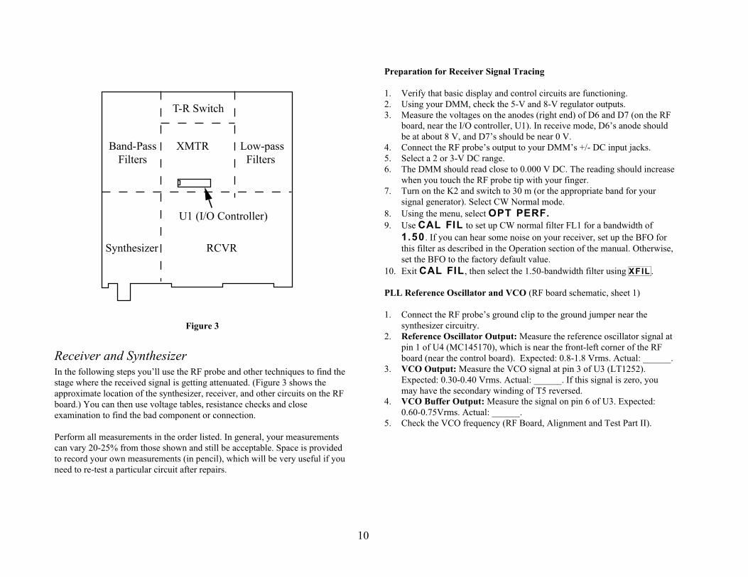
10
T-R Switch
Band-Pass XMTR Low-pass Filters Filters
U1 (I/O Controller)
Synthesizer RCVR
Figure 3
Receiver and SynthesizerIn the following steps you’ll use the RF probe and other techniques to find thestage where the received signal is getting attenuated. (Figure 3 shows theapproximate location of the synthesizer, receiver, and other circuits on the RFboard.) You can then use voltage tables, resistance checks and closeexamination to find the bad component or connection.
Perform all measurements in the order listed. In general, your measurementscan vary 20-25% from those shown and still be acceptable. Space is providedto record your own measurements (in pencil), which will be very useful if youneed to re-test a particular circuit after repairs.
Preparation for Receiver Signal Tracing
1. Verify that basic display and control circuits are functioning.2. Using your DMM, check the 5-V and 8-V regulator outputs.3. Measure the voltages on the anodes (right end) of D6 and D7 (on the RF
board, near the I/O controller, U1). In receive mode, D6’s anode shouldbe at about 8 V, and D7’s should be near 0 V.
4. Connect the RF probe’s output to your DMM’s +/- DC input jacks.5. Select a 2 or 3-V DC range.6. The DMM should read close to 0.000 V DC. The reading should increase
when you touch the RF probe tip with your finger.7. Turn on the K2 and switch to 30 m (or the appropriate band for your
signal generator). Select CW Normal mode.8. Using the menu, select O P T P E R F .9. Use C A L F I L to set up CW normal filter FL1 for a bandwidth of
1 . 5 0 . If you can hear some noise on your receiver, set up the BFO forthis filter as described in the Operation section of the manual. Otherwise,set the BFO to the factory default value.
10. Exit C A L F I L , then select the 1.50-bandwidth filter using X F I L .
PLL Reference Oscillator and VCO (RF board schematic, sheet 1)
1. Connect the RF probe’s ground clip to the ground jumper near thesynthesizer circuitry.
2. Reference Oscillator Output: Measure the reference oscillator signal atpin 1 of U4 (MC145170), which is near the front-left corner of the RFboard (near the control board). Expected: 0.8-1.8 Vrms. Actual: ______.
3. VCO Output: Measure the VCO signal at pin 3 of U3 (LT1252).Expected: 0.30-0.40 Vrms. Actual: ______. If this signal is zero, youmay have the secondary winding of T5 reversed.
4. VCO Buffer Output: Measure the signal on pin 6 of U3. Expected:0.60-0.75Vrms. Actual: ______.
5. Check the VCO frequency (RF Board, Alignment and Test Part II).
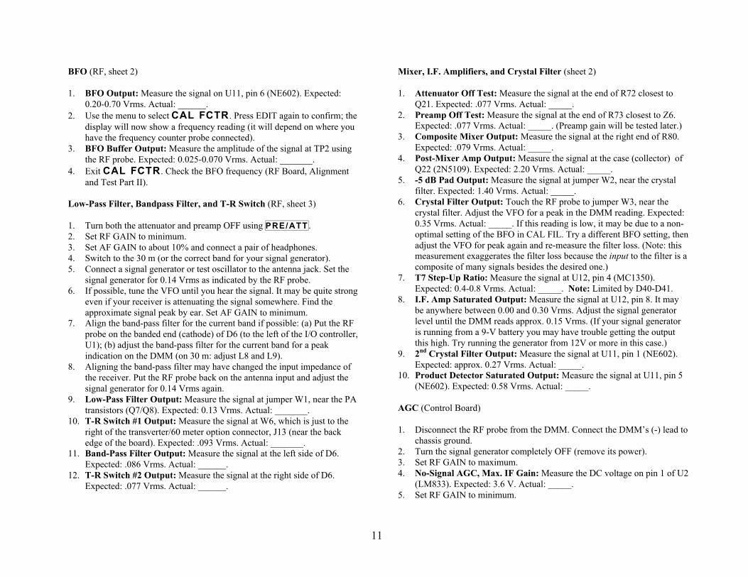
11
BFO (RF, sheet 2)
1. BFO Output: Measure the signal on U11, pin 6 (NE602). Expected:0.20-0.70 Vrms. Actual: ______.
2. Use the menu to select C A L F C T R . Press EDIT again to confirm; thedisplay will now show a frequency reading (it will depend on where youhave the frequency counter probe connected).
3. BFO Buffer Output: Measure the amplitude of the signal at TP2 usingthe RF probe. Expected: 0.025-0.070 Vrms. Actual: _______.
4. Exit C A L F C T R . Check the BFO frequency (RF Board, Alignmentand Test Part II).
Low-Pass Filter, Bandpass Filter, and T-R Switch (RF, sheet 3)
1. Turn both the attenuator and preamp OFF using P R E / A T T .2. Set RF GAIN to minimum.3. Set AF GAIN to about 10% and connect a pair of headphones.4. Switch to the 30 m (or the correct band for your signal generator).5. Connect a signal generator or test oscillator to the antenna jack. Set the
signal generator for 0.14 Vrms as indicated by the RF probe.6. If possible, tune the VFO until you hear the signal. It may be quite strong
even if your receiver is attenuating the signal somewhere. Find theapproximate signal peak by ear. Set AF GAIN to minimum.
7. Align the band-pass filter for the current band if possible: (a) Put the RFprobe on the banded end (cathode) of D6 (to the left of the I/O controller,U1); (b) adjust the band-pass filter for the current band for a peakindication on the DMM (on 30 m: adjust L8 and L9).
8. Aligning the band-pass filter may have changed the input impedance ofthe receiver. Put the RF probe back on the antenna input and adjust thesignal generator for 0.14 Vrms again.
9. Low-Pass Filter Output: Measure the signal at jumper W1, near the PAtransistors (Q7/Q8). Expected: 0.13 Vrms. Actual: _______.
10. T-R Switch #1 Output: Measure the signal at W6, which is just to theright of the transverter/60 meter option connector, J13 (near the backedge of the board). Expected: .093 Vrms. Actual: _______.
11. Band-Pass Filter Output: Measure the signal at the left side of D6.Expected: .086 Vrms. Actual: ______.
12. T-R Switch #2 Output: Measure the signal at the right side of D6.Expected: .077 Vrms. Actual: ______.
Mixer, I.F. Amplifiers, and Crystal Filter (sheet 2)
1. Attenuator Off Test: Measure the signal at the end of R72 closest toQ21. Expected: .077 Vrms. Actual: _____.
2. Preamp Off Test: Measure the signal at the end of R73 closest to Z6.Expected: .077 Vrms. Actual: _____. (Preamp gain will be tested later.)
3. Composite Mixer Output: Measure the signal at the right end of R80.Expected: .079 Vrms. Actual: _____.
4. Post-Mixer Amp Output: Measure the signal at the case (collector) ofQ22 (2N5109). Expected: 2.20 Vrms. Actual: _____.
5. -5 dB Pad Output: Measure the signal at jumper W2, near the crystalfilter. Expected: 1.40 Vrms. Actual: _____.
6. Crystal Filter Output: Touch the RF probe to jumper W3, near thecrystal filter. Adjust the VFO for a peak in the DMM reading. Expected:0.35 Vrms. Actual: _____. If this reading is low, it may be due to a non-optimal setting of the BFO in CAL FIL. Try a different BFO setting, thenadjust the VFO for peak again and re-measure the filter loss. (Note: thismeasurement exaggerates the filter loss because the input to the filter is acomposite of many signals besides the desired one.)
7. T7 Step-Up Ratio: Measure the signal at U12, pin 4 (MC1350).Expected: 0.4-0.8 Vrms. Actual: _____. Note: Limited by D40-D41.
8. I.F. Amp Saturated Output: Measure the signal at U12, pin 8. It maybe anywhere between 0.00 and 0.30 Vrms. Adjust the signal generatorlevel until the DMM reads approx. 0.15 Vrms. (If your signal generatoris running from a 9-V battery you may have trouble getting the outputthis high. Try running the generator from 12V or more in this case.)
9. 2nd Crystal Filter Output: Measure the signal at U11, pin 1 (NE602).Expected: approx. 0.27 Vrms. Actual: _____.
10. Product Detector Saturated Output: Measure the signal at U11, pin 5(NE602). Expected: 0.58 Vrms. Actual: _____.
AGC (Control Board)
1. Disconnect the RF probe from the DMM. Connect the DMM’s (-) lead tochassis ground.
2. Turn the signal generator completely OFF (remove its power).3. Set RF GAIN to maximum.4. No-Signal AGC, Max. IF Gain: Measure the DC voltage on pin 1 of U2
(LM833). Expected: 3.6 V. Actual: _____.5. Set RF GAIN to minimum.

12
6. No-Signal AGC, Min. IF Gain: Measure the DC voltage on pin 1 of U2.Expected: 4.6 V. Actual: _____.
7. Turn the signal generator back on.8. AGC @ Saturation: Measure the DC voltage on pin 1 of U2. Expected:
6.9 V. Actual: _____. Adjust the VFO to make sure this voltage is at itspeak.
9. I.F. Amp AGC Input: Measure the DC voltage on pin 5 of U12 (RF,sheet 2). Expected: 5.0 V. Actual: _____.
Product Detector and AF Amp (RF, Sheet 2)
1. Set up the DMM to read AC volts (use a 2 or 3-V meter range).2. Touch the (+) lead of the DMM to pin 5 of U11 (NE602). Decrease the
signal generator level until the AC voltage at pin 5 reads .025 Vrms. (TheK2’s RF GAIN control should still be at minimum.)
3. Disconnect the headphones and speaker. Turn the AF GAIN control tomaximum.
4. Measure the signal at the speaker jack, P5 pin 1 (near the on/off switch,S1). Expected: 1.6 Vrms. Actual: _____.
I.F. Amp Noise Gain (RF, sheet 2)
1. Turn the signal generator off and disconnect it from the antenna jack.Connect a 50-ohm dummy load.
2. Turn off all nearby equipment (especially computers or signal sources).3. Set AF GAIN to maximum. Set RF GAIN to minimum.4. Make sure the preamp and attenuator are both OFF.5. Verify that FL1 is selected (bandwidth = 1.50), as well as CW Normal
mode.6. AF Output, Min. IF gain: Setup the DMM for its lowest AC volts
range. Measure the signal at the speaker jack, P5 (near the on/off switch,S1). Expected: 0.000-0.001 Vrms. Actual: _____.
7. AF Output, Max. IF gain: Set RF GAIN to maximum. Measure thesignal at P5, pin 1. Expected: 0.007-0.013 Vrms. Actual: _____.
8. Preamp Noise Gain: Turn on the preamp. Measure the signal at P5.Expected: 0.030-0.060 Vrms. Actual: _____.
9. Noise Increase w/Antenna: Connect an antenna. The signal at P5 shouldincrease substantially even if atmospheric conditions are quiet. A typicalreading on 30 or 40 m is 0.20-0.40 Vrms. In general, the longer or higheryour antenna is, the greater the noise increase will be.
Final Steps
If you have completed receiver signal tracing and any necessary repairs, youshould then do the following:
1. Re-install the bottom cover and heat sink.2. Re-do calibration of the VCO, BFO, band-pass filters, crystal filters, etc.
as needed (see RF Board Alignment and Test, parts I, II, and III). If youpeaked L8 and L9 when signal tracing through the 30-m band-pass filter,you’ll need to re-peak C21 and C23 on 20 m.
3. Leave the frequency counter cable connected to TP2 (BFO)4. Connect the speaker and re-install the top cover.
TransmitterThe following procedure can be used to isolate problems with the transmitter(the transmitter area of the RF board is identified in Figure 3). CW mode isused for these tests. If you’re having difficulty with the SSB adapter, makesure the transmitter works on CW first, then proceed with the signal tracinginstructions in the SSB adapter manual.
Once you find a location where the signal appears to be much lower thanexpected, stop signal tracing and check that circuit. Check all componentvalues and DC voltages (see DC Voltage Tables). Closely examine the PCboard for unsoldered pins and solder bridges. One of most likely causes of atransmitter problem is a poorly-soldered toroid lead. Re-heat any suspectleads or solder joints.
Preparation for Transmitter Signal Tracing
1. Make sure basic display and control circuits are functioning beforeattempting transmitter testing.
2. Remove the SSB adapter (if installed) and install temporary jumpers atJ9 and J10. Temporarily re-install C167 (.001 µF or higher) between pins7 and 12 of J11. (See RF board, sheet 2.)
3. 12 V supply check: Use your DMM to check the DC voltage at thecathode (banded end) of D10 (right edge of the board). Expected: 9 to 14V. Actual: _____. Verify that the same voltage (or slightly lower) can befound on the case (collector) of Q5 and the tab (collector) of Q6 when theK2 is turned on and is in receive mode.

13
4. If you don’t have an RF probe, you can build the one from Figure 1.Note: do not use the RF probe to directly measure the transmitter’spower output unless you have the power set for 2 W or less. The 1N34Adiode in the RF probe may be damaged at higher power levels.
5. Test Shared Circuits: Do the receiver signal tracing (above). This testsa number of circuits that are shared by both transmitter and receiver,including the VCO, BFO, BFO buffer, T-R switches, band-pass filters,and low-pass filters. It’s important not to skip this step, even if thereceiver seems to be working correctly. Shared circuits that are workingmarginally may affect the transmitter more than the receiver, so theiractual output levels must be measured.
6. Set up the K2 for 40 meters (about 7100 kHz), CW Normal mode.7. Plug in a 50-ohm dummy load (10-W or higher rating).8. Set the power level to 5 watts.9. Connect a hand key or keyer paddle to the key jack.10. Connect a speaker or headphones.11. Use the menu to set S T L 030, S T P 0.50, and T - R 0.05.12. Select hand key mode (I N P H A N D ).13. Set up a transmit current limit of 2.50 amps using C A L C U R .
Basic voltage checks (RF schematic, sheet 2)
Note: When using T U N E to key the transmitter, be sure to tap T U N E againwithin 5 seconds or less each time. This will reduce the chance of damagingany components in the transmitter that are consuming excess power.
1. Switch to voltage/current display mode using D I S P L A Y .2. Hold T U N E to key the transmitter, and verify that supply voltage does
not drop by more than about 0.8 V. If it drops more than this, either yourpower supply is inadequate or the transmitter is drawing excess current.Actual transmit-mode voltage: _____ V. Current: _____ A.
3. Return to normal display mode using D I S P L A Y .4. Measure the key-down DC voltages on the anodes (right end) of D6 and
D7 (near U1, the I/O controller). During transmit, the voltage on theanode of D7 should be about 8 V, and on D6, near 0 V. Actual TX-modevoltages, D6: _____ V; D7: _____ V.
5. Use T U N E and note the actual power output: _____ W.
Sidetone (Control Board)
Note: If the sidetone is already functioning correctly, you can skip thissection.
1. Make sure you’re in CW mode. The sidetone will not function in SSBmodes.
2. Disconnect the headphones and speaker.3. Use the menu to set S T L to 255 (maximum sidetone level).4. Use the V O X button to select CW TEST mode (the mode letter will then
flash). This is a safe setting for sidetone tests, since there is no poweroutput.
5. Set your DMM for AC volts, 2 or 3-V range. Touch the positive lead ofthe DMM to pin 25 of U6 on the control board (18C452). (This is thesource of the sidetone signal.)
6. Key the transmitter using the hand key (T U N E does not activate thesidetone). Measure the AC voltage on pin 25 of U6. Expected: 2.5 Vrms.Actual: _____. Un-key the transmitter.
7. Move the DMM probe to the drain of Q5 (control board, 2N7000). Keythe transmitter and measure the AC drain voltage. Expected: 2.4 Vrms.Actual: _____. If this is zero, either Q5 is defective or there is no drainvoltage supply from pin 1 of U8 (MAX534, D-to-A converter).
8. Measure the AC voltage on pin 7 of U10 (LMC660). Expected: 0.5Vrms. Actual: _____.
9. Measure the AC voltage on pin 8 of U9 (LM380). Expected: 0.5 Vrms.Actual: _____.
10. Measure the AC voltage on pin 6 of U9. Expected: 0.5 Vrms. Actual:_____. This signal should also be present on the speaker jack, P5 pin 1(RF board).
11. Return the S T L setting to 030.12. Use the V O X button to put the transmitter back into O P E R a t e mode.
ALC (control board)
1. Make sure the POWER control is set for 5 watts, and that you’re inCW/Operate mode.
2. Set up the DMM for DC volts, 20 or 30-V range.3. Power Control Test (VPWR line): The VPWR line, pin 2 of U8
(MAX534), is where transmit power control begins. On key-down, themicroprocessor (U6) starts increasing the voltage on VPWR until it seesthe desired power indication from the RF output detector (RF board,

14
sheet 3, lower right-hand corner). To test VPWR, set the DMM for DCvolts, then measure the DC voltage on pin 2 of U8 when T U N E ispressed. Expected: 0.7-2.5 VDC. Actual: _____.
4. If VPWR reading is high (> 4.5 V): The ALC software will set VPWRto its highest level (about 5 V) if the transmitter cannot be driven to therequested power level. This happens for one of two reasons: (a) thetransmitter gain is low (or transmitter isn’t working at all); (b) the RFdetector has an incorrect component. Check all component values in theRF detector. If you can’t find a problem with the RF detector, continuewith the next signal tracing section (transmit mixer, etc.).
5. If VPWR reading is low (< 0.4V): VPWR can be too low because: (a)the ALC software is being “fooled” by a signal from the RF detector thatsays the power is higher than it really is; (b) because U8 on the controlboard is defective or has a pin shorted to ground or not soldered. Checkall component values in the RF detector (RF, sheet 3). If these appearcorrect, check DC voltages on U8 (control), as well as resistance toground on all pins.
Transmit Mixer, Buffer, Band-Pass Filter, T-R Switch (RF, sheets 2-3)
Note: The measurements in this section and the next may vary widely,especially if you do the measurements on a band other than 40 m. However,the ratio between any two back-to-back measurements should remain fairlyconstant, and is a good indication of gain or loss of a stage in the transmitter.For example, the ratio of measurements in steps 3 and 2 below is about 12.
1. Connect the RF probe to the DMM. Set the DMM for a 2 or 3-V DCvolts range.
2. Xmit Mixer Output: Measure the key-down signal at U10, pin 4.Expected: 0.016 Vrms. Actual: _____.
3. Buffer Output: Measure the key-down signal at U9, pin 6 (LT1252).Expected: 0.200 Vrms. Actual: _____.
4. Band-Pass Filter Output: Measure the key-down signal at W6.Expected: 0.030 Vrms. Actual: _____.
5. T-R Switch #1 Output: Measure the key-down signal at the anode ofD1. Expected: 0.029 Vrms. Actual: _____.
Pre-driver, Driver, and PA (RF, sheet 4)
1. Pre-Driver Output: Measure the key-down signal at the case (collector)of Q5 (2N5109). Expected: 0.120 Vrms. Actual: _____.
2. Driver Input: Measure the key-down signal on the base of Q6(2SC2166; pins are labeled B, C, E). Expected: 0.026 Vrms. Actual:_____.
3. Driver Output: Measure the key-down signal at the tab (collector) ofQ6. Expected: 1.8 Vrms. Actual: _____.
4. PA Input (Q7): Measure the key-down signal at the base of Q7(2SC1969 on bottom of the board; pins are labeled on the top). Expected:0.38 Vrms. Actual: _____.
5. PA Input (Q8): Measure the key-down signal at the base of Q8.Expected: 0.38 Vrms. Actual: _____.
6. RF Detector Input: Measure the key-down signal on the anode (non-banded end) of D9 (1N5711, middle of the right edge of the board).Expected: 2.0 Vrms. Actual: _____. (This voltage should be fairlyconstant regardless of the band used.)
7. PA Transistor Tests: If the PA input voltages were higher thanexpected, but the RF detector input was too low, one or both PAtransistors could be defective. After checking DC voltages andtransformer leads, turn off power to the K2 and use your DMM’sdiode/transistor test range to test the transistors. With the DMM’spositive lead on the base of Q7, you should measure about 0.6 k to theemitter or collector. With the DMM’s negative lead on the base of Q7,you should measure about 1.3 k to the emitter and > 3 k to the collector.These also apply to Q8.
DC Voltage TablesThe tables on the following pages provide DC voltages for all ICs andtransistors on each of the three boards, as well as the diodes in the T-R switch(RF board). Typically, your readings will match these within 10%.Thevoltages were measured using a high-impedance DMM (10-11 Megohm).The K2’s internal voltmeter can also be used for most measurements.
Receive-mode voltages are listed except as noted. Most of the Control boardmeasurements were made with the Front Panel module removed for easieraccess. Exceptions are indicated by (**).
Equipment Setup: Supply voltage 14.0 V; no antenna; LCD = NITE; GRPH= DOT; receive mode; no headphones or speaker connected; RF GAIN mid-range; AF GAIN minimum; OFFSET mid-range.
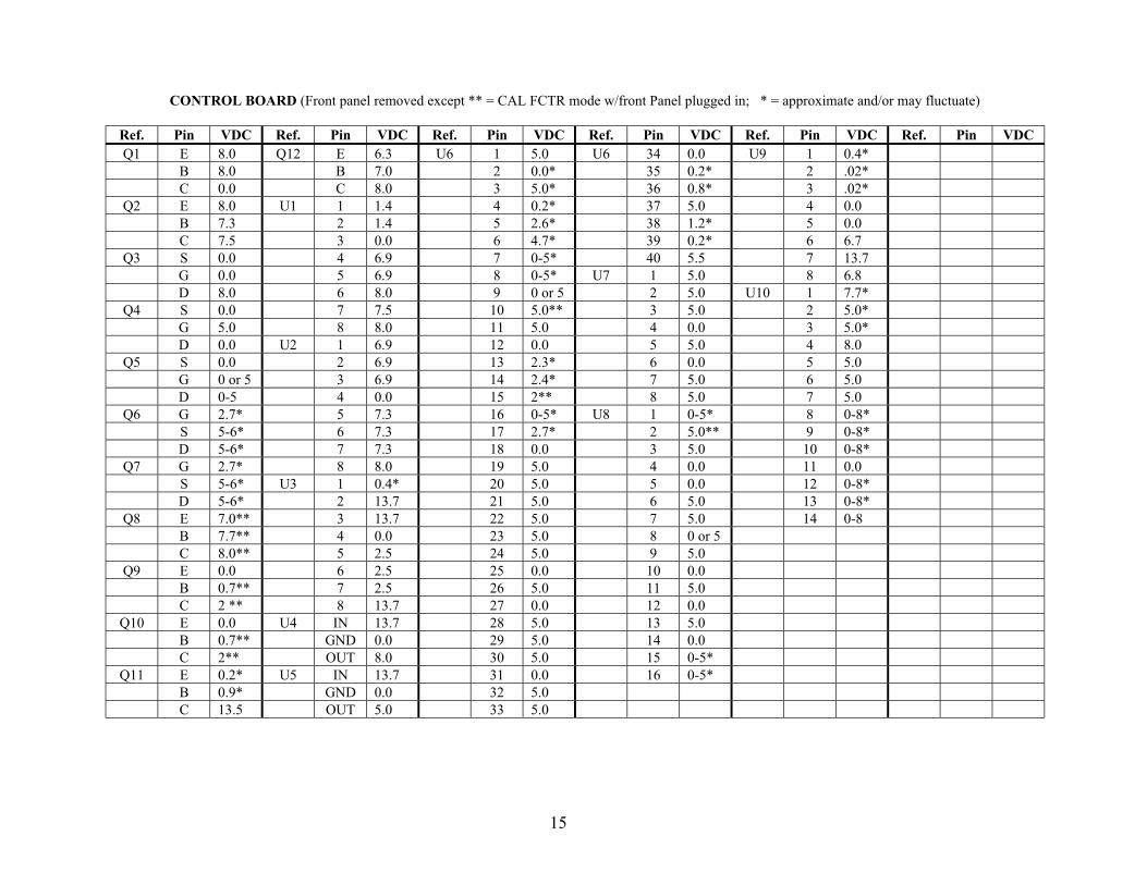
15
CONTROL BOARD (Front panel removed except ** = CAL FCTR mode w/front Panel plugged in; * = approximate and/or may fluctuate)
Ref. Pin VDC Ref. Pin VDC Ref. Pin VDC Ref. Pin VDC Ref. Pin VDC Ref. Pin VDCQ1 E 8.0 Q12 E 6.3 U6 1 5.0 U6 34 0.0 U9 1 0.4*
B 8.0 B 7.0 2 0.0* 35 0.2* 2 .02*C 0.0 C 8.0 3 5.0* 36 0.8* 3 .02*
Q2 E 8.0 U1 1 1.4 4 0.2* 37 5.0 4 0.0B 7.3 2 1.4 5 2.6* 38 1.2* 5 0.0C 7.5 3 0.0 6 4.7* 39 0.2* 6 6.7
Q3 S 0.0 4 6.9 7 0-5* 40 5.5 7 13.7G 0.0 5 6.9 8 0-5* U7 1 5.0 8 6.8D 8.0 6 8.0 9 0 or 5 2 5.0 U10 1 7.7*
Q4 S 0.0 7 7.5 10 5.0** 3 5.0 2 5.0*G 5.0 8 8.0 11 5.0 4 0.0 3 5.0*D 0.0 U2 1 6.9 12 0.0 5 5.0 4 8.0
Q5 S 0.0 2 6.9 13 2.3* 6 0.0 5 5.0G 0 or 5 3 6.9 14 2.4* 7 5.0 6 5.0D 0-5 4 0.0 15 2** 8 5.0 7 5.0
Q6 G 2.7* 5 7.3 16 0-5* U8 1 0-5* 8 0-8*S 5-6* 6 7.3 17 2.7* 2 5.0** 9 0-8*D 5-6* 7 7.3 18 0.0 3 5.0 10 0-8*
Q7 G 2.7* 8 8.0 19 5.0 4 0.0 11 0.0S 5-6* U3 1 0.4* 20 5.0 5 0.0 12 0-8*D 5-6* 2 13.7 21 5.0 6 5.0 13 0-8*
Q8 E 7.0** 3 13.7 22 5.0 7 5.0 14 0-8B 7.7** 4 0.0 23 5.0 8 0 or 5C 8.0** 5 2.5 24 5.0 9 5.0
Q9 E 0.0 6 2.5 25 0.0 10 0.0B 0.7** 7 2.5 26 5.0 11 5.0C 2 ** 8 13.7 27 0.0 12 0.0
Q10 E 0.0 U4 IN 13.7 28 5.0 13 5.0B 0.7** GND 0.0 29 5.0 14 0.0C 2** OUT 8.0 30 5.0 15 0-5*
Q11 E 0.2* U5 IN 13.7 31 0.0 16 0-5*B 0.9* GND 0.0 32 5.0C 13.5 OUT 5.0 33 5.0

16
FRONT-PANEL BOARD (* = approximate and/or may fluctuate; ** = not accessible due to LCD)
Ref. Pin VDC Ref. Pin VDC Ref. Pin VDC Ref. Pin VDC Ref. Pin VDC Ref. Pin VDCQ1 E 2.7 U1 26 3.5 U3 1 0.0 U4 15 0.0
B 3.4 27 3.5 2 5.0 16 0.0C 5.0 28 3.5 3 0.8* 17 0.0
Q2 E 2.7 29 3.5 4 > 0 18 0.4*B 3.4 30 3.5 5 > 0 19 0.0C 5.0 31 3.5 6 4.0* 20 0.0
32 3.5 7 2.0*33 3.5 8 5.034 3.5 9 0.0
U1 1 ** 35 3.5 10 0.02 ** 36 3.5 11 0.03 ** 37 3.5 12 .02*4 ** 38 3.5 13 0.2*5 ** 39 3.5 14 3.1*6 ** 40 3.5 15 0.8*7 ** U2 1 5.0 16 4.0*8 ** 2 0.2* 17 0.19 ** 3 5.0 18 3.6*10 ** 4 5.0 19 0.011 ** 5 5.0 20 0.012 ** 6 5.0 U4 1 0.013 ** 7 5.0 2 5.014 ** 8 0.0 3 3.6*15 ** 9 0.1* 4 > 016 ** 10 0.0 5 > 017 ** 11 5.0 6 > 018 ** 12 5.0 7 > 019 ** 13 5.0 8 5.020 ** 14 5.0 9 0.021 3.5 15 0.0 10 0.022 3.5 16 5.0 11 0.023 3.5 12 .02*24 3.5 13 0.2*25 3.5 14 0.0

17
RF BOARD (Shaded areas indicate transmit-mode voltage measurements)
Ref. Pin VDC Ref. Pin VDC Ref. Pin VDC Ref. Pin VDC Ref. Pin VDC Ref. Pin VDCD1 A 0.0 Q12 S 0.0 U1 1 6.0 U3 6 4.3 U8 IN 8.0
C 7.5 G 6.0 2 6.0 7 8.0 GND 0.0D2 A 8.0 D 0.0 3 0.0 8 0.0 OUT 5.0
C 7.5 Q13 E 0.6 4 0.0 U4 1 2.1 U9 1 0.0D3 A 8.0 B 1.3 5 0.0 2 2.4 2 6.9
C 7.5 C 7.5 6 0.0 3 0.0 3 6.9D4 A 8.0 Q16 E 0.0 7 0.0 4 2.3 4 0.0
C 7.5 B 0.6 8 0.0 5 5.0 5 0.0D5 A 0.0 C 2.2 9 0.2 6 5.0 6 6.9
C 8.0 Q17 S 0.0 10 0.15 7 0.0 7 13.8D6 A 8.0 G 2.2 11 0.0 8 0.1 8 0.0
C 7.5 D 2 to 3 12 0.0 9 0.0 U10 1 1.4D7 A 0.0 Q18 G -1.0 13 0.0 10 0.0 2 1.4
C 7.5 S 2 to 3 14 0.0 11 0.0 3 0.0Q2 S 0.0 D 6.3 15 0.0 12 0.0 4 5.0
G 8.0 Q19 G 0.0 16 0.0 13 4.0 5 5.0D 0.0 S 0.8 17 0.0 14 5.0 6 6.0
Q5 E 0.6 D 8.0 18 6.0 15 5.0 7 5.5B 1.3 Q20 S 0.0 19 0.0 16 5.0 8 6.1C 12.4 G 8.0 20 6.0 U5 1 0.0 U11 1 1.4
Q6 B 1.1 D 0.0 21 0.0 2 5.0 2 1.4C 13.3 Q21 E 1.6 22 0.0 3 5.0 3 0.0E 0.4 B 2.3 23 0.0 4 5.0 4 5.0
Q7 B 0.6 C 13.2 24 0.0 5 0.0 5 5.0C 13.4 Q22 E 1.3 25 0.0 6 2.0 6 6.1E 0.0 B 2.0 26 0.0 7 0 to 4 7 5.6
Q8 B 0.6 C 12.5 27 0.0 8 5.0 8 6.1C 13.4 Q23 S 0.0 28 5.5 U6 1 0 to 8 U12 1 7.9E 0.0 G 0.0 U2 IN 13.7 2 0 to 4 2 7.9
Q10 S 1.6 D 8.0 GND 0.0 3 0 to 4 3 0.0G 8.1 Q24 G 0.0 OUT 6.0 4 0.0 4 2.5D 1.6 S 1.2 U3 1 0.0 5 4.0 5 3.9
Q11 E 0.0 D 1.3 2 4.3 6 4.0 6 2.5B 0.6 3 4.1 7 0 to 8 7 0.0C 1.3 4 0.0 8 8.0 8 7.9
5 0.0

U1
AN
D IT
S S
OC
KE
T A
RE
MO
UN
TE
D
INS
TALL
SO
CK
ET
FIR
ST
FRO
NT
PA
NE
L B
OA
RD
ON
TH
E O
THE
R S
IDE
BE
VE
LED
CO
RN
ER
2002
ELE
CR
AF
TK
2 R
F R
ev. B
16C
72 (
SO
CK
ET
)
2002
ELE
CR
AF
T
2002
ELE
CR
AF
TK
2 C
ON
TRO
L
PIC
18C
452
AU
X 1
2V
RF
Pro
be
Ele
cra
ft
CO
NTR
OL
CO
UN
TER
14
51
70
BO
AR
D
MA
X5
34
LMC
660 K
2 F
PR
ev. B
Rev
. B
LIN
EA
R
LIN
EA
RLI
NE
AR
LIN
EA
R
RF
C14
RF
C13
RF
C16
AU
DIO
1N
34
A
SPKR
R1
15
10
0K
10
0K
C2
21
C1
92
C1
06
C2
03
C2
14
C2
22
C2
20
C1
97
C2
18
C2
02
C1
99
C2
12
C1
14
C1
91
C1
90
RFC
3
LIFT
C2
26
C2
27
C1
26
C1
96
C1
81
C1
65
C1
66
R1
11
C1
62
R1
07
10
0K
C2
25
C1
58
C1
41
C1
76
C1
72
C1
55
R1
01
C1
78
C1
53
C1
69
C1
60
C1
40
12
52
12
52
C2
01
C1
05
C1
75C
15
4
C1
00
14
51
C1
77
C1
68
C1
44
C1
67
C1
39
C1
38
C1
37
C1
16
C1
24
C1
11
R79
C1
63 C1
64
3.9
K
64
82
78
05
29
30
C1
46
R1
13
C1
70
C1
25
5.1
K
4.7
M
C2
29
R36
R35
L1
1
L1
3
K1
4K
13
K1
5
X1
0
X1
1
RP
4
RP
5
C7
1
C3
9
C1
3
C3
5
C3
1
C4
8
C4
7
K1
0
K1
1
L3
0
R38
J14
C1
5C
24
C4
2
C4
3
L1
0
L1
2
C3
6
C2
2
C2
5C
34
C4
4C
46
C3
3
C4
5
C3
2
R37
L1
7
L2
0
L1
9L
18
L2
1
L2
2 L2
4L
23
K1
2L
25
L3
4
R88
R81
R89
R90
J12
J10
Q2
2
R85
R84
R83
R68
R67
RP
6
K1
6K
17
C7
7R
73C
57
J13
J11
R93
C5
5C
52
C5
3
R80
R97
SSB
R64
D1
1
D2
1
D2
2
D2
3D
25
D2
4D
26
D3
7D
38
D3
9
D3
3
D3
2
D3
1
D3
0
D2
9
RP
31
0K
D1
6D
17
C8
6
R11
R12
R13
R14
R15
R25
R28
C8
9
R17
C9
2
C6
3
R24
C6
4
C6
7
C7
9C
81
R22
RP
2C9
6
C9
4
C9
5
R30
R33
R32
R31
C9
3
C8
5
C8
4
R21
66
2
C6
1
C5
8
R16
R10
C5
9
C8
0C
82
R82
C1
18
0m
C1
9C
37
C3
0
R91
Q2
4
Q1
9
Q1
6Q
17
Q2
0
R39
AU
XR
F
R62
Q1
0
Q1
1Q
13
R61
R59
R92
R78
R46
R41
R40
R45
RP
28
2K
U1
0
RP
1
C2
9
C3
2
32
0
38
0
C2
2C
38
C1
0
C1
9
C2
1
C3
5C
28
R17
R16
C3
0
R20
C3
3
R10
C1
8
Q1
1
C1
7
C1
5C
14
C1
6
C3
6
J1
J2
RP
34
7K
C4
1R
P4 82
K
Q1
0
RP
6
C1
1
C4
0
RP
54
70
C3
9
R12
S1
0
S1
1S
12
S1
3
S1
4S
15
S1
6
DS
2
DS
1
RP
21
20
R10
RP
31
0K
R14
R13
R11
Q2
1
RP
73
3K
C2
4
C2
0
Q2
3
Q1
2
TP
2
TP
1
TP
3
R20
C4
2
D1
2
.01
TIP
Q2
5
J15
INT
EX
T1
2V
R60
D1
9
D2
0
10
K
C4
4
J2
S1
J7
J8
K1
K2
K7K5
K6
K4
K3
L2
L4
L9
U4
X7
X8
X9
J4
U5
U6
U3
U9
C8
C4
C7
K9
T1
T2
D2
Q6
T5
K8
C5
L3
L8
L1
D4
J6
Z6
U1
Z5
P6 P3
D9
X4X3
X5
X6
J9
T7
D7
D6
R7
R6
T6
J5
J1R
1 R2
W2
W3
W1
X2X1
R9
L5
C9
T3
Q7
Q8Z1
Z2
T4
U8
U2
D1
D3
Q2
Q5
W5
X2
P2
P3
U6
U8
Q6
Q7
Q1 Q
2
U7
U3
U9
15
25
P1
Q9
Q8
X1
C1
C7
C6
Q3
Q4
C2
D2
U5
U4
8V
5V
R7
R9
R8
C9
R6
40
25
R5
R2
C3
P4
C4
D1
D2
D3
S1
S2
S3
S4
S6
S5
S8
S9
R2
R1
R3
R4
R5
J2
C2
U3
C5
C6
C4
C7
S7
10
20
R9
C8 Q3
Q1
Q2
R6
R7
C1
D4
D5
D6
Z1
C3
P5
D3
Q5
R3
R8
P6
P5
R4
J3
F1
E1
E2
C1
R1
D1
C8R
1L
1
P7
1 1
1 2
3 4
1 2
3 4
B C E B C E
BC
E
+
1 2
3 4
11
+
+-
1
12
34
1
1
+
1
1+
+
1
1 2
3 4
56 7
8
+
1
1
1A
CB
D
1
11
1
1
+
+
+
1
++
+
1
1
1
1+
+
+1
1
1
1
12
34
CC
C
1
+
+
Appendix F Parts Placement Drawing, Top

X
Appendix F Parts Placement Drawing, Bottom