mahalakshmimahalakshmiengineeringcollege.com/pdf/eee/visem/ee2354/unit 5.pdf · unit 5 –...
TRANSCRIPT

EE2324/ Microprocessors & Microcontrollers Department of EEE 1
MAHALAKSHMI
ENGINEERING COLLEGE
TIRUCHIRAPALLI-621213.
QUESTION BANK
DEPARTMENT: EEE YR/ SEM:III/ VI
SUB CODE: EE2324 SUB NAME: MICROPROCESSORS & MICROCONTROLLERS
UNIT 5 – MICROCONTROLLER PROGRAMMING & APPLICATIONS
PART A (2 Marks)
1. What is program status word in 8051 microcontroller?(AUC MAY 2012)
Program Status Word (PSW) register is an 8 bit register. It is also referred to as the
flag register. Although it is 8 bit wide, only 6 of its bits are used. The two unused bits
are user definable flags. Four of the flags are called conditional flags.
EE2324/ Microprocessors & Microcontrollers Department of EEE 2
2. What are the applications of 8051 microcontroller? (AUC MAY 2012)
i) Traffic light control
ii) Stepper motor control
iii) Relay control
iv) Washing machine control
v) Factory automations
3. Why do we need opto-isolator circuit between microcontroller & stepper motor?(AUC
NOV 2011)
Motors can produce back EMF, a high voltage spike produced by sudden change of
current. To reduce the effect of this unwanted voltage spike opto isolators are used.
Opto isolators are widely used to isolate the stepper motor’s EMF voltage and keep it
from damaging the digital / microcontroller system
4. Mention the I/O instructions of 8051 microcontroller. (AUC NOV 2011)
MOVX instruction is the I/O instruction of 8051 microcontroller.
5. What is the operation of the given 8051 microcontroller instructions: XRL A, direct?
(AUC MAY 2011)
The contents of the address specified by direct is XORed with the contents of A
register and the result is stored in A register.
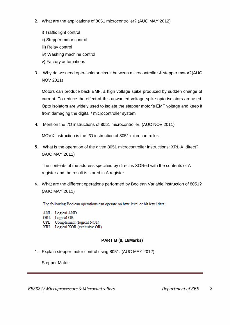
6. What are the different operations performed by Boolean Variable instruction of 8051?
(AUC MAY 2011)
PART B (8, 16Marks)
1. Explain stepper motor control using 8051. (AUC MAY 2012)
Stepper Motor:

EE2324/ Microprocessors & Microcontrollers Department of EEE 3
A stepper motor is a widely used device that translates electrical pulses into
mechanical movement. Stepper motor commonly have a permanent magnet rotor
called as shaft surrounded by a stator. There are also steppers called variable
reluctance stepper motors that do not have PM rotor. Most stepper motors have four
stator windings that are paired with a centre tap. This type is called four phase or
unipolar stepper motor. The centre tap allows change of current direction in each of
two coils when a winding is grounded, thereby resulting in a polarity change of the
stator. The direction of the rotation is dictated by the stator poles. The stator poles
are determined by the current sent through the wire coils. As the direction of current
is changed, the polarity is also changed causing the reverse motion of the rotor. The
stepper motor discussed here has 6 leads: 4 leads representing the four stator
windings and 2 commons for the centre tap leads. As the sequence of power is
applied to each stator winding, the rotor will rotate. The below table shows a 2 phase,
4 step stepping sequence.
Clo
ckw
ise
Dire
ctio
n
STEP Winding A Winding B Winding C Winding D
An
ti c
lockw
ise
dire
ctio
n
1 1 0 0 1
2 1 1 0 0
3 0 1 1 0
4 0 0 1 1

EE2324/ Microprocessors & Microcontrollers Department of EEE 4
Step Angle:
This depends on the internal construction of the motor, in particular the number of
teeth on the stator and the rotor. The step angle is the minimum degree of rotation
associated with a single step. The total number of steps needed to rotate one
complete revolution or 360 degrees is called steps per revolution.
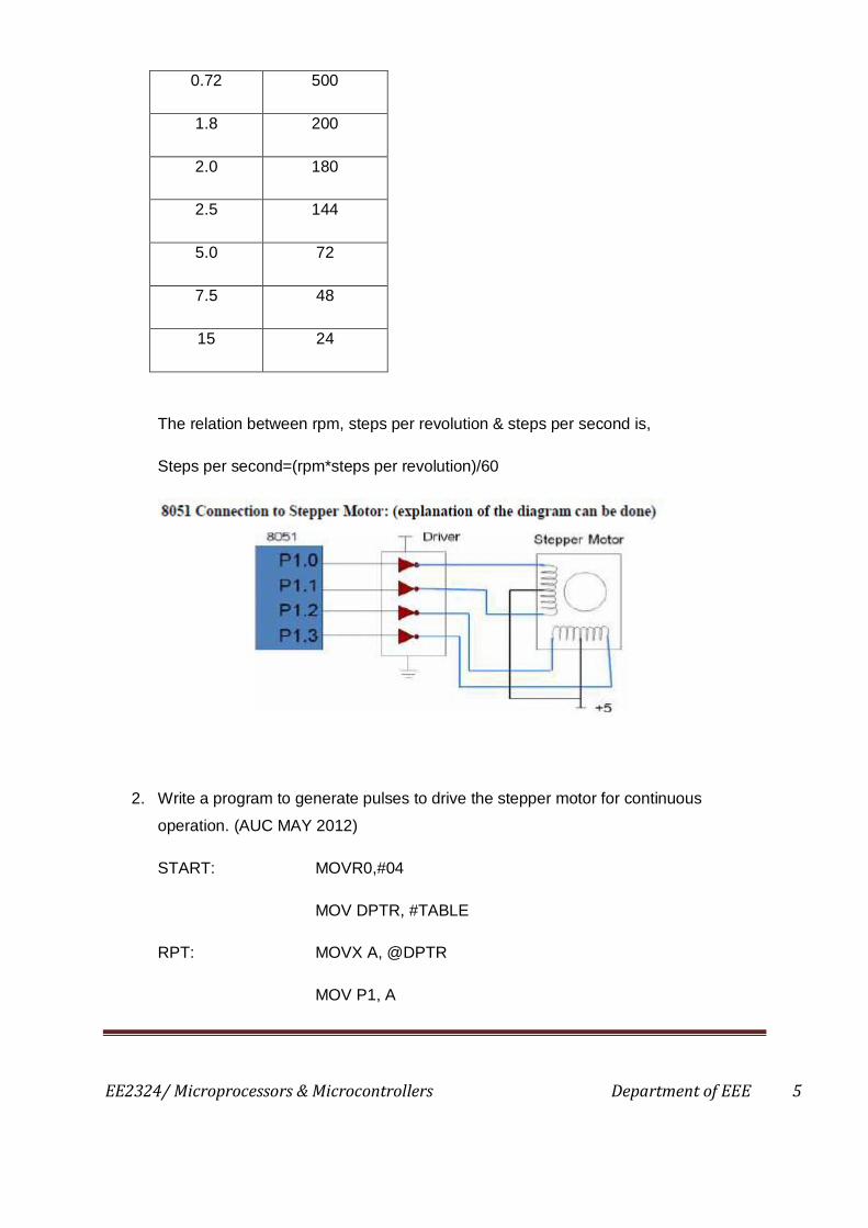
Step angle Steps per
revolution
EE2324/ Microprocessors & Microcontrollers Department of EEE 5
0.72 500
1.8 200
2.0 180
2.5 144
5.0 72
7.5 48
15 24
The relation between rpm, steps per revolution & steps per second is,
Steps per second=(rpm*steps per revolution)/60
2. Write a program to generate pulses to drive the stepper motor for continuous
operation. (AUC MAY 2012)
START: MOVR0,#04
MOV DPTR, #TABLE
RPT: MOVX A, @DPTR
MOV P1, A

EE2324/ Microprocessors & Microcontrollers Department of EEE 6
ACALL DELAY
INC DPTR
DJNZ R0, RPT
SJMP START
TABLE: DB 09 05 06 0A
DELAY: MOV R2, #64H
L1: MOV R3, #FFH
L2: DJNZ R3, L2
L2: DJNZ R2, L1
RET
3. Explain with a neat diagram the applications of 8051 microcontroller in Washing
Machine Control. (AUC MAY 2012, NOV 2011)
Washing machine control
AT89S51 microcontroller is used to control the process of washing cycle and to drive
the external output devices such as water inlet valve, wash motor, water drain valve.
The control strategy program for AT89S51 microcontroller is implemented by using
assembly language. The objectives of this development are to design a simple
control system using low cost microcontroller, to construct the functions of system
using simple control system. The main abstraction of this research is to improve
control and software systems of microcontroller based process simple control system
in Electronics.
Abstract
Washing machines are a common feature today in the Indian household. The most
important utility a customer can derive from a washing machine is that he saves the
effort he/she had to put in brushing, agitating and washing the cloth. Most of the
people wouldn’t have noticed (but can reason out very well) that different type of
cloth need different amount of washing time which depends directly on the type of
dirt, amount of dirt, cloth quality etc. The washing machines that are used today (the
one not using fuzzy logic control) serves all the purpose of washing, but which cloth

EE2324/ Microprocessors & Microcontrollers Department of EEE 7
needs what amount of agitation time is a business which has not been dealt with
properly. In most of the cases either the user is compelled to give all the cloth same
agitation or is provided with a restricted amount of control. The thing is that the
washing machines used are not as automatic as they should be and can be. This
paper aims at presenting the idea of controlling the washing time using fuzzy logic
control. The paper describes the procedure that can be used to get a suitable
washing time for different cloths. The process is based entirely on the principle of
taking non-precise inputs from the sensors, subjecting them to fuzzy arithmetic and
obtaining a crisp value of the washing time. It is quite clear from the paper itself that
this method can be used in practice to further automate the washing machines.
Never the less, this method, though with much larger number of input parameters
and further complex situations, is being used by the giants like LG and Samsung.
Problem Definition
When one uses a washing machine, the person generally select the length of wash
time based on the amount of clothes he/she wish to wash and the type and degree of
dirt cloths have. To automate this process, we use sensors to detect these
parameters (i.e. volume of clothes, degree and type of dirt). The wash time is then
determined from this data. Unfortunately, there is no easy way to formulate a precise
mathematical relationship between volume of clothes and dirt and the length of wash
time required. Consequently, this problem has remained unsolved until very recently.
Conventionally, people simply set wash times by hand and from personal trial and
error experience. Washing machines were not as automatic as they could be. The
sensor system provides external input signals into the machine from which decisions
can be made. It is the controller's responsibility to make the decisions and to signal
the outside world by some form of output. Because the input/output relationship is not
clear, the design of a washing machine controller has not in the past lent itself to
traditional methods of control design. We address this design problem using fuzzy
logic. Fuzzy logic has been used because a fuzzy logic controlled washing machine
controller gives the correct wash time even though a precise model of the
input/output relationship is not available.
Details about the Problem
The problem in this paper has been simplifi ed by using only two variables. The two
inputs are:
1. Degree of dirt
EE2324/ Microprocessors & Microcontrollers Department of EEE 8
2. Type of dirt
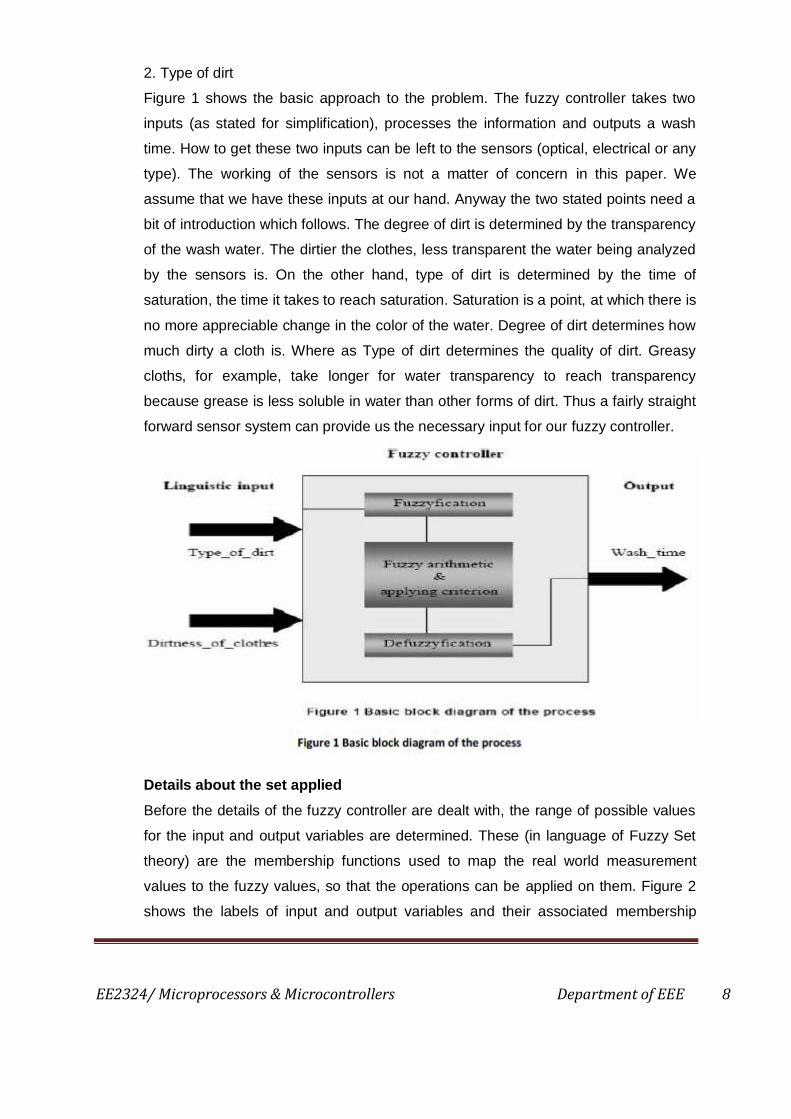
Figure 1 shows the basic approach to the problem. The fuzzy controller takes two
inputs (as stated for simplification), processes the information and outputs a wash
time. How to get these two inputs can be left to the sensors (optical, electrical or any
type). The working of the sensors is not a matter of concern in this paper. We
assume that we have these inputs at our hand. Anyway the two stated points need a
bit of introduction which follows. The degree of dirt is determined by the transparency
of the wash water. The dirtier the clothes, less transparent the water being analyzed
by the sensors is. On the other hand, type of dirt is determined by the time of
saturation, the time it takes to reach saturation. Saturation is a point, at which there is
no more appreciable change in the color of the water. Degree of dirt determines how
much dirty a cloth is. Where as Type of dirt determines the quality of dirt. Greasy
cloths, for example, take longer for water transparency to reach transparency
because grease is less soluble in water than other forms of dirt. Thus a fairly straight
forward sensor system can provide us the necessary input for our fuzzy controller.
Details about the set applied
Before the details of the fuzzy controller are dealt with, the range of possible values
for the input and output variables are determined. These (in language of Fuzzy Set
theory) are the membership functions used to map the real world measurement
values to the fuzzy values, so that the operations can be applied on them. Figure 2
shows the labels of input and output variables and their associated membership

EE2324/ Microprocessors & Microcontrollers Department of EEE 9
functions. Values of the input variables degree_of_dirt and type_of_dirt are
normalized range -1 to 100) over the domain of optical sensor. The decision which
the fuzzy controller makes is derived from the rules which are stored in the database.
These are stored in a set of rules. Basically the rules are if-then statements that are
intuitive and easy to understand, since they are nothing but common English
statements. Rules used in this paper are derived from common sense, data taken
from typical home use, and experimentation in a controlled environment. The sets of
rules used here to derive the output are:
1. If dirtness_of_clothes is Large and type_of_dirt is Greasy then wash_time is
VeryLong;
2. If dirtness_of_clothes is Medium and type_of_dirt is Greasy then wash_time is
Long;
3. If dirtness_of_clothes is Small and type_of_dirt is Greasy then wash_time is Long;
4. If dirtness_of_clothes is Large and type_of_dirt is Medium then wash_time is Long;
5. If dirtness_of_clothes is Medium and type_of_dirt is Medium then wash_time is
Medium;
6. If dirtness_of_clothes is Small and type_of_dirt is Medium then wash_time is
Medium;
7. If dirtness_of_clothes is Large and type_of_dirt is NotGreasy then wash_time is
Medium;
8. If dirtness_of_clothes is Medium and type_of_dirt is NotGreasy then wash_time is
Short;
9. If dirtness_of_clothes is Small and type_of_dirt is NotGreasy then wash_time is
VeryShort
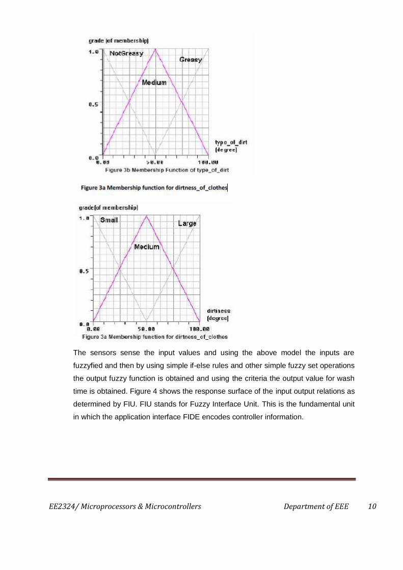
These rules have been shown as membership functions in figure 3.
EE2324/ Microprocessors & Microcontrollers Department of EEE 10
The sensors sense the input values and using the above model the inputs are
fuzzyfied and then by using simple if-else rules and other simple fuzzy set operations
the output fuzzy function is obtained and using the criteria the output value for wash
time is obtained. Figure 4 shows the response surface of the input output relations as
determined by FIU. FIU stands for Fuzzy Interface Unit. This is the fundamental unit
in which the application interface FIDE encodes controller information.

EE2324/ Microprocessors & Microcontrollers Department of EEE 11
The results (the above plot) shows the way the machine will response in different
conditions. For example, if we take type_of_dirt and dirtness value both to be 100,
the wash_time which the model output is equivalent to 60 mins. This is quite
convincing and appropriate.
Summary
By the use of fuzzy logic control we have been able to obtain a wash time for
different type of dirt and different degree of dirt. The conventional method required
the human interruption to decide upon what should be the wash time for different
cloths. In other words this situation analysis ability has been incorporated in the
machine which makes the machine much more automatic and represents the
decision taking power of the new arrangement. Though the analysis in this paper has
been very crude, but this clearly depicts the advantage of adding the fuzzy logic
controller in the conventional washing machine.
Future Directions
A more fully automatic washing machine is straightforward to design using fuzzy logic
technology. Moreover, the design process mimics human intuition, which adds to the
ease of development and future maintenance. Although this particular example
controls only the wash time of a washing machine, the design process can be
extended without undue complications to other control variables such as water level
and spin speed. The formulation and implementation of membership functions and
rules is similar to that shown for wash time.
EE2324/ Microprocessors & Microcontrollers Department of EEE 12
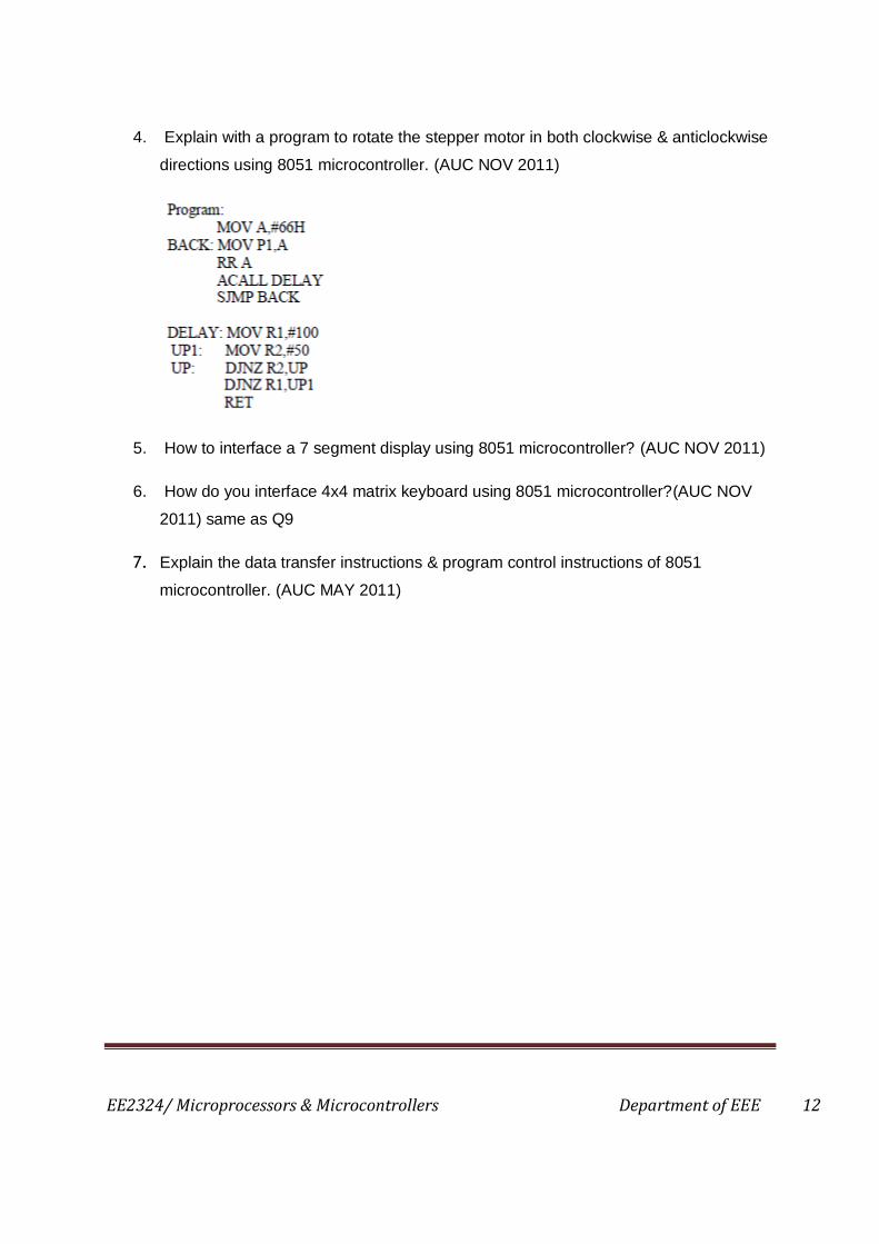
4. Explain with a program to rotate the stepper motor in both clockwise & anticlockwise
directions using 8051 microcontroller. (AUC NOV 2011)
5. How to interface a 7 segment display using 8051 microcontroller? (AUC NOV 2011)
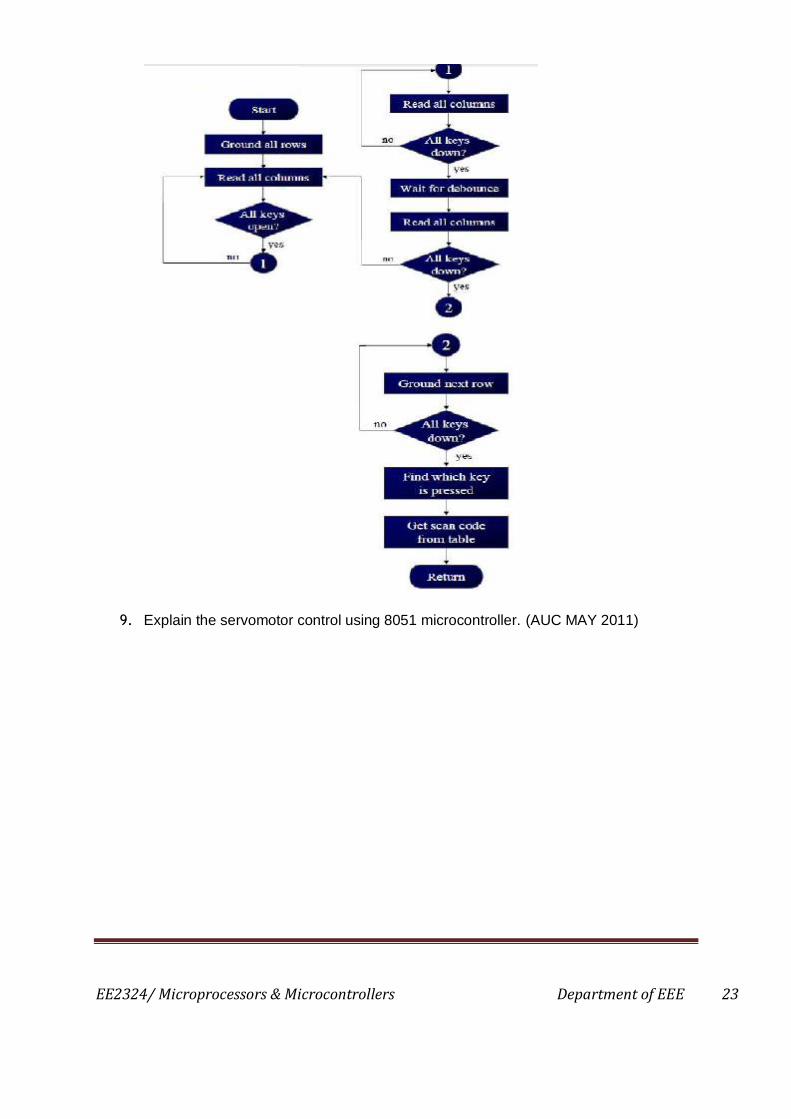
6. How do you interface 4x4 matrix keyboard using 8051 microcontroller?(AUC NOV
2011) same as Q9
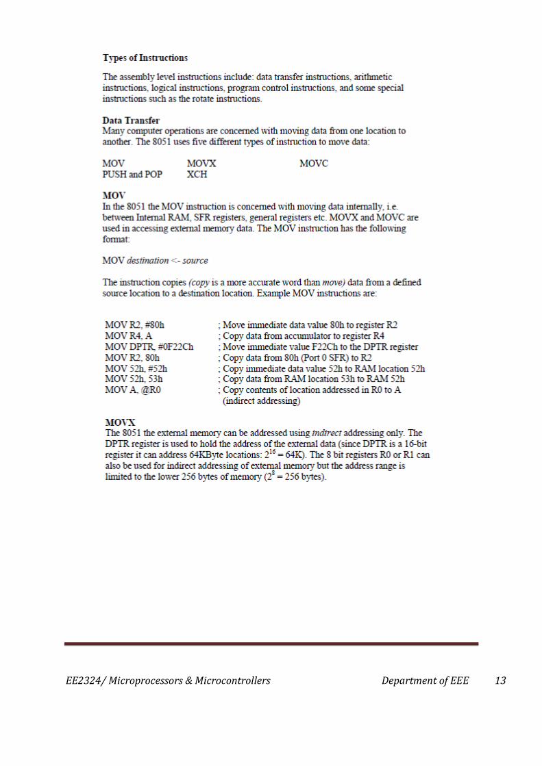
7. Explain the data transfer instructions & program control instructions of 8051
microcontroller. (AUC MAY 2011)
EE2324/ Microprocessors & Microcontrollers Department of EEE 13

EE2324/ Microprocessors & Microcontrollers Department of EEE 14

EE2324/ Microprocessors & Microcontrollers Department of EEE 15

EE2324/ Microprocessors & Microcontrollers Department of EEE 16

EE2324/ Microprocessors & Microcontrollers Department of EEE 17

EE2324/ Microprocessors & Microcontrollers Department of EEE 18

EE2324/ Microprocessors & Microcontrollers Department of EEE 19

EE2324/ Microprocessors & Microcontrollers Department of EEE 20

EE2324/ Microprocessors & Microcontrollers Department of EEE 21
8. Explain the interfacing of keyboard/ display with 8051 microcontroller. (AUC MAY
2011)

EE2324/ Microprocessors & Microcontrollers Department of EEE 22
EE2324/ Microprocessors & Microcontrollers Department of EEE 23
9. Explain the servomotor control using 8051 microcontroller. (AUC MAY 2011)