machining, assembly, and characterization of a meso-scale double
TRANSCRIPT
LAWRENCE
N AT I O N A L
LABORATORY
LIVERMORE
UCRL -1
Journal of Manufacturing Processes Vol. 6 No. 1 2004
Matthew J. Bono, Robin L. Hibbard
Machining, Assembly, and Characterization of a Meso-Scale Double Shell Target
-JRNL-152843-REV

This document was prepared as an account of work sponsored by an agency of the United States Government. Neither the United States Government nor the University of California nor any of their employees, makes any warranty, express or implied, or assumes any legal liability or responsibility for the accuracy, completeness, or usefulness of any information, apparatus, product, or process disclosed, or represents that its use would not infringe privately owned rights. Reference herein to any specific commercial product, process, or service by trade name, trademark, manufacturer, or otherwise, does not necessarily constitute or imply its endorsement, recommendation, or favoring by the United States Government or the University of California. The views and opinions of authors expressed herein do not necessarily state or reflect those of the United States Government or the University of California, and shall not be used for advertising or product endorsement purposes.

1
Machining, Assembly, and Characterization of a Meso-Scale Double Shell Target Matthew J. Bono, Robin L. Hibbard
Lawrence Livermore National Laboratory, Livermore, California 94550
Abstract Several issues related to the manufacture of precision meso-scale assemblies have been
identified as part of an effort to fabricate an assembly consisting of machined polymer hemispherical shells and machined aerogel. The assembly, a double shell laser target, is composed of concentric spherical layers that were machined on a lathe and then assembled. This production effort revealed several meso-scale manufacturing techniques that worked well, such as the machining of aerogel with cutting tools to form low density structures, and the development of an assembly manipulator that allows control of the assembly forces to within a few milliNewtons. Limitations on the use of vacuum chucks for meso-scale components were also identified. Many of the lessons learned in this effort are not specific to double shell targets and may be relevant to the production of other meso-scale devices.
Keywords Meso-scale machining, micromechanical machining, precision bonding, microassembly,
vacuum chucks, double shell target, diamond turning, aerogel
Introduction This paper evaluates and discusses some manufacturing techniques for fabricating
precision meso-scale assemblies related to micro-mechanical machining of components, part handling, fixturing, assembly, and bonding. The paper describes the manufacturing method used to fabricate a meso-scale assembly that will be used as part of an experiment in high energy density physics. The assembly, known as a double shell target, consists of two hollow, concentric spherical shells that are separated by a layer of aerogel, as illustrated in Figure 1. The inner shell has a diameter of approximately 592 microns. An aerogel structure holds the inner shell in place inside the outer shell, which has a diameter of 1254 microns and consists of two hemispherical shells (hemis) that are bonded together. The outer hemispherical shells and the aerogel structure that supports the inner capsule were fabricated using single-point diamond turning, and the components were mechanically assembled and bonded to produce the finished target. Each component was measured prior to assembly, and the completed target was radiographed to determine the concentricity between the two shells.
There has recently been a great deal of interest in the development of cutting tools and processes for micro-scale and meso-scale mechanical machining [1-6], but there has been relatively little documentation on the practicalities encountered in transforming these laboratory capabilities into production efforts to machine and assemble meso-scale engineered parts. This paper discusses some of the problems encountered and lessons learned regarding machining, fixturing, assembly, and bonding of this meso-scale artifact. Many of these issues are not specific to this particular fabrication effort but are applicable to the general manufacture of meso-scale components and assemblies and could benefit other manufacturing engineers faced with similar challenges.
The completed double shell target will be shot with a high power laser, causing it to implode and compress the material inside the inner capsule. The reaction of the compressed material will be diagnosed, and the data will be used to validate physics computer codes. As with all laser experiment targets, this double shell target has strict requirements on its geometry

2
and the precision with which it is fabricated. The target must be spherically symmetric, meaning the thickness of each shell should be uniform, the two shells should be concentric, and each shell should be smooth and free of defects. Tolerances on the absolute dimensions, sphericity, concentricity, and wall thickness uniformity are only a few microns. These requirements mean special care had to be taken in developing and executing a manufacturing plan.
Several previous researchers have successfully fabricated meso-scale double shell targets for high energy density physics experiments, and a variety of different manufacturing processes have been reported in the literature [7]. One popular method of producing outer hemispherical shells is to first create a hemispherical mandrel with an outer diameter equal to the desired inner diameter of the hemi [8-10]. The mandrel is then coated with the appropriate material, and the outer contour of the hemi is machined on its surface. After machining, the mandrel is leached away, leaving a freestanding hemi. With this method, the hemi can experience a dimensional change after the mandrel is removed. In another method, the outer shell is made in a single piece by coating a paraffin ball and subsequently removing the paraffin through a capillary [11]. However, the hole used to remove the wax must be plugged and creates a defect in the spherical shell. The inner capsule has been suspended inside the outer capsule in a variety of ways. Wires that suspend the inner capsule create an unacceptable nonuniformity [11]. The inner capsule can be supported by plastic films [8,9], but it is difficult to position the films well enough to control the concentricity of the two shells. Foams can also be used, but previous efforts that used foams to support the inner capsule required that the foams be backfilled prior to machining [9]. Furthermore, the foams experienced dimensional changes while leaching away the backfill material. Designs that involve hemis have been fabricated both with and without a step in the joint. The step creates an additional nonuniformity, but it also greatly facilitates alignment during assembly.
The manufacturing plan for these assemblies was designed to produce targets that match the characteristics desired by the physicists as closely as the available resources would allow. In addition, the manufacturing process is deterministic, and the components can be fabricated with a dimensional repeatability of 2 microns or better. A schematic diagram of the target design appears in Figure 1. The inner capsule is constructed of germanium-doped polymer and has an outer diameter of approximately 592 microns and a thickness of 38 microns. The inner capsule is supported inside the outer capsule by two machined hemispherical shells of thickness 206 microns that are composed of carbon resorcinol formaldehyde aerogel with a density of 0.1 g/cm3. The outer shell has an outer diameter of 1254 microns and a thickness of 125 microns. The outer shell is composed of bromine-doped polystyrene and consists of two hemispherical shells that mate at a step joint.

Polystyrene hemispherical shell
Polystyrene hemispherical shell
Inner capsule
Aerogel hemispherical shell
Aerogel hemispherical shell
Outer diameter = 1254 microns
Outer diameter = 592 microns
Outer diameter = 1004 microns
Polystyrene hemispherical shell
Polystyrene hemispherical shell
Inner capsule
Aerogel hemispherical shell
Aerogel hemispherical shell
Outer diameter = 1254 microns
Outer diameter = 592 microns
Outer diameter = 1004 microns
Figure 1. Exploded view of the double shell target
The following sections describe the construction of the components that make up the double shell target.
Inner Capsule Several inner capsules were manufactured by an external vendor, who also provided
metrology data on their dimensions and form. The manufacturer measured the diameter using an interferometer and measured the form using an AFM spheremapping tool. The capsules had reported ellipsoidal variations of up to approximately 1 micron. Upon receipt of the capsules, no additional machining was performed. It would have been preferable to measure the capsules again to verify the manufacturer’s data. However, the only metrology that was possible was to measure their outer diameters with a measuring microscope, and the uncertainty of ±3 microns in these measurements is much larger than the accuracy of the manufacturer’s interferometer measurements.
Aerogel Hemispherical Shells Two aerogel hemis support the inner capsule inside the outer shell. The physics of the
laser experiment for which the target will be used requires that the space between the two capsules contain as little mass as possible and be spherically symmetric. To provide a support structure of the smallest possible density, the inner capsule was held in place using low-density aerogel [12]. To maintain spherical symmetry, the support was made in the form of two identical hemispheres with an inner contour to fit the inner capsule and an outer diameter equal to the inner diameter of the outer shell. There are many possible methods of forming a component of a desired shape from aerogel [13], but precision machining with a diamond tool is a simple and relatively straightforward means of producing a hemisphere with adequate dimensional control. Aerogel materials have been made with densities as small as only a few mg/cm3, but aerogels with a density this small tend to crumble when machined. Therefore, an aerogel with a density of 0.1 g/cm3 was selected for the support hemis.
The hemis were machined on a Precitech Nanoform 200 diamond turning machine equipped with an air bearing spindle and a B-axis that allows the tool to rotate about its nose. All machining was performed with ambient temperature control of better than 0.5 degrees
3

Centigrade. The machine tool has a specified positional resolution of a few nanometers, and the absolute positional accuracy over the working volume of interest is estimated to be better than 0.2 microns. The workpieces were mounted in special holders that allow parts to be removed and reinstalled in the machine with a positional repeatability of approximately 0.3 microns. Single crystal diamond tools were used to machine the aerogel. These needle-like, single-point turning tools have a nose radius of 5.2 microns. To avoid crumbling or gouging the aerogel material, the feed was limited to 0.19 microns per revolution with a depth of cut of 2.5 microns and a spindle speed of 1600 rpm. With these cutting conditions, the aerogel could be deterministically machined to the desired size.
Each hemi was fabricated by first gluing a piece of the aerogel to a plastic arbor. The aerogel was rough machined to a cylindrical shape before machining a partial sphere onto the end, as illustrated in Figure 2a. The partial sphere was then broken off using a surgical blade and carefully inserted into a specially prepared vacuum chuck that consisted of a set of concentric vacuum channels that precisely matched the external contour of the machined aerogel (Figure 2b). The vacuum chuck was then placed in the diamond turning machine, and a workpiece coordinate system was established by touching the tool to the face of the vacuum chuck. The portion of the sphere extruding from the vacuum chuck was then faced down until only a hemisphere of aerogel remained. Next, the inner hemispherical cavity was machined into the aerogel (Figure 2c). The diameter of the cavity was machined to match the outer diameter of the inner capsule. Although the capsule was known to be slightly ellipsoidal, each cavity was machined in a nominally spherical shape. To verify that the completed aerogel hemi had the proper internal and external diameters, it was measured using an optical microscope equipped with precision stages with positional feedback. The aerogel hemi was then removed from the vacuum chuck using an assembly vacuum chuck.
a) b) c)
Vacuum chuck
Aerogel
Holder for diamond turning machine
Completed hemi
a) b) c)
Vacuum chuck
Aerogel
Holder for diamond turning machine
Completed hemi
Figure 2. Machining process for the aerogel hemis
Outer Ablator Hemispherical Shells The outer ablator shell consists of two polystyrene hemis that enclose the sub-assembly
made from the inner capsule and the aerogel hemis. The manufacturing process for the outer ablator hemis is illustrated in Figure 3. To fabricate each hemi, a piece of polystyrene was glued to a holder, placed in the diamond turning machine, and machined to a concentric cylinder (Figure 3a). The face of the resulting polystyrene cylinder was then diamond turned to a smooth finish. Next, the internal hemispherical cavity and the joint were machined (Figure 3b). The internal contour and the joint were machined with the same diamond tool used to machine the aerogel, and similar cutting conditions were used. For a roughing pass, the feed per revolution was generally 0.19 microns with a depth of cut of 2.5 microns. For a finishing pass, the feed per revolution was generally 0.038 microns with a depth of cut of 1.2 microns.
4
a) b) c) d) e)
Machined end
Nose chuck
Nose chuck
Holder for diamond turning machine
EpoxyCompleted hemi
Polystyrene
a) b) c) d) e)
Machined end
Nose chuck
Nose chuck
Holder for diamond turning machine
EpoxyCompleted hemi
Polystyrene
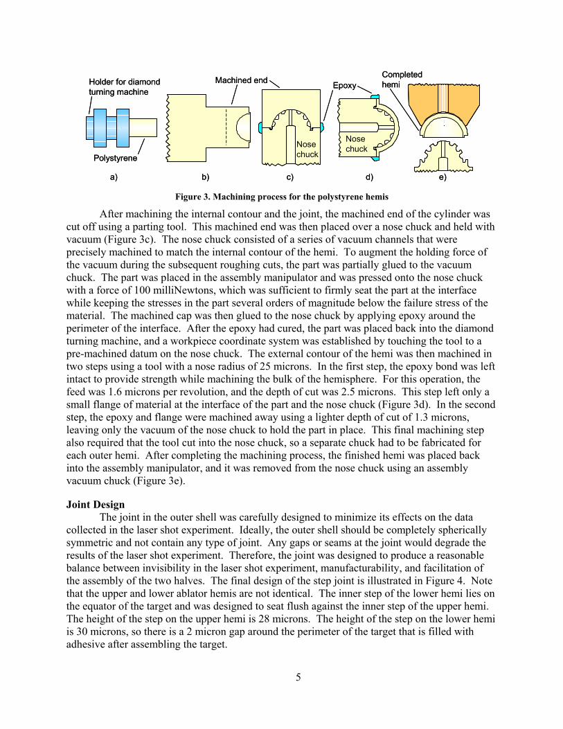
Figure 3. Machining process for the polystyrene hemis
After machining the internal contour and the joint, the machined end of the cylinder was cut off using a parting tool. This machined end was then placed over a nose chuck and held with vacuum (Figure 3c). The nose chuck consisted of a series of vacuum channels that were precisely machined to match the internal contour of the hemi. To augment the holding force of the vacuum during the subsequent roughing cuts, the part was partially glued to the vacuum chuck. The part was placed in the assembly manipulator and was pressed onto the nose chuck with a force of 100 milliNewtons, which was sufficient to firmly seat the part at the interface while keeping the stresses in the part several orders of magnitude below the failure stress of the material. The machined cap was then glued to the nose chuck by applying epoxy around the perimeter of the interface. After the epoxy had cured, the part was placed back into the diamond turning machine, and a workpiece coordinate system was established by touching the tool to a pre-machined datum on the nose chuck. The external contour of the hemi was then machined in two steps using a tool with a nose radius of 25 microns. In the first step, the epoxy bond was left intact to provide strength while machining the bulk of the hemisphere. For this operation, the feed was 1.6 microns per revolution, and the depth of cut was 2.5 microns. This step left only a small flange of material at the interface of the part and the nose chuck (Figure 3d). In the second step, the epoxy and flange were machined away using a lighter depth of cut of 1.3 microns, leaving only the vacuum of the nose chuck to hold the part in place. This final machining step also required that the tool cut into the nose chuck, so a separate chuck had to be fabricated for each outer hemi. After completing the machining process, the finished hemi was placed back into the assembly manipulator, and it was removed from the nose chuck using an assembly vacuum chuck (Figure 3e).
Joint Design The joint in the outer shell was carefully designed to minimize its effects on the data
collected in the laser shot experiment. Ideally, the outer shell should be completely spherically symmetric and not contain any type of joint. Any gaps or seams at the joint would degrade the results of the laser shot experiment. Therefore, the joint was designed to produce a reasonable balance between invisibility in the laser shot experiment, manufacturability, and facilitation of the assembly of the two halves. The final design of the step joint is illustrated in Figure 4. Note that the upper and lower ablator hemis are not identical. The inner step of the lower hemi lies on the equator of the target and was designed to seat flush against the inner step of the upper hemi. The height of the step on the upper hemi is 28 microns. The height of the step on the lower hemi is 30 microns, so there is a 2 micron gap around the perimeter of the target that is filled with adhesive after assembling the target.
5

28 um 30 um
70oLower hemi
Upper hemiCenterline of sphere
125 um
28 um 30 um
70oLower hemi
Upper hemiCenterline of sphere
125 um
Figure 4. Joint between the two outer ablator hemis
Assembly Process The components were assembled using a specially designed manipulator that incorporates
a force sensor to allow the operator to determine when mating components have made contact, and to control the assembly forces to within a few milliNewtons. A schematic diagram of this assembly manipulator is illustrated in Figure 5.
Vacuum hose
Vacuum hose
Rec
tang
ular
sl
ider
bar
Air bearing carriage
Mic
rom
eter
dr
iven
z s
tage
x, y, z stages
θzspindle
Upper kinematic mount
Lower kinematic mount
Force transducer
Spring
Cord
Bracket
140 kPa air supply
z
yx
Vacuum hose
Vacuum hose
Rec
tang
ular
sl
ider
bar
Air bearing carriage
Mic
rom
eter
dr
iven
z s
tage
x, y, z stages
θzspindle
Upper kinematic mount
Lower kinematic mount
Force transducer
Spring
Cord
Bracket
140 kPa air supply
z
yx
z
yx
Figure 5. Schematic diagram of assembly manipulator
The assembly manipulator consists of two sets of actuators that allow the mating components to be aligned and then assembled. The same holders used to mount the parts in the diamond turning machine can also be loaded into kinematic mounts on the assembly manipulator. One of the mating components to be assembled is installed into the kinematic mount on the lower set of actuators, which consists of a set of stages that are driven by manual micrometers with a resolution of 1 micron. This set of stages allows the part to be oriented in the x- and y-directions, and two perpendicular microscopes allow the operator to visually determine
6

when the mating parts are aligned. The lower set of actuators also incorporates a dovetail stage to allow coarse motion in the z-direction, and a spindle allows the lower component to be rotated in θz.
The other mating component is installed in the kinematic mount on the upper set of actuators. This set of actuators provides fine motion in the z-direction to assemble the components. This set of actuators has been designed to provide control over the assembly forces to within a few milliNewtons by providing controlled compliance in the z-direction. The upper kinematic holder is attached to one end of a rectangular air bearing with a slider bar that is free to move in the z-direction but is constrained in each of the other five degrees of freedom. A strain gauge force transducer with a capacity of 2.5 N is attached to the opposite end of the air bearing slider bar. Because the air bearing provides nearly frictionless motion, the force measured by the transducer is nearly the same as the force acting in the z-direction on the component mounted to the lower end of the slider bar. Note that the cord extending from the force transducer and the vacuum hose attached to the upper kinematic mount impose external forces that cause the force measured by the transducer to differ from the force on the components by up to a few milliNewtons. For a typical assembly force of 150 milliNewtons, the force transducer provides an uncertainty of better than 7%. A spring with a stiffness of 175 N/m connects the opposite end of the force transducer to a stage that is driven by a manual micrometer.
To assemble the components, the lower actuators are first adjusted to align them properly, and then the components are brought together by turning the micrometer on the upper set of actuators. When the components make contact with each other, the force transducer measures the force between them in the z-direction. To increase the assembly force, the operator turns the micrometer further, which compresses the spring. Because the springrate is 175 µN/µm, the operator has precise control over the assembly force.
The assembly steps for the target are illustrated in Figure 6. First, the lower outer hemi was placed into the manipulator (Figure 6a). Next, one of the aerogel hemis was inserted (Figure 6b), and then the inner capsule was placed into the contour in the aerogel (Figure 6c). The other aerogel hemi was then placed on top of the inner capsule (Figure 6d). Finally, the upper outer hemi was placed on top to complete the assembly (Figure 6e). The assembly vacuum chuck was used to press the outer hemis together with a force of 150 milliNewtons while they were bonded. An assembly force of 150 milliNewtons was selected, because it is sufficient to firmly seat the components, and a finite element analysis indicated that this force subjects the spherical shell to a maximum stress on the order of 105 to 106 Pa, which is an order of magnitude below the estimated failure stress of the material.
a) b) c) d) e)a) b) c) d) e) Figure 6. Assembly process
7

To join the two outer hemis, the joint was glued by applying three spots of cyanoacrylate adhesive in 120 degree intervals by hand using a single camel hair on the end of a stick. A droplet of the adhesive on the camel hair has a diameter of almost 100 microns, so the volume of the droplet is approximately 0.5 nanoliters. The gap in the joint also has a volume of 0.5 nanoliters, so excess adhesive was usually applied. The adhesive wicked into the 2 micron gap of the joint and cured to form a secure bond. The excess adhesive spread to a thickness that was too small to measure with the available equipment, and it was simply left on the surface of the target. A picture of the completed target appears in Figure 7.
1 millimeter
Figure 7. Completed double shell target in a vacuum chuck
Characterization of the Assembled Target A total of six double shell targets were manufactured in this effort. Each target has strict
requirements on its geometry and must be spherically symmetric, meaning the thickness of each shell should be uniform, the two shells should be concentric, and each shell should be smooth and free of defects. Tolerances on the absolute dimensions, concentricity, and wall thickness are only a few microns. To ensure that the targets met the requirements, the target components were measured prior to assembly. In addition, two radiographs were taken of each assembled target to determine the concentricity between the inner and outer shells.
Radiographs of one of the completed targets appear in Figure 8. One radiograph was taken normal to the joint, and the other was taken in the plane of the joint. The radiographs reveal a radial concentricity error of 2 microns, based on centers calculated from the outer diameter of the inner capsule and the inner diameter of the outer shell. This misalignment lies within the specified tolerance of 5 microns, and it correlates to a concentricity error of ∆r/r = 0.3%.
8

Figure 8. Radiographs of the completed target taken normal to the joint (left) and parallel to the joint (right)
2
2222
6
The metrology data for each of the six targets is summarized in Table 1. The values in the table represent the deviations of the measured values from the design values, in units of microns.
AssemblyInner Diam [µm]
Wall Thickness
[µm]
Step in Joint [µm]
Outer Diam [µm]
Inner Diam [µm]
Outer Diam [µm]
Concentricity [µm]
1004 125 upper=28 lower=30 1254
OD of inner
capsule 1004 0
Upper 0 1 0 0 0Lower 0 1 0 1 0 0Upper 0 0 0 0 1 0Lower 1 -1 0 0 1 0Upper 0 1 0 0 0Lower 0 1 1 1 0Upper 0 1 1 0 0Lower 1 0 0 1 0Upper 0 0 0 1 1 0Lower 0 0 0 1 1 0Upper 0 1 0 1 1 0Lower 0 0 0 1 1 0
Deviations from Design Values [µm]
Component:
Target 1
Target 2
Target 3
1
1
Design Value:
Dimension:
Target 4
Target 5
Target 6
Outer Hemis Aerogel Hemis
target was not radiographed
2
2
Table 1. Summary of metrology data for the six targets
With the exception of the concentricity, each measurement was made on a measuring microscope and has an uncertainty of ±1 micron. Note that every component was fabricated with an accuracy of 1 to 2 microns. With the exception of Target 2, each of the targets that was radiographed is concentric to within 2 microns or better. This particular target was only the second one assembled, and the cause of the larger eccentricity appears to have been worked out for the subsequent assemblies. Therefore, the current method of supporting the inner capsule with machined hemis of aerogel appears to be an adequate means of obtaining concentricity.
Discussion This effort identified several meso-scale manufacturing techniques that worked well, and
it also revealed some practicalities that could benefit from further development. The greatest
9

10
challenge in machining the components was the fixturing of the parts in the precision lathe. Carefully crafted vacuum chucks proved to be adequate for making the internal and external contours on the polystyrene and aerogel workpiece materials. The theoretically achievable torque that a spherical vacuum chuck can support is proportional to the radius to the third power (radius3), so at the meso-scale, vacuum alone often will not provide sufficient grip. Therefore, the vacuum was augmented by epoxying parts to the nose chuck for the roughing cuts. These vacuum chucks provided the necessary accuracy, held the parts securely enough to withstand the cutting forces, and allowed the parts to be released without damaging them. The aerogel material was found to machine with adequate dimensional accuracy when depths of cut on the order of a micron were used. This effort also revealed the necessity of controlling the assembly forces. Initial assembly efforts used an assembly manipulator in which the operator controlled the displacement of the components but had no control over the forces. With this device, an error of only a few microns would cause the outer hemis to fracture. Several components were destroyed before a new assembly manipulator was designed with axial compliance and a force transducer to give the operator control over the assembly forces to within a few milliNewtons.
One of the greatest challenges encountered in the fabrication of these targets was the bonding of the outer hemis. This step of the manufacturing process received little attention and requires further development. This target was designed to be bonded with an adhesive, because they are readily available and initially appeared to be simple to implement. However, most adhesives have been designed for macroscopic bonding processes and pose problems when used for meso-scale applications. The primary purpose of the adhesive is to bond the hemis with sufficient strength to withstand handling of the targets. Only minor traces of adhesive in and around the joint are acceptable, because large quantities would degrade the physics intent of the target. Furthermore, the adhesive must wick into the joint to obtain a good bond, but it must not wick past the step in the joint and into the aerogel, because the added full-density material between the shells would have adverse effects on the performance of the target.
The first target constructed was fabricated from as-cast polystyrene, which had an adverse reaction to the cyanoacrylate and formed a pattern of small cracks on the outer surface. In an effort to avoid this crazing, a UV curing adhesive was tested. Unfortunately, the UV adhesive was prone to oxygen inhibition, so its surface remained tacky and would not cure fully. Because the thickness of the adhesive layer in the joint is only 2 microns, a one micron film of uncured adhesive would not be acceptable. An epoxy and a polyvinyl acetate adhesive were also considered, but it was feared that the long cure times could allow the adhesive to wick into the aerogel. The wicking is not a concern with cyanoacrylate, because it cures almost instantly. Therefore, instead of searching for a different adhesive, the workpiece material was modified to make it more compatible with cyanoacrylate. For the final production, the polystyrene was heat treated to remove the residual stresses before it was machined. This heat treated material did not experience crazing upon contact with the cyanoacrylate and was used for the final targets.
Another significant problem was encountered with the application of the adhesive. In this study, the adhesive was applied to the joint by hand by placing a droplet on the end of a hair. It is difficult for human fingers to achieve the 2 micron positional accuracy required to place the hair directly over the joint. In addition, it is difficult to control the volume of adhesive applied to the joint, and the volume of adhesive on the hair may have been several times larger than the volume of the joint. Both of these factors contributed to excess adhesive being applied that covered an exterior portion of the target near the joint. Several avenues for applying the adhesive more accurately are currently being explored, including a pneumatic dispenser coupled
11
with a precision manipulator, and an alternative manufacturing method that involves machining away excess adhesive during the finishing cuts.
Another area that requires significant improvement is the characterization of the assembled targets. The microscope measurements and radiographs used in this effort do not provide all of the desired information about the targets, such as the wall thickness uniformity, the form of each of the shell surfaces, and the form assumed by the adhesive after wicking into the step joint, to name but a few. There is a critical need for improved metrology and characterization tools that can provide this type of information. These tools would benefit not only the manufacture of laser targets, but all meso-scale manufacturing efforts in general.
Conclusions This paper evaluates and discusses manufacturing techniques used to fabricate a precision
meso-scale assembly consisting of machined polymer hemispherical shells and machined aerogel. Issues have been identified relating to micro-mechanical machining, part handling, fixturing, assembly, and bonding. This effort revealed several techniques that worked well and others that require further development. Using a depth of cut on the order of a micron, aerogel can be deterministically machined with cutting tools to form low density meso-scale structures. Vacuum chucks provide an excellent means of fixturing parts to machine both internal and external contours on meso-scale components. In cases in which the tool exerts a large force or torque on the part, the holding force of the vacuum can be augmented by gluing the workpiece to a sacrificial vacuum chuck. The assembly of meso-scale components is complicated by part alignment and the fragility of the parts. This effort required an assembly fixture in which the operator controlled the assembly forces to within a few milliNewtons. A fixture in which the operator controlled the relative displacement of the components proved to be insufficient. The bonding of the components was one of the crucial steps in the manufacturing plan, and of the adhesives tested, cyanoacrylate performed best. This effort would have benefited from an ability to control the amount of adhesive dispensed with picoliter resolution and place the adhesive on the part with micron-level accuracy. Many of these issues are not specific to this particular fabrication effort but are applicable to the general manufacture of meso-scale components and assemblies.
Acknowledgements This effort would not have been possible without the skill, innovation, and
resourcefulness of the machinists, Don Bennett and Carlos Castro. This work was performed under the auspices of the U.S. Department of Energy by the Lawrence Livermore National Laboratory under Contract No. W-7405-Eng-48.
References 1. D.P. Adams, M.J. Vasile, G. Benavides, and A.N. Campbell, “Micromilling of metal alloys
with focused ion beam-fabricated tools,” Precision Engineering (v25, 2001), pp107-113. 2. D.P. Adams, M.J. Vasile, and A.S.M. Krishnan, “Microgrooving and microthreading tools
for fabricating curvilinear features,” Precision Engineering (v24, 2000), pp347-356. 3. M. Weck, S. Fischer, and M. Vos, “Fabrication of microcomponents using ultraprecision
machine tools,” Nanotechnology (v8, 1997), pp145-148. 4. M.J. Vasile, C.R. Friedrich, B. Kikkeri, and R. McElhannon, “Micrometer-scale machining:
tool fabrication and initial results,” Precision Engineering (v19, 1996), pp180-186.

12
5. Z.J. Yuan, M. Zhou, and S. Dong, “Effect of diamond tool sharpness on minimum cutting thickness and cutting surface integrity in ultraprecision machining,” Journal of Materials Processing Technology (v62, 1996), pp327-330.
6. N. Ikawa, S. Shimada, and H. Tanaka, “Minimum thickness of cut in micromachining,” Nanotechnology (v3, 1992), pp6-9.
7. K.R. Schultz, J.L. Kaae, W.J. Miller, D.A. Steinman, and R.B. Stephens, “Status of inertial fusion target fabrication in the USA,” Fusion Engineering and Design (v44, 1999), pp441-448.
8. C.W. Hatcher, L.E. Lorensen, and B.W. Weinstein, “Double-shell inertial confinement fusion target fabrication,” Journal of Vacuum Science & Technology (v18, n3, 1981), pp1187-1190.
9. J.R. Duke, N.E. Elliott, J.E. Moore, V.M. Gomez, R. Manzanares, G. Rivera, R. Watt, W.S. Varnum, and P.L. Gobby, “The Fabrication of Double Shell Targets for Nova,” Fusion Technology (V35, n2, 1999), pp90-94.
10. A. Nobile, J.J. Bartos, R.D. Day, N.D. Delamater, J.E. Elliott, N.E. Elliott, V.M. Gomez, D.J. Hatch, G.A. Kyrala, R. Manzanares, T.H. Pierce, D.L. Sandoval, D.W. Schmidt, and W.P. Steckle, “Recent Developments in Fabrication of Double Shell Targets for Experiments at the OMEGA Laser,” 15th Target Fabrication Specialists Meeting, June 1-5, 2003, Gleneden Beach, OR.
11. T. Norimatsu, A. Furusawa, M. Yoshida, Y. Izawa, and C. Yamanaka, “Fabrication of double shell targets for laser fusion,” Journal of Vacuum Science & Technology (v18, n3, 1981), pp1288-1289.
12. R.W. Pekala, “Organic aerogels from the polycondensation of resorcinol with formaldehyde,” Journal of Materials Science (v24, n9, 1989), pp3221-3227.
13. S.M. Lambert, G.E. Overturf, G. Wilemski, S.A. Letts, D. SchroenCarey, and R.C. Cook, “Fabrication of low-density foam shells from resorcinol-formaldehyde aerogel,” Journal of Applied Polymer Science (v65, n11, 1997), pp.2111-2122.
Authors’ Biographies Matthew Bono is a mechanical engineer at Lawrence Livermore National Laboratory.
He received his BS from the University of Virginia and his MS and PhD from the University of Michigan. His research interests are precision engineering, machining, micro-scale and meso-scale manufacturing, and metrology.
Robin Hibbard is a project manager and precision engineer in the Precision Systems and Manufacturing Group at Lawrence Livermore National Laboratory. He received his BS from California Polytechnic San Luis Obispo and his MS and PhD from the University of California Davis. His research interests are precision engineering, systems engineering, metrology, and meso-scale manufacturing.