m5/ piping/ non ibr/ 2459 dated 15.12.2012 corrigendum...
TRANSCRIPT

1
M5/ PIPING/ NON‐IBR/ 2459 dated 15.12.2012
Corrigendum –I
No. Tender Enquiry No. M5/ PIPING/ NON‐IBR/Advt. No. 91/ 2220 dated 16‐11‐2012 against our above tender enquiry Corrigendum –I published in the following amendment are being issued:
TABLE‐A
Sl. No.
Page No. / Clause No. (Reference: Webcast Tender Document)
FOR READ AS
1. Section‐VI/Clause No. 1.2.5, Page‐17
SPM will make available the following items free of cost to the successful Tenderer:
Power, Water required for testing and commissioning.
However, successful Tenderer shall send prior intimation to the SPM indicating the details of above utility requirement for testing and commissioning
SPM will make available the following items free of cost to the successful Tenderer:
Power & Water required for erection, testing and commissioning.
However, successful Tenderer shall send prior intimation to the SPM indicating the details of above utility requirement for erection, testing and commissioning.
2. Section‐VII/Clause No. 8.00.00, Page‐24
Nil DRAWINGS/DATA/DOCUMENTS TO BE SUBMITTED BY THE SUCCESSFUL TENDERER
3. Section‐VII/Clause No.4.02.02, Page‐30
Installation of Flanged Joints For technical requirements refer to Mechanical Standard No. A4 034.225.02
Installation of Flanged Joints For technical requirements refer to Mechanical Standard No. A4.034.227.3
4. Section‐VII/Clause No. 4.03.00, Page‐32
4.03.00 INSPECTION AND TESTING 4.03.23 INSPECTION AND TESTING
5. Section‐VII/Clause No. 4.04.00, Page‐32
4.04.00 SCHEDULE OF QUANTITY 4.03.24 SCHEDULE OF QUANTITY
6. Section‐VII/Clause No. 4.03.00, Page‐32
4.03.00 INSPECTION AND TESTING 4.03.00 TECHNICAL REQUIREMENT FOR INSULATION WORK
A. GENERAL INFORMATION
Note: For Clause No. 4.03.01 to 4.03.22 Please

2
Read from attached Annexure‐4
7. Section‐VII/Clause No. 7.00.00/C, Page‐34
C. Schedules
1 Schedule of Special Materials
2. Spring Hanger Schedule
3. Flushing/Cleaning/blowing/pickling/
Passivating schedule.
4. Schedule of local access platforms (Piping & valves)
C. Schedules
1 Schedule of Special Materials
2. Schedule of local access platforms
(Piping & valves)
8. Section‐VII/Clause No. 8.00.00, Page‐34
Nil DRAWINGS, DATA & DOCUMENTS TO BE SUBMITTED BY THE SUCCESSFUL TENDERER 1. Spring Hanger Schedule. 2. Flushing/Cleaning/blowing/pickling/ passivating schedule. 3. Overall project Schedule in form of bar chart. 4. Material Test Certificates. 5. Dimensional drawing of pipes, valves, Fittings, Flanges, Gaskets etc.
9. Section‐VIII/Appendix‐C, Sl. No.‐4, Page‐42
Sl. No.
Spec. Code & Type
Description Valve Size, mm NB
Quantity
4 Control valve (FOR SULPHURIC ACID AND SODIUM HYDROXIDE LINE)
80 2
Sl. No.
Spec. Code & Type
Description Valve Size, mm NB
Quantit
4 Control valve (FOR SULPHURIC ACID AND SODIUM HYDROXIDE LINE)
Press. Class ‐PN10 MOC For H2SO4 Control Valve : Body‐ Carbon Steel, Internals‐ SS 13% Gr. MOC For NaOH Control Valve : Body‐ AISI 316/CF8M, Internals‐ SS 13% Gr.
80 2
10. Section‐VII/Appendix‐D, DWG. NO. A4.034.226.20.2/ 3.2.1, Page‐46
5O NB & above – use Unions.
5O NB & below – use Unions.
11. Section‐VII, Appendix D, Page‐48/1.1.1
150 NB & Below ‐ Either of the following :
a) ASTM A53 Grade A or B, Seamless or ERW carbon steel
b) ASTM A106 Grade A or B, Seamless or ERW carbon steel
150 NB & Below ‐ Either of the following :
a) ASTM A53 Grade A or B, ERW carbon steel
b) ASTM A106 Grade A or B, ERW carbon steel

3
Chief Purchase & Stores Officer
12. Section‐VII, Appendix D, Page‐53
4.1.1 For ‘Run’ sizes 50 NB & below ‐ As per para 1.1 of DCPL Std. .034.226.38.
4.1.2.1 Method of connection ‐ As per para 1.2.1 of DCPL Std. .034.226.38.
4.1.2.2 Method of welding attachment
a) For Branches without Reinforcement ‐ As per DCPL Std. .034.201.21.
b) For Branches with Reinforcement ‐ As per DCPL Std. .034.201.9.
4.1.1 For ‘Run’ sizes 50 NB & below ‐ As per para 1.1 of DCPL Std. A4.034.226.38.
4.1.2.1 Method of connection ‐ As per para 1.2.1 of DCPL Std. A4.034.226.38.
4.1.2.2 Method of welding attachment
a) For Branches without Reinforcement ‐ As per DCPL Std. A4.034.201.21.
b) For Branches with Reinforcement ‐ As per DCPL Std. A4.034.201.9.
13. Section‐VII, Appendix D, Page‐56
3.1.1.1 Method of Welding Attachment ‐ As per DCPL Mech. Std. Drg. No. A.034.203.02
3.1.1.1 Method of Welding Attachment ‐ As per DCPL Mech. Std. Drg. No. A4.034.203.02
14. Section‐VII/ Appendix‐D, Page‐112 to 119
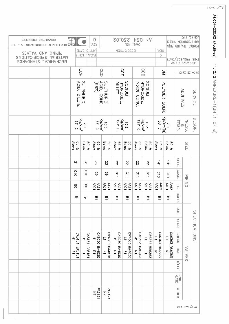
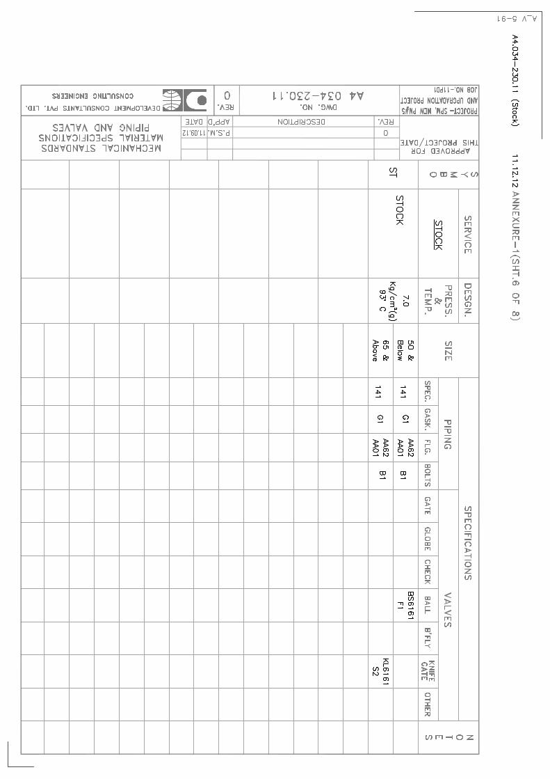
Page not prominent of DWG. NO. A4.034‐230.02,03,07,08,10,11,12,13
Please Read from attached Annexure‐1
15. Section‐XI/Part‐A(sheet‐4 of 4), Page‐147
Price Schedule Part‐A Sheet ‐ 4 of 4 , Page 147 Please Read from attached Annexure‐2
16. Section‐XI/Part‐B(sheet‐4 of 4), Page‐151
Price Schedule Part‐B Sheet ‐ 4 of 4 , Page 151 Please Read from attached Annexure‐3
17. T.E. No. M5/Piping /NON‐ IBR/Advt. No. 91/ 2220 Dated 16.11.2012
Closing date and time for receipt of tender 10:30 Hrs. On 08.01.2013
Closing date and time for receipt of tender 10:30 Hrs. On 15.01.2013
Opening date and time of tender 11:00 Hrs. On 08.01.2013
Opening date and time of tender 11:00 Hrs. On 15.01.2013

ANNEXURE‐1


ANNEXURE‐2

ANNEXURE-2
PART – A (Sheet-4 of 4)
Quoted Price of Supply Items (FOR SPM, Hoshangabad)
SL. NO.
SPECIFICATION CODE NO.
SUPPLY ITEM
DETAILED SPECIFICATION
SIZE (mm NB)
QUANTITY (METERS/NOS)
UNIT RATE (Rs.)
AMOUNT (Rs.)
72 15 2 NOS
73
BS6363F1
BALL VALVE Ref. Sheet 1 of Appendix‐C 40 2 NOS
74 15 2 NOS
75
BA4030F1
BALL VALVE Ref. Sheet 2 of Appendix‐C
40 2 NOS
76 CONTROL VALVE
Ref. Sheet 2 of Appendix‐C
80 2 NOS
77 Supply of Thermal Insulation (Unit of Measurement – Meter. Measured along the C.L. of insulated pipe line)
a) 50 960 METERS
b)
INSULATION ON PIPES
Ref. of Appendix‐F 65(Consideri
ng 20NB Steam
Tracing line)
42 METERS
c) 50 60 NOS
d)
90o Elbow
65 15 NOS
78 Supply of supports, Hangers & Brackets (Quote per Tonne. Quantity shown is indicative only. Actual quantity shall be as measured during erection)
a) Miscellaneous Pipe Supports
Ref. Cl. No. 2.01.06 of Section‐VII of this Specification
‐ 1.0 MT
79 Packing & Forwarding charges
80 Freight charges including Unloading at site
81 Taxes & Duties as applicable
82 Total Price of Supply Items (1 to 81) in Figures 83 Total Price of Supply Items (1 to 81) in Words

ANNEXURE‐3

Note:‐ 1. Cost of fabrication and erection of the above items should be inclusive of cost of sandblasting, cleaning
and painting as per requirement of the specification. 2. The method of evaluation of L1 criteria for awarding the Contract shall be on consolidated offer by the
bidder and will be decided taking into consideration of total offered price including Part (A+B) as above.
Bidder’s Signature_________________________
ANNEXURE-3
PART – B (Sheet-4 of 4)
Quoted Price of Services (FOR SPM, Hoshangabad) SL. NO.
SPECIFICATION CODE NO.
ITEM DETAILED SPECIFICATION
SIZE (mm NB)
QUANTITY (METERS/NOS)
UNIT RATE (Rs.)
AMOUNT (Rs.)
74 15 2 NOS
75
BA4030F1
BALL VALVE
Ref. Sheet 2 of Appendix‐C
40 2 NOS
76 CONTROL VALVE
Ref. Sheet 2 of Appendix‐C
80 2 NOS
77 Application of Thermal Insulation (Unit of Measurement – Meter. Measured along the C.L. of insulated pipe line)
a) 50 960 METERS
b)
INSULATION ON PIPES
Ref. of Appendix‐F 65(Consideri
ng 20NB Steam
Tracing line)
42 METERS
c) 50 60 NOS
d) 90o Elbow
65 15 NOS
78 Installation of Buried Steel Pipes (Unit of Measurement‐ Meter. Measured along the C.L. of installed pipe line)
a) Excavation For 250 mm NB Pipe
Suitable for 300.0 M long Pipe
b) Backfilling For 250 mm NB Pipe
Suitable for 300.0 M long
Pipe
c) Surface Protection
Ref. Cl. No. 4.02.06 of Section‐VII of this Specification
For 250 mm NB Pipe
Suitable for 300.0 M long
Pipe
79 Fabrication of supports, Hangers & Brackets (Quote per Tonne. Quantity shown is indicative only. Actual quantity shall be as measured during erection)
a) Miscellaneous Pipe Supports
Ref. Cl. No. 2.01.06 of Section‐VII of this Specification
‐ 1.0 MT
80 Taxes & Duties as applicable
81 Total Price of Services (1 to 80) in Figures 82 Total Price of Services (1 to 80) in Words
TOTAL ERECTED & COMMISSIONED COST OF PIPING (PART‐A + PART‐B) in Figures TOTAL ERECTED& COMMISSIONED COST OF PIPING (PART‐A + PART‐B) in Words

ANNEXURE‐4

4.03.01 Hydrostatic tests of piping to be insulated shall be completed before insulation is applied. All supports and hangers shall be in position and correctly adjusted. Protrusions through insulations which themselves do not require insulation, such as pipe clamps, supports of small piping, instrument take‐offs etc., shall be covered to the same thickness as the adjacent insulation and except at hanger rods.
4.03.02 Surfaces to be insulated shall be cleaned of all dirt, oil, loose scale etc. All insulation shall be supplied at ambient temperature and both the metal surface and insulation material shall be dry prior to application of insulation.
4.03.03 Except otherwise indicated in the Project drawings, a minimum of 25 mm clearance shall be maintained between the outside surface of insulation and other adjacent equipment or structural members.
4.03.04 Expansion joints shall be provided as required as per B.S. Code CP 3005 and shall be filled with loose insulation material. 4.03.05 Insulation shall be provided for all piping containing fluids or vapours for which it is necessary to (a) conserve heat (b) maintain process temperature (c) provided personnel protection. 4.03.06 Unless otherwise indicated equipments and piping having surface temperature above 60OC and not requiring insulation for conservation or other process requirements shall be insulated for personnel protection, up to a height of 2500 mm from finished grade or operating platform level and adjacent to and within 600 mm of a walkway, platform or ladder.
4.03.07 Name plates and data plates shall not be insulated. Insulation around markings or nameplates shall be sealed to be weather‐proof.
4.03.08 Drain and vent lines in insulated lines downstream of a first block valve shall not be insulated. 4.03.09 Manholes and hand holes shall not be insulated.
Flanges and flanged valves on lines operating below 200OC with the exception of steam lines shall not be insulated. Insulation of pipe shall terminate at such distance from a flanged joint as will allow withdrawal of bolts without disturbing insulation.
4.03.10 Inspection plug shall be provided on pipes to assess corrosion.
B. INSULATION SUPPORTS
4.03.11 Insulation supports for pipes shall be generally as per Mechanical Standard Dwg. No. A4. 001‐013 and the relevant dwg. For insulation application as attached herewith.
4.03.12 Suitable supports in form of rings, lugs, or pins shall be used to supports insulation on pipes. Insulation of vertical piping shall be supported by support rings.
ANNEXURE-4 (SHT. 1 OF 3)

4.03.13 Support rings shall be not less than 3 mm thick. However, the insulation contractor shall provide the supports wherever any additional support is required.
4.03.14 Except otherwise noted in the attached drawings, spacing of studs, clips of pins used to support insulation shall be approximately 600 mm centres for Blanket insulation and one per block for block insulation. Split pins, if used, shall be spread, bent over and embedded into the insulation.
C. HOT INSULATION
Insulation application procedure shall be as described herein under.
4.03.15 Application on Piping :
1) Mechanical Standard Dwg. No. A4.001‐003, shall generally be followed for application of Insulation on piping.
2) Jaketing shall be applied with longitudinal and circumferential laps of 50 mm secured by G.I. Bands spaced 300 mm centres or by self‐tapping screws at 150 mm centres. Longitudinal laps on horizontal pipes shall be arranged 30O below the horizontal centre‐line to shed water.
3) If insulation thickness exceeds 75 mm, the insulation shall be applied multiple layers. The multiple layers shall be so applied that the butt joints of one layer do not coincide with those of the other layer. At the joint of each layer of insulation, loose insulating material shall be packed firmly.
4.03.16 Application on Flanges & Valves : Removable covers shall be provided over all flanges and valves, wherever they are
required to be insulated. The insulation shall be performed as per the details furnished in Mechanical Standard Dwg. No. A4.001-004.
D. MATERIAL
4.03.17 Insulating material shall be mineral wool having density – 120 kg/m3 (in mattress form).
4.03.18 Weather‐proofing jacket shall be of Aluminium sheet, jacket thickness for pipes and vessels shall be as follows :
For pipes having dia. over
iinsulation less than 350 mm ‐ 24 Gauge (0.56 mm)
For pipes having dia, more
than 350 mm over insulation ‐ 22 Gauge (0.71 mm)
ANNEXURE-4 (SHT. 2 OF 3)

4.03.19 Wire netting shall be type H2 galvanized per any International Standard and sewing wire shall be of GI per any International Standard.
4.03.20 elf tapping cadmium plated screws shall be used.
4.03.21 Flats/ stays of MS to be used wherever required.
4.03.22 Metallic joints shall be sealed by sealing materials to protect insulation from outside moisture.
ANNEXURE-4 (SHT. 3 OF 3)