lte tutorial
TRANSCRIPT
1
3G Long-Term Evolution (LTE)
Farooq Khan
Samsung Telecom R&D CenterRichardson, Texas
September 25, 2006
2
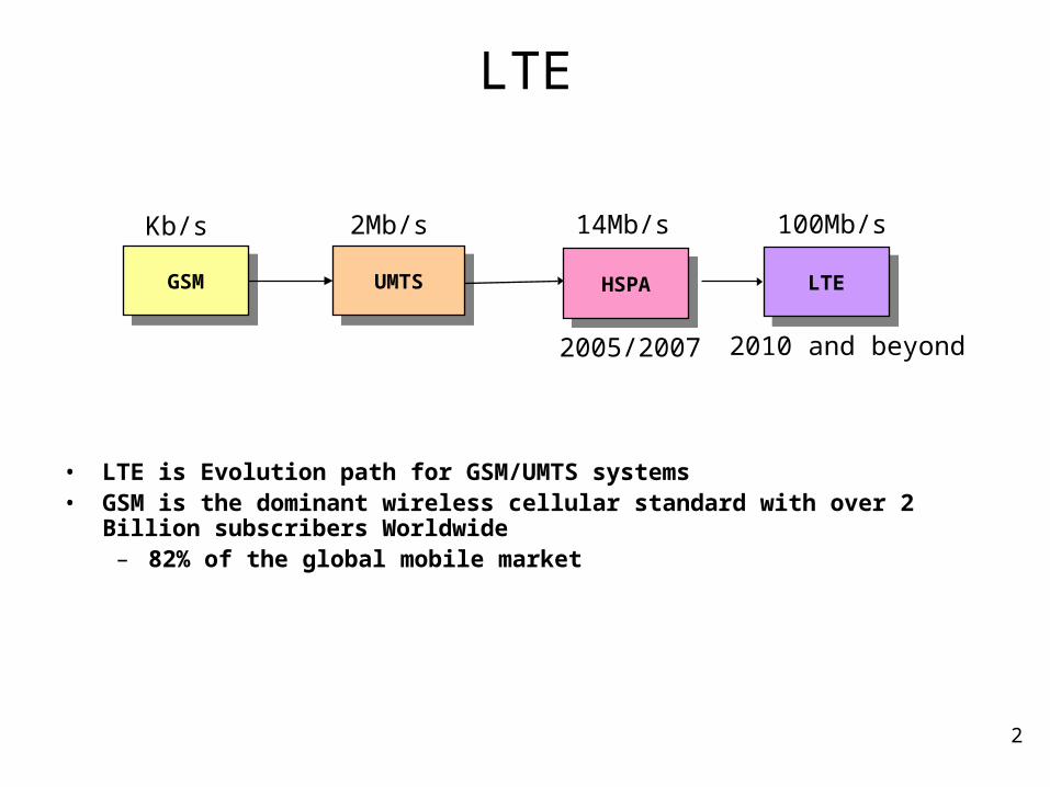
LTE
• LTE is Evolution path for GSM/UMTS systems • GSM is the dominant wireless cellular standard with over 2 Billion subscribers
Worldwide– 82% of the global mobile market
UMTSUMTSHSPAHSPA LTELTEGSMGSM
2005/2007 2010 and beyond
2Mb/s 100Mb/s14Mb/sKb/s
3
Tutorial Outline (1/2)
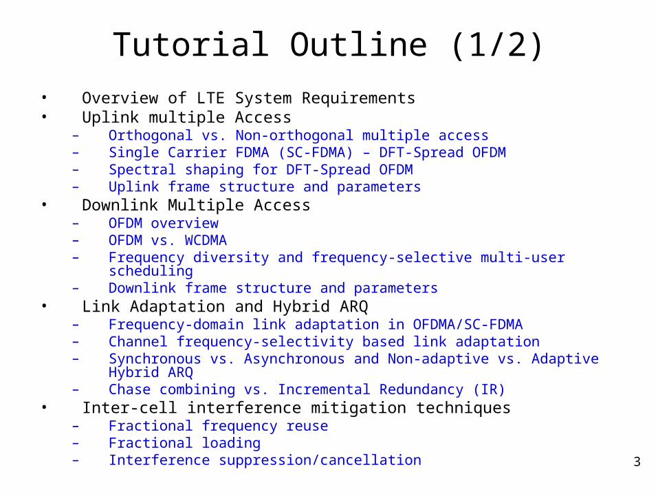
• Overview of LTE System Requirements• Uplink multiple Access
– Orthogonal vs. Non-orthogonal multiple access– Single Carrier FDMA (SC-FDMA) – DFT-Spread OFDM– Spectral shaping for DFT-Spread OFDM– Uplink frame structure and parameters
• Downlink Multiple Access– OFDM overview– OFDM vs. WCDMA– Frequency diversity and frequency-selective multi-user scheduling– Downlink frame structure and parameters
• Link Adaptation and Hybrid ARQ– Frequency-domain link adaptation in OFDMA/SC-FDMA– Channel frequency-selectivity based link adaptation– Synchronous vs. Asynchronous and Non-adaptive vs. Adaptive Hybrid ARQ– Chase combining vs. Incremental Redundancy (IR)
• Inter-cell interference mitigation techniques– Fractional frequency reuse– Fractional loading– Interference suppression/cancellation
4
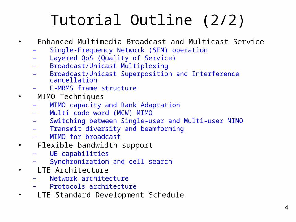
Tutorial Outline (2/2)• Enhanced Multimedia Broadcast and Multicast Service
– Single-Frequency Network (SFN) operation– Layered QoS (Quality of Service)– Broadcast/Unicast Multiplexing– Broadcast/Unicast Superposition and Interference cancellation– E-MBMS frame structure
• MIMO Techniques– MIMO capacity and Rank Adaptation– Multi code word (MCW) MIMO– Switching between Single-user and Multi-user MIMO– Transmit diversity and beamforming– MIMO for broadcast
• Flexible bandwidth support– UE capabilities– Synchronization and cell search
• LTE Architecture– Network architecture– Protocols architecture
• LTE Standard Development Schedule
5
LTE System Requirements
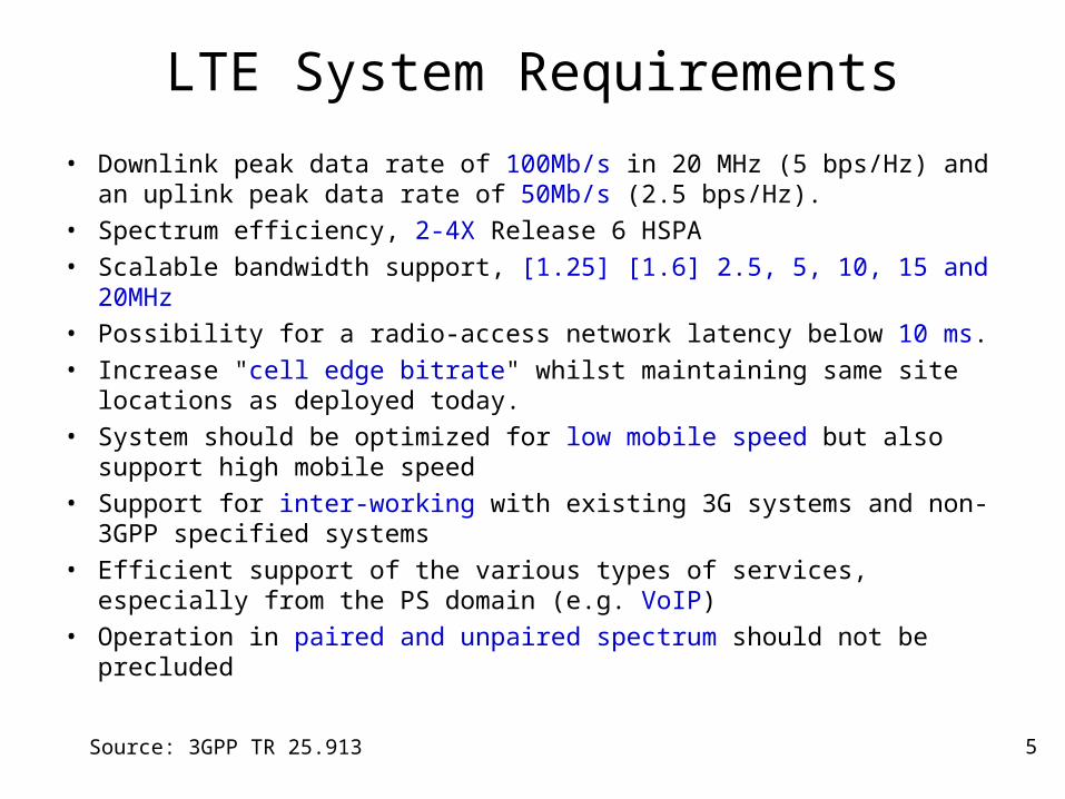
• Downlink peak data rate of 100Mb/s in 20 MHz (5 bps/Hz) and an uplink peak data rate of 50Mb/s (2.5 bps/Hz).
• Spectrum efficiency, 2-4X Release 6 HSPA• Scalable bandwidth support, [1.25] [1.6] 2.5, 5, 10, 15 and 20MHz• Possibility for a radio-access network latency below 10 ms.• Increase "cell edge bitrate" whilst maintaining same site locations as
deployed today.• System should be optimized for low mobile speed but also support
high mobile speed • Support for inter-working with existing 3G systems and non-3GPP
specified systems • Efficient support of the various types of services, especially from the
PS domain (e.g. VoIP) • Operation in paired and unpaired spectrum should not be precluded
Source: 3GPP TR 25.913
6
Uplink Multiple Access
7
Uplink Multiple Access
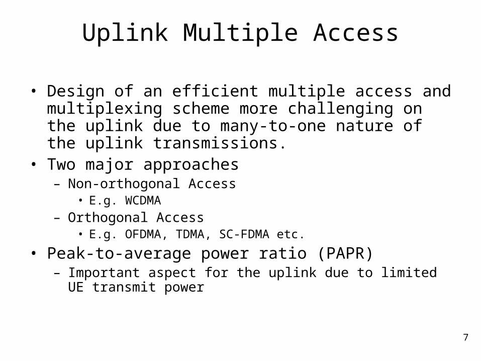
• Design of an efficient multiple access and multiplexing scheme more challenging on the uplink due to many-to-one nature of the uplink transmissions.
• Two major approaches– Non-orthogonal Access
• E.g. WCDMA
– Orthogonal Access• E.g. OFDMA, TDMA, SC-FDMA etc.
• Peak-to-average power ratio (PAPR)– Important aspect for the uplink due to limited UE transmit power
8
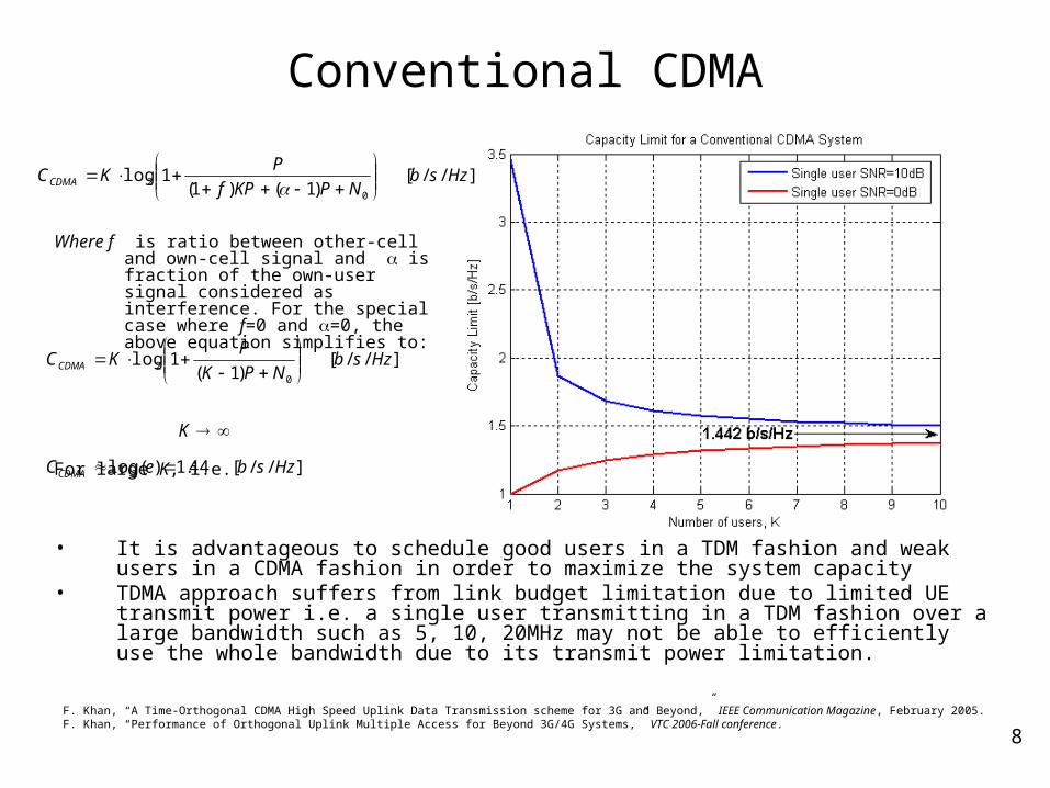
Conventional CDMA
F. Khan, “A Time-Orthogonal CDMA High Speed Uplink Data Transmission scheme for 3G and Beyond,” IEEE Communication Magazine, February 2005.F. Khan, “Performance of Orthogonal Uplink Multiple Access for Beyond 3G/4G Systems,” VTC 2006-Fall conference.
• It is advantageous to schedule good users in a TDM fashion and weak users in a CDMA fashion in order to maximize the system capacity
• TDMA approach suffers from link budget limitation due to limited UE transmit power i.e. a single user transmitting in a TDM fashion over a large bandwidth such as 5, 10, 20MHz may not be able to efficiently use the whole bandwidth due to its transmit power limitation.
]//[)1()1(
1log0
2 HzsbNPKPf
PKCCDMA
Where f is ratio between other-cell and own-cell signal and is fraction of the own-user signal considered as interference. For the special case where f=0 and =0, the above equation simplifies to:
For large K, i.e.
]//[)1(
1log0
2 HzsbNPK
PKCCDMA
]//[44.1)(log2 HzsbeCCDMA
K
9
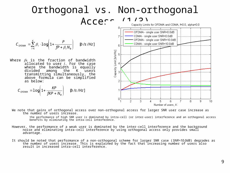
Orthogonal vs. Non-orthogonal Access (1/3)
Where is the fraction of bandwidth allocated to user i. For the case where the bandwidth is equally divided among the K users transmitting simultaneously, the above formula can be simplified as below:
]//[1log0
21
HzsbNfP
PC
i
K
iiOFDMA
]//[1log0
2 HzsbNfKP
KPCOFDMA
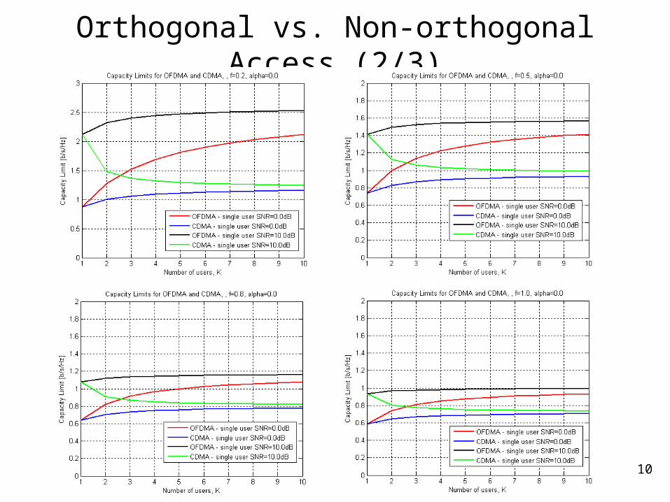
We note that gains of orthogonal access over non-orthogonal access for larger SNR user case increase as the number of users increase.
the performance of high SNR user is dominated by intra-cell (or inter-user) interference and an orthogonal access benefits by eliminating the intra-cell interference.
However, the performance of a weak user is dominated by the inter-cell interference and the background noise and eliminating intra-cell interference by using orthogonal access only provides small advantage.
It should be noted that performance of a non-orthogonal scheme for larger SNR case (SNR=10.0dB) degrades as the number of users increase. This is explained by the fact that increasing number of users also result in increased intra-cell interference.
10
Orthogonal vs. Non-orthogonal Access (2/3)
11
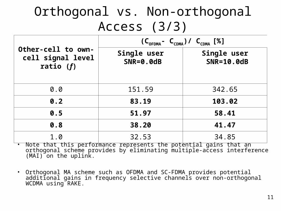
Orthogonal vs. Non-orthogonal Access (3/3)
Other-cell to own-cell signal level ratio (f)
(COFDMA- CCDMA)/ CCDMA [%]
Single user SNR=0.0dB
Single user SNR=10.0dB
0.0 151.59 342.65
0.2 83.19 103.02
0.5 51.97 58.41
0.8 38.20 41.47
1.0 32.53 34.85
• Note that this performance represents the potential gains that an orthogonal scheme provides by eliminating multiple-access interference (MAI) on the uplink.
• Orthogonal MA scheme such as OFDMA and SC-FDMA provides potential additional gains in frequency selective channels over non-orthogonal WCDMA using RAKE.
12
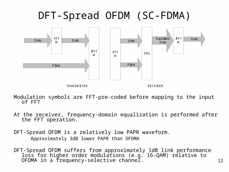
DFT-Spread OFDM (SC-FDMA)
IFFTN
FFTM
Data Data
Pilots
FFTN
IFFTM
Data
FDE
Data
Pilots
EqualizedData
TRANSMITTER RECEIVER
Modulation symbols are FFT-pre-coded before mapping to the input of FFT
At the receiver, frequency-domain equalization is performed after the FFT operation.
DFT-Spread OFDM is a relatively low PAPR waveform.Approximately 3dB lower PAPR than OFDMA
DFT-Spread OFDM suffers from approximately 1dB link performance loss for higher order modulations (e.g. 16-QAM) relative to OFDMA in a frequency-selective channel.
13
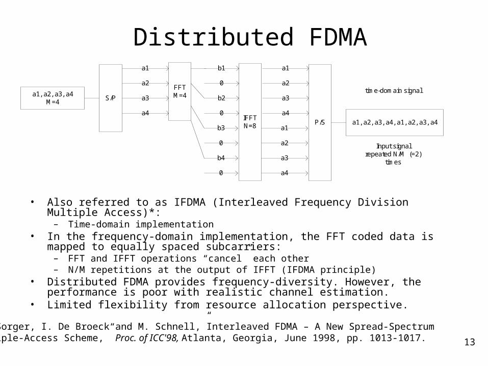
Distributed FDMA
IFFTN=8
FFTM=4
a1
a2
a3
a4
b1
0
b2
0
b3
0
b4
0
a1
a2
a3
a4
a1
a2
a3
a4
a1, a2, a3, a4M=4
a1, a2, a3, a4, a1, a2, a3, a4
S/P
P/S
Input signalrepeated N/M (=2)
times
time-domain signal
• Also referred to as IFDMA (Interleaved Frequency Division Multiple Access)*:– Time-domain implementation
• In the frequency-domain implementation, the FFT coded data is mapped to equally spaced subcarriers:
– FFT and IFFT operations “cancel” each other– N/M repetitions at the output of IFFT (IFDMA principle)
• Distributed FDMA provides frequency-diversity. However, the performance is poor with realistic channel estimation.
• Limited flexibility from resource allocation perspective.
*U. Sorger, I. De Broeck and M. Schnell,”Interleaved FDMA – A New Spread-Spectrum Multiple-Access Scheme,” Proc. of ICC'98, Atlanta, Georgia, June 1998, pp. 1013-1017.
14
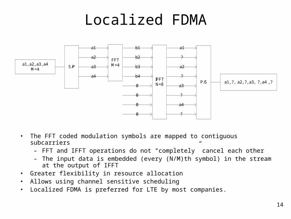
Localized FDMA
IFFTN=8
FFTM=4
a1
a2
a3
a4
b1
b2
b3
b4
0
0
0
0
a1
?
a2
?
a3
?
a4
?
a1, a2, a3, a4M=4
a1, ?, a2, ?, a3, ?, a4 , ?
S/P
P/S
• The FFT coded modulation symbols are mapped to contiguous subcarriers– FFT and IFFT operations do not “completely” cancel each other– The input data is embedded (every (N/M)th symbol) in the stream at the output of
IFFT• Greater flexibility in resource allocation• Allows using channel sensitive scheduling• Localized FDMA is preferred for LTE by most companies.
15
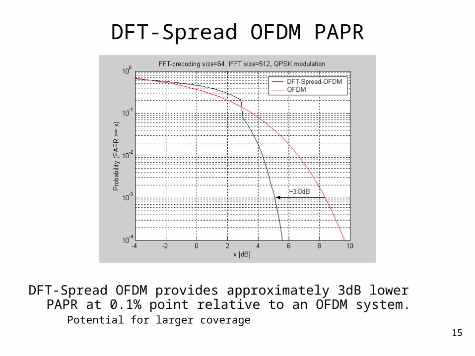
DFT-Spread OFDM PAPR
DFT-Spread OFDM provides approximately 3dB lower PAPR at 0.1% point relative to an OFDM system.
Potential for larger coverage
16
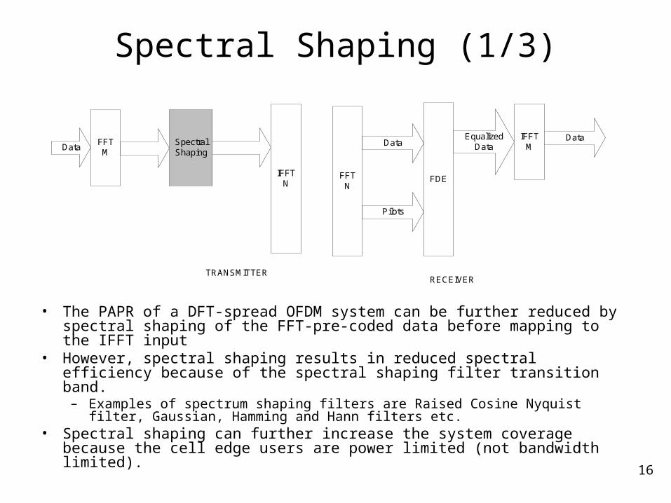
Spectral Shaping (1/3)
• The PAPR of a DFT-spread OFDM system can be further reduced by spectral shaping of the FFT-pre-coded data before mapping to the IFFT input
• However, spectral shaping results in reduced spectral efficiency because of the spectral shaping filter transition band.
– Examples of spectrum shaping filters are Raised Cosine Nyquist filter, Gaussian, Hamming and Hann filters etc.
• Spectral shaping can further increase the system coverage because the cell edge users are power limited (not bandwidth limited).
IFFTN
FFTM
Data
FFTN
IFFTM
Data
FDE
Data
Pilots
EqualizedData
TRANSMITTERRECEIVER
SpectralShaping
17
Spectral Shaping (2/3)
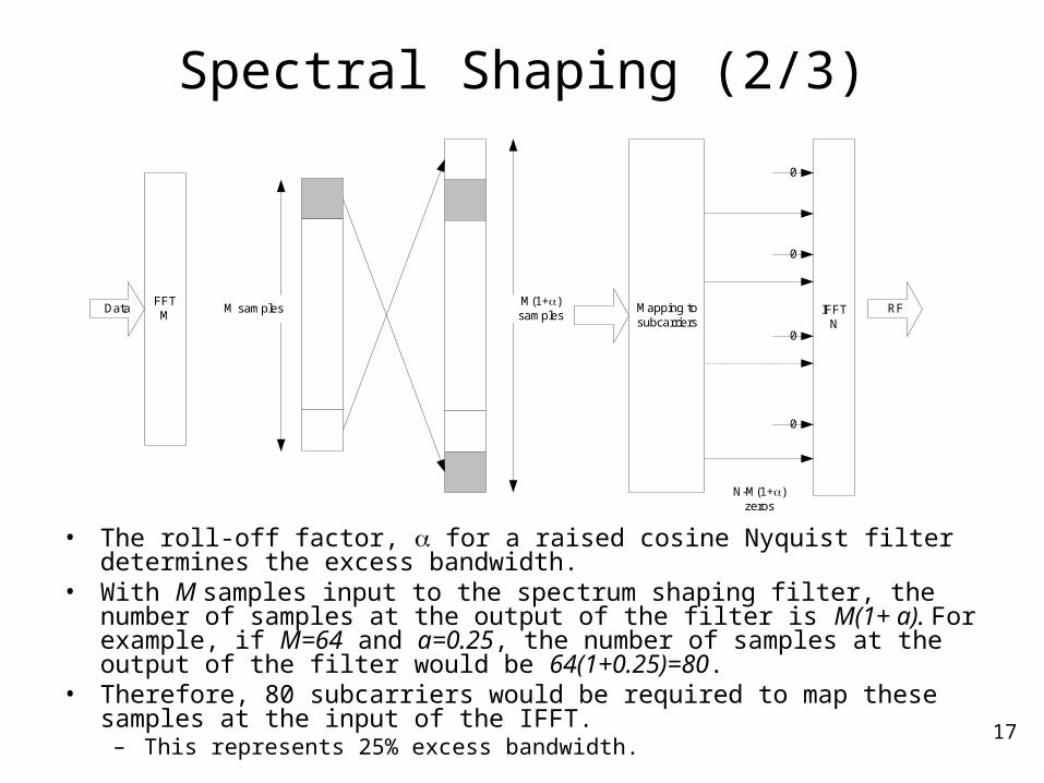
• The roll-off factor, for a raised cosine Nyquist filter determines the excess bandwidth.
• With M samples input to the spectrum shaping filter, the number of samples at the output of the filter is M(1+ a). For example, if M=64 and a=0.25, the number of samples at the output of the filter would be 64(1+0.25)=80.
• Therefore, 80 subcarriers would be required to map these samples at the input of the IFFT.
– This represents 25% excess bandwidth.
Mapping tosubcarriers
FFTM
Data M samplesM(1+)samples IFFT
N
0
0
0
0
N-M(1+)zeros
RF
18
Spectral Shaping (3/3)
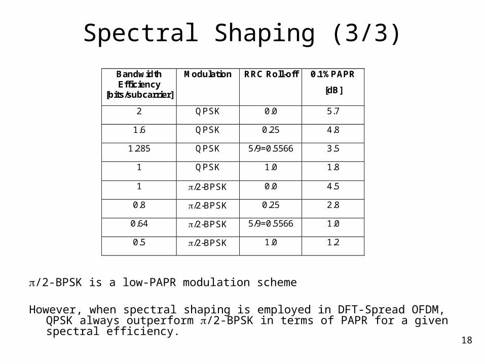
Bandwidth Efficiency
[bits/subcarrier]
Modulation RRC Roll-off 0.1%PAPR
[dB]
2 QPSK 0.0 5.7
1.6 QPSK 0.25 4.8
1.285 QPSK 5/9=0.5566 3.5
1 QPSK 1.0 1.8
1 /2-BPSK 0.0 4.5
0.8 /2-BPSK 0.25 2.8
0.64 /2-BPSK 5/9=0.5566 1.0
0.5 /2-BPSK 1.0 1.2
/2-BPSK is a low-PAPR modulation scheme
However, when spectral shaping is employed in DFT-Spread OFDM, QPSK always outperform /2-BPSK in terms of PAPR for a given spectral efficiency.
19
Uplink Structure
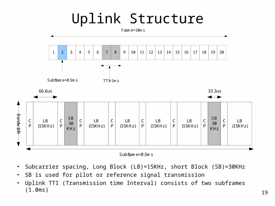
• Subcarrier spacing, Long Block (LB)=15KHz, short Block (SB)=30KHz
• SB is used for pilot or reference signal transmission
• Uplink TTI (Transmission time Interval) consists of two subframes (1.0ms)
LB(15KHz)
CP
SB30
KHz
CP
LB(15KHz)
CP
LB(15KHz)
CP
LB(15KHz)
CP
LB(15KHz)
CP
SB30
KHz
CP
LB(15KHz)
CP
66.6us 33.3us
Subframe=0.5ms
Ba
nd
wid
th
Frame=10ms
1 2 3 4 5 6 7 8 9 10 11 12 13 14 15 16 17 18 19 20
Subframe=0.5ms TTI=1ms
20
Uplink Parameters
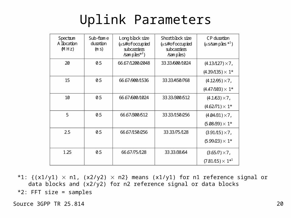
*1: {(x1/y1) n1, (x2/y2) n2} means (x1/y1) for n1 reference signal or data blocks and (x2/y2) for n2 reference signal or data blocks
*2: FFT size = samples
Source 3GPP TR 25.814
Spectrum Allocation
(MHz)
Sub-frame duration
(ms)
Long block size (s/#of occupied
subcarriers /samples*2)
Short block size (s/#of occupied
subcarriers /samples)
CP duration (s/samples *1)
20 0.5 66.67/1200/2048 33.33/600/1024 (4.13/127) 7,
(4.39/135) 1*
15 0.5 66.67/900/1536 33.33/450/768 (4.12/95) 7,
(4.47/103) 1*
10 0.5 66.67/600/1024 33.33/300/512 (4.1/63) 7,
(4.62/71) 1*
5 0.5 66.67/300/512 33.33/150/256 (4.04/31) 7,
(5.08/39) 1*
2.5 0.5
66.67/150/256 33.33/75/128 (3.91/15) 7,
(5.99/23) 1*
1.25 0.5 66.67/75/128 33.33/38/64 (3.65/7) 7,
(7.81/15) 1*1
21
Downlink Multiple Access
22
OFDM (1/2)
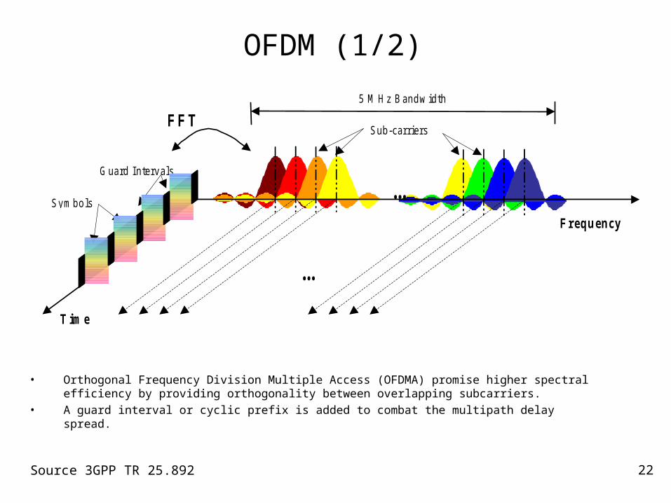
• Orthogonal Frequency Division Multiple Access (OFDMA) promise higher spectral efficiency by providing orthogonality between overlapping subcarriers.
• A guard interval or cyclic prefix is added to combat the multipath delay spread.
…
S u b -c a r r ie rsF F T
T im e
S y m b o ls
5 M H z B a n d w id th
G u a rd I n te rv a ls
…
F r e q u en c y
Source 3GPP TR 25.892

23
OFDM (2/2)
• OFDM requires a single IFFT operation at the transmitter and a single FFT operation at the receiver.
• In contrast, DFT-Spread OFDM requires two FFT/IFFT operations at the transmitter and two FFT/IFFT operations at the receiver.
IFFT
TRANSMITTER
RECEIVER
P/SS/PMod.
SymbolsAddCP
RF
S/P FFTRemoveCP
Receive P/SMod.
Symbols
QAMMod.
Coded bits
QAMDemod.
to decoder
24
OFDM vs. WCDMA (1/2)
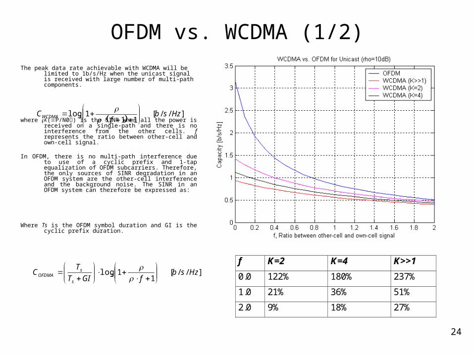
The peak data rate achievable with WCDMA will be limited to 1b/s/Hz when the unicast signal is received with large number of multi-path components.
where (P/N0) is the SINR when all the power is received on a single-path and there is no interference from the other cells. f represents the ratio between other-cell and own-cell signal.
In OFDM, there is no multi-path interference due to use of a cyclic prefix and 1-tap equalization of OFDM subcarriers. Therefore, the only sources of SINR degradation in an OFDM system are the other-cell interference and the background noise. The SINR in an OFDM system can therefore be expressed as:
Where Ts is the OFDM symbol duration and GI is the cyclic prefix duration.
]//[11
1log 2 Hzsbf
CWCDMA
]//[1
1log 2 HzsbfGIT
TC
s
sOFDMA
f K=2 K=4 K>>1
0.0 122% 180% 237%
1.0 21% 36% 51%
2.0 9% 18% 27%
25
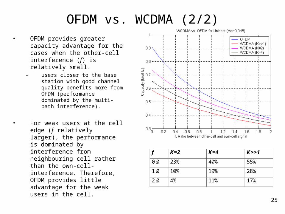
OFDM vs. WCDMA (2/2)• OFDM provides greater capacity
advantage for the cases when the other-cell interference (f) is relatively small.
– users closer to the base station with good channel quality benefits more from OFDM (performance dominated by the multi-path interference).
• For weak users at the cell edge (f relatively larger), the performance is dominated by interference from neighbouring cell rather than the own-cell-interference. Therefore, OFDM provides little advantage for the weak users in the cell.
f K=2 K=4 K>>1
0.0 23% 40% 55%
1.0 10% 19% 28%
2.0 4% 11% 17%
26
OFDM vs. WCDMA w/ advanced receiver
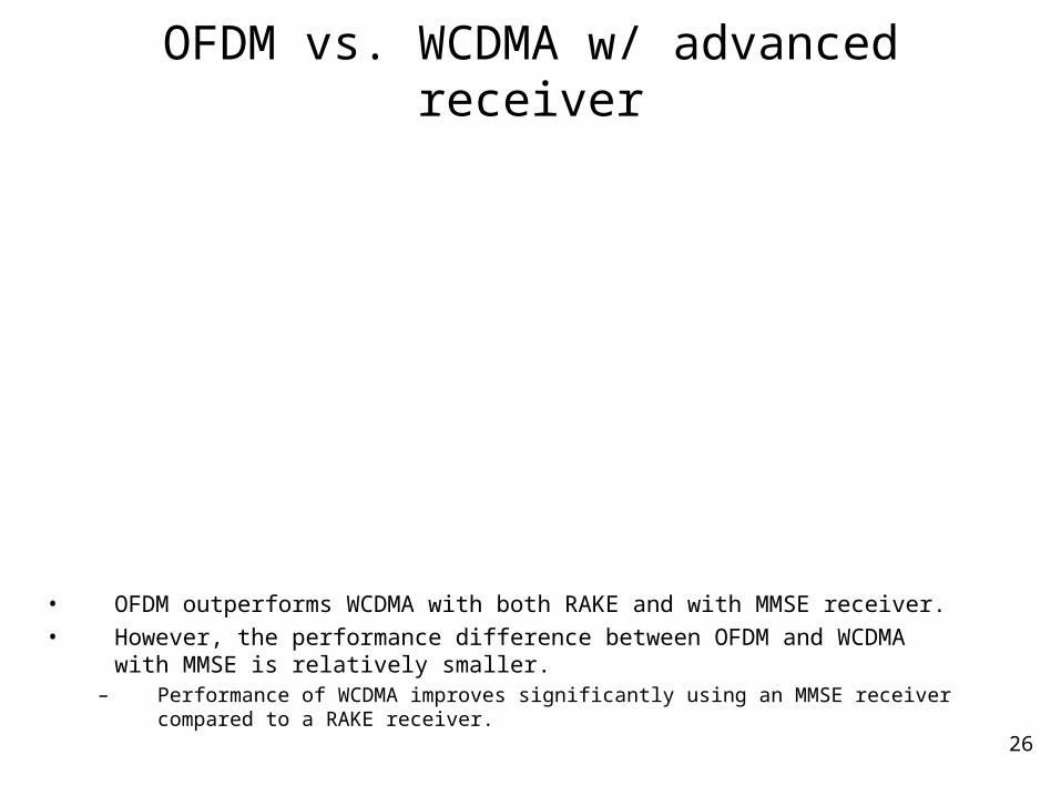
• OFDM outperforms WCDMA with both RAKE and with MMSE receiver.• However, the performance difference between OFDM and WCDMA with MMSE
is relatively smaller. – Performance of WCDMA improves significantly using an MMSE receiver compared to
a RAKE receiver.
Performance of WCDMA vs. OFDM Unicast:Mixed Ped A and B at 50:50, 3km/h, Proportional Fair scheduler
0.0
1.0
2.0
3.0
4.0
5.0
6.0
7.0
0 5 10 15 20 25 30
Number of users per sector
Sect
or
Thro
ughput
[Mbps]
OFDM
WCDMA(RAKE)
WCDMA(MMSE)
27
Frequency-diversity and scheduling
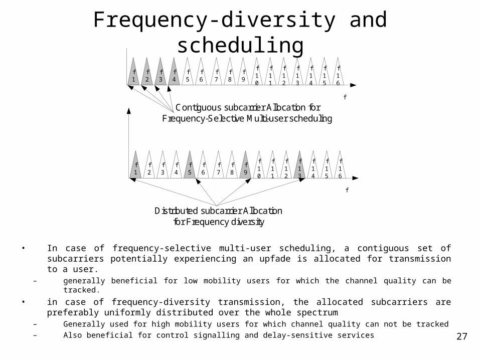
• In case of frequency-selective multi-user scheduling, a contiguous set of subcarriers potentially experiencing an upfade is allocated for transmission to a user.
– generally beneficial for low mobility users for which the channel quality can be tracked.
• in case of frequency-diversity transmission, the allocated subcarriers are preferably uniformly distributed over the whole spectrum
– Generally used for high mobility users for which channel quality can not be tracked
– Also beneficial for control signalling and delay-sensitive services
Distributed subcarrier Allocationfor Frequency diversity
f1
f2
f3
f4
f5
f6
f7
f8
f9
f10
f11
f12
f13
f14
f15
f16
f
Contiguous subcarrier Allocation forFrequency-Selective Multi-user scheduling
f1
f2
f3
f4
f5
f6
f7
f8
f9
f10
f11
f12
f13
f14
f15
f16
f
28
Frequency-selective multi-user scheduling
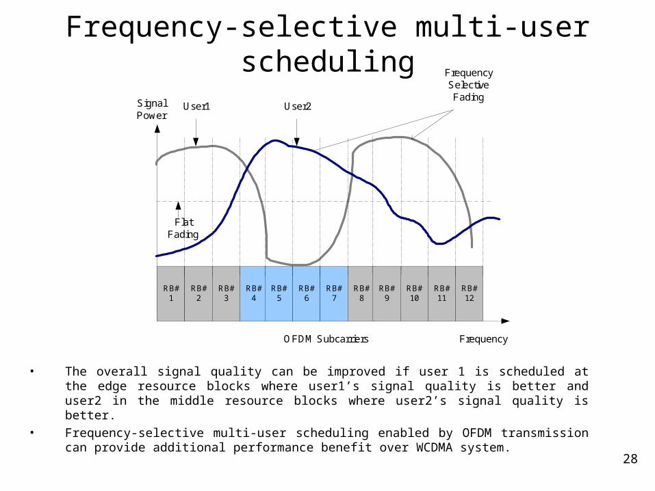
• The overall signal quality can be improved if user 1 is scheduled at the edge resource blocks where user1’s signal quality is better and user2 in the middle resource blocks where user2’s signal quality is better.
• Frequency-selective multi-user scheduling enabled by OFDM transmission can provide additional performance benefit over WCDMA system.
FrequencyOFDM Subcarriers
FlatFading
User1SignalPower
User2
FrequencySelectiveFading
RB#1
RB#2
RB#3
RB#4
RB#5
RB#6
RB#7
RB#8
RB#9
RB#10
RB#11
RB#12
29
OFDM w/ Frequency-selective scheduling
• Frequency-selective multi-user scheduling provides additional throughput gain on top of multi-user diversity using time-domain scheduling.
• The channel quality feedback overhead is larger for a system employing frequency-selective multi-user scheduling.
Frequency Scheduling Gain in OFDMA with Contiguous Structure:Channel Model: Ped B
3.0
4.0
5.0
6.0
7.0
8.0
0 5 10 15 20 25 30
Number of users per sector
Sect
or T
hro
ughput
[Mbps]
# of sub-bands: 1
# of sub-bands: 8
30
Downlink Frame Structure
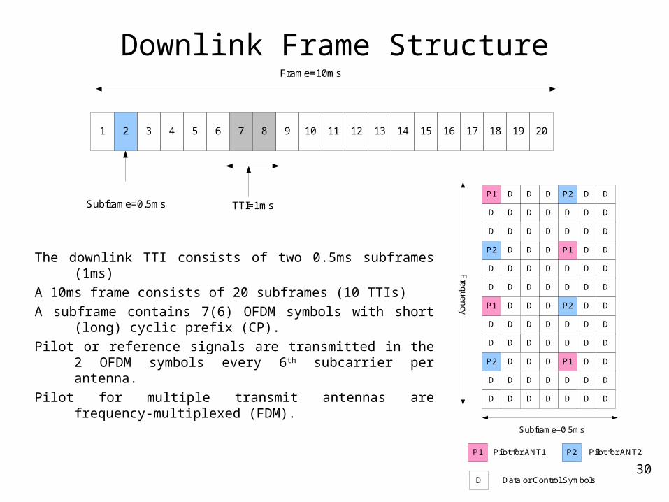
The downlink TTI consists of two 0.5ms subframes (1ms)
A 10ms frame consists of 20 subframes (10 TTIs)
A subframe contains 7(6) OFDM symbols with short (long) cyclic prefix (CP).
Pilot or reference signals are transmitted in the 2 OFDM symbols every 6th subcarrier per antenna.
Pilot for multiple transmit antennas are frequency-multiplexed (FDM).
Subframe=0.5ms
P1
D
D
P2
D
D
P1
D
D
P2
D
D
D
D
D
D
D
D
D
D
D
D
D
D
D
D
D
D
D
D
D
D
D
D
D
D
D
D
D
D
D
D
D
D
D
D
D
D
P2
D
D
P1
D
D
P2
D
D
P1
D
D
D
D
D
D
D
D
D
D
D
D
D
D
Fre
qu
en
cy
D
D
D
D
D
D
D
D
D
D
D
D
P1 Pilot for ANT1 P2 Pilot for ANT2
D Data or Control Symbols
Frame=10ms
1 2 3 4 5 6 7 8 9 10 11 12 13 14 15 16 17 18 19 20
Subframe=0.5ms TTI=1ms
31
Downlink Parameters
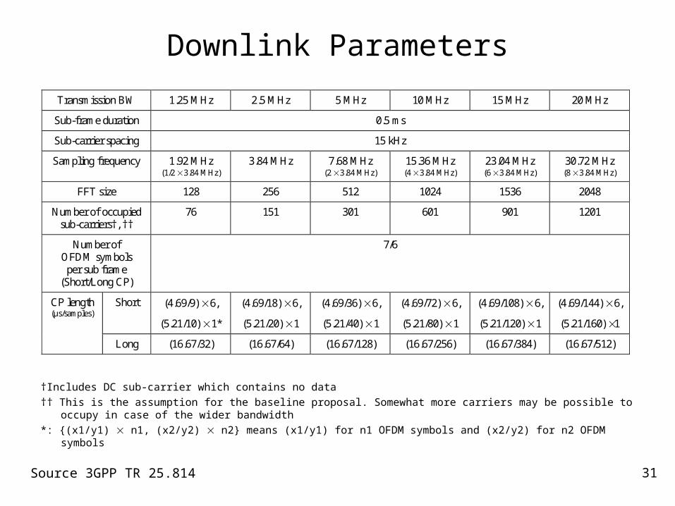
Transmission BW 1.25 MHz 2.5 MHz 5 MHz 10 MHz 15 MHz 20 MHz
Sub-frame duration 0.5 ms
Sub-carrier spacing 15 kHz
Sampling frequency 1.92 MHz (1/2 3.84 MHz)
3.84 MHz 7.68 MHz (2 3.84 MHz)
15.36 MHz (4 3.84 MHz)
23.04 MHz (6 3.84 MHz)
30.72 MHz (8 3.84 MHz)
FFT size 128 256 512 1024 1536 2048
Number of occupied sub-carriers†, ††
76 151 301 601 901 1201
Number of OFDM symbols per sub frame
(Short/Long CP)
7/6
Short (4.69/9) 6,
(5.21/10) 1*
(4.69/18) 6,
(5.21/20) 1
(4.69/36) 6,
(5.21/40) 1
(4.69/72) 6,
(5.21/80) 1
(4.69/108) 6,
(5.21/120) 1
(4.69/144) 6,
(5.21/160) 1
CP length (μs/samples)
Long (16.67/32) (16.67/64) (16.67/128) (16.67/256) (16.67/384) (16.67/512)
†Includes DC sub-carrier which contains no data
†† This is the assumption for the baseline proposal. Somewhat more carriers may be possible to occupy in case of the wider bandwidth
*: {(x1/y1) n1, (x2/y2) n2} means (x1/y1) for n1 OFDM symbols and (x2/y2) for n2 OFDM symbols
Source 3GPP TR 25.814
32
Link Adaptation and Hybrid ARQ
33
Link Adaptation and Hybrid ARQ
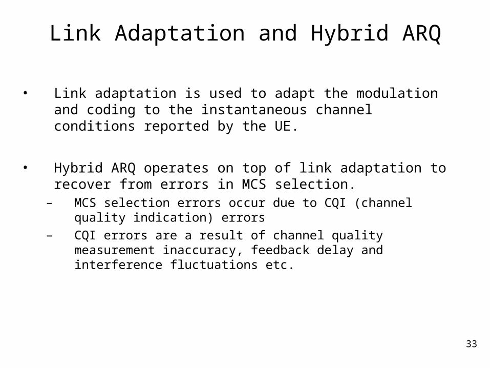
• Link adaptation is used to adapt the modulation and coding to the instantaneous channel conditions reported by the UE.
• Hybrid ARQ operates on top of link adaptation to recover from errors in MCS selection.
– MCS selection errors occur due to CQI (channel quality indication) errors
– CQI errors are a result of channel quality measurement inaccuracy, feedback delay and interference fluctuations etc.
34
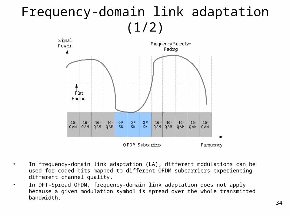
Frequency-domain link adaptation (1/2)
• In frequency-domain link adaptation (LA), different modulations can be used for coded bits mapped to different OFDM subcarriers experiencing different channel quality.
• In DFT-Spread OFDM, frequency-domain link adaptation does not apply because a given modulation symbol is spread over the whole transmitted bandwidth.
FrequencyOFDM Subcarriers
FlatFading
SignalPower Frequency Selective
Fading
16-QAM
16-QAM
16-QAM
16-QAM
QPSK
QPSK
QPSK
16-QAM
16-QAM
16-QAM
16-QAM
16-QAM

35
Frequency-domain link adaptation (2/2)
• LTE system does not employ frequency-domain link adaptation:– A common modulation is selected for all the coded symbols transmitted.
Source 3GPP TR 25.814
Transport block (L2 PDU)
CRC attachment
Channel coding
HARQ functionalityincluding adaptive
coding rate
Physical channel segmentation
(resource block mapping)
Adaptive modulation(common modulation is selected)
To assigned resource blocks
Number of assigned resource blocks
36
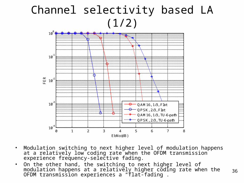
Channel selectivity based LA (1/2)
0 1 2 3 4 5 6 7 810
-4
10-3
10-2
10-1
100
EbNo(dB)
FE
R
QAM16, 1/3, Flat
QPSK, 2/3, FlatQAM16, 1/3, TU-6-path
QPSK, 2/3, TU-6-path
• Modulation switching to next higher level of modulation happens at a relatively low coding rate when the OFDM transmission experience frequency-selective fading.
• On the other hand, the switching to next higher level of modulation happens at a relatively higher coding rate when the OFDM transmission experiences a “flat-fading”.
37
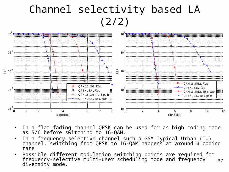
Channel selectivity based LA (2/2)
• In a flat-fading channel QPSK can be used for as high coding rate as 5/6 before switching to 16-QAM.
• In a frequency-selective channel such a GSM Typical Urban (TU) channel, switching from QPSK to 16-QAM happens at around ½ coding rate.
• Possible different modulation switching points are required for frequency-selective multi-user scheduling mode and frequency diversity mode.
0 1 2 3 4 5 6 7 810
-4
10-3
10-2
10-1
100
EbNo(dB)
FE
R
QAM16, 3/8, Flat
QPSK, 3/4, Flat
QAM16, 3/8, TU-6-path
QPSK, 3/4, TU-6-path
0 2 4 6 8 10 1210
-4
10-3
10-2
10-1
100
EbNo(dB)F
ER
QAM16, 5/12, Flat
QPSK, 5/6, FlatQAM16, 5/12, TU-6-path
QPSK, 5/6, TU-6-path
38
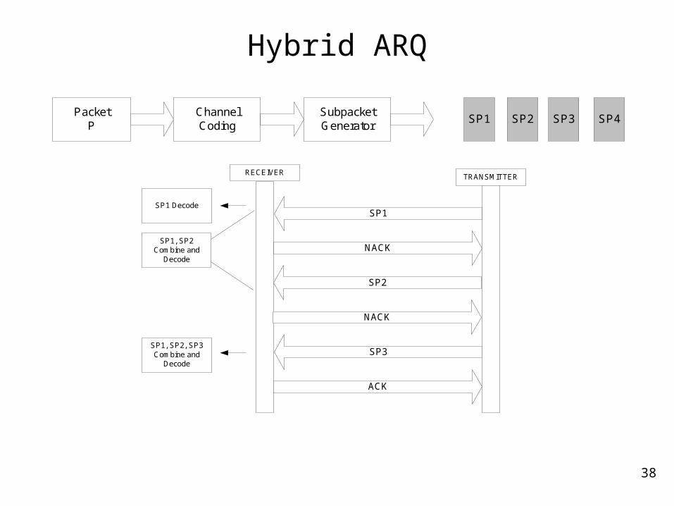
Hybrid ARQ
SP1Packet
PChannelCoding
SubpacketGenerator
SP2 SP3 SP4
RECEIVER
NACK
TRANSMITTER
SP1
NACK
SP2
ACK
SP3
SP1, SP2Combine and
Decode
SP1 Decode
SP1, SP2, SP3Combine and
Decode
39
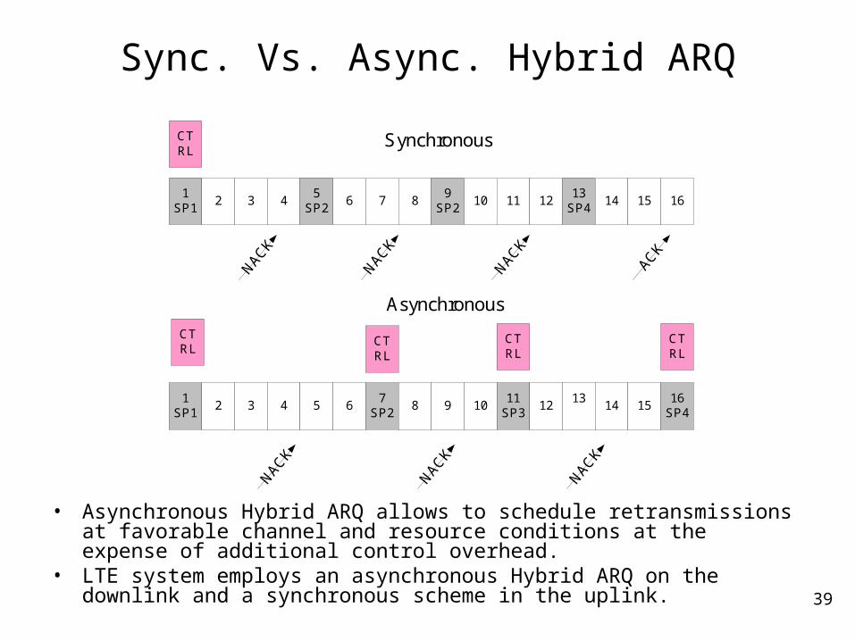
Sync. Vs. Async. Hybrid ARQ
• Asynchronous Hybrid ARQ allows to schedule retransmissions at favorable channel and resource conditions at the expense of additional control overhead.
• LTE system employs an asynchronous Hybrid ARQ on the downlink and a synchronous scheme in the uplink.
1SP1
2 3 45
SP26 7 8
9SP2
10 11 1213
SP414 15 16
CTRL
NACK
NACK
NACK
ACK
1SP1
2 3 4 5 67
SP28 9 10
11SP3
1213
14 1516
SP4
CTRL
CTRL
CTRL
CTRL
NACK
NACK
NACK
Synchronous
Asynchronous
40
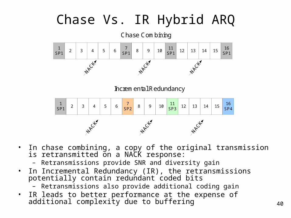
Chase Vs. IR Hybrid ARQ
• In chase combining, a copy of the original transmission is retransmitted on a NACK response:
– Retransmissions provide SNR and diversity gain• In Incremental Redundancy (IR), the retransmissions potentially contain
redundant coded bits– Retransmissions also provide additional coding gain
• IR leads to better performance at the expense of additional complexity due to buffering
1SP1
2 3 4 5 67
SP28 9 10
11SP3
12 13 14 1516
SP4
Incremental Redundancy
1SP1
2 3 4 5 67
SP18 9 10
11SP1
12 13 14 1516
SP1
Chase Combining
41
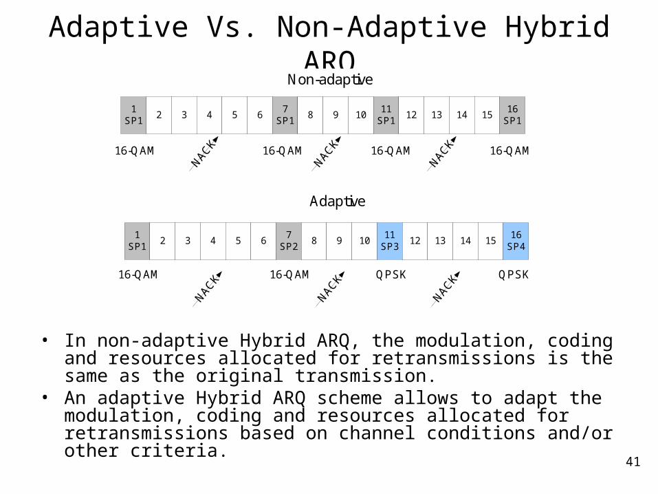
Adaptive Vs. Non-Adaptive Hybrid ARQ
• In non-adaptive Hybrid ARQ, the modulation, coding and resources allocated for retransmissions is the same as the original transmission.
• An adaptive Hybrid ARQ scheme allows to adapt the modulation, coding and resources allocated for retransmissions based on channel conditions and/or other criteria.
1SP1
2 3 4 5 67
SP28 9 10
11SP3
12 13 14 1516
SP4
Adaptive
1SP1
2 3 4 5 67
SP18 9 10
11SP1
12 13 14 1516
SP1
Non-adaptive
16-QAM 16-QAM 16-QAM 16-QAM
16-QAM 16-QAM QPSK QPSK
42
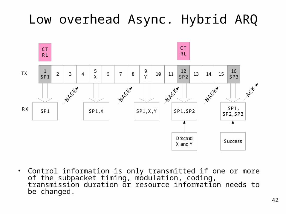
Low overhead Async. Hybrid ARQ
• Control information is only transmitted if one or more of the subpacket timing, modulation, coding, transmission duration or resource information needs to be changed.
1SP1
2 3 45X
6 7 89Y
10 1112
SP213 14 15
16SP3
CTRL
CTRL
SP1 SP1, X SP1, X, Y SP1, SP2SP1,
SP2, SP3
DiscardX and Y
Success
TX
RX
NACK
NACK
NACK
NACK
ACK
43
Inter-Cell Interference Mitigation Techniques
44
Fractional Frequency Reuse
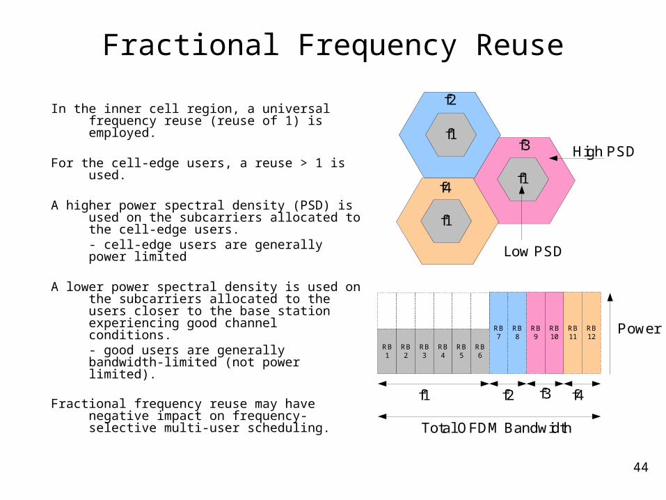
In the inner cell region, a universal frequency reuse (reuse of 1) is employed.
For the cell-edge users, a reuse > 1 is used.
A higher power spectral density (PSD) is used on the subcarriers allocated to the cell-edge users.- cell-edge users are generally power limited
A lower power spectral density is used on the subcarriers allocated to the users closer to the base station experiencing good channel conditions.- good users are generally bandwidth-limited (not power limited).
Fractional frequency reuse may have negative impact on frequency-selective multi-user scheduling.
f1
f1
f1
f2
f4
f3
Low PSD
High PSD
RB1
RB2
RB3
RB4
RB6
RB7
RB8
RB9
RB11
RB12
RB5
RB10
f1 f2 f3 f4
Power
Total OFDM Bandwidth
45
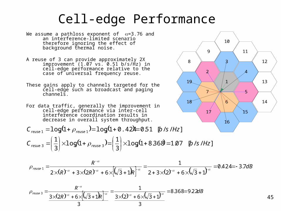
Cell-edge Performance We assume a pathloss exponent of =3.76 and an
interference-limited scenario therefore ignoring the effect of background thermal noise.
A reuse of 3 can provide approximately 2X improvement (1.07 vs. 0.51 b/s/Hz) in cell-edge performance relative to the case of universal frequency reuse.
These gains apply to channels targeted for the cell-edge such as broadcast and paging channels.
For data traffic, generally the improvement in cell-edge performance via inter-cell interference coordination results in decrease in overall system throughput.
57
1
6
4
3
2
13
14
15
12
11
10
9
8
19
18
17
16
dBRRR
Rreuse 7.3424.0
136232
1
1362321
dBRR
Rreuse 22.9368.8
3
13623
1
3
136233
]//[07.1368.81log3
11log
3
1
]//[51.00.4241log1log
2323
2121
HzsbC
HzsbC
reuseresue
reusereuse
46
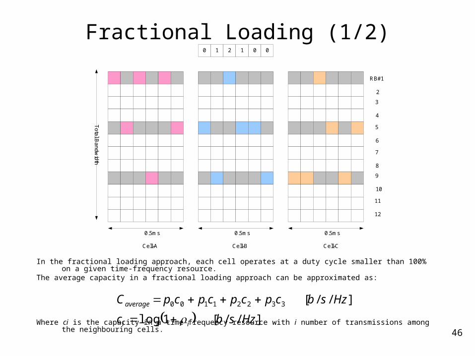
Fractional Loading (1/2)
In the fractional loading approach, each cell operates at a duty cycle smaller than 100% on a given time-frequency resource.
The average capacity in a fractional loading approach can be approximated as:
Where ci is the capacity in a time-frequency resource with i number of transmissions among the neighbouring cells.
0.5ms 0.5ms 0.5ms
0 1 2 1 0 0
To
tal B
andwidth
Cell-A Cell-B Cell-C
RB#1
2
3
4
5
6
7
8
9
10
11
12
]//[1log
]//[
2
33221100
Hzsbc
HzsbcpcpcpcpC
ii
average
47
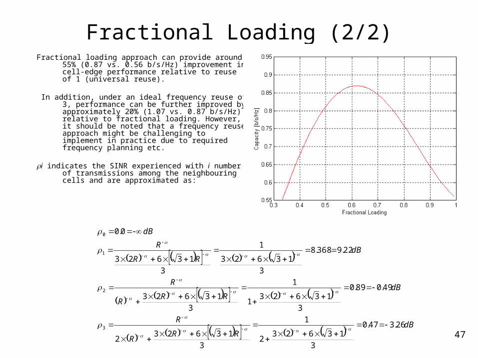
Fractional Loading (2/2)Fractional loading approach can provide around 55%
(0.87 vs. 0.56 b/s/Hz) improvement in cell-edge performance relative to reuse of 1 (universal reuse).
In addition, under an ideal frequency reuse of 3, performance can be further improved by approximately 20% (1.07 vs. 0.87 b/s/Hz) relative to fractional loading. However, it should be noted that a frequency reuse approach might be challenging to implement in practice due to required frequency planning etc.
i indicates the SINR experienced with i number of transmissions among the neighbouring cells and are approximated as:
dBRR
R
R
dBRR
R
R
dBRR
R
dB
26.347.0
3
136232
1
3
136232
49.089.0
3
136231
1
3
13623
22.9368.8
3
13623
1
3
13623
0.0
3
2
1
0
48
Interference Suppression/Cancellation
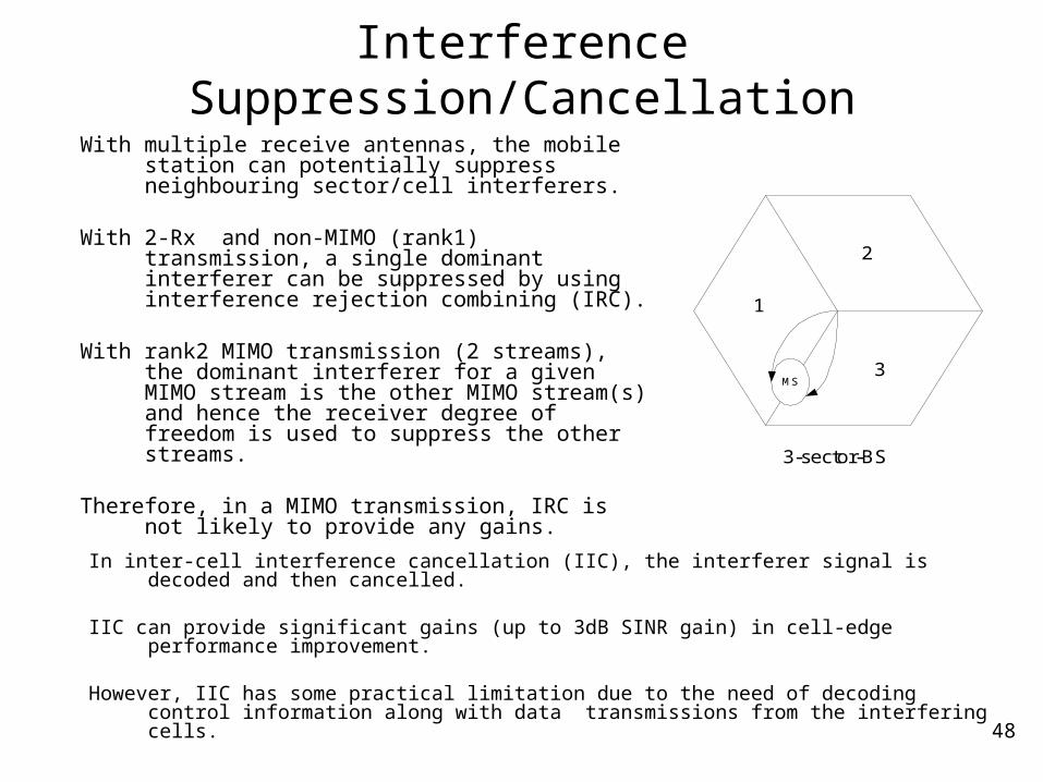
With multiple receive antennas, the mobile station can potentially suppress neighbouring sector/cell interferers.
With 2-Rx and non-MIMO (rank1) transmission, a single dominant interferer can be suppressed by using interference rejection combining (IRC).
With rank2 MIMO transmission (2 streams), the dominant interferer for a given MIMO stream is the other MIMO stream(s) and hence the receiver degree of freedom is used to suppress the other streams.
Therefore, in a MIMO transmission, IRC is not likely to provide any gains.
3-sector-BS
1
MS
2
3
In inter-cell interference cancellation (IIC), the interferer signal is decoded and then cancelled.
IIC can provide significant gains (up to 3dB SINR gain) in cell-edge performance improvement.
However, IIC has some practical limitation due to the need of decoding control information along with data transmissions from the interfering cells.
49
Multimedia Broadcast and Multicast Service
50
Single-Frequency Network (SFN)
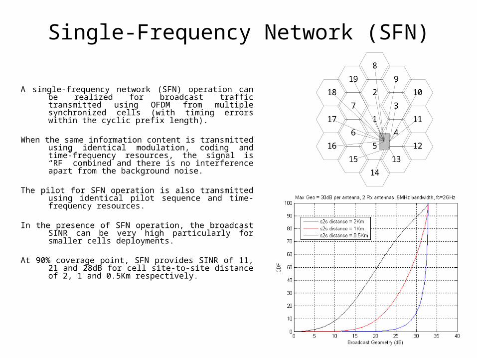
A single-frequency network (SFN) operation can be realized for broadcast traffic transmitted using OFDM from multiple synchronized cells (with timing errors within the cyclic prefix length).
When the same information content is transmitted using identical modulation, coding and time-frequency resources, the signal is “RF” combined and there is no interference apart from the background noise.
The pilot for SFN operation is also transmitted using identical pilot sequence and time-frequency resources.
In the presence of SFN operation, the broadcast SINR can be very high particularly for smaller cells deployments.
At 90% coverage point, SFN provides SINR of 11, 21 and 28dB for cell site-to-site distance of 2, 1 and 0.5Km respectively.
3
1
2
7
17
18 10
19
8
9
4
5
6
11
14
16
13
12
15
51
SFN vs. WCDMA for Broadcast
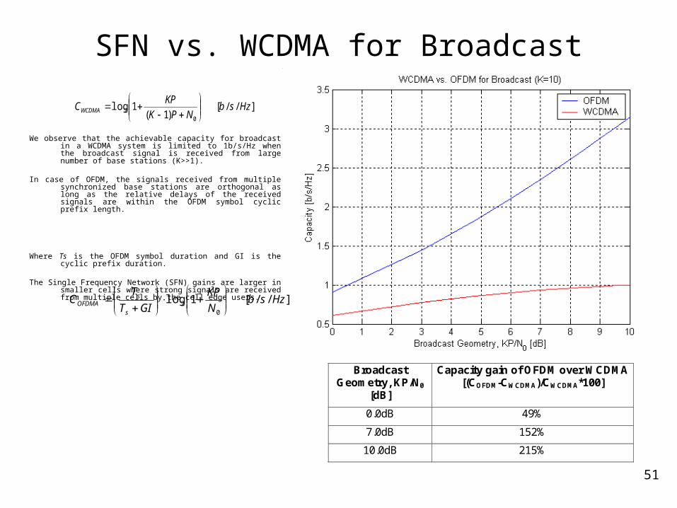
We observe that the achievable capacity for broadcast in a WCDMA system is limited to 1b/s/Hz when the broadcast signal is received from large number of base stations (K>>1).
In case of OFDM, the signals received from multiple synchronized base stations are orthogonal as long as the relative delays of the received signals are within the OFDM symbol cyclic prefix length.
Where Ts is the OFDM symbol duration and GI is the cyclic prefix duration.
The Single Frequency Network (SFN) gains are larger in smaller cells where strong signals are received from multiple cells by the cell edge users.
]//[)1(
1log0
2 HzsbNPK
KPCWCDMA
]//[1log0
2 HzsbN
KP
GIT
TC
s
sOFDMA
Broadcast Geometry, KP/N0
[dB]
Capacity gain of OFDM over WCDMA [(COFDM-CWCDMA)/CWCDMA*100]
0.0dB 49%
7.0dB 152%
10.0dB 215%
52
Layered QoS via Hierarchical Modulation
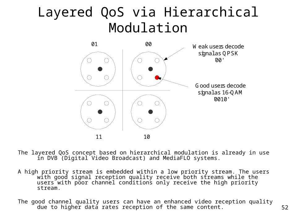
The layered QoS concept based on hierarchical modulation is already in use in DVB (Digital Video Broadcast) and MediaFLO systems.
A high priority stream is embedded within a low priority stream. The users with good signal reception quality receive both streams while the users with poor channel conditions only receive the high priority stream.
The good channel quality users can have an enhanced video reception quality due to higher data rates reception of the same content.
Weak users decodesignal as QPSK
'00'
Good users decodesignal as 16-QAM
'0010'
10
01 00
11
53
Broadcast/Unicast Multiplexing
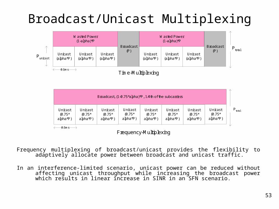
Frequency multiplexing of broadcast/unicast provides the flexibility to adaptively allocate power between broadcast and unicast traffic.
In an interference-limited scenario, unicast power can be reduced without affecting unicast throughput while increasing the broadcast power which results in linear increase in SINR in an SFN scenario.
Unicast(alpha*P)
0.5ms
Unicast(alpha*P)
Unicast(alpha*P)
Broadcast(P)
Unicast(alpha*P)
Unicast(alpha*P)
Unicast(alpha*P)
Broadcast(P)
Wasted Power(1-alpha)*P
Wasted Power(1-alpha)*P
Ptotal
Unicast(0.75*
alpha*P)
0.5ms
Unicast(0.75*
alpha*P)
Unicast(0.75*
alpha*P)
Unicast(0.75*
alpha*P)
Unicast(0.75*
alpha*P)
Unicast(0.75*
alpha*P)
Broadcast, (1-0.75*alpha)*P, 1/4th of the subcarriers
Unicast(0.75*
alpha*P)
Unicast(0.75*
alpha*P)
Frequency-Multiplexing
Time-Multiplexing
Ptotal
Punicast
54
Broadcast/Unicast Multiplexing
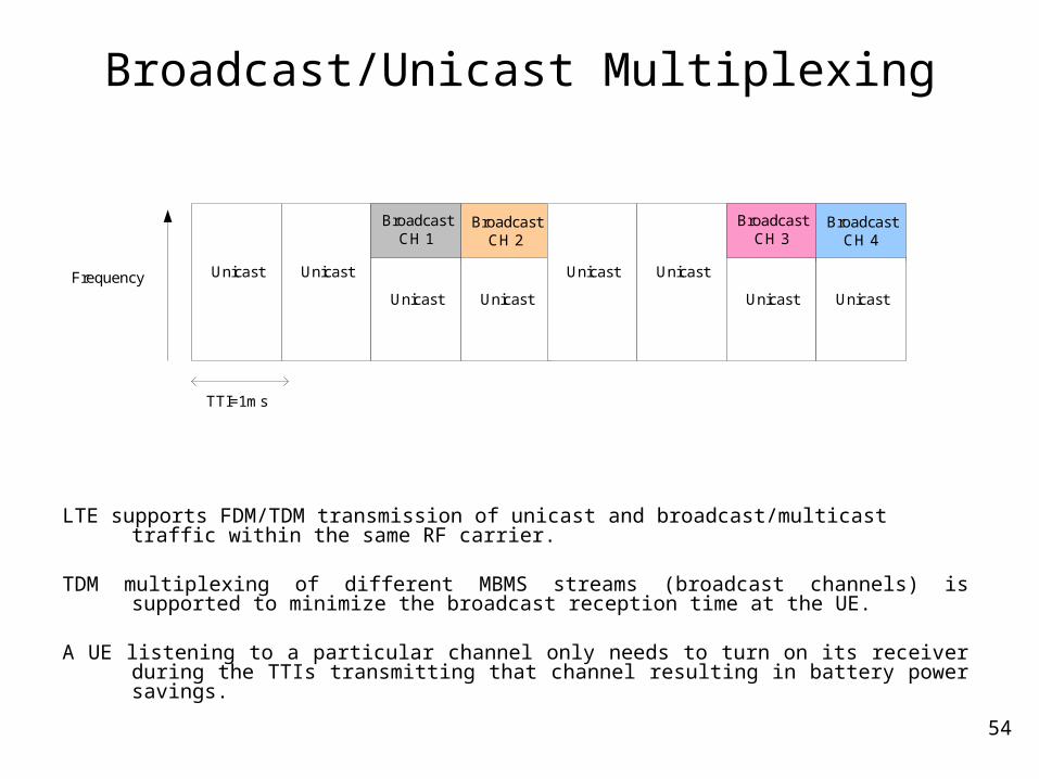
LTE supports FDM/TDM transmission of unicast and broadcast/multicast traffic within the same RF carrier.
TDM multiplexing of different MBMS streams (broadcast channels) is supported to minimize the broadcast reception time at the UE.
A UE listening to a particular channel only needs to turn on its receiver during the TTIs transmitting that channel resulting in battery power savings.
Unicast Unicast
Unicast
BroadcastCH 2
Unicast
Unicast Unicast
TTI=1ms
BroadcastCH 1
Unicast
BroadcastCH 4
Unicast
BroadcastCH 3
Frequency
55
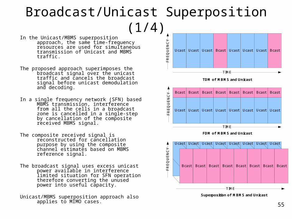
Broadcast/Unicast Superposition (1/4)In the Unicast/MBMS superposition approach,
the same time-frequency resources are used for simultaneous transmission of Unicast and MBMS traffic.
The proposed approach superimposes the broadcast signal over the unicast traffic and cancels the broadcast signal before unicast demodulation and decoding.
In a single frequency network (SFN) based MBMS transmission, interference from all the cells in a broadcast zone is cancelled in a single-step by cancellation of the composite received MBMS signal.
The composite received signal is reconstructed for cancellation purpose by using the composite channel estimates based on MBMS reference signal.
The broadcast signal uses excess unicast power available in interference limited situation for SFN operation therefore converting the unused power into useful capacity.
Unicast/MBMS superposition approach also applies to MIMO cases.
Ucast
TDM of MBMS and Unicast
Ucast Ucast Bcast Ucast Ucast Ucast Bcast
Ucast
Bcast
Ucast
Bcast
Ucast
Bcast
Ucast
Bcast
Ucast
Bcast
Ucast
Bcast
Ucast
Bcast
Ucast
Bcast
TIME
FR
EQ
UE
NC
Y
TIME
FR
EQ
UE
NC
Y
FDM of MBMS and Unicast
Ucast
Superposition of MBMS and Unicast
Ucast Ucast Ucast Ucast Ucast Ucast Ucast
TIME
FR
EQ
UE
NC
YBcast Bcast Bcast Bcast Bcast Bcast Bcast Bcast

56
Broadcast/Unicast Superposition (2/4)
57
1
6
4
3
2
57
1
6
4
3
2
+ =57
1
6
4
3
2
57
1
6
4
3
2
Broadcast(Same content in cells within
a broadcast zone)
Unicast(different contentin different cells)
Broadcast/Unicast
Superposition
57
1
6
4
3
2
57
1
6
4
3
2
- =57
1
6
4
3
2
57
1
6
4
3
2
Decode andCancel
BroadcastUnicast Signal
Broadcast/UnicastSuperimposed Received
Signal
Superposition at BS
Interference Cancellation at MS
57
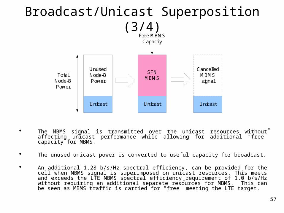
Broadcast/Unicast Superposition (3/4)
The MBMS signal is transmitted over the unicast resources without affecting unicast performance while allowing for additional “free” capacity for MBMS.
The unused unicast power is converted to useful capacity for broadcast.
An additional 1.28 b/s/Hz spectral efficiency, can be provided for the cell when MBMS signal is superimposed on unicast resources. This meets and exceeds the LTE MBMS spectral efficiency requirement of 1.0 b/s/Hz without requiring an additional separate resources for MBMS. This can be seen as MBMS traffic is carried for “free” meeting the LTE target.
Free MBMSCapacity
UnusedNode-BPower
Unicast
SFNMBMS
Unicast Unicast
CancelledMBMSsignal
TotalNode-BPower
58
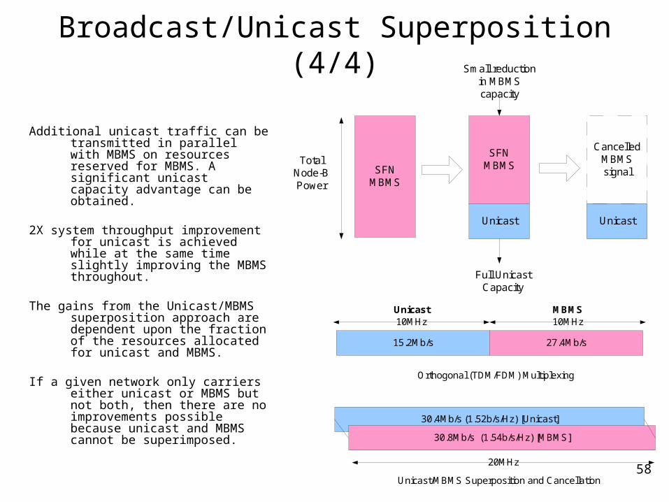
Broadcast/Unicast Superposition (4/4)
Additional unicast traffic can be transmitted in parallel with MBMS on resources reserved for MBMS. A significant unicast capacity advantage can be obtained.
2X system throughput improvement for unicast is achieved while at the same time slightly improving the MBMS throughout.
The gains from the Unicast/MBMS superposition approach are dependent upon the fraction of the resources allocated for unicast and MBMS.
If a given network only carriers either unicast or MBMS but not both, then there are no improvements possible because unicast and MBMS cannot be superimposed.
Full UnicastCapacity
SFNMBMS
SFNMBMS
Unicast Unicast
CancelledMBMSsignal
Small reductionin MBMScapacity
TotalNode-BPower
Unicast
15.2Mb/s 27.4Mb/s
MBMS10MHz 10MHz
30.4Mb/s (1.52b/s/Hz) [Unicast]
30.8Mb/s (1.54b/s/Hz) [MBMS]
20MHz
Orthogonal (TDM/FDM) Multiplexing
Unicast/MBMS Superposition and Cancellation
59
MIMO Techniques
60
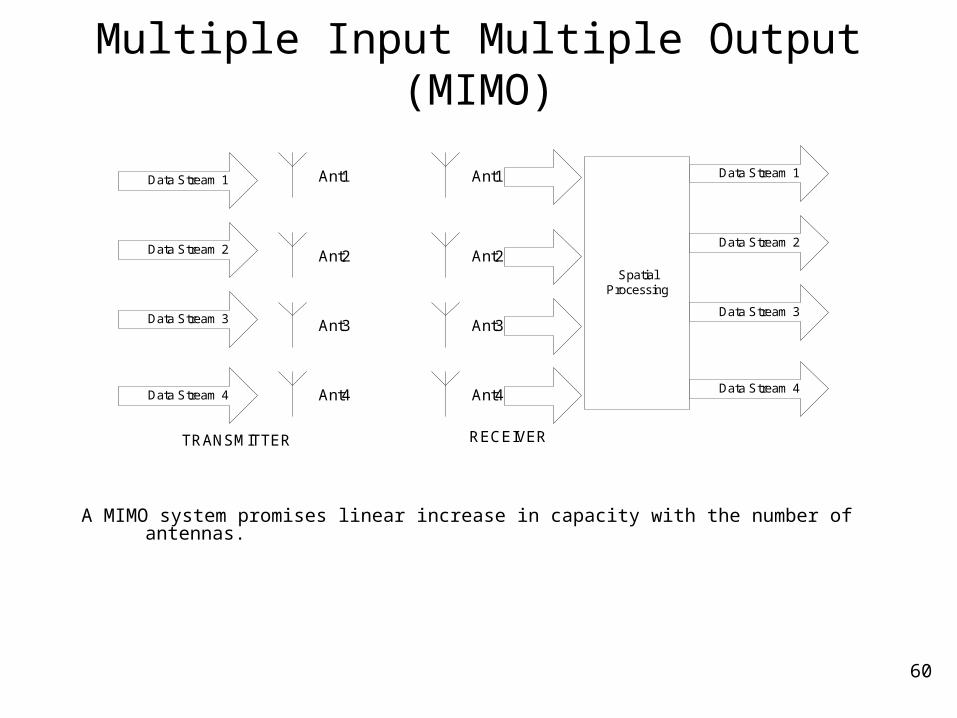
Multiple Input Multiple Output (MIMO)
A MIMO system promises linear increase in capacity with the number of antennas.
Ant1
TRANSMITTER
Data Stream 1
Data Stream 2
Data Stream 3
Data Stream 4
Ant2
Ant3
Ant4
Ant1
Ant2
Ant3
Ant4
SpatialProcessing
RECEIVER
Data Stream 1
Data Stream 2
Data Stream 3
Data Stream 4

61
MIMO Capacity at Low SNR
The capacity of an MxM MIMO channel can be written as:
Where SNR is the received signal-to-noise ratio at each receive antenna.
At low SNR, an MxM system yields a power gain of M relative to a single-receive antenna case because the receive antennas can coherently combine their received signals to get a power boost.
]//[detlog *2 HzsbHH
M
SNRIEC MMIMO
]//[1log1
22 Hzsb
M
SNREC
M
iiMIMO
min21
HzsbeSNRM
HzsbehEM
SNR
HzsbeHHTrEM
SNR
eEM
SNRC
jiji
M
iiMIMO
//log
//log
//log
log
2
2,
2
'
2*
12
2
exx 22 log.1log
Source: “Fundamentals of Wireless Communication” by D. Tse and P. Viswanath
62
MIMO Capacity at High SNR
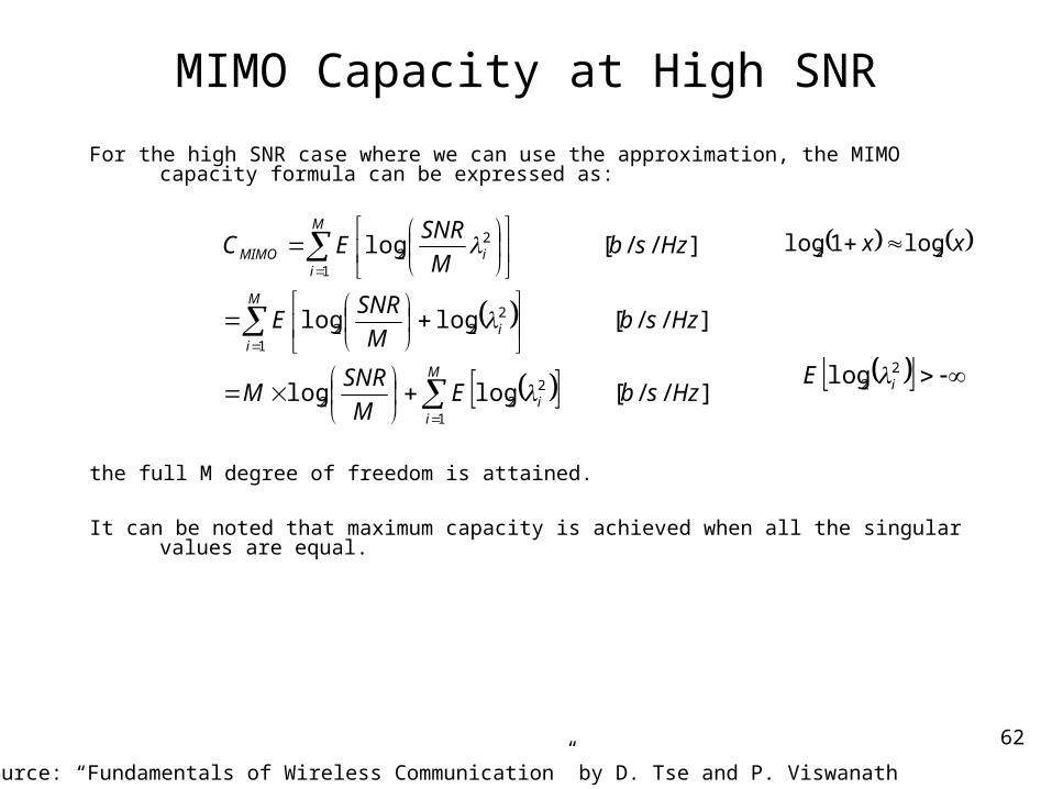
For the high SNR case where we can use the approximation, the MIMO capacity formula can be expressed as:
the full M degree of freedom is attained. It can be noted that maximum capacity is achieved when all the singular values are equal.
M
ii
M
ii
M
iiMIMO
HzsbEM
SNRM
HzsbM
SNRE
HzsbM
SNREC
1
222
1
222
1
22
]//[loglog
]//[loglog
]//[log
xx 22 log1log
22log iE
Source: “Fundamentals of Wireless Communication” by D. Tse and P. Viswanath
63
MIMO Rank Adaptation
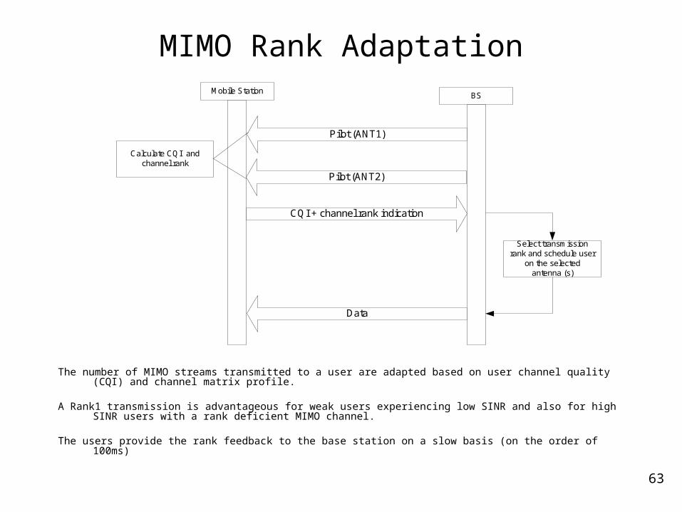
The number of MIMO streams transmitted to a user are adapted based on user channel quality (CQI) and channel matrix profile.
A Rank1 transmission is advantageous for weak users experiencing low SINR and also for high SINR users with a rank deficient MIMO channel.
The users provide the rank feedback to the base station on a slow basis (on the order of 100ms)
Mobile StationBS
Pilot (ANT1)
CQI + channel rank indication
Data
Calculate CQI andchannel rank
Pilot (ANT2)
Select transmissionrank and schedule user
on the selectedantenna (s)
64
MIMO Pre-coding
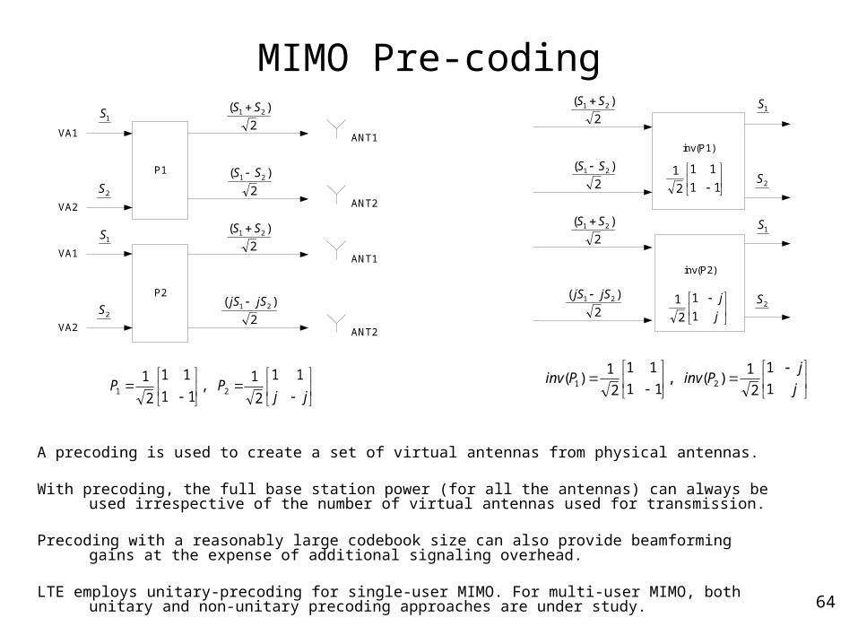
A precoding is used to create a set of virtual antennas from physical antennas.
With precoding, the full base station power (for all the antennas) can always be used irrespective of the number of virtual antennas used for transmission.
Precoding with a reasonably large codebook size can also provide beamforming gains at the expense of additional signaling overhead.
LTE employs unitary-precoding for single-user MIMO. For multi-user MIMO, both unitary and non-unitary precoding approaches are under study.
P1
ANT1
P2
2
)( 21 SS
ANT22
)( 21 SS
ANT12
)( 21 SS
ANT22
)( 21 jSjS
1S
2S
1S
2S
VA1
VA1
VA2
VA2
jj
PP11
2
1,
11
11
2
121
inv(P1)
inv(P2)
2
)( 21 SS
2
)( 21 SS
2
)( 21 SS
2
)( 21 jSjS
1S
2S
1S
2S
11
11
2
1
j
j
1
1
2
1
j
jPinvPinv
1
1
2
1)(,
11
11
2
1)( 21
65
Single-user vs. Multi-user MIMO
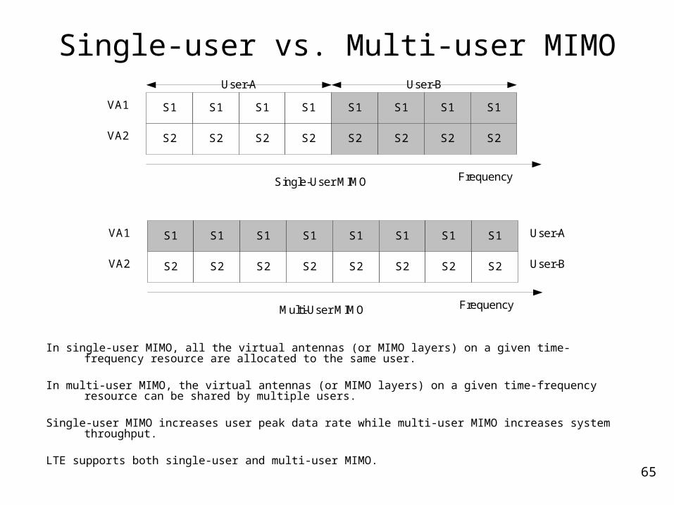
In single-user MIMO, all the virtual antennas (or MIMO layers) on a given time-frequency resource are allocated to the same user.
In multi-user MIMO, the virtual antennas (or MIMO layers) on a given time-frequency resource can be shared by multiple users.
Single-user MIMO increases user peak data rate while multi-user MIMO increases system throughput.
LTE supports both single-user and multi-user MIMO.
FrequencySingle-User MIMO
S2
S1VA1
VA2 S2
S1
S2
S1
S2
S1
S2
S1
S2
S1
S2
S1
S2
S1
FrequencyMulti-User MIMO
S2
S1VA1
VA2 S2
S1
S2
S1
S2
S1
S2
S1
S2
S1
S2
S1
S2
S1
User-A User-B
User-A
User-B
66
SCW vs. MCW MIMO
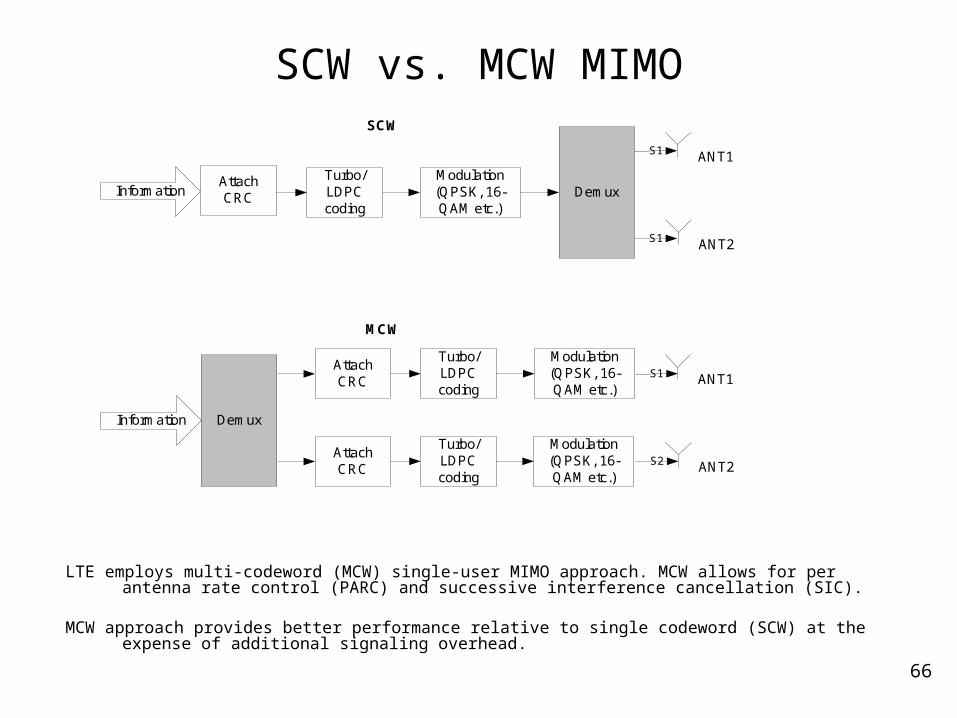
LTE employs multi-codeword (MCW) single-user MIMO approach. MCW allows for per antenna rate control (PARC) and successive interference cancellation (SIC).
MCW approach provides better performance relative to single codeword (SCW) at the expense of additional signaling overhead.
InformationTurbo/LDPCcoding
Modulation(QPSK, 16-QAM etc.)
AttachCRC
ANT1
ANT2
Demux
DemuxInformation
Turbo/LDPCcoding
Turbo/LDPCcoding
Modulation(QPSK, 16-QAM etc.)
Modulation(QPSK, 16-QAM etc.)
AttachCRC
AttachCRC
ANT1
ANT2
S1
S2
S1
S1
SCW
MCW
67
SIC Receiver for Single-user MIMO
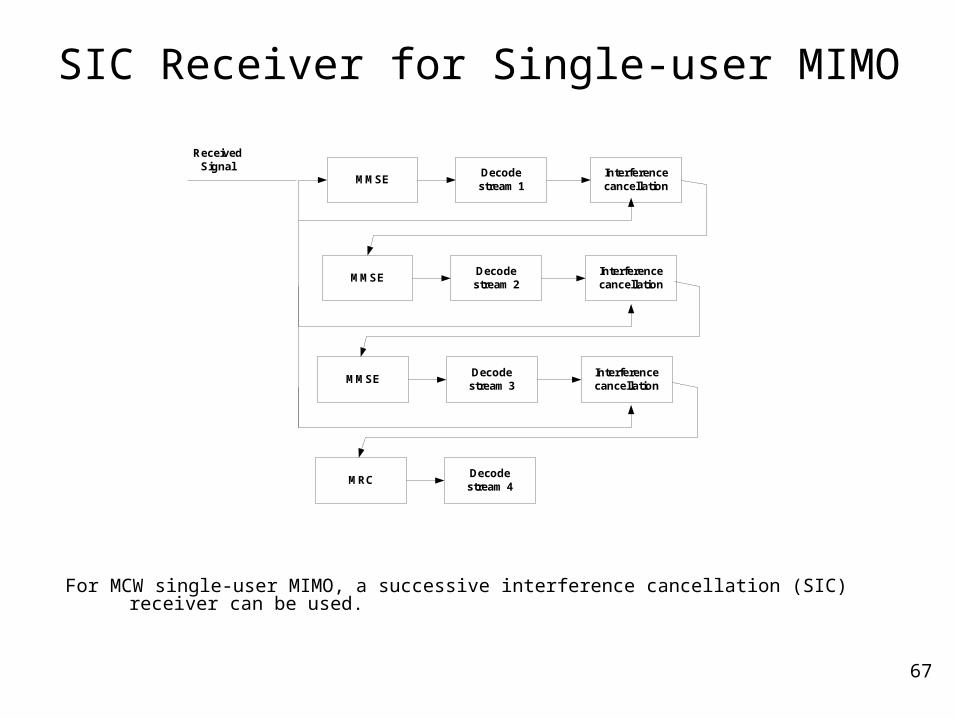
For MCW single-user MIMO, a successive interference cancellation (SIC) receiver can be used.
Decodestream 1
Interferencecancellation
MMSE
Decodestream 2
Interferencecancellation
MMSE
Decodestream 3
Interferencecancellation
MMSE
Decodestream 4
MRC
ReceivedSignal
68
Multi-user MIMO (1/2)
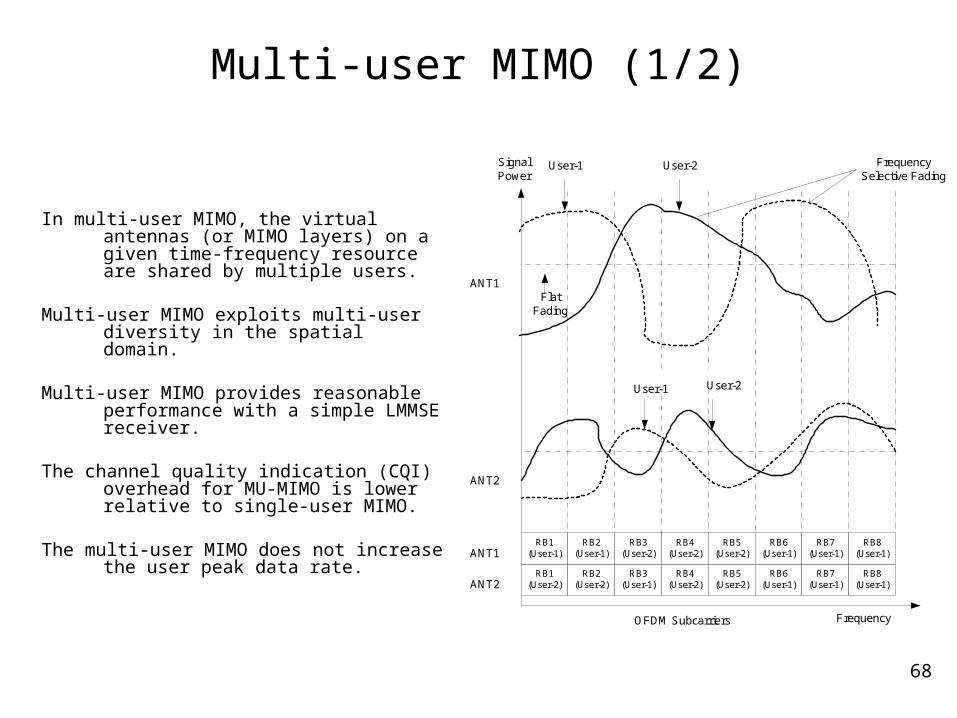
In multi-user MIMO, the virtual antennas (or MIMO layers) on a given time-frequency resource are shared by multiple users.
Multi-user MIMO exploits multi-user diversity in the spatial domain.
Multi-user MIMO provides reasonable performance with a simple LMMSE receiver.
The channel quality indication (CQI) overhead for MU-MIMO is lower relative to single-user MIMO.
The multi-user MIMO does not increase the user peak data rate.
FrequencyOFDM Subcarriers
FlatFading
User-1SignalPower
User-2 FrequencySelective Fading
RB1(User-2)
RB1(User-1)
ANT1
ANT2
ANT1
ANT2RB2
(User-2)
RB2(User-1)
RB3(User-1)
RB3(User-2)
RB4(User-2)
RB4(User-2)
RB5(User-2)
RB5(User-2)
RB6(User-1)
RB6(User-1)
RB7(User-1)
RB7(User-1)
RB8(User-1)
RB8(User-1)
User-1 User-2
69
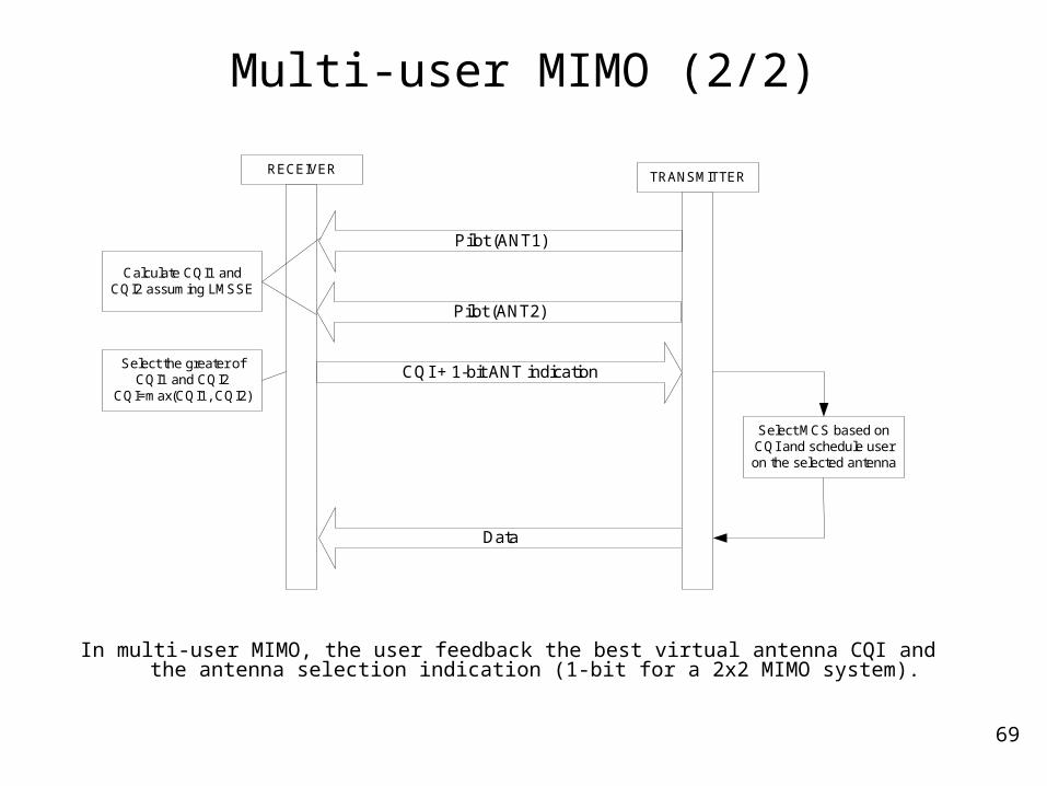
Multi-user MIMO (2/2)
In multi-user MIMO, the user feedback the best virtual antenna CQI and the antenna selection indication (1-bit for a 2x2 MIMO system).
RECEIVERTRANSMITTER
Pilot (ANT1)
CQI + 1-bit ANT indication
Data
Select the greater ofCQI1 and CQI2
CQI=max(CQI1, CQI2)
Calculate CQI1 andCQI2 assuming LMSSE
Pilot (ANT2)
Select MCS based onCQI and schedule useron the selected antenna
70
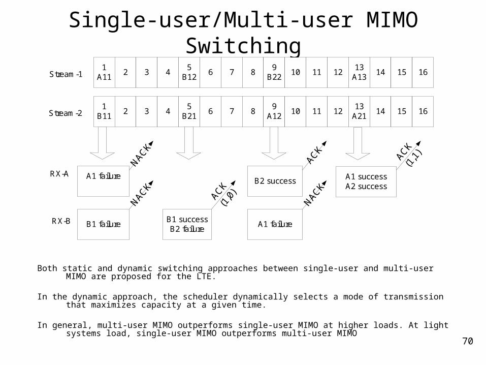
Single-user/Multi-user MIMO Switching
Both static and dynamic switching approaches between single-user and multi-user MIMO are proposed for the LTE.
In the dynamic approach, the scheduler dynamically selects a mode of transmission that maximizes capacity at a given time.
In general, multi-user MIMO outperforms single-user MIMO at higher loads. At light systems load, single-user MIMO outperforms multi-user MIMO
1B11
2 3 45
B216 7 8
9A12
10 11 1213
A2114 15 16
A1 failureB2 success
Stream-1
RX-A A1 successA2 success
NACK
1A11
2 3 45
B126 7 8
9B22
10 11 1213
A1314 15 16
Stream-2
B1 failureB1 successB2 failure
A1 failureRX-B
NACK
NACK
ACK
(1,1
)
ACK
ACK
(1,0
)
71
Transmit Diversity Schemes
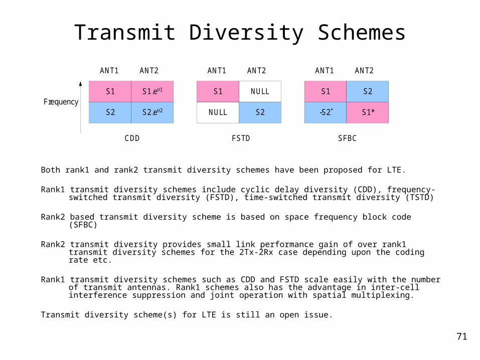
Both rank1 and rank2 transmit diversity schemes have been proposed for LTE.
Rank1 transmit diversity schemes include cyclic delay diversity (CDD), frequency-switched transmit diversity (FSTD), time-switched transmit diversity (TSTD)
Rank2 based transmit diversity scheme is based on space frequency block code (SFBC)
Rank2 transmit diversity provides small link performance gain of over rank1 transmit diversity schemes for the 2Tx-2Rx case depending upon the coding rate etc.
Rank1 transmit diversity schemes such as CDD and FSTD scale easily with the number of transmit antennas. Rank1 schemes also has the advantage in inter-cell interference suppression and joint operation with spatial multiplexing.
Transmit diversity scheme(s) for LTE is still an open issue.
S1
ANT1
S2
S1.e1
S2.e2
ANT2
S1
ANT1
NULL
NULL
S2
ANT2
S1
ANT1
-S2*
S2
S1*
ANT2
CDD FSTD SFBC
Frequency
72
MIMO for Broadcast
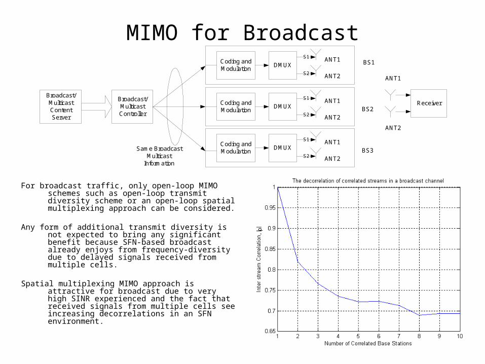
For broadcast traffic, only open-loop MIMO schemes such as open-loop transmit diversity scheme or an open-loop spatial multiplexing approach can be considered.
Any form of additional transmit diversity is not expected to bring any significant benefit because SFN-based broadcast already enjoys from frequency-diversity due to delayed signals received from multiple cells.
Spatial multiplexing MIMO approach is attractive for
broadcast due to very high SINR experienced and the fact that received signals from multiple cells see increasing decorrelations in an SFN environment.
Broadcast/MulticastController
Broadcast/MulticastContentServer
Coding andModulation
DMUXANT1
ANT2
S1
S2
Coding andModulation
DMUXANT1
ANT2
S1
S2
Coding andModulation
DMUXANT1
ANT2
S1
S2BS3
BS1
BS2
Same BroadcastMulticast
Information
Receiver
ANT1
ANT2
73
Flexible Bandwidth Support
74
UE capabilities
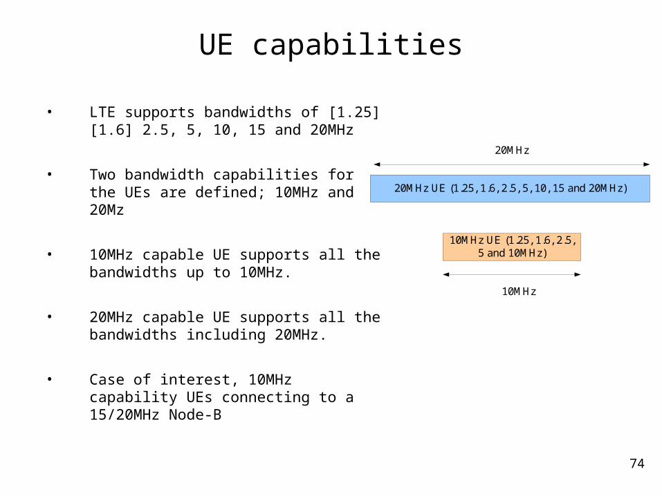
• LTE supports bandwidths of [1.25] [1.6] 2.5, 5, 10, 15 and 20MHz
• Two bandwidth capabilities for the UEs are defined; 10MHz and 20Mz
• 10MHz capable UE supports all the bandwidths up to 10MHz.
• 20MHz capable UE supports all the bandwidths including 20MHz.
• Case of interest, 10MHz capability UEs connecting to a 15/20MHz Node-B
20MHz UE (1.25, 1.6, 2.5, 5, 10, 15 and 20MHz)
10MHz UE (1.25, 1.6, 2.5,5 and 10MHz)
20MHz
10MHz

75
Synchronization Channel
The SCH in the center of the 20 MHz band is used in initial cell search for all the UEs and in neighbor cell search for 20 MHz capability UEs.
The SCHs in the center of the left/right 10 MHz band are used in neighbor cell search for 10 MHz capability UEs.
For bandwidths 1.25, 1.6, 2.5, 5.0 and 10MHz bandwidth, a single 1.25MHz SCH is transmitted at the center frequency.
Both hierarchical and non-hierarchical SCH structures are being considered for LTE.
SCH SCHSCH
RF carrierCenter of the
left useful bandCenter of the
right useful band
1.25 MHz 1.25 MHz1.25 MHz
20 MHz BW
76
Broadcast Channel
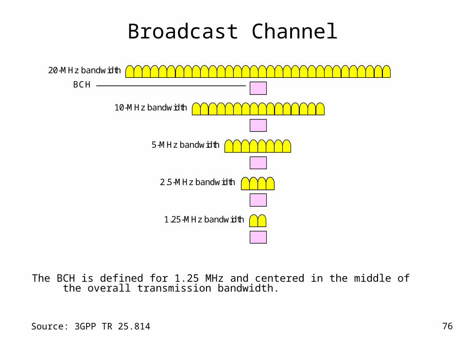
The BCH is defined for 1.25 MHz and centered in the middle of the overall transmission bandwidth.
BCH
10-MHz bandwidth
20-MHz bandwidth
5-MHz bandwidth
1.25-MHz bandwidth
2.5-MHz bandwidth
Source: 3GPP TR 25.814
77
Cell Search
Cell site with 20-MHz transmission bandwidth
SCH
Center carrier frequency
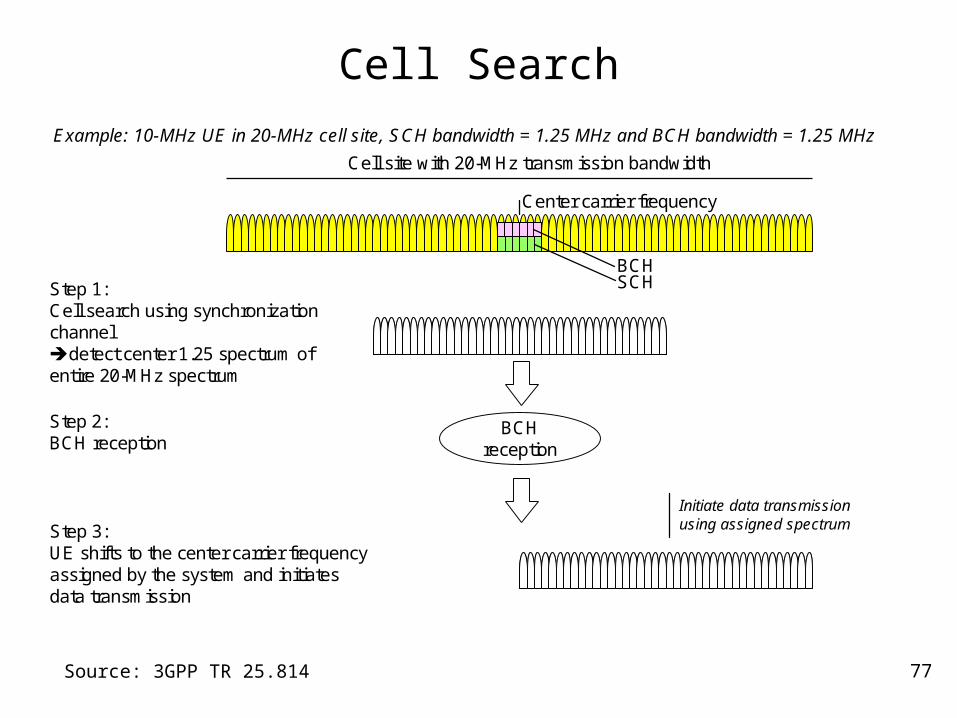
Step 1:Cell search using synchronization channeldetect center 1.25 spectrum of entire 20-MHz spectrum
Example: 10-MHz UE in 20-MHz cell site, SCH bandwidth = 1.25 MHz and BCH bandwidth = 1.25 MHz
Step 2:BCH reception
BCH
BCHreception
Initiate data transmission using assigned spectrumStep 3:
UE shifts to the center carrier frequency assigned by the system and initiates data transmission
Source: 3GPP TR 25.814
78
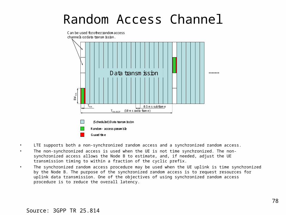
Random Access Channel
• LTE supports both a non-synchronized random access and a synchronized random access.• The non-synchronized access is used when the UE is not time synchronized. The non-synchronized access
allows the Node B to estimate, and, if needed, adjust the UE transmission timing to within a fraction of the cyclic prefix.
• The synchronized random access procedure may be used when the UE uplink is time synchronized by the Node B. The purpose of the synchronized random access is to request resources for uplink data transmission. One of the objectives of using synchronized random access procedure is to reduce the overall latency.
Source: 3GPP TR 25.814
0.5 ms subframeTRA-REP (10 ms radio frame)
TRA
Data transmissionB
WR
A
(Scheduled) Data transmission(Scheduled) Data transmission
Random- access preambleRandom- access preamble
Guard timeGuard time
Can be used for other random- access channels or data transmission.
79
LTE Architecture
80
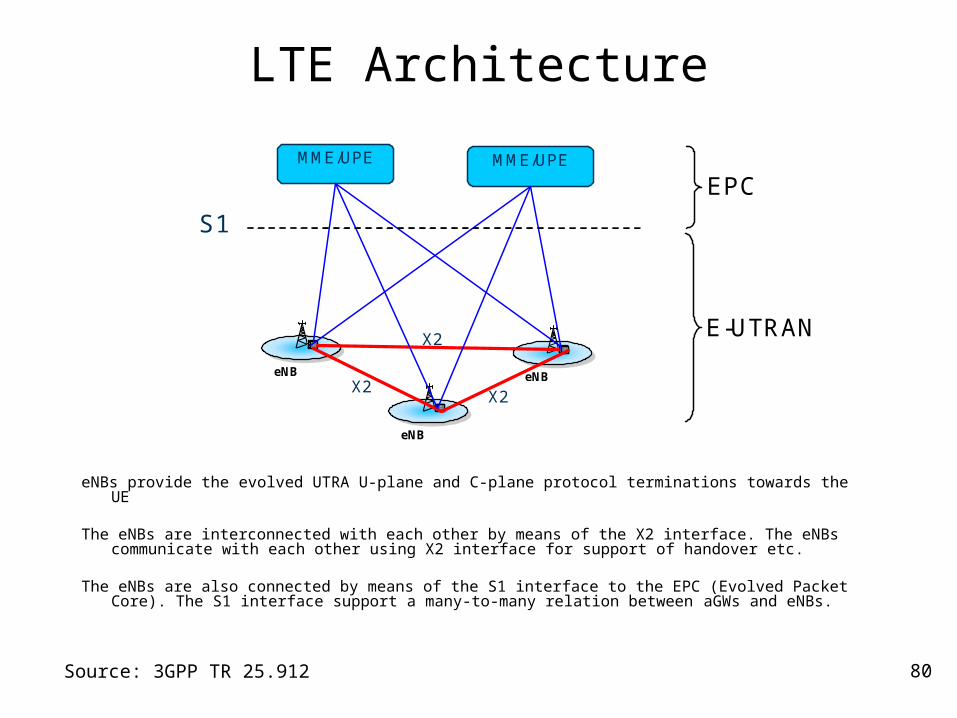
LTE Architecture
eNBs provide the evolved UTRA U-plane and C-plane protocol terminations towards the UE
The eNBs are interconnected with each other by means of the X2 interface. The eNBs communicate with each other using X2 interface for support of handover etc.
The eNBs are also connected by means of the S1 interface to the EPC (Evolved Packet Core). The S1 interface support a many-to-many relation between aGWs and eNBs.
Source: 3GPP TR 25.912
eNB eNB
eNB
MME/UPE MME/UPE
S1
X2
X2
X2
EPC
E-UTRAN
81
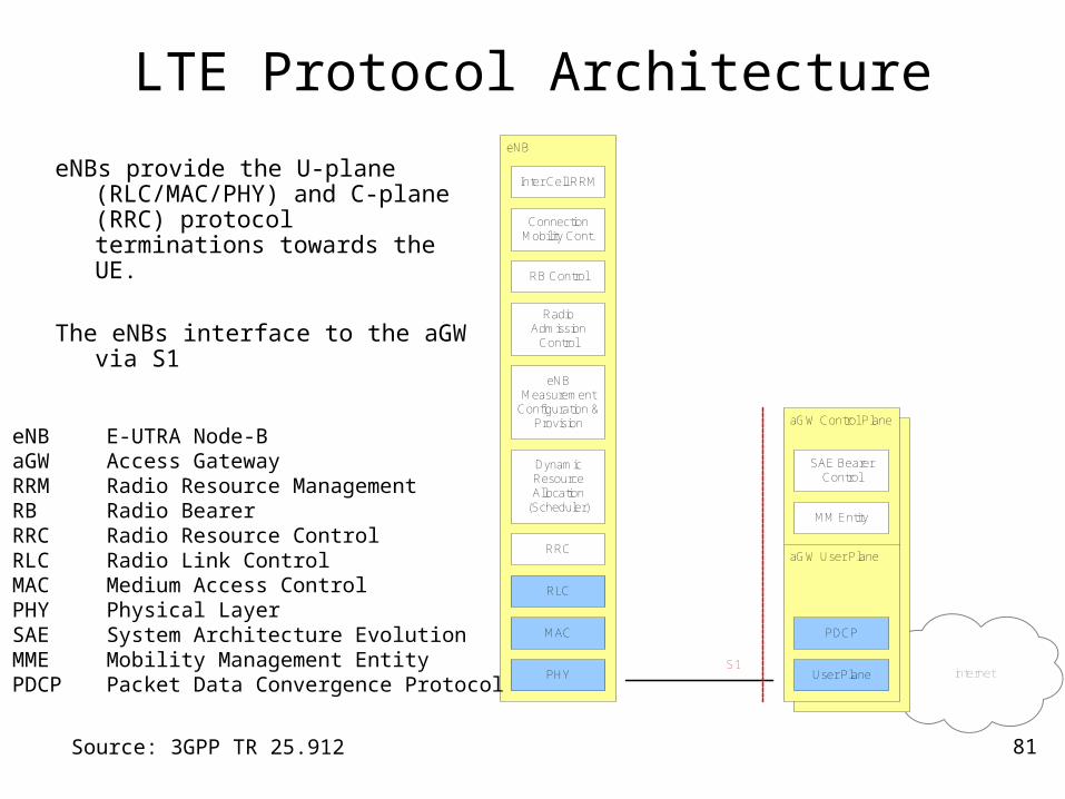
LTE Protocol Architecture
eNBs provide the U-plane (RLC/MAC/PHY) and C-plane (RRC) protocol terminations towards the UE.
The eNBs interface to the aGW via S1
internet
eNB
RB Control
Connection Mobility Cont.
eNBMeasurement
Configuration & Provision
Dynamic Resource Allocation
(Scheduler)
RRC
PHY
aGW Control Plane
aGW User Plane
User Plane
MM Entity
SAE Bearer Control
S1
MAC PDCP
Inter Cell RRM
Radio Admission
Control
RLC
Source: 3GPP TR 25.912
eNB E-UTRA Node-B aGW Access Gateway RRM Radio Resource Management RB Radio Bearer RRC Radio Resource Control RLC Radio Link Control MAC Medium Access Control PHY Physical Layer SAE System Architecture Evolution MME Mobility Management Entity PDCP Packet Data Convergence Protocol
82
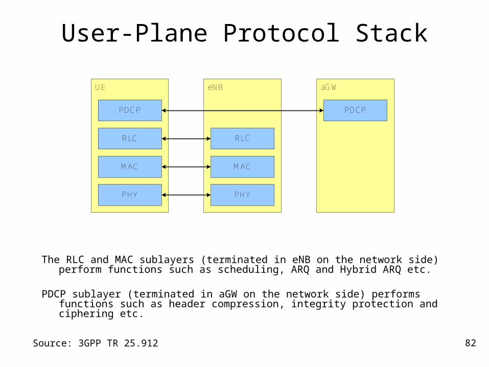
User-Plane Protocol Stack
The RLC and MAC sublayers (terminated in eNB on the network side) perform functions such as scheduling, ARQ and Hybrid ARQ etc.
PDCP sublayer (terminated in aGW on the network side) performs functions such as header compression, integrity protection and ciphering etc.
Source: 3GPP TR 25.912
eNB
PHY
UE
PHY
MAC
RLC
MAC
aGW
PDCPPDCP
RLC
83
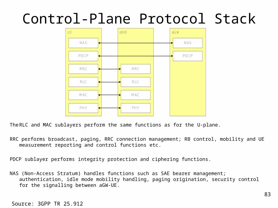
Control-Plane Protocol Stack
The RLC and MAC sublayers perform the same functions as for the U-plane.
RRC performs broadcast, paging, RRC connection management; RB control, mobility and UE measurement reporting and control functions etc.
PDCP sublayer performs integrity protection and ciphering functions.
NAS (Non-Access Stratum) handles functions such as SAE bearer management; authentication, idle mode mobility handling, paging origination, security control for the signalling between aGW-UE.
Source: 3GPP TR 25.912
eNB
PHY
UE
PHY
MAC
RLC
MAC
aGW
RLC
NAS NAS
RRC RRC
PDCP PDCP
84
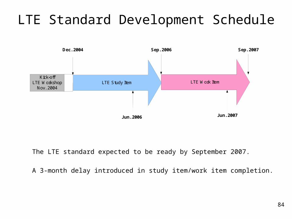
LTE Standard Development Schedule
LTE Study Item LTE Work ItemKick-off
LTE WorkshopNov. 2004
Dec. 2004 Sep. 2006 Sep. 2007
Jun. 2006 Jun. 2007
The LTE standard expected to be ready by September 2007.
A 3-month delay introduced in study item/work item completion.