153867696 lte-tutorial-femtoforum-part2-130814004042-phpapp01
TRANSCRIPT
1Marius Pesavento, Willem Mulder, Femto Forum Plenary, June 2010, Reading, UK © mimoOn
LTE Tutorial part 2 Advanced topics in LTE
Marius Pesavento - [email protected] Mulder - [email protected]
2Marius Pesavento, Willem Mulder, Femto Forum Plenary, June 2010, Reading, UK © mimoOn
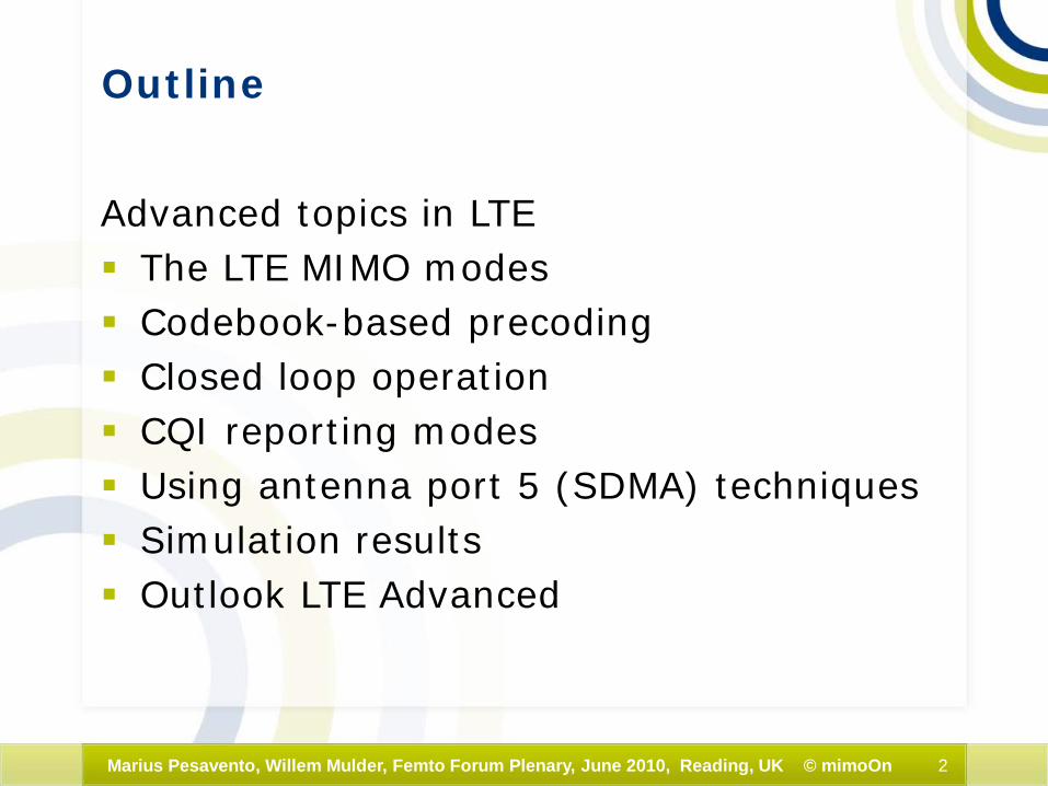
Outline
Advanced topics in LTE The LTE MIMO modes Codebook-based precoding Closed loop operation CQI reporting modes Using antenna port 5 (SDMA) techniques Simulation results Outlook LTE Advanced
3Marius Pesavento, Willem Mulder, Femto Forum Plenary, June 2010, Reading, UK © mimoOn
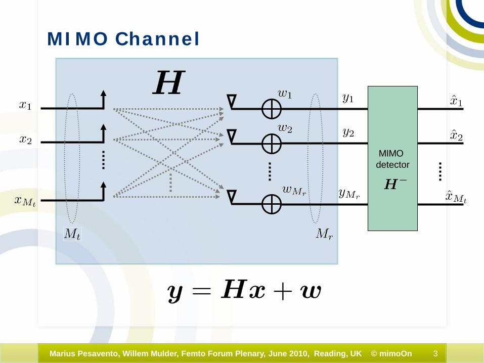
MIMO Channel
MIMO detector
4Marius Pesavento, Willem Mulder, Femto Forum Plenary, June 2010, Reading, UK © mimoOn
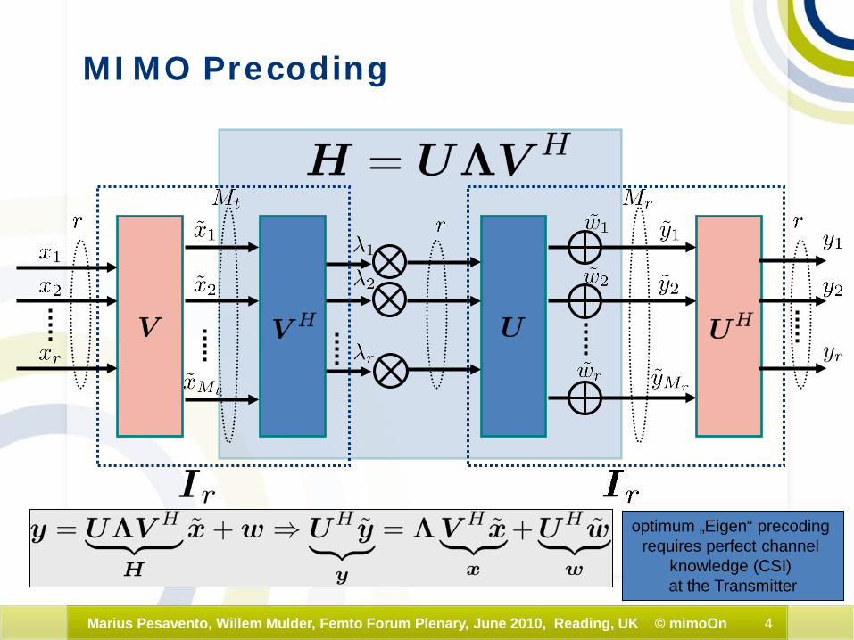
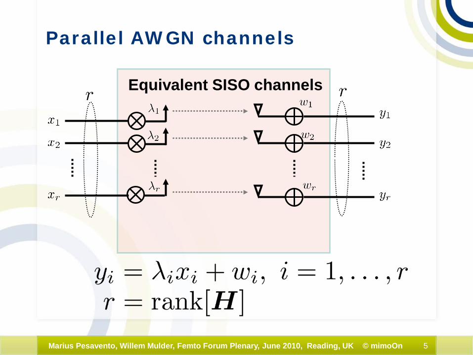
MIMO Precoding
optimum „Eigen“ precoding requires perfect channel
knowledge (CSI) at the Transmitter
5Marius Pesavento, Willem Mulder, Femto Forum Plenary, June 2010, Reading, UK © mimoOn
Parallel AWGN channels
Equivalent SISO channels
6Marius Pesavento, Willem Mulder, Femto Forum Plenary, June 2010, Reading, UK © mimoOn
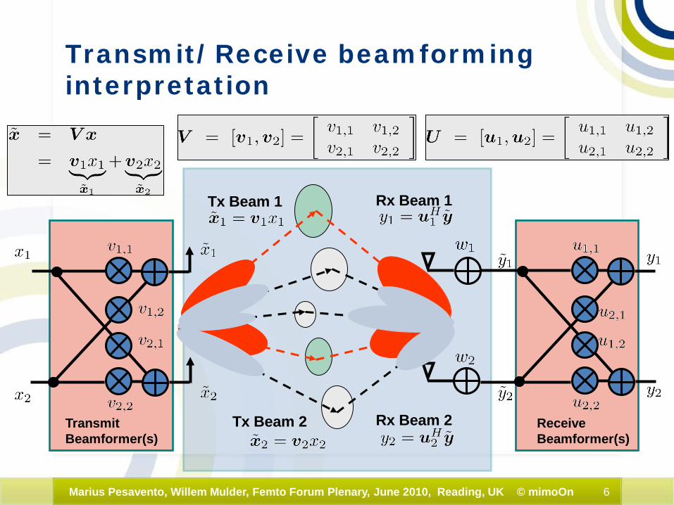
Tx Beam 1
Tx Beam 2
Rx Beam 1
Rx Beam 2TransmitBeamformer(s)
ReceiveBeamformer(s)
Transmit/Receive beamforming interpretation
7Marius Pesavento, Willem Mulder, Femto Forum Plenary, June 2010, Reading, UK © mimoOn
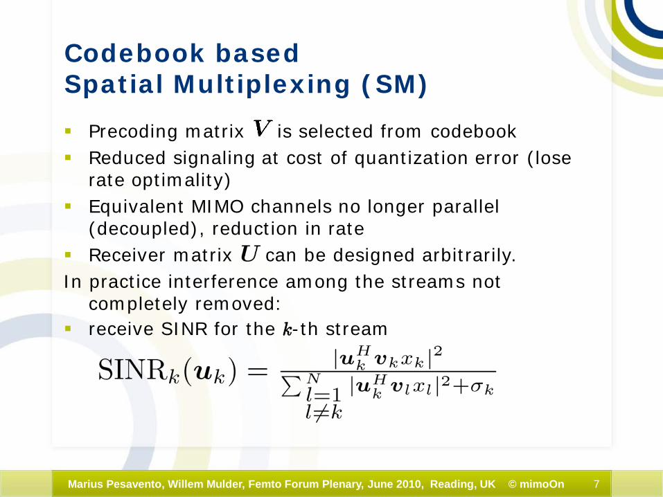
Codebook based Spatial Multiplexing (SM)
Precoding matrix is selected from codebook Reduced signaling at cost of quantization error (lose
rate optimality) Equivalent MIMO channels no longer parallel
(decoupled), reduction in rate Receiver matrix can be designed arbitrarily.In practice interference among the streams not
completely removed: receive SINR for the k-th stream
8Marius Pesavento, Willem Mulder, Femto Forum Plenary, June 2010, Reading, UK © mimoOn
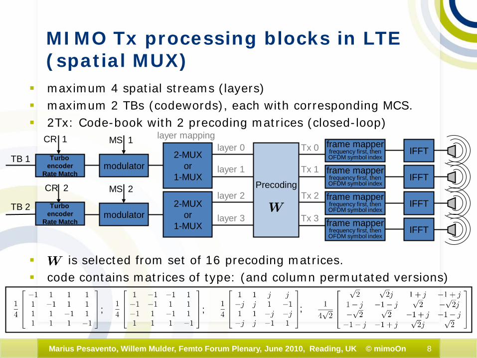
MIMO Tx processing blocks in LTE(spatial MUX)
maximum 4 spatial streams (layers) maximum 2 TBs (codewords), each with corresponding MCS. 2Tx: Code-book with 2 precoding matrices (closed-loop)
is selected from set of 16 precoding matrices. code contains matrices of type: (and column permutated versions)
Turbo encoder
Rate Match
TB 1
TB 2
CR 1
CR 2
modulator
modulator
MS 1
MS 2
2-MUXor
1-MUX
2-MUXor
1-MUX
layer mappinglayer 0
layer 1
layer 2
layer 3
IFFTframe mapperfrequency first, thenOFDM symbol index
Tx 0
Tx 1
Tx 2
Tx 3
IFFTframe mapperfrequency first, thenOFDM symbol index
IFFTframe mapperfrequency first, thenOFDM symbol index
IFFTframe mapperfrequency first, thenOFDM symbol index
Precoding
; ; ;
Turbo encoder
Rate Match
9Marius Pesavento, Willem Mulder, Femto Forum Plenary, June 2010, Reading, UK © mimoOn
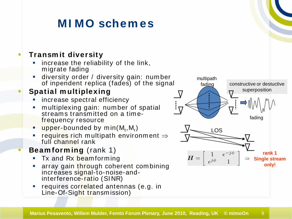
MIMO schemes
Transmit diversity increase the reliability of the link,
migrate fading diversity order / diversity gain: number
of inpendent replica (fades) of the signal Spatial multiplexing
increase spectral efficiency multiplexing gain: number of spatial
streams transmitted on a time-frequency resource
upper-bounded by min(Mt,Mr) requires rich multipath environment ⇒
full channel rank Beamforming (rank 1)
Tx and Rx beamforming array gain through coherent combining
increases signal-to-noise-and-interference-ratio (SINR)
requires correlated antennas (e.g. in Line-Of-Sight transmission)
fading
multipath fading constructive or destuctive
superposition
LOS
⇒rank 1
Single streamonly!

10Marius Pesavento, Willem Mulder, Femto Forum Plenary, June 2010, Reading, UK © mimoOn
DL-MIMO modes in LTE
Single antenna port (no MIMO) Transmit Diversity (TD), space-frequency Alamouti
code Open-loop Spatial Multiplexing (SM) Closed-loop SM Multi-User (MU) MIMO Rank 1 closed-loop SM (compressed control
signaling) Antenna port 5 beamforming, UE specific reference
signals
11Marius Pesavento, Willem Mulder, Femto Forum Plenary, June 2010, Reading, UK © mimoOn
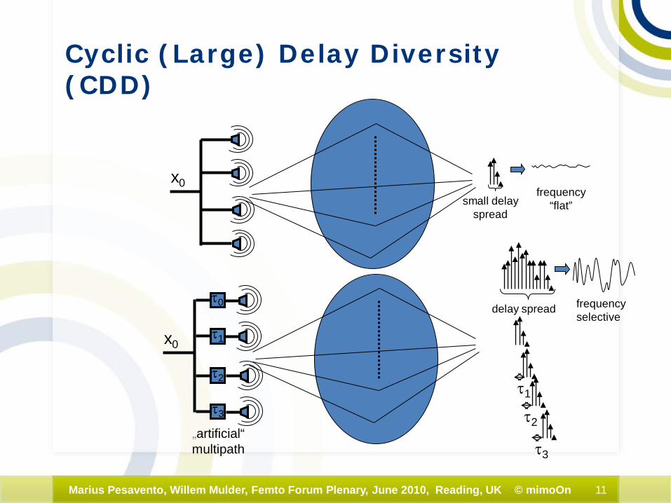
Cyclic (Large) Delay Diversity (CDD)
x0small delay
spread
frequency“flat”
delay spread frequencyselective
τ0
τ3
τ1
τ2
τ3
„artificial“multipath
x0τ1
τ2
12Marius Pesavento, Willem Mulder, Femto Forum Plenary, June 2010, Reading, UK © mimoOn
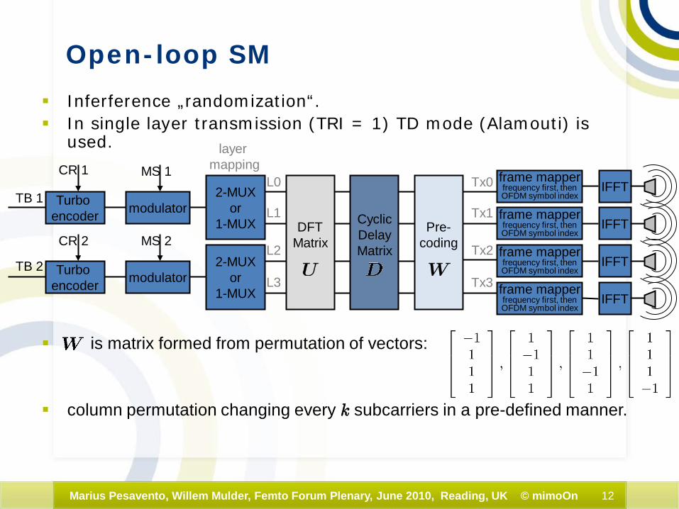
Open-loop SM
Inferference „randomization“. In single layer transmission (TRI = 1) TD mode (Alamouti) is
used.
is matrix formed from permutation of vectors:
column permutation changing every k subcarriers in a pre-defined manner.
TB 1
TB 2
CR 1
CR 2
modulator
modulator
MS 1
MS 2
2-MUXor
1-MUX
2-MUXor
1-MUX
layermapping
L0
L1
L2
L3
IFFTframe mapperfrequency first, thenOFDM symbol index
Tx0
Tx1
Tx2
Tx3
IFFTframe mapperfrequency first, thenOFDM symbol index
IFFTframe mapperfrequency first, thenOFDM symbol index
IFFTframe mapperfrequency first, thenOFDM symbol index
Turbo encoder
Turbo encoder
Pre-coding
DFTMatrix
CyclicDelayMatrix

13Marius Pesavento, Willem Mulder, Femto Forum Plenary, June 2010, Reading, UK © mimoOn
Spatial DiversitySpace-Time-Coding: Alamouti
Symbolmodulator
encoded bitstream
…,b3, b2, b1, b0,...… s1, s0,...
… s*0, -s*1,...… y1, y0,...
h0
h1
… s1, s0,...
spac
e-tim
een
code
r
spac
e-tim
ede
code
r
y*1
y0
equivalent „MIMO“ channel
„MIMO“ equalizer/detector
deco
der
s1
s0
No CSI at the transmitter
required!!!
14Marius Pesavento, Willem Mulder, Femto Forum Plenary, June 2010, Reading, UK © mimoOn
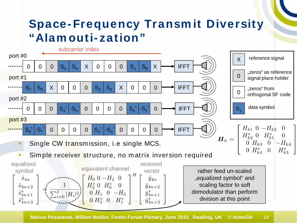
Space-Frequency Transmit Diversity“Alamouti-zation”
Single CW transmission, i.e single MCS.
Simple receiver structure, no matrix inversion required
XS0S10
S2S3
XS50
port #0
0
00
00 0X0X
00
port #1
subcarrier index
port #2
port #3
IFFT
IFFT
IFFT
IFFT
S4
0
0000
00
000
S6S7
0
S4*
-S3*S2
*
-S1*S0
* 0000
-S7*S6
*
-S5*
000
„zeros“ as reference signal place holder
0„zeros“ from orthogonal SF code
X reference signal
S1data symbol
equivalent channelreceived
vectorequalized
symbol rather feed un-scaled „equalized symbol“ and
scaling factor to soft demodulator than perform
division at this point
15Marius Pesavento, Willem Mulder, Femto Forum Plenary, June 2010, Reading, UK © mimoOn
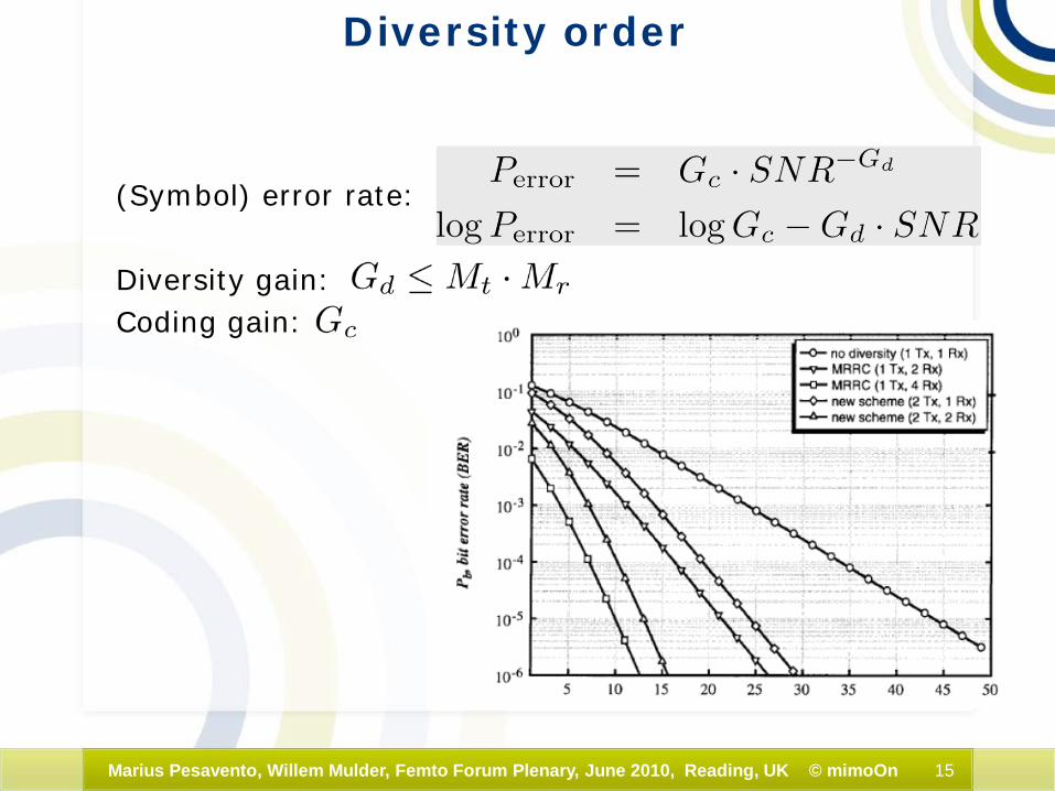
Diversity order
(Symbol) error rate:
Diversity gain:Coding gain:
16Marius Pesavento, Willem Mulder, Femto Forum Plenary, June 2010, Reading, UK © mimoOn
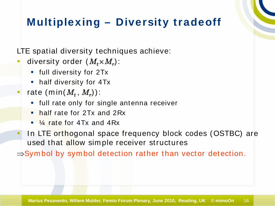
Multiplexing – Diversity tradeoff
LTE spatial diversity techniques achieve: diversity order (Mt£Mr):
full diversity for 2Tx half diversity for 4Tx
rate (min(Mt , Mr)): full rate only for single antenna receiver half rate for 2Tx and 2Rx ¼ rate for 4Tx and 4Rx
In LTE orthogonal space frequency block codes (OSTBC) are used that allow simple receiver structures
⇒Symbol by symbol detection rather than vector detection.
17Marius Pesavento, Willem Mulder, Femto Forum Plenary, June 2010, Reading, UK © mimoOn
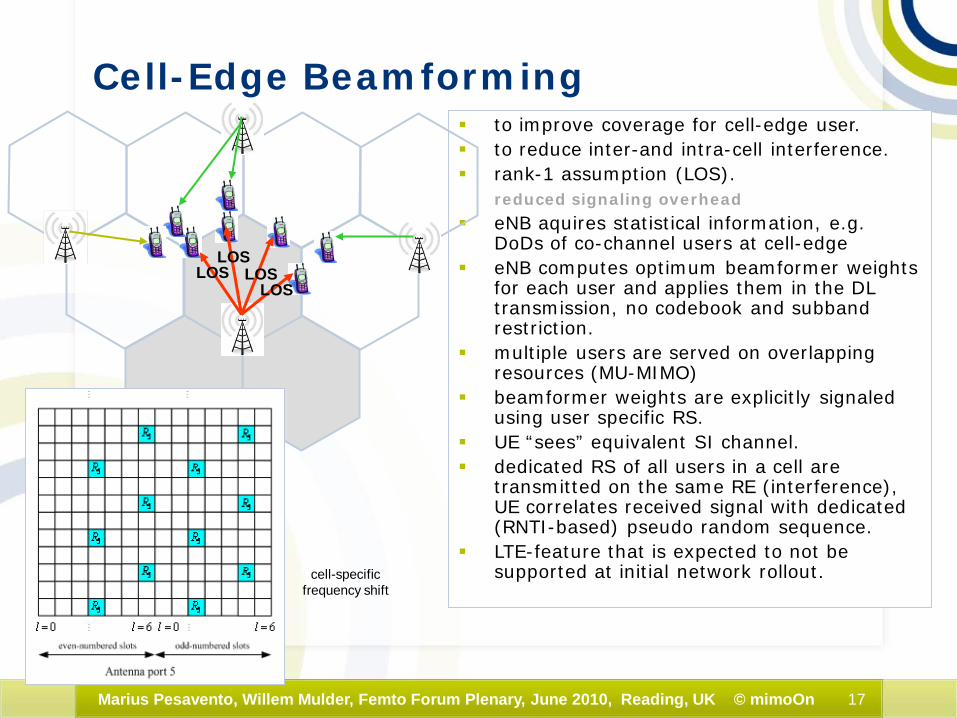
Cell-Edge Beamforming to improve coverage for cell-edge user. to reduce inter-and intra-cell interference. rank-1 assumption (LOS).
reduced signaling overhead
eNB aquires statistical information, e.g. DoDs of co-channel users at cell-edge
eNB computes optimum beamformer weights for each user and applies them in the DL transmission, no codebook and subbandrestriction.
multiple users are served on overlapping resources (MU-MIMO)
beamformer weights are explicitly signaled using user specific RS.
UE “sees” equivalent SI channel. dedicated RS of all users in a cell are
transmitted on the same RE (interference), UE correlates received signal with dedicated (RNTI-based) pseudo random sequence.
LTE-feature that is expected to not be supported at initial network rollout.
LOSLOS
LOSLOS
cell-specific frequency shift
18Marius Pesavento, Willem Mulder, Femto Forum Plenary, June 2010, Reading, UK © mimoOn
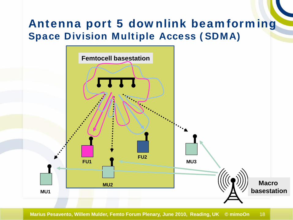
Femtocell basestation
FU1FU2
MU1MU2
MU3
Macro basestation
Antenna port 5 downlink beamforming Space Division Multiple Access (SDMA)
19Marius Pesavento, Willem Mulder, Femto Forum Plenary, June 2010, Reading, UK © mimoOn
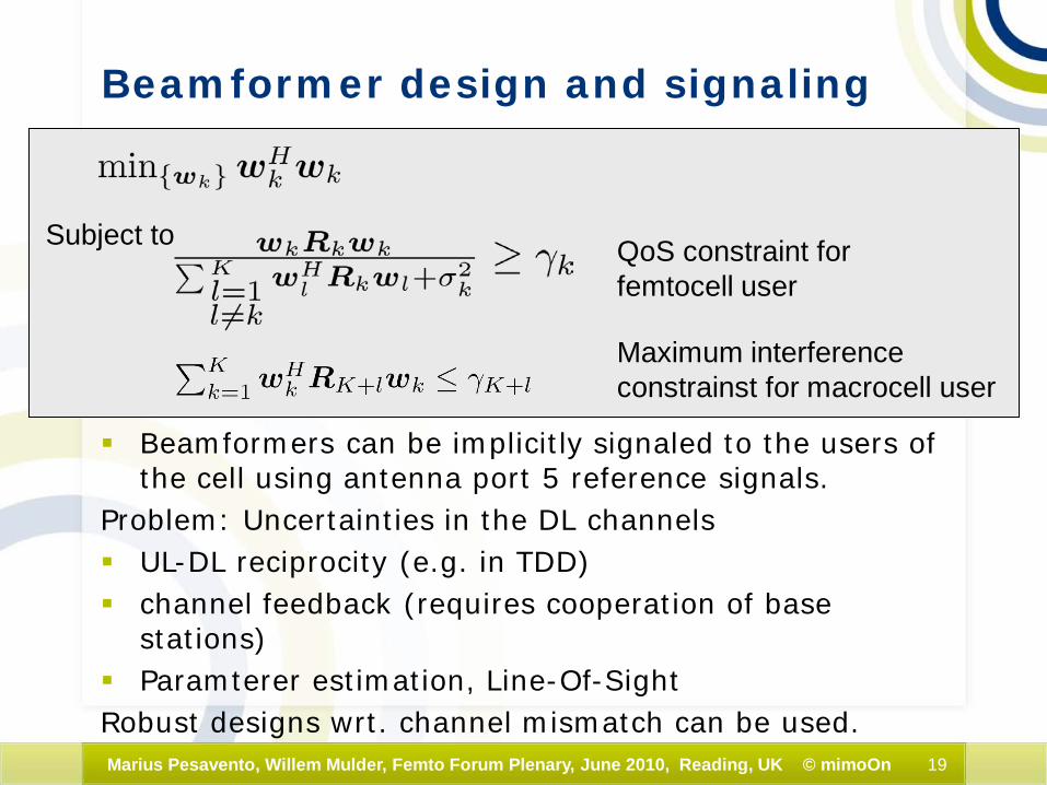
Beamformer design and signaling
Beamformers can be implicitly signaled to the users of the cell using antenna port 5 reference signals.
Problem: Uncertainties in the DL channels UL-DL reciprocity (e.g. in TDD) channel feedback (requires cooperation of base
stations) Paramterer estimation, Line-Of-SightRobust designs wrt. channel mismatch can be used.
Subject to QoS constraint forfemtocell user
Maximum interferenceconstrainst for macrocell user

20Marius Pesavento, Willem Mulder, Femto Forum Plenary, June 2010, Reading, UK © mimoOn
CQI report and 4-bit CQI table
CQIindex
modulation code rate x 1024
efficiency
0 out of range
1 QPSK 78 0.1523
2 QPSK 120 0.2344
3 QPSK 193 0.3770
4 QPSK 308 0.6016
5 QPSK 449 0.8770
6 QPSK 602 1.1758
7 16QAM 378 1.4766
8 16QAM 490 1.9141
9 16QAM 616 2.4063
10 64QAM 466 2.7305
11 64QAM 567 3.3223
12 64QAM 666 3.9023
13 64QAM 772 4.5234
14 64QAM 873 5.1152
15 64QAM 948 5.5547
subband CQI index =differential CQI + wideband CQI index
Differential CQI value Offset level
0 ≤1
1 2
2 3
3 ≥4
Spatial differential CQI value
Offset level
0 0
1 1
2 2
3 ≥3
4 ≤-4
5 -3
6 -2
7 -1
3-bit subband/wideband spatial differential CQI
2-bit subband differential CQI
21Marius Pesavento, Willem Mulder, Femto Forum Plenary, June 2010, Reading, UK © mimoOn
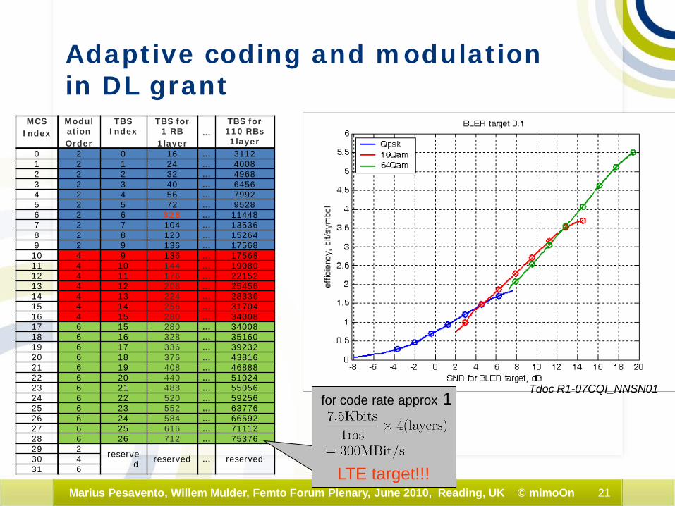
Adaptive coding and modulation in DL grant
Tdoc R1-07CQI_NNSN01
MCSIndex
ModulationOrder
TBS Index
TBS for1 RB
1layer…
TBS for110 RBs 1layer
0 2 0 16 … 31121 2 1 24 … 40082 2 2 32 … 49683 2 3 40 … 64564 2 4 56 … 79925 2 5 72 … 95286 2 6 328 … 114487 2 7 104 … 135368 2 8 120 … 152649 2 9 136 … 1756810 4 9 136 … 1756811 4 10 144 … 1908012 4 11 176 … 2215213 4 12 208 … 2545614 4 13 224 … 2833615 4 14 256 … 3170416 4 15 280 … 3400817 6 15 280 … 3400818 6 16 328 … 3516019 6 17 336 … 3923220 6 18 376 … 4381621 6 19 408 … 4688822 6 20 440 … 5102423 6 21 488 … 5505624 6 22 520 … 5925625 6 23 552 … 6377626 6 24 584 … 6659227 6 25 616 … 7111228 6 26 712 … 7537629 2 reserve
d reserved … reserved30 431 6
for code rate approx 1
LTE target!!!
22Marius Pesavento, Willem Mulder, Femto Forum Plenary, June 2010, Reading, UK © mimoOn
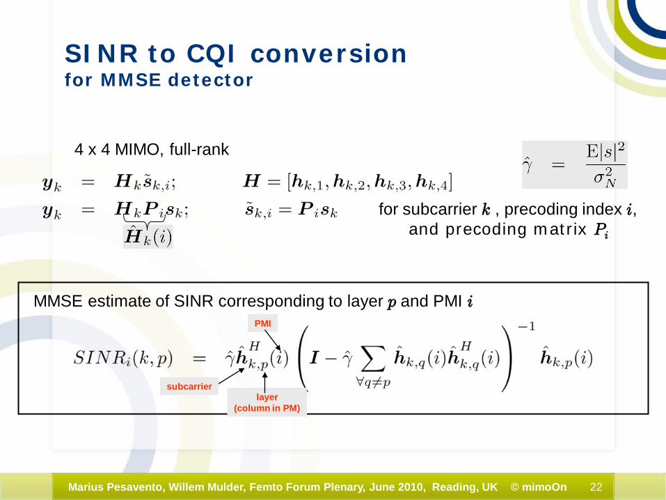
SINR to CQI conversionfor MMSE detector
4 x 4 MIMO, full-rank
for subcarrier k , precoding index i,and precoding matrix Pi
MMSE estimate of SINR corresponding to layer p and PMI i
subcarrierlayer
(column in PM)
PMI
23Marius Pesavento, Willem Mulder, Femto Forum Plenary, June 2010, Reading, UK © mimoOn
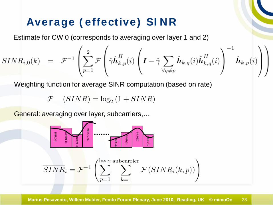
Average (effective) SINREstimate for CW 0 (corresponds to averaging over layer 1 and 2)
Weighting function for average SINR computation (based on rate)
SINR
(2)
SINR
(1)
SINR
(3)
SINR
(4)
SINR
(N-2)
SINI(N
-1)
SINR
(N)
SINR
(N-3)
General: averaging over layer, subcarriers,…
24Marius Pesavento, Willem Mulder, Femto Forum Plenary, June 2010, Reading, UK © mimoOn
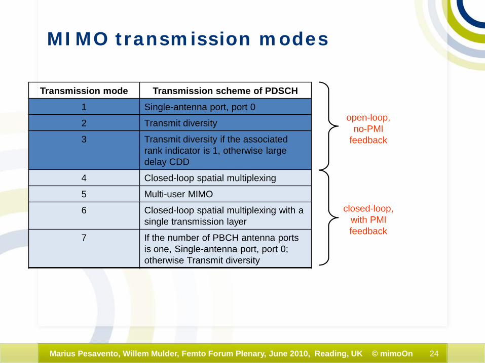
MIMO transmission modes
Transmission mode Transmission scheme of PDSCH1 Single-antenna port, port 0
2 Transmit diversity
3 Transmit diversity if the associated rank indicator is 1, otherwise large delay CDD
4 Closed-loop spatial multiplexing
5 Multi-user MIMO
6 Closed-loop spatial multiplexing with a single transmission layer
7 If the number of PBCH antenna ports is one, Single-antenna port, port 0; otherwise Transmit diversity
open-loop,no-PMI
feedback
closed-loop,with PMIfeedback
25Marius Pesavento, Willem Mulder, Femto Forum Plenary, June 2010, Reading, UK © mimoOn
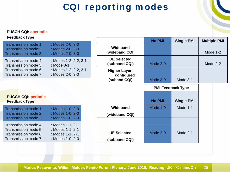
CQI reporting modes
No PMI Single PMI Multiple PMI
Wideband(wideband CQI) Mode 1-2
UE Selected(subband CQI) Mode 2-0 Mode 2-2
Higher Layer-configured
(suband CQI) Mode 3-0 Mode 3-1
Transmission mode 4 : Modes 1-2, 2-2, 3-1 Transmission mode 5 : Mode 3-1Transmission mode 6 : Modes 1-2, 2-2, 3-1Transmission mode 7 : Modes 2-0, 3-0
Transmission mode 1 : Modes 2-0, 3-0Transmission mode 2 : Modes 2-0, 3-0Transmission mode 3 : Modes 2-0, 3-0
PMI Feedback Type
No PMI Single PMI
Wideband Mode 1-0 Mode 1-1
(wideband CQI)
UE Selected Mode 2-0 Mode 2-1
(subband CQI)
Transmission mode 4 : Modes 1-1, 2-1Transmission mode 5 : Modes 1-1, 2-1Transmission mode 6 : Modes 1-1, 2-1Transmission mode 7 : Modes 1-0, 2-0
Transmission mode 1 : Modes 1-0, 2-0Transmission mode 2 : Modes 1-0, 2-0Transmission mode 3 : Modes 1-0, 2-0
PUSCH CQI: aperiodicFeedback Type
PUCCH CQI: periodic Feedback Type
26Marius Pesavento, Willem Mulder, Femto Forum Plenary, June 2010, Reading, UK © mimoOn
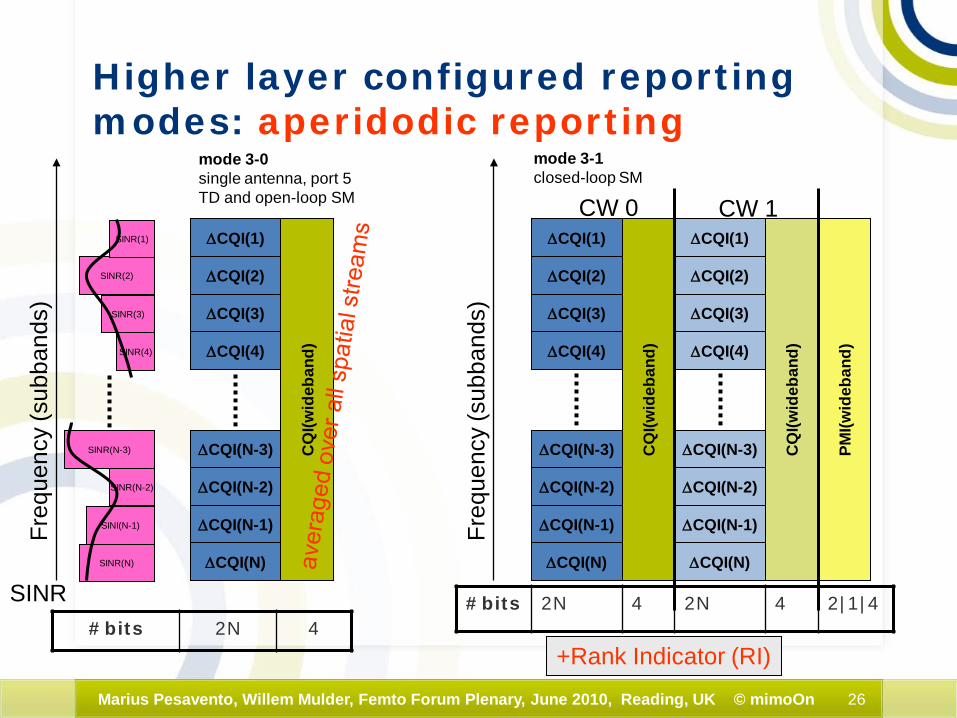
Higher layer configured reporting modes: aperidodic reporting
#bits 2N 4
∆CQI(2)
∆CQI(1)
∆CQI(3)
∆CQI(4)
∆CQI(N-3)
∆CQI(N-2)
∆CQI(N-1)
∆CQI(N)
CQ
I(wid
eban
d)
Freq
uenc
y (s
ubba
nds)
∆CQI(2)
∆CQI(1)
∆CQI(3)
∆CQI(4)
∆CQI(N-3)
∆CQI(N-2)
∆CQI(N-1)
∆CQI(N)
CQ
I(wid
eban
d)
Freq
uenc
y (s
ubba
nds)
mode 3-0single antenna, port 5 TD and open-loop SM
mode 3-1closed-loop SM
PMI(w
ideb
and)
∆CQI(2)
∆CQI(1)
∆CQI(3)
∆CQI(4)
∆CQI(N-3)
∆CQI(N-2)
∆CQI(N-1)
∆CQI(N)
CQ
I(wid
eban
d)
CW 0 CW 1
#bits 2N 4 2N 4 2|1|4
+Rank Indicator (RI)
SINR(2)
SINR(1)
SINR(3)
SINR(4)
SINR(N-2)
SINI(N-1)
SINR(N)
SINR
SINR(N-3)
27Marius Pesavento, Willem Mulder, Femto Forum Plenary, June 2010, Reading, UK © mimoOn
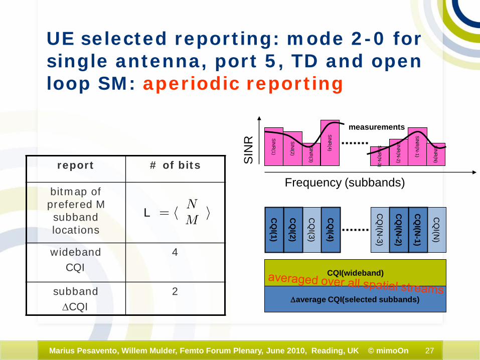
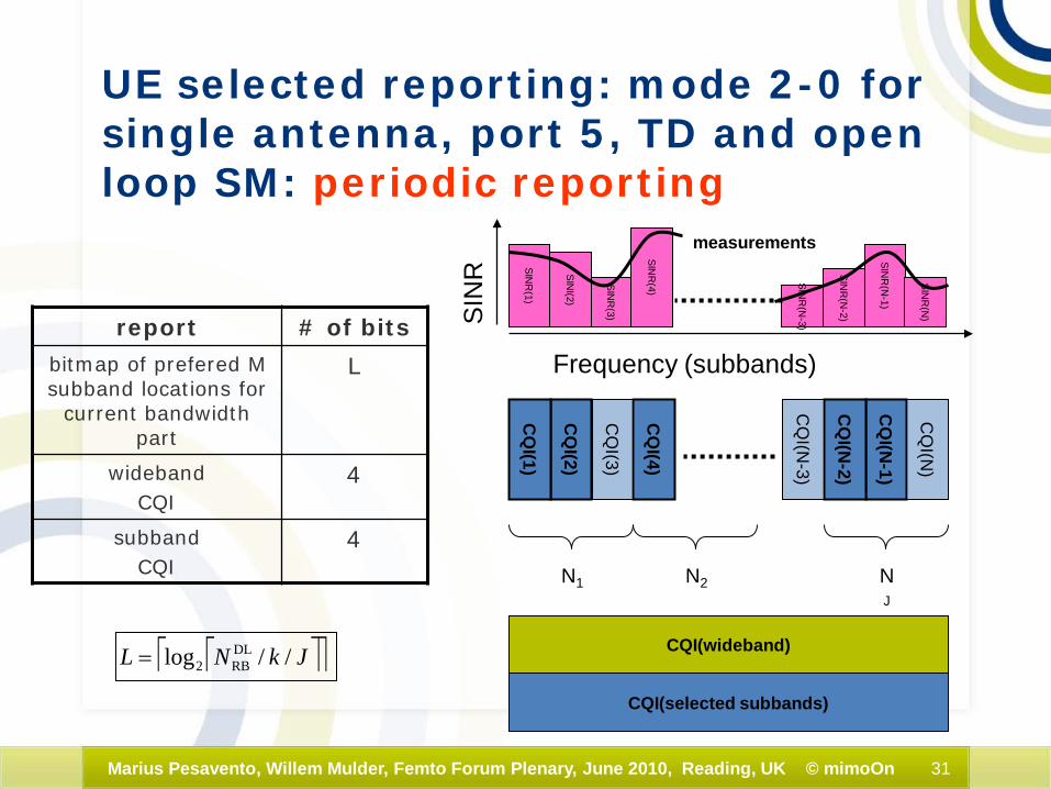
UE selected reporting: mode 2-0 for single antenna, port 5, TD and open loop SM: aperiodic reporting
report # of bits
bitmap of prefered M subband locations
widebandCQI
4
subband ∆CQI
2
L CQ
I(N-1)
CQ
I(N)
CQ
I(N-2)
CQ
I(N-3)
CQ
I(4)
CQ
I(3)
CQ
I(2)
CQ
I(1)
Frequency (subbands)
SINR
(N-1)
SINR
(N)
SINR
(N-2)
SINR
(N-3)
SINR
(4)
SINR
(3)
SINI(2)
SINR
(1)
measurements
CQI(wideband)
∆average CQI(selected subbands)
SIN
R
28Marius Pesavento, Willem Mulder, Femto Forum Plenary, June 2010, Reading, UK © mimoOn
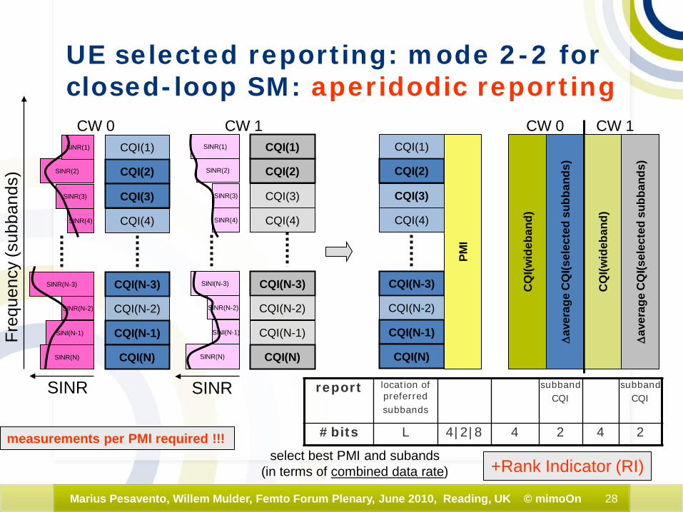
UE selected reporting: mode 2-2 for closed-loop SM: aperidodic reporting
report location ofpreferredsubbands
subbandCQI
subbandCQI
#bits L 4|2|8 4 2 4 2measurements per PMI required !!!select best PMI and subands
(in terms of combined data rate)
SINR SINR
CQI(2)
CQI(1)
CQI(3)
CQI(4)
CQI(N-3)
CQI(N-2)
CQI(N-1)
CQI(N)
Freq
uenc
y (s
ubba
nds)
SINR(2)
SINR(1)
SINR(3)
SINR(4)
SINR(N-3)
SINR(N-2)
SINI(N-1)
SINR(N)
SINR(2)
SINR(1)
SINR(3)
SINR(4)
SINR(N-2)
SINI(N-1)
SINR(N)
CW 0 CW 1
SINI(N-3)
CQI(2)
CQI(1)
CQI(3)
CQI(4)
CQI(N-3)
CQI(N-2)
CQI(N-1)
CQI(N)
∆av
erag
e C
QI(s
elec
ted
subb
ands
)
∆av
erag
e C
QI(s
elec
ted
subb
ands
)
CW 0 CW 1
CQI(2)
CQI(1)
CQI(3)
CQI(4)
CQI(N-3)
CQI(N-2)
CQI(N-1)
CQI(N)
PMI
CQ
I(wid
eban
d)
CQ
I(wid
eban
d)
+Rank Indicator (RI)

29Marius Pesavento, Willem Mulder, Femto Forum Plenary, June 2010, Reading, UK © mimoOn
Wideband CQI reporting modes: aperidodic reporting
#bits 4 4 2N| N|4N
PMI(2)
PMI(1)
PMI(3)
PMI(4)
PMI(N-3)
PMI(N-2)
PMI(N-1)
PMI(N)
CQ
I(wid
eban
d)
Freq
uenc
y (s
ubba
nds)
mode 1-2closed-loop SM
CQ
I(wid
eban
d)
CW0 CW1+Rank Indicator (RI)
SINR(2)
SINR(1)
SINR(3)
SINR(4)
SINR(N-2)
SINI(N-1)
SINR(N)
SINR
SINR(N-3)
30Marius Pesavento, Willem Mulder, Femto Forum Plenary, June 2010, Reading, UK © mimoOn
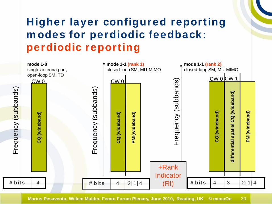
Higher layer configured reporting modes for perdiodic feedback: perdiodic reporting
#bits 4 2|1|4
CQ
I(wid
eban
d)
Freq
uenc
y (s
ubba
nds)
CQ
I(wid
eban
d)
Freq
uenc
y (s
ubba
nds)
mode 1-1 (rank 1)closed-loop SM, MU-MIMO
mode 1-1 (rank 2)closed-loop SM, MU-MIMO
PMI(w
ideb
and)
diffe
rent
ial s
patia
l CQ
I(wid
eban
d)
CW 0 CW 1
#bits 4 3 2|1|4
PMI(w
ideb
and)
CW 0
CQ
I(wid
eban
d)
Freq
uenc
y (s
ubba
nds)
mode 1-0 single antenna port,open-loop SM, TD
#bits 4
CW 0
+Rank Indicator
(RI)
31Marius Pesavento, Willem Mulder, Femto Forum Plenary, June 2010, Reading, UK © mimoOn
UE selected reporting: mode 2-0 for single antenna, port 5, TD and open loop SM: periodic reporting
report # of bits
bitmap of prefered M subband locations for
current bandwidthpart
L
widebandCQI
4
subband CQI
4
CQ
I(N-1)
CQ
I(N)
CQ
I(N-2)
CQ
I(N-3)
CQ
I(4)
CQ
I(3)
CQ
I(2)
CQ
I(1)
Frequency (subbands)
SINR
(N-1)
SINR
(N)
SINR
(N-2)
SINR
(N-3)
SINR
(4)
SINR
(3)
SINI(2)
SINR
(1)
measurements
CQI(wideband)
CQI(selected subbands)
SIN
R
N1 N2 NJ
JkNL //log DLRB2=

32Marius Pesavento, Willem Mulder, Femto Forum Plenary, June 2010, Reading, UK © mimoOn
UE selected reporting: mode 2-1for closed-loop SM: periodic reporting
report location of preferred
subbands in Bandwidth part j
sub-bandCQI
sub-bandCQI
#bits L 2|1|4 4 4 3 3
JkNL //log DLRB2=
CQI(2)
CQI(1)
CQI(3)
CQI(4)
CQI(N-3)
CQI(N-2)
CQI(N-1)
CQI(N)
Freq
uenc
y (s
ubba
nds)
SINR(2)
SINR(1)
SINR(3)
SINR(4)
SINR(N-3)
SINR(N-2)
SINI(N-1)
SINR(N)
SINR(2)
SINR(1)
SINR(3)
SINR(4)
SINR(N-2)
SINI(N-1)
SINR(N)
CW 0 CW 1
SINI(N-3)
CQI(2)
CQI(1)
CQI(3)
CQI(4)
CQI(N-3)
CQI(N-2)
CQI(N-1)
CQI(N)
CQ
I(sel
ecte
d su
bban
ds)
diffe
rent
ial C
QI(s
elec
ted
subb
ands
)
CW 0 CW 1measurements per PMI !!!
CQI(2)
CQI(1)
CQI(3)
CQI(4)
CQI(N-3)
CQI(N-2)
CQI(N-1)
CQI(N)
PMI
select best PMI and subands(in terms of combined data rate)
diffe
rent
ial s
patia
l CQ
I(wid
eban
d)
CQ
I(wid
eban
d)
SINR SINR
N1
NJ
k = subband sizeJ = number of bandwidth parts (see also next slide) +Rank Indicator (RI)
33Marius Pesavento, Willem Mulder, Femto Forum Plenary, June 2010, Reading, UK © mimoOn
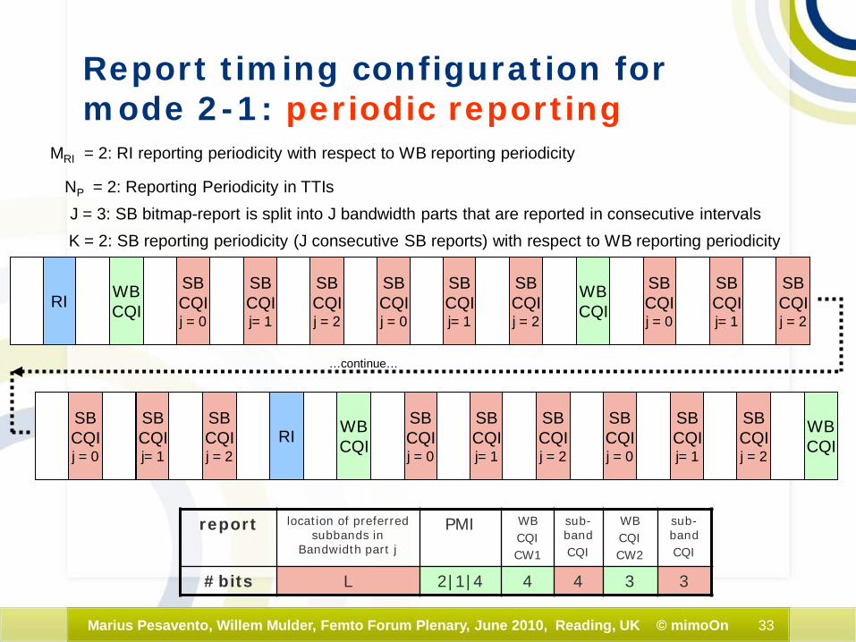
Report timing configuration for mode 2-1: periodic reporting
report location of preferred subbands in
Bandwidth part j
PMI WBCQICW1
sub-bandCQI
WBCQICW2
sub-bandCQI
#bits L 2|1|4 4 4 3 3
RISBCQIj = 0
WBCQI
SBCQIj= 1
SBCQIj = 2
WBCQI
J = 3: SB bitmap-report is split into J bandwidth parts that are reported in consecutive intervals
SBCQIj = 0
SBCQIj= 1
SBCQIj = 2
SBCQIj = 0
SBCQIj= 1
SBCQIj = 2
SBCQIj = 0
SBCQIj= 1
SBCQIj = 2
RISBCQIj = 0
WBCQI
SBCQIj= 1
SBCQIj = 2
WBCQI
SBCQIj = 0
SBCQIj= 1
SBCQIj = 2
K = 2: SB reporting periodicity (J consecutive SB reports) with respect to WB reporting periodicity
MRI = 2: RI reporting periodicity with respect to WB reporting periodicity
NP = 2: Reporting Periodicity in TTIs
…continue…
34Marius Pesavento, Willem Mulder, Femto Forum Plenary, June 2010, Reading, UK © mimoOn
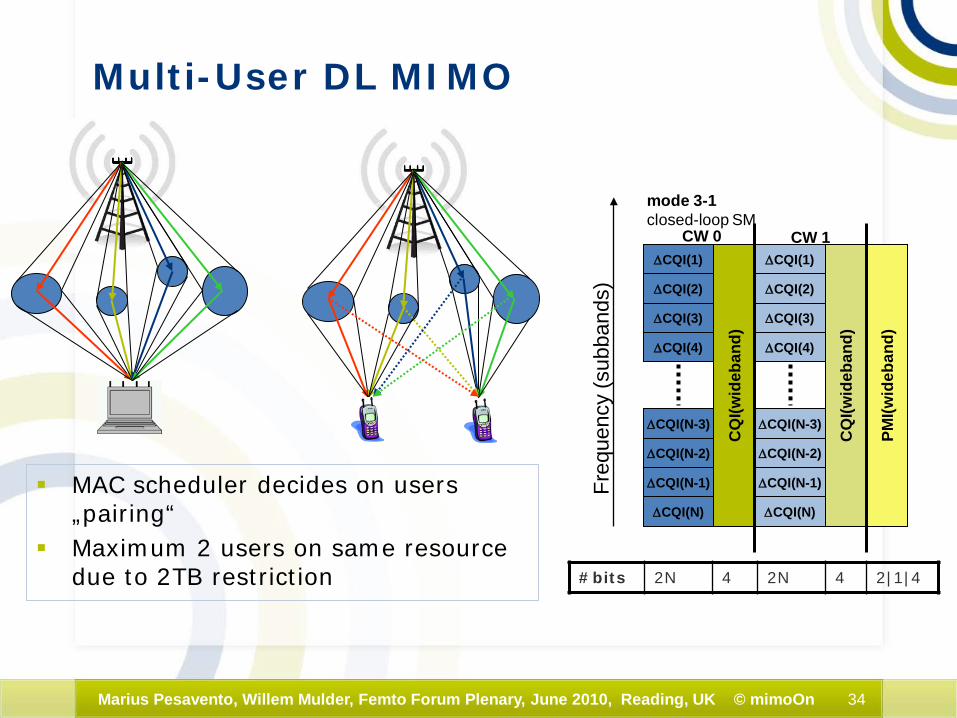
Multi-User DL MIMO
MAC scheduler decides on users „pairing“
Maximum 2 users on same resource due to 2TB restriction
∆CQI(2)
∆CQI(1)
∆CQI(3)
∆CQI(4)
∆CQI(N-3)
∆CQI(N-2)
∆CQI(N-1)
∆CQI(N)
CQ
I(wid
eban
d)
Freq
uenc
y (s
ubba
nds)
mode 3-1closed-loop SM
PMI(w
ideb
and)
∆CQI(2)
∆CQI(1)
∆CQI(3)
∆CQI(4)
∆CQI(N-3)
∆CQI(N-2)
∆CQI(N-1)
∆CQI(N)
CQ
I(wid
eban
d)
CW 0 CW 1
#bits 2N 4 2N 4 2|1|4
35Marius Pesavento, Willem Mulder, Femto Forum Plenary, June 2010, Reading, UK © mimoOn
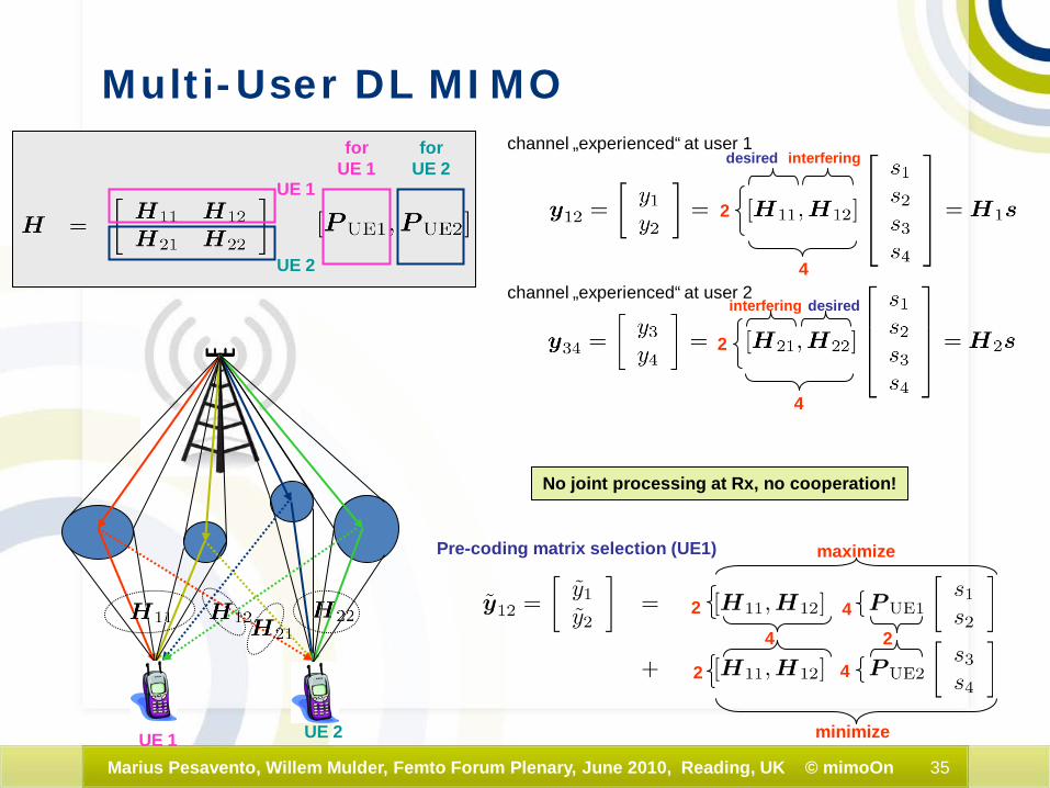
channel „experienced“ at user 1
channel „experienced“ at user 2
No joint processing at Rx, no cooperation!
4
2
4
2
desired interfering
desiredinterfering
Pre-coding matrix selection (UE1) maximize
minimize
2
2
44
4
2
UE 1
UE 2
forUE 1
forUE 2
UE 1 UE 2
Multi-User DL MIMO
36Marius Pesavento, Willem Mulder, Femto Forum Plenary, June 2010, Reading, UK © mimoOn
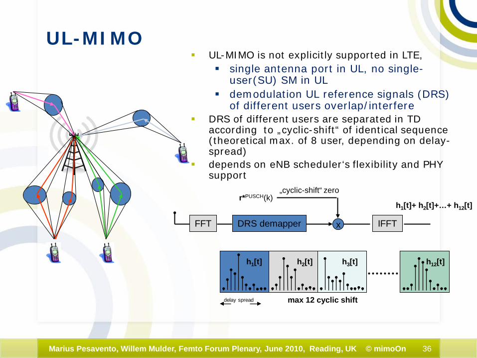
UL-MIMO UL-MIMO is not explicitly supported in LTE,
single antenna port in UL, no single-user(SU) SM in UL
demodulation UL reference signals (DRS) of different users overlap/interfere
DRS of different users are separated in TD according to „cyclic-shift“ of identical sequence (theoretical max. of 8 user, depending on delay-spread)
depends on eNB scheduler‘s flexibility and PHY support
delay spread max 12 cyclic shift
h1[t] h2[t] h3[t] h12[t]
r*PUSCH(k)
DRS demapperFFT x
h1[t]+ h2[t]+…+ h12[t]
„cyclic-shift“ zero
IFFT

37Marius Pesavento, Willem Mulder, Femto Forum Plenary, June 2010, Reading, UK © mimoOn
Source: 3GPP self evaluation results, 3GPP TSG-RAN chair, oct 2009
Spectral efficiency 3GPP self-evaluation results
38Marius Pesavento, Willem Mulder, Femto Forum Plenary, June 2010, Reading, UK © mimoOn
0
2000000
4000000
6000000
8000000
10000000
12000000
14000000
-10 -5 0 5 10 15 20SNR in dB
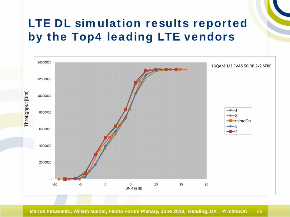
12mimoOn34
16QAM 1/2 EVA5 50 RB 2x2 SFBC
LTE DL simulation results reported by the Top4 leading LTE vendors
Thro
ughp
ut [B
its]
39Marius Pesavento, Willem Mulder, Femto Forum Plenary, June 2010, Reading, UK © mimoOn
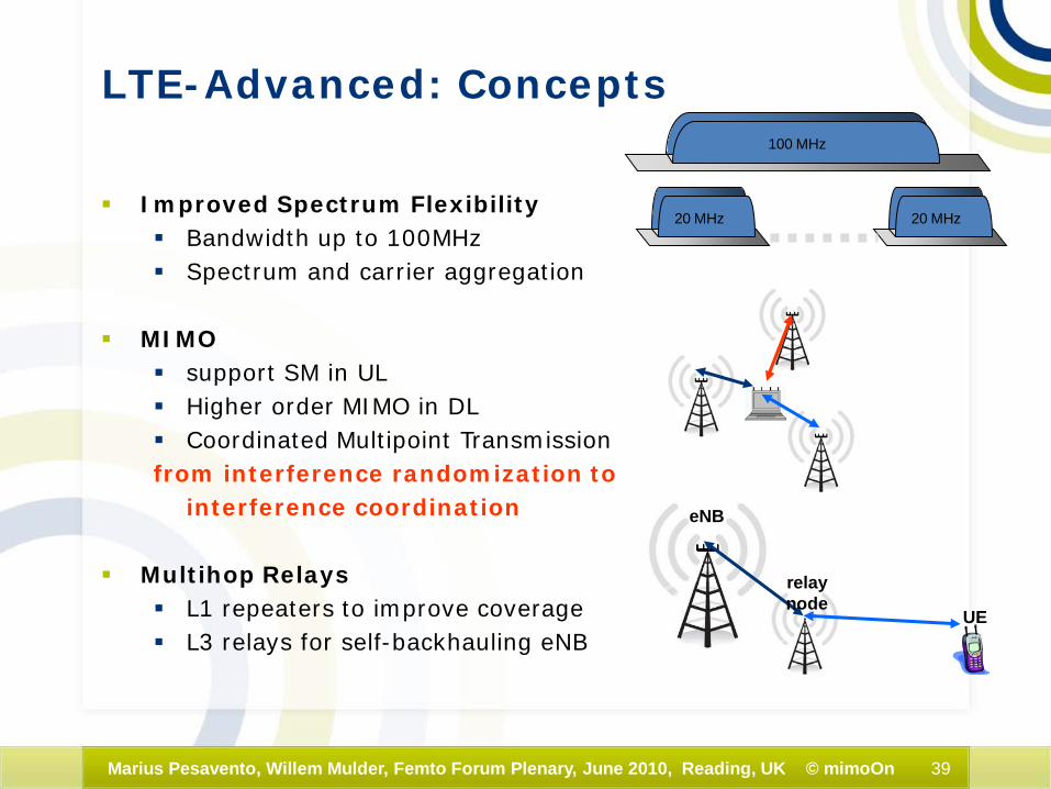
LTE-Advanced: Concepts
Improved Spectrum Flexibility Bandwidth up to 100MHz Spectrum and carrier aggregation
MIMO support SM in UL Higher order MIMO in DL Coordinated Multipoint Transmissionfrom interference randomization to
interference coordination
Multihop Relays L1 repeaters to improve coverage L3 relays for self-backhauling eNB
100 MHz
20 MHz 20 MHz
eNB
relaynode
UE

40Marius Pesavento, Willem Mulder, Femto Forum Plenary, June 2010, Reading, UK © mimoOn
LTE-Advancedadvanced MIMO receiver structure
SD-SIC for OFDMA2 codewords used,
each S/P-mapped onto 2 Tx antennas
1,kY2,kY
LMMSE / Soft IC
LLR calc. Rate matching
LLR calc.
Decoder
Decoder
Signal construction
Signal construction
Channel estimate
Channel estimate
3,kY4,kY
S/P
S/P Rate matching
Figure: NSN: R1-083732 / 2008-09-23
41Marius Pesavento, Willem Mulder, Femto Forum Plenary, June 2010, Reading, UK © mimoOn
End of Part 2
Thank you!!!