lt cage st - mt ortho · table of contents. lt-cage™ lumbar ... general anesthesia with...
TRANSCRIPT
LT-CAGE™
Lumbar Tapered Fusion DeviceSurgical Technique
as described by:
Thomas A. Zdeblick, M.D.University of WisconsinMadison, Wisconsin
J. Kenneth Burkus, M.D.Hughston ClinicColumbus, Georgia
INTRODUCTION 1
ADVANTAGES 2
PREOPERATIVE TEMPLATING 3
INTRAOPERATIVE PREPARATION 4
STEP 1
MIDLINE MARKING AND ALIGNMENT 5
MIDLINE MARKING AND
PREPARATION OF THE DISC SPACE 6
STEP 2
DISTRACTION AND OUTER SLEEVE PLACEMENT 8
STEP 3
VERTEBRAL ENDPLATE REAMING 11
STEP 4
IMPLANTATION 15
SINGLE BARREL TECHNIQUE 18
LUMBAR TAPERED INSTRUMENTS 19
IMPORTANT MEDICAL INFORMATION
TA B L E O F C O N T E N T S
LT-CAGE™ LUMBAR TAPERED FUSION DEVICE
Dear Colleagues:
One goal of anterior lumbar interbody surgery is the restoration of lumbarlordosis and sagittal balance. Today’s cylindrical constructs may achieve this goalby asymmetrical distraction and reaming of the vertebral endplates. While thistechnique can restore lumbar lordosis, it typically requires substantial reamingof the posterior aspect of the vertebral endplate.
The LT-CAGE™ Lumbar Tapered Fusion Device restores lordosis and sagittalbalance through a tapered implant design. Placement of the LT-CAGE™ Devicewith the Lumbar Tapered Instruments allows for symmetrical distraction of thevertebral bodies and significantly less reaming of the vertebral endplates thantraditional cylindrical interbody constructs. Furthermore, the Lumbar TaperedInstruments are designed to easily and reproducibly place the LT-CAGE™ Device.It is my feeling that the restoration of lordosis, combined with solid arthrodesis,leads to a better long-term result.
This technique details the placement of the LT-CAGE™ Lumbar Tapered FusionDevice through an open, anterior technique. In addition to the surgical steps,this technique highlights the key features of the Lumbar Tapered Instruments.Precise adherence to the details of insertion will allow you to gain the benefits ofthis powerful threaded device, with minimal difficulties. I believe that you too willfind this a significant step forward in the field of interbody surgery.
Sincerely,
Thomas A. Zdeblick, M.D.University of WisconsinMadison, Wisconsin
I N T R O D U C T I O N
1

2
A D VA N TA G E S
1. Implant provides anatomic restoration of lordosis with maximumvertebral endplate preservation.
2. Implant design reduces lateral requirement for discectomy.
3. Integrated system design allows for placement of the constructs andfacilitates a consistent, reproducible procedure.
4. Sequential distraction process for desired disc space and heightrestoration prior to endplate preparation.
5. Double barrel design facilitates bi-lateral placement ofLT-CAGE™ Devices.
6. Color-coded instruments and cases that facilitate size specificdevice placement.
7. Adjustable depth stops allow controlled passage of instrumentsthrough working channels.

3
Once the appropriate spinal level has been identified, the proper size construct must be selected.Templates are available to facilitate proper implant selection from plain radiographs, CT or MRIscans. These templates are available in appropriate reduction or magnification ratios forradiographs and CT or MRI scans (Figure 1). To determine the magnification of a CT or MRIscan, match the scale on the template with the scale on the CT or MRI scan. Example templatesare shown below.
P R E O P E R AT I V E T E M P L AT I N G
These templates allow the surgeon to measurenormal, adjacent disc space height anddetermine intraoperative distraction height. Inusing the templates, the physician must ensurethat the constructs remain within the lateralborders of the intervertebral disc space. Construct length, reaming depth andcountersink may also be assessed preoperativelyusing the templates.
Once the construct size is determined, note thediameter of the leading end. This diameter isused to reference the correspondinginstrumentation. A color-coding system is usedto differentiate each of the leading diameters.
14mm – Red16mm – Green18mm – Blue
100
100
0
10
20
30
40
50
LT - CAGE™ LUMBAR TR APEREDTT FUSION DEVICE TEMPLATES
10mm
12mm
14mm
ameter)
18 X 23 (21.5 trailing diameter) 18 X 26 (22 trailing diameter)
LT-Cage™ Lumbar Tapered Fusion Device TemplatesLT Distractors and Cages
FIGURE 1

4
I N T R A O P E R AT I V E P R E P A R AT I O N
Intraoperatively, the patient is placed on the operating table in a supine position. Compressionstockings should be placed on the patient. General anesthesia with endotracheal intubation isadministered.
The lumbar spine may be approached througheither a transperitoneal or an anteriorretroperitoneal exposure (Figure 2). The amountof great vessel release and retraction should belimited to that required for insertion of theinstruments and constructs. At the L4-L5 level,the iliolumbar and segmental vessels should beidentified and ligated if necessary in order toachieve adequate mobilization of the greatvessels. At L5-SI, the middle sacral artery istypically ligated and divided. Care should betaken at L5-SI to only use blunt dissection inorder to minimize injury to the presacralneural plexus.
FIGURE 2

5
M I D L I N E M A R K I N G A N D A L I G N M E N T
FIGURE 3
The center of the disc should be located and marked withthe assistance of both A/P and lateral fluoroscopy.Accurate identification of the midline is essential for thesuccessful implantation of two LT-CAGE™ Devices.
Attach the Centering Pin to the CenteringPin/Template Shaft and place at the center of thedisc (Figure 3). The position is checked with A/Pfluoroscopy and adjusted as needed. Since ablock discectomy is to be performed, marks areplaced at midline on the vertebral bodies bothcephalad and caudal to the Centering Pin(Figure 3A). A lateral fluoroscopic check ishelpful in confirming the targeted lumbarlevel (Figure 3B).
S T E P
1
FIGURE 3A
FIGURE 3B
6
MIDLINE MARKING AND PREPARATION OF THE DISC SPACE
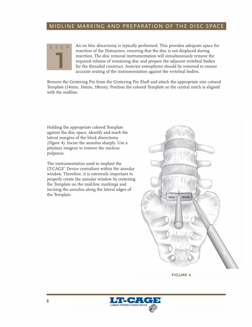
An en bloc discectomy is typically performed. This provides adequate space forinsertion of the Distractors, ensuring that the disc is not displaced duringinsertion. The disc removal instrumentation will simultaneously remove therequired volume of remaining disc and prepare the adjacent vertebral bodiesfor the threaded construct. Anterior osteophytes should be removed to ensureaccurate seating of the instrumentation against the vertebral bodies.
Remove the Centering Pin from the Centering Pin Shaft and attach the appropriate size coloredTemplate (14mm, 16mm, 18mm). Position the colored Template so the central notch is alignedwith the midline.
Holding the appropriate colored Templateagainst the disc space, identify and mark thelateral margins of the block discectomy(Figure 4). Incise the annulus sharply. Use apituitary rongeur to remove the nucleuspulposus.
The instrumentation used to implant theLT-CAGE™ Device centralizes within the annularwindow. Therefore, it is extremely important toproperly create the annular window by centeringthe Template on the mid-line markings andincising the annulus along the lateral edges ofthe Template.
S T E P
1
FIGURE 4

7
MIDLINE MARKING AND PREPARATION OF THE DISC SPACE
FIGURE 5
FIGURE 6
Curettes are used to remove thecartilaginous endplates. Thesesteps are performed under directvisualization, taking care not toperforate posteriorly or laterally.Lateral fluoroscopy may be used
to confirm the extent of the posterior discremoval through visualization of discectomyinstruments. Use care to avoid exceeding thelateral margins defined by the block discectomyTemplate annulus anterolaterally (Figure 5).
After completion of the block discectomy, theanterolateral annulus remains intact and acts toenhance construct stability (Figure 6).
The procedure continues utilizing specificinstrumentation for the appropriate diameter devices.
S T E P
1
8
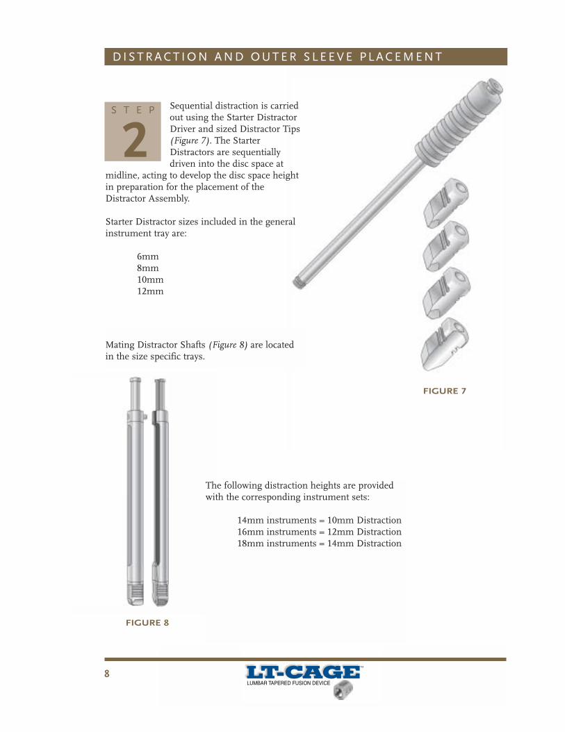
Sequential distraction is carriedout using the Starter DistractorDriver and sized Distractor Tips(Figure 7). The StarterDistractors are sequentiallydriven into the disc space at
midline, acting to develop the disc space heightin preparation for the placement of theDistractor Assembly.
Starter Distractor sizes included in the generalinstrument tray are:
6mm8mm10mm12mm
The following distraction heights are providedwith the corresponding instrument sets:
14mm instruments = 10mm Distraction16mm instruments = 12mm Distraction18mm instruments = 14mm Distraction
D I S T R A C T I O N A N D O U T E R S L E E V E P L A C E M E N T
FIGURE 7
S T E P
2
FIGURE 8
Mating Distractor Shafts (Figure 8) are locatedin the size specific trays.
9
D I S T R A C T I O N A N D O U T E R S L E E V E P L A C E M E N T
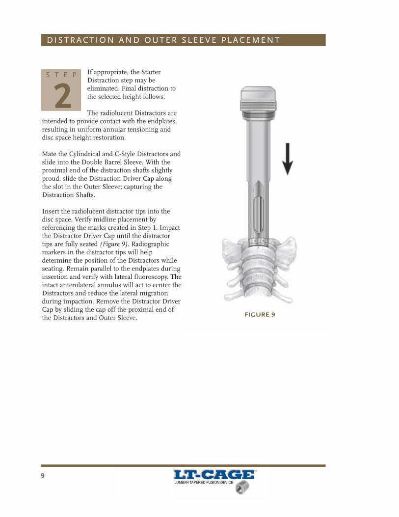
If appropriate, the StarterDistraction step may beeliminated. Final distraction tothe selected height follows.
The radiolucent Distractors areintended to provide contact with the endplates,resulting in uniform annular tensioning anddisc space height restoration.
Mate the Cylindrical and C-Style Distractors andslide into the Double Barrel Sleeve. With theproximal end of the distraction shafts slightlyproud, slide the Distraction Driver Cap alongthe slot in the Outer Sleeve; capturing theDistraction Shafts.
Insert the radiolucent distractor tips into thedisc space. Verify midline placement byreferencing the marks created in Step 1. Impactthe Distractor Driver Cap until the distractortips are fully seated (Figure 9). Radiographicmarkers in the distractor tips will helpdetermine the position of the Distractors whileseating. Remain parallel to the endplates duringinsertion and verify with lateral fluoroscopy. Theintact anterolateral annulus will act to center theDistractors and reduce the lateral migrationduring impaction. Remove the Distractor DriverCap by sliding the cap off the proximal end ofthe Distractors and Outer Sleeve.
S T E P
2
FIGURE 9

1 0
D I S T R A C T I O N A N D O U T E R S L E E V E P L A C E M E N T
Place the Driver Cap and impactthe Outer Sleeve until fullyseated (Figure 10).
Fluoroscopic control is helpfulin assessing distraction height
and orientation of the Distractors. TheDistractors act as a centering and alignmentguide for the procedure, it is essential that theyare located properly.
NOTE: Prior to fully seating the Outer Sleeve,all vascular structures should be accuratelyidentified and adequately retracted.Intraoperative fluoroscopy is useful inconfirming that the Outer Sleeve is fully seatedagainst the vertebral bodies and properlyoriented within the disc space. The Outer SleeveBarrel extensions are intended to assist inkeeping soft tissue and vascular structuresfrom slipping under the lateral margin of theOuter Sleeve.
S T E P
2
FIGURE 10

1 1
V E R T E B R A L E N D P L AT E R E A M I N G
With the Double Barrel Outer Sleeve fully seated, use the Instrument Remover tocarefully remove the Cylindrical Distractor to allow a cylindrical working channel(Figure 11). The C-Styled Distractor remains in place (Figure 11A and Figure 11B).
S T E P
3
FIGURE 11A
FIGURE 11B
FIGURE 11

1 2
V E R T E B R A L E N D P L AT E R E A M I N G
The appropriately sized Hollow Reamer is used to prepare the disc space forplacement of the LT-CAGE™ Devices.
Attach the Depth Stop to the Reamer. Hold the knurled sections of the Depth Stopand compress, allowing the Depth Stop to move freely over the depth grooves.Slide the Depth Stop and orient the square window to show the etched depth
markings on the shaft of the Reamer (Figure 12). Release the proximal knurled portion of theDepth Stop allowing it to lock in position. Verify that the desired depth compression appears inthe window.
NOTE: The Depth Stop may need to be rotated to view the depth setting in the window.
The appropriate Depth Stop setting should be chosen basedon the preoperative templating using axial CT or MR images.The depth selected should reflect the length of the threadedconstruct and the depth of the countersinking desired.
S T E P
3
FIGURE 12
1 3
V E R T E B R A L E N D P L AT E R E A M I N G
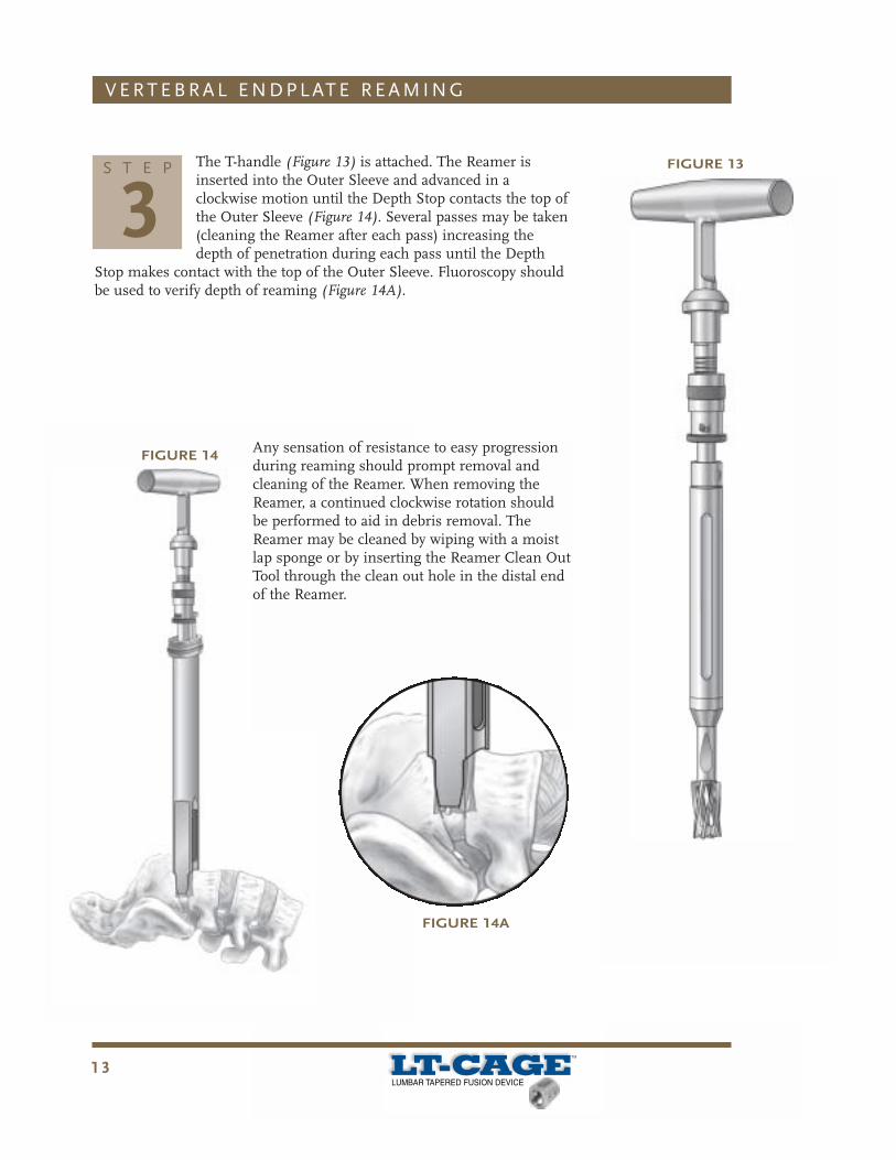
FIGURE 13The T-handle (Figure 13) is attached. The Reamer isinserted into the Outer Sleeve and advanced in aclockwise motion until the Depth Stop contacts the top ofthe Outer Sleeve (Figure 14). Several passes may be taken(cleaning the Reamer after each pass) increasing thedepth of penetration during each pass until the Depth
Stop makes contact with the top of the Outer Sleeve. Fluoroscopy shouldbe used to verify depth of reaming (Figure 14A).
S T E P
3
FIGURE 14
FIGURE 14A
Any sensation of resistance to easy progressionduring reaming should prompt removal andcleaning of the Reamer. When removing theReamer, a continued clockwise rotation shouldbe performed to aid in debris removal. TheReamer may be cleaned by wiping with a moistlap sponge or by inserting the Reamer Clean OutTool through the clean out hole in the distal endof the Reamer.
1 4
V E R T E B R A L E N D P L AT E R E A M I N G
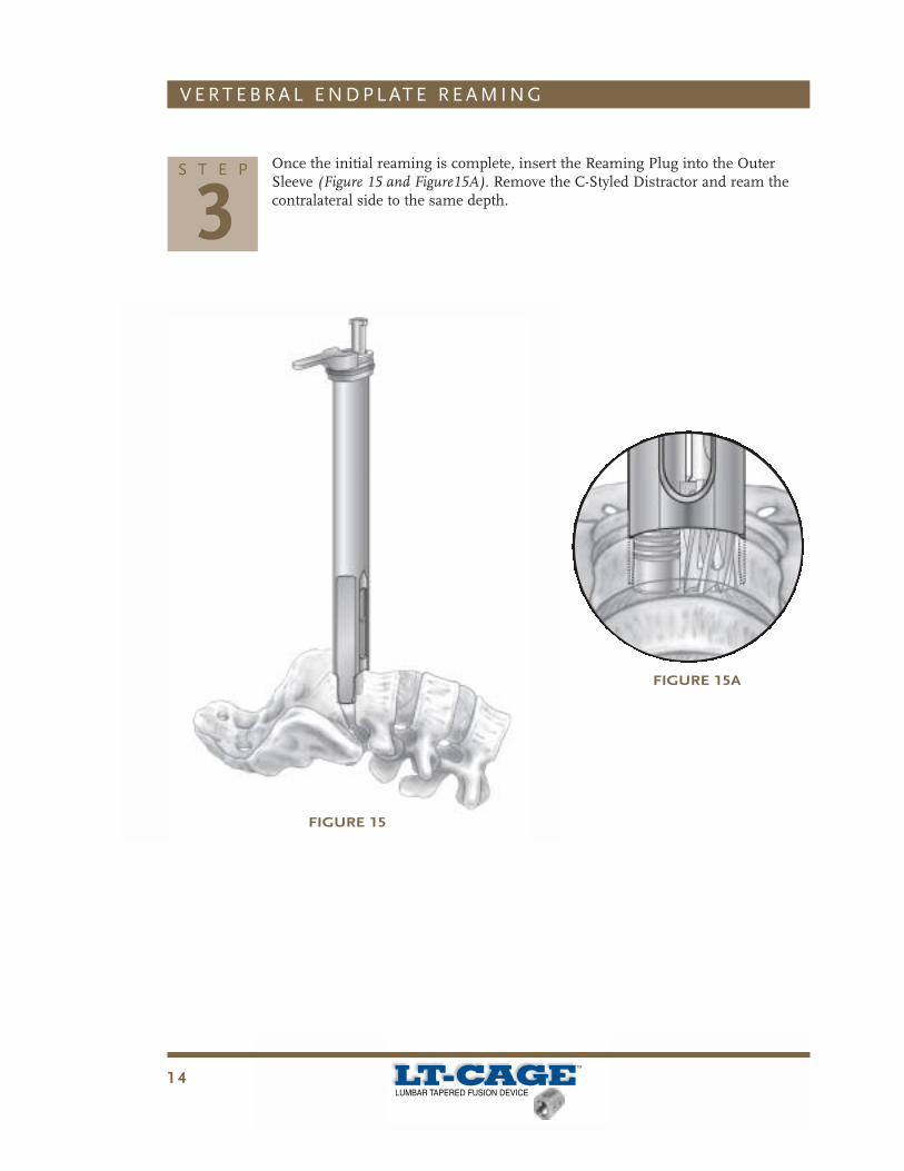
Once the initial reaming is complete, insert the Reaming Plug into the OuterSleeve (Figure 15 and Figure15A). Remove the C-Styled Distractor and ream thecontralateral side to the same depth.
S T E P
3
FIGURE 15
FIGURE 15A
1 5
I M P L A N TAT I O N
FIGURE 16A
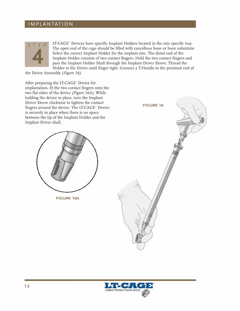
LT-CAGE™ Devices have specific Implant Holders located in the size specific tray.The open end of the cage should be filled with cancellous bone or bone substitute.Select the correct Implant Holder for the implant size. The distal end of theImplant Holder consists of two contact fingers. Hold the two contact fingers andpass the Implant Holder Shaft through the Implant Driver Sleeve. Thread theHolder to the Driver until finger tight. Connect a T-Handle to the proximal end of
the Driver Assembly (Figure 16).
S T E P
4
FIGURE 16
After preparing the LT-CAGE™ Device forimplantation, fit the two contact fingers onto thetwo flat sides of the device (Figure 16A). Whileholding the device in place, turn the ImplantDriver Sleeve clockwise to tighten the contactfingers around the device. The LT-CAGE™ Deviceis securely in place when there is no spacebetween the tip of the Implant Holder and theImplant Driver shaft.

1 6
The LT-CAGE™ Device is passed through the Outer Sleeve andinserted into the cylindrical, reamed feature (Figure 17). Theproximal end of the device is flush with the anterior apex of thevertebral body when the first concentric ring on the ImplantDriver is aligned with the top of the Outer Sleeve.
I M P L A N TAT I O N
S T E P
4FIGURE 17
FIGURE 17A
FIGURE 17B
Each subsequent ring indicates 3mm of devicecountersink. Advance until the proper countersinklevel is reached (Figure 17A). Device insertion mustbe completed with the T-Handle parallel to thedisc space.
A/P and lateral fluoroscopic checks are recommended toconfirm device positioning (Figure 17B).
The Implant Driver is disengaged from the LT-CAGE™
Device by unscrewing the Outer Sleeve of the ImplantDriver in a counterclockwise fashion. If necessary, theImplant Driver Wrench may be used at the collar of theOuter Sleeve to provide additional leverage in looseningthe Implant Driver.
The second LT-CAGE™ Device is placed at the samedepth as the first LT-CAGE™ Device. To assure theplacement is correct, confirm with a lateral C-arm view.

1 7
I M P L A N TAT I O N
In the final position, the LT-CAGE™ Lumbar Tapered Fusion Device should beslightly countersunk (2 – 5mm) from the anterior surface and within the lateralmargins of the vertebral bodies.
If necessary, an Implant Adjuster can be inserted into the proximal end of thedevice for alignment corrections. The T-handle should be placed parallel with the
disc space when the final implant depth is achieved.
S T E P
4In order to countersink the device, adequatereaming depth must have been achieved. Forexample, if a 23mm length device is beinginserted, the reaming depth must be greaterthan 23mm to allow the device to becountersunk. Trying to countersink in thesetting of inadequate reaming may result instripping and the potential loss/damage to thedevice/host interface.
A lateral fluoroscopic image may be taken toensure proper final placement. Where possible,pack additional bone graft around the proximalend and between the devices.

1 8
S I N G L E B A R R E L T E C H N I Q U E
1. Use the Centering Pin to identify and mark midline.2. Use the appropriate sized Template to determine the width of the
block discectomy. Complete the block discetomy as described in thistechnique Step 1.
3. Insert the Single Barrel Distractor in Side A. Use the Single BarrelDistractor Driver Cap to seat the distractor tip in place.
4. Guide the Single Barrel Outer Sleeve over the Distractor.5. Placing the Impactor Cap over the Outer Sleeve, seat the Outer
Sleeve so that it engages the disc space. Use the Single Barrel DriverCap to fully seat the Outer Sleeve. Remove the Single BarrelDistractor.
6. Fit the Reamer with the Depth Stop and ream to the desired depth.7. Remove the Reamer, insert the Reaming Plug within the Outer
Sleeve and seat in the disc space. Remove the Reaming Plug Shaftand the Outer Sleeve.
8. Repeat #3 through #7 to Side B.9. Utilizing the assembled Inserter, attach the LT-CAGE™ Device and
insert into Side B.10. After implanting the first LT-CAGE™ Device into Side B, remove the
Reaming Plug from Side A and seat the Outer Sleeve to aid in vesselprotection.
11. Insert the second LT-CAGE™ Device into Side A using the techniquedescribed in #9.
1 9
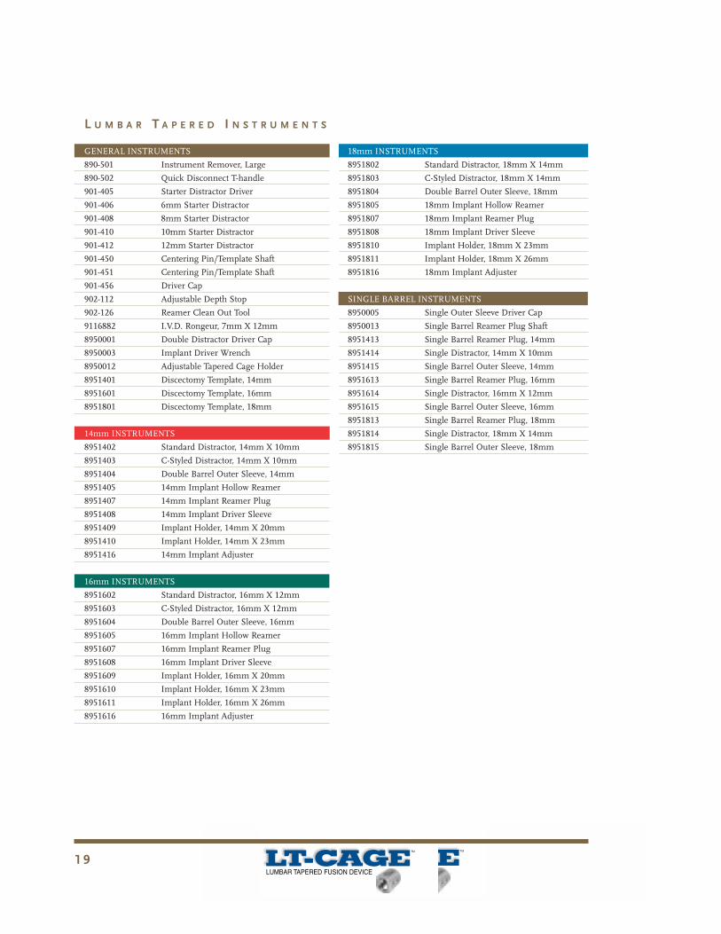
GENERAL INSTRUMENTS
890-501 Instrument Remover, Large
890-502 Quick Disconnect T-handle
901-405 Starter Distractor Driver
901-406 6mm Starter Distractor
901-408 8mm Starter Distractor
901-410 10mm Starter Distractor
901-412 12mm Starter Distractor
901-450 Centering Pin/Template Shaft
901-451 Centering Pin/Template Shaft
901-456 Driver Cap
902-112 Adjustable Depth Stop
902-126 Reamer Clean Out Tool
9116882 I.V.D. Rongeur, 7mm X 12mm
8950001 Double Distractor Driver Cap
8950003 Implant Driver Wrench
8950012 Adjustable Tapered Cage Holder
8951401 Discectomy Template, 14mm
8951601 Discectomy Template, 16mm
8951801 Discectomy Template, 18mm
14mm INSTRUMENTS
8951402 Standard Distractor, 14mm X 10mm
8951403 C-Styled Distractor, 14mm X 10mm
8951404 Double Barrel Outer Sleeve, 14mm
8951405 14mm Implant Hollow Reamer
8951407 14mm Implant Reamer Plug
8951408 14mm Implant Driver Sleeve
8951409 Implant Holder, 14mm X 20mm
8951410 Implant Holder, 14mm X 23mm
8951416 14mm Implant Adjuster
16mm INSTRUMENTS
8951602 Standard Distractor, 16mm X 12mm
8951603 C-Styled Distractor, 16mm X 12mm
8951604 Double Barrel Outer Sleeve, 16mm
8951605 16mm Implant Hollow Reamer
8951607 16mm Implant Reamer Plug
8951608 16mm Implant Driver Sleeve
8951609 Implant Holder, 16mm X 20mm
8951610 Implant Holder, 16mm X 23mm
8951611 Implant Holder, 16mm X 26mm
8951616 16mm Implant Adjuster
18mm INSTRUMENTS
8951802 Standard Distractor, 18mm X 14mm
8951803 C-Styled Distractor, 18mm X 14mm
8951804 Double Barrel Outer Sleeve, 18mm
8951805 18mm Implant Hollow Reamer
8951807 18mm Implant Reamer Plug
8951808 18mm Implant Driver Sleeve
8951810 Implant Holder, 18mm X 23mm
8951811 Implant Holder, 18mm X 26mm
8951816 18mm Implant Adjuster
SINGLE BARREL INSTRUMENTS
8950005 Single Outer Sleeve Driver Cap
8950013 Single Barrel Reamer Plug Shaft
8951413 Single Barrel Reamer Plug, 14mm
8951414 Single Distractor, 14mm X 10mm
8951415 Single Barrel Outer Sleeve, 14mm
8951613 Single Barrel Reamer Plug, 16mm
8951614 Single Distractor, 16mm X 12mm
8951615 Single Barrel Outer Sleeve, 16mm
8951813 Single Barrel Reamer Plug, 18mm
8951814 Single Distractor, 18mm X 14mm
8951815 Single Barrel Outer Sleeve, 18mm
L U M B A R T A P E R E D I N S T R U M E N T S

It is imperative that the indications, contraindications, warnings and precautions provided in this document be conveyed to the patient.
The following contains important medical information on the LT-CAGE™ Lumbar Tapered Fusion Device.
DESCRIPTION:The LT-CAGE™ Lumbar Tapered Fusion Device consists of a hollow, perforated, machined cylinder with opposing flats. The cage has a tapered design with an angle of 8.8o and is available in diametersranging from 14mm to 18mm at the narrow end of the taper, 17 to 22 mm at the wide end of the taper, and in lengths ranging from 20mm to 26mm. There are two holes on each of the two flat sides. Oneach of the two rounded aspects, there is a single rounded slot. The implants have a helical screw thread on the outer surface. One end of the device is closed and is used to engage the drive instrumentfor insertion of the device. The other end is open to be filled with bone graft.
The LT-CAGE™ implants are made from implant grade titanium alloy (Ti-6Al-4V) described by such standards as ASTM F136 or its ISO equivalent. No other warranties, express or implied, are made.Implied warranties of merchantability and fitness for a particular purpose or use are specifically excluded.
INDICATIONS:The LT-CAGE™ Lumbar Tapered Fusion Device is indicated for spinal fusion procedures in skeletally mature patients with degenerative disc disease (DDD) at one level from L2-S1. DDD is defined asdiscogenic back pain with degeneration of the disc confirmed by patient history and radiographic studies. These DDD patients may also have up to Grade I spondylolisthesis or retrolisthesis at the involvedlevel. LT-CAGE™ devices are to be used with autogenous bone graft and implanted via a laparoscopic or an open anterior approach.Patients receiving the LT-CAGE™ Lumbar Tapered Fusion Device should have had at least six months of nonoperative treatment prior to treatment with the LT-CAGE™ device.
SPECIAL PATIENT POPULATIONS:The safety and effectiveness of the LT-CAGE™ Lumbar Tapered Fusion Device have not been established in patients with any of the following conditions:
• spondylolisthesis or retrolisthesis of Grade II or greater;• more than one level to be fused;• revision of previous interbody fusion procedure(s);• postoperative steroidal or nonsteroidal anti-inflammatory medication requirements;• gross obesity;• ages less than 18 years or greater than 65 years;• osteoporosis, osteopenia, and/or osteomalacia;• pregnancy.
CONTRAINDICATIONS:The LT-CAGE™ Lumbar Tapered Fusion Device should not be implanted in patients with an active infection at the operative site or with an allergy to titanium or titanium alloy.
WARNINGS:
WARNING: The laparoscopic surgical approach is associated with a higher incidence of retrograde ejaculation, malpositioned implants, anatomic difficulties, and conversion to open surgical approach.Specifically: • In the LT-CAGE™ device clinical trial, men laparoscopically treated with the LT-CAGE™ device experienced a 16.2% incidence rate of retrograde ejaculation as compared to a 0% rate with
the femoral allograft control and 7.2% rate for men treated with the INTER FIX™ device. Of the 23 cases that were reported in the LT-CAGE™ device clinical trial, this condition resolved inapproximately 1/3 of the patients observed by 24 months.
• The laparoscopic surgical approach at the craniad lumbar levels (e.g., L2-3, L3-4, and L4-5) is associated with a high incidence of anatomic difficulties related to mobilizing the vessels aswell as an increased incidence of vascular injuries that may require conversion to open surgeries.
WARNING: A malpositioned implant is associated with significantly lower clinical and radiographic success rates.
PRECAUTIONS:
CAUTION: The LT-CAGE™ Lumbar Tapered Fusion Device should only be used by surgeons who are experienced in spinal fusion procedures and have undergone adequate training with this device, forboth laparoscopic and anterior, open procedures. A lack of adequate experience and/or training may lead to a higher incidence of surgical difficulties and malpositioned implants.
CAUTION: It is recommended that two LT-CAGE™ Lumbar Tapered Fusion Devices be implanted side by side at the surgical level. Clinical trial results indicate statistically better outcomes with theimplantation of two devices.
CAUTION: The implants and instruments must be sterilized prior to use according to the sterilization instructions provided in this package insert, unless supplied sterile and clearly labeled as such.
ADVERSE EVENTS:The adverse events, as shown in Table I, were reported from the 266 LT-CAGE™ device patients and 62 control patients enrolled in multi-center clinical studies. As additional information, adverse eventsreported in a clinical trial involving 185 patients who were enrolled in the INTER FIX™ Threaded Fusion Device treatment group are also presented. The rates presented are the number of occurrences forthe adverse event divided by the total number of patients with available data at a given time period. The adverse events occurring in both the laparoscopic surgical approach and the open surgical approachLT-CAGE™ device treatment groups are combined in order to present an overall rate.
Important Medical Information
1 Since fusion is a primary effectiveness endpoint, nonunions reported as adverse events by the investigator are not included in the table if the nonunion resulted in asecond surgery. These nonunion events are captured in the secondary surgery table and the fusion table.2 Statistical comparisons were based on data received through the 24 month evaluation.3 Includes adverse events that occurred after 30 months postoperative.4 Percent of 142 male patients.5 Percent of 83 male patients.
Table 1 – Adverse Events1
Operative(Number %)
Post-operative
(1 day -<2 Months)[Number (%)]
3 Month(≥2-<5 Months)
[Number (%)]
6 Month(≥5-<9 Months)
[Number (%)]
12 Month(≥9-<19 Months)
[Number (%)]
24 Month(≥19-<30 Months)
[Number (%)]
48 Months(≥30-<60 Months)
[Number (%)]
ADVERSE EVENTS �2
Complication� LT-Cage�N=266�
Control�N=62�
LT-Cage�N=266�
Control�N=62�
LT-Cage�N=266�
Control�N=62�
LT-Cage�N=266�
Control�N=62�
LT-Cage�N=266�
Control�N=62�
LT-Cage�N=227�
Control�N=62�
LT-Cage�N=5�
Control�N=30�
LT-Cage�# (% of 266)�3�
Control�# (% of 62)�3�
INTER �FIX�# (% of 185)�3�
Retrograde�Ejaculation�
10 (3.8)� 9 �(3.4)� 1 (0.4)� 3 �(1.1)� � � �23 �(8.6)� (16.2)� �4� 0 (0.0)�*
6 (3.2)� (7.2)� �5�
Neurological� 12 (4.5)� 2 �(3.2)� 7 (2.6)� 2�(3.2)�
1 �(1.6)� 4 �(1.5)� 3 �(4.8)� 5 (2.2)� 4 �(6.5)� 1 �(20.0)� �4 �(13.3)� � � �29 �(10.9)� 16 �(25.8)�*�27(14.6)�
Other� 19 (7.1)� 2 �(3.2)� 2 (0.8)� 2 (0.8)� 1 �(0.4)� 2 (0.9)� �3 �(10.0)� � � �26 �(9.8)� 5 (8.1)� 17 (9.2)�Gastrointestinal� 15 (5.6)� 3 �(4.8)� 4 (1.5)� 1 (0.4)� 1 �(1.6)� 1 �(0.4)� 1 �(1.6)� � � �21 �(7.9)� 5 (8.1)� 7 (3.8)�Malpositioned�Implant�
14 �(5.3)� 3 (1.1)� � � �17 �(6.4)� 0 (0.0)�* 0 (0.0)�*
Vascular�Intra-Op�
20 �(7.5)� 2 �(3.2)� � � �20 �(7.5)� 2 (3.2)� 16 (8.6)�
Incisional� 11 (4.1)� 6 �(9.7)� 2 (0.8)� 1 �(1.6)� 2 �(0.8)� 1 �(3.3)� � � �15 �(5.6)� 8 (12.9)� �11 �(5.9)�Back Pain� 1 (0.4)� 1 (0.4)� 3 �(4.8)� 7 (2.6)� 5 �(1.9)� 3 �(4.8)� 1 (0.4)� 6 �(9.7)� 1 �(3.3)� � � �15 �(5.6)� 13 (20.9)�* 16 (8.6)�Anatomical�Difficulty�
17 �(6.4)� � � �17 �(6.4)� 0 (0.0)�* 0 (0.0)�*
Urological� 2 �(0.8)� 10 (3.8)� 2 �(3.2)� 2 (0.8)� 1 (0.4)� 1 �(0.4)� � � �16 �(6.0)� 2 (3.2)� 10 (5.4)�Trauma� 2 (0.8)� 6 (2.3)� 3 (1.1)� 5 �(1.9)� 1 (0.4)� � � �17 �(6.4)� 0 (0.0)�*� � � � �20 �(10.8)�Spinal Event� 2 (0.8)� 1 �(1.6)� 2 (0.8)� 2 (0.8)� 1 �(1.6)� 6 �(2.3)� 3 (1.3)� 1 �(1.6)� 1(3.3)� � � �15 �(5.6)� 4 (6.5)� 23 �(12.4)�Leg �Pain� 3 (1.1)� 2 (0.9)� 5 (1.9)� 0 (0.0)� 4 (2.2)�Vascular�Post-Op�
5 (1.9)� 2 �(3.2)� 1 (0.4)� 1 �(0.4)� 7 (2.6)� 2 (3.2)� 2 (1.1)�
Depression� 1 (0.4)� 2 (0.8)� 3 �(1.1)� 6 (2.3)� 0 (0.0)� 0 (0.0)�*Sacroiliac �Pain� 2 (0.8)� 2 (0.8)� 1 �(1.6)� 1 �(0.4)� 1 �(1.6)� 2 (0.9)� 1 �(1.6)� 7 (2.6)� 3 (4.8)� 23 (12.4)�*Respiratory� 1 �(0.4)� 4 (1.5)� 1 �(1.6)� 1 �(0.4)� 6 (2.3)� 1 (1.6)� 7 (3.8)�Instrument�Difficulty�
4 �(1.5)� 4 (1.5)� 0 (0.0)� � �0 �(0.0)�
Visceral� 2 (0.8)� 2 (0.8)� 0 (0.0)� 0 (0.0)�Additional�Donor Site�
2 �(0.8)� 2 (0.8)� 0 (0.0)� 0 (0.0)�
Appendicitis� 1 (0.4)� 1 �(0.4)� 2 (0.8)� 0 (0.0)� 0 (0.0)�Vertebral �Bone�Fracture�
1 �(0.4)� 1 (0.4)� 2 (0.8)� 0 (0.0)� 2 (1.1)�
Subsidence� 1 (0.4)� 1 (0.4)� 0 (0.0)� 2 (1.1)�Dural �Tear� 1 (0.4)� 1 (0.4)� 0 (0.0)� 0 (0.0)�Other Pain� 1 �(1.6)� 2 (0.8)� 2 �(3.2)� 2 �(3.2)� 1(3.3)� 2 (0.8)� 6 (9.7)�* � � �18 �(9.7)�*Death� 1 (0.4)� 1 �(1.6)� 1 (0.4)� 1 (1.6)� 0 (0.0)�Peritoneal� 3 (1.1)� 3 (1.1)� 0 (0.0)� 3 (1.6)�Implant�Displacement/�Loosening�
1�(1.6)�
5 �(8.1)� 0 (0.0)� 6 (9.7)�* � �2 �(1.1)�
Graft Site Pain� 1 �(1.6)� 0 (0.0)� 1 (1.6)� � �1 �(0.5)�Non-Union� 1 �(0.4)� 1 (0.4)� 0 (0.0)� � �1 �(0.5)�Non-Union�(OUTCOME�PENDING)�
1 �(1.6)� 2 (0.8)� 1 (0.4)� 2 �(3.2)� 3 (1.1)� 3 (4.8)� � �2 �(1.1)�
Meningitis� 1�(1.6)�
0 (0.0)� 1 (1.6)� � �0 �(0.0)�
Implant�Breakage�
5�(8.1)�
0 (0.0)� 5 (8.1)�* � �0 �(0.0)�
* p = < 0.05
The most common and serious adverse events were intraoperative vascular injuries, neurological injuries, and retrograde ejaculation. A total of 20 vascular intraoperative events occurred in 20 patients inthe LT-CAGE™ device group. These events included: 1 injury to the vena cava, 17 injuries to the iliac vein, 1 lacerated hypogastric vein, and 1 bleeding from the bone bed. These were not significantlydifferent than those injuries seen in the control group or the INTER FIX™ group. In the control group, a total of 2 vascular intraoperative injuries occurred in 2 patients. These included: 1 injury to an iliacvein and 1 bleeding from the bone bed. The INTER FIX™ group had a total of 16 vascular intraoperative injuries.
A total of 29 neurological events occurred in 25 patients in the LT-CAGE™ device group. These events included: 13 radiculopathy; 2 radiculitis; 2 lumbar facet syndrome; 1 footdrop; 3 upper extremity nervetrauma; 3 reflex sympathetic dystrophies; 3 numbness; 2 nerve trauma. A total of 16 neurological events occurred in 13 patients in the control group. These events included: 1 radiculopathy with tinglingextremities; 2 patients with chronic back pain; 1 debilitating distribution symptoms; 3 cases of back and leg pain with other symptoms; 1 denervated abductor magnus muscle; 1 neuralgia paresthetica, 1nerve root scarring, 1 restless leg syndrome and 5 cases with numbness or warmth in legs. In the INTER FIX™ group, 27 neurological events occurred which were not significantly different than thoseinjuries seen in the LT-CAGE™ device group. In addition, the adverse events table presents leg and back pain adverse events and/or spinal events, such as disc space collapse, that, in some instances,had a neurological component.
Retrograde ejaculation occurred in 23 cases of males receiving the LT-CAGE™ device with 19 occurring during the first three months postoperative. No retrograde ejaculation was reported in the controlgroup patients which were implanted with femoral rings using an open surgical procedure. In the INTER FIX™ group, 6 cases of retrograde ejaculation occurred in males.
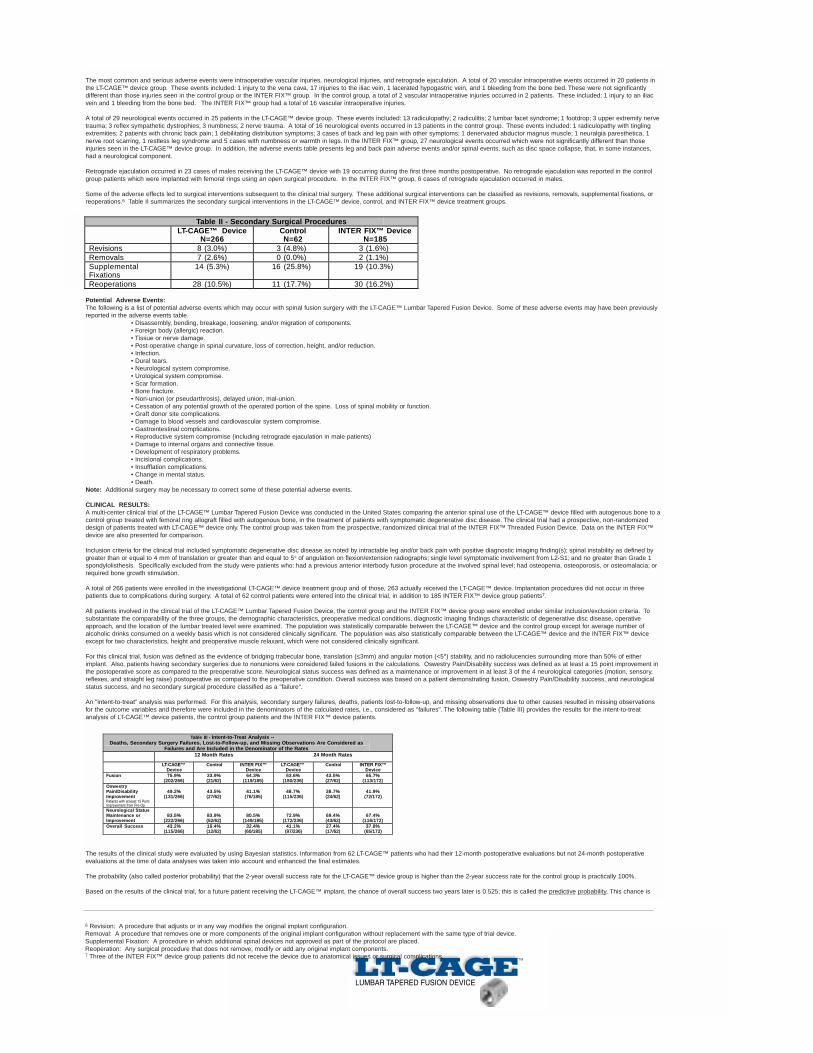
Some of the adverse effects led to surgical interventions subsequent to the clinical trial surgery. These additional surgical interventions can be classified as revisions, removals, supplemental fixations, orreoperations.6 Table II summarizes the secondary surgical interventions in the LT-CAGE™ device, control, and INTER FIX™ device treatment groups.
Potential Adverse Events:The following is a list of potential adverse events which may occur with spinal fusion surgery with the LT-CAGE™ Lumbar Tapered Fusion Device. Some of these adverse events may have been previouslyreported in the adverse events table.
• Disassembly, bending, breakage, loosening, and/or migration of components.• Foreign body (allergic) reaction.• Tissue or nerve damage.• Post-operative change in spinal curvature, loss of correction, height, and/or reduction.• Infection.• Dural tears.• Neurological system compromise.• Urological system compromise.• Scar formation.• Bone fracture.• Non-union (or pseudarthrosis), delayed union, mal-union.• Cessation of any potential growth of the operated portion of the spine. Loss of spinal mobility or function.• Graft donor site complications.• Damage to blood vessels and cardiovascular system compromise.• Gastrointestinal complications.• Reproductive system compromise (including retrograde ejaculation in male patients)• Damage to internal organs and connective tissue.• Development of respiratory problems.• Incisional complications.• Insufflation complications.• Change in mental status.• Death.
Note: Additional surgery may be necessary to correct some of these potential adverse events.
CLINICAL RESULTS:A multi-center clinical trial of the LT-CAGE™ Lumbar Tapered Fusion Device was conducted in the United States comparing the anterior spinal use of the LT-CAGE™ device filled with autogenous bone to acontrol group treated with femoral ring allograft filled with autogenous bone, in the treatment of patients with symptomatic degenerative disc disease. The clinical trial had a prospective, non-randomizeddesign of patients treated with LT-CAGE™ device only. The control group was taken from the prospective, randomized clinical trial of the INTER FIX™ Threaded Fusion Device. Data on the INTER FIX™device are also presented for comparison.
Inclusion criteria for the clinical trial included symptomatic degenerative disc disease as noted by intractable leg and/or back pain with positive diagnostic imaging finding(s); spinal instability as defined bygreater than or equal to 4 mm of translation or greater than and equal to 5o of angulation on flexion/extension radiographs; single level symptomatic involvement from L2-S1; and no greater than Grade 1spondylolisthesis. Specifically excluded from the study were patients who: had a previous anterior interbody fusion procedure at the involved spinal level; had osteopenia, osteoporosis, or osteomalacia; orrequired bone growth stimulation.
A total of 266 patients were enrolled in the investigational LT-CAGE™ device treatment group and of those, 263 actually received the LT-CAGE™ device. Implantation procedures did not occur in threepatients due to complications during surgery. A total of 62 control patients were entered into the clinical trial, in addition to 185 INTER FIX™ device group patients7.
All patients involved in the clinical trial of the LT-CAGE™ Lumbar Tapered Fusion Device, the control group and the INTER FIX™ device group were enrolled under similar inclusion/exclusion criteria. Tosubstantiate the comparability of the three groups, the demographic characteristics, preoperative medical conditions, diagnostic imaging findings characteristic of degenerative disc disease, operativeapproach, and the location of the lumbar treated level were examined. The population was statistically comparable between the LT-CAGE™ device and the control group except for average number ofalcoholic drinks consumed on a weekly basis which is not considered clinically significant. The population was also statistically comparable between the LT-CAGE™ device and the INTER FIX™ deviceexcept for two characteristics, height and preoperative muscle relaxant, which were not considered clinically significant.
For this clinical trial, fusion was defined as the evidence of bridging trabecular bone, translation (≤3mm) and angular motion (<5o) stability, and no radiolucencies surrounding more than 50% of eitherimplant. Also, patients having secondary surgeries due to nonunions were considered failed fusions in the calculations. Oswestry Pain/Disability success was defined as at least a 15 point improvement inthe postoperative score as compared to the preoperative score. Neurological status success was defined as a maintenance or improvement in at least 3 of the 4 neurological categories (motion, sensory,reflexes, and straight leg raise) postoperative as compared to the preoperative condition. Overall success was based on a patient demonstrating fusion, Oswestry Pain/Disability success, and neurologicalstatus success, and no secondary surgical procedure classified as a "failure".
An "intent-to-treat" analysis was performed. For this analysis, secondary surgery failures, deaths, patients lost-to-follow-up, and missing observations due to other causes resulted in missing observationsfor the outcome variables and therefore were included in the denominators of the calculated rates, i.e., considered as "failures". The following table (Table III) provides the results for the intent-to-treatanalysis of LT-CAGE™ device patients, the control group patients and the INTER FIX™ device patients.
The results of the clinical study were evaluated by using Bayesian statistics. Information from 62 LT-CAGE™ patients who had their 12-month postoperative evaluations but not 24-month postoperativeevaluations at the time of data analyses was taken into account and enhanced the final estimates.
The probability (also called posterior probability) that the 2-year overall success rate for the LT-CAGE™ device group is higher than the 2-year success rate for the control group is practically 100%.
Based on the results of the clinical trial, for a future patient receiving the LT-CAGE™ implant, the chance of overall success two years later is 0.525; this is called the predictive probability. This chance is
6 Revision: A procedure that adjusts or in any way modifies the original implant configuration.Removal: A procedure that removes one or more components of the original implant configuration without replacement with the same type of trial device.Supplemental Fixation: A procedure in which additional spinal devices not approved as part of the protocol are placed.Reoperation: Any surgical procedure that does not remove, modify or add any original implant components.7 Three of the INTER FIX™ device group patients did not receive the device due to anatomical issues or surgical complications.
Table II - Secondary Surgical Procedures LT-CAGE™ Device
N=266 Control N=62
INTER FIX™ Device N=185
Revisions 8 (3.0%) 3 (4.8%) 3 (1.6%) Removals 7 (2.6%) 0 (0.0%) 2 (1.1%) SupplementalFixations
14 (5.3%) 16 (25.8%) 19 (10.3%)
Reoperations 28 (10.5%) 11 (17.7%) 30 (16.2%)
Table III - Intent-to-Treat Analysis --Deaths, Secondary Surgery Failures, Lost-to-Follow-up, and Missing Observations Are Considered as
Failures and Are Included in the Denominator of the Rates12 Month Rates 24 Month Rates
LT-CAGE™Device
Control INTER FIX™Device
LT-CAGE™Device
Control INTER FIX™Device
Fusion
OswestryPain/DisabilityImprovementPatients with at least 15 PointImprovement from Pre-OpNeurological StatusMaintenance orImprovementOverall Success
75.9%(202/266)
33.9%(21/62)
64.3%(119/185)
63.6%(150/236)
43.5%(27/62)
65.7%(113/172)
49.2%(131/266)
43.5%(27/62)
41.1%(76/185)
48.7%(115/236)
38.7%(24/62)
41.9%(72/172)
83.5%(222/266)
83.9%(52/62)
80.5%(149/185)
72.9%(172/236)
69.4%(43/62)
67.4%(116/172)
43.2%(115/266)
19.4%(12/62)
32.4%(60/185)
41.1% (97/236)
27.4%(17/62)
37.8%(65/172)

subject to uncertainty given the results of the trial; in particular, the probability that it is between 0.46 and 0.59 is 95%. For a future patient receiving the control treatment, the chance of overall success twoyears later is 0.316. This chance is also subject to uncertainty given the results of the trial; the probability that it is between 0.20 and 0.43 is 95%.
The predictive probabilities of overall success at 12 and 24 months postoperative can be found in Table IV.
PACKAGING:
Packages for each of the components should be intact upon receipt. If a loaner or consignment system is used, all sets should be carefully checked for completeness and all components includinginstruments should be carefully checked to ensure that there is no damage prior to use. Damaged packages or products should not be used, and should be returned to Medtronic Sofamor Danek.
CLEANING AND DECONTAMINATION:
If not supplied sterile, all implants and instruments must first be cleaned using established hospital methods before sterilization and introduction into a sterile surgical field. Used instruments must bedecontaminated, cleaned, and sterilized before reuse.
Note: Certain cleaning solutions such as those containing caustic soda, formalin, glutaraldehyde, bleach and/or other alkaline cleaners may damage some devices, particularly instruments;these solutions should not be used.
Also, certain instruments may require dismantling before cleaning.
All products should be treated with care. Improper use or handling may lead to damage and possible improper functioning of the device.
STERILIZATION:
If not supplied sterile, the implants and instruments must be sterilized prior to use. Non-sterile implants and instruments are recommended to be steam sterilized by the hospital using one of the followingprocess parameters:NOTE: The following note applies to the process parameter identified with the **below: For use of this product and instruments outside the United States, some non-U.S. Health Care Authoritiesrecommend sterilization according to these parameters so as to minimize the potential risk of transmission of Creutzfeldt-Jakob disease, especially of surgical instruments that could come onto contact withthe central nervous system.
Remove all packaging material prior to sterilization. Only sterile implants and instruments should be used in surgery. No implant should be re-used once it comes into contact with human tissue or bodyfluid. Always immediately clean and re-sterilize components that have been used in surgery. This process must be performed before handling or (if applicable) returning to Medtronic Sofamor Danek.
PRODUCT COMPLAINTS:
Any health care professional (e.g., customer or user of this system of products), who has any complaints or who has experienced any dissatisfaction in the quality, identification, durability, reliability, safety,effectiveness and/or performance of this product, should notify the distributor, Medtronic Sofamor Danek. Further, if any of the implanted LT-CAGE™ Lumbar Tapered Fusion Device components ever"malfunction," (i.e., do not meet any of their performance specifications or otherwise do not perform as intended), or are suspected of doing so, the distributor should be notified immediately (1-800-933-2635). If any Medtronic Sofamor Danek product ever "malfunctions" and may have caused or contributed to the death or serious injury of a patient, the distributor should be notified immediately bytelephone, fax or written correspondence. When filing a complaint, please provide the component name and number, lot number, your name and address, the nature of the complaint and notification ofwhether a written report from the distributor is requested.
CAUTION: Federal (USA) law restricts this device to sale by or on the order of a physician with appropriate training or experience.CAUTION: For use on or by the order of a physician only.
DEVICE RETRIEVAL EFFORTS:
Should it be necessary to remove an LT-CAGE™ Lumbar Tapered Fusion Device, please call Medtronic Sofamor Danek.
IN USA IN EUROPE**
Customer Service Division Telephone: 800-933-2635 Customer Service Telephone: (33) 1.49.38.80.00Medtronic Sofamor Danek USA 800-876-3133 Telefax: (33) 1.49.38.80.011800 Pyramid Place or 901-396-3133 Medtronic Sofamor Danek InternationalMemphis, Tennessee 38132 Telefax: 901-396-0356 13 rue de la PerdrixUSA or 901-332-3920 95940 TREMBLAY EN FRANCE
FRANCE**authorized EC representativeSofamor S.N.C. - RCS Bobigny B 617 320 486
Supplied by Medtronic Sofamor Danek©2000 Medtronic Sofamor Danek, Inc. All rights reserved.
Table IV - Predictive Probabilities of Overall Success at 12 and 24 months
12 Month Predictive Probabilities 24 Month Predictive Probabilities
LT-CAGE™Device
Control INTER FIX™Device
LT-CAGE™Device
Control INTER FIX™Device
50.2% 22.4% 42.4% 52.5% 31.6% 47.5%
Method Cycle Temperature Exposure TimeSteam Gravity 250°F (121°C) 30 Min.
** Steam Gravity 273°F (134°C) 18 Min.Steam Pre-Vacuum 270°F (132°C) 5 Min.

MEDTRONIC SOFAMOR DANEK USA1800 Pyramid Place Memphis, TN 38132
(901) 396-3133 Fax: (901) 332-3920 Wats: (800) 876-3133Customer Service: (800) 933-2635
www.sofamordanek.com
See package insert for labeling limitations.
©2000 Medtronic Sofamor Danek. All Rights Reserved. Patents Pending.
Thomas A. Zdeblick, M.D., U.S. Patent Nos. 5,669,909; 5,782,919; and other patents pending
MLITLTST00