low-cost automation for aircraft assembly - semantic scholar · automation” denotes this kind of...
TRANSCRIPT
2004-01-2830
Low-cost Automation for Aircraft Assembly
Henrik Kihlman, Gilbert Ossbahr Department of Mechanical Engineering, Linköping University
Magnus Engström SAAB Aerostructures
John Anderson Advanced Technology Centre, BAE SYSTEMS
Copyright © 2004 SAE International
ABSTRACT
In this paper solution for low-cost automation of aircraft assembly is presented. The concept of this development is closely related to “Lean Automation”, which in this case concerns the use of modern standard equipment such as standard robots, PC-computers and a newly developed spatial sensor system for precision measurements of positions. The robot is used to perform reconfiguration of tooling modules that are possible to be configured/reconfigured in six degrees of freedom. A prototype developed as the result of an EU-project called ADFAST* has been evaluated at Linköping University in Sweden. Technical functionality is reported where the robot manages to configure the flexible tooling modules to a total error bellow 50 µm. This paper presents the results on the portion of the project addressing robot, metrology system and tooling.
INTRODUCTION
Today, the majority of aircraft manufacturers use Dedicated Tooling and other specialized equipment for the assembly of aircraft structures. The concept of Dedicated Tooling entails welding beam together into a framework, whereby rods and pick-ups are attached on the beams to secure the datum points for the parts to be assembled. These rods and pick-ups are tailored for each application and are not re-used. One advantage of this method is that it is possible to assemble all aircraft structures, no matter what the level of complexity. The continued setting up of product components is normally performed manually, as are subsequent drilling and riveting operations. Also in the latter operations, dedicated tools, such as drilling templates, are used.
In the changeover between one product and another, the components in Dedicated Tooling are not re-used for the next version of tools. Implementing changes in
existing tooling requires re-design, machining and welding of new pick-ups. Thus building a new setup of tooling can require lead-times up to six months and sometimes more. An important question is this: how can lead-times be shortened in changeovers, and tooling systems be re-used to save money?
One approach could be to have the ability to either re-build a tooling system, such as the well known Modular Tooling method [1] that uses extruded aluminum profiles, where beams are easy to attach/detach. A modular framework together with 6DOF pick-up mechanisms combined with metrology has proven to reduce lead-time for changeovers.
Another method to reduce changeover lead-time even more is having servos integrated in the pick-ups, where the tool more or less becomes a CNC-machine. The latter method becomes problematic due to the complexity of aircraft products that tends to result in machines for automated aircraft assembly that are likewise complex and typically specialized. The increased assembly speed in the automated system will, in combination with the fact that the total number of each airplane model being built is often low or medium sized, results in a low utilization grade. Most of the time the assembly machines are standing still, like big immovable monuments; the nickname “Monumental Automation” denotes this kind of automation. The opposite to “Monumental Automation” is “Lean Automation”. This principle of automation is characterized by ideal flexibility, simplicity and low-cost automation. With Lean Automation all Dedicated Tooling is replaced by Flexible Tooling, and all specialized equipment is replaced by flexible standard equipment such as robots, PC-computers etc.
This paper is presents a summary of a European approach to new methods and techniques in the

building of aircrafts. The consortium consisted of five major European aircraft manufacturers, four suppliers and one university. The red thread in this approach has been the study of how anthropomorphic robots can be used for automation of drilling, fastening and tooling configuration. Industrial robots today have many limitations, especially in stiffness and accuracy. They are, however, much cheaper than other mechanized systems currently available for automation. Previous papers from this research project have presented a new drilling technology, called Orbital Drilling [2], [3], [4], Robot-manipulated Tooling [1], [5], and on Metrology-integrated Robot Control [6], [7]. This paper summarizes the results from a demonstrator that has been built and evaluated at Linköping University. The demonstrator prototype is a robot-manipulated tooling system which includes robot-integrated metrology to achieve maintained absolute accuracy in serial-linked robots.
THIS APPROACH TO LEAN AUTOMATION
The solution presented in this research is positioned somewhere between the previously mentioned methods: Modular Tooling and CNC-Reconfigurable Tooling, with respect to how often the tool is reconfigured and the level of geometric flexibility. In earlier published papers from this research, this method went under the acronym ART (Affordable Reconfigurable Tooling), as shown in figure 1. The characteristic of ART is that a normal industrial robot is used to configure and re-configure the tooling actuators to the spatial positions in the 6DOF needed to give the components of each product their specific localization during the assembly process. Note that the actuators in ART are passive, hence they are only able to maintain a configuration by using locking devices, and thus not built-in servos or encoders are used, and all the movement is performed by the robot. ART is able to re-build similar to Modular Tooling and has the ability to re-reconfigure similar to CNC-Reconfigurable Tooling. In the ART concept the actuators are called Dynamic Modules and the framework holding the Dynamic Modules in defined positions simply the Static Framework.
Figure 1: An overview of the ART Tool
Using the Robot to configure the Dynamic Modules in 6DOF has the advantage that the accuracy in the Static Framework does not have to be highly calibrated as in CNC-Reconfigurable Tooling. The base plate of each Dynamic Module needs only to be positioned within a couple of centimeters. This not only simplifies the re-build process and setting up of Dynamic Modules on the Static Framework, but it also allows the system to be partly configured manually, which results in a low level of complexity in the system. The idea is to rely on the robot to position the datum’s within +/-0,2 mm, which today is the de facto standard for datum positioning in aircraft manufacturing. This accuracy requirement certainly is not always the case however. Accuracy requirements are sometimes less demanding and in some cases tougher, such as hinge lines. A normal industrial robot today has a positional (absolute) accuracy of around 1 mm. If a good model is calibrated on these robots, this can come down to 0,5 mm and even less for smaller robots [8]. This accuracy is only the case in what is called a non-contact scenario, which is sufficient in pick-and-place operations. In aircraft automation however, operations are in most cases contact-scenarios, hence we cannot rely on the calibrated model of the robot. Research to solve this problem, by modeling the environment, has been undertaken [9]. Modeling the environment however, is not an easy task. In the case of reconfiguring Dynamic Modules, friction and load are variable depending on many factors. This research has focused on supervising the Industrial Robot with an external control-loop using a 6DOF metrology system.
In addition, this research uses a method similar to the simulation-based approach [10]. Having a flexible assembly system in production, must not lead to moving lead-time from the workshop floor to the office, hence this technology involves methods for simplifying operation planning. State-of-the-art simulation systems today are brought forth for the automotive industry where the products are built in the range of hundreds of thousands; in the aerospace industry, the numbers rarely exceed a couple of thousands. In operation planning for car assembly, there are times available to make a good simulation approach. When simulating and programming robots in the range of 20 products, which could indeed be the case when working with a flexible assembly system, the resource to simulate is much more limited.
Essentially the approach to low-cost automation of aircraft assembly, according to the indicated principles of lean automation, requires that:
• Dedicated tooling of all kinds should be either eliminated or replaced by flexible and re-programmable equipment
• The efforts for programming of the system and changeover between product must be low
• The system complexity should be lowered compared to what is reached in conventional automation
• The flexibility in relation to product variability should be big enough to enable different products to share the available manufacturing capacity thereby enabling a good utilization factor
The next two sections will present in more detail what constitutes the ART system.
THE STATIC FRAMEWORK DESIGN
The Static Framework of an ART has the task to keep the Dynamic Modules of the system in firm position during the assembly process. The demands on stiffness and stability of the framework are generally high and are of the same level as for conventional assembly tools. The demands on accuracy, however, are essentially lower, due to the fact that the fine-tuning of the pick-up point positioning of an ART is made by the robot and consequently is decided by the robots accuracy rather than that of the framework. This is a fact simplifying the concept of ART compared to conventional tooling, and is a contributing factor in its affordability.
At the start of the project to develop an automated low cost system for aircraft assembly, it was identified that a construction kit using movable joints would be ideal for the construction of the static framework. Using such a kit, it was though that it would be possible, to quickly erect the needed fundaments for the Dynamic Modules with respect to the limited reach of each module. By means of a correct analysis of the spatial needs defined by the different products to be assembled in the tool, it would be possible to find a placement for each Dynamic Module, which, in the majority of cases, could be common for the different products.
In cases where the reach for a certain Dynamic Module was too short, or when quite another placement was needed, this desire also could be satisfied by means of a construction kit for the ART-framework. The module then would have to be manually loosened and moved to the new position – a manual effort what seems reasonable due to the low accuracy claims, facilitating this kind of work.
Also, the introduction of new products in an existing cell of affordable automated assembly of aircraft structures would require a construction kit for the static framework. The tool could then be easily rebuilt to fit the new product as well.
A survey of the market, however, failed to find any commercially available, ideal construction kits for this purpose. Either the stability of the components was too low, which typically was the case for aluminum profile systems, or the costs were too high, as was the case for machine tool fundament systems. As a result, a new modular static framework construction kit was specified according to the requirements and developed within the project. The preliminary name of this new design was “Box-joint”.
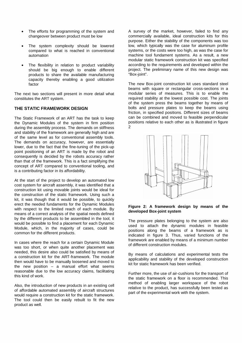
The new Box-joint construction kit uses standard steel beams with square or rectangular cross-sections in a modular series of measures. This is to enable the required stability at the lowest possible cost. The joints of the system press the beams together by means of bolts and pressure plates to keep the beams using friction, in specified positions. Different sizes of beams can be combined and moved to feasible perpendicular positions relative to each other as is illustrated in figure 2
Figure 2: A framework design by means of the developed Box-joint system
The pressure plates belonging to the system are also used to attach the dynamic modules in feasible positions along the beams of a framework as is indicated in figure 3. Thus, varied functions of the framework are enabled by means of a minimum number of different construction modules.
By means of calculations and experimental tests the applicability and stability of the developed construction kit for static framework has been verified.
Further more, the use of air-cushions for the transport of the static framework on a floor is recommended. This method of enabling larger workspace of the robot relative to the product, has successfully been tested as part of the experimental work with the system.

THE DYNAMIC MODULES
This section presents the Dynamic Modules. Some parts of the sub-systems presented in this section have previously been presented in [1]. The Dynamic Modules were designed so that an operator could attach them to the static framework manually. Seven different Dynamic Modules were developed, see figure 3.
Figure 3: The Dynamic Modules
In a normal case there would probably be only one or two Dynamic Module solutions chosen in an ART system. In this case, there was seven Dynamic Modules developed for being able to evaluate as many different solutions as was possible with respect to project time and budget. In general a Dynamic Module consists of a base plate and a top plate. In between there can be a parallel mechanical structure [11] or a serial linked structure. The Octapod, Tripod and Hexapod are examples of parallel mechanical solutions, and the Cradles are examples of the serial linked solution. The Carriage solution is a hybrid between serial- and parallel structure. The base plate is attached on the framework, and has therefore the same design as the Box-joints and is attached accordingly.
LOCKING MECHANISM
The locking sleeves are hydro-mechanical, which means hydraulic pressure in the system is only required when changing from unlocked to locked mode and vice versa. The hydraulics pushes a wedge between two states and thereby activates the mechanical locking effect. This movement is crucial so as not to affect the position of the legs in the Dynamic Module. Using the Hypus locking sleeves from the company ETP Transmission, made this possible.
This research has focused on using cheap off-the shelf components, preferably mass-produced for other purposes. This was however, not always possible, and some sub-components had to be developed in-house, such as the locking mechanisms for the ball joints.
THE CAPTO INTERFACE SYSTEM
At the top of the Dynamic Modules plate is attached an interface called a SANDVIK Capto. The Capto interface has several purposes, see figure 4. A primary function is for the robot to dock onto the modules. A secondary function is to attach the pick-ups that are holding the aircraft parts. A tertian purpose is for the Metrology probe to attach to the modules to calibrate their initial position. The Capto system is robust and has a repetitive accuracy of 2 µm and was originally designed for holding cutting tools in CNC machines, hence they are mass-produced and relatively cheap. The robot, the pick-ups and the Metrology Probe have a female Capto chuck. The robot chuck is locked automatically, whereas the probe and pick-up chucks are locked manually.
Figure 4: Three applications for the Capto System
THE PICK-UPS
After the robot has positioned the Dynamic Modules to an accuracy of 50 µm, the pick-ups are attached on the top-plate of a Dynamic Module. The important accuracy however is the datum point. A datum point is the position in Cartesian space that defines where the aircraft parts are to be located, or “picked up”, see figure 5. One issue is the fact that the position given by the robot during configuration of the Dynamic Module, ensures accuracy of the Capto interface and not the datum point.
Figure 5: The aircraft parts are attached on the datum points
DM´s positioned by the Robot
Datum point

Figure 5 shows the relation between the male Capto interface on the Dynamic Module (DM) that is position by the robot and the datum point that is attaching the aircraft part. This relation was calibrated using a Coordinate Measurement Machine (CMM). From the measurements the CAD model of the Pick-up was updated. The updated value is in fact the difference between the nominal configuration and the measured relation. As a result the male Capto position in Cartesian space was updated in the simulation model, and the DM was re-positioned slightly, to compensate for the difference between the digital model of the Pick-up and the physical one. This method gave the datum points good accuracy.
DUMMIES
Five of the eight DM’s were locked hydro mechanically. The other three was locked manually and was called Dummies. There were only enough resources to build one active Dynamic Module of each kind. The Dummies proved to work surprisingly well. Even though the Dummies were locked and un-locked manually, they where stilled configured by the robot similar to the active ones. In fact the same reconfiguration cycle as the hydro-mechanical solution was performed, but with manual lock/un-lock operations.
Having presented the building blocks of the ART system, the next section in this paper will go deeper into the integration of robots and metrology system that enables maintained accuracy in reconfiguration of the DM’s.
THE METROLOGY-INTEGRATED ROBOT CONTROL
Industrial robots today do not meet the accuracy requirements for aircraft automation. However, they are mass-produced primary for the automotive industry and are therefore much cheaper than other machines for automation, hence solving the inaccuracies would give us a low-cost machine for aircraft automation. One way to compensate for the lack of accuracy is to integrate the robot controller with a metrology system. This research has used the LTD800 from Leica Geosystems. The LTD800 laser tracker measures through an interferometric laser the distance to a laser prism. Positional accuracy is 10 µm per meter distance away from the tracker unit. The LTD800 is the next version of the LTD500 with an additional camera called the T-Cam. The camera measures orientation of a probe, using 10 LEDs. The T-Cam has a built in zoom lens, which is used into zoom in the probe to fill the image prior to processing it. The T-Cam gives an orientation accuracy of 0,02 degrees throughout the work volume of 15 m. The LTD800 is possible to be controlled over a normal Ethernet LAN using emScon, an embedded system control software. The IRB4400 Industrial robot
from ABB has a similar system called WebWare. Using emScon and WebWare, the tracker and robot are integrated by a Visual Basic program. In its current state, the integration is not a real-time system, and it communicates on the level of seconds. The topology of the system is shown in figure 6.
Figure 6: Topology over the Integration
Experiments proved that it was possible to position the robot to within 50 µm (square root sum of the three axis error). This interval could easily be changed. Several tests were done on 25 µm, but that sometimes caused oscillating behavior, since 2-3 m away from the tracker unit is the accuracy limit of the tracker unit. Normal use of the LTD800 is to use it for probing. The handheld probe is called the T-Probe. The T-Probe is much more convenient for probing instead of having to work with a small prism ball. In this research an additional Robot Reflector was developed, see figure 7.
Figure 7: A reflector attached on the robot
The Robot Reflector was designed using the same Capto system as for the Dynamic Modules. It contained 10 LEDs and it works the same way as the T-Probe. Using the Capto system for the Robot Reflector enabled probing of the initial state of the Dynamic Modules.

Figure 8: The coordinate systems and transforms
Reconfiguring a Dynamic Module involves friction. As mentioned earlier, modeling your environment is one approach to dealing with the stiffness and accuracy problems of articulated robots. This research, solving it by supervising inaccuracies, was successful, and the extra time to manipulate the Dynamic Modules, moving with friction, was just slightly longer. The calibrations and transforms, as shown in figure 8, is more in depth presented in [6] and [7].
OPERATION PLANNING
This paper so far has presented and discussed one philosophy to enable low-cost automation for aircraft assembly. We want to use industrial robots that are normally used in automotive industry, and although these robots do not have sufficient accuracy, they still are relatively cheap compared to other machines used in automation.
Today’s Industrial Robots are programmed by off-line systems. Although programming has now become object oriented rather than robot oriented, which essentially means you need not understand a specific robot language and programming is done by clicking on objects in a 3D graphical environment. But, comparing the different scenario for the manufacturing of cars with aircrafts; cars are built on the range of hundreds of thousands and aircrafts may be built in the range of a few thousands and often fewer. The simulation- and programming systems for Industrial Robots available today was brought about for car industry. In the scenario of building hundreds of thousands of cars, there is more time available for operation planning compared to building just a few aircrafts. Programming and operation planning must be simplified in a low-volume production scenario, such as for aerospace.
This research has included studies to simplify programming of robots by moving up towards the process-oriented abstraction level using V5Robotics
from DELMIA. A process naming of the frames (robot locations) was developed. DELMIA and many other simulation systems use the standard language XML. Normally XML is stored in the background of a simulation and not until a specific robot language is selected in the OLP (offline programming) module of the simulation system, is the XML then transformed (parsed) to a robot specific code. In this research, the parsing was never performed in the simulation software. Instead the XML code was downloaded to the integration software in the workshop. The integration software interpreted the processes from the XML directly, hence parsing it to robot operations, operations for the operator, measurement tasks for the tracker etc.. It is important to realize that this system is not just a robot cell. It includes several tasks that are not robot specific. This method also allowed the operator to execute any sub-process along the sequence of operations in the task list that was presented exactly the same in the integration software as in the simulation environment. This method of programming was possible to implement by having only one small generic program in the robot controller, hence no dedicated robot code for each sequence of operations.
By using a metrology system to guide the robot to high accuracy, no normal robot calibration of the system was required when going from the offline-programming system to the workshop floor. The only calibration performed was the Probing of Dynamic Modules presented earlier. This indeed simplified implementation of changes that was brought back to the simulation model from physical experiments.
RESULTS
This section will discuss some interesting issues that arose during the final implementation of the demonstrator and describe measures undertaken to solve them.
STATIC FRAMEWORK
The ideas of constructing the demonstrator with modular beams went better than expected. From the stage of having beams on the floor until the complete framework according to figure 1 took one day. That was accomplished without using a crane. Instead the winch system on top of each vertical beam was successfully used. There where some difficulties to model the mechanical limitations in the digital model of the Dynamic Modules, which resulted in some late changes in the framework that easily could be modified thanks to the ability to re-build.
DYNAMIC MODULES
The Dynamic Modules had some issues in the final testing. The ball-joints had some axial movements

during locking. Where a wedge is pushing the ball onto a metallic ring, movements occur during locking. This could be a problematic case, since the robot ensures 50 µm only prior to locking. When locking occurs, the robot cannot compensate anymore. Two different approaches to solve this problem were tested. The first one is to lock each individual locking sleeve in a certain order. If the ball joint is locked first, the movement in the ball will be taken up in the rest of the module. The second approach is to measure the position of the robot after locking has occurred. This way the error due to locking is identified. In this case, the module is first un-locked, and then re-adjusted by the robot, where the error during locking is added to the first position. When locking is done again, the module will “lock itself” to the right position.
TRANSFORM CALIBRATION
Another issue in the final testing was the calibration of the metrology system to the robot. To calibrate the tracker relative to the robot, a sequence is performed where the robot is moved to several locations with changes in orientation. Locations are stored both in tracker and robot and calculated. More information about this can be found in [7]. Due to the relatively bad absolute accuracy in the robot, the transformation will have an error. Look for the dotted lines in figure 10. When the robot is iterated down to a square root sum off 50 µm, the robot reference values are way of. The x reference, for example of the robot in figure 10, shows 1.6 mm off.
Figure 10: The robot and tracker position in a high-accuracy point
It is important to realize that the transformation error does not affect the absolute accuracy of the integration itself. The integration is controlled in relation to the tracker coordinate system, hence “what you see is what you get” is the case here - at least as well as the tracker can provide us regarding accuracy.
REFLECTOR CALIBRATION
As shown in figure 4, the Sandvik Capto interface on the reflector was used for probing the initial state of the Dynamic Modules can in addition could be attached on the robot during metrology-integrated robot control. The calibration of the female Capto on the probe did not fully meet the expectation. When docking the robot to the Dynamic Modules a clearance of 1 mm in the entrance was required. Due to some misalignment in calibration, docking in the preliminary testing was for this reason sometimes not possible. This was later solved by calculating the difference in the measured value between probed location and docked location. The difference was added to the docking position. The result was indeed satisfying and not one docking was missed after this point.
UN-DOCKING
The metrology system only guides the robot to its final positional accuracy at a location, not on the trajectory between two locations. And due to the rather low robot accuracy the robot risk applying un-wanted forces during un-docking. The forces may be applied between the inner side of the female robot chuck and the male Capto interface on the DM. As long as this bending movement is lower than the stiffness limits in the DM, nothing happens. In some tests the robot did push too hard and caused a small deviation of the datum point. This was rather easily solved by moving the robot in its TCP coordinate system by the ABB RAPID command: RelTool. RelTool moves linearly in tool coordinates. Although the robots have bad absolute accuracy, they are good at moving relatively to a location they have been in before, in this case the docked position. A second approach to solve this problem was tested in addition. This was done by making the robot less rigid by using something called soft-servo. The disadvantage of using soft servo is that when the undock sequence is complete the robot sometimes makes big movements that are hard to control. Therefore it was better to make the undock movement as linear as possible to avoid unwanted forces on the Dynamic Module.
FINAL REMARKS
Striving towards low-cost automation, it is imperative to use as much existing components as possible instead of making everything in-house to get it right. The challenge was to design systems with novel ideas from what is already available on the market. This could keep cost down, and quality ensured, which was important in the hunt for errors and causal effects when putting sub-systems together. Furthermore, buying existing components will also save lead-time. Excluding these facts may lead to one of the major problems in automatic assembly systems, especially for complex products such as airplanes, where assembly systems is

common to be vastly expensive and suffer from large technical risk and are in-flexible. Again, this is what we call “Monumental Automation”.
CONCLUSION
This paper presented the final results of the evaluation and testing of an aircraft assembly demonstrator that was built at Linköping University as a result of a three-year project funded by the European Commission. A robot has successfully reconfigured Dynamic Modules to 50 µm mm accuracy. Some modules did move slightly during module locking, but several methods have been investigated and tested to deal with this problem. Although the metrology system used for this research is somewhat overqualified, it has given us good quality in metrology feedback necessary to reach aircraft requirements on positional accuracy. Future research at Linköping University will investigate new low-cost solutions for metrology-integrated robot control. Promising efforts are now being made in also integrating drilling and fastening functions into a complete automatic low-cost system.
REFERENCES
1. Kihlman H., “Affordable Reconfigurable Assembly Tooling - An Aircraft Development and Manufacturing Perspective”, Licentiate Thesis No. 980, LiU-TEK-LIC-2002:53, Department of Mechanical Engineering, Linköpings Universitet, SE-581 83 Linköping, Sweden, ISBN 91-7373-460-8, 2002
2. Lindqvist, R., Eriksson, I., Wolf, M., “Orbital Drilling of Sandwich Constructions for Space Applications”, SAE Aerospace Automated Fastening Conference & Exposition, 2001
3. Kihlman, H., Eriksson, I. and Ennis, M., "Robotic Orbital Drilling of Structures for Aerospace Applications", SAE Aerospace Automated Fastening Conference & Exposition, October. 1-3, 2002
4. Lindqvist, R. and Kihlman, H., “Orbital Drilling - Implementation and Evaluation”, SAE Aerospace Automated Fastening Conference & Exposition, Sept. 20-23, 2004
5. Kihlman, H. and Engström, M., "Affordable Reconfigurable Tooling", SAE 2002 Transactions Journal of Aerospace, ISBN: 0-7680-1285-6
6. Kihlman, H. and Loser, R., "6DOF Metrology-integrated Robot Control", Aerospace Automated Fastening Conference & Exhibition (Aerofast); September 8-12; Palais des Congrès; Montreal, Quebec; Canada, 2003
7. Kihlman, H., Sunnanbo, A., Loser, R., Von Arb, K., Cooke, A., "Metrology-integrated Industrial Robots – Calibration, Implementation and Testing", 35th International Symposium on Robotics, Paris-Nord Villepinte, France, March 23-26, 2004
8. Helin, P., Jerregård, H., Robertson, A., and Snell, J., "Technologies that make a robot reach Absolute Accuracy", Proceedings of the 33rd International Symposium on Robotics, October 7-11, 2002
9. Dégoulange, E., Dachez, P., Pierrot, P., Prat, P., "Robust Design of Independent Joint Controllers with Experimentation", IEEE Transactions on Industrial Electronics, vol. 40, No. 4, August, 1993
10. Webb, P., Eastwood, S., Chitiu, A., Fayad, C., McKeown, C., “The Design and Realisation of a Flexible Rapid Assembly Aero-Structure Manufacturing Cell – A simulation Driven Approach” Aerospace Manufacturing Technology Conference & Exhibition; September 8-12; Palais des Congrès; Montreal, Quebec; Canada, 2003
11. Askbrink, P., “Optimization of Parallel Mechanical and Adjustable Assembly-jig”, LiTH-IKP-Ing-Ex-02/14-SE, June 2002
CONTACT
Henrik Kihlman Department of Mechanical Engineering Linköping University Phone (+46) 13-288 974 E-mail: [email protected]
Gilbert Ossbahr Department of Mechanical Engineering Linköping University Phone (+46) 13-281 129 E-mail: [email protected]
Magnus Engström SAAB Aerostructures Phone (+46) 13-184 585 E-mail: [email protected]
John Anderson Advanced Technology Centre BAE SYSTEMS E-mail: [email protected]
ABBREVIATIONS
ADFAST – Automation for Drilling, Fastening, System Integration and Tooling
ART – Affordable Reconfigurable Tooling
DM – Dynamic Module