losmmilm - federation of american scientists
TRANSCRIPT

LA--11789-MS
DE90 011266
High Explosives SkidImpact Initiation Study
Armando S. Vigil\amesM. BunchDwight L. JaegerPaui D. SmithErnest E. Abeyta
This report was preparedas an accountof work spa.sorcdby an agencyof the United StatesGovernment. Neither the United States Governmelttnor any agencythereof,nor iiny of theiremployees,makesany warranty, expressor implied, or assumesany legal liability or rc.sponsi-bility for the accuracy,completeness,or usefulnessof any information,apparatus,product,orprocessdisclosed,or representsthat its use would not infringe privately owned rights. Refer-enceherein to any specificcommercialproduct,process,or serviceby trade name, trademark,manufacturer, or otherwisedoes not necessarilyconstituteor imply its endorsement,rccom-mcndation,or favoring by the United States Governmentor any agency thereof. The viewsand opioiosx of authors expressedherein do not necessarilystate or reflect those of theUnited StatesGovernmentor any agencythcr~f.
Losmmilm Los Alamos National LaboratoryLos Alamos, New Mexico 87545

CONTENTS
ABSTRACTI. INTRODUCTION” : : : : : : : : : : : : : : : : : : : : : : : :II. APPROACH111. EXPERIMENTAL” RESULTS : : : : : : : : : : : : : : : : : :
A. Go/No-Go Detonation Criteria. . . . . . . . . . . . . . . .B. Air Gun Data . . . . . . . . . . . . . . . . . . . . . . . . .C. Drop Tower Data . . . . . . . . . . . . . . . . . . . . . . .D. Infrared Detectors. . . . . . . . . . . . . . . . . . . , . . .
IV. COMPUTER MODELS AND SIMULATIONS . . . . . . . .A. EXPLO Thermal Analysis . . . . . . . . . . . . . . . . . .B. DYNA3D Stress Analysis . . . . . . . . . . . , . . . . . . ,C. ABAQUS Heat Transfer and Stress Analysis . . . , . . . .
v. SUMMARY AND CONCLUSIONS . . . . . . . . . . . . . . .REFERENCES . . . . . . . . . . . . . . . . . . . . . . . . . .
LIST OF FIGURES
12
345
6
7
8
9
Schematic diagr~m of the HE skid impact initiation experiment.Impact velocity and corresponding drop height capabili~yof the155-mm air gun. . . . . . . . . . . . . . . . . . . . . . . . . . . ,Original and-modified projectile assembly designs. . . . . , . . 6Schematic diagram ofvertical drop test configuration. . . . . . 8Finite element mesh of the projectile assembly as it impacts aninclined aluminum plate. . . . . . . . . . . . . . . . . . . . . . . . 13Deformation and maximum principal strain of l-inch diametersample impacting a target plate inclined 45 degrees. . . . . . . . 16Deformation and maximum principal strain of 10-inch diametersample impacting a target plate inclined 45 degrees. . . . . . . . 17Deformation and maximum principal strain of l-inch diametersample impactin a target plate inclined 30 de ees. . . . . . . . 18Deformation anf rmaximum principal strain o 3-inch diametersample attached to a modified proj~ctile impacting a target plateinclined 30 degrees. . . . . . . . . . . . . . . . . . . . . . . . . . . 19
LIST OF TABLES
1 PBX 9404 HE Skid Impact Ignition Data . . . . . . . . . . . . 9~ Material Properties used in DYNA3D Skid Impact Analysis . . 14
v

HIGH EXPLOSIVES SKID IMPACT
INITIATION STUDY
by
Armando S. Vigil, James M. Bunch, Dwight L. Jaeger,Paul D. Smith, and Ernest E. Abeyta
ABSTRACT
The objective of this study was to develop a better quantitativeunderstanding of explosive behavior under skid impact conditions.We evaluated the effects of sample weight, impact velocity, contactsurfacearea at impact, target surfaceroughness,and target materialon the skid impact HE ignition threshold. We also quantified theeffects of two parameters that had never been fully investigated inthe standard skid impact sensitivity test: explosive sample size andangle of incidence. These parameters were studied experimentallyby conducting a series of tests, and analytically, with a number ofone-, two-, and three-dimensionalcomputer models. This study isthe first phase in a program to measurethe transientheat producedin the ignition of a high explosive sample as it impacts an infrared(IR) transmissive target. We will use the experimentally deriveddata to enhanceour ability to predict the onset of ignition in impact-heated high explosives.
I. INTRODUCTION
The ignition of high explosives under skid impact conditions has never been
satisfactorily understood. It is not entirely predictable. The results of our ini-
tial tests and structural analyseson this project indicate that a small-diameter
secondary high explosive hemisphere may ignite more readily at lower impact
velocities than at high ones. At lower velocities the sample holds together long
enough for heat from combined compression, friction, and shearing forces to
build to ignition. This is an important safety issue. Safety is the principal
1

motivation behind the work done in this project. Furthermore,a better uncler-
rtanding of the mechanism may affect the design of some weapons in extreme
en~’ironment.s,such as artillery-fired projectiles and earth pcnetrators.
Von Hone, LLNL, has demonstrated the feasibility of the measurement
of the infrared emission of radiation from shocked explosives using infraredequipment.1 He observed chemical hot spots that are postulated as nucleation
sites for buildup to detonation. However,while we are interested in investigat-
ing the threshold of igniticm, Von Hone confines his work to shock heating atl.~ry high pressures. His pressuresare prodllccd by normal impact velocities
twmty times that of our drop tower or projectile launchercapability. Dyer and
Ta~.lor,Al\’RE, and Randolph, Hatler, and Popolato, L.41JL1have investigated
the friction-heating mechanism in secondary high explosi~’esat their ignitionthrcsholds,2’3 They investigated the effects of explosive weight, drop height,
target thermal conductivity, and surface roughness on HE initiation. We in-
tend to probe further into the heat buildup mechanism that determines the
go/no-go ignition threshold. We postulate that it occurs in the thin region of
impact-heated high explosive at the HE-target interface. We plan to use our
infrared cq~lipmentto investigate what occurs in this region.
II. APPROACH
In the standard skid tests,~a bare explosive charge hits a rigid surface at an
oblique angle. This simulatesthe condition where a bare charge is accidentally
dropped. These tests have only been done with large samples, between 9 and132 kg in weight, at incident angles of 14 and 45 degrees. The variables are
drop height, angle of impact between target and explosive, and target surface
conductivity and roughness. We quantify these variables as well as the effect
of small sample size in the work described here.
Our approach in this program will be to impact small high explosive charges
onto infrared-tranwnissive targets and measure the temperature at the HE-
target interface. We use two methods to achie~”eimpact: a 155-mm diameter
projectile launcher powered by compressed air, and a 46-meter drop tower.
Both facilities are located at K-Site (TA-11). A schematic diagram of the HE
impact initiation experiments is shown in Fig. 1. The high explosive sample
impacts the window, either salt (NaCl) or sapphire, at an oblique incident an-
gle. Two InSb infrared detectors with selected band-pass filters will be used
2
PRQKCZ’UZI HE
= q!~%w----------------
D:HEAM
(..........................‘SPLnTER:
\\
INFRAREDDm’ErmRs~ m
Fig. 1. Schematic diagram of the HE skid impact initiation experiment.
to record the impact-induced temperature rise through the window using an
appropriate mirror/beam splitter configuration. If the air gun is used, the pro-
jectile assembly is deflected into a catch tank after bouncing off the target. The
signals from both detectors will be processed to obtain a transient temperature
response curve.
III. EXPERIMENTAL RESULTS
A. Go/No-Go DetonationCriteria
~~~eestablished a go/no-go detonation criteria by measuring the cwerpres-
suresproduced from l-inch diameter hemispheresof PBX 9501 high explosive.
PBX 9501 is a plastic-bonded secondary explosive composed of 95 wt% HMX,~.j ~t~OEst,ane,ad 2.5 wt~o BDNPA/BDNPF. We ignited the h~mispheres
using exploding bridge wire (EB-1) detonators cemented to the flat face of each
9-gram charge. The pressure gauges used were Endevco 851OB piezoresistive
transducers mounted to 4-inch square aluminum plates. We measured aver-
age peak reflected pressuresof 1269 and 6.9 psi for the gauges located 11 and4Z in~es from the HE, respectively. No pressure was recorded on any of the
gauges when projectiles without HE were fired from the air gun onto a target
3
plate. \\re can readily clistinguis~ between the o~.crpressurefrom the detona-
tion of 9 grams of HE at the target surface and the air gun’s muzzle blast. We
do not plan to test HE samples smaller than 9 grams.
B. Air Gun Data
our air gun projectile assembly cmsists of a l-inch diameter hemisphere
sample glued to a -l-inch high cone of 900-10 inert HE, attached to a 4-inch
long, 155-nml diameter steel c~”linder.The mass of the projectile assembly, 11
kg, approximates the mass of the standard LLNL-Pantex skid sensitivity test
specimen.5 The air gun is enabled for firing by inserting the projectile assembly
into the gun through the breech end and installing the breech closure. Theprojectile acts as a valve and seals off the open end of a 6-inch diameter high
pressure hose. When the end of this hose is sealed, a large tank, attached to
the other end, may be pressurized with an air compressor. The projectile is
launched remotely by using a solenoid valve to inject a burst of air between it
and the closed end of the gun. This pushes the projectile past the hose opening
and allows the high pressure air to rush in and eject the projectile. It travels
about three feet horizontally before it impacts the target.
we ha}.esuccessfullypropelled n-kg projectiles to muzzle Velocitiesranging
from 5 to 35 m/s. We measurethe projectile velocity using magnetic proximity
switches mounted on the muzzleend of the air gun, the Spin Physics 2000 High
Speed Video System, and high-speed photography. The projectile velocity has
been correlated to tank air pressure and equivalent drop height, a standard
measureof comparing the relative safety of high explosives. The data obtained
using these three velocity measuring systems is shown in Fig. 2. We have
exceeded the maximum \-elocityattainable on the 46-meter drop tower and can
go to higher pressures/velocities if necessary. A catch tank for the projectile
was fabricated, installed, and tested. The catch tank allows us to retrieve and
reusethe undamaged projectile components with a minimum of reconditioning.
The air pressureversusprojectile velocity data shown in Fig. 2 was obtained
using l-inch diameter wax or explosive simulanthemispheres. Our initial tests
using live HE were done using PBX 9404 samples. PBX 9404 HE is a pla,stic-
bonded secondary explosive composed of 94 wt% HMX, 3 wt% nitrocellulose,
3 wt% CEF, and 0.1 wt% DPA. We used PBX 9404 instead of PBX 9501HE samples because the 50% drop height of PBX 9404 is one-sixth that of
4

L3c
6C
4C
~
52(3Q
?n
Ic.2n
● SPIN PNVSICS 5““
❑ PROXIMITYSWITCH
■ PHOTOGRAPHY1
t
o 20 40 60 80 100 120
Pressure (psi)Fig. 2. Impact velocity and corresponding drop height capability ofthe 155-mm air gun.
PBX 9501 HE. The 50% drop height is the estimated median height, where
the probability for an e~”entis one-ha.lf.e The samples were fired onto salt
windows bonded to l/4-inch thick plywood boards. The boards were bolted to
a large steel shot stand at a 45 degree angle to the initial projectile direction.
Because we were not able to obtain ignition with the salt/plywood target,
we replaced the plywood board with a sturdier target support made of 3/8-
inch thick aluminum plate. \\reused epox}- adhesive to bond sheets of 80-grit
garnet paper (sandpaper) to 4 x 11 inch plates of aluminum bolted to the shot
stand. The 50$%0drop height of a 10-inch diameter hemisphere of PBX 9404
HE on a sandpaper target at a 45 degree incident angle is 4 feet.4 Surprisingly,
we did not obtain ignition of any of the l-inch diameter samples, even when
impacting PBX 9404HE on sandpaper at a velocity that corresponds to a drop
height of 115 feet. In an effort to obtain ignition we also fied l-inch diameter
hemispheres of PBX 9404 and PBX 9501 HE at glass, salt, and fuzed-quartz
targets bonded to 3/8-inch aluminum plate at velocities that correspond
drop heights ranging from 17 to 6’i feet. There was no evidence of ignition
any of these shots.
toin
5

Fig. 3. original and modified projectile assembl~.designs.
D~-erand Taj.lor determined that it takes about 0.5 ms for heat from fric-
tion, compression. and shear mechanisms at the impact interface to build to
ignition.2 Our initial three-dimensionalstructural anal>-sesof the impact e~.ent
indicate that a l-inch diameter explosi~.ehemisphere breaks apart 0.2 to 0.5
ms after impacting a target plate inclined 45 degrees to the angle of incidence.
Our analj.ses re~.ealthat impacting a plate set at a 30 degree angle of inci-
dence allows more time for heat buildup. Howe\.er,the analyses also revealed
that when the target plate is inclined 30 degrees or less to the initial projectile
direction. the forward end of the inert support cone strikes the target early
enough that it interfereswith the impact of the sample hemisphere. \Veelimi-nated this interference by modif].ing the design of the projectile assembly. It’e
machined a flat surface on the side of the inert cone and bonded the l-inchdiameter hemispheres to this surface. The modified projectile assembly, used
in the shallow incident angle tests, is shown in Fig. 3 along with the original
projectile assembly design.
To determine if this new test configuration would perform as expected, we
fired two shots with l-inch diameter wax hemispheresbonded to the modified
inert cones. The sandpaper-covered aluminum target plate was attached to the
shot stand at a 30 degree angle of incidence. We measuredprojectile velocitiescorresponding to drop heights of 18 and 38 feet. There was a ?-inch long
wax smear on each sandpaper target after the tests. From the location of the
smear we feel that we can hit our target accurately because there is little or norotation of the projectile when it exits the gun.
~~refired the ~~rojectilewith a l-inch diameter PBX 9404 explosive hemi-
sphere bonded to the flat surface of the inert cone inta a sandpaper co}-ered
aluminunl target plate set at a 30 degree incident angle. The impact \*elocity
was 8.5 m/s, corresponding to a drop height of 12.1 feet. We did not ob-
tain ignition or any measurable overpressure. Because of cost and schedule
constraints, we have not conducted tests at higher impact velocities.
\Veperformed a spectroscopic analysis of the HE smear on the plate and
found no evidence that the PBX 9404 HE had been heated past the beta-to-delta solid-to-solid phase transition temperatureof 190”C. How;vcr, we found
hydrocarbon-based oil ccmtaminationon the target. The oil may have come
with the compressed air released from the gun muzzle It may affect heat
transfer or prot”ideheat sink effects at the HE/sandpaper interface and hinder
HE ignition. Dyer and Taylor report that initiation normally observed on adry surface docs not occur when water is present.2 We need to eliminate all
oil contaminants in our air gun shots if we hope to obtain relevantskid impactHE ignition data,
C. Drop Tower Data
We cannot test explosi}.es larger than a few grams at the air gun facility
because of the proximity of support equipment and structures. The K-Site
drop tower facility allows us to drop large, 10-inch diameter high explosive
charges from a height of up to 46 meters. Most skid sensitivity data published
in the literature were obtained using this and similar drop towers.4’5 The data
are obtained by allowing an uncased hemispherical charge to drop from the
tower octo a rigid target at an oblique angle. A schematic of the vertical drop
test configuration is shown in Fig. 4. Results reported are the drop heightthat produces e~.entsin 5070 of the trials and the average overpressure. In
another \“ersionof the test, the hemisphericalcharge is allowed to swing down
in a hamcss on the end of a cable and strike a rigid horizontal target at a
predetermined angle. This version was not used for the work described in
this report. We used the vertical drop test to determine the 50% drop heightof progressively smaller explosive samples when we were not able to obtain
7

TLINE OF DROP
SOILER PLATE
I.-
Fig. 4. Schematic diagram of vertical drop test configuration.
ignition of l-inch diameter PBX 9404 HE hemispheresusing the air gun.
In this test series, 6-, 3-, and l-inch diameter samples were dropped. The
6- and 3-inch diameter explosive sarr.piesare bonded to 1/2- and 3/8-inch
thick ,Micarta disks, respectively. The disks were drilled and tapped at thecenter to hold a lanyard by which the specimens were suspended from the drop
releasemechanism. Becauseof their small size, we mounted the l-inch diameter
sampleson either HE simulantcones or l-inch diameter wood dowels. We used
guide cables for the l-inch diameter drops. The guide cables ensureaccuracy in
hitting the target and greatly restrict rotation of the specimens upon impact.
In all cases the targets are 80-grit garnet paper bonded with epoxy adhesive to
l/4-inch thick aluminum plates. The target plates are supported on a 5 footsquare by 4.5-inch thick steel target stand inclined 45 de~ em to the vertical.
The 50% &up height for the standard 10-inch diameter hemispheres of
PBX 9404 HE, determined from tests conducted several years ago, is 4 feet.
Assuming a IGgnormaldistribution for the go/n~go events, the 50% drop height
of the 6-inch specimens is 5.3 feet.e Impact spot diameterson the charges and
targets were from 5/8 to 3/4 inch for the no-goes that remained intact. Not
8

Table 1. PBX 9404 HE Skid Impact Ignition Data
Minimum
Test Total Charge Incident 50% Drop Max.Height EXPLO Ign.
Config. Xlass(kg) Dia.(in.) Angle(deg) Height(ft) Tested(ft) Height(ft )
~’crt.Drop 8.7 10 45 4.0 15 1.8
\’ert.Drop 2.0 6 45 5.3 6.3 5.2
Vert.Drop 0.3 3 45 23.7 50 19.8
J’ert.Drop 0.6 1 45 15 84
Air gun 11 1 45 115
Air gun 11 1 30 12.1
“This drop height W= calculated using the additional 600 g weight of the inert cone thatwas attacked to the sample.
all the reactions were high-order detonations. The 507’odrop height of the 3-
inch diameter PBX 9404 HE samples is 23.7 feet. We measured impact spot
diameters from 3/8 to 1/2 inch for the no-goes that remained intact in thisseries. Most of the reactions were low-order partial detonations. The l-inch
diameter HE samples did not ignite at drop heights up to 15 feet, despite
the guide cables and the additional weight of the inert cones or wood dowels
attached to them. We have not been able to test at higher drop heights.
Remember that we were not able to detonate l-inch diameter PBX 9404 HE
hemispheres using the air gun at an equivalent drop height of 115 feet. As
before, in the events where no reaction occurred, we conducted a spectroscopic
search of the sandpaper targets for beta-to-delta phase change in the HMX
crystals of the PBX 9404 HE. We found no evidence that the l-inch diameter
samples had been heated past the phase change temperature of 190”C.
A summary of the air gun and drop test data is given in Table I. Note that
the 5070 drop height of the l-inch diameter hemisphereshas not been deter-
mined. To accomplish the remainingobjectives of this program, we must deter-
mine the minimum HE sample size that can be consistently initiated through
skid impact. Because of the difficulty in igniting the l-inch hemispheres,we will
drop either 3-inch diameterhemispheresfrom the toweror use the air gun to fire
l/2-inch high x 3-inch diameter spherical segmentsonto infrared-transmissive
targets.
9
I). InfraredDetectors
Our HE skid impact initiation program requires that we use suitable tem-
perature measuring devices. We ran a model parameter study to optimizethe detc~tor wavelength bands for a two-color infrared pyrometer for use in
the temperature range 150 to 300”C, We evaluated the suitability of various
detectors for use in the selected wavelength range, given the expected targetparameters. }Ve determined that liquid nitrogen cooled InSL or gold-doped
Ge should gi~.eusable signal-to-noise ratios for the proposed experiments. Wetested a borrowed gold-doped Ce detector on a simulated target in an oven. It
gave an easily detectable signal at 150”C. Because InSb is supposed to give a
factor of tcn bett,;r sensitivity than gold-doped Gel we purchased a pair of InSb
detectors mounted on Dewars with appropriate band-pass filters. We installed
them in camera mounts with provisions for aiming and alignment through BaF
lenses. J\redesigned and built a system to calibrate the detectors by producing
pulsed thermal signals using an oven with a shuttered opening.
\\-ecalibrated the InSb pyrometer by measuring the ratio of the responsesof t]l.~tl~~odetectox”saillled at a source heated to various temperatures in the
range of interest. Using various simulated targets, we evaluated the pyrome-
ter’s sensiti~-ityand temperature resolution in measuring the temperature of a
simulated “hot spot” surrounded by a region of 10WCYtemperature. We should
be able t6 obtain transient temperature response measurementsfrom the sam-
ple/window interface. By comparing the response mca.surementsof inert and
reactive material, we hope to learnmore about the melt phase that we postulate
to occur in the skid impact ignition of high explosives.
IV. COMPUTER MODELS AND SIMULATIONS
Three computer codes were used in our modeling effort. They are EX-
PLO, DYNA3D, and ABAQUS. The EXPLO thermal analysis cocie,7 which
includes a subroutine that models the skid impact of explosives on different
ta~get slabs, allows us to predict HE ignition. The DYNA3D code8 allows
nonlinear dynamic analyses of structures in three dimensions. The ABAQUS
codeg allows fully coupled temperature-displacementanalyses to predict mate-
rial deformation and HE ignition.
10

A. EXPLO Thermal Analysis
EXPLO was written by D. L. Jaeger and A. S. Vigil. It uses the finite
difference method to calculate temperature fields and times to initiation for ex-
plosive materials.7 The code is one-dimensional and is programmed for carte-
sian, cylindrical, and spherical coordinates. Temperature-dependent proper-
ties, phase changes, and multiple heat source terms use Nth-order Arrhenius
kinetics for each material component. To predict the initiation of high explo-
sives caused by’ skid impact, EXPLO contains a subroutine that computes the
energy generated by a sliding surface as a function of several variables and
time. These variables are drop height, weight, shear strength, and skid angle.
EXPLO uses Randolph et al.’s definition of heat flux generated at the sliding
surface between the HE and the target slab.3 The flux is calculated as
q = poV/J, (1)
where p is the apparent coefficient of friction (equal to the ratio of tangential
to normal contact forces), a is the normal contact presslwe (in this case equal
tu the plastic flow stressof the explosive), V is the sliding velocity, and J is the
conversion factor from mechanical to thermal units.
We used the EXPLO code to determine the minimumdrop height to ignition
for different weights of PBX 9404 HE dropped on an aluminum plate covered
with sandpaper. The weights correspond to different diameter hemispheric
test samples. For these calculations we assume the sandpaper is 0.5-mm thick,
with a density of 0.99 g/cc, a heat capacity of 0.25 cal/g/° C, and a thermal
conductivity of 0.028 cal/s/cm/°C. We use PBX 9404 HE shear strengths of2.oe09°and 2.6e08 dynes/cm2, at temperatures of 20 and 331”C, respectively.
We calculate that 10-, 6-, and 3-inch diameter hemispheresof PBX 9404 HE
dropped on sandpaper targets at a 45 degree incident angle would ignite at
minimum drop heights of 1.8, 5.2, and 19.8 feet, respectively. The test data
from Table I show that the corresponding 50% drop heights are 4, 5.3 and 23.7
feet, respectively.
If no inert cone or additional mass is attached to the l-inch diameter hemi-
spheres, we calculate a minimum drop height to ignition of 47 feet. If a 600-g
inert cone is attached to the PBX 9404 HE hemisphere, we calculate a mini-
mum drop height of 8 feet. We did not obtain ignition of the l-inch diameter
hemispheresamples in our drop tower tests, even at a drop height of 15 feet. If
11

the sandpaper target ASinclined 30 degrees to the vertical, wc calc~datea nlini-
mum drop height to ignition of 14 feet for the l-inch diameter hmnisphere/inert
cone assembly. We have no drop tower or air gun data above 12.1 feet for a
target set at a 30 degree incident angle.
The skid inlpact contact area must be greater than a certain minimum size
to provide the inertial and thermal confinement necessary for ignition. Dyer
and Taylor2 report that a contact area of at Ie.a.st1 squme inch is re,l,uiredtoproduce a high-order detonation through skid impact. Their experiments with
l/2-inch cubic samples resulted in only partial explosions. Because EXPLO
is a one-dimensional code, it cannot account for the change in contact area
when different diameter HE samples skid onto flat targets. We need to usc
a two- or three-dimensional code to mo flel the contact area properly. It is
especially important to do this when detilingwith sm~~lHE samples where the
skid impact spot diameter might be less than that required for detonation.
B. DYN’A3D Stress Analysis
\\Tcdid a seriesof three-dimensionalstructural analysesusing the DYNA3D
computer code to quantify the extent of HE breakage with time upon im-
pact loadiag. DYN.+3D is an explicit three-dimensional finite element code
for analyzing the large dynamic response of inelastic solids and structures.8
The DYNA3D version that we used was written by J. O. Hallquist and R. G.
Whirley, LLNL. The three-dimensionalmeshes were made with the ESCHER
and PATRAN codes. ESCHER is an in-house finite element mesh generator\vrittcnbv JITOR. Oakesolo PATRAN is a pre- and post-processing code written
and maintained by PDA Engineering.11 The DYNA3D code generates a bi-
nary plot file that can be viewed using TAURUS, an interactive post-processor
for the analj”sisof three-dimensionalcodes.12 TAURUS ~raswritten by B. E“
Brown and J. O. Hallquist, LLNL.
Figure 5 shows our finite element mesh of the projectile assembly before
it impacts a 3/8-inch thick x 4-inch wide x 10-inch long aluminum plate set
at an incident angle of 45 degrees. The projectile assembly consists of a 1-
inch diameter hemisphere of P13X 5404 HE bonded to a 900-10 inert cone,
which in turn is attached to a 155-mm diameter steel cylinder. The mesh is
made up of 8-node solid hexahedron elements with sliding interfaces between
the hemisphere outer surface and the front surface of the plate. We set the

Ill----l
Fig. 5. Finite element mesh of the projectile assembly as it impactsan i:]clined aluminum plate.
coefficient of friction between these two surfaces to 0.4. We also used fixed
interfaces to tie the coarse mesh of the cone to the much finer mesh of the
hemisphere.
11’eused a strain-rate-dependent isatropic plasticity material type for the
HE and kinematic hardening elastic-plastic material type for the other ma-
terials. The material properties are shown in Table II. In the strain-rate-
dependent model, a load curve is used to describe the yield strength, Co, as a
function of effecti}-e strain rate, ~, where
(2)
The prime denotes the deviatonc component. The yield stress is defined as
U!4= (70(q + EhP’, (3)
where ?’ is the effective plastic strain and Eh is given by
E~ = EEJ(E – E,). (4)
13

Table 2, Material Properties used in DYNA3D Skid Impact Analysis
Property PBX 9404 900-10 Inert Aluminum Alloy Soft Steel
Density 1.84 1.84 ge~ 8.0
(g/cc)Young’s hlodulus 6.8 6.8 70 200(GPa)
Poisson’s Ratio 0.30 0.30 0.33 0.33
Yield Stress *a 62 276 376
(MPa)
Hardening Modulus 10 10 700 2000(LIPa)
‘FOCeffective strain rates of 0, 3000, and 3.0e06 s-’, the yield strength of the IIE is 7, 62,and 500 MPa, respectively.
We do not hay-eaccurate \“alues for the properties ,~fi’BX 9404 HE at ~x-
tremely high strain rates. This should be tti!wninto account when considering
the results of this anal~-sis. Data obtained using our high-speed video system
in subsequent tests will be used to improve our material models. These initial
anaiyses are done to compare the effects of using different size samples and
slightly different geometries in our tests, and not necessarily to generate an
absolute description of the material behavior.
We fixed the outer edges of the plate and set the impact velocity of the
projectile assembly to 7.67 m/s. This corresponds to a drop height of 9.9 feet.
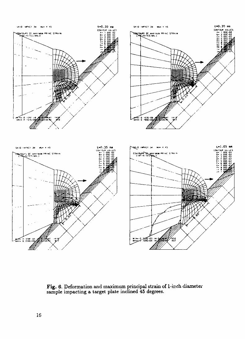
Figure 6 shows the deformation and maximum principal strain contours in a
sequence of selected times after a l-inch diameter PBX 9404 HE hemisphere
impacts an aluminum piate inclined 45 degrees to the initial projectile direc-
tion. The figure shows that 0.2 rnsafter initial contact is made the maximum
principal strain exceeds 1%, our chosen failure criteria, in almost half of the
sample. Even after 0.35 ms, the maximum diameter of flattened material is
less than l/2-inch. Our drop test data indicate that l/2-inch is the minimum
impact spot diameter required for high-order detonation. Although we con-tinue the analysis until large HE deformations are shown, it is not likely that
the specimen will remain intact for 1.05 ms. Figure 7 shows the deformation
and maximum principal strain contours in a sequence where a 10-inch diame-
14

ter PBX 9404 HE hemisphere impacts a steel plate inclined 45 degrees to the
initial projectile direction. It takesfar longer for the 1% failure strain to travel
through the sample. The maximum principal strain exceeds 1% in only a small
portion of the specimen even after 1.6 ms. Note the much larger impact con-
tact area with the 10-inch diameter specimen than with the l-inch diameter
sample. Figure 7 shows that the impact spot diameter is more than 1.5 inches,
after only 0.35 ms. The large diameter sample test allows more time for the
heat generated at the inlpact area to build to detonation.
Figure 8 shows the deformation and principal strain contours in a sequencewhere a 1-ixlch diameter PB.X 9404 HE sample impacts an aluminum plate
inclined 30 degrees to the initial projectile direction. This sequence shows that
it takes almost twice as long for the 1$ZOfailure strain to travel through the
sample whcx~impacting a target inclined 30 degrees to the initial projectile
direction than one inclined 45 degrees. It also shows that the forward end of
the inert cone strikes the target about 1 rnsafter initial contact is made. This
decreases the impact force of the HE hemisphere on the target plate. This
intcxfcrcxlccwas eliminated by modifying the inert cone to ?liow us to attach
the saxnplehemisphere to its side rather than its nose.
The finite element mesh of a l/2-inch high spherical segment of a 3-inch
diameter hemisphere attached to the modified projectile assembly is shown
in Fig. 9. The figure shows the deformation and principal strain in a time
sequence where a PBX 9404 HE sample impacts an aluminum plate inclined30 degrees to tl]e initial projectile direction at a velocit}. that corresponds to
a drop height of 9.9 feet. We calculate an impact spot diameter of 0.68 inch
in 0.35 ms. This sequence shows that it
to travel through tllc sample, compared
unmodified projectile assembly.
takes longer for the IYofailure strain
to the smaller sample attached to an
We used the DYN.+3D code to compare the structural behavior of a 3-inch
diameter HE hemisphere with a l/2-inch high spherical segment HE sample
attached to the modified projectile assembly. We calculate that dropping a
3-inch diameter PBX 9404 HE hemispherefrom 23.4 feet onto a steel target in-
clined 45 degrees to the vertical produces an impact spot diameter of 0.85 inch.
The spherical segment sample impacting an aluminum target plate inclined 30
degrees to the initial projectile direction, at the same velocity, produces an
impact spot diameter of 0.75 inch. A comparison of the maximum principal
15
>.10 ,Wact 3U w- 4 43 t-o. 20m
---
--’%
. .
--- -- -.
——--” -
t-n.35Kuscoh,ou~ vat d 5
,. t 001 02e- 1 00[ -02
S Or UAS IMM PO I NC STRb INNI 1[S8UA1 )
C@lrm VAIUISb- I 00[-02M- 1 00[-02
* 10 I*AC 1 M ml- a 4> t-l .05m\
———————
./’//”
U IM.-0Y
Fig. 6. Deformation and maximum principal strain of l-inch diametersample impacting a target plate inclined 45 degrees.

5X 10 ,W’AC! JII w- 4 ,01
CONTWDS 01 UAX I ULN P@INC STRA IN( ,w ,MI Its ,iIAL )
t-o.2 mCmfcsm “4L”[S
A. I oo[.o~B- 2 001-02c- 3 00[.020- 4 00[.02
00[-0200[-02001-02001-02001-0200[-0!
S. 10 4 uP&c1 JU Uu- 4 !01 t= 1.05 ms
CWICNW VALUt SCONTOURS or MbI IWU Pa, NC STRA, * A. 1 00[-02
[ INr $., 1[S I UAL ] c1- 1 Wc-olc- 3 001-020. 4 00[-01
00[-0200[-0200[-0200[-0200[-02Oc! -o,
s, 10 IMPACT >1, UJ- 4 lox
COMICW@S or MAX IU.N Pa INC SIRb I N( IMf IN. !1S!M4L ]
c-o.35mCCNIW VA, U[S
A. I oar. -028- 2 00[-02C- J 00[-010- 4 00[-02[- 5 WC-02r. t 00[-02c. 7 00[-02: : 0030-::
J. I Oot-o!
SK 10 IWAC1JU w 4 !01 t-1.6 MCwlmp VALUES
CW1OURS Of MAx IW PR INC S7@AINA. I 00[.02
( ,w IN, TCS, UaL ) e.- 2 OOC-02c- 3 00[-01
Fig. 7. Deformation and maximum principal strain of 10-inch diame-ter sample impacting a target plate inclined 45 degrees.
17
——

S*IO 7 67 Ws - . >0 Dcc t-O .20 ms
CCUIC@ vA1 u[S
,
t-o.35m::U It), w v.. “1 \
s or “,, , Ml,” r.. ,Olc S,WA N. . , cotC2
km1[ ,. ”,, ) B- 1 OC[ :?c. 1 30[ 01
‘-\. 0- 4 00[ -cl
5. mu I !,8 “/s m. , ,0 Clcc t-o.30m9Cm!tillV., $,t \8. I 00[ 61
IS 01 U4S I- PR INC SIRA INhl 1[ S IUAL )
8. 1 00[ 01c. 1 00[ 01
--
WIO 1 67 U/S w. , JO OIC t-1.05ma
--------..=
—-—
—“
,--’.’
/’”Mtm-oUAX
CON1OUI VA, (JCS
Fig. 8. Deformation and maximum principal strain of l-inch diametersample impacting a target plate inclined 30 degrees.

{
—.SC(8 r 6 U15 . INCM MCUI
1co mm w MA-T’P@,NC S ! AIN[ lql UI-TS-SIU*L)
5-Jl&20vayc~a.! OC,C.02e. 2 OOC-02c. 3 .YO[-020. 4 00[.02[. 5 oor -02r. 6 00[.02G. 7 001-02
—a.-!. 9 00(.02,. , 00[ .0,
‘ ---
-—t=n.35 m
cmtOUllvA, uLS● . 1 00[-02e- 2 00[ -02c- 3 00[ 02D- ● oof-02{ - 5 00[ 02r- 6 ooc-02@ 7 00[-02
.~1- 9 00[ -02,. I .)0[-01
‘-’’-----
/SII 10 7.6 WS 3 INCII
I
firer MA,lun Pnl N s~nAIM=% Iw# :[ 5 6U4, )
c-o.30mCmloua VA, ”[5
.- I 00[ -02e- 2 Ooc -01c- 1 00[ -020. * 00[-02[- 5 00[-02f. 6 00[-0]G. 7 00[-01
8- 0 00[ -02,. t Ooc-ol
t-1.05maCmlmVALU[S
A. I oor-02B- Y 00[-02c- 3 Ooc-ol0- 4 001-01c- 5 00[ -0?r. c oot-02
:HW3+1. 9 00[-02,. 1 00[ -0$
Fig. 9. Deformation and maximum principal strain of 3-inch diame-ter sample attached to a modified projectile impacting a target plateinclined 30 degrees.
19

strain contours iudicates that the 170failure strain travels through both test
samples in about the same time. Because of our succcss in detonating the
3-inch diameter hemispheres,we expect to attain high-order detonation of the
spherical segment HE samples using the air gun.
C. ABAQUS Heat Transfer and Stress Analysis
\\rearc king coupled temperature-displacementanalysesusing the ABAQUS
code to study the thermal and structural response of an HE hmnispherc im-
~Jactinga flat target. ABAQUS is a multipurpose finite clen~eilt.code written
and maintained l;~’ HIiS, Inc.g We made the two-dimensional finite element
meshes t~”ithESC’HER, our in-house mesh generator. C)urmodels are axisym-
metric, composml of eight-node quadrilateralswith “rigid surfaces” and “slide
lines” at the al)propriate interfaces. Because of the integration procedure used
in ABAQUS tra]]sicmtheat transfer, I-IKSsuggests that the minimum usable
time step should be directly proportional to the square of a typical element
dirnension.g If too small a time step is used, spurious oscillations can appear
in the solution. Because HE ignition by skid impact occurs in less than 0.50
ms,2we need to use time steps as small as 10 microseconds. This limits the sizeof the elements in our mesh to less than 0.00026 mm. Hundreds of thousands
of elementsof this size are required to model a square inch of contact area.
Our AB.AQUSmodels have evolved from coarse, finite element meshes ofthe complete projectile assemblyand target plate, similarto that shown in Fig.
5, to much finer meshes that model only the immediate region of the impact
area. We are searching for a way to bypass this algorithm to determine the
solution of a 3-inch diameter sample impacting a target at a 30 degree incident
angle.
v. SUMMARY AN-D CONCLUSIONS
Our comp’lter anal}”sis indicates that we can increase the time required
for the failure strain to travel through small HE samples by impact testing at
incident angles less than 45 degrees. We can increasethe impact spot diameter
past the minimum size required for high-order detonation by increasing the
diameter of our test samples. We have modified our air gun projectile assemblyto allow testi~g with theseparametersand to permit clean sample-targetimpact
at shallow incident angles.
20

\lTehat-c not obtained a full-scale detonation of a high explosi~.csample
that is small enollgh to be tested in close proximity to our infrared equipment.Howe\-cr,we are confidrnt that we can consistently obtain detonation in our
skid impact tests hy using the optimum conditions for the ignition of smallHE Salll@. These optimum conditions include: 1) testing samples of PBX
9404 HE, the most scnsiti~-c,(.fJl~llllolll].-tlsedsecondary high cxplosi~.cat Los
.4ht11ms,2) testing l/2-inch high sphericalsegmentsof 3-inch diame+ersamples
that are large enough to I)rm’idc suf?icicntthermal and inertial confincrncnt at
impact, 3) llsillg targcts of salt or sapphire, inclined ?0 degrees to the initial
projectile clirection, 4) using either targets with roughened surfaces or gluing
grit particles to smooth target surfaces to provide nucleation sites for ignition
hot spots and incrcasc heat generation through friction, and 5) testing the
samples at ilnpact \.clocit.icsJreater than that corresponding to a drop height
of 23.7 feet, the 50(70drop height of 3-inch diameter PBX $3404HE.
I\-e ha~-eacquired the equipment and developed the methods needed to
measure tlie transient heating produced in the ignition of an explosive sample
as it impacts an IR transmissivetarget. We wi!! resume testing inert and high
explosive samples when cost and schedule constraints permit.
21

REFERENCES
1.
2.
3.
4.
5.
6.
7.
8.
9.
10.
11.
12.
W. G. Von Hone, “Ten~peratureLfeasurementof Shock Heated Solid
Explosives by Time Resol\.edInfrared Radiometry,” Symposium H.D.P.
Comportment dcs ?viilieuxDenses Sous Hautes Pressions D~”namiques,
Paris, France (October 1978).
A. S. Dyer and J. W. Taylor, “Initiation of Detonation by Friction
on a High Explosi\”eCharge,” The Fifth Symposium on Detonation,
Pasadena, CA (A1lgust 1970).
A. D. Randolph, L. E. Hatler, and A. Popolato, “Rapid Heating-to-
Ignition of High Explosives. I. Riction Heating,:’ I and EC
Fundamentals,Vol. 15, p. 1 (February 1976).
T. Gibbs and A. Popolato, eds., “LASL Explosives Property Data,”
Berkeley: Uni\-ersityof California Press (19S9).
Il. M. Dobratz and P. C. Crawford, “LLNL Explosi\-csHandbook
Properties of Chemical Explosives and Explosive Stimulants,”
Lawrence Livernlore National Laboratory, UCRL-52997, Change 2
(January 1985). ~
W. .J.Dixon and F. J. hl,asse~’,“Introduction to Statistic!
Anal}.sis,” pp. 319-327, IIcGraw-Hill, New York, NY (1957).
D. L. Jaeger and .4. S, Vigil, “EXPL@: Explosives Thermal .Analysis
Computer Code,” Los .~lamos National Laboratory report LA-6949-MS,
Rev. 2 (October 1987).
J. 0. Hallquist an~lR. G. 1~’hirle~’,“DYN.43D User’s hlrmual(h’ordinear
Dj.naxnic.Anal}-sisof Structures in Three Dimensions),” Lawrence
Li\c(vnlorcSatioxlal Laboratory report UCID-lXW, Rev. 5 (May 1989).
Hibbct, Karlsson and Sorensen,Inc., “ABAQUS User’s hlrmual,
Vers. 4-7,” 100 hledwa>”Street, Providence, RI (1988).
W. R. C)akcs,Jr., “Learning to Use the Finite-Element Mesh
Generator, ESCHER 3.2?,”Los Alamos National Laboratory reportLA-11448-MS, UC-706 (.4ugust 1989).
PDA Engineering Software Products Division, “PATRAN 11User’s
Guide,” 1560 Brookhollow Drive, Santa Ana, CA (1986).
B. E. Brown and J. O. Hallquist, “TAURUS: An Interactive Post-
Processor for the Analysis Codes NIKE3D, DYNA3D, TAC03D, and
GEMINI,” Lawrence Livermore National Laboratory report UCID-19392,
Rev. 1 (May 1984).
22