1 - federation of american scientists
TRANSCRIPT

LA-7592-MSInformal Report
ClC-l 4 REPORT COLLECTION
REPRODUCTION
COPY
Co.-C
5
0>.-(43
5>.-5
Production of Synthetic Gas from
Nuclear Energy Sources
Pre@red fcr the Texas Gas Transmission Corporation under
contract No. EW-78-Y-OM183 with the US Department of Energy.
L%%LOSALAMOSSCIENTIFICLABORATORYPost Office Box 1663 Los Alamos. New Mexico 87545

AXIAffrmstive Action/Equal Opwrtunity Employer
TM. rcpucl was ptep.md .s an account of work sponsoredby the Umted States Government. Nttthc. the Umtcd Slut-nor the Umled S1.1.s Dcpartmrnl of Energv. nor .W c.( LhmCIWIIC.Y,,S. no, any of the,, cent,.clors. subcontr.cmrs. orlktlr ●mployees, m.kes any w.rr.n:y, txprest or wnpll.d. or.$sume$ .ny I.uI Ilabtl,ly m msponsibtltty for the acc. r.cy.completeness. y usefulness 0[ any information. atw. r.tus.product, or process disclosed, or represents th.t tu usewould“01 $nft,nne Iwivately owned mshls.
UNITED STATESDEPARTMENT OF ENERGY
CONTRACT W-740 B-ENG. 36

Production of Synthetic Gas from
Nuclear Energy Sources
C. A. AndersonJ. C. Biery
L. A. BoothL. M. Carruthers
“K. E. COX
F. T. FinchS. H. NelsonR. G. Palmer
J. H. PendergrassE. E. StarkJ. K. Stutz
Project Manager: E. E. Stark
—-“F-
IA-7592-MSInformal Report
Special DistributionIssued: April 1979
,. , ..-.
CONTENTS
1. EXECUTIVE SUMMARY(E. E. Stark)
IntroductionNuclear Fission
IntroductionGas Core ReactorHigh-Temperature Gas-Cooled Reactors (HTGRs)Availability of Fuel for Fission Reactors
FusionSynthetic Gas Production Processes
Coal GasificationThermochemical CyclesHigh-Temperature ElectrolysisRadiolysis
2. SURVEY OF FISSION ENERGY SOURCES FOR THE PRODUCTION OF SYNTHETICGASEOUS FUELS(C. A. Anderson)
IntroductionCurrent Status of the High-Temperature Gas-Cooled Reactor (HTGR)Radiolytic Production of HydrogenGas Core Reactors for High-Temperature Process Heat
Appendix 2-AReferences
3. DEVELOPMENT OF FUSION ENERGY - PRESENT AND FUTURE(L. A. Booth)
IntroductionCurrent Program Status
GeneralMagnetic Fusion ProgramTokamak Fusion Test ReactorInertial Confinement Fusion Program
Technological RequirementsGeneralHeat Transfer SystemLithium-Tritium Processing and Fuel CycleFusion ReactorsDriver Systems
ConclusionsReferences
1-1
1-1
1-1
1-11-21-31-41-51-61-61-71-81-8
2-1
2-12-12-42-82-13 I
3-1
3-13-33-33-63-1o3-123-153-153-153-16
‘ 3-183-203-243-27

4. HIGH-TEMPERATURE GAS COOLED REACTORS(R. G. Palmer)
4-1
IntroductionHTGR Coated Fuel Particle TechnologyHTGR Fuel Element Designs
Prismatic CorePebble Bed Fuel ElementsHTGR Designs
Prismatic CorePebble Bed Reactors (PBR)
Relative Advantages and Disadvantages of PBR over Prismatic CoresHTGR Fuel CyclesEnvironmental and Safety Aspects of HTGRsCoupling of HTGRs with Process Heat PlantTechnological Problem Areas of Process Heat HTGRs
Developmental Program for HTGR Process Heat Plants
References
5. HYDROGEN FROM HIGH-TEMPERATURE ELECTROLYSIS OF STEAM(R. G. Palmer)
IntroductionTheoretical Basis for ElectrolysisHigh-Temperature Electrolysis
GeneralElectrolyteAnodesCathodesInterconnectionsHigher Temperature Electrolyzer Programs
Dornier Systems GmbHWestinghouse CorporationBrookhaven National LaboratoryComparative Economics of High-Temperature and Conventional
ElectrolysisPlasma Reactor Heat Source
References
6. PRELIMINARY DESIGN OF A CATALYZED COAL GASIFICATION SYSTEM UTILIZINGNUCLEAR HEAT(J. C. Biery)
IntroductionDesign ConsiderationsCoal Gasification Chain Design
Gasification Chain DescriptionMass and Energy-Balance CalculationsReactor Design
4-14-34-34-34-64-64-64-124-124-174-184-184-194-20
4-27
5-1
5-15-25-55-5
:::5-95-95-125-125-125-12
5-195-205-23
6-1
6-16-36-46-46-56-6
v

Reactor CostsResults of Calculations
Overall Energy Balance, Equipment Design, and Heat IntegrationEnergy Balance for the Gasifier SystemGasifier Output Cooldown ChainCryogenic Distillation Separation of Methane from Carbon
Monoxide and HydrogenEvaporation and Heating of Water to 882°C and 68 atm of
PressureCoal Preparation OperationsOther Miscellaneous Operations in the Cycle
Overall Results of Energy Calculation for Integrated Catalytic CoalGasification SystemOverall Energy RequirementsEstimated Overall Efficiency of Catalytic Coal Gasification
SystemUtilization of a Nuclear Reactor to Drive the Catalytic Coal Gasifi-
cation SystemReferences
7. THE NUCLEAR FUEL CYCLE(F. T. Finch)
The Potential Supply of UraniumUranium Production - MiningUF6 ConversionUranium EnrichmentReactor Fuel FabricationNuclear ReactorsReprocessing Spent FuelInterim Waste StorageUltimate Waste DisposalReferences
8. PRELIMINARY ECONOMIC ANALYSIS OF COAL GASIFICATION USING FISSIONREACTORS TO PROVIDE THERMAL ENERGY(S. H. Nelson and J. K. Stutz)
SummaryNuclear Fission Power Plants for Coal Gasification: A DescriptionCoal Gasification TechnologyEconomic AnalysisAu~endix 8-A: Gas Production Cost Model
:::6-106-106-10
6-11
6-126-126-13
6-136-13
6-15
6-186-22
7-1
Ho7-187-217-247-247-367-397-397-40
8-1
8-18-28-58-88-15
Appendix 8-B: Impact of Power Plant Reliability on Cost of Gas Production 8-22Appendix 8-C: Estimates of Capital Costs of Pebble Bed Reactors 8-25Appendix 8-D: Cost of Coal-Fired Thermal Power Plants 8-27Appendix 8-E: Estimated Operating and Maintenance Costs 8-28Appendix 8-F: Impact of Cogeneration upon Comparative Costs of Pebble
Bed Reactors and Coal-Fired Units 8-29References 8-30

9. THERMOCHEMICAL PRODUCTION OF HYDROGEN FROM WATER, A CRITICAL REVIEW(K. E. COX)
Executive SummaryIntroductionThermochemical Water Decomposition
Thermochemical EfficiencyThe Step-Wise Decomposition of Water
Thermochemical Cycles Under Active Research and DevelopmentThe Hybrid Sulfuric-Acid (HSA) CycleKey Problem Areas - Hybrid Sulfuric Acid CycleThe Sulfuric Acid Hydrogen Iodide CycleKey Problem Areas - Sulfuric Acid Hydrogen Iodide CycleThe Sulfuric Acid Hydrogen Bromide CycleKey Problem Areas - Sulfuric-Acid Hydrogen Bromide Cycle (Mark
Alternative Cycles Undergoing Active ResearchThe LASL Bismuth Sulfate CycleKey Problem Areas - LASL Bismuth Sulfate CycleThe Magnesium-Iodine Cycle (Japan)Key Problems in the Magnesium-Iodine Cycle
Heat Penalty Analysis of Thermochemical CycleMaterialsHydrogen Production - Thermochemical Cycles or Water ElectrolysisEconomics and Efficiency
Application to the Hybrid Sulfuric Acid CycleConclusionsReferences
APPENDIX A - FUSION REACTORS AS PROCESS HEAT SOURCES(J. H. Pendergrass)
13)
IntroductionProcess Radioactivity HazardsMaterials Limitations
Tritium Fuel Cycle Characteristics and Impacts on Fusion Reactor Designfor High-Temperature Process Heat
The Lithium Boiler High-Temperature Process Heat Fusion Reactor BlanketConceptThermal Radiator Blankets
Other Fusion Reactor Blanket Concepts which Show Promise for High-Temperature Process Heat Applications
Survey of Recent Russian Activities in Development of High-TemperatureProcess Heat Applications of Fusion Energy
References
APPENDIX B - FUSION-DRIVEN PRODUCTION OF SYNTHETIC FUELS BY DIRECTRADIOLYSIS
(J. H. Pendergrass)
9-1
9-19-39-79-79-89-1o9-119-159-169-189-199-229-229-229-289-289-299-319-389-399-429-439-519-53
A-1
A-1A-16A-18
A-21
A-37A-49
A-58
A-60A-66
B-1
Introduction B-1
vii
Characterization of Fusion Reactors as Sources of Radiation for DirectRadiolysis
Fundamentals of Radio lysisRadiolytic:Yields and Energy Efficiency of Radiolytic ProcessesLimitations of G-Values and Product Concentrations by Back Reactions
Induced by RadiationLET Effects on Radiolytic YieldsRepresentative G-ValuesPotential Advantages of Fusion Reactors Relative to Fission Reactors as
Sources of Radiation for Driving Radiolytic ProcessesMechanical Design Problems for Fusion Reactor Blankets for Gas-Phase
RadiolysisRadiolytic Processes as Topping Cycles for Thermochemical, Electro-
thermical (Hybrid), or Electrolytic Processes for Synthetic FuelProduction
Combined Radiolytic-Thermochemical or Radiolytic-Electrothermochemi cal(Hybrid) Cycles for Synthetic Fuel Production
Economics of Synthetic Fuel Production by Direct Radiolysis using FusionReactor Radiations
Potential Methods for Improvements in Radiolysis Yields under IndustrialConditionsEffect of Temperature Increases on G-FactorsImproved ScavengersRadiolysis of Two-Phase SystemsRadiolysis in the Critical RegionLaser-Enhanced Radiolytic Processes
References
B-3B-7B-9
B-nB-15B-20
B-31
B-33
B-35
B-36
B-43
B-52B-55B-57B-57B-62B-63B-66
Viii

PRODUCTION OF SYNTHETIC GAS FROMNUCLEAR ENERGY SOURCES
by
C. A. Anderson, J. C. Biery, L. A. Booth, L. M. Carruthers,K. E. Cox, F. T. Finch, S. H. Nelson, R. G. Palmer,
J. H. Pendergrass, E. E. Stark, and J. K. Stutz
ABSTRACT
This report documents a survey of nuclear energy sources and theirpotential application to the production of synthetic gas. The state-of-the-art in commercial nuclear fission reactors and ongoing R&D in advancedreactors is described. The status of fusion energy research and estimatedtiming of commercial availability are reported. Detailed surveys of high-temperature electrolysis and thermochemical cycles as means for producingsynthetic gas from process heat are given. Synthetic gas production fromradiolysis is discussed. A description of the nuclear fuel cycle anduranium reserve and resource estimates are presented.
ix

1-1
EXECUTIVE SUMMARY
INTRODUCTION
Because of its interest in identifying new sources of gas for transporta-
tion in its pipelines by the year 2000, the Texas Gas Transmission Corporation
asked the Los Alamos Scientific Laboratory to survey various methods for pro-
ducing synthetic gas using nuclear energy. The goal was identification of
methods that might be corrunerciallyavailable and economically attractive by
the year 2000. Under a contractual arrangement between Texas Gas and the US
Department of Energy, these studies were undertaken from May 1978 through No-
vember 1978.
In the first phase of the study, the Los Alamos team surveyed the litera-
ture on the use of nuclear energy in processes for production of synthetic
gas. At a review meeting with representatives from Texas Gas, an understand-
ing was reached oh the areas to receive further study, and on which areas not
to pursue. As explained below, nuclear fusion as a source of nuclear energy,
and radiolysis as a means of producing synthetic gas, were removed from fur-
ther consideration.
Following the survey phase, emphasis was placed on nuclear fission as an
energy source, and on coal gasification, thermochemical cycles, and high-tem-
perature electrolysis as methods for synthetic gas production. The results of
the initial survey and the later studies are summarized below and are pre-
sented in detail in the main body of this report.
NUCLEAR FISSION
Introduction
Uranium occurring in nature is composed of 0.7% of the isotope uranium-
235 and 99.3% of the isotope uranium-238. Although uranium-235 decays spon-
taneously, its half-life is about a billion years and it can, for all intents,
be regarded as stable. However, in 1938 it was discovered that the uranium-
235 nucleus undergoes fission (i.e., splits, forming lighter elements and
releasing energy) when bombarded with slow neutrons, which then offered the
possibility of giving up its energy in a sustained chain reaction (the nuclear
energy from 1 lb. of uranium-235 is equivalent to the energy in 29 million

1-2
cubic feet of natural gas at standard conditions). For reactor applications
in the US and worldwide, the naturally occurring uranium is first mined, then
refined, and then fabricated into fuel elements. Before fabrication, though,
the uranium is often enriched (increasing its uranium-235 content to 3% for
light water reactor, LWR, or to 93% for high-temperature gas-cooled reactor,
HTGR, applications) although several reactor systems can use the enriched
fuel. The enriched fuel is then inserted into the reactor system where it
fissions and produces energy and a further supply of neutrons. In thermal
reactors (e.g., an HTGR or LWR) the neutrons are slowed down by the presence
of a moderator (usually water or graphite), which allows them to be more
easily captured by the heavy uranium-235 nuclei. The reactor is controlled by
maintaining a neutron population in the reactor consistent with the energy
demand on the reactor; typically reactor fuels are designed for burnup times
on the order of 2-3 years.
Normally, the heat produced in the fuel is used to make steam, which then
generates electricity in a conventional steam power plant cycle. In various
designs, the nuclear reactor can produce heat at temperatures from 300°C to
looo”c. (In addition, nuclear fragments from the fission process can di-
rectly radiolyze various molecules, as discussed later). It is the potential
for producing heat near 1000°C that makes fission a potential candidate for
synthetic gas production, because many synthetic gas production processes
either require high temperatures or operate more efficiently at high tempera-
tures.
Virtually all commercial nuclear reactors in the US today are of the
light-water type, meaning that ordinary water acts as the moderator and flows
past the fuel elements to transfer the heat to the electric generation sys-
tem. Because of engineering and thermodynamic limitations, these reactors can
only produce temperatures up to about 320°C. In order to reach the tempera-
tures desired for synthetic gas production, other types of reactors may be
considered, such as the gas core and high-temperature gas-cooled reactors des-
cribed below.
Gas Core Reactor
In this type of reactor, the core of nuclear fuel is in
Two gas-core reactor concepts have been studied previously.
gaseous form,
The mixed-flow

1-3
reactor uses a mixture of uranium hexafluoride (UF6) and helium to reach an
operating temperature of about 1000°C. Plasma core reactors, employing
vaporized uranium as fuel, could reach temperatures above 4700°C.
Because of severe materials and other technical problems which must be
solved in order to make these concepts commercially viable, and the fact that
the technology program has been seriously curtailed, there is no potential
commercial application for these concepts before the year 2000.
High-Temperature Gas-Cooled Reactors (HTGRs)
HTGR concepts use solid nuclear fuel and employ gas cooling to remove
heat from the nuclear fuel. The nuclear fuel is bound inside strong graphite
particles, which serve the dual purpose of containing the fuel and, as the
fuel is utilized, containing the radioactive waste products. Solid graphite
is used as the moderator. Because the inert gas helium is used for cooling,
the reactor can operate at a temperature higher than water-cooled reactors and
the issues of safety and materials requirements are more favorable.
In the prismatic-core concept, now under development at General Atomic
Co. in the US, the graphite fuel particles are pressed into fuel rods, which
are then placed inside a large block of graphite, and the gas-coolant helium
flows through holes in the block. Approximately 5000 blocks make up the reac-
tor core. Refueling of the prismatic core HTGR requires a reactor shutdown.
The General Atomic HTGR, when used for electricity production through steam
generation, has a coolant exit temperature of about 750°C. On the other
hand, Japan is developing a VHTR (Very High Temperature Reactor) for nuclear
steelmaking with a prismatic core and an exit helium coolant temperature of
1Ooo”c .
The pebble-bed reactor concept, originally an American innovation, is
under development in the Federal Republic of Germany. In this reactor, the
nuclear fuel “
scale reactor
the advantage
tinuously, as
s sealed inside billiard-ball size graphite shells. A full-
would contain approximately 3 million balls. This concept has
that the fuel balls may be fed into the reactor and removed con-
the fuel is consumed, thus avoiding planned shutdowns for fuel
changes. In some concepts, nuclear fuel breeding (e.g., of nonfissionable
thorium to the fissionable element uranium-233) can be designed, and the bred
fuel would be recycled into the reactor with no intermediate fuel processing
required, as is required with the Liquid Metal Fast Breeder Reactor (LMFBR).

1-4
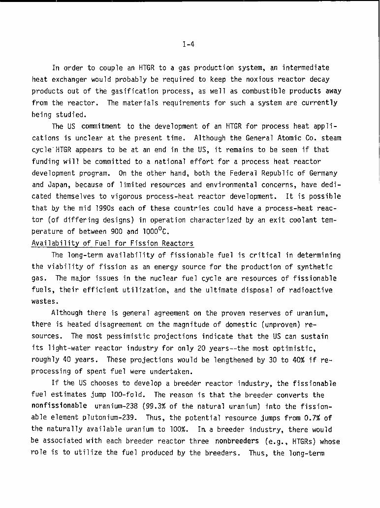
In order to couple an HTGR to a gas production system, an intermediate
heat exchanger would probably be required to keep the noxious reactor decay
products out of the gasification process, as well as combustible products away
from the reactor. The materials requirements for such a system are currently
being studied.
The US commitment to the development of an HTGR for process heat appli-
cations is unclear at the present time. Although the General Atomic Co. steam
cycle-HTGR appears to be at an end in the US, it remains to be seen if that
funding will be committed to a national effort for a process heat reactor
development program. On the other hand, both the Federal Republic of Germany
and Japan, because of limited resources and environmental concerns, have dedi-
cated themselves to vigorous process-heat reactor development. It is possible
that by the mid 1990s each of these countries could have a process-heat reac-
tor (of differing designs) in operation characterized by an exit coolant tem-
perature of between 900 and 1000°C.
Availability of Fuel for Fission Reactors
The long-term availability of fissionable fuel is critical in determining
the viability of fission as an energy source for the production of synthetic
gas. The major issues in the nuclear fuel cycle are resources of fissionable
fuels, their efficient utilization, and the ultimate disposal of radioactive
wastes.
Although there is general agreement on the proven reserves of uranium,
there is heated disagreement on the magnitude of domestic (unproven) re-
sources. The most pessimistic projections indicate that the US can sustain
its light-water reactor industry for only 20 years--the most optimistic,
roughly 40 years. These projections would be lengthened by 30 to 40% if re-
processing of spent fuel were undertaken.
If the US chooses to develop a breeder reactor industry, the fissionable
fuel estimates jump 100-fold. The reason is that the breeder converts the
nonfissionable uranium-238 (99.3% of the natural uranium) into the fission-
able element plutonium-239. Thus, the potential resource jumps from 0.7% of
the naturally available uranium to 100%. In,a breeder industry, there would
be associated with each breeder reactor three nonbreeders (e.g., HTGRs) whose
role is to utilize the fuel produced by the breeders. Thus, the long-term
ava
us,
1-5
lability of nuclear fission fuel is large if the breeder is used in the
small if it is not.
There is a good deal of controversy about disposal of radioactive
wastes. There is little disagreement among informed sources that adequate
isolation in underground depositories is possible, but there is substantial
disagreement about the particulars of such disposal.
FUSION
Nuclear fusion is the energy source of the stars. Light atomic nuclei
(e.g., hydrogen, helium) collide, forming a heavier nucleus and releasing
energy. The harnessing of nuclear fusion by mankind combines a great energy
resource potential with immense technological difficulties: the deuterium
(heavy hydrogen) present in one gallon of natural water could release, by
fusion, the energy equivalent of 300 gallons of gasoline; however, in order to
start the fusion process, the fuel gases must be heated to 50 million ‘C and
held together long enough for the fusion reactions to proceed completely.
The National Fusion Energy Program had its beginnings 25 years ago, and
has expanded to an operating budget of $400 million per year in the Department
of Energy. One approach called inertial confinement fusion (which includes
laser fusion) passed through a phase of unbridled optimism in the early 1970s,
with respected figures predicting the commercialization of laser fusion as an
energy source within ten to fifteen years. However, as the program matured
and a base of experimental data was taken, it became clear that there was no
straightforward scientific path leading to the commercial application of laser
fusion. DOE has recently estimated that the earliest operation of a fusion
demonstration plant would occur in the first decade of the 21st century, with
the first commercial fusion electric power plant in operation by 2015 or 2020.
Based upon the present thrust of the DOE fusion programs, the design of
synthetic fuel production as an integral part of a fusion reactor system would
be a second-generation fusion technology, and therefore be available much
later than fusion-based electric power plants. For these reasons, we recom-
mended and Texas Gas agreed that synthetic gas production from fusion energy
not be studied further in the context of the present contract. In looking to
the future, however, a status report on the fusion program and its long-range
1-6
plans was prepared, in order that
fifteen years, in order to determ”
pace with its projections.
SYNTHETIC GAS PRODUCTION PROCESSES
Coal Gasification
The potential application of nut”
was considered by a detailed original
Texas Gas might re-examine fusion in ten to
ne whether the National program has kept
ear heat sources to coal gasification
design of a catalytic coal gasification
process, analogous to Exxon’s catalytic gasification process for the produc-
tion of high-BTU gas. The Hygas process was considered, but because it uses
char to provide the necessary process heat, there is no demand for heat inputs
from a nuclear reactor.
A detailed chemical process analysis and a preliminary design were made,
based upon Exxon’s published catalytic data, in order to determine its heat
input requirements. Economic comparisons were made between the cost of pro-
viding these heat requirements from a High-Temperature Gas-Cooled Reactor
(HTGR) and from a conventional coal-fired plant.
Using the data from the preliminary design of a catalyzed coal gasifica-
tion plant given later in this report, it would appear that one 800 MW(th)
(65,500 x 106 BTU/d) HTGR could service about one standard-sized 250 x 106
SCFD coal gasification plant. The quantity of coal feedstock input for one
standard plant is about 10 to 12 thousand tons per day, and because of the
escalating costs and difficulties of coal transportation, the natural sites
for these plants would be at the mine-mouth, where nuclear energy would find
it most difficult to compete with coal burning. Other problems are the
coupling of two highly capital intensive plants, a gasification plant and an
HTGR, and the questions of reliability and availability of the latter.
In the preliminary design for catalytic coal gasification only about 15%
of the HTGR output is required for the high-temperature phase of the steam
gasification; about 45% goes to generating electricity for the power require-
ments of the system, and the remainder provides steam for the low-temperature
parts of the process. Thus there appears to be a good match between the divi-
sion of energy requirements of the gasification plant and the capability of
the nuclear reactor.
1-7
Because of the strong economics of scale in nuclear plants, an 800-MWt
nuclear plant would not be competitive with an 800-PIWt coal-fired plant. How-
ever, if the thermal requirement were provided from a 1500-MWt (461,000
x 106 BTU/d) nuclear plant, the cost of the heat input to the coal gasifica-
tion plant would be 20% less expensive than a conventional coal-fired plant,
and 5% below the cost of an atmospheric fluidized-bed coal plant. Therefore,
cogeneration of electricity and gas is a natural consideration, taking advan-
tage of both the economies of scale of nuclear plants, as well as using eco-
nomically the medium-temperature heat (of the helium after it has passed
through the gasifiers) for electricity generation.
The suitability of a nuclear plant to provide process heat for a US coal
gasification plant does not appear promising in the near term, largely because
of economics. More severe environmental standards (C02 concerns) or re-
strictions on the burning of fossil fuels for boilers could put nuclear power
back more strongly into the picture. In Germany and Japan, however, the en-
vironmental problems of coal burning and the economics
process heat a more attractive alternative.
Thermochemical Cycles
Thermochemical cycles are chemical processes that
of coal make nuclear
take water as the input
and then, in several chemical steps, produce hydrogen and oxygen. The energy
required to decompose the water is provided in heat inputs to the chemical
process. This area was surveyed because of the potential for fission energy
to provide the heat requirements.
There are three thermochemical cycles receiving major attention, two in
the US (General Atomic and Westinghouse) and one in Europe (ISPRA). These
cycles are now operating at laboratory-scale production rates of 4 cubic feet
of hydrogen per hour. These experiments are so small that reliable estimates
of efficiency and cost are not yet available, although efficiencies of 35-45%
and hydrogen costs of $7-10 per million BTU are projected. Commercialization
of any of these cycles would require development of materials that are corro-
sion resistant
The other
electrolysis.
thermochemical
at high temperatures.
major technology contender for future hydrogen production is
At present, the differences in efficiency and cost between
cycles and electrolysis are small, particularly in view of the
uncertainties.
decision could
pursue.
1-8
With an increased level of National effort in these areas, a
be made in 10-15 years on which of the two technologies to
Several schemes for removal of heat from a fusion reactor chamber were
analyzed. It is estimated that process heat will be available at temperatures
in the range 1200 to 1700°C. At these temperatures, it may be possible to
design two-step thermochemical cycles (i.e., involving only two chemical reac-
tions) at considerable savings in capital cost and increased efficiency as
compared with the lower temperature thermochemical cycles applicable to nu-
clear fission.
High-Temperature Electrolysis
Electrolysis is a process in which electricity is passed through a cell
containing water or steam; hydrogen is produced at one end of the cell and
oxygen at the other end. The electrolysis of water at room temperature to
produce hydrogen is inefficient: generation of electricity from thermal energy
is only 33% efficient; the electrolysis cell is 60-80% efficient, yielding an
overall efficiency (thermal to hydrogen) of 20-26%. Development of more effi-
cient electrolysis cells could raise this figure to 31%.
Electrolysis of high-temperature steam in porous materials is attractive,
because at elevated temperatures part of the energy required to produce the
hydrogen comes from heat rather than from electricity, and so a larger part of
the thermal-to-electrical energy inefficiency is circumvented. For example,
at 930°C (achievable with HTGRs), 73% of the energy investment is electrical
and 27% is heat; at 1830°C (expected to be achievable with fusion), 55% is
electrical and 45% is from heat.
The advantages gained by using superheated steam from an HTGR as part of
the energy input to an electrolyzer are marginal at best. The small thermo-
dynamic gains at practical reactor outlet temperatures (around 1000°C) will
likely be offset by the higher cost electrolyzers capable of operating in se-
vere environments. Developmental problems for electrolyzers at these tempera-
tures are significant.
Radiolysis
Radiolysis is a process in which the products of
trons, gamma rays, nuclear fragments - directly break
nuclear reactions - neu-
molecules apart. For

i
1-9
example, water can be decomposed into hydrogen and oxygen; or carbon dioxide
can be decomposed into oxygen and carbon monoxide. Because of the inherently
low efficiency of radiolysis (only 5-10% of the fission energy release can be
utilized in radiolysis of water), any viable system would have to find an eco-
nomic use for 90% of the reactor output energy, probably for electricity gene-
ration. The plant would then be an electricity generator with hydrogen as a
very minor by-product. Systems optimized for maximizing radiolytic hydrogen
production such as an aqueous homogeneous reactor would require a substantial
developmental program. In all cases, severe safety problems related to hydro-
gen explosions might be encountered.
Production of CO from radiolysis of C02 appears to be more efficient
than radiolytic hydrogen production, but there are many developmental prob-
1ems. Key issues in this development, which would require Federal sponsor-
ship, would be how to provide int
fuel particles to use the fission
the corrosion of steel components
for the reactor. To produce pipe”
mate contact between C02 and the nuclear
product energy, fission product removal, and
by the C02 which also serves as a coolant
ine gas, the CO would have to be put through
a shift conversion process with steam to form hydrogen.
Fusion-driven radiolysis is somewhat more attractive than fission-driven
radiolysis because of engineering considerations and because radioactive con-
tamination of the radiolyzed product can be maintained at a lower level. How-
ever, systems studies of fusion reactors have shown that radiolysis is not
competitive with electrolysis. Further, even if a 30% C02 radiolysis effi-
ciency could be achieved, radiolysis is not even viable as a topping cycle in
electric power generation.
2-1
SURVEY OF FISSION ENERGY SOURCES FOR THE PRODUCTION OFSYNTHETIC GASEOUS FUELS
INTRODUCTION
Synthetic gaseous fuels can be produced with the aid of energy from nu-
clear fission sources in a variety of ways. Hydrogen can be produced from
by nuclear plants, and from
the heat from high-tempera-
from coal with the assis-
reactors that can be used
direct radiolytic dissociation of water in the cores of certain reactors, from
electrolysis of water using electricity generated
thermochemical cycles and coal gasification using
ture reactors. Synthetic methane can be produced
tance of high-temperature reactors. The types of
for such fuel production and the liabilities of such production methods in
terms of economics and time scales are surveyed and discussed in this section.
A. Current Status of the HigFrTemperature Gas-Cooled Reactor (HTGR)
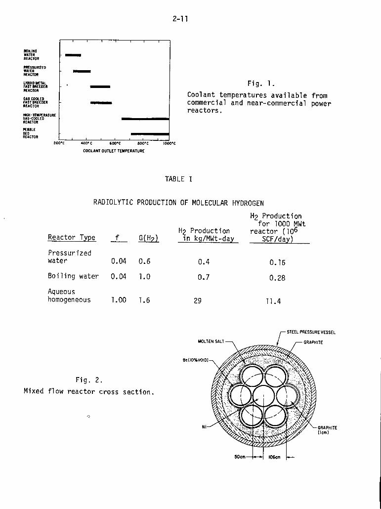
The application of nuclear reactor systems for the production of synthetic
gaseous fuels is limited by the temperature of the coolant at its exit from
the reactor core. Figure 1 illustrates the range of exit coolant temperatures
that occur with reactor systems that are currently being operated throughout
the world. Since the process temperatures for production of synthetic gaseous
fuels (e.g., coal gasification) discussed later in this report are in excess
of 800°C, it can be concluded from Fig. 1 that our attention must be focused
on the HTGR or very high-temperature reactor (VHTR) systems.
Germany, Japan, and the U.S. currently have active programs for develop-
ment of high-temperature (coolant temperature approximately 750°C) and very
high-temperature (coolant temperature in excess of 900°C) reactor systems.
Although the technology programs in the three countries have many similari-
ties, they also have strong dissimilarities either because of the reactor de-
sign or because of the process temperature requirement.
The U.S. has the only HTGR in operation at the present time, a steam cycle
prismatic core HTGR manufactured by General Atomic Company. The Fort St.
Vrain Nuclear Generating Station operated by Public Service Company of Colo-
rado for electricity production began a slow and protracted ascent to power at
the beginning of 1976. Numerous technical difficulties have been encountered
—

2-2
since then, most of which have involved the design of the helium circulators
and the seals between the steam turbine and the circulator. To compound the
difficulties, a core fluctuation phenomenon has been observed that was unex-
pected and is still not fully understood. The fluctuations involve changes in
the neutron detector channels, refueling region outlet thermocouple readings,
temperatures in the steam generator modules, and prestressed concrete reactor
vessel (PCRV) motion. Because of the unpredictable nature of the fluctuation
phenomena, the Fort St. Vrain plant has been limited to 70 percent of its
rated power of 330 MWe.
In probably what is a related development, the U.S. Department of Energy
in October, 1978, recommended to General Atomic Company and the Gas-Cooled
Reactor Associates (a consortium of utilities representing thermal gas reactor
development) that support of the HTGR steam cycle be discontinued and that
efforts be concentrated on advanced gas cooled reactor concepts. For example,
a direct cycle HTGR to be operational in 1992 was discussed. Also in the pic-
ture appear to be process heat nuclear reactors. In addition, cooperation
with the German effort was encouraged (see below). The relationship of the
events of the past year in the area of gas-cooled reactors is not clear, but
it now appears certain that the steam cycle HTGR will not be developed in the
U.S. in the forseeable future.l
In the Federal Republic of Germany during the past year there has also
been an effort to concentrate the gas-cooled reactor work.2 Two basic reac-
tor concepts, a direct cycle gas turbine for electricity production and a pro-
cess heat system are being studied. Both concepts employ the pebble-bed type
of reactor with a prestressed concrete reactor vessel. A 600 MWe demonstra-
tion plant is being proposed for electricity production. The system has an
outlet gas temperature of 950°C and an overall efficiency of 44.5 percent.
The plant could be on-line in 1992. A 500-kWt process heat plant is being
planned for somewhat later introduction. Much relevant German experience was
accrued during the operation for ten years of their AVR - a 50 MWt VHTR with
an exit coolant temperature of 950°C, which should allow them to confidently
design the larger reactor systems.

2-3
At the moment, the top priority in the German gas reactor program is the
completion of the 300 MWe thorium high-temperature reactor (THTR) plant lo-
cated at Schmehausen. Good progress has been reported and it is now hoped
that the plant will be completed in 1981.
Japan has mounted a vigorous program for development of a VHTR to be used
in steelmaking using nuclear process heat. The lack of a sufficient quantity
of fossil fuels and a severe environmental pollution problem caused by the
present steelmaking process have combined to push the development of a multi-
purpose HTGR which will supply the required heat for a direct-reduction steel-
making process. The work in reactor development is directed by the Japan
Atomic Energy Research Institute (JAERI) and is predicated on a reactor exit
helium temperature of 1000°C. Some in-pile subassembly tests dealing with
VHTR fuel irradiation, fission product transport, and component integrity are
already in progress in the OGL-1, a helium gas loop located at the Oarai Re-
search Establishment. In addition, material tests (on Hastalloy steels and
Inconel 617 steel) are ongoing in a prototypical intermediate stage heat ex-
changer that has been designed for a hot side temperature of 1000°C. The
large scale of the Japanese test loops and experiments indicate the degree of
commitment that Japan is giving to the development of a VHTR (spending on the
VHTR program is estimated at $100million/year). Finally, an experimental
prismatic core VHTR with a thermal output of 50 MWt and a coolant exit temper-
ature of 1000°C
built by 1986.3
In summary,
city production
will be used in
cess heat.
has been designed with plans to have the reactor system
The estimated cost is $500 million.
it appears that the use of HTGRs in a steam cycle for electri-
has lost the potential that it once had. In the future HTGRs
those applications that are unique to the HTGR, such as pro-
B. Radiolytic Production of Hydrogen
The chemical bonds that hold the water molecule together can be broken by
ionizing radiation. The principal ionizing radiations in a fission reactor
power plant are fission fragments, beta particles produced by fission product
decay, gamma rays produced directly by fissi,on and also by neutron capture and
fission product decay, and neutrons. The ast two ionize indirectly, gamma

2-4
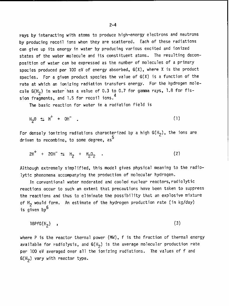
rays by interacting with atoms to produce high-energy electrons and neutrons
by producing recoil ions when they are scattered. Each of these radiations
can give up its energy in water by producing various excited and ionized
states of the water molecule and its constituent atoms. The resulting decom-
position of water can be expressed as the number of molecules of a primary
species produced per 100 eV of energy absorbed, G(X), where X is the product
species. For a given product species the value of G(X) is a function of the
rate at which an ionizing radiation transfers energy. For the hydrogen
cule G(H2) in water-has a value of 0.3 to 0.7 for gamma rays, 1.8 for f
sion fragments, and 1.5 for recoil ions.4
The basic reaction for water in a radiation field is
H20 s H+ + OH- . (1)
For densely ionizing radiations characterized by a high G(H2), the ions
driven to recombine, to some degree, as5
2H+ + 20H- c Ho + H90, . (2)L L(2
Although extremely simplified, this model gives physical meaning to
lytic phenomena accompanying the production of molecular hydrogen.
In conventional water moderated and cooled nuclear reactors,rad
mole-
s-
are
the radio-
olytic
reactions occur to such an extent that precautions have been taken to suppress
the reactions and thus to eliminate the possibility that an explosive mixture
of H2 would form. An estimate of the hydrogen production rate (in kg/day)
is given by6
18PfG(H2) , (3)
where P is the reactor thermal power (MW), f is the fraction of thermal energy
available for radiolysis, and G(H2) is the average molecular production rate
per 100 eV averaged over all the ionizing radiations. The values of f and
G(H2) vary with reactor type.

2-5
In an aqueous homogeneous reactor where the fissile material is in solu-
tion with the aqueous moderator-coolant, f is close to unity and G(H2) is
approximately 1.6. Ninety-six percent of the H2 is produced by fission
fragments and the remaining four percent is produced by neutrons, gamma rays,
and beta particles. For conventional light water reactors, fission fragments
and beta particles are isolated from the water by the nuclear fuel cladding
and radiolysis occurs only by fast neutrons and gamma rays. This limits the
value of f to about 0.04 (the fraction contributed by neutrons and gamma rays)
and limits the value of G(H2) to approximately 0.6 for boiling water reac-
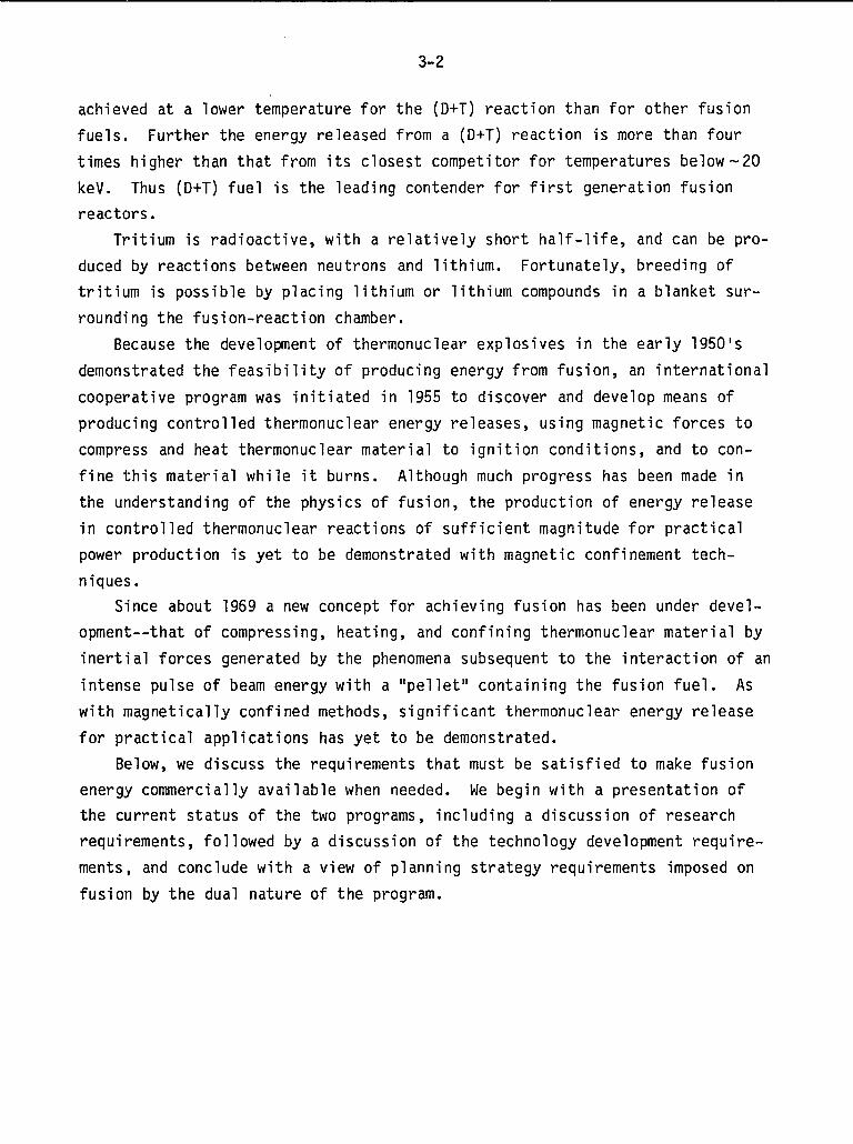
tors and 1.0 for pressurized water reactors.6 The potential production of
molecular hydrogen from these three reactor types is summarized in Table I.
We can calculate the energy efficiency for hydrogen produced by radioly-
sis. Using a heating value of hydrogen of 325 BTU/SCF, a straightforward cal-
culation gives an efficiency of about 5 percent for the optimal case of an
aqueous homogeneous reactor. This implies that a reactor system designed
solely for the radiolytic production of hydrogen is not feasible, and that
even in the optimal system, hydrogen generation by radiolysis must be ancil-
lary to the production of electricity.
Molecular decomposition of carbon
other possible means of production of
cal reaction is
C02+C0 + 1/202 ,
dioxide by ionizing radiations is an-
hydrogen. In this case the basic chemi-
(4)
whereupon the water-gas shift reaction
CO + H20 ~H2 + C02 (5)
can be used for production of the hydrogen. Since C02 has been used as the
coolant in the British and French gas-cooled reactors (the MAGNOX and AGR
reactors), it might prove economical to optimize these reactors for CO produc-
tion.
There is a considerable amount of experimental data on the radiolysis of
C02 including radiations with and without fission fragments, for which a
2-6
G(CO) equal to 10 and a resulting high conversion efficiency (- 30 percent) is
claimed. For radiolysis with radiations other than fission fragments, a value
of G(CO) equal to about 4 is achievable, which corresponds to a conversion
efficiency of about 12 percent. Furthermore improved efficiencies for radio-
lysis of C02 have been observed at elevated temperatures or by the use of
additives and scavengers. Conversion efficiencies of 30 percent deserve fur-
ther consideration as a means of hydrogen production although even here elec-
tricity production would be the major product.
In a fission nuclear system designed to radio”
also be used as a coolant to remove the heat from
Safety considerations would probably require that
yze C02, the C02 would
the core of the reactor.
the fission product frag-
ments be retained within a cladding of nuclear fuel. This, however, prevents
attainment of the higher radiolysis efficiencies associated with fission frag-
ments. Thus, the practicalities of developing and licensing a C02 gas reac-
tor would preclude optimization toward radiolytic production of CO.
In conclusion, the low efficiency inherent in the production of hydrogen
by radiolysis coupled with the technological problems associated with the
handling of hydrogen and those of corrosion enhanced by the presence of hydro-
gen or carbon dioxide would seem to preclude radiolysis as a viable means of
hydrogen production.
c. Gas Core Reactors for High-Temperature Process Heat
General - It has been suggested recently that gaseous core reactors have
several attractive applications in meeting future energy needs.7 Uranium
fuel in gaseous or plasma form permits operation at much higher temperatures
than possible with conventional solid fueled nuclear reactors. Higher working
fluid temperatures in general imply higher thermodynamic cycle efficiencies
for advanced closed-cycle gas turbine driven electricity generators and mag-
neto-hydrodynamic (MHD) power conversion systems for electricity production.
Of course, higher working fluid temperatures, also allow high process heat
temperatures, which make many photochemical and thermochemical processes at-
tractive, such as hydrogen production by dissociation of hydrogeneous
materials.
The Los Alamos Scientific Laboratory has recently completed a study
gaseous core power plants designed for low proliferation potential.8
of I
2-7
Characteristics of gaseous core power plants,
feature, are described in Sec. 1 below. Sec.
excluding the low proliferation
2 and Sec. 3 briefly describe
the two proposed core concepts, the mixed flow and plasma core designs,
respectively, and Sec. 4 summarizes the drawbacks of these reactors as far as
production of synthetic gaseous fuels. Section 5 discusses the photochemical
production of synthetic gaseous fuels using a plasma core reactor.
1. General Characteristics of Gaseous Core Power Plants. Because the
fuel is a gas there is no need to manufacture fuel elements and, therefore, no
need to process them. Nor is there a need to shut down the reactor to replace
fuel elements because fuel can be introduced continuously while the reactor is
operating. The fission products are generated in and carried by the gas,
offering the possibility of removing them as the gases circulate in the loop.
If the reactor is designed as a sustainer, converting thorium to 233U
with a breeding ratio of one - and if a fluid breeding blanket such as the one
developed by the Oak Ridge National Laboratory in the Molten Salt Breeder
Reactor (MSBR) is used - the newly born 233U can be continuously processed
and fed back into the reactor to maintain continuous operation. This allows
one-time movement of fissile material. Only the initial charge of uranium
would have to be brought into the plant and no additional shipments would be
required. In addition, this continuous feed of newly formed fuel makes it
unnecessary to keep excess fissile material in the structure to sustain opera-
tions for a period of time.
Heat transfer rates are high. Heat conduction is not utilized in the
reactor. Energy is transferred either by convecting the gaseous fuel itself
or by thermal radiation from the fuel plasma.
2. Mixed Flow Reactor. In the mixed flow reactor, UF6 and helium gas
are intimately mixed and injected into a cylindrical cavity. By establishing
a vortex flow in the cavity, a cooler outside gas flow and a hotter interior
gas flow can be established, which accomplishes the goals of withdrawing a
high-temperature process gas from the interior flow and protecting the cavity
wall by the outer bypass flow.
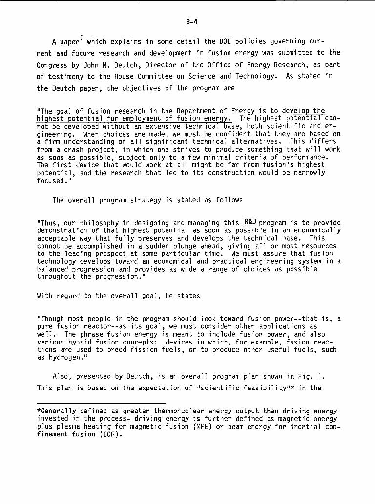
Figure 2 illustrates a cross section of the mixed flow reactor showing
seven cavities, each of which is surrounded b~ a beryllium moderator, the salt
2-8
breeder blanket, a graphite reflector, and a pressure vessel capable of
holding the 100 atmosphere internal pressure. The system shown produces 200
MWt, with a 1225 K mixture of UF6 and helium, and has been neutronically
designed for an inventory of about 100 kg of fissile material.8 The
UF6-helium mixture is passed through a heat exchanger and the heat is dumped
to a secondary helium loop (with a 50-100 K temperature loss) that can either
be used to drive a gas turbine or can be used in process heat applications.
3. Plasma Core Power Plants. The impetus for developing plasma core
reactors is their higher operating temperatures (above 4700°C),thus making
attractive applications in advanced closed cycle, gas-turbine-driven electri-
city generators and in photochemical”or thermochemical processes for the pro-
duction of hydrogen. Because, in plasma reactors, the fuel gas (gaseous
uranium rather than UF6) reaches temperatures exceeding 4700°C, an argon
buffer gas is circulated in a confining vortex to keep the gaseous uranium
from the walls. Essentially the same cavity design is used in the plasma core
design as is used in the mixed flow reactor except that the argon and uranium
gases are not premixed. Breeder blanket, graphite reflector, and pressure
vessel are much the same as in the mixed flow reactor.
Neutronic designs of two plasma core reactors have been presented in
Ref. 5.
4. Problems with Gaseous Core Nuclear Plants. Gaseous core fission reac-
tors possess the necessary high-temperature capability for process heat appli-
cations and also
self-sustaining in
fissile material.
in the development
embody many desirable features in a nuclear heat source:
fuel, continuous operation, low potential for diversion of
However, numerous technological problems must be overcome
of such a heat source, particularly for the hicjh-tempera-
ture plasma core reactor. Some of the technological areas that must be
studied include
a. Fluid mechanics and thermodynamics (both reactors) together with buf-
fer confinement (plasma core reactor).
b. High-temperature fluorine corrosion (mixed flow reactor) and high-
temperature uranium chemistry (plasma core reactor).
c. Processes for removing fission products and fission product transport
in the fuel loops for both reactor systems.

2-9
d. Optical properties of materials (plasma core reactor).
e. Reactor dynamics (both reactors).
A study program leading to the development of gaseous core reactors has
recently been curtailed by its sponsor, the National Aeronautics and Space
Administration. The reason given was lack of support by other government
agencies, such as the Department of Energy. Until adequate funding is sup-
ported by the Federal government, the solution of the technological problems
listed above will be postponed into the future. Once these problems have been
solved, gas core reactors might then be engineered for various applications in
the production of synthetic gaseous fuels. At best, it appears that 30 to 50
years would be required if a vigorous program were instituted now.
5. Photochemical Production of Synthetic Fuels
Dissociation of water into hydrogen and oxygen, or carbon dioxide into
carbon monoxide and oxygen, can be accomplished by photochemical means in
which photons of sufficient energy can break the chemical bonds. Since the
energy from a plasma core reactor operating at 4700°C would be transferred
largely by radiation, the feasibility of using this reactor concept as a
photochemical synthetic fuel plant has been investigated.
To photochemically dissociate water or carbon dioxide requires photon
energies of at least 5.0 eV and 7.5 eV, respectively. The energies of the
photons emitted from the core plasma will not all be at the same energy, but
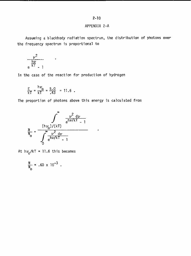
will have an energy distribution given by the blackbody radiation law (see
Appendix 2-A). At 5000 K, the average photon energy is only 0.43 eV and the
proportion of the photons having energies of 5.0 eV or larger (the dissocia-
tion threshold for water) is onlyO.6 x 10-3. Thus, in a 3000 MWt (246,000
x 106 BTU/d) plasma core reactor, which emits a total of 4.4 x 1028
photons/s, only 2.6 x 1025 would be above the water dissociation threshold.
If all of these photons split water molecules, the daily hydrogen production
would amount to 15000 lbs/d. In terms of BTU output, it would take over 250
such reactors to match one standard high-BTU coal gasification plant which
produces 250 x 106 CFD of methane. The situation would be worse for C09
dissociation because of the higher threshold energy (7.5
eV for water).
We conclude from the above analysis that the product
from plasma core reactors via photochemical splitting of
dioxide is not commercially viable.
eV compared wi~h 5.0
on of synthetic fuels
water or carbon

the
2-1o
APPENDIX 2-A
Assuming a blackbody radiation spectrum, the distribution of photons over
frequency spectrum is proportional to
J
elf,.
In the case of the reaction for production of hydrogen
The proportion of photons above this energy is calculated from
a
f
V2 dvenv/kT - ,
N—=No
(hvo)/(kT)00
f
V2 dvehv/kT - ,
0
At hvo/kT = 11.6 this becomes
.
N -3~=”60x’o “
2-11
::;;;0
REACTOR
PWESSURIZELlWATERREACTOR
Ll~10 METALFASTBREEOERREACTOR
6As COOLEOFAST8REEOERREACTOR
H161t-TEMPERATuREGAS-COOLEORE4CTOR
PE8BLEBEOREACTOR
2(
, , I , 1 T 1
I
I. I Fig. 1.
Coolant temperatures available fromcommercial and near-commercial powerreactors.
~‘c 1000”c
COOLANT OUTLET TEMPERATuRE
RADIOLYTIC
Reactor Type
Pressurizedwater
Boiling water
Aqueoushomogeneous
f
0.04
0.04
1.00
TABLE 1
PRODUCTION OF MOLECULAR HYDROGEN
H2 Productionm in kg/MWt-day
0.6 0.4
1.0 0.7
Fig. 2.
Mixed flow reactor cross section.
‘2
MOLTEN SALT -
1.6 29
H2 Productionfor 1000 MWt
reactor (106SCF/day)
0.16
0.28
11.4
-r STEEL PRESSURE VESSEL
. ~ GRAPHITE
t.mi%iwkfw’%%””E
50cm++ 106cm ~
2-12
REFERENCES
10
2.
3.
4.
5.
6.
7.
8.
R. D. Schamberger, “Overview of the USNRC Safety Reseach Programon High Temperature Gas-Cooled Reactors,” Invited address to the2nd Joint US/Japan Seminar on Gas Reactor Safety, Tokyo, Japan .(Nov. 22, 1978).
“HTR Program Reorientation,” Nuclear News 21(7), 68 (May 1978).—
“Research and Development of Multi-Purpose VHTR,” Japan AtomicEnergy Research Institute (1978).
J. A. Lane, H. G. McPherson, and F. Maslan, Fluid Fuel Reactors(Addison-Wesley Publishing Co., Reading, MA, 1958).
G. K. Whitham and R. R. Smith, “Water Chemistry in a Boiling WaterReactor,” Proc. 2nd Geneva Cong., I, 436 (1958).
W. Kerr and D. P. Majumdar, “Aqueous Homogeneous Reactor forHydrogen Production,” in Hydrogen Energy Part A (Plenum Press, NewYork, 1975), 167-181.
T. S. Latham, F. R. Biancardi, and R. J. Rodgers, “Applications ofPlasma Core Reactors to Terrestrial Energy Systems,” AIAA paper74-1074, AIAA/SAE 10th Propulsion Conf., San Diego, CA (October21-23, 1974).
L. Lowry, “Gas Core Reactor Power Plants Designed for Low Proli-feration Potential,” Los Alamos Scientific Laboratory report LA-6900-MS (September 1977).
3-1
DEVELOPMENT OF FUSION ENERGY - PRESENT AND FUTURE
INTRODUCTION
Thermonuclear fusion requires a process for supplying energy to fusion-
fuel ions, such that the ions have sufficient kinetic energy to overcome elec-
tric repulsive forces, in order to fuse in exothermic reactions. Because the
cross section for scattering is much greater than that for fusion reactions,
this can only be done exoergically in a thermal plasma, thus fusion fuel must
be heated to very high temperatures to initiate fusion reactions.
There are three principal fusion fuels based on the following reactions
D+D~3He+n+3.27MeV
I
(50% probability for either reaction)
D+D~T+H+4.03MeV
D +T 44He +n + 17.6 MeV
T +T~4He + 2n + 11.33 MeV
D + 3He-4He + H + 18.3 MeV.
Deuterium is found in nature, the major source being heavy water (HDO)
with a concentration of 0.015% in natural water, making this fuel source vir-
tually inexhaustible. Tritium and helium-3 are produced by nuclear processes,
including possible (D+D) fusion, but they do not occur naturally in signifi-
cant quantities. From the aspect of resource availability, deuterium is the
logical fuel choice. However, conditions required to achieve thermonuclear
ignition are the primary consideration at this time, and these are related to
the Maxwellian velocity-averaged reaction cross section ~v. The (D+T) reac-
tion is about 100 times more probable than the (D+D) reaction in the tempera-
ture range 10-100 keV (1 eV = 11600 K), and a given value ofa—v can be

3-2
achieved at a lower temperature for the (D+T) reaction than for other fusion
fuels. Further the energy released from a (D+T) reaction is more than four
times higher than that from its closest competitor for temperatures below-20
keV. Thus (D+T) fuel is the leading contender for first generation fusion
reactors.
Tritium is radioactive, with a relatively short half-life, and can be pro-
duced by reactions between neutrons and lithium. Fortunately, breeding of
tritium is possible by placing lithium or lithium compounds in a blanket sur-
rounding the fusion-reaction chamber.
Because the development of thermonuclear explosives in the early 1950’s
demonstrated the feasibility of producing energy from fusion, an international
cooperative program was initiated in 1955 to discover and develop means of
producing controlled thermonuclear energy releases, using magnetic forces to
compress and heat thermonuclear material to ignition conditions, and to con-
fine this material while it burns. Although much progress has been made in
the understanding of the physics of fusion, the production of energy release
in controlled thermonuclear reactions of sufficient magnitude for practical
power production is yet to be demonstrated with magnetic confinement tech-
niques.
Since about 1969 a new concept for achieving fusion has been under devel-
opment--that of compressing, heating, and confining thermonuclear material by
inertial forces generated by the phenomena subsequent to the interaction of an
intense pulse of beam energy with a “pellet” containing the fusion fuel. As
with magnetically confined methods, significant thermonuclear energy release
for practical applications has yet to be demonstrated.
Below, we discuss the requirements that must be satisfied to make fusion
energy commercially available when needed. We begin with a presentation of
the current status of the two programs, including a discussion of research
requirements, followed by a discussion of the technology development require-
ments, and conclude with a view of planning strategy requirements imposed on
fusion by the dual nature of the program.

3-3
CURRENT PROGRAM
General
The largest
of Energy (DOE)
STATUS
fusion program in the world is supported by the US Department
at a level of $481 million in FY’79 for both magnetic and
inertial confinement. This support has been supplemented by the Electric
Power Research Institute (EPRI) at a level of 3 to 4 million dollars per year
for system and applications studies. The second largest program is in the
USSR at a level about two-thirds that of the US program. Information exchange
between the US and USSR magnetic fusion programs is accomplished by a formal
exchange agreement (no such agreement exists for inertial fusion information
exchange). Smaller fusion programs are supported in Japan, the United King-
dom, and by the Organization for European Economic Development.
Because of the large cost of the US program, and because a first prototype
reactor is not expected until after the end of this century, the DOE initiated
a review process in early 1978. The six-month long review was directed by the
Fusion Review Committee, comprising the DOE Assistant Secretary for Energy
Technology, the Assistant Secretary for Defense Programs, and, as Chairman,
the Director of Energy Research. The committee and an attendant working group
scrutinized the program’s objectives, strategies, and status; assessed the im-
pacts of alternative budget scenarios, including some involving both small and
large funding reductions; and examined the large experimental projects in cost
and risk analysis. Also, an Ad Hoc Experts Group of distinguished scientists
from outside the fusion community, which was chaired by John W. Foster of TRW,
evaluated the status and prospects of the entire program.
From all of this examination and deliberation an extraordinarily high
degree of consensus emerged. The most important conclusions were that the
program is technically sound and that it holds excellent promise of ultimately
achieving the goal of commercial fusion energy. Other important conclusions
were: the United States now has world leadership in fusion energy research
and development, and this lead should be maintained; the current level of
funding was determined to be appropriate (decreases would, in fact, delay the
date of commercial availability of fusion); and the general strategy for the
solution of scientific and technological problems was upheld, with recommenda-
tions for some broadening and shifting of emphasis.
3-4
A paperl which explains in some detail the DOE policies governing cur-
rent and future research and development in fusion energy was submitted to the
Congress by John M. Deutch, Director of the Office of Energy Research, as part
of testimony to the House Committee on Science and Technology. As stated in
the Deutch paper, the objectives of the program are
“The goal of fusion research in the Department of Energy is to develop the%ighest potential for employment of fusion energy. The highest potential can-not be develo~ed without an extensive technical base, both scientific and en-gineering. When choices are made, we must be confident that they are based ona firm understanding of all significant technical alternatives. This differsfrom a crash project, in which one strives to produce something that will workas soon as possible, subject only to a few minimal criteria of performance.The first device that would work at all might be far from fusion’s highestpotential, and the research that led to its construction would be narrowlyfocused.”
The overall program strategy is stated as follows
“Thus, our philosophy in designing and managing this R&D program is to providedemonstration of that highest potential as soon as possible in an economicallyacceptable way that fully preserves and develops the technical base. Thiscannot be accomplished in a sudden plunge ahead, giving all or most resourcesto the leading prospect at some particular time. We must assure that fusiontechnology develops toward an economical and practical engineering system in abalanced progression and provides as wide a range of choices as possiblethroughout the progression.”
With regard to the overall goal, he states
“Though most people in the program should look toward fusion power--that is, apure fusion reactor-- as its goal, we must consider other applications aswell. The phrase fusion energy is meant to include fusion power, and alsovarious hybrid fusion concepts: devices in which, for example, fusion reac-tions are used to breed fission fuels, or to produce other useful fuels, suchas hydrogen.”
Also, presented by Deutch, is an overall program plan shown in Fig. 1.
This plan is based on the expectation of “scientific feasibility”* in the
*Generally defined as greater thermonuclear energy output than driving energyinvested in the process --driving energy is further defined as magnetic energyplus plasma heating for magnetic fusion (MFE) or beam energy for inertial con-finement fusion (ICF).

3-5
early-80’s for MFE and in the mid-80’s for ICF. Upon achievement of scienti-
fic feasibility, a driver selection for MFE and ICF will be made for further
R&D in Engineering Test Facilities (ETF). These facilities will be integrated
systems producing net energy gain using fusion plasma techniques developed in
the previous generation of experimental devices. The Engineering Test Facili-
ties will also establish the technological requirements of each of the major
components of a prototype reactor.
The next phase of the program, demonstration, will involve the operation
of an Engineering Prototype Reactor (EPR), which first combines the elements
tested in the superior Engineering Test Facility into a pilot plant in which
the unknowns of reactor design can be tested and resolved. The EPR will ap-
proach, for the first time, complete energy gain, where the energy produced
exceeds all energy consumed in keeping the entire plant running. Finally,
demonstration will be completed with the construction of one or more commer-
cial demonstration reactors, in which net power gain in excess of 100 MW per
plant is produced with an economic efficiency that will make them attractive
to industrial investors. Full commercialization of fusion energy will have
been accomplished when about one tenth of a quad per year, which is about the
equivalent of three 1,000 MW power plants, is produced.
Magnetic Fusion Program
The US magnetic fusion energy program is managed by the DOE Office of
Fusion Energy and is organized into four interrelated subprograms: confine-
ment systems, development and technology, applied plasma physics, and techni-
cal projects. The last of these is an office which supervises the construc-
tion of major facilities such as the Tokamak Test Fusion Reactor (TFTR).
The magnetic fusion program is carried out at five major sites: General
Atomic Company, Lawrence Livermore Laboratory, Los Alamos Scientific Labora-
tory, Oak Ridge National Laboratory, and Princeton Plasma Physics Laboratory.
Many smaller programs are also in progress at other laboratories, industries,
and universities.
Confinement Systems
The confinement systems program is responsible for solving the experi-
mental problems connected with the confinement of fusion plasma by magnetic
3-6
fields; to demonstrate long-time confinement of high-temperature plasmas at
power-producing reactor conditions and to optimize the plasma physics aspects
of fusion reactor systems. The most important parameter for a fusion reactor
is the plasma temperature and the so-called Lawson parameter, n’r,where n is
the number density of particles and T is the confinement time. For a fusion
reactor, the plasma temperature needs to be - 10 keV for both ions and elec-15trons, and nT must be of the order of 10 s/cm3.
The principal approach to the confinement of plasma is the tokamak which
is a donut-shaped, long pulse time, moderate-density device. In addition, a
strong effort is maintained in magnetic mirror systems, including both open
and toroidally linked mirror systems. Smaller efforts are maintained in high-
density short-pulsed systems, including the linear theta pinch, the toroidal
Z-pinch, and imploding liner concepts.
Tokamaks - The major problem areas of the tokamak physics program are
heating, transport and scaling, plasma shape-optimization, impurity control
and boundary effects, and fueling.
Heating refers to the process of producing the plasma temperatures neces-
sary for a fusion reactor. Methods of heating include ohmic heating by in-
ducing plasma currents with magnetic fields, induction heating by microwaves,
and heating by injection of high-energy neutral particles.
Transport and scaling refers to the develo~ent of the physical laws which
describe the measured transport of plasma energy in present experiments and
the development of scaling laws to predict plasma behavior in larger, higher
temperature devices. This area is, therefore, closely related to the heating
program, and research on the two is conducted simultaneously.
This research has been carried simultaneously using the Alcator at the
Massachusetts Institute of Technology, the ORMAK at Oak Ridge, T-10 in Moscow,
and the PLT at Princeton. The experiments have been directed at understanding
of the scaling of the nT parameter, sometimes called the quality of confine-
ment. This scaling in tokamaks depends fundamentally on four parameters:
density, size, temperature, and magnetic field strength.
In early 1978, Alcator experiments indicated the unexpectedly favorable
result that nT increases as density squared over a range of several factors of
ten and even beyond that required for a reactor.

3-7
With regard to size scaling, experiments without auxiliary
using the ORMAK, T-10, and PLT devices indicate n’fto scale as
plasma heating
the square of
the torus size, an expected result. Furthermore, these experiments have re-
vealed no explicit dependence on magnetic field strength.
Recent experiments on PLT have indicated the dependence of nr on tempera-
ture, the remaining parameter of concern. The most significant result from
these experiments is that nr does not decrease significantly at a temperature
of - 6 keV, near that needed for a fusion reactor. This unexpected result is
very favorable because it was previously believed that nr would decrease mark-
edly at this temperature due to plasma instabilities. This result has created
confidence that the goal of “scientific feasibility” will be met with experi-
ments on the TFTR.
Plasma shape optimization addresses the possibility, predicted by theory,
that non-circular plasma shapes can be confined by lower strength magnetic
fields and thus lead to lower fusion power plant costs.
Impurity control and boundary effects refers to problems resulting from
the interaction of the plasma with its material boundaries. These interac-
tions can result in an influx of non-hydrogenic (impurity) atoms into the
plasma, which can cool the plasma core directly and/or can cool the plasma
edge, causing the plasma to shrink and become unstable.
Mirrors - The mirror program consists of investigation of two configura-
tions for ultimate steady-state operation: open systems, and toroidally
linked mirrors. Experiments on open systems, currently considered the runner-
UP to tokamaks (conducted at Livermore), with the 2X-IIB “baseball” magnetic
field configuration, have successfully demonstrated plasma scaling parameters,
i.e., nT- T3’2 at ion energies up to 13 keV and at an ion gyroradius,9
R/ i, in the range of 2-3. Reactor conditions will require ion energies of
> 50 keV and R/pi > 40. Experiments are planned for the MX device (opera-—tional in the early ‘80s) at ion energies of - 50 kev and R/Pi of - 13.
Success with MX experiments will lead to tandem mirror experiments (TMX), in
which a linear system of mirror configurations will be built using baseball
coils to minimize end loss. This latter configuration would provide high
enough energy gain for the open mirror concept. to be economically viable.
3-8
The toroidally linked mirror concept, called the Elmo Bumpy Torus (EBT),
is being studied at Oak Ridge. The major problem areas for EBT are plasma
stability and microwave heating. Plasma stability has been demonstrated at
densities up to - 6 x 10¹²/cm3 at a microwave frequency of 28 GHz. How-
ever, microwave heating at -100 GHz and at densities of - 1014/cm3 needs
to be demonstrated for reactor conditions.
High-density systems - Experiments on these systems are conducted at Los
Alamos. These systems include the linear theta pinch, z-pinch, and imploding
liner concepts. Work has been abandoned on the toroidal theta pinch because
of demonstrated plasma instabilities.
Linear theta pinch experiments are being conducted on the SCYLLA IV
device. The major problems are end loss and high field operation. Without
some form of end-stoppering, a fusion reactor based on this concept would be
impractically long (many kilometers). A variety of methods are under investi-
gateon. High field operation is essential because reactor length varies as
the inverse of the magnetic field strength squared, therefore the reactor
length decreases dramatically at higher magnetic fields.
Z-pinch experiments on the ZT-1 device have indicated plasma stability and
the potential for reaching ignition conditions by joule and shock heating.
Experiments planned for the ZT-40 device will determine the validity of this
potential.
The imploding liner concept offers the highest potential of achieving ig-
nition without plasma instabilities among the various pulsed magnetically
driven systems. Experiments are underway to establish the feasibility of this
concept.
Development and Technology
The development and technology program provides both near-term engin-
eering/subsystems support to existing and proposed experiments and longer term
development of the necessary technology base to permit fusion energy to become
a commercial reality. Development and technology program activities presently
are organized in five related subprograms: magnetic systems, plasma engineer-
ing, reactor materials, systems engineering, and environment and safety.
Magnetic systems sponsors research and development of large supercon-
ducting magnet systems needed for fusion reactor engineering experiments with-

3-9
in the next ten years. Plasma engineering is directed principally at the
development of efficient plasma heating systems (neutral particle beams,
radio-frequency waves, and electromagnetic plasma implosion systems) that are
essential for the various confinement concepts.
The reactor materials activity is assigned the responsibility to develop
(or invent) the materials required to permit the economical generation of
energy from the fusion process. The principal focus is on materials that will
be placed within the first ten centimeters or so of the plasma where the
fusion radiation environment imposes the most difficult materials requirements.
Systems engineering focuses principally on the next generation and longer
term fusion power reactor designs. Specifically, a major responsibility is to
support the reactor designs necessary for Congressional approval (and funding)
to build the first large fusion prototype experimental power reactor.
Environment and safety is charged with the responsibility of assuring that
fusion power reactors will operate with the minimum possible hazard either to
the environment or to plant personnel and nearby populations.
Applied Plasma Physics
The applied plasma physics program seeks the body of knowledge that pre-
dicts the behavior of fusion plasma confinement experiments and the operating
characteristics of fusion power reactors. The program is composed of theore-
tical activities, including its computational components, and experimental
plasma research, which supports a broad spectrum of experiments to attack
problems related to the production and confinement properties of fusion plasma.
Tokamak Fusion Test Reactor
The Tokamak Fusion Test Reactor (TFTR) will be the first magnetic confine-
ment fusion device to experimentally demonstrate the release of fusion energy
from the deuterium-tritium reaction under conditions projected for future ex-
perimental power reactors. TFTR will represent an intermediate step between
present, relatively small zero-power physics experiments and future experi-
mental reactors. The TFTR will be located at the Princeton Plasma Physics
Laboratory (PPPL). The project should be completed in mid-1981 at a total
cost of $228 million.
The TFTR has major objectives in both physics and engineering. The prin-
cipal objectives are
3-1o
0 To demonstrate fusion energy production from the burning of deuterium and
tritium (DT) in a magnetically confined toroidal plasma system.
o To build a neutral beam heated tokamak in which hydrogen, deuterium) and DT
plasma can be inserted in order to
study the physics of large tokamaks, and
verify advanced engineering concepts for DT tokamak systems.
● To experimentally demonstrate physics and engineering understanding of
large fusion systems.
The unique features of the TFTR are its DT burning capability, its size
which permits physics experiments in the reactor range of interest, and some
of its engineering features, not heretofore tested. The experience to be
gained in design, construction) and operation, and the information to be
gathered in physics and engineering will provide a sound foundation for poten-
tial larger systems.
●
●
●
●
●
●
The specific objectives of the TFTR project are
Attain reasonably pure plasma conditions at 5-10 keV temperature, approxi-14 -3mately 10 cm density, and provide stable confinement with n equal
to or greater than 1013 s/cm3.
Provide a neutral beam injection system capable of injecting into the
plasma 20 MW of a 120-keV neutral deuterium beam, for at least 0.5 s.
Provide a toroidal magnetic field of about 5 tesla (50 kG) (on vacuum
chamber axis), for at least 3 s flattop time, with a 5 minute repetition
rate.
Develop plasma handling techniques and provide hardware capable of initia-
tion, control (including feedback control and major radius compression),
and dissipation of tokamak discharges up to 2.5 MA.
Provide a vacuum chamber of adequate size (2.7-m major radius and l.1-m
minor radius), equipped for high-power discharge cleaning and capable of
achieving base pressures below 5 x 10⁻⁸ torr.
Provide capability for routine pulsed operation with H-H; D-D; D-He3; or
DT plasmas, with safe and reliable gas handling and support systems.

3-11
Inertial Confinement Fusion Program
The US inertial confinement fusion program is managed by the DOE Office of
Laser Fusion and is conducted principally at the Lawrence Livermore Laboratory
(LLL), the Los Alamos Scientific Laboratory (LASL), and the Sandia Labora-
tories at Albuquerque (SLA). Smaller research programs are conducted at KMS
Fusion, Inc. and at the University of Rochester.
Consistent with the research nature of the current driver development and
pellet-design phases of the program, the strategy is based on parallel inves-
tigations considering two ignition sources; these are lasers and electron
beams. High-energy heavy-ion beams are a third possible ignition source, but
they are not discussed here because of their present immaturity. Different
ignition sources operate in different regimes of physical parameter space.
Different energy-matter interactions are involved, each requiring somewhat
different pellet designs.
The research requirements for the successful development of ICF may be
grouped into the following three areas: (1) improved understanding of radia-
tion-matter interactions at very high densities of energy and matter, (2)
identification of a fusion ignition source (driver), (3) determination of a
fuel pellet design with sufficient gain that, when coupled with driver effi-
ciency, will result in competitive production of energy.
Lasers - The Nd:glass laser is the first-generation research photon-beam
source used in most target irradiation facilities around the world. Since
1967 Nd:glass laser systems have been developed to high power levels. Experi-
ments with the Livermore Argus system at powers up to 4.0 TW have resulted in
neutron outputs greater than 109 from DT fusion targets. Neutron output (of
-105 neutrons) was first reported in 1973 by KMS Fusion, Inc., using a
split-beam 0.3-TW laser system. Hundreds of experiments with this system and
with Livermore’s JANUS (up to-1.O TW) and ARGUS systems have verified results
predicted by the simulation code LASNEX within this power range.
Early in 1978, the 10-kJ SHIVANd:glass system became operational at LLL.
Experiments are underway at powers > 20 TW. Current plans are to construct a
100-kJ (100-200 TW) system called NOVA I. It is expected that breakeven gain,
defined as thermonuclear output equal or greater than impinging beam energy,
can be accomplished with this system.

3-12
Although the Nd:glass laser is capable of providing light pulses of speci-
fied high intensity for these initial studies, these laser systems require”
large investments in optical components and in large glass amplifiers. Glass
lasers are inherently limited to a maximum efficiency of a few tenths of a
percent and cannot be operated at high repetition rates. These features,
along with uneconomical power-scaling constraints, make these systems unsuit-
able for commercial applications.
For ultimate commercial applications, a gas laser, in which the lasing
medium can be circulated to remove waste heat, is considered essential for
high-repetition rate operation.
The C02 gas laser is currently best developed in this class of lasers.
Considered a second-generation laser for fusion research, its development has
proceeded rapidly at LASL since 1969 with the invention of the electron-beam-
controlled, electric-discharge pumping technique for high efficiency, short-
pulse energy extraction. Develolxnent has produced an eight-beam, 10- to 20-TW
target facility, called HELIOS, for fusion-pellet physics research at LASL.
Target experiments are underway with this system. Also, construction is
underway for a 100-kJ, 1OO-2OO-TWC02 laser system, called ANTARES, at LASL,
with the goal of achieving breakeven gain.
The target physics program has emphasized the understanding of laser-beam
target-interaction, and plasma physics with 10.6-pm radiation to address the
uncertainties in radiation-coupling and compression efficiency as a function
of wavelength. Results from experiments (1976-1977) with a single-beam 0.2-TW
laser have indicated essentially no wavelength dependence, originally expected
from classical theory based on critical-density/absorption considerations.
For example, measurement of hot-electron temperatures at intensities of
5X10¹³ W/cm2 for both 10.6-~m and 1.06-pm radiation-matter interactions
imply a hot-electron temperature vs wavelength dependence proportional to the
square root rather than the square of wavelength as predicted by classical
theory. This phenomenon is theoretically predicted by inclusion of forces as
a result of electric field gradients (ponderomotive force) present at the
higher beam intensities. Similar results have been reported from experiments
in ICF programs at CEA Limeil (France) and Osaka (Japan).
3-13
Results from experiments with a two-beam prototype module for LASL’S
HELIOS system at powers approaching 1.0 TW have further confirmed the absence
of wavelength dependence with neutron yields within the same range of 1.06-pm
results as a function of beam power. Although the range of power levels in
these experiments is too limited for an accurate verification of power depen-
dence, the results are encouraging and lend credence to the possibility that
fusion targets might be designed without regard to wavelength. The results
from experiments with the ANTARES system will definitively verify the suit-
ability of the C02 laser.
Should the C02 laser prove to be uneconomical for energy production, a
new advanced laser must be identified whose laser medium can be circulated to
remove waste heat. This laser will necessarily be a gas laser and will
probably be pumped electrically (electron-beam-controlled discharge or rela-
tivistic electron beam). Requirements for the so-called advanced laser in-
clude demonstration of saturated pulse output at the proper width, successful
target experiments at 10% of the required intensity for breakeven gain, scala-
bility to power levels of about 100 TW per beam, repetition rates of 1 Hz or
faster, and an efficiency of at least a few percent. It is doubtful that such
a laser can be developed within the time scale specified in Deutch’s overall
plan (Fig. 1).
Electron beams - Relativistic electron beams (REBs) are an alternative to
lasers for initiating fusion-pellet microexplosions. Electron beam accelera-
tors developed at Sandia are simple, efficient, and inexpensive compared to
high-power laser systems. However, electron beams can be focused adequately
for pellet initiation only if either the electrodes or the clouds of plasma or
metal vapors are in contact with the pellet. Conceptual approaches to plasma
production in electron-beam diodes have been suggested, but further research
and design studies will be required to ensure that pellet microexplosions can
be isolated to prevent damage to electron-beam pulse-forming lines and
cathodes. Light and heavy ion beams are also potential candidates, and a
modest effort is being expended on these backup possibilities.
3-14
TECHNOLOGICAL REQUIREMENTS
General
Although current programs are still directed
fic feasibility, confidence in understanding the
toward demonstrating scienti-
fundamentals involved has led
to studies of conceptual commercial plant designs and to the initiation of
technology development programs. On the basis of these conceptual studies,
the thermal energy system is logically divided into four major subsystems: (1)
the fusion reactor (e.g., plasma cavity, blanket); (2) the plasma-confinement
driver system; (3) the lithium-tritium processing and fuel-cycle system; and
(4) the heat transfer system, to extract heat from the reactor and to convert
this energy to a usable form. Of these subsystems only the heat-transfer sys-
tem and the tritium extraction systems have common features among the various
plasma-confinement schemes. Major differences in the reactor and plasma-con-
finement driver systems exist between magnetic- and inertial-confinement con-
cepts.
Heat Transfer System
Lithium has been proposed as the primary blanket coolant in many fusion
reactor system studies and helium or boiling potassium has been proposed for
cooling solid lithium-compound blankets such as LiAl, LiA102, or Li20.
Although little experience exists in lithium heat-exchanger design, the heat-
transfer properties of lithium are similar to sodium for which experience in
heat-exchanger design has been gained in the Liquid Metal Fast Breeder Reactor
Program. In liquid-lithium blankets temperatures may be restricted to a maxi-
mum of-750 K because of corrosion of stainless-steel-containing materials.
However, refractory blankets should operate at higher temperatures, permitting
temperatures as high as 1500 K.
In principle, direct conversion of fusion energy to a useful product in
fusion reactors operating at extremely high reaction temperatures (in the keV
range) and, particularly, in magnetically confined systems where the hot
plasma does not contact any containing materials, should be possible at high
efficiency. Unfortunately, both magnetic and inertial fusion reactor schemes
are based on the (D+T) reaction, where the major fraction (0.8) of the total
energy released (in a neutron) must be converted to thermal energy, and this
3-15
conversion must be accomplished in a blanket containing lithium for tritium
breeding. Here, the maximum temperature of the heat-transfer medium is
limited by the physical and chemical properties of blanket materials.
Therefore, the major fraction of the fusion energy is most conveniently con-
verted to thermal energy, leaving only - 20% for direct conversion. For reac-
tor concepts where this direct-conversion process is a natural consequence of
the fusion process (i.e., no special costly equipment is required), such
direct conversion has a signif”
balance.
Although direct conversion
lymay be economically margina”
cant, positive impact upon the overall energy
of only 20% of the (D+T) fusion energy general-
> a higher fraction of the fusion energy in the
form of ionized plasma (such as that resulting from the (D+D) reaction or from
the (D+3He) reaction, in which a larger fraction of the energy appears as an
ionized plasma) could make direct-conversion methods more attractive. How-
ever, in addition to technological difficulties associated with achieving the
higher plasma temperatures required by these “advanced fuels”, the radiation
associated with these higher temperatures will limit the fraction of direct-
conversion energy to 60% or less. Some form of direct conversion, however,
will be used whenever it is either a direct result of the confinement scheme
or where it is necessary to efficiently make up for large plasma energy losses.
Lithium-Tritium Processing and Fuel Cycle
Circulating liquid lithium is included in the blanket regions of most con-
ceptual fusion reactors for the breeding of tritium and the removal of heat.
The nuclear breeding of tritium in lithium-containing blankets that surround
the burning (D+T) plasma can occur in a variety of chemical and physical con-
figurationsoz Two broad categories can be identified, depending on whether
the lithium serves the active function of coolant or whether the lithium func-
tion is purely passive. Liquid-metal or molten-salt (FLiBe, nitrates) forms
of lithium have been proposed for the former, whereas solid lithium compounds
(ceramics, metal alloys, or combinations thereof) have been proposed for the
latter.
Tritium recovery from the breeding medium depends on the active or passive
mode described above. If passive (solid) breeders are used,3 the tritium
3-16
must be capable of diffusing to the flowing primary coolant (e.g., from which
it could be separated by chemical oxidation, absorption, and reduction. Re-
moval of the solid breeder material followed by external processing has also
been proposed.4 In the active mode, in which the bred tritium is contained
in a lithium-bearing primary coolant , a variety of physical chemical separa-
tion techniques have been proposed. 5,6 The viability of a given separation
method hinges primarily on the fraction of primary coolant flow that must be
diverted to a side stream (processing system) and the separation efficiency
(i.e., the tritium inventory entrained and actively circulating in the primary
coolant).
Various methods have been proposed for separation of tritium from the
liquid-lithium blanket, including (1) tritium diffusion through a semiper-
meable metal membrane, (2) cold trapping, (3) distillation or evaporation, (4)
use of a solid sorbent, (5) gas sparging, and (6) liquid-lithium extrac-
tion?$8 Diffusion through metal membranes and liquid-liquid extraction
seem the most promising possibilities. Multiple layers of permeable materials
may be used in combination with chemical methods of removal (e.g., reaction in
oxygen) to reduce the requirement for a very high vacuum otherwise needed in
the first method.
The method by which (D+T) fuel is injected varies with the fusion con-
cept. In inertial confinement reactors fuel is injected in the form of pel-
lets, whereas in pulsed magnetically confined systems (theta- or
Z-pinches)g’10 gas-puff injection of appropriate mixtures of (D+T) is en-
visaged. The quasi-steady-state (tokamaks) and steady-state (mirrors) ap-
proaches will require more complex fuel injection schemes, involving either
the injection of energetic neutral particles (-100 to 200 keV)ll or of ac-
celerated micropellets (few tens of microns in diameter at-104 to 105
cm/s) 12 so that the fuel may penetrate to the core of the thermonuclear
plasma.
For inertial confinement systems the fusion pellets may be fabricated
either locally (cavity-coupled) or remotely, by batch or continuous pro-
cesses. The processing method would be determined largely by the selection of
pellet materials and design. While the number of pellets required for opera-
tion of a large central generating station (-2.5 million per day, in a
3-17
1000-MWe plant using 1OO-MJyield pellets) suggest continuous operation,
large-scale batch manufacture may be preferred for some fuel-pellet designs.
Remote and/or batch fabrication of pellets would require larger storage capa-
city than local continuous production.
Accelerated, high-velocity injection may be required to meet pulse-rate
requirements and to improve trajectory stability in inertial confinement sys-
tems. Mechanical, pneumatic, or electrostatic methods could be used to obtain
high pellet velocities. The choice of method depends largely on pellet design
and materials, and on injection requirements.
The recovery of tritium and deuterium from unburned fuel in the reactor
cavity appears to present less severe problems than recovery from the breeding
medium within the blanket. For inertial-confinement concepts, in which the
pellets may contain other materials than tritium and deuterium, separate
cleanup loops will probably be required to remove higher-Z materials.
Watson13 has suggested the use of parallel cryosorption pumps which allow
recovery of the cavity gases without adding impurities. Commercial pumps that
meet the requirements are available at reasonable costs (assuming no size
scaling problems exist).
The remaining fuel-fabrication sequence of operations is the chemical
purification of the tritium followed by liquefaction and cryogenic purifica-
tion to produce liquid T2 and DT. This mixture can then be either adjusted
stoichiometrically by cryogenic distillation or with the addition of deuterium
as required. The stoichiometric mixture of deuterium and tritium is then
transported to the fuel preparation system.
Uncertainty exists with respect to the physical chemistry of tritium sepa-
ration from certain breeding media, although these uncertainties may indicate
higher tritium inventories rather than critical technology development areas.
The separation and purification of the fuel gases should present no serious
technological problems.
Fusion Reactors
The presently envisaged commercial applications of fusion are electric
power generation, fissile fuel breeding, and neutron and/or heat generation
for non-electrical applications (e.g., hydrogen production). For all applica-
tions, however, the reactor will be designed around the energy source; that
3-18
is, the magnetically confined plasma or the beam-driven pellet microexplo-
sion. Thus, it is necessary to consider the characteristic of the energy
releases and their effect on the reactor vessel.
For magnetic systems, the fast (14 MeV) neutrons pass through the first
wall of the vessel relatively unimpeded and interact with the blanket mate-
rial, the major design consideration being the effect of neutron damage to the
wall material. Because the plasma does not contact the wall, damage by ener-
getic ions does not occur; however the brehmsstralung radiation from the
plasma heats the wall material, requiring cooling of the first wall. The
major engineering design constraints, however, are dictated by the geometry
and plasma scaling parameters of the particular concept and by the presence of
very high magnetic fields within the blanket. For example, the low aspect
ratio toroidal geometry of the tokamak poses very difficult engineering design
problems for this concept. Several conceptual reactor designs have been pro-
posed and are discussed elsewhere. 14,17
In inertial confinement reactors, the energy is released in the form of
(a) fast (14-MeV) neutrons, (b) x rays, and (c) energetic ions comprising pel-
let debris. The neutrons pass through the first wall in the same manner as in
magnetic systems; the x rays and pellet debris must be stopped by the first
wall of the reactor vessel. Thus, the first technological requirement for
commercialization of ICF is the development of materials for the construction
of reactor vessels that will: (a) resist erosion by energetic ions (sput-
tering), (b) minimize evaporation caused by x-ray and debris impact heating,
(c) tolerate cyclic thermal and mechanical stresses, (d) resist neutron damage
and activation, and (e) be chemically compatible with lithium or its compounds
at elevated temperatures.
In the case of electron-beam drivers, the much higher gas pressure in the
vessel (-100 torr) is sufficient to prevent target debris and x rays from im-
pinging on the vessel wall. The overpressure in the gas produced by absorbing
this energy is not a severe problem in reactor-size vessels. The neutron
damage to the vessel walls and blanket structures is not appreciably different
between that of particle-beam and laser-driven systems.
The several approaches that have been proposed to mitigate the loading
pulses and extend the lifetime of the first wall have been discussed in detail

3-19
elsewhere18-21 and will not be repeated here. Note, however, that the exact
specification of the first wall design requirements will be determined to a
large extent by the details of the fuel pellet structure, which will be deter-
mined by the outcome of investigations in the areas of driver development and
driver-pellet energy coupling.
Driver Systems
Most approaches to controlled thermonuclear fusion power require the
pulsed transfer of considerable quantities of energy for the purposes of
heating and confining the (D+T) plasma, the actual transfer rate depending
the specific fusion scheme being considered. Generally, this transferred
energy is sufficient to dominate, or at least to affect significantly, the
fusion reactor energy balance. 18,22,23Plasma confinement driver systems
on
for fusion reactors are more generically characterized between magnetic- and
inertial-confinement schemes; however, even among these generic categories,
significant differences in power, pulse transfer times, and energy storage
requirements exist, as shown in Table I.24
Among the representative magnetic-confinement schemes, the tokamak and
mirror-reactor magnets are powered by steady-state dc supplies at voltages of
tens of kilovolts. Because of excessive ohmic heating losses in conventional
magnets, the magnets for these reactors will necessarily be superconducting.
A fast-rising magnetic field (-1. T in-1 ps) would require 200 MJ to implo-
sion-heat a theta-pinch plasma to a temperature where adiabatic compression
will be more effective. 9,16Imploding-liner concepts
25 will require 1 to
10 GJ in 1 to 100 ps to electromagnetically drive metallic shells onto pre-
heated plasma at velocities of 104 to 106 cm/s. Power supplies for these
fast-pulsed needs will more than likely require a significant amount of capa-
citive energy storage. The adiabatic compression of an implosion-heated theta
pinchg”6 will require -60 GJ of magnetic energy to be transferred in tens
of milliseconds, whereas the ohmic heating supply used to preheat a tokamak
reactor plasma 14 must deliver-10 GJ in a few seconds. The toroidal field
in a tokamak power reactor must be generated by superconducting coils and
alone represents -200 GJ of stored energy. The Z-pinch reactor 10 will
require -10 GJ for the ohmic heating current (and confining fields) to be
3-20
transferred in 10 to 100 ms. Similar energy requirements are envisaged for
long linear confinement systems26-28 (theta-pinches, relativistic electron-
beam-heated or laser-heated solenoids). For these requirements, nonconven-
tional (i.e., high repetition rate, higher energy density, higher voltages)
rotating machinery appears to be the most promising solution.29,30
In addition to the above mentioned needs, magnetically confined fusion
reactors will require energy for supplemental heating and for feedback control
of the plasma equilibrium and stability. For instance, neutron beam
at -100 MW may be needed by tokamak3 and (steady-state) mirror reac-
tors ?5 The fast feedback power for the theta pinch19,31 amounts to
of reactive power during the pulsed burn, and would be supplied from
injectors
-1 GW
a high-Q14
capacitive supply. Some tokamak reactor designs propose magneto-acoustic
heating of the ohmically preheated plasma, which would require-50 MW at 60
Hz. The proposed steady-state operation of the Elmo Bumpy Torus Reactor32
will require 200 to 400 MW of 1OO-GHZ rf power, and--100 GJ of magnetic energy
would be stored in the steady-state superconducting magnets.
The fundamental requirements on the driver system fo~ inertial confinement
are established by the characteristic of fusion pellets. For laser fusion,
the basic pellet-determined criteria are: (1) pulse intensity, (2) pulse dura-
tion, (3) wavelength, and (4) spatial and temporal pulse shape. For electron
beam pellet fusion the electron beam energy is analogous to the wavelength
criterion (and generally is not as important). A second set of criteria is
determined by the energy balance and the economics in an energy production
system: (1) net driver (laser or electron beam) efficiency, (2) pulse repeti-
tion rate, (3) costs (capital and operating), and (4) reliability and mean
lifetime of components (especially power supplies and switches).
The most demanding requirement for lasers is the generation of high-energy
pulses of a nanosecond or less duration, which requires the achievement of the
inverted population state nearly simultaneously throughout the lasing medium.
Several types of laser systems are being studied in laser fusion programs
throughout the world. 33 These systems differ in their physical approach to
produce population inversion in the respective lasing media. Laser develop-
ment is advancing rapidly, and it is premature to predict the specific laser

3-21
type that may ultimately be most advantageous for application in laser-fusion
systems; however the lasing medium will necessarily be a gas for ease of
waste-heat removal in high-repetition-rate operation and will probably be
pumped electrically. Among prospective lasers, the electron beam-stabilized,
electric-discharge-pumped C02 laser is the only one of sufficiently high
efficiency and advanced stage of development to be presently considered for
commercial applications. Pumping requirements for the C02 laser dictate a
square-wave pulse of 300 to 500 kV and a duration of 2 ps. In current exper-
imental systems, this requirement is fulfilled with a Marx-Guillemin pulse-
forming network.
Electron beam machine technology is at present further advanced than laser
technology. Beam energies of several tens of kilojoules at powers of tens of
terawatts are attained, whereas the maximum operational C02 laser energy is
-10 kJ at a power of - 20 TW. Electron beam accelerators have the inherent
advantage of higher electrical input to beam energy efficiency (up to 50%),
but the electron-beam target (fuel pellet) is necessarily a part of the anode,
creating more difficult engineering problems in designing the reactor and
beam-transport system than in laser fusion concepts. Current electron-beam
pulser designs include a pulse forming line for temporal pulse compression,
and are driven by conventional Marx generators. 34,35
The design of a suitable power supply for the driver of the ICF reactor
offers a major challenge for the technology developments mainly because of the
need to switch hundreds of kilovolts with an efficiency higher than 90% seve-
ral times per second for many years.
In the current technology, the spark-gap switches have a lifetime limited
to 105 to 106 pulses (less than one day’s operation at 10 to 50 pulses per
second), and the capacitors have a lifetime of 107 to 108 pulses (approxi-
mately one month at the required frequency of operation).
Therefore, the lifetimes of spark-gap switches and capacitors must be ex-
tended more than 100-fold. These goals may be achieved by either: (a) de-
rating the presently available components to operation at lower voltages at
the expense of size and cost, or (b) by investigating the potential advantages
of semiconductors or ignition pulse transformers in place of spark-gap

3-22
switches and identifying a new energy storage system in place of capacitors
and inductors.
In summary, a wide range of uses, delivery times, and energy levels re-
quired to initiate, sustain, and confine the (D+T) reaction is envisioned.
This energy must be carefully managed to ensure an economically acceptable
energy balance. The size of present fusion experiments permits the exclusive
use of capacitor banks and/or conversional rotating machinery to supply the
energy. However, the efficiency of present power supply systems (for theta-
pinch, laser, and electron beam systems) is less than 90% with capacitor life-
times of the order of 107 pulses and switchlifetimes of the order of 105
pulses. The degree of reversibility required, the capital cost, and the ulti-
mate technological feasibility will also play a major role in the selection of
the energy storage and transfer system used for a particular function in es-
tablishing and maintaining thermonuclear energy for the production of economi-
cal energy forms.
CONCLUSIONS
The development of fusion into a technically and economically attractive
energy source faces unique and challenging problems that have not been encoun-
tered in previous research and/or technology oriented programs. These prob-
lems are caused by the dual nature of the fusion program: It is simultaneous-
ly a research and a technology development program, and it is expected to suc-
ceed soon enough to meet national energy needs.
In general, research programs are established to acquire knowledge and
understanding that may be useful in future applications, but economic and/or
operational plans are not made to depend on unpredictable outcomes of scienti-
fic investigations. Plans and actions crucial to national well-being, there-
fore, prudently depend on the results of technology development programs for
which scientific principles and feasibility are well established and whose
success can be assured by the proper organization and implementation of the
effort. In such programs a schedule of milestones can be established with
reasonable certainty; consequently, a systematic and orderly integration of
the results into the economy can be planned and carried out.

3-23
The successful commercialization of fusion, however, depends on the accom-
plishment of both the necessary scientific advances and the required technolo-
gy developments within a fairly well specified time interval. The interval
during which fusion must be made available extends from the time when deple-
tion has increased the price of nonrenewable fossil fuels sufficiently to make
fusion economically competitive, to the time when alternative energy sources
(e.g., breeders) must be introduced to prevent economic collapse and political
chaos. Results of many studies projecting future energy supplies and demands
indicate that the “window” for the commercialization of fusion lies between
the first and the second or third decade of the next century.
Because 20 to 30 years are needed to bring a major technology through re-
search, develo~ent, and demonstration stages, and another 20 to 30 years are
necessary to introduce such a technology into the economy, the requirements
for commercial availability of fusion are being identified now so that the
research and development efforts are properly emphasized and coordinated.
Because a new energy source will be urgently needed, and because of the
large effort associated with its introduction and integration into the nation-
al economy, it is necessary to carefully plan the commercialization of
fusion. However, the program is currently research-based, making the success-
ful attainment of its goal depend more on the advances in understanding of yet
unexplored areas of physics than on coordination of technology developments.
Therefore, to ensure success, i.e., to minimize the possibility of fail-
ure, the program strategy is based on the following principles:
o Investigate several approaches in parallel, with provisions to change
emphasis without excessively perturbing the overall program when the
results indicate the utility of such action;
● Establish milestones leading to an understanding of basic phenomena that
opens the paths to further progress beyond special, specific, nongeneral-
izable results, and avoid commitment to expensive experiments that may
produce nonsalable (or unfavorably scalable) results and thus not lead to
practical applications;
● Establish and maintain interactions and compatibility between the research
and technology development phases of the program for their mutual benefit;
and

3-24
● Establish intermediate objectives along the path to commercializat”
will be realized and will have practical value before the ultimate
are attained.
In summary, we conclude the following regarding the present and ful
status of fusion:
on that
goals
ure
o
0
●
●
Current status of the fusion program is research-based in the sense that
its success depends more on results of basic investigations in unexplored
areas of physics (e.g., radiation matter interaction at high energy and
matter densities) than on coordination of technology developments;
Generic and specific reactor designs have been and will continue to be
investigated in sufficient detail to determine the technology requirements
for their commercialization;
Technology development requirements are challenging, some requiring long
lead times; and
For successful commercialization of fusion, the long lead time technology
developments can and should be compatibly integrated into the program in
parallel with the research efforts; however, the earliest date for signi-
ficant penetration in the commercial market lies in 2030 to 2050 time
frame.

3-25
TOKAMAKi
\ A DECISION ETFw$600M
‘m~ OPERATION EPR%$l B
Laser ~’oc
ICF ETF
AA
Particle Beams1987 1995
1986
ETFKEY MILESTONES
ETF EPRDecision Operation Operation
CumulativeCosts toS4B S1lB S188
KeyMilestones
Figure 1. Fusion Development Program Presented to the Congress by
TABLE I
DRIVER SYSTEM CHARACTERISTICS FOR VARIOUS
TIME VS DOLLAR TRADEOFF
● Post-EPR Decision ProgramCould be Accelerated byDollar Rampup with GreaterCertainty.
● Issue Today is Programthrough ETF Period Up ToEPR Decision Point.
John M. Deutch.’
FUSION REACTOR CONCEPTS
Reactor Type
Driver Power Pulser MaximumPulse supply Pulse Switch StoredWidth Voltage Width Power(Us) (kV)
Energy(us) (TW) (GJ)
Tokamakm
Heating) 106 1o-1oo 106 10-2
(Plasma (steadyConfinement) state ) 10-20 --- ---
Theta-Pinch(ImplosionHeating) 1.0 100-200 1.0 200
(AdiabaticCompression) 6(10)4 10-20 6(10)4 1.0
Laser 10-3 300-500 2-3 10
10
200
0.2
60
0.02
0.01E-Beam 10 3000 0.1 100

3-26
REFERENCES
1.
2.
3.
4.
5.
6.
7.
8.
9.
10.
11.
12.
13.
John M. Deutch, “The Department of Energy Policy for Fusion Energy,” sub-mitted to the House Committee on Science and Technology,” (September 18,1978).
J. S. Watson, et al, “Evaluation of Several Liquid and Solid TritiumBreeding Blankets,” Proc. International Conf. on Radiation Effects andTritium Technology for Fusion Reactors, Gatlinburg, Tennessee (October1975).
B. Badger, et al, “LU4MAK-11, A Conceptual Tokamak Reactor Design,” Univ.of Wisconsin report UWFDM-112 (October 1975).
Y. K. Seika, et al, “Tritium Breeding in Ceramic Lithium Compound Blan-kets,” Proc. 1st Topical Meeting on the Technology of Controlled NuclearFusion?, 77 (April 1974).
J. S. Watson, “An Evaluation of Methods for Recovering Tritium from theBlanket and Coolant Systems of Fusion Reactors,” USAEC report ORNL-TM-3794(1972).
V. A. Maroni, R. D. Wolson, and G. E. Staahl, “Some Considerations of aMolten-Salt Extraction Process to Remove Tritium from Liquid LithiumFusion Reactor Blankets,” Nucl. Tech. ~, 83 (1975).
J. S. Watson, “A Summary of Tritium Handling Problems for Fusion Reac-tors,” USAEC report ORNL-TM-4022 (1972).
J. L. Anderson, Los Alamos Scientific Laboratory, unpublished work (July1973).
R. A. Krakowski, R. L. Miller, and R. L. Hagenson, “Operating Point Consi-derations for the Reference Theta-Pinch Reactor (RTPR),” Proc. 2nd ANSTopical Meeting on the Technology of Controlled Nuclear Fusion (September1976).
R. L. Hagenson, “Preliminary Physics and Engineering Considerations for aFusion Power Plant Based on Reversed-Field Z-Pinch (RFZP) Confinement,”submitted to Nucl. Fus. (1976).
E. Ott, W. M. Manheimer, “Tokamak Heating with Intense Pulsed Ion Beams,”NRL Memorandum report 3394 (October 1976).
R. J. Turnball, “Pellet Fueling for Tokamaks,” Trans. Amer. Nucl. Sot. ~,38 (1976).
J. S. Watson, “Tritium Containment and Recovery in Fusion Reactor Sys-tems,” Proc. 1st Topical Meeting on Technology of Controlled NuclearFusion (1974).

3-27
14.
15.
16.
17.
18.
19.
20.
21.
22.
23.
24.
25.
26.
27.
B. Badger, et al, “UMWAK-111, A Noncircular Tokamak Power Reactor Design,”University of Wisconsin report UFWDM-150 (July 1976).
R. W. Moir, “Reference Mirror Reactor Design,” Proc. 2nd Topical Meetingon the Technology of Controlled Nuclear Fusion (September 1976).
R. A. Krakowski, F. L. Ribe, T. A. Coultas, and A. J. Hatch, “An Engineer-ing Design of a Reference Theta Pinch Reactor (RTPR),” USAEC reportLA-5336/ANL-8019 (March 1975).
D. Steiner, “A New High-p Tokamak Reactor Design,” presented at Interna-tional Conf. on Acceptability of Nuclear Energy, Ft. Lauderdale, FL (De-cember 1977).
L. A. Booth and T. G. Frank, “Commercial Applications of Inertial Confine-ment Fusion,” Los Alamos Scientific Laboratory report LA-6838-MS (May1977).
R. Corm, et al, ‘tSOLASE,A Conceptual Laser Fusion Reactor Design,” Uni-versity of Wisconsin report UWFDM-220 (December 1977).
J. A. Maniscalco, W. R. Meier, and M. J. Monsler, “Conceptual Design of aLaser Fusion Power Plant,” Lawrence Livermore Laboratory report UCRL-79652(July 1977).
G. Yonas, editor, “Electron-Beam-Fusion Progress Report, July through Sep-tember 1976,” Sandia Laboratories report SAND76-0711 (May 1977).
D. Steiner, “The Technological Requirements for Power by Fusion,” Nucl.Sci. and Eng. ~, 107 (1975).
F. L. Ribe, “Recent Developments in the Design oftors,” ANS/ENS International Conference (Novemberin Nucl. Tech. (1977).
L. A. Booth and R. A. Krakowski, “Fusion Electric
Conceptual Fusion Reac-1976); to be published
Generating Station Sys-tems,” Proc. IEEE Power Eng. Sot. 1977 Winter Meeting (February 1977).-
P. J. Turchi and A. E. Robson, “Conceptual Design of Imploding LinerFusion Reactors,” 6th Symp. on Engineering Problems of Fusion Research(November 1975).
D. Oliver, R. Cooper, and L. M. Kidsky, “Breeding of Fissile Fuel withLinear Fusion Sources,” Proc. 2nd ANS Topical Meeting on the Technology ofControlled Nuclear Fusion (September 1976).
L. C. .steinhauer, R. T. Taussig, and D. C. Quimby, “Fusion-Fission HybridReactors Based on the Laser Solenoid,” PrQc. 2nd ANS Topical Meeting onthe Technology of Controlled Nuclear Fusion (September 1976).

3-28
28. R. A. Krakowski, et al, “Pure-Fusion and Fusion-Fission Reactor Applica-tions of High-Density Linear Confinement Systems” Proc. 6th InternationalConf. on Plasma Physics and Controlled Nuclear Fusion Research (October1976).
29. K. I. Thomassen, et al, “Pulsed Energy Storage in Fusion Devices,” Proc.6th International Conf. on Plasma Physics and Controlled Nuclear FusionResearch (October 1976).
30. K. I. Thomassen, et al, “Conceptual Design of a 1-GJ Fast-Discharging,Homopolar Machine for the Reference Theta-Pinch Fusion Reactor,” EPRI re-port EPRI ER-246 Project 469 (1976).
31. R. R. Bartsch, R. A. Krakowski, and F. L. Ribe, “Plasma Stabilization ofthe Reference Theta-Pinch Reactor (RTPR),” Proc. 9th Symp. of Fusion Tech-nology (1976).
32. D. G. McAlees, et al, “The ELMO Bumpy Torus Reactor,” Proc. 2nd TopicalMeeting on the Technology of Controlled Nuclear Fusion (September 1976).
33. L. A. Booth, D. A. Freiwald, T. G. Frank, and F. T. Finch, “Prospects ofGenerating Power with Laser-Driven Fusion,” Proc. IEEEfl, 1460-82 (Oc-tober 1976).
34. S. L. Bogolyvbsky, et al, “Demonstration of the Possibility of Using High-Current Beams of Electrons to Heat Thermonuclear Targets,” Proc. 6th In-ternational Conf. on Plasma Physics and Controlled Nuclear Fusion Research(October 1976).
35. J. R. Freeman, et al, “Sandia Laboratories’ Particle Beam Fusion Re-search,” Proc. 6th International Conf. on Plasma Physics and ControlledNuclear Fusion Research (October 1976).

4-1
HIGH-TEMPERATURE GAS COOLED REACTORS
INTRODUCTION
Nuclear reactors may be classified in a number of ways depending on the
type and arrangement of fuel, the moderator and coolant used and on the speed
of the neutrons sustaining the fission chain reaction. Thermal reactors are ‘
ones in which the high speed neutrons born in fission are slowed down (moder-
ated) to speeds where the neutrons are in kinetic equilibrium with the thermal
motion of the moderator atoms. Moderator materials are primarily graphite,
light water and heavy water. There are certain nuclear, engineering and eco-
nomic advantages to the thermal reactors. Fast reactors are ones in which the
neutron speeds are maintained as light as possible from birth through death,
the principal advantage being a neutron economy in which the reactor can breed
substantially more fissile material than it consumes. Fuel materials in reac-
tors may be natural uranium, uranium enriched in the 235U isotope, plutonium
or 233U● Coolants may be gases, liquid metals, light water, or heavy water,
but since the last two are also good moderators they are excluded from fast
reactor designs. Conventional light water reactors (LWRS) are slightly en-
riched uranium fueled, light water cooled and moderated reactors. The Cana-
dian CANDU system employs heavy water as moderator and heavy water or light
water as coolant. The Clinch River Breeder Reactor is a plutonium fueled,
liquid metal cooled, fast breeder reactor. Fort St. Vrain is a high-tempera-
ture gas-cooled reactor using highly enriched uranium as fuel, graphite as
moderator, and helium gas as coolant.
Gaseous coolants have been used in reactors for over twenty five years.
The UK plutonium production piles at Windscale employed a once-through air
cooling system. Later British designs, the Magnox and Advanced Gas Cooled
Reactors, typified by Wylfa and Hartlepool, respectively, used carbon dioxide
as coolants. However, because of the rapidly increasing reaction rate of
C02 with graphite (C02 + C~2 CO) with increasing temperature, C02-
cooled graphite moderated reactors are limited to gas outlet temperatures
below 700° C or so. In order to achieve the coolant outlet temperatures
required for high temperature process heat (800 to 1000° C or more) helium
is the best coolant.

4-2
Several high temperature gas cooled reactors (HTGRs) have been in opera-
tion over the last decade. In the mid-60s the Dragon reactor was built in
England by a consortium of twelve European countries to demonstrate the tech-
nology on which the HTGR is based. This 20 MWe reactor was operated success-1
fully from 1966 to 1977 and has now been decommissioned. Dragon operated at a
power density of 20 MW/m3, substantially greater than the 6-8 MW/m3 of
commercial HTGR designs, with 750° C helium outlet temperature. An impor-
tant feature of the design was the use of coated fuel particles to minimize
fission product release at high temperatures. The first US HTGR was Peach-
bottom, successfully operated by Philadelphia Electric between 1967 and 1976.
The power output was 115 MWt (40 MWe) with a helium outlet temperature of
715° c. This was followed by the design, construction and operation of the
Fort St. Vrain HTGR for the Public Service Company of Colorado. This demon-
stration plant is designed for 842 MWt (69,000 x 106 BTU/d) - 330 Mwe with a
780° C helium outlet temperature.
The Dragon, Peachbottom and Fort St. Vrain reactors were all “prismatic”
core reactors, so named because the holes for the coolant channels and the
coated particle fuel rods were drilled into prismatic shaped blocks of
graphite. A uniquely different design concept is the pebble bed fuel element
in which the coated fuel particles are embedded in a spherical or spherical
shell graphite matrix. Many thousands of such spherical fuel elements fill
the cylindrical core cavity of a pebble bed reactor with burnt up fuel ele-
ments being discharged continuously from the bottom and fresh fuel elements
being added to the top.
Although the pebble bed reactor concept was originally an American idea,
the West Germans are the only ones who have built or operated a facility.
Their AVR plant, a 46 MWt (3,770 x 106 BTU/d) - 15 MWe experimental reac-
tor,l has been operating with great success. It has been operating since
1967 and since 1976 the average helium outlet temperature has been 950°C.
Over a million fuel pebbles have been circulated through the system and fis-
sion product release from the fuel has been a factor of a million lower than
expected. For the first 10 years of operation the average plant factor was
around 75% and in 1976 achieved about 92%, an important factor for process

4-3
heat potential. The success of the AVR project
fidence to build a 750MWt (61,400 x 106 BTU/d)
electricity generating pebble bed (THTR), to be
a 500 MWe process heat plant (PNP) for mid-80’s
(131,000 x 106 BTU/d) - 650MWe plant (HHT).
has given the Germans the con-
- 300 MWe demonstration
operational in 1981, to design
operation and a later 1600 MWt
The unique capabilities of HTGRs center around:
The excellent neutronic, thermal, mechanical and chemical properties of
graphite.
The use of helium as a coolant (chemically inert and single phase).
The ability to encapsulate fuel particles in nearly impervious graphite
coatings.
HTGR COATED FUEL PARTICLE TECHNOLOGY
The two basic fuel particle concepts used in HTGR, the BISO and TRISO
coatings, are shown in Fig. 1.2 In the BISO concept a central ceramic fuel
kernel (400 to 500#m in dia.) is surrounded by two layers of pyrolytic
graphite. The inner layer of porous low density pyrolytic graphite (-1.2
9/cm3, thickness - 95 urn)allows the kernel to swell and protects the outer
layer from recoil damage. This outer layer is more dense (P = 1.80 to 1.85
g/cm3, thickness = 75 to 110 ~) and serves to prevent fission product re-
lease. For high temperature operation (gas outlet temperatures above 950
‘C) or for more conservative operation the TRISO concept is used. In this
concept there are additional layers of a pyrolytic silicon carbide (- 3.2
g/cm3) and pyrolytic graphite. With both normally operating particles and
particles
magnitude
HTGR FUEL
Prismatic
with cracked coatings, the fission product release are orders of
lower for the TRISO than for the BISO coatings.
ELEMENT DESIGNS
Core
The fuel element for an HTGR of prismatic design is shown in Fig. 2.3
The basis of the element is a hexagonal block of graphite (about .8m long and
.36 m across the plate) in which there are 72 holes for coolant passage, 132

4-4
holes for fuel rods and 6 holes for burnable poison. The fuel rods consist of
vertical stacks of cylinders made up of coated fuel particles embedded in a
graphite matrix. The elements are stacked on top of each other to form a
column and many columns are stacked in a cylindrical array to form the reactor
core. Column alignment is maintained by a dowel pin and socket arrangement.
The number of elements forming a column and the number of columns would depend
on the required power output from the core.
Not all of the columns in the core are identical. Some reactivity control
is required for shut-down and operational controls. A certain number of the
columns in the core are of the form shown in Fig. 3. The number of coolant,
fuel and burnable poison holes are reduced to 43, 76, and 4, respectively, to
make room for three large control channels.
PEBBLE BED FUEL ELEMENTS
The two forms of spherical fuel elements for pebble
Fig. 4.(2) The conventional ball consists of a central
taining the coated fuel particles. This 5 cm dim fuel
bed cores are shown in
graphite matrix con-
region is surrounded
by a 0.5 cm thick graphite shell which acts as cladding. In the shell ball
the fuel matrix is in the form of a cylindrical shell (1.5 cm inner radius,
2.5 cm outer radius) with a graphite center and a 0.5 cm thick outer graphite
shell. The advantage of the shell contribution can be seen by comparing the
power profiles across the elements (show at the bottom of Fig. 4]. For a
5MW/m3 power density the maximum fuel temperature in the shell element is
about 200°C lower than that in the conventional ball.
HTGR DESIGNS
Prismatic Cores
As mentioned above the prismatic HTGR core is a packed assembly of fuel
and control columns in a cylindrical core cavity, each of the columns being a
vertical stack of prismatic elements. The core plan for a 3000 MWt (95,000 x
106 BTU/d) - 1160 MWe General Atomic design is shown in Fig. 5. There are
493 columns (including 73 control columns) each of which is a stack of eight
elements. By varying the fissile fuel loading among each of the eight ele-

4-5
ments it is possible to shape the axial power distribution to give a more con- .
stant fuel temperature distribution, but in practice the number of distinct
axial fuel zones is limited to about three, primarily because of fuel fabrica-
tion costs. The effective diameter of the GA core is 8.4 m and its height is
6.3 m. Figure 6 shows the general arrangement of the GA large HTGR nuclear
steam systems. It will be noted that the circulators and steam generators are
located within cavities in the prestressed concrete reactor vessel (PCRV).*
The inside and outside
tively; the inside and
The design performance
Power
Power Density
diameters of the PCRV are 11.3
outside heights are
data of the GA core
He Inlet Temperature
He Outlet Temperature
He Pressure
Maximum Fuel Temperature
Fuel Lifetime (Th/ cycle)
Fraction of Core Refueling each cycle
Average Burnup
Net Plant Efficiency
No GA 1160 MWe HTGRs have yet
orders were placed but these were
cess of electricity supply in the
14.4m and
are:
m and 30.6 m, respec-
27.8 m, respectively.
3000 MWt (246,000 X 106 BTU/d)
8.4 MW/m3
320 ‘C
775 ‘c
50 bar
1350 ‘c
4yr at 80% LF
1/4
98,000 MWd/Tonne
38.6%
been built or sold. In the early 1970s ten
later cancelled because of the general ex-
Us.
In the US, one of the principal advantages of the prismatic designs is the
already well established technology base. Also, in the event that part of the
core has to be changed for some reason, the reactor can be shut down and that
part changed fairly quickly. In the pebble bed design one would have to wait
*In the Fort St. Vrain HTGR, noted previously, the steam generators andcirculation are located under the platform that supports the core.

4-6
until the balls reach the outlet unless one is prepared to discharge most of
the core.
Pebble Bed Reactors (PBR)
Figure 6 shows a basic and self-explantory longitudinal section of large
process heat pebble bed reactor. The core dimensions would be about 6 m high
and 11 m diam. and would contain about 2.7 million fuel balls. Figure 7 shows
the integration of the same PBR with steam generators and steam reformers lo-
cated within cavities in the PCRV.4
Typical performance data for such a design would be:
Power Output 3000 MWt (246,000 X 106 BTU/d)
Power Density 5 MW/m3
He Inlet Temperature 280°C
He Outlet Temperature 980°C
He Pressure 40 bar
Mass Fuel Temperature 1170°c
Fuel Residence Time 4.5 yr
Fuel Feed Rate 3000 balls/d
Average Burnup 100,000 MWd/Tonne
About 1070 MW of high temperature process heat (700 to 950 ‘C) would be
absorbed by steam reformers to produce around 49 MCF/h of hydrogen from
methane. The other 1929 MW of heat would be absorbed in steam reformers to
produce around 1.4 x 10⁶ MWe. To date, the only PBR in operation is the
46 MWt (15 MWe) experimental AVR plant at Julich, West Germany. The West Ger-
mans are constructing a 300 MWe (electrical generation only) pebble bed (THTR)
which is scheduled for operation in 1981.
RELATIVE ADVANTAGES AND DISADVANTAGES OF PBR OVER PRISMATIC CORES
The HTGR pebble bed concept offers a number of design, construction, and
operational advantages:
@ The fuel pebbles are easy to fabricate and, since a large number of iden-
tical units are required, mass production is appropriate.

4-7
0
●
o
0
c
●
o
The fuel pebbles are rugged, having good dimensional
diation, good corrosion resistance and very low fiss
loss rates.
stability under irra-
on product diffusion
With the Once-Through-Then-Out (OTTO) fuel management scheme, there is a
good match between the axial power distribution and the coolant gas tem-
perature distribution (see Fig. 9). This results in the lower maximum
fuel temperature for a given coolant outlet temperature.
Because of the small size of the fuel element and the simple charge-
discharge arrangement, on-line fuel changing is a major advantage of the
PBR particular when employed as a process heat source.
A smooth change over of fuel cycles is possible without shutting down or
emptying the core vessel, again due to the small size of the fuel elements.
The core geometry is defined by the core container walls. No individual
fuel element positioning restraints or spacers are required.
The natural packing of the fuel elements - the core gives a multiplicity
of coolant passage interconnections which would tend to minimize the ef-
fects of blocked channels.
The concept of the feed-breed fuel cycle with the initial fissile material
be
in
As
ng physically separate from the fertile material is more easy to apply
the PBR (separate feed and breed pebbles).
mentioned above, most of the confidence in the performance of PBRs
stems from the successful operation of ,the small AVR plant. There are, how-
ever, a few concerns about potential problems in large (3000 MWt) PBRs. In a
small reactor, substantial reactivity effects can be achieved by moving con-
trol rods into the space between the top of the core and the upper reflector,
and a small penetration of the core by the control rods will shut it down.
With the large reactors, the reactivity worth at the core edge is much smaller
and deep penetration of the bed by many control rods would be necessary to
achieve a state of cold-shutdown. The West Germans are finding that injection
of ammonia gas to reduce friction may be required to reduce the insertion
force to reasonable levels. They are also working on a helical screw control
rod which has a pitch of about a fuel ball diameter.

4-8
Another disadvantage of the pebble bed design is the difficulty of pro-
viding any interior core instrumentation, which however is a relatively simple
arrangement in the prismatic design.
The reflector of a prismatic core is made up of prismatic graphite blocks
which can be routinely replaced to avoid long-term damage from high fluences.
In the case of the pebble bed, the reflector provides some of the structural
containment for the core. Thus, the reflector has to be designed so that it
will not break up in such a way as to affect core operation. One possibility
might be an outer radial reflective zone of moving graphite balls which are
small enough to not significantly degrade the gas outlet temperature but large
enough to preclude penetrating the gap between the fuel balls.
HTGR FUEL CYCLES
Prismatic and pebble bed core HTGRs can operate on a number of fuel cycle
concepts. Because of the superior netronic properties of U-233 in a thermal
neutron spectrum and because of the desire to be able to exploit thorium ore
reserves, the most appropriate HTGR fuel cycle is one in which U-233 and
thorium are utilized in an nearbreeding system. Since U-233 does not exist in
nature and very little man-made U-233 is available, HTGRs would have to start
with U-235 and continue with some U-235 makeup (until U233/Th breeders are
developed with recycle U-233).
Prismatic HTGRs are usually designed to start off with a 93% enriched
U-235 in thorium. A substantial fraction of the energy from the fuel element
comes from in-situ fission of U-233 converted from Th. A prismatic HTGR oper-
ating on such a cycle and with a conversion ratio of 0.8 will have annual
uranium requirements about half of that for an LWR operating on a plutonium
recycle. The initial enrichment requirements are greater for the HTGR but
over the life of the reactor it would be about the same as for the LWR.
Two basic fuel cycles are the focus of pebble bed reactor technology. One
is the low enriched uranium (LEU) fuel and the other is the highly enriched
U-235/Th fuel. With the LEU cycle the fuel balls operate on the (OTTO) con-
cept and up to 90% of the plutonium bred in the core can be burnt up in-situ.
The discharged elements have so little plutonium left that reprocessing may

4-9
not be economical. With the highly enriched U~35/Th cycle all of the fis-
sile material can be placed in one type of ball and all of the fertile mate-
rial in another. The “feed-balls” will go through the core only once before
reforming but the “breed” balls containing bred U-233 can be pushed through
again. A conversion ratio close to unity can be achieved with such a fuel
cycle with a minimum of reprocessing.
ENVIRONMENTAL AND SAFETY ASPECTS OF HTGRs
The inherent safety characteristics of HTGRs are probably superior to all
other reactor types. The use of a large mass of graphite (with a high speci-
fic heat) as the moderator ensures that the effects of any sudden changes of
energy input or energy extraction from the core will be slow and readily con-
trollable. Graphite does not melt but sublimes at 3330 ‘C and its strength
actually increases with temperature up to about 2500 ‘C. The helium coolant
is a chemically inert and noncorrosive gas which is in one phase throughout
all conditions of reactor operation, normal or otherwise. Thus there cannot
be the type of loss of coolant accident that is postulated for light water
reactors where a leak in the primary coolant vessel might result in the water
coolant flashing out of the core vessel. In an HTGR a primary circuit leak
could result in depressurization of the helium gas but some residual cooling
capacity remains.. Because helium is transparent to neutrons there are no
coolant reactivity effects, which lead to greater stability.
The environmental impact of an HTGR is relatively small. Liquid radio-
active waste from the reactor plant is very low (10 Ci/yr for a 3000 MWt
plant) and the gaseous radioactive waste is negligible. Systems for handling
radioactivity wastes are provided so that
essentially zero.
COUPLING OF HTGRs WITH PROCESS HEAT PLANT
releases to the environment are
To obtain maximum thermal efficiency the most direct coupling of the HTGR
heat output to the process plant would be required. Under present circum-
stances, however, it is unlikely that a nuclear process heat plant could be
licensed without an intermediate heat exchanger (IHX) decoupling the nuclear

4-1o
from the process plant. One exception to this might be the use of a double
walled steam-reformer but this would be more suspect under abnormal operation
than would a conventional IHX.
o
●
●
6
●
●
●
o
The purposes of the IHX are to include:
Reduce or eliminate the transport of radioactivity into the product
Reduce or eliminate the ingress of process materials (usually hydrogen or
water) into the reactor.
Reduce reliability demanded of the PHX.
Improve public acceptance and licensability.
The use of an IHX, however,
The cost of the proces heat
introduces the following disadvantages:
increases by about 20%.
Higher reactor outlet temperature required (50 to 100° C) for some pro-
cess heat temperatures. This not only reduces thermal efficiency but also
aggravates high temperature material problems.
Need to develop high temperature values in the secondary helium system.
More operating components, increasing probability of plant outages.
TECHNOLOGICALPROBLEMAREASOF PROCESS HEAT HTGRs
When HTGRs are designed solely for steam-electric generation there is
generally no incentive for selecting a coolant outlet temperate much above
750 ‘C since the region of rapidly diminishing returns has been reached.
When the HTGR is required as a very high temperature process heat source a
region of technological problems and uncertainties is entered. These problems
are largely material problems outside of the reactor core and are associated
with hot coolant ducts, insulation liners, process heat exchangers and various
valves and seals.
The reactor’s prestressed concrete pressure vessel (PCRV) must be pro-
tected from the hot coolant ducts and primary circuit components in PCRV cavi-
ties. Selection of materials for ducting and metal cover plates to hold the
insulation to the PCRV liners represents a significant development problem.

4-11
Metals are currently not ASME code qualified for use much above 815 ‘C and
very few alloys are approved at 815 ‘C. The basic problem is one of finding
materials that will not lose their strength and ductility over many thousands
of hours of operation at high temperatures and, in some components (PHXS),
very corrosive environments.
Tables I-IV summarize the likely candidate materials for HTGR process heat
systems, the problem areas and the probabilities of their successful applica-
tion for four process temperatures: 760 ‘C, 815 ‘C, 870 ‘C and 1090 ‘C
(without an IHX, 980 ‘C) respectively. ‘6) In all four cases the IHX/no
IHX alternatives are evaluated. It can be seen that as the process tempera-
ture increases the uncertainty of finding satisfactory materials increases
because materials data is incomplete or totally unknown.
The material in an HTGR core is virtually all graphite which has excellent
very high temperature properties. In practice, the limiting temperature is
governed by the ability of the fuel particles to retain fission products. The
continuing development of HTGR fuel technology is being directed towards
tighter fuel coatings, improved heat conduction between fuel kernel and
coolant, and the development of extruded fuels for the prismatic design. How-
ever, there is great confidence in the capability of present and near state-
of-the-art fuel technology.
Developmental Program for HTGR Process Heat Plants
The accumulated experience in US HTGR technology is totally with the pris-
matic core type. Although some paper studies and preliminary design work have
been performed by General Electric, 7,8 there is no significant technology
base for pebble bed reactors in this country. Nor does there seem to be any
enthusiasm for them from DoE or the Gas Cooled Reactor Association recently
formed by a group of US electric utilities. All information on PBR operating
and fuel testing experience comes from the West German AVR plant.
As a result of the one-sided experience in HTGR technology in the US the
development and construction of a lead PBR process heat plant could take up
to ten years longer than its prismatic equivalent. Considering the special
advantages that the PBR has in process heat applications, e.g. the potentials
for higher temperature operations and very high plant factors, it would seem

4-12
appropriate for the US to design and construct a small (-50 MWt) experimental
PBR to develop the technology base (particularly fuel irradiation experience)
which would be so important for the licensing of the lead plant. If pushed a
small experimental PBR could be designed and constructed within three to five
years because of the simplicity of the design concept and the information ex-
change which has already taken place through the FRG-US umbrella agreement on
HTGR information sharing. Such an experimental program would involve a capi-
tal outlay of about $30 million. Whether or not such a step is essential de-
pends on the acceptability of foreign information in the licensing process.
Many of the system components of an HTGR process heat plant are not very
dependent on whether the core is a plebble bed or prismatic type. Much of the
RAD requirements would therefore be common to both concepts. Development
time-scales would depend to a large extent on the temperature requirements of
the process and whether IHXSwill be used. The effect of the temperature drop
across the IHX would mean a totally new area of materials R&D* At this point
in time it can probably be assumed that IHXS will be mandatory for the early
plants.
An attempt to define the RAD program required for the construction of a
lead HTGR process heat plant is given in Ref. 6, in which a five to eight year
HTGR program definition phase is recommended, leading to the decision on
whether to support development and construction of such a plant. The cost of
these programs up to the decision point is estimated to be $110 M and $60 M
for the reactor and process programs, respectively. A summary of the R&D ele-
ments and costs are shown in Table V. The proposed program does not involve
the construction of a small experimental PBR, so for that type fuel, irradia-
tion information would have to come from German sources and from small fuel
testing programs on fuel elements in facilities such as FTR at Hanford. The
timescale from the decision point to plant operation is difficult to estimate.

4-13
1-%0E
.NLmn

4-14
@:@
jF:::_
——
—-------------------------
z*“.iYE●l-
I.L

4-15
J
w“aJLzw
-L
&.z‘&

He INLET
OUTLET PLENUM
FUEL PEBBLEOUTLET TUBES
J
Figure 7. Longitudinal section of 3000-MWth processheat reactor.
Figure 8. PBR process heat system.

4-17
Ei
1-/l
I/11/1“1I//
\
///al//
.
u3-

al
znIu
Wa%xa.
.-000m
..
.-Cxm
s!aJn=m-O
U-l
wum.:
C-
loo
!5>-L
-u-a
<mu
4
g?m-OWL
law
.+->
0=0
Xulu
,,
xxxxo>%~vl
ii
(A

4-19
m
-uos
%x
..w
I
~.E
la4-KU
ow
a..-ul
awl
-O+IL
;;+
-IS’:W
C/l
030X
lnu

4-2o
.N
“.
.w.
.d
m
I.x’
..N
.1.1.I.
.N.
.N

Cil
-‘k&w%x

4-22
TABLE 5
SUMMARY OF RAD PROGRAM ELEMENTS REQUIRED
FOR LEAD BHTR PROCESS PLANTa’b
Budget (millions of 1975 dollars)
Program definition Construction TotalElement phase 5-8 years) phase
VHTR process program
VHTR development 110 110 220
Applications evaluationand process RAD 60 60 120
Lead plant design anddetail development 120 120
Subtotal,VHTR process program 170 290 m
Supporting programs
HTGR base program 60 70 130
Fuel reprocessing-recycle 50 100 150
Subtotal,supporing programs m m
Total 280 460 740
aEstimate does not include the construction cost of the lead VHTRprocess plant.
bEstimate assumes HTGR-steam cycle and HTGR-gas turbine plantsare not developed, so that costs of the supporting programs arechargeable to VHTR.

4-23
REFERENCES
1. M. Knufer, “Preliminary Operating Experiences with the AVR at an AverageHot-Gas Temperature of 950°C,” Nucl. Eng. and Design 34(l), 73 (1975).—
2. L. Wolf, et al, “Fuel Element of the High-Temperature Pebble Bed Reactor,”Nucl. Eng. and Design 34(l), 93 (1975).—
3. “Gas Cooled Reactor Technology,” General Atomic Training report (April1975).
4. K. Kuge’Process
5. “US/FRGGA-A146’
-—.
er, et al, “Design of a 3000-MW(th) High Temperature Reactor forHeat Applications,” Nucl. Eng. and Design 34(l), 33 (1975).—
Joint Pebble Bed Reactor Evaluation,” General Atomic report1 (October 1977).
6. I. Spiewak, et al, “Assessment of Very High Temperature in Process HeatApplications,” Oak Ridge National Laboratory report ORNL/TM-5242 (November1976).
7. “The VHTR for Process Heat,” Vols. 1 and 2, General Electric reportGEAP-14018 (September 1974).
8. “Small Nuclear Process Heat Plants (SNPH),” General Electric reportGEEST-75-001 (September 1975).
BIBLIOGRAPHY OF HIGH-TEMPERATURE GAS-COOLED REACTOR TECHNOLOGY
“High-Temperature Nuclear Heat Source Study,” General Atomic report GA-A13158(December 1974).
“The VHTR for Process Heat.” Vols. 1 and 2. General Electric re~ort GEAP-14018(September 1974). -
.
“High Temperature Reactors for Process Heat App’Design Special Issue 34(1) (1975).—
“Proceedings of the First National Topical MeetApplications,” Los Alamos Scientific Laboratory(October 1974).
ications,” NucJ. Eng. and
ng on Nuclear Process Heatreport LA-5795C (CONF-741032)
I. Spiewak, et al, “Assessment of Very High Temperature in Process Heat Appli-cations,” Oak Ridge National Laboratory report ORNL/TM-5242 (November 1976).
“Small Nuclear Process Heat Plants (SNPH),” General Electric report GEEST75-001 (September 1975).
“US/FRG Joint Pebble Bed Reactor(October 1977).
“Gas Cooled Reactor Technology,”
Evaluation,’; General Atomic report GA-A14611
General Atomic training report (April 1974).

5-1
HYDROGEN FROM HIGH-TEMPERATURE ELECTROLYSIS OF STEAM
I. INTRODUCTION
Because
gen used in
stituent of
feedstock.
small scale
natural gas
natural gas has been so cheap and plentiful almost all the hydro-
the US is produced by steam-reforming of methane, the main non-
natural gas. Virtually all of this hydrogen is used for chemical
The more costly electrolytic hydrogen has been used on a very
for specialized purposes. In some countries, in which either
has been scarce or cheap hydroelectric power has been available,
commercial electrolytic plants have been in operation for many years. Once
natural gas becomes scarce in the US, advanced concepts may be developed to
the point where electrolytic hydrogen becomes competitive with hydrogen pro-
duced by other methods. Almost a dozen companies in Europe and North America
are presently engaged in the
lyzers for the world market,
vestigated. One interesting
nuclear process heat for the
operating temperature of the
design and manufacture of commercial electro-
and several new design approaches are being in-
development is the use of high-temperature
high-temperature electrolysis of steam. As the
electrolytic process is raised, the proportion of
electricity in the total energy requirement is reduced and cheaper, more
efficiently produced heat energy can be partially substituted.
Present-day commercial electrolyzers are fairly efficient in converting
electrical energy into hydrogen (60 to 80%), but, because up to 70% of the
primary energy input to the electricity generating plants is rejected to the
environment, the overall efficiency of electrolytic hydrogen production is
only in the range of 20 to 33%. The prognosis for future developments is
promising: cell efficiencies in the mid-90% range, with capital costs reduced
50% or more below the current value of 250$/kW electrical input.
As usual with energy supply technologies, the overall cost of electrolytic
hydrogen production has two components - capital cost and operating cost. The
operating cost of an electrolyzer is dominated by its efficiency and the cost
of electricity. The capital cost can be reduced by using cheaper materials
and construction techniques, but developments aimed at improving cell effi-
ciency generally involve greater expense in those areas. Increasing the cell

5-2
current density can usually more than counterbalance increased cost, but at
the expense of cell efficiency. Thus, there are a number of design tradeoffs
in electrolyzers, and the optimum design will depend on several factors, e.g.,
prevailing cost of electricity and particular application. An electrolyzer
using relatively cheap off-peak electricity for only part of the day might be
designed to have low capital costs. Electrolyzer manufacturers are reluctant
to quote specific costs of hydrogen production because the electrolyzers can
be fine-tuned to suit local needs and conditions. However, one fact is very
clear: even if capital costs could be reduced to zero and efficiencies (hydro-
gen energy out vs electrical energy in) raised to 100%, the cost of hydrogen
energy would be no cheaper than the busbar cost of electrical energy which,
for the period 1985 to 2015, is estimated to range from 17 to 21$/106BTU for
nuclear electricity and from 17 to 27$/106BTU for coal-fired electricity
(both in current dollars), depending on geographic location.l
II. THEORETICALBASIS FOR ELECTROLYSIS
Electrolysis is the process in which water is decomposed into hydrogen and
oxygen by an electric current flowing through an electrolyte between an anode
and a cathode. In the
droxide, the electrode
most commonly used e“
reactions are:
2H20+2=+%+
ectrolyte, aqueous potassium hy-
2 OH-
at the cathode, and
20H-~H20+l/202+2e-
at the anode. With the General Electric solid polymer electrolyte and the
Westinghouse mixed-oxide electrolyte the charges are not carried by hydroxyl
ions but by hydrated hydrogen ions and oxygen ions, respectively.
The basis for producing hydrogen from water by direct decomposition and
thermochemical cycles is the same as for electrolysis, namely, the transform-
ation

5-3
H20 ~ H2 + 1/2 02 .
It can be shown from thermodynamic considerations that the input energy
required to effect this transformation in a single-step process must be pro-
vided partly in the form of useful work (W) and partly in the form of heat
(Q), m given by:
W = AGO
Q= TASO,
where T is the temperature at which the reaction takes place, AGOis the
Gibbs free energy change across the process at temperature T, and ASO is the
entropy change across the process at temperature T. The sum of W and Q equals
the enthalpy change AH across the process. Figure 1 shows how AG and AH vary
with temperature for the water decomposition process. Note that the magnitude
of AGO decreases substantially with increasing temperature, whereas AHO
increases only slightly. This means that the proportion of useful work (per-
formed in the electrolytic process by electrical energy) decreases with in-
creasing temperature until, at a temperature of - 3927°C, thermal energy
alone would be capable of effecting the transformation. This decrease in the
magnitude of AGO is the primary rationale for the development of high-tem-
perature electrolysis and of thermochemical cycles, because heat can be pro-
duced at almost 100% efficiency whereas electricity generation is typically
only 35 to 40% efficient, with a possible increase to 50% if advanced combined
cycles are used.
Current process-heat sources, however, do not provide heat at 3927°C, in
fact, we are limited to only -1827°C for fusion reactors (if and when they
are built) and to - 927°C for existing Very High Temperature Reactors
(VHTRS), with a possible increase to 1077°C. Thus, in the near future, we
might envisage a high-temperature electrolysis cell operating at 927°C with
-27% of the input energy being heat. As we shall see in the following sec-
tions, operation at even this temperature requires significant developmental
work.

5-4
III. HIGH-TEMPERATUREELECTROLYSIS
A. General
In addition to the
duction, several other
at high temperature.
temperature, resulting
then be higher than at
decreasing need for electrical energy due to AGO re-
advantages accrue from the operation of an electrolyzer
The reaction kinetics at the electrodes increase with
in lower polarization losses; current densities can
ambient-temperature operation. The total energy re-
quirement for vapor-phase electrolysis is lower (by the latent heat of vapori-
zation) than for liquid electrolysis. The latent heat can be provided by
recuperated waste heat.
As might be expected, a number of problems are associated with the design
of a high-temperature electrolytic cell, largely due to the hostile environ-
ment in which the components would have to operate for many thousands of
hours. Among these problems are:2
● Loss of electrolytic ionic conductivity with time.
● Adequate stability of component materials in a hostile environment.
● Matching of thermal expansion coefficients of components for gas tightness.
o Interdiffusion of materials at boundaries.
o Prevention of tight sintering of porous electrodes.
Basically, an electrolyzer is made up of an electrolyte, electrodes, and
interconnecting components linking a large
series. The following desirable character
high-temperature steam electrolysis:
number of electrolytic cells in
sties have been enumerated for
Electrolyte Low electronic conductivity.
High and stable ionic conductivity.
Nonporosity (to prevent H2 and 02 recombination).
Mechanical stability.
Electrodes High electronic conductivity.
Good porosity.
Stability to reducing environment (cathode).
Stability to oxidizing environment (anode).

5-5
~ High electronic conductivity.
Material Stability to both reducing and oxidizing environments.
Nonporosity.
Good adhesion to electrolytes and electrodes.
In addition, the desirable characteristics of low cost and availability should
be added to each of the above components.
The greatest interest and most developmental work on high-temperature
steam electrolysis appear to exist at Dornier Systems GmbH in West Germany,
and at Brookhaven National Laboratories and Westinghouse Corp. in the USA.
The Germans are interested in the use of a pebble-bed VHTR to provide both
electricity and high-temperature process heat (900°C), whereas the US effort
is focusing on the potential of fusion reactors as energy sources at a temper-
ature in the range of 1377 to 1827°C. At 1827°C the amount of electrical
energy required would be only - 55% compared with - 73% at 900°C.
B. Electrolyte
The electrolyte that has been adopted by all developers of high tempera-
ture electrolyzers (HTE) is some form of metal oxide or metal-oxide mixture.
Ytterbia-stabilized zirconia was one of the early prospective materials, but
this has been superseded by the cheaper and more available yttria-stabilized
zirconia.
The current through the oxide electrolyte is carried by oxygen ions and
electrons. Because electronic conductivity shorts-circuits the cell poten-
tial, reducing the available voltage and efficiency, it is desirable that
ionic conductivity carry over 99% of the current. Figure 2 shows the elec-
trode reactions and the ionic movement in a basic high-temperature electrolyte
cell. The flow of oxygen ions is controlled by the migration of vacancies in
the lattice, the concentration of which depends on the concentration of the
lower valency metal ions belonging to the dopant. Figure 3 shows the ranges
of oxygen partial pressure and temperature over which calcium-oxide-doped zir-
conia would be suitable (proportion of ionic conduction, > 99%). Because the
partial pressure of oxygen depends on the ratio of steam to hydrogen partial
pressures on the cathode-side of the electrolyzer (also shown in Fig. 3), the
useful range of the electrolyte also depends on this parameter.

5-6
The long-term ionic stability of doped zirconia has been studied by
Doenitz et al,3 and their results are shown in Fig. 4. It would appear
9mol%yttria in zirconia gives good long-term stability.
To maximize cell efficiency it is important to reduce I*R losses in
that
the
electrolyte. The electrolyte should be as thin as possible within the con-
straint imposed by mechanical strength requirements. Figure 5 plots the
thickness required to hold the overvoltage due to I*R losses below 50 mV as
a function of temperature. In the potential fusion-reactor temperature range
a thickness of 1 mm would be acceptable, but for a fission VHTR source the
thickness could be lower by a factor of 10.
c. Anodes
The high
place severe
noble metals
operating temperature and the strongly oxidizing environment
constraints on the selection of material for HTE anodes. The
are good electronic conductors and have good oxidation resis-
tance, but they are generally ruled out on several other counts: They are
expensive; gold and silver have melting points that are too low for HTE-VHTR
coupling and, on the same grounds, platinum and palladium are undesirable for
fusion reactor coupling; also, problems might arise in designing for gas-
tightness due to poor matching of thermal conductivities. Doped oxides with a
perovskite structure appears to be the most promising materials, the best
choices being ones based on Sn09 and In,Oa.
D.
can
the
Cathodes
For the hydrogen electrode in VHTR applications nickel or cobalt cermets
meet the requirements of high electronic conductivity, high porosity, and
capability of matching thermal expansion coefficients; the skeletal struc-
ture of zirconia inhibits sintering. However, for fusion-reactor applica-
tions, conducting oxides would have to be used because
the porosity of the cermet.
D. Interconnections
Perovskite-structured oxides appear to be the most
that satisfy the wide range of characteristics for the
rial. The most promising materials are based on doped
sintering would destroy
promising materials
interconnecting mate-
LACr02.

5-7
F. Higher Temperature Electrolyzer Programs
1. Dornier Systems GmbH
Dornier Systems GmbH of West Germany has been actively developing an HTE
concept under the project name HOT ELLY (Hoch~emperatur-Dampfphase - Eletro-— —
use) since 19750 A lot of experimental effort has gone into studying the
characteristics of materials for electrolyzer components. The basic arrange-
ment of components in this conceptual design is shown in Fig. 6. The electro-
lyte cylinders and short gas-tight cylinders of interconnecting material are
joined by a special welding technique, and the porous electrodes are deposited
with spraysinter techniques. Yttria-stabilized zirconia is the choice of
electrolyte, with a nickel-cermet cathode and a doped perovskite-oxide (un-
specified) cathode. Dornier’s projected performance data for its HTE design
are given in Table I. Overall efficiencies of an HTGR-HTE hydrogen production
plant are projected to be in the range of 40 to 50%, depending on the type of
electrical generating unit; the high-efficiency value corresponds to the use
of a combined helium gas-turbine/steam-turbine cycle. From these overall
efficiency projections, we infer that Dornier’s electrolyzer is assumed to be
100% efficient.
A schematic of the VHTR-HTE hydrogen production plant is shown in Fig. 7.
2. Westinghouse Corporation
Westinghouse has been developing a HTE based on its fuel cell design; a
schematic of the adaptation is shown in Fig. 8. Yttria-doped zirconia, doped
iridiumoxide, and nickel cermet are the materials used for the electrolyte,
the anodes, and the cathodes, respectively. The interconnecting material is
based on a perovskite LaCr03.
3. Brookhaven National Laboratory(BNL)
BNL has performed conceptual design studies partially based on the West-
inghouse high-temperature electrolyzer designs using steam and electricity
generated from a fusion reactor.4 Operating temperatures are to range from
1400 to 1800°C, which is, of course, much higher than can be achieved in
fission reactors. Details of the proposed HTE vessel and cell-tube operations
are shown in Figs. 9 and 10, respectively. The diameter of the vessel is 3.5
m and its length is 6.8 m. The two end sections of the HTE are at a low tem-
perature and house electrical connections at the end of the electrolyzer

5-8
tubes. To minimize thermal stresses, the outer region of the vessel is held
at almost constant temperature at all times and the tubes are designed so that
a free end can accommodate the large dimensional changes from shutdown to
operating conditions.
The gas entering the first electrolyzer cell is steam, and in subsequent
cells is a mixture of steam and hydrogen. The electrolyte (-10 IIMthick) is
supported by a porous zirconia tube similar to the one shown in Fig. 8.
9Y )the
the
G.
The projected efficiencies of the design are 70% (fusion to hydrogen ener-
for a 1800°C HTE unit and 50% for a 1400°C HTE unit. Modifications of
HTE design to a VHTR fission heat source (- 1000°C) would likely reduce
overall efficiency to the range predicted by Dornier, i.e., -40%.
Comparative Economics of High Temperature and Conventional Electrolysis
Let us assess the economics of generating hydrogen by comparing two plants:
Plant A is an advanced conventional electrolyzer using electricity generated
by a 3000-MWt (1200-MWe) pebble-bed or prismatic-core HTGR, whereas
Plant B is a high-temperature steam electrolyzer using electricity and
900°C superheated steam from a 3000-MWt pebble bed or prismatic
core.
At 900°C the split between electricity and heat-energy requirements of
an electrolyzer is -73 and 27%, respectively. Thus, if we assume electricity
being generated at 40% efficiency and the 900°C steam at 95% efficiency,
Plant B would be required to generate 380 MW of superheated steam
of electricity.
The following data are used in the cost calculations:
HTGR - Capital Cost $300/kWt
Steam Generator Capital Cost $ 40/kWt
Steam Superheater Capital Cost $ 40/kWt
Turbine-Generator $200/kWe
Fixed Charge Rate 18.6%
and 1040 MW
Fuel-Cycle Cost $0.50/106 BTU
Fuel-Cycle Cost Levelization Factor+ 1.9
+ Corresponds to annual fuel cost increase of 4%

5-9
Plant Capacity Factor
Hydrogen Output from Plant A* 2.91 x 10¹³ ~~~/yr
Hydrogen Output from Plant B** 3.20 x 10¹³ BTU/yr
If CL is the capital cost of the conventional electrolyzer in $/kWout
and CH is the corresponding value for the high-temperature electrolyzer,
then the hydrogen generation costs, H, for the two plants are given by:
‘A= 10.69 + 0.00767 CL $/106 BTU
‘B = 9.53 +0.00692 CH $/106 BTU .
Projections for the capital costs of conventional electrolyzers (including
subsystems) range from $60 to $255, depending on type and manufacturer. 5 We
have performed parametric calculations of the above two equations with CL
and CH varying from $100 to $200/kWout. Table II shows the results.
The extreme environments in high-temperature electrolyzers will likely
lead to higher capital costs than for conventional electrolyzers. The calcu-
lations are performed, therefore, for CL < CHO It can be seen from the
table that the maximum gain in going to the high-temperature electrolyzer is
of the order of 11%, which is marginal when one considers the relative diffi-
culties in the technologies and in the required development program. The
reactor in Plant B would be required to have a coolant outlet in the range
950° to 1000°C, whereas the reactor in Plant A would not require an outlet
temperature higher than - 750°C. Thus, the assumption of equal capital
costs for the two reactors is optimistic on the side of Plant B. These and
similar considerations for other plant components make it difficult to project
any cost effectiveness of high temperature electrolysis over conventional
electrolysis using fission reactors with their temperature limitations around
1000 to Iloo”c.
H. Plasma Reactor Heat Source
As mentioned in Chapter 1 the plasma core reactor has the potential for
operating at temperatures above 4727°C. This is well above the temperature
* Based on an electricity to hydrogen efficiency of 90%**Based on Dornier Systems design3

5-1o
(3927°C) at which the chemical bonding between hydrogen and oxygen atoms in
water can be broken by heat energy only. This very high temperature, however,
is that of the UF6 fuel gas which is confined in the vortex of a buffer gas
to prevent fuel contact with the walls. Transfer of this thermal energy with-
out large temperature drops will be a problem. Radiative heat transfer is the
most obvious mechanism. This reactor concept does open up possibilities for
process heat temperatures well above that of conventional HTGRs with their
1000°C limits. At 2727°C only about 30% of the input energy to an elec-
trolyzer need be electricity. There would be extremely lqrge developmental
problems associated with electrolyzers above 1727°C and any discussion of
the viability of such a technology would be sheer speculation at this point in
time. Also, this reactor concept is
funding and push for a developmental
to materialize.
still in the conceptual stage
program to prove its feasibil
and the
ty has yet

5-11
-3001 I I I1000
I2000 I3000 4000 5000
TEMPERATURE(K)
Figure 1.
H20+2&- 0=+H,
POROUS CATHODE
m0= 0= 0= 0= z~02/y203
POROUS ANODE
()=+ 2&-+ +02
Figure 2.
High-temperature electrolytic cell.
glo=‘1
t
-.,-”! c.”!.
-20 CONDUCTIONt ,“” c 099
Figure 3.
Oxygen partial pressure as a function oftemperature.
t0 Zf02+8m01-%Yt03
J6 ZrOt+9m01-%Yt0,
E o ZrOt+4mol -% Y203+4mol.%Yb0,
4-& 20 T=looov
po2= , bw
a. II I I 1
01
500 1000 1500 2002
TIME !/h
Figure 4.
Long-term stability of electrolyteceramics.

5-12
,.-3 I 1 1 I I I
0.6 0.7 0.8 0.9 1.0 I.t@/T.K-l
Figure 5.
Figure 6.
Design and flow of currentcells in Dornier design.
@
of interconnected
Electrolyte thickness as a function of tem-perature.
TABLE I
PROJECTED PERFORMANCE OF DORNIER’S HTE
Average Cell Voltage, V 7.3Current Density, A/cmz 0.4Operating Temperature, ‘C 900Operating Pressure, bar 20
(output pressure of H2)
Gas Input H20Gas Output, Cathodic 0.75 H2 +0.25 H20Gas Output, Anodic 02(+ 1-120)

5-13
-1-Na 950”C 40 bar STEAM S00”
Hk
1’1VHTRSTEtiM
SUPER- 1
HEATER
1
MAKE-UP H20
Figure 7.High-temperature steam electrolyzer withVHTR SUPPIY.
ELECTROLYTE
\ f
INTERcoNNEcTION OXIOE
Figure 8.HTE cell design (Westinghousefuelcycle).
H* -
Figure 9.
HTE vessel.
s
Figure 10.
Detailed cross section of HTE cell tube.

5-14
CL—
100
200
100
300
200
100
TABLE II
COMPARATIVEHYDROGENPRODUCTIONCOSTS
($/106 BTU)
CH
100
200
200
300
300
300
‘A ‘B HB/HA— —
11.46 10.22 0.892
12.22 10.91 0.893
11.46 10.91 0.951
12.99 11.61 0.894
12.22 11.61 0.950
11.46 11.61 1.013

5-15
REFERENCES
1.
2.
3.
4.
5.
D. L. Phung, “Cost Comparison Between Base-Load Coal-Fired and NuclearPlants in the Midterm Future (1985-2015),” Oak Ridge Associated Universi-ties report ORAU/IEA(M) 76-3 (September 1976).
L. A. Titterington and A. P. Pickett, “Electrolytic Hydrogen Fuel Produc-tion with Solid Polymer Electrolyte Technology,” 8th Intersociety EnergyConversion Conference (August 1973).
W. Doenitz, R. Schmidberger, and E. Steinheil, “Hydrogen Production byHigh Temperature Electrolysis of Water Vapor,” 2nd World Hydrogen EnergyConference, Zurich, Switzerland (August 1978).
J. A. Fillo (editor), “Fusion Reactors - High Temperature Electrolysis,”Department of Energy report HCP/TOO16-01 (January 1978).
W. J. D. Escher and T. D. Donakowski. “Comuetitivel.v Priced HYdroaen viaHigh Efficiency Nuclear Electrolysis:” International J. of Hy~rog=n Energy~, 389-399.
BIBLIOGRAPHY
J. A. Fillo (editor), “Fusion Reactors - High Temperature Electrolysis,”Department of Energy report HCP/TOO16-01 (January 1978).
W. Doenitz, R. Schmidberger, and E. Steinheil, “Hydrogen Production by HighTemperature Electrolysis of Water Vapor,” 2nd World Hydrogen EnergyConference, Zurich, Switzerland (August 1978).
L. A. Booth (compiler), “Fusion Energy Applied to Synthetic Fuel Production -A Report to the ERDA Division of Magnetic Fusion Energy - A Preliminary Studyby an ad-hoc Advisory Group” (September 1977).
M. S. S. Hsu, W. E. Morrow, J. B. Goodenough, “High Efficiency ElectrochemicalPlant,” 10th Intersociety Energy Conversion Eng. Conf. (August 1975).
M. S. S. Hsu and T. B. Reed, “Electrochemical Power and Hydrogen Productionfrom High Temperature Electrolytic Cells,” llth Intersociety Energy ConversionEng. Conf. (1976).

6-1
PRELIMINARYDESIGN OF A CATALYZED COALGASIFICATIONSYSTEMUTILIZINGNUCLEARHEAT
INTRODUCTION
The purpose of this evaluation is to determine whether or not nuclear heat
can be economically and competitively wedded to a third-generation coal-gasifi-
cation system. In most coal-gasification operations, endothermic energy must be
provided to drive the steam carbon gasification or other similar endothermic
reactions, such as the steam reforming of methane. However, recent information
about catalyzed coal gasification indicates that the endothermic energy require-
ments for gasification may be substantially lower than thought. This study
assesses the applicability of a nuclear reactor as a source of process heat to
assist in catalyzed coal gasification. Recent developments at Exxon Corporation
in catalyzed coal gasification are extensively used in this report.1,2,3
With catalyzed coal gasification, the overall system is somewhat simpli-
fied. No longer are separate parts of the system dedicated to the methanation
step and the shift operation [see Eqs. (1) and (2)]. The complete conversion of
the coal to produce methane occurs in the gasifier itself. The overall system
is shown schematically in Fig. 1, and comprises four main steps. First, the
coal is ground and impregnated with catalyst. Next, an extensive train of hori-
zontal fluidized beds gasifies the coal and produces an almost carbon-free ash.
Third, the off-gas from the gasifier system is purified in a purification and
recycling section; the methane is removed while the carbon monoxide and the
hydrogen are recycled to the gasifiers. Byproducts of hydrogen sulfide, carbon
dioxide, and ammonia are also separated out in the gasification system. Fourth,
the catalyst in the ash is leached out in a catalyst recycle system and returned
to the coal-preparation operation.
The catalyzer gasification system offers the following advantages:
9 The temperature of gasification can be reduced substantially from approxi-
mately 880-980°C down to approximately 700°C.
oThe Exxon workl,2,3
indicates that the potassium carbonate catalyst, when
combined with coal char, performs a unique and useful catalytic action by
equilibrating the shift and methanation reactions in the gas phase in each
of the reactors. These equilibria permit more methane to
each reactor than is now obtained in uncatalyzed systems.
be produced in
—

●
o
0
0
0
6-2
By recycling the carbon monoxide and hydrogen directly to the gasifier sys-
tem, the equilibria can be shifted dramatically toward the production of
methane. Thus, methane production is enhanced, and, by separating it out
as the only product, the gasifier system performs all the operations of
gasification shift and methanation that were previously performed in sepa-
rate operations.
The overall effect of the catalyzing-plus-recycling scheme is to gasify the
coal with very little endothermic energy and with the release of only small
quantities of exothermic heat. The overall energy efficiency is greatly
increased.
The potassium-carbonate impregnation produces a non-caking coal. Thus, no
special preoxidation step is required, as it would be to process caking
coals.
Disadvantages of a catalyzed coal gasification system are:
More recycling and purification are required: The flow of gas around the
loop from the gasifier through the purification system and back to the
gasifiers is higher than in direct methanation systems. Therefore, the
purification-equipment and operating costs may well be substantially
higher. Also, the energy requirements for purification may be high because
the system must be cryogenic to separate the carbon monoxide and hydrogen
from methane.
The catalyst must be reprocessed and recycled. Obviously, additional
equipment and operational costs are incurred. Also, not all the catalyst
can be recovered, and replacement cost will be substantial.
DESIGN CONSIDERATIONS
Obviously, the catalyzed coal gasification process offers many advantages,
and may be much more cost-effective than conventional thermal gasification
systems. However, the additional costs of recycling, purification, and catalyst
preparation must be determined to assess the overall advantages of the system.
Because the energy costs for conventional gasification are high due to the large
amounts of endothermic energy required, the catalytic system may be vastly
superior from an overall energy efficiency point of view. However, whether or

6-3
not the endothermic energy reduction really is substantial in an actual reactor
chain is the crucial question. Most of our effort is, therefore, directed
toward the design of the gasification train and the overall assessment of energy
requirements in that train.
The gasification train being considered is a series of ten horizontal
fluidized beds through which the coal and ash flow countercurrently to the gasi-
fication products. A nearly pure ash with only 4% carbon is produced in Reactor
10. The compositions of gas out of each reactor, and the overall energy re-
quirements for each reactor are assessed.
For a complete evaluation of the operation, the recycling system must be
designed carefully. The elements of the system are therefore represented with
calculated estimates of their energy requirements. Because the system is cryo-
genic, overall cost will be greatly affected by the choice of pressures and
temperatures for the cryogenic operations. Pumping costs can be quite high
because pressures must be lowered in the low-temperature separation. The cryo-
genic system with the refrigeration cascade is shown in Fig. 1.
For a full assessment, the catalyst regeneration system should also be de-
signed. This was not done because equipment costs for this system are substan-
tially lower than those of the other two important steps of the operation.
About 20% makeup of the catalyst will be required.
COAL GASIFICATION CHAIN DESIGN
A. Gasification Chain Description
The coal is gasified in a series of ten horizontal fluidized bed gasi-
fiers. The temperatures of the gasifiers are kept as low as possible to maxi-
mize methane production, but high enough to obtain reasonable gasification reac-
tion rates. The gases flow countercurrently to the coal-ash flow from one gasi-
fier to another. Gasifier 1 is at the coal inlet end and Gasifier 10 is at the
ash outlet end. The system is sufficiently long to produce nearly carbon-free
ash (-4 wt% carbon in the final ash).
The gas flow system is as simple as possible. The recycled gases -- hydro-
gen, carbon monoxide, and carbon dioxide -- are introduced into Reactor 10 along
with water. The gases then flow countercurrently to the ash-carbon stream

6-4
throughout the remaining nine reactors. More complex systems can be designed in
which the water is introduced at appropriate points along the reactor chain to
equalize the energy consumption or energy generation in the various reactors.
However, in our initial design we are studying only the simple countercurrent
system.
The calculational procedure comprises four steps.
1. The composition of the gas exiting each reactoris calculated first. The
gases are in equilibrium in reference to the shift and methanation reac-
tions. Thus, the mass balance calculation must account for the molecules
entering and leaving the reactor along with the carbon being gasified.
Also, the equilibrium constraints must be met.
2. The energy consumption or production by the reactor can be
the net reaction across the reactor is found from the mass
a stage-by-stage calculation first determines the exit gas
from which the energy requirements for
3. The reactor is then designed by determ
gasify the carbon in the reactor. The
composition and can thus be determined
determined once
balance. Thus,
compositions,
each reaction can be determined.
ning the holdup volume required to
reaction rates are a function of gas
once the mass balances have been
completed. The length of the reactor is determined by the reaction rates
in the reactor, whereas the actual bed configuration, the area of the gasi-
fication grid plate, and the height of the bed are determined by the fluid-
ization characteristics of the gas-solid mixture.
4. Finally, the reactor costs are determined by sizing the wall of the reactor
according to temperature, material, and pressure. Overall reactor costs
can be estimated from the weight of material required.
B. Mass and Energy-Balance Calculations
The calculational procedure considers both the mass balance around the
reactor and the equilibrium constraints. Exxon researchl-3 indicates that,
with potassium carbonate as a catalyst impregnated in a char, the gas-phase
shift and methanation reactions are brought to equilibrium at almost all reason-
able flow rates. The shift and methanation reactions are, respectively,
c0+H20+c02+H2’ (1)

6-5
3H2 + CO ~CH4 + H20 . (2)
The mass-balance calculational procedure is very flexible because it allows
for multiple inputs of all the molecules involved and gives the outputs of all
these molecules in the proper amounts to account for the mass balance and for
the equilibrium constraints. The equations as written can be considered as
gasifying one mole of carbon. All other streams are normalized to this quanti-
ty . Therefore, the overall mass balance is based on one mole of char carbon
flowing into Gasifier 1.
The calculational procedure has two variables, RH (the ratio of water to
hydrogen in the outlet stream) and K1 (mole fraction of carbon monoxide in the
outlet stream), which must be set to calculate all other streams. The calcula-
tion produces the number of moles, m, of water required to satisfy both the mass
balance and the pressure, Pt, of the gasification reaction, as determined by
the methanation equilibrium. Thus, because the values of m and Pt have
already been determined by the design and by the flow of gases into the reactor
being considered, a two-variable iteration must be performed to adjust RH and
K] to produce the correct values of m and Pt. The calculation was performed
on an HP-25 calculator; in general, for each reactor, between six and thirteen
calculations were required to achieve convergence.
Once the overall mass balance and equilibrium conditions are satisfied, the
net reaction for the gasifier can be determined by subtracting the inlet flow
rates from the outlet flow rates. The overall energy requirement or production
for the gasifier is then easily determined by enthalpy calculations involving
the reactants and products. In this case, the enthalpies are calculated at the
reactor temperatures, with all the products in the gaseous phase.
As the overall result of the calculation, both the composition of all of
the gases leaving the reactors and the energy requirement, or production, in
each of the gasifiers are determined.
c. Reactor Design
The size of the gasifiers can only be determined after the reaction rates
within the gasifiers are set. The reaction rates are a function of temperature
and gas composition. The most important and }ecent work concerning rates of

6-6
gasification for the catalyzed potassium carbonate char system has been recently
published by Vadovic and Eakman of Exxon.3 Their experimental data and the
proposed rate equations have been reviewed carefully, and the equations, with
some minor modifications, have been used in our discussion. Exxon’s equilibrium
and mass-balance calculations were made to simulate their experimental data, and
then the experimentally observed rates of reaction were compared with the pro-
posed rate equations. Our one major change in the rate equations was the elimi-
nation of the back reaction term associated with the CO/H2 reaction to produce
carbon. When the term was included, the results of the rate equation did not
match the experimental data.
In addition, Ref. 3 does not include the possible carbon-hydrogen reaction
and gasification through that step. Therefore, additional catalytic gasifica-
tion work, by Gardiner, Samuels, and Wilkes,4 and an additional rate equation
were used to account for the carbon-hydrogen reaction. Again, the work of
Vadovic and Eakman was simulated by utilizing the two equations, the modified
Exxon equation and the equation of Ref. 4. The Fesults were very satisfactory.
Therefore, once the composition of the gas leaving a given reactor was
determined, the associated reaction rate equation was calculated with the two
rate equations. By using a simple design equation, the length of the reactor
(or the volume of the reactor) can be determined. In this case, the overall
diameter of the reactor is 6 m, and the length was varied to give the proper
volume. The design of the reactor is very similar to that proposed by Juntgen
and Van Heek.5’6 In their proposed gasification system design they utilized a
pebble bed type nuclear reactor. The gasifier they proposed is a horizontal
gasifier, 6 m in diameter, with the gases flowing vertically through a grid
plate along the bottom of the tank. The advantage of this type of gasifier is a
concentration gradient in the carbon ash-solid phase that can be maintained
along the length of the reactor, so that a more carbon-free
Once the length of the holdup volume in the reactor is
appropriate reaction rates, then the final configuration of
determined by the requirements of fluidization. A specific
ash can be produced.
determined by the
the fluid bed can be
velocity must be
maintained upward through the bed by the gas mixture to achieve the desired
fluidization. Therefore, the configuration as far as height and width of the

6-7
bed are concerned, must be modified to adjust the gas flow rate to achieve the
required fluidization velocities. In our case, the density of the bed was main-
of the gasification reactor costs can be made by determin-
reactors and ascribing a certain cost per unit of weight
tained at 0.2 tonne/m3, and the flow rates were in the 0.2- to 0.3-m/s range.
D. Reactor Costs
A rough estimate
ing the weight of the
depending upon the material being used. Thus, the wall thickness is calculated
for the pressure (in this case, 68 atm) and temperature of the system and the
type of material being used. The overall costs according to weight were deter-
mined from Ref. 7.
E. Results of Calculations
The energy balance results from the mass and equilibrium calculationsare
presented in Table I. The interesting part of the calculation, of course, is
the energy requirement per gasifier on the ash end of the chain (Reactors 10, 9,
and 8). A relatively small amount of endothermic energy is required. In the
middle of the chain the gasifiers are almost thermally neutral. Then, in Sec-
tions 1, 2, 3, 4, and 5, a small amount of exothermic energy is released. The
overall energy requirement per mole of carbon gasified in endothermic energy is
-4.4 kcal/mole of char carbon. The amount of exothermic energy released at the
carbon-rich end of the chain is +3.3 kcal/mole of char carbon. Recycling the
carbon monoxide, hydrogen, and carbon dioxide did achieve the results expected.
The net reactions for the gasifiers in most cases resulted in a direct conver-
sion of water, hydrogen, carbon monoxide, and carbon into carbon dioxide and
methane.
The overall energy requirements could possibly be further reduced in a more
complicated flow system, with water being injected at appropriate points along
the gasifier chain. However, the results for our simple countercurrent system
are very encouraging and do indicate that the overall energy requirements for
catalyzed gasification can be substantially lower than those for thermal gasifi-
cation systems.

6-8
OVERALL ENERGY BALANCE, EQUIPMENT DESIGN, AND HEAT INTEGRATION
A. Energy Balance for the Gasifier System
Because only small quantities of energy, either exothermic or endothermic,
were involved with each gasifier, the design of the gasifiers was somewhat
simplified. Internal heat exchange was not required, and therefore, all energy
to or from the gas streams for these gasifiers was transferred in external heat
exchangers. As indicated in Fig. 1, each gasifier has an external heat ex-
changer following the gasifier in the exit gas stream. All the heat energies
required by, or given off in, are shown in Fig. 1. The temperature gradient in
the gasifier chain was such as to provide higher rates of reaction per unit of
carbon in the low-carbon-concentration end of the chain. Thus, Gasifier 10 was
at a temperature of 850°C, and Gasifier 1 was at 704°C. The lower tempera-
ture of Gasifier 1, at 704°C, was set so as to produce more methane; the equi-
librium toward methane is enhanced at lower temperatures. The results of the
overall enthalpy balances around the heat enchanters associated with the various
gasifiers is shown in Fig. 1. Enough energy is either supplied to, or removed
from, the heat exchanger so as to give the desired reaction temperature in the
specified gasifier. Because the energy has to be removed from each exit gas
stream to go to a lower temperature in the succeeding gasifier in moving from
Units 10 to 9, 8, and lower, the actual energy required by the high-temperature
end of the gasifier chain is minimal. Only Heat Exchangers 9 and 8 required
energy. All other gasifier heat exchangers provided energy for the rest of the
gasifier system.
B. Gasifier Output Cooldown Chain
The gases exiting from Gasifier 1 are at 704°C, and must be cooled to a
temperature of -113°C to enter into the separation column. Thus, a series of
heat exchangers are required for the cooldown and for the condensation of the
water held in the stream from Gasifier 1. In Fig. 1, Units 21, 20, 19, 18, 17,
and 15 are involved in this cooldown. The energy from this stream is carefully
utilized throughout the rest of the gasification process. Interestingly enough,
the condensation energy of the water, which occurs between 2270C and 16~C, can-
not be effectively used anywhere else in the process. In this particular case,
a steam work cycle is utilized to extract 2.06 kcal of work per mole of char

6-9
carbon from the energy of condensation of 9.41 kcal per mole of char carbon.
Otherwise, the integration of heat from this series of heat exchangers works
well with the energy required for water evaporation and heatup of the stream
leaving the cryogenic distillation system. For the cooldown below room tempera-
ture, the cooling energy is provided mainly by the evaporation of the cryogenic
liquid methane coming from the distillation column reboiler. In addition, an
isentropic expansion of the gases at -93°C and 68 atm is made to -113°C and
35 atm. The cryogenic distillation system is operated at 35 atm of pressure.
co Cryogenic Distillation Separation of Methane from Carbon Monoxide andHydrogen
The gasifier stream from Gasifier 1 has been reduced in volume by the con-
densation of the water at temperatures down to 25°C, and also by the removal
of the carbon dioxide, hydrogen sulfide, and ammonia in the acid-gas scrubber
system at about room temperature. Therefore, the recycle stream entering the
cryogenic system contains only carbon monoxide, hydrogen, and methane. Before
entering the cryogenic system, a series of zeolite adsorbers and molecular sieve
adsorbers are required to remove the last small concentrations of the acid
gases. Cooldown of these gases is achieved as indicated above, with the cooling
energy available in the methanation evaporation and by the isentropic expan-
sion. Incidentally, the work available in the isentropic expansion is used for
the isentropic compression of the hydrogen and carbon monoxide after the separa-
tion. The isentropic expansion produces a small amount of liquid methane and,
therefore, the liquid and vapors from the expander are charged into Separator
Column 14, as shown in Fig. 1. A fairly large amount of energy is associated
with this column. The largest amount of energy is that required to cool the
condenser, 14 E. The amount of cooling is not large: 0.90 kcal per mole of char
carbon. However, the refrigeration chain required to provide this cooling at
-167°C does require N 7 kcal of work per mole of char carbon. The cascade of
refrigeration is shown in Fig. 1. Incidentally, the energy available from
heating the recycle gas up from -167°C to -23°C is utilized to assist in
this cascade chain. The design of the cascade is certainly a very preliminary
one, and a more efficient system can be conceived. This particular cascade
appears to work and gives an estimate of the work required. The energy for

6-10
evaporation of the methane in the reboiler for the distillation column is taken
from Unit 17 to assist in the cooling of recycle gases from room temperature
down to -113°C. The methane coming as a liquid from the reboiler is at 35 atm
and is compressed as a liquid by pumping up to 68 atm. The evaporation to the
gaseous phase occurs thereafter.
The overhead from the distillation column contains only carbon monoxide and
hydrogen. It is heated in Unit 12 to -23°C, and then is compressed in Com-
pressor 13 to 68 atm. The work of compression comes from the isentropic expan-
sion of the gases being fed into the distillation column. The recycled gases
are then heated to 882 C. Much of the energy comes from other portions of the
process, as indicated in Fig. 1. Only 1.12 kcal per mole of char carbon is re-
quired from an external heat source such as the fast process helium stream from
a nuclear reactor.
D. Evaporation and Heating of Water to 882°C and 68 atm of Pressure
One of the largest energy consumers in this process is the evaporation of
water at 68 atm and 280°C, and the subsequent heating to 882°C. The units
involved with this vapor production are Numbers 26, 24, 23, and 22. The high-
temperature energy between 750 and 882°C is supplied by the external helium
heating source. A portion of the evaporation energy is provided by heat from
the gasifier system. However, a large quantity of energy, 14 kcal per mole of
char carbon, is required for the evaporation of the water at 68 atm; 280°C
cannot be provided by any convenient source within the gasifier and recycling
system. This energy must come from an external source, such as the helium
stream from the nuclear reactor. Many schemes were investigated to determine
whether or not the energy available from the condenser in Unit 20 could be com-
pressed and recycled to heat the evaporators at 280°C, or whether the pressure
of the evaporation for Units 22, 24, and 26 could be lower and thus utilize the
energy of condenser 20. None of these schemes led to any economy because of the
large quantities of energy required in the compression of the vapor to 68 atm
once it was produced in the evaporators.
E. Coal Preparation Operations
Units 28, 27, 26, and 25 are involved in the overall preparation of the
coal for the gasification process. The coal must be pulverized to a particle

6-11
size of -0.3 mm in diameter. Pulverization occurs in Unit 28, and the work
associated with this step is relatively low, - 0.3 kcal per mole of char car-
bon. In Unit 27 the coal is impregnated with the potassium-carbonate solution,
which is recycled from the extractor system and from the makeup solution. The
water from this impregnation is then driven off in Unit 26 at 68 atm and
280°C, and is injected into Unit 23 where it is superheated to 882°C. A
pyrolysis is indicated in Unit 25. However, in this particular case, the
pyrolysis operation will be combined with the gasifier fluid bed in Unit 1 and
Heat Exchanger 1 into one unit. The overall energy requirement is about neutral
for the combination of these three processes. The units are shown in the flow
sheet in Fig. 1, as indicated to specify specifically the base for the calcula-
tion, which is one mole of char carbon entering Gasifier 1 after pyrolysis.
Table II shows a composition of the gases leaving the pyrolysis at 704°C.
This calculation was made by assuming equilibrium of the methanation and shift
reactions to estimate the types of molecules that would be produced first during
thpyrolysis at this temperature.
F. Other Miscellaneous Operations in the Cycl~
The ash-leaching operation is shown as Unit 29. Very little effort went
into the study of this unit, and the work required in agitation and pumping is
estimated at 0.1 kcal per mole of char carbon.
The pump pushing the recycle gases through the total system is shown as a
blower forcing gases into Gasifier 10. With a pressure drop of 2 atm throughout
the total system, the amount of work is still small at - 0.2 kcal per mole of
char carbon.
Also, the energy associated with cooling the ash from Gasifier 10 to room
temperature is relatively small at- 0.4 kcal per mole of char carbon.
OVERALL RESULTS OF ENERGY CALCULATION FOR INTEGRATED CATALYTIC COAL GASIFICATIONSYSTEM
A. Overall Energy Requirements
The overall energy required in the catalytic coal gasification system is
summarized in Fig. 1. All energies required or given off by each of the various
units are indicated. The energy units are either for thermal energy as heat

6-12
required in heat exchangers or as work energy required in compressors or blow-
ers. The basis for the calculations as shown in Fig. 1 is given in Table III.
Again, one mole of char carbon entering Gasifier 1 is the overall basis for the
calculation. To achieve the desired plant
value chemical energy in the methane being
amount of coal required are: 5?53 moles of
quantity of dry coal from Kentucky Seams 9
this quantity of char carbon.
size of 3000 MW of higher-heating-
produced, the number of moles and the
char carbon per second. The overall
and 11 is 377.5 tonnes/hr to provide
The overall energy balance for the catalytic coal gasification system is
presented in Table IV. The energy required falls into three categories. First,
high-temperature thermal energy is required by the gasification train in Units 9
and 8, and also in the heating of the water and recycle gases in Units 11 and
23; the total high-temperature energy required is 5.2 kcal per mole of char car-
bon. The second category is in the low-temperature range of 200 to 280°C; the
total energy required for evaporation in this low-temperature range is 14.0 kcal
per mole of char carbon. In addition, a fairly substantial amount of work is
required in the third category to operate compressors and blowers and other
types of mechanical devices in the gasification system. Most of this energy is
associated with the work of compression in the refrigeration cycles coupled to
the condenser for the distillation column. Fortunately, some work is produced
by the system in the expander and by the condensed steam from Unit 20. The net
amount of work required by the system is 6.3 kcal per mole of char carbon. Of
course, the production of this work requires a substantial quantity of thermal
energy at a conversion efficiency of 40%. This requirement is 16.3 kcal of
thermal energy per mole of char carbon.
B. Estimated Overall Efficiency of Catalytic Coal Gasification System
A sununaryof output and input energies for the coal gasification system is
presented in Table IV. Most of the input, of course, is associated with the
coal and its higher heating value of heat of combustion. For one mole of char
carbon, 20.3 g of dry coal are required. The heating value as presented in data
from Texas Gas Transmission is 6.80 kcal per gram of dry coal. In addition, the
thermal input required, as detailed in the previous section, is 5.2 kcal per
mole of char carbon for the high-temperature energy and 14.0 kcal per mole of

6-13
char carbon for the low-temperature energy. Finally, a work energy of
per mole of char carbon is necessary to run the mechanical equipment.
6.30 kcal
The
thermal energy associated with this quantity of work is 16.3 kcal per mole of
char carbon. The sum of the total input is 173.4 kcal per mole of char carbon.
The output of the system is methane, ammonia, and hydrogen sulfide. Each
of these compounds has heats of combustion, and the total energy associated with
their production rates, as indicated in Table V, is 144.4 kcal per mole of char
carbon. The overall efficiency of the plant, thus, is 83.3%. In other systems,
gasification efficiencies associated with a temperature of 1000°C from a high-
temperature gas-cooled reactor for synthetic natural-gas production are - 58%.5
UTILIZATION OF A NUCLEAR REACTOR TO DRIVE THE CATALYTIC COAL GASIFICATION SYSTEM
The fit of the thermal and power requirements of the catalytic coal gasifi-
cation process if driven by a high-temperature helium stream from a high-temper-
ature gas-cooled reactor is shown in Fig. 2. The fit is very good. High-tem-
perature energy is required for part of the system. Enough low-temperature
energy is required to permit a low-temperature recycle of 340°C back to the
nuclear reactor. A middle portion of the helium heat is available for power
production, which is directly required in the gasification system. As indicated
in Fig. 2, the temperatures and quantities of energy fit well with a declining
temperature in the helium stream from the nuclear reactor.
The total energy required is 35.4 kcal per mole of char carbon. The char
carbon flow is 5153 mol/s to produce 3000 MW of higher heating value of chemical
energy in the products. For this rate the nuclear reactor must have a capacity
of 765 MWt. Unfortunately, such a nuclear reactor may be too small to be eco-
nomical in this application. However, we do not itend to assess the viability
of this kind of reactor for
emphasize that the fit with
excellent.
In summary, the system
most all the energy sources
driving such a gasification system, we only wish to
the nuclear heat source from the nuclear reactor is
described herein is very efficient thermally. Al-
and sinks are considered in this system. The over-
all efficiency of 83% is very high and warrants a continued study of the parti-
cular process. Optimization has not been tried, and even higher efficiencies
may well be attainable.

6-14
To date, none of the equipment has been designed in detail. The overall
gasification train has been approximately sized. The gasifiers are 6 m in
diameter, and the total length of the gasification train is 185 m, if a 2%/rein
reaction rate of carbon existed throughout the chain. The next step in this
analysis would be to design the gasifiers more carefully; the required rate
equations are available. Neither has the rest of the system been designed in
detai 1. In particular, the distillation column has not been designed because
the phase equilibria were not determined in our study. An overall design of the
distillation column can, however, be developed without great difficulty. The
next step, therefore, would be to continue with the design and to determine
whether or not the equipment costs of the overall system are competitive with or
better than those of comparable second-generation coal gasification systems. I

{!21
6-15
gi
0..
x
,S.lccu(” hlPcu,. w,.-. -mm.,,-ASH LEACHING p:; :Woc;am..:
(m ,., .imw.#,.l.,c
Figure 1. Catalytic coal gasification system.
TABLE I
ENERGY REQUIRED OR RELEASED FROM GASIFICATION REACTIONS IN
GASIFICATIONTRAINS
Energy Required,
kcal/mol C (as char)Gasifier qasified
1 (Coal End) - 1.774
2
3
4
5
6
7
a
9
10
NOTE:
- 0.795
- 0.684 Total energy released
- 0.573 =-4.397 kcal/mol C
-0.443
-0.129
0.292
+ 0.654
+ 1.391
+ 0.984
Total energy required
=+3.321 kcal/mol C
0.653 mole CH4 produced/mol C (as char) gasified. 8ased on coal
(day): 6182.2 kcal/kg coal (day) and 49.3 mol char C/kg coal (day).
8

6-16
TABLE II
COAL EQUIVALENT AFTER PYROLYSIS FOR KENTUCKY
- TEXAS GAS TRANSMISSION
(1 kg of dry coal after pyrolysis at 700°C - An
COAL (Nos. 9 and 11)
estimate of products)
C (char)
H2
H20
C02
co
CH4
NH3
HC1
H2S
ASh
H20 withCoal
moles
49.29
7.55
2.60
0.55
1.28
5.30
0.94
0.03
0.38
---
5.39
IccJ moles/mole char C
0.591 1.000
0.0 151 0.153
0.0 461 0.0527
0.0 242 0.0111
0.0 357 0.0259
0.0 848 0.1075
0.0160
0.001 2.819 x 10⁻³ kg/mol char C
0.047
0.139
1.000 kg
0.097 0.1093
TABLE III
BASIS AND PRODUCTION RATES
Calculational 8asis: 1 mole of char C to Gasifier 1.
For 3000 MW in HHV chemical energy in CH4 produced. The following rates arerequired.
5152.6 moles char C/s
3364.6 moles CH4/s
104.6 kg dry coal (Kentucky Nos. 9 and 11 seam)
377.5 tonnes dry coal/h
9037.2 tonnes dry coal/day,
.

mw“
cm.-8
..!3a.
s
..

6-18
N“
Ii
❑04
-——
—+
..
——
——
——
.——
——
——
—
0
1—
——.
1
——
——
—.
Inm
.-
-10
8N

6-19
REFERENCES
1.
2.
3.
4.
5.
6.
7.
8.
9.
10.
11.
12.
W. R. Epperly and H. M. Siegel, “Catalytic Coal Gasification for SNG Pro-duction,” Proc. llth IECEC~, 249-253 (September 1976).
N. C. Nahas and J. E. Gallagher, Jr., “Catalytic Gasification Redevelop-ment Research,” Proc. 13th IECEC (August 1978).
C. J. Vadovic and J. M. Eakman, “Kinetics of Potassium Catalyzed Gasifica-tion,” Exxon Research and Engineering Co., Presented at ASC Meeting (Sep-tember 1978).
N. Gardner, E. Samuels and K. Wilks, “Catalyzed Hydro-Gasification of CoalChars,” in Coal Gasification (ASC Advances in Chemistry Series, 1974)217-237.
H. Juntgen and K. H. Van Heek, “Gasification of Coal with Steam Using Heatfrom HTRs,l’ Nucl. Eng. & Design~, 59-63 (1975).
P. P. Feistel, R. Durrfeld, K. H. Van Heek, and H. Juntgen, .’’Layoutof anInternally Heated Gas Generator for the Steam Gasification of Coal,” Nut.Eng. and Design~, 147-155 (1975).
K. M. Guthrie, “Estimating the Cost of High Pressure Equipment,” Chem. Eng.144-148 (Decmeber 1968).
K. M. Guthrie, “Estimating the Cost of High Pressure Equipment,” Chem. Eng.144-148 (December 1968).
K. M. Guthrie, “Data and Techniques for Preliminary Capital Cost Esti-mating,” Chem. Eng. 114-142 (December 1968).
L. Schrader, W. Strauss and H. Teggers, ‘lTheApplication of Nuclear ProcessHeat for Hydrogasification of Coal,” Nucl. Eng. and Design~, 51-57 (1975).
H. Fedders, R. Harth, and B. Hohlein, “Experiments for Combining NuclearHeat with the Methane Steam Reforming Process,” Nut. Eng. and Design ~,119-127 (1975).
K. Kugeler, M. Kugeler, H. F. Niessen, and K. H. Hammelmann, I’SteamReform-ers Heated by Helium from High Temperature Reactors,” lWJc. Eng. and Design34. 129-145 (1975).—- .––,-

7-1
THE NUCLEAR FUEL CYCLE
Because nuclear reactors utilize materials which were of limited value to
our civilization before the beginning of the “atomic age” roughly four decades
ago, and because the civilian nuclear power industry is young and still-
developing, the industries and government agencies associated with the various
portions of the nuclear fuel cycle have limited experience as a basis for
planning and projecting the future. The nuclear fuel cycle, shown in a gene-
ralized schematic form in Fig. 1, consists of the conversion of fissionable
nuclear isotopes into energy (primarily electricity) in nuclear reactor and
ancillary activities. Those activities associated with preparation of fresh
nuclear fuel (mining, milling, enrichment, etc.) are in the “front” of the
cycle in the current terminology, and those associated with processing and
disposal of wastes are in the “back” end of the cycle. Currently, because of
the absence of recycle of recovered fissionable material from spent fuel, the
nuclear fuel cycle is not actually a cycle; but is instead a once-through
process.
THE POTENTIAL SUPPLY OF URANIUM
Because the estimates made by different groups and agencies of uranium
potentially recoverable for use in the nuclear fuel cycle vary by at least a
factor of two, and because this variance is significant in assessing the pros-
pects of the ’light-water-reactor-based nuclear industry, an effort is made to
describe the current projections and their bases.
The ultimate amount of uranium is large; it is widely dispersed in the
earth’s crust with a mean concentration of about 2-4 ppm.1,2 It is found in
more than 100 chemical forms in a large variety of geological formations.
However, concentrations of uranium (400-2500 ppm) that can be mined economi-
cally are not cormnon, and the amount that can be recovered economically is
uncertain, but is clearly insufficient for building a stable, sustained,
fission-based economy that does not include breeder reactors.
Almost all the mining activity in the US has been in sedimentary deposits
of sandstone which contain 1000-2500 ppm of uranium. Most geologists believe

7-2
that these deposits were formed by leaching of the uranium from surrounding
volcanic or granitic formations with precipitation from ground water under
reducing conditions. Such deposits in the Colorado Plateau occur in beds
ranging from the late Paleozoic to Tertiary, but are mostly associated with
sandstones of Jurrasic age in the Morrison formation. These deposits appear
to be unique.
Extensive deposits of uranium-bearing quartz pebble conglomerates of Pre-
cambrian age have been found in Canada and South Africa. These deposits ap-
parently formed in the nearly oxygen-free reducing atmosphere of 2.5 billion
years ago, and conatin other valuable minerals including gold and thorium.
Uranium has been produced from these deposits as a by-product of gold. The
concentrations in the Canadian deposits average 1200-1600 ppm of U308. In
the larger South African deposits, the concentrations are lower, generally
300-700 ppm U308. Similar deposits of undetermined size have been identi-
fied in Brazil. There is speculation that similar deposits could lie at some
depth under Montana, but no such formations outcrop on the surface in the US.
Large quantities of uranium are known to be present in western US lignites
at concentrations between 100 and 2000 ppm. Higher concentrations, up to 5000
ppm, have been found in the ash after burning. (Western sub-bituminous coals
contain much lower concentrations, in the range of 10 ppm).
Most phosphatic rocks contain uranium, with increased uranium content as-
sociated with increased phosphate content. Marine phosphorite deposits, com-
monly 5-10 feet thick, underly thousands of square miles of Idaho, Montana,
Wyoming, and Utah. These beds have uranium contents in the range 10-750 ppm.
In Florida, phosphate deposits cover several hundred square miles and contain
uranium at the 120-240 ppm level. Similar deposits with concentrations near
100 ppm occur in countries along the Mediterranean Sea from Israel to Moroc-
co. Somewhat richer uranium-bearing phosphate deposits have been found in
central Africa and Brazil. Such deposits also occur in the USSR.
Black shales, resulting from marine deposits of organic-rich material,
contain minor amounts of uranium. The upper portion of the Chattanooga Shale
which covers several thousand square milqs of Tennessee, Alabama and Kentucky
to a thickness of 12-18 feet, contains uranium at average concentrations near

7-3
60 ppm. This formation extends, at greater depth
centrations (- 35 ppm), from eastern Tennessee to
thickness of 40 feet. Black shales in Sweden are
sive, averaging about 300 ppm.
and with lower uranium con-
Texas and Montana with a
much richer, if less exten-
Igneous rocks contain uranium, usually at concentrations near the average
crustal abundance of 2-4 ppm, but some bodies of igneous origin are much
richer. The Conway Granite formation of New Hampshire, which is exposed over
300 square miles and extends to a depth of about 1000 feet, contains 10-30 ppm
‘3°8”‘ Uranium also occurs in veins, filling fissures in many types of rocks and
geological formations. Individual veins are a few inches to a few feet wide
and extend to depths of from several hundred to several thousand feet. Veins
have been mined with concentrations from 1000-10000 ppm of U308. In the
US, such deposits have accounted for an insignificant fraction of the uranium
recovered to date. High grade vein deposits in Zaire, formally the Belgian
Congo, and Canada, have been depleted. Veins containing uranium at about 1000
ppm and thorium at about 200 ppm form fairly large deposits in Canada. Vein-
deposited uranium is being mined at concentrations greater than 1000 ppm in
Australia.
Sea water contains about 1.5 ppm. Although the concentration is very low,
th total amount of uranium in sea water is very large. There has been a good
deal of interest in the extraction of uranium from sea water, particularly in
nations without other sources, such as Japan.
From the point of view of the nuclear fuel cycle, the key question con-
cerns the amount of uranium which can be economically extracted as a function
of time, rather than the total natural abundance. The answer to this question
ii central to the development, by both industry and government, of a strategy
for dealing with decisions about the LWR fuel cycle longevity, uranium and
plutonium recycle, and breeder reactors.
At the present time there is considerable uncertainty about the projected
uranium reserves and resources. (Reserves are general ly unde~stood to be that
uranium which is extractable at today’s technology and near today’s costs.
Resources are more vaguely defined, and this is the hub of much ofthe dis-
agreement, as that material which is postulated to be ultimately extractable).

7-4
Potential resources represent appraisals of the undiscovered uranium that
is presumed to be present from geological evidence on hand. In recent years
they have been broken into several subcategories; “probable” potential re-
sources as extensions of known deposits or evidenced by exploration experi-
ence; “possible” potential resources as new deposits in geological formations
known to be productive; and “speculative” potential resources in formations
which have not been previously shown to be productive.
Mineral reserve and resource assessment, whether oil, copper, or uranium,
is fraught with difficulty as a matter of course. In addition, uranium has a
special set of circumstances. It has only been in production for 25 years or
so. Until the late 1950’s the US government purchased most of its uranium
abroad, from the Belgian Congo, Canada, and South Africa.3
In addition,
originally there was a single buyer, the US government, for a non-commercial
defense-related use. Commercial buyers did not emerge significantly until a
decade ago. In this environment of government monopoly, the
ward cost” was developed early in the history of the uranium
to give a measure of resource supply. This cost is based on
and operating costs. These forward costs, given as $8/lb, $“
concept of “for-
mining industry
projected capital
5/lb, etc., are
used to represent categories of uranium reserves which are intended to repre-
sent a supply function. Because costs for exploration, property purchase or
lease, mine development, or other work costs or profit are not included, the
projected costs do not reflect actual costs, and they are not related to ac-
tual selling price. Also, the forward costs used to categorize reserves refer
to the upper cutoff costs for a category of material, and not an average cost
for that category. In addition, because of inflationary pressures, the cate-
gorization of material at a given cutoff cost will bracket a different segment
of material at the same cutoff cost in a different year.
For these reasons, the supply function represented by these forward cost
categories has led to a good deal of confusion in recent attempts to use such
data in decision making about preferred strategies for the nuclear fuel
cycle. For many years $8/lb of U308 was the reference resource cost used
in the statistical data base. Currently, most data is referenced to $15 or
$30 per pound material.

7-5
There is little or no disagreement about the amount of uranium in the
proven reserve category. The resource estimates, however, vary by a factor of
two in recent and on-going studies. The Ford-Mitre report4 which appeared
in 1977, argued that sufficient reserves and resources at $40/lb (1976 dol-
lars) will be available to meet requirements for a LWR economy through the
year 2000 and, at costs to $70/lb (1976 dollars), well into the next century.
This report is of interest because it apparently reflects, to some degree,
current policy.
The Ford-Mitre report argued that because early estimates were based on
material recoverable at $8/lb by the government, industry had little incentive
to explore for more expensive uranium and for this reason, uranium resource
data are based on the low side. The increase in uranium prices in the past
few years, they argue, will lead to additional supplies which will be further
expanded by continuing price increases. They give, as their judgment, that
uranium resources should be capable of development to support LWRS up to and
beyond the end of the century at costs of about $40/lb (1976 dollars).
Ford-Mitre based its analysis on resource assumptions of 2.5 million tons
of uranium at $30/lb and 5.5 million tons at $100/lb. These estimates in
turn, rested on resource data indicating that US resources at $30/lb are pro-
jected at 3.7 million tons5 (Table I). Of this total, 17% are classified as
reserves, another 4% as reserves as byproducts of copper and phosphate pro-
duction, 29% as probable resources, 34% as possible resources and 16% as
speculative resources.
The”Ford-Mitre report points out that 95% of the US reserves and 80% of
the probable resources are in sandstone, whereas uranium is found in the rest
of the world in other types of formations (Table 11). Canada’s uranium is
found in veins and conglomerates, Africa’s in a variety of rocks, but mostly
veins and conglomerates, Sweden’s is in shale (richer by a factor of 5 than
the Chattanooga Shale), Brazil’s in granite and conglomerate, and in veins or
other non-sandstone formations in the rest of the world. It seems odd that
such a difference in the nature of the deposits between the US reserves and
those of the rest of the world should exist. Either major deposits of uranium
in formations other than sandstone do not exist in the US, or the exploration
in other formations has not been adequate to uncover major deposits.

7-6
Geologists have suggested that, in the US, alternatives to the sandstone
deposits could be found in vein deposits, “porphyry” deposits similar to South
Africa, and as a byproduct in lignite, phosphate rocks and copper ores.6
Conglomerates in the Great Lakes region are possible sources. Abundant quan-
tities are present in granites and shales, but at recovery costs estimated to
be substantially above $100/lb. To mine the Chattanooga Shale would require
an equivalent tonnage of ore to be mined to support a 1000-MWe nuclear plant
as is required to support a coal plant of equal capacity, with the associated
environmental impacts of large strip mines.
Several recent studies are more pessimistic about the ability of the
uranium industry to meet projected demands. 7’8 Preliminary reports from the
Committee on Nuclear and Alternate Energy Sources (CONAES) working under the
National Academy of Sciences, project only 1.76 million tons of US uranium
reserves and resources. This figure represents 640,000 tons of $30/lb re-
serves, the same as the previous estimates, but only 1.06 million tons of re-
sources at $30/lb. Further the CONAES study precLicts less than 3 million tons
of resources at $100/lb.
DOE’s preliminary 1978 reserve estimates are in bold contrast to the
CONAES study results. They estimate $30/lb reserves up to 690,000 tons and
potential resources at 3.5 million tons.
It is certainly beyond the scope of this study to resolve the issue. The
divergence of expert opinion is an indication of the incomplete data upon
which these estimates are made.
Factors that indicate that further exploration will confirm the higher
estimates include:
● to date, there has been a good correlation between drilling footage and
discovery rate;
● higher prices will encourage a search for lower grade ores (the US has
depended on uniquely rich uranium depoists in the past);
● there are many areas known to be mineralized but not fully explored;
● due to the limited state of knowledge about uranium deposits, it is likely
that new deposits will be found; and

7-7
the historically uncertain uranium market has hindered exploration, and
with a stable market, the exploration effort could be greatly increased.
On the other hand:
the most favorable areas in some basins have been explored already, so the
correlation between drilling footage and discovery rate will continue to
decline, having fallen from 14.7 pounds of U308 per drilling foot in
1955 to 4.7 pounds per foot in 1971;2
while known mineralization is widespread, most of the reserves are found
in a-few deposits (95% of reserves in 150 of 4500 properties listed);
there is a deficit of information about lower grade (500-1000 ppm) de-
posits in sandstone; and
drilling in areas previously estimated to contain potential resources has
not always been successful and exploration experience has contradicted
projections of potential ore in the past.
URANIUM PRODUCTION - MINING
Beyond the question about the amount of uranium potentially available,
there is the near-term question about the adequacy of the rate of extraction
to meet projected demand.
Projections of uranium demand have been nearly as volatile as projections
of ultimate supply during the past several years. Every year since 1974 has
resulted in a lowering of sights on the part of forecasts of nuclear demand to
the year 2000. Often the low-range projection of one year has become the high
range of the next.
The National Energy Plan (NEP) released by the President in April 1977
envisaged energy requirements of about 93 quads in 1985, and assuming continu-
ation of policies consistent with the President’s original energy policy,
nearly 124 quads in 2000.9 Without NEP, i.e., without the policies in the
original energy bill, projections in late 1977 were for energy demand of more
than 137 quads in 2000. This is quite similar to the mid-range projection of
1976.

7-8
The NEP foresees nuclear growth at 16% per year until 1985, and at a
slower 7.3% rate between 1985 and 2000. This projected growth in nuclear
power is faster than that of coal (6.4% to 1985, and 2% annually from 1985 to
2000 ). This rate of nuclear growth is projected despite the delay of the
breeder and the limitation on reprocessing of spent fuel. The 1977 forecast
for installed nuclear capacity was for 127 GWe to be installed in 1985 and
between 380 and 440 GWe in 2000. The lower value assumes NEP policies are
followed, and the higher value rates on the assumption that they are not. The
demand for uranium, assuming NEP in force, between 1977 and 2000 is on the
order of a million tons of U308 (Table III).
If the trend of an annual reduction in forecasted demand continues, as it
seems it will, with some indications of less than 300 GWe by 2000 in the low
range of the latest estimates, the uranium demand values should be scaled down
accordingly. The latest mid-range estimates are for 111 GWe in 1985 and 325
GWe in 2000. The corresponding low and high estimates for 2000 are 256 and
396 GWe, respectively.
Note that these requirements are quite significant when compared to the
reserves and resources.
These cases do not allow for reprocessing spent fuel and using the re-
covered uranium and plutonium to fuel LWRS. The spent fuel inventory, if pro-
cessed for uranium to 2000, could reduce the U308 demand by 20%. If the
spent fuel could be reprocessed for uranium as well as plutonium, the savings
in ’308 would CJrOW tO
Another 30% could
uranium-235 isotope.
at current economics,
30%.
be saved by more efficient enrichment of the fissile
Operation of the gaseous diffusion plants is optimized,
with relatively inefficient recovery of the uranium-235,
characterized by a “tails” or waste stream content of uranium-235 at an assay
near 0.25%. Development of more efficient laser-isotope-separation processes
could allow almost complete recovery of uranium-235 with an attendant reduc-
tion of U308 requirements.
There seems to be little chance that breeder reactors could significantly
enter the picture before 2000. The Ford-Mitre report suggests 2020 as the
earliest time for breeder entry, and then on a small scale, initially.

7-9
with current production less than 13,000 tons per year (11500 in 1975, see
Table IV), expansion to the annual requirements indicated in Table III will
require a significant increase, more than a doubling by 1985, in mining and
milling capacity. Added to the capacity requirements shown in Table 111 is
the effect of reduced capacity and recovery efficiency in the milling process
with declining ore grade.
There is serious concern that uranium production could be limited by the10rate of expansion of mines and mills. Industrial milling groups worry
that overcapacity in milling could result from a
mining capacity. Conversely, mine operators are
projections of demand, which could lead to a lim
a potential lag in milling capacity expansion on
years, the rate of expansion of production capab
lag in the expansion of
concerned about the falling
ted market, on one hand, and
the other. Over the next ten
lity is a key issue. Planned
uranium capacity additions are shown in Table IV.
Uranium mining and milling operations are very capital intensive. The
domestic uranium mining industry uses variations of established mining
techniques to exploit the sandstone deposits. The larger deposits are mined
by open-pit methods where the depth is less than 350-400 feet. At greater
depths, underground techniques are used. About 70% of the US deposits are
being worked as underground mines, 20% by open-pit, and the remainder are by-
products or in low-grade stockpiles.
In most open pit mines the relatively unconsolidated sands can be stripped
by wheeled scrapers, dozers and power shovels. (Exceptions are the Jackpile
and Paguate pits near Grants, NM.).
The underground mines employ the same mining techniques as used for simi-
lar deposits of other minerals. Vertical shafts are used to get to large deep
deposits. Most mines drive drifts under the ore body. Nearly all mining is a
variation of room and pillar or long wall retreat. The long wall allows re-
covery of up to close to 100% of the ore while the room and pillar method re-
quires 20-30% of the total reserve to be left in place for roof support.ll
Almost all the uranium mined currently is extracted by conventional tech-
niques. However, increasi~g attention is being given to solution mining (the
extraction of the uranium without extraction of the rock). About two-thirds

7-1o
of the yellowcake production costs are incurred in stripping and extracting
the ore. Thus, a lower cost alternative has the potential for producing sub-
stantial savings. There are deposits which are not economical to exploit with
conventional techniques, which could be potentially extracted with solution
mining techniques. The solution mining technique, in a general sense, in-
volves the injection of a leaching solution into the mineralized zone through
a series of drill holes. The leaching solution migrates to a production well
where it is recovered and processed through a conventional mill. It has been
estimated that, by 1985, 10% of the domestic uranium production could come
from solution mining if the current R&D effort results in a successful tech-
nology base.
The milling process involves the treatment of a uranium ore to produce a
high-grade concentrate. The method of treatment is determined largely by the
composition of the uranium mineral and by other minerals present in the ore.
A schematic of the milling process is shown in Fig. 2. The ore is crushed,
wet or dry, and then ground , usually wet in rod or ball mills. Leaching is
performed with either an acid or an alkaline carbonate. The most common acid
is sulfuric, the most common alkaline carbonate is sodium carbonate.
The quality of the product varies with a large number of parameters. The
purity, given as the content of the oxide, U+)89 usually ranges from 75%
to nearly 100%. The quality of the uranium ore has been dropping over the
past decade or more. In 1966 the average concentration of U308 in the ore
mill feed was 2300 ppm. In 1976, it had dropped to 1500 ppm. Concurrently
with this drop in ore feed quality, the efficiency, defined as recovery of
contained ‘3°8’has also declined from about 95% in 1966 to about 93% in
1976. Because of the declining ore quality, the ore processing rates or
throughput capacities have nearly doubled from about 12500 tons of ore per day
in 1966 to about 24000 tons of ore per day in 1976, while the uranium concen-
trate production has only slightly increased (-10500 tons of U308 in 1966
to 12600 tons of U308 in 1976). In 1976, the 18 domestic mills operated
close to capacity. Table V shows the capacities of the mills in operation in
1973>2

7-11
UF= CONVERSION
The UF6 industry has been relatively trouble-free to date. The industry
is concentrated in five firms world-wide, two of which are located in the US.
The US Government also has UF6 conversion facilities at Paducah, Kentucky.
The first commercial UF6 plant in the US was built by Allied Chemical
Corp. at Metropolis, Illinois. This plant has a capacity of 12700 metric tons
of uranium (MTU)/yr, accounting for 35% of the existing world-wide UF6 pro-
duction capacity. It uses the dry-fluoride volatility process shown schemati-
cally in Fig. 3. The volatility process utilizes fluid bed reduction, fluid
bed hydrofluorination, and fluid bed fluorination to produce impure UF6.
The impure UF6 is then double distilled to produce the 99.5% pure UF6.
The other domestic manufacturer of UF6 is Kerr-McGee which has a nearly
5000 MTU/yr facility at Gore, Oklahoma. This plant is presently in the pro-
cess of being effectively doubled to about 9000 MTU/yr. This plant uses a
solvent extraction-fluorination process shown schematically in Fig. 4. In
this process, the uranium solution is first purified by solvent extraction
with tributyl phosphate, then heated to form U03 which is reduced to U02
prior to fluorination. The U02 is converted to UF4 by anhydrous HF and
the UF4 is reacted with elemental fluorine to produce UF6. This process
yields a product with a purity of 99.97% and with an overall yield of 99.5%.
The main problem facing UF6 producers is associated with impurity levels
in the U308 concentrates entering their plants. There
this. The first has to do with the changing nature of
dustry. As new deposits are developed, changes in the
impurities in the concentrates may force modifications
other problem with impurities has to do with receiving
ferent sources controlled by a utility rather than the
are two reasons for
the uranium mining in-
levels and nature of
to the processes. The
concentrates from dif-
UF6 manufacturer.
In perspective, UF6 conversion is effectively a trouble-free portion of
the nuclear fuel cycle. There are indications of a shortage of UF6 conver-
sion capacity as soon as 1981. The UF6 conversion industry faces the same
uncertainty as the rest of the nuclear fuel cycle, however, and this is affec-
ting expansion plans. The potential cancellation of nuclear power plant
orders could significantly decrease the demand for conversion services.

7-12
URANIUMENRICHMENT
In natural uranium, the uranium-235 is present as a trace impurity in
uranium-238 at approximately 0.7%.
Light water reactors require fuel with a fissile uranium-235 content of
2.8% or higher. The current technology for enriching the assay of the
uranium-235 isotope is based on three government-owned gaseous diffusion
plants at Oak Ridge, Tennessee, Portsmouth, Ohio, and Paducah, Kentucky. The
next increment of enrichment will utilize the gaseous centrifuge process. A
very active program in advanced isotope separation (AIS) technology holds the
promise of a much more efficient process which could make significant contri-
butions in the 1990s.
A gaseous diffusion plant depends on the very slight differences in weight
between 235UF6 and
moving at a slight”
sure stream of hot
because the 235UF6
238UF6 which results in the molecules of 235UF6
y higher velocity than those of 238UF6 . A high-pres-
UF6 vapor flows past a porous membrane, or barrier, and
molecules move faster, they pass through the barrier at990
a slightly higher rate than the heavier ca0UF6. The separation coeffi-
cient is not large, and so the process must be repeated in many stages in
series to achieve the desired enrichment. For example, to enrich the uranium
to 4% uranium-235 requires about 1500 stages. The detailed specifications of
the gaseous diffusion process are tightly held by the government which owns
all of the domestic enrichment capacity.
The three government plants work together to produce materials of varying
assay for military and civilian needs. The gaseous diffusion plants were con-
structed between 1943 and 1955 to a capacity of about 17 million separative
work units (SWUS). Separative work is a measure of the increase effected in
the value of the effluent streams with respect to the feed stream. It re-
quires about four units of separative work to produce 1 kg of 3% uranium-235
from natural uranium with a tails assay of 0.2%.13 Two programs are cur-
rently underway to modernize these facilities and to increase their capacity
to 27 million SWUSO
The gaseous diffusion process is characterized by high capital costs (the
facilities are very arge) and high electrical demands (over 7000 MWe will be

7-13
required for the expanded facilities). Even so, the energy requirement of the
enrichment step represents only 4.4% of the final electrical power produced in
the nuclear fuel cycle. For many years, the high cost and large minimum size
of this process served as a major barrier against proliferation of nuclear
weapons.
The ultra-centrifuge process also depends on the mass difference between
the vapor phase 235UF6 and 238UF6 molecules. A more efficient separa-
tion can be affected in an ultra-centrifuge than in a single-stage of gaseous
diffusion. Hence, to produce a significant enrichment requires only a few
stages of centrifuges in series. Because the throughput of centrifuges is
limited, however, a large number of units are required to work in parallel
with each other to achieve the required separative work requirements. A cen-
trifuge plant is, therefore, large and capital intensive, but advances have
been made in centrifuge technology which allow operation with only a fraction,
about 4%, of the electrical power requirements of an equivalent diffusion
plant. A 2.2 million swu per year increment of separative capacity is being
added to the Portsmouth, Ohio diffusion facility. This add-on facility is
expected to come on line in 1989, which illustrates the long lead times re-
quired for both centrifuge and diffusion enrichment technology. The efficien-
cy and inherent scalability of gaseous centrifuge plants has generated a great
amount of concern about the proliferation potential of this technology.
Laser enrichment technology is based on the difference in vibrational fre-
quencies of the two isotopes rather than on mass differences. Very high sepa-
ration factors can be achieved in these processes. Two approaches are being
followed. One utilizes uranium in the molecular UF6 form and the other uses
atomic uranium vapor. The details of the technology are controlled by the
government. Projected plant designs which could become available in the late
1980s and 1990s are much less capital intensive (-$700 million for a 9mil-
lion swu per year facility compared to more than $4 billion for an equivalent
centrifuge facility) than either gaseous diffusion or centrifuge technology
and, the energy requirements are low, on the same order or less than the cen-
trifuge requirements (Fig. 5).

7-14
REACTOR FUEL FABRICATION
The enriched uranium
to the stable oxide U02,
usable as LWR fuel. The
must be converted from the volatile hexafluoride form
and then compressed and canned, or clad, to be
method currently dominant in the US is termed the AllU
process, for ammonium diuranate, one of the intermediate chemical forms in-
volved. Ammonium diuranate is produced by adding water and then ammonium hy-
droxide to heated UF6. Heating the ADU results in U308 which is reduced
at high temperature to form U02. The U02 is then ground, pressed, and
pelletized, after which it is sintered in a furnace. The sintered pellets are
then ground to size, cleaned and loaded into cladding tubes to form the fuel
assemblies for LWRS. These fuel assemblies, which differ for different types
of reactors, are subjected to a vigorous inspection and quality control pro-
cedure. A schematic of the individual steps in the ADU fuel fabrication pro-
cess is indicated in Fig. 6.
The ADU process is only one of four which have been developed to indus-
trial scale. Two, the ADUand the ammonium uranyl-carbonate (AUC), are based
on precipitation from aqueous solutions. The other two are dry processes in-
volving fluidized beds or rotating kilns to achieve the decomposition of
UF6.4 The AUC process, which has been developed in Germany, requires
fewer steps than the ADU process. 15The dry processes, developed at Argonne
National Laboratory and United Nuclear Corp., have lower operating costs. 16
The difference in overall cost performance between the processes is small--too
small in today’s environment to counterbalance the risk involved in going to
the new processes. However, it is likely that future expansion of nuclear
fuel cycle will involve other methods for fuel fabrication than the ADU-based
procedure. Whether such a shift in the process occurs or not, the fuel fabri-
cation step in the nuclear fuel cycle is not a potential trouble area or
bottleneck. It is relatively efficient and cost effective.
NUCLEAR REACTORS
There are many potential and actual variations in nuclear reactor design
which lead to different reactor concepts. In the US, the dominant reactor
concept is labeled the light water reactor (~WR). It exists in two varia-

7-15
tions, the pressurized water reactor (PWR) and the boiling water reactor
(BWR). LWRS require slightly enriched uranium (- 3% uranium-235) and utilize
ordinary, or light, water as coolant and neutron moderator.
While most of the energy produced in the reactor comes from fissioning of
the uranium-235, a significant fraction comes from plutonium which is bred
from the uranium-238 (which is 97% of the uranium in the fuel) and then fis-
sioned in place. For each gram of uranium-235 in a LWR core, more than one-
half gram of plutonium-239 is produced, about half of which is burned or fis-
sioned in place. Reactors in which the ratio of plutonium-239 produced to the
initial uranium-235 (or other fissile fuel) loading approaches one are called
“converters” and those in which the amount of plutonium-239 produced exceeds
the original loading of uranium-235 are called breeders. Isotopes such as
uranium-235, plutonium-239, plutonium-241, and uranium-233 are easily fis-
sioned and are equivalently good reactor fuels to a good approximation. Iso-
topes such as uranium-238 (which constitutes 99.3% of the uranium in nature)
and thorium-232 are termed fertile because they can be readily converted, in
the right conditions, to one of the easily fissioned species.
While there are not-insignificant differences between PWRS and BWRS and
between PWRS of different configurations and manufacture, from the point of
view of the overall nuclear fuel cycle, such differences are not important.
Hence, the performance of BWRS manufactured by General Electric and of the
PWRS produced by Westinghouse, Babcock and Wilcox, and Combustion Engineering
will be all considered to be the same for this overview. The major differen-
ces concern safety systems and environmental effects. Efficiencies and cost
performance for BWRS and PWRS are quite similar.
Other reactor concepts which show promise for possible introduction are
the high-temperature gas-cooled reactor (HTGR) in its many variations, the
gas-cooled fast-breeder reactor (CGFR), the heavy-water reactor (LMFBR), the
light-water breeder reactor (LWBR) and the molten-salt breeder reactor
(MsBR). There are several significant variations in design and approach for
HTGRs and LMFBRs in particular. In addition, variations and hybrid reactor
types such as spectral shift and tandem-cycle (LWR-HWR) concepts have been put
forth. Each concept has its advantages.

7-16
The LWRS are the basis for the US nuclear fuel cycle and industry, and
will retain that role until the end of the century. Currently, there is no
recovery, with subsequent recycle, of the uranium and plutonium in the spent
fuel and overall fuel efficiencies are low. Even with recovery and recycle of
uranium and plutonium, the overall efficiency of the conventional LWR fuel
cycle is not high (Fig. 7). The main reasons for the low efficiency are: (a)
the loss of fissile uranium-235 to enrichment plant tails, (b) the low thermo-
dynamic efficiency of the LWR caused by relatively low operating temperatures,
and (c) the low breeding ratio in the reactor core. In the absence of re-
covery and recycle of the residual fissile material in the core, the net fuel
efficiency of the LWR cycle is very low indeed. Because of the concern about
nuclear proliferation and the identification of the fuel reprocessing step in
the fuel cycle as most dangerous from a proliferation viewpoint, the very
inefficient once-through (no uranium or plutonium recovery) LWR cycle in Fig.
7 is the basis for current policy in the US. Nearly all projections as to the
adequacy of the resource and industrial base are made with reference to this
LWR reference fuel cycle without spent fuel recovery. Figure 8 shows the
effect of enrichment efficiency (as indicated by the assay of the enrichment
waste) and of uranium and plutonium recycle. Both laser isotope separation
and recycle show significant increases in the efficiency of the light water
reactor fuel cycle.
The heavy water reactor (HWR) can utilize natural uranium and effectively
burn most of the uranium-235 present. For this reason, losses associated with
the enrichment step in the fuel cycle are avoided and a lower penalty is asso-
ciated with disposal instead of recovery of the fissile fuel value in the
spent fuel elements. This type of reactor has been successfully developed as
the CANDU series in Canada. While the HWR fuel cycle is more efficient in
‘erms ‘f ‘3°8to energy conversion than a once through LWR fuel cycle, it
is not more so than the LWR fuel cycle with laser isotope separation and re-
cycle of uranium and plutonium. The economics of HWR’S do not match those of
LWR’S and tritium can cause an added environmental problem. These factors
have showed the expansion of HWR technology. Figure 9 shows schematically the
HWR fuel cycle with efficiencies with and without spent fuel reprocessing.

7-17
More efficient and with lower environmental impact than HWRS or LWRS, the
high-temperature gas-cooled reactor (HTGR) provides a flexible and versatile
concept. Modified HTGRs have been designed for use as process heat sources as
well as for electricity generation. They can be operated either with uranium-
235 or uranium-233 bred from thorium. Because of the opportunity for expan-
sion of the resource base to include thorium as well as uranium and of the
good thermodynamic efficiency as well as the good conversion ratio of fertile
fuel to fissile forms, this reactor concept is a very attractive follow-on to
the LWR. An extension of HTGR technology is manifest in the GCFR breeder con-
cept. Considerable design flexibility exists to accommodate proliferation con-
cerns (with denatured fuel) or to maximize overall fuel efficiency. The HTGR
(Fig. 10) is classified as an efficient converter because the reactor core can
be designed so that the breeding ratio approaches unity. Reactors of this
type can achieve a significant role during the first half of the next century
as advanced converters merging into a symbiotic relationship with fast
breeders. Advanced converters such as the HTGR are projected to coexist with
fast breeder reactors in a mature breeder environment with an equilibrium
ratio of three converters for each breeder.
The light-water seed-blanket breeder reactor utilizes near-term technology
to achieve a breeding ratio near or slightly above unity. With the HTGR, the
LWBR could fill the gap between the LWR-based industry and a fast breeder
(FBR) based industry. These reactors, although developed as near-term
breeders, could be effective advanced converters operating on a thorium cycle
with uranium-233 recycle. As seen by comparing Fig. 11 with Fig. 10, the LWBR
with full uranium and plutonium recycle promises to be more efficient than the
HTGR .
As indicated by the efficiencies shown in the schematics illustrating re-
cycle options for the burner and advanced converter nuclear fuel cycles, only
a small part of the potential energy in the U308 or Th02 mined is used
by LWRS, HWRS and HTGRs. If all of the fertile atoms could be fissioned in a
reactor, the fuel efficiency would be very large. However, even in the most
efficient breeder reactors, only about one-half to two-thirds of the fertile
and fissile atoms will be fissioned. The rest are lost by nonfission capture

7-18
of in fuel reprocessing. In addition, the thermodynamic efficiencies asso-
ciated with steam power cycles allow only about 40% of the energy to be con-
verted to electricity. With cogeneration, of course, a large fraction of the
remaining energy could be used. The maximum energy yield to be expected in
breeder economy is in the range 3500-4700 million kWhe/short ton ‘3°8 ‘rroughly two orders of magnitude more than the energy yield in the LWR once-
through or no recycle option.
a
This enormous advantage of breeders with respect to fuel efficiency (com-
pare Fig. 12 with 7) is currently being weighed against the potential for
nuclear weapons proliferation inherent in such systems. In order to realize
the potential of a breeder-based nuclear fuel cycle, the spent fuel must be
reprocessed to recover and concentrate the fissile material bred during the
residence of the fertile material in the reactor core. The reprocessing in-
volves the most sensitive part of a nuclear fuel cycle with regard to diver-
sion of nuclear weapons materials.
The primary issue in the once-through conventional LWR fuel cycle involves
the availability of sufficient high-grade uranium resources to support the
industry. The uncertainty is in the range up to 20-40 years. With the lower-
ing of sights in projections of the size of the nuclear-based generating capa-
city by the turn of the century, sufficiency of resources to 2000 appears
probable. However, if the lower projections of uranium resources prove cor-
rect, breeder introduction between 2000 and 2010 is necessary to maintain a
nuclear option, the ten year uncertainty depending on the reserve and resource
uncertainty and on the level of tails assay in the enrichment process. 17 If
the higher estimates of resources are correct, the resources may be adequate
for several decades beyond the turn of the century. After the high-grade de-
posits are depleted, extraction of lower quality ore will sustain a nuclear
industry but an inefficient fuel cycle will lead to higher costs and substan-
tial environmental disruption at the front end of the fuel cycle.
From the view point of efficiency in the utilization of the uranium and
thorium resources available, breeders which utilize a fast neutron spectrum
convert the uranium-238, which constitutes 99.3% of the available uranium,
into a very high value fuel. Currently the value of uranium-238 is low enough

7-19
to allow the substitution of uranium for lead in bullets. Similarly, breeders
can convert thorium, which has very little value to our society at present,
into fissile uranium, uranium-233, which also has a very high energy value.
REPROCESSING SPENT FUEL
The current US policy and planning is based on a once-through fuel cycle
after identification of fuel reprocessing as the key to nuclear prolifera-
tion. The uranium utilized in the LWR cycle (and in the low assay HTGR
cycles) is not suitable for diversion to nuclear weapon production without
further enrichment. Because enrichment facilities are either inefficient and
thereby very costly, or are technically sophisticated and thereby access-
limited, the uranium enrichment step has formed a barrier to nuclear weapon
proliferation. This barrier is being eroded somewhat by centrifuge and cen-
trifuge-related aerodynamic processes, but the conversion of reactor-grade
uranium to weapons-grade uranium is quite difficult compared to the procure-
ment of weapons-grade plutonium in a spent fuel reprocessing facility. Plu-
tonium is produced from the non-fissile uranium-238 in all reactors, LWRS as
well as fast breeders. While much of the plutonium is converted to energy or
burned in place, there is a buildup of the fissile plutonium-239 and plutoni-
um-241 isotopes in the fuel.
Breeder reactors are designed so as to optimize the production of fissile
plutonium from the fertile uranium-238, but because some plutonium is produced
in all reactors fueled with a uranium-235/uranium-238 mix, it is potentially
available for separation in a fuel reprocessing facility. Fuel reprocessing
to recover and recycle plutonium is an essential part of a nuclear breeder
fuel cycle. It is not essential to a LWR-based fuel cycle, although it can
extend the resource base by up to 40%.18
19 different processing techniques have beenAlthough more than thirty
proposed, all existing reprocessing plants are based on the Purex process
(Fig. 13). A plant designed by General Electric at Morris, Illinois based on
the Aquafluor process was a complete failure and after a $64 million invest-
ment was effectively abandoned. In the US, Nuclear Fuel Services has operated
a reprocessing plant at West Valley, New York, for six years, before shutting

7-20
down for planned expansion. However, due to increasing projected costs to
meet environmental costs, this plant was terminated in 1976. A new facility
built by Allied-General Nuclear Fuel Services (AGNS) at Barnwell, South Caro-
lina, is complete, but unable to process fuel without government license.
Because the most sensitive portion of the fuel cycle to diversion and pro-
liferation is the step involving the separated plutonium, several modifica-
tions of the Purex process, termed coprocessing, have been examined which pro-
duce an end product in which the uranium and plutonium are not separated.20
In the Civex process, in particular, plutonium is never physically separated
and is fresh fuel is fabricated in a shielded facility at the spent fuel pro-
cessing plant. The Civex process21,22
is designed to be a proliferation-
resistant portion of a fast breeder fuel cycle. Coprocessing can be adapted
to the reprocessing step in the LWR fuel cycle as well. However, extra en-
riched uranium would have to be added to the coprocessed product to bring the
fuel up to approximately 3% fissile content as required for LWRS. If shipment
is required between the reprocessing facility and a fuel fabrication facility,
spiking of the plutonium bearing material with a radioactive substance so as
to make it very unattractive for weapons purposes has been suggested.
Because of the problem with the GE plant at Morris, Illinois, the termina-
tion of the NFS plant in New York, and the delay in authorization of operation
in the AGNS plant at Barnwell, a deficit in nuclear fuel reprocessing will
exist if a go-ahead is given to LWR fuel recycling. Before such a decision
can be made, it will be necessary to satisfactorily resolve the technical con-
cerns about proliferation and establish the international controls that will
inhibit the spread of nuclear weapons. Such a decision is several years away,
and so the reprocessing deficit will grow. Given the experience of the indus-
try and the lead-time required to bring additional capacity on-line, it ap-
pears unlikely that sufficient reprocessing capacity could be added to meet
projected demand in this century. Hence, projections about the adequacy of
uranium resources over the next 20 years will of necessity have to be based,
at least in part, on a once-through LWR cycle. As indicated above, this is
the most inefficient of the nuclear fuel cycles addressed in this study.

7-21
INTERIMWASTE STORAGE
A short-term problem has emerged as a result of the indecision about the
back end of the fuel cycle. Because of the lack of reprocessing of long-term
interim storage facilities such storage as exists at reactor cooling pools is
projected to be inadequate from 1979 on. This has been of immediate concern
because of the potential of reactor shut-downs caused by a backup of spent
fuel. It is, however, a solvable problem in the longer view--being a result
of a combination of management errors and delays in developing a reprocessing
capability.
ULTIMATE WASTE DISPOSAL
The objective of waste management planning in the long term is to provide
reasonable assurance that nuclear waste from both military and civilian reac-
tors can be adequately isolated from the biosphere. High-level fission pro-
ducts and transuranic wastes pose the biggest problem. Isolation in under-
ground formations of demonstrated geological stability can be expected to meet
the technical requirements for long term disposal. However, the selection of
a particular formation and a specific site has become a public issue and a
political problem. As such, the “nuclear waste disposal” issue is less likely
to be quickly resolved than it could be as a primarily technical issue, al-
though it is solvable in the long term.

7-22
m‘b
EIPLOSATION
DISCOVIR!
Bllllllc
ORE
,2CASE /’Y!k ~ ‘ dkJ23_
MILL18C , TOUi wYwfRsloH
r+ Uf’
r t. I
Figure 1. Schematic of generalized uranium-based nuclearfuel cycles.
TABLE I
United States Uranium Resources as of January 1, 1976
Tonslj308
Potential
$10
10-15 increment
$15
$15-30 increment
$30
By-product 1976-20001/
Al Estimated by-product
Reserves Probable—_ Possfble
270,CCI0 440,MO 420,000
160,000 215,000 255,000
430,000 655,000 675,00iI
210,000 405,000 595,000
640,000 l,LK0,000 1,270,000.
140,030 - --
7Kl,ooo 1,060,00!3 1,270,000
of phosphate and copper production.
Speculative
)45,000
145,CKI0
290,CCI0
300,000
590,000
-
590,000

7-2
3
.=
e’
i=
m
-8

7-24
vcal
--(-Jw..
n
.=
??

7-25
1
m“
n
{
(!)
wz
aoz2ao
J- ii(9
awk-SN
“
w-
I.L

7-26I
r
Ine—
1
Ii

7-27
CONVERSION MECHANICAL
HEAT U02REDUCTION TREATMENT
H2 ATMOSPHEREu~o*
tHEAT=—===+ CALCINATION FILTER
OFF GASES- MECHANiCAL
PELLETIZE
ADUt
FILTER CONVERSION SCRUB
1ADU
NH40H~ PRECIPITATION
t SOLVENTWATER
HYDROLYSIS LIQUID WASTE~ TREATMENT
t1 >RELEASE
HEATVAPORIZATION ASSEMBLY
t IFUEL TO REACTOR
Figure 6. Fuel fabrication -- ADU process.(Source: AEC, 1974c:E-10)
HIIKS k HILLS –&—*UF. CWERSIOM U-235 ENRICtlHEUT
(AOYAllCfO TECWOLOCY) OEJICEt FUELFmICATMI
REACTOR
OVERALL FUEL EFFICIENCY(% Cf THEORETICALIAAXIUW)
Figure 7. Light-water reactor fuel cycle (advancedtechnology).

SEPARATIONlECHNO1.OGIESDIFFLISION,CENTRIFUGE- *
!%g 20 I I
oI
O.l 0.2 0.3
ENRICHMENT TAILS ASSAY (% U-235)
Figure 8.
,.@
.: ..?,,,,?....-.. .... +zdk!L
OEVIUL WEL FA#MMMll
t
q ● OVERALL FUEL EFFICIENCY
(% OF THEMETICA1 MAXIMUM)
Figure 9. Heavy-water reactor fuel cycle.

7-29
6dr5+IIIIIES LWILLS
‘F’cO’vE’s’O\ 7“’UEL’A’R’UN
Flllhl STORACE
q= OVERALL FUELEFFICIENCY ~=0.24% (OEHATURED)%OF THEORETICAL MAXIMUM q-O.29% (REFERENCE)
Figure 10. High-efficiency converter (HTGR) fuel cycle,conventional enrichment.
.J!jL%., II-;.. -h,.”-’.,.. ., ,
““cO’vEos’O\//”-’”i’m-1
&// I—
“/ *_\ I
rlUAL SlURA6t REPROCESSING REAC1OR
7= OVERALL FUEL EFFICIENCY%OF TtlEORETICAL NAXIHUW
Figure 11. Low-efficiency breeder (LWBR) fuel cycle(conventional enrichment).

7-30
.,:*&—& BEVICEL FUELFAMICAIIOH
/1
FINAL STORACE REACTOR
q =OVERALL FUEL EFFICIENCY(% OF THEORETICALHAXIUH)
Figure 12. High-efficiency breeder (FBR) fuel cycle.
oCHOP FUELROOS
1i
1
1 ITRIBUTYL ~ SOLVENT AOUEOUS
+ WASTEPHOSPHATE EXTRACTION PHASE CONCENTRATION(TBPI
I I
II I I
II
@@@
Figure 13. Basic steps in the Purex nuclear fuel re-processing process.

7-31
REFERENCES
1. D. A. Brolest and W. .P. Pratt, ed “United States Mineral Resources,” Geo-logical Survey Professional Paper 820, U. S. Government Printing Office,Wash. D.C. 1973.
2. “Mineral Resources and the Environment, Supplementary Report: Reserves andResources of Uranium in the United States,” NAS (1975).
3. Mineral and Water Resources of New Mexico, NM Bureau of Mines and MineralResources Bulletin 87, 211 (1965).
4. S. M. Kenny, Jr. et. al, “Nuclear Power: Issues and Choices, The FordFoundation, 1977.
5. National Uranium Resource Evaluation, ERDA, Grand Junction, Colorado (June1976).
6. Frank C. Armstrong, “Formation of Uranium Deposits,” IAEA (1974).
7. Reported in “The Energy Daily,” Monday, 8/7/78, p. 23.
B. “Nuclear News” (March 1978), 52.
9. R. W. Boron and R. H. Williamson, “Domestic Uranium Requirements,” pre-sented at The Uranium Industry Seminar, Grand Junction, Colorado (October26, 1977).
10. “Nuclear Fuel” (3/6/78) p. 8.
11. Danes and Moore, Engineering bulletin 49, Sep. 1977.12. “Statistical Data of the Uranium Industry,l’ AEC, GJO-1OO(74).
13. “Gaseous Diffusion Plant Operations,” AEC, ORO-658(68).
14. S. G. Brandberg, “The Conversion of Uranium Hexafluoride to UraniumDioxide,” Nuclear Technology~, 177 (1973).
.
15. K. G. Hackstein and F. Ploger, Atomwirtschaft 524 (November 1967).
16. E. Knudsen, et al, ANL-6902.
17. Nuclear Fuel, 10 (December 11, 1978).
18. U. I. Chang, et. al., “Alternate Fuel Cycle Options: Performance Charac-teristics and Impact on Nuclear Power Growth Potential,” Agronne NationalLaboratory, ANL-77-70, Sep. 1977.
19. Science%, 284 (April 1977).

7-32
20. W. W. Ballard, Jr., “Co processing of Thermal Reactor Fuels,” presented atAIF Fuel Cycle Conference ’78 (March 1978).
21. C. Starr, “Separation of Nuclear Power from Nuclear Proliferation,” pre-sented at 5th Energy Technology Conf., Washington, DC (February 1978).
22. M. Levereson and E. Zebroski, “A Fast Breeder System Concept,” Presentedat 5th Energy Technology Conf., Washington, DC (February 1978).

8-1
PRELIMINARY ECONOMIC ANALYSIS OF COAL GASIFICATION USING FISSION REACTORSTO PROVIDE THERMAL ENERGY
SUMMARY
This report assesses the economic viability of using thermal energy from
nuclear fission for coal gasification. The report is divided into three sec-
tions: (1) a brief description of fission power plant characteristics, (2) a
description of coal gasification requirements, and (3) an economic analysis of
nuclear fission for coal gasification.
There are only two fission power plants that have high enough temperatures
for coal gasification: High Temperature Gas Cooled Reactors (HTGR), and Pebble
Bed Reactors (PBR). Because of its inherent reliability advantage the PBR was
selected for this analysis. Only catalytic coal gasification appears amenable
to using energy from nuclear reactors at present. Two processes were exam-
ined, one developed by Exxon, the other by J. Biery. It was originally in-
tended that the full cost of high Btu gas be derived for all applicable pro-
cesses. Thus a gas production cost model was developed (see Appendix A).
However, cost data on the Biery process are incomplete while those for the
Exxon process are not consistent with PBR cost estimates. Therefore an alter-
native approach was adopted. The costs of providing thermal energy from a
mature technology PBR were estimated and compared with provision of the same
energy by conventional coal systems. The Pebble Bed Reactor is not economic
for pure process heat supply under these conditions. Under the most optimis-
tic assumptions it has higher average annual costs for the Biery method than a
coal system, and requires an increased investment of $80 million (in 1977 dol-
lars). The PBR under the same optimistic assumptions is only slightly (4 to
11%) less expensive in the average year for the Exxon process and results in
an increased investment in excess of $85 million (in 1977 dollars). This does
not mean that the PBR is without prospects. Because PBR’s have substantial
economies of scale, cogeneration where the plant is owned by electric utili-
ties, does show some promise.

8-2
NUCLEAR FISSION POWER PLANTS FOR COAL GASIFICATION: A DESCRIPTION
Only two of the over half a dozen different fission power reactor systems
have outlet temperatures which are high enough for coal gasification
(700-900°c). These are the high-temperature gas-cooled reactor and the
pebble bed reactor. Table I lists operating characteristics of both plant
types. As can be seen, both use highly enriched 235U as their basic fissile238
material. There are also substantial amounts of U or 232Th in the
fuel. These are converted to fissile239
Pu or 233U, though not at a suf-
ficiently high ratio to be breeder reactors. Coolant temperatures of at least
950°C are feasible if needed. Better heat transfer materials would result
in higher temperatures. There is very little experience with either system.
Indeed, there are no pebble bed reactors in the US. Combined licensing re-
quirements and construction times plus this lack of experience indicates that
new HTGR or pebble bed reactors in the US cannot be expected before 1990. As
it takes at least several units for a technology to mature, neither technology
can be expected to mature before the year 2000 unless an “Apollo-type” crash
effort were to be mounted. The HTGR must shut down to refuel, while the
pebble bed can stay on line. This gives the pebble bed an important edge in
reliability. Thus the best expectation for HTGR capacity factor is slightly
above 80% while the pebble bed is cited at as high as 90%, although at the
temperature required for gasification, pebble bed availability is estimated to
drop to less than 85%. The question of reliability and its impact on costs is
addressed in Appendix B.
Several estimates of capital costs for mature prismatic and pebble bed
reactors are listed in Table II. There are substantial discrepancies among
these estimates. This appears to result from (1) differences in the cost es-
timating process; (2) economies of scale; (3) the different years when the
analysis was performed; and (4) the uncertainty attached to an undeveloped
technology. In two cases, Sources 1 and 2, it seems that not all indirect
costs were included. For the prismatic estimate, inclusion of interest ex-
penses during construction raises the cost estimate per KWt above those of the
equivalent size pebble bed reactor from Source 4. Source 2’s methodology was
very sketchy. It may well not include any indirect expenses. If so, then

8-3
costs rise to nearly the same level as the Source 3 estimate for a 500 MWt
reactor. It is widely recognized that substantial economies of scale exist
for nuclear power plants. This seems to be particularly true for small, less
than 1000 MWt, plants, when compared to large plants (Appendix C treats this
topic in more detail). Differences in estimating these scale economies ac-
count for some of the divergencies in cost estimates. The cost estimates in
Table 11 were generated in several different years and normalized to January,
1977, dollars using the Handy-Whitman Index. Depending on the time of year
the estimates were generated and accuracy of this approach, this normalization
could lead to as much as a 10% distortion. Finally, with undeveloped techno-
logies there always exists significant uncertainty on costs. Thus, while the
cost estimates in Table II cover a wide range, they are not necessarily incon-
sistent. Rather, the estimates reflect changes in the state of knowledge over
the time these estimates were developed. This was confirmed by communication
with General Electric personnel who had generated most of these estimates.
Based upon current knowledge, their feeling is that for privately owned PBRs
the inflation-adjusted Source 3 estimates are the best available.
COAL GASIFICATION TECHNOLOGY
Although there are a number of high-Btu coal gasification technologies
under development, only the catalytic processes appear suitable for combining
with nuclear power. There are two such processes considered: the Exxon pro-
cess, which is now at the pilot plant stage, and the Biery process, which was
developed for this project to take advantage of the high-temperature heat
available from a nuclear reactor. Other promising coal gasification processes
with currently foreseen technology create waste fuels which are used to satis-
fy most if not all thermal requirements.
The Exxon process uses potassium carbonate as the catalyst, Gasification
takes place in one gasifier which operates at 700°C, 35 atm. A 250 x 106
cubic foot per day gas plant requires four such gasifies.* The methane is
*See L. C. Furlong and N. C. Nahas, Exxon Research and Engineering Co.,“Catalytic Coal Gasification Process Research and Development,” presented atthe 10th Synthetic Pipeline Gas Symp., Chicago, ILL (October 1978), andJ. E. Gallagher, Jr., and H. A. Marshall, Exxon Research and Engineering Co.,“Production of SNG from Illinois Coal via Catalytic Gasification,” presentedat AIChE Symp. on Reaction Engineering in Processing Solid Fossil Fuels, MiamiBeach, FL (November 1978).

8-4
then separated from the carbon monoxide and hydrogen by cryogenic cooling.
There are three principle energy requirements to the system: gasifier opera-
tion and preheat, heat for recycled gas streams, and energy for the cryogenic
distillation. Overall converson efficiency is 63% including ammonia and other
salable products. This is for a coal burning plant which imports electricity.
The capital cost for a 257 x 109 Btu per day pioneer (i.e., first of a
kind) plant has been estimated at $1,640 m
quite high relative to estimates for other
Exxon feels there are three reasons for th
llion (in 1978 dollars). This is
types of gasification plants.
s:
1. Their approach aims at most likely final cost for a pioneer plant. Thus,
investment is based on a process basis supported by the current data base
-- potential future improvements not being considered. The design philo-
sophy incorporates features to achieve a high service factor. The utility
capacities include contingency allowances based upon past experience.
Final equipment specifications were developed in detail to avoid the omis-
sions common to overly simplified approaches.
2. The inclusion of substantial investment contingencies totaling to $470 of
$1640 M.
3. The inclusion of added costs to cover the effect of “diseconomies of
scale” on field labor construction costs for large projects.
Based upon Exxon’s cost estimates, amended where possible to Texas Gas’s
circumstances, the cost of methane would be $5.80 per 106 Btu in the first
year while the average cost is $5.35 per 106 Btu. These costs are broken
down in Table III. Exxon estimates that these costs will drop $0.75 to $1.00
as the technology matures.
The Biery process also uses potassium carbonate as the catalyst. However,
it aims at maximizing thermal efficiency by taking full advantage of the exo-
thermic reactions in the gasifiers. The high-temperature bed requires an in-
put temperature of about 900°C. The principle energy inputs are the same as
in the Exxon process: the gasifier, waste stream reheat, and cryogenic
cooling. However, the energy balancing in the gasifier string substantially

increases conversion efficiency.
at 83.3%. (If thermal energy is
city is purchased, this drops to
reflects the thermal requirement
8-5
Biery estimates the overall plant efficiency
provided by efficient combustion and electri-
about 80%). About half the energy input
for the electric (or shaft) power used in
cooling. Unfortunately capital cost estimates for this process are not
available.
ECONOMIC ANALYSIS
There is only limited data available on the catalytic processes. There-
fore a null hypothesis approach was adopted. This hypothesis is, that using
the most favorable reasonable assumptions for pebble bed reactors, they would
still be more expensive than equivalent fossil fueled plants. Thus, instead
of determining the cost of gas produced and the total investment, this analy-
sis only concerns itself with the economic aspects of energy provision. For
the Biery process this approach is necessitated by the lack of data. For the
Exxon process this approach was adopted because of inability to normalize the
Exxon process cost estimates and those of the pebble bed reactor.
1.
2.
3.
In performing the economic analysis the following assumptions were made:
The nuclear reactor and gasifiers (as well as alternative fuel source)
have 90% capacity factors, and there is a one-to-one correspondence among
outages. This is quite optimistic; Appendix B notes that lower reliabili-
ty favors fossil fired versus nuclear plants.
Capital costs for the nuclear reactor are the lowest “estimate for the ma-
ture technology in the reasonable cost range. See Appendix C for these
estimates.
Costs for all power plants are based upon the following formula, direct
and indirect costs multiplied by 1.15 for A and E work, that multiplied by
1.2 for contingencies and the total by 1.185 for interest expenses during
construction. (This normalizes power plant cost estimates to Source 3,
Table II).

8-6
4. The cost of nuclear fuel, in 1977 dollars, is $.54 per million Btus.*
Coal cost is $1.00 per million Btus in 1977 dollars (cost provided by
Texas Gas).
5. The capital charge rate in the first year is 22.11%. The average capital
charge is 18.48% for a twenty-year project lifetime.
6. The fossil-fired alternative is a conventional boiler with flue gas desul-
furization. See Appendix D for costs.
7. The construction time is equivalent for either a nuclear or fossil fuel-
fired plant and there would be little discernible difference in the permit
process time requirement.
8. The PBR delivers 90% of the heat generated in the core and the coal-fired
units are 87% efficient.**
9. Operating and maintenance costs are equal. See Appendix E.
10. Because of differing scale economies the nuclear plant will have one unit,
the coal-fired, two.
11. Methane production is 257 billion Btu per day.
The Exxon process requires thermal input of about 1500 MW. As can be seen
in Table IV, the PBR results in slightly lower costs, less than 1% the first
year and only about 4% in the average year. However, there is a significant
increase in the initial cost of plant of about $100 million. The situation is
somewhat more favorable if the size is increased and about 160 MWe of electric
generating capacity is added to allow the provision of all energy require-
ments. As can be seen from Table V, the PBR now has almost a 7% cost advan-
tage in Year 1 and about 11% in the average year. Moreover, the increased
investment appears to drop slightly, to about $90 million. This scheme is
likely, however, to reduce PBR reliability slightly as the entire facility
*Based on SRI International “Fuel and Energy Price Forecasts: Quantities andLong Term Marginal Prices,” EPRI EA-433 (September 1977). Estimate escalatedfrom mid-1975 dollars. If their coal estimate, $.80 per 106 Btu (1977dollars) for high sulfur interim coal, is indicative, this estimate is on thelow side.**See General Electric, “The VHTR for Process Heat,” op. cit. p. 36; and DaleBrown, cit. Appendix D, p. 9.

8-7
could be forced out due to turbine related problems. This annual cost saving
must be balanced against the increased investment. Thus even under the most
favorable circumstances, the nuclear unit is at best marginally attractive.
Indeed, if the alternative is the atmospheric fluidized bed, then even on an
annual cost basis coal is the preferred fuel.
For the biery process, nuclear power fails the null hypothesis. It is not
economic. Because of its greater efficiency this process only requires about
800 MWt of input for all purposes.* As can be seen
both more expensive in the average year and requires
investment, $80 million.
These results indicate that even when the techno
n Table VI, the PBR is
a significantly higher
ogy matures, fission
reactors are not economically viable for coal gasification at today’s relative
prices of input factors. There is, however, a means to possibly overcome this
situation: cogeneration. By building a 3000 MWt nuclear plant and generating
electricity for export with the thermal energy not used for gasification,
capital costs per KWt are considerably reduced. There are three institutional
mechanisms to achieve this: gas utility ownership, electric utility ownership,
and joint ownership.
Gas utility ownership is not promising.
the initial investment. On top of that, the
for electricity is insufficient to cover the
alone the turbine generator. It is possible
willing to pay more, but not likely.
Electric utility ownership is promising,
This route considerably increases
price that TVA is willing to pay
increased reactor costs, let
a private utility might be
at least from the gas utility’s
standpoint. There are four important economic/financial advantages to this
proposal: (1) reduced investment by Texas Gas, who would not have to build any
power plant facilities; (2) assuming TVA is the utility, a reduced cost of gas
due to TVA’s lower cost of capital, (3) reduced energy costs for gasification
from a sharing of the savings that accrue from cogeneration, and (4) likely
elimination of the reliability problem as the utility would probably build a
*This assumes 40% electric conversion efficiency once the steam is generated.This is readily attainable with state-of-the-art technology.

8-8
multi-unit plant.* (See Appendix F for economic analysis of cogeneration.)
There are, of course both considerable contractual and scheduling problems.**
The benefits to the gas utility, however, appear attractive enough to surmount
these if the electric utility is similarly inclined.
Joint ownership would involve the gas utility owning some part of the
thermal plant. It is somewhat less attractive than full electric utility
ownership.
This analysis indicates that gas utility ownership of fission reactor(s)
for providing energy to a coal gasification plant is not economically viable.
It may, however, be viable if the reactor(s) were owned by an electric utility
with operated it (them) as a cogenerator(s) to take full advantage of econo-
mies of scale.
*With the posslble exception of (4), electric utility ownership of coal-firedunits offers the same advantages, though they are of comparatively less value.
**That these problems are by no means insignificant is apparent from even acursory glance at the Dow-Consumers Power, Midland Plant fiasco. Originallyplans called for Dow to receive process steam from a Cosumers Power nuclearplant in 1976. Our latest information is that this will not occur until1983. At the same time, projected costs have skyrocketed.

8-9
APPENDIX 8-A
GAS PRODUCTION COST MODEL
In this appendix we describe the model developed to compute the cost of
gas production from coal. Certain variables were included with an eye to fur-
ther development, and so are defined here but were not used in our analysis.
The variable names, definitions and initial values are given in Table A-I. In
Table A-II we list the equations used in our analysis. A flow chart for this
computation is included as Figure A-1. Our actual computations were performed
using a simple FORTRAN program, COAL GAS, based upon the analysis described in
Table A-II. A source listing of this program is given in Table A-III. Final-
ly, in Table A-IV, we present sample input data and output for COAL GAS.

Variable:
cc
PE
EC
IR
YRS
T
MTB
FCT
PTI
OE
MFC
NCM
AMT
TCG
GAS
CCT
DCM
DCT
MEG
OMM
OMT
8-10
TABLE A-I
VARIABLES USED IN GAS PRODUCTION COST MODEL
Definition:
Capital Construction Cost
Percent Equity
Equity Cost
Interest Rate
Number of Years
Project Year
n Mode Run
Marginal Tax Rate
Factor for Conversion of Taxes(= State Income Tax/Federal Income Tax)
Property Tax and Insurance
Operating Expense (as a percent of CC)
Hourly Fuel Consumption (106 Btu per MWt)
Nuclear Fuel Cost (per 106 Btu)
Annual MWH Thermal
Tons of Coal per 109 Btu Gas Output
Gas Output (109 Btu per Year)
Cost of Coal (per Ton)
Nuclear Disposal Cost (per 106 Btu Fuel)
Coal Disposal Cost (per Ton)
Electricity Generated via Turbines (MWH)
Nuclear Operating and Maintenance Cost (perMWH thermal)
Gasifier Operating and Maintenance Cost (per106 Btu Gas)
Initial Value:
$1 x 10¹⁰
25%
15%
1o%
30
1 to 30
48%
.02
2%
2%
4
$.75
7 x 10⁷
50
6.5 X 10⁵
$20.00
$.15
$1.00
0
$.01
$.04

8-11
OME
MP
PM
PD
PMD
PER
YRST
TABLE A-I (Continued)
Turbine Operating and Maintenance Cost (per MWH)
MWH of Electricity Purchased
PFice per MWH
Peak Demand for Purchased Electricity (MM)
Demand Charge (per MW)
Interval to Print our Costs (not used)
Year Analysis Starts (not used)
I
.001
0
0
0
0
10
1990

8-12
TABLE A-II
DEVELOPMENT OF GAS PRODUCTION COST MODEL
In our computation we have divided production costs into costs of service(capital and associated costs) and operating costs. The latter are furthersubdivided into fuel c.vcles. o~eratina and maintenance costs. and costs ofpurchased electricity.- After computi~g each cost term, we d~velop average andyearly costs per 106 Btu of gas produced.
1.
RE =PExECDR = l/yrsFIT =RE xMTB/(1 - MTB)SIT = FIT X FCTIB(T) = (1 - PE) X IR
x (YRS - T+ 1)/YRSCRF(T)F =RE +DR + FIT+ SIT
+ PTI + IE(T) + OECS(T) = CRF(T) X CC
2.
3.
4.
5.
cost
Fuel
of Service:
Return on EquityDepreciationFederal Income TaxState Income TaxInterest Expense
Capital Recovery Factor
Cost of Service
Cycle Costs:
Nuclear Fuel CostCoal CostTotal Fuel CostNuclear Disposal CostCoal Disposal CostWaste Disposal Cost
Operations and Maintenance Costs:
Nuclear O and M CostsGasifier O and M CostsTurbine O and M CostsTotal O and M Costs
Purchased Electricity Costs:
Energy Cost plus Demand Charges
Total and Average Costs:
Total Operating CostsYearly Cost per 109 Btu Gas
Average Cost per 109 Btu Gas
NFC = HFC X NCM X AMTCFC = TCG X GAS X CCTFC = NFC + CFCNDC = HFC X AMT X DCMCDC = TCG X GAS X DCTWDC = NDC + CDC
NO = AMT X OMMGO = TCG X GAS X OMTTOE = MEG X OMEOM = NO + GO + TOE
COP =MPxPM+PDxPMP
Oc = OM + FC + WDCCMG(T) = (CS(T) +COP +OC)
x 1000/GAS30
AVRGE = cMG(T)/30T=l

8-13
ILIFEOFPROJECT (1) t
IINITIAL%%
INTERESTRATE t-
-1 INTEI?ESTCOSTS I -
(1)FERC ASSUMES DEBT RETIREMENT OVERLIFEOF THE PROJECT
lRATE Of RETURN 1-
DEPRECIATIONr ●
+ RATE BASE
COSTOF \
PLANT
I FUEL COSTt
I WASTE DISPOSALCOSTS
-ctiEQUITYCOSTS
INCOMETAXMULTIPLIER
YEARLYREVENUEREQUIREMENT
ANNUAL COST MODEL

8-14
TABLE A-IV
SOURCE LISTING FOR COAL GAS
IMPLICIT REAL (I-N)INTEGER PER,YRST,YRS,T,TYRDIMENSION CS(50),CMG(50)NAMELIST /OUTPUT/ CS1,CRF,FC,WDC,OM,COP,OC,CMG1,AVRGEEquivalence (cs(l),csl),(cMG(l),cMGl)READ (11,*) CC,PE,EC,YRS,MTB,FCTREAD (11;*)READ (11,*)READ (11,*)READ (11,*)
C COMPUTE COST OF
1
cc
RE=PE*ECDR=l./YRS
PT1.IR.OE -HFC;NCM,AMT,TCG,GAS,CCT,DCM,DCTOMM,OMT,OME,MEG,MP,PM,PD,PMPPER,YRSTSERVICE
FIT=RE*MTB/(1.-MTB)SIT=FIT*FCTID=(l.-PE)*IRDO 1 T=l,YRSIE=ID*(YRS-T+l)/YRSCRF=RE+DR+FIT+SIT+PTI+IE+OECS(T)=CC*CRFCOMPUTE OPERATING COSTSCOMPUTE FUEL CYCLE COSTSNFC=HFC*NCM*AMTCFC+TCG*GAS*CCTFc+NFc+CFcNDC=HFC*AMT*DCMCDC=TCG*GAS*DCTWDC=NDC+CDC
C COMPUTE O AND M COSTSNO=AMT*OMMGO=TCG*GAS*OMTTOE=MEG~MEOM=NO+GO+TOEOC=OM+FC+WDC
C COMPUTE PURCHASED ELECTRICITY COSTCOP=MP*PM+PD*PMPDATA ACMG/O./DO 2 T=l,YRSCMG(T)=(CS(T)+COP+OC)/GAS/1000.
2 ACMG=ACMG+CMG(T)AVRGE=ACMG/YRSCRF=CS1/CCWRITE (6,0UTpLJT)STOPEND
COAOOO1OCOAOO020COAOO030COAOO040COAOO050COAOO060COAOO070COAOO080CAOOO090COAOO1OOCOAOO11OCOAO0120COAO0130COAO0140COAO0150COAO0160COAO0170COAO0180COAO0190COAO0200COAOO21OCOAO0220COAO0230COAO0240COAO0250COAO0260COAO0270COAO0280COAO0290COAO0300COAOO31OCOAO0320COAO0330COAO0340COAO0350COAO0360COAO0370COAO0380COAO0390COAO0400COAOO41OCOAO0420CAOO0430CAOO0440COAO0450

8-15
TABLE A-IV
DATA AND OUTPUT FOR COAL GAS
COAL GAS DATA FILE
R; T=O.03/O.36 14:34:09
.TYPE FILE FT1lFOO1
1E1O .25 .15 30 .48 .02.02 .1 .024 .75 7E7 506.5E5 20 .15 1.01 ●04 .001 5*O10 1990
R; T=O.01/O.05 14:34:25
COAL GAS OUTPUT
.LOAD COALGASR; T=O.09/O.23 10:45:19
.STARTEXECUTION BEGINS.. .OUTPUT
Csl= .221140762E+1O,CRF= .221140742 ,FC= 859999744. ,WDC= 74499984.0,OM= 1999999.00 ,COP= .0 ,Oc=936499456. ,CMG1= 4.84293270 AVRGE= 4.28523350
ENDR; T=O.03/O.08 10:45:35

8-16
APPENDIX 8-B
IMPACT OF POWER PLANT RELIABILITY ON COST OF GAS PRODUCTION
Coal gasification plants are expected to produce gas at 90% of their rated
capacity to minimize the
energy must be available
fiers to minimize cost.
adopted:
capital component of gas costs. Therefore, thermal
both 90% of the time, and concurrent with the gasi-
Otherwise, one of the following solutions must be
1. Addition of thermal energy back-up,
2. Acceptance of less than 90% capacity factors and increased sizing of all
systems to obtain the same net gas output, or
3. Thermal storage.
The last alternative is feasible only if the
capacity factor and the durations of thermal
match are short. It is therefore unlikely.
not likely. The cost of other components to
thermal source
requirement to
has about a 90%
availability mis-
The second alternative is also
the gasification plant are high.
Building additional capacity beyond that needed, therefore, is to be avoided.
This option would be adopted only if it cost less than back-up power. There-
fore, we shall endeavor to obtain some insight into the cost of backup.
An important question is how reliable is the thermal supply. This will
set the back-up requirements. Coal burners tend to be quite reliable. A 90%
capacity factor for a two unit plant does not seem unrealistic, though sulfur
removal could reduce this by several percent. However, to demonstrate the
impact of reliability, we shall assume coal plants have the same capacity fac-
tors as nuclear plants.
The experience of nuclear power reactors in the US to date has been disap-
pointing. For the period May 1974 to June 1977 they were unavailable 27% of
the time.* Of this, 40% of the unavailable time, or nearly 11% of the total
period, was due-to refueling. The Canadian Candu reactors have done much bet-
ter. They hve been unavailable slightly more than 20% of the time.* This
*science Applications, Inc., “Refueling Outage Trends in Light WaterReactors,” Electric Power Research Institute, EPRI NP-842 Project 705-1Interim Report (August 1978).

8-17
improved availability results from their on-line refueling capability. The
pebble bed reactor also has on-line refueling, while the HTGR does not.
Therefore, it should have a greater availability. Ten years’ experience with
the only pebble bed reactor operating, the AVR in Julich, Federal Republic of
Germany, has resulted in 78% availability, although there recently was a year
of slightly over 90% availability.** The target for process heat pebble bed
reactors has been set at 90% availability.*** Should this be attained, then
reliability is not a problem. However, for the relatively high temperature,
about 950°C, required, expected availability falls to about 80%.+ This
corresponds to German experience. At 80% availability, the need for backup is
obvious. For a coal thermal plant with two units this requires a third unit,
which would operate 20% of the time (needed plant availability (.9) - actual
(.8) plant percent required (.5)). At this low load factor, an oil-fired
backup may be economical. The combined thermal plantsd now have a 100% of
requirements availability of 89.6% and a 50% of requirement availability of
9.6%. There are two options for the nuclear plant: (l), full backup with a
single plant which would have a 10-16% load factor, or (2) build two reactors
and backup of the same size as that in the coal case. The least expensive
option must be determined. However, compared to coal, either result has
higher relative costs than when availability is 90%. For example, going from
a single 800-MWt plant to two 400-MWt plants is estimated, in Table C-II to
cost at least $85 per kWt. Therefore the cost of the backup to the single
reactor system must be less than $170 per kWt or the two reactor system will
be chosen.
*Personal correspondence, D. G. Martin, Reliability Evaluation Section,Ontario Hydro (September 1978).
**G. C. Leath and C. C. BusseY~ “The Pebble Bed Reactor with Chemical HeatPipe and Steam Turbine Electrlc Output--A Multiplex Energy System,” GeneralElectric (March 1978).
**General Electric, “The VHTR for Process Heat,” GEAP 14018, UC 77 (September1974) and General Electric, “Small Nuclear Process Heat Plants Using PebbleBed Reactor,” GEEST 75-001, ORNL-Sub-4352 (September 1975).
‘General Electric, “The VHTR for Process Heat,” GE AP 14018, UC77 (September1974).

8-18
What this simplistic approach demonstrates is that much less than 90%
nuclear availability is likely to result in a significant cost penalty (quite
possibly over $100 per kWt) for the nuclear as compared to the coal thermal
energy supply option.

8-19
APPENDIX 8-C
ESTIMATES OF CAPITAL COSTS OF PEBBLE BED REACTORS
Two reports estimate the cost of pebble bed reactors over a range of
sizes. These estimates are presented in Tables C-I and -II. There is a wide
variation in the two cost estimates. Communication with General Electric per-
sonnel involved in both studies indicates that the discrepancy is basically
due to improvements in the state of pebble bed reactor knowledge. They felt
that the cost range presented in Table C-II is realistic based upon present
(November 1978) knowledge, though they feel the low-side estimates are some-
what more probable. These cost estimates were extended from 1000 MWt to 3000
MWt and are presented in Table C-III. This cost extension is based upon the
relationship between cost estimates in Tables C-I and -II. These estimates
are also in accordance with the sizing exponential factor, .7, commonly used
in estimating costs for different size nuclear plants.

8-20
TABLE C-I
ESTIMATED EFFECT OF PLANT SIZE ON PEBBLE BED REACTORS (IN 1977 DOLLARS)
Cost per kWt
Plant Size, MWt Reactor Plant Undistributed Costs Other Total
500 260 245 295 800-
1000 185 160 150 495
2000 145 80 115 340
3000 135 55 95 285
Source: General Electric, “The VHTR for Process Heat, Vol. II,” GEAP-14018~(September 1974), p. 38.
TABLE C-II
ESTIMATED RANGE OF CAPITAL COSTS FOR SMALL PEBBLE BED REACTORS(IN 1977 DOLLARS)
Plant Size, MWt High Cost Estimate per kWt Low Cost Estimate per kWt
200 635 505
400 530 405
600 460 360
800 390 320
1000 360 285
Source: General Electric, Energy Systems and Technology Division, “SmallNuclear Process Heat Plants Using Pebble Bed Reactor,” GEEST 75-001,ORNL-Sub-4352-l (September 1975), pp. 10-19.
TABLE C-III
ExTENsIoN OF CApITAL COSTS FOR 34ALL PEBBLE BED REACTORS (TABLE C-II) TOLARGERREACTORS (IN 1977 DOLLARS)
Plant Size in MWt High Cost Estimate per kWt Low Cost Estimate per kWt
1000 360 285
1500 330 260
2000 290 235
3000 265 215

8-21
APPENDIX 8-D
COST OF COAL-FIRED THERMAL POWER PLANTS
These cost estimates are based upon coal-fired boilers with flue gas
desulfurization. As some of the thermal demands will be met by burners this
approach slightly overestimates costs. Moreover, boiler costs may vary by as
much as 40% depending upon location, efficiency, and reliability. The
estimates in Table D-I are based upon efficient, reliable boilers and repre-
sent the middle to high part of the cost range. The atmospheric fluidized bed
technology is included because it is expected to be commercially available
about 1990, considerably sooner than the pebble bed reactors (at 2000 or
1ater).
TABLE D-I
COST OF COAL-FIRED BOILERS BY SIZE (IN 1977 DOLLARS)*
Atmospheric (Fluid-Conventional (Flue Gas Desulfurization) ized Bed) Estimate
Size, MWt Estimate per kWt per kWt
400 220 175
750 195 150
1500 190 150
*Based upon the following:
O. H. Klepper and W. R. Smith, “Studies of a Small PWR for On-Site IndustrialPower,” Proco American Power Conf., V. 39, Illinois Institute of Technology(1977), pp. 744-754.
Dale H. Brown, “Conceptual Design and Implementation Assessment of a UtilitySteam Plant with Conventional Furnace and Wet Lime Stack Gas Scrubbers,”Energy Conversion Alternatives Study, National Aeronautics and Space Admini-stration NASA CR-134950, 5RD-76-064-4 (December 1976).
National Aeronautics and Space Administration, Lewis Research Center, “Evalua-tion of Phase 2 Conceptual Designs and Implementation Assessment,” Resultingfrom the Energy Conversion Alternatives Study, NASA TM Y-73515 (April 1977).
and personal communications with A. Jonke, Argonne National Laboratory; H.Marshall, Exxon; and D. Klepper, Oak Ridge National Laboratory.

8-22
APPENDIX 8-E
ESTIMATED OPERATING AND MAINTENANCE COSTS
The maintenance costs for pebble bed reactors are shown in Table E-I. The
estimates for 500- and 1000-MWt plants were from the 1975 GE study cited
earlier. These cost estimates were inflated to 1977 dollars and then extended
to larger size plants.
There is some divergence in the operating and maintenance cost estimates
for coal-fired plants as can be seen in Table E-II. Note how these estimates
bracket the pebble bed estimates.
TABLE E-I
OPERATING AND MAINTENANCE COSTS FOR PEBBLE BED REACTORS BY SIZE(IN 1977 DOLLARS)
Size in MWt Operating and Maintenance Cost, 106 1977 Dollars
500 4.25
1000 7.8
2000 14.2
3000 21.3
TABLE E-II
OPERATINGAND MAINTENANCE COSTS FOR COAL-FIRED THERMAL POWER PLANTS*
Size in MWt Operating and Maintenance Cost Range, 106 1977 Dollars
500 2.8 - 4.4
2000 11.0 - 15.5
3000 16.6 - 22.9
*Based upon Dale Brown, op. cit., and Klepper and Smith, op. cit.

8-23
APPENDIX 8-F
IMPACT OF COGENERATION UPONCOMPARATIVECOSTS OF PEBBLE BED REACTORSANDCOAL-FIRED UNITS
It is not possible to estimate the cost of energy with utility .ownership
because the utility capital charge rate is lacking and there is no mechanism
for allocating energy savings between thermal and electric use. Therefore,
for analytical purposes it is assumed that the plant is owned by an electric
utility having the same capital charge as Texas Gas, that Texas Gas is charged
for its proportional share of the plant (i.e., if 800 MWt were required for a
coal gasification plant, they would be charged for 800 MWt at the average cost
of construction per kWt) and that the electric utility keeps all energy cost
savings that may result from cogeneration. The results of this comparison are
found in Table F-I. They indicate that the mature technology PBR could be
about 5% less expensive than an atmospheric fluidized bed coal plant, and
offers a considerable savings, about 20%, over conventional technology.
TABLE F-I
COST COMPARISONOF PEBBLE BED REACTORAND COAL-FIRED UNITS TO PROVIDE THERMALPOWERWHENCOGENERATING(IN 1977 DOLLARS)
Cost Category
Unit Size
Size Assignable toGasification
Cost per kWt
Capital Paid Cost
Total Investment
Annual Fuel Cost
First Year Costs:Capital ChargeTotal Cost
Average Year Costs:Capital ChargeTotal Cost
per kWt
Unit TypeAtmospheric
Conventional Fluidized Pebble BedCoal Bed Coal Reactor
1500 MWt 1500 MWt 1500 MWt
800 Mldt 800 MWt 800 MWt
$190 $150 $215
$190 $150 $215
$152 X 106 $120X 106 $172 x 106
$24.7x 10⁶ $24.7 X 10⁶ $12.9x 10⁶
$33.6x 10⁶ $26.5x 10⁶ $38.OX 106$58.3 X 10⁶ $51.2 X 10⁶ $50.9X 10⁶
$28.1 X 10⁶ $22.2 x 10⁶ $31.8x 10⁶$52.8x 10⁶ $56.9x 10⁶ $44.7X 10⁶

Fueltype:
8-24
TABLE1
OPERATINGCHARACTERISTICSOF FISSION POWER REACTOR SYSTEMS
Moderator:
Coolant:
CoolantTemperature:(for process heat)
ExDerience:
Refueling:
Reliability
HTGR
93% enriched 235u inUC2 microspheres
graphite
helium
9800C
one consnercial unit whichhas had substantial start-up problems
shut down to refule
80%+
Pebble Bed
93% enriched 235ucoated with pyrolytic Cor SiC and embedded in agraphite matr{x ball, 6cm in diameter
graphite
helium
9500C
four years with AVR (aGerman reactor) withcoolant temperatures= 950’3C
on-1ine
80 to 90%
TABLE II
CAPITAL COST ESTIMATES OF SINGLE REACTORS OF “MATUREO” TECHNOLOGYIN 1977 00LLARS
Reactor Type Source Size in MWt Cost per KWt
Prfsmatic (HTGR) 1 3000 S270*
Pebb1e Bed 2 500 S290**
Pebble Bed 3 500 5445
3 1030 S285-360
Pebble Bed 4 500 S790(out1et temperature ofcoolant 925°C) 4 1000 $495
4 2000 S340
4 3000 S285
* does not include interest costs duringconstruction;these run 15.2 to lB.8%of total costs in 3 and 4; including interest costs raise estimate to S320-S330 per KWt.
**methodo1ogydirect costs,
Sources
1.
2.
3.
4.
for deriving cost data is very cursory; it seems that al1 in-about one third of total costs, were excluded.
—
General Atomic Company, “Nuclear Process Heat (VHTR) CommercializationStudy: Volume 1,“ 6A-A14668-VO1. 1, UC-77 (December 1977).
G. G. Leeth and C. C. Hussey: ,,The pebble 8ed Reactor with Chemicdl HeatPipe and Stea Turbine-E lectrlc Output--A Multiplex Energy System,n GeneralElectric Company (March 1978).
General Electric Company, Energy Systems and Technology Oivision, “Smal1Nuclear Process Heat Plants (SNPH) Using Pebble Bed Reactors,” GEEST75001, 0RNL-Sub-4532- 1 (September 1975).
General Electric Company, “The VHTR for Process Heat: Oraft Volume 1,“GEAP- 14018 UC-77 (September 1974).

8-25
TABLEIII
COST OF SYNTHETICNATURALGAS USING THE EXXON PROCESS, IN $ PER 106 BTU
Cost Category First Year AverageCost
Coal Feed 1.50 1.50
Gasification Catalyst* 0.25 0.25
Other Operating Costs* 1.60 1.60
By-Products Credits* (0.20) (0.20)
Capital Charges 2.65 2,20
Total Cost $5. BO $5.35
*See GallagherandMarshall,op cit.
TABLE IV
COST COMPARISON OF PEBBLE BEO REACTOR AND CONVENTIONAL COAL-FIRED UNITTO PROVIDE THERMAL ENERGY TO THE EXXON PROCESS (IN 1977 DOLLARS)
Cost Category
Unit Size
Number of Units
Capital Cost per KWt
Total Investment
Annual Fuel Cost
First Year Costs:Capital ChargeTotal Cost.
AverageYearCosts:Capital ChargeTotal Cost
Coal:
750 MWt
2
$195
$292 X i06
$46.4 X 10⁶
$64.6 X 10⁶$111.OX 106
$54.ox 106$100.4 X 10⁶
Nuclear:
1500 MWt
1
$260
S390 X 106
$24.2 X 10⁶
$86.2 X 10⁶$110.4 X 10⁶
$72.1 X 10⁶$96.3 X 10⁶

8-26
TABLE V
COST COMPARISON OF PEBBLE BED REACTOR AND CONVENTIONAL COAL-FIRED UNITTO PROVIDE ALL EXXON PROCESS REQUIREMENTS
Cost Category ~ Nuclear:
Unit Size: Thermal Plant 950 MWt 1900 MWt
Number of Units 2 1
Unit Size: Turbine 160 MWe 160 MWe
Capital Cost per KWt $194 S240
Total Investment $368 X 106 $456 X 106
Annual Fuel Cost $58.8x 10⁶ $30.7 x 10⁶
First Year Costs:Capital Charge $81.4 X 10⁶ $100.8 X 10⁶Total Costs $140.2 X 10⁶ $151.5x 10⁶
Average Year Costs:Capital Costs $68 x 106Total Costs
$84.3 x 10⁶$127.6 X 10⁶ S115.0 X 106
TABLE VI
COST COMPARISON OF PEBBLE BED REACTOR ANOPROVIDE THERMAL ENERGY TO THE EXXON
Cost Category Coal:
Unit Size 400 MWt
Number of Units 2
Capital Cost per KWt $220
Total Investment $176 X 106
CONVENTIONAL COAL-FIRED UNIT TOPROCESS (IN 1977 DOLLARS)
Nuclear:
800 Mklt
1
$320
$256 X 106
Annual Fuel Cost $24.7 X 10⁶ $12.9X 10⁶
First Year Costs:Capital Charge $38.9x 10⁶Total Cost $63.6 X 10⁶
$56.6 X 10⁶$69.5 X 10⁶
Average Year Costs:Capital Charge $32.5 X 10⁶Total Cost $57.2 X 10⁶
$47.3 x 10⁶$60.2 X 10⁶

REFERENCES
Dale H. Brown, “Conceptual Design andSteam Plant with Conventional Furnace
8-27
Implementation Assessment of a Utilityand Wet Lime Stack Gas Scrubbers.” Ener-
gy Conversion Alternatives Study, National Aeronautics and Space Administra-tion NASA-CR-124950, 5RD-76-0644 (December 1976).
L. C. Furlong and N. C. Nahas, Exxon Research and Engineering Company, “Cata-lytic Coal Gasification Process Research and Deveopment,” presented at 10thSynthetic Pipeline Gas Symposium (October 1978).
J. E. Gallagher, Jr. and H. A. Marshall, Exxon Research and EngineeringCompany, “Production of SNG from Illinois Coal Via Catalytic Gasification,”presented at AIChE Symp. on Reaction Eng.(November 1978).
in Processing Solid Fossil Fuels
General Atomic Company, “Nuclear Process Heat (VHTR) Commercialization Study:Vol. l,” 6A-A14668-VO1. 1, UC-77 (December 1977)..
General Electric Company, Energy Systems and Technology Division, “SmallNuclear Process Heat Plants (SNPH) Using Pebble Bed Reactor,” GEEST 75001,ORNL-Sub-4532-l (September 1975).
General Electric Company, “The VHTR for Process Heat: Draft Volume l,”GEAP-14018 UC-77 (September 1974).
O. H. Klepper and W. R. Smith, “Studies of a Small PWR for On-Site IndustrialPower,” Am. Power Conf. Vol. 39 (1977), pp. 744-754.
G. G. Leeth and C. C. Hussey, “The pebble Bed Reactor with Chemical Heat Pipeand Steam Turbine-Electric Output--A Multiplex Energy System,” General Elec-tric Company (March 1978).
National Aeronautics and Space Administration, Lewis Research Center, “Evalua-tion of Phase 2 Conceptual Designs and Implementation Assessment,” resultingfrom the Energy Conversion Alternatives Study (ECAS), NASA TM-X-73515 (April1977).
Science Applications, Inc., “Refueling Outage Trends in Light Water Reactors,”Electric Power Research Institute EPRI NP-842 Project 705-1 Interim Report(August 1978).
SRI International, “Fuel and Energy Price Forecasts: Quantities and Long-TermMarginal Prices,” EPRI EA-433 (September 1977).

9-1
THERMOCHEMICAL PRODUCTION OF HYDROGEN FROM WATER, A CRITICAL REVIEW
EXECUTIVE SUMMARY
This report has assessed the current status of thermochemical hydrogen
technology as regards process chemistry, preliminary chemical engineering design
and techno-economics for a number of cycles undergoing active research and
development efforts throughout the world at this time.
Three cycles are receiving the bulk of the total effort and most of the
funding:
● In the USA, the cycles are:
1. The Hybrid Sulfuric Acid cycle - Westinghouse.
2. The Sulfuric Acid-Hydrogen Iodide cycle - General Atomic.
o In Europe:
3. The Hybrid Sulfuric Acid-Hydrogen Bromide Cycle - Euratom (Mark 13).
All three cycles are at the stage where a laboratory scale continuous plant can
be or is in operation. The only plant (100 liters of hydrogen per hour) in
operation is one at Ispra, Italy on the Mark 13 cycle. Both Westinghouse and
General Atomic have been funded and expect operation of their closed-circuit
laboratory units by the end of 1978 or early 1979. These plants will develop
data to assess:
● reference design conversions and concentrations,
● control problems for operating equipment,
● materials problems, especially corrosion in sulfuric acid service, and
● possible by-product formation and their elimination.
At the design level of these plants, no accurate evaluation of plant capital
cost or overall thermal efficiency of the cycle is possible, however, data for
the design of the next (larger) scale-up should be obtained that will aid in
determining these quantities.
Two other cycles were noted:
4. The Hybrid Bismuth Sulfate cycle - Los Alamos Scientific Laboratory,
and
5. The Magnesium-Iodine cycle - NCLI, Japan.
The LASL cycle, in principle, offers an improvement over the earlier-mentioned
cycles in two areas. By avoiding the handling of sulfuric acid other than at

.9-2
reasonable temperature, pressure and concentration (5-50%), the corrosion and
heat penalty problems are minimized; in addition, the electrochemical voltage
for the hydrogen generation reaction may be lowered as a result of operating at
low acid strengths. The Japanese cycle is included to illustrate efforts in
other countries. Serious difficulties exist in this cycle as a result of low
conversion, mutual volubility of intermediate compounds and large quantities of
water that require evaporation.
Materials problems are endemic to all cycles. In most cases reference
materials for the sulfuric acid vaporization stages and the sulfuric acid or
sulfur trioxide decomposition vessels have not yet been defined. A prime diffi-
culty is the need for the vessel walls to transmit heat to interior fluids as
well as withstand their corrosive effects. Serious efforts must be undertaken
in the materials area prior to demonstration of any of the sulfuric acid-based
cycles on a pilot plant scale under realistic pressure (30 atm) and temperature
conditions.
In the area of techno-economics, several studies have been done mainly
under assumed conditions. The most studied cycle has been the hybrid sulfuric
acid cycle (Westinghouse and Ispra Mark 11). Values of efficiency and cost were
developed in early reports by Westinghouse on the basis of “overly optimistic”
operating conditions. These gave efficiencies in the 50%+ range at costs for
product hydrogen at around $5/106 BTU. Since that time, Euratom (Ispra) and
further Westinghouse studies have shown values in the 35 to 45% range for the
efficiency, and costs from $7 to $10/1016 BTU for the hydrogen produced.
Heat penalty analysis has been applied by Funk and Knoche to determine the
irreversibilities in the different steps of a thermochemical cycle. These heat
penalties can be directly related to the capital cost and the hydrogen produc-
tion cost for a thermochemical cycle. The method has been applied with success
to the hybrid sulfuric acid cycle (however, under assumed operating conditions)
to obtain cost and efficiency similar to the latter ones quoted above. Part of
the problem of using this method is the lack of reliable thermodynamic data.
These are gradually being accumulated for key substances such as sulfuric acid,
etc.
In the comparison of electrolysis of water with thermochemical cycles for
producing hydrogen, exponents of both technologies have emerged. Techno-

economic assessments of these
performed at both Euratom and
differences in efficiency and
9-3
competing processes to produce hydrogen have been
at Westinghouse recently. These have shown small
cost between thermochemical cycles and electro-
lysis. The values obtained are as follows:
Process Efficiency (%) ~6mThermochemical
Ispra Mark 11 41.2 8.02
Ispra Marlc13 37.2 8.88
Westinghouse HSA 47.0 7.30
Electrolysis
(Ispra) 32.7 8.54
Westinghouse 40.9 7.80
It appears reasonable to state that at this point in thermochemical cycle
development, the differences shown above are not truly significant in view of
the uncertainty in the estimation procedure. Both the thermochemical and the
water electrolysis systems require further development to substantiate the
assumptions used in flowsheet definition, performance capability, component
design, and process economics. In view of this point, continued efforts in both
technologies should be strongly supported by vigorous funding designed to obtain
factual information to make a clear-cut case favoring either one or the other
options for hydrogen production from water. This will probably take a 10 to 15
year developmental time period and, in view of the elasticity afforded by the
price of synthetic hydrogen, it will allow adequate time to fully explore
options before choosing a single thermochemical cycle or water electrolysis
process for commercialization.
INTRODUCTION
Currently there is widespread interest in the development of a “hydrogen
economy” as an eventual solution to many of the problems associated with the
energy crisis. Hydrogen deserves serious consideration in ensuring a continuing
gaseous fuel supply as it can be manufactured from a variety of thermal energy

9-4
sources, and water - a relatively inexhaustible resource. Many studies have
been published that discuss the advantages and disadvantages associated with the
use of hydrogen as an energy carrier or “medium” for energy storage, energy
transmission, and indeed for large-scale use as a non-polluting fuel. Technolo-
gies that produce hydrogen at high energy efficiencies are being developed and
improved to provide a usable technology base for the future.
In addition to the potential for a “hydrogen economy”, it is important to
emphasize that hydrogen is a very valuable chemical commodity that is used in
large volume for the production of ammonia, methanol, and in chemical pro-
cessing. Requirements for these applications are increasing rapidly and it is
clear that expanded production of hydrogen is necessary. It is equally clear
that fossil fuel supplies are becoming inadequate to satisfy the demand for
hydrogen, and that coal, a major fossil resource, not only is finite, but its
use involves placing severe burdens on the environment such as the increasing
level of carbon dioxide in the earth’s atmosphere. Large-scale hydrogen produc-
tion must, therefore, utilize “renewable” primary energy sources such as nuclear
fission, fusion, and/or solar energy for the decomposition of water by thermo-
chemical cycles, electrolysis, or perhaps, by hybrid combinations of these
methods.
Hydrogen is attractive as an alternative fuel for several reasons, some of
which are listed: (a) It provides a high energy density storable chemical form
of energy; (b) It can be synthesized from “renewable” energy supplies and water;
(c) On combustion, water is essentially the only product, thus completely corn-
patible with the environment. After substitute natural gas (SNG), hydrogen has
the best prospects for supplementing natural gas supplies (to 45 million US cus-
tomers) without major changes to existing equipment for delivery and use of fuel
gas.l
In regard to producing hydrogen by water-splitting, the potential higher
efficiency and lower cost for thermochemical cycles, versus the overall electro-
lysis path (involving large losses due to mechanical irreversibilities in power
generation) has been rather widely recognized. As a consequence, several labor-
atories throughout the world are conducting programs to develop thermochemical
processes for water decomposition. A large number of thermochemical cycles have

9-5
been conceived. Unfortunately, many of these have been published without exper-
imental verification of the reactions in the cycle. As a result of this, most
evaluations and/or comparisons of thermochemical processes for process efficien-
cy and cost have been on assumed data or on reaction conditions that have not
been actually achieved. Nevertheless, several cycles have now been published
where all of the reactions in the cycle have been proven experimentally. As a
consequence, the development of methodology for the engineering and cost analy-
sis for this new technology can now be based with some firmness on the actual
chemistry involved in the demonstrated cycles.
There are three important and inter-related parameters which characterize a
thermochemical hydrogen production process:
o Thermal efficiency,
@ Capital cost, and
● Operating cost.
The meaning of capital cost.and operating cost is clear, however, it is neces-
sary to carefully identify all of the assumptions that enter into deriving these
values. The thermal efficiency of a thermochemical cycle is defined as the
ratio of the higher heating value of hydrogen (325 BTU/SCF, 12,100 kJ/m3, 286
kJ/mol) to the thermal equivalent of the total energy entering the hydrogen pro-
duction process.
Figure 1 illustrates an electrolysis process for hydrogen production and a
thermochemical process. The efficiency of the conventional electrolysis pro-
cess--from the primary energy source to hydrogen output--is approximately 28%.
Increases in the efficiencies of the power generation step as well as in the
electrolytic cell might increase the overall efficiency to about 40%. Indeed, a
number of electrolyzer manufacturers are projecting efficiencies of the order of
90-100%. The single most attractive feature of the thermochemical process is
that it offers the potential of a high thermal efficiency by elimination of the
power generation step. There are thermodynamic restrictions and irreversibili-
ties in the thermochemical process arising from incomplete reactions and separa-
tions that have to be overcome. These are somewhat more obscure and have not
been formalized to nearly the same extent as those in power generation. Nhile
it is possible to derive theoretical efficiency limitations from thermodynamic

9-6
constraints, the practicalities and the resulting cost of the product hydrogen
can only be determined fron engineering design work. It is probable that such
engineering assessment will reveal serious flaws in most cycles, but in many
cases changes in process flow sheets will be possible that will minimize the
flaws. It is anticipated that this process of iteration will not only yield
improvements jn existing cycles, but also lead to the development of criteria to
guide the search for and evaluation of newer and possibly better (in terms of
efficiency) thermochemical cycles.
THERMOCHEMICAL WATER DECOMPOSITION
“In its most general sense, thermal water decomposition implies the split-
ting of water into its elements, hydrogen and oxygen, by the use of heat. Water
(liquid state) has an extremely high enthalpy and free energy of formation (-286
and -237 kJ/mol) that decrease slowly as the temperature increases. For this
reason, direct or one-step processes to decompose water are impractical. Tem-
peratures in excess of 3000 K are required to obtain a reasonable yield of
hydrogen and one is faced additionally with separating this hydrogen from oxygen
and the unreacted water before the products recombine. The reaction is also
favored by low pressure which is detrimental if the final product is hydrogen at
pipeline pressure.2
To improve on direct water-splitting, researchers have tried methods that
deompose water in a number of steps. These processes, by which water is decom-
posed by a set of chemical reactions at various temperatures with complete re-
cycling of the intermediate reactants, are known as thermochemical cycles.
Thermochemical Efficiency
The definition of efficiency, TI, adopted by the International Energy Agen-
cy,3 is the ratio of the theoretical energy required, AHO, (286 kJ) to the
total heat input required, QT, for the decomposition process, based on one mol
of water. Thus,
(1)

9-7
The efficiency is sometimes defined on the basis of the free energy of
formation of liquid water rather than on the enthalpy:4
237T’=~=—QT QT “
(2)
This definition takes into account the pressures at which the gases are pro-
duced. Under standard conditions, the ratio of the two efficiencies is 1.2:
I/m’ =AHO/AGO = 286/237 = 1.2 . (3)
The upper limit on thermochemical cycle thermal efficiency, , was first
defined by Funk and Reinstrom5 as:
7AHo ‘h - ‘C=—
9AGo ‘h
(4)
where Th and Tc represent the maximum and minimum temperatures in the cycle.
The cycle efficiency has an upper limit of 1.2 multiplied by the efficiency
of a Carnot engine operating between the same temperatures in the cycle. For
temperatures of 1000 K and 400 K, a 72% cycle efficiency is theoretically at-
tainable.
The Step-Wise Decomposition of Water
The basic thermochemistry involved in the step-wise decomposition of water
was published in 1966.5 A large AS value is required so that the TAS term
equals the H term for the high temperature reaction of a two-step cycle. It
was concluded that simple two-step cycles would not be feasible for the 1150 K
maximum temperature available from a nuclear high-temperature reactor at that
time. Recently, other workers have considered the thermochemistry of water de-
composition cycles and essentially confirmed the conclusions of Funk and Rein-
strom. Bowman6 has repeated the analysis in order to point out that specific
values for the sum of the ASO and the AHO terms are required for the endo-
thermic reactions if maximum heat efficiencies are to be realized. These values
depend on the maximum temperature at which heat is available and theAG~ of
H20 at the low temperature. Thus, for a gen&al two-step decomposition cycle:

9-8
1. R+ AB-+RA+Bat T1,
2. RA-R+Aat T2.
The “ideal” ASO and AHO values are given by,
ideal S0‘*,
ideal AHO =AsOx T2.
For decomposition of water with T1 = 400 K and T2 = 1100 K, i.e.,
3. R+ H20-RO+H2at400K,
4. RO-R + 1/202 at llOOKO
For reaction 4, ASO- 320 J/K, and AHO- 350 kJ.
The striking feature of the above analysis is the large As” value re-
quired for the decomposition reactions. Typically, reactions such as 4 above
exhibit ASO changes of about 100 J/K. Thus, it is quite clear that simple
two-step cycles for H20 decomposition will not be found unless temperatures
very much higher than 1100 K are used. Temperatures of 1223 K (950 C) available
from HTGRs such as the pebble-bed reactor developed in Germany will not permit
simple two-step thermochemical cycles.
Examination of the ideal ASO values emphasizes the value of reactions
with large entropy changes in water splitting cycles in order to minimize the
number of reactions required. This, of course, suggests gaseous reactants
and/or products to provide for large entropy change.
Practical considerations that have to be met before conceptual cycles be-
come reality include the following criteria:
(5)
(6)

Process: ●
o
●
●
Engineering: o
0
●
9-9
Availability of accurate thermodynamic and equilibrium
data
Kinetic data
Effect of losses of intermediate compounds
Effect of competing reactions and side products
Development of separation methods to allow for reactant
recycle and product separation
Minimization of heat exchange area
Materials to withstand high temperature and hostile en-
vironments
These are the primary reasons why cycles have not yet been developed commercial-
ly although three ‘laboratory-scale’ models have been set up at this time. Men-
tion has already been made of the large amount of scientific activity in this
field; much of it is devoted to laboratory testing of the key reactions and to
engineering evaluation of the cycles undergoing examination.
THERMOCHEMICAL CYCLES UNDER ACTIVE RESEARCH AND DEVELOPMENT
Research programs in the United States and abroad (Europe, Japan) have
identified large numbers of prospective thermochemical cycles since the incep-
tion of this technology in 1972. These cycles have been screened through a
series of laboratory and preliminary engineering/economic tests to determine
their potential for further effort.
Support for cycle development has been granted by both government agencies
(DOE, in particular) and by private industry. At present, cycles must show eco-
nomic competitiveness with other cycles under development as well as with con-
ventional and future electrolysis schemes in order to obtain funding. The eco-
nomic analysis that ultimately determines product cost starts with a detailed
engineering flow sheet based on (reliable) laboratory data. Workable separation
schemes for process and product streams are required for product recycle and
recovery. Kinetics and reaction yield obtained in the laboratory define the
sizes and configuration of the needed chemical reactors as well as the amount of
chemical inventory on hand. Heat exchange, an important factor in determining

9-1o
cycle efficiency, must be optimized both for heat recovery and minimization of
heat exchange surface area. The cycle process efficiency is an important param-
eter that may be used, with dud care, to monitor the effect of changes in pro-
cess conditions and of other variables, such as alternate separation processes.
Three cycles, not necessarily the “best” ones, have survived the screening
process and are presently being tested in continuous-circuit bench-scale units.
Typically, these units are designed to produce hydrogen at a rate of 2 li-
ters/rein (4.25 SCF/hr) and use recycle chemicals. The basic purpose of the
bench-scale tests is
information on cycle
The cycles are:
o Hybrid sulfuric
o Sulfuric acid -
● Hybrid sulfuric
to demonstrate “operability” rather than to obtain serious
efficiency and cost.
acid cycle - (Westinghouse/Euratom Mark 11)
hydrogen iodide cycle - (General Atomic/Euratom Mark 16)
acid - hydrogen bromide cycle - (Euratom Mark 13)
The Hybrid Sulfuric-Acid (HSA) Cycle
Hybrid cycles are those in which some of the reactions are thermally driven
and others are effected by electrolysis at a lower voltage than that employed in ,
the electrolysis of water (1.6-2.0 V). This is one of the hybrid cycles studied
at an early stage in the LASL Thermochemical Hydrogen Program.7 The two step
cycle is written as:
1. S02(9) +2H20(1) 35~K H2(g) + H2S04(S01) elec=
2. H2S04(g) llO~K
In the United States,
Westinghouse Electric
H20(g) +S02(g) + V202(g) .
active development of this cycle has been pursued by the
Corporation.8 The cycle ~as also received attention in
Europe, primarily at the Euratom J.R.C. laboratory at Ispra, Italy. The latter
have termed the HSA cycle - Mark 11. Fundamental work on the electrochemical
step 5 above has recently been disclosed at the 2nd World Hydrogen Energy Con-
ference by Appldbyg and by Struck.10 Due to the basic simplicity of the

9-11
reaction sequence, this cycle has had detailed design studies done on it by
Westinghouse,7 Funk under contract to the E“
tute,8 and by Euratom.9
The cycle has many features which make
tion, including:
ectric Power Research Inst-
it attractive for hydrogen produc-
● The cycle consists of only two chemical reactions,
● The hydrogen is produced in a pure state, and
● All reactants and products are either in the liquid or in the gas
phase.
A simplified flowsheet of the process is given in Fig. 2. The cycle can be
divided into four major sections: the electrolyzer, the acid concentrator, the
acid decompose, and the separation system.
In the electrolyzer system, sulfur dioxide is mixed with makeup and recycle
water. This solution is transferred to the anode side of the electrolyzer in
which approximately 50% of the sulfur dioxide is oxidized to sulfuric acid,
while hydrogen (99.9%) is evolved at the cathode. Sulfur will be produced at
the cathode
ment. This
for the eel’
between the
maintained
increase in
the cathode
if sulfurous acid migrates from the anode to the cathode compart-
will result in a loss of faradaic efficiency for hydrogen generation
. To prevent migration of sulfurous acid, a membrane is placed
two electrode compartments and a slight electrolyte overpressure is
n the cathode compartment. The membrane and overpressure cause an
the cell internal resistance and a net flow of sulfuric acid from
to the anode compartment. Subsequently, the sulfuric acid stream is
purged of sulfur dioxide and sent to the acid concentrator.
In the earlier Westinghouse designs, 11 an acid concentrator section was
not included as the electrolyzer effluent was at 75 or 80% acid (by weight).
Serious doubts as to whether electrolysis can be performed at these high concen-
trations have been raised by both Applebyg and Struck. 10In their opinion,
55% acid is the highest concentration practical in this application. In all
likelihood, therefore, an acid concentrator section, possibly a multiple-effect
evaporator, will be required to concentrate th~ acid from 55% to the 75-80%
design basis or further to the 98% azeotrope.

9-12
The decomposition system consists of the equipment required to decompose
the acid into sulfur trioxide and water, and thermally reduce the sulfur tri-
oxide to sulfur dioxide and oxygen. The acid from the concentrator is preheated
and further concentrated to greater than 98% (azeotropic composition) by contact
with the hot effluent of the acid decompose and vaporized in the acid vaporizer
section. The gas mixture enters a connectively heated catalytic reactor where
the decomposition products, water, undecomposed sulfur trioxide, sulfur dioxide
and oxygen result. On removal of the undecomposed sulfur trioxide and part of
the water, this gas mixture is sent to the sulfur dioxide-oxygen separation sys-
tem.
Water and the remaining sulfur dioxide can be removed by several conven-
tional separation schemes. Compression and cooling is the scheme adopted in the
Westinghouse design. Ispra is testing a gas adsorption scheme using activated
charcoal as the adsorbent species. The purified oxygen is vented to the atmos-
phere and sulfur dioxide is returned to the electrolyzer portion of the process.
A complete description of the Westinghouse design may be found in recent
reports8,36 with efficiency and economics. In their Case 3, utilizing a Very
High Temperature Nuclear Reactor (VHTR) rated at 2790 MW(t) producing 380
x 106 SCFD of hydrogen, an efficiency of 54.1% overall was obtained. An
earlier study, published as NASA CR-134976,11 arrived at an efficiency of
45.2%. An EPRI report authored by Funk quotes an efficiency of 44% using the
same design bases (compare to 45.2%).12 The 44% efficiency was obtained by
the Lummus Company. The Euratom Laboratory using a different design basis than
Westinghouse, i.e., 100,000 m3/hr of hydrogen (roughly 1/4 the Westinghouse
size) arrived at an overall thermal efficiency of 41.4%. In this author’s
opinion, the design bases were somewhat “over-optimistic” as regards the per-
formance of key plant facilities, especially the electrolyzer unit. In reality,
with the use of actual laboratory data for design, the plant efficiency would be
below 40%. The efficiency/cost values will be reviewed in a later section of
this report.
Funding for the development of this cycle is being obtained from DOE pri-
marily, DOE-Solar is supporting some work in the sulfur trioxide decomposition
area. Corporate funding is also being applied to the laboratory-scale facility
that will illustrate the “proof-of-concept” for this cycle.

9-13
Construction of a continuous closed-cycle bench-scale unit is ongoing with
a scheduled start of operation by November 1978 at the Westinghouse Advanced
Energy Systems Division’s laboratory in Pittsburgh, Pennsylvania.
Key Problem Areas - Hybrid Sulfuric Acid Cycle
Electrolyzer - Operating voltage, current density and effluent acid con-
centration. These parameters will bear heavily on the
cycle efficiency/cost.
Electrode materials, should be inexpensive and long-
-lasting. Presently, carbon electrodes with platinum
loading.
Cell construction, to withstand 30 atm operating pressure
and temperature in the 50-80°C range.
Acid concentrator and vaporizer - No reference materials for these units have
been identified. Duriron and Durichlor have been sug-
gested, but both are difficult to form and expensive.
Capital cost estimate - This is deemed inaccurate for two reasons. One, the
design basis was predicated on a highly idealized concep-
tual design of the process (using overly optimistic
assumptions as to operating data), and two, materials are
as yet unidentified and thus costs are difficult to
determine. Using typical chemical engineering estimating
methods, based on the cost-factor approach, it is
approximated that the total installed cost may be 1.5.to
3 times that presented.
In a positive light, one might add that this cycle is one of the “best” of
those under present-day development and that there is sufficient evidence to
state with considerable confidence that this process can be made workable tech-
nically. The process design is acceptable from the point of view of feasibili-
ty. The various steps in the cycle have been demonstrated in the laboratory or
are well known in the chemical industry. However, if the proposed plant were to
be built with current technology, the system could be made operable but the cost
of hydrogen would be higher than that derived from the optimistic economics
given by Westinghouse.

9-14
The Sulfuric Acid Hydrogen Iodide Cycle
This cycle differs from the others under development in that it is a “pure”
thermochemical cycle. No electrolytic steps are included. A cycle with the
same chemical steps is undergoing evaluation at the Euratom Laboratory, Ispra,
Italy, and has been named the Mark 16 thermochemical cycle there. In the United
States, its development is being conducted by the General Atomic Company--l
(GA).’s
This water-splitting process consists of the three follow
tions:
1. 2 H20(1) +S02(g) +X12 30~K H2S04(S01) +2 HIX(SO1)
60~K H2(g) +x12(g)2. 2HIx(g)
3. H2S04(g) llO~K H20(g) +So2(g) + l/202(g)
ng chemical reac-
The first reaction is conducted at around room temperature in aqueous solution.
Use of excess iodine by GA, or of excess sulfur dioxide by Euratom, causes the
formation of two distinct liquid phases which can be separated by recantation.
The lighter phase is predominantly sulfuric acid and the heavier (lower) phase
contains the HIX.
By itself, the second reaction is relatively straightforward, however, con-
versions are low (roughly 20%) at the temperatures indicated, 600-700 K, for
rapid reaction kinetics. The separation of HIX from the aqueous heavy phase
of the first reaction is complicated by the formation of a HI-water azeotrope.
Phosphoric acid, H3P04, is used as an azeotrope breaker forming a preferen-
tial aqueous solution that must be evaporated.
The final reaction in this cycle is the decomposition of sulfuric acid that
is common to this and the previous cycle under discussion. Concentration of the
acid is done by multiple-effect flash evaporation in order to improve the
thermal efficiency and matchup with the heat source.
A schematic diagram of the process is given in Fig. 3. The water, iodine,
and sulfur dioxide enter the low-temperature (368 K) reactor where the two

9-15
liquid phases are formed. The lower phase of this reaction, containing the
HIX aqueous solution, is sent to a vacuum still and desulfurizer to remove
trace sulfur dioxide and sulfur. After concentration and recovery from aqueous
solution, the hydrogen iodide is thermally cracked to give hydrogen and iodine
vapors. The iodine is condensed from this stream and recycled to the first
reactor leaving a pure hydrogen product. The sulfuric acid is concentrated and
then vaporized at about 98% acid. The sulfur trioxide in this stream is
thermally decomposed in a catalytic reactor to produce sulfur dioxide and
oxygen. General Atomic has discovered that this gas mixture can be passed
directly into the first reactor to effect the separation. The sulfur dioxide
takes place in the reaction and oxygen passes through without effect and is
vented to the atmosphere. This obviates the need for a separate sulfur dioxide-
oxygen separation step.
The overall process efficiency, as determined from an early flowsheet pre-
pared by the Lummus Company, was 36.2%.12 A later flowsheet, prepared and
analyzed by GA, and quoted in the EPRI report, indicates an efficiency of
41.4%. In late 1978, with 60% of the latest flowsheet optimized, GA expects an
efficiency in the neighborhood of 45% or higher for their cycle. 13 This in
turn contrasts with the Euratom estimate for the Mark 16 flowsheet of approxi-
mately 40%. An independent estimate of the Mark 16 flowsheet made by the Chemi-
cal Engineering section of the Belgian SCK/CEN Laboratory gives a value of 31%
for the efficiency. 14Energy consumption due to the product separation steps,
for example HI decomposition, leads to this value.
As with Westinghouse, GA hopes to have in operation a continuous, closed-
circuit laboratory-scale unit of their process in operation by the end of 1978.
GA is receiving funds from the Gas Research Institute (GRI), DOE, and corporate
sources to develop this cycle.
Key Problem Areas - Sulfuric-Acid Hydrogen Iodide Cycle
Main solution reaction - Degassing of the sulfur dioxide from the solu-
tions. Elimination of the oxygen effluent without loss of intermediate species,
sulfur dioxide or iodine. Handling and recovery of large quantities of iodine
are required.
Acid concentration - Tradeoff between amount of heat recovery and capital
cost. In the GA flowsheet, six flash evaporation stages are called for to con-

9-16
centrate sulfuric acid from 55% to 98%. These are highly capital-intensive.
Materials are a major consideration here as boiling sulfuric acid is being
handled.
Hydrogen iodide recovery and decomposition - Phosphoric acid is used to
separate the HI-H20 azeotrope. The resulting phosphoric acid solution must be
distilled resulting in a heat penalty for the process. HI decomposition may be
improved by use of a catalyst that allows iodine to be recovered in the liquid
state.
GA concludes that this cycle appears to be a promising approach to pro-
ducing hydrogen from non-fossil sources matching the thermal output capability
of the High Temperature Gas-Cooled Reactor (HTGR) rather well. 13 The all-
liquid and gas phase characteristics of the cycle are claimed to give this cycle
a considerable advantage over cycles requiring solids handling. This last point
has not been verified, however.
The Sulfuric-Acid Hydrogen Bromide Cycle
This cycle is another example in the class of “hybrid” cycles, one of the
chemical reactions being carried out in an electrochemical cell, obviously at a
lower voltage than that of water electrolysis. The Mark 13 cycle under develop-
ment by the Euratom Laboratory, Ispra, Italy, consists of the following three
reactions: 15
1. S02(g) +Br2(l) +2 H20(1) 35~K 2HBr(g) +H2S04(S01)
2. 2 HBr(sol) 35~K H2(g) + Brz(l) elec=
3. H2S04(g) llO~K H20(g) +S02(g) + l/202(g) .
A flowsheet of this cycle is shown in Fig. 4. Reaction 1 is performed with an
excess of bromine to produce a sulfur dioxide-free gas stream containing only
hydrogen bromide and bromine as well as a concentrated sulfuric acid solution at
70-80% concentration. The HBr/Br2 gas stream is fed together with the recycle
fluid from the HBr electrolysis cell, reaction 2, to a Br2 distillation-HBr

9-17
absorption tower to separate bromine for recycle to the first reaction step.
The concentrated sulfuric acid is decomposed, reaction 3, in a manner similar to
that already described in the previous cycles. The gaseous product containing
water, sulfur trioxide, which are recycled, and sulfur dioxide and oxygen is
then separated to recover sulfur dioxide. The oxygen, as before, is vented to
the atmosphere. In the electrolytic cell, the entering fluid consists mainly of
HBr solution
4% bromine.
decreases to
Designs
and hydrogen
practically free of bromine. The effluent contains approximately
The inlet HBr concentration to the cell is 45% and at the outlet
41%.
on this cycle have been performed at Euratom to obtain efficiency
cost. The cell voltage for the electrolytic step, reaction 2, is a
key parameter in the process. Laboratory work has indicated a cell voltage in
the range of 0.8-1.0 V at a current density of 2000 Am-2 at the HBr concentra-
tions indicated above.16 Using a value of 0.8 V for the electrolyzer voltage,
an efficiency of 37.2% was obtained for this cycle. 17
A complete, continuous, closed-cycle laboratory-scale unit operating at 100
liters/hour (4 mol H2/hr) is now in operation at the Ispra facility of Eura-
tom. This unit is the first working model of a hybrid thermochemical process in
the world and, as such, represents a new frontier in hydrogen energy technolo-
gy“ The aims of this plant are to study the following:
● Whether the reference design conversions and reactant concentrations can be
achieved and maintained.
o Testing of control and analytical equipment under actual, corrosive condi-
tions.
0 Determination of possible by-product formation and developing suitable reme-
dies.
0 Obtaining data for plant scale-up.
Observation of the plant in operation during a visit to Ispra in August 1978
indicated that most of the above objectives were being met. Hydrogen was being
produced in the unit and the HBr/Br2 streams were being recycled and reused
without significant loss or by-product formation. A novel feature of the plant

9-18
was the use of a membraneless electrolyzer to cut down on losses due to internal
cell resistance. At the time of the visit, this electrolyzer was operating at a
voltage higher than the 0.8 V design specification, however this was to be reme-
died by the use of an electrolyzer of newer and better design (as regards elec-
trode materials, configuration, flow passages, etc.).
Key Problem Areas - Sulfuric-Acid Hydrogen Bromide Cycle (Mark 13)
Electrolyzer - Operability at design conditions of 0.8 V or less. The
electrical requirements of this cycle are rather severe as 0.8 V is approximate-
ly half the voltage requirement for water electrolyzers using advanced technolo-
gy, such as the GE SPE electrolyzer. This problem may be”very difficult to
overcome; it also has a large effect on the efficiency.
Materials - for containment of the HBr and Br2 species.
ALTERNATIVE CYCLES UNDERGOING ACTIVE RESEARCH
A selection of two of the cycles under experimental research was made. The
cycles chosen were the Los Alamos Scientific Laboratory (LASL) Bismuth Sulfate
Cycle and a Japanese cycle known as the Magnesium-Iodine Cycle. There are many
other cycles being actively pursued at other laboratories such as the Institute
of Gas Technology, 18,33 Argonne National Laboratory, 19 Oak Ridge National
Laboratory, 20 and the Lawrence Livermore Laboratory 21 in the USA alone. The
cycles are shown in Tables IA and B. However, it was felt that preliminary data
on these cycles indicated either a low efficiency or a low promise of commer-
cialization.
The LASL Bismuth Sulfate Cycle24’25
We have seen in previous sections that sulfuric acid is a
tor to the hybrid cycles as well as to the GA cycle. Sulfuric
conunondenomina-
acid poses ser-
ious problems, both in its handling which requires materials resistant to cor-
rosion as well as in its concentration to the azeotropic composition, 98%. The
latter step involves evaporation of sulfuric acid solutions. This operation
incurs a large heat penalty unless the latent heat in the vapor is recovered.
Multiple effect evaporation may accomplish this recovery but, in doing so, adds
largely to the capital cost of the plant.
Avoidance of these problems can be achieved by the use of an insoluble
metal sulfate that is precipitated from the sulfuric acid solution. To be most

9-19
efficient, the metal sulfate should additionally not possess water of hydra-
tion. Bismuth sulfate was found to have the desired properties and the cycle
thus formed is shown below:
1. S02 +2 H20(1) 35~K H2S04(S01) + H2(g) elec.
2. H2S04(S01) + 1/3 Bi203(s) 35~K l/3Bi203~3S03 + HzO(l)
3. 900-1~00 Kl/3Bi203”3S03(s) l/3Bi203(s) +S02(g) + l/202(g) .
A flowsheet of the cycle is seen in Fig. 5. The bismuth sulfate precipitates on
adding bismuth oxide to the sulfuric acid produced in the electrochemical step,
reaction 1. In this manner, sulfur trioxide is recovered from the sulfuric acid
without the need for a costly and corrosive acid drying step. In addition, use
of the bismuth sulfate or a bismuth oxysulfate may allow the electrochemical
reaction to proceed at a lower acid concentration than 55% or higher required in
the hybrid sulfuric acid cycle, possibly lowering the voltage requirements and
therefore improving the efficiency of this cycle.
Preliminary calculations based on these effects shows a potential 10-12%
efficiency improvement when solid sulfate processing is substituted for sulfuric
acid in these cycles. The major challenge is to devise the means of handling
large quantities of solids and process them at high temperatures (1000-1500 K).
Bismuth sulfate, Bi203 3S03 or Bi2(S04)3, decomposes with in-
creasing temperature to a series of bismuth oxysulfates and sulfur trioxide.
The latter in turn decomposes to sulfur dioxide and oxygen as shown:
4. Bi20303S03(s) = Bi20302S03(s) + S03(g)
5. Bi203.2S03(s) = Bi203~S03(s) + S03(g)
6. Bi2030S03(s) = Bi203(s) +S03(g)

9-20
7. so3(g) =s02(9) + 1/202(9) ●
As a result, the options for generating S03 over a temperature range that in-
cludes intermediate temperatures, in addition to higher temperatures for S03
decomposition exist, and should be useful in achieving efficient extraction of
heat from a HTGR, a fusion reactor or a solar heat source.
A laboratory-scale unit to test the decomposition of bismuth sulfate is
being designed at LASL with operation contemplated for later in 1979. Initially
electrical heating will be used with plans to implement the heating with a solar
source later. To avoid the circulation of large quantities of bismuth sulfate,
it is proposed to heat and decompose sulfur trioxide. The product sulfur
dioxide and oxygen will recombine in another section of the chemical reactor
giving up its thermal energy in the form of exothermic heat of reaction. We
hope to try this new concept of a “chemical heat pipe” as an efficient method
for heat transfer in the unit to be built later this year. The unit will be
sized at approximately 100 liters/hr to be comparable in size and output with
the other bench-scale units under construction, presently.
Key Problem Areas - LASL Bismuth Sulfate Cycle
Decompose - In general, the major unknown in this cycle is solids
handling. The bismuth sulfate must be decomposed to yield bismuth oxide and
sulfur trioxide. Reaction rate and heat transfer to the solid phase must be
rapid. The mechanism of heat transfer by use of a “chemical heat pipe” to avoid
the circulation of large amounts of gases must be proven. The configuration of
the solids decompose, i.e., fixed bed, moving bed, or fluidized bed must also
be selected and verified.
Electrolyzer - Electrolysis at significantly lower voltages (in dilute acid
solution) must be demonstrated; the electrochemical reaction must also be tested
to determine the effect of the low concentration of bismuth ion present in the
solution.
The Magnesium-Iodine Cycle (Japan)
This cycle comprising four thermal steps may be carried out at temperatures
around 900 K or below. It is being investigated by the National Chemical
Laboratory for Industry in Tokyo, Japan. The chemical reactions included in the
present cycle are represented as follows: 26

9-21
1. 6/5MgO(s) +6/5 12(S) 45~K l/5Mg(103)2(s) +Mg12(sd)
2. 1/5 Mg(IQ2(s) ‘O~K l/5MgO(s) + 1/5 12(g) + l/202(g)
3. Mg12 “ 6 H20(s) 70~KMgO(s) +2 HI(g) +5 HzO(g)
4. 2 HI(g) 600-~00 KH2(g) + 12(g) .
The cycle is similar in many respects to a calcium-iodine cycle that was re-
ported earlier by the authors.27 The cycle flowsheet is shown on Fig, 6.
In this cycle, redox reaction 1 of iodine with magnesium oxide in aqueous
solution forms magnesium iodide in the aqueous phase and the iodate as a preci-
pitate. Thermal decomposition of the magnesium iodate results in magnesium
oxide, iodine and oxygen in reaction 2. Hydrolytic decomposition of magnesium
iodide into more magnesium iodide and hydrogen iodide follows with the final
reaction 4 being the thermal dissociation of hydrogen iodide into product hydro-
gen and recycle iodine. Experiments have proven the validity of this cycle in
good agreement with thermodynamic estimates. Disadvantages in the cycle with
calcium showed an excess of water used to obtain a high degree of reaction 3 as
well as melts of calcium oxide forming in reaction 2. These difficulties were
partly remedied by the substitution of magnesium for calcium in the cycle. In
addition, the temperature for reaction 2 is lowered from 1100 K to 900 K with
the rates of reactions 2 and 3 being speeded up.
Cycle efficiencies for this type of cycle are not expected to be high
largely as a result of having to handle chemical species in solution which in-
volves the use of large amounts of low-temperature thermal energy for drying.
In addition, the final reaction 4, decomposition of HI is energy-inefficient due
to the separation problems involved and low conversion. An estimate of the ef-
ficiency for this cycle is in the 20-30% range, based on results for the similar
calcium-iodine cycle.27
Key Problems in the Magnesium-Iodine Cycle
Reaction 1 - Both magnesium iodide and magnesium iodate are formed in this
reaction with the latter precipitating. Practical problems are the degree of

9-22
completion of the reaction, the volubility of the iodate, and evaporation of the
solution to recover the hydrated magnesium iodide species.
Reaction 2 - Although not shown, the magnesium iodate is actually a mag-
nesium iodate tetrahydrate, this involves driving off the water of hydration and
more importantly, recovering their latent heat of vaporization in an energy-
efficient cycle.
Reaction 3 - The problem is similar, six waters of hydration have to be
removed in addition to supplying the endothermic heat for decomposition of mag-
nesium iodide.
Reaction 4 - Separation of hydrogen from iodine and undecomposed hydrogen
iodide must be effected.
With these difficulties and the need to evaporate large amounts of water in
this cycle, it is doubtful if this cycle will be competitive with the previously
mentioned cycles. The chemical studies being done will, no doubt, contribute to
a greater understanding of cycles involving solution chemistry.
The Japanese have also proposed a cycle in which a mixture of barium and
magnesium oxides are reacted with iodine in the first reaction. The barium/mag-
nesium-iodine cycle may offer some interesting possibilities that have not yet
been determined.
HEAT PENALTY ANALYSIS OF THERMOCHEMICAL CYCLE
A key parameter associated with any thermochemica- process is the efficien-
cy, 1, that is redefined below.
Process Thermal Efficiency, T=
where AH = total enthalpy assoc.ated with hydrogen produced, and QT = total
thermal energy required from primary energy source to produce the hydrogen.
The value of H is 68.3 kcal/mol (286 kJ/mol) for all cycles and QT in-
cludes all the heat and work energy required by the process. Since AH is con-
stant, the value of the efficiency clearly depends on the method used to compute
QT.
It appears obvious that the most accurate method of obtaining the cycle
efficiency is that of conventional chemical engineering. A complete flowsheet

9-23
is drawn up based on the chemical reactions in the cycle and the separations
required. Heat and mass balances are then used to calculate the process effi-
ciency. This method is not amenable to a quick determination and thus early
efforts in thermochemical hydrogen were spent in obtaining a rough estimate of
this parameter for the purpose of cycle selection.
A computer program, HYDRGN, was written at the University of Kentucky under
the direction of Funk to estimate the efficiency in a quick and rather simple
manner. 28 The HYDRGN program used thermodynamic data for the pure components
involved in each chemical reaction to calculate enthalpy, entropy, and free
energy changes for each reaction step as well as for the heating and cooling
steps in the cycle. A heat exchange routine determines the net heat by balan-
cing the endothermic requirements against the exothermic heat liberated in the
process. Finally, the program calculates the efficiency estimates which are
used in evaluating the process.
The estimate used is shown in the equation below, and is obtained after
heat matching. The heat needed by the cycle, Q’, is the sum of the endothermic
heats remaining after the matching process. The work of separation, calculated
from the ideal work of separation, is reduced by the work that can be generated
by unmatched exothermic heat and it is further assumed that the separation pro-
cesses are only 50% efficient.
2. 7= wsep!:.5 - w en “Q’ +
0.3
The 0.3 figure in the denominator is the value assumed for the conversion from
heat to work (30%).
Since then, Funk and Knoche have devised a more sophisticated and accurate
means of determining the process efficiency and relating this parameter to capi-
tal and operating costs, as well as to the final production cost of hydro-
gen. 12 The method, known as heat penalty analysis, is based on the result
that the hydrogen production cost is linear with the product of the heat penalty
and direct capital cost of each component or collection of components (battery)

9-24
of the thermochemical plant. The heat penalties are the result of irreversi-
bilities, or entropy production, associated with the process equipment and they
are an indication of the quality, from a basic thermodynamic viewpoint, of a
particular flowsheet or process design. The sum of all the heat penalties, plus
an ideal heat requirement, is the total amount of energy, QT, required of the
primary heat source. The formalism of this methodology is indicated in the
equations below (process thermal efficiency expressed in terms of second law
effects on “heat penalties”):
where lid = ideal efficiency - a function of the temperature of primary heat
source and properties of material input and output, and Qpj = heat penalty
“th battery.associated with the J
The heat penalty, Qp, can be related to the entropy production by 4 (heat
penalty Qp, and entropy production, s):
Tm4. QP=T -T “TOOS
m o
where To = sink temperature; where Tm is a characteristic of the primary
energy source,
5.
Combi
Tm =
ning
Tout
- Tin
,n ‘out P“
T.+}ln~
In PPout
these expressions, we
●
get,
6. ~=I
where AH
.
Tm
()
AG Tm To
Tm - To m + Tm -Tom ~sjrj~
and AG are kcal/kg H2, s is kcal/kgX-°K, and r is kgX/kg H2.

9-25
Table II shows a heat ~enalty analysis
sulfuric acid cycle using highly optimistic
as performed by Funk for the hybrid
values for the electrochemical reac-
tion
ment
parameters (80% H2S04, 0.45 V).
A battery in the chemical plant is usually the collection of process equip-
required to accomplish a necessary step in the process. The total plant is
the collection of batteries required to accomplish the overall process. There
are two important characteristics associated with each battery - the capital
cost and the heat penalty - and trade-offs may be made among these to minimize
the production cost.
For a fixed primary energy source output:
7. PC=+[ 1K1+K2 ~ (DCC)j ,
j
where Pc = production cost, $/106 BTU or $/GJ; V = process thermal efficien-
cy, (DCC)j = direct capital cost of the jth battery; K1 = constant related
to the cost of primary energy; and K2 = constant related to capital recovery
and operating costs for chemical plant.
Combining the expressions for the production cost and heat penalties:
Note the important characteristics of each battery, (1) heat penalty, Qp, and
(2) direct capital cost, DCC. The tradeoff is between capital cost and heat
penalties.
The procedure is applied to the hybrid sulfuric acid process and the re-
sults are shown in Table III and plotted on a production cost, capital cost,
thermal efficiency diagram, Fig. 7.
Under conditions approaching reality (point X, 0.8 V), the efficiency
the hybrid sulfuric acid process is 40% rather than 51%, with the hydrogen
duction cost reaching $10.55/106 BTU ($10.00/GJ).
of
pro-

9-26
MATERIALS
Key questions arise concerning the materials requirements of any thermo-
chemical process involving sulfuric acid. The first concerns technical feasi-
bility: i.e., whether materials can be found to effect the vaporization and
decomposition of sulfuric acid at the relatively high temperatures needed for
the endothermic stage of these cycles. The second question is unique to hybrid
cycles, and is one of economics: can materials be found that are inexpensive
enough to offset by the energy savings due to the hybrid electrochemical step
relative to that of water electrolysis?
The unique materials requirements for sulfuric acid processing occur in the
acid vaporizer and S03 reduction reactor. Candidate materials for the vapor-
izer that have been selected are:11 previous metals, ceramics, superalloy,
and cast high-silicon irons (duriron). Conventional experience with these mate-
rials do not match process requirements in three important areas: temperature,
pressure, and acid concentration. In industrial practice with sulfuric acid,
the flow is normally from the acid to the containment wall; thus, the vessel
walls can be kept cooler than the acid itself. In sulfuric acid decomposition,
heat must be transferred to the acid, so that wall temperatures in the heat ex-
changer necessarily must be higher than in the bulk acid. Current data on sul-
furic acid corrosion are limited to approximately 150 C and most have been ob-
tained only at atmospheric pressure. ~
In addition, the changing composition of the acid solution, the conversion
to a two-phase vapor-liquid mixture, and finally the superheating to a vapor in
the vaporizer section represent a diversity of chemical environments that may
require more than one containment material. The problem is further exacerbated
by the requirement that the containment material conform to a geometry which
provides efficient heat flow to the acid. It is difficult to accommodatemateri-
als such as duriron and silicon nitride in conventional heat exchanger designs.
In summary, the feasibility and economic aspects of materials for thermo-
chemical cycles are open questions at the present state of development. The
feasibility question hinges strongly on the degree to which process operating
parameters (particularly
materials capabilities.
havior of materials must
temperature and pressure) can be adjusted to accommodate
Experimental data on the corrosion and mechanical be-
also be provided to answer this problem.

9-27
HYDROGEN PRODUCTION - THERMOCHEMICAL CYCLES OR WATER ELECTROLYSIS
Two competing methods are available for the production of massive quanti-
ties of hydrogen for the future. These methods, thermochemical cycles and water
electrolysis, both employ water as the starting raw material and are coupled to
a high-temperature heat source. Water electrolysis is swell-known technology
with present, relative poor characteristics which may offer improvement through
some amount of research. Most hydrogen produced in the industrial countries of
the world today is derived from hydrocarbons, indeed, the abundance of cheap
hydrocarbons until recently, slowed efforts in the development of efficient
electrolyzers. Less than 1% of the world’s hydrogen supply derives from elec-
trolysis which is used only where electricity generation is favorable or where
product purity is needed for some specific application. With estimated in-
creases in both the efficiency of power generation and of the electrolysis pro-
cess forecast, thermochemical or hybrid cycles must achieve higher levels of
performance and cost to be competitive.
Attempts to estimate costs have been made recently at Euratom, Ispra31
and those at Westinghouse. 32The Ispra efforts have attempted to estimate the
costs of advanced electrolytic systems on par with hybrid thermochemical
cycles. As an example, using the OPTIMO code, they have calculated the hydrogen
production cost and efficiency of Mark 11, Mark 13, and Advanced water electro-
lysis. Their data are shown in Table IV.
Interestingly enough on the “bottom line,” the hydrogen production cost is
remarkably similar despite differences in the three processes. Mark 11 has a
recently concluded a study for the Electric Power Research
that indicates much the same thing. 32 In their work, a com-
on the econ~mics and efficiency for the hybrid sulfuric acid
cost of $8.02/106 BTU, Mark 13: $8.88 and advanced electrolysis: $8.54.
Westinghouse has
Institute (EPRI)
parison was made
cycle and a water electrolysis process using sulfuric acid (rather than potas-
sium hydroxide) solution as the electrolyte. The two processes were based on
the same assumptions as much as possible, i.e., the same VHTR supplying thermal
energy, etc. Their results show for the thermochemical cycle a 47% efficiency
(at a voltage of 0.6 V in the electrochemical $ell and 80% sulfuric acid) resul-
ting in a hydrogen cost of $7.30/106 BTU. (Note: It may be optimistic to

9-28
expect hydrogen generation at 80% sulfuric acid at 0.6 V). The water electro-
lysis process indicated that at a cell voltage of 1.68 V, an efficiency of 41%
and a cost of $7.80 for the product hydrogen would be obtained.
As all values are based on future technology, which has not yet been
developed, it is “safe” to say that thermochemical hydrogen costs are in the
same range as those for electrolytic hydrogen and hence continued RAD efforts in
both the thermochemical (pure or hybrid) and the water electrolysis areas should
proceed in parallel until one technology clearly demonstrates superiority over
the other on factual, rather than on assumed, grounds.
ECONOMICSAND EFFICIENCY
Clearly the best method to determine the economics of a particular process
for hydrogen manufacture is to base the determination on a realistic flowsheet
of the process that in turn is based on a design supported by laboratory evi-
dence. In the case of thermochemical hydrogen, the technology has not yet pro-
gressed to this stage of refinement, thus cost estimates are often made based on
flowsheets put together on the basis of assumed design information. These
assumptions are made on the hope that continued research and development will
yield the desired results. This approach has the effect of yielding results
that are somewhat over-optimistic when viewed in the light of actuality.
Better estimates of the efficiency and production cost of hydrogen have
been made with the use of the Funk-Knoche heat penalty analysis and the OPTIMO
computer code developed at the Euratom Laboratory, Ispra, Italy.29 The heat
penalty method has been described in the previous section and the Euratom
methods are shown here.
The OPTIMO code uses a modular cost estimating technique based on the pro-
cess flowsheet. The flowsheet must include all the unit operations necessary
for the technical feasibility of the cycle and show the principal recycle
streams. The operating conditions should be fixed as a result of experimental
data or estimated carefully from thermodynamic considerations. A detailed plant
cost estimation then can be performed after definition of the process units from
the flowsheet knowing the mass flows through each unit. Knowing the mass flow
and the necessary outlet conditions, the dimensions of the individual units can

9-29
be calculated. As an example of this procedure, the mass flow indicates the
diameter of a separation tower while the outlet conditions determine the number
of plates. Once these dimensions are found, the process unit costs may be
evaluated after materials considerations.
The key to obtaining the thermal efficiency of a thermochemical cycle is
the heat exchange network. Heat recovery largely affects this parameter. How-
ever, there is always a compromise between the amount of heat recovered and the
cost of the heat exchange surface required. It should also be evident that the
heat exchanger capital cost plays a large role in determining the total plant
investment. In OPTIMO, a heat recovery routine was developed to calculate the
cost of each chemical process heat exchanger, in order to optimize the total
heat exchange
Installed=
cost
All costs are
pressure, and
30network. The calculation employs the following equation:
Basic Size Pressure Heat 4.57+1.42xcost x Factor x Factor x Transfer x Materials$/m2 Area, m2 Factor
based on the cost per unit area of carbon steel corrected by size,
materials factors to give the final installed cost. 4.57 is a
constant relating basic to installed cost for equipment. The materials factor
used is shown in Table V.
Application to the Hybrid Sulfuric Acid Cycle
The OPTIMO code was applied to a flowsheet, Fig. 8, derived at Euratom,
Ispra for the hybrid sulfuric acid cycle. It must be emphasized that the re-
sults shown in the tables only refer to the flowsheet presented. A different
flowsheet as developed in the US for this cycle would have different. process
conditions, etc., giving a completely different picture of the estimates in
these tables. One distinct advantage of computer estimation such as OPTIMO is
that it allows one to perform parametric analyses on key variables in the pro-
cess. Parametric analysis will show the influence of these variables and indi-
cate where more work is necessary to better define values. As an example, in
the electrochemical step of this cycle, the cell voltage is closely linked to
the investment cost through the current density. Parametric analysis shows that
the cell voltage has a strong influence on the hydrogen production cost thus
necessitating a major research effort to reduce it.

9-30
Table VI indicates the main characteristics assumed in the Euratom design
of the Mark 11-V6 (hybrid sulfuric acid) process. The cell voltage was chosen
at 0.62 V at an acid concentration in the cell of 75% H2S04. (Author’s
note: These conditions may be somewhat optimistic in practice). The end result
of the estimation is to obtain the thermal efficiency of the process, the total
capital investment and the hydrogen production cost. The Euratom design is
based on a hydrogen production rate of 29.03 x 10³ (106 BTU/d) (1OO,OOO
m3/hr) of hydrogen. The values obtained are shown in Table IV. The thermal
efficiency is 41.4%, the investment cost for the chemical portion of the plant
is $119.8 million resulting in a product hydrogen cost of $8.02/106 BTU
(7.62/GJ). The cost of process heat from the nuclear reactor (HTGR assumed) was
taken as $1.61/106 BTU ($1.70/GJ).
The parametric analysis for this process flowsheet is shown in Fig. 9. As
the cell voltage rises to a value of 0.8 V, the thermal efficiency decreases to
under 37% and the hydrogen cost increases to $10/106 BTU. Other important
variables influencing these values are the primary energy cost (cost of thermal
energy from the primary heat source), and the minimum T that is used in the
design of the heat exchangers. Increases in T lead to a reduced area, hence a
decreased overall capital cost, however, the process S is increased leading to
a lowered efficiency and greater energy requirements (for the same net amount of
hydrogen produced). These competing effects lead to a trade-off situation; op-
timization of this position gives a minimum production cost, the position of
which depends on the relative importance of the cost of capital and energy.
Other investigators have made estimates of the energy efficiency and hydro-
gen production cost for thermochemical hydrogen. Funk detailed costs for the
hybrid sulfuric acid cycle and a methanol cycle (Author’s comment: technically
unworkable as one of the reactions that of methanol with sulfur dioxide and
water to form methane and sulfuric acid, though thermodynamically feasible, does
not “go” as written), in an earlier EPRI report. 12 Another appraisal of these
variables was done in a similar study by Westinghouse for the same cycle.8 In
addition the Euratom Laboratory has performed an analysis using the OPTIMO code
on their Mark 13 cycle.30 These data have been collected in Table VII and are
plotted on Fig. 10. The data from the table and plot show a minimum cost of

9-31
$4.90/106 BTU at 45% efficiency from an early Westinghouse report,ll a later
report gives the cost as $5.56 at an efficiency of 54%.8 These costs and ef-
ficiencies were obtained for certain assumed conditions in the electrochemical
reaction that have not been, and are not likely to be achieved in the near fu-
ture (as a result of fundamental chemical mechanisms in the reaction). A recent
Westinghouse report32 comparing the techno-economics of the hybrid sulfuric
acid cycle with that of sulfuric acid (water) electrolysis using a more realis-
tic voltage of 0.6 V arrives with an efficiency of 47% at a hydrogen cost of
$7.30/106BTU. In comparison, their assessment of the water electrolysis, of
which more will be added in the next section, comes to a 41% efficiency at a
cost of $7.80.
The maximum cost is for the Lawrence Livermore Laboratory Zinc-Selenium
cycle indicating a $13.50 cost at 42% efficiency. 21Part of the reason for
the high cost for this cycle is a result of a large amount of material circula-
tion, mainly water, hence capital intensive. The design was also based on
laboratory data rather than on assumed conditions, which affects the flowsheet
design and ultimately the hydrogen cost.
From the data presented, it appears likely that a successful thermochemical
hydrogen process will have a thermal efficiency in the 40-45% range with the
cost of product hydrogen being in the $8.00 to $10.00/106 BTU bracket. costs
lower than this will result if there is a drop in the cost of the primary heat
source and/or capital equipment, both of which are very unlikely
CONCLUSIONS
o Three thermochemical processes are under
forts being made to produce hydrogen in
to happen.
active development today with ef-
aboratory-scale unts in a con-
tinuous mode at 100 liters per hour. Design data for a larger unit will
result, but data on efficiency and cost estimates will not be much fur-
thered.
● Lesser efforts in researching other cycles are being done at laboratories
both in the USA and abroad. Many seek to avoid materials and heat penalty
problems caused by the use of sulfuric aGid in the three leading conten-
ders. The LASL option uses an insoluble metal sulfate to transfer sulfur
values in the cycle.

9-32
● Materials problems are endemic to all cycles. A healthy effort is needed
to develop high-temperature, corrosion-resistant materials for thermo-
chemical cycle usage.
● Improvements are being made in estimating the cost and efficiency of hydro-
gen produced from water and a thermal energy source either by thermochemi-
cal cycle technology or by water electrolysis. These include the heat
penalty analysis (Funk) and the OPTIMO computer code (Euratom). Costs of
thermochemical hydrogen have been found to fall in the $7 to $10/106 BTU
range with efficiencies in the 35 to 45% bracket.
● A 10 to 15 year developmental effort with increased funding of both options
(thermochemical and water electrolysis) should find a clear-cut solution
and resolve the situation of the “best” option to use for producing synthe-
tic hydrogen from water.

9-33
PRIWRV H-l sOuRc~● H,G”.TEWERATUR~
- m%
WA57EHEA?
0,!01
Figure 1.
Hydrogen from a thermal energy source.
m iuC7RIuL THERMALENERGY I(JOI ENERGY
4 I
1I v
SULFURDloxlowSULFURICACID
* D6c0mslT10N-
01(,1oXYGEN SE?bRATlOM ~o. so,, 02 W.- U,O. EO, . In Oa
4I THERMAL
ENERGY
Figure 2.
Hybrid sulfuric acid cycle, schematicdiagram.
+“20I-’=lAl
Figure 3.
Sulfuric acid-hydrogen iodide cycle,schematic diagram.
.
aC ELECTIVULENERGV UJ,l ~o(o
~
iSUL?URICACID
OXYGENSf?ARAllONoEmwO$ITiON
0, [,1 ~50,-~O+v+.lnO,
TMERMbL ‘EUERGV
Figure 4.
Hybrid sulfuric acid-hydrogen bromidecycle, schematic diagram.

1.
2.
3.
4.
9-34
TABLE IA
COMPILATION OF OTHER THERMOCHEMICAL CYCLES UNDER DEVELOPMENT
Institute of Gas Technology (USA)18
-+ 6“20+S02~CUS045H20 + H,
2. cUsoq”5ti20 ~CuS04 + 5H20
3. CUS04+CU0 + S03
4. S03+S02 + 1/2 02
Argonne National Laboratory (USA)19
Cycle ANL-4
10 2NH3 + 2KI + 2C02 + 2H20 ~2NH41 + 2KHC03
2. 2KHc03~K2c03 + c02
3. Hg + 2NH41~ 2NH3 + Hg12
+ H20
+ H2
4. Hg12 + K2C03- 2KI + Hg + C02 + 1/202
Hitachi (Japan)23
Na2C03-12 Cycle
1. 2NaI + 2NH3 + 2C02 + 2H20~2NaHC03 + 2NH41
2. 2NaHC03~Na2C03 + C02 + H20
3. 2NH41 + Ni~ Ni12 + 2NH3 + H2
40 Ni12~Ni + 12
Lawrence Livermore Laboratory (USA)21Ls Zinc-Selenium CycleT. ZnO(s) + Se(1) + SOZ(g) ~ZnSe(s) + ZnS04(s)
2. ZnSe(s) +2 HCl(aq)~ZnC12(aq) +H2Se(g)
3. ZnC12(l) +H20(g)~ZnO(s) +2HCl(g)
4. ZnS04(s)~ZnO(s) +S02(9) + 1/202(9)
5. H2Se(g)+ Se(l) +H2(g)

9-35
D.t.ELECTRKALIf
;?*RW 11“ 1
‘H#I~AOJ“ ‘I$O$3S0,tz~o HYDROGENCEKERKR BISNUTHOXK2E USNUTHSIHWE —
(ELEClR0Ly2ERl REACTION OECWOSITIO#2H@iO@l@#4 }
S04(AO)Bi$3’l@4~$#$’fl#4--.fJ--~$Bi Bi2033so,Oiio,wo
sot
02 OXYGENRiCOVfRY
1 “0’1 w
~ SEPARATIONWC8KTH[R14ALE9UIVA1[NT ~“A,
EHfRGY
Figure 5.
Hybrid bismuth sulfate cycle, LASL,schematic diagram.
TABLE IB
CYCLES WITH DEMONSTRATED REACTIONS
1. Institute of GasTechnology(USA)33CycleB-11. 3FeC12 + 4H20~Fe304 + 6Hc1 + H2
2. Fe304 + 8HCl~ 2FeC13 + FeC12 + 4H2(I
3. 2FeC13~2FeC12 + C12
4. C12+H20+2HC1 + 1/202
2. OakRidgeNational Laboratory (USA)20
Cu/Cu(Ba,F) Cycle1. 2Cu0+ Ba(OH)2 ~BaCu202 + H2
2. BaCu202 + H20-Ba(OH)2 + CU20
3. 2CU20 + 4HF~2CuF2 + 2Cu0 + 2H20
4. 2CUF2 + 2H20~2Cu0 + 4HF
5. 2CUO+CU20 + 1/202
3. LOS Alamos Scientific Laborator y (USA)22
LASL Cerium-Chlorine Cycle
1. 2Ce02 + 8HC1 = 2CeC13 +4H20 + C12
2. 2 CeC13 + 2H20 = 2CeOCl + 4 HC1
3. 2CeOCl + 2H2CI . 2CeC12 + 2HC1 + H2
D. C. ELECTRICAL
ENERGY Hz(n)
2H1+H2+12 P-Li%?’!’kHYOROGEN GENERATION
I J L J~@
I *,1’ ‘12Mao MO(103)2
HI w~1 I I
O+q) t
Figure 6.
Magnesium-iodine cycle, NCLI, Japan,schematic diagram.
4. C12+H20 = 2HC1+ 1/202

9-36
TABLE II (Ref. 12)
HEAT PENALTY ANALYSISHYBRID SULFURIC ACIfICYCLE
Tm = 962° K
To = 300° K
IHX
!!?w!zYF + G Elec.
H ‘2s04Oecomp.
1 S02 Sep.
J P~er Gen.
Misc.
All= 1.2
m
~, kcal.
x kgX - ‘K
H2 8.2
‘2 7.7
‘2s04 0.35
502 0.058
H2 21
H2 3
r—
1
1
49
32
1
1
Tm
AH = 33,900 kcal/kgH2
Tm 10 .. ~xsrsr
8.2 0.015
7.7 0.099
17.1 0.220
1.8 0.023
21 0.270
3 0.038
0.755
(+)~. : = 1.206
n-l = 1.961
n= 51%
TABLE III (Ref. 12)
HEAT PENALTY ANO CAPITAL COST ANALYSISHYBRID SULFURIC ACIO CYCLE
151OMW H2 0.48V* at 2000 A/m2Tm = 9620C 80% H2S04 ●
To = 3000C No 02 credit
MU Occ, 106$
A. Theoretical (ideal) Heat Requirement 1820
B. Heat Penalties
IHX 155 83.4
!ww!F+G Electrolyzer and
Power Cond. 145 200.6
H H2S04 Decomposition 323 167.6
1 S02 Separation 35 23.6
J P~er Generation 396 57.1
Miscellaneous 88
2962 532.3
q= 51%
“Overly-Optimistic assumed conditions, actual conditions are 0.6V at
5W ‘2s04’ at 2000 A/m2.

9-37
A, ELEC7WICAL POWER GENERATION ------ TH2R~cNEwtcAL MYk5RlfAD. POWER cDNo17fcwNo SULFURIC -ACID CYCLE
C. ELECTROLYSIS —- —CONVE NTl~AL ELECTROLYSIS— DIRECT CA~cM Il. NUEY F Cki A7
12I I I I I I/ Y I
t-030v
XN
- tnf4EcT iAPfTAL COSTJ
PblMARY HEAT 20URCE
(3GWI VMTR )
o I I I I I I9okfo 7060 90 40 YJ 23
EFFICIENCY ,q (“AI
Figure 7. Production cost, capital cost, andefficiency; hybrid sulfuric acid cycle.
llwLt ,V
COSTSF&+?7N[RWICHEMICALANO EL[C7ROLVTIC liYDROCEN- IO-15 VIAJI FU721RCTECHNOLOGY(Ref. 35)
Mark II - “6 14ark l] - V2 Electrolysis
Unit. GrassSBeclfl. cost
F4x. AIWI.Roots cost
cattons m~~~
specif{-cdt fens
;~;,~uctio” ,92
(106 Elf21/yr)xlo6 8.46
(l@ B7VPJ)X103 29.0
Unit. Grass Ffx. Ann. Unit. GrassCost Roots
Fix. Ann.Cost Char specffi - Cost Roots cost
W.!@ l!.!%m w!)Char
cat ions m~.XJ~
8.92
8.46
29.0
8.92
8.46
29.0
Overall Thermal Ef-ficiency (1) 41.4 37.2 32.7
Nuclear Heat Cost[s/GJl 1.75
($/106 Blu) 1.66
1.75
1.66
Process He t Required,(GUW)XI & 14.2 24.124.9 13.8
13.1(l@ BN/jT]xlc16 13.5
Elcctr!ctty Cost(14ills/kNh) 20.0 20.0 20.0
Electrical Generating[f ftc{ency (x) 38.9 38.0 38.0
Electr!c{ty’ Requ{red,[kUh/yr)xlC6 771.8 15.4 1076.
57.721.5 2829.
Non-ener9y Utiliza-tion (2 of energy) 10.0 4.0 10.0 4.5 5.0 2.8Hydrogen Plant l“-vestment 119.8 ?3.J 126.3 ~
75. I
73.9 ~
72.2Total Annual Charges 67.9
Mydro en Productl~?Cost plm3) 9.69 10.72
8.42
8.00
10.30
8.09
8.53
Hydrogen Product Ioncost (SIGJ) 7.61
Hydro en Prod. ctio”?cost $/l@ BTU) 8.03
●1. thfs table, the prefix k . 103, n = 106.

TABLE IV
COSC’SFC47lliERMOCtlE211CALAND fLECIROLk’TIC HYDROWI - 10-15 YENI FUTUIK TECHNOLOGY(Ref. 35)
?roass He-tExchangers
Intarest Ourtng COn-struct!m
Electrolytic CellVolt?ge (v)
~q[~e~ Electricity,
f~e~ssws Power
Transformers andRc’ctfffers (we)
Rqufred Electricity,K (w)
Mark 11 - V6
specifl-c*tf Ons
13.0
354.429.03
0.62
146.3
5.5
15.?.8
158.4
red Electricity,48.3
Intarest Vm!ng CwI-structlon (S) 8.o
Hydmgcn Plant Inwst-nnta
Ifz Cwacl y$(n]/h],lo 100.0
(l@ BTU/d)x103 29.0
taptclty Factor [X) 60.0
unit.Grass FIx.cost Roots cost
Wwu
10.5
24.7
(5.6)
118.8 42. I
0.2
77.1 11. I
476.7 23.0
u
119.8
25
25
11
15
Is
15
15
II
Am.ChtrM
4.6
6.1
0.6
6.3
0.0
1.6
3.4
M
23,6
14ark 13 - V2
spectfi -cat Ions
13.0
354.429.03
0.60
191.3
4.8
197.2
202.1
48.5
8.0
100.0
29.0
6U.O
unit. Grasscost RootsQ@l @l_
23.1
23.3
6.0
118.8 42.1
0.2
77.1 14.4
476.7 23.1
ELY
126.3
Ffx.costEL
25
25
11
15
15
15
15
11
Ann.Char
M
5.7
5.8
0.6
6.3
0.0
2. I
3.4
M
25.0
El?ctroly$ls
U“lt. Grass Fix. AJla.slXcifl - Cmt Rmts cost charCattms WWl!W_Q)_QKl
118.8 42.1 IS 6.3354.4
29.o3
1.64
400.0
412.3 77.1 31.7 15 4.7
412.3
8.0
100.0
29.0
60.O
u II 0.6
73.9 11.7
3Olscrcpmcies tn %umat\rn totzls due to ccnputer truncation.
+ - o&L&CIWAL
“w? TF—---+TABLE V
MATERIALS FACTOR (Ref. 25)
Carbon Stee1 1 Incoloy 6F 10
Stainless Steel 2 Hastelloy C4 11
Incoloy 800 6.5 Titanium 12
Graphite a
\
QM
LdzEikklfFigure 8.
Hybrid sulfuric acid cycle, ISPRA Mark11-V6 flowsheet (Ref. 30).

9-39
TABL[ VI
IUIN CHARACTERISTICSOF Tlif NYMIO SULFURIC ACID, WIK 11-v6 CYCLF (Ref. 30)
Plant capacity
Electrolytic cell voltage
H2S04 Cancentraticm in Electrolytic Cell
ElectrolyL$c Cell Temperature
Electrolytic Cell Pressure
I&3, Tra{n Pressure
S03 Oecomposftlon Temperature
S03 Conversfw
Nydrogen Oelivery Pressure
Elcctrlcfty 6enerati W! Efficiency
overall Therm-l Efficiency
lCul,IXCtkn3H2/h0.62 V
75 Uta
363 K
30 bar
10 bar
1063 K
52X
30 bw
38X
41.4$
zo
1=“6
ijL4
EURATOM HYBRID SULFURICACIDCYCLE [EURATOMMK 11-V61
~.
u;0.4 0.6 0.0
CELL VOLTAGE
Figure 9.
2
I
gl
i-(A0 Iv
z0i=t-a300an.
~
~a0>x
\\
uCY FOR
ii;itisTHERMOCHEMICALCYCLES
--+’A ‘r’’+”o
●G
●K
Q
“B
4 -
2 -
t I I 1 1
0 10 2030403060Q
~ ,EFFICIENCY, (%)
Figure 10.
Hydrogen production cost vs efficiencyfor thermochemical cycles.
TABLE VII
EFFICIENCY ANO WOA06EN PAOWCTION COST*
TNERMOCHE741CALCYCLESANO ELECTROLYSIS
1.
2.
●3.
4.
Parametric analysis of hydrogen productioncost and efficiency vs. electrochemicalcell voltage (Ref. 30). 5.
6.
7.
8.
~rid %Ifuric Acid
54.1 5.56 Westinghouse
4S.18 4.93 Westinghouse
4?.0 7.NO 14estfnghouse
44.0 7.40 Funk-Lumnus
41.3 8.63 Euratcm
51 (0.48 v) 8..?0 Funk-WE Pane1
40 (0.8 v) 10.W Funk-Ca3E Panel
Ik@r!d Sulfuric Acfd-HydrOgen Brcmide [Ispra mark 131
36.9 9.70 Euratam
Z$nc-Selenlun
42.0 13.E4 LLL
Sulfuric Actd-NYdrogen Iodide (6.A lsDrm Hark 16~
45* NA Ceneral Atomtc
31 NA SCKfCEN, 6elgium
41.4 NA FUnk-LWCW5
36. Z K4 Funk-Lwsnus
Nybrfd Bismuth Sulfate
41 M U5L.
&brf d Copper SUlf tte
37.1 NA 16T
Sulfurfc Actd (U#ter) Electrolysis
41 7.W Westinghouse
Mater Electrolfifs (Mvanced~
32.7 8.64 Euratcm
8
8
32
lZ
25
Z6
26
25
27
13
14
12
12
24.25
18
32
31
Point,~
AB
1coE
F
G
u
J
K
●NUC1t8V hat cost 1s taken ●s S1.60-2.CK31106 BN.
—

9-40
REFERENCES
1.
2.
3.
4.
5.
6.
7.
8.
9.
10.
11.
12.
13.
14.
A. Konopka and J. Wurm, “Transmission of Gaseous Hydrogen,” Proc. of the9th IECEC, 405-412 (1974).
R. E. Chao and K. E. Cox, in Hydrogen Energy, Vol. A (Plenum Press, NewYork, 1975) pp. 317-330.
J. Vanderryn, F. Salzano, and M. G. Bowman, “International Cooperation onthe Development of Hydrogen Technologies,” Int. J. of Hydrogen Energy,1(4), 357 (1977).
G. Donat, B. Esteve, and J. P. Roncato, “Thermochemical Production ofHydrogen, Myth or Reality?” Rev. Energie ~, 1-17 (April 1977).
J. E. Funk and R. M. Reinstrom, “Energy Requirements in the Production ofHydrogen from Water,” IAEC Proc. Design and Develop. S(3) (July 1966).
M. G. Bowman, “Fundamental Aspects of Systems for the Thermochemical Pro-duction of Hydrogen from Water,” 1st National Topical Meeting on NuclearProcess Heat Applications (October 1-3, 1974).
E. I. Onstott and M. G. Bowman, “Hydrogen Production by Low-Voltage Elec-trolysis in Combined Thermochemical and Electrochemical Cycles,” Presentedat 146th Meeting of the Electrochemical Sot. (October 13-17, 1974).
G. H. Farbman, “Hydrogen Generation Process - Final Report,” WestinghouseElectric Corporation report FE-2262-15 (June 1977).
A. J. Appleby and B. Pichon, “Electrochemical Aspects of the H2S04-S02 Thermochemical Cycle for Hydrogen Production,” Proc. 2nd WorldHydrogen Energy Conf. ~, 687-707 (August 1978).
B. D. Struck, “The Anodic Oxidation of Sulfur Dioxide in the Frame of theSulfuric Acid Cycle,” Proc. 2WHEC~ (August 1978).
G. H. Farbman, “The Conceptual Design of an Integrated Nuclear-HydrogenProduction Plant using the Sulfur Cycle Water Decomposition System,”Westinghouse Research Laboratories report NASA CR 134976 (April 1976).
J. E. Funk, “A Technoeconomic Analysis of Large Scale Thermochemical Pro-duction of Hydrogen,” Electric Power Research Institute report EPRI EM-287(December 1976).
J. D. deGraaf, et al., “Engineering and Bench-Scale Studies on the GeneralAtomic Sulfur-Iodine Thermochemical Water-Splitting Cycle,” Proc. 2WHEC ~,545-568 (August 1978).
W. R. A. Goosens, M. Klein, and L. H. Baetsle, “Engineering Impact on theValidity of the Mark-16 Thermochemical Cycle,” Proc. 2WHEC~ (August 1978).

9-41
150
16.
170
18.
19.
20.
210
22.
23.
24.
25.
26.
27.
28.
D. van Velzen, et al, “Development, Design, and Operation of a ContinuousLaboratory Scale Plant for Hydrogen Production by the Mark 13 Cycle,” Proc.2WHEC~, 649-666 (August 1978).
G. Schutz and P. Fiebelmann, “Electrolysis of Hydrobromic Acid,” Proc.2WHEC~, 709-730 (August 1978).
A. Broggi, et al, “A Method for the Techno-Economic Evaluation of ChemicalProcesses: Improvements to the OPTIMO Code,” Proc. 2WHEC ~ (August 1978).
J. R. Dafler, S. E. Fob, and J. D. Schreiber, “Assessment of ThermochemicalHydrogen Production,” Institute of Gas Technology Interim Progress reportEC-77-C-02-4434 for USDOE (May 1978).
E. H. Appelman, F. Schreiner, and B. M. Abraham, “Experimental Verificationof the Mercury-Iodine Thermochemical Cycle for the Production of Hydrogenfrom Water, ANL-4*,” Proc, 2nd World Hydrogen Energy Conf. 2WHEC ~, 851-907(August 1978).
C. E. Bamberger and D. M. Richardson, “Recent Research on ThermochemicalHydrogen Production at the Oak Ridge National Laboratory,” Proc. 2WHEC ~,763-790 (August 1978).
O. H. Krikorian, “The ZnSe Thermochemical Cycle for Hydrogen Production:Chemical and Process Design Studies,” Proc. 2WHEC~, 791-808 (August 1978).
C. M. Hollabaugh, E. I. Onstott, T. C. Wallace, and M. G. Bowman, “A Studyof the Cerium-Chlorine System for Thermochemical Production of Hydrogen,”Proc. 2WHEC~, 809-828 (August 1978).
Japan’s Sunshine Project, Summary of Hydrogen Energy RAD (Ministry of In-ternational Trade and Industry, Tokyo, Japan, 1977).
K. E. ~OX, “Thermochemical Process for Hydrogen Production,” Los AlamosScientific Laboratory report LA-7234-PR (May 1978).
L. A. Booth, et al, “Production of Electrothermochemical Hydrogen Using aFusion Source of High-Temperature Process Heat,” Proc. 3rd ANS TopicalMeeting on the Tech. of Controlled Nuclear Fusion (May 1978).
W. Kondo, et al, “The Magnesium-Iodine Cycle for the Thermochemical Decom-position of Water,” Proc. 2WHEC~, 909-922 (August 1978).
K. Fujii, et al, “The Calcium-Iodine Cycle for the Thermochemical Decompo-sition of Water,” Int. J. Hydrogen Energy~, 413-422 (1977).
J. E. Funk, W. L. Conger, W. L. Carty, and R. E. Barker, “ThermochemicalProduction of Hydrogen from Water,” Proc. Brit. Nut. Energy Sot. Int’1.Conf. on High Temperature Reactor and Proc. Applic. (November 1974).

9-42
29. A Broggi, et al, “OPTIMO, A Method for Process Evaluation Applied to theThermochemical Decomposition of Water,” Int. J. of Hydrogen Energy, ~, 23(1977)0
30. A. Broggi, et al, “A Method for the Techno-Economic Evaluation of ChemicalProcesses, Improvements to the OPTIMO-Code,” Proc. 2WHEC ~, 2205-2230(August 1978).
31. A. Broggi, private communication (August 1978).
32. G. H. Farbman, et al, “Hydrogen Production using Electrolysis versus a Hy-brid Cycle,” Electric Power Research Institute (EPRI) report EM-789 (June1978).
33. J. D. Schreiber, J. R. Dafler, and S. E. Fob, “Equilibrium Effects in High-Pressure Hydrogen Production from Thermochemical Water-Splitting Cycles,”Proc. 2WHEC~, 668-685 (August 1978).

A-1
APPENDIX A
FUSION REACTORS AS PROCESS HEAT SOURCES
INTRODUCTION
The primary goal of most United States fusion research and development
programs is commercial production of electric power, and will probably so
remain unless pressure for change is brought to bear on organizations spon-
soring fusion research and development.
The present pattern of energy end-use in the United State 1 is indicated
in Table I. According to these figures about three-quarters of the total
energy consumption in this country is for space heating, industrial process
heat, transportation, etc. The energy required for these purposes is provided
almost exclusively by fossil fuels. Electric power either cannot or will not
be used to meet many of these nonelectrical energy requirements for reasons of
cost, efficiency, or insurmountable technological barriers. Therefore, if
fusion energy is to become a primary source of energy when fossil fuels are no
longer available, fusion reactors must be adapted to meet these nonelectrical
energy requirements, especially process heat and synthetic transportable fuel
requirements. Otherwise, either mismatches between production capacities and
requirements for nonelectrical energy will develop or large-scale changes in
energy consumption patterns must occur.
We suggest that fusion reactor concepts for process heat generation which
would tend to not improve or to exacerbate the potential mismatch between
capacity and demand for nonelectrical energy are not very attractive. In par-
ticular, concepts which require export of large fractions of total thermo-
nuclear energy release as electric power for commercial success will be drop-
ped from further consideration here, although moderate fractional electric
power export will be treated as allowable. We feel that, in general, fusion
plants optimized for either process heat or electric power generation will be
more economical in producing these energy forms.
The results of a recent study2 of present large-scale industrial process
heat requirements and the potential of inertial confinement fusion for meeting
these requirements conducted at Battelle Columbus Laboratories in the United
States under the combined sponsorship of the Department of Energy and several

A-2
industrial concerns are summarized in Table II. The applications which are
listed are those for which the survey indicated the present existence of at
least fifty such installations worldwide.
There are several points to be made concerning this list. First we note
that unless facilities with the smaller listed process heat requirements can
be clustered together, present projections of fusion energy production cost
scaling with plant size suggest that the smaller listed requirements may not
be met economically with fusion energy sources. Second, we remark that one
potentially very important application was not included in the list, namely
synthetic fuel production, which might be driven by thermal energy from fusion
reactors. In general, the required plant thermal powers would be large, i.e.,
3000 MWt (2.5 x 10⁵ million BTU/day) or greater.
Our final point is that the lower temperature process heat requirements
can be satisfied by several different technologies, including fission reac-
tors, adaptations of electric power producing fusion reactor concepts, etc.
If economically-competitive fusion electric power production technology can be
developed for use when fossil fuels are no longer available, it seems reason-
able to project that low temperature process heat can be provided by adapta-
tions of such technology at competitive costs. It is only in the area of
high-temperature process heat production that special high-temperature process
heat fusion reactor concepts offer significant advantages relative to fission
heat sources and more conventional, if this is the right word to use in
describing a technology currently in a very early stage of development, fusion
reactor concepts.
Therefore, we will concentrate our attention on current concepts for and
thinking regarding high-temperature process heat production by fusion reac-
tors, which incidentally corresponds to the large capacity applications con-
sidered more likely to be economically viable applications of fusion-generated
thermal energy. In particular, we will consider only fusion reactor process
heat blankets which can deliver thermal energy at temperatures over 1500 K
(1227C or 2240F). Because heat is heat regardless of source or application,
particular applications will be mentioned only for illustrative purposes.

A-3
However, we note that most attention has been focused on use of high-temper-
ature thermal energy from fusion reactors to drive processes for hydrogen pro-
duction for direct use, or as a feedstock for methane production, e.g., by
direct hydrogasification of coal, to be used as substitutes for present fossil
fuels such as gasoline, oil, and natural gas used as transportable fuels,
chemical feedstocks, etc.
Another recent report3 treated briefly a wide range of potential appli-
cations of fusion energy using all forms of fusion energy, including electri-
cal, plasma, ultraviolet, x-ray, gamma-ray, and neutron energies, and thermal
energy at temperatures up to about 2800 K (4580°F). Estimates of energy effi-
ciencies, production costs, and energy requirements for a number of the pro-
cesses for the year 2000 are presented. Many of these estimates, as does the
projection of large scale commercial application of fusion energy by the end
of the century, appear to be overly optimistic. However, the survey of indus-
trial energy requirements is interesting.
The fundamentals of fusion were discussed in a preceding section and the
reader is referred to that section. However, several topics discussed in that
section will be reviewed in greater detail here, because of their particular
relevance to the present discussion. We predicate this discussion on success-
ful development of fusion as an energy source, at least for electric power
production.
The energy and power units used by the electric power industry are quite
different from those used in fossil fuel industries, but each set of units is
useful in the proper context. In what follows, we will provide both the units
of the electric power industry which are widely used in the fusion community,
and units familiar to fossil fuel supplies and consumers. For preliminary
orientat”
1000
on purposes, however, we offer the followng equivalences:
MW = 8.1936 x 10⁴ million BTU/day
natural gas,= 8.1936 x 107 ft3/day of 1000-BTU/ft3
for consideration.
Much of what follows is necessarily rather general and somewhat
preliminary. Controlled thermonuclear fusion is a technology which
vague or
is in a

A-4
rather early stage of development, with proof of principle still not yet
accomplished. Design studies of commercial applications of fusion are still
primarily conceptual in nature, with many practical details having been either
ignored or treated only superficially. Fusion electric power generation has
received far more attention than process heat applications, and the economics
of fusion reactors as process heat sources, the ultimate criterion of commer-
cial success assuming technological feasibility, have only been addressed in
preliminary fashion.
One example of such a first-order economic study is discussed in the fol-
lowing section on fusion-driven radiolytic production of synthetic fuels.
Another such studyz presently underway is the Battelle Columbus Laboratories
study mentioned previously. We are planning a similar study at Los Alamos
Scientific Laboratory in the near future. However, we believe that the dis-
cussion of issues, general principles, design options, etc., that follows will
provide useful guidelines for informed assessment of progress of, and pro-
posals for, research and development, technological validity of concepts, and
potential for commercial applications in this area.
We will not attempt to characterize fusion reactor energy forms in detail
here, but instead will defer such discussion to the following section on
direct radiolysis. However, it is important to note that about 80% of total
fusion reactor energy release is associated with highly-penetrating neutrons
whose energy can be utilized outside fusion reactor cavities and hence with
considerable freedom from cavity phenomenology. This is in direct contrast to
fission reactors in which about 80% of the energy is carried by fission frag-
ments of very low penetrating power. The remainder of the fusion energy
release, in the form of x-rays and “energetic ions, is effectively trapped in-
side reactor cavities. Recovery of this energy as high-temperature heat may
be possible, but plant circulating power requirements may also consume all
electric power which could be obtained by conversion of this energy to elec-
tric power. Therefore, design of fusion reactors to permit recovery of the
x-ray and ion energy at high temperatures must be justified primarily on the
basis of higher efficiency for conversion to electric power.
Although the three types of inertial confinement fusion and many types of
magnetic confinement fusion can apparently be adapted relatively easily for

A-5
high-temperature process heat generation, a few magnetic confinement fusion
reactor types present special problems. For example, the toroidal geometry
tokamak-type reactors makes efficient high-temperature process-heat blanket
design for such reactors difficult. This topic is discussed in more detail
1ater.
of
In general, adaptation of fusion reactors for supply of high-temperature
process heat is expected to involve only moderate changes in scale, and little
or no changes in plant technology for components not concerned directly with
conversion of the
example, although
that required for
or heavy ion acce”
jectors, magnets,
plant systems for
primary fusion energy forms into thermal energy. For
electric power generation capacity may be reduced to only
recirculating power to drive lasers, electron beam machines,
erators for inertial confinement fusion or neutral beam in-
etc., for magnetic confinement fusion, and to operate other
those process heat fusion reactor concepts in which electric
power export can be avoided, the thermal energy necessary for generating
recirculating power typically represents a large fraction of total plant-
thermal capacity and relatively conventional electric power cycles, of the
same types that would be used if the plant produced only electric power, would
normally be used to supply recirculating power. Conventional ultimate heat
rejection systems, e.g., once-through cooling, wet or dry cooling towers, dis-
trict heating networks, etc., would be used for either type of plant. The
characteristics of lasers, electron beam machines, heavy ion accelerators,
neutral beam injectors, superconducting magnets, power supplies, control sys-
tems, beam transport systems, etc., required to induce fusion would be similar
for both applications. Maintenance equipment and facilities buildings, radio-
active waste handling, treatment, and disposal systems, fuel processing sys-
tems, etc., would also be similar.
Therefore, in devising fusion reactor concepts to supply high-temperature
process heat, the reactor systems which require most attention are those which
convert primary fusion energy forms into high-temperature heat and deliver it
to process materials and those systems whose characteristics are significantly
affected by the presence, characteristics? design requirements and restric-
tions, etc., of the high-temperature process heat generation and delivery sys-
tems. A list of major plant systems on which heat generation and delivery

A-6
system design requirements can have significant impacts would include tritium
breeding blankets, bred tritium recovery systems, first-wall protection SyS-
tems, and engineered barriers to tritium escape into the biosphere.
Operation of fusion reactor blankets at higher temperatures to permit de-
livery of thermal energy at higher temperatures is attractive for several
reasons:
●
✠
o
●
o
higher efficiencies for conversion of thermal energy to electric power,
with associated reductions in thermal pollution by reject heat and poten-
tial reductions in electric power generation costs, become possible;
electric power generation methods, e.g., thermionics, gas turbines, and
magnetohydrodynami CS, which cannot be effectively driven by lower tempera-
ture heat sources, can be efficiently used, especially as topping cycles;
greater efficiencies in conversion of thermal energy to stored chemical
energy of synthetic fuels, e.g., methane, hydrogen, or carbon monoxide, by
means of thermochemical or electrothermochemical (hybrid) cycles, by high-
temperature electrolysis, etc., can be achieved, provided processes such
as two-step thermochemical cycles, direct thermal decomposition, etc.,
which can take advantage of higher temperatures can be developed;
fusion reactors can supply thermal energy for industrial processes, e.g.,
coal gasification, steel making, and anmonia production, which presently
consume fossil fuels for lack of suitable high-temperature nuclear heat
sources; and
delivery of thermal energy at higher temperatures permits greater flexi-
bility in matching fusion energy delivery characteristics to application
requirements.
Increases in the efficiency of thermochemical and hybrid cycles with in-
crease in temperature at which thermal energy delivery to the process occurs
are possible because the efficiencies of cycles for conversion of thermal
energy to stored chemical energy are subject to the same thermodynamic limita-
tions that the efficiencies of cycles for conversion of thermal energy to4electric power are subject to. Overall efficiencies of high-temperature
electrolytic processes for synthetic fuel production can be improved both

A-7
through decreases in free energy required to drive the dissociation reaction,
and hence substitution of thermal energy for”part of the electrical energy
requirement, at elevated temperature and through conversion of higher-tempera-
ture thermal energy to electric power with greater efficiency.5
Delivery of thermal energy by fusion reactors at higher temperatures al-
lows cascading of reject heat from higher-temperature process steps to supply
heat to lower-temperature process steps to be accomplished in cases in which
lower-temperature heat sources would not permit such utilization of reject
heat from higher-temperature process steps by lower-temperature steps. Even
in cases in which such utilization of reject heat is possible with thermal
energy delivery at more modest temperatures, higher temperatures permit the
use of greater temperature differences for heat transfer which can mean signi-
ficant savings in process equipment costs because of decreased heat transfer
area requirements. Also, chemical reactions and other unit operations can be
carried out at temperatures which are optimum with respect to kinetics, sepa-
ration of products and reactants, mechanical design of process equipment,
etc., without significantly affecting the characteristics of other process
steps, resulting in increases in overall plant efficiency.
The following is an example of a two-step thermochemical process for syn-
thetic fuel production, which might be made practical by development of a
fusion reactor concept capable of delivering thermal energy at high enough
temperatureso6 Unfortunately, this process also presents commercialization
design problems that may be insurmountable. There may be other, more suitable
two-step cycles, for the effort expended in the search for such cycles has
been very modest when compared with that expended on lower-temperature cycles
to be driven by fission reactors. Reduction of the number of steps in thermo-
chemical cycles offers the possibility of reduction in the capital cost for
process equipment and higher efficiencies through reductions in separation
steps, elimination of some highly irreversible chemical reaction steps and
heat transfers, etc.
The two-step cycle that we will discuss is one member of a larger family
of water splitting cycles characterized by the generalized reaction steps:
*

A-8
MenOm + H20 = MenO(m+l) + H2
Me On (m+l)e MenOm + 1/2 02 .
The first is a low-temperature exothermic hydrolysis reaction of a lower
valance metal oxide which liberates ‘hydrogen and yields a higher oxide, and
the second is a higher-temperature , endothermic decomposition reaction which
liberates oxygen and regenerates the lower valance metal oxide. Because oxy-
gen and hydrogen are liberated in separate reactions, they are automatically
separated.
Me will consider the particular member of this family defined by:
3FeO(c) +H20(g) GFe304(c) +H2(g)
Fe304(l) ~3FeO(Z) + 1/2 02 .
The first reaction can be conducted at temperatures below about 700 K. The
second can be carried out with a l-atm oxygen partial pressure at temperatures
above about 2200 K (3500 F) and at lower temperatures at lower oxygen partial
pressures, e.g., at about 2000 K (3140 F) for O.1-atm oxygen partial pressure.
One proposa16 calls for direct neutron energy deposition in the
Fe304 to accomplish the decomposition to FeO and 02, with the suggestion
that radiolysis will enhance the reaction rate and yields. Alternatively,
pure thermal decomposition can be considered. The addition of fluxing agents
such as CaO to the decomposing Fe304-Fe0 mixture to further lower the de-
composition temperature, or the discovery of alternative metal oxide systems
are also suggested as possibilities.
One process scheme6 which has been suggested is to alternate the reac-
tions in two separate blanket regions. Stationary iron oxide beds would be
alternatively exposed to steam to produce Fe304 and liberate H2, and
then heated to high temperature to decompose the Fe304 and release 02.
The development of an energy-efficient design for such a process appears dif-
ficult. The Fe304-Fe0 system is molten above about 1775 K (2735 F) and

A-9
the corrosivity of molten iron oxides is considered to represent a very
serious obstacle to development of successful commercialization.
Activation of the process streams is also problematical. Another sug-
gested process design would remove the cycle from the neutron field by using
an inert gas and/or steam as heat transport fluids which are circulated
through fusion reactor blankets and then through process reactors, which could
involve a regenerative arrangement of static beds or circulation of solid and
molten iron oxides around a circuit. Fused iron oxide mixtures are sometimes
referred to as the aqua regia of high-temperature chemistry because almost all
solids are soluble in them. Only one way has been seriously suggested for
containment of such molten iron mixtures. One might hope to contain them by
surrounding the melt with cooled solid shells of the oxides as liners to pro-
tect containment structure from attack. However, mere containment is not the
only problem. Successful pumping of such mixtures is extremely difficult to
envision. Also, emergency shutdown could result in fusion reactor blankets,
if direct heating of the oxide mixtures is contemplated, and/or thermochemical
process units plugged by solid oxides with little hope of successful startup
following the end
suitable solid ox
normal startup to
solidification of
trepidation even 1
of the conditions which led to the shutdown. Maintaining a
de liner thickness over the entire range of conditions from
full power will also be difficult. Alternative melting and
the oxides as they move around a cycle are viewed with some
or normal operations.
Japanese workers in the field of thermochemical cycles for hydrogen pro-
duction by water splitting also apparently regard commercially viable opera-
tion of cycles involving molten FeO/Fe304 mixtures as a nearly impossible
problem. On the other hand, as we shall discuss later, Russian workers seem
quite interested in this cycle and some of its variants. It must be admitted
that if the potentially fatal obstacles to commercialization of this cycle
which have been described could be overcome, the iron oxide cycle would be
very attractive because of potential very high cycle efficiencies.
Hydrogen can be produced by direct thermal decomposition of water to
hydrogen and oxygen or carbon dioxide to carbon monoxide and oxygen followed
by the water gas shift reaction.7 At sufficiently high temperatures and

A-10
with effective thermal energy recuperation or efficient conversion to work,
thermal efficiencies of direct thermal decomposition processes for hydrogen
production can in theory be very high, i.e., greater than 90%. However, the
temperatures required are very high, much higher than we have been considering
up to this point, as indicated by the entries in Table III. In computing the
product mole fractions, dissociation of H2 and 02 to the atomic species H
and O, important only at very high temperatures, were neglected. Lower pres-
sures, of course, mean greater dissociation of the water or carbon dioxide,
but at the cost of very large energy and cost penalties for compression to
pipeline pressures. The magnitudes of these penalties are given approximately
in Figure 1.8
The materials problems associated with direct decomposition of water or
carbon dioxide are perhaps as severe as for any of the other high-temperature
processes which have been mentioned, because of the extreme temperatures in-
volved, even though carbon dioxide and water are relatively benign substan-
ces. There are not many materials of construction which have adequate
strengths and creep resistances at temperatures of 3000 K and above and all
are ceramics or graphite. Materials which will be contacted by the process
streams under consideration will almost assuredly have to be oxides, e.g.,
thorium oxide which has smelting point of 3573 K (5971°F). Other potential
materials of construction which, however, must be protected from attack by
these process streams include HfC (M.P. 4611 K or 7840°F), TaC (M.P. 4148 K or
7006°F), NbC (M.P. 3773 K or 6331°F), ZrC (M. P. 3533 K or 5899°F), and TiC
(M. P. 3523Kor 5881°F). All of these potential materials of construction
will be difficult to fabricate and costly. Cooled walls thermally isolated
from the process streams by insulation made of e.g., thorium oxide represents
another approach to engineering of a fusion-driven direct thermal decomposition
process for synthetic fuel production.
In general, direct neutron energy depositon in a bed of refractory oxide
particles contacted directly by the decomposition reaction mixture will
probably be necessary for achievement of the required temperatures, although
other energy delivery systems have been discussed. Tritium breeding, if man-
dated, will almost assumedly result in significant, i.e., to 50% or less, re-
duction in the fraction of fusion energy recovered at the high temperatures

A-II
under consideration. Therefore, fusion reactors used to drive such processes
will probably be either non-breeders, or sub-breeders, or be faced with the
necessity for development of coupled applications of lower-temperature process
heat.
Another very important problem for direct thermal decomposition
for synthetic fuel production is separation of dissociated products
decomposed feed and from each other to prevent recombination of the
processes
from non-
dissocia-
tion reaction products. Some recombination can, of course, be tolerated if
thermal energy recuperation or conversion to work is sufficiently efficient,
but
are
●
●
o
excessive recombination will seriously reduce process efficiency. There
at least three approaches to prevention of recombination:
rapid quenching of the reaction mixture to temperatures at which recombi-
nation rates are sufficiently small by mixing with a cold gas or a liquid
spray;
rapid removal of energy from the reaction mixture and its conversion to
work, e.g., by expansion in a turbine or a so-called energy exchanger;g
and
separation of decomposition reaction products at temperature.
Achievement of the cooling rates necessary for success of the first approach
to recombination prevention, estimated to be as high as 105 K/see or
greater, may not be possible in economically viable, industrial scale plants.
In addition, although thermal energy at a few hundreds of degrees centigrade
can be used for electric power generation, overall plant thermal efficiencies
will be significantly affected by decrease in reaction mixture energy availa-
bility resulting from the quench operation.
The second approach can result in a very efficient combined synthetic fuel
- electric power plant. Gas turbines may not be suitable for this purpose
because of materials limitations, slow rates of cooling of gases, and large
expansion ratios required to achieve the necessary temperature decreases.
So-called energy exchangers have been suggested for this application and
studies of this device are currently funded at a modest level.

A-12
The third method for limitation of decomposition reaction product recombi-
nation is very appealing. Absorption of oxygen in regenerable molten metal or
oxide baths or removal by diffusion through oxide membranes has been suggested
as possible approaches.7
Combinations of high-temperature fusion reactor process heat blankets with
some form of one type of new high-temperature chemical reactor, the so-called10
Thagard reactor , whose development was announced recently, appears to
offer considerable promise. A number of potential applications have already
been identified for this high-temperature chemical reactor and pilot plant
scale demonstrations, part of an extensive research and development program
sponsored by private industry, have been made, with commercialization pro-
jected for the near future, if not already accomplished, for an electrically
heated version.
Process Radioactivity Hazards
In our studies of the potential utilization of fusion reactors as process
heat sources, we have adopted as a ground rule the requirement that unless it
can be demonstrated for a particular application that induced radioactivity
will not pose significant problems, we will not consider exposing process
streams to high-flux neutron irradiation. We, of course, recognize that each
potential application is different and that each case must be examined on its
own merits. The reasons for this ground rule are the following.
The neutron fluxes from fusion reactors are exceptionally large. Induced
radioactivity in process streams resulting from neutron irradiation can cause
several types of problems on the applications side of a plant in which fusion
reactors are the process heat source. If the radiation emitted by the acti-
vated species consists, for example, of high energy gamma photons, which are
highly penetrating, then part of or all of the process equipment may have to
be surrounded by thick shielding for protection from exposure to radiation of
the general public and plant operations and maintenance personnel. Consider-
able redesign of process equipment and large additional capital expenditures,
relative to the same processes coupled with more conventional heat sources,
would be required and would have a major impact on economic viabil
processes. Operations and maintenance would also be greatly compl
ty of the
cated and

A-13
more expensive, with much more extensive instrumentation and monitoring, de-
contamination, and perhaps even remote maintenance being required.
Even if the radiation from activated process streams is relatively non-
penetrating, e.g., consisting of alpha and beta particles which are stopped by
very small thicknesses of solids and liquids, but which are often far more
dangerous than gamma emitters if ingested or inhaled because of localized
energy deposition, leakage of process materials during norm of operation would
have to be reduced to rates far below the levels tolerated for more conven-
tional processes and special measures, i.e., additional safety and backup sys-
tems, more stringent specifications and quality control, etc., would have to
be taken to prevent exposure of the public and operating and maintenance per-
sonnel to radiation hazards in the event of natural disaster, equipment mal-
function, operator error, etc.
Long-lived contamination of process equipment could result in elaborate
and expensive decommissioning procedures. Industrial process equipment life-
times are often relatively short compared to nuclear power plant design lives
and the additional expense of increased process equipment lifetimes would have
to be weighed against costs associated with more frequent replacement of con-
taminated equipment. Similar considerations apply to scheduled maintenance.
Product contamination by radioactive substances must be maintained at ac-
ceptable levels, and maximum permissible concentrations of radioactive species
are being continually revised downward by regulatory agencies. Certain ele-
ments which are contained in molecules of main constituents of process streams
which would be exposed to neutron irradiation for many potential applications
of fusion generated thermal energy are readily transmuted through interaction
with neutrons to yield long-lived and dangerous isotopes. The maximum permis-
sible concentrations of such radioactive isotopes will be much smaller than
the maximum permissible concentrations for most ordinary chemical contaminants
of industrial products. In addition, the radioactive isotopes will in many,
if not most, cases be of the same chemical species as the species from which
they were produced, so that rather than standard separations techniques based
on gross chemical or physical differences being applicable, much more diffi-
cult and expensive isotope separation techniques must be developed if the dan-
gerous primary process stream constituents atoms are also contained in primary

A-14
process product molecules. Even if main process stream constituent atomic
species subject to transmutation into dangerous isotopes are not desirable
species in process products, the separations required to achieve maximum per-
missible or lower concentrations of the activated species in process products
may be very difficult and expensive.
Even if activation of atoms contained in primary process stream consti-
tuent molecules does not pose problems, process stream contaminants entering
in process feed streams at concentrations considered acceptable for more con-
ventional processing, may pose problems similar to those resulting from acti-
vation of main constituent atoms. Although, the concentrations of such con-
taminants can be reduced to acceptable levels by appropriate feed stream puri-
fication steps, the additional cost may threaten process economic viability.
Corrosion of activated reactor or process equipment materials of construc-
tion by process stream constituents can also introduce radioactive species
into process streams. Direct contact between primary blanket coolants and
process streams which might contribute significantly to heat transfer effi-
ciency is generally ruled out because activated primary coolant impurity, or
corrosion product atoms can be transferred from coolants to process streams
and activatable species from process streams to coolants and because of poten-
tial contamination by tritium bred in or leaking from breeding blankets into
the coolant. It is important to note that purity standards applied to and
affordable for closed systems, e.g., coolant loops for fission power plants,
are generally much higher than those usually applied to and affordable for
conventional industrial processes, especially large-scale processes with low
unit product values.
Materials Limitations
In most cases, properties of materials of construction determine limita-
tions on maximum temperatures at which fusion reactor high-temperature process
heat blankets can deliver thermal energy. For the temperature range which we
are considering, i.e., over 1500 K, metallic materials of construction either
do not possess adequate strengths or creep at intolerable rates under even
moderate stresses. Therefore, if such materials are
bearing structure, then clever designs which permit
to be used for load-
ocation of load-bearing

structure outside
use of relatively
A-15
high-temperature regions must be developed. Otherwise, the
difficult to fabricate and brittle materials such as
graphites,10-21 ~eramics 22-31
9 e.g., silicon nitride, silicon carbide,
alumina, or sialon (alumina and silicon nitride mixture), or glass-
ceramics, 32 with glass-ceramics offering advantages relative to ceramics in
fabricability at penalty of somewhat lower service temperatures, will be
necessary. There appears to be no way to avoid the use of such materials for
main heat exchangers. However, materials of this type would probably be
necessary in any event for heat exchanger surfaces in contact with many pro-
cess streams, especially for oxygen-rich process streams or process streams
containing halides. Fortunately, the resistances to thermal shock and neutron
irradiation damage of many such materials are greater at elevated temperatures.
In the temperature range of interest, over 1500 K, successful development
of pumps for circulation of coolant fluids through high-temperature fusion
reactors becomes problematical, because only graphites, ceramics, glass-
ceramics, etc., possess adequate strengths and resistances to creep at such
temperatures. Of course, if only sensible heat transfer to and from coolants
is involved or subcooled condensates are recirculated to the blanket, then
conventional pumps located in the cold legs of coolant loops can be used to
provide the head necessary for coolant circulation. If liquid-metal coolants
are involved, then electromagnetic pumps, with pumping chambers constructed of
ceramics, ceramic-glasses, or graphite for strength, with protective coatings
for corrosion resistance and with pumping coils maintained at modest tempera-
tures by insulation and/or active cooling, can be used up to very high temper-
atures. Such pumps have no moving parts, are available for high flow rates
and high pressures, and have performance characteristics resembling centri-
fugal pumps. However, for magnetic confinement fusion reactor blanket cooling
with single-phase liquid metals, mechanical pumping losses resulting from flow
of the electrically conductive fluids across magnetic field lines of the
powerful magnetic fields required for plasma confinement can be intoler-able 33,34. If phase change, i.e., boiling, provides most of the heat trans-
port capacity of the coolant as latent heat, then pumping losses become less
serious because coolant circulation rate to meet heat removal requirements are
greatly reduced.34

A-16
However, if return of fluids to high-temperature blankets cannot be accom-
plished at moderate temperatures and liquid metals or other highly-conducting
fluids are not involved, then some method other than mechanical pumping for
circulating primary coolants must be devised or methods of thermal energy
transport other than by circulation of coolant fluids must be devised. An
important example which falls into the first category is the use of liquid
metal-filled heat pipes or, more generally, coolant boiling in the blanket and
vapor transport to, and condensation on, process heat exchanger surfaces, with
gravity return of condensate to the blanket. An important example of the
second type is removal of heat from solid blankets by direct thermal radiation
to process streams or to process heat exchanger surfaces.
If primary heat transport is to be accomplished by circulation of fluids,
then obvious leading contenders for the role of primary coolant are helium as
a gaseous coolant and lithium for either single-phase or two-phase applica-
tions. Apparently few other pure fluids have been seriously considered as
high-temperature fusion reactor blanket coolants. Helium possesses the well-
known advantages of a relatively high specific heat capacity for a unimolecu-
lar gaseous substance and a low-viscosity characteristic of low density gases,
which tend to lower pumping work requirements, and chemical and nuclear inert-
ness. On the other hand, helium-loop pressures required for efficient loop
heat transport are relatively high, i.e., at least tens of atmospheres, with
obvious design implications.
Liquid lithium has a very low density (-0.5 g/cm3 at room temperature,
declining to less than 0.4 g/cm3 at temperatures approaching 2000 K), a
relatively high heat capacity (- 1.0 cal/g) and latent heat of vaporization
(-4680 cal/g at its normal boiling point), a relatively low vapor pressure at
elevated temperatures (- 0.4 atm at 1500 K, rising to -15 atm at 2000 K), a
high thermal conductivity (- 0.4 to 0.7 W/cm2-s, K/cm, in in the temperature
range 300 to 2000 K) typical of liquid metals, and a low viscosity (- 1 cp
over the entire liquid range). These physical property values35
make
lithium a good single-phase, in the absence of strong magnetic fields, or two-
phase coolant and liquid lithium is a superior tritium breeding material.
Thermal expansion and differential thermal expansion of dissimilar materi-
als in reactor structure will always be a critical design topic. Care and

A-17
cleverness will be necessary if credible designs are to be developed. How-
ever, there are many potential solutions to such design problems and we have
not yet encountered any insurmountable problems in our preliminary design
studies of high-temperature process heat fusion reactor concepts.
TRITIUMFUEL CYCLE CHARACTERISTICS AND IMPACTS ON FUSION REACTOR DESIGN FORHIGH-TEMPERATURE PROCESS HEAT
Present indications are that at least the first generation of fusion reac-
tors will be fueled with a mixture of deuterium (D) and tritium (T). The con-
ditions required to induce thermonuclear reaction to proceed to the extent
that more than the amount of energy required for conversion to electricity to
power the devices which induce reaction, i.e., lasers, electron beam machines,
heavy ion accelerators, etc., for inertial confinement fusion or supercon-
ducting magnets, neutral
fusion, a combination of
are less extreme for the
The DT fusion reaction,
beam injectors, etc., for magnetic confinement
temperature, density, and reaction time, is released,
DT fusion reaction than for other fusion reactions.
D + T~4He + n + energy,
liberates one neutron per tritium nucleus undergoing fusion. These neutrons,
born with approximately 14-MeV of kinetic energy, have considerable pene-
trating power and can pass through thin solid walls into blankets containing
pure liquid lithium, molten lithium alloys, solid lithium compounds, etc., in
order to breed new tritium to close the tritium fuel cycle. Fusion-born neu-
trons can induce the reaction 7Li(n,n’a)T at high energies and the reaction6Li(n,a)T at low energies to yield a breeding ratio, tritium atoms produced
per fusion-born neutron, in excess of unity. Tritium breeding ratios can be
further improved somewhat by including materials, of which there are a number,
including beryllium (for which there is a potential resource problem), lead,
zirconium, niobium, molybdenum, in tritium breeding blankets to multiply the
number of neutrons available for tritium breeding through (n,2n) neutron in-
teractions.

A-18
However, tritium is a moderately dangerous radioactive isotope. Although
it is only a weak beta emitter (0.01861 MeV), its physiochemical similarity
to ordinary hydrogen means that it is relatively mobile and exchanges readily
with protium in living organisms. Reviews of the radiological hazards of tri-
tium have been recently published.36’37
Efficient recovery of bred and unburnt tritium from fusion reactor cavi-
ties, breeding blankets, and other plant subsystems and control of tritium
migration within fusion electric power and process heat plants and from them
into the biosphere is essential for achievement of self-sufficient tritium
fuel cycles. Tritium is too rare in nature for natural sources to constitute
the basis for a viable fusion economy and it can only be manufactured at unac-
ceptably high cost, e.g., by neutron irra~iation of lithium-containing materi-
alsln fission reactors, until it can be manufactured in fusion reactor breed-
ing blankets. Some thermonuclear reactor concepts do not permit achievement
of breeding ratios much greater than one and hence would consume virtually all
of their bred tritium. Nonbreeding reactors and reactors with breeding ratios
less than unity may have desirable characteristics for particular applica-
tions, but must be supported by reactors whose breeding ratios significantly
exceed one.
Protection of the public, plant personnel, and the environment from and
minimization of the hazards associated with the presence of tritium in thermo-
nuclear reactors becomes a primary concern once the possibility of breeding
and recovery of tritium adequate for sustained reactor operation is estab-
lished. Tritium hazards minimization requires minimization of plant inven-
tories, especially in those subsystems in which tritium is most difficult to
control and where tritium is in its most hazardous form, e.g., due to extremes
of temperature and/or pressure and/or particular physiochemical characteris-
tics. Tritium hazards minimization also requires minimization of tritium es-
cape into the biosphere under both normal operating conditions and abnormal
conditions reslting from plant malfunction, natural disaster, human intrusion,
etc.
Efficient recovery of bred and unburnt tritium is essential to maintenance
of low tritium inventories. Escape of tritium to the biosphere can be mini-
mized by maintenance of low tritium inventories and by provision of engineered

A-19
barriers to tritium escape under both normal operating conditions and abnormal
conditions. The fusion reactor subsystems usually considered to represent the
greatest hazard under emergency conditions are the breeding blanket and main
coolant loops. Thin, hot reactor components, e.g., steam generator or process
heat transfer surfaces, lying across direct paths to the biosphere are con-
sidered to be critical to tritium escape into steam cycle or process streams,
and thence into the biosphere. This is generally regarded to be the most im-
portant radioactivity hazard associated with normal fusion reactor operation,
but one that is controllable within acceptable limits by tritium recovery sys-
tems and escape-prevention barriers.
Early estimates of rates of escape, which will probably have to be limited
to no more than a few curies per day, of tritium into steam cycles from pri-
mary or secondary coolant loops through steam generator heat transfer surfaces
suggested that tritium concentrations in fusion reactor breeding blankets
and/or coolant loops might have to be maintained at 1 ppm or less. Because
the difficulties attendant on recovery of tritium at such concentrations have
become apparent to the fusion community, more effective concepts for preven-
tion of tritium escape have been developed, and the importance of the poten-
tial hazards associated with large tritium inventories relative to other po-
tential fusion hazards under normal operating conditions and under abnormal
conditions resulting from natural disaster, plant malfunction, or sabotage
have been more accurately assessed, operation with tritium concentrations in
breeding blankets and/or coolant loops of one to two orders of magnitudes
greater has been accorded serious consideration. To permit this, better bar-
riers to tritium migration during normal operations and safety systems for
preventing tritium escape during abnormal conditions will be necessary.
In general, tritium migration within and escape from fusion reactors is
more rapid at elevated temperature and thus minimization of tritium escape
from high-temperature process heat fusion reactors will be more difficult than
for, e.g., fusion electric power reactors which operate at lower temperatures.
Thermodynamic and transport rate data for tritium in many advanced materia-
ls of construction, especially graphites, ceramics, glass-ceramics, etc., are
scarce. Frequently, one must extrapolate over large temperature and/or con-
centration ranges, use data for protium and deuterium in the same materials to

A-20
estimate such data for tritium by attempting to adjust them for isotopic dif-
ferences, estimate on the basis of hydrogen isotope behavior in similar sys-
tems, or guess. The same situation obtains to an even greater degree with
regard to our knowledge of the characteristics of solid tritium containing
materials which have been proposed for use in fusion reactor tritium breeding
blankets.
One widely observed, although, as we shall see, by no means universally
adhered to, ground rule followed by conceptual design engineers in attempting
to develop high-temperature fusion reactor process heat blankets is that such
blankets must breed tritium at a sufficiently high ratio that a self-sustain-
ing tritium fuel cycle is possible. There are several reasons for this.
One fact that it is important to take note of is that statements, made by
some who have not thought about the question enough, to the effect that in a
mature fusion economy, excess tritium breeding capacity will exist and there-
fore tritium will be available at essentially no cost from tritium breeding
reactor cavities for support of nonbreeders or subbreeders are simply not
true. Tritium breeding blankets and the plant subsystems necessary for con-
tainment, recovery, and processing of bred tritium are expected to contribute
significantly to fusion plant capital, operating, and maintenance costs, and
to impact on the economics of production of other reactor products such as
electric power and process heat. Therefore, excess tritium breeding capacity
will be relatively costly and hence excess capacity will only be provided for
in fusion reactor design if market prices for excess tritium exceed marginal
production costs.
If a process heat fusion reactor breeds tritium at a ratio less than one,
or does not breed tritium at all, then other fusion reactors, which may be
either electric power or process heat reactors, that breed tritium at breeding
ratios greater than one, must supply tritium to the subbreeding and nonbreed-
ing reactors. There are fusion reactor concepts that involve the use of effi-
cient neutron multipliers such as beryllium, for which a resource availability
question exists, and large lithium-containing material thicknesses, which
theoretically can achieve tritium breeding ratios approaching two. Such reac-
tors could conceivably support nearby nonbreeding process heat reactors of the

A-21
same thermal power and even more subbreeders. We say approximately, because
different reactor concepts involve different materials of construction, cool-
ants, etc., which result in differences in heat generation resulting from exo-
ergic neutron interactions with these materials, but, more importantly, be-
cause many neutronics calculations are presently done for rather simple con-
ceptual models using cross-section data and simple one-dimensional mockups
which are of limited accuracy. Thus, although in theory one need only achieve
a tritium breeding ratio of almost exactly one, in view of the small tritium
loss rates which must be maintained if fusion is to be a socially acceptable
energy source for the future, rapid turnover of bred tritium, and moderately
long half-life of tritium, to permit a self-sustained tritium fuel cycle for a
reactor, conceptual fusion reactor design engineers usually attempt to attain
calculated breeding ratios of at least 1.1 to 1.2. They know that more de-
tailed design will usually result in incorporation of additional neutron-
absorbing structure, loss of neutrons through necessary reactor cavity ports,
etc., and they want to be realistic about the potential tritium breeding capa-
bilities of their concept.
On the other hand, most fusion reactor concepts have calculated breeding
ratios much less than two, and some are marginal breeders which consume essen-
tially all their bred tritium. In some of these cases, the reasons for the
low breeding ratios are inherent in the characteristics of the materials of
construction, reactor coolants, and/or lithium-containing breeding blanket
materials and/or other reactor design characteristics. In other cases, sys-
tems studies of the prospects for successful commercialization of reactor con-
cepts indicate that economically optimum characteristics will be obtained with
tritium breeding blankets which breed at ratios near one. Such a conclusion
might be reached if, for example, the unit production cost of process heat or
electric power were a strong function of breeding blanket thickness, total
reactor size, bred tritium containment system requirements, bred tritium re-
covery system capacity, etc., and there were no market for excess tritium and
disposal costs were high or market prices for byproduct tritium were low.
In any event, more than one megawatt of fusion reactor thermal power capa-
city in a reactor with a tritium breeding” blanket which achieves a breeding

A-22
ratio greater than one will be required to support each megawatt of nonbreed-
ing process heat fusion reactor capacity even if breeding fusion reactor cavi-
ties are optimized for tritium breeding with probable detrimental effects on
electric power or process heat production. More likely, several electric
power producing reactors would be required to support a single nonbreeding,
high-temperature, process-heat reactor of about the same thermal power, but
perhaps only one would be required to support a subbreeder. In any event, the
potential for aggravating imbalances between electric power capacity and de-
mand is obvious.
In addition, transportation of large quantities of tritium from site to
site may be deemed excessively hazardous by regulatory authorities in the fu-
ture and banned. Breeding reactors could be paired with nonbreeders/sub-
breeders at a single site, but this may not always be feasible. Another rea-
son for attempting to devise high-temperature process heat blankets which
breed most or all of the tritium required for a self-sufficient tritium fuel
cycle is that not all tritium which is introduced into fusion reactors as fuel
is consumed by the thermonuclear reactions. In fact, for most fusion reactor
concepts fractional burnup of injected fuel is expected to be rather modest.
Therefore, fusion reactor designers will be faced with most of the tritium
handling, recovery, contamination, etc., problems associated with self-suffi-
cient tritium fuel cycles for fusion reactors whether or not they breed tri-
tium and none of the benefits of a self-sufficient or nearly self-sufficient
cycle.
A fairly substantial amount of effort has been expended in devising engin-
eered barriers to tritium escape through steam generator heat exchanger sur-
faces. 38 Among the methods which appear promising are:
o
0
●
selection of materials to give naturally-formed corrosion layers, e.g.,
oxide films, which present large resistances to tritium permeation because
of low volubility of tritium in them, low diffusivities for tritium in
them, slow surface process, etc.;
engineered ceramic, e.g., oxide, barriers to tritium permeation;
special alloys with low permeation rates; and

A-23
o double-walled tubes with a vacuum space from which tritium is pumped or a
space through which helium is pumped to sweep tritium out, after the tri-
tium has been converted to tritiated water through reaction with oxygen
maintained at low partial pressures.
Tritium permeation rates through many materials, including most common metal-
lic materials of construction, at low temperatures are acceptably small, so
that many such materials can be used as tritium barriers if they can be lo-
cated out of high-temperature regions, e.g., as tritium containment plena,
which are kept cool by interposing insulation between the plena and the
piping, around coolant loop hot leg piping.
As noted previously, the main heat exchangers represent the critical path
for escape of tritium. Calculationsb ased on the conservative assumption that
the only resistance to permeation is bulk material resistance to diffusion
indicate that rates of escape of bred tritium from tritium breeding blankets
into the biosphere by permeation through primary heat exchangers to process
streams can be controlled at acceptable levels by interposing vacuum spaces or
spaces filled with a circulating fluid, such as helium, between double-walled
heat exchanger transfer areas, at least one of whose walls is a ceramic. Only
materials such as ceramics, glass-ceramics, graphites, etc., have the neces-
sary strengths and creep resistance at temperatures appraoching 2000K and are
therefore apparently obligatory materials of construction for primary heat
exchangers at such temperatures in any event. Many of these materials display
very low permeabilities for hydrogen isotopes and contribute greatly to re-
ducing tritium leakage. Maintenance of low tritium partial pressures in a
vacuum space between the walls by pumping and/or by introduction of modest
amounts of oxygen to convert permeating tritium to tritiated water vapor,
which does not readily permeate solids, also contributes heavily to control-
ling tritium permeation.
Other resistances to permeation of tritium can contribute significantly to
limiting permeation rates. A list of such resistances includes slow surface
processes, such as adsorption, dissociation, and dissolution on the blanket
sides of the two walls and, coming out of solution, slow recombination and

A-24
resorption on the process sides of the two walls, kinetic limitations on
transfer in fluid phases, thermal diffusion opposing ordinary diffusion, cor-
rosion layers, etc. Thus, permeation rate calculations which assume that only
bulk materials resistances to diffusion are significant are always conserva-
tive and can be very conservative.
Heat transfer across the vacuum space is by thermal radiation. The heat
transfer rate can be increased by putting helium in the space between the two
walls of the heat exchanger surfaces to provide a second, parallel, mechanism
for heat transfer conduction. Helium is essentially transparent to thermal
radiation. Tritium entering the space is converted to tritiated water and is
swept out of the space by flowing the helium through the space. The helium
pressure can be adjusted to divide the total pressure loading due to differ-
ence in pressure between the blanket and process sides of the heat exchanger
between the two walls. At temperatures greater than 1500K with gaseous pro-
cess streams, the most likely case, the largest heat transfer rate limiting
resistance will usually be the gas side film resistance. With liquid process
streams, the largest resistance could be, but need not be, the resistance to
conduction in the solid walls, the resistance on the blanket side, or the
resistance to transfer across the space between the walls.
Fractional burnups of tritium fuel fed to fusion reactors are projected to
be relatively modest and therefore unburnt tritium fuel can constitute the
majority of tritium which must be recovered and recycled in fusion reactors.
Depending on reactor concept, the same recovery method for recovery of unburnt
tritium from reactor cavities as that used for recovery of bred tritium from
tritium breeding blankets or different methods may be used. For example, if
sacrificial liners or magnetic fields for deflection of ions onto engineered
energy sinks, or first-wall cooling are used to prevent excessive rates of
material loss and other damage to first walls, then some sort of processing of
cavity exhaust gases will be necessary. There is considerable experimental
and developmental activity in this important area for magnetic confinement
fusion and much less for inertial confinement fusion. On the other hand, if
liquid lithium thin films or thick curtains are used to protect
first walls, and liquid lithium is used as the tritium breeding
reactor cavity
material, then

A-25
the same or similar methods for recovery of bred and unburnt tritium seem ap-
propri ate.
A number of bred tritium recovery methods have been proposed. Most of
these can be used only with specific classes of fusion reactor concepts, some
are applicable to recovery of tritium at relatively low temperatures, and some
are useful primarily at relatively high temperatures and thus can take advan-
tage of the temperatures provided by high-temperature process heat fusion
reactors. Among the methods for bred tritium recovery which have received
serious consideration are:
o
●
●
●
o
●
or
the use of tritium windows;
high-temperature distillation of liquid lithium;
cold-trapping of liquid metal, e.g., sodium or sodium-potassium, interme-
diate coolant loops;39
gettering by solid metal alloys which have a higher affinity for tri-
tium;40
extraction of tritium from liquid lithium into molten salts41 or liquid42metal alloys; and
trapping of tritiated water or T2 from helium coolant streams by adsorp-
tion, cryogenic condensation, absorption, etc.
A tritium window consists of a large area of a material, e.g., a vanadium
niobium alloy, through which tritium permeates at exceptionally high rates
into, e.g., a vacuum or helium-filled space. Compact heat exchanger designs
for tritium windows are appropriate and pressure differentials across the tri-
tium window membranes are kept low so that membrane thicknesses can be mini-
mized. Tritium is recovered from vacuum spaces as T2, or T20 if small
concentrations of oxygen are maintained for conversion of T2 to tritiated
water, by adsorption, cryogenic condensation, absorption, etc. Circulation of
helium results in sweeping of tritium or tritiated water from the tritium win-
dow apparatus for collection by the same methods as for vacuum tritium windows.
Tritium windows have fallen into some disfavor for lower temperature
fusion reactor concepts, because of the fo]lowing results of extensive
research into tritium permeation through a wide variety of membranes:

A-26
● rates of permeation, an activated process whose temperature dependence is
usually accurately represented by an Arrhenius-type relation, are unaccep-
tably small at lower temperatures, and
● the discovery that in many instances slow surface dissociation or recom-
bination processes, dissolution steps, etc., also activated processes,
which have unfavorable concentration driving force dependence, are rate
limiting.
Unacceptably large tritium window areas, and hence costs, are projected in
many cases.
However, there is some experimental evidence that alloys or intermetallic
compounds with significantly higher tritium volubility and significantly lower
bulk diffusive resistances to diffusion can be found and that catalytic sur-
face coatings capable of greatly increasing surface process rates can be
developed. Furthermore, the higher permissible concentrations of tritium in
fusion reactor blankets which are being considered at present and the higher
temperatures which ”are under consideration here suggest that tritium windows
should still receive serious consideration as a method for bred-tritium re-
covery from high-temperature process heat fusion reactors. This method is
thus one which would take advantage of the high temperatures characteristic of
such reactor concepts.
Wewill not discuss high-temperature distillation of lithium as a bred-
tritium recovery method here, but will defer discussion of this method until
we treat our most promising high-temperature process heat fusion reactor blan-
ket concept, the lithium-boiler concept, for which this bred-tritium recovery
method appears to be among the most promising. We will also not discuss the
other bred tritium recovery methods in greater detail, because with the excep-
tion of the last one, which is clearly promising, but also largely self-
explanatory, they are primarily lower-temperature processes and we are attemp-
ting to utilize methods which take advantage of the temperature provided by
our high-temperature process heat fusion reactor blanket concepts.
As indicated previously, the question of simultaneous conversion of most
fusion energy release to high-temperature thermal energy and tritium breeding

A-27
at a ratio of one or greater is of great importance and hence we will discuss
it in more detail and illustrate our discussion with some examples.
“Conventional” fusion reactor concepts, including recent concepts investi-
gated here and elsewhere for high-temperature thermal-energy generation for/electrolytic and thermochemical hydrogen production by water splitting, employ !
either:
● relatively low-temperature (~ lOOOK) blankets containing pure liquid
lithium, or liquid lithium-containing alloys (e.g., lithium-lead), or
solid (e.g., lithium oxide), or liquid lithium-bearing compounds (e.g.,
“flibe”, F3LiBe) for both tritium breeding and conversion of neutron
kinetic and interaction energy, which constitute -80% of total fusion
“reactor energy release, to heat, or
● relatively low-temperature lithium-containing blanket regions or modules
(possibly also containing neutron multiplying materials such as lead or
beryllium for tritium breeding) and solid, high-temperature blanket
regions for conversion of neutron energy to heat (plus perhaps additional
tritium breeding at a ratio less than one if high-temperature lithium-
bearing substances, e.g., lithium meta-aluminate are included).
A blanket concept, which involves conversion of neutron thermal energy in a
refractory blanket, e.g., graphite, with no breeding capability and with ener-
gy transport by thermal radiation across a vacuum to process heat tubes, has
also been proposed. 43,44 Because of extreme corrosivity, the use of molten
salts as tritium-breeding blanket materials at temperatures of 1500 K or
higher appears very unlikely to be feasible.
Examples of laser fusion reactor concepts which fall into the first cate-
gory include the Los Alamos Scientific Laboratory wetted-wa1145 and magne-
tically protected wa1146 concepts, the Lawrence Livermore Laboratory
lithium-curtain HYLIFE concept,47 and the University of Wisconsin SOLASE
concept. 48 Most magnetic-confinement fusion reactor concepts also fall into
this category. Included in the second category are confinement-independent
and magnetic-confi nement-fusion process-heat blanket concepts developed

A-28
recently at the Los Alamos Scientific Laboratory 49 and at Brookhaven
National Laboratory.5
To initiate our ongoing study of the potential for application of high-
temperature thermal energy from fusion reactors to drive thermochemical and
electrothermochemi cal cycles for hydrogen production by water splitting, we
examined the tradeoffs between achievement of high tritium breeding ratios and
recovery of most of the fusion neutron energy as high-temperature process heat
for a relatively conventional fusion reactor blanket concept. The concept,
which is described in more detail in a recent paper,49 involved a lower-
temperature (BOOK or 980F maximum coolant temperature) tritium-breeding zone
containing various combinations of lead and lithium or pure lithium and cooled
by circulation of the breeder materials, close to the fusion reactor cavity
and an outer nonbreeding graphite blanket region cooled by circulating helium,
heated to a maximum temperature of 15001((2240F), and insulated to minimize
leakage of heat from the high-temperature region into the lower-temperature
tritium breeding zone. Some results of our neutronics studies, which give us
tritium breeding ratios and neutron energy deposition in the high-temperature
blanket region, of a simple mockup of the concept, illustrated schematically
in Fig. 2, are given in Figs. 3, 4, and 5. The implications of these results
of the neutronics calculations are clear. If a tritium breeding ratio of one
or greater is mandated, then only about half or less of the neutron energy,
and even less of the total fusion energy release, can be converted to high-
temperature, as we have defined it, thermal energy in fusion reactor blankets
of this type.
A companion study5 concerned with high-temperature water electrolysis
conducted recently at Brookhaven National Laboratory considered an alternative
high-temperature fusion reactor blanket configuration that, however, involves
essentially the same limitation on simultaneous achievement of high tritium
breeding ratio and conversion of most fusion neutron energy to high-tempera-
ture heat. This concept, which was intended for use with a tokamak-type reac-
tor, involves blanket modules which breed tritium and blanket modules which do
not, and which are operated in parallel, rather than in series as the above-
described concept is operated.

A-29
THE LITHIUM BOILER HIGH-TEMPERATURE PROCESS HEAT FUSION REACTOR BLANKET CONCEPT
Two alternative configurations for our most promising high-temperature
process heat fusion reactor blanket concept, the lithium boiler, are displayed
schematically in Figs. 6 and 7. Many variations on these basic themes are
possible, and we have not attempted here to illustrate design details. We
will, however, discuss this concept in some detail because many of the design
problems faced and solutions developed for high-temperature process heat
fusion reactor blanets are illustrated by this concept. This concept also
shows considerable promise for electric power reactor applications.
We are presently in the midst of detailed neutronics and thermal-
mechanical-hydraulics design studies aimed at developing particular designs
for process heat and more efficient electric power laser fusion reactors de-
rived from the Los Alamos Scientific Laboratory wetted-wall and magnetically-
protected wall electric power reactor concepts. We have also initiated simi-
lar studies to develop a lithium boiler blanket design for one magnetic con-
finement fusion reactor concept, the tandem mirror machine, 50as part of our
ongoing study of the potential of fusion reactors as process heat sources for
thermochemical and hybrid
The tandem mirror machine
cal cavity, where most of
ment is accomplished with
cycles for hydrogen production by water splitting.
consists essentially of a long, horizontal cylindri-
the fusion reaction occurs, in which plasma confine-
solenoidal magnet coils and magnetic mirrors at each
end. This choice of a magnetic confinement concept for mating with a lithium
boiler blanket was made because this type of reactor is beginning to show some
promise after a relatively slow start, and because the geometry appears to be
especially favorable for wrapping a lithium boiler blanket around. On the
other hand, geometrical constraints on lithium boiler design are few.
Preliminary investigations 44of potential applications of the use of
thermionic devices to generate DC electric power for high-temperature water
electrolysis or electrolysis steps of hybrid thermochemical cycles for hydro-
gen production by water splitting, with rejection of heat at temperatures high
enough to meet the temperature requirements for thermal energy consumed in
such processes, have indicated some promise. In particular, we have
sidered the coupling of thermionic devices with solid, thermally rad
con-
ating

A-30
blankets, to be discussed later, and with lithium boiler blankets. In both
cases only modest adaptations of existing high-temperature blanket concepts
and thermionic device designs are required.
The reliability of thermionic diodes for use for topping of fossil-fuel
fired steam cycles for electric power generation and in fission reactors has
been demonstrated in tests of several tens of thousands of hours. They are
simple, rugged, and have no moving parts. They are, however, expensive and
only moderately efficient and the economics of mating them with lithium boiler
blankets has not yet been addressed adequately.
The former alternative, a pressure vessel concept, is perhaps simpler and
is expected to involve less neutron absorption and energy deposition in struc-
ture, while the latter, a pressure tube concept, would require less massive
components to be constructed of advanced materials and permit isolation of
leaks by tube plugging, but would require that all structure be at temperature
or result in more neutron energy deposition in cooled structure and perhaps
problems in achieving tritium breeding ratios greater than one.
In both basic alternatives, 14-MeV fusion neutrons, on the average, depo-
sit only a few percent of their energy, and an even smaller percentage of the
neutrons is absorbed, in passing through first wall structure. Most of the
fusion neutron kinetic and capture energy is deposited in a blanket region
containing boiling lithium. Most of the neutrons passing through first wall
structure can be absorbed in a liquid lithium thickness of less than two
meters and tritium breeding ratios substantially greater than one can be
achieved with such liquid lithium thicknesses. However, actual blanket thick-
nesses will be greater because of significant fractional vapor volumes. In
general, the thinner the blanket, the less total blanket capital cost will
be. Because of the unusual nature of the boiling and the complex geometry,
vapor volume fractions are very difficult to estimate accurately and depend on
various design parameters, but are projected to be in the range 0.1 to 0.3.
This is a matter which may require experimental work for resolution.
However, with liquid-lithium thickness of this order of magnitude, signi-
ficant escape of gamma energy, produced by (n,y) reactions of neutrons with
reactor structure and lithium, through exterior blanket walls can occur, with

A-31
the definition of significant depending on context. Similarly, neutron
age can be excessive. While we desire to deposit as much of the fusion
leak-
energy
as possible in our high-temperature blanket, capturing the last few percent of
the neutron energy is more difficult than capturing all the rest. On the
other hand, greater gamma and neutron leakage means that thicker biological
shielding and more cooling of irradiated structure will be required. In the
case of magnetically-confined fusion, the penalty for leakage of neutron and
gamma energy is especially severe, for the leakage energy will be deposited in
part in the superconducting magnets necessary for plasma confinement. These
magnets are operated at very low temperatures, with current designs calling
for temperatures below 20 K, and deposited energy can be removed only at ex-
pense of considerable refrigeration work. The problem of neutron and gamma
energy leakage is common to all high-temperature process heat blanket concepts
and not just a problem with the lithium boiler concept.
The use of lead-lithium mixtures, to be discussed in more detail later,
can significantly reduce the problem of gamma leakage. Efficient absorbers of
thermalized neutrons, e.g., boron-10 carbide or10
‘4c’ canned ‘n alithium-resistant refractory alloy, can be placed around the outside of the
blanket in the hot zone so that neutron interaction energy absorbed in these
materials will be converted to high-temperature thermal energy. The neutron
absorbers need not bear structural loads other than those resulting from the
requirement that they be self-supporting. Gamma energy can also be absorbed
in this manner by canned high-atomic-number materials.
Virtually all first wall protection schemes, e.g., wetted walls, magnetic
fields, replaceable sacrificial liners, residual cavity atmospheres, that do
not call for thick molten lithium layers, as in the Lawrence Livermore Labora-
tory laser fusion lithium curtain concept, or thick solid layers inside the
cavity etc., can be utilized. Thermally radiating sacrificial liners can be
used to transfer x-ray and ion
temperatures so that almost al”
temperature heat, if desired.
run hot and hence must be made
structural walls, e.g., of low-
energy into the lithium boiler blanket at high
fusion energy can be converted to high-
In this case, the inner structural wall must
of graphite, ceramic, or glass-ceramic. Cooled
alloy ferritic steel, refractory metal alloys

A-32
and cooled by lithium as in the Los Alamos Scientific Laboratory wetted-wall
laser fusion reactor concept or by water, can also be used. For this option,
thin (to minimize neutron absorption and neutron energy loss), very efficient
insulation between the high-temperature blanket and the cooled structural wall
is necessary.●
Identification of economical materials of construction capable of per-
forming satisfactorily under the extreme conditions of temperature under con-
sideration clearly represents a formidable problem. The first problem we ad-
dressed was selection of a material resistant to attack by liquid lithium at
temperatures up to 2000 K (3140 F). There are apparently no materials with
adequate strengths and creep resistances at temperatures substantially over
1500 K (2240 F) to serve as load-bearing structure which are also resistant to
attack by lithium at such temperatures. Only such materials as graphite,
ceramics, and glass-ceramics possess the necessary structural properties at
such high temperatures and only certain refractory metal alloys possess the
necessary resistance to attack by lithium at such temperatures.
This apparently leaves us with only two options:
● ceramics, glass-ceramics, or graphites coated with a thin (a few roils),
adherent refractory metal layer or supporting a thicker (a millimeter or
so) independent refractory metal alloy layer, or
o thicker (a millimeter or so) independent- refractory-metal layers supported
by actively cooled structural walls at substantially lower temperature,
e.g., low alloy steels at a few hundreds of degrees centigrade, with an
insulation layer capable of transmitting internal blanket pressure loads
to the cooled structural walls, i.e., possessing substantial compressive
strength, between the refractory metal liner and the structural wall.
Heat pipes using lithium as a working fluid and constructed according to
the first option have been operated for long periods at 2000K (3140 F).51
Sealing problems in such systems have been successfully addressed.
However, we have opted for the second alternative wherever possible in the
belief, as yet not thoroughly tested, that reliability would be higher and

A-33
cost lower. Our refractory metal liner material is TZM (0.5 wt% Ti, 0.08wt%
Zr, balance Me), a gettered molybdenum alloy, which was not detectably
attacked in 1000-hr reflux experiments at 1923 K by high-purity lithium. 52
Low, i.e., less than 100 ppm, oxygen concentrations are essential for such
performance, but are necessary for resistance to corrosion by lithium at most
temperatures for most metallic materials.
We have tentatively selected for our insulation a carbon foam, made by
sintering together hollow carbon spheres manufactured from petroleum coke, one
form of which has a density of only 0.39 g/cm3, a very low thermal conduc-
tivity of about 1.2 x 10⁻³ W/cm2 (K/cm) at room temperature, and a sub-
stantial compressive strength of 1500 psi, also at room temperature.53 The
temperature dependence, especially over 1500 K, of its thermal conductivity
and its compressive strength have not been measured and are difficult to esti-
mate for such complex materials. If graphite thermal conductivity temperature
dependence can be used as a guide, then decrease in thermal conductivity with
temperature is to be expected. On the other hand, the thermal conductivity of
amorphous carbon increases somewhat with temperature. The compressive
strength is not expected to change significantly up to 2000 K (3140°F). How-
ever, the behavior of the carbon foam under neutron irradiation must be inves-
tigated before a final choice can be made.
Using the room temperature thermal conductivity, we see that the heat leak
through only a l-cm thickness of this foam for
drop through the foam is only 1.2 W/cm2, which
fusion reactor neutron energy wall loadings of
W/cm20 First wall insulation thicknesses will
a 1000 K (1800°F) temperature
may be compared with typical
hundreds or even thousands of
apparently have to be limited
to such values to hold temperature maxima in the carbon foam to acceptable
levels. The temperature maxima result from energy deposition in the carbon
foam and reduce heat leak through the insulation to zero. The insulation for
the outer walls are not subject to significant energy deposition and can be
made as thick as necessary, within limits determined primarily by economic
considerations, to reduce heat leakage to specified levels.
The vapor pressure of lithium varies from about 0.4 atm at 1500 K (2240°
F)to about 15 atm at 2000 K (3140°F), wel~ below the reported compressive

A-34
strengthof the foam, and sufficiently low that cooled steel structural walls
need only be a centimeter or so thick. There are also other insulating mate-
rials which show promise of acceptable performance, but this carbon foam is
our first choice at present. A molybdenum carbide interface a fewmils thick
will probably be required on the carbon-foam side of the TZM layer for com-
patibility, but there is established technology, some developed at Los Alamos
Scientific Laboratory, in this area.
Thus the lithium boiler blanket concept involves, with the exception of
heat exchangers and the thin TZM liner, relatively economical materials of
construction which are relatively easily fabricated, for which a technology
base already exists, and for which there appear to be no significant resource
limitations.
Flow of lithium vapor to, and its condensation on, power cycle or process
heat exchanger surfaces constitutes the primary blanket heat transport mechan-
ism. Boiling, vapor flow, and condensation are very efficient heat transfer
mechanisms.
Although our schematic illustrates a primary heat exchanger that is close-
ly coupled with the reactor cavity and blanket, this is not necessary. Lithi-
um vapor can be conducted through ducts to separate heat exchanger modules,
which can be large enough to accept lithium vapor from more than one reactor
cavity in the case of inertial confinement fusion plants which contain many
reactor cavities or from more than one magnetic confinement fusion reactor
blanket segment. In this way isolation of process fluids from the neutron
environment can be assured, access for maintenance to heat exchanger modules
and module isolation from remaining plant components is made easier, and
module capacity can be adjusted for different applications or to meet design
or manufacturing limitations with some degree of independence of reactor capa-
cities. The penalty to be paid for these benefits is that additional expen-
sive containment, shielding, piping, etc., will be required.
Condensate can be returned by gravity, eliminating all lithium pumping
requirements, if the heat exchangers are located above the blankets. Sub-
cooling of lithium can be performed to recover additional heat from the con-
densate and permit mechanical pumping of lithium back to the blanket if

A-35
desired. The penalty associated with pumping of conducting fluids through
magnetic fields, which can be a source of significant inefficiency for mag-
netic confinement reactors, has already been mentioned. There is no such
penalty for the vapor.
Strong magnetic fields, such as those characteristic of magnetic confine-
ment fusion, can inhibit boiling and gravity return of condensate, but only to
a de?yee, and not completely. 33-34,54-56 The superheating required for
rapid boiling and the gravity head required for condensate return are in-
creased, but because the system is self-pumping, there is no loss of mechani-
cal work which would have to be provided, e.g., by conversion of thermal ener-
gy to electricity with modest efficiency.
An important feature of the thermal energy delivery characteristics of the
lithium boiler is that all thermal energy can be delivered at temperature,
except for temperature drops through the heat exchanger surfaces, as latent
heat of condensation. Even with substantial subcooling of condensate, the
large latent heat of vaporization, about 4680 cal/g, ensures that almost all
of the thermal energy will be delivered as latent heat
heat of the liquid is only about 1 cal/g. Matching of
delivery characteristics to application process stream
teristics is made much easier by this characteristic.
because the specific
reactor thermal energy
heat acceptance charac-
The large latent heat
of vaporization of lithium further means that vapor boilup rates are relative-
ly low.
If a close-coupled main heat exchanger is selected, then enough depth of
lithium or neutron-absorbing baffles, not shown, will be necessary to provide
adequate limitation of neutron irradiation of process streams. No design
problems, but a small additional cost, are foreseen.
The boiling within a lithium boiler blanket is very interesting. Neutron
energy deposition within the boiling lithium is highly nonuniform, with energy
deposition densities being much greater near the inside wall and declining
roughly exponentially with radial distance from the neutron source. However,
high liquid thermal conductivity, vigorous boiling, and large effective heat
capacity promote temperature uniformity. The large effective heat capacity
results from absorption of deposited energy as latent heat of vaporization and

A-36
means that local temperatures in the lithium are largely independent of neu-
tron energy deposition density. The boiling ensures rapid mixing. The nature
of the boiling is unusual in the sense that energy responsible for boiling is
deposited volumetrically, rather than being transferred through a solid sur-
face. Thus, the relevance of much of our knowledge of nucleate and film boil-
ing at surfaces is limited and experiments will probably be necessary to firm
up our understanding of the phenomenon.●
Nucleation is not expected to present any problem whatsoever. Control of
vapor generation distribution within the blanket for optimum performance may
be more important and difficult to achieve. The free surface and bubbles in
the lithium boiler blanket are expected to eliminate stress waves resulting
from pulsed nonuniform neutron energy deposition characteristic of inertial
confinement fusion as a significant design consideration. As little as one
percent vapor volume is projected to reduce these stresses, important, e.g.,
in the conventional wetted-wall laser fusion concept, to negligibility. 57
The expected temperature uniformity within the blanket should aid in mini-
mizing thermal stresses in structure and material transport by the lithium.
We are examining high-temperature distillation of the blanket lithium for
bred tritium recovery. This method appears to be simple and efficient, in-
volves the same materials of construction and design problems of the lithium
boiler blanket itself, is self-pumping if located above the reactor, consumes
no fusion energy, either thermal or electrical, because heat removed in the
overhead condenser can also be delivered to process heat streams at tempera-
ture, takes advantage of the high temperatures which are available, and a
modest diversion of only a few percent of the lithium vapor from the main heat
exchangers is required. This method of tritium recovery is an example of one
which cannot be used at much lower temperatures, for below about 1230 K (1754°
F) the vapor-liquid equilibria becomes unfavorable in the deuterium-lithium
system and presumably the characteristics of the lithium-tritium system are
similar. The ratio of deuterium atom fraction in the vapor phase to that in
the liquid phase rises from 1 at about 1230 K (1754°F) to 10 at about 1850 K
(28700F)o If this method were to be used for bred tritium recovery from reac-
tors with lower
ture heat would
operating temperatures, an auxiliary source of high-tempera-
be necessary.

A-37
The use of high-temperature distillation for bred tritium recovery may
provide other benefits as well. The tritium breeding reactions and some neu-
tron interactions with reactor structure release alpha particles, which are
nothing more than helium nuclei. Helium in the lithium boiler blanket, being
noncondensible, will tend to be swept toward and trapped against the heat ex-.changer surfaces by the condensing lithium vapor. At sufficiently high con-
centrations, condensation rates can be reduced so much by the requirement that
condensing lithium atoms diffuse through the trapped inert gas to the heat
exchanger surfaces that the condensation step could become the heat transfer
rate limiting step. We suggest that the best place to extract tritium vapor
for introduction
changer transfer
the tritium-rich
ation system for
vided.
into the distillation column may be near the main heat ex-
surfaces in hopes that the inert gases can be removed with
distillate from column top. Otherwise, an independent aspir-
noncondensible gas removal would apparently have to be pro-
As noted previously, the second structural wall design option is not
available for heat exchanger heat transfer surfaces. Thus, in some ways heat
exchanger design represents the most critical aspect of lithium boiler devel-
opment. At present we are concentrating on design of a heat exchanger for
coupling the lithium boiler to a thermochemical cycle in which high-tempera-
ture heat is transferred to sulfur trioxide which is decomposing to sulfur
dioxide and oxygen at temperatures up to 1500 K (2240°F) and pressures of a
few tens of atmospheres.
Our present approach involves shell-and-tube heat exchangers, with lithium
condensation on the tube side, which would be located in separate modules.
The tubes are double-walled, consistent with our earlier discussion, with in-
ner walls of ceramic, glass-ceramic, or graphite protected by either a thin (a
few roils), adherent molybdenum coating or a more massive (one or two milli-
meters), freely floating (to allow for differential thermal expansion) TZM
layer on the lithium side. If an oxide ceramic is used for the inner wall,
then attack by process gas which is rich in oxygen will be minimal in the
event of a leak. Hopefully, sufficient thermal mechanical shock resistance
can be provided that sudden failure of an”outer tube can be contained. The

A-38
outer tube must be constructed of an oxygen-resistant material. If its inner
surface is protected, e.g., by a few-mill thick, adherent layer of molybdenum,
then a lithium leak will not result in catastrophic failure if a design with
adequate resistance to thermal-mechanical shock upon sudden failure of the
inner tube can be developed. Leakage of either lithium or process gas into
the space between the tubes would be detected by monitoring the effluent from
the vacuum pumps or the helium stream used to remove and recover tritium per-
meating the inner tube wall from the lithium into the space, as was discussed
previously. Because the violent reaction of oxygen in the process stream with
hot lithium resulting from massive leakage of either lithium or process gas is
potentially the worst credible accident, this double containment is especially
important for this application. Of course, it is important for tritium con-
tainment as well.
Placing the lithium on the tube side requires higher strength for the
shell because of the higher, but still moderate, pressures on the process
side. However, shell-side design can be similar to that for the blanket outer
shell. Also, this puts the somewhat brittle materials of the heat exchanger
tubes in compression and the greatest resistance to heat transfer, the gas
film resistance, is thereby associated with the
Molten metal mixtures containing sufficient
breeding ratios may prove superior to pure lith
boiler concept for the following reasons:
o such solutions may have significantly lower
largest transfer area.
lithium to assure adequate
urnfor use in the lithium
vapor pressures than pure
lithium in temperature ranges of interest, thereby easing blanket contain-
ment requirements and perhaps even permitting blanket pressure at design
operating temperature to be exactly matched to external pressure through
modest adjustment
@ such mixtures can
capture and gamma
be used for depos”
radiation energy,
specified levels,
in mixture composition;
have significantly higher cross sections for neutron
photon energy deposition, and permit thinner blankets to
tion of a specified fraction of fusion neutron and gamma
reduction of escaping neutron and gamma photon fluxes to
reduction of required shielding thicknesses, and/or re-
duction in external structure cooling requirements;
\

A-39
the volumetric rate of vapor generation necessary for a specified blanket
thermal power and operating temperature and pressure can perhaps be re-
duced somewhat, permitting reductions in blanket thickness, vapor conduit
sizes, etc.;
lessening of corrosion problems may be possible;
significant adjustments in bred tritium volubility, which could lower
steady-state bred tritium inventories and promote easier tritium recovery,
may be possible; and
the freezing points of such mixtures are generally lower than the freezing
points of the pure constituents and lower melting points ease startup and
shutdown liquid metal handling requirements.
Lead-lithium represents a system which offers at least the first, second,
third, and last potential advantages. The possibility of lead-lithium mix-
tures offering the other two advantages listed above cannot be accurately
assessed at present because the necessary experimental data is not available.
However, we do know that introduction of lead into a fusion reactor blanket in
the form of a solution in lithium should enhance tritium breeding ratios some-
what, owing to the significant (n,2n) reaction cross section of lead. Because
of the potential for significant improvement in fusion process heat blanket
characteristics through the use of such mixtures, their impact on lithium
boiler blanket characteristics are scheduled to receive at least modest atten-
tion at Los Alamos Scientific Laboratory in the relatively near future.
Thermal Radiator Blankets
Solid blankets which slow and capture fusion neutrons and operate at tem-
peratures sufficiently high that deposited energy can be efficiently removed
by direct thermal radiation to process streams or by thermal radiation to pro-
cess heat exchanger surfaces offer many potential advantages. 41’42 Such
blankets do not involve circulation of coolants and cannot develop coolant
leaks, need not fulfil any structural role, havb no moving parts, are simple,
and can be inexpensive and easily repaired or replaced, can be subjected to
any hydrostatic pressure level that is convenient, and a combination of a
vacuum space surrounding the blanket and ceramic heat exchangers constitutes
an excellent tritium barrier.

A-40
Resistance to radiation damage and minimization of thermal stresses are
important in determining service lines of solid radiator blankets. Essential-
ly no radiation damage information has been published for solid lithium con-
taining compounds, but considerable information is available for such non-
breeding materials as graphites, amorphous carbon, and some ceramics, although
not for 14-MeV neutron irradiation. The voluminous literature13-20,24,26
on swelling and changes in such properties as thermal conductivity, tensile
strength, etc., in graphite, amorphous carbon, and selected ceramics subjected
to neutron irradiation suggest that satisfactory service lives may be possible
if ordinary radiation damage is the limiting phenomenon, especially when the
fact that such blankets need not be completely constrained geometrically and
must only support themselves is realized.
Thermal stress considerations could be especially important for inertial
confinement radiating blanket concepts because of their short pulse operation,
whereas magnetic confinement reactors are more nearly steady-state, although
duty cycles may be relatively short, e.g., only a few tens to a few hundreds
of seconds, for some concepts, and thermal stress can still poses problems for
this class of fusion reactors. Careful design and limitations on power den-
sity can greatly aid in eliminating thermal stress problems. Segmenting can
be used to reduce thermal stresses due to time-averaged temperature gradients,
while holding time-averaged thermal power densities to moderate levels, e.g.,
of the order of a few to a few tens of W/cm3, can keep maximum pulsed tem-
perature rises to a few to a few tens of degrees centigrade. We do not know
if deleterious synergistic combinations of thermal shock and radiation damage
will cause problems. Only extensive experimental work can provide answers to
some of these important questions.
Radiator blankets with sacrificial liner first walls of the same material
would be particularly simple. The maximum temperature would be located at the
inner surfaces and would have to be maintained low enough that rates of mate-
rial loss by evaporation and sputtering were acceptable. If a cooled first
wall were used, then the maximum temperature within the blanket would be some-
where in its interior and could perhaps be higher than the maximum temperature
in the first case, provided that structural integrity were not affected and

A-41
surface temperatures were not so high that evaporation rates became unaccep-
tably large.
It is also possible that some process streams might be compatible with the
radiator blanket material or with a suitable protective layer on the blanket
outer surface. In such cases, heat exchangers could perhaps be eliminated,
and convection and thermal radiation directly to process streams used.
The inclusion of a replaceable outer layer which consists of an efficient
absorber of slowed-down neutrons, e.g., boron-10 carbide, would, in general,
be necessary for minimization of neutron leakage from the blanket which would
irradiate process streams. Gamma leakage would not cause significant prob-
lems, because it would simply represent a mechanism parallel to thermal radia-
tion for removal of fusion energy from the blanket.
We have briefly investigated44 the use of a nonbreeding graphite radia-
tor blanket with a 10B4C outer neutron absorber and a sacrificial graphite
liner for direct process heat supply and for coupling with thermionic devices
for DC electric power generation for electrochemical processes with heat re-
jection to process streams. Calculations which assumed thermal radiation to.a
process stream at 2000K (3140F) and large heat fluxes indicated that inner
surface temperatures would approach the one-atmosphere sublimation temperature
of carbon.
However, surface temperatures of only 1750 to 2000K would give thermal
radiation fluxes adequate for many purposes, albeit with blankets of greater
inner and outer radii, and lower power densities and greater blanket size
would result in smaller temperature gradients within the blanket. Also,
cooled insulated inner walls could be used to prevent evaporation from the
inner surface of such a blanket. Thus, there does appear to be a window in
parameter space for a workable design for such a blanket for supply of high-
temperature process heat.
Because the thermal radiator concept is so attractive, a discussion of the
potential for discovery of a high-temperature lithium-containing compound
which would permit tritium breeding ratios near or greater than one to be
achieved seems warranted. Table IV contains a list of lithium compounds or
alloys that have received some consideration for use in fusion reactor blan-
kets and some relevant characteristics of these substances. The possibility

A-42
of using these materials as low-tritium inventory breeding blanket materials
in electric power fusion reactors which operate at temperatures substantially
lower than those presently under consideration is presently being
studied.48,60-64
The information presented in this table, and in subsequent
discussion, indicates that probably none of these substances have sufficiently
high service temperatures for use in what we have designated as the high-
temperature regime. Worse yet, some of the information in the table which was
altered and added to only slightly from the original58.In presenting it
here, is no longer completely valid because of new, albeit still very incom-
plete data. These discrepancies illustrate the scarcity of data concerning
lithium-containing solids, much of which is summarized in a recent review of
binary lithium-containing systems.65 For example, the listed compound
Li4Sn is now recognized to be Li~2Sn5 on the basis of structural analy-
sis and, as we shall see, the melting point for LiA102 listed in handbooks
appears to be in error. However, because such materials are being seriously
considered for a number of fusion reactor conceptual designs, this situation
will, of necessity, no doubt be reqedied in the near future.
One of the columns of Table IV indicates whether or not there are poten-
tial sintering problems with the various lithium-containing solids. Sintering
can be a problem if the solid lithium-containing substance is to be used in
powder, pellet, or granular form, but might be beneficial for repair of
thermal stress- or radiat
elements such as would be
air-reaction information
tion as to whether or not
on-induced cracking of more massive breeding blanket
desirable for a thermally-radiating blanket. The
n another column is important in giving an indica-
special techniques, say, involving inert cover
gases, will be required for fabrication of blanket elements from such materi-
als.
The tritium breeding capacity of a given quantity of lithium-containing
material which contains a specified total amount of lithium depends primarily
on four factors:
o lithium atom
elements;
density in the material relative to atom densities of other

A-43
o neutron interaction characteristics of other elements contained in the
material which competitively absorb neutrons or release additional neu-
trons through (n,2n) reactions;
● neutron energy spectra changes resulting from passage of neutrons through
such materials, for, as may be recalled, one of the two tritium breeding
reactions occurs with high probability only at low neutron energies, and
the other only at high energies, while neutron absorption and (n,2n) reac-
tions for other elements usually have larger cross sections at low and
high neutron energies respectively, and
● differences in first wall, blanket containment, shielding, coolant loop,
etc., structural requirements resulting from different physiochemical
characteristics of the breeding material which impacts on the number and
energies of fusion neutrons which interact with it.
The first factor also determines in part how thick the breeding zone of a
solid thermally-radiating tritium breeding fusion reactor blanket has to be to
achieve a specified tritium breeding ratio. It is not essential that such a
blanket need consist entirely of lithium-containing
trary, as indicated in prior discussion of radiator
general not be the case. However, the thickness of
could have an impact on total blanket cost. Sample
tion of the number of lithium atoms per molecule of
material. To the con-
blankets, this would in
the tritium-breeding zone
number densities, a func-
the material, the mass
density of the material, and the total molecular weight of the material, in-
clude approximately 0.03248 x 1024 atoms/cm3 for liquid lithium, 0.05708
x 1024 0.03670 X 1024 atoms/cm3 for Li C ,
and 0.0~~~c~~J0~~~$~m3 for Li3N at room temperature. 822These
are all materials which permit tritium breeding ratios greater than one to be
achieved without the use of neutron multipliers.
There are a number of important considerations, other than those mentioned
previously, which include attainable tritium breeding ratio, resistance to
thermal shock and ordinary radiation damage, etc., which bear on selection of
a solid fusion
consumption of
ficant changes
reactor tritium breeding blanket material. For example, the
lithium by the tritium breeding reactions can result in signi-
in physical and chemical properties of the lithium-containing

A-44
solid, including lower melting points, production of volatile species, de-
crease in breeding ratio, etc.
The following examples illustrate some of these considerations.62,63
Among the higher-melting-point solid lithium-containing materials which have
been suggested as having potential for fusion reactor tritium-breeding blanket
applications, lithium compounds of aluminum oxide and silicon dioxide seem to
be practical to prepare reasonbly pure on a large scale. The orthosilicate
Li4Si04 has a high lithium atom density, but melts by a peritectic reac-
tion at about 1528K (2290F), with rapid vaporization of the Li20 at this
temperature, unless the orthosilicate is canned. Also, as the lithium in the
orthosilicate is consumed in producing tritium, a liquid of composition be-
tween the orthosilicate and the metasilicate, Li2Si02, will form. The
eutectic temperature is only about 1301K (1882F), so that the true service
temperature limit of the orthosilicate is probably less than about 1300K.
The Li20-A1203 system apparently can form only two compounds:
‘iA102 and ‘iA1508” The melting point of LiA102 has been reported to
lie between 1983 and 1973K (3109 and 3091F), substantially below the 2173 to
2293K listed in standard handbooks. A eutectic liquid is reported at approxi-
mately 1943K (or 3037F) between the compounds LiA102 and LiA1508 and as
lithium is consumed in breeding tritium the system melting point will de-
cline. It has been suggested that this phenomenon plus excessive rates of
evaporation of Li20 at elevated temperature when th solid lithium-containing
system is exposed directly to a helium coolant stream or a vacuum limits the
maximum temperature of usefulness to less than 1673K (3551F). If this materi-
al is to be used in granular fixed, fluidized, or moving beds falling under
the influence of gravity, then the possibility of sintering is projected to
reduce the maximum service temperature by another lOOK (180F).
Tritium can be bred in and recovered from lithium-containing solid breed-
ing blanket materials by diffusion into a helium coolant, converted to tritia-
ted water as it emerges from, e.g., an oxide solid and trapped, e.g., by ad-
sorption on a number of possible absorbents or trapped as T2 by, e.g., metal
hydrides. This approach to recovering tritium is a feature of a number of
fusion reactor concepts of both confinement types.

A-45
However, there is some controversy and conflicting experimental data con-
cerning the forms in which bred tritium might escape from solid lithium-
containing compounds into helium coolant streams. For example, in some
studies escape of tritium from LiA102 mainly as tritiated water was claimed,
while in others, recovery of the majority of escaping tritium as molecular
tritium rather than T20 was reported. On the basis of the nuclear reactions
involved in breeding tritium and the stoichiometry and thermodynamics of tri-
tiated water formation, it would appear that tritiated water should be the
primary product. The conflicting experimental evidence suggests that bred
tritium recovery systems for such materials either may have to possess the
capability for removing tritium from helium coolant streams in both forms or
reduce the tritiated water or oxidize the tritium. A similar situation may
arise with any solid tritium-breeding material which contains elements capable
of chemically reacting with tritium.
Much of the interest in solid lithium-containing substances as potential
fusion reactor tritium-breeding blanket constituents results from pressure on
developers of commercial electric power reactor concepts to reduce blanket
tritium inventories in order to minimize inventory-related tritium inven-
tories. Low tritium inventories, perhaps as much as two or more orders of
magnitude lower than with liquid lithium, are apparently possible and bred
tritium recovery is simple and efficient with a substantial technology base
already extant. Long-lived neutron activation can be low or high, depending
on the particular lithium containing material. Although little is known about
the volubility and transport of tritium in the solid lithium-containing mate-
rials under consideration, consideration of the limited available experimental
data and reasoning by analogy with the behavior of tritium is non-lithium con-
taining ceramic materials, such as A12C)3 and Si02, indicates that if
small tritium inventories are desired, then the lithium-containing solids must
be relatively finely divided, whether used in static, moving, or fluidized
beds.
This conclusion implies that tritium-breeding radiator blankets would con-
tain relatively large tritium inventories, for a finely divided static bed
from which thermal energy is removed solely from its boundaries, e.g., by

A-46
thermal radiation, would not be efficient in a thermal sense. The effective
conductivity in such a bed would be so low that neutron energy deposition
would have to be very low to prevent excessively high maximum temperatures
within the blanket. A few large tritium escape channels and/or metallic blan-
ket materials which typically display larger tritium permeabilities than
ceramics could ease the tritium inventory problem in thermally radiating, tri-
tium-breeding blankets constructed of massive elements.
One possibility for high-temperature, tritium-breeding blanket materials
that remain solid at temperatures approaching 2000K (3140°F) that has received
very little consideration is lithium-containing intermetallic compounds. Pub-
lished experimental data, compiled in a recent review,65 on even binary,
much less higher-order, lithium-containing intermetallic compounds is very
sparse. However, some binary compounds of this type which are relatively rich
in lithium, so that tritium breeding ratios approaching, if not exceeding, one
can be achieved, and which have melting points much higher than the melting
points of either constituent are known. For example, Li3Bi has a reported
melting point of -1418K, while the melting points of pure Li and Bi are re-
spectively 453.7K and 544.5K. The Li(M.P.453.7K) - Sn(M.P.505K) system encom-
passes several intermetallic compounds, of which Li22Sn3 (M.P.1038K) and
Li7Sn (M.P.1056K) are noteworthy. Some of these intermetallic compounds
were mentioned earlier and, of course, do not possess sufficiently high ser-
vice temperatures for use in high-temperature fusion reactor blankets as we
have defined them.
As an example, lithium and bismuth have (n,2n) and thermal neutron capture
cross sections of similar magnitude and lithium also has the relatively large
tritium-producing reaction cross sections, suggesting that three-fourths or
more of incident neutrons would interact with lithium in Li3Bi rathqr than
with bismuth. The possible existence of binary, or higher order, lithium-
containing intermetallic compounds with melting points greater than 2000K and
sufficiently rich in lithium that interesting tritium breeding ratios can be
achieved with them is also suggested. Lithium-refractory metal intermetallic
compounds would appear to represent possible candidates. Because such materi-
als are potentially very attractive for fusion reactor blankets in electric

A-47
power producing, and fusion-fission hybrid plants if suitable fertile mate-
rial-lithium compounds can be discovered, as well as for process heat fusion
reactors, further investigation of the possibility seems warranted.
OTHER FUSION REACTOR BLANKET CONCEPTS WHICH SHOW PROMISE FOR HIGH-TEMPERATUREPROCESS HEAT APPLICATIONS
A tritium breeding blanket concept,48 which has potential for develop-
ment for high-temperature process heat appl
ing can be accepted, has been developed for
finement fusion electric power reactors. -
breeder if a solid compound rich in lithium
cations if lack of tritium breed-
both magnetic and inertial con-
his concept could also be a
with a higher melting point can be
found. The concept involves, in its electric power reactor version, gravity
flow of 100 to 200 micron Li20 particles through the blanket with noncircu-
lating neon gas at low pressure, i.e., about 10 torr, filling the spaces be-
tween the particles. The flow of Li20 particles is divided into several
layers by spacers and the flow in each layer is adjusted to match heat trans-
port rate capacities to neutron energy deposition rates in that blanket zone
so that exit temperatures from the various blanket zones can be made roughly
equal.
The gravity flow Li20 blanket represents an attempt to provide a high
heat capacity per unit mass of cooling medium circulated together with consi-
derable decoupling of wall and blanket medium operating conditions. Because
the blanket containment wall areas are relatively modest and the wall heat
transfer coefficients in such systems are also relatively small, the blanket
medium and the walls can operate at significantly different temperatures with-
out large heat transfer rates between them, at least under the moderate (1123K
or 1561 F maximum blanket temperature) operating conditions projected for,
e.g., the SOLASE laser fusion reactor concept. 46
The 100 to 200 micron Li203 particle size range was selected on the
basis of compromise between tritium diffusion, structural erosion, particle
attrition, particle circulation, etc., considerations. A low void fraction is
maintained in the blanket to minimize required blanket thicknesses and capital
cost . The neon gas pressure is a compromise between blanket-wall heat trans-
fer rate limitation requirements in the blanket and requirements for adequate

A-48
heat transfer rates in primary heat exchangers. The claim is made that under
SOLASE operating conditions an intermediate heat transfer loop is not required
as a tritium barrier because the rates of tritium escape into the steam cycle
can be maintained at acceptably low levels without one. Steam leaks into the
Li20 coolant are said to be not hazardous. Multistage Archimedes lift pumps
in the cool leg of the coolant loop have been suggested as the best choice
among a number of particle circulation schemes based on equipment maintenance,
particle attrition, and circulation power considerations. However, it is im-
portant to note that the above materials, parameter choices, equipment selec-
tions, etc., may not be optimum for higher-temperature applications, either
with nonbreeding or breeding solids. Also, some of the design ideas discussed
in the section on lithium boiler blankets may be useful in devising a viable
high-temperature, solid-particle, gravity-circulation bed concept.
The Battelle Columbus Laboratories, Inc., study of process heat applica-
tions of laser fusion energy mentioned previously, currently includes consi-
deration of a number of process heat reactor concepts, but only one that falls
into the high-temperature category as we have defined it.66 Their high-
temperature concept, to be described in a forthcoming report, is a non-breeder
in which neutron energy is deposited in a stationary bed of alumina beads
which is cooled by circulating helium. The blanket containment is also lined
with alumina. First-wall protection is provided by graphite sacrificial
liners, although most other methods which have been proposed could be used.
Steel structura”
3000F or 1922K,
The simplic.
breeding capabi”
walls are water cooled. Maximum helium temperature is set
with steel-making as the intended application.
ty of this concept is appealing, but the lack of tritium
ity is a serious drawback, and the concept is still in a re”
at
a-
tively primitive state. Nevertheless, there seems to be little doubt that a
blanket concept of this type can be made to work very much as intended, al-
though the materials of construction now advocated may not be optimum. If a
solid lithium-containing material which has a sufficiently high melting
point, and which permits a tritium breeding ratio greater than or equal
to one to be achieved can be discovered, this concept could be quite attrac-
tive because of its simplicity, even though all heat is transferred as sen-
sible heat, and operating pressures are relatively high. Tritium recovery

A-49
would be by adsorptive trapping of tritiated water either emerging from the
solid breeding material or formed as a result of the presence of trace quanti-
ties of oxygen in the helium coolant stream from a side stream of the coolant
stream.
Another recent study of applications of fusion energy, including thermal
energy, which was mentioned previously, suggested that regenerative pebble-bed
heater pairs with thermal energy transport by 30 atm helium could be used to
achieve temperatures approaching 2800K (4580F). The beds would be alterna-
tively heated by switching the helium primary reactor coolant stream from one
bed to the other and alternatively cooled by switching a gas process stream
from one bed to the
sue, etc., were not
compatible with all
ture process heat.
other. However, design details, the tritium breeding is-
discussed and operation in a regenerative mode will not be
potential applications of fusion-generated high-tempera-
Limitation of helium loss rates to the process stream and
contamination of the helium coolant by process gases to acceptable levels
appear to be serious obstacles to commercialization.
SURVEY OF RECENT RUSSIAN ACTIVITIES IN DEVELOPMENT OF HIGH-TEMPERATURE PROCESSHEAT APPLICATIONS OF FUSION ENERGY
The following is a brief summary of some activity in the USSR aimed at
development of high-temperature process heat applications of fusion energy as
described at a joint USA/USSR technical information exchange and workshop on
alternative uses of fusion energy held in Moscow and Leningrad on November
20-27, 1978.67 We will begin our summary with general impressions and then
proceed to more detailed descriptions of high-temperature processes and fusion
reactor blanket concepts which the Russians are investigating.
First we note that the percentage of energy end use in the form of elec-
tricity in the USSR is even lower than in the US by a modest amount. However,
the percentage end use for transportation is also somewhat lower. Therefore,
the Russians have a larger percentage requirement for stationary application
thermal energy than we do in the United States. Thus, the Russians deem un-
wise the use of nuclear energy, fission or fusion, solely for electric power
generation, and are therefore emphasizing end uses of nuclear energy as

A-50
thermal energy in long-range planning. District heating using fission
sources, not our concern here, is already being practiced in the USSR.
vast distances within the USSR, highly-nonuniform distribution of popu-
nuclear
The
ation,
and equally highly-nonuniform distribution of energy resources which does not
coincide with population distribution nonuniformity, which we have in the US
to a lesser degree, compounds synthetic fuel production strategy assessment
there.
The Russian workshop participants indicated that they believe that direct
neutron irradiation of process streams will not be feasible for many indus-
trial processes, in accordance with our earlier discussion, but agreed that
elimination of intermediate heat exchangers, if possible, offered significant
potential capital cost and operating efficiency advantages. They also sug-
gested that fusion/fission hybrids for fissile fuel breeding in support of
nonbreeding fission reactors represented the most significant near term appli-
cation of fusion energy. Furthermore, because of their emphasis on thermal
energy end uses of fusion energy, they are apparently quite interested in
fusion/fission/process heat hybrids. Our studies here indicate that such
fusion-driven fissile fuel breeders will probably have to be relatively power-
rich to be commercially viable and hence could export significant quantities
of either electrical or thermal energy, but the Russians suggested that the
demand for fissile fuel might be so great as to force optimization of
fusion/fission hybrids for fissile fuel production with severe limitations on
export energy in the near future. They also felt that for direct thermal de-
composition, and radiolysis as well, in which quenching of back reactions is
important, pulsed fusion, i.e., inertial-confinement, fusion energy sources
might have some advantages over both fission and magnetic-confinement fusion
reactors. They also recognize that the question of simultaneous achievement
of tritium breeding ratios of one or at least near one, and conversion of at
least most fusion neutron energy into high-temperature process heat is of
major importance for many process heat application of fusion energy. They
appear to be somewhat pessimistic in this regard, but then they are not yet
aware of our lithium boiler concept. Finally, the Russians agree that
tokamak-type fusion reactor geometry can involve serious drawbacks for process
heat applications.

A-51
The Russians are apparently keenly interested in magnetohydrodynamic top-
ping of fusion reactor process heat and/or electric power cycles. Some of
their MHD concepts exhaust gases at over 2000K, too high for conventional
steam cycles for electric power generation, and therefore they are interested
in intermediate temperature processes, e.g., for synthetic fuel production to
fill the temperature gap between MHD exhaust and steam cycle conditions. One
Russian high-temperature blanket concept for combined MHD-steam cycle power
generation involves a completely-closed cycle using cesium injection into the
primary helium coolant at 2000K for the MHD power generation, no coolant
intermediate loop, and a complex regenerative heat exchange scheme with at
least three stages in the main steam generator to provide a 50% conversion
efficiency. Efficient removal of the cesium seeding from the helium prior to
recirculation through the fusion reactor blanket is difficult, but also is
considered essential if neutron activation of the primary coolant stream is to
be maintained at levels which did not require exceptionally expensive
shielding. This would also be a significant design consideration for process
heat applications and many other blanket design considerations are convnon to
be both process heat and electric power generation applications.
Their blanket concept involves, proceeding radially outward, a cooled, but
relatively high-temperature (11OOK or 1520F) coolant exit refractory metal
first wall, high-temperature insulation, a solid LiA102 tritium-breeding
zone, a ZrC neutron-multiplier region with the zirconium being the active
material, a second LiA102 tritium-breeding zone, and finally a very-high-
temperature graphite zone from which the helium, which passes in turn through
these several blanket regions, exits at about 2000K (3140F). This elaborate
blanket design achieves a calculated tritium breeding ratio of only about 0.93.
Coupling of another tokamak-type reactor concept with a three-step variant
of the iron oxide cycle for thermochemical hydrogen production by water split-
ting which was discussed earlier, was also described at this meeting. Their
iron oxide thermochemical cycle is defined by:
H2c)(g)+C(s)=H2(g) +Co(g)

A-52
CO(g) +2Fe304(s) XC(S) +3Fe203(s)
3Fe203(l).1700-1900K
=Fe304(l) + l/202(g)
and was selected by the Russians for investigation because of its simplicity
and a claim of extensive knowledge of reaction kinetics resulting from steel-
industry experience. The method proposed for achievement of the temperatures
necessary to drive the last reaction step is unusual and makes the energetic
of the cycle similar to that of a relatively inefficient electrothermochemical
cycle. The significant fraction of the thermonuclear energy release which is
deposited in lower-temperature structure and blanket regions is converted to
electric power and part of it used to power a plasma torch to raise the ap-
proximately 1500K (2240F) helium exiting the fusion reactor blanket to about
1800K (2780F).
A Russian blanket concept for a tokamak-type fusion reactor, which dis-
plays certain similarities to our lithium boiler concept, to provide process
heat to drive the two-step iron oxide thermochemical cycle for hydrogen pro-
duction by water-splitting described previously was also discussed. In order
to improve yields and kinetics, the high-temperature reaction to decompose
Fe304 to FeO and oxygen is to be conducted at a very high 2500K (4040F).
The primary blanket coolant is supposed to be a suspension of solid Li20
particles in molten silicon (MP 1700K or 2600F). The primary means of heat
transport is to be vaporization of silicon and its transport to and condensa-
tion in a heat exchanger which thermally radiates to the FeO/Fe304 process
stream. Because the melting point of Li20 is substantially less than the
maximum thermochemical cycle temperature, some disproportionation of oxygen
between silicon and lithium oxide with consequent intersolubility is expected,
and the dissociation pressure of Li20 is apparently greater than the vapor
pressure of silicon in this temperature range, we believe that the concept as
described in unworkable.
The FeO/Fe304melt would then flow to an argon-cooled prilling tower
into which the melt would be sprayed to form spherical pellets to be circu-
lated through another reactor to accomplish the lower temperature water-split-
ting reaction. The role of the argon is heat recuperation to improve cycle
efficiency.

A-53
The study which led to the reactor blanket concept described in the two
preceding paragraphslwas judged by some participants to exhibit more overall
balance in addressing key design issues than other Russian studies, although
it was noted that many of these key design problems have not been successfully
addressed. Overall thermochemical cycle efficiencies were computed to vary
from 0.3 to 0.7 as the fractional completeness of the Fe304 reduction to
give FeO varies from 0.4 to 0.9 and fractional neutron energy recovery as
high-temperature heat varies from 0.7 to 0.85. Tritium breeding ratios
greater than one were claimed for these large high-temperature thermal energy
recovery fractions for combinations and thicknesses of blanket neutron multi-
plying regions, tritium breeding regions, and high-temperature zones which
appear to be quite inadequate.
A novel Russian approach to fusion-driven combined direct-radioly-
sis/direct-thermal decomposition for synthetic fuel production was described
at this workshop. This process was designed to take advantage of the special
characteristics of inertial confinement fusion. Specifically, it is proposed
that fuel pellets of 1000 MJ (- 0.949 million BTU) yield be surrounded by an
0.35-m (- 1.15ft) thick, l.1-m outer-radius (-3.61 ft), 8.7-tonne (-9.59
ton) spherical shell of solid carbon dioxide which would be radiolytically
decomposed and raised to very high temperatures with further thermal decompo-
sition to yield carbon monoxide and oxygen. Operation at 0.1 hertz (one
microexplosion every ten seconds) was projected.
A similar concept for a laser fusion electric power reactor developed at
Los Alamos Scientific Laboratory to a very primitive stage which involves
fewer major design problems has not received much favorable attention. One
obvious difficulty with this scheme is the problem of accommodating the rela-
tively high repetition rates, i.e., opening up reactor cavities and inserting
large premanufactured C02 ice-fuel pellet energy “capsules” every ten
seconds with a single cavity or every hundred seconds with ten cavities, etc.
The modest value of the energy release from such a large “pellet” per pellet
is also discouraging. The problems would be eased considerably if higher,
e“g.> by an order or two in magnitude, per-pellet thermonuclear energy re-
leases, as suggested for the Los Alamos Scientific Laboratory concept, could
be obtained economically.

A-54
Combined direct radiolytic and thermal decomposition of C02, to be used
in conjunction with the water gas shift reaction to produce hydrogen, was se-
lected to minimize contamination of hydrogeneous product with bred and unburnt
fuel tritium. Seeding of the C02 ice spheres with lithium carbonate to per-
mit tritium breeding was proposed, but even with as much as 20 wt% LiC03
tritium breeding ratios of one could not be achieved. Then an inner 6-cm-
thick shell of lead oxide to provide neutron multiplication sufficient for
achievement of a tritium breeding ratio of one was added to the energy capsule
concept. What happens to this lead oxide and the economics of its manufacture
were not addressed. The separation of tritium from the reaction mixture at
low concentrations is a major process design problem.
A peak process mixture temperature of about 41OOK (6920F) and a peak pro-
cess mixture pressure of approximately 30 atm was calculated for this latter
energy capsule concept, assuming thermochemical equilibration. At these con-
ditions the composition of the reaction mixture was calculated to be 2J.8moJ%
C02, 50.8 mol%C0, 15.9 mol%02, and 0.11 mol%02. The reaction mixture
would be transported rapidly to a liquid C02 injection quench chamber to
limit back reactions. The quenched gas mixture, now at 800K, would then be
passed successively through cyclones for separation of condensed phases, a
tritium separator whose characteristics were not specified, and a
CO/C02/02 separator, followed by hydrogen production via the water gas
shift reaction of CO wth H20 and eventual recycle of C02. A large amount
of power is required for C02 cooling and solidification and Jiquifaction and
much of it is not recoverable in useful form. All in all, the lack of de-
tailed examination of important engineering and economic questions and the
extremely complex nature of the proposed synthetic fuel production scheme
makes it difficult to accept it as a serious candidate for commercialization.
In general, the Russian workers in the field of high-temperature process heat
applications do not appear to have been able to devote much effort to their
investigation and, as a result, their fusion reactor blanket concepts do not
appear to be serious candidates for commercialization.

TABLE I
PRESEtiTPATTERN OF ENO-USE ENERGY CONSUMPTION IN THE UNITED STATES
Energy Form End Use
Electric Power IndustrialResidential and Consnerc{alOther
Total
Fossil Fuels TransportationResidential and ConrnercialHeatingLow Temperature Process HeatHigh Temperature Process HeatConversion to Other FuelsNon-Energy UsesOther
Total
% of Total
1482—
24
2420109751—
76
POTENTIAL
Application
Steelmaking
Inorganic Chemicals(Including pulp andpaper )
Petroleum Refining
Petroleum Refining
Many
TABLE III
EQUILIBRIUM THERMAL DISSOCIATION OF WATER AND CARBON OIOXIDE
H20(g) ~H2(g) + 1/2 02(g); C02(9) ‘Co(g) + 1/2 02(g)
TABLE II
APPLICATIONS FOR FUSION GENERATED PROCESS HEAT
Typical Application Size Typical Temperature Range
!!!@Q~6 BTU/day K F
3000 2.5 X 10⁵ 1700-1750 2600-2700
300 2.5 X 10⁴ 1100-1150 1500-1600
500 4.0 x 10⁴ 800- 850 1000-1100
500 4.0 x 10⁴ 700- 750 800- 900
500 4.0 x 10⁴ 450- 500 350- 650
TemperatureKF——
2000 3140
2500 4040
3000 4940
3200 5300
Pressureatm
0.010.10
11:8
0.010.10
ii:%
0.010.10
1;:8
0.010.10
1A:%
Mole Fraction*
Hydrogen Carbon Monoxide
0.025 0.0620.012 0.0300.006 0.0140.003 0.007
0.150 0.3690.080 0.2230.039 0.1190.019 0.060
Fractional Dissociation** ,
Water Carbon Dioxide
0.025 0.0640.012 0.0300.006 0.0140.003 0.007
0.162 0.4520.083 0.2510.040 0.1270.019 0.062
0.492 0.8690.279 0.6790.144 0.4420.071 0.245
0.625 0.3540.388 0.5870.208 0.7990.103 0.942
%iaximum value is 2/3.Waximum value is 1.

A-56
100 :
E:-r.~~.
S1 46’lcf BIU (U I
1OT
n....” -..?... —-—II
I0 1 2 3 4 s 6
c05f, S/l@●tu (N2 EOUIVAL.EW)
Figure 1.Cost of compression of hydrogen as afunction of compression ratio or ini-tial pressure resulting in final pres-sure of 50 atm with cost of electricpower or other energy source to drivecompressors as a parameter.
0.21- --l
ool—_u_lJ“0.00 OM 0.08 Q12 0.16 0.20
NEUTRONMULTIPLIERRECIONTHICMESS(ml
Figure 3.Tritium-breeding ratio as a functionof neutron multiplier region thick-ness (v/o = % by volume before mixing).A=Be, 20v/o void, 0.1 m Li; B=Li,0.1 mLi; C=Pb, 0.1 mLi; D=Pb, 0.1 m25 v/oLi, 75 v/o LiPb; E=Pb, 0.1 m50 v/o Li, 50 v/o LiPb; F=Pb, 0.1 m75 v/o Li, 25 v/o LiPb.
Wio
lmitTEMPmNLR4E REOION(OJ?APNITE,58VOF0,25VAI Wno)
N~MIS.TIPIJEN -[ pt.. Ll,~ h WIN 20 V* VOX21
FIRST WALL (Fd
REACTMCAVITY Ivaol
PELLET MICKEXPLOSW4
Figure 2.Schematic of blanket mockup used forneutronics studies of tradeoff be-tween tritium breeding and high-tem-perature process heat generation.
Figure 4.Fraction of neutron-derived energydeposition converted to high-tempera-ture process heat as a function ofneutron multiplier region thickness(v/o = % by volume before mixing).A=Be, 20 v/o void, 0.1 mLi; B=Li,0.1 mLi; C=Pb, 0.1 mLi; D=Pb 0.1 m25 v/o Li, 75 v/o LiPb; E=Pb, 6.1 m50 v/o Li, 50 v/o LiPb; F=Pb, 0.1 m75 v/o Li, 25 V/O Lipbc

A-57
I:L.0.0 a2 04 0.6 Od 10 12 14
TKITIUIIIREEOIHCRATIO
Figure 5.Fraction of neutron-derived fusionenergy release converted to high-temperature heat as a function oftritium breeding ratio (v/o = % byvolume before mixing). A=Be, 20 v/ovoid, 0.1 m Li; B=Li, 0.1 m Li; C=Pb,0.1 mLi; D=Pb, 0.1 m25v/oLi, 75v/oLiPb; E=Pb, 0.1 m 50 v/o Li, 50 v/oLiPb; F=Pb, 0.1 m75 v/o Li, 25 v/oLiPb.
A
[
c-00
000.O
Oef0
~“o
0“00
‘eo
● O8
t
0
cD
.
B
I
E
7
Figure 7.Lithium-boiler pressure-vessel concept,A, fusion energy source; B, lithium two-phase mixture in pressure tubes; C,vapor-liquid disengagement region; D,Saturated Jithium vapor to process- orpower-cycle heat-exchanger tubes; E,disengaged liquid lithium recycle; F,saturated or subcooled condensed liquidlithium.
Figure 6.Lithium-boiler pressure-vessel concept. ~,process or power-cycle heat-exchanger tubeswith tritium escape barrier and/or tritiumrecovery system; E& refluxing liquid lithi-um; C_, shielding, other reactor structure,and/or reactor subsystems; Q, liquid lithi-um blanket at 1500 to 2000K, 0.4 to 15 atm;~, reactor cavity; ~, fusion energy source;G_, lithium vapor bubble; H_, liquid-lithium-resistant refractory-metal (e.g., a getteredmolybdenum alloy such as TZM); ~, structur-al wall (e.g., a ceramic at temperature,graphite at temperature, or a cooled-metalwall); ~, thermal insulation (e.g., evacu-ated multiple metal foils, graphite cloth,or conventional high-temperature insula-tion); ~, cavity first wall; L, duct tolithium purification and trit~um recovery(if required) subsystem.

A-58
“w
z’a>ammmm0!s’a..!=
-1
.=e-l
0mmzl--I
0N5!%I’m.-
-1-1

A-59
REFERENCES
1.
2.
3.
4.
5.
6.
7.
8.
9.
100
11.
12.
L. A. Booth (compiler), “Fusion Energy Applied to Synthetic FuelProduction,” US Department of Energy report CONF-770593 (October 1977).
F. J. Bates, R. E. Beverly, 1?.and M. B. Triplett, “Laser Fus”Battelle Columbus Laboratories
M. Steinberg, M. Beller, and JFusion Power Technology to theBrookhaven National Laboratory
J. E. Funk and R. M. Reinstrom.
S. Denning, W. H. Goldthwaite, K. D. Kok,on Systems for Industrial Process Heat,”report (June 1978).
R. Powell, “A Survey of Applications ofChemical and Material Processing Industry,”report BNL-18866 (May 1974).
“Energy Requirements in the Production of.Hydrogen from Water,” Ind. Eng. Chem.-Proc. Des. and Dev. ~, 336 (1966).
J. A. Fillo (editor), “Fusion Reactors - High Temperature Electrolysis,”Brookhaven National Laboratory report HCP/TOO16 (January 1978).
M. Steinberg, “High Efficiency Thermochemical Cycles for ProducingHydrogen and Power using the Unique Features of 14-MeV Fusion Neutrons,”Appendix F of L. A. Booth (compiler), “Fusion Energy Applied to SyntheticFuel Production,” US Department of Energy report CONF-770593 (October1977).
J. R. Powell, “Generation of Hydrogen by Direct Decomposition Reactions,”Appendix C in L. A. Booth (compiler), “Fusion Energy Applied to SyntheticFuel Production,” US Department of Energy report CONF-770593 (October1977).
K. E. Cox, Los Alamos Scientific Laboratory (December 1978), personalcommunication.
R. C. Weatherton and A. Hertzberg, “The Energy Exchanger, a New Conceptfor High-Efficiency Gas Turbines,” Trans. ASME, J. Eng. for Power~, 217(1967).
W. G. Wolfer and R. D. Watson, “Structural Performance of a GraphiteBlanket in Fusion Reactors,” University of Wisconsin report UWFDM-258(June 1978).
D. L. Kummer (Editor), “Conference Proceedings Low Activation MaterialsAssessment for Fusion Reactors,” Electric Power Research Institute reportEPRI ER-328-SR (March 1977).
R. A. Krakowski, R. L. Hagenson, and G. E. Cort, “First WallThermal-Mechanical Analysis of the Reference Theta-Pinch Reactor,” Nuc1.
Tech. ~, 217 (1977).

13.
14.
15.
16.
17.
18.
19.
20.
21.
22.
23.
24.
25.
26.
27.
A-60
G. R. Hopkins, R. J. Price, R. E. Bullock, J. A. Dalessandro, and J.Hovingh, “An Assessment of Carbon and Silicon Carbide as First WallMaterials in Inertial Confinement Fusion Reactors,” General Atomic CO.report GA-A14979 (April 1978).
P. A. Platonov, E. I. Trofimchuk, O. K. Chugonov, V. I. Karpukhin, Yu. P.Tumanov, and S. I. Alexeev, “Annealing of Radiation Damage in Graphite,”Radiation Effects~, 105 (1975).
G. B. Engle and W. P. Eatherly, “Irradiation Behavior of Graphite at HighTemperature (A Review),” High Temperatures - High pressures, !, 119 (1972)0
G. B. Engle and K. Koyama, “Thermal Conductivity Changes in NuclearGraphites at High Temperatures and High Fluences,” Gulf General AtomicReport GULF-GA-A12137 (June 1972).
A. L. Pitner, “High-Temperature Irradiations (1000-1300°C) on a Varietyof Graphites to Exposures > 1022 n/cm2,” Battelle NorthwestLaboratories report BNWL-1540 (July 1971).
M. R. Everett and F. Ridealyt, “The Stress-Strain Characteristics ofNon-Irradiated and Irradiated Nuclear Graphites,” High Temperatures - HighPressures!, 329 (1972).
J. A. Fillo and J. R. Powell, “Review: BNL Tokamak Graphite Blanket DesignConcepts,” Nuclear Eng. and Design 3!J, 181 (1976).
O. M. Stansfield (compiler), “Neutron Irradiation Effects in BoronatedGraphite, Hafnated Graphite, BXC and HfC,” Gulf General Atomic reportGA-10648 (June 1971).
C. R. Kennedy and W. P. Eatherly, “The Development of Thermal ShockResistant Graphite,” llth Biennial Conference on Carbon, ExtendedAbstracts CONF-730601 (June 4-8, 1973), AP-9.
R. R. Wills, “Structural Ceramics,” Research/Development, 30 (May 1977).
F. F. Lange, “Strong, High-Temperature Ceramics,” Annual Review ofMaterials Sci. ~, 365 (1974).
W. Primak, “Swelling of Refractory Materials and Silicate Glasses onProton, Deuteron, and Helium Ion Bombardment,” J. Nuc1. Mat. ~, 84 (1978).
R. B. Matthews, “Irradiation Damage in Reaction-Bonded Silicon Carbide,”J. Nucl. Mat.fl, 203 (1974).
G. L. Copeland, R. G. Donnelly, and W. R. Martin, “Irradiation Behavior ofBoron Carbide,” Nucl. Tech. ~, 226 (1972).
J. H. Mannon, “Hot Future for Ceramics,” Chem. Eng. 84(26), 75 (1977).—

A-61
28. L. H. Rovner and G. R. Hopkins, “Ceramic Materials for Fusion,” GeneralAtomic Co. report GA-A13729 (November 1975).
29. W. A. Ranken, T. G. Frank, and G. W. Keilholtz, “Effect of Fast NeutronIrradiation on Alumina and Yttria,” Proc. 3rd International Conf. onThermionic Electrical Power Generation (June 1972), 819.
30. G. G. Trantina and H. G. deLorenzi, “Design Methodology for CeramicStructures,” Trans. ASME, J. Eng. for Power, ~, 559 (1977).
31. A. Paluerzny and W. Wu, “Probabilistic Aspects of Designing withCeramics,” Trans. ASME, J. Eng. for Power, ~, 617 (1977).
32. G. H. Bean, “Refractory Glass-Ceramics,” in High Temperature Oxides, PartIV, Refractory Glass, Glass-Ceramics, and Ceramics, A. M. Alper, editor~Academic Press, New York, 1971) 15.
33 ● M. A. Hoffman, R. W. Werner, G. A. Carlson, and D. N. Cornish, “Review ofHeat Transfer Problems Associated with Magnetically Confined FusionReactor Concepts,” AIChE Symp. Ser. 73(168), 9 (1977).—
34. A. P. Fraas, “Boiling Heat Transfer Problems in a Tokamak,” AIChE SymP.Ser. 73(168), 63 (1977).—
35. V. A. Maroni, E. J. Cairns, and F. A. Cafasso, “A Review of the Chemical,Physical, and Thermal Properties of Lithium that are Related to its Use inFusion Reactors,” Argonne National Laboratory report ANL-8001 (March 1973).
36. D. G. Jacobs, “Sources of Tritium and its Behavior Upon Release to theEnvironment,” US Atomic Energy Commission (1968).
37. P. S. Rohwer and W. H. Wilcox, “Radiological Aspects of EnvironmentalTritium,” Nuclear Safety~, 216 (1976).
38. V. A. Maroni, E. H. Van Deventer, T. A. Renner, R. H. Pelto, and C. J.Wierdak, “Experimental Studies of Tritium Barrier Concepts for FusionReactors,” Proc. Int. Conf. on Radiation Effects and Tritium Technologyfor Fusion Reactors, CONF-750989 (March 1976), IV-329.
39. K. Natesan and D. L. Smith, “Effectiveness of Tritium Removal from a CTRLithium Blanket by Cold Trapping Secondary Liquid Metals Na, K, and NaK,”Nucl. Tech. ~, 138 (1974).
40. P. Hubberstey, P. F. Adams, and R. J. Pulham, “Hydrogen Isotope Removalfrom Liquid Lithium; Use of Yttrium Sponge as a Getter,” Proc.International Conf. on Radiation Effects and Tritium Tech. for FusionReactors, CONF-750989, Vol. III (March 1976), 111-270.
41. V. A. Maroni, R. D. Wolson, and G. E. Steal, “Some Considerations of aMolten-Salt Extraction Process to Remove Tritium from Liquid LithiumFusion Reactor Blankets,” Nucl. Tech. ~, 83 (1975).

A-62
42. J. L. Anderson, D. H. W. Carstens, and R. M. Alire, “CTR Related TritiumResearch at LASL,” Proc. International Conf. on Radiation Effects andTritium Tech. for Fusion Reactors, CONF-750989 Vol. III (March 1976),III-396.
43. F. Skoberne (compiler), “Laser Fusion Program, July l-December 31, 1975,”Los Alamos Scientific Laboratory report LA-6245-PR (July 1976), 107.
44. T. G. Frank, E. A. Kern, and L. A. Booth, “Commercial Application ofThermionic Conversion Using a Fusion Reactor Energy Source, A PreliminaryAssessment,” Los Alamos Scientific Laboratory report LA-6621-MS (January1977).
45 ● L. A. Booth (compiler), “Central Station Power Generation by Laser-DrivenFusion,” Los Alamos Scientific Laboratory report LA-4858-MS, V. I(February 1972).
46. T. Frank, D. Freiwald, T. Merson, and J. Devaney, “A Laser Fusion ReactorConcept Utilizing Magnetic Fields for Cavity Wall Protection,” Proc. 1stANS Topical Meeting on the Technology of Controlled Nuclear Fusion,CONF-740402-P1, V. I (1974).
47. J. A. Maniscalco, J. A. Blink, J. Hovingh, W. R. Meier, M. J. Monsler, andP. E. Walker, “A Laser Fusion Power Plant Based on a Fluid Wall ReactorConcept,” Proc. 3rd ANS Topical Meeting on the Technology of ControlledNuclear Fusion, to be published (1978).
48. R. W. Corm, et al., “SOLASE, A Conceptual Laser Fusion Reactor Design,”University of Wisconsin report UWFDM-220 (December 1977).
49. L. A. Booth, M. G. Bowman, G. E. Cort, K. E. Cox, D. J. Dudziak, R. A.Krakowski, J. H. Pendergrass, and A. S. Tai, “Production ofElectrothermochemical Hydrogen Using a Fusion Source of High-TemperatureProcess Heat,” Proc. 3rd ANS Topical Meeting on the Technology ofControlled Nuclear Fusion, to be published.
50. R. W. Moir, W. L. Barr, G. A. Carlson, W. L. Dexter, J. N. Doggett, J. H.Fink, G. W. Hamilton, J. D. Lee, B. C. Logan, W. S. Neef, Jr., M. A.Peterson, and M. E. Resnick, “Preliminary Design Study of the TandemMirror Reactor (TMR),]’UCRL-52302 (1977).
51. W. A. Ranken, “Ceramic Heat Pipe Heat Exchangers,” Los Alamos ScientificLaboratory report LA-6514-MS (October 1976).
52. J. A. DeMastry, “Corrosion Studies of Tungsten, Molybdenum, and Rhenium inLithium,” NuC1. Appl.~, 127 (1967).
53. Y. Amagi, Y. Nishimura, and S. Gomi, “Hollow Carbon Microsphere fromPitch Material and their Applications,” Materials ’71, 16th National Symp.and Exhibit, Sot. of Aerospace Material and Process Engineers, Anaheim, CA(April 21-23, 1971) p. 315.

54.
55.
56.
57.
58.
59.
60.
61.
62.
63.
64.
65.
66.
A-63 -
G. A. Carlson and M. A. Hoffman, “Heat Pipes in the Magnetic-FieldEnvironment of a Fusion Reactor,” Trans. ASME, J. of Heat Transfer, 282(1972).
L. Y. Wagner and P. S. Lykoudis, “The Effect of Liquid Inertia on BubleGrowth in the Presence of a Magnetic Field,” AIChE Symp. Ser. 73(164), 142(1977).
—
C. P. Wong, G. C. Vliet, and P. S. Schmidt, “Analytical and ExperimentalStudies of Bubble Growth in Superheated Liquid Metals under a UniformMagnetic Field,” AIChE Symp. Ser. 73(164), 148 (1977).—
L. Dresner, “Mechanical Stress in the Pressure Vessel of a Lithium-FilledExploding Pellet Thermonuclear Reactor,” Oak Ridge National Laboratoryreport ORNL-TM-4050 (1973).
H. R. Ihle, and C. H. Wu, “Rayleigh Distillation Experiments with Respectto the Separation of Deuterium from Dilute Solutions in Lithium,” J. Phys.Chem. ~, 2386 (1975).
A. J. Blair and C. H. Wu, “The Purification of Lithium and its Analysisfor Hydrogen and Nitrogen,” Z. Anal. Chem. 275, 261 (1975).
J. R. Powell, R. H. Wiswall and E. Wirshing, “Tritium Recovery from FusionBlankets using Solid Lithium Compounds,” Brookhaven National Laboratoryreport BNL-20563 (October 1975).
Y. K. Seika, K. Sake, K. Tanaka, and T. Hiraoka, “Tritium Breeding inCeramic Lithium-Compound Blanket,” Proc. 1st Topical Meeting on theTechnology of Controlled Nuclear Fusion, CONF-740402-P2, Vol. 2 (April1974), 77.
K. Tanaka, H. Kuda, and H. Amano, “Tritium Recovery of the Fusion Reactorof Lithium Oxide Blanket,” Proc. International Conf. on Radiation Effectsand Tritium Technology for Fusion Reactors,” CONF-750989 Vol. III (March1976), III-253.
M. A. Abdou, L. J. Wittenberg, and C. W. Maynard, “A Fusion Design Studyof Nonmobile Blankets with Low Lithium and Tritium Inventories,” Nucl.Tech. 26_, 400 (1975).
D. K. Sze, D. C. Schluderberg, and I. N. Sviatoslavsky, “GravityCirculated Solid Blanket Design for a Tokamak Fusion Reactor,” Proc. 2ndTopical Meeting on the Technology of Controlled Nuclear Fusion,CONF-760935-P4 (1976), 1501.
J. F. Smith and Z. Moser, “Thermodynamic Properties of Binary LithiumSystems - A Review,” J. Nucl. Mat. ~, 158 (1976).
K. D. Kok, Battelle Columbus Laboratories, Inc., Columbus, Ohio (November1978), personal communication.
—

A-64
67. R. A. Krakowski, Los Alamos Scientific Laboratory, personal communication(December 1978).

B-1
APPENDIX B
FUSION-DRIVEN PRODUCTION OF SYNTHETIC FUELS BY DIRECT RADIOLYSIS
INTRODUCTION
Investigations of the potential for utilization of fission reactor radia-
tions, e.g., gamma photons and neutrons, but with emphasis on fission frag-
ments which carry off the bulk of the energy released by fission reactions,
for direct radiolytic production of large volume chemicals, e.g., synthetic
fuels by decomposition of water to hydrogen and oxygen and carbon dioxide to
carbon monoxide and oxygen, fixed nitrogen from air, ozone, etc., have been1-6performed over the past two decades. More recently, there has been in-
terest in the use of fusion reactor radiations for direct radiolysis, espe-
cially for synthetic fuel production.7-1o
As we shall discuss in more detail below, interest in the use of fission
reactor radiations for direct radiolysis has largely vanished because of ap-
parently insurmountable obstacles which prevent simultaneous achievement of
high conversions of radiant energy to stored chemical energy of desired pro-
ducts of radiolysis and acceptable levels of product contamination at afford-
able production costs. The characteristics of fusion reactor radiations ap-
pear to be much more suitable for direct radiolytic production of, e.g., syn-
thetic fuels from water and/or carbon dioxide, but many of the same obstacles
to commercialization of such processes with fission energy sources must also
be faced for commercialization of direct radiolytic chemical production using
fusion energy sources, albeit to a lesser degree. We will attempt here to
present a frank discussion of these obstacles to commercialization, but will
also provide information on all grounds for optimism of which we are aware.
As of now, the direct radiolysis process which appears to have the
greatest chance for
for the product, is
cause of inherently
production methods,
commercialization assuming that there is sufficient demand
ozone (03) production from ordinary oxygen (02) be-
low efficiencies in energy utilization of present primary
i.e., electric discharge. 1-3, 10-20The primary appli-
cation of ozone is drinking water and waste water treatment. 21-23 However,
we will concentrate here on the potential use of fusion reactor radiations for
commercial processes involving direct radiolysis as the primary production
step or as part of more complex processes.
—

B-2
Much of the discussion in the section on high-temperature process heat
applications of fusion reactors concerned with mechanical -thermal-hydraul ic
design of high-temperature process heat fusion reactor blankets is applicable
to design of fusion reactor blankets for direct radiolysis applications, es-
pecially when radiolysis is intended to top other energy conversion cycles, be
a high-temperature step in a combined radiolysis-thermochemical cycle, etc.
We will, however, mention a number of additional considerations where appro-
priate.
Essentially all the discussion on the problems inherent in direct neutron
irradiation of process streams which appears in the section on high-tempera-
ture process heat applications of fusion reactors is relevant to direct
radiolysis applications of fusion reactors. These problems are; of course,
some of the most serious obstacles to commercialization of direct radiolysis
applications of fusion reactor radiations.
The tritium breeding issues, as discussed in the section on high-tempera-
ture process heat applications of fusion energy, are essentially the same for
proposed direct radiolysis applications of fusfion neutron energy as they are
for high-temperature process heat applications, with one exception. It is
very difficult to see how fusion reactors used for direct radiolysis which
apply more than 50% of the fusion neutron energy to radiolysis can ever be
more than substantial subbreeders at best, and it is not at all clear that
nonbreeders supported by breeder cavities would not be more nearly cost effec-
tive. This opinion is based on the reasonably thoroughly tested assumption
that combinations of:
● neutron multiplying materials,
● only modest reductions in neutron energy used for radiolysis,
● the use of efficient low neutron energy tritium breeding materials such as
liquid lithium enriched in 6Li, and
o radiolysis process streams with low neutron absorption cross sections
and/or high (n,2n) reaction cross sections,
cannot be used
ratios greater
neutron energy
to obtain simultaneously and economically tritium breeding
than or equal to one and deposition of a majority of fusion
in a radiolysis process stream.

B-3
CHARACTERIZATION OF FUSION REACTORS AS SOURCES OF RADIATION FOR DIRECT RADIO-LYSIS
The mixture of radiant energy forms characteristic of fusion reactors
which burn deuterium and tritium is unusual, consisting of:
● photons (x- and gamma-radiation);
● energetic ions (plasma consisting of fusion reaction products, i.e., alpha
particles, unburnt fuel, i.e., deuterium and tritium, and, in the case of
inertial confinement fusion, pellet debris); and “
o high energy neutrons.
The fraction of the total thermonuclear energy release and the energy spectrum
for each type of radiation can be controlled to some extent through seeding of
magnetically-confined plasmas with suitable materials or pellet design for
inertial confinement fusion.
The photon energy spectra resulting from deuterium-tritium burn in fusion
reactors may involve both essentially blackbody or equilibrium thermal compo-
nents and highly nonequilibrium components. Nonequilibrium photon energies in
the several MeV range and equivalent blackbody temperatures from hundreds of
keV down to a few hundred eV are possible, depending on magnetic-confinement
fusion plasma or inertial-confinement pellet characteristics, with large
masses of pellet structure composed of heavy elements favoring lower photon
energies and less total energy release in the form of photons. Photon energy
typically represents only a few percent of total fusion reactor energy release.
Fusion plasma ions can have kinetic energies ranging up to a few MeV, but
are usually slowed to the few-tens-of-keV range by inertial confinement fusion
pellet structure. Inertial-confinement fusion pellet debris ions typically
have similar kinetic energies, with more structure leading to more ions of
lower energy. In general, particles possessing such kinetic energies cannot
penetrate solids or liquids to an extent which would permit their utilization
outside fusion cavities. The primary fusion energy carried by such ions is
typically about 20 to 30%.
Fusion neutrons:

B-4
o are born with 14.1-MeV kinetic energies,
total fusion reactor energy release when
tor materials are included;
o lose very little of their kinetic energy
finement fusion reactor plasmas, but can
their kinetic energy in, be absorbed by,
typically represent about 80% of
exoergic interactions with reac-
in escaping from magnetic-con-
deposit substantial fractions of
or undergo other nuclear interac-
tions such as (n,2n) reactions with structural materials of inertial con-
finement pellets with massive cases, with the neutron energy being con-
verted to photon and ion energy and moderately reducing the percentage of
total fusion energy release carried by energetic neutrons;
c suffer only moderate fractional absorption, kinetic energy loss, and other
nuclear interactions in penetrating moderate thicknesses of reactor struc-
ture to enter blankets surrounding fusion reactor cavities; and
o may release significant additional energy (a few MeV/neutron) through exo-
ergic nuclear interactions with blanket materials.
The neutron energy deposited in fusion reactor blankets can generally be
used under conditions which are largely independent of reactor cavity phenom-
enological constraints. The availability of this m~”or fraction of total
energy release outside the reactor cavity is an important feature of fusion
reactors.
Radiolytic decomposition of reactants could be accomplished directly with
any of the primary energy forms released by the fusion-reaction. In addition,
substantial increases in x- or y-radiation, or production of ultraviolet
radiation, could be accomplished by including suitable materials in magnetic-
confinement fusion plasmas or inertial confinement fusion pellets. Radiolysis
using ultraviolet radiation produced in fusion reactors is considered imprac-
tical because:
o efficiencies of conversion of primary fusion energy forms to ultraviolet
radiation are low (estimated to be less than 10% for Tokamak reactors);
o engineering concepts for efficient extraction of ultraviolet energy from
fusion reactor cavities, where it is, of necessity, produced, for utiliza-
tion outside reactor cavities are lacking, owing to the low penetrating
power of ultraviolet radiation in typical reactor materials of construc-
tion; and

B-5
o utilization of ultraviolet radiation within fusion reactor cavities is
subject to the severe constraints imposed by the conditions required for
thermonuclear reaction, e.g., the very low plasma densities required in
magnetic confinement fusion reactors, very low vapor densities required in
laser fusion reactors for laser beam transmission, and moderate densities
reqired in electron-beam or ion beam fusion reactor cavities for beam
propagation.
With regard to the last point, typical magnetic confinement plasma densi-
ties are of the order of 1014 ions/cm3 or about six orders of magnitude
less than sea level atmospheric density. Introduction of significant quanti-
ties of synthetic fuel process reagents into such dilute plasmas would inter-
fere with the processes which are responsible for thermonuclear burn, i.e.,
the plasma would be quenched. Residual gas pressures remaining in laser
fusion reactor cavities following clearing of the cavities of pellet microex-
plosion debris which will permit laser beam transmission to pellets without
unacceptable energy loss, beam defocusing, etc., are estimated to be 0.1 torr
or less Electron beam and ion beam fusion relies on cavity gas pressures of
the order of one atmosphere for beam propagation. In addition, because frac-
tional burnups of tritium in both magnetic and inertial confinement fusion
reactors are projected to be modest, unacceptable contamination with tritium
of synthetic fuel process reactants and products introduced into fusion reac-
tor cavities in order to make direct use of fusion energy forms which are of
low penetrating power apparently cannot be avoided.
These same considerations preclude efficient use of primary x-ray and
plasma and/or pellet debris ion energy for radiolysis, owing to their lack of
penetrating power. Thus the only practical means of utilizing these forms of
energy which are trapped in reactor cavities are conversion to more pene-
trating radiation, e.g., gamma radiation, conversion to thermal energy, with
or without subsequent conversion to electric power, or direct conversion to
electric power.
More penetrating gamma radiation produced by inelastic scattering reac-
tions in fusion plasmas, with pellet constituents or reactor structure, or by

B-6
(n,y) reactions with structural or blanket materials streams throughout reac-
tor and blanket and is available for utilization free of cavity constraints.
Therefore, we will consider further only utilization of gamma and neutron
energy from fusion reactors for radiolytic production of chemicals.
Neutron energy can be transferred to reactants in fusion reactor blankets
through scattering interactions, i.e., collisions with atoms or molecules,
which typically ionize or otherwise excite, including chemical bond disruption
which is the essence of radiolytic decomposition, and impart kinetic energy to
the atoms or molecules struck by the neutrons. The atoms or molecules under-
going neutron bombardment can in turn strike other atoms or molecules, resul-
ting in further ionization, distribution of kinetic energy, disruption of
chemical bonds, etc. Neutron interactions, (n,2n) reactions, (n,y) reactiOnS,
etc., also result in transfers of energy from incident fusion neutrons to the
constituents of fusion reactor blankets. These processes proceed with con-
tinual degradation of energy quality until all incident neutron energy is com-
pletely thermalized or converted into stored chemical energy of the products
of radiolysis.
Gamma-ray energy is initially absorbed in fusion reactor blanket materi-
als, primarily through such electron production or excitation processes as
pair production, Compton scattering, and the photoelectric effect. Energetic
elpctrons and ionzied atoms or molecules resulting from these processes can
ionize and otherwise excite other atoms and molecules and induce chemical
reactions, with continual degradation of energy quality unless storage in the
form of chemical bond energy of radiolytic products occurs.
Neutron interaction cross sections are large enough that the majority of
incident neutron energy can be absorbed in fusion reactor blankets containing
materials at normal liquid and solid densities of only a few meters thick-
ness. Densities substantially lower, i.e., corresponding to dilute gases,
require blanket thicknesses of many meters, leading to prohibitive blanket
dimensions for such radiolysis mixtures. Gamma ray interaction cross sec-
tions, on the other hand, for the low atomic weight substances which would be
used in most radiolytic process for synthetic fuel production are so small
that even with condensed phases in fusion reactor blankets, large blanket

B-7
thicknesses may be requ”
energy in the materials
henceforth accord gamma
red for capture of significant fractions of the gamma
to be radiolytically processed. Therefore, we will
radiation only minor consideration as a form of fusion
energy release important for radiolytic production of synthetic fuels.
FUNDAMENTALS OF RADIOLYSIS
The essence of a chemical reaction is the breaking and forming of chemical
bonds by energy supplied in certain forms to molecules in amounts equivalent
to binding energies. For quasistatic thermally-driven processes, which are
governed by the principles of equilibrium thermodynamics, there are certain
thermodynamic restrictions on yield, products and product concentrations,
reaction rates, etc. However, chemical reactions can also be induced by
ionizing radiation with photon or particle energies of the order of molecular
electronic binding energies (a few electron volts) and above, through disrup-
tion of chemical bonds with few of the restrictions associated with thermal
equilibrium, i.e., independently of equilibrium energy level distributions or
temperature. Thus the difference between radiation-driven and thermally-
induced processes is similar to the difference between processes in which free
energy is supplied in the form of work, e.g., mechanically or by electricity,
rather than thermally. In particular, systems subjected to irradiation can be
driven away from thermochemical equilibria. Furthermore, radiant energy depo-
sition typically occurs in the form of energy “spikes” along primary and
secondary particle and/or photon tracks in which initial energy densities are
so high that corresponding temperatures, if thermal equilibrium could be
instantaneously attained, would be very high. Of course, conditions within
such a spike are far from equilibrium, but the effect is to induce processes
which would not spontaneously occur under conditions of bulk material thermal
equilibrium to proceed at rates which far exceed those observed under typical
thermally-driven reaction conditions.
It is important to note, however, that under such conditions, the rates of
reverse reactions are also greatly increased within the spikes and can proceed
at ordinary thermochemical rates in the bulk of the irradiated materials which
are outside such spikes unless the radiation field intensity is so great that

B-8
substantial overlap of particle and/or photon tracks occurs. Furthermore,
rapid transfer of energy and diffusion of reactants and products from the
spikes also affect which species are formed and in what amounts, and results
in rapid degradation of quality of the energy originally deposited in the
spikes. The rapid reactions, including back reactions, which are induced by
the extreme conditions in the spikes are rapidly quenched by energy loss to
bulk material whose temperature may be maintained at relatively modest
levels. The courses of competing reactions can be affected differently by the
complex concentration, pressure, and temperature histories of irradiated mate-
rial in and near such spikes. Track overlapping can introduce further com-
plexity.
Thus, the physics and chemistry of radiolysis reactions are complex and
the simple models of radiolytic processes whose behaviors have been analyzed
have achieved only limited success in predicting radiolytic yields and steady-
state concentrations.24-41
Therefore, accurate assessment of the potential
of radiolytic processes for synthetic fuel production must be based on experi-
mental data. Unfortunately, while radiolysis has been studied extensively for
several decades, these studies have mostly involved irradiation with heavy
ions (alpha particles, fission fragments, etc.), photons (x- and gamma-radia-
tion), and electrons (from accelerators and beta particles). There is very
little experimental data concerned with radiolysis by neutrons, and apparently
none for radiolysis by 14.1-MeV fusion neutrons. However, because, as pre-
viously noted, the primary mechanism of neutron kinetic energy deposition in
fusion reactors involves production of energetic heavy ions, G-factors, to be
discussed below, for neutron-driven radiolytic processes are expected to be
similar to those for heavy ion radiolysis of the same systems.
We hasten to note that there is some experimental evidence and the opin-
ions of some investigators 9 which tend to contradict this opinion, which,
however, is shared by other workers in this field. Certainly that portion of
fusion reactor energy release resulting from (n,y) reactions will have a sig-
nificant gamma radiation component and LET effects, to be discussed shortly,
may be quite different for such radiation, depending on particular radiolysis
conditions and systems.

B-9
RADIOLYTIC YIELDS AND ENERGY EFFICIENCY OF RADIOLYTIC PROCESSES
Radiolytic yields are usually expressed in terms of G-values for each sub-
stance produced by the various radiolytic reactions induced by irradiation.
The G-value for a particular product is defined as the number of atoms or
molecules of that product formed per 100 eV of radiation absorbed by the reac-
tion mixture...—
Efficiency of conversion of absorbed radiation energy to stored
chemical energy of a particular radiolysis product destined to be used as a
fuel which is burned in air or oxygen, and which is produced by radiolytic
decomposition of the combustion products for that substance, is defined as the
ratio of the standard heat of combustion for a unit of that product to the
total radiant energy which must be absorbed in the reaction mixture to produce
a unit of that product. More generally, the efficiency of radiolytic conver-
sion is defined as the standard heat of reaction for the reaction which pro-
duces that product from the reactants, divided by the amount of radiant energy
which must be
haps a better
temperature -
corresponding
absorbed in the reaction mixture to effect the reaction. Per-
way to express radiolytic efficiency would be to use the actual
and reaction mixture composition - dependent heat of reaction
to actual radiolysis conditions, provided composition dependence
of heats of reaction, which are usually not available, were available. Tem-
perature dependence of heats of reaction are frequently relatively modest,
e.g., for water vapor, the heat of formation varies by only about 4% between
room temperature and 2000K.
Conversion of radiolytic G-values to a fractional radiolytic efficiency
using the standard definition involving the standard heat of reaction AH:
is simple: ‘q=4.2882 X 10⁻⁴ GAH;. Efficiencies for some radiolysis
reactions of interest as functions of G-values are displayed in Fig. 1 for
orientation purposes. Clearly, the smaller the heat of reaction, the more of
the product of interest which must be formed per unit of radiant energy depo-
sited in the reaction mixture to achieve a specified radiolysis efficiency.
Here we are of course concerned with endothermic reactions, for which heats of
reaction are more positive than free energies of reactions, and are basically
interested in converting radiation energy into stored chemical energy of
thetic fuels, the magnitude of which s represented at least approximate
syn-
Y by

B-10
the heat of reaction used in computing the radiolysis efficiency. There are,
however, many reactions of commercial interest which are exothermic and are
merely initiated or induced to occur more rapidly by means of irradiation and
a few for which free energies of reaction are positive while heats of reaction
are negative and radiation is used to supply free energy of reaction rather
than heat of reaction. For these cases, the foregoing definition of radio-
lytic efficiency is, of course, meaningless.
Radiolytic G-values can also be defined for the destruction of specific
reactants as well, with the definition being strictly analogous to that for
products of radiolysis. A G-value for a particular product P of radiolysis is
often denoted by G(P) and for a particular reactant R by G(-R), where P and R
can be molecules, free radicals, atoms, ions, etc.
LIMITATIONS OF G-VALUES AND PRODUCT CONCENTRATIONS BY BACK REACTIONS INDUCED
BY RADIATION
An important property of many, but not all, radiolytic processes is that
as radiolysis product concentrations build up, back reactions to form the ini-
tial reactants become important and hence only limited product concentrations
can be achieved. Because the types of radiolytic processes under considera-
tion involve driving the systems being irradiated far from thermodynamic equi-
librium, the back reactions are not those characteristic of a system approach-
ing thermodynamic equilibrium and which, together with the forward reaction,
determine the equilibrium state. Instead, the
correspond to a steady state in which the rate
would not occur spontaneously because the free
is positive, driven by the irradiation of high
limiting product concentrations
of the forward reaction, which
energy change for the reaction
concentrations of reactants,
equals the rate for the backward reaction. The backward reaction can occur
spontaneously because the free energy change is negative, but only very slowly
in the absence of irradiation because product concentrations are small and/or
intrinsic nonradiolytic kinetics are slow, but which is induced to occur at
higher rates by the irradiation responsible for the radiolytic reaction of
interest. The steady state product concentrations will, in general, be func-
tions of the type and rate of irradiation, temperature, total pressure, phases
present, phase compositions, etc.

B-n
These back reactions result in effective G-values, which
than intrinsic G-factors which correspond to negligible back
may be much lower
reaction and can
often be estimated from initial rates of production of desired product, i.e.,
before significant product concentrations build up. In general, if low pro-
duct concentrations must be tolerated to ensure acceptable G-values and the
radiolysis system is single-phase, separation of product and reactant for re-
cycle of reactant may be difficult to accomplish at acceptable cost.
There are exceptions to the general rule. For example, the radiolytic
reaction for fixation of nitrogen from air as N02 can apparently be driven
essentially to completion under the proper circumstances. More importantly,
for radiolytic processes in which separation of radiolysis products from reac-
tants can be readily and promptly accomplished, no such restriction on
G-values due to back reactions need apply. An example of such a process would
be one in which a solid or liquid is being radiolytically decomposed and the
products of radiolysis are gaseous, not highly soluble in the reactants, and
can readily escape from the reactant phase and be removed from the reactor.
Therefore, we feel that successful radiolysis processes for synthetic fuel
production are more likely to be heterogeneous in nature than to involve homo-
geneous reactions.
An example of reduction of effective single-phase radiolysis G-values by
back reactions as product concentrations increase is the experimental values
of Table I for radiolysis of 02 with 60Co gamma radiation to produce 03
at 195K and 460 torr total pressure. 11 Experimental results for fission
fragment and alpha particle radiolysis of aqueous 0.4N H2S04 solutions
with various additives, which indicated that the total yield of H2 gas is
proportional to total irradiation time with steady irradiation, illustrate a
case for which back reactions induced by the irradiation are apparently not
significant because of separation of radiolytic products from reactants due to
the heterogeneous nature of the radiolysis system or because of the addi-
tives. We will also present considerable experimental data somewhat later
which indicates a significant effect of pulsed dose rate on G-values which can
probably be attributed to reduction in recombination of radiolysis products
under pulsed irradiation conditions.

B-12
There exists another method for limiting back reactions in radiolysis pro-
cesses involving decomposition reactions. This method is the use of additives
which either result in more or less selective deexcitation of radiolysis pro-
ducts so that concentrations driving back react”
sis products are reduced or changes in chemical
chemical binding of radiolysis products, which
pate in back reactions whether excited or not.
ons involving excited radioly-
characteristics, e.g., by
imit their ability to partici-
The use of such additives,
often referred to as scavengers, is widespread in experimental studies of
radiolysis fundamentals and may be very significant in development of commer-
cial radiolysis processes for synthetic fuel production.
Clearly, if such additives are to be useful for commercial synthetic fuel
production by radiolytic means, they must be stable or easily regenerated and
inexpensive, not introduce unacceptable corrosion or neutron activation prob-
lems, not tie up principal reactants or the desired radiolysis products in a
highly irreversible manner, etc. In a combined radiolytic-thermochemical
cycle for synthetic fuel production, modest concentrations of unseparated
primary cycle chemicals, present deliberately or because of separations inef-
ficiencies, might play this role. For example, simple inorganic compounds
could be useful scavengers for commercial processes if their principal
radiolytic decomposition reactions are highly endoergic and do not involve
highly irreversible combinations with main reactants or desired radiolysis
products and the back reactions to reconstitute the original compound are
subject to little competition from other reactions, especially reactions with
main reactants or radiolysis products of interest. Most organic compounds,
however simple, do not, in general, satisfy these criteria and, therefore,
although widely used in experimental work, are not likely to be satisfactory
commercial scavengers and often tend to make interpretation of experimental
studies difficult, e.g., because of contributions to G(H2) when used as
additives in water radiolysis experiments. Because we will be discussing
numerous examples of such additives and their effects as we proceed, we will
forego presentation of examples here.

I
B-13
LET EFFECTS ON RADIOLYTIC YIELDS
One of the characteristic properties of energy depos
radiation which was recognized early as having potential
tion by ionizing
y significant in-
fluence in determining radiolytic G-values, and steady-state radiolysis pro-
duct concentrations under constant irradiation, is the so-called linear energy
transfer (LET) of a particular form of radiation in a specific reaction mix-
ture. The mean linear energy transfer is the mean rate of deposition of ener-
gy by photons or particles along their tracks through the medium, calculated
by dividing initial energy by average total path length.
In general, particle and photon path lengths are random variables with
considerable variances, initial particle and photon energies are also random
variables, and their interaction cross sections vary significantly with ener-
9Y“ Thus the mean linear energy transfer, although widely used, is a grossly
lumped parameter with which to characterize density of energy deposition along
photon and particle tracks. Nonetheless, because radiolytic yield and product
concentrations are expected to depend on energy deposition density along par-
ticle and photon tracks, the concept is important. Local linear energy trans-
fers for well-characterized locations, e.g., initial values, or points on
representative average photon or particle tracks are also occasionally mea-
sured and reported. However, unless specifically qualified, LET will be used
to denote mean LET’s consistent with common practice. Mean LET’s and initial
LET’s for important types of radiation of representative particle of photon
energies in air and water are listed in Table II. The concept of LETs for
neutron irradiation is probably only meaningful when related to energy deposi-
tion by “knockon” or secondary ions produced by scattering of neutrons by
atomic nuclei, for in between such collisions, almost no neutron energy depo-
sition occurs because neutrons bear no electric charge. Charged particle
energy deposition occurs in what is for many purposes a continuous fashion
along the particle tracks. Similar considerations apply to x-ray and gamma-
ray photon energy deposition.
Because radiolytic processes are so complex, theoretical predictions of
LET dependence of G-values and product concentrations based on present under-
standing are unlikely to be very accurate. Experimental evidence ndicates

B-14
increases in G-values and product concentrations with increases in LET in some
cases, and decreases in others. We will discuss in more detail the results of
some experimental studies of LET effect on G-values for water radiolysis to
illustrate the complexity of the problem.
Measurements42 of the LET dependence of G(H2), G(H), G(-H20), and
G(Fe+3) in aqueous 0.8 N sulfuric acid solutions containing iron sulfate
revealed that for LET values in the range 0.02-1.0 eV/A (2 to 100 MeV/cm),
which includes the LET values for the gamna rays, x rays, fast electrons,
accelerated deuterons, and neutrons used in the extensive experimental work,
the following approximate relationships were valid:
G(H2) =0.44 +0.5 ILET[
G(Fe+3) = 16.0 - 7.0 ~’
G(H) =3.80 - 1.75 ~’ - 0.25 ILET[ -3.80 - ~~
G(-H20) =4.68 +0.75 ILETI - 1.75 ~’ -4.6 - 1.224’
For LET values in the range 3 to 25 eV/A (300 to 2500 MeV/cm), corresponding
to alpha particles of various energies, but much less than the mean LET value
of about 385 eV/A (3.85 x 10⁴ MeV/cm) of fission fragments, the corres-
ponding results were:
G(H2) = 1.1 +0.02 ILET]
G(Fe+3) = 8.0 - 0.78 #“
G(H) = 1.45 - 0.195 ~’ - 0.01 ILETI = 1.55 - 0.25 ~’
G(-H20) =3.65 - 0.195 ~~ +0.03 ILETI .
One reviewer43 ventured the following opinions concerning the LET effect
on G-values for pure water vapor radiolysis compared to that for radiolysis of

B-32
be relatively inexpensive, not subject to resource limitations, and must con-
tain hydrogen or carbon, or, in the case of methane production, both. Candi-
date materials include water, carbon dioxide, coal, and possibly carbonates,
such as limestone.
Synthetic fuels must not only be competitive on the basis of unit cost, of
production, or as delivered, but must also gain market acceptance. Currently
neither hydrogen nor carbon monoxide are complete suitable as natural gas sub-
stitutes. Carbon monoxide can be used directly as a low BTU industrial or
power fuel, but not as a natural gas substitute for commercial and residential
use. The use of hydrogen, although it has many attractive characteristics, is
receiving widespread attention, and is an indispensable chemical feedstock,
has not been, and probably will not be in the near future, considered to be
superior to methane as a fuel for a variety of reasons.
If carbon monoxide were to be produced on a large scale by direct radioly-
sis in fusion reactor blankets, much of it would probably be used to produce
hydrogen via the water gas shift reaction:
The
co(g) +H20(d —-H2(d +C02(9) .
hydrogen could then be used as a fuel, reacted further with carbon
monoxide to make methane:
CO(g) + 3H2(g)~CH4(g) ;
used for direct hydrogasification of coal:
C(S) +2H2(d ~CH4(g) ;
or used for direct reduction of iron ore, as a chemical feedstock, etc. The
reactions involved in the methane production process are either:

B-33
2H20(g) ~2H2(d +02(9)
c(s) +2H2(g) —_CH,(g)
C(S) +2H20(g)4H4(g) +02(9)
or:
2c02(g) ~m(g) +02(9)
2CO(g) H-120(g)--dU12(g) +2H2(d
UW3!2(9) ~CHfl(g)
c(s) +2H20(g) ~CH4(g) +02(9) .
To further illustrate the economics of fusion reactor driven radiolytic
processes for synthetic fuel production , we will now treat methane production
by direct hydrogasification of coal using hydrogen produced by either direct
radiolysis of water or radiolysis of carbon dioxide, followed by the water-gas
shift reaction. The energetic of the water-gas shift reaction are ignored.
We adopt the following optimistic scenario.
In addition to the previous favorable approximations concerned with fusion
reactor and radiolytic process performance, we add the following assumptions
which are also favorable for fusion driven radiolytic synthetic fuel produc-
tion. The minimum net overall chemical reaction stoichiometry is assumed to
be closely approirched in practice. The result is an approximate 50% savings
in coal feed compared to standard coal gasification processes for which the
minimum net overall chemical reaction stoichiometry is given by:
2C(S) +2H20(g)~CH4(g) +C02(g) .

B-34
We further assume that because plant coal feed is halved, coal-related chemi-
cal plant, coal handling, etc., capital and nonfeedstock operating and main-
tenance costs are also halved. These costs determine coal-related synthetic
fuel production costs, which, if added to the fusion reactor radiolytic pro-
cessing costs, give total methane production costs.
Based on these assumptions, the cost of thermonuclear neutrons which would
result in the same methane production costs as the standard coal gasification
processes can be calculated as functions of efficiency of radiolytic conver-
sion of neutron kinetic energy to stored chemical energy of carbon dioxide or
hydrogen and coal feed cost. The results of such computations are shown in
Fig. 9.
These results suggest that fusion neutron energy costs must be much lower
than the fusion neutron energy production cost estimates displayed in Fig. 8
if the savings in coal feed and coal-related processing costs are not to be
exceeded by the neutron energy production costs. Thus, it seems clear that
synthetic fuel production involving fusion-driven radiolytic processes would
not be competitive in the context of 1973 market values and probably not for
some time to come unless there are dramatic changes in market values for coal.
A Ford, Bacon and Davis Utah, Inc., study5g led to similar conclusions
regarding commercial viability of hydrogen production by laser fusion reactor
radiolysis of water. This study involved the following ground rules for
radiolytic fusion reactor design:
o alpha irradiation of the process fluid was to be maximized; and
● water vapor, rather than the liquid, was to be radiolyzed because of
higher G-values for vapor radiolysis.
The radiolytic fusion reactor concept which evolved from these design con-
straints was a variant of the Los Alamos Scientific Laboratory wetted-wall
laser fusion reactor concept for electric power production that had the fol-
lowing characteristics:

B-35
o 14-MeV fusion neutrons pass through a lithium film used to protect the
first wall and the first wall structure and enter a pure steam blanket at
1000 to 2000 psia where radiolysis and heating of the water vapor occurs;
● the epithermal neutrons leaving the first blanket region pass through a
structural wall into a second steam blanket, into which an unspecified
boron-containing material is injected to enhance radiolytic hydrogen pro-
duction by means of the 10B(n,a)7Li reaction which is supposed to
cause significant alpha particle irradiation of the steam in this blanket
to further radiolyze and heat the steam; and
o the superheated steam from the second blanket region is passed through a
turbine for electric power production and then boron, lithium, and hydro-
gen
The
plants,
are separated before recirculation of water to the reactor blanket.
estimated range of costs of hydrogen production in such fusion-driven
apparently in 1969 dollars, is listed in Table VIII, along with simi-
lar estimates for hydrogen production costs for alternative means of hydrogen
production. We see that all the alternatives which were considered are pro-
jected to
Great
fusion-dr
projected
processes
produce hydrogen at lower costs.
accuracy is not claimed for either the simple economic analyses of
ven synthetic fuel production which were described above, or the
costs of production for the alternative synthetic fuel production
even in the context of the 1969 and 1973 time frames. The impor-
tant point is that simple direct radiolysis has not emerged from such compara-
tive studies showing promise of being commercially viable approaches to syn-
thetic fuel production.
POTENTIAL METHODS FOR IMPROVEMENTS IN RADIOLYSISYIELDSUNDER INDUSTRIAL CON-DITIONS
In this section, we speculate briefly on some possible approaches to im-
proving radiolysis yields so as to enhance the attractiveness of radiolytic
topping cycles and combined radiolytic-thermochemical cycles for synthetic
fuel production, In general, however, accurate assessment of the potential of
these approaches using energetic neutrons for irradiation will require sub-
stantial experimental programs, because present theoretical models are unable

B-36
to predict effective G-values as a function of radiolysis product concentra-
tions with acceptable accuracy and there is very little relevant experimental
data.
Independent investigators in the modern era of radiolysis research report
experimental values for radiolytic G-values obtained under similar conditions
for single-phase systems near ambient temperature and pressure, with which
most such studies were concerned, that are in substantial agreement for the
systems and types of radiation studied. This fact suggests that if conditions
under which significant improvements in G-values and radiolysis product con-
centrations can be effected are to be found, then unusual conditions of tem-
perature and pressure, probably for two-phase systems, must be explored. For
single-phase high dose-rate, pulsed radiolytic gas decompositions, the effect
of pressure increase often seems to be decrease in G-values, as discussed pre-
viously for water vapor and hydrogen halide radiolysis. Carbon dioxide may be
an exception as noted before. Therefore, increases in pressure, which might
be beneficial for gas phase radiolysis insofar as radiation energy absorption
in the radiolysis mixture is concerned, do not appear to be helpful in im-
proving radiolysis efficiencies for gas-phase radiolysis, but may have little
effect on condensed-phase or two-phase radiolysis. Higher pressures are ex-
pected to promote back reactions of both excited and nonexcited gas-phase pro-
duct molecules in general. If the opinion that radiolytic processes for syn-
thetic fuel production, nitrogen fixation, etc., can be economically viable
only when used in conjunction with other applications of laser fusion energy,
e.g.~ as a topping cycle for an electrical power generating reactor, in a com-
bined radiolytic-thermoc.hemical cycle, etc., is valid, then clearly radiolysis
at high temperature must be examined experimentally in depth. The radiant
energy not used in radiolytic processes can, of course, be more efficiently
used in a conventional thermal power.,cycle or thermochemical cycle when avail-
able at a higher temperature.
An example60 of such an unusual condition, for which higher G-values
have been reported is the following. G(H2)-values of about 40, i.e.,
corresponding to roughly 100% radiolysis efficiency, are claimed for radioly-
sis of water absorbed
ever, because most of
on “impure” silica gel at less than one monolayer. How-
the radiant energy in such systems is absorbed by the

&37
silica gel substrate, determination of the amount of radiant energy actually
delivered to adsorbed water (which is in an unusual state whose characteris-
tics are only partly understood), the basis for computation of G(H2)-values,
is difficult and development of a commercially-viable direct-radiolysis pro-
cess for hydrogen production based on this type of system does not appear to
be possible. The following are a selection of conditions for which there is
at least some experimental and/or theoretical bases for suspecting that signi-
ficant increases in G-values may be possible.
Effect of Temperature Increases on G-Factors
Significant increases in radiolytic G-values with increase in temperature
have been reported for a number of substances whose decomposition is endo-
thermic in nature. For example, studies of the effects of changes in tempera-
ture on G-values for various decomposition products of NH3, CH30H,
C2H50H, n-C3H70H, and C2H50H in the presence of CC14 vapors
under gamma irradiation in the temperature range 50-300°C resulted in obser-
vations of significant increases with increase in temperature, often with
relatively abrupt jumps over narrow temperature ranges which are apparently
critical in some sense, with “plateaus” in between. Increases over the entire
temperature range 50 to 300°C of the order of a few percent for some pro-
ducts to several hundred percent for others were observed with these sub-
stances. A similar investigation was performed with water vapor containing 5
mol% NH3, and water vapor containing 5 mol% C2H50H over the temperature
range 100 to 350°C with similar results. Observed increases in G(H2) were
of the order of 15% to over 100%, with the highest values observed at the
lower pressures. Experiments involving accelerated-electron radiolysis of
pure water vapor as a function of temperatures revealed that the G(H2) value
at 400°C was roughly 100% higher than the G(H2) value at 164°C. A
sample of experimental results was given previously in Fig. 5. The authors of
these reports presented theoretical explanations for the observed behavior.
However, it does not appear that continued increase in G-values for water de-
composition with further increase in temperature can be expected on the basis
of their arguments. However, this theory has been criticized by one re-
v ewer43 as perhaps qualitatively correct, but not quantitatively correct.
—

B-38
Further experimental support for this theory, plus contradictory results, are
also discussed by this reviewer. The conclusion of the reviewer was that fur-
ther investigations over wider temperature ranges with different additives
would be necessary for resolution of this problem.
Experimental evidence for increase in G(CO) for Coz radiolysis with tem-
peratures reported in the literature include:
o a report61 that G(CO) values for vapor-phase radiolysis of C02 with
approximately 1 mol% additions of Xe, C3H8, or propylene increased on
going from room temperature to 400°C from 0.6 to 2.0, 5.3 to 7.8, and
6.0 to 6.8 respectively; and
● a review46 of experimental work suggesting that with certain scavengers,
e.g., H2 and CH4, necessary for achievement of respectable values
G(CO), the general effect of increase in temperature is increase ~
while with others, e.g., N02, the effect is decrease in G(CO).
for
n G(CO),
For example, with CH4 as a scavenger, and using gamma irradiation, an
increase in G(CO) from 6.3 to 10~0.8 was noted in one experiment on raising
the temperature from 350 to 500°C, but with N02 as a scavenger and gamma
irradiation, G(CO) declined from 4.5+0.4 to 1.7 over the temperature range 20—to 270°C in another experiment, and results with fission fragments indicated
little effect of G(CO) in the range 70 to 416°C with N02 as a scavenger.
The implication of the limited available data concerning the effect of
increases in temperature on G(CO) for radiolysis of C02 is that significant
increases in G(CO) may be possible, but that no firm conclusions can be drawn
at present.
There appears to be little published information on temperature dependen-
ce of G values for decomposition of other compounds, e.g., hydrogen halides,
which might, for example, be involved in one or more steps of a combined
radiolytic-thermochemi cal cycle for synthetic fuel production. It is also
important to note that if dissociation energy requirements for radiolytic de-
composition reactors decrease with increasing temperature as is often the
case, then even if G-values increase with increase in temperature, radiolysis
efficiencies can decline at high temperatures.

B-39
Improved Scavengers
Investigations of high-dose-rate, pulsed radiolysis with accelerated elec-
trons of H20, H20-HC1 mixtures and H20-HBR mixtures in the vapor phase
at 160°C and 1000 torr resulted in observations of increases in G(H2) with
increase in both HC1 and HBr content over that observed with pure H20 vapor
under the same conditions. From Omol% HC1 to about 3 mol% HC1, G(H2) in-
creased sharply by about 250%, but further increases in HC1 content up to
around 8 mol% had only minor effects. Similar increases were observed with
HBr, but only about 1 mol% sufficed to accomplish the bulk of the increase in
G-value for H2 production. The experimental data, summarized for HC1 in
Fig. 7, was discussed previously. However, it should be noted that the asymp-
totic G-values are not in excess of what has already been claimed for water
with various other additives, e.g., alkanes, or resulting from temperature
increases. On the other hand, it is important to note that HBr or HC1 would
be much more stable additives than, say, alkanes, although corrosion problems
might be more severe.
Radiolysis of Two-Phase Systems
A recent paper62 discussed radiolysis of a two-phase mixture of liquid
water and water vapor. The emphasis was on examination of explosion and cor-
rosion hazards arising from radiolytic decomposition of the two-phase light-
water coolant of the Italian CIRENE fission reactor concept (heavy-water
moderated, natural uranium fueled). The experimental study involved G(H2)
values for and steady-state hydrogen concentrations resulting from radiolysis
of the steam-liquid water mixture as functions of steam quality (weight frac-
tion or percentage vapor) under typical CIRENE reactor conditions
(260-285°C, 62.9-67.7 atm, 0-100% steam quality).
Observations that the steady-state concentrations and rates of production
of hycrogen and oxygen pass through maxima and that G(H2) values increased
steadily as steam quality increased from O to 100%, summarized in Figs. 10,
11, and 12 in an irradiation facility of fixed geometry with a radiation
source of fixed radiosity were explained by the authors of the paper as fol-
1Ows . The initial rise in H2 and 02 steady-state concentration and rates
of production and the rise in G(H2) with increase in steam quality were at-
tributed to great differences in volubility of 02 and H2 in liquid water,

B-40
i.e., by a factor of about 300, with effective separation of the products of
radiolysis and consequent reduction in reverse reaction rates, being claimed.
This is consistent with our earlier discussion of reduction in steady state
radiolysis product concentrations and effective G-values due to back reac-
tions. The decreases in steady state radiolysis product concentrations and
radiolysis rates at higher steam qualities were attributed to reductions in
total water, and hence reduced absorption of radiation, in the radiolysis
chamber as vapor fraction increased. The claimed radiolysis products inter-
phase separation effect would presumably be greater for phase ratios, gas to
liquid, near unity and to decrease to zero as steam quality goes to O% or 100%.
If the suggested interphase disproportionation of radiolysis products is
indeed effective in increasing G(H ) values and radiolysis product formation2
rates and concentrations, then a significant impact on efficiency and eco-
nomics of direct radiolytic processes for hydrogen production by water split-
ting is possible. Also interesting is the fact that these relative high
G(H2)-value data were obtained at relatively high pressures and hence would
appear to contradict other experimental data discussed previously which sug-
gested that G(H2)-values for water vapor radiolysis decline significantly
with increase in pressure at pressures near atmospheric.
However, we hasten to point out that not all details of the experimental
procedures used were reported, so that accurate assessment of the reliability
of the reported G-values is not possible. Some critics of this work have sug-
gested that unreported, and perhaps unrecognized, factors, e.g., trace impuri-
ties in the radiolysis mixture which acted as scavengers may have contributed
to anomalously high G-values. In addition, we remark that the reported radio-
lysis product concentrations are still relatively low and may have to be sub-
stantially greater if separation work and process fluids circulation rates are
not to be excessive.
However, what first attracted attention about this work was the fact that
the values for G(H2) for O and 100% water quality were respectively roughly
twice the values reported for room-temperature radiolysis of single-phase
liquid water and single-phase water vapor. However, as discussed under the
heading of effect of temperature on G-values, the higher values reported for

B-41
high steam qualities appear to be consistent with other reports of increase in
G(H2) for water vapor radiolysis with increase in temperature. Therefore,
it seems reasonable to speculate that no special significance should be attri-
buted to the reported high values of G(H2) insofar as the two-phase nature
of the radiolysis experiments is concerned. These results appear merely to
indicate a smooth transition between G(H2)-values for single-phase liquid
water and steam of 100% quality as steam quality is increased.
Another report63 described increases in G(H2) upon bubbling N2 gas
through liquid water and attributed the effect to escape of gaseous species
from sites of formation so rapidly that recombination was prevented. An in-
crease from 5 x 10⁻³ to 0.26 was reported. However, it should be noted that
these G-values are relatively small to begin with, and the observed behavior
may not be representative, although certainly suggestive. There appears to be
no more evidence bearing on this problem. Radiolysis of two-phase systems
does not appear to have attracted that much attention.
Radiolysis in the Critical Region
The kinetics of diffusion processes in the vicinity of the critical
points, i.e., the temperature and pressure at which liquid and vapor proper-
ties become identical, of binary solutions have been investigated for a number
of homogeneous and heterogeneous reactions. The interest lies in the fact
that at the critical point derivatives of chemical potentials of the compon-
ents with respect to composition vanish. Because diffusion fluxes are, at
least to the first order, proportional to chemical potential gradients, the
implication is that diffusion will be very slow in the region of the critical
point. Therefore, in the critical region, chemical reaction rates should be
very slow if diffusionally influenced.
Marked retardation, i.e., by several orders of magnitude, of homogeneous
bimolecular reactions in the critical region have been established experimen-
tally for the recombination of atoms of iodine formed by photolytic decomposi-
tion of 12 molecules in carbon dioxide and of clorine atoms formed by photo-
lytic decomposition of C12 molecules, with C12 the solvent, according to a
recent review.64 The suggestion has also been made that advantage be taken
of the special properties of the critical Region for isotope separation. 65

B-42
One principal reason for low G-factors in many endothermic radiolytic pro-
cesses appears to be recombination of dissociated species, i.e., ions, free
radicals, etc., to form the original molecules before they can be separated.
The retardation of diffusion of dissociated species
may be effective in preventing recombination before
dissipated to surrounding molecules. The fact that
case for photolytic dissociation, a closely related
belief.
near the critical point
excitation energy can be
this appears to be the
process, encourages this
Unfortunately, the critical region appears to have been largely neglected
insofar as radiolysis studies are concerned. There seems to have been only
one experimental investigation concerned with radiolysis near the critical
point. A study66 of gamma radiolysis of ethane near its critical point led
to observations of an average increase of about 55% in the total yield of
radiolysis products at the critical point compared to yields obtained at the
critical pressure, but a few degrees above and below the critical tempera-
ture. Therefore, an accurate assessment of the potential for increasing
G-factors by radiolysis in the critical region is not possible at this time.
However, the concept appears to merit further investigation.
Table IX is a short list of critical properties of some hydrogen-con-
taining substances which we have previously mentioned in connection with syn-
thetic fuel production by radiolysis. An important point concerning tempera-
ture levels for typical radiolysis systems which are illustrated by the values
of Table VIII is that, unfortunately, the critical temperatures are all rela-
tively low. Therefore, efficient utilization of reject heat will generally
not be possible with such systems and G-value enhancement resulting from
radiolysis in the critical region must be substantial and/or other candidates
for radiolysis with higher critical temperatures must be considered.
Laser-Enhanced Radiolytic Processes
One of the principal reasons that G-values for many endothermic radiolytic
processes are so low is that much of the energy deposited within the substance
to be decomposed is transformed into molecular excitation energy short of that
necessary to cause dissociation. The proposal 67 has
duce small amounts of additional energy into the exe.
been advanced to intro-
ted, but non-dissociated,

B-43
molecules resulting from interaction of radiation with the feed substances in
the form of laser light of selected wavelengths in order to cause significant
additional dissociation to form desired products, e.g., hydrogen and carbon
monoxide for fuel, fixed nitrogen, ozone, etc. Because of expected relatively
low efficiencies of conversion of thermonuclear energy into laser light it is
foreseen that for such combined Iaser-l ight-radiolytic processes to be eco-
nomically competitive relatively large increases in effective G-values with
only modest additions of laser light energy will be necessary. The use of
carefully selected frequencies should lead to efficient utilization of the
laser light energy. The emphasis should probably be on states of excitation
that are relatively near dissociation in energetic terms and are densely popu-
lated.
Unfortunately, this suggested symbiotic process does not appear to have
been investigated to any significant degree. Therefore, without considerable
further research, it does not appear to be possible to make a critical
judgment concerning the viability of this concept.

loo 1 I I
90-A
10-
70– D HIcIw~+\nzIsi+jk+QI
co-
F 50-
40–
30-
20-
00 102030405060?0 8090
TABLE 1
EFFECTIVE G-VALUES FOR RADIOLYSIS OF OXYGEN TO GIVE OZONE AS A FUNCTION OFPRODUCT CONCENTRATION AT 195K and 460 TORR
Ozone Concentration, Pm Effective G (07)
43.6 5.33
3:: :::5100 4.170CQ 3.65
Figure 1.Radiolysis efficiency as a functionof G-value for selected gas-phaseradiolysis reactions.
TABLE II
TYPICAL RANGES AND LET VALUES FOR VARIOUS TYPES OF
RadiationType
6oc0 giunnaphotons
electrons
protons
210Po alphaparticle
fissionfragments
fastneutrons
ParticleMass,mu
o
5.4X1O-4
1.0
4.0
95-139
1.0
ParticleCharge,Electronic
, Changes
---
1
1
2
20-22
0
Part{cleEnergy,MeV
1.25
2.0
5.0
5.3
65-97
5.0
RADIATION IN AIR ANO WATER
Energy to Average Range*Mass Ratio, in Air at
MeV/amu STP, cm
1.48x10⁴
3.69x10³ 7.9X10²
5.0 3.4X101
1.33 3.B4
0.47-1.02 2.2
5.0 ---
RelativeAverage Initial Mean Mean Relative
Radiation Range* in LET in Water LET in Water LET in Water Mean LET in Mean LET inType in Water, cm MeV/cm MeV/cm MeV/cm Air, MeV/cm Air, MeV/cm
6oco gammaphotons 1.59X101 --- --- --- --- ---
electrons 9.5X1O-1 1.9 2.1 1.00 2.55x10⁻³ 1.00
protons 3.6x10⁻² 8.16X101 1.39x10² 6.62x101 1.47X1O-1 5.77X101
210Po alphaparticles 4.OX1O-3 9.38x10² 1.32x10³ 6.3OX1O2 1.38 5.42x10²
fissionfragnents 2.1x1o-3 --- 3.85x10⁴ 1.84x10⁴ 3.68x101 1044X104
fastneutrons 1.Oxlol
●correspond to one relaxation length.

B-45
RadiationType
a
a
a
a
n,y
n,y
n.y
Y
Y
Y
e-
~.
TABLE III
SOME G(CO)-VALUES FOR RADIOLYSIS OF PURE CARBON DIOXIDE45’46
Pressure,torr
40
150
60
56
56
128
530
29 atm
40-50
30
6
400-1500
Dose Rate,eV/g s
4.1X10¹⁹
1.4xI018
1.5x10¹⁸
o.5x1o16
2x10¹⁶
1.ox1o16
1.3x10¹⁶
1.2x10¹⁶
4.9X10¹⁴
2.3x10¹⁵
2X1025
2X1027
&(Q.)-7
0.09
0.015
0.09
0.005
< 0.001
c 0.001
< 0.05
< 0.07
< 0.0016
7.43.4
7.&o.3
Steady-State CO Concen-trations, PPm
25%
70
< 1000
< 600
200
5
5
100
< 100
20
---
---
.
COZDENSITY(g/ems)
Figure 2.G(CO) for stead pure CO r~diol sis
+ 1?as a function o vapor d nslty a{50 C.44

B-46
TABLE IV
SOME G(CO)-VALUES FOR RAOIOLYSIS OF CAR ON DIOXIOE IN THE PRESENCE OFSCAVENGERS !
Scavenger
NCQ
N02
N02
FiCQ
N02
N02
N02
N02
S02
CH4
CH4
CH4
CH4
CH4
CH4
CH4
H2 “
H2
H2
H2
Radiation Type
a
n,y
n,y
fission fragments
f{ssion fragments
Y
Y
Y
protons
Y
Y
Y
Y
Y
pulsed e-
fisston fragments
a
Y
Y
e-
! I I I I I I I I0 1
II=-. 0 1
I I 1 1 I I I I
1234 7B3HoI% MET;AHOLC
Figure 3.G(H2)-values for steady, low-dose-rate, x-ray water vapor radiolysisat 25 C and 1 atm as a function ofmethanol concentration.26
Temperature, o! G{CO)-Values
100
60
140
70
240-416
26
270
20
25
17
200
350
500
350
25
220-615
20
400
100
20
10
3.l+JI.2
9
8.5+JI.5
8.2
4.5+.4
1.7
3.51~0.23
3.92~0.08
4.33.4
6.3
10~.8
113~2
6.5
5.3-8.5
6.6-7.6
4.7
4.0
1.7
0.3
‘rzz=lI /’ o I
:.=2 46 6 10
k401% HCIFigure 4.
G(H2)-values as a function of HC1concentration for high-dose-rate,pulsed, accelerated electron radio-Iysis of water vapor (the data forH20-Br radiolysis under the sameconditions is very similar to theHC1 data).47

B-47
“r=5E’1!5
l-l.>—–
NH?) –._.J”. .10
/
./.” “
—_. _._. —. x’—“— —. > . ..--—--y. —
/
. .
s., .— /
‘k- ,!0 A --+--3+4Itllrfnlllm(c]
Figure 5.Yield of hydrogen for steady gammaradiolysis of water vapor with 5 mol%C6H12 and of water vapor with 5 mol%C6H12 and ().2MO1% CC14 as a functionof temperature for ressures of 380torr and 760 torr.4f
m
Is
C(HJ
10
5
0
PRESSURE(TORR)
Figure 6.Effect of pressure on yields of hydro-gen at 175 C and 315 C for steady gam-ma radiolysis of water vaDor with 5mol% C6H1- and for water ~apor
E5mol%C6 12 and 0.2mol%CC14.~~th
({~L.LI I I I I I I
oHBr~ HCI
4 –
I00 ‘m
1 I 1 I 1 I400 600 ~ A
1000 120a 1404 1600PRESSURE(TORR)
Figure 7. 7Effect of pressure on pure hydrogenhalide vapor radio sis at p sedhigh dose rate (10JY eV/gs).L!

TABLE V
G-VALUES FOR VAPOR-PHASE RADIOLYSIS OF HC1 AND HBr AT 298 K48-50
RadiolysisEfficiency
Ccmpound !2(!!Zl % Radiation Type
HBr 9.8 + 2 3.67 gwmna and x radiation
9.9 f 0.3 3.71 field emission
HC1 8.0 ~ 0.3 7.64 gamma and x radiation
8.0 + 2 7.6Ii gamma radiation
8.1 + 0.2 7.74 field emission
TABLE VI
NEUTRON ACTIVATION CHARACTERISTICS OF CHLCRINE ANO 8RONINE IWTOPES
Product or Reactant Potentially DangerousSpecies (and Natural Radioactive Isotope Half-Lives of Radioactive
Abundance Produced Isotope, Years
(1) 17C35 (75.53%) 17C136 3.1 x 10⁵
(2) 358r7g (50.54%) 36Kr81 2.1 x 10⁵
Type of Radiation (Energy,MeV, Intensity, %)
(l)p- (0.714 MeV, 98.1%)
p+, EC (1.14 MeV, 1.9%)
(2) EC (0.29 MeV, 100%)
I I
z 2’5-
‘~
j?owR.cost
! “
2.0using nwhon vwgyfor cifcu!omtgpower
i ,.5~15 20 25 3:
bst Of Supplomtnlory Power (mill/kWh)
Figure 8.Neutron energy reduction cost as a
!function ofcos of su plemen ary!’ !electric power to prov de rec rcu-
lating power.

B-49
TABLE VII
COST BREAKOOWN OF LASER FUSION NEUTRON PRODUCTION PLANT
1.0
%~ 0,s
0.2
01
Plant System Parameters
Number of reactor cavitiesEnergy release/cavity/pulsePulse rate/cavityTotal thermal power outputPlant power requirement (electric)Generating plant conversion efficiencyNeutron power output (thermal)
Plant Cost Sunsnary(~063
Direct Costs
Land and land rightsStructure and site facilitiesReactor and fuel systemLaser and beam transport systemElectric generating plantSpecial laser cooling equipnentMiscellaneous plant equifxnent
Total Direct
Indirect Costs
Construction facilities and equipmentEngineering and managementInterest during construction (7.5% for 90mos. )
Total indirect
Total Capital Cost
Production Cost of Neutrons
Plant duty factorAnnual fixed charge rate (inv stor owned)
.?Production cost sumsnary($/10 BTU)CapitalFuel (@ 5 roil/pellet)Operating and Maintenance
Total Production Cost
rI.0
O.n
0.6
0,25
cd d cod [:/10’BTul
4100 MJ10 pulses/s4000 MW742.6 NW38.2%2056 MU
1.035.095.888.367.833.026.4
347.3
17.646.092.1
155.7
503.0
.8415%
1.46.10.68
2.24
Figure 9.Cost of 14-MeV neutrons for which thesynthetic fuel production cost by di-rect radiolysis is equal to the syn-thetic fuel production cost by stan-dard coal-gasification processes.
—
01 02 03 04 05 06 07 0.8 0.9
Efflcimcy of NaulronEnergy Convamlcm

B-50
TABLE VIII
FCRD, BACONAND OAVIS, INC., ESTIM4TED COSTS OF HYDROGEN PRODUCTIONBY FUSION-ORIVEN UATER RADIOLYSIS ANO BY VARIOUS ALTERNATIVE PROCESSES
Method
Electrolysis with electric power fromhydroelectric or fossil fuel-fired plants 2.80-11.00 2.95-11.60
Electrolysis with electric power fromfission reactors 4.40-5.00 4.64-5.27
Conventional coal gasification 1.20-5.20 1.27-5.49
Natural gas reforming 1.00 1.05
Solar-driven thermochemical cycle 5.00 5.27
Fission-driven thermochemical cycle 1.80-2.00 1.90-2.11
Laser fusion radiolysis 5.00-10.00 5.27-10.55
I 1 I I
16—
- /-
. ●
10 .“*.
.
-/’
.“
.
6.
:
0 I I I I0 to 40 so 80 no
sIOOM mw m
Figure 10.G(H
~ias a function of steam quali-
ty.
~o~w
STEAW&JALITY(%~
Figure 11.Steady-state concentrations of hydro-
chatnberwi{~ closed-loop operation.gen and ox en in feed to radio~yti~2

B-51
40 I I I
.n [1 c HYDROGEN
o OXYCEN..
o~
STEAMRUALITY(%)
Figure 12.Hydrogen and oxygen production r tesas a function of steam quality.6!!
TABLE IX
CRITICAL PROPERTIES OF SOME HYOROGEN-CONTAINING COMPOUNDS OF INTERESTIN SYNTHETIC FUEL PRODUCTION
Substance Critical Temperature, C Critical Pressure, atm
H20 374.1 218.3
C02 31 72.9
HC1 51.4 82.1
HBr 90 84.5

B-52
REFERENCES1. M. Steinberg, M. Beller, and J. R. Powell, “Large Scale Ozone Production
in Chemonuclear Reactors for Water Treatment,” Brookhaven National Labora-tory report BNL-18399 (November 1973).
2. M. Beller, D. Goellner, and M. Steinberg, “Design and Economic Study of aGas-Phase Chemonuclear Ozone Process,” Nuc1. APP1. ~, 322 (1965).
3. M. Beller and M. Steinberg, “The Possibility of Chemonuclear Reactors Pro-ducing Ozone for Water Treatment,” Nucl. APP1. ~, 237 (1966).
4. M. Steinberg, J. R. Powell, and L. Green, “A Review of the Utilization ofFission Fragment Energy for the Fixation of Nitrogen,” Brookhaven NationalLaboratory report BNL-602 (January 1969).
5. M. Beller and M. Steinberg, “Liquid Fuel Synthesis Using Nuclear Power ina Mobile Energy Depot System,” Brookhaven National Laboratory reportBNL-955 (November 1965).
6. M. Steinberg, “Chemonuclear Reactors and Chemical Processing,” Adv. inNucl. Sci. and Tech. ~, 247 (1962).
7. J. R. Powell, F. J. Salzano, W. Serian, and P. Beyler, “Synthetic Fuelsfrom Fusion Reactors,” CONF 740402-1 (April 1974), 519.
8. M. Beller, J. R. Powell, and M. Steinberg, “Applications of Fusion PowerTechnology to the Chemical Industry,” Brookhaven National Laboratory re-port BNL-18815 (CONF 740604-2) (June 1974).
9. M. Steinberg, M. Beller, and J. R. Powell, “A Survey of Applications ofFusion Power Technology to the Chemical and Material Processing Industry,”Brookhaven National Laboratory report BNL-18866 (May 1974).
10. M. Beller, J. R. Powell, and M. Steinberg, “Application of Fusion PowerTechnology,” Chem. Eng. Progr. 70(11), 82 (1974).—
11. J. T. Sears and J. W. Sutherland, “Estimation of Ozone Yields in ProposedChemonuclear Reactors,” Nucl. Appl. ~, 62 (1968).
12. “Special Report on Ozone Formation in the Radiolysis of Oxygen,” WilliamH. Johnston Laboratories report JLI-2901-O-1 (1963).
13. M. Steinberg and M. Beller, “High-Energy Radiation Synthesis of Ozone forWater Treatment,” Isotopes and Radiation Tech. Q, 420 (1971).
14. J. Shah and E. C. Maxie, “Gamma Ray Radiosynthesis of Ozone from Air,”Int. J. Appl. Radiation and Isotopes ~, 155 (1966).
15. L. M. L. F. Hosselet, “Increased Efficiency of Ozone-Production by Elec-tric Discharges,” Electrochimica Acta~, 1033 (1973).

B-53
16.
17.
18.
19.
20 ●
21.
22.
23.
24.
25.
26.
27.
28.
29.
Yu. V. Filippov and N. I. Kobozev, “Electrical Synthesis of Ozone, III.Effect of Electrode Temperature on the Formation of Ozone,” Russ. J. Phys.Chem. ~, 1021 (1961).
F. W. Tampe, E. R. Werner, and W. H. Johnston, “The Formation of Ozone inthe Radiolysis of Gaseous Oxygen,” Int. J. Appl. Rad. and Isotopes l&, 363(1964).
M. Steinberg and M. Beller, “Ozone Synthesis for Water Treatment by HighEnergy Radiation,” Nucl. Eng. Part XXI, Chem. Eng. Progr. Symp. Ser.66(104), 205 (1966).—
K. Fueke and J. L. Magee, “Steady-State Radiolysis of Gaseous Oxygen,” J.Phys. Chem. @ 2901 (1964).
J. T. Sears and J. W. Sutherland, “Radiolytic Formation and Decompositionof Ozone,” J. Phys. Chem. ~, 1166 (1968).
M. R. Lowndes, “Ozone for Water and Effluent Treatment,” Chemistry andIndustry, 951 (August 1971).
L. J. Ricci, “Water-Disinfection Challenges Now on Tap,” Chem. Eng. 49(August 18, 1975).
A. N. Kvyatkovskii, E. K. Roshchim, and D. D. Otto, “Purification ofCyanide-Containing Waste Waters by Ozonation,” J. Nauch.-Issled. Proekt.Inst. Obogashch. Rud. Tsvet. Metal. ~, 68 (1971) (English Translation).
M. Farragi, “On the Molecular Hydrogen Formation in the Gamma Radiolysisof Water and Aqueous Solutions,” Int. J. Radiat. Phys. Chem. ~, 197 (1973).
C. Willis, A. W. Boyd, A. E. Rothwell, and O. A. Miller, “Experimental andCalculated Yields in the Radiolysis of Water at Very High Dose Rates,”Int. J. Radiat. Phys. Chem. ~, 373 (1969).
R. S. Dixon and M. G. Bailey, “The X-Radiolysis of Water Vapor ContainingMethanol. Effects of Some Electron and Hydrogen Atom Scavengers,” Can. J.Chem. @ 1957 (1968).
K. Fueki and J. L. Magee, “Steady-State Radiolysis of Gaseous Oxygen,” J.Phys. Chem. @ 2901 (1964).
I. Santar and J. Bednar, “Theory of Radiation Chemical Yield. 1. Radioly-sis of Water Vapor,” Coil. Czech. Chem. Comm. ~, 953 (1967).
‘R. K. Wolff, M. J. Bronskill, J. E. Aldrich, and J. W. Hunt, “PicosecondPulse Radiolysis IV. Yield of the Solvated Electron at 30 Picosecond,” J.Phys. Chem. ~, 1350 (1973).

B-54
30. W. H. Hamill, “A Model for the Radiolysis of Water,” J. Phys. Chem. ~,1341 (1969).
31. A. Appleby and H. A. Schwarz, “Radical and Molecular Yields in Water Irra-diated byy Rays and Heavy Ions,” J. Phys. Chem. ~, 1937 (1969).
32. S. A. Kabakchi and V. N. Shubin, “Influence of Dose Rate on Yields andSteady-State Concentrations of the Products of Radiochemical Processes inAqueous Solutions,” Khim. Vysok. Energii ~, 368 (1966) (English Transla-tion).
33. C. E. Melton, “Radiolysis of Water Vapor in a Wide Range Radiolysis Sourceof a Mass Spectrometer I. Individual and Total Cross Sections for theProduction of Positive Ions, Negative Ions, and Free Radicals by Elec-trons,” J. Phys. Chem. ~, 582 (1970).
34. V. M. Byakov and E. P. Kalyazin, “The Mechanism of Product Formation inthe Radiolysis of Water,” Khim. Vysok. Energii ~, 255 (1970) (EnglishTranslation).
35. V. M. Byakov, F. S. Laptera, M. A. Mezhevenko, and V. V. Chernyshev, “In-fluence of Oxygen on the Yield of Molecular Products of the Radiolysis ofWater,” Khim. Vysok. Energii ~, 363 (1967).
36. G. V. Buxton, “The Effect of pH on Radical and Molecular Yields in theRadiolysis of Water,” in Radiation Research 1966 (North Holland Publishingco., Amsterdam, 1967), 235-250.
37. F. S. Dainton, “Radiation Chemistry in Water, Primary Species in Water,”in Radiation Effects in Physics, Chemistry, and Biology; M. Ebert and A.Howard, editors, Proc. 2nd International Congress of Radiation Research(North-Holland Publishing Co., Amsterdam, 1963), 34-54.
38. H. C. Sutton, “Radiation Chemistry of Water, Solute Kinetics,” in Radia-tion Effects in Physics, Chemistry, and Biology, M. Ebert and A. H=,editors, Proc. 2nd International Congress of Radiation Research (North-Holland Publishing Co., Amsterdam, 1963), 56-70.
39. E. Peled, D. Meisel, and E. Czapski, “Concentration Effects on PrimaryProcesses in the Radiation Chemistry of Aqueous Solutions,” J. Phys. Chem.@ 3677 (1972).
40. A. R. Anderson, “Inorganic Gases,” in Fundamental Processes in Radiation
P’P. Ausloos, editor (Intersicence Publishers, New York, 1968),
41. A. R. Anderson and J. A. Winter, “Radiolysis of Water Vapour,” RadiationResearch 1976 (North-Holland Publishing Co., Amsterdam, 1967) 167-178.

B-55
42.
43.
44.
45.
46.
47.
48.
49.
50.
51.
52.
53.
54.
V. M. Vladimirova, “Effect of the Value of the Linear Transfer of Energyof the Radiation LET on the Yields of Radiolysis Products of Water,”Radiokhimiya~, 386 (1967).
R. S. Dixon, “The Dissociation of Water Vapour by Photolytic, Radiolytic,and Electron Impact Methods,” Rad. Res. Rev. ~, 237 (1970).
M. Yoshimura, M. Chosa, Y. Soma, and M. Nishikawa, “y Radiolysis of Gas-eous Carbon Dioxide at High Densities,” J. Chem. Phys. ~, 1626 (1972).
C. Willis, A. W. Boyd, and P. E. Bindner, “Carbon Monoxide Yields in theRadiolysis of Carbon Dioxide at Very High Dose Rates,” Can. J. Chem. g,1951 (1970).
A. R. Anderson and D. A. Dominey, “The Radiolysis of Carbon Dioxide,” Rad.Res. Rev. l_, 269 (1968).
A. W. Boyd, C. Willis, and O. A. Miller, “The Radiolysis of Water Vapor atVery High Dose Rates, I. Hydrogen Yields from H20, H20-HC1, andH20-HBr Mixtures,” Can. J. Chem. fl, 4048 (1973).
R. A. Lee and D. A. Armstrong, “Radiolysis of Gaseous Hydrogen Bromide:The Effects of Pressure, Bromine, and an Applied Electric Field,” Int. J.Appl. Radiation and Isotopes @ 585 (1968).
C. Willis, A. W. Boyd, and D. A. Armstrong, “Gas-Phase Radiolysis ofHydrogen Chloride, Hydrogen Bromide, and Nitrous Oxide with Intense Elec-tron Pulses,” Can J. Chem. ~, 3783 (1969).
D. E. Wilson and D. A. Armstrong, “The Radiation Chemistry of HydrogenHalides,” Radiation Research Rev. ~, 297 (1970).
A. W. Boyd, D. A. Armstrong, C. Willis, and D. A. Miller, “Low PressureAnomalies in the Dosimetry and Radiolysis of Gases with High IntensityElectron Pulses,” Radiation Research Q, 255 (1969).
A. P. Fraas, “Comparative Study of the More Promising Combinations ofBlanket Materials, Power Conversion Systems, and Tritium Recovery and Con-tainment Systems for Fusion Reactors,” Oak Ridge National Laboratry reportORNL-TM-4999 (November 1975).
J. R. Powell, “Fusion Blanket Design for Synthetic Fuel Production,” Ap-pendix G in L. A. Booth, compiler “Fusion Energy Applied to Synthetic FuelProduction,,” US Department of Energy report CONF-770593 (October 1977).
L. A. Booth, M. G. Bowman, G. E. Cort, K. E. Cox, D. J. Dudziak, R. A.Krakowski; J. H. Pendergrass, and A. S. Tai, “Production of Electrothermo-chemical Hydrogen using a Fusion Source of High-Temperature Heat,” Proc.3rd ANS Topical Meeting on the Technology of Controlled Nuclear Fusion (tobe published).

B-56
55. R. C. Weast (editor), Handbook of Physics and Chemistry (CRC Press, Cleve-land, Ohio, 1974).
56. L. A. Booth, T. G. Frank, and F. T. Finch, Los Alamos Scientific Labora-tory, personal communication (May 1975).
57. T. Frank, D. Freiwald, T. Merson, and J. Devaney, “A Laser Fusion ReactorConcept Utilizing Magnetic Fields for Cavity Wall Protection,” Proc. 1stANS Topical Meeting on the Technology of Controlled Nuclear Fusion, CONF-740402-P1 (April 1974).
58. H. M. Siegel and T. Kalina, “Technology and Cost of Coal Gasification,”ASME 93rd Winter Annual Meeting, Paper No. 72-WA/Fu-2 (November 1972).
59. V. C. Rodgers, G. M. Sandquist, and R. Baird, “Radiolytic Hydrogen Produc-tion from a Laser Fusion System,” Proc. llth IECEC Conf. (1976), 1130.
60. T. G. Frank, Los Alamos Scientific Laboratory, personal communication(April 1975).
61. Y. Ikezoe, S. Sate, S. Shimizir, T. Kobayashi, and N. Morujama, “Radioly-sis of Carbon Dioxide Effect of Xenon, Propane, and Propylene Addition,’tJAERI-M-5498 (1973); Chem. Abst. & 132089 (1975).
62. E. Cerrai, F. Gadda, C. Ronchetti, and A. Scaroni, “Radiolysis of Steam-Water Mixtures: Effect of Steam Quality,” Energia-Nucleare~, 768 (1969).
63. M. Koike, E. Tachikawa, H. Hashimoto, and T. Ohkubo, “Gamma-Radiolysis ofWater and Some Aqueous Solutions under N2 Gas Bubbling,” J. Nucl. Sci.and Tech. ~, 234 (1973).
64. Yu. V. Tsekhanskaya and E. V. Mushkina, “Photodissociationof Iodine Mole-cules and Recombination of Iodine Atoms in Carbon Dioxide Solutions underCritical Conditions,” Russ. J. Phys. Chem. @ 372 (1972).
65. A. T. Berestov and S. P. Malyshenko, “Use of the Critical State for theSeparation of Isotopes,” Atomnaya Energiya 32_, 424 (1972).
66. A. Yu. Shavlov, V. B. Titov, and A. M. Brodskii, “The Distinctive Featureof y-Radiolysis of Ethane near its Liquid-Gas Critical Point,” KhimiyaVysokikh Energii ~, 192 (1972).
67. V. 1. Goldanskii, “Specific Possibilities of Combined Radiation-Laser Ac-tion on a Substance,” Int. J. Radiat. Phys. Chem. ~, 1 (1974).
*lJ. S. Governmen tPrinting Office: 1979 –677-013/58