long-term pavement performance: a preliminary …docs.trb.org/prp/16-5768.pdflong-term pavement...
TRANSCRIPT

Long-Term Pavement Performance: A Preliminary Analysis
of the Constructed Warm Mix Asphalt Overlay Projects
Md Tahmidur Rahman, M.Sc., EIT (Corresponding Author)
Graduate Engineer, Fugro Roadware, Inc.
8613 Cross Park Drive, Austin, TX 78754
Tel: (512) 977-1800
Fax: (512) 973-9565
Email: [email protected]
Thomas J. Burchett, EIT
Graduate Engineer, Fugro Roadware, Inc.
8613 Cross Park Drive, Austin, TX 78754
Tel: (512) 977-1800
Fax: (512) 973-9565
Email: [email protected]
Nima Kargah-Ostadi, Ph.D., P.E.
Research Engineer, Fugro Roadware, Inc.
8613 Cross Park Drive, Austin, TX 78754
Tel: (512) 977-1800
Fax: (512) 973-9565
Email: [email protected]
James M. Sassin, P.E.
Senior Consultant, Fugro Roadware, Inc.
8613 Cross Park Drive, Austin, TX 78754
Tel: (512) 977-1800
Fax: (512) 973-9565
Email: [email protected]
Submitted for Presentation at the 95th
Annual Meeting of the Transportation Research Board and
Publication in the Transportation Research Record
August 1, 2015
Word Count
Abstract: 259
Text: 4,146
Figures: (7*250)
Tables: (4*250)
Total: 6,896
Revised on: November 15, 2015
ABSTRACT 1
The Long-Term Pavement Performance (LTPP) program has recently started a new Specific 2 Pavement Study (SPS) experiment to compare the long-term performance of warm mix asphalt 3 (WMA) technologies to conventional hot mix asphalt (HMA). This paper discusses the 4 observations during the construction of the first two test sites, each consist of a control HMA 5 section and two WMA sections with the foaming and chemical additive technologies. In a 6
preliminary analysis of the collected FWD data before and after the overlay construction, the 7 relationship between the mix laydown temperature and the resulting stiffness gain in the 8 pavement structure was investigated. The equivalent pavement elastic modulus was estimated 9 before and after overlay and the change in stiffness was contrasted between the HMA and WMA 10 technologies. 11
No specific trends could be inferred from this preliminary analysis. While the control 12 section has gained more stiffness as a result of the HMA overlay compared to the other WMA 13
overlays in one site, the chemical WMA section is demonstrating the highest gain in stiffness in 14 the other site. Among the WMA sections, the average amount of added stiffness was higher for 15 the foaming process in one site and for the chemical additive in the other. This suggests that the 16 observed differences in the stiffness are predominantly a result of construction variability and 17
cannot be attributed to the differences in mix and laydown temperatures. As performance 18 monitoring and materials sampling and testing continues with time, further details might emerge 19 regarding the long-term performance of warm mix technologies compared to each other and to 20
the conventional hot mix. 21

Rahman, Burchett, Kargah-Ostadi, and Sassin 1
INTRODUCTION 1
The Federal Highway Administration (FHWA) has recently initiated a new experiment within 2 the Long-Term Pavement Performance (LTPP) program. The new Specific Pavement Study, 3 SPS-10 is the Warm Mix Asphalt Overlay of Asphalt Pavement Study, which is designed to 4 capture information on the performance of warm mix asphalt (WMA) in comparison to hot mix 5 asphalt (HMA), both in the short and long term (1). Two SPS-10 projects have already been 6
constructed with the assistance of the LTPP Southern Region Support Contractor (SRSC), one in 7 New Mexico and one in Texas. The SRSC is also preparing for the construction of other SPS-10 8 sites in Oklahoma, Georgia, and Florida. 9
The goal of the LTPP program is to increase pavement life by investigating various 10 designs of new and rehabilitated pavement structures, using different materials and under 11
different loads, environments, subgrade soil, and maintenance practices. This will significantly 12 improve the design and management of the nation’s pavements, which will ultimately require 13
improved capabilities for predicting pavement performance. Since the conception of LTPP in 14 1987, thousands of in-service pavements were monitored and many more were constructed as 15 part of Specific Pavement Studies (SPS), to create a substantial long-term pavement performance 16 database. Performance data from the LTPP database has been used by FHWA, state highway 17
agencies (SHA), universities, private companies, and individuals to greatly improve industry 18 practices. The LTPP database is made available to the public through the annual Standard Data 19 Release (SDR) and recently through the LTPP InfoPave website, which provides user-friendly 20
online access. 21 Projects included in the SPS-10 experiment will directly compare the performance of 22
HMA and WMA test sections. For the purposes of the SPS-10 experiment, WMA is defined by 23 LTPP as asphalt mixtures produced at least 30°F below conventional hot-mix asphalt production 24 temperatures, or asphalt mixtures produced at or below 275°F. WMA has several potential 25
benefits compared to conventional HMA. WMA implementation reduces the fuel cost and 26
emissions during mix production and placement, thus reduces the life cycle environmental costs 27 in comparison to HMA. Moreover, WMA can improve the working condition as it facilitates 28 longer haul distances, cold weather paving, lower compaction effort, and potential use of higher 29
percentages of RAP. At the LTPP SPS-10 sites, field performance will be captured over short- 30 and long-term, and data from laboratory testing of both HMA and WMA materials will be 31
provided to researchers looking to evaluate various features of the different technologies. 32 Collectively, this information will be used for a better understanding of the potential benefits of 33 WMA and for performance predictions. Among other factors, sensitivity of the WMA 34 technology to moisture damage, low temperature cracking, fatigue, or permanent deformation 35
distress factors can be investigated over the long term. 36 Along with the materials testing, manual distress surveys, longitudinal and transverse 37
profile measurement, and monitoring of surface texture, the Falling Weight Deflectometer 38
(FWD) deflection data contributes to the overall understanding of the performance of LTPP 39 pavement sections. FWD testing was performed every fifty feet along each test section both prior 40 and subsequent to the overlay construction activities at the New Mexico and Texas SPS-10 41 projects. The fifty foot interval enables researchers to compare structural capacity of the 42
pavement not only between test sections, but also within each test section. FWD data collected 43 both before and after SPS-10 overlays can provide insight into the differences in structural 44 contribution of HMA and WMA overlays. 45
46

Rahman, Burchett, Kargah-Ostadi, and Sassin 2
STUDY OBJECTIVES 1
The construction of WMA overlays on the initial LTPP SPS-10 experiment sites is only the first 2 step in a long-term plan for monitoring of the performance of various WMA mix technologies to 3 the conventional HMA pavements. Yet a series of informative observations were concluded from 4 the construction activities and after an initial examination of the collected data. This paper serves 5 the following three objectives: 6
1. Report on the WMA overlay construction experience. 7 2. Evaluate the overlay compaction temperatures, and compaction quality data. 8 3. Preliminary analysis of the FWD measured deflections collected on the initial LTPP SPS-9
10 experiment sites to investigate differences in the provided stiffness by HMA and WMA 10 overlays. 11
12
The Initial LTPP SPS-10 Experiment Sites 13
The SPS-10 experiment is designed to explore how a set of primary factors affect the long-term 14 performance of WMA as opposed to HMA pavements. These factors include: the type of WMA 15
technology used, the climatic elements of temperature and moisture, and the traffic loading. A 16 minimum of sixteen projects will be required in the SPS-10 experiment in order to construct two 17
projects in locations which exhibit each combination of temperature (freeze and no-freeze), 18 moisture (wet and dry), and traffic volume (high and low). TABLE 1 shows this factorial design 19 (1). 20
21 TABLE 1 LTPP SPS-10 Experiment Design (1) 22
23
SPS-10 projects consist of an asphalt mixture overlay of existing flexible pavement 24 sections with different overlay properties. Each project site is required to have three core 500-25
foot test sections: HMA control, WMA produced using foaming process, and WMA created 26 using a chemical additive. All of the overlay mixes are required to have between 10 to 25 percent 27
recycled asphalt pavement (RAP) materials and this percentage should be consistent among all 28 sections within each site. The structural overlay thickness should be between two to four inches. 29 In order to have a sound comparison baseline, it is very important to keep all aspects of the 30 underlying pavement structure and the overlay mix properties uniform among the different 31 sections within each site. 32
In addition to the core sections, the corresponding state department of transportation 33 (DOT) and Canadian provinces may choose to include supplemental core sections in order to 34
perform additional research pertinent to their own road network. For example, the highway 35 agency may choose to study the effects of increased RAP content, decreased overlay thickness, 36 or other WMA production methods. All materials testing and performance monitoring related to 37 the supplement sections will be performed by the LTPP team at no additional cost to the state or 38 province. 39
Wet Dry
Freeze No Freeze Freeze No Freeze
WMA Technology High Low High Low High Low High Low
HMA
(Control)
WMA
(Foaming Process)
WMA
(Chemical Additive)2 2 2 2 2 2 2 2
WMA Technology
Core Test Sections on Project
Rahman, Burchett, Kargah-Ostadi, and Sassin 3
The SPS-10 experiment includes frequent performance monitoring and materials 1
sampling and testing during the initial years after construction. Along with manual distress 2 surveys, longitudinal and transverse profile measurement, FWD deflection data, and monitoring 3 of surface texture, asphalt materials are cored and tested at 0, 6, 12, and 18 months after 4
construction. This is because previous experience had indicated that the majority of the 5 difference in performance of WMA to HMA mixes is only exhibited in these initial stages of 6 aging (1). 7
The first SPS-10 project was constructed in the fall of 2014 along the westbound lane of 8 Interstate 40 near Santa Rosa, New Mexico. The project included the three core sections as well 9
as two supplemental sections selected by New Mexico DOT (NMDOT). The existing pavement 10 structure had approximately 10.5 to 11.5 inches of AC layers and 11 to 12 inches of unbound 11 base aggregate above the natural subgrade soils. The existing flexible pavement structure was 12 around 50 years old and had received more than three rehabilitation events after construction. 13
For the SPS-10 project, the pavement was milled 3 inches and overlaid with one lift of 3.5 inches 14 of asphalt concrete (AC). 15
The AC mixes for the SPS-10 sections on this project in central New Mexico were 16 Superpave Mix type III with nominal maximum aggregate size (NMAS) of ¾ inches. Terex 17
Foaming technology was used in the second section and Evotherm® as the WMA chemical 18 additive was utilized in the third section. Design AC mixing temperatures for hot mix and warm 19 mix were 322 °F and 270 °F respectively. The NMDOT added two supplemental sections, both 20
with Cecabase® as the WMA chemical additive. Asphalt mixes for the first four sections were 21 prepared using PG binder grade 70-28, and the fifth section was constructed using PG grade 70-22
28+. The designs incorporate 20% RAP materials collected from the US 84 and I-40 stockpile. 23 The second SPS-10 project was constructed in the spring of 2015 along the northbound 24
lane of US 277 near Seymour, Texas. The existing pavement structure included 2 inches AC, an 25
under-seal layer between the AC layer and flexible base layer, 8 inches of flexible base, and 8 26
inches of cement stabilized subbase on natural subgrade. The existing flexible pavement was 27 around nine months old when the SPS-10 overlay was constructed. For the SPS-10 project, the 28 pavement was overlaid with one lift of 2 inches of asphalt concrete. 29
The AC mixes for the SPS-10 sections on this project in Seymour, Texas were all 30 Superpave designs with NMAS of 3/8 inches (Fine Mixture). Design AC mixing temperatures 31
for hot mix and warm mix were 325 °F and 275 °F, respectively. The WMA foaming process test 32 section used Terex Foaming technology, and the WMA chemical additive test section used 33
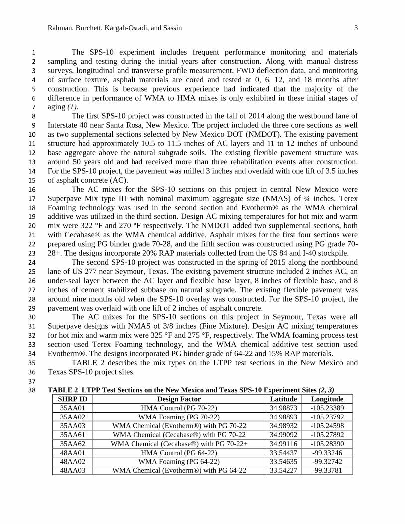
Evotherm®. The designs incorporated PG binder grade of 64-22 and 15% RAP materials. 34 TABLE 2 describes the mix types on the LTPP test sections in the New Mexico and 35
Texas SPS-10 project sites. 36 37
TABLE 2 LTPP Test Sections on the New Mexico and Texas SPS-10 Experiment Sites (2, 3) 38 SHRP ID Design Factor Latitude Longitude
35AA01 HMA Control (PG 70-22) 34.98873 -105.23389
35AA02 WMA Foaming (PG 70-22) 34.98893 -105.23792
35AA03 WMA Chemical (Evotherm®) with PG 70-22 34.98932 -105.24598
35AA61 WMA Chemical (Cecabase®) with PG 70-22 34.99092 -105.27892
35AA62 WMA Chemical (Cecabase®) with PG 70-22+ 34.99116 -105.28390
48AA01 HMA Control (PG 64-22) 33.54437 -99.33246
48AA02 WMA Foaming (PG 64-22) 33.54635 -99.32742
48AA03 WMA Chemical (Evotherm®) with PG 64-22 33.54227 -99.33781
Rahman, Burchett, Kargah-Ostadi, and Sassin 4
According to the LTPP SPS-10 experimental definition, both projects shall be considered 1
in the dry-no freeze climatic condition and high traffic category in the national experimental 2 matrix (TABLE 1). 3
4
The LTPP SPS-10 Construction Experience 5
Based on the experiences of the SRSC while monitoring the construction of the first two SPS-10 6
projects, the SRSC determined several considerations which require significant attention to 7 ensure the success of a research quality construction project. These considerations include 8 accurate collection of temperature and compaction information as well as consistent construction 9 practices such as steady state production of asphalt concrete and overlay layer thickness. While 10 the importance of these considerations may already be well known in the research community, 11
proper care must be taken to reliably accommodate them in the fast-paced and challenging 12 environment of an active construction site. 13
At the heart of the comparison between HMA and WMA pavements, production and 14 laydown temperatures are critical to the success of pavement research processes. While 15 recording temperatures may not be challenging, sufficient personnel must be available on site to 16 measure asphalt concrete temperatures often and in a consistent manner. The limitations of 17
measuring equipment must also be understood. For example, handheld infrared thermometers 18 often prescribe an optimal height from the surface to hold the device when in use. Inconsistent 19 measuring heights will lead to inconsistent temperature readings. Additionally, while many 20
asphalt concrete plants have the capability to measure production temperatures, sufficient 21 coordination prior to construction should be completed to guarantee sufficient temperatures are 22
recorded throughout the construction process. 23 The mixing temperatures at the plant, mix temperature when dropped from a belly dump 24
truck, and the pavement laydown temperature at the back of the screed of the paving machine 25
were recorded. The average temperature measurements on the New Mexico and Texas SPS-10 26
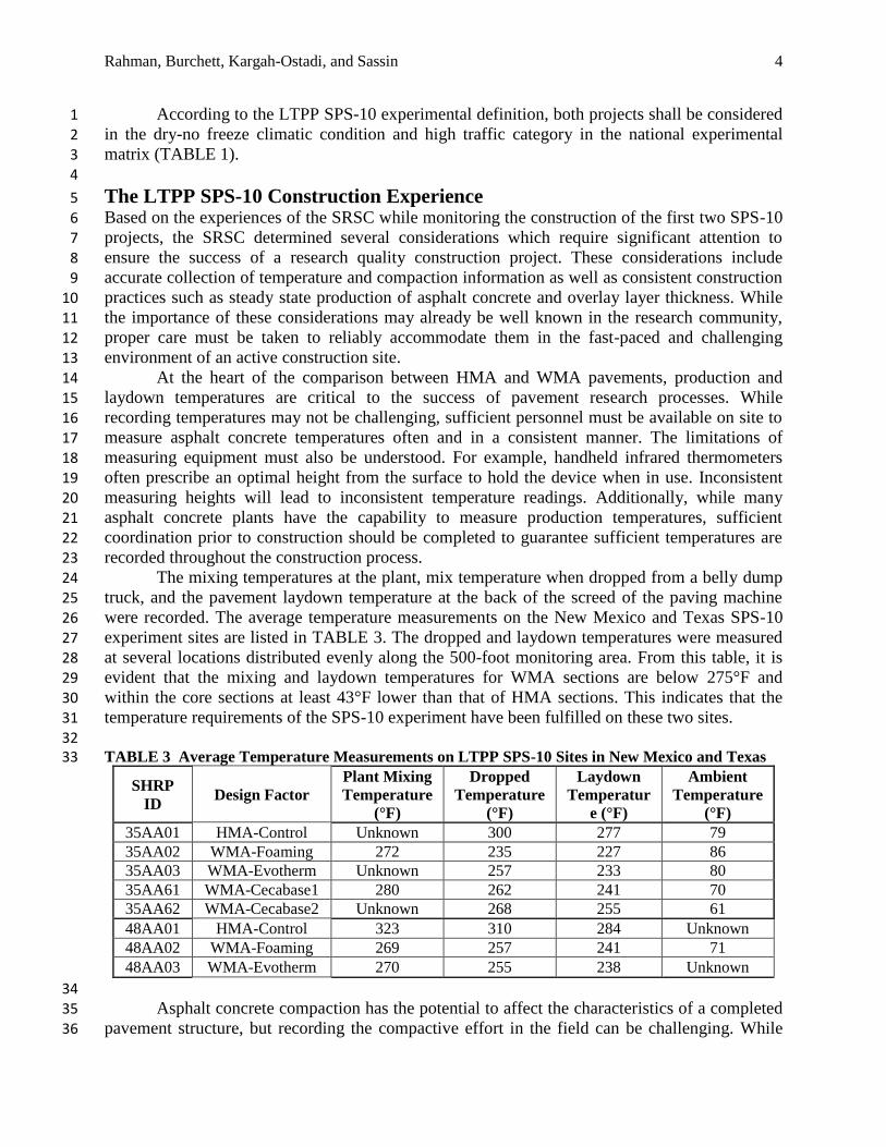
experiment sites are listed in TABLE 3. The dropped and laydown temperatures were measured 27 at several locations distributed evenly along the 500-foot monitoring area. From this table, it is 28 evident that the mixing and laydown temperatures for WMA sections are below 275°F and 29
within the core sections at least 43°F lower than that of HMA sections. This indicates that the 30 temperature requirements of the SPS-10 experiment have been fulfilled on these two sites. 31
32 TABLE 3 Average Temperature Measurements on LTPP SPS-10 Sites in New Mexico and Texas 33
SHRP
ID Design Factor
Plant Mixing
Temperature
(°F)
Dropped
Temperature
(°F)
Laydown
Temperatur
e (°F)
Ambient
Temperature
(°F)
35AA01 HMA-Control Unknown 300 277 79
35AA02 WMA-Foaming 272 235 227 86
35AA03 WMA-Evotherm Unknown 257 233 80
35AA61 WMA-Cecabase1 280 262 241 70
35AA62 WMA-Cecabase2 Unknown 268 255 61
48AA01 HMA-Control 323 310 284 Unknown
48AA02 WMA-Foaming 269 257 241 71
48AA03 WMA-Evotherm 270 255 238 Unknown
34 Asphalt concrete compaction has the potential to affect the characteristics of a completed 35
pavement structure, but recording the compactive effort in the field can be challenging. While 36

Rahman, Burchett, Kargah-Ostadi, and Sassin 5
equipment information such as type, weight, vibration frequency, and vibration amplitude are 1
important when comparing different projects, the number of passes completed by each piece of 2 compacting equipment can lead to great variability in compactive effort when comparing 3 different sections within the same project site. On site personnel should be dedicated to counting 4
the number of passes completed by each piece of compacting equipment for each test section. 5 Alternatively, a video camera may be set up to record the compaction process in case the 6 compactive effort at a particular test section is ever called into question. 7
The construction contractors and DOT personnel measured the bulk density and 8 compaction at three locations distributed evenly along the 500-foot monitoring area. New 9
Mexico used a nuclear density device; whereas a non-nuclear device was utilized in Texas 10 project to obtain the density. The average measured values for each test section are listed in 11 TABLE 4. The New Mexico test sections were constructed at five different days which possibly 12 incurred uneven density values among sections. As more laboratory testing results will become 13
available in the future, a more precise density measurement based on the extracted cores will be 14 available in the LTPP database. 15
16 TABLE 4 Average Density Measurements on LTPP SPS-10 Sites in New Mexico and Texas (2, 3) 17
SHRP ID Design Factor Average Bulk Density
(pcf)
Average %
Compaction
35AA01 HMA-Control 143.3 92.5
35AA02 WMA-Foaming 142.8 91.3
35AA03 WMA-Evotherm 139.5 90.2
35AA61 WMA-Cecabase1 144.6 93.5
35AA62 WMA-Cecabase2 142.8 91.8
48AA01 HMA-Control 143.2 93.4
48AA02 WMA-Foaming 141.2 93.3
48AA03 WMA-Evotherm 142.7 93.7
18
Although it may be challenging for interested research personnel to influence the 19 construction practices used for a research quality test section, consistent construction practices 20 can help ensure the success of a pavement research project. When asphalt concrete with different 21
characteristics, such as HMA and WMA, are produced by the same plant, it is critical that steady 22
state production of asphalt concrete is reached for each technology. Sufficient time and space 23 should be provided while switching between asphalt concrete technologies to allow the plant and 24
field personnel full adjust to the new mix. Layer thickness is another factor which can greatly 25 impact experimental results. Extra care should be practiced to ensure consistent lift thickness, but 26 elevation surveys before and after construction and ground penetrating radar (GPR) 27
measurements can capture the construction variability in layer thickness. 28 29
Analysis of Initial FWD Deflection Measurements 30
In this section of the paper, results of a preliminary analysis on FWD data collected before and 31
after overlay construction on the two initial SPS-10 sites are discussed. Pavement surface 32 deflections were measured at 11 test points at 50-foot intervals along each test section on the 33 outer wheel path and the mid-lane locations across the width. The FWD load was dropped four 34 times (repetitions) from four different drop heights. In order to capture the full variability in the 35 recorded values, all of the resulting 16 deflection basins at each test point were used 36

Rahman, Burchett, Kargah-Ostadi, and Sassin 6
independently for this analysis and deflection basins from different drops were not averaged 1
together. 2 The deflection data from all the 8 sensors (at offsets from 0 to 1,524 mm) and all 16 3 drops along the mid-lane of the 3 core sections on the New Mexico SPS-10 site are shown in 4
FIGURE 1, FIGURE 2, and FIGURE 3. In these figures, all of the deflection values from before 5 and after the overlay construction have been normalized to a plate pressure of 565 kPa, which is 6 the pressure caused by a standard 40kN load under a plate with 150 mm radius. 7
8
9 FIGURE 1 FWD Deflection Profiles Before and After Overlay on the New Mexico SPS-10 Site: 10 35AA01 – HMA Control Section 11
12
13 FIGURE 2 FWD Deflection Profiles Before and After Overlay on the New Mexico SPS-10 Site: 14 35AA02 – WMA Foaming Section 15
0
50
100
150
200
250
0 50 100 150
Norm
ali
zed
Def
lect
ion
(m
icro
ns)
Distance (m)
35AA01 Before Overlay
0
50
100
150
200
250
0 50 100 150
Norm
ali
zed
Def
lect
ion
(m
icro
ns)
Distance (m)
35AA01 After Overlay
0
50
100
150
200
250
0 50 100 150
No
rma
lize
d D
efle
ctio
n (
mic
ron
s)
Distance (m)
35AA02 Before Overlay
0
50
100
150
200
250
0 50 100 150
No
rma
lize
d D
efle
ctio
n (
mic
ron
s)
Distance (m)
35AA02 After Overlay

Rahman, Burchett, Kargah-Ostadi, and Sassin 7
1
2 FIGURE 3 FWD Deflection Profiles Before and After Overlay on the New Mexico SPS-10 Site: 3 35AA03 – WMA Chemical (Evotherm®) Section 4 5
It is clear from these figures that the overlays have improved the structural capacity of 6 these pavement sections, which is reflected in the lower deflection values closer to the center of 7
the load. However, no specific trends can be inferred from these figures as a significant 8 difference between the performance of the WMA and HMA sections. 9
At the next step of the analysis, the AASHTO 1993 overlay design methodology, which 10 is a widely accepted and practiced procedure among practitioners, is used to estimate the overall 11 pavement stiffness before and after the overlays on each test section (4). The deflections 12 measured at the center of the FWD load plate are normalized according to the measured 13 pavement temperature at the time of FWD testing. Then closed-form solutions are used to 14
estimate the resilient modulus of the subgrade soil, and subsequently the equivalent elastic 15
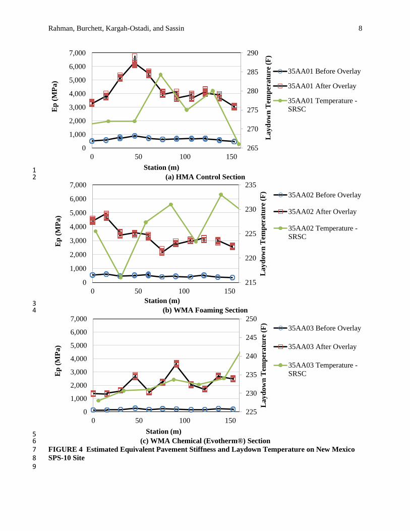
modulus (stiffness) of the pavement structure above the subgrade. 16 FIGURE 4 and FIGURE 5 demonstrate the equivalent stiffness estimated for the New 17
Mexico and Texas SPS-10 sites before and after overlay. These figures also indicate the 18 measured pavement laydown temperatures to investigate whether higher temperatures at the time 19 of compaction result in pavement overlays with higher stiffness. To answer that question, it is 20
important to note the change in equivalent elastic modulus as a result of the overlay. No definite 21 trend can be observed between the gain in stiffness and the laydown temperature. 22
While in the New Mexico site (FIGURE 4), the control section has gained more stiffness 23 as a result of the HMA overlay compared to the other WMA overlays, the chemical WMA 24 section is demonstrating the highest gain in stiffness in the Texas site (FIGURE 5). This suggests 25 that the observed differences in the stiffness are predominantly a result of construction variability 26 and cannot be attributed to the differences in mix and laydown temperatures. 27
0
50
100
150
200
250
0 50 100 150
No
rma
lize
d D
efle
ctio
n (
mic
ron
s)
Distance (m)
35AA03 Before Overlay
0
50
100
150
200
250
0 50 100 150
No
rma
lize
d D
efle
ctio
n (
mic
ron
s)
Distance (m)
35AA03 After Overlay
Rahman, Burchett, Kargah-Ostadi, and Sassin 8
1 (a) HMA Control Section 2
3 (b) WMA Foaming Section 4
5 (c) WMA Chemical (Evotherm®) Section 6
FIGURE 4 Estimated Equivalent Pavement Stiffness and Laydown Temperature on New Mexico 7 SPS-10 Site 8 9
265
270
275
280
285
290
0
1,000
2,000
3,000
4,000
5,000
6,000
7,000
0 50 100 150
La
yd
ow
n T
emp
era
ture
(F
)
Ep
(M
Pa
)
Station (m)
35AA01 Before Overlay
35AA01 After Overlay
35AA01 Temperature -
SRSC
215
220
225
230
235
0
1,000
2,000
3,000
4,000
5,000
6,000
7,000
0 50 100 150
Layd
ow
n T
emp
eratu
re (
F)
Ep
(M
Pa)
Station (m)
35AA02 Before Overlay
35AA02 After Overlay
35AA02 Temperature -
SRSC
225
230
235
240
245
250
0
1,000
2,000
3,000
4,000
5,000
6,000
7,000
0 50 100 150
La
yd
ow
n T
emp
eratu
re (
F)
Ep
(M
Pa)
Station (m)
35AA03 Before Overlay
35AA03 After Overlay
35AA03 Temperature -
SRSC

Rahman, Burchett, Kargah-Ostadi, and Sassin 9
1 (a) HMA Control Section 2
3 (b) WMA Foaming Section 4
5 (c) WMA Chemical (Evotherm®) Section 6
FIGURE 5 Estimated Equivalent Pavement Stiffness and Laydown Temperature on Texas SPS-10 7 Site 8 9
276
278
280
282
284
286
288
290
0
500
1000
1500
2000
0 50 100 150
La
yd
ow
n T
emp
era
ture
(F
)
Ep
(M
Pa)
Station (m)
48AA01 Before Overlay
48AA01 After Overlay
48AA01 Temperature -
SRSC
48AA01 Temperature -
IR Profile
230
235
240
245
250
255
0
500
1000
1500
2000
0 50 100 150
Layd
ow
n T
emp
eratu
re (
F)
Ep
(M
Pa)
Station (m)
48AA02 Before Overlay
48AA02 After Overlay
48AA02 Temperature -
SRSC
48AA02 Temperature -
IR Profile
230
235
240
245
250
0
500
1000
1500
2000
0 50 100 150
La
yd
ow
n T
emp
eratu
re (
F)
Ep
(M
Pa)
Station (m)
48AA03 Before
Overlay
48AA03 After Overlay
48AA03 Temperature -
SRSC
48AA03 Temperature -
IR Profile

Rahman, Burchett, Kargah-Ostadi, and Sassin 10
The average amount of increase in pavement stiffness as a result of HMA and WMA 1
overlays is displayed in FIGURE 6 and FIGURE 7 for the New Mexico and Texas SPS-10 sites, 2 respectively. The same observations as in FIGURE 4 and FIGURE 5 can be made here. While 3 both test sites used Evotherm® chemical additive in their core test sections, the foaming 4
technology has resulted in a higher stiffness compared to the chemical additive for the New 5 Mexico project, and the opposite is true for Texas project. This difference between the two sites 6 could be attributed to the differences in achieved density according to TABLE 4, where the 7 reported density is higher for the foaming WMA in the New Mexico project and for the chemical 8 WMA in the Texas project. However, the reported density does not explain the differences 9
between HMA and WMA mixes: The density of the HMA mixes in both sites is greater than the 10 WMA mixes, but the chemical WMA overlay on the Texas site has provided more stiffness 11 compared to the HMA overlay. It is important to note that these are only preliminary results and 12 as these pavement mixes are further compacted under the traffic loads, the differences in 13
densities between the test sections at every site will probably decrease. 14
15 FIGURE 6 Average Change in Equivalent Stiffness as a Result of the HMA and WMA Overlays on 16 New Mexico SPS-10 Sites 17 18
19 FIGURE 7 Average Change in Equivalent Stiffness as a Result of the HMA and WMA Overlays on 20 Texas SPS-10 Sites 21
0
500
1000
1500
2000
2500
3000
3500
4000
4500
5000
HMA Control WMA Foaming WMA
Evotherm
WMA
Cecabase1
WMA
Cecabase2
Ch
an
ges
in
Ep
(M
pa
)
Test Section
0
100
200
300
400
500
600
700
800
900
HMA Control WMA Foaming WMA Evotherm
Ch
an
ges
in
Ep
(M
Pa
)
Test Section

Rahman, Burchett, Kargah-Ostadi, and Sassin 11
It would be worthwhile to note that the primary mix design factor for the overall 1
construction project at New Mexico and Texas was WMA foaming and WMA chemical with 2 Evotherm®, respectively, which finally produced higher stiffness gain among the WMA 3 sections. Finally, it should be noted that the post-overlay FWD testing in New Mexico was 4
conducted in December, when the subgrade was probably frozen. This is reflected in the 5 significantly higher pavement stiffness indicated in FIGURE 6 for the New Mexico site 6 compared to FIGURE 7 for the Texas site. As future FWD testing cycles provide additional data, 7 the stiffness values need to be revisited. 8
9
CONCLUSIONS 10
This paper provided a brief overview of the observations made during the construction of the 11
first LTPP SPS-10 project sites. From an examination of the field measured construction 12 temperatures, the HMA and WMA sites have been constructed according to the experiment 13
requirements. The collected FWD deflection data before and after the HMA and WMA overlays 14 were examined to investigate any potential differences between the two mixes. Closed form 15 solutions from the AASHTO 1993 design guide were employed to estimate the equivalent 16 pavement stiffness before and after each overlay. The results indicated that while the increase in 17
stiffness was higher in the HMA control section in one project, the gain in stiffness was higher in 18 the WMA overlay in the other project. From this initial evaluation, no definite trends could be 19 identified between the pavement laydown temperature and the amount of stiffness gained. 20
Further investigation and materials testing is required to paint the full picture. As performance 21 monitoring and materials sampling and testing continues with time on these LTPP sections, 22
further robust details might emerge regarding the long-term performance of warm mix 23 technologies compared to the conventional hot mix. 24 25
26
REFERENCES 27
1. Puccinelli, J., P. Schmalzer, K. Senn, and L. McDonald, Long-Term Pavement 28 Performance Warm Mix Asphalt Study, Draft Final Report, Contract No. DTFH61-12-C-29
00017, Long-Term Pavement Performance Program, Office of Infrastructure Research 30 and Development, Federal Highway Administration, 2014. 31
2. Rahman, M.T., T.J. Burchett, N. Kargah-Ostadi, J.F. Daleiden, and J.M. Sassin, LTPP 32
SPS-10 Project 35AA00: Warm Mix Asphalt Overlay Study Along Westbound Lane of I-33 40 in Guadalupe County, New Mexico, Draft Construction Report, Long-Term Pavement 34 Performance Program, Office of Infrastructure Research and Development, Federal 35 Highway Administration, 2015. 36
3. Burchett, T.J., M.T. Rahman, N. Kargah-Ostadi, J.F. Daleiden, and J.M. Sassin, LTPP 37
SPS-10 Project 48AA00: Warm Mix Asphalt Overlay Study Along Northbound Lane of 38
US 277 in Baylor County, Texas, Draft Construction Report, Long-Term Pavement 39
Performance Program, Office of Infrastructure Research and Development, Federal 40 Highway Administration, 2015. 41
4. AASHTO. AASHTO Guide for Design of Pavement Structures. American Association of 42 State Highway and Transportation Officials, Washington, D.C., 1993. 43