london city airport cadp airfield drainage, ducting and ... drainage and taxiway... · appendix a...
TRANSCRIPT

Airfield Drainage, Ducting and Taxiway Links A400-XX-K-PQQ-00006
Airfield Drainage, Ducting and Taxiway Links Page 1 of 30
Status: USE Document Number: 1320-18-000-GPX-UR-ZQ-00001
Date: October 2017 Reason for Issue: IFU – Issued for Use
Revision: 00 Document Uncontrolled When Printed
London City Airport
CADP Airfield Drainage, Ducting and Taxiway Links
Pre-Qualification Questionnaire (PQQ)
Ref: A400-XX-K-PQQ-00006
October 2017
Disclaimer: This PQQ and the associated Contract Notice are non-binding subject to contract. LCY is
not subject to the Utilities Regulations and the PQQ and Contract Notice are for publicity purposes only.

Airfield Drainage, Ducting and Taxiway Links A400-XX-K-PQQ-00006
Airfield Drainage, Ducting and Taxiway Links Page 2 of 30
Status: USE Document Number: 1320-18-000-GPX-UR-ZQ-00001
Date: October 2017 Reason for Issue: IFU – Issued for Use
Revision: 00 Document Uncontrolled When Printed
Table of Contents
1.0 Introduction ............................................................................................................ 3 1.1 Abbreviations .......................................................................................................... 3 1.2 Our Business .......................................................................................................... 3 1.3 London City Airport – CADP Airfield Drainage and Taxi-way Works ....................... 4 1.3.1 The Programme ..................................................................................................... 4 1.3.2 Scope of the CADP Airfield Drainage and Taxiway Links ....................................... 4 1.3.3 Contractor Attributes ............................................................................................... 6 1.3.4 Programme ............................................................................................................ 7 1.4 PQQ Request ......................................................................................................... 7 1.5 Evaluation of PQQ Responses ............................................................................... 8 2.0 Instructions ............................................................................................................. 9 2.1 Requirements for Further Participation ................................................................... 9 2.2 Queries ................................................................................................................. 10 2.3 Next Steps ............................................................................................................ 10 2.4 Non-Reimbursement of Expenses ........................................................................ 10 2.5 Format of Response ............................................................................................. 10 2.6 Completeness of Response .................................................................................. 11 3.0 PQQ – Company Information ............................................................................... 12 3.1 Contact Details ..................................................................................................... 12 3.2 Company Information (Pass/Fail) .......................................... 13 4.0 PQQ – Fundamental Questions (Pass/Fail) .......................................... 16 4.1. Annual Turnover ................................................................................................... 16 4.2. Insurance ............................................................................................................. 16 4.3 Health & Safety Performance ............................................................................... 17 4.4 Environmental Qualification .................................................................................. 17 4.5 Quality & Quality Systems .................................................................................... 17 4.6 Human Resources Management .......................................................................... 17 5.0 PQQ – Experience................................................................................................ 18 5.1 Previous Company experience and references .................................................... 18 5.2 Competency and Capability – Resources ............................................................. 19 5.3 Project and Construction Management ................................................................. 20 5.4 Commitment to Client Overarching Objectives ..................................................... 21 5.5 Added Value ......................................................................................................... 21
Appendices
Appendix A Format for Client References ………………………………… 22
Appendix B Health and Safety Questionnaire ……………………………. 23
Appendix C Environment Questionnaire ………………………………….. 26
Appendix D Quality Questionnaire …………………………………………. 27
Appendix E Human Resources Questionnaire …………………………… 28
Appendix F General Project Information ………………………………….. 30

Airfield Drainage, Ducting and Taxiway Links A400-XX-K-PQQ-00006
Airfield Drainage, Ducting and Taxiway Links Page 3 of 30
Status: USE Document Number: 1320-18-000-GPX-UR-ZQ-00001
Date: October 2017 Reason for Issue: IFU – Issued for Use
Revision: 00 Document Uncontrolled When Printed
1.0 Introduction
1.1 Abbreviations
CADP City Airport Development Programme
CIP Capital Investment Programme
D&B Dunn & Bradstreet Report
EOI Expression of Interest
GMT Greenwich Meantime
LCY London City Airport
N/A Not Applicable
JV Joint Venture
PQQ Pre-Qualification Questionnaire
RIBA Royal Institute of British Architects
RFP Request for Proposal
1.2 Our Business
London City Airport Limited (LCY) operates a single runway airport that is located a few
miles east of Canary Wharf, London.
The scope of our airport operations is broad, covering all aspects of terminal,
passenger and baggage management, as well as administering the property and retail
businesses. As such, the airport works closely with a broad group of stakeholders,
including but not limited to airlines, the civil aviation authority, retailers and public
transport operators, to ensure a seamless experience for our customers.
This PQQ is thus issued for publicity purposes only. LCY does not consider itself to be
a Utility for purposes of the Regulations nor bound by the timeframes set out in the
Regulations. LCY shall voluntarily use a Restricted Procedure pursuant to the Utilities
Regulations.
To find out more about our business, please view our website on
www.londoncityairport.com.

Airfield Drainage, Ducting and Taxiway Links A400-XX-K-PQQ-00006
Airfield Drainage, Ducting and Taxiway Links Page 4 of 30
Status: USE Document Number: 1320-18-000-GPX-UR-ZQ-00001
Date: October 2017 Reason for Issue: IFU – Issued for Use
Revision: 00 Document Uncontrolled When Printed
1.3 London City Airport – CADP Airfield Drainage and Taxi-way Works
LCY wishes to appoint either a single contractor or a selection of contractors depending
upon the responses to this PQQ and associated Contract Notice to support its work to
plan and execute the future development of London City Airport pursuant to the
planning approval of the City Airport Development Programme (CADP). The purpose of
this contract is to complete the Employer provided design (nominal RIBA 3) and
construct taxiway/ links, airfield drainage works and link to the new concrete deck
drainage system including oil separator and attenuation tank and complete ducting
works for the airfield ground lights.
1.3.1 The Programme
LCY has permission to proceed with a programme of major capital works over the next
5 years to expand the existing airport infrastructure including additional aircraft stands,
east passenger terminal extension, associated baggage handling, security and other
works. The first phase of the Programme broadly consists of:
1. Terminal Works (extension to the West Terminal and baggage handling area
along with reconfiguration of the existing Terminal, construction of a new East
Pier and its connection to the main terminal);
2. Airfield Works (new aircraft stands, reconfiguration of some existing stands,
demolition of existing dolphin structure, construct floating Rendezvous Point,
Vehicle Control Point and permanent noise barrier);
3. Dockside Works (to improve the access and parking);
4. Enabling Works; and
5. Supporting Infrastructure (Western and Eastern Energy Centres).
1.3.2 Scope of the CADP Airfield Drainage and Taxiway Links
The works consists of the following:
Drainage
Drainage scope includes the installation of a gravity drainage system to serve the new
airfield aprons, parallel taxiway and amendments to hold 27. The drainage system will
consist of circa 20no manholes, varying pipe sizes connecting into a 170m long x 3m

Airfield Drainage, Ducting and Taxiway Links A400-XX-K-PQQ-00006
Airfield Drainage, Ducting and Taxiway Links Page 5 of 30
Status: USE Document Number: 1320-18-000-GPX-UR-ZQ-00001
Date: October 2017 Reason for Issue: IFU – Issued for Use
Revision: 00 Document Uncontrolled When Printed
wide x 2.1m deep attenuation chamber. The attenuation chamber in turn will be
connected to an oil separator and pumping station. The pumping station will pump
surface water to a new connection point on the existing surface water system to be
located in the region of taxiway Charlie.
Surfacing/ Tie-in works
Due to the construction of the new aprons and parallel taxiway new and amended
links are required for the connections to the runway. The works comprise provision of
all necessary people, plant, equipment, materials, temporary works and consumables
to complete the tie-in works.
Airfield Ground Lighting (AGL) ducting
A new pit and duct system is required to connect the areas of new taxiway and links to
the AGL systems. The scope of work within this package will be the pit and duct
system which sit in the clear and graded area of the runway connecting into the new
pit and duct system being constructed by the Piling and Deck package contractor.
These works are to be carried out outside airport operational times:
London City Airport maximum permitted operating hours are as follows:
Winter Summer (UTC)
Weekdays 06:30 - 22:00 05:30 - 21:00
Saturdays 06:30 - 12:30 05:30 - 11:30
Sundays 12:30 - 22:00 11:30 - 21:00
Public Holidays 09:00 - 22:00 08:00 – 21:00
Where access to the Airfield is required Airfield works may be undertaken during the
following hours:
Winter Summer (UTC)
Weekdays 22:30 - 05:30 21:30 - 04:30
Saturdays 00:00 - 05:30 & 13:00 -
23:59
00:00 - 04:30 & 12:00 –
23:59
Sundays 00:00 - 11:30 & 22:30 –
23:59
00:00 - 10:30 & 21:30 –
23:59

Airfield Drainage, Ducting and Taxiway Links A400-XX-K-PQQ-00006
Airfield Drainage, Ducting and Taxiway Links Page 6 of 30
Status: USE Document Number: 1320-18-000-GPX-UR-ZQ-00001
Date: October 2017 Reason for Issue: IFU – Issued for Use
Revision: 00 Document Uncontrolled When Printed
Public Holidays By Arrangement By Arrangement
1.3.3 Contractor Attributes
The contractors are expected to have the following attributes which LCY considers
necessary to successfully provide the work:
Relevant Experience – Demonstrable experience of the provision of major
construction works including works substantially similar to the major elements of,
and undertaken in a similar environment (Airside within runway strip) to, the
proposed Airfield Drainage and taxiway works;
Financial Strength – Contractors must be of sufficient size, have relevant
resources and the financial status to be classed as capable to reliably deliver major
works similar to those required in performance of the CADP Airfield Drainage and
Taxiway works;
Competency and Capability – Contractors must possess the necessary resources
and relevant skills to complement their history of experience in the successful
delivery of major works similar to those required in performance of the CADP
Airfield Drainage and Taxiway works;
Excellent Health, Safety & Environmental Record; and
Interest & Commitment – Contractors must be able to demonstrate both ability
and a history of commitment to supporting client overarching objectives and policy
goals.
LCY Key Objectives are:
1. Safety as a primary value – target of zero accidents;
2. Execution methodologies that minimise adverse impacts to LCY’s customers
using the airport and which deliver the requirements of airport operations
and stakeholders as planned;
3. Delivery of high quality, technically compliant works;
4. Delivery to programme and in accordance with contract terms;
5. Price competitiveness;
Airfield Drainage, Ducting and Taxiway Links A400-XX-K-PQQ-00006
Airfield Drainage, Ducting and Taxiway Links Page 7 of 30
Status: USE Document Number: 1320-18-000-GPX-UR-ZQ-00001
Date: October 2017 Reason for Issue: IFU – Issued for Use
Revision: 00 Document Uncontrolled When Printed
6. Fostering integrated collaborative teamwork, open communication and early
and fair resolution of issues in delivering capital projects.
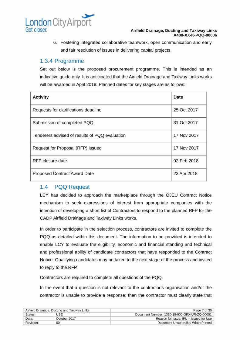
1.3.4 Programme
Set out below is the proposed procurement programme. This is intended as an
indicative guide only. It is anticipated that the Airfield Drainage and Taxiway Links works
will be awarded in April 2018. Planned dates for key stages are as follows:
Activity Date
Requests for clarifications deadline 25 Oct 2017
Submission of completed PQQ 31 Oct 2017
Tenderers advised of results of PQQ evaluation 17 Nov 2017
Request for Proposal (RFP) issued 17 Nov 2017
RFP closure date 02 Feb 2018
Proposed Contract Award Date 23 Apr 2018
1.4 PQQ Request
LCY has decided to approach the marketplace through the OJEU Contract Notice
mechanism to seek expressions of interest from appropriate companies with the
intention of developing a short list of Contractors to respond to the planned RFP for the
CADP Airfield Drainage and Taxiway Links works.
In order to participate in the selection process, contractors are invited to complete the
PQQ as detailed within this document. The information to be provided is intended to
enable LCY to evaluate the eligibility, economic and financial standing and technical
and professional ability of candidate contractors that have responded to the Contract
Notice. Qualifying candidates may be taken to the next stage of the process and invited
to reply to the RFP.
Contractors are required to complete all questions of the PQQ.
In the event that a question is not relevant to the contractor’s organisation and/or the
contractor is unable to provide a response; then the contractor must clearly state that

Airfield Drainage, Ducting and Taxiway Links A400-XX-K-PQQ-00006
Airfield Drainage, Ducting and Taxiway Links Page 8 of 30
Status: USE Document Number: 1320-18-000-GPX-UR-ZQ-00001
Date: October 2017 Reason for Issue: IFU – Issued for Use
Revision: 00 Document Uncontrolled When Printed
the answer is Not Applicable (N/A) with a statement explaining why the question is not
relevant to the contractor’s organisation.
Contractors should send the completed PQQ along with supporting documents to LCY
Delivery Partner Document Control by email at
[email protected] by the deadline. Only submissions to the
said e-mail address will be accepted.
LCY will be using the NEC3 Engineering and Construction Contract, Main Option A with
amendments. LCY reserves the right to change the proposed contract or any of its
terms should a different basis be decided prior to award.
1.5 Evaluation of PQQ Responses
For the purposes of the PQQ, contractors are to demonstrate their creditworthiness,
capability and experience by answering the questions and providing required
information in the following sections:
Section 3 – Company Information including financial information;
Section 4 – Fundamentals including Health and Safety information; and
Section 5 – Experience.
Questions contained in this PQQ will be marked either numerically or on a Pass-Fail,
as described below and the information provided will form part of the selection criteria
used for the assessment of contractors.
Requirements in Section 3 are intended to demonstrate a contractor’s financial strength
and capability to perform the services. Questions in Section 3 are marked on a “Pass”
or “Fail” basis. Submission of the required information/documentation which
demonstrates compliance with a pass/ fail requirement or positive approach to
discharge of legal and financial obligations equates to a “Pass” whereas submission of
inadequate material or no material equates to a “Fail”. Submissions that receive a “Fail”
will be disqualified from further participation.
Responses to questions in Section 4 will also be assessed on a “Pass” or “Fail” basis.
Any submissions that receive a “Fail” will be disqualified from further participation.
Submission of the required information/documentation equates to a “Pass” whereas
submission of inadequate material or no material equates to a “Fail”.

Airfield Drainage, Ducting and Taxiway Links A400-XX-K-PQQ-00006
Airfield Drainage, Ducting and Taxiway Links Page 9 of 30
Status: USE Document Number: 1320-18-000-GPX-UR-ZQ-00001
Date: October 2017 Reason for Issue: IFU – Issued for Use
Revision: 00 Document Uncontrolled When Printed
Each question in Section 5 will be marked on a scale of 0 to 10 based upon the
completeness, relevance and clarity of the response, including the breadth, depth and
value of a contractor’s capabilities to LCY as evidenced by the submission.
Marks are allocated as follows:
0 No information provided or what is provided is irrelevant;
1 – 2 Minimum information provided, statements vague or unclear as to
relevance;
3 – 4 Information substantial but incomplete, of limited relevance and
unsatisfactory;
5 – 6 Information incomplete but generally relevant and satisfactory;
7 – 8 Information generally complete, comprehensive, relevant and
satisfactory; and
9 – 10 Answered fully with information being relevant, comprehensive and
completely satisfactory.
Each question in Section 5 has a weighting as indicated which is applied to the mark
for that question. The weighted mark for each question is then totalled to give an
overall mark.
The overall pass mark to progress to the next stage will be 70% but this may be
adjusted as determined by LCY should circumstances warrant it. LCY may select a
short list of qualified contractors with reference to their respective ranking based on the
weighted total scores.
2.0 Instructions Interested contractors must submit responses to this PQQ by 23:59 GMT Tuesday,
31st October 2017. Responses shall be submitted electronically to a nominated email
address as per section 1.4 above.
No responses will be accepted by LCY after the time and date as set out above.
2.1 Requirements for Further Participation To be considered for further participation, candidate contractors must complete and
return the required information as detailed in this PQQ.

Airfield Drainage, Ducting and Taxiway Links A400-XX-K-PQQ-00006
Airfield Drainage, Ducting and Taxiway Links Page 10 of 30
Status: USE Document Number: 1320-18-000-GPX-UR-ZQ-00001
Date: October 2017 Reason for Issue: IFU – Issued for Use
Revision: 00 Document Uncontrolled When Printed
Registering interest in this project and/or submitting a completed response does not
guarantee inclusion of the candidate into the tender enquiry list.
2.2 Queries Any queries or questions concerning this stage of the process or document must be
referred not later than 25th October 2017 directly to LCY Contact Officer: Vegain Doola
(email: [email protected])
All communication and correspondence must be in the English Language.
2.3 Next Steps The responses to the PQQ will be marked individually and scored as per the marking
scheme set out herein.
On the basis of the score, LCY intends to shortlist a number of selected contractors for
the next stage of the tender process. A detailed tender timetable will be provided to the
contractors short listed for this initiative.
Following the PQQ evaluation process, LCY will notify all responsive contractors
whether or not they will proceed to the next phase.
2.4 Non-Reimbursement of Expenses LCY will not reimburse any expenses incurred by any respondents as a result of their
involvement with responding to this document, attending interviews and/or any other
aspects of the process
2.5 Format of Response Each question must be read carefully and an appropriate answer provided. A separate
answer must be provided in the space or format detailed for each question. Answers
must be concise and not exceed the permitted limit. Answers over the prescribed limit
will not be evaluated and scored at zero.
Responses to the questions must be specific to this PQQ. The submission of generic
information, general brochures, marketing information and general information is not
required.
Responses must be submitted in Adobe Acrobat PDF electronic format and using the
code specified in the contract notice to which this PQQ is attached as single documents
or as otherwise requested, or detailed in this PQQ.

Airfield Drainage, Ducting and Taxiway Links A400-XX-K-PQQ-00006
Airfield Drainage, Ducting and Taxiway Links Page 11 of 30
Status: USE Document Number: 1320-18-000-GPX-UR-ZQ-00001
Date: October 2017 Reason for Issue: IFU – Issued for Use
Revision: 00 Document Uncontrolled When Printed
2.6 Completeness of Response An incomplete or inadequate response to any question may result in disqualification
from further consideration as described in Section 1.5.

Airfield Drainage, Ducting and Taxiway Links A400-XX-K-PQQ-00006
Airfield Drainage, Ducting and Taxiway Links Page 12 of 30
Status: USE Document Number: 1320-18-000-GPX-UR-ZQ-00001
Date: October 2017 Reason for Issue: IFU – Issued for Use
Revision: 00 Document Uncontrolled When Printed
3.0 PQQ – Company Information
3.1 Contact Details Contractor is to provide complete contact details as per the table format provided below
for two representatives for the purposes of this process.
These individuals should ideally be:
A Director or equivalent; or
Bid Manager.
A. Primary Contact (Senior Manager)
Name:
Title:
Address:
Telephone:
Fax:
Mobile:
Email:
B. Alternate Contact
Name:
Title:
Address:
Telephone:
Fax:
Mobile:
Email:

Airfield Drainage, Ducting and Taxiway Links A400-XX-K-PQQ-00006
Airfield Drainage, Ducting and Taxiway Links Page 13 of 30
Status: USE Document Number: 1320-18-000-GPX-UR-ZQ-00001
Date: October 2017 Reason for Issue: IFU – Issued for Use
Revision: 00 Document Uncontrolled When Printed
3.2 Company Information (Pass/Fail)
3.2.1 Organisation
Contractor is to provide a Company summary, including:
a) Name, head office address, company number and other key details;
b) Brief history of the Company, including details of any changes of ownership
over the last 5 years;
c) An organisational chart defining close parent, sister and subsidiary companies,
and the relevant division of the company; and
d) Details of any significant pending developments, changes in financial structure
or ownership, prospective takeover bids, buyouts and closures, etc., which are
currently in the public domain.
This section can be submitted via a separate attachment of no more than two
single sided A4 pages of 1.5 spaced lines using Arial typeface size 11 for text.
With specific reference to the requirements of the required works, provide an
organisation chart for the Company, detailing the number of staff and their role (e.g.
technical, non-technical, managerial, specialist) in each group, department, location
etc.
Contractor to restrict its response to no more than two single sided A4 pages of
1.5 spaced lines using Arial typeface size 11 for text.
If contractor’s intended proposal will comprise an existing or proposed Joint Venture
(JV) or consortium arrangement, provide the above information for all members of the
JV or consortium, as well as the following details of the JV or consortium arrangement:
a) The relationship between the companies; and
b) The proposed breakdown of the workload (which company will be responsible
for which activities including nomination of the lead JV partner).

Airfield Drainage, Ducting and Taxiway Links A400-XX-K-PQQ-00006
Airfield Drainage, Ducting and Taxiway Links Page 14 of 30
Status: USE Document Number: 1320-18-000-GPX-UR-ZQ-00001
Date: October 2017 Reason for Issue: IFU – Issued for Use
Revision: 00 Document Uncontrolled When Printed
Contractor to restrict its response to no more than one single sided A4 page of
1.5 spaced lines using Arial typeface size 11 for text.
a)
b)
3.2.2 Financial
Contractor to submit:
a) A full Dunn & Bradstreet (D&B) company report, obtained in the last month. If
the contractor, or the relevant division of the contractor, is a subsidiary, part of
another organisation, or any other type of entity which results in a D&B report
being of little or no value, then the contractor is to explain why;
b) Full financial accounts for the past 3 years; and
c) Details of the contractor’s projected turnover and operating profits for the
upcoming 3 years.
d) Has your company or any of its Directors and Executive Officers been the
subject of criminal or civil court action (including for bankruptcy or insolvency) in
respect of the business activities currently engaged in, for which the outcome
was a judgement against you or them?
Please provide details of any such action. Responses will be taken into account
in assessing the outcome of this prequalification application where the
circumstances of the judgement are pertinent to anticipated future projects or
services. They will not necessarily constitute a reason for rejection.
e) If your company or any of its Directors and/ or Executive Officers are the subject
of ongoing or pending criminal or civil court action (including for bankruptcy or
insolvency) in respect of the business activities currently engaged in, have all
claims been properly notified in accordance with the suppliers Professional
indemnity or Product Liability Insurance policy requirements and been accepted
by insurers?

Airfield Drainage, Ducting and Taxiway Links A400-XX-K-PQQ-00006
Airfield Drainage, Ducting and Taxiway Links Page 15 of 30
Status: USE Document Number: 1320-18-000-GPX-UR-ZQ-00001
Date: October 2017 Reason for Issue: IFU – Issued for Use
Revision: 00 Document Uncontrolled When Printed
Please provide details of action and confirmation, with references of the
relevant notification and insurer acceptance. Responses will be taken into
account as part of the assessment process.
f) Has your company or any of its Directors and Executive Officers been in receipt
of enforcement/remedial orders that are still unresolved, in the last three years?
Please provide details, including the status of the required action. Responses
will be taken into account as part of the assessment process.
a)
b)
c)
d)
e)
f)

Airfield Drainage, Ducting and Taxiway Links A400-XX-K-PQQ-00006
Airfield Drainage, Ducting and Taxiway Links Page 16 of 30
Status: USE Document Number: 1320-18-000-GPX-UR-ZQ-00001
Date: October 2017 Reason for Issue: IFU – Issued for Use
Revision: 00 Document Uncontrolled When Printed
4.0 PQQ – Fundamental Questions (Pass/Fail) A satisfactory response to all of the questions in this section must be provided in
order for the responses to Section 5 (following) to be considered.
The information requested in this section must be provided for all proposed members
of a JV or consortium.
4.1. Annual Turnover For the CADP Airfield Drainage and Taxiway Links contract LCY requires contractors
to have an annual turnover in non-residential Construction in excess of £50 million
per annum over the last 3 years. If contractor responds as a consortium or joint
venture the total annual turnover of the consortium or joint venture will apply.
The contractor is to confirm its annual turnover over the last 3 years meets this
criterion
Answer YES or NO
Turnover for 2015/2016:
Turnover for 2014/2015:
Turnover for 2013/2014:
4.2. Insurance The contractor is to provide insurance details, with particular reference to:
a) Employer’s Liability (EL);
b) Public Liability (PL);
c) Professional Indemnity Insurance (PII);
d) If currently available, Airside Indemnity Insurance (as endorsement to Public
Liability or separately)
Provide the insurer, policy number, expiry date, limit of cover, policy excess and any
exclusions and confirm minimum PII and PL cover.

Airfield Drainage, Ducting and Taxiway Links A400-XX-K-PQQ-00006
Airfield Drainage, Ducting and Taxiway Links Page 17 of 30
Status: USE Document Number: 1320-18-000-GPX-UR-ZQ-00001
Date: October 2017 Reason for Issue: IFU – Issued for Use
Revision: 00 Document Uncontrolled When Printed
Contractor to restrict its response to no more than two single sided A4 pages of 1.5
spaced lines using Arial typeface size 11 for text.
a)
b)
c)
d)
4.3 Health & Safety Performance The contractor is to provide a complete response to the Health and Safety
Questionnaire attached hereto marked as Appendix B.
Contractor is to restrict its response to no more than the completed Health & Safety
Questionnaire and requested supporting documentation
4.4 Environmental Qualification The contractor is to provide complete response to the Environmental Questionnaire
attached hereto marked as Appendix C
Contractor is to restrict its response to completed Environmental Questionnaire and
supporting documents
4.5 Quality & Quality Systems The contractor is to provide a complete response to the Quality Questionnaire attached
hereto marked as Appendix D
Contractor is to restrict its response to completed Quality Questionnaire and
supporting documents
4.6 Human Resources Management The contractor is to provide a complete response to the Human Resources
management attached hereto marked as Appendix E

Airfield Drainage, Ducting and Taxiway Links A400-XX-K-PQQ-00006
Airfield Drainage, Ducting and Taxiway Links Page 18 of 30
Status: USE Document Number: 1320-18-000-GPX-UR-ZQ-00001
Date: October 2017 Reason for Issue: IFU – Issued for Use
Revision: 00 Document Uncontrolled When Printed
Contractor is to restrict its response to completed Human Resources Questionnaire
and supporting documents
5.0 PQQ – Experience The information required by this Section 5 must be provided for all proposed members
of a JV or consortium. Certain words and phrases have been identified in bold type is
to assist the contractor to focus on identifying and responding to those areas
important to LCY.
5.1 Previous Company experience and references
(Weighting 50%)
The contractor is to provide:
a) A summary of specific experience as a contractor with responsibility for the
delivery of Airfield Drainage, AGL Ducting Works and taxiway PQ works, with
particular reference to commissions carried out for major projects. Where
possible, provide evidence of working on a range of different types of airport
that demonstrates the breadth of the contractor’s experience with
examples of how this has been deployed to the benefit of other clients.
Where possible include examples of projects undertaken in an operating
environment (e.g. at airports or marine ports). (10%)
b) Three examples of each specific area of experience (drainage ducting taxiway)
(30%). Each of the examples is to provide a synopsis of the works and services
provided which should include the following:
A short description stating:
o the name and location of the works;
o project scope description including the size and value of the works;
o the year completed;
o details of your role on the project, approximate overall project value
and the value of the contractor’s element;
o the type of contract; and
o an indication of out-turn against budget and programme.

Airfield Drainage, Ducting and Taxiway Links A400-XX-K-PQQ-00006
Airfield Drainage, Ducting and Taxiway Links Page 19 of 30
Status: USE Document Number: 1320-18-000-GPX-UR-ZQ-00001
Date: October 2017 Reason for Issue: IFU – Issued for Use
Revision: 00 Document Uncontrolled When Printed
Examples of risk identification / mitigation in connection with similarly
scoped work and/or examples of instances where innovation or proprietary
technology were used to your client’s advantage.
Details of delethalisation implications and solutions provided.
Description of equipment including, as appropriate, marine support
equipment highlighting any safety and environmental aspects that might
be relevant to the LCY scope.
c) References (10%)
Note: All references should be within the last 5 years.
In the event of consortia or JVs, the specific references of each member must
be clearly detailed.
Client’s reference details for each of the projects listed above are to be provided
in the format shown in Appendix A.
Contractor is to restrict its response to no more than the below stated limits for single
sided A4 pages for each section above of 1.5 spaced lines using Arial typeface size 11
for text.
a) two pages
b) three pages per example
c) completed reference form
5.2 Competency and Capability – Resources
(Weighting 20%)
(a) The contractor is to provide information on the extent and range of skills that it
has available in its organization including provision of a breakdown of managerial
and supervisory manpower available, specifically identifying capacity and
availability of the type of key resource required to perform the proposed Airfield
Drainage contract. The contractor should identify the key positions necessary to
safely and effectively provide the Airfield Drainage works along with the expected
level of experience and qualifications of people assigned to such key positions. For

Airfield Drainage, Ducting and Taxiway Links A400-XX-K-PQQ-00006
Airfield Drainage, Ducting and Taxiway Links Page 20 of 30
Status: USE Document Number: 1320-18-000-GPX-UR-ZQ-00001
Date: October 2017 Reason for Issue: IFU – Issued for Use
Revision: 00 Document Uncontrolled When Printed
identified key positions the contractor may provide details in the form of short
sample CVs for individuals considered appropriate.
(b) The contractor is to provide information on the number and type of Equipment
appropriate to the scope that it has available in its organization. The contractor
should identify equipment that it owns, that it would hire, and equipment that would
be provided under subcontracted scope. The contractor should identify any
specialist Equipment and any constraints on availability of which the contractor
might currently be aware.
(a) Contractor is to restrict its response to no more than two single sided A4
pages of 1.5 spaced lines using Arial typeface size 11 for text to summarise
organizational resources and individual CVs are to be concise and specific and
comprise no more than two single sided A4 pages.
(b) Contractor is to restrict its response to no more than two single sided A4s
5.3 Project and Construction Management
(Weighting 20%)
The contractor is to provide a summary of its project and construction management
processes used to deliver scopes broadly equivalent to the CADP Airfield Drainage and
Taxiway Links works. The contractor is also to provide a summary Project Execution
Plan from a previous Airfield Drainage contract (or for previous contract demonstrably
involving similar construction elements) which is sufficiently comprehensive to
demonstrate how it plans to deliver the works.
Contractor is to restrict its response to no more than four single sided A4 pages of
1.5 spaced lines using Arial typeface size 11 for text plus a summary execution
plan(s) of no more than ten single sided A4 pages of 1.5 spaced lines using Arial
typeface size 11 for text

Airfield Drainage, Ducting and Taxiway Links A400-XX-K-PQQ-00006
Airfield Drainage, Ducting and Taxiway Links Page 21 of 30
Status: USE Document Number: 1320-18-000-GPX-UR-ZQ-00001
Date: October 2017 Reason for Issue: IFU – Issued for Use
Revision: 00 Document Uncontrolled When Printed
5.4 Commitment to Client Overarching Objectives
(Weighting 5%)
The contractor is to provide a summary of its understanding of, and an explanation of
how it will commit to adopt and deliver in line with LCY’s key objectives. The summary
must be precise and comprehensive enough to demonstrate in factual terms how the
contractor will embed its commitment into its CADP Airfield Drainage and Taxiway
activities.
Contractor is to restrict its response to no more than 500 words (word count to be
shown).
5.5 Added Value
(Weighting 5%)
The contractor is to describe how it will bring added value to LCY in the delivery of
CADP Airfield Drainage and Taxiway Links works, giving examples of how this has
been successfully achieved on other contracts. Particular areas which the
contractor’s submission should address are: continuous improvement, applying lessons
learned, developing and applying creative solutions and the use of best practice.
Contractor is to restrict its response to no more than 500 words (word count to be
shown).

Airfield Drainage, Ducting and Taxiway Links A400-XX-K-PQQ-00006
Airfield Drainage, Ducting and Taxiway Links Page 22 of 30
Status: USE Document Number: 1320-18-000-GPX-UR-ZQ-00001
Date: October 2017 Reason for Issue: IFU – Issued for Use
Revision: 00 Document Uncontrolled When Printed
Appendix A
Format for Client References (Q5)
Question 5.1 part c): Client References for each project example
Project Title:
…………………………………………………………….…………………………………………………….
Tender Value: …………………………………………………………….
Final Account Value: …………………………………………………………….
Value of Works Undertaken by your Company: …………………………………
Procurement Route: …………………………………………………………………
(State whether design and construct or employer design)
Role under CDM (if any)……………………………………………………………….
Awards Received: ………………………………………………………………….….
Form of Contract: …………………………………………………………………..….
a) Client Reference
Name of Organisation: ……………………………………………………….
Name of Contact: ………………………………………………………….….
Address: …………………………………………………………………….…
……………………………………….……………………………………….…
Telephone Number: ……………………………………………………….….
Email Address: ………………………………………………………..………
b) Client Project Manager/Contract Administrator
Name of organisation: ………………………………………………………..
Name of Contact: ……………………………………………………………..
Address: …………………………………………………………….…...…….
…………………………………………………………………………………..
Telephone Number: …………………………………………………………..
Email Address: ………………………………….…………………………….
c) Client’s Cost Manager
Name of Organisation: ……………………………………………………….
Name of Contact: ………………………………………………………….….
Address: …………………………………………………………………….…
…………………………………………………………………….…………….
Telephone Number: …………………………………………………….…….
Email Address: …………………………..……………………………………

Airfield Drainage, Ducting and Taxiway Links A400-XX-K-PQQ-00006
Airfield Drainage, Ducting and Taxiway Links Page 23 of 30
Status: USE Document Number: 1320-18-000-GPX-UR-ZQ-00001
Date: October 2017 Reason for Issue: IFU – Issued for Use
Revision: 00 Document Uncontrolled When Printed
Appendix B
QUESTION 4.3 – HEALTH AND SAFETY
Please attach a copy of your Health and Safety Policy Statement
How are the policy and relevant health and safety information communicated to staff?
What is the management level of the person owning the Health & Safety policy?
Management level Name
What is the name of the Health & Safety Manager?
If you have a dedicated Health and Safety Manager what are his/ her qualifications (IOSH/ NEBOSH/etc.)?
Qualifications:
If you have no Health & Safety Manager how do you meet your responsibilities for the Health and Safety at Work Act 1974?
Details:
In brief, how do you manage Health and Safety?
How do you monitor ongoing compliance with your Health and Safety procedures?
Has your company received any awards or citations for good health and safety management arrangements in the past 5 years
YES NO
Do you have a standard risked assessed method statement indicating safe working methods for your area(s) of work? (tick box by typing a ‘’)
YES NO
If yes, please attach copies:

Airfield Drainage, Ducting and Taxiway Links A400-XX-K-PQQ-00006
Airfield Drainage, Ducting and Taxiway Links Page 24 of 30
Status: USE Document Number: 1320-18-000-GPX-UR-ZQ-00001
Date: October 2017 Reason for Issue: IFU – Issued for Use
Revision: 00 Document Uncontrolled When Printed
Describe how you ensure that staff, including subcontractors and casual labour, are fully trained and have the relevant skills.
Please provide evidence of Training matrix
Please provide details of sub-contractor vetting procedures for Health & Safety:
Number of notified (RIDDOR) incidents you have recorded in last 3 years: No.
Number of fatalities recorded in the last 5 years? No.
Has your company or a subcontractor working on your behalf over the past 5 years been, or is in the process of being, investigated/ prosecuted for any Health & Safety offence? If the answer to the question is ‘Yes’, please provide a full explanatory statement. Failure to provide information may result in disqualification.
Has your company over the past 5 years been, or is in the process of, having any civil action brought against it for any Health & Safety offence? If the answer to the question is ‘Yes’, please provide a full explanatory statement. Failure to provide information may result in disqualification.
How will you ensure that your company and any sub-contractors will comply with LCY’s Local Site Rules, Health and Safety Policy?

Airfield Drainage, Ducting and Taxiway Links A400-XX-K-PQQ-00006
Airfield Drainage, Ducting and Taxiway Links Page 25 of 30
Status: USE Document Number: 1320-18-000-GPX-UR-ZQ-00001
Date: October 2017 Reason for Issue: IFU – Issued for Use
Revision: 00 Document Uncontrolled When Printed
Does your company have a CDM 2015 policy? If “yes” provide a copy.
Does your company have a written Drug/Substance Abuse Policy with Testing? If “yes” provide a copy. What type(s): [ ] Pre-employment [ ] Post Accident [ ] Just Cause [ ] Random

Airfield Drainage, Ducting and Taxiway Links A400-XX-K-PQQ-00006
Airfield Drainage, Ducting and Taxiway Links Page 26 of 30
Status: USE Document Number: 1320-18-000-GPX-UR-ZQ-00001
Date: October 2017 Reason for Issue: IFU – Issued for Use
Revision: 00 Document Uncontrolled When Printed
Appendix C
QUESTION 4.4 – ENVIRONMENTAL MANAGEMENT
Please provide copies of your Environmental policies and arrangements
What is the management level of the person owning the Environmental policy?
Management level: Name:
What is the name of the Manager responsible for the Environment?
Management level: Name:
In brief, how do you manage Environmental issues?
List the environmental aspects associated with the product/ service you will be supplying to LCY and describe the approach you will adopt to minimise the impact to the environment.
Are you ISO 14001 certified (tick box by typing a ‘’)? YES NO
Please attach a copy of the certificate How do you monitor ongoing compliance with your Environmental procedures:
Do you assess life cost of products you purchase? YES NO
What measures do you take to minimise the environmental impact of the following: Waste, Re Cycling, Energy Usage, Packaging and Paper?
Do you offer facilities for suppliers to return your used product or packaging for recycling or safe disposal? YES NO
Have you been convicted of breaching any environmental legislation in the last 5 years by the Environment Agency or a Local Authority? YES NO
If ‘yes’ to the forgoing please provide basic details:

Airfield Drainage, Ducting and Taxiway Links A400-XX-K-PQQ-00006
Airfield Drainage, Ducting and Taxiway Links Page 27 of 30
Status: USE Document Number: 1320-18-000-GPX-UR-ZQ-00001
Date: October 2017 Reason for Issue: IFU – Issued for Use
Revision: 00 Document Uncontrolled When Printed
Appendix D
QUESTION 4.5 – QUALITY MANAGEMENT
YES NO PLEASE TICK AS APPROPRIATE /COMMENTS
Does your company maintain a formal documented quality management system relevant to the intended scope of the Contract?
Is your system certified to ISO9001:2015 for the scope of the Contract? (please attach copy of certificate)
If the answer to above question is 'No'; please provide the following:
(a) Does the company intend to achieve certification? If so when?
(b) Company Quality Manual (c) Quality Policy (d) Listing of management system procedures
(including current revision status) (e) Organisation chart illustrating QA and QC positions
Do you have arrangements for ensuring that your quality management, including the quality of construction output and general performance, is effective in reducing/preventing incidents of sub-standard delivery?

Airfield Drainage, Ducting and Taxiway Links A400-XX-K-PQQ-00006
Airfield Drainage, Ducting and Taxiway Links Page 28 of 30
Status: USE Document Number: 1320-18-000-GPX-UR-ZQ-00001
Date: October 2017 Reason for Issue: IFU – Issued for Use
Revision: 00 Document Uncontrolled When Printed
Appendix E
QUESTION 4.6 – HUMAN RESOURCES MANAGEMENT
What is your approach to people management? Please list and provide evidence of the following policies:
Policy How is this Policy Managed
Right to work in UK
Equality Policy
Modern Slavery Act
Do you have a dedicated HR Manager? (tick box by typing a ‘’) YES NO
If YES please what is their name:
What is the concept of their role?
Do you have any external recognition, e.g. IIP? If YES please provide a copy of certificate
YES NO
Please provide details of memberships, awards and professional qualifications pertaining to your profession or trade? Copies to be attached:
Please explain and give details of your approach to induction for new staff and staff training Attach copies of documentation if necessary:
How do you ensure employees are aware of their rights (tick box by typing a ‘’)?
Written Contracts Employee Handbook Staff notice boards Intranet
Other – Please Detail

Airfield Drainage, Ducting and Taxiway Links A400-XX-K-PQQ-00006
Airfield Drainage, Ducting and Taxiway Links Page 29 of 30
Status: USE Document Number: 1320-18-000-GPX-UR-ZQ-00001
Date: October 2017 Reason for Issue: IFU – Issued for Use
Revision: 00 Document Uncontrolled When Printed
Please indicate ways in which you consult employees about decisions which affect them, and get their feedback or ideas (tick box by typing a ‘’)
Meetings Surveys Suggestion Box
Other- Please Detail
What are the normal working hours for employees? Is overtime voluntary?
Yes No
Is it paid at a premium rate? Yes No What is the youngest age at someone
can be employed by the company
Please provide details of the following information covering the last 3 years
Year 2016 2015 2014
Staff turnover rate % % %
Number of directly employed staff
Average length of service of current permanent staff
Average training spend per member of staff
Describe below any recent, current or future initiatives intended to influence the quality of work, culture or attitudes of staff within your organisation:

Airfield Drainage, Ducting and Taxiway Links A400-XX-K-PQQ-00006
Airfield Drainage, Ducting and Taxiway Links Page 30 of 30
Status: USE Document Number: 1320-18-000-GPX-UR-ZQ-00001
Date: October 2017 Reason for Issue: IFU – Issued for Use
Revision: 00 Document Uncontrolled When Printed
Appendix F
General Project Information
Drawings:
Reference Title Rev Date
A400-TPS-C-00-L00-DR-GA-864-001 Airfield Drainage Layout - Sheet 1 07 08/09/17
A400-TPS-C-00-L00-DR-GA-864-002 Airfield Drainage Layout - Sheet 2 05 08/09/17
A400-TPS-C-00-L00-DR-GA-864-003 Airfield Drainage Layout - Sheet 3 05 08/09/17
A400-TPS-C-00-L00-DR-GA-864-004 Airfield Drainage Layout - Sheet 4 04 08/09/17
A400-TPS-C-00-XXX-DR-SE-864-201 Proposed Drainage Longitudinal
Sections Sheet 1 of 6 03 08/09/17
A400-TPS-C-00-XXX-DR-SE-864-202 Proposed Drainage Longitudinal
Sections Sheet 2 of 6 03 08/09/17
A400-TPS-C-00-XXX-DR-SE-864-203 Proposed Drainage Longitudinal
Sections Sheet 3 of 6 03 08/09/17
A400-TPS-C-00-XXX-DR-SE-864-204 Proposed Drainage Longitudinal
Sections Sheet 4 of 6 03 08/09/17
A400-TPS-C-00-XXX-DR-SE-864-205 Proposed Drainage Longitudinal
Sections Sheet 5 of 6 03 08/09/17
A400-TPS-C-00-XXX-DR-SE-864-206 Proposed Drainage Longitudinal
Sections Sheet 6 of 6 03 08/09/17

23
2425 26
22
21
OTHER
Q 400
F 50
OTHER
Q 400
F 50
5
09-27 09-27 09-27
1
11
1
T
A
X
I
W
A
Y
E
C
H
O
TA
XIW
AY
C
HA
RLIE
T
A
X
I
W
A
Y
D
E
L
T
A
123
VENT CHAMBER
VENT CHAMBER VENT CHAMBERVENT CHAMBER
0.6m
Bagg
age C
ollec
tion A
rea
68sq
m
4
Baggage BeltPres. Len = 37.0 mTotal Len = 48.4 m
3
Pres. Len = 35.7 mTotal Len = 48.1 m
Bagg
age C
ollec
tion A
rea
66.9
sqm
Bagg
age C
ollec
tion A
rea
78.3
sqm
Bagg
age C
ollec
tion A
rea
78.4
sqm
2
Baggage BeltPres. Len = 36.5 mTotal Len = 47.4 m
1
Pres. Len = 37.7 mTotal Len = 52.1 m
1
Pres. Len = 32.9 mTotal Len = 48.2 m
Bagg
age C
ollec
tion A
rea
82.4
sqm
AIRSIDELANDSIDE
CU
T L
IN
E
CO
NT
IN
UE
D A
BO
VE
L
V
L
V
L
V
L
V
L
V
LV
LV
LV
LV
LV
LV
LV
LV
LV
LV
LV
LV
LV
LV
LV
LV
LV
LV
LV
LV
LV
LV
LV
LV
LV
LV
LV LV LV
LV
LV LV LV
LV
LV LV LV
LV
LV LV LV
LV
LV LV LV
LV
LV
LV
LV
LV
LV
LV
LV
LV
LV
LV
LV
LV
LV
LV
LV
SW
SW
SW
SW
SW
SW
SW
SW
SW
SW
SW
SW
SW
SW
CP 1
CP 2
CP 3
MH 11-14
SWSW
SWSW
SWSW
SWSW
SW
SWSW
SWSW
SWSW
SWSW
SWSW
SWSW
SW
SW(P)
SW(P)
SW(P)
SW(P)
SW(P)
SW(P)
SW(P)
SW(P)
SW(P)
SW(P)
SW(P)
SW(P)
SW(P)
SW(P)
SW(P)
SW(P)
SW(P)
SW(P)
SW(P)
MH 11-16
MH 11-15
MH 11-13
MH 11-12
∅ 600mm∅ 600mm
SW
SW
SW
SW
SW
SW
SW
∅ 45
0m
m
MH 22-1
SW SW SW SW SW
MH 22-2
∅ 450mm
∅ 750mm
S
W
S
W
S
W
S
W
S
W
S
W
S
W
S
W
S
W
S
W
S
W
S
W
S
W
∅ 22
5
m
m
∅ 22
5
m
m
∅ 22
5
m
m
CP 4
400 SLOT DRAIN
PUMPING
STATION
1
5
0
S
L
O
T
D
R
A
I
N
VALVE
CHAMBER
PUMPING MAIN 630O/D SDR11
OR SIMILAR IN DUCTILE IRON
3 No. 450/406
PUMPING MAIN
Ø 750mm
1
5
0
S
L
O
T
D
R
A
I
N
150 S
LO
T D
RA
IN
400 SLOT DRAIN
PUMP OUTFALL
CHAMBER
∅ 600mm ∅ 600mm
LEGEND:
DRAINAGE PIPE
DRAINAGE PRESSURE PIPE
SLOT DRAIN
PIT DRAINAGE (INDICATIVE)
DRAINAGE MANHOLE
SLOT DRAIN CATCHPIT
PROPOSED LV DUCTS
SW SW
LV LV
SW(P) SW(P)
CP 2
MH 22-2
09-27
TA
XIW
AY
C
HA
RLIE
VENT CHAMBER VENT CHAMBERVENT CHAMBER
CU
T LIN
E
CO
NT
IN
UE
D B
ELO
W
MH 11-18
SW SW SW SW SW SW SW
SWSW
SWSW
SWSW
SWSW
SWSW
SW
MH 11-17
MH 11-16
∅ 600mm∅ 600mm
∅ 600
m
m
EX CP
Project
Drawing Title
Originating Office
TPS Job Manager
QA System - Checks
Drawn By:
Checked:
Authorised:
Signature Date
TPS Project No.Drawing Status
Scale (at A1) (at A3)
DO NOT SCALE FROM THIS DRAWING
Copyright in all documents and drawings prepared by TPS Consult Ltd. and in
any works executed from those documents and drawings shall remain the
property of TPS Consult Ltd. unless otherwise agreed at project inception.
Birmingham : Croydon : Edinburgh : Sheffield : Wolverhampton
TPS Croydon - Interchange
81-85 Station Road
Croydon
CR0 2RD
United Kingdom
Tel +44 (0)1902 422431
www.tpsconsult.co.uk
CITY AIRPORT
DEVELOPMENT PROGRAMME
P. MISTRY
112931
Rev.Project No. Orig. Disc. Zone Level Type Sht. No.Sub Type Series
A400-TPS-C-00-L00-DR-GA-864-001
L.OLARIU 06/11/2015
AIRFIELD
DRAINAGE LAYOUT
SHEET 1 OF 4
1:500D2 - FOR TENDER
W.HELLYER 06/11/2015
R.MOORE 06/11/2015
07
CO
NT
IN
UE
D O
N D
wg
.N
o. A
40
0-T
PS
-C
-0
0-L0
0-D
R-G
A-864-002
P1
L.OLARIU
06/11/2015
W.HELLYER
06/11/2015
STAGE 3 ISSUE
02
P.OFFER
12/07/16
W.HELLYER
12/07/16
STAGE 3 ISSUE
FOR TENDER
03
R.RYAN
14/11/2016
W.HELLYER
14/11/2016
TENDER ISSUE
NOTES
1. ALL DIMENSIONS IN METRES UNLESS
OTHERWISE STATED
2. FOR SURFACE WATER DRAINAGE
INSTALLATION DETAILS REFER TO
DRAWINGS A400-TPS-C-XXX-DR-DE-864-001
TO 006
3. AGL PITS TO BE PROTECTED FROM
BACKFLOW FROM DRAINAGE SYSTEM.
PILING AND DECK
PACKAGE BOUNDARY
04
R.RYAN
13/01/2017
P. MISTRY
13/01/2017
NOTE 2 REVISED.
05
R.RYAN
23/03/2017
P. MISTRY
23/03/2017
INSET ADDED
INSET
06
R.RYAN
12/05/2017
P. MISTRY
12/05/2017
AGL DRAINAGE IN DECK DELETED
SAFETY, HEALTH AND ENVIRONMENTAL INFORMATION
In addition to the hazards and risks normally associated with the type of work
detailed on this drawing. NOTE SIGNIFICANT HAZARDS AS IDENTIFIED
CONSTRUCTION:
FOR CONSTRUCTION, OPERATION, MAINTENANCE AND DEMOLITION
RISKS REFER TO COMBINED CADP RISK REGISTER:
A400-01-U-REG-00001-02
MAINTENANCE:
SEE ABOVE
DECOMISSIONING / DEMOLITION:
SEE ABOVE
It is assumed that all works will be undertaken by a competent contractor;
working where appropriate, to an approved method statement.
07
R.RYAN
08/09/2017
P. MISTRY
08/09/2017
STAGE 3 UPDATE ISSUE

2627
28
29 3031
32
1
1
11
1
11
1
SEGS MOUNTED
ON POST
TAXILANE
FLOODLIGHTING
MAST
FLOODLIGHTING
MAST
SIDES VMA 112
SW(P)
MH 11-13
MH 11-12
SW SW SW SW SW SW SW SW SW SW SW SW SW SW SW SW SW SW SW SW SW
∅ 750mm∅ 750mm∅ 750mm
MH 11-11 MH 11-10
SW
SW
SW
SW
SW
SW
SW
SW
SW
∅ 45
0m
m
MH 18-1
∅ 450mm
MH 18-2
∅ 45
0m
m
SW
SW
SW
SW
SW
SW
SW
SW
SW
MH 19-1
MH 19-2
∅ 45
0m
m
∅ 450mm
∅ 45
0m
m
SW
SW
SW
SW
SW
SW
SW
SW
SW
∅ 45
0m
m
MH 20-1
MH 20-2
∅ 450mm
∅ 45
0m
m
SW
SW
SW
SW
SW
SW
SW
SW
SW
SW
SW
SW
SW
SW
∅ 45
0m
m
∅ 450mm
MH 21-1
SW
SW
SW
SW
∅ 45
0m
m
MH 21-2
∅ 45
0m
m
MH 22-3
MH 23-1∅ 450mm
∅ 75
0m
m
SW SW SW SW SW SW SW
∅ 750mm
CP 5
CP 9
CP 8CP 7CP 6
PUMPING
STATION
3000W x 2100D BOX CULVERT
VALVE
CHAMBER
3 No. 450/406
PUMPING MAIN
Ø 750mm
Ø 750mm
400 SLOT DRAIN
Ø 750mm
ATTENUATION
TANK
PIER FOOTPRINT
DRAINING TO DOCK
400 SLOT DRAIN 400 SLOT DRAIN
400 SLOT DRAIN
400 SLOT DRAIN400 SLOT DRAIN 400 SLOT DRAIN
VALVE IN CHAMBER TO CLOSE
SYSTEM DURING AIRCRAFT DE-ICING
VALVE IN CHAMBER TO CLOSE
SYSTEM DURING AIRCRAFT DE-ICING
VALVE IN CHAMBER TO CLOSE
SYSTEM DURING AIRCRAFT DE-ICING
VALVE IN CHAMBER TO CLOSE
SYSTEM DURING AIRCRAFT DE-ICING
VALVE IN CHAMBER TO CLOSE
SYSTEM DURING AIRCRAFT DE-ICING
FULL RETENTION OIL SEPARATOR
FOR DETAILS SEE DRAWING
A400-TPS-C-00-XXX-DR-DE-864-001
1
L
V
L
V
L
V
L
V
L
V
L
V
L
V
LV
LV
LV
LV
LV
LV
LV
LV
LV
LV
LV
LV
LV
LV
LV
LV
LV
LV
LV
LV
LV
LV
LV
LV LV LV
ED
ED
ED
ED
ED
ED
ED
LV
LV
LV
LV
LV
LV
LV
LV
LV LV
LV
LV LV LV
LV
LV LV LV
LV
LV
LVLV
LV
LV LV LV
LV
LV LV LV
LV
LV LV LV
LV
LV
LV
LV
LV
LV
LV
LVLV
LV
LV
LV
LV
LV
LV
LV
LV
LV
LV
LV
LV
LV
LV
LV
LV
LV
LV
LV
LV
ED
ED
ED
ED
ED
ED
ED
LEGEND:
DRAINAGE PIPE
DRAINAGE PRESSURE PIPE
SLOT DRAIN
PIT DRAINAGE (INDICATIVE)
DRAINAGE MANHOLE
SLOT DRAIN CATCHPIT
PROPOSED LV DUCTS
SW SW
LV LV
SW(P) SW(P)
CP 2
MH 22-2
SD SD SD SD SD SD SD SD SD
Project
Drawing Title
Originating Office
TPS Job Manager
QA System - Checks
Drawn By:
Checked:
Authorised:
Signature Date
TPS Project No.Drawing Status
Scale (at A1) (at A3)
DO NOT SCALE FROM THIS DRAWING
Copyright in all documents and drawings prepared by TPS Consult Ltd. and in
any works executed from those documents and drawings shall remain the
property of TPS Consult Ltd. unless otherwise agreed at project inception.
Birmingham : Croydon : Edinburgh : Sheffield : Wolverhampton
TPS Croydon - Interchange
81-85 Station Road
Croydon
CR0 2RD
United Kingdom
Tel +44 (0)1902 422431
www.tpsconsult.co.uk
CITY AIRPORT
DEVELOPMENT PROGRAMME
P. MISTRY
112931
Rev.Project No. Orig. Disc. Zone Level Type Sht. No.Sub Type Series
A400-TPS-C-00-L00-DR-GA-864-002
L.OLARIU 06/11/2015
AIRFIELD
DRAINAGE LAYOUT
SHEET 2 OF 4
1:500D2 - FOR TENDER
W.HELLYER 06/11/2015
R.MOORE 06/11/2015
05
CO
NT
IN
UE
D O
N D
wg
.N
o. A
40
0-T
PS
-C
-00
-L
00-D
R-G
A-8
64-003
P1
L.OLARIU
06/11/2015
W.HELLYER
06/11/2015
STAGE 3 ISSUE
02
P.OFFER
12/07/16
W.HELLYER
06/11/2015
STAGE 3 ISSUE
FOR TENDER
03
R.RYAN
14/11/2016
W.HELLYER
14/11/2016
TENDER ISSUE
CO
NT
IN
UE
D O
N D
wg
.N
o. A
40
0-T
PS
-C
-00
-L
00-D
R-G
A-8
64-001
NOTES
1. ALL DIMENSIONS IN M UNLESS OTHERWISE
STATED
2. FOR SURFACE WATER DRAINAGE
INSTALLATION DETAILS REFER TO
DRAWINGS A400-TPS-C-XXX-DR-DE-864-001
TO 004
3. AGL PITS TO BE PROTECTED FROM
BACKFLOW FROM DRAINAGE SYSTEM.
PILING AND DECK
PACKAGE BOUNDARY
04
R.RYAN
12/05/2017
P. MISTRY
12/05/2017
AGL DRAINAGE IN DECK DELETED
SAFETY, HEALTH AND ENVIRONMENTAL INFORMATION
In addition to the hazards and risks normally associated with the type of work
detailed on this drawing. NOTE SIGNIFICANT HAZARDS AS IDENTIFIED
CONSTRUCTION:
FOR CONSTRUCTION, OPERATION, MAINTENANCE AND DEMOLITION
RISKS REFER TO COMBINED CADP RISK REGISTER:
A400-01-U-REG-00001-02
MAINTENANCE:
SEE ABOVE
DECOMISSIONING / DEMOLITION:
SEE ABOVE
It is assumed that all works will be undertaken by a competent contractor;
working where appropriate, to an approved method statement.
05
R. RYAN
08/09/2017
P. MISTRY
08/09/2017
STAGE 3 UPDATE ISSUE

31
32
1
1
11
TAXILANE
T
A
X
I
W
A
Y
F
O
X
T
R
O
T
SIDES VMA 112
CP 17
MH 16-1
SW SW SW SW SW SW SW SW SW SW SW SW SW SW SW SW SW SW SW SW SW SW SW SW SW SW SW SW SW SW SW SW SW SW SW SW SW SW SW SW SW SW SW SW SW SW SW SW SW SW SW SW SW
∅ 750mm ∅ 525mm
∅ 750mm
∅ 750mm∅ 750mm∅ 750mmMH 11-11 MH 11-10 MH 11-9
MH 11-8
MH 11-7
MH 11-6
SW
SW
SW
SW
SW
SW
SW
SW
SW
∅ 45
0m
m
MH 14-1
MH 14-2
∅ 450mm
∅ 45
0m
m
SW
SW
SW
SW
SW
SW
SW
S
W
S
W
MH 15-1
MH 15-2
∅ 45
0m
m
∅ 37
5m
m
S
W
S
W
S
W
∅ 30
0
m
m
SW
SW
SW
SW
SW
SW
SW
SW
SW
∅ 450mm
∅ 45
0m
m
SW
SW
SW
SW
SW
SW
SW
SW
SW
∅ 45
0m
m
MH 18-1
∅ 450mm
MH 18-2
∅ 45
0m
m
SW
SW
SW
SW
SW
SW
SW
SW
SW
MH 19-1
MH 19-2
∅ 45
0m
m
∅ 45
0m
m
CP 17CP 11
CP 10
CP 9
CP 8
∅ 45
0
m
m
MH 17-1
MH 17-2
S
W
S
W
∅ 37
5
m
m
∅ 375
m
m
CP 13
EX SWS 5
∅ 225mm
∅ 450mm∅ 225mm
∅ 225mm
∅ 45
0m
m
225 SLOT DRAIN225 SLOT DRAIN
225 SLOT DRAIN
3
0
0
S
L
O
T
D
R
A
I
N
3
0
0
S
L
O
T
D
R
A
I
N
225 SLOT DRAIN
225 SLOT DRAIN
225 SLOT DRAIN
CP 21
CP 22
CP 25
CP 29
400 SLOT DRAIN 400 SLOT DRAIN 400 SLOT DRAIN 400 SLOT DRAIN
400 SLOT DRAIN 400 SLOT DRAIN 400 SLOT DRAIN
VALVE IN CHAMBER TO CLOSE
SYSTEM DURING AIRCRAFT DE-ICING
VALVE IN CHAMBER TO CLOSE
SYSTEM DURING AIRCRAFT DE-ICING
CP 14
3
0
0
S
L
O
T
D
R
A
IN
S
W
S
W
4
0
0
S
L
O
T
D
R
A
I
N
LV
LV
LV
LV
LV
LV
LV
LV
LV
LV
LV
LV
LV
LV
LV
LV LV LV LV LV LV LV LV LV LV LV LV LV LV LV LV LV LV LV LV LV LV LV LV LV LV LV LV LV LV LV LV LV LV LV LV LV LV LV LV LV LV LV LV LV LV
LV LV
LV
LV LV LV
LV
LV
LV
LV
LV
LVLV
LV
LV
LV
LV
LV
LV
LV
LV
LV
AREA SAFEGUARDED FOR 3
FUTURE GHOST STANDS.
LEGEND:
DRAINAGE PIPE
DRAINAGE PRESSURE PIPE
SLOT DRAIN
PIT DRAINAGE (INDICATIVE)
DRAINAGE MANHOLE
SLOT DRAIN CATCHPIT
PROPOSED LV DUCTS
SW SW
LV LV
SW(P) SW(P)
CP 2
MH 22-2
SD SD SD SD SD SD SD SD SD
Project
Drawing Title
Originating Office
TPS Job Manager
QA System - Checks
Drawn By:
Checked:
Authorised:
Signature Date
TPS Project No.Drawing Status
Scale (at A1) (at A3)
DO NOT SCALE FROM THIS DRAWING
Copyright in all documents and drawings prepared by TPS Consult Ltd. and in
any works executed from those documents and drawings shall remain the
property of TPS Consult Ltd. unless otherwise agreed at project inception.
Birmingham : Croydon : Edinburgh : Sheffield : Wolverhampton
TPS Croydon - Interchange
81-85 Station Road
Croydon
CR0 2RD
United Kingdom
Tel +44 (0)1902 422431
www.tpsconsult.co.uk
CITY AIRPORT
DEVELOPMENT PROGRAMME
P. MISTRY
112931
Rev.Project No. Orig. Disc. Zone Level Type Sht. No.Sub Type Series
A400-TPS-C-00-L00-DR-GA-864-003
L.OLARIU 06/11/2015
AIRFIELD
DRAINAGE LAYOUT
SHEET 3 OF 4
1:500D2 - FOR TENDER
W.HELLYER 06/11/2015
R.MOORE 06/11/2015
05
CO
NT
IN
UE
D O
N D
wg.N
o. A
400-T
PS
-C
-00-L00-D
R-G
A-864-004
NOTES
1. ALL DIMENSIONS IN M UNLESS OTHERWISE
STATED
2. FOR SURFACE WATER DRAINAGE
INSTALLATION DETAILS REFER TO
DRAWINGS A400-TPS-C-XXX-DR-DE-864-001
TO 004
3. AGL PITS TO BE PROTECTED FROM
BACKFLOW FROM DRAINAGE SYSTEM.
P1
L.OLARIU
06/11/2015
W.HELLYER
06/11/2015
PRELIMINARY ISSUE
02
P.OFFER
06/11/2015
W.HELLYER
06/11/2015
PRELIMINARY ISSUE
FOR TENDER
03
R.RYAN
14/11/2016
W.HELLYER
14/11/2016
TENDER ISSUE
PILING AND DECK
PACKAGE BOUNDARY
CO
NT
IN
UE
D O
N D
wg.N
o. A
400-T
PS
-C
-00-L00-D
R-G
A-864-002
04
R.RYAN
12/05/2017
P. MISTRY
12/05/2017
AGL DRAINAGE IN DECK DELETED
SAFETY, HEALTH AND ENVIRONMENTAL INFORMATION
In addition to the hazards and risks normally associated with the type of work
detailed on this drawing. NOTE SIGNIFICANT HAZARDS AS IDENTIFIED
CONSTRUCTION:
FOR CONSTRUCTION, OPERATION, MAINTENANCE AND DEMOLITION
RISKS REFER TO COMBINED CADP RISK REGISTER:
A400-01-U-REG-00001-02
MAINTENANCE:
SEE ABOVE
DECOMISSIONING / DEMOLITION:
SEE ABOVE
It is assumed that all works will be undertaken by a competent contractor;
working where appropriate, to an approved method statement.
05
R. RYAN
08/09/2017
P. MISTRY
08/09/2017
STAGE 3 UPDATE ISSUE

T
A
X
I
W
A
Y
K
I
L
O
T
A
X
I
W
A
Y
L
I
M
A
TA
XIW
AY
M
IK
E
PROPOSED PARALLEL TAXILANE
SW SW SW SW SW SW SW SW SW SW SW SW SW SW SW SW
SW
SW
SW
SW
SW
SW
SW
SW
∅ 45
0m
m
∅ 52
5
m
m
∅ 4
50m
m
∅ 525mm ∅ 525mm
MH 11-6 MH 11-5
MH 11-4
MH 11-3
MH 11-1
MH 11-2
S
W
S
W
S
W
S
W
S
W
S
W
S
W
S
W
SW SWSW SW
SW SW
MH 12-3
∅ 45
0
m
m
∅ 30
0
m
m
MH 12-2
MH 12-1
SW
SW
SW
SW
SW
SW
SW
SW
SW
MH 13-1
MH 13-2
MH 14-2
∅ 45
0m
m
CP 17 CP 18 CP 19
S
W
S
W
SW
S
W
S
W
S
W
S
W
SW
SW
SW
SW
∅ 22
5
m
m
∅ 225m
m
∅ 22
5
m
m ∅ 225m
m
∅ 22
5
m
m
∅ 225mm
SW
SW
SW
SW
SW
SW
S
W
∅ 225mm
∅ 22
5
m
m
225 SLOT DRAIN
225 SLOT DRAIN
EX CP23
EX CP11
EX CP6
EX CP18
EX CP19
EX MH 20
MH 24-1
MH 24-2
CP 20
EX MH 7
EX MH 5
∅ 300m
m
∅ 300m
m
EX SWS 5
∅ 225mm
∅ 450mm
∅ 45
0m
m
∅ 300mm
225 SLOT DRAIN ∅ 450mm
225 SLOT DRAIN
∅ 225mm
∅ 225mm
225 SLOT DRAIN
CP 25
CP 26
CP 28
400 SLOT DRAIN 400 SLOT DRAIN 400 SLOT DRAIN
LV LV LV LV LV LV LV LV LV LV LV LV
L
V
LV LV
L
V
LV LV LV LV LV LV LV LV LV LV LV LV LV LV LV LV LV LV LV LV LV LV LV LV LV LV LV LV LV LV LV LV LV LV LV LV LV LV LV LV
L
V
L
V
L
V
L
V
L
V
L
V
L
V
L
V
L
V
LV
LV
LEGEND:
DRAINAGE PIPE
DRAINAGE PRESSURE PIPE
SLOT DRAIN
PIT DRAINAGE (INDICATIVE)
DRAINAGE MANHOLE
SLOT DRAIN CATCHPIT
PROPOSED LV DUCTS
SW SW
LV LV
SW(P) SW(P)
CP 2
MH 22-2
SD SD SD SD SD SD SD SD SD
Project
Drawing Title
Originating Office
TPS Job Manager
QA System - Checks
Drawn By:
Checked:
Authorised:
Signature Date
TPS Project No.Drawing Status
Scale (at A1) (at A3)
DO NOT SCALE FROM THIS DRAWING
Copyright in all documents and drawings prepared by TPS Consult Ltd. and in
any works executed from those documents and drawings shall remain the
property of TPS Consult Ltd. unless otherwise agreed at project inception.
Birmingham : Croydon : Edinburgh : Sheffield : Wolverhampton
TPS Croydon - Interchange
81-85 Station Road
Croydon
CR0 2RD
United Kingdom
Tel +44 (0)1902 422431
www.tpsconsult.co.uk
CITY AIRPORT
DEVELOPMENT PROGRAMME
P. MISTRY
112931
Rev.Project No. Orig. Disc. Zone Level Type Sht. No.Sub Type Series
A400-TPS-C-00-L00-DR-GA-864-004
P.OFFER 12/07/2016
AIRFIELD
DRAINAGE LAYOUT
SHEET 4 OF 4
1:500D2 - FOR TENDER
W.HELLYER 12/07/2016
04
Rev DateRevised By Checked By Date
01
P.OFFER
12/07/16
W.HELLYER
12/07/16
STAGE 3 ISSUE
02
R.RYAN
14/11/2016
W.HELLYER
14/11/2016
TENDER ISSUE
FOR TENDER
CO
NT
IN
UE
D O
N D
wg.N
o. A
400
-T
PS
-C
-0
0-L
00
-D
R-G
A-8
64-003
NOTES
1. ALL DIMENSIONS IN M UNLESS OTHERWISE
STATED
2. FOR SURFACE WATER DRAINAGE
INSTALLATION DETAILS REFER TO
DRAWINGS A400-TPS-C-XXX-DR-DE-864-001
TO 004
3. AGL PITS TO BE PROTECTED FROM
BACKFLOW FROM DRAINAGE SYSTEM.
03
R.RYAN
12/05/2017
P. MISTRY
12/05/2017
AGL DRAINAGE IN DECK DELETED
PILING AND DECK
PACKAGE BOUNDARY
SAFETY, HEALTH AND ENVIRONMENTAL INFORMATION
In addition to the hazards and risks normally associated with the type of work
detailed on this drawing. NOTE SIGNIFICANT HAZARDS AS IDENTIFIED
CONSTRUCTION:
FOR CONSTRUCTION, OPERATION, MAINTENANCE AND DEMOLITION
RISKS REFER TO COMBINED CADP RISK REGISTER:
A400-01-U-REG-00001-02
MAINTENANCE:
SEE ABOVE
DECOMISSIONING / DEMOLITION:
SEE ABOVE
It is assumed that all works will be undertaken by a competent contractor;
working where appropriate, to an approved method statement.
04
R. RYAN
08/09/2017
P. MISTRY
08/09/2017
STAGE 3 UPDATE ISSUE

LE
VE
L
LINE 11 LONG SECTION
SCALE: H = 1:500,V = 1:100
DATUM: 0.000
0
1
2
3
4
5
6
7
8
9
10
CHAINAGE
EXISTING GROUND
LEVELS
PROPOSED GROUND
LEVELS
SERVICE
INVERT LEVELS
SERVICE PIT
EASTING AND NORTHING
00.000
10.000
20.000
30.000
40.000
46.550
50.000
50.517
60.000
64.127
70.000
72.410
80.000
90.000
100.000
110.000
120.000
121.741
130.000
140.000
150.000
160.000
170.000
180.000
181.750
190.000
200.000
210.000
220.000
230.000
238.432
240.000
250.000
260.000
270.000
280.000
290.000
293.228
300.000
5.591
5.620
5.624
5.527
5.513
5.553
5.529
5.496
5.487
5.458
5.418
5.419
5.416
5.435
5.431
5.434
5.404
5.455
5.421
5.424
5.328
5.183
5.451
5.376
5.382
5.381
5.386
5.424
5.504
5.464
5.467
5.448
5.433
5.444
6.110
6.190
6.273
6.213
6.085
5.988
5.908
5.897
5.700
5.626
5.392
5.384
5.344
5.290
5.198
5.076
4.956
4.832
4.809
4.828
4.837
4.763
4.878
5.016
5.060
5.144
2.792
2.660
3.694
3.316
5.000
4.878
3.291
3.143
3.143
2.962
2.962
2.792
2.660
3.316
3.291
5.300
5.000
4.295
4.374
4.142
4.178
E: 543285.930
N: 180396.962
E: 543286.019
N: 180400.928
E: 543285.221
N: 180414.515
E: 543277.176
N: 180416.483
E: 543167.863
N: 180418.926
E: 543227.857
N: 180417.586
E: 543056.413
N: 180421.418
E: 543111.195
N: 180420.193
E: 543284.890
N: 180350.424
MH 11-7
MH 11-8
MH 11-6
MH 11-5
∅ 525mm ∅ 750mm ∅ 750mm
∅ 525mm
MH 11-4
∅ 525mm
MH 11-3
∅ 450m
m
MH 11-2
MH 11-1
∅ 450mm
∅ 450mm
CP 19
EX
IS
TIN
G 4X
2/100 LV
D
UC
T
PR
OP
OS
ED
3x2/100 LV
D
UC
T
PR
OP
OS
ED
3x2/100 LV
D
UC
T
PR
OP
OS
ED
3x2/100 LV
D
UC
T
PR
OP
OS
ED
300m
m S
LO
T D
RA
IN
PROPOSED 400mm
SLOT DRAIN
PR
OP
OS
ED
4x3/100 LV
D
UC
T
290.000
293.228
300.000
310.000
320.000
330.000
331.663
340.000
350.000
360.000
370.000
380.000
390.000
391.757
400.000
410.000
420.000
430.000
440.000
450.000
460.000
470.000
480.000
481.721
490.000
495.277
500.000
510.000
520.000
530.000
540.000
541.721
550.000
560.000
570.000
580.000
590.000
5.448
5.433
5.444
5.412
5.435
5.402
5.386
5.391
5.405
5.413
5.440
5.392
5.462
5.459
5.425
5.392
5.452
5.459
5.446
5.443
5.499
5.468
5.462
5.465
5.437
5.442
5.452
5.439
5.440
5.508
5.375
5.382
5.427
5.378
5.375
5.387
5.398
5.016
5.060
5.144
5.318
2.660
2.567
2.420
2.200
2.166
2.420
2.200
2.660
2.567
E: 542867.967
N: 180425.632
E: 542957.909
N: 180423.640
E: 543017.987
N: 180422.277
E: 543056.413
N: 180421.418
MH 11-8
MH 11-9
MH 11-10 MH 11-11
∅ 750mm ∅ 750mm ∅ 750mm ∅ 750mm
3000W x 2100D BOX CULVERT
ATTENUATION
TANK
LE
VE
L
0
1
2
3
4
5
6
7
8
9
10
CHAINAGE
EXISTING GROUND
LEVELS
PROPOSED GROUND
LEVELS
SERVICE
INVERT LEVELS
SERVICE PIT
EASTING AND NORTHING
NOTES
1. SCHEME LEVEL DRAINAGE SECTIONS SHOWN
FOR ILLUSTRATION OF SCHEME. DETAILS MAY
VARY AS DESIGN DEVELOPS.
2. FOR LOCATIONS REFER TO SURFACE WATER
DRAINAGE LAYOUT DRAWINGS
A400-TPS-C-00-L00-DR-GA-864-001 TO 004.
Project
Drawing Title
Originating Office
TPS Job Manager
QA System - Checks
Drawn By:
Checked:
Authorised:
Signature Date
TPS Project No.Drawing Status
Scale (at A1) (at A3)
DO NOT SCALE FROM THIS DRAWING
Copyright in all documents and drawings prepared by TPS Consult Ltd. and in
any works executed from those documents and drawings shall remain the
property of TPS Consult Ltd. unless otherwise agreed at project inception.
Birmingham : Croydon : Edinburgh : Sheffield : Wolverhampton
TPS Croydon - Interchange
81-85 Station Road
Croydon
CR0 2RD
United Kingdom
Tel +44 (0)1902 422431
www.tpsconsult.co.uk
CITY AIRPORT
DEVELOPMENT PROGRAMME
P. MISTRY
112931
Rev.Project No. Orig. Disc. Zone Level Type Sht. No.Sub Type Series
A400-TPS-C-00-XXX-DR-SE-864-201
R. RYAN 08/12/2016
PROPOSED DRAINAGE
LONGITUDINAL SECTIONS
SHEET 1 OF 6
1:500 (H) 1:100 (V)D2 - FOR TENDER
W.HELLYER 08/12/2016
G. PRICKETT 08/12/2016
03
Rev DateRevised By Checked By Date
01
R. RYAN
08/12/2016
W.HELLYER
08/12/2016
INITIAL ISSUE
FOR TENDER
CO
NT
IN
UE
D A
BO
VE
CO
NT
IN
UE
D B
ELO
WC
ON
TIN
UE
D O
N D
RA
WIN
G
A400-T
PS
-C
-00-X
XX
-D
R-S
E-864-202
02
R. RYAN
31/03/2017
P. MISTRY
31/03/2017
ISSUED FOR INFORMATION
03
R. RYAN
08/09/2017
P. MISTRY
08/09/2017
STAGE 3 UPDATE ISSUE
SAFETY, HEALTH AND ENVIRONMENTAL INFORMATION
In addition to the hazards and risks normally associated with the type of work
detailed on this drawing. NOTE SIGNIFICANT HAZARDS AS IDENTIFIED
CONSTRUCTION:
FOR CONSTRUCTION, OPERATION, MAINTENANCE AND DEMOLITION
RISKS REFER TO COMBINED CADP RISK REGISTER:
A400-01-U-REG-00001-02
MAINTENANCE:
SEE ABOVE
DECOMISSIONING / DEMOLITION:
SEE ABOVE
It is assumed that all works will be undertaken by a competent contractor;
working where appropriate, to an approved method statement.
MH 11-11
∅ 750mm
EX CP
LEGEND
PROPOSED MANHOLE
PROPOSED PIPE
EXISTING CATCHPIT

LE
VE
L
0
1
2
3
4
5
6
7
8
9
10
CHAINAGE
EXISTING GROUND
LEVELS
PROPOSED GROUND
LEVELS
SERVICE
INVERT LEVELS
SERVICE PIT
EASTING AND NORTHING
590.000
600.000
601.721
610.000
620.000
630.000
640.000
650.000
660.000
661.721
668.777
670.000
671.777
680.000
686.777
690.000
690.777
696.027
700.000
701.633
710.000
720.000
730.000
740.000
750.000
760.000
770.000
780.000
790.000
800.000
810.000
814.469
820.000
830.000
840.000
850.000
860.000
870.000
880.000
890.000
5.398
5.415
5.403
5.476
5.464
5.464
5.477
5.436
5.428
5.447
5.470
5.467
5.451
5.433
5.447
5.410
5.416
5.399
5.395
5.395
5.414
5.383
5.451
5.068
5.018
5.181
5.221
5.332
5.432
5.413
5.407
5.367
5.391
5.327
5.384
5.356
5.364
5.365
5.380
5.336
5.146
5.282
5.343
4.079
1.957
1.943
1.971
1.957
2.025
2.017
1.980
1.971
3.495
3.674
3.647
3.801
1.943
2.489
2.489
4.079
E: 542648.112
N: 180430.651
E: 542535.493
N: 180437.635
E: 542658.963
N: 180430.328
E: 542653.714
N: 180430.445
E: 542552.445
N: 180436.557
MH 11-12MH 11-13
MH 11-14
∅ 750mm
∅ 750mm
∅ 750mm
∅ 400mm
∅ 600mm
PUMPING STATION
∅ 600mm
EX
IS
TIN
G 2x2/100 LV
D
UC
T
EX
IS
TIN
G LV
P
IT
G
A74 A
ND
4x1/100 D
UC
T
PR
OP
OS
ED
Ø
225m
m S
W P
IP
E
PR
OP
OS
ED
Ø
225m
m S
W P
IP
E
EX
IS
TIN
G Ø
225m
m S
W P
IP
E
OIL SEPARATOR
3000W x 2100D BOX CULVERT
ATTENUATION
TANK
LINE 11 LONG SECTION
SCALE: H = 1:500,V = 1:100
DATUM: 0.000
TAXIWAY ECHO
870.000
880.000
890.000
900.000
904.436
910.000
920.000
930.000
940.000
950.000
960.000
970.000
980.000
985.982
990.000
1000.000
1010.000
1020.000
1030.000
1040.000
1050.000
1052.652
1060.000
1070.000
1080.000
1090.000
1100.000
1101.087
1108.842
5.365
5.380
5.336
5.392
5.429
5.502
5.583
5.543
5.533
5.448
5.357
5.266
5.216
5.169
5.170
5.124
5.096
5.048
4.786
4.841
4.709
4.773
4.806
4.839
4.861
4.900
4.923
4.915
4.833
2.546
2.498
3.642
3.642
2.647
2.613
2.546
2.498
2.490
2.647
2.613
E: 542363.986
N: 180437.885
E: 542248.894
N: 180439.532
E: 542297.321
N: 180438.582
E: 542445.528
N: 180437.033
E: 542243.874
N: 180433.621
E: 542401.124
N: 180437.497
MH 11-15
MH 11-16
MH 11-17
MH 11-18
∅ 600mm
∅ 600m
m
∅ 600mm ∅ 600mm
∅ 600mm
EX CP
∅ 600mm
EX
IS
TIN
G 6x2/150 LV
D
UC
T
EX
IS
TIN
G 3x2/150 LV
D
UC
T
LINE 11 LONG SECTION
SCALE: H = 1:500,V = 1:100
DATUM: 0.000
TAXIWAY DELTA TAXIWAY CHARLIE
LE
VE
L
0
1
2
3
4
5
6
7
8
9
10
CHAINAGE
EXISTING GROUND
LEVELS
PROPOSED GROUND
LEVELS
SERVICE
INVERT LEVELS
SERVICE PIT
EASTING AND NORTHING
Project
Drawing Title
Originating Office
TPS Job Manager
QA System - Checks
Drawn By:
Checked:
Authorised:
Signature Date
TPS Project No.Drawing Status
Scale (at A1) (at A3)
DO NOT SCALE FROM THIS DRAWING
Copyright in all documents and drawings prepared by TPS Consult Ltd. and in
any works executed from those documents and drawings shall remain the
property of TPS Consult Ltd. unless otherwise agreed at project inception.
Birmingham : Croydon : Edinburgh : Sheffield : Wolverhampton
TPS Croydon - Interchange
81-85 Station Road
Croydon
CR0 2RD
United Kingdom
Tel +44 (0)1902 422431
www.tpsconsult.co.uk
CITY AIRPORT
DEVELOPMENT PROGRAMME
P. MISTRY
112931
Rev.Project No. Orig. Disc. Zone Level Type Sht. No.Sub Type Series
A400-TPS-C-00-XXX-DR-SE-864-202
R. RYAN 08/12/2016
PROPOSED DRAINAGE
LONGITUDINAL SECTIONS
SHEET 2 OF 6
1:500 (H) 1:100 (V)D2 - FOR TENDER
W.HELLYER 08/12/2016
G. PRICKETT 08/12/2016
03
Rev DateRevised By Checked By Date
FOR TENDER
CO
NT
IN
UE
D A
BO
VE
CO
NT
IN
UE
D B
ELO
W
CO
NT
IN
UE
D F
RO
M D
RA
WIN
G
A400-T
PS
-C
-00-X
XX
-D
R-S
E-864-202
01
R. RYAN
08/12/2016
W.HELLYER
08/12/2016
INITIAL ISSUE
02
R. RYAN
31/03/2017
P. MISTRY
31/03/2017
ISSUED FOR INFORMATION
03
R. RYAN
08/09/2017
P. MISTRY
08/09/2017
STAGE 3 UPDATE ISSUE
SAFETY, HEALTH AND ENVIRONMENTAL INFORMATION
In addition to the hazards and risks normally associated with the type of work
detailed on this drawing. NOTE SIGNIFICANT HAZARDS AS IDENTIFIED
CONSTRUCTION:
FOR CONSTRUCTION, OPERATION, MAINTENANCE AND DEMOLITION
RISKS REFER TO COMBINED CADP RISK REGISTER:
A400-01-U-REG-00001-02
MAINTENANCE:
SEE ABOVE
DECOMISSIONING / DEMOLITION:
SEE ABOVE
It is assumed that all works will be undertaken by a competent contractor;
working where appropriate, to an approved method statement.
NOTES
1. SCHEME LEVEL DRAINAGE SECTIONS SHOWN
FOR ILLUSTRATION OF SCHEME. DETAILS MAY
VARY AS DESIGN DEVELOPS.
2. FOR LOCATIONS REFER TO SURFACE WATER
DRAINAGE LAYOUT DRAWINGS
A400-TPS-C-00-L00-DR-GA-864-001 TO 004.
MH 11-11
∅ 750mm
EX CP
LEGEND
PROPOSED MANHOLE
PROPOSED PIPE
EXISTING CATCHPIT

LE
VE
L
LINE 12 LONG SECTION
SCALE: H = 1:500,V = 1:100
DATUM: 0.000
0
1
2
3
4
5
6
7
8
9
10
CHAINAGE
EXISTING GROUND
LEVELS
PROPOSED GROUND
LEVELS
SERVICE
INVERT LEVELS
SERVICE PIT
EASTING AND NORTHING
00.000
10.000
20.000
29.180
30.000
40.000
50.000
60.000
69.829
70.000
80.000
90.000
92.773
100.000
110.000
120.000
128.710
5.791
5.868
5.839
5.857
5.858
5.849
5.870
5.838
5.813
5.813
5.659
5.539
5.490
5.472
5.520
5.582
5.513
5.699
5.626
4.450
4.300
4.650
4.450
4.960
4.650
3.447
3.213
E: 543285.221
N: 180414.515
E: 543319.554
N: 180425.130
E: 543330.754
N: 180405.105
E: 543371.387
N: 180403.986
E: 543400.508
N: 180402.122
EX CP19
∅ 225mm
MH 12-1
∅ 300mm
MH 12-2
∅ 300mm
MH 12-3
MH 11-3
LE
VE
L
LINE 13 LONG SECTION
SCALE: H = 1:500,V = 1:100
DATUM: 0.000
0
1
2
3
4
5
6
7
8
9
10
CHAINAGE
EXISTING GROUND
LEVELS
PROPOSED GROUND
LEVELS
SERVICE
INVERT LEVELS
SERVICE PIT
EASTING AND NORTHING
00.000
10.000
20.000
30.000
40.000
46.555
50.000
50.516
60.000
65.870
5.575
5.613
5.618
5.517
5.416
5.751
5.851
5.951
5.914
5.811
5.687
5.607
5.604
3.521
3.444
4.650
4.620
4.950
4.650
E: 543227.534
N: 180402.235
E: 543227.445
N: 180398.275
E: 543227.857
N: 180417.586
E: 543226.404
N: 180351.732
MH 11-5
∅ 450mm
MH 13-2
MH 13-1
∅ 450mm
∅ 450mm
CP 18
∅ 450mm
EX
IS
TIN
G 4x2/100 LV
D
UC
T
TEMPORARY PLUG TO PIPE. CATCH PIT
CP18 TEMPORARILY DRAINING TO DOCK.
(SEE DETAIL A, DRAWING
A400-TPS-C-00-XXX-DR-DE-864-202)
EX
IS
TIN
G 4x2/100 LV
D
UC
T
EX
IS
TIN
G 2x2/100 LV
D
UC
T
PR
OP
OS
ED
4x3/100 LV
D
UC
T
LE
VE
L
LINE 16 LONG SECTION
SCALE: H = 1:500,V = 1:100
DATUM: 0.000
0
1
2
3
4
5
6
7
8
9
10
CHAINAGE
EXISTING GROUND
LEVELS
PROPOSED GROUND
LEVELS
SERVICE
INVERT LEVELS
SERVICE PIT
EASTING AND NORTHING
00.000
10.000
17.995
20.000
30.000
35.980
5.417
5.287
5.178
5.223
5.349
5.433
4.734
4.927
5.056
5.044
5.026
5.060
3.237
3.147
3.147
3.057
E: 543079.881
N: 180424.134
E: 543066.579
N: 180436.253
E: 543056.413
N: 180421.418
MH 11-8
∅ 375mm
MH 16-1
∅ 375mm
CP 13
LE
VE
L
LINE 14 LONG SECTION
SCALE: H = 1:500,V = 1:100
DATUM: 0.000
0
1
2
3
4
5
6
7
8
9
10
CHAINAGE
EXISTING GROUND
LEVELS
PROPOSED GROUND
LEVELS
SERVICE
INVERT LEVELS
SERVICE PIT
EASTING AND NORTHING
00.000
10.000
20.000
30.000
40.000
50.000
60.000
65.868
5.645
5.568
5.424
5.597
5.696
5.796
5.734
5.594
5.499
5.462
5.384
4.700
4.400
4.394
4.370
3.474
3.397
E: 543166.419
N: 180353.074
E: 543167.460
N: 180399.622
E: 543167.549
N: 180403.577
E: 543167.863
N: 180418.926
MH 11-6
MH 14-2
MH 14-1
CP 17
450 mm Concrete Pipe
∅ 450mm
450 mm Concrete Pipe
PR
OP
OS
ED
3x2/100 LV
D
UC
T
EX
IS
TIN
G 4x2/100 LV
D
UC
T
TEMPORARY PLUG TO PIPE. CATCH PIT
CP18 TEMPORARILY DRAINING TO DOCK.
(SEE DETAIL A, DRAWING
A400-TPS-C-00-XXX-DR-DE-864-202)
LE
VE
L
LINE 15 LONG SECTION
SCALE: H = 1:500,V = 1:100
DATUM: 0.000
0
1
2
3
4
5
6
7
8
9
10
CHAINAGE
EXISTING GROUND
LEVELS
PROPOSED GROUND
LEVELS
SERVICE
INVERT LEVELS
SERVICE PIT
EASTING AND NORTHING
00.000
10.000
20.000
30.000
40.000
46.566
50.000
50.515
60.000
66.215
5.611
5.664
5.672
5.533
5.381
5.090
5.215
5.344
5.265
5.111
5.037
5.002
4.999
4.913
4.832
3.044
2.792
3.994
3.970
4.300
4.000
3.857
E: 543111.195
N: 180420.193
E: 543107.564
N: 180404.918
E: 543107.475
N: 180400.970
E: 543106.434
N: 180354.416
CP 11
∅ 450mm
MH 15-1
MH 15-2
∅ 450mm
∅ 450mm
MH 11-7
EX
IS
TIN
G 4x2/100 LV
D
UC
T
PR
OP
OS
ED
4x3/100 LV
D
UC
T
PR
OP
OS
ED
4x3/100 LV
D
UC
T
Project
Drawing Title
Originating Office
TPS Job Manager
QA System - Checks
Drawn By:
Checked:
Authorised:
Signature Date
TPS Project No.Drawing Status
Scale (at A1) (at A3)
DO NOT SCALE FROM THIS DRAWING
Copyright in all documents and drawings prepared by TPS Consult Ltd. and in
any works executed from those documents and drawings shall remain the
property of TPS Consult Ltd. unless otherwise agreed at project inception.
Birmingham : Croydon : Edinburgh : Sheffield : Wolverhampton
TPS Croydon - Interchange
81-85 Station Road
Croydon
CR0 2RD
United Kingdom
Tel +44 (0)1902 422431
www.tpsconsult.co.uk
CITY AIRPORT
DEVELOPMENT PROGRAMME
P. MISTRY
112931
Rev.Project No. Orig. Disc. Zone Level Type Sht. No.Sub Type Series
A400-TPS-C-00-XXX-DR-SE-864-203
R. RYAN 08/12/2016
PROPOSED DRAINAGE
LONGITUDINAL SECTIONS
SHEET 3 OF 6
1:500 (H) 1:100 (V)D2 - FOR TENDER
W.HELLYER 08/12/2016
G. PRICKETT 08/12/2016
03
Rev DateRevised By Checked By Date
FOR TENDER
01
R. RYAN
08/12/2016
W.HELLYER
08/12/2016
INITIAL ISSUE
02
R. RYAN
31/03/2017
P. MISTRY
31/03/2017
ISSUED FOR INFORMATION
03
R. RYAN
08/09/2017
P. MISTRY
08/09/2017
STAGE 3 UPDATE ISSUE
SAFETY, HEALTH AND ENVIRONMENTAL INFORMATION
In addition to the hazards and risks normally associated with the type of work
detailed on this drawing. NOTE SIGNIFICANT HAZARDS AS IDENTIFIED
CONSTRUCTION:
FOR CONSTRUCTION, OPERATION, MAINTENANCE AND DEMOLITION
RISKS REFER TO COMBINED CADP RISK REGISTER:
A400-01-U-REG-00001-02
MAINTENANCE:
SEE ABOVE
DECOMISSIONING / DEMOLITION:
SEE ABOVE
It is assumed that all works will be undertaken by a competent contractor;
working where appropriate, to an approved method statement.
NOTES
1. SCHEME LEVEL DRAINAGE SECTIONS SHOWN
FOR ILLUSTRATION OF SCHEME. DETAILS MAY
VARY AS DESIGN DEVELOPS.
2. FOR LOCATIONS REFER TO SURFACE WATER
DRAINAGE LAYOUT DRAWINGS
A400-TPS-C-00-L00-DR-GA-864-001 TO 004.
MH 11-11
∅ 750mm
EX CP
LEGEND
PROPOSED MANHOLE
PROPOSED PIPE
EXISTING CATCHPIT

LE
VE
L
LINE 18 LONG SECTION
SCALE: H = 1:500,V = 1:100
DATUM: 0.000
0
1
2
3
4
5
6
7
8
9
10
CHAINAGE
EXISTING GROUND
LEVELS
PROPOSED GROUND
LEVELS
SERVICE
INVERT LEVELS
SERVICE PIT
EASTING AND NORTHING
00.000
10.000
20.000
30.000
40.000
46.581
50.000
50.515
60.000
65.888
5.615
5.672
5.680
5.554
5.459
5.085
5.214
5.344
5.459
5.570
3.391
3.314
3.994
3.970
4.300
4.000
E: 542957.909
N: 180423.640
E: 542957.601
N: 180408.270
E: 542957.513
N: 180404.338
E: 542956.472
N: 180357.768
MH 11-10
∅ 450mm
MH 18-2
∅ 450mm
MH 18-1
∅ 450mm
CP 9
LE
VE
L
LINE 17 LONG SECTION (3)
SCALE: H = 1:500,V = 1:100
DATUM: 0.000
0
1
2
3
4
5
6
7
8
9
10
CHAINAGE
EXISTING GROUND
LEVELS
PROPOSED GROUND
LEVELS
SERVICE
INVERT LEVELS
SERVICE PIT
EASTING AND NORTHING
00.000
10.000
20.000
30.000
40.000
50.000
60.000
65.866
5.662
5.494
5.386
5.085
5.221
5.347
5.333
5.284
5.339
3.552
3.475
4.000
3.970
4.300
4.000
E: 543017.987
N: 180422.277
E: 543017.586
N: 180406.929
E: 543017.498
N: 180402.990
E: 543016.457
N: 180356.428
MH 11-9
∅ 450mm
MH 17-2
∅ 450mm
MH 17-1
∅ 450mm
EX
IS
TIN
G 4x2/100 LV
D
UC
T
PR
OP
OS
ED
4x1/100 LV
D
UC
T
EX
IS
TIN
G 4x2/100 LV
D
UC
T
PR
OP
OS
ED
4x1/100 LV
D
UC
T
LE
VE
L
LINE 20 LONG SECTION (2)
SCALE: H = 1:500,V = 1:100
DATUM: 0.000
0
1
2
3
4
5
6
7
8
9
10
CHAINAGE
EXISTING GROUND
LEVELS
PROPOSED GROUND
LEVELS
SERVICE
INVERT LEVELS
SERVICE PIT
EASTING AND NORTHING
00.000
10.000
20.000
30.000
40.000
46.597
50.000
50.516
60.000
65.875
67.409
5.620
5.655
5.656
5.488
5.382
5.325
5.085
5.214
5.344
5.459
5.570
4.300
4.000
3.994
3.970
3.473
3.404
E: 542807.638
N: 180411.624
E: 542807.551
N: 180407.706
E: 542806.509
N: 180361.121
∅ 450mm
∅ 450mm
∅ 450mm
3000W
x 2100D
B
ox C
ulvert
LE
VE
L
LINE 19 LONG SECTION
SCALE: H = 1:500,V = 1:100
DATUM: 0.000
0
1
2
3
4
5
6
7
8
9
10
CHAINAGE
EXISTING GROUND
LEVELS
PROPOSED GROUND
LEVELS
SERVICE
INVERT LEVELS
SERVICE PIT
EASTING AND NORTHING
00.000
10.000
20.000
30.000
40.000
46.591
50.000
50.516
60.000
65.869
5.585
5.620
5.630
5.541
5.465
5.085
5.214
5.344
5.459
5.570
4.300
4.000
3.994
3.970
3.507
3.430
E: 542866.494
N: 180359.780
E: 542867.536
N: 180406.359
E: 542867.623
N: 180410.283
E: 542867.967
N: 180425.632
∅ 450mm
CP 8
MH 19-1
MH 19-2
∅ 450mm
∅ 450mm
MH 11-11
CP 7
MH 20-1
MH 20-2
EX
IS
TIN
G 4x2/100 LV
D
UC
T
PR
OP
OS
ED
4x1/100 LV
D
UC
T
EX
IS
TIN
G 4x2/100 LV
D
UC
T
PR
OP
OS
ED
4x1/100 LV
D
UC
T
Project
Drawing Title
Originating Office
TPS Job Manager
QA System - Checks
Drawn By:
Checked:
Authorised:
Signature Date
TPS Project No.Drawing Status
Scale (at A1) (at A3)
DO NOT SCALE FROM THIS DRAWING
Copyright in all documents and drawings prepared by TPS Consult Ltd. and in
any works executed from those documents and drawings shall remain the
property of TPS Consult Ltd. unless otherwise agreed at project inception.
Birmingham : Croydon : Edinburgh : Sheffield : Wolverhampton
TPS Croydon - Interchange
81-85 Station Road
Croydon
CR0 2RD
United Kingdom
Tel +44 (0)1902 422431
www.tpsconsult.co.uk
CITY AIRPORT
DEVELOPMENT PROGRAMME
P. MISTRY
112931
Rev.Project No. Orig. Disc. Zone Level Type Sht. No.Sub Type Series
A400-TPS-C-00-XXX-DR-SE-864-204
R. RYAN 08/12/2016
PROPOSED DRAINAGE
LONGITUDINAL SECTIONS
SHEET 4 OF 6
1:500 (H) 1:100 (V)D2 - FOR TENDER
W.HELLYER 08/12/2016
G. PRICKETT 08/12/2016
03
Rev DateRevised By Checked By Date
FOR TENDER
01
R. RYAN
08/12/2016
W.HELLYER
08/12/2016
INITIAL ISSUE
02
R. RYAN
31/03/2017
P. MISTRY
31/03/2017
ISSUED FOR INFORMATION
03
R. RYAN
08/09/2017
P. MISTRY
08/09/2017
STAGE 3 UPDATE ISSUE
SAFETY, HEALTH AND ENVIRONMENTAL INFORMATION
In addition to the hazards and risks normally associated with the type of work
detailed on this drawing. NOTE SIGNIFICANT HAZARDS AS IDENTIFIED
CONSTRUCTION:
FOR CONSTRUCTION, OPERATION, MAINTENANCE AND DEMOLITION
RISKS REFER TO COMBINED CADP RISK REGISTER:
A400-01-U-REG-00001-02
MAINTENANCE:
SEE ABOVE
DECOMISSIONING / DEMOLITION:
SEE ABOVE
It is assumed that all works will be undertaken by a competent contractor;
working where appropriate, to an approved method statement.
NOTES
1. SCHEME LEVEL DRAINAGE SECTIONS SHOWN
FOR ILLUSTRATION OF SCHEME. DETAILS MAY
VARY AS DESIGN DEVELOPS.
2. FOR LOCATIONS REFER TO SURFACE WATER
DRAINAGE LAYOUT DRAWINGS
A400-TPS-C-00-L00-DR-GA-864-001 TO 004.
MH 11-11
∅ 750mm
EX CP
LEGEND
PROPOSED MANHOLE
PROPOSED PIPE
EXISTING CATCHPIT

LE
VE
L
LINE 21 LONG SECTION
SCALE: H = 1:500,V = 1:100
DATUM: 0.000
0
1
2
3
4
5
6
7
8
9
10
CHAINAGE
EXISTING GROUND
LEVELS
PROPOSED GROUND
LEVELS
SERVICE
INVERT LEVELS
SERVICE PIT
EASTING AND NORTHING
00.000
10.000
20.000
30.000
40.000
46.603
50.000
50.516
60.000
67.379
5.633
5.672
5.678
5.566
5.321
5.085
5.214
5.344
5.459
5.570
4.300
4.000
3.993
3.970
3.549
3.480
E: 542747.653
N: 180412.965
E: 542747.566
N: 180409.053
E: 542746.524
N: 180362.462
LE
VE
L
LINE 22 LONG SECTION
SCALE: H = 1:500,V = 1:100
DATUM: 0.000
0
1
2
3
4
5
6
7
8
9
10
CHAINAGE
EXISTING GROUND
LEVELS
PROPOSED GROUND
LEVELS
SERVICE
INVERT LEVELS
SERVICE PIT
EASTING AND NORTHING
00.000
10.000
20.000
30.000
40.000
46.615
50.000
50.516
60.000
70.000
80.000
90.000
100.000
110.000
110.516
120.000
127.380
5.650
5.702
5.710
5.712
5.706
5.714
5.704
5.692
5.694
5.698
5.606
5.419
5.085
5.222
5.346
5.458
5.569
3.993
3.970
4.023
4.000
3.614
3.234
3.515
3.364
3.801
3.647
3.674
3.495
4.487
4.485
4.300
4.030
3.234
3.165
E: 542626.555
N: 180365.144
E: 542627.597
N: 180411.748
E: 542627.684
N: 180415.648
E: 542687.669
N: 180414.306
∅ 450mm
MH 21-2
MH 21-1
∅ 450mm
∅ 450mm
CP 6
∅ 750mm
MH 22-3
∅ 750mm
MH 22-2
MH 22-1
∅ 450mm
∅ 450mm
CP 4
3000W
x 2100D
B
ox C
ulvert
EX
IS
TIN
G 4x2/100 LV
D
UC
T
PR
OP
OS
ED
4x1/100 LV
D
UC
T
3000W
x 2100D
B
ox C
ulvert
EX
IS
TIN
G 4x2/100 LV
D
UC
T
PR
OP
OS
ED
4x1/100 LV
D
UC
T
LE
VE
L
LINE 23 LONG SECTION
SCALE: H = 1:500,V = 1:100
DATUM: 0.000
0
1
2
3
4
5
6
7
8
9
10
CHAINAGE
EXISTING GROUND
LEVELS
PROPOSED GROUND
LEVELS
SERVICE
INVERT LEVELS
SERVICE PIT
EASTING AND NORTHING
00.000
10.000
20.000
30.000
40.000
46.609
50.000
50.516
5.644
5.689
5.698
5.085
5.214
5.344
5.459
5.570
3.993
3.970
4.300
4.000
3.614
3.234
4.485
4.485
E: 542687.669
N: 180414.306
E: 542687.582
N: 180410.400
E: 542686.540
N: 180363.803
MH 23-1
∅ 450mm
∅ 450mm
CP 5
LE
VE
L
LINE 24 LONG SECTION
SCALE: H = 1:500,V = 1:100
DATUM: 0.000
0
1
2
3
4
5
6
7
8
9
10
CHAINAGE
EXISTING GROUND
LEVELS
PROPOSED GROUND
LEVELS
SERVICE
INVERT LEVELS
SERVICE PIT
EASTING AND NORTHING
00.000
10.000
10.242
20.000
30.000
40.000
48.978
5.736
5.855
5.853
5.642
5.627
5.646
5.797
4.294
3.907
4.496
4.394
E: 543453.787
N: 180412.987
E: 543492.489
N: 180411.382
E: 543495.080
N: 180401.473
CP 20
MH 24-1
MH 24-2
∅ 225mm ∅ 225mm
MH 22-3
LE
VE
L
LINE 25 LONG SECTION
SCALE: H = 1:500,V = 1:100
DATUM: 0.000
0
1
2
3
4
5
6
7
8
9
10
CHAINAGE
EXISTING GROUND
LEVELS
PROPOSED GROUND
LEVELS
SERVICE
INVERT LEVELS
SERVICE PIT
EASTING AND NORTHING
00.000
10.000
19.204
5.139
5.341
5.490
4.300
4.450
4.396
4.300
E: 543311.316
N: 180442.477
E: 543319.554
N: 180425.130
MH 12-3
∅ 225mm
EX MH 20
PR
OP
OS
ED
4x1/100 LV
D
UC
T
Project
Drawing Title
Originating Office
TPS Job Manager
QA System - Checks
Drawn By:
Checked:
Authorised:
Signature Date
TPS Project No.Drawing Status
Scale (at A1) (at A3)
DO NOT SCALE FROM THIS DRAWING
Copyright in all documents and drawings prepared by TPS Consult Ltd. and in
any works executed from those documents and drawings shall remain the
property of TPS Consult Ltd. unless otherwise agreed at project inception.
Birmingham : Croydon : Edinburgh : Sheffield : Wolverhampton
TPS Croydon - Interchange
81-85 Station Road
Croydon
CR0 2RD
United Kingdom
Tel +44 (0)1902 422431
www.tpsconsult.co.uk
CITY AIRPORT
DEVELOPMENT PROGRAMME
P. MISTRY
112931
Rev.Project No. Orig. Disc. Zone Level Type Sht. No.Sub Type Series
A400-TPS-C-00-XXX-DR-SE-864-205
R. RYAN 08/12/2016
PROPOSED DRAINAGE
LONGITUDINAL SECTIONS
SHEET 5 OF 6
1:500 (H) 1:100 (V)D2 - FOR TENDER
W.HELLYER 08/12/2016
G. PRICKETT 08/12/2016
03
Rev DateRevised By Checked By Date
FOR TENDER
01
R. RYAN
08/12/2016
W.HELLYER
08/12/2016
INITIAL ISSUE
02
R. RYAN
31/03/2017
P. MISTRY
31/03/2017
ISSUED FOR INFORMATION
03
R. RYAN
08/09/2017
P. MISTRY
08/09/2017
STAGE 3 UPDATE ISSUE
SAFETY, HEALTH AND ENVIRONMENTAL INFORMATION
In addition to the hazards and risks normally associated with the type of work
detailed on this drawing. NOTE SIGNIFICANT HAZARDS AS IDENTIFIED
CONSTRUCTION:
FOR CONSTRUCTION, OPERATION, MAINTENANCE AND DEMOLITION
RISKS REFER TO COMBINED CADP RISK REGISTER:
A400-01-U-REG-00001-02
MAINTENANCE:
SEE ABOVE
DECOMISSIONING / DEMOLITION:
SEE ABOVE
It is assumed that all works will be undertaken by a competent contractor;
working where appropriate, to an approved method statement.
NOTES
1. SCHEME LEVEL DRAINAGE SECTIONS SHOWN
FOR ILLUSTRATION OF SCHEME. DETAILS MAY
VARY AS DESIGN DEVELOPS.
2. FOR LOCATIONS REFER TO SURFACE WATER
DRAINAGE LAYOUT DRAWINGS
A400-TPS-C-00-L00-DR-GA-864-001 TO 004.
MH 11-11
∅ 750mm
EX CP
LEGEND
PROPOSED MANHOLE
PROPOSED PIPE
EXISTING CATCHPIT

LE
VE
L
CP1 TO MH 22-2 LONG SECTION
SCALE: H = 1:500,V = 1:100
DATUM: 0.000
0
1
2
3
4
5
6
7
8
9
10
CHAINAGE
EXISTING GROUND
LEVELS
PROPOSED GROUND
LEVELS
SERVICE
INVERT LEVELS
SERVICE PIT
EASTING AND NORTHING
00.000
10.000
20.000
30.000
35.804
4.688
5.130
5.439
5.709
5.710
4.932
3.674
3.495
2.489
1.943
2.489
4.079
E: 542618.519
N: 180450.258
E: 542627.684
N: 180415.648
CP 1
MH 22-2
LE
VE
L
CP2 TO MH 22-2 LONG SECTION
SCALE: H = 1:500,V = 1:100
DATUM: 0.000
0
1
2
3
4
5
6
7
8
9
10
CHAINAGE
EXISTING GROUND
LEVELS
PROPOSED GROUND
LEVELS
SERVICE
INVERT LEVELS
SERVICE PIT
EASTING AND NORTHING
00.000
10.000
20.000
30.000
30.829
4.860
5.302
5.559
5.720
5.710
5.123
3.801
3.647
2.489
1.943
2.489
4.079
E: 542627.684
N: 180415.648
E: 542609.187
N: 180440.311
∅ 225mm
MH 22-2
∅ 225mm
CP 2
LE
VE
L
CP3 TO MH 22-2 LONG SECTION
SCALE: H = 1:500,V = 1:100
DATUM: 0.000
0
1
2
3
4
5
6
7
8
9
10
CHAINAGE
EXISTING GROUND
LEVELS
PROPOSED GROUND
LEVELS
SERVICE
INVERT LEVELS
SERVICE PIT
EASTING AND NORTHING
00.000
10.000
20.000
30.000
30.230
5.073
5.532
5.767
5.711
5.710
5.326
5.074
5.032
5.032
5.001
3.515
3.364
E: 542627.684
N: 180415.648
E: 542600.655
N: 180429.186
MH 22-2
CP 3
∅ 225mm
EX
IS
TIN
G 4x2/100 LV
D
UC
T
EX
IS
TIN
G 4x1/100 LV
D
UC
T
PR
OP
OS
ED
Ø
600m
m S
W P
IP
E
EX
IS
TIN
G 4x2/100 LV
D
UC
T
EX
IS
TIN
G 4x1/100 LV
D
UC
T
PR
OP
OS
ED
Ø
600m
m S
W P
IP
E
EX
IS
TIN
G 4x2/100 LV
D
UC
T
EX
IS
TIN
G 4x1/100 LV
D
UC
T
LE
VE
L
CP13 TO MH 11-8 LONG SECTION
SCALE: H = 1:500,V = 1:100
DATUM: 0.000
0
1
2
3
4
5
6
7
8
9
10
CHAINAGE
EXISTING GROUND
LEVELS
PROPOSED GROUND
LEVELS
SERVICE
INVERT LEVELS
SERVICE PIT
EASTING AND NORTHING
00.000
10.000
20.000
30.000
40.000
48.453
5.604
5.607
5.610
5.652
5.515
5.433
5.224
5.151
5.093
5.067
5.083
5.060
4.034
3.897
3.741
3.803
3.845
4.056
CP 12
MH 11-8
Gatic Slot Drain(700) 225mm
∅ 300mm
PR
OP
OS
ED
4x3/100 LV
D
UC
T
PR
OP
OS
ED
2x2/100 LV
D
UC
T
PR
OP
OS
ED
2x2/100 LV
D
UC
T
Project
Drawing Title
Originating Office
TPS Job Manager
QA System - Checks
Drawn By:
Checked:
Authorised:
Signature Date
TPS Project No.Drawing Status
Scale (at A1) (at A3)
DO NOT SCALE FROM THIS DRAWING
Copyright in all documents and drawings prepared by TPS Consult Ltd. and in
any works executed from those documents and drawings shall remain the
property of TPS Consult Ltd. unless otherwise agreed at project inception.
Birmingham : Croydon : Edinburgh : Sheffield : Wolverhampton
TPS Croydon - Interchange
81-85 Station Road
Croydon
CR0 2RD
United Kingdom
Tel +44 (0)1902 422431
www.tpsconsult.co.uk
CITY AIRPORT
DEVELOPMENT PROGRAMME
P. MISTRY
112931
Rev.Project No. Orig. Disc. Zone Level Type Sht. No.Sub Type Series
A400-TPS-C-00-XXX-DR-SE-864-206
R. RYAN 08/12/2016
PROPOSED DRAINAGE
LONGITUDINAL SECTIONS
SHEET 6 OF 6
1:500 (H) 1:100 (V)D2 - FOR TENDER
W.HELLYER 08/12/2016
G. PRICKETT 08/12/2016
03
Rev DateRevised By Checked By Date
FOR TENDER
01
R. RYAN
08/12/2016
W.HELLYER
08/12/2016
INITIAL ISSUE
02
R. RYAN
31/03/2017
P. MISTRY
31/03/2017
ISSUED FOR INFORMATION
03
R. RYAN
08/09/2017
P. MISTRY
08/09/2017
STAGE 3 UPDATE ISSUE
SAFETY, HEALTH AND ENVIRONMENTAL INFORMATION
In addition to the hazards and risks normally associated with the type of work
detailed on this drawing. NOTE SIGNIFICANT HAZARDS AS IDENTIFIED
CONSTRUCTION:
FOR CONSTRUCTION, OPERATION, MAINTENANCE AND DEMOLITION
RISKS REFER TO COMBINED CADP RISK REGISTER:
A400-01-U-REG-00001-02
MAINTENANCE:
SEE ABOVE
DECOMISSIONING / DEMOLITION:
SEE ABOVE
It is assumed that all works will be undertaken by a competent contractor;
working where appropriate, to an approved method statement.
NOTES
1. SCHEME LEVEL DRAINAGE SECTIONS SHOWN
FOR ILLUSTRATION OF SCHEME. DETAILS MAY
VARY AS DESIGN DEVELOPS.
2. FOR LOCATIONS REFER TO SURFACE WATER
DRAINAGE LAYOUT DRAWINGS
A400-TPS-C-00-L00-DR-GA-864-001 TO 004.
MH 11-11
∅ 750mm
EX CP
LEGEND
PROPOSED MANHOLE
PROPOSED PIPE
EXISTING CATCHPIT