airfield. our field. low protrusion led taxiway centre ... · low protrusion led taxiway centre...
TRANSCRIPT
light
Airfield. Our Field.
ADB Airfield Solutions | [email protected]
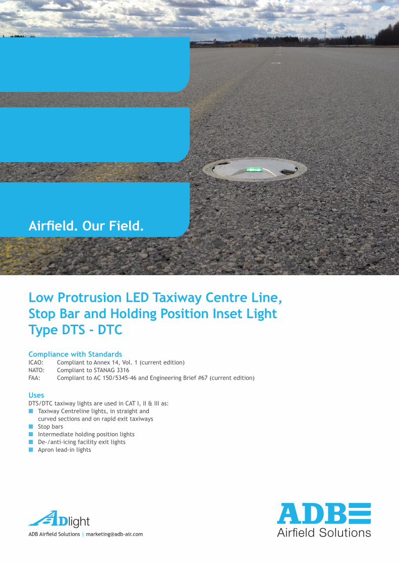
Low Protrusion LED Taxiway Centre Line, Stop Bar and Holding Position Inset LightType DTS - DTC
Compliance with StandardsICAO: Compliant to Annex 14, Vol. 1 (current edition)NATO: Compliant to STANAG 3316FAA: Compliant to AC 150/5345-46 and Engineering Brief #67 (current edition)
UsesDTS/DTC taxiway lights are used in CAT I, II & III as:■■ Taxiway Centreline lights, in straight and
curved sections and on rapid exit taxiways■■ Stop bars■■ Intermediate holding position lights■■ De-/anti-icing facility exit lights■■ Apron lead-in lights

The DTS and DTC lights are part of a complete range of LED inset lights, featuring innovative characteristics, as a leverage for:
Reliability■■ Additional watertightness barriers, protecting both the electronics and the LEDs in case of accidental water ingress,
along the prism or the gaskets as well as along the cables. ■■ Prisms of small dimensions, installed in a deep optical channel: optimal protection against rubber deposit, scratches
and shocks.
Modularity■■ High commonality of components between the various models. Stock management is easier■■ Field customisation according to the application is straightforward: a light can be transformed into another model by
swapping components.■■ Same tools and same procedures to maintain the whole range, reducing risks of mistake and losses of time.
Maintenance friendliness■■ Maintenance-friendly: components subject to wear or damage like prisms and cables can easily be replaced, without
opening the last watertightness barrier. Neither sealing compound nor resin is required.■■ Innovative design of the cable entry, permitting replacement without need to open the light.■■ Reduced number of components, for simplicity of the maintenance.■■ Pressure release plug for gas tightness testing of fixture after overhaul.
Low protrusion without negative slope■■ Limited height above pavement of 6.3 mm, reducing damages during winter operations or by towbarless tugs.■■ Despite the low protrusion, no part of the prism is below ground level, avoiding
loss of photometry during rainfall and sedimentation on the bottom of the prism
Optional scratch-resistant prismsOptionally, a higher hardness protective layer can be applied to the prism, making it much more resistant against scratches and sand-blasting.
FinishEnvironment-friendly, precision-cast aluminium alloy upper, intermediate and inner covers. Passivated, plain stainless steel hardware.
Electrical Supply6.6 A through one or two series transformer(s) (cat. leaflet A.06.110). DTS-DTC lights have been designed to work with any IEC or FAA compliant transformer. Transformer may be over-dimensioned without affecting the performances or the life-time of the light or the transformer. However, use of a non-matched transformer will reduce its efficiency.
DTS and DTC lights are LED lights from ADB...
They present all the advantages you might expect from an ADB LED inset light:■■ The evolution of the most successful LED lights in the world, fully adapted to the characteristics of the LED lighting
sources.■■ Very low energy consumption (typically 12W per side, compared to 40W for tungsten halogen lights).■■ Extremely reduced maintenance: calculated MTBF of 56,000 hours at 6.6A.■■ Increased traffic efficiency and availability of the taxiways thanks to the reduction of maintenance.■■ Optimum and homogenous light distribution along the lights installed on the same taxiway.■■ High discrimination between functions thanks to the saturated colours, their stability at the different brightness steps
and under all viewing angles.■■ Full compatibility with the classic airfield lighting series circuits. No need to
replace the CCR’s, series transformers, cables.■■ Installation on the same bases as F-range or TLP lights, for a straightforward
replacement.■■ Fully dimmable lights, respecting the response curve of traditional halogen
lights.■■ Substantial investment reduction for new installations, resulting from a lower
installed load.■■ Very low working temperature, ensuring a longer life of the components.■■ Highly efficient protection against lightning strikes, proven in laboratory and in
the field.■■ When turned on, light rise time is low. The light is perfectly adapted for any incursion protection system.■■ Optional monitoring function of the individual light source. In case of a defect, the LED light automatically disconnects
from the secondary side of the lamp transformer, resulting in an open circuit condition.
...they are also part of the familylight
Fig. 3: Low protrusion DTC G/Y
Fig. 2: Low protrusion DTS G/G
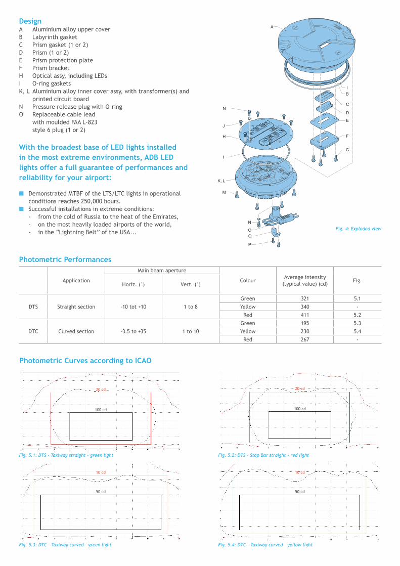
Application
Main beam aperture
ColourAverage intensity
(typical value) (cd)Fig.
Horiz. (°) Vert. (°)
DTS Straight section -10 tot +10 1 to 8
Green 321 5.1
Yellow 340 -
Red 411 5.2
DTC Curved section -3.5 to +35 1 to 10
Green 195 5.3
Yellow 230 5.4
Red 267 -
Photometric Performances
DesignA Aluminium alloy upper coverB Labyrinth gasketC Prism gasket (1 or 2)D Prism (1 or 2)E Prism protection plateF Prism bracketH Optical assy, including LEDsI O-ring gasketsK, L Aluminium alloy inner cover assy, with transformer(s) and
printed circuit boardN Pressure release plug with O-ringO Replaceable cable lead
with moulded FAA L-823 style 6 plug (1 or 2)
With the broadest base of LED lights installed in the most extreme environments, ADB LED lights offer a full guarantee of performances and reliability for your airport:
■■ Demonstrated MTBF of the LTS/LTC lights in operational conditions reaches 250,000 hours.
■■ Successful installations in extreme conditions: - from the cold of Russia to the heat of the Emirates, - on the most heavily loaded airports of the world, - in the “Lightning Belt” of the USA...
Photometric Curves according to ICAO
Fig. 5.1: DTS - Taxiway straight - green light
Fig. 5.3: DTC - Taxiway curved - green light
Fig. 5.2: DTS - Stop Bar straight - red light
Fig. 5.4: DTC - Taxiway curved - yellow light
100 cd
50 cd
100 cd
50 cd
20 cd
10 cd
20 cd
10 cd
G
BI
C
D
F
E
H
J
N
I
K, L
M
P
QO
A
NFig. 4: Exploded view

2) On a FAA L-868B size B steel base (fig. 7). The 8” dia light is mounted in an 8” to
12” dia. adapter ring bolted on the base. The bases are interconnected by means of conduits protecting the cables. The series transformer is installed under the light or better, in a separate pit. See catalogue leaflet A.05.120.
For detailed information, please refer to the mounting instructions supplied with the bases and the fittings.ADB technical team is at the disposal of users and contractors to provide guidance and advice in order to help solving any particular installation problem.
Fig. 6: Installation on 8” shallow base
Fig. 7: Installation on FAA L-868 base
1) On a shallow base (fig. 6). The 8” dia. base is secured in the pavement
by means of resin. Correct positioning and leveling are obtained
with a jig with sighting telescope. Wires between the light and the series transformer are installed either in saw cuts in the pavement filled with resin or in pipes in the lower concrete layers. Mounting on existing or new, larger diameter bases, is made possible by means of dedicated adapter rings.
Installation
Installation and outline dimensions (mm)
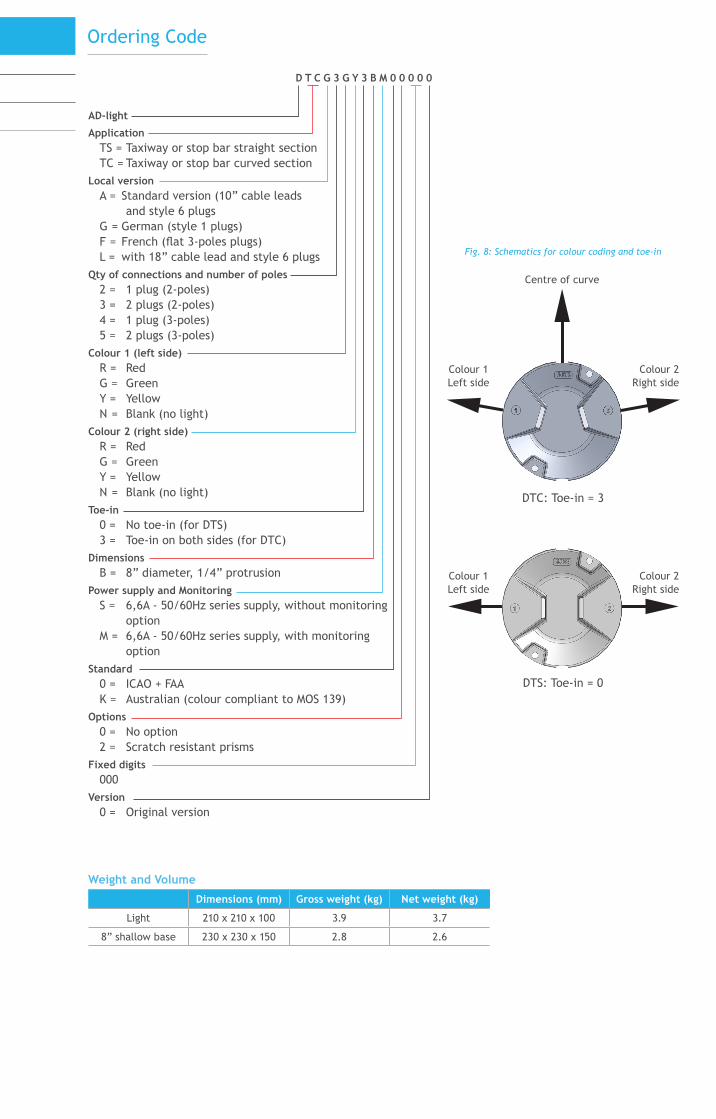
Weight and Volume
Dimensions (mm) Gross weight (kg) Net weight (kg)
Light 210 x 210 x 100 3.9 3.7
8” shallow base 230 x 230 x 150 2.8 2.6
Colour 1Left side
Colour 2Right side
Fig. 8: Schematics for colour coding and toe-in
DTS: Toe-in = 0
Ordering Code
Centre of curve
Colour 1Left side
Colour 2Right side
DTC: Toe-in = 3
AD-light
ApplicationTS = Taxiway or stop bar straight sectionTC = Taxiway or stop bar curved section
Local versionA = Standard version (10” cable leads
and style 6 plugsG = German (style 1 plugs)F = French (flat 3-poles plugs)L = with 18” cable lead and style 6 plugs
Qty of connections and number of poles2 = 1 plug (2-poles)3 = 2 plugs (2-poles)4 = 1 plug (3-poles)5 = 2 plugs (3-poles)
Colour 1 (left side)R = RedG = GreenY = YellowN = Blank (no light)
Colour 2 (right side)R = RedG = GreenY = YellowN = Blank (no light)
Toe-in0 = No toe-in (for DTS)3 = Toe-in on both sides (for DTC)
DimensionsB = 8” diameter, 1/4” protrusion
Power supply and MonitoringS = 6,6A - 50/60Hz series supply, without monitoring
optionM = 6,6A - 50/60Hz series supply, with monitoring
optionStandard
0 = ICAO + FAAK = Australian (colour compliant to MOS 139)
Options0 = No option2 = Scratch resistant prisms
Fixed digits000
Version0 = Original version
D T C G 3 G Y 3 B M 0 0 0 0 0
Suggested Specification
The LED taxiway centre line, stop bar and holding position light shall have an outer diameter of 203mm. The protrusion above the surrounding pavement shall not exceed 6.3 mm. The light shall resist all stresses imposed by impact, rollover and static loads of present day aircraft without damage to the light or aircraft or vehicle tires.
The hardened transparent optical grade glass prisms shall be mechanically fastened in the cover, using clamp and gasket for the watertightness. They shall be user-replaceable without need to apply sealing compound.No optical adjustment shall be required after replacement of LED assembly or glass prism. There will be no negative slope in front of the prism (s).
In order to reduce the prism dimensions, there shall be a maximum of 3 LEDs per side.
The power supply cable(s) shall be made of two separate heat resistant wires, equipped with an FAA L-823 plug for connection. The cable(s) shall be user-replaceable without the need to open the light.
Additional watertightness barriers shall be provided to protect the active parts of the light against accidental water entries along the prism and along the input cable. Those barriers shall protect the power adapter, the LEDs and all internal connectors.
A reusable threaded plug shall allow for control of the watertightness of the light.
The hardware shall be plain stainless steel throughout.All components shall be corrosion proof without using environment aggressive protective coatings.
Power consumption shall not be higher than 12 W per light beam, with a minimum power factor of 0.9 at 6.6A.The lights shall work satisfactorily when powered through an isolation transformer complying with FAA AC 150/5345-47 from any type of Constant Current Regulator (CCR) complying with FAA AC 150/5345-10 and IEC 61822.The light shall be able to sustain currents up to8.25A RMS without failure, with a maximum crest factor of 3.2 for limited periods.MTBF of the complete light, calculated at full intensity and for a pavement temperature of 70°C, shall be at least 56,000 hours.
The light characteristics shall be in compliance with the requirements of ICAO Annex 14, Appendix 2, fig. A2-12, A2-13 or A2-14.
The variation of the light output in function of the input current shall match that of a halogen light. No “steps” in the light output shall be visible when the current is increased progressively.For currents higher than 6.6A, the light output shall remain stable at the same value as at 6.6A.
Specifically, it shall comply with FAA Engineering Brief N° 67.
Colour coordinates for the 5 points of the primary beam shall comply with ICAO Annex14, Appendix 1, § 2. There shall be no modification of the colour when the light is powered at reduced intensity or viewed from various angles.
To limit the number of spare parts and to simplify the maintenance procedures, preference shall be given to equipment with a high number of components that are common to the same family of inset lighting fixtures.
ww
w.c
omit
h.be
© ADBall rights reserved
order number DOCA04520EV1subject to modifications
ADB Airfield Solutions Leuvensesteenweg 585 B-1930 Zaventem Belgium
Phone: +32 (0)2 722 17 11 Fax: +32 (0)2 722 17 [email protected]