lolipem long-life pem-f h &hp systems at ... · tel: ++48 (12) 628 26 60; e-mails:...
TRANSCRIPT

Project acronym: LOLIPEM website address: www.lolipem.eu
title: Long-life PEM-FCH &CHP systems at temperatures ≥100°C
Funding Scheme: Fuel Cells and Hydrogen Joint Undertaking (FCH JU)
Funding board: EC (FP7) and FCH JU
Starting date: January 1st, 2010
Duration: 36 months
Date of latest version of Annex against which the assessment is made: February 2012
Deliverable number: D 4.9
Deliverable: “Final plan of use and dissemination of foreground knowledge”
Contractual deliver date: M36, December 2012
Responsible: PartnerP8 Krakow University of Technology
Tel: ++48 (12) 628 26 60; e-mails: mailto:[email protected]; [email protected];
Authors: Jarosław OSIADACZ, Bogna GROCHOLA and Dawid GACEK
DISSEMINATION LEVEL
PU Public X
PP Restricted to other project participants (including the Commission Services)
CO Confidential, only for members of the consortium (including the Commission Services)
GA N° 245339 Deliverable D4.9
Page 2
TABLE OF CONTENTS:
ABBREVIATIONS ........................................................................................................ 3
1. INTRODUCTION .......................................................................................... 4
2. THE LoLIPEM PROJECT: ASSUMPTIONS, METHODOLOGY & RESULTS........ 6
2.1. Introduction / Assumptions .......................................................................................................... 6
2.2. Project objectives .......................................................................................................................... 8
2.3. Methodology and materials .......................................................................................................... 9
2.4. Experimental setup and measurement principles ..................................................................... 11
2.4.1. Test bench for long term durability measurements and advanced control strategies ............ 21
2.4.2. Durability measurements ........................................................................................................... 26
2.5. Results .......................................................................................................................................... 34
3. DISSEMINATION OF KNOWLEDGE ............................................................ 35
3.1. Introduction ................................................................................................................................. 35
3.2. Dissemination strategy ............................................................................................................... 35
3.3. Dissemination actions – activities undertaken .......................................................................... 36
3.3.1. Project Website ....................................................................................................................... 36
3.3.2. Events ...................................................................................................................................... 37
3.3.3. Researchers exchanges between partners ............................................................................ 38
3.3.4. Publications related to the project results............................................................................. 39
3.3.5. Summary ................................................................................................................................. 49
3.4. Dissemination actions – plans for the future ............................................................................. 50
4. STRATEGY OF EXPLOITATION ................................................................... 51
4.1. Introduction ................................................................................................................................. 51
4.2. Exploitation actions ..................................................................................................................... 58
GA N° 245339 Deliverable D4.9
Page 3
ABBREVIATIONS
APU Auxiliary Power Units
CHP Combined Heat Power
FC Fuel Cell
FCH Fuel Cell Hydrogen
GDE Gas Diffusion Electrode
GDL Gas Diffusion Layer
MEA Membrane Electrode Assembly
MPL Microporous Diffusion Layer
PEEK Poly-Ether-Ether-Ketone
PEMFCH Polymeric Electrolyte Membrane FCH (also Proton Exchange Membrane FCH)
PES Poly-Ether-Sulfone
PFSA Perfluoro Sulfonic Acid
PPSU Poly-Phenyl-Sulfone
PTFE Polytetrafluoro Ethylene
RH Relative Humidity
SAP Sulfonic Aromatic Polymer
SPG Stationary Power Generation

GA N° 245339 Deliverable D4.9
Page 4
1. INTRODUCTION
“Plan for the Use and Dissemination of the Foreground (PUDF)” as a contractual Deliverable is an important
document summarizing the consortium’s strategy and concrete actions to protect, disseminate and exploit
the foreground generated by a project.
The “preliminary” PUDF was presented to the EC in the actual project proposal itself (in the Part B
Application, then in “Description of Work”). During the implementation of the project, the project team
reported periodically to the Commission on any activities carried out in relation to the PUDF.
At the moment - the “final PUDF” (Deliverable 4.9.) is presented at the end of the project and describes
detailed plans for the management of foreground, which enables the EC to evaluate the success of a
project1.
The PUDF clearly outlines convincing plans and intentions of the research consortium to use and
disseminate the project results. The plan is divided into two sections:
A section related to the publishable results and to the corresponding dissemination activities. This
section, which is public, summarizes:
o how participants plan to reach their target public,
o the communication strategy,
o a specific set of dissemination actions presented in a verifiable way to ensure that the EC can
keep track of them.
A section that describes exploitable results and related activities, which remain confidential, at least
until protection and economic exploitation of the results have been implemented. This section, which is
partly confidential, includes:
o verifiable list of all intellectual property rights that have been applied for or registered (e.g., a
European patent has been applied for);
o a list of all the results that may have commercial or industrial applications (e.g. software,
inventions, prototypes, compiled information and data, etc.);
o an outline of the owner of each particular element of foreground, whether it is a single
participant or several of them (in a situation of joint ownership);
o an explanation of how the foreground has been or is going to be used, in either further
research or commercial exploitation activities, including elements such as the following:
purpose, main features and benefits of each technology or product, derived from the
research results: innovative aspects in comparison with technologies and products
already available, needs for further R&D activity (and implied risks), collaboration
needs for exploitation (technology transfer activities);
customer detection: identification of the potential customers and the factors that
affect their purchasing decisions;
features of the target market: size, growth rate, share that the
1 “Make Research Work for Your Company - Strategic Guide to Successfull Use and Disseminiation of the Research anfd the Development Project”. The Guide has been produced as part of Coordination and Support Activities being carried in the “USEandDIFFUSE” Project (Support of dissemination and exploitation of results obtained in research projects realized with the participation of the SME sector), that is funded under the European Commission’s 7th Framework Programme (FP7), and more specifically under “Research for the Benefit of SMEs”. Cracow University of Technology (CUT) was a project partner responsible for preparation of the Guide.

GA N° 245339 Deliverable D4.9
Page 5
technology/product.could reach, driving factors likely to change the market, legal,
technical and commercial barriers, other technologies likely to emerge in the near
future;
positioning: how the participant (or other entity) entitled to the technology
exploitation is positioned (or should be positioned) in the market, competing
businesses/applications/technologies.
Figure 1: General strategy of Use and Dissemination of Foreground. Exploitation is made after the
timeframes of the project.
All project partners have signed a Consortium Agreement before the start of the project, setting the
principles of the consortium management and placing the relationship between the partners and their
responsibilities on a legal basis for the duration of the work. In particular, the agreement includes
specific arrangements concerning intellectual property rights to be applied among the participants and
their affiliates, in compliance with the general arrangements stipulated in the contract. It thus specifies
the rules for dissemination and use (confidentiality, ownership of results, patent rights, exploitation of
results, protection and dissemination of knowledge), as well as financial and legal provisions.
Consortium Agreement, Grant Agreement and FP7 general rules are a base for dissemination activities
and professional (incl. commercial) use of the results (see Chapter 4.1., as well).

GA N° 245339 Deliverable D4.9
Page 6
2. THE LoLIPEM PROJECT: ASSUMPTIONS, METHODOLOGY & RESULTS
2.1. Introduction / Assumptions
Previously developed stationary power generation & combined heat and power systems (SPG&CHP) based
on fuel cells can use different types of fuel cell (FC). Depending on FC type they represent different
temperature of operation: 70-80 °C for Polymeric Electrolyte Membranes FC, 150-190 °C for
Polybenzoimidazole-Phosphoric Acid FC, 400-600 °C for Molten Carbonates FC, and 600-1.000 °C for
Ceramic Oxide FC.
The LoLiPEM project was aimed to perform advanced R&D of SPG&CHP systems based on Polymeric
Electrolyte Membrane FC Hydrogen (PEMFCH). PEMFC technology is used in a range of application
segments, for instance in transport and stationary applications, and has a power range up to hundreds of
kilowatts. Therefore PEMFC has dominated the shipments by megawatt since 2008.
Project idea was based on the foreseen assumptions that the SPG&CHP systems based on FCs can help
reducing pollution, especially in large towns. As it was underlined in the project proposal expected results
are intended to be useful for reducing the petrol dependence and for reducing CO2 emissions in the
atmosphere. Finally, utility of the project results in the case of electrical black out could be also considered.
Mentioned co-generation systems based on PEMFCHs are of great interest because they can use very thin
and flexible ionomer membranes exhibiting high proton conductivity at relatively low temperature without
any addition of mineral acids. The peculiar characteristics of the ionomer membranes make easier the
development of small co-generation systems very suitable for small buildings and for mobile (automotive)
applications. The absence of free acids in the membranes avoids lowering of conductivity due to its loss and
poisoning of electrode catalysts. Furthermore, their low operating temperature reduces insulating and
corrosion problems as well as risks for their management. Finally, being noiseless, very small systems could
be provided even for single flats if an easier management is developed.
The proton exchange membrane fuel cell (PEMFC) uses a water-based, acidic polymer membrane as its
electrolyte, with platinum-based electrodes. PEMFC cells operate at relatively low temperatures (below 100
degrees Celsius) and can tailor electrical output to meet dynamic power requirements. Due to the relatively
low operating temperatures and the use of precious metal-based electrodes, these cells must operate on
pure hydrogen. PEMFCs are currently the leading technology for light duty vehicles and materials handling
vehicles, and to a lesser extent for stationary and other applications.
Hydrogen fuel is processed at the anode where electrons are separated from protons on the surface of a
platinum-based catalyst. The protons pass through the membrane to the cathode side of the cell while the
electrons travel in an external circuit, generating the electrical output of the cell. On the cathode side,
another precious metal electrode combines the protons and electrons with oxygen to produce water,
which is expelled as the only waste product; oxygen can be provided in a purified form, or extracted at the
electrode directly from the air.

GA N° 245339 Deliverable D4.9
Page 7
Chemical Equation:
Anode: 2H2 → 4H+ + 4e-
Cathode: O2 + 4H+ + 4e- → 2H2O
Figure 2: General scheme of PEMFC2
A variant of the PEMFC which operates at elevated temperatures is known as the high temperature PEMFC
(HT PEMFC). By changing the electrolyte from being water-based to a mineral acid-based system, HT
PEMFCs can operate in 120°C (the limes of 200°C is expected to be achievable in the nearest future)3. This
overcomes some of the current limitations with regard to fuel purity with HT PEMFCs able to process
reformate containing small quantities of Carbon Monoxide (CO). The balance of plant can also be simplified
through elimination of the humidifier.
HT PEMFCs are not superior to low temperature PEMFCs; both technologies find niches in where their
benefits are preferable. The table below summarises differences between the two PEMFC variants:
Table 1. Main differences between Low- and High-temperature PEMFC4
Parameters Low Temp. PEMFC High Temp. PEMFC
Operating temperature 70-80 (up to 90)°C 100-120 (up to 200)°C
Electrolyte Water-based Mineral acid-based
Pt loading 0.2-0.8 mg/cm2 1.0-2.0 mg/cm2
CO tolerance <10 ppm 1 - 5 % volume
Other impurity tolerance Low Higher
Power density Higher Lower
Cold start? Yes No
Water management Complex None
Data compiled by the US Department of Energy demonstrate that platinum loading on PEMFC has
decreased by more than 80% between 2005 and 20105 and further reduction reductions in platinum
loadings for fuel cell catalysts are foreseen by 2015. It is widely expected that these targets are feasible,
2 The ”Fuel Cell Today” Industry Review 2011 3 Article “FCT - Fuel Cell Technologies – PEMFC” , www.fuelcelltoday.com, page visited IX’2011 4 ibidiem 5 The ”Fuel Cell Today” Industry Review 2011

GA N° 245339 Deliverable D4.9
Page 8
and “Fuel Cell Today”6 believes they are essential to achieving the necessary cost reductions to enable the
widespread use of fuel cells in both new and existing applications. However, in PEMFC, DMFC and PAFC,
platinum offers superior performance compared to other catalyst materials in terms of the balance
between power density, durability, activity and cost, and is unlikely to be fully removed from fuel cells for
these reasons.
A variant of PEMFC which operates at higher temperatures is emerging in the stationary sector where it is
finding application in both micro-CHP and UPS. Running at temperatures over 100°C HT PEMFC use
different materials, such as polybenzimidazole, in their membranes and are more tolerant to impurities in
the fuel streams. When fuelled by methane or other hydrocarbons, the higher stack operating temperature
means the stack is more tolerant to the impurity carbon monoxide in the reformed fuel. As a result, the fuel
processing system can be much simpler. The additional by-product heat produced by HT PEMFC can also be
used as part of an integrated installation, increasing the overall efficiency of these units.
The negative aspect of these systems was that the operating temperature of state-of-the-art PEMFCHs (70-
80°C) is too low for efficient cogeneration7. It is well known that the temperature of the cooling fluid in co-
generation systems must be preferably ≥100°C. Such high temperature facilitates both the warm water
distribution in the buildings and renders an additional heating of the water unnecessary otherwise
requested by the temperature-air conditioner systems. Furthermore, the higher temperature decreases the
anode poisoning due to small amounts of carbon monoxide, always present in the hydrogen obtained by
reforming processes, and improves the fuel oxidation kinetics leading to an enhancement of fuel cell
efficiency. Thus, an enhancement of at least 20-30°C of the state-of-the-art operating temperature of
PEMFCHs is highly desirable and it could be decisive for the development of SPG&CHP systems based on
PEMFCHs.
In this type of co-generators, the operating temperature limits are essentially due to the decay of
performance of the PEMs used. A decay of the conductivity of the ionomer used in the catalytic electrodes
can lead to a decrease of the cell performance.
Detailed information & discussion is reported in the section “Progress beyond the-state-of-art” of the
Project Proposal Annex I -”Description of Work”.
2.2. Project objectives
The main objective of the LOLIPEM project has been the development of a long-life SPG&CHP systems
based on PEMFCHs operating at temperatures greater than 100°C. In order to reach this main objective,
various sub-objectives of the project have been identified:
Development of new stable Perfluoro Sulfonic Acid (PFSA) membranes operating at least 20°C
higher than that of the state-of-the-art and fulfilling the requirements in terms of long term
durability for stationary fuel cell operation.
6 ibidiem 7 This is not the only inconvenience. The activation losses are lower at high temperature and the tolerance of contaminants increases!

GA N° 245339 Deliverable D4.9
Page 9
Development of new stable non perfluorinated ionomers, such as sulfonated aromatic polymers
(SAPs), much less expensive than PFSA and exhibiting a lifetime comparable to that of modified
PFSA membranes, in order to reduce the cost of the co-generation systems, investigating
innovative thermal and chemical treatments for promoting the cross-linking reactions between
adjacent ionomer chains.
Development of new catalytic electrodes more stable at the operating temperatures that have
been used in MEA.
Preparation and texting of MEAs based on these innovative materials.
Reducing the cost of the high temperature FCH by facilitating the replacement of MEAs (“use and
discard” MEAs).
Establishment of accelerated test techniques and lifetime prediction methods for MEAs testing.
Development of a procedure for “post mortem” analysis on MEAs, to identify the main parameters
and conditions affecting the MEA performance and durability.
Development of a prototype of a Modular multi-PEMFCHs system for Combined Heat and Power
(MoPEM) based on Polymer Electrolyte Membrane Hydrogen FC (PEMFCH) for facilitating the
replacement of the single PEMFCH and hence the MEA.
Exploitation of the results in terms of patents for the industrial partners, publications in high impact
international journals and top international conferences, reaching out to the public and increasing
the awareness of this technology.
2.3. Methodology and materials
These main areas of innovation were foreseen for the LoLIPEM project:
Novel polymer membranes. Research focused on the development of a membrane with sufficient proton
conductivity in order to allow huge system simplification and, in consequence, a significant reduction in
cost of manufacturing.
The primary task was to develop proton exchange membranes able to operate in the temperature
range up to 130 °C, at high relative humidity, and without any degradation. The innovative and cutting-edge
approaches included both the improvement of existing systems by new processing methods, and the
development of new polymers.
The new polymers and membranes were characterised for all properties of relevance to fuel cell
application, and preliminary, screening level, in situ single fuel cell tests were performed. URoma2
advanced in existing perfluorosulfonic polymer technologies by modification of the existing Nafion
ionomer; new polymers new compositions and new processing methods were used in the fabrication of
new composition perfluorosulfonic, sulfonated polyaromatic membranes; membranes were developed and
the ionomer were also supplied for application in the catalyst layer.
Catalyst and MEAs. Project developed novel catalyst materials that are capable of stable performance at
the higher operating temperatures afforded by the new membrane developments and to measure and
identify the optimum kinetic performance from the interaction of the catalysts and electrolytes. This has
required materials development, study of high temperature decay processes and kinetic studies of
catalyst/ionomer interactions.

GA N° 245339 Deliverable D4.9
Page 10
MEA preparation
The MEA preparation was the key-step in the preparation of a fuel cell system with high performance and
life-time. In this step the PEM and the GDEs were brought together in order to form the MEA being itself
the centre piece of the fuel cell. The developed MEA preparation process included two steps. The first step
was dedicated to the preparation of the catalytically active GDEs, these were assembled in an additional
hot-pressing step with the proton conducting membrane in order to form the MEA.
GDE preparation
In this project we focused on the preparation of 50 cm² GDEs, starting from commercial available GDLs
(Torray). The therefore used process implies the following steps:
(a) ink preparation and its coating on the GDL via spiral blade,
(b) impregnation with SPEEK solution (only for MPL Type 2)
(c) impregnation with Pt precursor followed by its electrochemical deposition
(d) leaching of the GDE.
For the preparation of SPEEK containing inks (MPL Type 1) a dispersion consisting of PTFE, high surface
carbon support and SPEEK was ultrasonicated under vigorously stirring. The so prepared ink was
homogeneously coated onto the GDL using a spiral blade process. After evaporation of the remaining
solvents the sample was allowed to cool down to room temperature before the further utilization. In 3a &
3b a representative MPL Type 1 is shown.
SPEEK free inks (MPL Type 2) were prepared analogously, but in contrast to the latter method, SPEEK
solution was not introduced directly in the ink but was added via an additional step after coating of the GDL
with a MPL consisting of the high surface are carbon support and the PTFE. In this case PTFE sintering was
achieved by heating the coated GDL at 220°C, 280°C and 360°C. The ionomer solution was brought then
into the carbon/PTFE layer using dip-coating technique. Elimination of residual solvent was achieved, at
room temperature over desiccant under vacuum [8]
Nafion® containing inks (MPL Type N) were prepared by the method described in our paper [9]. The
method basically consists of dispersing the ionomer solution and the carbon black in an appropriate
dispersion agent by the use of an ultra-sonic bath. The resulting precursor ink was coated onto a GDL by
using an airbrush, inkjet or a coating-knife. Typical compositions of PFSA – and SPEEK-consisting CLs are
summarized in Table 22.
Table 2: Typical dry composition of PFSA- or SPEEK containing CLs.
PFSA ink SPEEK ink
compound wt.% compound wt.%
C 55 C 75
Nafion 35 SPEEK 15
PTFE 10 PTFE 10
8 F. Arena, J. Mitzel, R. Hempelmann, Zeitschrift für Physikalische Chemie 2013 9 J. Mitzel, F. Arena, H. Natter, T. Walter, M. Batzer, M. Stefener, R. Hempelmann, International Journal of Hydrogen Energy 2012, 37, 6261-6267.

GA N° 245339 Deliverable D4.9
Page 11
Figure 3: SEM images of the prepared MPL Type 1, a) with a 100-fold magnification and b) with a 1900-
fold magnification.
The Pt precursor (solution of hexachloroplatinic acid) was brought into the so prepared MPLs by means of
dip-coating. To avoid hygroscopically induced migration of the Pt ions after immobilization in the MPL, all
samples were stored over desiccant under vacuum. The GDL including MPL and Pt precursor, arranged as
cathode, was pressed in a fuel cell like setup onto a half MEA consisting of Nafion® 115 and a commercial
Johnson Matthey GDE acting as hydrogen depolarized anode (HDA). During the electrodeposition, the HDA
was fed with hydrogen and serves thus simultaneously as dynamic hydrogen electrode. The cathode side
was purged with nitrogen. The technique implies furthermore the use of a potentiostatic double pulse.
Further experimental details concerning the pulsed potentiostatic electrodeposition for precursor
reduction by a HDA have been described previously. Activation of the Pt surface as well as removing of non-
reduced Pt precursor was realized by several purification steps after catalyst deposition. For this purpose
the GDE was immersed alternately in diluted sulfuric acid and deionized water at room temperature. The so
prepared GDEs were used as gas diffusion anode as well as cathode. For all prepared MEAs a Nafion-based
ELE0162 GDE from Johnson Matthey was used for the counter side.
2.4. Experimental setup and measurement principles
The aim of project was to provide a down-selection of materials for a more focused practical electrode and
MEA design using a selected set of new ionomers, electrolytes and catalysts as well. It delivered newly
developed and improved catalysts for high temperature operation.
Moreover, it was required to develop and elaborate new membrane electrode assemblies
(including membrane and catalyst layer) suitable for high temperature operation and demonstrate and
evaluate such membranes in a fuel cell stack. The selection of the materials has been done also on the basis
of new protocols of materials preparation and properties measurements developed to make the selection
more reliable.
Mass transport properties evaluation
Among the various characterization of the membrane one of the main important in the evaluation of mass
transport properties to correctly estimate the proton conductivity of the membrane but also its permeance
that, in other terms, represents a measure of the cross over phenomena that can occur in the PEMFC.

GA N° 245339 Deliverable D4.9
Page 12
Within LOLIPEM project a new approach for the systematic evaluation of the mass transport
properties of a PEM was proposed. A protocol for permeation measurements has been elaborated to
rightly compare the transport properties of different membranes as a function of the same operating
conditions due to the strict dependence of the membrane performance on the relative humidity (RH) and
temperature. The method has been proven on various membranes developed during the research activity
by the various partners.
The proton conductivity represents the other transport property of the membrane was considered
together with the gas permeation properties. The ideal/desired membrane had to exhibit low gas
permeability and high proton conductivity. Thus, a new parameter called Transport Performance Index has
been defined as the ratio of hydrogen permeability and proton conductivity. This leads to an immediate
idea of the whole mass transport performance of the membrane. The mass transport properties, proton
conductivity and Transport Performance Index were measured for the various membranes as function of
temperature, pressure, relative humidity feeding different gaseous streams.
The elaborated protocol took into account the strict dependence of the membrane performance on
the RH and temperature. The mass transport measurements (permeation tests) started feeding H2 at 80°C
and RH=50%. Then hydrogen was replaced by N2 keeping the same temperature and RH. Afterwards,
nitrogen was replaced by O2, always at 80°C and RH=50%. An analogous sequence (H2, N2, O2) was repeated
once for higher RH (75%) and again for RH=100%, at the same temperature. A total of nine steps complete
this first part. The same sequences were repeated at the higher temperature values of 100°C and 120°C.
The experiments were performed continuously and the membrane was left overnight under a gaseous
stream at 2 bar. Figure 4 shows more about the specific sequence and combination of these variables. The
use of this protocol in the testing of the various membrane samples significantly contributed in the
evaluation of the membrane performance and, thus, on its suitability for further use in MEA.
H2 N2 O2
O2 N2 H2
H2 N2 O2
N2 H2 O2
O2 N2 H2
H2 N2 O2
N2 H2 O2
O2 N2 H2
H2 N2 O2
RH=50%
RH=50%
RH=50%RH=75%
RH=75%
RH=75%
RH=100%
RH=100%
RH=100%
80°C
100°C
120°C
1 1918171615141312111098765432 26252423222120 27
STEPS
TEM
PER
ATU
RE,
°C
80
100
120
140
Figure 4. Mass transport measurements – Experimental procedure.

GA N° 245339 Deliverable D4.9
Page 13
Hot-Pressing
GDEs and proton conducting membrane were assembled in an additional step to form the MEA. For this
purpose a hot-pressing step was used to assure good contact between GDE and PEM and therefore to
maximize the “3-phase zone”. Figure 5 shows a typical cross-section of hot-pressed MEA. From the image
typical MPL thicknesses of 18-25 µm were revealed.
Table 33 summarizes the optimized hot-pressing parameter (temperature, pressure and time)
depending the used PEM. Where T represents the hot-pressing temperature, p the corresponding pressure,
t the time and CR the cooling rate. In the case of a slow cooling rate (SCR) MEA is cooled down to room
temperature with approximately 1 °C min-1. Whereas in the case of a fast cooling rate (FCR) the MEA is
allowed to cool down from 125°C to room temperature within 3 min.
Table 3: Optimized hot-pressing parameter for Nafion® and cross-linked SPEEK (XL-SPEEK).
Parameter Nafion® SPEEK
T / °C 125 160-190
p / kNcm-2 0.5 0.5
t / s 300 300
CR FCR SCR
Figure 5: Cross-sectional SEM image of Nafion 212 membrane with SPEEK containing GDEs.
MEA development
The use of alternative PEMs materials necessitate apart from the development of appropriate GDEs also
the development of the MEA in order to satisfy high life-time in addition to competitive performance. In
order to assembly MEAs possessing cross-linked SPEEK as centrepiece life-time and performance relevant
factors like hot-pressing parameters, MEA pre-conditioning and performance testing are screened and
optimized.
Hot-pressing temperature
Interfacial contact between the SPEEK material and the GDEs was improved using a hot-
pressing temperature close to the glass transition point of the used membrane. Corresponding
measurements revealing the change of the glass transition temperature Tg with depending on the

GA N° 245339 Deliverable D4.9
Page 14
SPEEK membranes of cross-linking degree were performed by Prof. P. Knauth (University of Aix-
Marseille).
The influence of the MEA hot-pressing temperature was therefore investigated in the range of 160°C to
250°C. For all prepared MEA a cross-linked SPEEK membrane (thickness: 30 µm, provided by Fumatech &
URoma2) and commercial GDEs from Johnson Matthey are used. Figure 6 and Table 44 revealed that best
results in terms of fuel cell performance abd MEA life-time were obtained using a hot-pressing temperature
in-between 160°C and 190°C respectively.
Table 4: Summarizing table for MEA performance and life-time as function
of the applied hot-pressing temperature.
Hot-pressing EOL j-peak @ 650 mV
C h A cm-2
160 25 1.1
190 > 4.5 1.0
220 26 0.8
250 1.5 0.04
Figure 6: Polarization curves at 80°C for MEAs prepared
using different hot-pressing temperatures.
Variation of heating and cooling rate during hot-pressing
Cross-linked SPEEK being more brittle than PFSA material reacted more sensitive to the
applied mechanical stress introduced in the MEA by the hot-pressing step. Therefore different
heating and cooling rates were investigated in order to minimize the aforementioned. For this
purpose different MEAs based cross-linked SPEEK membrane (20 µm of thickness) were hot-
pressed with commercial GDEs from Johnson Matthey.
Figure 7 summarizes the results in terms of polarization curves for the variation of heating
and cooling rate by representing the last polarization cycle before the beginning of degradation.
From the plot the positive influence of using a slow heating as well as a slow cooling rate during the
hot-pressing can be deduced. This result is underpinned by the analysis of the MEA life-time
summarized in Table 55.
EX-330(180/7) hot-pressing @ 250°C
EX-330(180/7) hot-pressing @ 220°C
EX-330(180/7) hot-pressing @ 190°C
0,0 0,2 0,4 0,6 0,8 1,0 1,2 1,4
0,5
0,6
0,7
0,8
0,9
1,0
50 cm² / Tcell
= 80°C / RH = 95% / H2
= O2
= 1.2
vo
lta
ge
(V
)
current density (A/cm²)
EX-330(180/7) hot-pressing @ 160°C

GA N° 245339 Deliverable D4.9
Page 15
Figure 7: Polarization curves for the applied heating and cooling rates
during the hot-pressing process.
Table 5: Results in terms of fuel cell performance and MEA life-time investigating the influence of the used
heating and cooling rate during the hot-pressing process.
EOL j-peak @ 650 mV
h A cm-2
FH/FC 6.0 0.85
FH/SC 6.5 0.70
SH/SC 12.0 1.00
Cross-linking degree
A series of membranes differing in cross-linking conditions during their preparation process were
used to prepare MEAs. In all cases commercial Johnson Matthey GDEs were used.
SE detector
BSE detector
SH & SC
0.0 0.2 0.4 0.6 0.8 1.0 1.2 1.4
0.5
0.6
0.7
0.8
0.9
1.050cm² / T
cell= 80°C / RH = 95% /
H2= 1.1
O2= 1.2
volta
ge [V
]
current density [A/cm²]
FH & FC
FH & SC

GA N° 245339 Deliverable D4.9
Page 16
Figure 8. SEM analyses: not used (delaminated) MEA-EX 330.
Table 66 lists the membranes (thickness: 30 µm) used for these tests. They differ significantly in the
annealing temperature time (t2) correlated to the degree of cross-linking.
Figure 8. SEM analyses: not used (delaminated) MEA-EX 330.
Table 6: Summary of the prepared MEA based on an EX-330 membrane thermally annealed for different
times.
Name T2 t2 Supplier
°C h
EX-330 180-9 180 9 URoma2
EX-330 180-7 180 7 FUMATECH
EX-330 180-3 180 3 FUMATECH
EX-330 180-9
Figure 9 shows the time-dependent signals for current (black), voltage (blue), and OCP (red).
The representation clearly shows the initial increase of the MEA performance during the first 5 h of
operation followed by a decrease of both the maximum current and the OCP.
SE detector
BSE detector

GA N° 245339 Deliverable D4.9
Page 17
0 2 4 6 8 10 12 14 16 18 20 22 24
0
10
20
30
40
50
60
70
80
50 cm² / Tcell
= 80°C / RH = 95% / H2
= O2
= 1.2
current
voltage
OCP
time
cu
rre
nt (A
)
0,0
0,1
0,2
0,3
0,4
0,5
0,6
0,7
0,8
0,9
1,0
vo
lta
ge
(V
)
Figure 9: Graph showing the time-dependent signals
for current, voltage, OCP and Ohmic resistivity.
EX-330 180-7
Figure 10 represent the quasi-stationary polarization curves reached after 5, 15, and 5 h at
operation temperatures of 80°C, 90°C and 95°C respectively.
The loss in performance at 95°C is attributed to the notable dew point accompanied by high
water vapour partial pressure and resulting reactant starvation on the GDEs. Accordingly a
chronopotentiometric measurement at 95°C using a decreased RH (80%) was performed after a
total operation time of around 25 h. During this measurement a similar decrease of the OCP
concomitantly with a significant drop of performance was observed.
0.0 0.2 0.4 0.6 0.8 1.0 1.2 1.4
0.5
0.6
0.7
0.8
0.9
1.0
50 cm² / H2
= O2
= 1.2
volta
ge [V
]
current density [A/cm²]
EX-330 (180/7) @ 80°C / 95 % RH
EX-330 (180/7) @ 90°C / 95 % RH
EX-330 (180/7) @ 95°C / 95 % RH
Figure 10: Polarization curves of a MEA collected at 80°C, 90°C and 95°C.
EX-330 180-3
Best results in terms of fuel cell performance as well as mid-term stability were obtained
using a membrane with shortest thermal annealing time (3 h). The obtained polarization results for
80°C and 90°C are represented in Figure 11. In both cases the quasi-stationary curves are obtained
after 5 h (Tfc = 80°C) and after 7 h (Tfc = 90°C).

GA N° 245339 Deliverable D4.9
Page 18
0.0 0.2 0.4 0.6 0.8 1.0 1.2 1.4
0.5
0.6
0.7
0.8
0.9
1.0
50 cm² / H2
= O2
= 1.2
EX-330 (180/3) @ 80°C / 95 % RH
EX-330 (180/3) @ 90°C / 95 % RH
current density [A/cm²]
volta
ge [V
]
Figure 11: Polarization results for 80°C (brown) and 90°C (red).
Table 77 summarizes the results for the test in terms of fuel performance at 650 mV and as well as
mid-term stability using Tfc = 80°C and 95 % RH. Highest current densities were obtained for SPEEK
membranes with a thermal annealing time of 7 h and 3 h. Besides the performance increasing effect the
reduction of annealing time increases the MEA life-time.
Table 7: Characteristic values of fuel cell performance and life-time as function of thermal annealing time
for the used SPEEK EX-330 membrane.
EX-330 (180/9) EX-330 (180/7) EX-330 (180/3)
j at 650 mV / A cm-2 0.65* 1.1 1.1
EOL / h 8-10 25 - (> 39)
* no quasi-stationary conditions were reached during measurement
Influence of Reinforcing Frame and Pre-Conditioning Method
The border-region between GDE and SPEEK membrane was identified as “weak-point” and
therefore as possible source of mechanical failure. Hence the reinforcement of this region was
investigated in order to increase the MEA life-time. As additional parameter the type of the MEA
pre-conditioning was studied in the same set of experiments. In this context the liquid water pre-
conditioning and the chronopotentiometric pre-conditioning were analysed with regard to their
beneficial effect on the MEA performance and life-time. In all cases MEAs consisting of cross-linked
SPEEK membrane (30 µm of thickness) and JM GDEs were used.
Figure 12 summarizes the polarization curves obtained at 60°C and 80°C. Figure 12a clearly
shows that the use of a reinforcing frame in combination with a chronopotentiometric pre-
conditioning has the most beneficial effect on fuel cell performance. Unexpectedly the MEA pre-
conditioned with liquid water without any reinforcing frame offered good fuel cell performance
however featuring a very short life-time (cf. Table 8).
The obtained polarization curves at 80°C (cf. Figure 12b) confirmed the before mentioned
results. From 8 the life-time increasing effect of the used reinforcing frame is obvious.

GA N° 245339 Deliverable D4.9
Page 19
Table 8: Results of the screening of the pre-conditioning methods as well as reinforcement frame.
Pre-Conditioning Framing EOL / h j-peak at 650 mV / A cm-2
60°C 80°C
LW1 YES 32* 0.5 0.6
CP YES > 56 1.0 1.1
LW1 NO 25 1.0 --
CP NO 15 -- 0.8
*EOL probably caused by thermal shock
a)
b)
Figure 12: Influence of the variation of the pre-conditioning method
and the use of a membrane reinforcing frame
on the polarization curves at 60°C (a) and 80°C (b).
0.0 0.2 0.4 0.6 0.8 1.0 1.2 1.4 1.6 1.8 2.0
0.5
0.6
0.7
0.8
0.9
1.0
chronopot pre-cond., with frame
50cm² / Tcell
= 80°C / RH = 95% / H2
= 1.1 O2
= 1.250cm² / Tcell
= 80°C / RH = 95% / H2
= 1.1 O2
= 1.2
volta
ge [V
]
current density [A/cm²]
liquid water pre-cond, with frame
chronopot. pre-cond., no frame
0.0 0.2 0.4 0.6 0.8 1.0 1.2 1.4 1.6 1.8 2.0
0.5
0.6
0.7
0.8
0.9
1.050cm² / T
cell= 60°C / RH = 95% /
H2= 1.1
O2= 1.2
chronopot pre-cond, with frame
volta
ge [V
]
current density [A/cm²]
liquid water pre-cond, with frame
liquid water pre-cond, no frame

GA N° 245339 Deliverable D4.9
Page 20
Evaluation of MEA development
The optimized parameters obtained from the screening were used for the
preparation/operation of MEAs based on cross-linked SPEEK membranes. Short- and intermediate-
term performance test were carried out. The chronopotentiometry was identified as the most
powerful technique for testing at operational temperatures ≥ 100°C without the use of
backpressure.
An intermediate performance test was carried out using a reinforced MEA based on a
cross-linked SPEEK membrane (30 µm of thickness, thermally annealed at 180°C for 7 h) and JM
GDEs (0.4 mg-Pt cm-2 of platinum loading). Hot-pressing was performed at 160°C and using the
optimized heating and cooling parameters. The MEA was pre-conditioned using the
chronopotentiometric method. An operation temperature ranged between 60°C and 95°C was
investigated using both chronopotentiometric and polarization techniques. In this context a
chronopotentiometric measurement was carried out initially (cf. Figure 1313). For each current the
corresponding voltage signal was collected (black curve). Characteristic points of operation were
summarized in Table 99. Dewpoints on anode and cathode side (light blue and green curves) were
adjusted to maintain 95 % of RH up to an operational temperature of 90°C. At 95°C a dewpoint of
90°C was used representing the limiting dewpoint of the gas humidifier.
Up to 90°C a constant fuel cell performance was observed up to a maximum current
density of 1.5 A cm-2.
6 8 10 12 14 16 18 20 22 24 260.0
0.2
0.4
0.6
0.8
1.0
50cm² / Tcell
= 60-95°C / H2
= 1.1 O2
= 1.2
t [h]
U [V]
j [A/cm²]
T(fuel cell) [°C]
dp(anode) [°C]
dp(cathode) [°C]-0.2
0.0
0.2
0.4
0.6
0.8
1.0
1.2
1.4
1.6
20
40
60
80
100
Figure 13: Chronopotentiometric measurement of an MEAs based on a SPEEK EX330 membrane (180/7)
with stepwise increase of operational temperature from 60°C up to 95°C.
Table 9: Listing of characteristic points of the chronopotentiometric measurement.
t Tfc RH j U
h °C % A cm-2 mV
2
80
95
0.7 683
1 629
1.5 515
90 0.7 664
1 562
Figure 144 represents the polarization measurement at different operation conditions carried out after the
chronopotentiometric experiment. The corresponding operational conditions are mentioned on top and

GA N° 245339 Deliverable D4.9
Page 21
inside the graph. For all investigated temperatures (60°C-90°C) a quasi-stationary behaviour was reached
after several hours of operation. A summary of the current densities obtained at a reference voltage of
650 mV are represented in 10. Noticeable is the increase of mass transport limitations with increasing
operational temperature probably due to the non-optimized microporous layer of the commercial GDE.
Table 10: Current densities as function of operational temperature of the fuel cell at a reference voltage of
650 mV.
Tfc / °C
at 650 mV
j / A cm-2 w / W cm-2
60 1.0 0.6
80 1.1 0.7
90 0.8 0.5
0.5
0.6
0.7
0.8
0.9
1.050cm² /
H2= 1.1
O2= 1.2
wa
tta
ge
de
nsity [
W/c
m²]
vo
lta
ge
[V
]
60°C; 95% RH
80°C; 95% RH
90°C; 95% RH
current density [A/cm²]
0.0 0.2 0.4 0.6 0.8 1.0 1.2 1.4 1.6 1.8 2.00.0
0.2
0.4
0.6
0.8
1.0
Figure 14: Polarization results in a temperature range from 60°C up to 90°C.
The produced MEA was used in total for 56 h under reverse load without indicating the EOL.
2.4.1. Test bench for long term durability measurements and advanced control strategies
Within the LoLiPEM project a single-cell test bench has been designed and constructed at MATGAS (Figure
15) specifically to carry out performance and lifetime tests on the developed MEAs. The test bench was
designed to allow long term experiments, thus, all safety issues related to unsupervised operation were
implemented on the system. In addition, a flexible operation was established, being able to monitor and
control pressure and temperature at the different parts of the system; a precise control of relative humidity
of gases; and the possibility of operating with oxygen and air. Moreover, a centralized and modular control
system allowed a precise control and a continuous data acquisition; on this system advanced control
techniques were implemented.

GA N° 245339 Deliverable D4.9
Page 22
Figure 15: Piping and instrumentation diagram of the fuel cell testing bench designed and constructed at MATGAS for
the long-term tests on the developed PEM membranes.
The system is required to test high-temperature PEM fuel cells and to study durability by means of long-
term experiments. As mentioned above, the fuel cell test bench has been implemented to run long-term
single-cell testing which allows a precise control on humidity, gas flow and temperature. This is
accomplished by a system (see Figure 16) which includes a series of sensors (for temperature, pressure, and
humidity) and actuators at the different lines of gas supply, humidification, and fuel cell housing, providing
a flexible set-up that can work at a different range of conditions and which is operated by a central unit
that continuously monitors, controls and records the operation parameters.

GA N° 245339 Deliverable D4.9
Page 23
Figure 16 Overall picture of the long term test bench at MATGAS
(safety features added to the system are highlighted).
Related to safety, the test-bench includes safety requirements in accordance with legal regulations and also
internal safety compliance at MATGAS to allow uninterrupted unsupervised operation. Figure 16 contains
an overall picture of the system highlighting the main safety elements added to the system: (1) fume hood
control, (2) UV flame detector, (3) explosivity detector, (4) thermostats and sensors, (5) alarm control (PC).
The alarm control was implemented in Labview along with the software to monitor and control remotely
the test bench system and record all operation data during tests. Figure 17 shows the main window of the
program were the different process variables can be set-up from the computer. The program has been
developed to allow easily implementations of the control algorithms. The control algorithms enable to
optimize the performance of the fuel cell by using semi-empirical models of the high temperature fuel cell
system.
Figure 17 Main window of the visual interface of the monitor and control of MATGAS test bench.
The design of this apparatus has been strongly linked to the specifications of the membranes developed in
the project by other partners, in order to achieve the best performance and to appropriately determine the

GA N° 245339 Deliverable D4.9
Page 24
degradation rate and lifetime of the new membranes. It is important to remark the difficulties found to
measure some critical variables inside the fuel cell stack such as the relative humidity. Therefore, a detailed
model based on the work presented in ‘A. J del Real, A. Arce and C. Bordons, development and
experimental validation of a PEM fuel cell dynamic model, Journal of Power Sources 173, 2007, 310-324’
has been developed in order to estimate immeasurable variables. In addition, this model has been used in
the design step. Specifically, the model is a semi-empirical model which mixes first principle equations and
empirical correlations. The new contributions of this model are the two-phase fluid dynamics, the effects of
the flooding on the stack voltage, the start-up dynamics, the thermal dynamics and the novel mathematical
description of the polarization curve. The model has been tailored for a stack comprised by a membrane of
25 cm2 (the membranes used in the project) and it is divided in different blocks: electrochemical equations,
fluid-dynamics equations, thermal-dynamics equations and ancillary devices.
A correct design of the humidification system was essential in a test bench constructed to test high
temperature PEM fuel cells. The humidification inside the fuel cell is a critical parameter since it was
strongly linked to the degradation rate of the membrane. First, the time response of the humidification
system had to be fast enough to allow load changes without achieving high relative humidity values inside
the fuel cell for a long period of time. We incorporated to our system two humidifiers based on membrane
humidification. Moreover, an appropriate gas heating system was very important to achieve the desired
relative humidity inside the fuel cell when we operated at high temperature. Thus, MATGAS incorporated
to its system heater lines which can quickly heat the gases to the desired temperature before passing
through the humidifier and maintain a controlled temperature after the humidifier and before entering in
the fuel cell housing.
On the other hand, a fuel cell system that includes an advanced control strategy can dynamically
ensure the optimal operation in terms of efficiency and lifetime.
Figure 18: Control scenario of the high temperature PEM fuel cell test-bench.
We proposed a control scenario composed by two different control levels, the lower level comprises the
local control of the equipments and the higher level is an optimal control strategy which has the objective
to maximize the lifetime and the efficiency simultaneously. We proposed a controller based on Model
Stack temperature
controller
Air flow controller
Humidifier and heater controller
Humidifier and heater controller
Hydrogen flow
controller
Back pressure regulators
Relative Humidity control loop
Efficiency control loop

GA N° 245339 Deliverable D4.9
Page 25
Predictive Control technology since it has been successfully implemented in fuel cell systems (A. Arce, A. del
Real, C. Bordons and D. R. Ramírez. ‘Real-time implementation of a constrained MPC for efficient airflow
control in a PEM fuel cell’, IEEE Transactions on Industrial Electronics, 57, 6, 2010, 1892-1905).
Figure 18 shows the control scenario scheme of the test-bench where the local controllers which
are in the lower level are related to one of the two objectives of the higher controller. Thus, the humidifiers
and heater controller and the stack temperature controller are related to the lifetime objective which in
turn is related to the relative humidity inside the fuel cell. The air and hydrogen flow controllers are related
to the efficiency. Finally, the back pressure regulators are related to both objectives. Figure 19 shows the
control architecture where the two levels are represented.
Finally, for long-term testing purposes, it is necessary to implement an appropriate and robust Data
Acquisition program. Our system was implemented by using Labview RT platform due to its flexibility and
powerfulness in laboratory applications.
Figure 19: Control architecture of the test-bench.
Stack temperature
controller
Air flow controller
Humidifier and heater controller
Humidifier and heater controller
Hydrogen flow
controller
Back pressure regulators
Supervisor Controller
Set-points- Simulations

GA N° 245339 Deliverable D4.9
Page 26
2.4.2. Durability measurements
A method10 to predict membrane lifetime consisting of an in situ accelerated test was developed previously
to the LoLiPEM project.
A set of accelerated tests was performed to predict a value for membrane lifetime measuring the
number of cycles, following the procedure and the experimental conditions established in this test
protocol. It consists of two steps: (1) the determination of the value of a coefficient alpha according to the
following equation
𝜶 = 𝒇𝒖𝒏𝒄𝒕𝒊𝒐𝒏 (𝑬𝒙𝒑𝒆𝒓𝒊𝒎𝒆𝒏𝒕𝒂𝒍 𝑬𝒏𝒅𝒖𝒓𝒂𝒏𝒄𝒆 𝒗𝒂𝒍𝒖𝒆
𝑳𝒐𝒂𝒅 𝒄𝒚𝒄𝒍𝒊𝒏𝒈 𝒗𝒂𝒍𝒖𝒆|
@ 𝒔𝒆𝒕 𝒐𝒑𝒆𝒓𝒂𝒕𝒊𝒏𝒈 𝒄𝒐𝒏𝒅𝒊𝒕𝒊𝒐𝒏𝒔
)
where alpha is the accelerated degradation coefficient, and (2) the evaluation of the life time of the
membrane through the following relation
𝑳𝒊𝒇𝒆𝒕𝒊𝒎𝒆 = 𝜶 ∗ 𝑵𝒖𝒎𝒃𝒆𝒓 𝒐𝒇 𝑪𝒚𝒄𝒍𝒆𝒔
The alpha coefficient strongly depends on operating conditions (e.g., protocol) and membrane material.
Literature values for Nafion and sPEEK are reported in the following table.
Membrane type Nafion® Sulfonated polyetheretherketone (sPEEK)
Lifetime coefficient 16.7 17.7
It was utilized to predict the life time of other membranes once it was evaluated by experimental
measurements on some samples of a specific material.
Thus, the starting point for the evaluation of the lifetime of the produced membranes as the
calculation of the α values following the mentioned method which are reported below.
Using the literature protocol, 2400 cycles were experimented for Nafion. This leads to a lifetime of ca.
40000 hours.
Table 111 lists the parameters of the LoLiPEM protocol and, for comparison, the ones of the
literature protocol. In addition, the alpha value for the LoLiPEM protocol is reported as function of the one
of the literature protocol. Considering the different cycling conditions (e.g., longer time of each cycle), the
alpha value of the LoLiPEM protocol, when the latter is operated at 75°C and RH=85%, could be at least 2
times higher than the literature one, as shown in
Table 111 and Table 122 for Nafion and sPEEK, respectively.
Table 11: Values for the alpha coefficient for the LoLiPEM protocol for NAFION membrane.
Literature protocol LoLiPEM protocol
Conditions 30 min@X Amp 60 min@X Amp
30 sec@OCV 300 sec@OCV
10 M. Marrony, D. Beretta, S. Ginocchio, “Durability study and lifetime prediction of Advanced High Temperature proton exchange membranes”, 2nd CARISMA International Conference on "Progress in MEA Materials for Medium and High Temperature Polymer Electrolyte Fuel Cells", 19-22 September 2010, La Grande Motte, France

GA N° 245339 Deliverable D4.9
Page 27
α minimum 16.7 2*16.7 = 33.4
Table 12: Values for the alpha coefficient for the LoLiPEM protocol for Sulfonated
polyetheretherketone (sPEEK) membrane.
Literature protocol LoLiPEM protocol
Conditions 30 min@X Amp 60 min@X Amp
30 sec@OCV 300 sec@OCV
α minimum 17.7 2*17.7 = 35.4
Description of the experimental apparatus
The MEA, having an active membrane area of 25 cm2, was assembled in a single PEMFC between two flow
fields with a serpentine configuration (Figure 20). The MEA was sealed among the two flow fields by means
of a gasket type BASF LT250EWCUSTSI (Figure 21). Further assembling details are reported in Table 133.
Figure 20 Flow field design of the fuel cell
Figure 21 Gasket type
Table 13: Fuel cell characteristics
Gasket thickness 0.25 mm
Cell technology (collectors) Gold-plated plates
Cell tightening 5 Nm
Heating/cooling system Heating strips
Lowest cell voltage allowed 0.3 V

GA N° 245339 Deliverable D4.9
Page 28
Figure 22 Set up used for accelerated tests. (1) Bubbler, (2a) Capacitive humidity sensors
(inlet gases), (2b) Capacitive humidity sensors (outlet gases), (3a) Capacitive pressure sensors (line),
(3b) Capacitive pressure sensors (back pressure).
Figure 22 shows the set up used for the accelerated tests performed on the developed MEAs. The feeding
gases are circulated through the bubbler to be humidified at the desired level of relative humidity. Relative
humidity was tuned by modulating the temperature of the bubbler and the fuel cell. After the
humidification section, the relative humidity of the feeding gases was measured by various capacitive
humidity sensors. The same sensors were placed at the outlet gases of the fuel cell to monitor the variation
of the relative humidity. In the case of measurements carried out with an imposed pressure difference on
the two MEA sides the capacitive pressure sensors were used. The data were collected with an automatic
acquisition data device.
After the assembling, a leakage test was performed on the fuel cell before the operation
(preconditioning) starts with a current density of 0.4 A/cm², at 65°C as cell and line temperature, and 60°C
in the bubbler for obtaining a RH≈85% at 1 bar.
Measurements on Nafion and Nafion thermal annealed membranes
Experiments were performed on commercial Nafion at 75°C using the LoLiPEM test protocol in order to
verify the lifetime hypothesis exposed above. As previously mentioned, the expected lifetime for this type
of Nafion membrane is 40.000 hours.
Figure 23 shows the obtained results measured under a pressure and relativity humidity of the inlet
gasses of 1 bar and 85%, respectively.
1
2
b
3
a
2
a
3
b

GA N° 245339 Deliverable D4.9
Page 29
Figure 23: Accelerated test with Nafion. Cell temperature 75°C, pressure 1 bar, RH=85%
The test lasted about 830 number of cycles and was then stopped by the operator for service reasons. In
spite of the considerable number of cycles, and as can be seen from the performance of the fuel cell, the
MEA suffered a very low level of degradation.
Thus, starting from the Nafion lifetime found out in literature (40.000 hours) and the number of
cycles (ca. 830) a new and refined value was calculated using the mentioned equations. It was estimated as
48. This value is higher than the minimum value 33.4 reported in table 1. This means the value of 33.4 can
be considered as a lower limit for the coefficient and may be used as conservative value for lifetime
evaluation in the LoLiPeM protocol.
To evaluate the lifetime of the membranes developed in the project, the LoLiPEM protocol was
applied to a MEA assembled with a membrane supplied by a project partner, the Nafion NRE 212 thermally
annealed in DMSO at 140°C for 48h, and 120°C for 15h. The test was carried out at the temperature of
110°C, significantly higher than the operating temperature that can be used with a commercial Nafion. The
pressure and relativity humidity of the inlet gases were 1 bar and 95%, respectively. The results are shown
in Figure 24.
Figure 24: Accelerated test using Nafion NRE212 (thermally annealed, in DMSO at 140°C for 48h,
and 120°C for 15h). Operating conditions: 1 bar, RH=95% and 110°C

GA N° 245339 Deliverable D4.9
Page 30
In these conditions, the MEA operated for a number of cycles of approximately 250. Using the mentioned
equation, it is possible to evaluate the lifetime of this sample which is the product of the number of cycles
and the evaluated alpha value, for instance, alphaminimum = 33.4.
However, it has to be pointed out that the lifetime of the MEA is also strictly related to the
operating conditions used in the protocol. In this sense, the difference between 75°C of the test carried out
on commercial Nafion and the 110°C for the thermally annealed Nafion and the higher relative humidity
used for the latter membrane, lead to the presence of another coefficient in the equation that takes into
account the temperature and relative humidity differences. The equation aforementioned thus becomes:
𝑳𝒊𝒇𝒆𝒕𝒊𝒎𝒆 = 𝜶𝒎𝒊𝒏𝒊𝒎𝒖𝒎 ∗ 𝑻_𝑹𝑯𝑪𝒐𝒆𝒇𝒇𝒊𝒄𝒊𝒆𝒏𝒕 ∗ 𝑵𝒖𝒎𝒃𝒆𝒓 𝒐𝒇 𝑪𝒚𝒄𝒍𝒆𝒔
𝜶 = 𝜶𝒎𝒊𝒏𝒊𝒎𝒖𝒎 ∗ 𝑻_𝑹𝑯𝑪𝒐𝒆𝒇𝒇𝒊𝒄𝒊𝒆𝒏𝒕
The new coefficient took into account the dependence on the operating temperature and relative
humidity. The relative humidity affected the membrane stability in a higher degree than the temperature.
Alberti et al. stated that any 1% for relative humidity had the same effect of 5°C. Thus, these effects had to
be taken into account in the evaluation of the membrane lifetime as they leaded to higher degradation
processes and therefore values of T_RH above 1 should have been expected under these conditions.
Table 14: Lifetime as function of T_RH coefficient for a thermally annealed Nafion membrane.
α minimum Number of cycles T_RHCoefficient α Lifetime predicted
(hours)
35.4 250
1 35.4 8850
2 70.8 17700
3 106 26550
4 142 35400
5 177 44250
Table 144 reports some estimation of the possible lifetime values for the Nafion thermal annealed as
function of the coefficient just introduced that takes into account the temperature and relative humidity
effects.
The predicted lifetimes for this MEA based on Nafion thermally annealed membrane is 8850 if no
effect of the higher temperature and relative humidity was taken into account (T_RH=1, most conservative
situation). However, as discussed above, it had to be noticed the measurement was done at 110°C (35°C
more than usual) and at 95% of relative humidity (10% more). Therefore, if these so stronger conditions (a
temperature and relative humidity higher of 35°C and 10%, respectively) were taken into account then a
value of T_RHCoefficient higher than 1 had to be considered. Thus, an value of the ones previously reported
as hypothesis becomes realistic and therefore a higher membrane lifetime should have been expected. For
a precise determination of the value of the coefficient at these conditions further experiments would
have been required, however we estimated that this value can lay above 1 and up to 5, as shown in
Table 144. Analogous analysis has been performed for MEAs with SPEEK membranes

GA N° 245339 Deliverable D4.9
Page 31
MOPEM-CHP Design and building up
Within the project an important role has been covered by the design and building of a modular multi-cell
system able to allow the MEA replacement in an easy way, so- called MOPEM, developed by ITM-CNR.
In the typical stacks the electrical connection between two consecutive cells was given by bipolar
plates and the eventual replacement of a MEA, that could usually occur due to unexpected failures in the
membrane, flooding of the electrodes, etc., requires the disassembling of the whole stack including bipolar
plate; However this latter belonged to the various adjacent cells; therefore in the case of MEA failure also
the other cells of the stack were open and the operation has to be necessarily interrupted.
The MoPEM is characterised by a high flexibility degree since the cells assembling was designed and
build in such a way that the disassembling of the whole system was not anymore necessary for removing a
single cell and thus the typical drawbacks of traditional stack are overcome.
Since the MEAs developed in the LOLIPEM project allowed to operate at temperatures higher than
the ones currently used in traditional stacks, it came more and more pressing the necessity to cool the
system, when the an excess of heat was produced during the reaction. This allows assuring a constant
performance of the system, recovering in the meantime the heat produced by the stack itself. On the basis
of these considerations, the MOPEM was designed to allow adiabatic operations maximizing the recovery
of heat produced by cogeneration.
Figure 25 shows the frontal view of MoPEM-CHP system. It is constituted by four drawers, each of
them containing a single fuel cell that can be easily removed.
Both the case and the drawers have been made in aluminium. This choice has been done since this
material even light assures good mechanical resistance. The external structure as well as each drawer can
be simply opened allowing several access options to the system to the operator.
Figure 25: Frontal view of MoPEM-CHP system.
Figure 26 shows a detailed photo of a single drawer in frontal and rear view. In this latter the
fast&lock connections which permit the reduction of the time necessary for connect a single cell to the feed
and output tubes and every electrical cables can be seen. In addition, it is possible to observe the presence
of the connections for hydrogen, oxygen and water.
The heat recovery of the system is done by circulating liquid water on an external circuit very close
to the MEA. When the reaction occurs, the cold water fed to the system is heated in dependence on the
reaction conditions.

GA N° 245339 Deliverable D4.9
Page 32
Figure 26: Single fuel cell hosting module, frontal and rear view.
Each single cell is connected to the stack using the connections illustrated in Figure 27 which shows the rear
view of the whole system. In case of problem occurring on a single cell, the caps are placed and the system
continues to operate without any interruption.
Figure 27: MOPEM-CHP system rear view.
Figure 28: shows the software developed for acquisition of the data of the MoPEM-CHP system. The
software runs on a dedicated PC and allows the easy control of all the parameters of each single fuel cell
permitting to intervene immediately if there are any kinds of problems.

GA N° 245339 Deliverable D4.9
Page 33
Figure 28: Details of MOPEM software.
As it is shown in Figure 28: the software permits to detect the volt, current and temperature of every single
fuel cell. Furthermore it allows the control of hydrogen and oxygen gas lines humidity. These lines are
common for all the system, and then we need only two humidity sensors.
The whole MOPEM-CHP system is shown in Figure 29 where it is possible to observe every single
part constituting the system.
Figure 29: Whole MOPEM system.

GA N° 245339 Deliverable D4.9
Page 34
2.5. Results
Following project deliverables were foreseen (including public and restricted to the consortium partners –
foreseen for protection as IPR):
Table 15. List of some LoLIPEM project deliverables11
Del.
No. Deliverable name Nature
Dissemination
level
Delivery date
(project month) Commercialization
WP-1. Long-life membranes for PEMFCH
1.1. PFSA membranes P CO 12 See chapters 3 and 4
1.2. SAP membranes P CO 18
1.3. Set-up for permeation
measurements P PU 12 See chapter 4
WP-2. New concept MEA with improved durability
2.1. MEAs suitable for temperature
higher than 100°C P CO 18
See chapters 3 and 4
2.2. MEA use and discard P CO 32
WP-3. Lifetime test and prediction techniques, establishment of accelerated test techniques
3.1. In situ accelerated ageing test
protocol R PP 24 See chapters 3 and 4
3.2. Results of in situ accelerated aging
tests R CO 24
See chapters 3 and 4 3.3.
Results of long term single cell
tests R CO 28
3.4. Results of post mortem analysis. R CO 24
3.5
Optimized operating conditions
protocol for multi-cell system
performance
R PP 33 See chapters 3 and 4
P – Product, R – Report,
PU - Public, PP - Restricted to other project participants, CO - Confidential, only for members of the consortium
(including the Commission Services)
11 LoLIPEM Project Proposal Annex I -”Description of Work”.

GA N° 245339 Deliverable D4.9
Page 35
3. DISSEMINATION OF KNOWLEDGE
3.1. Introduction
The dissemination of knowledge in the project is implemented via three forms of social communication:
oral (spoken), documentary (print, written) and electronic. These forms interact with each other resulting in
hybrid communication forms. A short description of the seven combinations obtained as a result of this
interaction is as follows:
a) Oral (spoken) communication [O] involves the personal contacts of scientists with colleagues at
conferences, seminars and lectures, etc. Oral communication plays a substantial role in informal
communication of academics. Spoken communication is localized in time and space, rich in information
saturation, and quite expensive to organize.
b) Documentary (written, print) communication [D] uses artificially created print documents to transfer
meanings in time and space. Documentary communication is the basis of formal communication for
scientists through publication in books and journals.
c) Electronic communication [E] is based on transferring information through telecommunication
networks including wireless communication. One of the most important electronic communication
channels is the Internet. The emergence and development of the Internet has had a considerable
impact on the advancement of scientific communication in recent years. Scientists are utilizing such
forms of electronic communication as e-mail, e-groups, etc.
d) Oral – Electronic. [OE] This combination provides such communication tools as telephone, radio and TV.
Relatively new communication channels which show the potential to win popularity in academic
societies include videoconferencing, electronic notebooks and IP-telephony. In the context of the
globalization of science the combination of oral and electronic forms of communication will play a
progressively more important role.
e) Documentary – Oral. [DO] This rather old combination includes video or audio recording.
f) Documentary – Electronic. [DE] This grouping gives birth to electronic journals, dissertations, books,
and new formats such as e-prints. The potential for this combination to gradually displace documentary
communication is sufficiently high.
g) Documentary – Oral – Electronic. [DOE] This combination allows the creation of new forms of scientific
organization such as co laboratories.
3.2. Dissemination strategy
The dissemination activities are performed among three main target groups:
researchers,
industry and
policy makers.
Tools and methods of dissemination used by the project team include: establishment of the project web
page [E-channel], brochures and printing materials development [D, DE – channels], publication of research
papers [D, DE – channels] and participation in thematic conferences [O, OE, DOE – channels] (Annex I -
„Description of Work” Chapter B3. Impact; B.3.2 Plan for the use and dissemination of foreground).

GA N° 245339 Deliverable D4.9
Page 36
Creating appropriate communication channels between the project consortium and external audiences (EU
community, the European Technology Platforms, Industrial Clusters, Fuel Cells technology experts) enables
the effective transfer of knowledge. The dissemination activities for LoLiPEM project are covered by WP-4.
The overall objective of the WP4 is to disseminate and exploit new paths leading to development of highly
innovative technologies for SPG & CHP systems based on PEMFCs.
The specific objectives of the WP4 are following:
To ensure communication of project results towards the EU policy makers;
To ensure promotion of the project results to the EU community;
To assess the impact of promotion activities carried out within the project as a whole.
All information to be disseminated is managed, and has to receive prior clearance, to ensure compliance
with intellectual property rights (IPR) issues. The management of IPR is described in detail in consortium
agreement. Thereafter, dissemination made via communicates were addressed directly to stakeholders and
potential clients.
The project partners apply a policy of confidentiality regarding the contents of the research carried out and
the results achieved. Therefore any proposed publication, communication or presentation was subjected to
the a screening/evaluation of the Coordinator and in case also of other involved partners, who were free of
approving the disclosure of the results, being also allowed to modify or suppress details that could harm the
exploitation of the results of the project. The dissemination was made via newsletters to clients, leaflets on
mature industrial topics or other channels of information, publication of articles in appropriate scientific or
trade journals, conferences, exhibitions etc.
3.3. Dissemination actions – activities undertaken
3.3.1. Project Website
Information on the results of the project are listed on the home page of the Project www.lolipem.eu.The
project web page, has been implemented and it is operative. The project web page consists of different
sections:
Project
Consortium
Contacts
Consortium meeting
Events
News
Publications
Download
Links
The project website content includes12:
12 For December 31st, 2012

GA N° 245339 Deliverable D4.9
Page 37
10 consortium meetings, including one “mid-term review”;
3 workshops;
4 researches exchanges between partners.
The project achievements presented in publication section13:
three books published,
21 papers already published
41 oral presentations, some also as invited talks
5 poster presentations presented at conferences, and
3 seminars took place.
Download section (This section contains brochures, leaflets about the project and workshops in pdf format.
Printable copies are available for dissemination activity.)14:
3.3.2. Events
The project events took place in for of three workshops:
1) ”Membrane materials: preparation and characterization” took place on March 17-18, 2011 in
Grottaferrata (Roma), Italy. The workshop was organised by the University of Roma ”Tor Vergata”.
The 1st International Workshop on “Long life membranes based on PFSA & SAPs: Preparation and
Characterization” aimed to bring together scientists and students interested in the study and
development of new Polymer Electrolyte Membrane Fuel Cells. The workshop was attended by
well-known scientists from 8 countries: Italy, Germany, France, Switzerland, Spain, Poland, UK,
USA. 44 participants were present, with 17 oral presentations and 2 invited lectures. 9
presentations were held by member of the Lolipem consortium and 10 by external scientists.
Abstracts of the lectures from the WORKSHOP 17-18 March 2011 “Long life membranes based on
PFSA & SAPs: Preparation and characterization”, Grottaferrata (Rome), Italy were included in PDF
format on web site www.lolipem.eu in the download section.
2) “Electrochemistry and Electrocatalysis” took place on March 25-27, 2012 in Saarbrucken,
Germany. The workshop was organised by the University of Saarbrucken. The scientific organization
of the workshop was done by a three-membered committee chaired by Professor Rolf
Hempelmann. The workshop Electrocatalysis featured important aspects of electro-chemistry with
focus on electro-catalysis. Main topics were fuel cells, redox flow batteries, electro-enzymatics,
(bio-) electro-sensors as well as electrolysis of NaCl or HCl for chlorine production. The workshop
aimed to bring together scientists and students in the above outlined field and in particular to
gather the national and international collaboration partners of LoLiPEM.42 Participants form 5
different European countries were present. In the course of the workshop18 oral presentations
were held, two of them as invited keynote lectures. In addition 11 poster contributions were
presented. Interestingly, also participants from 3 industrial companies actively participated in the
worhshop.
3) “Fuel cell stack assembly” took place on May 29-31, 2012 in Altafulla, Spain. The third workshop
was organised by MatGas. This workshop, the third of the series, brought together scientists as well
as fuel cell manufacturers interested in the study and development of new Polymer Electrolyte
13 As above. 14 As above

GA N° 245339 Deliverable D4.9
Page 38
Membrane Fuel Cells, with emphasis on Fuel Cell Stacks Assembly. It included keynote lectures and
oral presentations. The workshop was held over two days. The program comprised plenary (45mn +
15 discussion) and oral communications (20mn+ 10 discussion). The scientific program focused on
those aspects at the frontier of new progresses in the field of high temperature membrane for Fuel
Cells, other topics devoted to Fuel Cells from a broad perspective, as well as practical relevant
aspects of Fuel Cells development and implementation, with particular emphasis on Fuel Cell
Stacks. 19 Participants from 5 different EU countries were present. In the course of the workshop 2
plenary lectures and 6 oral presentations were held. We also had participants from industry and
academia.
3.3.3. Researchers exchanges between partners
1) Dr. E. SGRECCIA of University of Roma “Tor Vergata” to University of Provence, March 2010
2) Dr. B. MARANESI of University of Roma “Tor Vergata” to University of Provence, February - May 2011
3) Pr. P. KNAUTH of University of Provence to University of Roma “Tor Vergata”, June 2010
4) Pr. M. L. DI VONA of University of Roma “Tor Vergata” to University of Provence, November 2010
The exchange of personnel was by expanding knowledge transfer within the consortium, increase
connectivity between the different laboratories.The exchanges of personnel was to overcome the gaps
between the groups by building bridges of knowledge transfer and integrate and unify know-how, and
increase strengths.
Permanent cooperation and exchange of knowledge and experience is taking place among LoLiPEM
partners’ institutions which results in numerous common publications and presentations.

GA N° 245339 Deliverable D4.9
Page 39
3.3.4. Publications related to the project results
List of books:
1) J-F Chailan, M. Khadhraoui P. Knauth, Chapter 6: Mechanical and Dynamic Mechanical Analysis of Proton-Conducting Polymers, Solid State Proton
Conductors. Properties and Application in Fuel Cells. Eds. P. Knauth and M. L. Di Vona, Wiley, (2012)
2) G. Alberti, R. Narducci, M L Di Vona, Chapter 8: Perfluorinated Sulfonic Acids as Proton Conductor Membranes, Solid State Proton Conductors.
Properties and Application in Fuel Cells. Eds. P. Knauth and M. L. Di Vona, Wiley (2012)
3) R. Hempelmann, Chapter 4. Structure and Diffusivity in Proton-Conducting Membranes Studied by Quasielastic Neutron Scattering, Properties and
Application in Fuel Cells. Eds. P. Knauth and M. L. Di Vona, Wiley, (2012)
List of the papers (also including submitted or in preparation, for full version-of table see the Final report)
Type of audience Countries addressed
Journal Title Responsible
Scientists, competitive companies
Worldwide ChemSusChem 2011, 4, 1–12; DOI: 10.1002/cssc.201000415
Durability of Sulfonated Aromatic Polymers for Proton-Exchange-Membrane Fuel Cells
H. Hou, M. L. Di Vona, P. Knauth
Scientists, competitive companies
Worldwide Journal of Analytical and Applied Pyrolysis 92 (2011) 361–365 doi:10.1016/j.jaap.2011.07.012
Thermogravimetric analysis of SPEEK membranes: Thermal stability, degree of sulfonation and cross-linking reaction
P. Knauth, H. Hou, E. Bloch, E. Sgreccia, M. L. Di Vona
Scientists, competitive companies
Worldwide Journal of The Electrochemical Society, 158 (2) B159-B165 (2011)
Water activity coefficient and proton mobility in hydrate acidic polymers
P. Knauth, E. Sgreccia, A. Donnadio, M. Casciola, M. L. Di Vona
Scientists, competitive companies
worldwide Journal of Membrane Science 369 (2011) 536–544 doi:10.1016/j.memsci.2010.12.044
Composite polymer electrolytes of sulfonated poly-ether-ether-ketone (SPEEK) with organically functionalized TiO2 l
M. L. Di Vona, E. Sgreccia, A. Donnadio, M. Casciola, J.F. Chailan, G. Auer, P. Knauth

GA N° 245339 Deliverable D4.9
Page 40
Type of audience Countries addressed
Journal Title Responsible
Scientists, competitive companies
worldwide
Journal of membrane science, 423–424, 113–127 dx.doi.org/10.1016/j.memsci.2012.07.038
Building Bridges: Crosslinking of Sulfonated Aromatic Polymers – a Review
H. Hou, M.L Di Vona, P Knauth
Scientists, competitive companies
worldwide Solid state ionics 225, 255-259 http://dx.doi.org/10.1016/j.ssi.2012.01.043
Sulfonated aromatic ionomers: Analysis of proton conductivity and proton mobility
P Knauth; ML Di Vona
Scientists, competitive companies
worldwide Journal of Material Research 27, 1950-1957 (2012).
Crosslinked SPEEK membranes: Mechanical, thermal and hydrothermal properties
H. Hou, B. Maranesi, JF Chailan, M Khadhraoui, R. Polini, ML Di Vona, P Knauth
Scientists, competitive companies
worldwide
International Journal of Hydrogen Energy 37, (2012) 8672-8680 doi:10.1016/j.ijhydene.2012.02.159
High Performance Sulfonated Aromatic Ionomers by Solvothermal Macromolecular Synthesis
M. L. Di Vona,G. Alberti,bE. Sgreccia, M. Casciola,P. Knauthc
Scientists, competitive companies
worldwide
International Journal of Hydrogen Energy 37 (2012) 6302-6307 doi:10.1016/j.ijhydene.2011.07.134
New Results on the Visco-Elastic Behaviour of Ionomer Membranes and Relations Between T-RH Plots and Proton Conductivity Decay of Nafion 117 in the Range 50-140°C
Alberti, ML. Di Vona , R. Narducci
Scientists, competitive companies
Worldwide Electrochimica Acta 66 (2012) 164– 172 doi:10.1016/j.electacta.2012.01.074
Influence of the preparation conditions on the properties of polymeric and hybrid cation exchange membranes
Fontananova E., Cucunato V., Curcio E., Trotta F., Biasizzo M., Drioli E., Barbieri G.
Scientists, competitive companies
Worldwide Journal of Power Sources 205 (2012) 222– 230 doi:10.1016/j.jpowsour.2012.01.108
New approach for the evaluation of membranes transport properties for polymer electrolyte membrane fuel cells
Brunetti A., Fontananova E., Donnadio A., Casciola M., Di Vona M.L., Sgreccia E., Drioli E., Barbieri G.
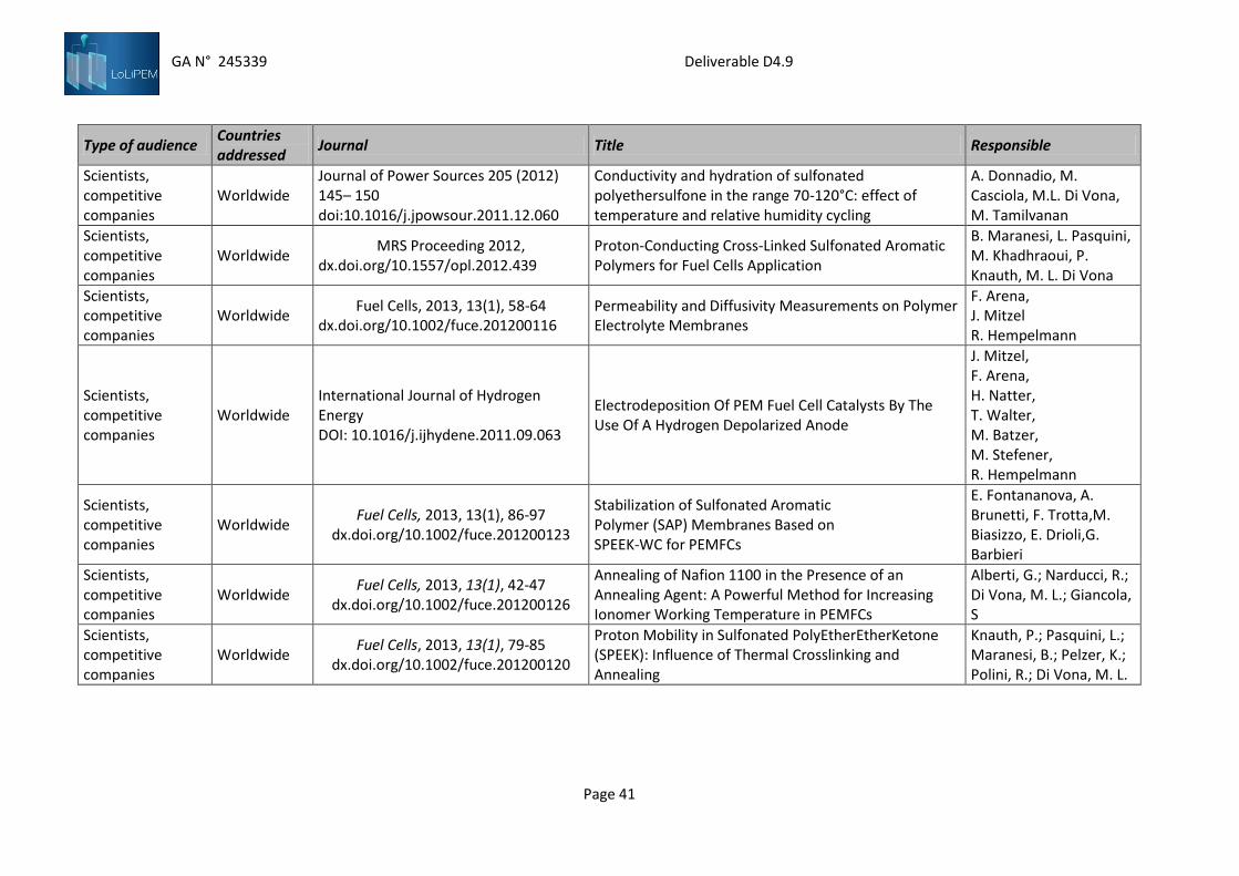
GA N° 245339 Deliverable D4.9
Page 41
Type of audience Countries addressed
Journal Title Responsible
Scientists, competitive companies
Worldwide Journal of Power Sources 205 (2012) 145– 150 doi:10.1016/j.jpowsour.2011.12.060
Conductivity and hydration of sulfonated polyethersulfone in the range 70-120°C: effect of temperature and relative humidity cycling
A. Donnadio, M. Casciola, M.L. Di Vona, M. Tamilvanan
Scientists, competitive companies
Worldwide MRS Proceeding 2012,
dx.doi.org/10.1557/opl.2012.439 Proton-Conducting Cross-Linked Sulfonated Aromatic Polymers for Fuel Cells Application
B. Maranesi, L. Pasquini, M. Khadhraoui, P. Knauth, M. L. Di Vona
Scientists, competitive companies
Worldwide Fuel Cells, 2013, 13(1), 58-64
dx.doi.org/10.1002/fuce.201200116 Permeability and Diffusivity Measurements on Polymer Electrolyte Membranes
F. Arena, J. Mitzel R. Hempelmann
Scientists, competitive companies
Worldwide International Journal of Hydrogen Energy DOI: 10.1016/j.ijhydene.2011.09.063
Electrodeposition Of PEM Fuel Cell Catalysts By The Use Of A Hydrogen Depolarized Anode
J. Mitzel, F. Arena, H. Natter, T. Walter, M. Batzer, M. Stefener, R. Hempelmann
Scientists, competitive companies
Worldwide Fuel Cells, 2013, 13(1), 86-97
dx.doi.org/10.1002/fuce.201200123
Stabilization of Sulfonated Aromatic Polymer (SAP) Membranes Based on SPEEK-WC for PEMFCs
E. Fontananova, A. Brunetti, F. Trotta,M. Biasizzo, E. Drioli,G. Barbieri
Scientists, competitive companies
Worldwide Fuel Cells, 2013, 13(1), 42-47
dx.doi.org/10.1002/fuce.201200126
Annealing of Nafion 1100 in the Presence of an Annealing Agent: A Powerful Method for Increasing Ionomer Working Temperature in PEMFCs
Alberti, G.; Narducci, R.; Di Vona, M. L.; Giancola, S
Scientists, competitive companies
Worldwide Fuel Cells, 2013, 13(1), 79-85
dx.doi.org/10.1002/fuce.201200120
Proton Mobility in Sulfonated PolyEtherEtherKetone (SPEEK): Influence of Thermal Crosslinking and Annealing
Knauth, P.; Pasquini, L.; Maranesi, B.; Pelzer, K.; Polini, R.; Di Vona, M. L.

GA N° 245339 Deliverable D4.9
Page 42
Type of audience Countries addressed
Journal Title Responsible
Scientists, competitive companies
Worldwide Fuel cells, 2013
in press dx.doi.org/10.1002/fuce.201200010
Cross-linking of sulfonated poly ether ether ketone by thermal treatment: how does the reaction occur?
B. Maranesi, H. Hou, R. Polini, E. Sgreccia,G. Alberti, R. Narducci, P. Knauth, M. L. Di Vona
Scientists, competitive companies
Worldwide Industrial & Engineering Chemistry Research, 2013 In press
More on NAFION conductivity decay at temperatures higher than 80°C: preparation and first characterization of in-plane oriented layered morphologies
Alberti, G.; Narducci, R.; Di Vona, M. L.; Giancola, S.
Scientists, competitive companies
Worldwide Zeitschrift fur Physikalische Chemie In press
Sulfonated Aromatic Polymers as Proton-Conducting Solid Electrolytes for Fuel Cells: a Short Review
Maria Luisa Di Vona Philippe Knauth
Scientists, competitive companies
Worldwide Z. Phys. Chem, 2013
in press dx.doi.org/10.1524/zpch.2013.0346
Electrocatalyst–Membrane Interface and Fuel Cell Performance with Sulfonated PolyEtherEtherKetone as Ionomer
F. Arena, J. Mitzel R. Hempelmann
List of the oral presentations at conference
Publishing date Conference title Type of audience Countries addressed Title presentation Responsible
29 August - 3 September 2010
XII International Symposium on Polymer Electrolytes (ISPE12), Italy
Scientists, competitive companies
Worldwide Development of stabilized SPEEK-WC membranes
E. Fontananova, G. Barbieri, F. Trotta, E. Drioli
29 August - 3 September 2010
XII International Symposium on Polymer Electrolytes (ISPE12), Italy
Scientists, competitive companies
Worldwide from Gas Diffusion Layers to Gas Difdfusion Electrodes directly by Electrodeposition
J. Mitzel, F. Arena, H. Natter, R. Hempelmann
29 August - 3 September 2010
XII International Symposium on Polymer Electrolytes (ISPE12), Italy
Scientists, competitive companies
Worldwide Aspects of Physical Chemistry of Aromatic Ionomers for Fuel Cells
P. Knauth, M. L. Di Vona

GA N° 245339 Deliverable D4.9
Page 43
Publishing date Conference title Type of audience Countries addressed Title presentation Responsible
29 August - 3 September 2010
XII International Symposium on Polymer Electrolytes (ISPE12), Italy
Scientists, competitive companies
Worldwide
A new representation of the instability maps of an ionomer at medium temperature: plots T-RH at constant values of the counter-elasticity index of Nafion 117 in the temperature range 50-140°C
G. Alberti, M. L. Di Vona, R. Narducci
4-6 June, 2010 7th Italy-Korea Workshop “Membranes for a clean environment”, Italy
Scientists, competitive companies
Italy Korea
Membrane operations in the energy field
E. Fontananova, G. Barbieri, F. Trotta, E. Drioli
June 2010
EMRS 2010 Spring Meeting June 2010 Palais des Congrès, Strasbourg, Symposyium O: Solid state ionics: exploring chemical and structural complexity of novel ionic conductors, France
Scientists, competitive companies
Worldwide New Generation Proton-Conducting Polymers For Fuel Cells
M. L. Di Vona (Invited lecture)
19-22 September 2010
2nd CARISMA International Conference on Progress in MEA Materials for Medium and high Temperature Polymer Electrolyte Fuel Cells, France
Scientists, competitive companies
Worldwide
Water-vapour sorption isotherms of Nafion 1100 membranes taking into account the permanent deformations provoked by some standard pre-treatment procedures usually performed before their use in fuel cells
G. Alberti, M. L. Di Vona, R. Narducci
November 7- 11, 2010
6th international symposium on high-tech polymer materials synthesis, characterization and applications, China
Scientists, competitive companies
Worldwide Advanced Thermal Treatments for High Durability Sulfonated Aromatic Polymers
M. L. Di Vona (Invited lecture)

GA N° 245339 Deliverable D4.9
Page 44
Publishing date Conference title Type of audience Countries addressed Title presentation Responsible
March 17-18, 2011
Workshop on “Long life membranes based on PTFA & SAPs: preparation and characterization”, Italy
Scientists, competitive companies
Worldwide Development of long life SAP membranes for PEMFCs based on SPEEK-WC
E. Fontananova, A. Brunetti, H. Hou, P. Knauth, F. Trotta, E. Drioli, G. Barbieri
March 17-18, 2011
Workshop on “Long life membranes based on PTFA & SAPs: preparation and characterization”, Italy
Scientists, competitive companies
Worldwide Study and Implementation of Advanced Control Technologies to Maximize PEM Fuel Cell Durability
A. Arce, J.O. Ossó, C. Bordons and L. F. Vega
March 17-18, 2011
Workshop on “Long life membranes based on PTFA & SAPs: preparation and characterization” , Italy
Scientists, competitive companies
Worldwide
Gravimetric determination of the water uptake of ionomeric membranes as a function of temperature at controlled relative humidity
M. Casciola, M. L. Di Vona and A. Donnadio
March 17-18, 2011
Workshop on “Long life membranes based on PTFA & SAPs: preparation and characterization” , Italy
Scientists, competitive companies
Worldwide Ex-situ stability test of Sulfonated Aromatic Polymers by Thermogravimetric Analysis
P. Knauth and H. Hou
March 17-18, 2011
Workshop on “Long life membranes based on PTFA & SAPs: preparation and characterization” , Italy
Scientists, competitive companies
Worldwide Mechanical analysis of Polymers M. Khadhraoui, H. Hou and P. Knauth
March 17-18, 2011
Workshop on “Long life membranes based on PTFA & SAPs: preparation and characterization” , Italy
Scientists, competitive companies
Worldwide Permeability and Diffusivity Measurements on Membranes for H2-PEMFC’s
F. Arena, R. Szamocki and R. Hempelmann
March 17-18, 2011
Workshop on “Long life membranes based on PTFA & SAPs: preparation and characterization” , Italy
Scientists, competitive companies
Worldwide Hybrid approach for improved SAP membranes
E. Sgreccia, P. Knauth and M. L. Di Vona

GA N° 245339 Deliverable D4.9
Page 45
Publishing date Conference title Type of audience Countries addressed Title presentation Responsible
March 17-18, 2011
Workshop on “Long life membranes based on PTFA & SAPs: preparation and characterization”, Italy
Scientists, competitive companies
Worldwide Permeability and Diffusivity Measurements on Membranes for H2-PEMFC’s
F. Arena, R. Szamocki and R. Hempelmann
24-27 May 2011 Nanomeeting 2011, Belarus Scientists, competitive companies
Belarus Membranes Based on SPEEK for Polymer Electrolyte Membrane Fuel Cells
M. L. Di Vona, P. Knauth, G. Auer
July 3-8, 2011 18th International Conference on Solid State Ionics Warsaw
Scientists, competitive companies
Worldwide Strategies for improvement of Sulfonated Aromatic Ionomer
P. Knauth (Keynote) and M. L. Di Vona
August 1-5, 2011 Thermec 2011, Quebec City, Canada
Scientists, competitive companies
Worldwide
Proton consucting sulfonated aromatic polymers: relation between macromolecular structure, water activity and proton mobility
P. Knauth (Keynote)
August 1-5, 2011 Thermec 2011, Quebec City, Canada
Scientists, competitive companies
Worldwide Proton-conducting high ionic exchange capacity aromatic ionomers for fuel cells application
M. L. Di Vona (Invited)
August 1-5 2011 Thermec 2011 Quebec City, Canada
Scientists, competitive companies
Worldwide Proton-Conducting High Ionic Exchange Capacity Aromatic Ionomers For Fuel Cells Application
M. L. Di Vona (Invited lecture)
March, 2012 International Workshop on “Electrocatalysis”, Germany
Scientists, competitive companies
Worldwide Thermally Annealed SPEEK and Its Application for Medium Temperature Hydrogen PEM Fuel cells
F. Arena J. Mitzel, M. L. Di Vona, G. Alberti, R. Hempelmann
May, 2012 International Workshop on “Fuel Cell Stack Assembly”, Spain
Scientists, competitive companies
Worldwide
Permeability and Diffusivity Measurements on Polymer Exchange Membranes for Hydrogen PEM FUEL CELLS
F. Arena M. L. Di Vona, R. Hempelmann

GA N° 245339 Deliverable D4.9
Page 46
Publishing date Conference title Type of audience Countries addressed Title presentation Responsible
May, 2012 E-MRS Spring 2012 – Symposium F , France
Scientists, competitive companies
Worldwide Solid State Proton Diffusion and Quasielastic Neutron Scattering
R. Hempelmann
May 29-30, 2012
3rd LoLiPEM International Workshop Fuel Cell Stack Assembly, Spain
Scientists, competitive companies
Worldwide New approach to control fuel cell stacks under variable loads
Alicia Arce,alCarlos Bordons and Lourdes F. Vega
May 29-30, 2012
3rd LoLiPEM International Workshop Fuel Cell Stack Assembly, Spain
Scientists, competitive companies
Worldwide Model predictive control for fuel cell systems
Carlos Bordons
May 29-30, 2012
3rd LoLiPEM International Workshop Fuel Cell Stack Assembly, Spain
Scientists, competitive companies
Worldwide Evaluation of membranes mass transport properties of polymer electrolyte membranes for PEMFC
Adele Brunetti, Enrica Fontananova, Enrico Drioli and Giuseppe Barbieri
May 29-30, 2012
3rd LoLiPEM International Workshop Fuel Cell Stack Assembly, Spain
Scientists, competitive companies
Worldwide Hurdles on the path to the hydrogen economy
Pedro Gómez-Romero
May 29-30, 2012
3rd LoLiPEM International Workshop Fuel Cell Stack Assembly, Spain
Scientists, competitive companies
Worldwide
Cross-linked proton-conducting membranes: an efficient strategy to improve sulfonated aromatic polymers for fuel cells
Maria Luisa Di Vona, Emanuela Sgreccia
May 29-30, 2012
3rd LoLiPEM International Workshop Fuel Cell Stack Assembly, Spain
Scientists, competitive companies
Worldwide
Static and dynamic mechanical measurements: what information can they provide for pem fuel cell technology?
P. Knauth, M. Khadhraoui

GA N° 245339 Deliverable D4.9
Page 47
Publishing date Conference title Type of audience Countries addressed Title presentation Responsible
July 9-10, 2012 8th International Symposium on Advanced Polymeric Materials, Kuala Lumpur
Scientists, competitive companies
Worldwide Proton Conducting hydrated acidic polymers: relation between proton mobility and proton concentration
P. Knauth (invited)
July 9-10, 2012 8th International Symposium on Advanced Polymeric Materials, Kuala Lumpur
Scientists, competitive companies
Worldwide Proton-conducting cross-linked sulfonated aromatic polymers for fuel cells application
M. L. Di Vona (Invited)
August 26-31, 2012
XIII International symposium on polymer electrolytes, Selfoss, Iceland
Scientists, competitive companies
Worldwide Proton-mobility in proton-conducting polymers
P. Knauth (invited) and M. Luisa Di Vona
August 26-31, 2012
XIII International symposium on polymer electrolytes, Selfoss, Iceland
Scientists, competitive companies
Worldwide Proton-conducting cross-linked sulfonated aromatic polymers for fuel cells application
M.L. Di Vona, B. Maranesi, L. Pasquini and P. Knauth
August 12-17, 2012
International Material Research conference, Cancun, Mexico
Scientists, competitive companies
Worldwide Proton-conducting hydrated acidic polymers: relations between polymer microstructure and proton mobility
P. Knauth and M. L. Di Vona
August 12-17, 2012
International Material Research conference, Cancun, Mexico
Scientists, competitive companies
Worldwide Sulfonated Aromatic Polymers for Fuel Cells
M. L. Di Vona and P. Knauth
November 21-23, 2012
Congreso Nacional de Pilas de Combustible
Scientists, competitive companies
Spain In-situ characterization of PEM membranes by AFM
I. Torres, A. Arce, J. O. Ossó, M.L. DiVona, L. F. Vega
November, 2012 GDCh Workshop – Energy transformation
Scientists, competitive companies
Germany Gasdiffusionselektroden für SPEEK-Elektrolytmembranen in Brennstoffzellen
F. Arena, D: Durneata; J. Mitzel, M. L. Di Vona, R. Hempelmann

GA N° 245339 Deliverable D4.9
Page 48
List of the poster presentations at conference
Publishing date
Conference title Type of audience Countries addressed
Title poster presentation Responsible
4-6 June, 2010 7th Italy-Korea Workshop “Membranes for a clean environment”, , Italy
Scientists, competitive companies
Italy Korea
New strategies to improve membrane durability for PEMFCs
E. Fontananova, A. Brunetti, G. Barbieri, F. Trotta, E. Drioli
19-22 September 2010
2nd CARISMA International Conference on Progress in MEA Materials for Medium and high Temperature Polymer Electrolyte Fuel Cells, France
Scientists, competitive companies
Worldwide Annealing of proton-conducting ionomers based on SPEEK
M. L. Di Vona, E. Sgreccia, P. Knauth, R. Narducci, G. Alberti
July 23-29, 2011
International Conference on Membranes and Membrane Processes, The Netherlands
Scientists, competitive companies
Worldwide Design and development of non-fluorinated polymer electrolyte membranes with improved stability
Fontananova E., Brunetti A., Hou H., Knauth P., Trotta F., Drioli E., Barbieri G
May, 2012 E-MRS Spring 2012 – Symposium F , France
Scientists, competitive companies
Worldwide
Permeability and Diffusivity Measurements on Polymer Exchange Membranes for Fuel Cell Applications
F. Arena, A. Brunetti, G. Barbieri, R. Hempelmann
September, 2012
Euromembrane 2012, England Scientists, competitive companies
Worldwide
Permeability and Diffusivity Measurements on Polymer Exchange Membranes for Fuel Cell Applications
F. Arena, J. Mitzel, D. Durneata, R. Hempelmann
Seminars
1) Arce. Advanced Control Technologies: Applications on Fuel Cell and CO2 Capture Sytems. Matgas Resarch Center. 11 February 2011. Barcelona.
2) Arce. Modeling of PEM fuel cell systems. Institut de Robòtica i Informàtica Industrial. Universidad Politécnica de Cataluña. 4 March 2011. Barcelona
3) Arce. On the Exploitation of MPC-based Formulations for Performance Enhancement of Fuel Cell Systems. Institut d’Organització I Control de sistemas
Industrials. Unversidad Politécnica de Cataluña. 4 May 2011. Barcelona.

GA N° 245339 Deliverable D4.9
Page 49
Other Issues
1) The LoLiPEM project partner: Cracow University of Technology – Bogna Grochola, LoLiPEM project
webpage: www.lolipem.eu, Webpage ,2010
2) The LoLiPEM project partner: Cracow University of Technology – Bogna Grochola, The LoLiPEM
project leaflet, Leaflets, 2010
3) The LoLiPEM project partner: Cracow University of Technology – Bogna Grochola, LoLiPEM project
short press release in Granty Europejskie (04.2010)
3.3.5. Summary
Finally, the dissemination methods were summarized in table below.
Constituency Dissemination methods Form of
comm
Examples
Media
Send press releases to journals, magazines,
and electronic publications
Post on list serves and websites
all See 4.3.1. (website)
Other
universities’
scientists and
students
Host or attend seminars O, D, E,
OE, DE
See 4.3.3, and 4.3.4., and
4.3.5. (books, publication,
conferences, posters,
seminars, website)
Policymakers
[EU]
Distribute summary document
Draft and send policy position statements
Send press releases
D, DE See 4.3.2 and 4.3.5.
Companies
Send a e-newsletter summarizing research in
progress
Host or attend seminars
Host community forums to discuss the
research
all
See 4.3.3, 4.3.4., and
4.3.5. (books, publication,
conferences, posters,
seminars, website)
Local
communities
Host of attend seminars
Host community forums to discuss the
research
Appeal for articles in local media sources
Participate in local events or conferences
all
See 4.3.3 and 4.3.5.
(books, publication,
conferences, posters,
seminars, website)
“green energy”
advocacy groups
and NGOs
Distribute flyers, brochures & research briefs
Participate in local events or conferences
Host or attend seminars
Host community forums to discuss the
research
Ask agencies to feature the research project
in their newsletters & websites
all See 4.3.5. (website)

GA N° 245339 Deliverable D4.9
Page 50
3.4. Dissemination actions – plans for the future
Partners plan additional dissemination actions beyond project time-frames. These activities are performed
mainly at the conferences. Forthcoming dissemination activities are focused on scientists – as a group of
audience – and are addressed to worldwide scientific community. Plans are summarized in Table below:
Table 16. Project deliverables – planned for publication:
Planned
date
Dissemination
methods
Type of action /
event
Constituency
/ type of
audience
Countries
addressed
Expected
size of
audience
Partner
/Beneficiary
responsible*
8-13
September
2013
O, D
Congress,
EUROMAT,
SEvilla, Spain
Scientists International 100
2 & 3
December
2013 O, D
Congress,
Thermec, Las
Vegas USA
Scientist International 100
2 & 3
August
2014 O, D
Congress, IMRC,
Cancoon, Mexico Scientist International 100
2 & 3
July 2013 D Publication Scientist International 2 & 3
* Beneficiary 1: CNR; Beneficiary 2: URoma2; Beneficiary 3: UProvence; Beneficiary 4: USaar; Beneficiary 5:
Edison; Beneficiary 6: Fumatech; Beneficiary 7: MatGas; Beneficiary 8: CUT

GA N° 245339 Deliverable D4.9
Page 51
4. STRATEGY OF EXPLOITATION
4.1. Introduction
The technology component consists of tools and techniques to implement effective knowledge
management practice which provides values to its business, employees, customers and partners. The tools
can further be classified into knowledge creation, knowledge integration, knowledge sharing and
knowledge utilization.
Figure 30. Technology strategy.
The various steps are described here:
Knowledge Creation - Knowledge is created either as explicit or tacit knowledge. Explicit
knowledge is put in paper or electronic format. It is recorded and made accessible to others. Tacit
knowledge is created in minds of people. This knowledge resides within individuals. This knowledge
needs to be transformed into explicit knowledge so that it can recorded and shared with others in
the organization.
Knowledge Storage - Knowledge is stored and organized in a repository. The decision on how and
where lies with the organization. But the objective of this phase to enable organization to be able
to contribute, organize and share knowledge with.
Knowledge Sharing - Knowledge is shared and accessed by people. They can either search or
navigate to the knowledge items.
Knowledge Utilization - This is end goal of knowledge practice. The knowledge management does
not have any value if knowledge created is not utilized to its potential. The more knowledge is
created as knowledge is applied and utilized.
And Measuring knowledge benefits (not shown) - No process can be improved if it is not measured
for success. The key to success of knowledge management is the ability to measure the
effectiveness of the implementation and narrowing it down to returns through revenue. The
monitoring and control on processes are necessary to identify opportunities for eliminating
redundancy and allow for continuous improvement.
Knowledge is utilized and commercialized in many ways. Many of these involve some form of codification
from tacit knowledge to knowledge in more explicit forms such as documents databases and computer
software. What starts as uncodified knowledge, often a set of ideas, is gradually shaped through dialogue
and expression into something more tangible, such as a process description or a product design, that finally

GA N° 245339 Deliverable D4.9
Page 52
emerges as products for sale.
Figure 31. Knowledge commercialization process.
Much knowledge in organizations is neither explicitly codified nor commercialized. thus many knowledge
management initiatives identify important tacit knowledge, held by a few experts, that is capable of
codification and would benefits many other people. knowledge can be commercialized in several ways:
selling it as part of an advisory service; developing methodologies as part of a consultancy; developing
training courses; converting it into information products such as databases or publications etc
Details on knowledge management and on IPR are provided by the Consortium Agreement that all
partners signed. Some of the major aspects concerning confidentiality, ownership of knowledge, patents
and access rights are shortly reported below:
Confidentiality: each partner treats information from other partners as confidential and not
disclose it to third parties unless it is obvious that the information is already publicly available.
Ownership of knowledge: knowledge is owned by the partners who carried out the work
generating the knowledge.
Patents: Partners who own patentable knowledge may, at their own expense, make applications
for patent or similar form of protection and shall supply details of each such application to the
other partners.
Access rights: Partners grant to each of the other partners royalty-free access right to knowledge
generated in the project to the extent needed to successfully perform the project.
The protecting intellectual assets highlights two-fold challenge. From a legal/contractual perspective,
nothing substitutes for a well -crafted Consortium Agreement. Those document contains the intellectual
asset terms and conditions each project partner must abide by during the collaboration. They also ensure
that collaborating researchers have the necessary rights to carry out the collaboration and take the fruits of
the work into the marketplace.
From the human behavior perspective, partners must ensure that collaborating researchers (esp.
working for Public Research Organizations like Universities) have an understanding of the relevant terms of
the contract, including what information must and must not be shared. The real challenge with protecting
intellectual assets is that they are both “leaky” and “sticky”. They leak out of the organization with every
visit of an outsider (defined as “third parties” – see section 8.4 of Consortium Agreement), and they stick in
the minds of anyone who hears them. It takes “a while” for the person who just learned interesting
information to convince themselves that they always knew that information, and therefore have a right to
use it. Providing and repeating the information to members of both sides of R&D process (researchers and
commercializing staffs in companies involved), with a specific focus on protecting sensitive information
during the course of the collaboration, pays enormous dividends in saving commercial potential of

GA N° 245339 Deliverable D4.9
Page 53
discoveries and findings.
Protection of know-how. The nature of intangible assets such as know-how and trade secrets is a barrier to
their protection. They are easily shared, travel effortlessly in peoples' minds, and resist being categorized
into neat little piles labeled proprietary and non-proprietary knowledge. To complicate matters further,
know-how is hard to talk about.
Consortium doesn’t distinguish between “know how”, which is information or skills required to do
something useful, or “trade secrets”, which are valuable information the firm takes specific actions to
protect. The real issue is protecting proprietary information, i.e., valuable knowledge a firm taking a part in
R&D project wishes to protect from unintended use.
The reality of the collaborative R&D process is that different legal agreements build on one another
as the collaboration moves through various phases. The Non-Disclosure Agreement (NDA) is normally the
first agreement in the series. It may be followed by an agreement covering development of new technology
such as a collaborative research agreement, a joint development agreement, or an agreement to purchase
developments from one of the parties. If the collaboration is successful, they are followed by agreements
that enable the operation of a business such as purchase agreements, joint marketing agreements, and
various types of licenses to assure each party has the necessary rights to operate their business.
In the LoLIPEM project majority of issues mentioned above is covering by “Consortium agreement” which
defines management of the background (section 11.3), and joint invention and foreground knowledge
management (section 11.2) as well.
[Joint invention] If, in the course of carrying out work on the Project, a joint invention, design or work is
made ‐ and more than one Party is contributor to it ‐ and if the features of such joint invention design or
work are such that it is not possible to separate them for the purpose of applying for, obtaining and/or
maintaining the relevant patent protection or any other Intellectual Property Right, the Parties concerned
agree that they may jointly apply to obtain and/or maintain the relevant right together with any other
Parties.
[Applying the results of joint invention and licensing to the third parties] The Parties concerned shall seek
to agree amongst themselves arrangements for applying for, obtaining and/or maintaining such right on a
case‐by‐case basis. As long as any such right is in force, each Party concerned shall be entitled to use and to
license such right without the consent of the other Parties, provided that the Party concerned shall be
informed in advance of any licensing to third parties. In case of licensing to third parties, appropriate
financial compensation shall be given to the other Parties concerned.
[Access rights] All Access‐rights {to background and foreground knowledge} granted in accordance with
{Consortium Agreement} are granted on a nonexclusive basis, expressly exclude any rights to sub‐license
and shall be made free of any transfer costs. (…) Foreground and Background shall be used only for the
purposes for which Access‐ rights to it have been granted and only for so long as is necessary for those
purposes.
Protecting the explicit knowledge by patenting. Protection of research results can be an important step in
the valorisation and commercialisation of LoLIPEM project results. Patent protection is the “strongest”
intellectual property right and also the most widely used for project results.
Before initialization of the patent procedure partners has to contact the patent attorney or other

GA N° 245339 Deliverable D4.9
Page 54
interface office and together try and asses the valorisation potential of research results. They shall examine
whether it is possible ornecessary to protect the research results e.g. through patenting and try to asses the
market value of the technology.
Subsequently university project partners shall contact companies which take a part in the project -
they might be interested in applying the technology into their products and services and they need a patent
or other formal tool of IP protection.
The way to best proceed, shall be decided on a case by case basis. When making the decision,
which of the following is the most important factor to consider for patenting: patentability (prior art, stat
bar issues, etc.), technical viability, or market factors?
Figure 32. Patenting decision. The most important factors.
As can be seen by the pie chart, the vast majority chose market factors. It means that technologies
recognize that can be patented, doesn’t mean it should be patented. If there is no market for the
technology, there is little point in spending time and resources determining whether it is technically viable,
what prior art exists, or whether a stat bar deadline has been passed.
So the trend is in the right direction. Some companies worry that, even if the technology has no
market potential, they need to obtain a patent in order to protect their right to use the innovation
themselves.
For a government lab or research organization (not a company), this is totally erroneous. Filing a
patent solely for the purpose of protecting your right to practice is a waste of money, because there is a
perfectly legal and inexpensive way to protect your rights: publish.
One trap that universities and government labs are particularly susceptible to is prestige patents.
These occur when policies create incentives for having as many patents as possible, regardless of their
commercial viability. Many institutions have “refereed papers or patents” as a metric. Yet sometimes the
patent is easier to obtain than the refereed paper. Solutions to this problem include:
If a technology doesn’t have market potential, stick to your guns and do not patent. Instead,
encourage and support the inventor in submitting a paper to a peer-reviewed journal.
Look for other venues for publication and reward them for that recognition.
Submit the technology for an external award.
In a screening, technology developers do a rapid analysis of market research and intellectual property (IP)
information to figure out if a technology has enough commercial potential to warrant the more in-depth
step of an assessment.
Has the technology been publicly disclosed and, if so, when (i.e., have you missed the 1-year
statutory bar deadline for filing for a patent)?

GA N° 245339 Deliverable D4.9
Page 55
Is it evolutionary or revolutionary?
Is it broadly applicable or relevant only to a few (or even a single) industries?
What is the estimated market size and how fast is it growing (or is it shrinking)?
Will it be easy/inexpensive or difficult/costly for licensees to adopt it?
What is the technology’s level of development?
How mature is the market? Has the window of opportunity closed, is it open now, or has it not yet
opened?
These are questions that can be answered well enough in a rapid screening to say either “Yes, this should be
studied more closely” or “No, it’s too unlikely that this will be successful” This type of rapid screening is
particularly important when you have a backlog of technologies in IP/patent portfolio.
In 2010, the US and European patent offices published a combined total of 1,801 granted fuel cell
patents. A comparison of this number to the total number of granted patents published in 2000 and 2005
(Figure 1) shows significant growth in intellectual property between 2000 and 2005, and again from 2005 to
2010. The increase equates to 347% growth in annual patent numbers over the decade15.
To determine to what extent the increase in fuel cell patents exceeded underlying growth in general
patent activity, we have estimated the number of fuel cell patents that would have resulted from no more
than average growth. These have been calculated from a 2000 baseline using overall patent growth rates
from WIPO . Had fuel cell patenting grown in line with general patenting, the number of fuel cell patents in
2005 would have been just 494 (compared to 861 actual) and in 2010 almost three times fewer at 627.
Figure 33. Increase in fuel cell patents number.
Baseline (average) = overall patent growth rates from WIPO.
Since applications for patents are only granted if they satisfy the requirement for novelty, the growth in
granted patents reflects substantial levels of innovation in fuel cell technology. It also underscores the rapid
progress of the industry towards commercialization in the first decade of this millennium, as granted
patents are only pursued and maintained by the assignee if a profit is expected from the invention.
The number of patents granted to each country by the US and European patent offices, collectively,
is shown in following figures (top ten countries, and countries with fewer than 100 patents in each year).
15 The 2011 Fuel Cell Patent Review [www.fuelcelltoday.com] Patents and applications relating to fuel cells were located by searches carried out on Thomson Reuters’ Aureka® IP analysis platform, using relevant keywords and the International Patent Classification (IPC) code H01M0008* for ‘Fuel Cells, Manufacture Thereof.

GA N° 245339 Deliverable D4.9
Page 56
Figure 34. Clean energy patents (granted 2000.2005.2010) per country.
Figure shows Japan and the USA leading the field, as we would expect. There have been significant
increases in absolute terms for both these countries, but fuel cell patenting in Japan accelerated sufficiently
during the decade to put Japan ahead of the USA by 2010.
This may be ascribed in part to a more widespread acceptance of fuel cells as commercial
technology in Japan, aided by government support for the Ene-Farm project (amongst others). After the
demonstration phase, which ran from 2005 to 2009, this support took the form of a ‘pull’ subsidy, with the
Japanese Government providing a significant percentage of the purchase cost of the Ene-Farm system. The
result has been thousands of fuel cell units sold to residential customers in Tokyo and elsewhere in Japan.
The number of patents from South Korea has also increased markedly from 2005 to 2010 –almost
putting it on a par with Germany, which has been active in this area for some time.
Large Korean corporations are responsible for pushing it to prominence, particularly Samsung and
to a lesser extent Hyundai and LG, but again significant support from the South Korean authorities for fuel
cell technology should be counted as a spur to innovation.
Figure above largely accords with the results of a recent patent-based study on clean energy
technology, jointly conducted by the EPO, the United Nations Environment Programme (UNEP) and the
International Centre for Trade and Sustainable Development (ICTSD)5. The study found that almost 80% of
innovation in clean energy technology originates in just six countries: Japan, the USA, Germany, the
Republic of Korea, France and the UK. Figure below excludes the USA, Japan, Germany and South Korea,
and shows those countries from which fewer than 100 patents but more than 5 patents originated in 2010.
Figure 35. Clean energy patents (granted 2000.2005.2010) per country
excl. Japan, USA, South Korea, & Germany.

GA N° 245339 Deliverable D4.9
Page 57
Steady growth from year to year is seen for the UK, Italy, Denmark and Australia, with progress in these
countries driven almost entirely by a handful of familiar names in the fuel cell industry. Significant growth
in France has seen increases in patents granted to a number of parties, significantly automakers Peugeot
and Renault, and the CEA (Commissariat à l'énergie atomique et aux énergies alternatives; the French
Alternative Energies and Atomic Energy Commission).
Figures confirm the growing dominance of Japan in this area: 20% of the top ten assignees in 2000
were Japanese corporations; this proportion increased to 50% in 2005 and to 70% in 2010. I.e. Samsung has
had a meteoric rise, from no presence in the top ranks in either 2000 or 2005, to number one on the list in
2010. It accounts for the bulk of Korea’s 177 granted patents in 2010 and has been almost solely
responsible for pushing that country into the top ten.
The presence of so many automotive manufacturers in the list for each year is particularly
encouraging, and underlines the determined effort by these companies to push fuel cell electric vehicles to
commercialization by 2015.16
The fuel cell patent numbers reflect the rapid technological progress in the industry from 2000 to 2010, and
the advent of commercialization in that period.
The extent of the growth we have reported, while extraordinary, is supported by statistics on clean energy
patents reported elsewhere. The Organisation for Economic Co-operation and Development (OECD) has
documented a significant rise in ‘green’ intellectual property from 1999 to 2008, with patents in renewable
energy showing the largest increase9. The WIPO 2010 indicators similarly show growth in the number of
PCT applications in four clean energy technologies: fuel cells, solar, wind and geothermal energy. From 584
applications in 2000, this had increased to 3,424 applications in 2009.
For obvious reasons, growth in clean energy technology can be expected to continue outstripping
underlying economic growth and its indicators, such as overall patent numbers.
16 The 2011 Fuel Cell Patent Review [www.fuelcelltoday.com]

GA N° 245339 Deliverable D4.9
Page 58
Whether there would be a return to the very rapid growth in applications between 2000 and 2005 remains
to be seen; our feeling is that this rate of increase is both unsustainable and unnecessary in the longer
term. More modest growth in patent numbers is a positive indicator if it reflects a progression from
research and development, and the intensive fund-raising phase, to commercial implementation within a
maturing industry.
Some predictions for the next five years we can make confidently: Japan will retain its position of
prominence in fuel cell patents, followed by the USA and Europe. These regions have built up a solid base
of intellectual property over the last decade and are well positioned to reap the benefits of that as
commercialization gains momentum. The most rapid growth in intellectual property will likely be in South
Korea, China and Taiwan, and we expect these to become powerhouses in the industry over the next
decade.
What this analysis has also confirmed is the extent of the commitment to fuel cell technology by
automotive OEMs. The patent numbers show that major manufacturers such as Toyota, Honda and General
Motors have sunk significant resources into this area. For fuel cell vehicles, and for the wide range of other
applications for fuel cells, the rapid increase in patent activity in the decade 2000 to 2010 reflects growing
confidence in fuel cell technology.
4.2. Exploitation actions
As we read in project proposal the following technology and knowledge exploitation models were
considered:17:
Partner 5, FumaTech, is active in the membrane market and is ready to commercialize any improved
ionomer membrane immediately. For this commercialization it is essential to have a demonstrator fuel cell
operating which proves the technical performance and the concerted action of ionomer and electrocatalysts.
FumaTech´s clients are manufacturer of MEAs or perhaps even of complete fuel cell stacks, and these clients
have to convinced. All decisions concerning exploitation have been made by the exploitation manager who
co-operated with technical and commercial staff of all the partners co-ordinating all exploitation issues,
such licences and patents.
FuMA-Tech GmbH “Functional Membranes and Plant Technology” combines the important tasks of
providing energy and water. At the sites in St. Ingbert (Saarland) and Vaihingen (Baden-Württemberg) in
Germany, FUMATECH is engaged in the field of fuel cell technology and membrane separation technology.
The company can look back on more than 15 years’ experience in polymer and membrane production and
in membrane separation technology. FUMATECH is a member of BWT-AG best-water-technology, the
leading water technology group in Europe.
Concerning the exploitation strategy and the intellectual property policy, any significant innovation
developed inside the project shall be protected by patents and any results which might have an EU
competitive advantage will be patented as soon as possible. Patenting cost and maintenance fees shall be
shared (decided on a case by case basis) by the partners having the main interest in the patent and bilateral
agreements concerning the protection of rights shall be made between partners with mutual interests. All
17 Annex I - „Description of Work” Chapter B3. Impact; B.3.2 Plan for the use and dissemination of foreground

GA N° 245339 Deliverable D4.9
Page 59
licensing issues shall be defined in detail in a Consortium Agreement to be discussed and signed by all the
partners before the end of project negotiation. In addition, the research institutes and universities shall
transfer the knowledge gained in this project both to their teaching activities, updating future engineers
and students, and to their interactions with other industries and research institutes.
Industrial partner show their particular interest in project results as follows:
From a technological viewpoint, FUMATECH ranks as the leading manufacturer of ion exchange
polymers and membranes, having comprehensive skills that range from the synthesis of raw and auxiliary
materials, to the conversion of these materials to membranes and finally to their application in industrial
membrane separation plants.
Polymer synthesis, manufacturing experience in film and membrane production as well as the
reliable operation of these membranes in industrial products have provided the Know-How for the
development and serial production of proton-conductive polymers and membranes for all known electro-
membrane applications including electrodialysis, acid and base dialysis, electrolysis, batteries and fuel cells.
Due to the in-house polymer production and coating plants for continuous membrane production,
FUMATECH is well equipped, even today, as a supplier of membranes for operations at pilot and industrial
level. The main area of FUMATECH’s competence lies at the heart of the fuel cell, namely the proton-
conductive membrane, fumapem®. The fuel cell strategy of FUMATECH is to supply all fuel cell industries
with (a) ionomers in bulk powder or solution, (b) membranes from fluorinated ionomers, non-fluorinated
ionomers and hybrid organic-inorganic composites for electrolysis, hydrogen fuel cells and direct methanol
fuel cells. Furthermore, FUMATECH provides coating services for e.g. toll production of tailored membranes
as well as for the production of catalyst coated membranes.
The main objective of LoLiPEM Project was to give a clear demonstration that long-life SPG&CHP
systems based on PEMFCHs operating at temperatures ≥ 100°C can be developed if stabilized ionomer
membranes and electrodes, prepared with new strategies are used for FCHs. FUMATECH is active in the
membrane market and is ready to commercialize any improved ionomer membrane immediately. For this
commercialization it was essential to have a demonstrator fuel cell operating which proves the technical
performance and the concerted action of ionomer and electrocatalysts. FUMATECH´s clients are
manufacturer of MEAs and complete fuel cell stacks.
The overall strategy of FUMATECH within LoLiPEM was the exploitation of project results for
commercialization of new PEMFC membranes based on:
the synthesis of crosslinked SAP membranes by innovative reactions
the preparation of stabilized PFSA and PFSA-ZrP composite membranes prepared by new tailor-
made annealing procedures.
FUMATECH was considering the following exploitation strategies within LoLiPEM project aiming at
facilitating and accelerating entry of PEMFCs to mass market:
Take licence of patents from project partners on new results regarding polymer and membrane
fabrication
Apply for patents on innovative results regarding polymer and membrane fabrication
Polymer production based on potentially low-cost material
Apply efficient crosslinking strategies on hydrocarbon membrane
Membrane production based on stabilizied PFSA and
Membrane production based on crosslinked SAP material (e.g. sPEEK)
Supply of ionomer and membranes for clients in the field of Fuel Cells

GA N° 245339 Deliverable D4.9
Page 60
Up-scaling of polymer and membrane production based on low-cost material
FUMATECH has considered the complete production chain starting from non-sulfonated PEEK to the ready-
to-use membrane, as show in the following process flow chart:
Figure 36. Process flow chart of production of sPEEK membranes.
This production chain comprises the following stages:
Scaled-up production of fumion® E (sulfonated PEEK): During the LoLiPEM project, FUMATECH has
developed and optimized the production of highly sulfonated PEEK including industrial scalability, cost and
environmental considerations. The process allows for a cost-effective and process-controlled
manufacturing, and a target-oriented and reproducible achievement of the degree of sulfonation of the
PEEK. The different stages of the production have been considered including the sulfonation as a batch
process versus a conti-process, the isolation by precipitation, the cleaning step by washing with water, the
purification by dialysis, the drying of the product and even the waste treatment.
Optimized solution preparation of sPEEK in DMSO for membrane casting: Optimized solution
composition and preparation have been developed which allow for reproducible and effective casting on
the FUMATECH’s continuous membrane production line. In particular the solvents, the solution
concentration, the solution viscosity, filtration and some important additives have been considered.
Optimized membrane production of sPEEK from optimized DMSO solution FUMATECH has
developed a robust process for the production of sPEEK membranes from optimized DMSO solutions on the
continuous membrane production line. The production process includes the coating of the polymer solution
onto a carrier foil, followed by a three-stage drying process. Process parameters were optimized in order to
obtain defect-free membranes. The process of the pilot-scale membrane production is fully compatible with
the standard large-scale membrane production enabling the rapid transfer and integration of the new
technology into the standard operation of manufacturing processes; and the subsequent exploitation of the
project results. The corresponding cost structure of polymer and membranes preparation has been
evaluated as well, comprising medium-scale polymer and membrane preparation and optionally the use of
ePTFE-reinforcement.
Optimized annealing / crosslinking process of sPEEK cast from DMSO: UROMA and FUMATECH
have developed the DMSO-mediated annealing process for crosslinking the sPEEK membranes in terms of
Polymer
Production
Solution
Preparation
Solution
Filtration
Membrane
Casting
Solvent
Evaporation
Annealing
Crosslinking
Activation
Conditioningblue = batch process
yellow = conti process

GA N° 245339 Deliverable D4.9
Page 61
temperature, time and procedure. This process is still a batch process and needs further optimization being
cost-effective and reproducible. Also the membrane activation after annealing is still a matter of
optimization.
Transfer of crosslinking concept to alternative highly sulfonated polymers: FUMATECH has
commenced exploring the transfer of the crosslinking concept to alternative highly sulfonated polymers This
concept has already been applied successfully to some sulfonated polymers – e.g. fumion® STO sulfonated
poly(ether sulfide sulfone) and fumion® ST sulfonated poly(sulfide sulfone).
Exploitation and use of crosslinked sPEEK for other applications: FUMATECH is considering the
exploitation and use of the developed crosslinked sPEEK membranes and other sulfonated hydrocarbon
membranes for other applications. Due to the specific properties and the potentially low-cost, these
membranes will be explored for the following applications:
DMFC applications: Due to the crosslinking and the corresponding insolubility, and due to the high
degree of sulfonation, the methanol crossover of these membranes is supposed to be significantly reduced,
while the proton conductivity is still high, leading to high fuel utilization and high performance in DMFC
applications.
Electrolysis for the production of hydrogen: Due to the high proton conductivity and high
mechanical stability, these membranes may be used in electrolysis application for hydrogen generation.
Humidifier: Due to the high degree of sulfonation, the water transfer rate through these
membranes should be high, which renders possible their application for humidifier.
Electrodialysis: These membranes may be used as cation-exchange membranes for water
treatment (desalination) in electrodialysis and other electrochemical processes, due to the potentially high
permselectivity, high conductivity and low-cost structure.
Partner 7, MATGAS Research Center is a strategic alliance, legally registered as a nonprofit Economical
Interest Group, among the company Carburos Metálicos- Air Products Group, the Spanish National Research
Council (CSIC) and the Autonomous University of Barcelona (UAB). The mission is to establish a center of
excellence in material science and gas application by combining the strengths of industrial, academic and
government institutions for the benefits of the founding partners and society.
The objective of MATGAS Research Center, with respect to the exploitation of results, is to develop novel
advanced control techniques for high temperature PEM (HT-PEM) fuel cell in different stationary
applications as combined heat and power systems. This technology will allow operating the systems in a
feasible way during long-term period maximizing the durability while keeping a high global efficiency. This
technology will be generic for high temperature PEM fuel cells and will also be applicable to non-stationary
applications such as transportation. The development of this technology requires a deep knowledge of
different areas such as material science (membranes, gas diffusion layers and catalysts), dynamic models,
control and instrumentation. The knowledge generated in the framework of the LoLiPEM project is a
matter of vital importance for MATGAS purposes and will be protected by proprietary rights. During this
project, different membrane technologies are going to be tested and the generalization of our control
approach for HT-PEM fuel cells will be developed. The technology developed by MATGAS in this project will
be an important innovation in the design of more competitive high temperature fuel cell systems for
combined heat and power applications. Once the technology is protected, development of commercial
systems will be possible in partnership with other participants of the LoLiPEM project, combining improved
membranes with advanced control techniques which will provide competitive FCH systems.

GA N° 245339 Deliverable D4.9
Page 62
Potential markets of the developed technology for stationary applications are backup systems for
residential power and heat supply and autonomous units for buildings, but this technology could also be
adapted to non-stationary applications, broadening the possible target markets. MATGAS, through its
partner Air Products, a leader in H2 production is involved in the research and development of this
technology due to its aforementioned promising potential.
These exploitations of results have been completed or are intended to be completed in the near future.