logic synthesis with vhdl combinational logic bob reese
TRANSCRIPT

Logic Synthesis with VHDLCombinational Logic
Bob ReeseElectrical Engineering Department
Mississippi State University
Mississippi State UniversityElectrical & Computer Engineering
Combinational Synthesis with VHDLCombSyn–2 Bob Reese 5/95
Logic Synthesis
⇒ Use of Logic Synthesis has become common industrial practice.
The advantages are many:
→ Technology portability
→ Design Documentation
→ Constraint Driven Synthesis
⇒ Two major languages are Verilog and VHDL. This tutorial will con-
ver logic synthesis via VHDL.
⇒ We will split the tutorials into three parts:
→ Introduction to VHDL via combinational synthesis examples
→ Sequential synthesis examples (registers, finite state
machines)
→ System examples (combined datapath and control)

Mississippi State UniversityElectrical & Computer Engineering
Combinational Synthesis with VHDLCombSyn–3 Bob Reese 5/95
Tutorial Caveats
⇒ Tutorial examples have been made as simple and portable as pos-
sible.
→ Will stay away from topics such as parameterization which
may involve vendor–dependent features.
→ Will also stay away from coding styles which involve type
conversion as this tends to add extra complications.
⇒ Examples have been tested with the Synopsys and Viewlogic syn-
thesis tools; most of the synthesized schematics shown in the
slides are from the Viewlogic synthesis tool. Some of the more
complex examples are only compatible with the Synopsys envi-
ronment
⇒ In these tutorials, the suggested styles for writing synthesizable
VHDL models come from my own experience in teaching an
ASIC design course for Senior/Graduate EE students.
⇒ Coverage of VHDL packages will be light; the block structural
statements and VHDL configurations are skipped. Generics are
not mentioned until late in the tutorial since support from a synthe-
sis point of view is vendor dependent.
⇒ This tutorial is no substitute for a good, detailed VHDL textbook or
the language reference manual. Get one or both!!!
Mississippi State UniversityElectrical & Computer Engineering
Combinational Synthesis with VHDLCombSyn–4 Bob Reese 5/95
VHDL Synthesis Subset
⇒ The VHDL language has a reputation for being very complex - that
reputation is well deserved!
⇒ Fortunately, the subset of VHDL which can be used for synthesis is
SMALL - very easy to learn.
⇒ Primary VHDL constructs we will use for synthesis:
→ signal assignment
nextstate <= HIGHWAY_GREEN
→ comparisons
= (equal), /= (not equal),
> (greater than), < (less than)
<= ( less than or equal), >= (greater than or equal)
→ logical operators
(and, xor, or, nand , nor , xnor , not )
→ ’if’ statement
if ( presentstate = CHECK_CAR ) then ....
end if | elsif ....
→ ’for’ statement (used for looping in creating arrays of
elements)
→ Other constructs are ’when else ’, ’case ’ , ’wait ’. Also ”:=” for
variable assignment.

Mississippi State UniversityElectrical & Computer Engineering
Combinational Synthesis with VHDLCombSyn–5 Bob Reese 5/95
General Comments on VHDL Syntax
⇒ Most syntax details will be introduced on an ’as–needed’ basis.
→ The full syntax of a statement type including all of its various
options will often NOT be presented; instead, these will be
introduced via examples as the tutorial progresses.
→There are many language details which will be glossed over or
simply skipped for the sake of brevity.
⇒ Generalities:
→ VHDL is not case sensitive.
→ The semicolon is used to indicate termination of a statement.
→ Two dashes (’––’) are used to indicate the start of a comment.
→ Identifiers must begin with a letter, subsequent characters
must be alphanumeric or ’_’ (underscore).
→ VHDL is a strongly typed language. There is very little
automatic type conversion; most operations have to operate
on common types. Operator overloading is supported in
which a function or procedure can be defined differently for
different argument lists.
Mississippi State UniversityElectrical & Computer Engineering
Combinational Synthesis with VHDLCombSyn–6 Bob Reese 5/95
Combinational Logic Examples
⇒ We will go through some combinational examples to introduce you
to the synthesizable subset of VHDL. Usually, we will demon-
strate multiple methods of implementing the same design.
⇒ Examples are:
→ 2 to 1 Mux
→ 8-level priority circuit
→ 3 to 8 Decoder
→ Synthesis boundary conditions
→ Ripple–carry adder

Mississippi State UniversityElectrical & Computer Engineering
Combinational Synthesis with VHDLCombSyn–7 Bob Reese 5/95
Model Template
entity model_name is
port (
list of inputs and outputs);end model_name;
architecture architecture_name of model_name isbegin ... VHDL concurrent statements
....
end architecture_name ;
Mississippi State UniversityElectrical & Computer Engineering
Combinational Synthesis with VHDLCombSyn–8 Bob Reese 5/95
2–to–1 MUX –– Using when else
library IEEE;use IEEE.std_logic_1164.all;
–– vhdl model for 2 to 1 mux, 8–bits wideentity mux2to1 isport( signal s: in std_logic; signal zero,one: in std_logic_vector(7 downto 0); signal y: out std_logic_vector(7 downto 0) );end mux2to1;
architecture behavior of mux2to1 isbegin
y <= one when (s = ’1’) else zero;
end behavior; zero
y8
8
one
8
s
mux2to1

Mississippi State UniversityElectrical & Computer Engineering
Combinational Synthesis with VHDLCombSyn–9 Bob Reese 5/95
Standard Logic 1164
library IEEE;use IEEE.std_logic_1164.all;
⇒ The LIBRARY statement is used to reference a group of previous-
ly defined VHDL design units (other entities or groups proce-
dures/functions known as ’packages’.
⇒ The USE statement specifies what entities or packages to use out
of this library; in this case ’USE IEEE.std_logic_1164.all’ imports
all procedures/functions in the std_logic_1164 package.
⇒ The std_logic_1164 package defines a multi–valued logic system
which will be used as the data types for the signals defined in our
examples.
→ The VHDL language definition had a built–in bit type which
only supported two values, ’1’ and ’0’ which was insufficient
for modeling and synthesis applications.
→ The 1164 standard defines a 9–valued logic system; only 4 of
these have meaning for synthesis:
’1’, ’0’, ’Z’ ( high impedance), ’–’ (don’t care).
⇒ The 1164 single bit type std_logic and vector type std_logic_vec-
tor (for busses) will be used for all signal types in the tutorial exam-
ples.
Mississippi State UniversityElectrical & Computer Engineering
Combinational Synthesis with VHDLCombSyn–10 Bob Reese 5/95
2/1 MUX Entity Declaration
entity mux2to1 isport( signal s: in std_logic; signal zero,one: in std_logic_vector(7 downto 0); signal y: out std_logic_vector(7 downto 0) );end mux2to1;
⇒ The entity declaration defines the external interface for the model.
⇒ The port list defines the external signals. The signal definition con-
sists of the signal name, mode, and type.
→For synthesis purposes (and for this tutorial), the mode can be
either in, out or inout.
⇒ In this tutorial, the signal types will be either std_logic (single bit) or
std_logic_vector (busses).
⇒ The array specification on the std_logic_vector type defines the
width of signal:
std_logic_vector (7 downto 0) (descending range)
std_logic_vector (0 to 7) (ascending range)
Both of these are 8–bit wide signals. The descending/ascending
range declaration will affect assignment statements such as:
y <= ”11110000”;
For descending rage, y(7) is ’1’; for ascending range y(0) is ’1’.

Mississippi State UniversityElectrical & Computer Engineering
Combinational Synthesis with VHDLCombSyn–11 Bob Reese 5/95
2/1 MUX Architecture Declaration
architecture behavior of mux2to1 isbegin
y <= one when (s = ’1’) else zero;
end behavior;
⇒ The architecture block specifies the model functionality.
→ The architecture name is user–defined. Multiple
architectures can be defined for the same entity. VHDL
configurations can be used to specify which architecture to
use for a particular entity.
→ This tutorial will only use one architecture per entity and it will
always be called behavior .
⇒ The ’when ... else’ statement is a conditional signal assignment
statement. ’When ... else’ statements can be chained such as:
signal_name <= value1 when condition1 else
value2 when condition2 else,
...... value N when conditionN else default_value;
⇒ The ’when ... else’ statement is a particular type of statement
known as a concurrent statement as opposed to a sequential
statement. The differences between concurrent and sequential
statements will be discussed in more detail later.
Mississippi State UniversityElectrical & Computer Engineering
Combinational Synthesis with VHDLCombSyn–12 Bob Reese 5/95
ZERO2
Y2
S
Y
BA
MX2
ONE2S
ZERO1
S
Y
BA
MX2
ONE1
Y1
ONE7
S
Y
BA
MX2
Y7
ZERO7
ONE0
S
Y
BA
MX2
ZERO0
Y0
ZERO5
S
Y
BA
MX2
Y5
ONE5
ONE6
S
Y
BA
MX2
Y6
ZERO6
Y4
S
Y
BA
MX2
ZERO4
ONE4
ONE3
S
Y
BA
MX2
ZERO3
Y3

Mississippi State UniversityElectrical & Computer Engineering
Combinational Synthesis with VHDLCombSyn–13 Bob Reese 5/95
2/1 MUX Architecture Using Booleans
architecture behavior of mux2to1 is signal temp: std_logic_vector(7 downto 0);
begin temp <= (s, s, s, s, others => s); y <= (temp and one) or (not temp and zero);
end behavior;
⇒ Boolean operators are used in an assignment statement to gener-
ate the mux operation.
⇒ The s signal cannot be used in a boolean operation with the one or
zero signals because of type mismatch (s is a std_logic type, one/
zero are std_logic_vector types)
→ An internal signal of type std_logic_vector called temp is
declared. Note that there is no mode declaration for internal
signals. The temp signal will be used in the boolean
operation against the zero/one signals.
⇒ Every bit of temp is to be set equal to the s signal value. An array
assignment will be used; this can take several forms:
temp <= (others => s); ’others’ keyword gives default value
temp <= (s, s, s, s, s, s, s, s) ; positional assignment, 7 downto 0
temp <= (4=>s, 7=>s, 2=>s, 5=>s, 3=>s, 1=>s, 6=>s, 0=>s) ;
named assignment
or combinations of the above.
Mississippi State UniversityElectrical & Computer Engineering
Combinational Synthesis with VHDLCombSyn–14 Bob Reese 5/95
2/1 MUX Architecture Using a Process
architecture behavior of mux2to1_8 isbegin comb: process (s, zero, one) begin y <= zero; if (s = ’1’) then y <= one; end if; end process comb;end behavior;
⇒ This architecture uses a process block to describe the mux opera-
tion.
→ The process block itself is considered a single concurrent
statement.
→ Only sequential VHDL statements are allowed within a
process block.
→Signal assignments are assumed to occur sequentially so that
an assignment can supercede a previous assignment to the
same signal.
→ ’if ... else’, ’case’, ’for ... loop’ are sequential statements.
⇒ The list of signals after the process block is called the sensitivity
list; an event on any of these signals will cause the process block
to be evaluated during model simulation.

Mississippi State UniversityElectrical & Computer Engineering
Combinational Synthesis with VHDLCombSyn–15 Bob Reese 5/95
8–level Priority Encoder
–– vhdl model for 8 level priority circuit–– IO Interface Declaration
entity priority is port ( signal y1, y2, y3, y4, y5, y6, y7: in std_logic; signal vec: out std_logic_vector(2 downto 0) );end priority;
–– Architecture bodyarchitecture behavior of priority isbegin process (y1,y2,y3,y4,y5,y6,y7) begin
if (y7 = ’1’) then vec <= ”111”;elsif (y6 = ’1’) then vec <= ”110”;elsif (y5 = ’1’) then vec <= ”101”;elsif (y4 = ’1’) then vec <= ”100”;elsif (y3 = ’1’) then vec <= ”011”;elsif (y2 = ’1’) then vec <= ”010”;elsif (y1 = ’1’) then vec <= ”001”;else vec <= B”000”;end if;
end process;end behavior;
y1y2y3y4y5y6y7
vec
3
Uses ’elsif’ construct for logic
priority
Mississippi State UniversityElectrical & Computer Engineering
Combinational Synthesis with VHDLCombSyn–16 Bob Reese 5/95
WIR:priority
SCH:priority
priority
SHEET 1 OF 1
6 Jan 94 13:36
1 2 3 4
1 2 3 4
FE
DC
BA
FE
DC
BA
Y7
Y3
NAND2B
A BY
Y2
YCB
AO1A
A
Y1
C DB
Y
A
AO2
YA B
NOR2
YCB
AO1A
A
YCB
AO1A
A
YOR4
B C DA
Y4
Y5
Y6
VEC2
VEC0
VEC1

Mississippi State UniversityElectrical & Computer Engineering
Combinational Synthesis with VHDLCombSyn–17 Bob Reese 5/95
Priority Encoder again.....
⇒ In a process, the ordering of sequential statements which affect a
common output define the priority of those assignments.
→ By using normal ’if’ statements and reversing the order of the
assignments we achieve the same results as with the
chained ’elsif’ statements.
–– Architecture bodyarchitecture behavior of priority isbegin process (y1,y2,y3,y4,y5,y6,y7) begin
vec <= ”000”;if (y1 = ’1’) then vec <= ”001”; end if;if (y2 = ’1’) then vec <= ”010”; end if;if (y3 = ’1’) then vec <= ”011”; end if;if (y4 = ’1’) then vec <= ”100”; end if;if (y5 = ’1’) then vec <= ”101”; end if;if (y6 = ’1’) then vec <= ”110”; end if;if (y7 = ’1’) then vec <= ”111”; end if;
end process;end behavior; Since ’y7’ is tested last it will have highest
priority.
Mississippi State UniversityElectrical & Computer Engineering
Combinational Synthesis with VHDLCombSyn–18 Bob Reese 5/95
3 to 8 Decoder Example
entity dec3to8 is port ( signal sel: in std_logic_vector(2 downto 0); –– selector signal en: in std_logic; –– enable signal y: out std_logic_vector(7 downto 0) –– outputs are low true); end dec3to8;
architecture behavior of dec3to8 isbegin process (sel,en) begin y <= ”11111111”; if (en = ’1’) then
case sel iswhen ”000” => y(0) <= ’0’;
when ”001” => y(1) <= ’0’; when ”010” => y(2) <= ’0’; when ”011” => y(3) <= ’0’; when ”100” => y(4) <= ’0’; when ”101” => y(5) <= ’0’; when ”110” => y(6) <= ’0’; when ”111” => y(7) <= ’0’; end case; end if; end process;end behavior;
’case’ statement used forimplementation

Mississippi State UniversityElectrical & Computer Engineering
Combinational Synthesis with VHDLCombSyn–19 Bob Reese 5/95
WIR:dec3to8
SCH:dec3to8
dec3to8
SHEET 1 OF 16 Jan 94 13:48
1
2
3
4
5
6
1
2
3
4
5
6
DCBA
DCBA
Y7
SEL1
OR3B
C
Y
A
B
SEL0
AY
B OR2B
OR2A
AY
BEN
A
C
B YOR3 Y0
SEL2
Y
C
A
BNAND3B Y2
Y1
A
C
B YOR3
OR3B
C
Y
A
BY6
Y
C
A
BNAND3B Y4
Y
C
A
BNAND3B Y3
Y
C
A
BNAND3B Y5
Mississippi State UniversityElectrical & Computer Engineering
Combinational Synthesis with VHDLCombSyn–20 Bob Reese 5/95
A Common Error
⇒ When using processes, a common error is to forget to assign an
output a default value. ALL outputs should have DEFAULT val-
ues!!!!
→ If there is a logical path in the model such that an output is not
assigned any value then the synthesizer will assume that the
output must retain its current value and a latch will be
generated.
⇒ Example: In dec3to8.vhd do not assign ’y’ the default value of
B”11111111”. If en is 0, then ’y’ will not be assigned a value!
process (sel,en)begin––––– y <= ”11111111”; if (en = ’1’) then ..........
Comment out the default assignment to ’y’.
⇒ In the new synthesized logic, all ’y’ outputs are latched!

Mississippi State UniversityElectrical & Computer Engineering
Combinational Synthesis with VHDLCombSyn–21 Bob Reese 5/95
SEL1
SEL0
Y3
Q
GD
DL1
Y
CBA
AND3A
Y2
Q
GD
DL1
Y
CBA
AND3B
Y1
Q
GD
DL1
Y
CBA
AND3B
SEL2
YBA
OR2A
EN
OR2B
A BY
Y
CBA
NOR3
Q
GD
DL1
Y0
Y7
Q
GD
DL1
Y
CBA
AND3A
Y4
Q
GD
DL1
Y
CBA
NOR3
Y
CBA
AND3B
Q
GD
DL1
Y5
Y
CBA
AND3B
Q
GD
DL1
Y6
GND
Mississippi State UniversityElectrical & Computer Engineering
Combinational Synthesis with VHDLCombSyn–22 Bob Reese 5/95
Alternative 3–to–8 Decoder
–– vhdl model for the 3 to 8 decoder–– uses conditional signal assignments–– which are concurrent statements
entity dec3to8_alt is port ( signal sel: in std_logic_vector(2 downto 0); –– selector signal en: in std_logic; –– enable
signal y: out std_logic_vector(7 downto 0) –– outputs are low true);end dec3to8_alt;
architecture behavior of dec3to8_alt isbegin
y(0) <= ’0’ when (en = ’1’ and sel = ”000”) else ’1’;
y(1) <= ’0’ when (en = ’1’ and sel = ”001”) else ’1’;
y(2) <= ’0’ when (en = ’1’ and sel = ”010”) else ’1’;
y(3) <= ’0’ when (en = ’1’ and sel = ”011”) else ’1’;
y(4) <= ’0’ when (en = ’1’ and sel = ”100”) else ’1’;
y(5) <= ’0’ when (en = ’1’ and sel = ”101”) else ’1’;
y(6) <= ’0’ when (en = ’1’ and sel = ”110”) else ’1’;
y(7) <= ’0’ when (en = ’1’ and sel = ”111”) else ’1’;
end behavior;
Conditional signalassignment usedfor each output bit.

Mississippi State UniversityElectrical & Computer Engineering
Combinational Synthesis with VHDLCombSyn–23 Bob Reese 5/95
Generic Decoder
⇒ Shown below is an architecture block for a generic decoder:
architecture behavior of generic_decoder isbegin process (sel, en) begin y <= (others => ’1’) ; for i in y’range loop if ( en = ’1’ and bvtoi(To_Bitvector(sel)) = i ) then y(i) <= ’0’ ; end if ; end loop; end process;end behavior;
⇒ This architecture block can be used for any binary decoder ( 2 to 4,
3 to 8, 4 to 16, etc).
⇒ The ’for ... loop’ construct is used to repeat a sequence of state-
ments.
→ The y’range is the range of values for loop variable ’i’. The
’range attribute of the signal ’y’ is defined as the array range
of the signal. In this case, ’i’ will vary from 7 to 0 if the array
range of ’y’ was defined as ”7 downto 0”.
→ Other attributes useful for synthesis are: ’LEFT, ’RIGHT (left,
right array indices); ’HIGH, ’LOW (max, min array indices);
’EVENT (boolean which is true if event occurred on signal).
Mississippi State UniversityElectrical & Computer Engineering
Combinational Synthesis with VHDLCombSyn–24 Bob Reese 5/95
Generic Decoder (cont.)
....
for i in y’range loop if ( en = ’1’ and bvtoi(To_Bitvector(sel)) = i ) then y(i) <= ’0’ ; end if ;
⇒ In order to compare loop variable i with the value of sel, a type con-
version must be done on sel to convert from std_logic_vector to
integer.
→ The Standard Logic 1164 package defines a conversion from
std_logic_vector to bit_vector (bit_vector is a primitive VHDL
type).
⇒ Unfortunately, the VHDL language standard does not define type
conversions between bit_vector and integer; these conversion
functions are vendor dependent.
→ ’bvtoi’ is the Synopsys bit_vector to integer conversion
function; ’vlb2int’ is the Viewlogic equivalent; the Cypress
WARP equivalent is ’bv2i’.

Mississippi State UniversityElectrical & Computer Engineering
Combinational Synthesis with VHDLCombSyn–25 Bob Reese 5/95
Synthesis Boundary Conditions
–– synthesis ’boundary’ conditions..entity boundtest is port ( signal a,b,c: in std_logic; signal w, x, y, z_low, z_high: out std_logic); end boundtest;
architecture behavior of boundtest isbegin
–– x and y reduce to the same logic equation–– the w output should be just a wire from c...–– the z_low output will be ’0’, the z_high will be ’1’ x <= a or b; y <= a or ( (b and not c) or (b and c)); w <= (c and b) or (c and not b); z_low <= b and not b; z_high <= b or not b;
end behavior;
What happens when:
Two outputs are reduced to the same logic equation?
An output is is reduced to ’0’, ’1’ or to a primary input?
Mississippi State UniversityElectrical & Computer Engineering
Combinational Synthesis with VHDLCombSyn–26 Bob Reese 5/95
WIR:boundtest
SCH:boundtestboundtest
SHEET 1 OF 1
6 Jan 94 13:55
1 2 3 4
1 2 3 4
FE
DC
BA
FE
DC
BA
WINVA
AY
INVA
AY
C
INVA
AY
INVA
AY
Z_HIGH
B A
YNAND2B
A BY
NAND2B
A BY
X
INVA
AY
INVA
AY
Z_LOW
VDD
GND

Mississippi State UniversityElectrical & Computer Engineering
Combinational Synthesis with VHDLCombSyn–27 Bob Reese 5/95
Ripple Carry Adder
Library IEEE;use IEEE.std_logic_1164.all;
entity adder4 is port ( signal a,b: in std_logic_vector (3 downto 0); signal cin: in std_logic; signal sum: out std_logic_vector(3 downto 0); signal cout: out std_logic); end adder4;
architecture behavior of adder4 is signal c: std_logic_vector(4 downto 0); begin process (a,b,cin,c) begin c(0) <= cin; for i in 0 to 3 loop sum(i) <= a(i) xor b(i) xor c(i); c(i+1) <= (a(i) and b(i)) or
(c(i) and (a(i) or b(i))); end loop; cout <= c(4); end process; end behavior;
Explicit CarryInand CarryOut
Temporary signalto hold internalcarries.
Use Looping construct tocreate logic for ripple carryadder.
Mississippi State UniversityElectrical & Computer Engineering
Combinational Synthesis with VHDLCombSyn–28 Bob Reese 5/95
WIR:adder4_alt
SCH:adder4_alt
adder4_alt
SHEET 1 OF 1
6 Jan 94 14:07
1 2
1 2
FE
DC
BA
FE
DC
BA
B3
A3
A BY
XOR
A BY
XOR
YCBA
AO1
CY
OA1
A B
CIN
A BY
XOR
A BY
XOR
B0
CY
OA1
A BA0
YCBA
AO1
A2
A BY
XOR
YCBA
AO1
CY
OA1
A BB2
A BY
XOR
YCBA
AO1
CY
OA1
A BA1
A BY
XOR
A BY
XOR
B1
SUM1
SUM2
SUM0
COUT
SUM3

Mississippi State UniversityElectrical & Computer Engineering
Combinational Synthesis with VHDLCombSyn–29 Bob Reese 5/95
Ripple Carry Adder Comments
⇒ The Standard Logic 1164 package does not define arithmetic op-
erators for the std_logic type.
⇒ Most vendors supply some sort of arithmetic package for 1164
data types.
→ Some vendors also support synthesis using the ’+’ operation
between two std_logic signal types (Synopsis). Others
provide an explicit function call (Viewlogic).
→ For code portability, it is best to avoid use of vendor–specific
arithmetic functions.
Mississippi State UniversityElectrical & Computer Engineering
Combinational Synthesis with VHDLCombSyn–30 Bob Reese 5/95
Summary
⇒ Logic synthesis offers the following advantages:
→ Faster design time, easier to modify
→ The synthesis code documents the design in a more readable
manner than schematics.
→ Different optimization choices (area or speed)
⇒ Several combinational VHDL examples were examined.
→ Both concurrent and sequential statements can be used to
specify combination logic – which you use is up to individual
preference.

Logic Synthesis with VHDLSequential Circuits
Bob ReeseElectrical Engineering Department
Mississippi State University
Mississippi State UniversityElectrical & Computer Engineering
Sequential CircuitsSeqSyn–2 Bob Reese 5/95
Sequential Circuits
⇒ Logic which contains both combinational logic and storage ele-
ments form sequential circuits. All sequential circuits can be di-
vided into a combinational block and a storage element block.
Combinational Logic
State Flip–Flops
Inputs Outputs
NextStatePresentStateCLK
Single Phase Sequential System
⇒ The above diagram shows a single-phase sequential system. In a
single-phase system the storage elements are edge–triggered
devices (flip-flops).
→ Moore–type outputs are a combinatorial function of
PresentState signals.
→ Moore–type outputs are a combinatorial function of both
PresentState and external input signals.
⇒ Multiple-phase design is also supported since latches can be syn-
thesized as the storage elements.

Mississippi State UniversityElectrical & Computer Engineering
Sequential CircuitsSeqSyn–3 Bob Reese 5/95
Sequential Template
library declarations
entity model_name isport (
list of inputs and outputs);end model_name;
architecture behavior of model_name isinternal signal declarations begin
–– the state process defines the storage elements state: process ( sensitivity list –– clock, reset, next_state inputs)
beginvhdl statements for state elements
end process state;
–– the comb process defines the combinational logic comb: process ( sensitivity list –– usually includes all inputs)
beginvhdl statements which specify combinational logic
end process comb;end behavior;
Mississippi State UniversityElectrical & Computer Engineering
Sequential CircuitsSeqSyn–4 Bob Reese 5/95
8–bit Loadable Register with Asynchronous clear
library ieee;use ieee.std_logic_1164.all;
entity reg8bit is port ( signal clk, reset, load: in std_logic; signal din: in std_logic_vector(7 downto 0); signal dout: out std_(7 downto 0));end reg8bit;
architecture behavior of reg8bit issignal n_state,p_state : std_logic_vector(7 downto 0);begin
dout <= p_state;
comb: process(p_state,load,din)begin n_state <=p_state; if (load=’1’) then n_state <= din; end if;end process comb;
state: process(clk, reset)beginif (reset = ’0’) then p_state <= (others => ’0’);elsif (clk’event and clk = ’1’) then p_state <= n_state; end if;end process state;
end behavior;

Mississippi State UniversityElectrical & Computer Engineering
Sequential CircuitsSeqSyn–5 Bob Reese 5/95
reg8bit State Process
state: process(clk, reset)beginif (reset = ’0’) then p_state <= (others => ’0’);elsif (clk’event and clk = ’1’) then p_state <= n_state; end if;end process state;
⇒ The state process defines a storage element which is 8–bits wide,
rising edge triggered, and had a low true asynchronous reset.
→ The output of this process is the p_state signal.
→ Note that the reset input has precedence over the clock in
order to define the asynchronous operation.
→ The ’event attribute is used to detect a change in the clock
signal; comparing the current clock value against ’1’ implies
that p_state gets the n_state value on a 0 to 1 transition
(rising edge).
→ The state holding action of the process arises from the fact
that p_state is not assigned a value is reset is not asserted
and a rising clock edge does not occur.
Mississippi State UniversityElectrical & Computer Engineering
Sequential CircuitsSeqSyn–6 Bob Reese 5/95
WIR:reg8bit
SCH:reg8bit
reg8bit
SHEET 1 OF 16 Jan 94 14:25
1
2
3
4
5
6
1
2
3
4
5
6
EDCBA
EDCBA
CLK
LOAD
CLEAR_B
DIN3
RESET_B
OR2A
AY
BA
YB OR2B
CLR
CLK
D Q
DFC1B
CY
BAO1C
AOR2A
AY
B
OR2A
AY
BCLR
CLK
D Q
DFC1BCY
BAO1C
A
DIN2
OR2A
AY
B
CY
BAO1C
A
CLR
CLK
D Q
DFC1B
DIN0
OR2A
AY
B
CLR
CLK
D Q
DFC1B
CY
BAO1C
A
DIN1
OR2A
AY
B
CLR
CLK
D Q
DFC1B
CY
BAO1C
A
DIN6
OR2A
AY
B
CLR
CLK
D Q
DFC1B
CY
BAO1C
A
DIN7
OR2A
AY
B
CY
BAO1C
A
CLR
CLK
D Q
DFC1B
OR2A
AY
B
CY
BAO1C
A
DIN5
DIN4
CLR
CLK
D Q
DFC1B
DOUT5
DOUT4
DOUT7
DOUT6
DOUT1
DOUT0
DOUT2
DOUT3

Mississippi State UniversityElectrical & Computer Engineering
Sequential CircuitsSeqSyn–7 Bob Reese 5/95
wait Statement
⇒ An alternative method of specifying the storage elements is shown
below:
state: processbeginwait until ((clk’event and clk = ’1’) or (reset = ’0’));if (reset = ’0’) then p_state <= (others => ’0’); else p_state <= n_state; end if;end process state;
⇒ The wait statement is a sequential statement.
⇒ The wait statement causes a suspension of a process or proce-
dure until the condition clause is satisfied.
⇒ The signals used in the condition clause form an implicit sensitivity
list for the wait statement.
→ Can use ’wait on sig1, sig2, ..sigN until condition_clause’ to
explicitly specify the sensitivity list.
→ Note that the process has no sensitivity list.
⇒ ’if’ statements used with processes generally give more flexibility
and control than ’wait’ statements .
Mississippi State UniversityElectrical & Computer Engineering
Sequential CircuitsSeqSyn–8 Bob Reese 5/95
Finite State Machine Example
HGHL:GRNFL:RED
TIMER
HL:YELFL:RED
ALARM
HL:REDFL:GRN
ALARM + CAR
HL:REDFL:YEL
ALARM
HY
FG
FY
HG
Traffic Light Controller
T
F
HGC
CAR
F
F
T
T
F
F
T
Upon RESET enter state HGC
start timer with short value
start timer with long value
HL:GRNFL:RED
T→START_SHORT_TIMER
T→START_LONG_TIMER
T→START_SHORT_TIMER
T→START_LONG_TIMER

Mississippi State UniversityElectrical & Computer Engineering
Sequential CircuitsSeqSyn–9 Bob Reese 5/95
Traffic Light Controller Block Diagram
SHORT REGLONG REG
TimerIn
N
0/1 0
1
select
load en
start_Astart_short_timer
start_long_timer start_B
alarm
Port APort B
count
car
fl hl
TLC Control
timer
Timer
long load
short load
car
fl hl count
N N
2 2
Glue
Mississippi State UniversityElectrical & Computer Engineering
Sequential CircuitsSeqSyn–10 Bob Reese 5/95
VHDL For Traffic Light FSM Control
library ieee;use ieee.std_logic_1164.all;–– vhdl model for the Traffic Light Control, sync reset, encoded statesentity tlc_enc is port( signal reset, car, timer, clk: in std_logic; signal stateout: out std_logic_vector(2 downto 0); signal highway_light, farm_light: out std_logic_vector(1 downto 0); signal start_short_timer, start_long_timer: out std_logic );end tlc_enc;architecture behavior of tlc_enc is
constant HGC: std_logic_vector(2 downto 0) := ”000”; constant HY: std_logic_vector(2 downto 0) := ”001”;constant FG: std_logic_vector(2 downto 0) := ”010”; constant FY: std_logic_vector(2 downto 0) := ”011”; constant HG: std_logic_vector(2 downto 0) := ”100”;
constant GREEN: std_logic_vector(1 downto 0) := ”00”; constant YELLOW: std_logic_vector(1 downto 0) := ”01”; constant RED: std_logic_vector(1 downto 0) := ”11”;
signal p_state, n_state : std_logic_vector(2 downto 0);
beginstateout <= p_state;statereg: process(clk, reset) if (reset = ’0’) then p_state <= HGC; elsif (clk’event and clk = ’1’) then p_state <= n_state; end if; end process statereg;
State assignments

Mississippi State UniversityElectrical & Computer Engineering
Sequential CircuitsSeqSyn–11 Bob Reese 5/95
VHDL For Traffic Light FSM (cont)
comb:process(car, timer, p_state) begin –– default assignments –– VERY IMPORTANT start_short_timer <= ’0’; start_long_timer <= ’0’; –– by default, stay in same state!!! n_state <= p_state; highway_light <= GREEN; farm_light <= RED;
if p_state = HG then highway_light <= GREEN; farm_light <= RED; if (timer = ’1’) then n_state <= HGC; end if; end if;
if p_state = HGC then highway_light <= GREEN; farm_light <= RED; if car = ’1’ then n_state <= HY; start_short_timer <= ’1’; end if; end if;
if p_state = HY then highway_light <= YELLOW; farm_light <= RED; if timer = ’1’ then n_state <= FG; start_long_timer <= ’1’; end if; end if;
All outputs should beassigned defaultvalues!! If you do notassign default valuesthen outputs may getsynthesized withoutput latches!
Use ’if’ statementsto enumeratestates.
Start timer withshort timeout value(yellow light).
Start timer withlong timeout value.
Mississippi State UniversityElectrical & Computer Engineering
Sequential CircuitsSeqSyn–12 Bob Reese 5/95
VHDL For Traffic Light FSM Control(cont.)
if p_state = FG then highway_light <= RED; farm_light <= GREEN; if timer = ’1’ or car = ’0’ then n_state <= FY; start_short_timer <= ’1’; end if; end if;
if p_state = FY then highway_light <= RED; farm_light <= YELLOW; if timer = ’1’ then n_state <= HG; start_long_timer <= ’1’; end if; end if;
end process comb;
end behavior;

Mississippi State UniversityElectrical & Computer Engineering
Sequential CircuitsSeqSyn–13 Bob Reese 5/95
CAR
STATEOUT0
HIGHWAY_LIGHT0
FARM_LIGHT1
CBA
AO1CY
HIGHWAY_LIGHT1
YA
INVA
CLK
ESET
YA
INVA
STATEOUT2
Q
CLR
CLK
D
DFC1B
YBA
OR2A
YCBA
AO1
Y
CBA
NAND3B
YBA
NAND2B
FARM_LIGHT0
YBA
OR2A
Y
CBA
AND3
CBA
AO1CY
Y
DCBA
OR4A
START_SHORT_TIMER
IMER
YBA
OR2A
YCBA
AO1
YBA
OR2A
START_LONG_TIMER
YA
INVA
Q
CLR
CLK
D
DFC1B
Q
CLR
CLK
SBA
DFMB
YA
INVA
STATEOUT1
Mississippi State UniversityElectrical & Computer Engineering
Sequential CircuitsSeqSyn–14 Bob Reese 5/95
One–Hot Encoding for FSMs
⇒ One–Hot encoding of FSMs uses one flip–flop per state.
→ Only one flip–flop is allowed ’on’ at anytime.
→ E.G., states are ”00001”, ”00010”, ”00100”, ”01000”, ”10000”
for a five state FSM. All other states are illegal.
⇒ One–Hot encoding trades combinational logic for flip–flops.
→ Good for ’flip–flop’ rich implementation technologies.
→ Because the combinational logic is reduced, the length of the
critical path can be reduced resulting in a faster FSM.
Speed increase is more significant for larger finite state
machines.

Mississippi State UniversityElectrical & Computer Engineering
Sequential CircuitsSeqSyn–15 Bob Reese 5/95
One Hot Encoding for TLC
library IEEE; use IEEE.std_logic_1164.all;
entity tlc_onehot is port ( signal reset, car, timer, clk: in std_logic; signal stateout: out std_logic_vector(4 downto 0); signal highway_light,farm_light: out std_logic_vector(1 downto 0); signal start_long_timer,start_short_timer: out std_logic); end tlc_onehot;
architecture behavior of tlc_onehot is
constant HG: integer := 0; constant HGC: integer := 1; constant HY: integer := 2;constant FG: integer := 3;constant FY: integer := 4;
constant GREEN: std_logic_vector(1 downto 0) := ”00”; constant YELLOW: std_logic_vector(1 downto 0) := ”01”; constant RED: std_logic_vector(1 downto 0) := ”11”;
signal p_state, n_state : std_logic_vector(4 downto 0);
beginstateout <= p_state;
state: process(clk, reset)beginif (reset = ’0’) then p_state <= (HGC => ’1’, others => ’0’);elsif (clk’event and clk = ’1’) then p_state <= n_state; end if;end process state;
State assignments now specify bit positions inthe state FFs
Initial state is’00010’
Mississippi State UniversityElectrical & Computer Engineering
Sequential CircuitsSeqSyn–16 Bob Reese 5/95
One Hot Encoding for TLC
comb:process(car, timer, p_state)
begin –– default assignments –– VERY IMPORTANT start_long_timer <= ’0’; start_short_timer <= ’0’; start <= ’0’; n_state <= p_state; highway_light <= GREEN; farm_light <= RED;
if p_state(HG) = ’1’ then highway_light <= GREEN; farm_light <= RED; if (timer = ’1’) then
n_state(HG) <= ’0’; n_state(HGC) <= ’1’; end if; end if;
if p_state(HGC) = ’1’ then highway_light <= GREEN; farm_light <= RED; if car = ’1’ then n_state(HGC) <= ’0’; n_state(HY) <= ’1’;
start_short_timer <= ’1’; end if; end if;
if p_state(HY) = ’1’ then highway_light <= YELLOW; farm_light <= RED; if timer = ’1’ then n_state(HY) <= ’0’; n_state(FG) <= ’1’;
start_long_timer <= ’1’; end if; end if;
When changingstates you must turnoff current state FFand turn on nextstate FF.

Mississippi State UniversityElectrical & Computer Engineering
Sequential CircuitsSeqSyn–17 Bob Reese 5/95
One Hot Encoding for TLC
if p_state(FG) = ’1’ then highway_light <= RED; farm_light <= GREEN; if timer = ’1’ or car = ’0’ then n_state(FG) <= ’0’; n_state(FY) <= ’1’; start_short_timer <= ’1’; end if; end if;
if p_state(FY) = ’1’ then highway_light <= RED; farm_light <= YELLOW; if timer = ’1’ then n_state(FY) <= ’0’; n_state(HG) <= ’1’;
start_long_timer <= ’1’; end if; end if;
end process comb;
end behavior;
Mississippi State UniversityElectrical & Computer Engineering
Sequential CircuitsSeqSyn–18 Bob Reese 5/95
ESET
YA
INVA
STATEOUT3
CLK
FL1
YA
INVA
Q
CLR
CLK
D
DFC1B
YBA
OR2A
CAR
CBA
AO1CY
HL1
Y
CBA
OR3B
LARM
HL0
YBA
NAND2B
YBA
NAND2B
STATEOUT2
Y
CBA
OR3B
CBA
AO1CY
LTIME
YA
INVA
YCBA
OAI1
START
YBA
OR2A
YBA
OR2A
FL0
YBA
OR2A
CBA
AO1CY
Q
CLR
CLK
D
DFC1B
STIME
STATEOUT4
Q
CLR
CLK
SBA
DFMB
STATEOUT0
Y
CBA
OR3B
Q
CLR
CLK
D
DFC1B
YCBA
AO1
A BY
AND2
DFP1B
QPRE
CLK
D
CBA
AO1CY
STATEOUT1

Mississippi State UniversityElectrical & Computer Engineering
Sequential CircuitsSeqSyn–19 Bob Reese 5/95
Simple 4–bit Shift Register
library IEEE; use IEEE.std_logic_1164.all;
entity shift4 is port( signal clk, reset: in std_logic; signal din: in std_logic; signal dout: out std_logic_vector(3 downto 0)); end shift4;
architecture behavior of shift4 issignal n_state, p_state : std_logic_vector(3 downto 0);
begindout <= p_state;state: process(clk, reset)beginif (reset = ’0’) then p_state <= (others => ’0’);elsif (clk’event and clk = ’1’) then p_state <= n_state; end if;end process state;
comb:process (p_state,din) begin
n_state(0) <= din;for i in 3 downto 1 loop n_state(i) <= p_state(i – 1);
end loop;
end process comb;end behavior;
Assign serial input ’din’to the ’data’ input of thefirst flip–flop
’din’ is serial input
MSB of ’dout’ isthe serial output
Use ’for’ loop to connectoutput of previousflip–flop to input of currentflop–flop
Mississippi State UniversityElectrical & Computer Engineering
Sequential CircuitsSeqSyn–20 Bob Reese 5/95
Loop function for Shift Register
comb:process (p_state,din) begin
n_state(0) <= din;for i in 3 downto 1 loop n_state(i) <= p_state(i – 1);
end loop;
end process comb;
D
QDIN
i=0
n_state(0)
p_state(0)D
Q
i=1
p_state(1)
n_state(1)
D
Q
i=2
p_state(2)
n_state(2)
p_state(i–1)D
Q
i’th stage
p_state(i)
n_state(i)
Left Shift Operation (LSB to MSB)LSB
MSB

Mississippi State UniversityElectrical & Computer Engineering
Sequential CircuitsSeqSyn–21 Bob Reese 5/95
WIR:shift4
SCH:shift4
shift4 SHEET 1 OF 1
6 Jan 94 14:46
1 2 3 4
1 2 3 4
FE
DC
BA
FE
DC
BA
DIN
RESET_B
CLK
CLR
CLK
DQ
DFC1B
DOUT3
CLR
CLK
DQ
DFC1B
CLR
CLK
DQ
DFC1B
DOUT2
CLR
CLK
DQ
DFC1B
DOUT1
DOUT0
Mississippi State UniversityElectrical & Computer Engineering
Sequential CircuitsSeqSyn–22 Bob Reese 5/95
Scan Path Synthesis
⇒ The ’for–loop’ VHDL construct can be used to create a scan–path
in your design. A scan path is a design technique used for improv-
ing the testability of a design.
→ A scan path requires three extra pins on the design: ’scan’,
’scan_in’, and ’scan_out’.
→ When ’scan’ is asserted, all flip–flops in the design act like a
serial shift register; the ’scan_in’ pin is the serial input and
the ’scan_out’ pin the serial output. When ’scan’ is negated
the design functions normally.
→ Because all flip–flops in the design are on the scan path the
circuit can be placed in any desired state.
⇒ To enter a test vector via the scan path do:
→ Assert ’scan’.
→ Apply the test vector serially to the ’scan_in’ input; this
requires N clocks if N flip–flops are on the scan path.
→ Negate ’scan’, clock the circuit once. This will allow the circuit
to operate normally for one clock cycle; the result of the test
vector will be loaded into the flip–flops.
→ Assert ’scan’; clock N times to clock out the test vector result
and to clock in the next test vector. Thus, each test vector
requires N+1 clocks.

Mississippi State UniversityElectrical & Computer Engineering
Sequential CircuitsSeqSyn–23 Bob Reese 5/95
4–bit Register with Scan Path
entity scanreg4 is port ( signal clk, reset_b, load: in std_logic; signal scan, scan_in: in std_logic; signal din: in std_logic_vector(3 downto 0); signal dout: out std_logic_vector(3 downto 0)); end scanreg4;
architecture behavior of scanreg4 issignal n_state, p_state : std_logic_vector(3 downto 0);
begindout <= p_state;state: process(clk, reset)beginif (reset = ’0’) then p_state <= (others => ’0’);elsif (clk’event and clk = ’1’) then p_state <= n_state; end if;end process state;
process (scan,scan_in,load,p_state,din) begin
n_state <= p_state;if (scan = ’1’) then n_state(0) <= scan_in; for i in 3 downto 1 loop
n_state(i) <= p_state(i – 1); end loop;elsif (load = ’1’) then n_state <= din;end if;
end process;end behavior;
’scan’, ’scan_in’signals
When ’scan’ isasserted the scanpath is active.
’scan_out’ will beMSB of ’dout’; don’tneed an extra pinfor ’scan_out’.
Register functionsnormally when’scan’ is negated.
Mississippi State UniversityElectrical & Computer Engineering
Sequential CircuitsSeqSyn–24 Bob Reese 5/95
Adding Scan to tlc_onehot.vhd
⇒ Add ’scan’, ’scan_in’ to port list. ’scan_out’ will be MSB of port
’stateout’.
entity tlc_onehot_scan is port ( signal reset, car, timer, clk: in std_logic; signal scan, scan_in: in std_logic; signal stateout: out std_logic_vector(4 downto 0); signal highway_light,farm_light: out std_logic_vector(1 downto 0); signal start_long_timer, start_short_timer: out std_logic); end tlc_onehot_scan;
⇒ Add ’scan’, ’scan_in’ to sensitivity list of process: state_machine.
state_machine:process(scan, scan_in, reset, car, timer, p_state)
⇒ Add scan path in Architecture body:
if (scan = ’1’) thenn_state(0) <= scan_in;
for i in 4 downto 1 loop n_state(i) <= p_state(i – 1); end loop;else
if p_state(HG) = ’1’ then
highway_light <= GREEN; farm_light <= RED;
.... etc...

Mississippi State UniversityElectrical & Computer Engineering
Sequential CircuitsSeqSyn–25 Bob Reese 5/95
Register with TriState Output
library IEEE; use IEEE.std_logic_1164.all;
entity tsreg8bit is port ( signal clk, reset, load, en: in std_logic; signal din: in std_logic_vector(7 downto 0); signal dout: out std_logic_vector(7 downto 0));end tsreg8bit;
architecture behavior of tsreg8bit issignal n_state, p_state : std_logic_vector(7 downto 0);
begin
dout <= p_state when (en = ’1’) else ”ZZZZZZZZ”;
state: process(clk, reset)begin
if (reset = ’0’) then p_state <= (others => ’0’);elsif (clk’event and clk = ’1’) then p_state <= n_state; end if;
end process state;comb: process (p_state, load, din)begin
n_state <= p_state;if (load = ’1’) then n_state <= din;end if;
end process comb;end behavior;
Make Z assignment tospecify tristatecapability.
Mississippi State UniversityElectrical & Computer Engineering
Sequential CircuitsSeqSyn–26 Bob Reese 5/95
WIR:tsreg8bit
SCH:tsreg8bit
tsreg8bit
SHEET 1 OF 16 Jan 94 14:50
1
2
3
4
5
6
1
2
3
4
5
6
DCBA
DCBA
EN
OEN2
DATA1
buff121
invf101
OA1
CLK
DIN3
invf101
OA1
CLK2
dfrf301
DATA1
RST3
Q
O
oaif2201
D2
C2
B1
A1
RESET_B
invf101
OA1
CLK2
dfrf301
DATA1
RST3
QO
oaif2201
D2
C2
B1
A1O
EN2DATA1
buff121
invf101
OA1DIN2
CLEAR_B
LOAD
A1
B2O
nanf251
nanf201
A1O
B1
OEN2
DATA1
buff121
OEN2
DATA1
buff121
DIN0
invf101
OA1
CLK2
dfrf301
DATA1
RST3
Q
O
oaif2201
D2
C2
B1
A1invf101
OA1
OEN2
DATA1
buff121
OEN2
DATA1
buff121
invf101
OA1
CLK2
dfrf301
DATA1
RST3
QO
oaif2201
D2
C2
B1
A1
OEN2
DATA1
buff121
OEN2
DATA1
buff121
invf101
OA1DIN1
CLK2
dfrf301
DATA1
RST3
Qinvf101
OA1
O
oaif2201
D2
C2
B1
A1
invf101
OA1DIN6
CLK2
dfrf301
DATA1
RST3
Qinvf101
OA1
O
oaif2201
D2
C2
B1
A1
invf101
OA1DIN7
CLK2
dfrf301
DATA1
RST3
Qinvf101
OA1
O
oaif2201
D2
C2
B1
A1
invf101
OA1DIN4
CLK2
dfrf301
DATA1
RST3
QO
oaif2201
D2
C2
B1
A1
invf101
OA1DIN5
invf101
OA1
DOUT4
DOUT1
DOUT5
DOUT7
DOUT6
DOUT0
DOUT2
DOUT3
Mapped to ITD stdcell library because Actel ACT1 does not have tristate capability.

Logic Synthesis with VHDLSystem Synthesis
Bob ReeseElectrical Engineering Department
Mississippi State University
Mississippi State UniversityElectrical & Computer Engineering
System Design with VHDLSystem–2 Bob Reese 5/95
VHDL Packages
⇒ A VDHL package is a mechanism for collecting procedures, func-
tions, constants, and components for future re–use.
⇒ A package contains a package declaration followed by a package
body.
→ Package declaration
package package_name is
{ external constant, procedure, function,
component declarations }
end package_name;
→ Package body
package body package_name is
{constant, procedure, function, component
definitions }
end package_name;
⇒ Any items in the package declaration are available for external
use. There can be items in the package body which are not in the
package declaration; these items are only available for use within
the package.

Mississippi State UniversityElectrical & Computer Engineering
System Design with VHDLSystem–3 Bob Reese 5/95
Example VHDL Package
Library IEEE; use IEEE.std_logic_1164.all;
package iscas is
procedure ripple_adder (a,b: in std_logic_vector; cin: in std_logic; sum: inout std_logic_vector; cout: out std_logic);
end iscas;
package body iscas is
function xor3 (a,b,c: in std_logic) return std_logic is begin return (a xor b xor c); end xor3;
procedure ripple_adder (a,b: in std_logic_vector; cin: in std_logic; sum: inout std_logic_vector; cout: out std_logic) is
variable c: std_logic_vector((a’high–a’low+1) downto 0); begin c(0) := cin; for i in 0 to (a’high–a’low) loop sum(i+sum’low) := xor3 (a(i+a’low), b(i+b’low), c(i) ); c(i+1) := (a(i+a’low) and b(i+b’low)) or
(c(i) and (a(i+a’low) or b(i+b’low))); end loop; cout := c(c’high); end ripple_adder;
end iscas;
Mississippi State UniversityElectrical & Computer Engineering
System Design with VHDLSystem–4 Bob Reese 5/95
VHDL Functions
⇒ General form:
function function_name ( parameter list) return return_type is
{variable declarations}
begin
{sequential statements}
end function_name;
function xor3 (a,b,c: in std_logic) return std_logic is begin return (a xor b xor c); end xor3;
⇒ A VHDL function computes a return value based upon its parame-
ter list.
→ All parameters passed to a VHDL function must be of mode in;
i.e, the function is not allowed to modify any of the function
parameters.
→ The default class of the elements in a parameter list for either
procedures or functions is variable.
→ Signals can be passed in the parameter list; in this case the
parameter list would look like:
(signal a, b, c: std_logic)
→ More on the difference between variables and signals will be
given later.

Mississippi State UniversityElectrical & Computer Engineering
System Design with VHDLSystem–5 Bob Reese 5/95
VHDL Procedures
⇒ General form:
procedure procedure_name ( parameter list) is
{variable declarations}
begin
{sequential statements}
end procedure_name;
⇒ The ripple_adder procedure implements the ripple carry adder
used in previous examples.
⇒ The ripple_adder procedure uses the local xor3 function defined
within the package.
sum(i+sum’low) := xor3 (a(i+a’low), b(i+b’low), c(i) );
⇒ For generality, the input parameters ’a’ and ’b’ as well as the output
’sum’ are declared as unconstrained array types; i.e., no array
bounds are given for the std_logic_vector type.
→ Allows any width vector to be passed as a parameter.
→ Array indices must be computed using the ’low attribute as an
offset in order to achieve independence from the actual array
indices which are passed in.
Mississippi State UniversityElectrical & Computer Engineering
System Design with VHDLSystem–6 Bob Reese 5/95
Signals vs Variables
⇒ Only signals are used as the connection ports for VHDL entities.
→ Variables are declared within process blocks, procedures,
and functions.
→ Signals can only be declared within architecture bodies; they
can be passed as parameters to functions and procedures.
⇒ Signals are assigned via ”<=”; Variables are assigned via ”:=”.
⇒ From a simulation point of view:
→ Signals have events occurring on them and this event history
is tracked via an internal event list.
→ Signal assignment can be delayed such as:
a <= ’1’ after 10 ns
→ Variable assignment is always immediate.
a <= ’1’;
→ Signals require more overhead in terms of storage and
simulation time than variables. A general rule of thumb is to
use variables wherever possible.
⇒ From a synthesis point of view, both variables and signals can turn
into internal circuit nodes.
Mississippi State UniversityElectrical & Computer Engineering
System Design with VHDLSystem–7 Bob Reese 5/95
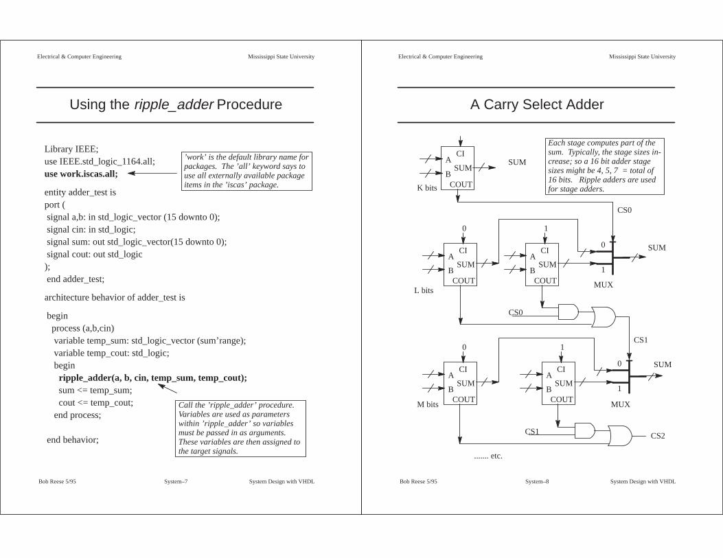
Using the ripple_adder Procedure
Library IEEE;use IEEE.std_logic_1164.all;use work.iscas.all;
entity adder_test isport ( signal a,b: in std_logic_vector (15 downto 0); signal cin: in std_logic; signal sum: out std_logic_vector(15 downto 0); signal cout: out std_logic); end adder_test;
architecture behavior of adder_test is
begin process (a,b,cin) variable temp_sum: std_logic_vector (sum’range); variable temp_cout: std_logic; begin ripple_adder(a, b, cin, temp_sum, temp_cout); sum <= temp_sum; cout <= temp_cout; end process; end behavior;
’work’ is the default library name forpackages. The ’all’ keyword says touse all externally available packageitems in the ’iscas’ package.
Call the ’ripple_adder’ procedure.Variables are used as parameterswithin ’ripple_adder’ so variablesmust be passed in as arguments.These variables are then assigned tothe target signals.
Mississippi State UniversityElectrical & Computer Engineering
System Design with VHDLSystem–8 Bob Reese 5/95
A Carry Select Adder
A
B
CI
COUT
SUM
A
B
CI
COUT
SUM
0
A
B
CI
COUT
SUM
1
0
1
MUX
CS0
CS0
A
B
CI
COUT
SUM
0
A
B
CI
COUT
SUM
1
0
1
MUX
CS1
CS1 CS2
....... etc.
K bits
L bits
M bits
SUM
SUM
SUM
Each stage computes part of thesum. Typically, the stage sizes in-crease; so a 16 bit adder stagesizes might be 4, 5, 7 = total of16 bits. Ripple adders are usedfor stage adders.

Mississippi State UniversityElectrical & Computer Engineering
System Design with VHDLSystem–9 Bob Reese 5/95
Carry_Select_Adder Procedure
procedure carry_select_adder (groups: iarray; a,b: in std_logic_vector; cin: in std_logic; sum: inout std_logic_vector; cout: out std_logic) is
variable low_index, high_index :integer; variable temp_sum_a, temp_sum_b : std_logic_vector(sum’range); variable carry_selects :std_logic_vector(groups’range); variable carry_zero :std_logic_vector(groups’low to (groups’high–1)); variable carry_one :std_logic_vector(groups’low to (groups’high–1));
begin low_index := 0; for i in groups’low to groups’high loop high_index := (groups(i)–1) + low_index ; if (i = 0) then –– first group, just do one ripple–carry
ripple_adder (a(high_index downto low_index), b(high_index downto low_index), cin, sum(high_index downto low_index), carry_selects(0) );
else–– need to do two ripple carry adders then use mux to select ripple_adder (a(high_index downto low_index), b(high_index downto low_index),
’0’, temp_sum_a(high_index downto low_index), carry_zero(i–1));
ripple_adder (a(high_index downto low_index), b(high_index downto low_index), ’1’, temp_sum_b(high_index downto low_index), carry_one(i–1));if (carry_selects(i–1) = ’0’) then
sum(high_index downto low_index) := temp_sum_a(high_index downto low_index); else sum(high_index downto low_index) := temp_sum_b(high_index downto low_index);
end if; carry_selects(i) := (carry_selects(i–1) and carry_one(i–1) ) or carry_zero(i–1); end if; low_index := high_index + 1; end loop; cout := carry_selects(groups’high); end ripple_adder;
Mississippi State UniversityElectrical & Computer Engineering
System Design with VHDLSystem–10 Bob Reese 5/95
iscas Package Declaration
Library IEEE;use IEEE.std_logic_1164.all;
package iscas is
type IARRAY is array (natural range <>) of integer;
procedure ripple_adder (a,b: in std_logic_vector; cin: in std_logic; sum: inout std_logic_vector; cout: out std_logic);
procedure carry_select_adder (groups: iarray; a,b: in std_logic_vector; cin: in std_logic;
sum: inout std_logic_vector; cout: out std_logic);end iscas;
⇒ We need to declare an array type for integers; call this IARRAY.
This type will be used to pass in an integer array to the carry_se-
lect_adder procedure; the integer array will be define the stage
sizes for the adder.
⇒ Since xor3 is to be local to the iscas package; it is not in the pack-
age declaration. However, if it was to be made externally avail-
able, its declaration would be:
function xor3 (a,b,c: in std_logic) return std_logic;

Mississippi State UniversityElectrical & Computer Engineering
System Design with VHDLSystem–11 Bob Reese 5/95
Using the carry_select_adder Procedure
Library IEEE;use IEEE.std_logic_1164.all;use work.iscas.all;
entity adder_cs isport ( signal a,b: in std_logic_vector (15 downto 0); signal cin: in std_logic; signal sum: out std_logic_vector(15 downto 0); signal cout: out std_logic); end adder_cs;
architecture behavior of adder_cs is
begin process (a,b,cin) variable temp_sum: std_logic_vector (sum’range); variable temp_cout: std_logic; constant groups: iarray(0 to 2) := (4,5,7);
begin carry_select_adder(groups,a,b,cin,temp_sum, temp_cout); sum <= temp_sum; cout <= temp_cout; end process; end behavior;
Define local constant array of in-tegers to define the stage sizes forthe adder. 4 + 5 + 7 = 16 bits.Must be a constant array so thatstage sizes are known at compiletime.
Mississippi State UniversityElectrical & Computer Engineering
System Design with VHDLSystem–12 Bob Reese 5/95
12
34
56
78
12
34
56
78
A B C D
A B C D
4
10
1
0
12
2 310
12 14
11
10
12
9
4
56
2
1
7
12
4
5
2
1
6
13
14
8
8
14
1
6
6
0
8
9
15
15
10
54893211510
3
12
15
14
14
1311
10
8
8
1113
9
5
7
7
3
15
2
3
8
0
4
2
3
9
1
13
14
8
01413121176
0
11
10
6
6
0
2
12
39
7
1
5
cin
a(15
:0)
a(15
:0)
n10
44
n10
38
n10
31
n10
24
n10
18
n10
11n1042
n10
27
a(4)
a(6)
a(1)
a(7)
a(11)
a(12)
a(12)
a(8)
a(13)
a(14)
b(1
5:0)
n10
16a(
6)n
1065
b(6
)su
m(6
)
b(7)
b(11)
n10
43
n10
40n
1039
n10
41
n99
3n
1034
n1035
sum
(7)
n10
33
a(7)
n10
37n
1036
b(7
)
n1029
n10
55n
1026
n1028
sum
(11)
n10
25
a(11
)n
1030
b(1
1)
a(12
)n
1063
b(1
2)n
1022
sum
(12)
n10
23
n10
20
n10
19b
(15:
0)n
1021
n10
57n
1013
n1015
sum
(13)
n10
12
a(13
)n
1017
b(1
3)n
1060
a(14
)
a(14
)b
(14)
n10
09su
m(1
4)b
(14)
n10
62n
1010
n10
61
n10
07n
1008
b(1
4)
a(9)
a(0)
sum
(0)
n10
05b
(0)
a(10
)b
(9)
b(1
0)
n1000
a(10
)su
m(1
0)n
1054
n97
6b
(10)
n10
01n
974
sum
(15:
0)n
975
b(4)
b(0
)n
1056
cin
b(1
2)n
973
n96
5b
(0)
a(0)
b(1
0)
n1058
n1059
a(10
)
n984
b(1
)a(
9)n
966
sum
(15)
a(1)
n10
47n
999
b(1
)n
1048
n98
3b
(2)
n98
5
a(2)
b(1
2)n
1014
a(1)
sum
(1)
b(1
3)n
991
b(2
)b
(3)
b(1
)n
967
a(2)
a(3)
a(2)
b(3
)n
988
n96
8b
(2)
sum
(2)
a(3)
a(3)
sum
(3)
n98
7
b(8
)b
(8)
b(3
)
a(8)
n96
2a(
5)n
1006
n10
49n
969
n99
6su
m(9
)n
964
b(8)
b(9
)a(
9)b
(6)
n10
52n
998
n97
2b
(5)
n1053
n994
n97
1
n1032
a(8)
n10
64su
m(8
)n
961
a(6)
n99
5
b(6
)a(
8)
n97
7n
1002
n98
0
n97
9n
981
n97
0su
m(4
)a(
4)n
1046
b(4
)
n1004
a(5)
b(5)
sum(15:0)
n10
03n
1051
n10
50su
m(5
)
n958
n10
45n
982
n99
2
n97
8
n997
n95
9n
960
n96
3
n98
6n
989
n99
0
b(1
5)n
957
a(15
)
cou
tco
ut
a(15
)
b(1
5)

Mississippi State UniversityElectrical & Computer Engineering
System Design with VHDLSystem–13 Bob Reese 5/95
VHDL Generic lists
Library IEEE;use IEEE.std_logic_1164.all;use work.iscas.all;
entity adder_test isgeneric ( N : integer := 16);port ( signal a,b: in std_logic_vector (N–1 downto 0); signal cin: in std_logic; signal sum: out std_logic_vector(N–1 downto 0); signal cout: out std_logic); end adder_test;
architecture behavior of adder_test is
begin process (a,b,cin) variable temp_sum: std_logic_vector (sum’range); variable temp_cout: std_logic; begin ripple_adder(a, b, cin, temp_sum, temp_cout); sum <= temp_sum; cout <= temp_cout; end process; end behavior;
Generic declaration whichis used to define thea,b,sum signal widths.
Default value is specifiedas 16.
Mississippi State UniversityElectrical & Computer Engineering
System Design with VHDLSystem–14 Bob Reese 5/95
VHDL Generic lists (cont.)
⇒ VHDL generic lists are used in entity declarations for passing stat-
ic information.
→ Typical uses of generics are for controlling bus widths, feature
inclusion, message generation, timing values.
⇒ A generic will usually have a specified default value; this value can
be overridden via VHDL configurations or by vendor–specific
back–annotation methods.
→ Generics offer a method for parameterizing entity
declarations and architectures. Because the method of
specifying generic values (other than defaults) can be
vendor specific, generics will not be covered further in this
tutorial.

Mississippi State UniversityElectrical & Computer Engineering
System Design with VHDLSystem–15 Bob Reese 5/95
Operator Overloading
Library IEEE; use IEEE.std_logic_1164.all;
package genmux is –– 2/1 version, 1 bit inputs function mux (a,b: std_logic; sel: std_logic) return std_logic; –– 2/1 version, N bit inputs function mux (a,b: std_logic_vector; sel: std_logic) return std_logic_vector;
–– 3/1 version, 1 bit inputs function mux (a,b,c: std_logic; sel: std_logic_vector) return std_logic; –– 3/1 version, N bit inputs function mux (a,b,c: std_logic_vector; sel: std_logic_vector) return std_logic_vector;
–– 4/1 version, 1 bit inputs function mux (a,b,c,d: std_logic; sel: std_logic_vector) return std_logic; –– 4/1 version, N bit inputs function mux (a,b,c,d: std_logic_vector; sel: std_logic_vector) return std_logic_vector;
end genmux;
package body genmux is function mux (a,b: std_logic; sel: std_logic) return std_logic is variable y: std_logic; begin y := a; if (sel = ’1’) then y := b; end if; return(y); end mux; –– 2/1 version, 1 bit inputs
function mux (a,b: std_logic_vector; sel: std_logic) return std_logic_vector is variable y: std_logic_vector(a’range); begin y := a; if (sel = ’1’) then y := b; end if; return(y); end mux; –– 2/1 version, N bit inputs
Mississippi State UniversityElectrical & Computer Engineering
System Design with VHDLSystem–16 Bob Reese 5/95
Operator Overloading (cont.)
function mux (a,b,c: std_logic; sel: std_logic_vector) return std_logic is variable y: std_logic; begin y := ’–’; –– Don’t care for default state if (sel = ”00”) then y := a; end if; if (sel = ”01”) then y := b; end if; if (sel = ”10”) then y := c; end if; return(y); end mux; –– 3/1 version, 1 bit inputs
function mux (a,b,c: std_logic_vector; sel: std_logic_vector) return std_logic_vector is variable y: std_logic_vector(a’range); begin y := (others => ’–’); –– Don’t care for default state if (sel = ”00”) then y := a; end if; if (sel = ”01”) then y := b; end if; if (sel = ”10”) then y := c; end if; return(y); end mux; –– 3/1 version, N bit inputs
function mux (a,b,c,d: std_logic; sel: std_logic_vector) return std_logic is variable y: std_logic; begin y := d; if (sel = ”00”) then y := a; end if; if (sel = ”01”) then y := b; end if; if (sel = ”10”) then y := c; end if; return(y); end mux; –– 4/1 version, 1 bit inputs
function mux (a,b,c,d: std_logic_vector; sel: std_logic_vector) return std_logic_vector is variable y: std_logic_vector(a’range); begin y := d; if (sel = ”00”) then y := a; end if; if (sel = ”01”) then y := b; end if; if (sel = ”10”) then y := c; end if; return(y); end mux; –– 4/1 version, N bit inputs
end genmux;

Mississippi State UniversityElectrical & Computer Engineering
System Design with VHDLSystem–17 Bob Reese 5/95
Test of ’mux’ Function
Library IEEE;use IEEE.std_logic_1164.all;use work.genmux.all;
entity muxtest isport ( signal a,b,c: in std_logic; signal s_a: in std_logic_vector(1 downto 0); signal y: out std_logic; signal j,k,l: in std_logic_vector(3 downto 0); signal s_b: in std_logic_vector(1 downto 0); signal z: out std_logic_vector(3 downto 0)); end muxtest;
architecture behavior of muxtest is
begin
y <= mux (a,b,c,s_a); z <= mux (j,k,l,s_b); end behavior;
The mux operator is overloaded; thecorrect mux function is chosen bydoing template matching on the pa-rameter lists.
Mississippi State UniversityElectrical & Computer Engineering
System Design with VHDLSystem–18 Bob Reese 5/95
12
34
56
78
12
34
56
78
A B C D
A B C D
3210
1
0 0
1
0 0
310 2
1 20 3
3210
s_a(
1:0)
s_a(
1:0)
k(3:
0)k(
3:0)
j(3:
0)j(
3:0)
l(3:
0)l(
3:0)
b ab
an
164
yy
cc
s_a(
1)n
157
s_a(
0)
s_a(
0)
n15
9n
158
k(0)
n16
0
j(0)
n15
5z(
0)
l(0)
n15
6
k(1)
j(1)
n15
3z(
1)
l(1)
n15
4
z(3:
0)k(
2)
j(2)
n15
1z(
2)
l(2)
n15
2
k(3)
s_b
(1:0
)
n162
z(3:0)
j(3)
s_b
(1:0
)s_
b(0
)n
149
z(3)
s_b
(1)
l(3)
n15
0n
161
n16
3s_
b(0
)

Mississippi State UniversityElectrical & Computer Engineering
System Design with VHDLSystem–19 Bob Reese 5/95
BlackJack Dealer
⇒ This example will be a BlackJack Dealer circuit (example taken
from The Art of Digital Design, Prosser & Winkel, Prentice–Hall).
⇒ One VHDL model will be written for the control and one for the da-
tapath. A schematic will be used to tie these two blocks together.
→ Later, a VHDL structural model will be used to connect the
blocks.
⇒ Control:
→ Four States:
Get –– get a card
Add –– add current card to score
Use –– use an ACE card as 11
Test –– see if we should stand or if we are broke
⇒ Datapath:
→ 5–bit register for loading score; needs a synchronous clear.
→ Mux for choosing between card value, plus 10 and minus 10.
→ Adder for adding card with current score.
→ ACE card detect (an ACE card has value ’0001’)
→ Comparator logic for checking is score is greater than 16 or
greater than 21.
Mississippi State UniversityElectrical & Computer Engineering
System Design with VHDLSystem–20 Bob Reese 5/95
BlackJack Dealer Control
GET
card.rdy.sync
MUX: Select Card REG: Load score
T→hit
ADD
BlackJack Dealer
F
card.rdy.delay
F
F→stand.outF→broke.out
REG: Clear scoreF→ace11flag.out
acecard ace11flag USE
MUX: Select ADD10REG: Load scoreT→ace11flag.out
T
T
T
F
stand +broke
T
T
F
F
To TEST state
Use ACE as 11
Start game over
Add card value
wait for card
wait until button
is lifted

Mississippi State UniversityElectrical & Computer Engineering
System Design with VHDLSystem–21 Bob Reese 5/95
BlackJack Dealer Control (cont)
TEST
score16gt
score21gt
F
T→stand.out
T
Tace11flag
MUX: Select SUB10REG: Load scoreF→ace11flag.out
F
T→broke.out
F
T
T
To GET state
Cancel ACE=11
Score is > 16 and< 21 so stand
Score > 21 and wecan’t adjust anACE value so weare broke
Mississippi State UniversityElectrical & Computer Engineering
System Design with VHDLSystem–22 Bob Reese 5/95
BlackJack Datapath
Car
d S
witc
hes MUX
5+10
5–10
54
Ace Finderacecard
2
sel
ADDER Score
REG
clear
5
5
5
5
5
Comparatorscore16gt
score21gtMiscellanous Flip Flops to be included in Control
stand.out stand
broke.out broke
ace11flag.outace11flag
CardRdy button
card.rdy.sync
card.rdy.delay
score
load

Mississippi State UniversityElectrical & Computer Engineering
System Design with VHDLSystem–23 Bob Reese 5/95
VHDL File for BlackJack Datapath
entity bjdpath is port ( signal clk,reset_b, load, clear_b: in std_logic; signal sel: in std_logic_vector(1 downto 0); signal card: in std_logic_vector(3 downto 0); signal acecard,score16gt,score21gt: out std_logic; signal score: out std_logic_vector(4 downto 0));end bjdpath;
architecture behavior of bjdpath issignal adder_out, score_in: std_logic_vector(4 downto 0)mux_out, score_out : std_logic_vector(4 downto 0);–– temporary signal for carriessignal c: std_logic_vector (5 downto 0);
beginscore_state: process(clk, reset_b)beginif (reset_b = ’0’) then score_out <= ”00000”;elsif (clk’event and clk = ’1’) THEN score_out <= score_in; END IF;end process score_state;
–– combinational logic for score registerscore_in <= ”00000” when (clear_b = ’0’) else
adder_out when (load = ’1’) else score_out;
State process forscore register flip–flops.
Combinational logicfor Score Register
Mississippi State UniversityElectrical & Computer Engineering
System Design with VHDLSystem–24 Bob Reese 5/95
VHDL File for BlackJack Datapath (cont.)
–– adder process–– adder_out <= score_out + mux_outadder:process (score_out, mux_out) begin c(0) <= ’0’; for i in score_out’range loop adder_out(i) <= score_out(i) xor mux_out(i) xor c(i); c(i+1) <= (score_out(i) and mux_out(i)) or
(c(i) and (score_out(i) or mux_out(i))); end loop;end process adder;
mux_out <= ”01010” when (sel = B”00”) else ”10110” when (sel = B”10”) else ’0’ & card;
acecard <= ’1’ when (card = B”0001”) else ’0’;
score <= score_out;
score16gt <= ’1’ when (score_out > B”10000”) else ’0’;score21gt <= ’1’ when (score_out > B”10101”) else ’0’; end behavior;
MUX forcard, plus 10,minus 10.
ADDER process
Ace Finder
Comparators

Mississippi State UniversityElectrical & Computer Engineering
System Design with VHDLSystem–25 Bob Reese 5/95
VHDL File for BlackJack Control
entity bjcontrol is port ( signal clk, reset_b, card_rdy, acecard: in std_logic; signal score16gt, score21gt: in std_logic; signal hit, broke, stand: out std_logic; signal sel: out std_logic_vector(1 downto 0); signal score_clear_b, score_load: out std_logic); end bjcontrol;
architecture behavior of bjcontrol is
–– declare internal signals here signal n_state, p_state : std_logic_vector(1 downto 0);signal ace11flag_pstate, ace11flag_nstate: std_logic;signal broke_pstate, broke_nstate: std_logic;signal stand_pstate, stand_nstate: std_logic;signal card_rdy_dly, card_rdy_sync: std_logic;
–– state assignments are as followsconstant get_state: std_logic_vector(1 downto 0) := B”00”;constant add_state: std_logic_vector(1 downto 0) := B”01”;constant test_state: std_logic_vector(1 downto 0) := B”10”;constant use_state: std_logic_vector(1 downto 0) := B”11”;
constant add_10_plus: std_logic_vector(1 downto 0) := B”00”;constant add_card: std_logic_vector(1 downto 0) := B”01”;constant add_10_minus: std_logic_vector(1 downto 0) := B”10”;
Entity declarationand State Assignments
Mississippi State UniversityElectrical & Computer Engineering
System Design with VHDLSystem–26 Bob Reese 5/95
VHDL File for BlackJack Control (cont.)
begin –– state process to implement flag flip–flops and FSM statestate: process(clk, reset_b)beginif (reset_b = ’0’) then p_state <= ”00”;elsif (clk’event and clk = ’1’) THEN p_state <= n_state; ace11flag_pstate <= ace11flag_nstate; broke_pstate <= broke_nstate; stand_pstate <= stand_nstate; card_rdy_dly <= card_rdy_sync; card_rdy_sync <= card_rdy; END IF;end process state;
broke <= broke_pstate;stand <= stand_pstate;
State process to define flip–flops for various flags andfinite state machine .

Mississippi State UniversityElectrical & Computer Engineering
System Design with VHDLSystem–27 Bob Reese 5/95
VHDL File for BlackJack Control (cont.)
comb: process (p_state, ace11flag_pstate, broke_pstate, stand_pstate, acecard, card_rdy_dly, card_rdy_sync, score16gt, score21gt)
beginsel <= B”00”;score_load <= ’0’; score_clear_b <= ’1’;hit <= ’0’; n_state <= p_state;ace11flag_nstate <= ace11flag_pstate;stand_nstate <= stand_pstate; broke_nstate <= broke_pstate;
case p_state is when get_state =>
if (card_rdy_sync = ’0’) then hit <= ’1’; elsif (card_rdy_dly = ’0’) then
stand_nstate <= ’0’; broke_nstate <= ’0’; if (stand_pstate = ’1’ or broke_pstate = ’1’) then score_clear_b <= ’0’; ace11flag_nstate <= ’0’; end if; n_state <= add_state;end if;
when add_state =>sel <= add_card; score_load <= ’1’;if (acecard = ’1’ and ace11flag_pstate = ’0’) then n_state <= use_state;else n_state <= test_state;end if;
’get’ and ’add’states
Mississippi State UniversityElectrical & Computer Engineering
System Design with VHDLSystem–28 Bob Reese 5/95
VHDL File for BlackJack Control (cont.)
when use_state =>
sel <= add_10_plus;score_load <= ’1’;ace11flag_nstate <= ’1’;
n_state <= test_state;
when test_state =>
if (score16gt = ’0’) then n_state <= get_state;
elsif (score21gt = ’0’) then stand_nstate <= ’1’;
n_state <= get_state;elsif (ace11flag_pstate = ’0’) then broke_nstate <= ’1’;
n_state <= get_state;else sel <= add_10_minus; score_load <= ’1’; ace11flag_nstate <= ’0’;end if;
when OTHERS => n_state <= p_state;
end case;end process comb;end behavior;
’use’ and’test’ states

Mississippi State UniversityElectrical & Computer Engineering
System Design with VHDLSystem–29 Bob Reese 5/95
Top Level Schematic for Dealer
Mississippi State UniversityElectrical & Computer Engineering
System Design with VHDLSystem–30 Bob Reese 5/95
Blackjack Dealer Simulation
Initial Scoreof zero
Enter ’5’ Card Enter ’8’ Card Enter ’4’ Card
Score = 5 + 0 = 5
Score = 8 + 5 = 13
Score = 13 + 4 = 17; score is > 16 so we STAND.

Mississippi State UniversityElectrical & Computer Engineering
System Design with VHDLSystem–31 Bob Reese 5/95
Blackjack Dealer Simulation (cont.)
Assertion ofSTAND fromprevious gamecauses us tostart newgame.
First card is an’Ace’.
Next card is a ’2’
Next card is a ’9’
We will use thefirst ’Ace’ as a val-ue of ’11’.
Score = 11 + 2 = 13
13 + 9 > 21 so we break;however, we have an ’Ace’so we can treat it as a val-ue of ’1’; the new score is:1 + 2 + 9 = 12.
Final cardis a ’10’(facecard)
12 + 10 > 21 so weare ’BROKE’.
Mississippi State UniversityElectrical & Computer Engineering
System Design with VHDLSystem–32 Bob Reese 5/95
Structural VHDL
⇒ You do not have to use a schematic to connect VHDL blocks. You
can write a structural VHDL model which ties the blocks together.
⇒ Pros:
→ When you synthesize the design all of the VHDL blocks are
flattened (collapsed into one block) and it is possible that the
resulting logic may be more efficient.
→ The structural VHDL code is more portable to other design
systems than a schematic.
⇒ Cons:
→ Writing structural VHDL code can be more error prone than
creating a schematic (very easy to misplace a net when you
don’t have a ’picture’ to go by).
→ The resulting flattened netlist can be more difficult to debug.

Mississippi State UniversityElectrical & Computer Engineering
System Design with VHDLSystem–33 Bob Reese 5/95
Structural VHDL for BlackJack Player
entity bj_struct is port ( signal reset_b, clk, card_rdy : in std_logic; signal card: in std_logic_vector(3 downto 0); signal stand, broke,hit: out std_logic; signal score: out std_logic_vector(4 downto 0) );end bj_struct;
architecture structure of bj_struct is component bjcontrol port ( signal clk,reset_b: in std_logic; signal card_rdy, acecard: in std_logic; signal score16gt, score21gt: in std_logic; signal hit, broke,stand: out std_logic; signal sel: out std_logic_vector(1 downto 0); signal score_clear_b: out std_logic; signal score_load: out std_logic ); end component;
component bjdpath port ( signal clk, reset_b: in std_logic; signal load, clear_b: in std_logic; signal sel: in std_logic_vector(1 downto 0); signal card: in std_logic_vector(3 downto 0); signal acecard, score16gt: out std_logic; signal score21gt: out std_logic; signal score: out std_logic_vector(4 downto 0) );
end component;
Need a component dec-laration for each differ-ent type of componentused in the schematic
Normal entitydeclaration.
Mississippi State UniversityElectrical & Computer Engineering
System Design with VHDLSystem–34 Bob Reese 5/95
Structural VHDL for BlackJack Player (cont)
signal load_net, clear_net, acecard_net : std_logic; signal sel_net : std_logic_vector (1 downto 0); signal s21gt_net, s16gt_net: std_logic;
begin c1: bjcontrol port map ( clk => clk,
reset_b => reset_b,card_rdy => card_rdy, acecard => acecard_net,score16gt => s16gt_net,score21gt => s21gt_net,hit => hit, broke => broke, stand => stand,sel => sel_net,score_clear_b => clear_net,score_load => load_net);
c2: bjdpath port map ( clk => clk,
reset_b => reset_b,load => load_net,clear_b => clear_net,
sel => sel_net, card => card, acecard => acecard_net,
score16gt => s16gt_net,score21gt => s21gt_net,
score => score );
end structure;
Internal signal declara-tion for those nets notconnected to externalports.
Each component used in thedesign is given along withits port map.
’c1’ is the component label,’bjcontrol’ gives the compo-nent type.
Only two components inthis design.

Mississippi State UniversityElectrical & Computer Engineering
System Design with VHDLSystem–35 Bob Reese 5/95
Results of bj_struct Synthesis