lmca linear motors
TRANSCRIPT

LMCA
LINEAR MOTORS

About Us
UNIMOTION is a leading company in the industrial automation field, at a global level. Combining innovative engineering solutions – Unimotion helps companies of all sizes across a wide range of industrial segments. Unimotion develops Industry 4.0-enabled products and systems with leading quality, performance and value. Engineering, Production, Construction, Warehouse, Research & Development department; all this can be found under one roof. Thanks to years of experience and a consistent focus on automation technology, we are continually improving our products and implementing innovations that provide customers with many technical advantages. Our core values are precision, innovation, passion, and integrity. At Unimotion, our main goal is the satisfaction of every single customer with a commitment to deliver the impossible.
Unimotion sales team, technicians and experts are at your disposal to provide customized expertise and support. We look forward to meeting you and work on your special project.

In order to improve the products in this catalogue the specifications are subject to change without notice.
Table of Contents
LMCA Hall effect sensor 26
Characteristics 12
Product overview 4
Basic description 6
Structural design ............................................................................................................................................................................................................................... 8Terms explanation ............................................................................................................................................................................................................................. 9
How to order 10
Selection example 29
LMCA 30 .......................................................................................................................................................................................................................................... 13LMCA 60 .......................................................................................................................................................................................................................................... 16LMCA 90 .......................................................................................................................................................................................................................................... 19Mounting tolerances ....................................................................................................................................................................................................................... 22Electrical data .................................................................................................................................................................................................................................. 23
3

Product overview

LMCA PRODUCT OVERVIEW
In order to improve the products in this catalogue the specifications are subject to change without notice.
LMCA 30 is our smallest design in the LMCA family. In the picture LMCA 30 S is presented. It is also available in M and L versions.
They offer a superb ratio between maximum velocity and the mass of the forcer, therefore they are suitable for applications with light payloads, where high speeds and accelera-tions are required.
LMCA 60 represents the middle section of the LMCA family. In the picture LMCA 60 M is presented. It is also available in S, L and XL versions.
Because of their mid-range design, they offer high dynamics and a great speed-to-force ra-tio.
LMCA 90 is our strongest design in the LMCA family. In the picture LMCA 90 XL is presented. It is also available in S, M and L versions.
They are primarily used in applications where axial force demands are the highest.
LMCA 30
FC
FP
FU
LMCA 60
FC
FP
FU
LMCA 90
FC
FP
FU
100 N 1000 N 10.000 N
141–465 N
282–1237 N
424–1856 N
311–1056 N
621–2810 N
932–4215 N
391–1358 N
783–3613 N
1174–5419 N
FC = Continuous Force
FP = Peak Force
FU = Ultimate Force
PRODUCT OVERVIEW
POWER RANGE
5

Basic description
Structural design ............................................................................................................................................................................................................................... 8
Terms explanation ............................................................................................................................................................................................................................ 9

Linear motors are an ideal substitute for pneumatic, hydraulic, belt, ball screw, or other types of drives. Linear motor drive systems do not require conversion from rotational to linear movement, because the movement is generated directly from the linear electromagnetic force. The linear motor driven systems in comparison with the traditional linear units are more compact, accurate, repeatable, faster, robust, reliable, generate less noise and after all, require no maintenance. Linear motors are also known as “direct-drive” motors because the load is directly coupled onto them.
• UNIMOTION linear motors are ideal for a variety of applications, ie.: actuators, robots, XYZ tables, po-sitioning, assembly, tool machines, P&P machines, fiber optic machines, and many others. The main advantage of UNIMOTION linear motors is force density, which is 30–50 % higher compared to other competitors on the market, while still retaining a very low cogging force. Thanks to our innovative design and state-of-the-art materials, we can offer our customers the industry-leading linear motor on the market for a competitive price.
Besides different motor sizes (30, 60, 90) and versions (S, M, L and XL), we offer two types of magnet plates that are compatible with all the motors:
– A classic magnet plate, that enables continuous forces from 141 N to 1665 N (peak from 311 N to 3661 N), and
– Our innovative high-performance magnet plate design, which results in much higher force density and also boosts the continuous (from 158 N to 1856 N) and peak forces (from 358 N to 4215 N), which is nearly 11 % higher in comparison with the classic magnet plate.
Additionally, for each motor size, we are offering two speed types:
– A low-speed variant, and– A high-speed variant, which has a lower BEMF constant and is suitable for applications, requiring
higher speed or low supply voltage.
Both solutions are air-cooled with an extremely high force density, which offers a small and very compact design of the linear motion systems and units.
In order to allow an easy drive integration, we designed our own Hall module which features analog as well as a digital Hall sensor in only one housing.
For more information regarding the Hall sensor, please refer to page 27–28.
7
LMCA LINEAR MOTORS BASIC DESCRIPTION / STRUCTURAL DESIGN
In order to improve the products in this catalogue the specifications are subject to change without notice.

STRUCTURAL DESIGN
1 – Hole for the centering ring
2 – Forcer body
3 – Power cable
4 – Signal cable
5 – Hall sensor mounting holes
6 – Mounting holes
7 – Magnet plate
For more information regarding the Hall sensor, please refer to page 27–28.
54 3 6 2 1
7
8 In order to improve the products in this catalogue the specifications are subject to change without notice.
LMCA LINEAR MOTORS BASIC DESCRIPTION / STRUCTURAL DESIGN

TERMS EXPLANATION
Supply voltage VDC: A maximum allowed supply voltage, that can be applied to the motor windings.
Continuous force FC: Force produced by the continuous current (IC) at an ambient temperature of 20 °C and continuous movement of the motor. The windings temperature depends on the attached plate (heatsink) heat dissipation and airflow around the motor.
Peak force FP:Force produced by the peak current (IP) for a duration of 1 second. The force is used for acceleration or deceleration.
Ultimate force FU:Force produced by the ultimate current (IU) for a duration of 0,5 seconds. The force is used for acceleration or deceleration.
Attraction force of magnets FA:Attraction force between the forcer and the magnet plate at the defined air gap.
Cogging (detent) force FG:Force generated due to the interaction between the permanent magnets of the magnet plate and the mover slots. The cogging force is permanently present and is position-dependent.
Force constant KF:Defines how much force is produced per unit of current. It is the ratio of the force to the motor phase current.
Motor constant KM:The ratio of the motor force and square root of the power loss at 20 °C. The constant determines the motor's efficiency.
Back EMF phase-phase constant KBEMF: Defines the phase-to-phase voltage generated when the motor is moving at 1 m/s at the magnet temperature of 20 °C.
Continuous current IC:It corresponds to the continuous force (FC) and can be continuously applied to the motor at the ambient temperature of 20 °C and continuous movement of the motor. The windings temperature depends on the attached plate (heatsink) heat dissipation and airflow around the motor.
Peak current IP:Corresponds to the peak force (FP) and can be applied to the motor for 1 second.
Ultimate current IU:Corresponds to the ultimate force (FU) and can be applied to the motor for 0,5 seconds.
Resistance phase-phase R20:Motor windings resistance measured phase to phase (line to line) at 20 °C.
Resistance phase-phase R125:Motor windings resistance measured phase to phase (line to line) at 125 °C.
Induction phase-phase LP:Motor windings inductance measured phase-to-phase (line-to-line).
Electrical time constant tC:The electrical time constant is the amount of time it takes for the current in the motor windings to reach 63 % of its rated value. The time constant is found by dividing inductance by resistance.
Max. winding temperature Tmax:Defined as a maximum permissible temperature of the motor windings. During the normal operation, it is recommended that windings temperature does not exceed 80 % of Tmax.
Thermal resistance Rth:Defines the heat transfer resistance from the motor windings to the environment at the defined plate (heatsink) and air dissipation.
Thermal resistance to heatsink Rth-HS:Defines the heat transfer resistance from the motor windings to the heatsink attached surface.
Magnet pitch τ:Magnet pitch or pole pair length is the distance between two same polar magnets on the magnet plate.
Thermal time constant τth:
Defined as a time required for the winding to reach 63% of the max. temperature at continuous current. This value is only applicable when the mounting surface is at the constant temperature.
Forc
e [%
]
Air gap [mm]
60
70
80
90
100
110
120
1,51,20,90,6
FA
FC
Continuous and attraction force as a function of an air gap Described parameters were measured with an air gap of 0,6 mm.
An actual air gap between the magnet plate and coil unit is difficult to measure because of the casted finish. For an accurate measurement, the air gap can be calculated from the total mounting height. The air gap of 0,6 mm provides an optimal
continuous-to-attraction force ratio. Increasing the air gap will result in a lower attraction force, lower cogging and lower useful force.
9In order to improve the products in this catalogue the specifications are subject to change without notice.
LMCA LINEAR MOTORS BASIC DESCRIPTION / TERMS EXPLANATION

How to order

HOW TO ORDER
LMCA MPA HM 18060 60
Series:LMCA
Series:MPA
Size:– 30– 60– 90
Size:– 30– 60– 90
Version:– S– M– L– XL
Length:– 120– 180– 300
Type:– L: Low speed– H: High speed
Type:– C: Classic– H: High performance
XL version is only available for sizes 60 and 90.
Forcer order code: Magnet plate order code:
CALCULATE AND CONFIGURE YOUR OWN SOLUTION
The LINEAR MOTOR CALCULATION TOOL is an online application that enables quick and easy selection of a suitable product, with the possibility of achieving the optimal ratio between the given capacity and the price and the creation of the 3D models.
For more information please contact us or visit our website.
L
11In order to improve the products in this catalogue the specifications are subject to change without notice.
LMCA HOW TO ORDER

CharacteristicsLMCA 30 ....................................................................................................................................................................................................................... 13
LMCA 60 ....................................................................................................................................................................................................................... 16
LMCA 90 ....................................................................................................................................................................................................................... 19
Mounting tolerances ..................................................................................................................................................................................................... 22
Electrical data ............................................................................................................................................................................................................... 23

LMCA LINEAR MOTOR CHARACTERISTICS / LMCA 30
LMCA 30
General technical data
LMCA 30Version S Version M Version L
Classic High performance Classic High
performance Classic High performance
PARAMETER SYM UNIT Low speed
High speed
Low speed
High speed
Low speed
High speed
Low speed
High speed
Low speed
High speed
Low speed
High speed
PERF
ORM
ANCE
Max. supply voltage VDC V (DC) 600Continuous force1 FC N 141 158 279 311 417 465Peak force (1s)1 FP N 311 358 614 707 917 1056Ultimate force (0,5s)1 FU N 391 460 773 909 1155 1358Attraction force of magnets2 FA N 678 958 1245 1759 1812 2560
Force constant KFN
ARMS47,0 20,5 52,7 23,0 46,5 20,4 51,8 22,7 46,3 20,2 51,7 22,6
Motor constant KMN
√W 17,2 17,2 19,3 19,3 24,1 24,0 26,8 26,8 29,4 29,2 32,7 32,6
Back EMF phase-phase constant KBEMF
VRMS(m/s) 27,2 11,9 31,4 13,7 26,9 11,7 31,0 13,5 26,7 11,7 30,9 13,5
ELEC
TRIC
AL
Continuous current IC ARMS 3,0 6,9 3,0 6,9 6,0 13,7 6,0 13,7 9,0 20,6 9,0 20,6Peak current IP ARMS 9,0 20,6 9,0 20,6 18,0 41,2 18,0 41,2 27,0 61,8 27,0 61,8Ultimate current IU ARMS 15,0 34,3 15,0 34,3 30,0 68,7 30,0 68,7 45,0 103,0 45,0 103,0Resistance at 20 °C phase-phase R20 Ω 4,99 0,95 4,99 0,95 2,49 0,48 2,49 0,48 1,66 0,32 1,66 0,32
Resistance at 125 °C phase-phase R125 Ω 7,05 1,34 7,05 1,34 3,52 0,68 3,52 0,68 2,34 0,45 2,34 0,45
Induction phase-phase LP mH 28,2 5,4 28,2 5,4 14,1 2,7 14,1 2,7 9,4 1,8 9,4 1,8
Electrical time constant3 tC mS 5,7 5,7 5,7 5,7 5,7 5,6 5,7 5,6 5,7 5,6 5,7 5,6
THER
MAL
Max. winding temperature Tmax °C 125
Max. allowed magnet plate temperature
Tmagnet °C 90
Thermal time constant τth s 69
Thermal resistance RthKW
1,10 0,55 0,37
Thermal resistance to heatsink Rth_HS
KW
0,250 0,125 0,083
MEC
HAN
ICAL
Forcer overall length ML mm 128 233 338Forcer overall width MW mm 56Forcer overall height MH mm 23,5Forcer mass mm kg 0,8 1,5 2,2
Magnet plate weight mSkgm 2,4 2,6 2,4 2,6 2,4 2,6
Forcer wires cross-section SC mm2 1,5 2,5 1,5 2,5
Sensor wires cross-section SSC mm2 0,25
Forcer cable length LM mm 1000Sensor cable length LS mm 1000Magnet pitch τ mm 30
1 Magnets at 20 °C2 RMS at 0 A and air gap of 0,6 mm3 Windings at 20 °C
The specifications were measured without forced cooling. Electrical specifications tolerance is ± 10 %.
13In order to improve the products in this catalogue the specifications are subject to change without notice.

LMCA LINEAR MOTOR CHARACTERISTICS / LMCA 30
Force as a function of velocity diagrams
Bus voltage = 325 V DC Bus voltage = 560 V DC
Forc
e [N]
Velocity [m/s]
0
100
200
300
400
181614121086420
Peak ForceCont. Force
LMCA 30 S H HLMCA 30 S L HLMCA 30 S H C LMCA 30 S L C
Forc
e [N]
Velocity [m/s] 302520151050
0
100
200
300
400Peak ForceCont. Force
LMCA 30 S H HLMCA 30 S L HLMCA 30 S H C LMCA 30 S L C
181614121086420
Forc
e [N]
Velocity [m/s]
0
200
400
600
800Peak ForceCont. Force
LMCA 30 M H HLMCA 30 M L HLMCA 30 M H C LMCA 30 M L C
0
200
400
600
800
Forc
e [N]
Velocity [m/s] 302520151050
Peak ForceCont. Force
LMCA 30 M H HLMCA 30 M L HLMCA 30 M H C LMCA 30 M L C
Forc
e [N]
Velocity [m/s]
0
300
600
900
1200
181614121086420
Peak ForceCont. Force
LMCA 30 L H HLMCA 30 L L HLMCA 30 L H C LMCA 30 L L C
0
300
600
900
1200
Forc
e [N]
Velocity [m/s] 302520151050
Peak ForceCont. Force
LMCA 30 L H HLMCA 30 L L HLMCA 30 L H C LMCA 30 L L C
14 In order to improve the products in this catalogue the specifications are subject to change without notice.

LMCA LINEAR MOTOR CHARACTERISTICS / LMCA 30
Forcer dimensionsForcer dimensions
Magnet plate dimensions
All dimensions are in mm. The scale of the drawings may not be equal.* Standard cable length
** The stated mounting height is set for the air gap of 0,6 mm. For more information, please refer to page 9.
LMCA 30 L1 [mm] L2 ± 0,02 [mm] N ØC LC [mm]LMCA 30 S H/L 128 108 3 9,1 1000LMCA 30 M H/L 233 213 6 9,1 1000LMCA 30 L L 338 318 9 9,1 1000LMCA 30 L H 338 318 9 10,6 1000
MPA 30 L1 [mm] L2 [mm] NMPA 30 120 C/H 120 124,2 2MPA 30 180 C/H 180 184,2 3MPA 30 300 C/H 300 304,2 5
* The stated mounting height is set for the air gap of 0,6 mm. For more information, please refer to page 9.
'N' is the number of mounting holes in the x-direction.
'N' is the number of mounting slots in the x-direction.
Positive motor direction
15In order to improve the products in this catalogue the specifications are subject to change without notice.
LMCA LINEAR MOTOR CHARACTERISTICS / LMCA 60
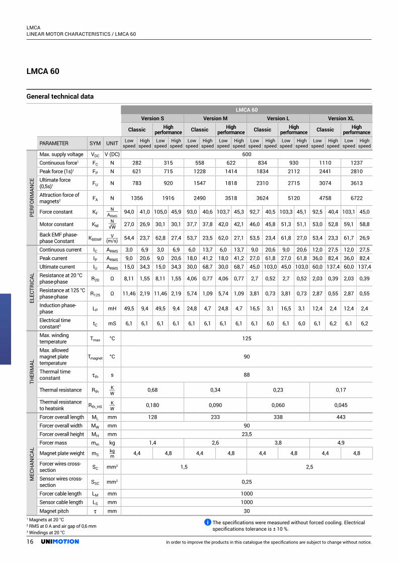
LMCA 60
General technical data
LMCA 60Version S Version M Version L Version XL
Classic High performance Classic High
performance Classic High performance Classic High
performance
PARAMETER SYM UNIT Low speed
High speed
Low speed
High speed
Low speed
High speed
Low speed
High speed
Low speed
High speed
Low speed
High speed
Low speed
High speed
Low speed
High speed
PERF
ORM
ANCE
Max. supply voltage VDC V (DC) 600Continuous force1 FC N 282 315 558 622 834 930 1110 1237Peak force (1s)1 FP N 621 715 1228 1414 1834 2112 2441 2810Ultimate force (0,5s)1 FU N 783 920 1547 1818 2310 2715 3074 3613
Attraction force of magnets2 FA N 1356 1916 2490 3518 3624 5120 4758 6722
Force constant KFN
ARMS94,0 41,0 105,0 45,9 93,0 40,6 103,7 45,3 92,7 40,5 103,3 45,1 92,5 40,4 103,1 45,0
Motor constant KMN
√W 27,0 26,9 30,1 30,1 37,7 37,8 42,0 42,1 46,0 45,8 51,3 51,1 53,0 52,8 59,1 58,8
Back EMF phase-phase Constant KBEMF
V(m/s) 54,4 23,7 62,8 27,4 53,7 23,5 62,0 27,1 53,5 23,4 61,8 27,0 53,4 23,3 61,7 26,9
ELEC
TRIC
AL
Continuous current IC ARMS 3,0 6,9 3,0 6,9 6,0 13,7 6,0 13,7 9,0 20,6 9,0 20,6 12,0 27,5 12,0 27,5Peak current IP ARMS 9,0 20,6 9,0 20,6 18,0 41,2 18,0 41,2 27,0 61,8 27,0 61,8 36,0 82,4 36,0 82,4Ultimate current IU ARMS 15,0 34,3 15,0 34,3 30,0 68,7 30,0 68,7 45,0 103,0 45,0 103,0 60,0 137,4 60,0 137,4Resistance at 20 °C phase-phase R20 Ω 8,11 1,55 8,11 1,55 4,06 0,77 4,06 0,77 2,7 0,52 2,7 0,52 2,03 0,39 2,03 0,39
Resistance at 125 °C phase-phase R125 Ω 11,46 2,19 11,46 2,19 5,74 1,09 5,74 1,09 3,81 0,73 3,81 0,73 2,87 0,55 2,87 0,55
Induction phase-phase LP mH 49,5 9,4 49,5 9,4 24,8 4,7 24,8 4,7 16,5 3,1 16,5 3,1 12,4 2,4 12,4 2,4
Electrical time constant3 tC mS 6,1 6,1 6,1 6,1 6,1 6,1 6,1 6,1 6,1 6,0 6,1 6,0 6,1 6,2 6,1 6,2
THER
MAL
Max. winding temperature Tmax °C 125
Max. allowed magnet plate temperature
Tmagnet °C 90
Thermal time constant τth s 88
Thermal resistance RthKW
0,68 0,34 0,23 0,17
Thermal resistance to heatsink Rth_HS
KW
0,180 0,090 0,060 0,045
MEC
HAN
ICAL
Forcer overall length ML mm 128 233 338 443Forcer overall width MW mm 90Forcer overall height MH mm 23,5Forcer mass mm kg 1,4 2,6 3,8 4,9
Magnet plate weight mSkgm 4,4 4,8 4,4 4,8 4,4 4,8 4,4 4,8
Forcer wires cross-section SC mm2 1,5 2,5
Sensor wires cross-section SSC mm2 0,25
Forcer cable length LM mm 1000Sensor cable length LS mm 1000Magnet pitch τ mm 30
1 Magnets at 20 °C2 RMS at 0 A and air gap of 0,6 mm3 Windings at 20 °C
The specifications were measured without forced cooling. Electrical specifications tolerance is ± 10 %.
16 In order to improve the products in this catalogue the specifications are subject to change without notice.

LMCA LINEAR MOTOR CHARACTERISTICS / LMCA 60
Forc
e [N]
Velocity [m/s] 1086420
0
200
400
600
800Peak ForceCont. Force
LMCA 60 S H HLMCA 60 S L HLMCA 60 S H C LMCA 60 S L C
Forc
e [N]
Velocity [m/s] 1086420
0
400
800
1200
1600Peak ForceCont. Force
LMCA 60 M H HLMCA 60 M L HLMCA 60 M H C LMCA 60 M L C
Forc
e [N]
Velocity [m/s]
0
500
1000
1500
2000
2500
1086420
Peak ForceCont. Force
LMCA 60 L H HLMCA 60 L L HLMCA 60 L H C LMCA 60 L L C
Forc
e [N]
Velocity [m/s]
0
500
1000
1500
2000
2500
3000
3500
1086420
Peak ForceCont. Force
LMCA 60 XL H HLMCA 60 XL L HLMCA 60 XL H C LMCA 60 XL L C
Forc
e [N]
Velocity [m/s] 1614121086420
0
200
400
600
800Peak ForceCont. Force
LMCA 60 S H HLMCA 60 S L HLMCA 60 S H C LMCA 60 S L C
Forc
e [N]
Velocity [m/s] 1614121086420
0
400
800
1200
1600Peak ForceCont. Force
LMCA 60 M H HLMCA 60 M L HLMCA 60 M H C LMCA 60 M L C
0
500
1000
1500
2000
2500
Forc
e [N]
Velocity [m/s] 1614121086420
Peak ForceCont. Force
LMCA 60 L H HLMCA 60 L L HLMCA 60 L H C LMCA 60 L L C
Forc
e [N]
Velocity [m/s] 1614121086420
0
500
1000
1500
2000
2500
3000
3500Peak ForceCont. Force
LMCA 60 XL H HLMCA 60 XL L HLMCA 60 XL H C LMCA 60 XL L C
Force as a function of velocity diagrams
Bus voltage = 325 V DC Bus voltage = 560 V DC
17In order to improve the products in this catalogue the specifications are subject to change without notice.

LMCA LINEAR MOTOR CHARACTERISTICS / LMCA 60
Forcer dimensionsForcer dimensions
Magnet plate dimensions
* Standard cable length** The stated mounting height is set for the air gap of 0,6 mm. For more information, please refer to page 9.
LMCA 60 L1 [mm] L2 ± 0,02 [mm] N ØC LC [mm]LMCA 60 S H/L 128 108 3 9,1 1000LMCA 60 M H/L 233 213 6 9,1 1000LMCA 60 L H/L 338 318 9 10,6 1000LMCA 60 XL H/L 443 423 12 10,6 1000
MPA 60 L1 [mm] L2 [mm] NMPA 60 120 C/H 120 127,1 2MPA 60 180 C/H 180 187,1 3MPA 60 300 C/H 300 307,1 5
All dimensions are in mm. The scale of the drawings may not be equal.
* The stated mounting height is set for the air gap of 0,6 mm. For more information, please refer to page 9.
'N' is the number of mounting slots in x-direction.
'N' is the number of mounting holes in the x-direction.
Positive motor direction
18 In order to improve the products in this catalogue the specifications are subject to change without notice.

LMCA LINEAR MOTOR CHARACTERISTICS / LMCA 90
LMCA 90
General technical data
LMCA 90Version S Version M Version L Version XL
Classic High performance Classic High
performance Classic High performance Classic High
performance
PARAMETER SYM UNIT Low speed
High speed
Low speed
High speed
Low speed
High speed
Low speed
High speed
Low speed
High speed
Low speed
High speed
Low speed
High speed
Low speed
High speed
PERF
ORM
ANCE
Max. supply voltage VDC V (DC) 600Continuous force1 FC N 424 472 837 934 1251 1395 1665 1856Peak force (1s)1 FP N 932 1073 1842 2120 2751 3168 3661 4215Ultimate force (0,5s)1 FU N 1174 1380 2320 2726 3466 4073 4611 5419
Attraction force of magnets2 FA N 2034 2874 3735 5277 5436 7680 8838 12486
Force constant KFN
ARMS141,3 61,7 157,3 68,7 139,5 60,9 155,7 68,0 139,0 60,7 155,0 67,7 138,8 60,5 154,7 67,5
Motor constant KMN
√W 34,4 34,4 38,3 38,3 48,0 48,1 53,6 53,7 58,6 58,8 65,4 65,6 67,6 67,3 75,3 75,0
Back EMF phase-phase constant KBEMF
V(m/s) 81,6 35,6 94,2 41,1 80,6 35,2 93,0 40,6 80,3 35,0 92,7 40,5 80,1 35,0 92,5 40,4
ELEC
TRIC
AL
Continuous current IC ARMS 3,0 6,9 3,0 6,9 6,0 13,7 6,0 13,7 9,0 20,6 9,0 20,6 12,0 27,5 12,0 27,5Peak current IP ARMS 9,0 20,6 9,0 20,6 18,0 41,2 18,0 41,2 27,0 61,8 27,0 61,8 36,0 82,4 36,0 82,4Ultimate current IU ARMS 15,0 34,3 15,0 34,3 30,0 68,7 30,0 68,7 45,0 103,0 45,0 103,0 60,0 137,4 60,0 137,4Resistance at 20°C phase-phase R20 Ω 11,24 2,14 11,24 2,14 5,62 1,07 5,62 1,07 3,75 0,71 3,75 0,71 2,81 0,54 2,81 0,54
Resistance at 125°C phase-phase R125 Ω 15,88 3,02 15,88 3,02 7,94 1,51 7,94 1,51 5,3 1,0 5,3 1,0 3,97 0,76 3,97 0,76
Induction phase-phase LP mH 68,8 13,1 68,8 13,1 34,4 6,6 34,4 6,6 22,9 4,7 22,9 4,7 17,2 3,3 17,2 3,3
Electrical time constant3 tC mS 6,1 6,1 6,1 6,1 6,1 6,2 6,1 6,2 6,1 6,6 6,1 6,6 6,1 6,1 6,1 6,1
THER
MAL
Max. winding temperature Tmax °C 125
Max. allowed magnet plate temperature
Tmagnet °C 90
Thermal time constant τth s 88
Thermal resistance RthKW
0,49 0,24 0,16 0,12
Thermal resistance to heatsink Rth_HS
KW
0,125 0,063 0,042 0,031
MEC
HAN
ICAL
Forcer overall length ML mm 128 233 338 443Forcer overall width MW mm 120Forcer overall height MH mm 23,5Forcer mass mm kg 2 3,6 5,3 7
Magnet plate weight mSkgm 7 7,6 7 7,6 7 7,6 7 7,6
Forcer wires cross-section SC mm2 1,5 2,5
Sensor wires cross-section SSC mm2 0,25
Forcer cable length LM mm 1000Sensor cable length LS mm 1000Magnet pitch τ mm 30
1 Magnets at 20 °C2 RMS at 0 A and air gap of 0,6 mm3 Windings at 20 °C
The specifications were measured without forced cooling. Electrical specifications tolerance is ± 10 %.
19In order to improve the products in this catalogue the specifications are subject to change without notice.

LMCA LINEAR MOTOR CHARACTERISTICS / LMCA 90
Forc
e [N]
Velocity [m/s] 6543210
0
300
600
900
1200Peak ForceCont. Force
LMCA 90 S H HLMCA 90 S L HLMCA 90 S H C LMCA 90 S L C
0
500
1000
1500
2000
2500
Forc
e [N]
Velocity [m/s] 6543210
Peak ForceCont. Force
LMCA 90 M H HLMCA 90 M L HLMCA 90 M H C LMCA 90 M L C
0
500
1000
1500
2000
2500
3000
3500
Forc
e [N]
Velocity [m/s] 6543210
Peak ForceCont. Force
LMCA 90 L H HLMCA 90 L L HLMCA 90 L H C LMCA 90 L L C
0
1000
2000
3500
4000
5000
Forc
e [N]
Velocity [m/s] 6543210
Peak ForceCont. Force
LMCA 90 XL H HLMCA 90 XL L HLMCA 90 XL H C LMCA 90 XL L C
Forc
e [N]
Velocity [m/s] 1086420
Peak ForceCont. Force
LMCA 90 S H HLMCA 90 S L HLMCA 90 S H C LMCA 90 S L C
0
300
600
900
1200
Forc
e [N]
Velocity [m/s]
0
500
1000
1500
2000
2500
1086420
Peak ForceCont. Force
LMCA 90 M H HLMCA 90 M L HLMCA 90 M H C LMCA 90 M L C
Forc
e [N]
Velocity [m/s]
0
500
1000
1500
2000
2500
3000
3500
1086420
Peak ForceCont. Force
LMCA 90 L H HLMCA 90 L L HLMCA 90 L H C LMCA 90 L L C
Forc
e [N]
Velocity [m/s]
0
1000
2000
3500
4000
5000
1086420
Peak ForceCont. Force
LMCA 90 XL H HLMCA 90 XL L HLMCA 90 XL H C LMCA 90 XL L C
Force as a function of velocity diagrams
Bus voltage = 325 V DC Bus voltage = 560 V DC
20 In order to improve the products in this catalogue the specifications are subject to change without notice.

LMCA LINEAR MOTOR CHARACTERISTICS / LMCA 90
Forcer dimensionsForcer dimensions
Magnet plate dimensions
MPA 90 L1 [mm] L2 [mm] NMPA 90 120 C/H 120 129,6 2MPA 90 180 C/H 180 189,6 3MPA 90 300 C/H 300 309,6 5
All dimensions are in mm. The scale of the drawings may not be equal.
LMCA 90 L1 [mm] L2 ± 0,02 [mm] N ØC LC [mm]LMCA 90 S H/L 128 108 3 9,1 1000LMCA 90 M H/L 233 213 6 9,1 1000LMCA 90 L H/L 338 318 9 10,6 1000LMCA 90 XL H/L 443 423 12 10,6 1000
* Standard cable length** The stated mounting height is set for the air gap of 0,6 mm. For more information, please refer to page 9.
* The stated mounting height is set for the air gap of 0,6 mm. For more information, please refer to page 9.
'N' is the number of mounting slots in the x-direction.
'N' is the number of mounting holes in the x-direction.
Positive motor direction
21In order to improve the products in this catalogue the specifications are subject to change without notice.

LMCA LINEAR MOTOR CHARACTERISTICS / MOUNTING TOLERANCES
LMCA 30
LMCA 60
LMCA 90
MOUNTING TOLERANCES
* The stated mounting height is set for the air gap of 0,6 mm. For more information, please refer to page 9.** We recommend using a thermally conductive paste between the forcer and heatsink to ensure a better heat transfer.
* The stated mounting height is set for the air gap of 0,6 mm. For more information, please refer to page 9.** We recommend using a thermally conductive paste between the forcer and heatsink to ensure a better heat transfer.
* The stated mounting height is set for the air gap of 0,6 mm. For more information, please refer to page 9.** We recommend using a thermally conductive paste between the forcer and heatsink to ensure a better heat transfer.
22 In order to improve the products in this catalogue the specifications are subject to change without notice.

LMCA LINEAR MOTOR CHARACTERISTICS / ELECTRICAL DATA
ELECTRICAL DATA
Temperature sensors description (KTY83 / PTC)
PTC Thermistor
LMCA linear motors are equipped with two types of temperature sensors which are generally used for overheating protection. The first type is KTY83-122 which is thermally coupled with the U winding. The second one is the PTC, which consists of three PTCs connected in series. The PTC sensors are thermally coupled with U, V, and W windings, whereas the characteristic is harmonized by DIN 44082 standard.
The KTY83 sensor is commonly used for monitoring motor temperature, while the PTC sensor is used for cut-off protection when the motor temperature exceds the maximum allowed temperature.
For continuous operation, it is recommended that the motor temperature does not exceed 80 % (100 °C) of the maximum allowed motor temperature (125 °C).
As mentioned in the above description, windings are equipped with three PTC thermistors connected in series. This sensor's characteristic curve has an exponential rise when the temperature of the windings is approaching the maximum temperature of 125 °C. Therefore it can be used as an indicator of signaling critical temperature, which eliminates the need for sensing electronics. With this particular sensor, it is not possible to receive the exact temperature.
In the table below, resistances at specific temperatures are presented.
Resistance of PTCs at ambient temperature (25 °C) < 300 ΩNormal operating PTCs resistance (25 °C–120 °C) < 3000 ΩCut-off resistance of PTCs > 3990 Ω
The resistance is the sum of all three PTCs.
23In order to improve the products in this catalogue the specifications are subject to change without notice.

LMCA LINEAR MOTOR CHARACTERISTICS / ELECTRICAL DATA
KTY83-122 Thermistor
Pin layout
As mentioned above, the forcer is equipped with one KTY83-122 thermistor. This sensor’s characteristic curve is nearly linear through the whole operating range. The thermal time constant of this sensor is approximately 6 seconds.
With the below equation, you can calculate the temperature of the windings from the current resistance of this KTY83-122 sensor.
The temperature of the windings can be calculated from the current resistance of the KTY83 sensor with the use of the below equation.
𝑇𝑇 = 25 +√𝛼𝛼2 − 4 ∗ 𝛽𝛽 + 4 ∗ 𝛽𝛽 ∗ 𝑅𝑅𝑇𝑇𝑅𝑅25 − 𝛼𝛼
2 ∗ 𝛽𝛽
Values of specific elements are:
Parameter Value UnitRT *Current sensor reading* Ωα 7,88E-03 K-1
β 1,94E-05 K-2
R25 1010 Ω
In the table below, resistance values of KTY83 at specific temperatures are presented.
T [°C] 25 30 40 50 60 70 80 90 100 110 120 125 130R [Ω] 1010 1049 1130 1214 1301 1392 1487 1585 1687 1792 1900 1956 2012
Resistance of KTY at ambient temperature (25 °C) 1010 ΩNormal operating KTYs resistance (25 °C–120 °C) < 1900 ΩCut-off resistance of KTY > 1956 Ω
1 – Power cable• Black: Phase cables (L1, L2, L3)• Yellow: Neutral (N) + Ground (Protective
Earth, PE)
2 – Temperature sensor cable• Yellow & Green: PTC Thermistors• White & Brown: KTY Thermistor
2
1
24 In order to improve the products in this catalogue the specifications are subject to change without notice.

LMCA LINEAR MOTOR CHARACTERISTICS / ELECTRICAL DATA
CALCULATE AND CONFIGURE YOUR OWN SOLUTION
The LINEAR MOTOR CALCULATION TOOL is an online application that enables quick and easy selection of a suitable product, with the possibility of achieving the optimal ratio between the given capacity and the price and the creation of the 3D models.
For more information please contact us or visit our website.
25In order to improve the products in this catalogue the specifications are subject to change without notice.

LMCA Hall sensor

LMCA LMCA HALL EFFECT SENSOR
Description
Specifications table
UNIMOTION offers a Hall sensor which was specfically developed for the LMCA linear motors. The sensor utilizes existing magnet feedback which allows an unmatched accuracy to price ratio. Its main advantage is integration of the analog and digital sensors into one housing.
Absolute maximum ratings:
Parameter Min Max UnitPower supply voltage VCC –0,3 6 VDC
Output pin current U, V, W, A+, A–, B+, B– 0 –100 mAOperating junction temperature, TJ –15 85 °CStorage temperature, Tstg –25 90 °C
Recommended operating conditions:
Parameter Min Max UnitPower supply voltage VCC 4,9 5,5 VDC
Power supply current 30 50 mAOutput current – 5 mAOutput voltage A+ to A– and B+ to B– 0,8 1,2 Vpp
Operating junction temperature, TJ –15 85 °CStorage temperature, Tstg –25 90 °C
Technical specifications:
Parameter Value UnitSensor accuracy +/– 100 µmRepeatability +/– 30 µmHysteresis +/– 10 µmSignal period 30 mmCable LAPP UNITRONIC FD CP plus 10 x 0,14 /Cable bending radius (fixed installation) 26,8 mmCable bending radius (flexible installation) 50,25 mm
Our Hall sensor can be used for a cost-effective solution when the position accuracy demands are not very high. Repeatable accuracy is in the range of 30 μm whilst absolute accuracy is in the range of 100 μm. With the integration of both sensors, analog is used for exact position control, where digital is used for commutation. A combination of both offers the customer a free “wake & shake” operation feature.
The sensor is equipped with 10 highly flexible shielded wires, which are suitable for use in the energy chains. The digital sensor generates the U, V, and W signal outputs with a 120° phase shift while the analog sensor generates sine and cosine signals with an amplitude of 1 VPP. For the best resistance against the EMC, the signals are differential, ie.: sine: A+, A– and cosine: B+, B–.
Our Hall sensor enables easy and precise mounting which results in an ideal alignment of the sensors and motor windings.
27In order to improve the products in this catalogue the specifications are subject to change without notice.

LMCA LMCA HALL EFFECT SENSOR
Dimensions
All dimensions are in mm. The scale of the drawings may not be equal.
* Standard cable length. For different lengths, please refer to the “Hall sensor – How to order” section.
Pin layout
Parameter Symbol Wire colourAnalog hall output A+ A+ YellowAnalog hall output A– A– GreenAnalog hall output B+ B+ VioletAnalog hall output B– B– WhiteDigital hall output U U GrayDigital hall output V V BlackDigital hall output W W PinkPower supply +5 VDC +5 VDC RedPower supply GND GND BlueCable screen EARTH Screen
LMCA HALL 1
Sensor:LMCA Hall
Cable length [m]:– 1– 5
How to order
28 In order to improve the products in this catalogue the specifications are subject to change without notice.

Motor selection example

In order to improve the products in this catalogue the specifications are subject to change without notice.
LMCA MOTOR SELECTION EXAMPLE
Motor selection guide:The proper motor selection is done in three steps:
I. Definition of the motion profile II. Calculation of continuous and peak forcesIII. Motor selection
I. Definition of the motion profile
There is a wide range of different motion profiles which can be expressed by basic kinematic equations. The most commonly used motion profiles are trapezoidal and triangular.
t
ta ta toff
v [m/s]
t [s]
Trapezoidal profile:
Moving input data:
L Moving distance (stroke) [m] t Moving time [s]ta Acceleration time [s]toff Pause [s]
Average velocity:
Maximum velocity:
Acceleration/deceleration:
Where is:
v Average velocity [m/s]vmax Maximum velocity [m/s]L Moving distance [m]t Moving time [s]ta Acceleration time [s]a Acceleration/deceleration [m/s2]
=
= −
=
=
= −
=
=
= −
=
30

In order to improve the products in this catalogue the specifications are subject to change without notice.
LMCA MOTOR SELECTION EXAMPLE
t
ta = t/2 toff
v [m/s]
v max
t [s]
Triangular profile:
Moving input data:
L Moving distance (stroke) [m] t Moving time [s]ta Acceleration time [s]toff Pause [s]
Average velocity:
Maximum velocity:
Acceleration/deceleration:
Where is:
v Average velocity [m/s]vmax Maximum velocity [m/s]L Moving distance [m]t Moving time [s]ta Acceleration time [s]a Acceleration/deceleration [m/s2]
=
= −
=
=4 ∗
2
=
31

In order to improve the products in this catalogue the specifications are subject to change without notice.
LMCA MOTOR SELECTION EXAMPLE
II. Calculation of continuous and peak forces
When velocity and acceleration are defined, we can proceed to the calculation of continuous and peak forces which the motor has to overcome.
Input parameters:
mload Mass of load [kg]kf Friction coefficient FA Attraction force (you can find it in the motor specification) [N]α Inclination angle [°]
Peak force can be calculated by the following equation:
Where is:
FP Peak force [N]a Acceleration [m/s2]mload Mass of load [kg]kf Friction coefficientg Gravitational constant (9,81) [m/s2]FA Attraction force [N]α Inclination angle [°]Fincl Inclination force (if the motor is placed horizontally (α = 0°) the Fincl is 0) [N]
Continuous force can be calculated by following equation:
= + +
= ∗
= ( ∗ ∗ + )
= ∗ ∗
k
P
32
In order to improve the products in this catalogue the specifications are subject to change without notice.
LMCA MOTOR SELECTION EXAMPLE
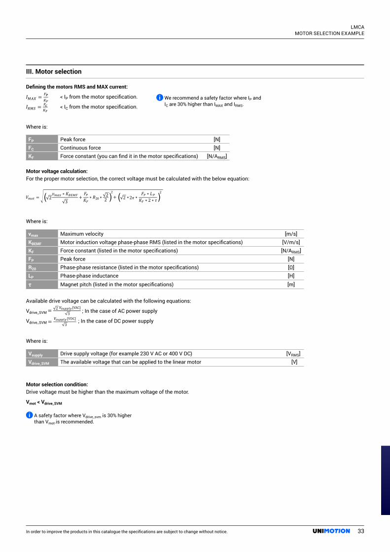
III. Motor selection
Defining the motors RMS and MAX current:
=
=
P
C
< IP from the motor specification.=
=
P
C < IC from the motor specification.
Where is:
FP Peak force [N]FC Continuous force [N]KF Force constant (you can find it in the motor specifications) [N/ARMS]
Motor voltage calculation:For the proper motor selection, the correct voltage must be calculated with the below equation:
Where is:
vmax Maximum velocity [m/s]KBEMF Motor induction voltage phase-phase RMS (listed in the motor specifications) [V/m/s]KF Force constant (listed in the motor specifications) [N/ARMS]FP Peak force [N]R20 Phase-phase resistance (listed in the motor specifications) [Ω]LP Phase-phase inductance [H]
τ Magnet pitch (listed in the motor specifications) [m]
Available drive voltage can be calculated with the following equations:
Vdrive_SVM ; In the case of AC power supply
Vdrive_SVM ; In the case of DC power supply
Where is:
Vsupply Drive supply voltage (for example 230 V AC or 400 V DC) [VRMS]Vdrive_SVM The available voltage that can be applied to the linear motor [V]
Motor selection condition:Drive voltage must be higher than the maximum voltage of the motor.
Vmot < Vdrive_SVM
( ) )(0 π
= 2 3
[VAC]
= 3
[VDC]
We recommend a safety factor where IP and IC are 30% higher than IMAX and IRMS.
A safety factor where Vdrive_svm is 30% higher than Vmot.is recommended.
33

In order to improve the products in this catalogue the specifications are subject to change without notice.
LMCA MOTOR SELECTION EXAMPLE
Selection example
I. Definition of the motion profile
– Moving distance L = 2 m – Moving time t = 2 s– Acceleration time ta = 0,5 s– Pause toff = 1 s– Mass of load mload = 50 kg– Friction coefficient kf = 0,01– α = 0°
Average velocity:
Maximum velocity:
Acceleration/deceleration:
II. Continuous and peak force calculation
Peak force:
Motor related parameters can be found in the motor specification:
– Attractive force FA = 958 N
t
ta ta toff
v [m/s]
t [s]
Velo
city
= = 22
= 1 m/s
= − =2
2 − 0,5 = 1,33 m/s
= =1,330,5 = 2,66 m/s
k
133,3 N
14,44 N
0 N
147,7 N
958
34

In order to improve the products in this catalogue the specifications are subject to change without notice.
LMCA MOTOR SELECTION EXAMPLE
Continuous force:
Motor related parameters, can be found in the motor specification:
– Attractive force FA = 958 N
III. Motor selection
Maximum motor current:
Continuous motor current:
Motor related parameters can be found in the motor specifications:
– Attractive force FA = 958 N– KF = 52,7 N/ARMS– IC = 3,0 ARMS– IP = 9,0 ARMS
Motor voltage calculation:
For a proper motor selection, voltage is also important, which must be applied by the servo drive. Maximum voltage is calculated by:
Motor related parameters can be found in the motor specification:
– Attractive force FA = 958 N– KF = 52,7 N/ARMS– KBEMF = 31,4 V/m/s– R20 = 4,99 Ω– LP = 28,2 mH– τ = 30 mm
Available drive voltage:
Vsupply = 230 VAC
Vdrive_SVM
P
77,85 N147,7 14,44 14,44
P
C
2,8 ARMS < 9,0 ARMS
1,48 ARMS < 3,0 ARMS
147,752,7
77,8552,7
P
C
2,8 ARMS < 9,0 ARMS
1,48 ARMS < 3,0 ARMS
147,752,7
77,8552,7
π 45,5 V( ) ( )
( ) )( π0
1,33 31,4* 147,752,7
4,99147,7 0,0282*52,7
187,8 V > 45,5 V
35

We cover all major markets. If you wish to
contact us, send us an enquiry and we will
be happy to assist you.
Unimotion: May 2021
NORTH AMERICA
Unimotion North America, Inc. 3952 Ben Hur Ave, Unit 5 Willoughby, OH 44094
T: +1 440-525-9106
GERMANY
Unimotion GmbHWaldstrasse 20D - 78736 Epfendorf
T +49 (0) 7404 930 85 60F +49 (0) 7404 930 85 61