light rail and emc - den danske banekonference | rail... · light rail and emc (management and ......
TRANSCRIPT
siemens.com© Siemens AG 2016 – All rights reserved.
Light Rail and EMC
Dr.-Ing. Lorenz Jung, Siemens AG, Mobility Division
Copenhagen, May 17th 2016

17/05/2016
© Siemens AG 2016 – All rights reserved.
Page 2 Mobility Division
Contents
Light Rail and EMC (Management and special Topics)
EMC: Definition and Coupling Model
Normative EMC Requirements
EMC Management
EMC Analysis / EMC Matrix
Special issues related to Light Rail
Systems / DC Systems
Magnetic Fields
Stray Currents

17/05/2016
© Siemens AG 2016 – All rights reserved.
Page 3 Mobility Division
Definition of Electro Magnetic Compatibility
Emissions
Must be limited, in order not to affect
radio communication services or
other apparatus.
limits for emission
EMC is the ability of an equipment or system to function satisfactorily in
its electromagnetic environment without introducing intolerable
electromagnetic disturbances to anything in that environment.
Immunity
„Immunity“ against electromagnetic
disturbances; needs to be present in
order apparatus not to be affected.
immunity levels

17/05/2016
© Siemens AG 2016 – All rights reserved.
Page 4 Mobility Division
EMC Coupling Model
Radiated Radiated
ConductedConducted
ImmunityEmission
Railway System
Subsystem (e.g. Signalling)
Installation (e.g. Interlocking)
Devices (e.g. Axle Counter)
Electromagnetic
Capacitive
Inductive
Electromagnetic
Capacitive
Inductive
Galvanic
GalvanicRadiated
Electromagnetic
Capacitive
Inductive

17/05/2016
© Siemens AG 2016 – All rights reserved.
Page 5 Mobility Division
EMC Railway Standards
EN 50121-x Series

17/05/2016
© Siemens AG 2016 – All rights reserved.
Page 6 Mobility Division
EMC Railway Standard - General
EN 50121-1
Management

17/05/2016
© Siemens AG 2016 – All rights reserved.
Page 7 Mobility Division
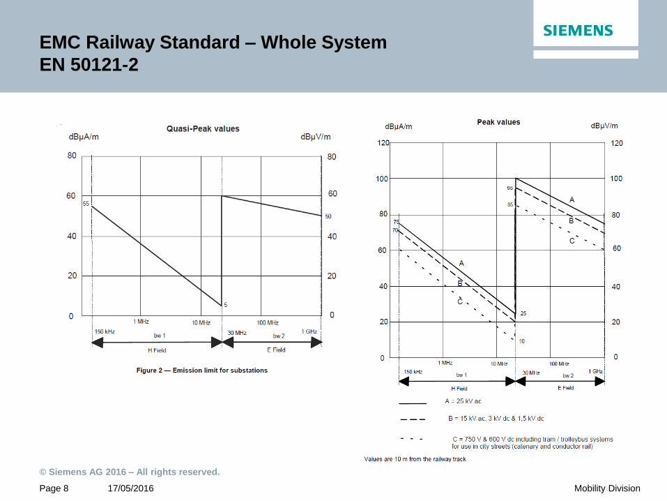
EMC Railway Standard – Whole System
EN 50121-2
Radiated
Fast movement, maximum power, electrical braking,
possibly other trains in operation
17/05/2016
© Siemens AG 2016 – All rights reserved.
Page 8 Mobility Division
EMC Railway Standard – Whole System
EN 50121-2

17/05/2016
© Siemens AG 2016 – All rights reserved.
Page 9 Mobility Division
EMC Railway Standard – Rolling Stock
EN 50121-3-1
Radiated
Standstill, slow moving, acceleration / braking,
only one train in operation

17/05/2016
© Siemens AG 2016 – All rights reserved.
Page 10 Mobility Division
EMC Railway Standard – Rolling Stock
EN 50121-3-1

17/05/2016
© Siemens AG 2016 – All rights reserved.
Page 11 Mobility Division
EMC Railway Standards - Apparatus
EN 50121-3-2, EN 50121-4 and EN 50121-5
Emission Testing in EMC Laboratory

17/05/2016
© Siemens AG 2016 – All rights reserved.
Page 12 Mobility Division
Selected EMC Immunity Levels of Apparatus in
Railway- and other Environments
Immunity Testing in EMC Laboratory
Environment Standard Frequency Range Level
Railway / Rolling Stock 50121-3-2 80 - 1000 MHz 20 V/m
Railway / Signalling 50121-4 800 - 1000 MHz 20 V/m
Railway / Signalling 50121-4 80 - 800 MHz 10 V/m
Railway / Substation 50121-5 800 - 1000 MHz 20 V/m
Railway / Substation 50121-5 80 - 800 MHz 10 V/m
Industrial 61000-6-2 80 - 1000 MHz 10 V/m
Residential 61000-6-1 80 - 1000 MHz 3 V/m
Residential Environment
Rolling Stock
Signalling and Substation
Industrial Environment

17/05/2016
© Siemens AG 2016 – All rights reserved.
Page 13 Mobility Division
Railway EMC Technical Specifications
(Low Frequency Phenomena, Train Detection)
Train harmonic Currents ( DC – 67 kHz) disturbing Track Circuits
Train local Magnetic Fields ( 27 kHz – 1.2 MHz) disturbing Axle Counters

17/05/2016
© Siemens AG 2016 – All rights reserved.
Page 14 Mobility Division
EMC Management
Why?
Stipulated by EN 50121-1
Emission and immunity standards do not cover the entire frequency range for
coupling between systems
Laboratory tests can only partially reproduce real world conditions
Many communication systems between rolling stock and wayside are not
covered by standards (loop systems, Eurobalise, train radio)
Environment of the railway system is not considered (only for protection of
radio services, what about broadcast stations, hospitals, etc. ?)
Proof of safe and reliable operation of the railway system

17/05/2016
© Siemens AG 2016 – All rights reserved.
Page 15 Mobility Division
EMC Management
How?
Orientated on the V-Model
On system and sub-system level
Data collection
Analysis
Solving of identified open issues
Design verification
Conformity report

17/05/2016
© Siemens AG 2016 – All rights reserved.
Page 16 Mobility Division
EMC Management
Site Survey
Identification of sources and sinks of Electro-
Magnetic Interference (EMI) in the environment
Sources: Radio transmitters, heavy industry,
adjacent railways
Sinks: Hospitals, universities or companies with
equipment sensitive to low frequency magnetic
fields (electron microscope, ecg, eeg)

17/05/2016
© Siemens AG 2016 – All rights reserved.
Page 17 Mobility Division
EMC Management
Matrix Analysis (1)
System A
System B
System C
Interaction

17/05/2016
© Siemens AG 2016 – All rights reserved.
Page 18 Mobility Division
EMC Management
Matrix Analysis (2)
Sinks
System A System B System C
So
urc
es
System A X1 ok nsp
System B ok X2 b
System C nsp H1 X3
Xn : see Submatrix n
- : n/a
nsp: No shared Ports
ok: due to EMC Data x and y
b: benign due to…..
…….
Hn: Hazard n

17/05/2016
© Siemens AG 2016 – All rights reserved.
Page 19 Mobility Division
EMC Management
Matrix Analysis (2)
Sinks
System A System B System C
So
urc
es
System A X1 ok nsp
System B ok X2 b
System C nsp H1 X3
Xn : see Submatrix n
- : n/a
nsp: No shared Ports
ok: due to EMC Data x and y
b: benign due to…..
…….
Hn: Hazard n
Comprehensive Matrix of Real-World-System will explode!

17/05/2016
© Siemens AG 2016 – All rights reserved.
Page 20 Mobility Division
EMC Management
Matrix Analysis (3)
interference sinks interference sources
signalling system
TCC TOB UPS outdoor components
points signal
s
TVD CBTC
(e.g.
APs)
extra (Name of Project) system
enclosure port signalling system
human beings
(ESD)
- - - - - - -
Implants,
cardiac
pacemaker
x x x nsp nsp nsp x
Medical
equipment
(hospital etc)
a a a d d d d
receiving
devices
(radio, TV,
mobile phones
etc)
a a a d d d d
computer &
laboratory
equipment
a a a d d d d
transmitting
devices
(radio, TV,
mobile phones
etc)
- - - - - - -
Lightning - - - - - - -
power port signalling system
public
electric
ity
system
- - u - - - -
Lightni
ng
- - - - - - -
interference sources interference sinks
signalling system
TCC TOB UPS outdoor components
poin
ts
signal
s
TVD CBT
C
extra (Name of Project) system
enclosure port signalling system
Human beings (ESD) e y y c c c c
implants, cardiac pacemaker - - - - - - -
medical equipment
(hospital etc)
- - - - - - -
receiving devices
(radio, TV, mobile phones etc)
- - - - - - -
computer & laboratory
equipment
- - - - - - -
transmitting devices
(radio, TV, mobile phones etc)
p p p p p p p
lightning b f b f f f f
power port signalling system
public electricity system nsp nsp u nsp nsp nsp nsp
lightning nsp nsp u nsp nsp nsp nsp

17/05/2016
© Siemens AG 2016 – All rights reserved.
Page 21 Mobility Division
EMC Management
Matrix Analysis (4)
Two Matrices each:
Extra-System Analysis: Overall System and Enviroment
(+ for Turnkey Projects: Each Subsystem and Environment)
Inter-System Analysis: Subsystems and other Subsystems
Intra-System Analysis: Components of individual Subsystem

17/05/2016
© Siemens AG 2016 – All rights reserved.
Page 22 Mobility Division
EMC Management
Matrix Analysis (4)
Two Matrices each:
Extra-System Analysis: Overall System and Enviroment
(For Turnkey Projects: Each Subsystem and Environment)
Inter-System Analysis: Subsystems and other Subsystems
Intra-System Analysis: Components of individual Subsystem
List of Hazards and open Issues

17/05/2016
© Siemens AG 2016 – All rights reserved.
Page 23 Mobility Division
EMC Management

17/05/2016
© Siemens AG 2016 – All rights reserved.
Page 24 Mobility Division
DC and Low Frequency Magnetic Fields
- High Traction Currents
For instance, there are magnetic flux density values to centre line of double track of
• 20 T in a distance of about r = 7 m
• 1 T in a distance of about r = 30 m
The calculation is based on 1000 A (500 A per catenary).
B ~ I/ r

17/05/2016
© Siemens AG 2016 – All rights reserved.
Page 25 Mobility Division
DC and Low Frequency Magnetic Fields
- Harmonic Currents of Light Rail Vehicle
Ivehicle @ DC max. > 1000 A Non-DC components less than 0.1% - 1% of max. DC-value
1
0.1
0.01
A
Hz
s

17/05/2016
© Siemens AG 2016 – All rights reserved.
Page 26 Mobility Division
DC and Low Frequency Magnetic Fields
- Immunity Values of Apparatus in Environment
For instance, there are DC magnetic flux density values to centre line of double track of
• 20 T in a distance of about r = 7 m
• 1 T in a distance of about r = 30 m
The calculation is based on 1000 A DC
Example for LR-vehicle: IDC max. 1000 A with non-DC components less than 0.1% - 1% of max. DC-value
Various Immunity Levels DC 50 Hz
Cardiac Pacemaker 500 µT 76 µT
Apparatus in Railway Environment 375 µT 125 µT
Apparatus in Industrial Environment 37.5 µT
Apparatus in Residential Environment 3.75 µT
Cathode Ray Tube Monitor 20 µT 1 µT
Electrocardiogram ( ECG) 0.16 µT *)
Electroencephalogram (EEG) 0.08 µT *)
Electromyogram (EMG) 0.04 µT *)
*) Value for Information only from DIN VDE 0100-710 (2012)

17/05/2016
© Siemens AG 2016 – All rights reserved.
Page 27 Mobility Division
DC and Low Frequency Magnetic Fields
- Mitigation by Shielding is not a realistic Option
0 < Hinside < Houtside
Houtside Houtside
‚Faraday Cage‘ (for electric shielding)
works because of nearly perfect electrical
conductivity of materials.
Magnetic shielding depends on the
magnetic conductivity (permeability) of
materials, which is usually poor.
Material Relative Permeability µr
Air 1
Copper, Aluminium 1
Stainless Steel 1
Steel 100
Iron 200
Transformer Plate 750
Mu-metal50,000 - 140,000
150 if mechanically stressed

17/05/2016
© Siemens AG 2016 – All rights reserved.
Page 28 Mobility Division
DC Stray Currents
- Electrical Corrosion
Electrolytic erosion M of metal per Ampere and per year according to
Faraday’s law of electrochemical equivalent with
M = Metal constants * Current * Time:
MSteel = 9.13 kg/A*Year or a volume 1.16 dm3 for buried structure
Rail insulation Corrosion area

17/05/2016
© Siemens AG 2016 – All rights reserved.
Page 29 Mobility Division
DC Stray Currents
- Electrical Corrosion

17/05/2016
© Siemens AG 2016 – All rights reserved.
Page 30 Mobility Division
DC Stray Currents
- Mitigation: Rail Insulation
Open Formation Closed Formation

17/05/2016
© Siemens AG 2016 – All rights reserved.
Page 31 Mobility Division
DC Stray Currents
- Mitigation?: Rail Insulation

17/05/2016
© Siemens AG 2016 – All rights reserved.
Page 32 Mobility Division
DC Stray Currents
- Mitigation: Structure E&B System
Experience: The total minimum cross section of longitudinal earthing bars
should be 800 mm² for double track

17/05/2016
© Siemens AG 2016 – All rights reserved.
Page 33 Mobility Division
…
Thank you for your
Attention!
Questions?