lift-out rail systems - hydromaticlift-out rail systems 293 wright st., delavan, wi 53115 ......
TRANSCRIPT
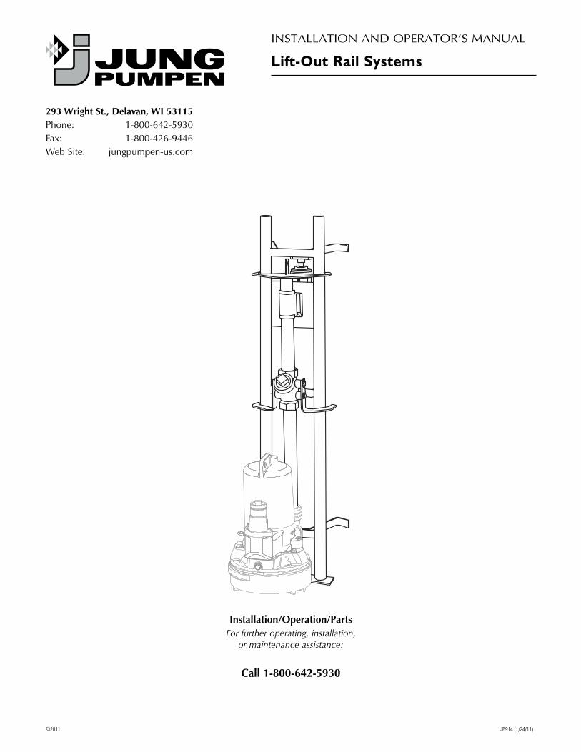
Installation/Operation/PartsFor further operating, installation,
or maintenance assistance:
Call 1-800-642-5930
©2011 JP914 (1/24/11)
InstallatIon and operator’s Manual
Lift-Out Rail Systems
293 Wright St., Delavan, WI 53115phone: 1-800-642-5930Fax: 1-800-426-9446Web site: jungpumpen-us.com
Safety 2
For parts or assistance, call Jung Pumpen Customer Service at 1-800-642-5930
Important Safety InstructionsSAVE THESE INSTRUCTIONS - this manual contains important instructions that should be followed during installation, operation, and maintenance of the product. save this manual for future reference.
this is the safety alert symbol. When you see this symbol on your pump or in this manual, look for one of the following signal words and be alert to the potential for personal injury!
indicates a hazard which, if not avoided, will result in death or serious injury.
indicates a hazard which, if not avoided, could result in death or serious injury.
indicates a hazard which, if not avoided, could result in minor or moderate injury.NOTICE addresses practices not related to personal injury.
Risk of explosion and hazardous gas. Improper ventilation of sewer gases can result in leakage of methane sewer gas, and a possible explosion of fumes, resulting in severe injury or death.• Ventbasinaccordingtoalllocalcodes.Proper
ventilation is needed to prevent negative basin pressure and to provide air for proper aerobic activity within the basin.
• Checkyourlocalcodesbeforeinstalling.Youmustcomply with their rules.
• Donotinstallbasinandpumpinanylocationclassified as hazardous by the united states national ElectricalCode(NEC),orbytheCanadianElectricalCode(CEC),whereapplicable.
• Donotsmokeorusesparkableelectricaldevicesorflameinaseptic(gaseous)orpossiblysepticsump.
• Thepumpsusedwiththissystemaredesignedto handle materials which could cause illness or disease through direct exposure. Wear adequate protective clothing when working on the pump or piping.
• Ifasepticsumpconditionexistsandifentryintosumpisnecessary,then(1)providepropersafetyprecautionsperOSHArequirementsand(2)donot enter sump until these precautions are strictly adhered to.
• Sumpcoversareusedtoexcluderefusefromthesumpbasin.Consultlocalcodeforsumpcoverspecifications.
Hazardous voltage.Canshock,burn,starta fire, or kill. When installing, operating, or servicing a sewage pump, follow electrical safety instructions. only trained service personnel should install or service this pump.• Disconnectthepumpfromthepowersourcebefore
handling or servicing.• Anywiringtobedoneonpumpsshouldbedoneby
a qualified electrician.• Neveroperateapumpwithapowercordthathas
frayed or brittle insulation.• Neverletcordsorplugslayinwater.• Neverhandleconnectedpowercordswith
wet hands.• Donotliftpumpbythepowercord.• Donotoperatepumpwithoutallsafetydevices
in place.
ContentsImportant Safety Instructions . . . . . . . . . . . . . . . . . . . . . . .2Installation . . . . . . . . . . . . . . . . . . . . . . . . . . . . . . . . . . . . . . .3
Mo unting Cover and Assembled Rail Sections . . . . . . . . . . 3
Mo unting Cover and Component Rail Pieces . . . . . . . . . . . 4
Attach Pump to Movable Section . . . . . . . . . . . . . . . . . . . . 5
Operation . . . . . . . . . . . . . . . . . . . . . . . . . . . . . . . . . . . . . . . .6Maintenance . . . . . . . . . . . . . . . . . . . . . . . . . . . . . . . . . . . . . .6Troubleshooting . . . . . . . . . . . . . . . . . . . . . . . . . . . . . . . . . .7Product Specifications . . . . . . . . . . . . . . . . . . . . . . . . . . . . .7Repair Parts . . . . . . . . . . . . . . . . . . . . . . . . . . . . . . . . . . . . . .8Warranty . . . . . . . . . . . . . . . . . . . . . . . . . . . . . . . . . . . . . . .12

Safety • Installation 3
For parts or assistance, call Jung Pumpen Customer Service at 1-800-642-5930
Descriptionthank you for purchasing this Jung pumpen product. to help ensure years of trouble-free operation, please read this manual carefully. Jung pumpen corrosion resistant rail lift systems are used in residential, commercial, and industrial sewage, effluent drainage and seepage water pumping systems. the basic system includes all required rails, quick disconnect fittings, supports, and hardware. additional rail segments and intermediate bracing are available to lengthen the rail system.These installation instructions are not intended to preclude normal safety procedures, which should be followed to prevent injury to personnel. Safe installation procedures shall be entirely the responsibility of the installer.In addition to proper system engineering and competent manufacturing, the use of rail system installers who have both practical experience and integrity to insist that the equipment be installed properly constitutes the greatest protection from component failure and liability exposure.stainless steel rail lift systems normally give many years of trouble-free service when correctly installed, maintained, and used. However, unusual circumstances (freezing,blockage,etc)maypreventyoursystemfromfunctioning normally. to prevent possible damage, consult your dealer about installing alarm or other warning devices.see Troubleshooting in this manual for information about common rail system problems and remedies. For more information, see your retailer, call Jung pumpen customer service at 1-800-642-5930, or visit our web site at jungpumpen-us.com.
InstallationGeneral Informationthese instructions apply to lift systems designed for pumps with 1-1/4” npt or 2” npt discharge and 4” horizontal discharge flanged pumps, up to 7-1/2 Hp and up to 300 lb. in weight.Flow Components: the movable disconnect is made of brass or cast iron. the ball check valve is made of cast ironorPVC.ThegatevalveismadeofbrassorPVC.Rail Components: the rails, brackets, guide plates and arms, couplers, and hardware are made of stainless steel.Lift-Out Chain / Cable: the chain/cable package is stainless steel. each package is designed to attach to the top of the pump and also to the guide plate which is part of the movable disconnect. each package is designed to allow the pump to be safely hoisted up the guide rail.
Basin Cover: several types of basin covers are available for use with either fiberglass or concrete basins. Basin hatch type covers are available in either steel or aluminum construction.Basin Bottom: all cement pipe basins must have a smooth level troweled bottom for level mounting of the base plate.
Mo unting Cover and Assembled Rail Sections
safe installation procedures are the sole responsibility of the lift system installer. Work safety requirements are definedinUSDepartmentofLabor29 CFRpart 1926.1. set concrete cover with hatch opening in position
over basin.2. lower the assembled rail system into the basin and
attach wall bracket to rail system using supplied fasteners. Fasten the wall bracket to the side of the basin. a typical assembly is shown in Figure 1.
Figure 1: SGR125 and SGR200 Typical Assembly
48”
36”
48”
2.5”
11”
1
3
2

Installation 4
For parts or assistance, call Jung Pumpen Customer Service at 1-800-642-5930
3. position the base side-to-side and front-to-back so that the rail assembly is plumb. level the base plate - shims may be required under the base in order to obtain a level condition. Mark the position of the base hold down bolts through the holes in the base.
4. Move the base aside to allow drilling for 3/8” expansion bolts, 2” long. Move the base over the bolt holes and recheck for level and plumb. Install expansion bolts.
5. place tube coupler in position in each rail pipe. position another assembled rail section over the couplers and secure the wall bracket to the rail section and the side of the basin. attach the attachment brace to the lower rail section.
6. Continueaddingrailsectionsperstep5untilthedesired rail height is achieved. If a section less than 48” is needed, either cut that length off the bottom of the rail section or procure a 12” or 24” preassembled section.
7. once all rail sections have been installed and the rails aligned, install discharge pipe as required by the particular job specifications. tighten all fasteners.
NOTICE: discharge pipe and guide rails must be plumb and parallel regardless of the number of rail sections used.
Mo unting Cover and Component Rail Pieces
1. set concrete cover with hatch opening in position over basin.
2. Fasten the upper guide rail bracket to the side of the basin cover opening using appropriate fasteners.
3. place the base elbow on the floor of the basin and position it side-to-side and front-to-back so that the rails will be plumb and aligned with the upper bracket. level the base - shims may be required under the base in order to obtain a level condition. Mark the position of the base hold down bolts through the holes in the base. Figure 2 and 3 show the typical arrangement of system components.
4. Move the base aside to allow drilling for 3/8” expansion bolts, 3” long. Move the base over the bolt holes and recheck for level and plumb. Install expansion bolts.
5. place guide tubes in position between the upper guide rail bracket and each base elbow rail post. Mark tubes for correct length and trim to fit. If total rail length is more than 15 feet, procure and attach an intermediate bracket to the basin wall at the midpoint of the rails.
6. plumb and square the entire rail system. tighten all fasteners appropriately.
7. Install discharge pipe, check valve and gate valve, as required by the particular job specifications.
Figure 2: 1-1/4” and 2” System Components
7.125”4”
7”
17”
12.75”
Figure 3: 4” System Components
8.125”12”
10”
15.75”

Installation 5
For parts or assistance, call Jung Pumpen Customer Service at 1-800-642-5930
Attach Pump to Movable Section1. For 1-1/4” discharge pipe using preassembled rail
sections, thread the supplied stainless steel pipe into pump elbow and then reassemble the guide arm/disconnect/check valve assembly to the pipe. tighten assembly until pump is perpendicular to the guide arm/disconnect.
2. For 1-1/4” discharge pipe using the cast iron base elbow, thread pump adapter flange into pump elbow fitting.Connectadapterflangetopull-outdisconnectusing supplied yoke and bolts, making sure o-ring is correctly positioned.
3. For 4” discharge pipe, bolt pump flange to cast iron quick disconnect using poK-0400 hardware set. Make sure the rubber gasket is correctly positioned on the pump flange before tightening fasteners.
Attach Lift Chain/Cable1. attach lifting chain bail with one end on the lifting
eye on pump and the other end on the guide plate attachment point.
2. attach the lifting chain or cable to the bail with a clevis, sliding the clevis along bail until the center of gravity is found.
3. a hook is located on the upper rail support to hold the upper end of the chain/cable when not in use. repeat steps 1 and 2 for second pump, if duplex operation is required.
4. position pump so the upper stand-off bracket captivates both lift rails. If equipped, the lower stand-off bracket must rest against both rails. slowly lower the pump down the guide rails with the lift chain/cable until the quick disconnect components fully engage.
5. retain the power cord at the surface as pump is lowered on the rails. do not lift or lower pump using power cord. When pump is fully lowered, connect power cord to control box, leaving a slight amount of slack.
Attach and Adjust Float Level Controlsthe float level controls maintain the basin sewage level by controlling pump turn-on and turn-off conditions. attach level sensing float switches to bracket. General rules to set level sensing heights are as follows:1. the lower turn-off switch should be set so that the
pump stops when the fluid is approximately level withthetopofthepump.Consultthepumpmanualfor any settings below this point.
2. the upper turn-on switch should be set above the lower turn-off switch. the exact height between the two controls is determined by the number of pump starts desired and depth of the basin. a maximum of 10 starts per hour should not be exceeded.
3. If equipped, the override switch is set at a specified height above the upper turn-on control.
4. the alarm switch is set about 6” to 12” above the override control.
5. no switch should be set above the inlet pipe.
Operation • Maintenance 6
For parts or assistance, call Jung Pumpen Customer Service at 1-800-642-5930
Operation Risk of explosion and hazardous gas. after
the pump is installed and sewage has entered the basin, poisonous methane and hydrogen sulfide gases are present. never enter a wet well unless the cover is open for a sufficient period of time to allow fresh air into the basin. It is recommended that a man in the basin wear a harness attached to a rope to the surface, so that he can be pulled out in case of asphyxiation. the rail lift-out system is designed so that no service is required inside the basin.to avoid overheating the pump motor for continuous operation, the pump must be completely submerged in liquid. set the level switches to maintain this submerged condition. do not allow the pump to run in a dry sump. It will void the warranty and may damage the pump.the pump builds up heat and pressure during operation - allow time for pump to cool before handling or servicing. only qualified personnel should install, operate or repair lift system or pump. Keep clear of suction and discharge openings. do not insert fingers in pump with power connected.Thesumpbasinandlid(orhatch),pump,andpipingshould be protected from freezing temperatures. If there is any danger of freezing temperatures, the basin should bedrained.Consultyourpumpmanualforinstructionson how to drain the pump to protect it from freezing.
Maintenanceonly qualified mechanics with proper tools and knowledge should attempt to service this pump.
Heavy parts. use lifting gear of appropriate capacitypositioneddirectlyoverliftpoint(s).
Risk of infection from pathogens(suchashepatitis)whichcancollectonpumpduringnormaloperation. submerge the complete pump in a disinfectant solution(dilutechlorinebleach)foratleastonehourbefore disassembly.the pump must always be lifted by the lift-out chain or cable and never by the power supply cable.other than local authority mandated inspections, there is no routine maintenance required for the basin system. refer to the pump manual for any pump-related maintenance procedures.

Troubleshooting • Product Specifications 7
For parts or assistance, call Jung Pumpen Customer Service at 1-800-642-5930
Symptom Possible Cause(s) Corrective Action
pump will run but not deliver water probable air lock start and stop pump several times using manual switch. If this does not clear air, turn pump to oFF and run 6 to 12 inches more water into basin. If air still does not clear, it may be necessary to raise hold-down pipe and lift pump so that lower seal fitting is out of the discharge case to release air.
shut-off or gate valve closed Be sure shut off valve is open in discharge line
pump seal fitting leaks probable cut or broken o-ring replace if necessary
trash caught in seal flange lift pump and clear trash from flange
Moveable section misaligned with fixed section lift pump and correct alignment problem.
pump does not run. other problem with pump or control box refer to pump and control box operating instructions for assistance
Product SpecificationsModel Guide Rails - Hardware Pump Inlet Disconnect/Base Discharge Pipe Size
SGR 125stainless steel
1-1/4” nptBrass
1-1/4” npt
SGR 200 2” npt
2” npt1-1/4” Base Elbow System
InstallerChoice
1-1/4” npt
CastIron2” Base Elbow System 2” npt
4” Flange Elbow System 4”Flange,ANSIClass125 4”Flange,ANSIClass125
Troubleshooting

For parts or assistance, call Jung Pumpen Customer Service at 1-800-642-5930
Repair Parts 8
SGR125 and SGR200 Systems
10
11
13
16
21
14
17
9
99
9
3,4
88
8
18,19
22,23
12
17

For parts or assistance, call Jung Pumpen Customer Service at 1-800-642-5930
Repair Parts 9
SGR125 and SGR200 Systems
Item No. Description SGR125 SGR200
3 Brass Quick disconnect BF20Xn sF70Xn
4 disconnect o-ring BF20Xn-or27t sF70Xn-or28t
8 PVCGuiderailTubeCoupler sGr-0100 sGr-0100
9 SSGuideRailWallBracket(Includesalladjustmentandattachmenthardware) sGr-101 sGr-101
10 SSGuideRailExtensionKit-12”(Includesallpartsshownwithinframe) sGr125-12/eXt sGr200-12/eXt
11 SSGuideRailExtensionKit-24”(Includesallpartsshownwithinframe) sGr125-24/eXt sGr200-24/eXt
12 SSGuideRailPackage(2)48”Sections(Includesallpartsshownwithinframes) sGr125-48/48 sGr200-48/48
13 SSGuideRailExtensionKit-48”(Includesallpartsshownwithinframe) sGr125-48/eXt sGr200-48/eXt
14 SSLowerStandoffBracket(Includesallattachmenthardware) sGr125lpB1a sGr200lpB1a
15 MovableSideofRailAssembly(includesitems3,4,14,fastenersfor14,16,17,21,22/23)) sGr125Ms sGr200Ms
16 ss upper Guide rail Bracket sGr125uGBa sGr200uGBa
17 SSVerticalPipeNipple SGR125VN SGR200VN
18 SSValveExtensionHandle-48” SSVH125-04 SSVH200-04
19 SSValveExtensionHandle-72” SSVH125-06 SSVH200-06
21 CastIronBallCheckValve 16-0600 16-0601
22 SSLiftingCable3/16”X48”w/Hardware SSLC-04 SSLC-04
23 SSLiftingCable3/16”X96”w/Hardware SSLC-08 SSLC-08
* BrassThreadedGateValve 16-0300 16-0302
each part number listed above is available separately* not shown

For parts or assistance, call Jung Pumpen Customer Service at 1-800-642-5930
Repair Parts 10
1-1/4” and 2” Base Elbow System
5 20
1
6
2
Item No. Description 1-1/4” Components 2” Components
1 Base elbow, pull out Flange type Bers-0125 Bers-0200
2 replacement o-ring Kit Bers-or0200 Bers-or0200
5 ss lower Guide rail plate lGrp-ss lGrp-ss
6 PullOutFlange(Includesallitemsshowninframe) poF-0125 poF-0200
20 ss upper Guide rail Bracket uGB-stnls uGB-stnls
* SSLiftingCable3/16”X48”w/Hardware SSLC-04 SSLC-04
* SSLiftingCable3/16”X96”w/Hardware SSLC-08 SSLC-08
each component available separately* not shown

For parts or assistance, call Jung Pumpen Customer Service at 1-800-642-5930
Repair Parts 11
4” Flanged Base Elbow System
7
2
20
1
Item No. Description 4” Components
1 Base elbow, pull out Flange type Bers-0400
2 replacement sst sealing ring Bers-rnG0400s
7 Hardware pack poK-0400
20 ss upper Guide rail Bracket uGB-0200
CastIronFlangedGateValve 16-0352
CastironSwingCheckValve 16-0152
SSChain3/16”X10’w/2Shackles CHNSS10
SSChain3/16”X15’w/2Shackles CHNSS15
each component available separately* not shown

Warranty 12
For parts or assistance, call Jung Pumpen Customer Service at 1-800-642-5930
Limited WarrantyJung Pumpen warrants to the original consumer purchaser (“Purchaser” or “You”) of Jung Pumpen Effluent Pumps, Sewage Pumps, and Package Systems, that they will be free from defects in material and workmanship for the Warranty Period of 12 months from date of manufacture.Our warranty will not apply to any product that, in our sole judgement, has been subject to negligence, misapplication, improper installation, or improper maintenance. Without limiting the foregoing, operating a three phase motor with single phase power through a phase converter will void the warranty. Note also that three phase motors must be protected by three-leg, ambient compensated, extra-quick trip overload relays of the recommended size or the warranty is void.Your only remedy, and Jung Pumpen’s only duty, is that Jung Pumpen repair or replace defective products (at Jung Pumpen’s choice). You must pay all labor and shipping charges associated with this warranty and must request warranty service through the installing dealer or selling distributor as soon as a problem is discovered. No request for service will be accepted if received after the Warranty Period has expired. This warranty is not transferable.EXCEPTIONS: Special Application Pumps, Filtered Effluent Pumps, Grinder Pumps, 2-1/2” Sewage Pumps, and Lift Systems are warranted for a period of 12 months from date of purchase or 18 months from date of manufacture, whichever comes first.Jung Pumpen SHALL NOT BE LIABLE FOR ANY CONSEQUENTIAL, INCIDENTAL, OR CONTINGENT DAMAGES WHATSOEVER.THE FOREGOING LIMITED WARRANTIES ARE EXCLUSIVE AND IN LIEU OF ALL OTHER EXPRESS AND IMPLIED WARRANTIES, INCLUDING BUT NOT LIMITED TO THE IMPLIED WARRANTIES OF MERCHANTABILITY AND FITNESS FOR A PARTICULAR PURPOSE. THE FOREGOING WARRANTIES SHALL NOT EXTEND BEYOND THE DURATION EXPRESSLY PROVIDED HEREIN.Some states do not allow the exclusion or limitation of incidental or consequential damages or limitations on the duration of an implied warranty, so the above limitations or exclusions may not apply to You. This warranty gives You specific legal rights and You may also have other rights which vary from state to state.This limited warranty supersedes and replaces all previous warranty publications.
Jung Pumpen 293 Wright Street, Delavan, WI 53115
Phone: 800-642-5930 • jungpumpen-us.com