owner’s manual model b4jrmbh(s) frame mounted … · 293 wright street, delavan, wi 53115 ph:...
TRANSCRIPT
293 WRIGHT STREET, DELAVAN, WI 53115 WWW.BERKELEYPUMPS.COMPH: 888-237-5353
owner’s Manual Model B4JRMBH(S)
Frame Mounted Centrifugal Pump Hydraulic Coupling Drive
© 2013 Pentair, Ltd. All Rights Reserved. BE1015-BERKELEY (Rev. 03/21/13)
ImportantFor best possible performance and continuous, satisfactory operation, read these instructions before installing your new pump.Should service be required, this manual can be a valuable guide. It should be kept near the installation for ready reference.
Table of Contents
Page 2
• Safety ...................................................................................................................................... 3
• Transport and Storage ..................................................................................................... 4
• Pump Nomenclature General Information ........................................................................................................... 5 Parts Breakdown .......................................................................................................... 6, 7
• Start-up General Information ....................................................................................................... 8, 9
• Maintenance Routine Inspection ........................................................................................................... 10 General Information ......................................................................................................... 11 Packing Ring Replacement ............................................................................................ 12 Shaft Sleeve Installation/Replacement ........................................................................... 13 Impeller Replacement ..................................................................................................... 14 Mechanical Seal Maintenance/Replacement .................................................................. 15 Shaft Maintenance/Replacement .................................................................................... 16
• Troubleshooting ............................................................................................................... 17
• Warranty .............................................................................................................................. 18
Page

General InformationSafety First
Page 3
General SafetyDo not allow pump, piping, or any other system component containing water to freeze. Freezing may damage system, leading to injury or flooding. Allowing pump or system components to freeze will void warranty.
Pump approved liquids only with this pump.
Periodically inspect pump and system components.
Wear safety glasses at all times when working on pumps.
Keep work area clean, uncluttered and properly lighted; store properly all unused tools and equipment.
Keep visitors at a safe distance from the work areas.
California Proposition 65 Warning
This product and related accessories contain chemicals known to the State of California to cause cancer, birth defects or other reproductive harm.
Rotating parts. Can catch hands, feet, or clothing.Stay clear of equipment and keep shields in place while pump is running. Stop motor or engine before servicing pump.Read owner’s manual before using equipment.
WARNING
READ AND FOLLOW SAFETY INSTRUCTIONS!
This is the safety alert symbol. When you see this symbol on your pump or in this manual, look
for one of the following signal words and be alert to the potential for personal injury:
warns about hazards that will cause
serious personal injury, death or major property damage if ignored.
warns about hazards that will or can
cause serious personal injury, death or major property damage if ignored.
warns about hazards that will or can cause
minor personal injury or property damage if ignored.The label NOTICE indicates special instructions which are important but not related to hazards.Carefully read and follow all safety instructions in this manual and on pump.Keep safety labels in good condition. Replace missing or damaged safety labels.
INSTALLATION
Heavy weights; risk of crushing toes or feet. Use care and proper lifting equipment when handling pump for installation. Size and weight of some units will require hoists for safe handling.
When properly positioned, the suction and discharge openings of the pump will be aligned with system piping.

Page 4 F00637
General InformationTransport and Storage
TRANSPORT AND STORAGETRANSPORT AND HANDLING REqUIREMENTS The pump has been prepared for shipment at the factory in such a way as to minimize potential damage due to handling and transport.
RIGGING AND LIFTING The following instructions are for the safe handling of the pump. When shipment is received extreme care should be exercised during unloading. Heavy parts should be skidded to the ground if lifting equipment is not available. It is recommended a forklift be used to unload equipment.Bare pump: Using a nylon sling, chain, or wire rope, hitch around both the inboard and outboard bearing housings. Size the equipment for the load, and so the lift angle will be less than 45° from the vertical.
RECEIPT, INSPECTION, AND DAMAGE REPORTING Immediately upon receipt of the pump equipment, carefully check to see that all items have been received and are in undamaged condition. Report any shortage or damage to the transport company handling the shipment and to the equipment manufacturer, noting the extent of damage or shortage on the freight bill and bill of lading. This should be done at once. Do not unpack any more than required to verify that the equipment is complete and undamaged unless installation is to be done immediately. Do not leave the pump unit or any accessories exposed to weather or construction hazards, which may cause damage to the equipment.
SHORT-TERM STORAGE The pump and equipment, as shipped, have adequate protection for short-term (up to three months) storage in a covered, dry, and ventilated location prior to installation.
LONG-TERM STORAGE If the equipment will be subject to extended (more than three months) storage prior to installation and commissioning, then the standard warranty of the equipment may be affected. Periodic rotation of the pump and driver shaft is recommended during long-term storage (consult the equipment manufacturer as to the frequency), and inspection of the equipment by a factory representative prior to start-up is normally required to ensure equipment integrity and compliance with warranty requirements.
• Remove and discard stuffing-box packing. Fill the stuffing box with a crusting grease (Rust-Ban 326 or equal), then pack the end of the stuffing box with rolled vapor phase inhibitor paper and seal with weatherproof tape.
• Dry pump internals and spray the liquid end with a water-displacement rust inhibitor (Rust-Ban 392, Crown 6011, Arma 245, Ensis fluid 254, Sunkote 1303, or equal).
• Enclose vapor inhibitor in pump internals (Shell VPI 260 or equal).
• Apply a film of compatible lube oil over the water-displacement rust preventative. A compatible lube oil is Rust-Ban 632 or equivalent.
• After the pump has been thoroughly drained, cover the pump suction and discharge flanges with full gasket material and blank off these openings with metal blank flanges and a minimum of four full-sized bolts. Cover the pump stuffing-box opening with a nonhygroscopic tape. If packed-type pump, the packing gland may be left on the pump shaft, but should be wired or otherwise securely fastened in position. If mechanical seals have been used, then the annular opening between seal plate and shaft should be closed by a nonhygroscopic tape to exclude airborne dust.
• All exposed machined surfaces should be thoroughly coated with a firm film rust-preventative material (Rust-Ban 373, CRC-SP-350, Enis fluid 264, Protec 612801, or equal) that is readily removable with a petroleum distillate product.
• All exposed painted surfaces should be dry, clean, and free of grease and other contaminates.
• The pump should be covered with a weather-resistant cover of waterproof paper or plastic to prohibit the buildup of dirt and dust accumulations.
• The pump should be inspected at regular periods during storage, and the pump shaft should be rotated by hand at intervals of approximately four to six weeks.
• To place the pump in operation, all protective coverings and coatings should be properly removed. If packed type pump, then repack with the proper number of packing rings in each stuffing box in accordance with normal repair and maintenance instructions furnished with the pump.
• Rotate pump shaft several revolutions at least once per week to coat the bearing with lubricant and to retard oxidation and corrosion, flat spots, and staining.
• Long-term storage procedures should be followed as detailed by the OEM when the start-up of equipment is made over three months from the date of shipment from the factory.

F00637 Page 5
General InformationPump Nomenclature
ORDERING REPLACEMENT PARTSLocate the nameplate on the pump, plate is normally on the bearing bracket. Information found on this plate is shown below. To ensure correct parts are received, provide all nameplate data when ordering. The B.M. (Bill of Material) number is the most important. Write your nameplate information on the blank nameplate below for future reference as nameplates can become worn or lost.
Illustration on the following page show typical com-ponents used in the assembly of bearing frame mounted centrifugal pumps. Refer to this drawing when ordering any replacement parts.
SAMPLE ONLY
MODEL S.N. OR DATE
IMPELLER DIA. B.M.
6610 0712
B86084
B4JRMBHS
13-1/2"
MODEL S.N. OR DATE
IMPELLER DIA. B.M.
344 1093
Record your nameplate data here.

Page 6
Pump Nomenclature
Parts Breakdown
• Drawing is representative of a typical bearing frame pump. Parts on some models may vary slightly.
Bearing Frame Mount/Packing Seal
O-Ring
Impeller Washer
Hex Capscrew
Lock External Tooth Washer
Casing
Wear RingCasing
O-Ring
Impeller
Wear Ring
Seal Plate
Frame Mount Bracket
GreaseFitting
Hex Capscrew
Pipe Plug
Stud
Hex NutShaft Sleeve
Bearing Cap Motor Bracket
Oil Seal
Ball Bearing
Roller Bearing
Water Slinger
Thrust Ring
Grease Fitting
External Retaining Ring
Shaft
Slotted Split Gland
Packing Rings
Metallic Ring
6579-0712
Oil Seal
Hex Capscrew
FIGURE 1
Page 7
Parts Breakdown
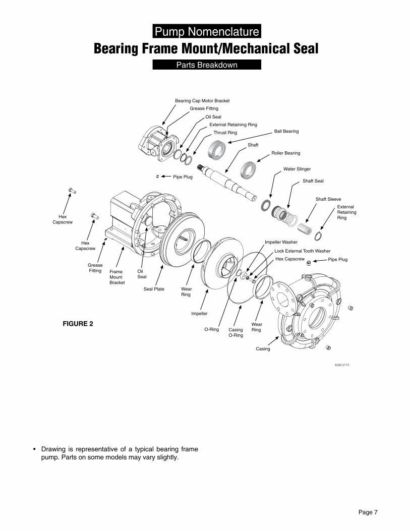
Bearing Frame Mount/Mechanical SealPump Nomenclature
• Drawing is representative of a typical bearing frame pump. Parts on some models may vary slightly.
6580 0712
Casing
Wear RingCasing
O-Ring
Impeller
Wear Ring
Seal Plate
Frame Mount Bracket
GreaseFitting
Hex Capscrew
Pipe Plug
Oil Seal
Hex Capscrew
Shaft Sleeve
Pipe Plug
Roller Bearing
Shaft
Bearing Cap Motor Bracket
Oil Seal
Thrust Ring
Grease Fitting
O-Ring
Ball Bearing
External Retaining Ring
Water Slinger
Shaft Seal
External Retaining Ring
Impeller Washer
Hex Capscrew
Lock External Tooth Washer
FIGURE 2

Page 8
General InformationStart-up
Clo
ckw
ise
rotation
12
6
39
6588 0712
PIPINGSystem piping should be at least one commercial pipe size larger than pump connections and flow velocity should not exceed eight (8) feet per second. Suction and discharge pipes must be naturally aligned with pump connections.
NOTICE Misalignment of piping with pump case or excessive pipe strain can cause distortion of pump components resulting in rubbing, breakage and reduced pump life.
Insure that piping is supported in a manner that prevents the exertion of force on pump connections. This can be checked by the following procedure. With the pump shut down, remove pipe flange bolts. If the mating flanges come apart or shift, misalignment is present and causing pressure on the connections. Adjust pipe supports until flanges mate without any force. This procedure can be done throughout piping system.
LUBRICATIONLIQUID END of pump requires no lubrication. Wear rings, packing rings, and models using a mechanicalshaft seal are lubricated by the liquid being pumped. Do not run dry!
BEARING FRAME
General maintenance - add approximately 5.5 ounces (150cc) of a lithium-based NGLI No. 2 extra pressure ball bearing grease to the outboard bearing and 2.5 ounces (75 cc) to the inboard bearing every 90 days.
NOTICE Excess grease will cause bearings to run hot.
The following are factory approved brands of grease for use with Berkeley Pumps: Alvania EP2, Shell Oil;Mobilith AW2, Mobil Oil, Ronex MP, Exxon, Litholine EP2, Atlantic Richfield; and Amolith EP2, Amoco.
PRIMINGPump priming is the displacement of air with water in the pump and suction piping. Pump MUST BE completely filled with water when operating.
HYDRAULIC BALANCED PUMPS
Hydraulic balanced pumps operate with a very low positive pressure across the stuffing box, permitting a much looser fit of the packing rings around the shaft sleeve to control the loss of water from the pump through the stuffing box.
PUMP PRIMING INSTALLATION WITH FLOODED SUCTION
• Open air vent (or pipe plug) in the highest tapped opening in pump case.
• Open inlet isolation valve, allowing water to fill the pump completely and force all air out through vent.
• Rotate shaft slowly allowing any air trapped in impeller to escape.
• Close vent opening when water without air emerges.
CHECk ROTATIONBefore pump is put into operation, rotational direction must be checked to assure proper performance of pump. Refer to FIGURE 3.
STARTINGNOTICE Never run pump dry. Running pump without water will overheat pump and damage internal parts. Always make sure pump is primed prior to start-up.
NOTICE Refer to maintenance section if pump has packing for adjustment prior to start-up.
Set discharge valve to minimum flow. Turn on power to pump. Slowly open discharge valve until desired flow rate is achieved.
PACkING Starting new pump. Before starting pump for the first time, loosen gland nuts and retighten finger tight. Proceed with pump start-up procedure. Allow packing to leak liberally for a few moments. Then tighten gland nuts one complete turn each until leakage is reduced to 40 to 60 drops per minute.
STOPPINGPump will stop automatically when the flow to the driver motor stops. If hydraulic shock occurs, the check valve closure rate may need adjustment or additional controls may be needed.
FIGURE 3

Page 9
General InformationStart-up
OBSERVATIONAL MAINTENANCEWhen the pump and system operation have been stabilized, verify that pump unit is operating properly.
Observe the following:
VIBRATION All rotating machines can be expected to produce some vibration, however, excessive vibration can reduce the life of the unit. If the vibration seems excessive, discontinue operation, determine cause of the excessive vibration and correct.
NOISE When the unit is operating under load, listen closely for unusual sounds that might indicate that the unit is in distress. Determine the cause and correct.
OPERATING TEMPERATURE During operation, heat is dissipated from the pump and the driver. After a short period of time, the surface of the pump bracket will be quite warm (as high as 150°F / 65°C), which is normal. If the surface temperature of the pump bracket or driver is in excess of 180°F (82°C), discontinue operation, determine cause of the excessive temperature rise and correct. Bearings will run hotter for a brief run-in period after packing which is normal. However, worn bearings will cause excessive temperatures and need to be replaced. The pump unit is cooled by the water flowing through it, and will normally be at the temperature of the water being pumped.
STUFFING BOX After a short period of operation, verify that the stuffing box area and gland are not hot.
If heating is detected, loosen the gland nuts evenly until water is just running out of stuffing box in a DROPLET form (approximately 40-60 drops per minute). Water must not be streaming or spraying out.
Verify cool operation periodically. Adjust gland nuts EVENLY as necessary for lubrication and cooling of the packing. If packing has been tightened to the limit of the packing gland travel, additional packing is necessary.
PUMP PROTECTION COLD WEATHER/WET WEATHER INSTALLATIONSSYSTEM DRAINS Provide drain valves to empty system, including pump case, to prevent freezing damage.
SHELTER If possible, provide shelter for unit to protect from weather. Allow adequate space around pump unit for service. When effectively sheltered a small amount of heat will keep temperature above freezing. Provide adequate ventilation for unit when running.
CONDENSATION When the temperature of metal parts is below dew point and the surrounding air is moist, water will condense on the metal surfaces and can cause corrosion damage. In severe situations, a space heater can be considered to warm the unit.
PERFORMANCE CHECkPeriodically check the output of the pump. If performance is noticeably reduced, refer to Trouble-shooting section.
REPACkINGRefer to Packing Ring Replacement section.
MECHANICAL SEALAdjustment or maintenance is normally not required. The seal is enclosed within the pump and is selfadjusting. The seal is cooled and lubricated by the liquid being pumped. Consult factory for proper replacement procedure.

Page 10
1. qUARTERLY INSPECTION Inspect all system piping connections for leakage or possible misalignment. Complete any lubrication requirements as dictated by pump and driver owner’s manual. Inspect packing or mechanical seal for possible replacement. Examine shaft sleeve, if present, for wear and replace if necessary.
Check pump and driver bearings for signs of wear. Repack or replace as necessary. _______________________________________
2. qUARTERLY INSPECTION Inspect all system piping connections for leakage or possible misalignment. Complete any lubrication requirements as dictated by pump and driver owner’s manual. Inspect packing or mechanical seal for possible replacement. Examine shaft sleeve, if present, for wear and replace if necessary. Check pump and driver bearings from signs of wear. Repack or replace as necessary. _______________________________________
NOTES:
3. qUARTERLY INSPECTION Inspect all system piping connections for leakage or possible misalignment. Complete any lubrication requirements as dictated by pump and driver owner’s manual. Inspect packing or mechanical seal for possible replacement. Examine shaft sleeve, if present, for wear and replace if necessary. Check pump and driver bearings for signs of wear. Repack or replace as necessary. _______________________________________
4. qUARTERLY INSPECTION Inspect all system piping connections for leakage or possible misalignment. Complete any lubrication requirements as dictated by pump and driver owner’s manual. Inspect packing or mechanical seal for possible replacement. Examine shaft sleeve, if present, for wear and replace if necessary. Check pump and driver bearings for signs of wear. Repack or replace as necessary. _______________________________________
5. ANNUAL INSPECTION Inspect pump and entire pumping system for signs of wear.
Inspect system valves, screens, etc.
Check pump impeller eye for clearance.
Inspect impeller, volute case, and seal chamber for signs of excessive wear or corrosion.
Routine InspectionMaintenance
Record

F00637 Page 11
WINTERIzINGIf pump is to be out of service for an extended period of time, such as the winter months, the following storage procedures should be followed:
• Remove exterior dirt and grime or any substance that may trap moisture. Exposed metal is subject to oxidation; prime and repaint if necessary. If this is not possible, coat with grease or heavy oil.
• Flush suction and discharge lines. Check for leaks at this time and replace any worn gaskets.
• Remove lowest plug in pump and drain pump casing and suction/discharge lines.
• Lubricate bearings.
• If possible, keep unit clean and dry during storage period to guard against corrosion.
• Seal all open ports to keep out foreign objects such as insects, rodents, dust and dirt.
• Rotate driver shaft periodically to prevent freeze-up of internal components.
• Shelter unit from elements if possible.
• Work oil into impeller wear ring by dripping oil into the gap while rotating by hand.
SPRING START-UP• Inject sufficient grease into the bearings to displace
old grease. (See Bearing Frame Lubrication in Start-up section).
• Visually inspect pump.
• Rotate by hand, if any binding occurs, disassemble and inspect.
ROUTINE MAINTENANCEA well maintained pumping system will extend the life of the unit and will require fewer repairs. This means less down time which can be very critical when constant delivery of water is required.
A routine maintenance and inspection schedule should be set up on a weekly, quarterly, and annual basis with records kept of these actions. For weekly checks, refer to general maintenance. For quarterly and annual maintenance, refer to routine inspection check list. Copy page as necessary for continual usage.
General InformationMaintenance
RECOMMENDED SPARE PARTSIt is recommended that the following spare parts be kept on-site as a minimum back-up to service your pump and reduce down-time. Check your model/style against parts breakdown; See FIGURES 1 and 2 when selecting spares.
• Mechanical Shaft Seal
• Packing Set and Packing Hooks
• Shaft Sleeve(s)
• All O-Rings Required for One Pump
• Wear Rings
• Retaining Rings
If having a pump non-operational has severe consequences, a back-up pump should be considered.
Otherwise, a back-up impeller, volute case, bearings and shaft are advised.
PUMP DECONTAMINATION Before disassembling a pumping unit, it is very important to ensure that the unit is thoroughly cleaned and there are no residual contaminants that could cause injury or illness. The method of cleaning pumps will vary with the design and construction of the pump. In general, the pump needs to be properly drained, flushed out, and any evidence of contamination removed. Contents of the pump, cleaning materials, and wash-down materials should be properly disposed. In addition to thorough cleaning, disinfecting all surfaces for protection from injury and illness is recommended. During the decontamination and disassembly work to the pump, workers are required to wear protective clothing and equipment to protect them from exposure to potentially harmful materials.
When decontaminating a pump, it is important to use a fluid or compound that will not damage (e.g., corrode or swell) pump components. Often the pump materials of construction are suitable for limited corrosive service with pumpage liquids, such as potable water. Limited contact time with the pump is recommended. Before disinfection or decontamination of a pumping unit, careful consideration must be given to the following items: mixing concentration prior to entering the pump, method of dosage, and pumping operation, e.g., limiting flow, throttling, and limiting retention time. Pump components particularly sensitive to disinfection fluids or compounds include pump shafting, bearing journals, and elastomeric sleeve-type bearings. It is recommended to always contact the pump manufacturer prior to disinfecting or decontaminating a pump.

Page 12
Packing Ring ReplacementMaintenance
• Unfasten hardware holding packing gland in place and slide back on shaft to expose packing rings. A split packing gland with threaded studs is shown.
• Remove packing rings from stuffing box using two commercially available packing hooks as shown.
• Clean shaft sleeve and packing gland.
• Inspect shaft sleeve for wear; replace if needed (requires disassembly of pump).
• Install new packing rings in stuffing box by placing over shaft sleeve and pushing them in as far as they will go.
• Rotate ring joint 90 degrees when installing each ring.
• Slide packing gland into position (gland must enter stuffing box bore) then gently and evenly tighten nuts to force rings into place and seat. Loosen nuts to hand tight.
• Start primed pump and allow packing to leak liberally.
• While pump is running, evenly tighten gland nuts one complete turn at a time until leakage is reduced to droplet form (40 to 60 drops per minute).
FIGURE 4
Shaft
Frame Mount Bracket
Stud
Hex Nut
Slotted Split Gland
Packing Rings
Metallic RingSeal Plate w/ Wear Ring
Shaft Sleeve
6611 0712
Packing
6582 0712
Hooks

Page 13
1: Dress the shaft with fine emery cloth. Wipe it clean with a rag. 2: Slide the new sleeve onto the shaft for a trial fit (it should be a slip fit). Remove it.3: (Optional): Use of activator will decrease set time from 5 minutes to 2 minutes.
Sealant Use Available Used Activator from Saf-T-Lok® R42 Saf-T-Lok® www.saftlok.com Saf-T-Lok® R80 Primer N Precision Industries Loctite® 648 Loctite® 7649 www.loctite.com Fastenal
Flammable fumes. Activator contains acetone; fumes are flammable and may also cause dizziness, weakness, and unconsciousness. Follow activator manufacturer’s instructions for use.
Spray activator on the area of the shaft covered by the sleeve (rotate the shaft for even coverage) and on the inside of the new sleeve.
4: Apply adhesive around the inside of the leading edge of the new sleeve and in a line along the top of the shaft where the sleeve rests. On 2-1/4” shafts, use two parallel beads on the shaft.
5: Slide the new sleeve onto the shaft. Rotate the sleeve at least twice before butting it against the shaft shoulder. Wipe any excess adhesive off the shaft and sleeve.NOTE: With activator, the adhesive will begin to set within one minute of sleeve installation.6: Once the adhesive has set (about 2 minutes for a 7/8” shaft up to about 5 minutes for a 2-1/2” shaft), complete the assembly of the pump.
Each new shaft sleeve is oversize for its corresponding shaft, allowing it to easily slip on the shaft. Saf-T-Lok® R42 or R80, or Loctite® 648, seals the sleeve onto the shaft. Assembly is:A) Safer – No torch required for installation of the new
sleeve.
B) Faster – No need to heat the new sleeve or let it cool before proceeding.
C) Easier – The sleeve will not stick or gall the shaft during assembly.
Removal (Using a LITTLE heat may make it easier to remove the old sleeve.) 1. Peen the old sleeve along the shaft. BE SURE to
support the shaft!
2. Rotate the shaft 90° and repeat.
3. When the sleeve will turn on the shaft, hold the shaft, twist and pull to remove the sleeve.
Installation Follow the procedure outlined below.
Shaft Sleeve Installation/ReplacementMaintenance
SAFE-T-LOK® is a registered trademark of SAF-T-LOK International Corporation.Loctite® is a registered trademark of Henkel Corporation.
Page 14
Impeller ReplacementMaintenance
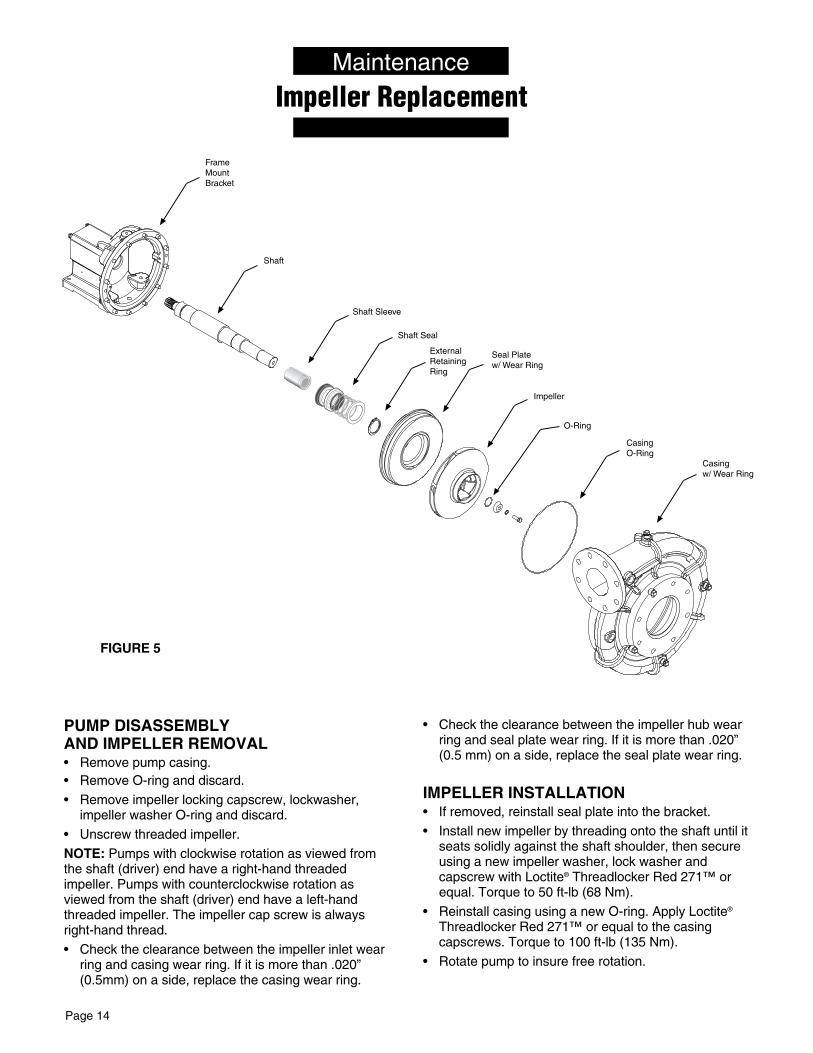
PUMP DISASSEMBLY AND IMPELLER REMOVAL• Remove pump casing.• Remove O-ring and discard.
• Remove impeller locking capscrew, lockwasher, impeller washer O-ring and discard.
• Unscrew threaded impeller.
NOTE: Pumps with clockwise rotation as viewed from the shaft (driver) end have a right-hand threaded impeller. Pumps with counterclockwise rotation as viewed from the shaft (driver) end have a left-hand threaded impeller. The impeller cap screw is always right-hand thread.
• Check the clearance between the impeller inlet wear ring and casing wear ring. If it is more than .020” (0.5mm) on a side, replace the casing wear ring.
• Check the clearance between the impeller hub wear ring and seal plate wear ring. If it is more than .020” (0.5 mm) on a side, replace the seal plate wear ring.
IMPELLER INSTALLATION• If removed, reinstall seal plate into the bracket.
• Install new impeller by threading onto the shaft until it seats solidly against the shaft shoulder, then secure using a new impeller washer, lock washer and capscrew with Loctite® Threadlocker Red 271™ or equal. Torque to 50 ft-lb (68 Nm).
• Reinstall casing using a new O-ring. Apply Loctite® Threadlocker Red 271™ or equal to the casing capscrews. Torque to 100 ft-lb (135 Nm).
• Rotate pump to insure free rotation.
FIGURE 5
Shaft Seal
Shaft
Casing w/ Wear Ring
Frame Mount Bracket
Seal Plate w/ Wear Ring
Impeller
Casing O-Ring
O-Ring
Shaft Sleeve
External Retaining Ring
6635 0812

Page 15
Mechanical Seal Maintenance/ReplacementMaintenance
Installing New Seal
MECHANICAL SEAL REPLACEMENT1. Remove pump casing.
2. Remove O-ring and discard.
3. Remove impeller locking capscrew, lockwasher, impeller washer O-ring and discard.
4. Unscrew threaded impeller.
NOTE: Pumps with clockwise rotation as viewed from the shaft (driver) end have a right-hand threaded impeller. Pumps with counterclockwise rotation as viewed from the shaft (driver) end have a left-hand threaded impeller. The impeller cap screw is always right-hand thread.
5. Remove the seal retaining ring and pull the rotating part of the seal off the shaft.
6. Remove the 2 capscrews holding the seal plate in place.
7. Pull the seal plate out until it clears the shaft, bringing the stationary part of the seal out with it. Tap the seal out of the seal plate and clean the seal cavity.
8. Inspect shaft sleeve, replace if necessary.
9. Install the new stationary seal in the seal cavity.
• Apply a small amount of mineral oil to the O-ring or cup seat of the stationary seal.
• Use the seal installation tool to press the stationary seal into place. (See FIGURE 6).
• Do not damage the seal face!
10. Reinstall the seal plate. Hold in place with 2 capscrews.
• Cover all shaft threads with the seal installation bull-nose tool to protect the seal during installation.
• Apply a small amount of mineral oil to the inside diameter of the rubber ring in the rotating seal and to the outside of the shaft sleeve and the outside of the seal assembly tool.
11. After lubricating the rotating part of the seal, slide it onto the shaft and sleeve until it seats against the stationary (ceramic) part using the seal installation tool.
12. Compress the seal spring on the shaft sleeve and reinstall the seal retaining ring.
13. Re-install impeller by threading onto the shaft until it seats solidly against the shaft shoulder, then secure using a new impeller washer, lock washer and capscrew with Loctite® Threadlocker Red 271™ or equal. Torque to 50 ft-lb (68 Nm).
• Reinstall casing using a new O-ring. Apply Loctite® Threadlocker Red 271™ or equal the casing capscrews. Torque to 100 ft-lb. (135 nm).
• Rotate pump to insure free rotation.
FIGURE 6 FIGURE 7
Polished Face upCardboard washer(Supplied with seal)
6064 0609
Shaft Seal
Shaft
Casing w/ Wear Ring
Frame Mount Bracket
Seal Plate w/ Wear Ring
Impeller
Casing O-Ring
O-Ring
Shaft Sleeve
External Retaining Ring
6636 0812

Page 16
Shaft Maintenance/ReplacementMaintenance
GENERAL• Shaft assembly of bearing frame pumps should
be disassembled annually to inspect for worn parts, cleaning, and re-greasing. More importantly, the pump’s shaft sleeve and bearings should be inspected for pitting. Replace worn components as needed.
PUMP DISASSEMBLY• Remove packing gland and packing arrangement, if
equipped. (Refer to packing ring replacement)
• Remove pump casing and impeller. (Refer to impeller replacement)
• Remove seal plate and water slinger.
• Remove outer bearing cap and slide shaft assembly from bearing bracket.
• Remove inner and outer grease seals from bearing bracket and bearing cap and discard.
• Clean and inspect all components.
FIGURE 8
SHAFT INSTALLATION• Thoroughly steam clean or solvent wash the bearing
cavity of bracket to remove old grease and dirt. Check surface of bracket for cracks, extreme corrosion, or other defects.
• Install new inner and outer grease seals in the bearing bracket and bearing cap. Lubricate with oil.
• Pack bearings with a lithium-based NLGI No. 2 extra pressure ball bearing grease. Force enough grease into each bearing to fill internal space between the races.
• Coat the bearing bores of bracket and the inboard grease seal with oil. Orient shaft assembly in the direction shown in FIGURE 8. Slide shaft and bearing assembly into bearing bracket. Do not force together! Slide shaft until the first bearing makes contact with the bracket. Carefully align bearing with the bearing bore and press or tap bearing assembly into place. Do not use excessive force!
NOTE: Be sure bearing bores and bracket areas are clean and free of contamination or early bearing failure may occur.
• Reinstall outer bearing cap and oil seal.
• Apply Loctite® Threadlocker Red 271™ or equal to capscrews. Torque to 50 ft-lb (68 Nm).
• Rotate pump by hand 10-12 rotations.
• Reassemble pump parts and reinstall unit to piping system.
• To install Shaft Sleeve, refer to Shaft Sleeve/Installation Replacement procedure.
Shaft Sleeve
Roller Bearing
Shaft
Ball Bearing
Water Slinger
Shaft Seal
External Retaining Ring
6586 0712

Page 17
TroubleshootingMaintenance
Hydraulic Drive Pump
CAUSE CORRECTIVE ACTION
I. ENGINE
A. Speed too low Refer to driver manufacturer’s manual.
B. Rotating and/or Refer to driver manufacturer’s manual. reciprocating parts drag
C. Speed too high Refer to pump and driver power curves; Adjust.
D. Loose or broken parts Refer to driver manufacturer’s manual.
E. Improper adjustment Adjust per driver manufacturer’s manual.
II. MECHANICAL
A. Flow through pump completely or Locate and remove obstruction. Refer to repair instructions partially obstructed for disassembly.
B. Wrong direction of rotation See manufacturer’s instructions for reversing driver.
C. Pump not primed Reprime; Inspect suction system for air leaks.
D. Internal leakage Check impeller for wear of controlled clearances (See repair instructions).
E. Loose parts Inspect. Repair.
F. Stuffing box not properly adjusted Adjust gland.
III. SYSTEM
A. Pressure required by system at design Compare pump pressure and flow rate against pump characteristic curve. flow rate exceeds pressure rating of pump Check for closed or partially closed valve in discharge piping system. Reduce system pressure requirement. Increase pressure capability of pump.
B. Obstruction in suction piping Locate and remove obstruction.
C. Pressure rating of pump exceeds pressure Compare pump pressure and flow rate against pump characteristic curve. requirement of system at design flow rate Inspect discharge piping system for breaks, leaks, open by-pass valves, etc. If necessary, reduce flow rate by partially closing discharge valve.
PROBABLE CAUSE
SYMPTOM GROUP I GROUP II GROUP III
DRIVER MECHANICAL SYSTEM
A B C D E F A B C D E F A B C
Pump runs, but no water delivered X X X X X
Not enough water delivered X X X X X X X
Not enough pressure X X X X X X X
Excessive vibration X X X X X X X X
Abnormal noise X X X X X X X X X X
Pump stops X X X X
Overheating X X X X X X X X X

Page 18 F00637
WarrantyBerkeley
Limited WarrantyBERKELEY warrants to the original consumer purchaser (“Purchaser” or “You”) of the products listed below, that they will be free from defects in material and workmanship for the Warranty Period shown below.
Product Warranty Period
Water Systems:
Water Systems Products — jet pumps, small centrifugal pumps, submersible pumps and related accessories
whichever occurs first: 12 months from date of original installation, or 18 months from date of manufacture
Pro-Source™ Composite Tanks 5 years from date of original installation
Pro-Source™ Steel Pressure Tanks 5 years from date of original installation
Pro-Source™ Epoxy-Lined Tanks 3 years from date of original installation
Sump/Sewage/Effluent Products12 months from date of original installation, or 18 months from date of manufacture
Agricultural/Commercial:
Centrifugals – close-coupled motor drive, frame mount, SAE mount, engine drive, VMS, SSCX, SSHM, solids handling, submersible solids handling
12 months from date of original installation, or 24 months from date of manufacture
Submersible Turbines, 6” diameter and larger12 months from date of original installation, or 24 months from date of manufacture
Our limited warranty will not apply to any product that, in our sole judgement, has been subject to negligence, misapplication, improper installation, or improper maintenance. Without limiting the foregoing, operating a three phase motor with single phase power through a phase converter will void the warranty. Note also that three phase motors must be protected by three-leg, ambient compensated, extra-quick trip overload relays of the recommended size or the warranty is void.Your only remedy, and BERKELEY’s only duty, is that BERKELEY repair or replace defective products (at BERKELEY’s choice). You must pay all labor and shipping charges associated with this warranty and must request warranty service through the installing dealer as soon as a problem is discovered. No request for service will be accepted if received after the Warranty Period has expired. This warranty is not transferable.BERKELEY SHALL NOT BE LIABLE FOR ANY CONSEQUENTIAL, INCIDENTAL, OR CONTINGENT DAMAGES WHATSOEVER.THE FOREGOING LIMITED WARRANTIES ARE EXCLUSIVE AND IN LIEU OF ALL OTHER EXPRESS AND IMPLIED WARRANTIES, INCLUDING BUT NOT LIMITED TO IMPLIED WARRANTIES OF MERCHANTABILITY AND FITNESS FOR A PARTICULAR PURPOSE. THE FOREGOING LIMITED WARRANTIES SHALL NOT EXTEND BEYOND THE DURATION PROVIDED HEREIN.Some states do not allow the exclusion or limitation of incidental or consequential damages or limitations on the duration of an implied warranty, so the above limitations or exclusions may not apply to You. This warranty gives You specific legal rights and You may also have other rights which vary from state to state.This Limited Warranty is effective June 1, 2011 and replaces all undated warranties and warranties dated before June 1, 2011.
In the U.S.: BERKELEY, 293 Wright Street, Delavan, WI 53115 In Canada: 269 Trillium Dr., Kitchener, Ontario N2G 4W5

This page intentionally left blank
