lidar r s p c cu-b lecture 07. fundamentals of lidar remote sensing...
TRANSCRIPT

LIDAR REMOTE SENSING PROF. XINZHAO CHU CU-BOULDER, SPRING 2016
Lecture 07. Fundamentals of Lidar Remote Sensing (5) “Physical Processes in Lidar”
q Light interaction with objects (continued) Ø Polarization of light Ø Polarization in scattering q Comparison of lidar equations q Comparison of backscatter cross-sections q Light transmission through the atmosphere q Summary and question
1

LIDAR REMOTE SENSING PROF. XINZHAO CHU CU-BOULDER, SPRING 2016
Polarization of Light
2 https://www.youtube.com/watch?v=Q0qrU4nprB0
Ø Light, as a photon stream, is also an electromagnetic wave - “Wave-particle duality”. It is a transverse EM wave. Ø There are both electric and magnetic fields associated with the light wave vector. The electric field E defines the polarization of light.

LIDAR REMOTE SENSING PROF. XINZHAO CHU CU-BOULDER, SPRING 2016
Polarization of Light
3
Ø For every single photon regarded as a plane wave, its complex amplitude vector can be written as For unpolarized light the phases ϕx and ϕy are uncorrelated and their difference fluctuates statistically. For linearly polarized light in x, Aoy= 0; in a direction α against x, ϕx = ϕy and tanα = Aoy/Aox. For circular polarization Aox = Aoy and ϕx = ϕy ± π/2. Ø The different states of polarization can be characterized by their Jones vectors, which are defined as where the normalized vectore {a, b} is the Jones vector. Ø The Jones representation shows its advantages when we consider the transmission of light through optical elements such as polarizers, wave plates, or beam splitters that can be described by 2x2 Jones matrices. Ø The polarization state of the transmitted light is then obtained by multiplication of the Jones vector of the incident wave by the Jones matrix of the optical element. Ø Ex and Ey form the orthogonal basis.
€
! E =! A oei(ωt−kz)
€
! A o =
Aoxeiφx
Aoyeiφy
# $ %
& %
' ( %
) %
€
! E =
E x
Ey
" # $
% & '
=! E ⋅
ab" # $
% & ' ⋅ ei(ωt−kz)
€
! E t =
E xt
Eyt
" # $
% & '
=a bc d(
) *
+
, - ⋅
E xo
Eyo
" # $
% & '
LIDAR REMOTE SENSING PROF. XINZHAO CHU CU-BOULDER, SPRING 2016
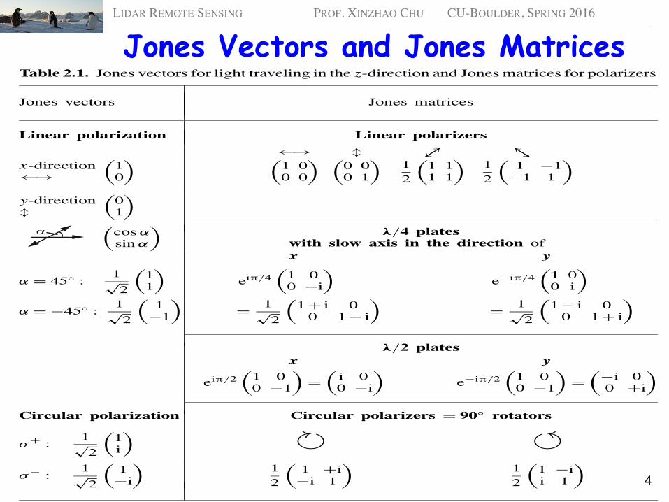
Jones Vectors and Jones Matrices
4
2.5 Polarization of Light 21
light with α = 45◦, for example, the amplitude A0 can be written as
A0 =!
A20x + A2
0y1√2
"11
#= |A0|
1√2
"11
#, (2.37)
while for circular polarization (σ+ or σ− light), we obtain
A(σ+)0 = 1√
2|A0|
"1i
#; A(σ−)
0 = 1√2
"1−i
#(2.38)
because exp(−iπ/2) = −i.The Jones representation shows its advantages when we consider the trans-
mission of light through optical elements such as polarizers, λ/4 plates, orbeamsplitters. These elements can be described by 2×2 matrices, which are
Table 2.1. Jones vectors for light traveling in the z-direction and Jones matrices for polarizers
Jones vectors Jones matrices
Linear polarization Linear polarizers
←→ ↕ ↗↙ ↖↘
←→x-direction
$10
% $1 00 0
% $0 00 1
%12
$1 11 1
%12
$1 −1
−1 1
%
↕y-direction
$01
%
$cos αsin α
%λ/4 plates
with slow axis in the direction ofx y
α = 45◦ : 1√2
$11
%eiπ/4
$1 00 −i
%e−iπ/4
$1 00 i
%
α = −45◦ : 1√2
$1
−1
%= 1√
2
$1+ i 0
0 1− i
%= 1√
2
$1− i 0
0 1+ i
%
λ/2 platesx y
eiπ/2$
1 00 −1
%=
$i 00 −i
%e−iπ/2
$1 00 −1
%=
$−i 00 +i
%
Circular polarization Circular polarizers = 90◦ rotators
σ+ : 1√2
$1i
% ! "σ− : 1√
2
$1−i
%12
$1 +i−i 1
%12
$1 −ii 1
%

LIDAR REMOTE SENSING PROF. XINZHAO CHU CU-BOULDER, SPRING 2016
Stokes Vectors and Mueller Matrices
5
Ø Jones vectors and Jones matrices are used in laser spectroscopy to describe the polarization state of light, which is usually coherent light. They are good descriptions of the single photon behaviors. Ø Stokes vectors and Mueller Matrices are formulated to represent incoherent (and coherent) light consisting of many photons, in terms of its total intensity (I), degree of polarization (p), and polarization ellipse.

LIDAR REMOTE SENSING PROF. XINZHAO CHU CU-BOULDER, SPRING 2016
Stokes Vectors and Mueller Matrices
6
!"#$%&'(%)"#*&
!!"#"
#
$
%$
+#",-'./"%/&0"1
2#*03#/",-'4567',/8'(%*"0),-'4967'./"%/&0"1
5:;<'4567',/8'9:;<'4967'./"%/&0"1
=%>"'2,/8'?0*)@-,*'4567',/8'A0BC"'2,/8'
?0*)@-,*'4967'./"%/&0"1
!"#$%&!'()!*+''!!!!!!!!,
%!&%!
Ø Stokes parameters do not form a preferred basis of the space, but rather were chosen for easy to be measured or calculated.
Linearly polarized (horizontal)
Linearly polarized (vertical)
Linearly polarized
(+45°)
Linearly polarized
(-45°)
Right-hand circularly polarized
Left-hand circularly polarized
Unpolarized

LIDAR REMOTE SENSING PROF. XINZHAO CHU CU-BOULDER, SPRING 2016
Polarization Lidar Equation
!!
! "
!#$%
&" #$
&"%$
"!'""
!"#$%&'(%)"#*'+,-.*'/01.",#2'3!(+/4'
&&()! " " "*
! '# ( %(&& "#&" %$ # ( %
5%.&1*%-'62"%2&,"789:#"#2';#12"&
!).""%*%*
<=",).>'!7&"%?
@*.2&?,&&,#2
&"%$ # ( %($ %&)#)# ( %+(*
(# %'()# # ( %!#&+ , -&+ . - ( %'()## ( %$'&
&" #$,&" /*
A>>'?."*,)%&'.*%'51%>>%*'?."*,)%&'":."').2'B%'
.2.>7C%-'1&,2D'+1E;:,=?.2'F%)#?=#&,",#2
!"#$%&!'()!*+''!!!!!!!!,
q Obeying the same physics picture of lidar remote sensing as scalar lidar equations, polarization lidar equation uses Stockes vectors and Mueller matrices to describe the polarization states and changes along with the instrument properties on polarization, etc. Due to the matrix calculation, the polarization lidar equation is written from right to left.

LIDAR REMOTE SENSING PROF. XINZHAO CHU CU-BOULDER, SPRING 2016
Polarization in Scattering q Depolarization is the phenomenon that the scattered photons possess
polarizations different than that of the original incident laser photons. Usually the incident laser beam has a linear polarization. Depolarization means that the return photons may have polarization other than this linear polarization, e.g., linear polarizations in other directions, or elliptical polarization.
q Note that every photon possesses certain polarization, i.e., every photon is polarized. Non-polarized light or depolarized light is talked about on the statistical point of view of a large number of photons.
q The range-resolved linear depolarization ratio is defined from lidar or optical observations as below in many lidar applications. Detailed sophisticated treatment of lidar depolarization needs to consider the optical matrix for polarization.
8
€
δ(R) =P⊥P||
=I⊥I||
where P and I are the light power and intensity detected.

LIDAR REMOTE SENSING PROF. XINZHAO CHU CU-BOULDER, SPRING 2016
Depolarization in Scattering
9
q Rayleigh scattering from air molecules can cause depolarization but only a few percent or less.
q Mie scattering from spherical particles at exactly 180° will not introduce depolarization.
q Depolarization can be resulted from (1) Spherical particle scattering at near 180° but not exact (2) Non-spherical particle shape (true for both aerosol/cloud and
atmosphere molecules) (3) Inhomogeneous refraction index (4) Multiple scattering inside fog, cloud or rain.

LIDAR REMOTE SENSING PROF. XINZHAO CHU CU-BOULDER, SPRING 2016
Scattering, Absorption, Fluorescence
Tran
scei
ver
λON, λOFF
10
ON OFF
Abso
rption
Lin
e
λ
Cabannes
PR Raman
Rayleigh
VR Raman
Mie
hν hν = Ek-Ei Ek
Ei Absorption & Resonance
Fluorescence Differential Absorption

LIDAR REMOTE SENSING PROF. XINZHAO CHU CU-BOULDER, SPRING 2016
Rayleigh Backscatter Coefficient
€
βRayleigh (λ ,z,θ = π) = 2.938×10⁻³² P(z)T (z)
⋅1
λ4.0117m−1sr−1( )
€
β(θ) =βT4π
P(θ) =βT4π
×0.7629× (1+0.9324cos2θ)
P in mbar and T in Kelvin at altitude z, λ in meter.
Rayleigh Backscatter Cross Section
€
dσm (λ)dΩ
= 5.45 ⋅ 550λ
&
' (
)
* + 4×10⁻³² m2sr−1( )
where λ is the wavelength in nm.
q For Rayleigh lidar, λ = 532 nm, ð 6.22 x 10⁻³² m2sr-1 11

LIDAR REMOTE SENSING PROF. XINZHAO CHU CU-BOULDER, SPRING 2016
Scattering Form of Lidar Equation q Rayleigh, Mie, and Raman scattering processes are instantaneous scattering processes, so there are no finite relaxation effects involved, but infinitely short duration. q For Rayleigh and Mie scattering, there is no frequency shift when the atmospheric particles are at rest. The lidar equation is written as
€
NS (λ ,R) =PL (λ)Δthc λ
$
% &
'
( ) β(λ ,R)ΔR( ) A
R2$
% &
'
( ) T 2(λ ,R) η(λ)G(R)( )+NB
€
NS (λ ,R) =PL (λL )Δthc λL
$
% &
'
( ) β(λ ,λL ,R)ΔR( ) A
R2$
% &
'
( ) T (λL ,R)T (λ ,R)( ) η(λ ,λL )G(R)( )+NB
€
λ ≠ λL , pi (λ) ≠1, pi (λ) <1
q For Raman scattering, there is a large frequency shift. Raman lidar equation may be written as
€
T (λ ,R) = exp − α(λ ,r)dr0
R∫&
' ( ) * + 12

LIDAR REMOTE SENSING PROF. XINZHAO CHU CU-BOULDER, SPRING 2016
Differential Absorption/Scattering Form of Lidar Equation
€
NS (λon ,R) = NL (λon ) βsca (λon ,R)ΔR[ ] AR2
%
& '
(
) * exp −2 α (λon , - r )d - r
0
z∫/
0 1 2 3 4
×exp −2 σabs(λon , - r )nc ( - r )d - r 0
z∫/
0 1 2 3 4 η(λon )G(R)[ ] + NB
q For the laser with wavelength λon on the molecular absorption line
€
NS (λoff ,R) = NL (λoff ) βsca (λoff ,R)ΔR[ ] AR2
%
& '
(
) * exp −2 α (λoff , - r )d - r
0
z∫/
0 1 2 3 4
×exp −2 σabs(λoff , - r )nc ( - r )d - r 0
z∫/
0 1 2 3 4 η(λoff )G(R)[ ] + NB
q For the laser with wavelength λoff off the molecular absorption line
€
Δσ abs(R) =σ abs(λON ,R) −σ abs(λOFF ,R)
q Differential absorption cross-section
13

LIDAR REMOTE SENSING PROF. XINZHAO CHU CU-BOULDER, SPRING 2016
Fluorescence Form of Lidar Equation
€
NS (λ ,R) =PL (λ)Δthc λ
$
% &
'
( ) σ eff (λ ,R)nc (z)RB(λ)ΔR( ) A
4πR2$
% &
'
( ) Ta
2(λ ,R)Tc2(λ ,R)( ) η(λ)G(R)( )+NB
€
Tc(R) = exp − σeff (λ, % r )nc( % r )d % r Rbottom
R∫( ) = exp − αc(λ, % r )d % r Rbottom
R∫( )q Here, α(λ,R) is the extinction coefficient caused by the absorption.
€
αc (λ ,R) =σ eff (λ ,R)nc (R)
q Here, TC(R) is the transmission caused by the constituent absorption.
q Resonance fluorescence and laser-induced-fluorescence are NOT instantaneous processes, but have delays due to the radiative lifetime of the excited states. It contains two steps - absorption and then emission.
q The lidar equation in fluorescence form is given by
14

LIDAR REMOTE SENSING PROF. XINZHAO CHU CU-BOULDER, SPRING 2016
Backscatter Cross-Section Comparison Physical Process Backscatter
Cross-SectionMechanism
Mie (Aerosol) Scattering 10-8 - 10-10 cm2sr-1 Two-photon processElastic scattering, instantaneous
Atomic Absorption and Resonance Fluorescence
10-13 cm2sr-1 Two single-photon process (absorption and spontaneous emission)Delayed (radiative lifetime)
Molecular Absorption 10-19 cm2sr-1 Single-photon process
Fluorescence from molecule, liquid, solid
10-19 cm2sr-1 Two single-photon processInelastic scattering, delayed (lifetime)
Rayleigh Scattering(Wavelength Dependent)
10-27 cm2sr-1 Two-photon processElastic scattering, instantaneous
Raman Scattering(Wavelength Dependent)
10-30 cm2sr-1 Two-photon processInelastic scattering, instantaneous
15 The total absorption cross-section is 4π times backscatter cross-section.
LIDAR REMOTE SENSING PROF. XINZHAO CHU CU-BOULDER, SPRING 2016
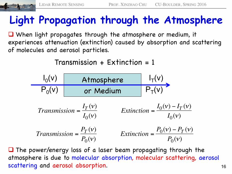
Light Propagation through the Atmosphere q When light propagates through the atmosphere or medium, it experiences attenuation (extinction) caused by absorption and scattering of molecules and aerosol particles.
Transmission + Extinction = 1
16
Atmosphere or Medium
I0(ν) IT(ν)
€
Transmission =IT (ν)I0(ν)
Extinction =I0(ν) − IT (ν)
I0(ν)
q The power/energy loss of a laser beam propagating through the atmosphere is due to molecular absorption, molecular scattering, aerosol scattering and aerosol absorption. €
Transmission =PT (ν)P0(ν)
Extinction =P0(ν) − PT (ν)
P0(ν)
P0(ν) PT(ν)

LIDAR REMOTE SENSING PROF. XINZHAO CHU CU-BOULDER, SPRING 2016
Atomic and Molecular Absorption
17
Molecules I0(λ) IT(λ)
€
dI(λ) = −I(λ)α(λ)dz = −Iσik (λ)(Ni − Nk )dz
hν hν = Ek-Ei Ek
Ei Ø The intensity change dI of a light propagating through an absorbing sample is determined by the absorption coefficient αmol,abs in the following manner:
is absorption coefficient caused by transition Ei à Ek Here, σik is the absorption cross section, Ni and Nk are the populations on the energy levels of Ei and Ek, respectively.
Ø If ΔN = Ni – Nk is independent of the light intensity I, the absorbed intensity dI is proportional to the incident intensity I (linear absorption). Solving the above equation, we obtain
€
α(λ) =σik (λ)(Ni − Nk )
€
I(λ,z) = I0 exp − σ ik (λ)(Ni − Nk )dz0z∫&
' ( ) * + è
€
I(λ,z) = I0e−σ (λ )(Ni −Nk )L = I0e
−α (λ )L
-- Lambert-Beer’s Law
L

LIDAR REMOTE SENSING PROF. XINZHAO CHU CU-BOULDER, SPRING 2016
Light Transmission through the Atmosphere
18
€
Transmission T(λ,R) =IT (λ,R)I0(λ)
= exp − α(λ,r)dr0R∫&
' ( ) * + = exp − σ (λ)ΔN(r)dr
0R∫&
' ( ) * + (5.6)
Taken from http://speclab.cr.usgs.gov/PAPERS.refl-mrs/refl4.html Ø Absorption cross section, scatter concentration, and path length all matter to the light transmission. Zenith angle is related to path length. Ø MODTRAN provides a good resource for calculating light transmission.
LIDAR REMOTE SENSING PROF. XINZHAO CHU CU-BOULDER, SPRING 2016
Light Transmission through the Atmosphere
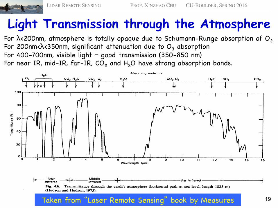
19 Taken from “Laser Remote Sensing” book by Measures
For λ<200nm, atmosphere is totally opaque due to Schumann-Runge absorption of O2 For 200nm<λ<350nm, significant attenuation due to O3 absorption For 400-700nm, visible light − good transmission (350-850 nm) For near IR, mid-IR, far-IR, CO2 and H2O have strong absorption bands.

LIDAR REMOTE SENSING PROF. XINZHAO CHU CU-BOULDER, SPRING 2016
Molecular Absorption, Molecular Scattering, Aerosol Scattering, and Aerosol Absorption
20
€
α = −dI /Idz
Ø Here, the scattering extinction coefficients are the scattering coefficient integrated over the entire 4π solid angle, as all-direction scatterings are attenuation to the laser light.
€
α = αmol,abs +αmol,sca +αaer,sca +αaer,abs
Ø The extinction coefficient has the meaning of the percentage change of laser intensity per unit distance Ø In approximation of constant α over distance, the laser transmission is given by
€
T = e−αL
Ø Total scattering cross section of atm molecular for z < 100 km is given by
€
σm,total (λ) = 4.56⋅ 550λ(nm)%
& '
(
) * 4×10⁻³¹m2
Ø Given a sea-level Nm=2.55×1019 cm-3, the molecular scattering extinction coefficient is -- a sea-level visibility exceeding 250 km!
€
αm = 0.0116 km−1
Ø The main attenuation of mid-visible light is due to the presence in the atmosphere of various solid and liquid particles – aerosols.

LIDAR REMOTE SENSING PROF. XINZHAO CHU CU-BOULDER, SPRING 2016
Atmospheric Attenuation Coefficient
21
Taken from “Laser Remote
Sensing” book by Measures
Empirical formula for atmospheric extinction coefficient
€
κMie(λ) ≈3.91Rv
550λ
%
& '
(
) * qkm−1
q = 0.585Rv1/3 for Rv ≤ 6km

LIDAR REMOTE SENSING PROF. XINZHAO CHU CU-BOULDER, SPRING 2016
General Case of Light Transmission
22
€
T(ν,z) =IT (ν,z)I0(ν)
= exp − α(ν,z)dzz1
z2∫& ' (
) * +
= exp − σ (ν,z)ΔN(z)dzz1
z2∫& ' (
) * +
Ø Transmission for single-frequency radiation propagation through an inhomogeneous medium
Ø Transmission for the general case of radiation propagation through an inhomogeneous medium in the spectral interval [ν1, ν2]:
€
T(z) =IT (ν,z)dνν1
ν 2∫I0(ν)dνν1
ν 2∫=
I0(ν)exp − σ(ν,z)ΔN(z)dzz1
z2∫' ( )
* + , dν
ν1
ν 2∫
I0(ν)dνν1
ν 2∫
z1 = 0 z2 = z
€
I0(ν)
€
IT (ν,z)
€
I0(ν)dνν1
ν 2∫
€
IT (ν,z)dνν1
ν 2∫Radiation propagation through an medium

LIDAR REMOTE SENSING PROF. XINZHAO CHU CU-BOULDER, SPRING 2016
General Case of Light Transmission
23
Ø Extinction/Attenuation for the general case of radiation propagation through an inhomogeneous medium in the spectral interval [ν1, ν2]:
€
A(z) =1−T(z) =I0(ν) 1− exp − σ(ν,z)ΔN(z)dz
z1
z2∫' ( )
* + ,
- . /
0 1 2 dν
ν1
ν 2∫
I0(ν)dνν1
ν 2∫
Ø In the case of homogeneous spectral dependence of the source intensity over the spectral interval [ν1, ν2]:
€
T(z) = exp − σ(ν,z)ΔN(z)dzz1
z2∫' ( )
* + , dν
ν1
ν 2∫ (ν2 −ν1)
€
T(z) = I0(ν)exp −ΔNσ (ν)L[ ]dνν1
ν 2∫ I0(ν)dνν1
ν 2∫Ø In the case of homogeneous absorbing medium:
€
T(z) = exp −ΔNσ(ν)L[ ]dνν1
ν 2∫ (ν2 −ν1)
Ø In the case of homogeneous absorbing medium and homogeneous source spectral dependence:

LIDAR REMOTE SENSING PROF. XINZHAO CHU CU-BOULDER, SPRING 2016
Summary (1) q Numerous physical processes are involved in lidars, including the interactions between light and objects, and the light transmission through the atmosphere or other medium. q The fundamentals to understand atomic structures and energy levels are related to the interactions inside and outside an atom, including electrostatic interactions, electron spin, spin-orbit angular momentum coupling, nuclear spin, mass and volume, external fields, etc. Molecular structures and energy levels further include interactions among atoms within a molecule. Liquids and solids further involve intermolecular interactions. q Main physical processes for interactions between light and objects include elastic and inelastic scattering, absorption and differential absorption, resonance fluorescence, laser induced fluorescence, Doppler effects, Boltzmann distribution, reflection from surfaces, multiple scattering, and depolarization. There are large differences in scattering cross sections for various physical processes involved in lidar.
24

LIDAR REMOTE SENSING PROF. XINZHAO CHU CU-BOULDER, SPRING 2016
Summary (2) q Doppler effects, Boltzmann distribution, polarization properties, etc, all can be utilized in lidar applications to infer atmospheric parameters like wind, temperature, aerosol properties, etc. Multiple scattering should be considered in lower atmosphere studies, especially for cloud and aerosol research. q Light transmission through the atmosphere is mainly attenuated by molecular and aerosol absorption and scattering. When wavelengths fall in a strong molecular absorption bands, the attenuation could be significant, e.g., UV light below 200 nm or mid-infrared around 6.2 μm – the Earth’s atmosphere becomes total opaque. The visibility of atmosphere is mainly dominated by aerosol scattering and absorption, therefore varies dramatically under different meteorological conditions.
25
q Molecular oxygen O2 in the Earth’s atmosphere has strong absorptions centered at 760 nm and 687 nm with O2 A- and B-bands, respectively.

LIDAR REMOTE SENSING PROF. XINZHAO CHU CU-BOULDER, SPRING 2016
Summary (3) and Questions q Interactions between light and objects are the basis of lidar remote sensing, because it is these interactions that modify light properties so that the light can carry away the information of the objects. q Understanding these physical processes precisely is the key to successful lidar simulations, design, development, and applications. Lidar equations are developed according to these physical processes. q Lidar equation may change its form to best fit for each particular physical process and lidar application.
26
Our Textbook – Chapter 3 for elastic scattering and polarization Chapter 4 for differential absorption Chapters 5 & 7 for resonance fluorescence, Boltzmann, Doppler Chapter 6 for laser-induced fluorescence Laser monitoring of the atmosphere (Hinkley) Ch. 3 and 4 Laser Remote Sensing (Measures) Chapter 4 Lidar (Ed. Weitkamp) Chapters 2 and 3
Can you use the Boltzmann distribution in pure rotational Raman spectroscopy to measure temperatures? If yes, how?