libraries for building automation - wago onlinecatalog · libraries for building automation ......
TRANSCRIPT

Libraries for Building Automation
Function Block Description for DALI Multi-Master Module 753-647
Last Update: 08.08.2012

Subject to design changes WAGO Kontakttechnik GmbH & Co. KG P.O. box 2880 • D-32385 Minden Phone: 05 71 / 8 87-0 E-Mail: [email protected] Copyright © 2012 Hansastr. 27 • D-32423 Minden Fax: 05 71 / 8 87-169 Web:http://www.wago.com
2
Copyright 2012 by WAGO Kontakttechnik GmbH & Co. KG All rights reserved.
WAGO Kontakttechnik GmbH & Co. KG Hansastraße 27 D-32423 Minden
Phone: +49 (0) 571/8 87 – 0 Fax: +49 (0) 571/8 87 – 1 69
E-Mail: [email protected]
Web: http://www.wago.com
Technical Support Phone: +49 (0) 571/8 87 – 555 Fax: +49 (0) 571/8 87 – 8555
E-Mail: [email protected]
Every conceivable measure has been taken to ensure the accuracy and completeness of this documentation. However, as errors can never be fully excluded, we always appreciate any information or suggestions for improving the documentation.
We wish to point out that the software and hardware names, as well as the trademarks of companies used and/or mentioned in the present manual, are generally protected by trademark or patent.

Content
Subject to design changes WAGO Kontakttechnik GmbH & Co. KG P:O. box 2880 • D-32385 Minden Phone: 05 71 / 8 87-0 E-Mail: [email protected] Copyright © 2012 Hansastr. 27 • D-32423 Minden Fax: 05 71 / 8 87-169 Web:http://www.wago.com
3
WAGO-I/O-PRO Library for DALI Multi-Master Module 753-647
Content
Important Notes 5
Copyright ..................................................................................................... 5 Personnel Qualification................................................................................ 5 Intended use ................................................................................................. 5 Scope of Validity ......................................................................................... 6
01 Communication 7
DALI Master Module IPC (FbMaster753_647_IPC) .................................. 7
02 Configuration 9
DALI Configuration (PrgDALIConfig)....................................................... 9 Addressing the Control Gears (FbAddressingControlGears) .................... 10 Localizing the Control Gears (FbIdentifyControlGear) ............................ 14 Control Gear settings (FbSettingsControlGear)......................................... 16 Group Configuration (FbGroupConfig)..................................................... 18 Scene Configuration (FbSceneConfig) ...................................................... 20 Status Query of the Control Gears (FbStatusControlGear) ....................... 22
03 Switching 24
Latching Relay (FbDaliLatchingRelay)..................................................... 24 ON/OFF Switch (FbDaliSwitchOnOff)..................................................... 26
04 Dimming 28
Dimmer Double Button (FbDaliDimmDoubleButton).............................. 28 Dimmer Single Button (FbDaliDimmSingleButton) ................................. 31
05 Light Control 34
Constant Light Control (FbDaliConstantLightControl)............................. 34 Constant Light Control Settings (FbDaliConfigConstantLightControl).... 41
06 Scenes 42
Scene Recall (FbDaliRecallScene) ............................................................ 42

Table of Contents
Subject to design changes WAGO Kontakttechnik GmbH & Co. KG P:O. box 2880 • D-32385 Minden Phone: 05 71 / 8 87-0 E-Mail: [email protected] Copyright © 2012 Hansastr. 27 • D-32423 Minden Fax.: 05 71 / 8 87-169 Web:http://www.wago.com
4
07 General 44
Send Direct Dim Level (FbDaliSendDimmValue).................................... 44 Send individual DALI commands (FbDaliControlGearCommands) ........ 46 Call up macros in the module (FbDaliMacroCommands) ......................... 48
08 Conversions 50
DALI Dimming Level -> Dimming Level Percent (FuPercentDimmValue)50 Dimming Level Percent -> DALI Dimming Level (FuDaliDimmValue) . 50
Appendix 51
Numeric code "bFeedback" ....................................................................... 51 Command set for FbDaliControlGearCommands ..................................... 52 Command set for FbDaliMacroCommands ............................................... 54 Reset values ............................................................................................... 61 Fade Time and Fade Rate .......................................................................... 61

Important Notes
Subject to design changes WAGO Kontakttechnik GmbH & Co. KG P:O. box 2880 • D-32385 Minden Phone: 05 71 / 8 87-0 E-Mail: [email protected] Copyright © 2012 Hansastr. 27 • D-32423 Minden Fax: 05 71 / 8 87-169 Web:http://www.wago.com
5
Important Notes To ensure fast installation and start-up of the units, we strongly recommend that the following information and explanations are carefully read and adhered to.
Copyright
This document, including all figures and illustrations contained therein, is subject to copyright protection. Any use of this document that infringes upon the copyright provisions stipulated herein is prohibited. Reproduction, translation, electronic and phototechnical filing/archiving (e.g., photocopying), as well as any amendments require the written consent of WAGO Kontakttechnik GmbH & Co. KG, Minden, Germany. Non-observance will involve the right to assert damage claims. WAGO Kontakttechnik GmbH & Co. KG reserves the right to make any alterations or modifications that serve to increase the efficiency of technical progress. WAGO Kontakttechnik GmbH & Co. KG owns all rights arising from the granting of patents or from the legal protection of utility patents. Third-party products are always mentioned without any reference to patent rights. Thus, the existence of such rights cannot be excluded.
Personnel Qualification
The use of the product described in this document is exclusively geared to specialists having qualifications in SPS programming, electrical specialists or persons instructed by electrical specialists who are also familiar with the appropriate current standards. WAGO Kontakttechnik GmbH & Co. KG assumes no liability resulting from improper action and damage to WAGO products and third-party products due to non-observance of the information contained in this document.
Intended use
For each individual application, the components are supplied from the factory with a dedicated hardware and software configuration. Modifications are only admitted within the framework of the possibilities documented in this document. All other changes to the hardware and/or software and the non-conforming use of the components entail the exclusion of liability on part of WAGO Kontakttechnik GmbH & Co. KG. Please send your requests for modified and new hardware or software configurations directly to WAGO Kontakttechnik GmbH & Co. KG.

Important Notes
Subject to design changes WAGO Kontakttechnik GmbH & Co. KG P:O. box 2880 • D-32385 Minden Phone: 05 71 / 8 87-0 E-Mail: [email protected] Copyright © 2012 Hansastr. 27 • D-32423 Minden Fax.: 05 71 / 8 87-169 Web:http://www.wago.com
6
Scope of Validity
This application note is based on the stated hardware and software from the specific manufacturer, as well as the associated documentation. This application note is therefore only valid for the described installation. New hardware and software versions may need to be handled differently.
Please note the detailed description in the specific manuals.

DALI Master Module IPC (FbMaster753_647_IPC)
Subject to design changes WAGO Kontakttechnik GmbH & Co. KG P:O. box 2880 • D-32385 Minden Phone: 05 71 / 8 87-0 E-Mail: [email protected] Copyright © 2012 Hansastr. 27 • D-32423 Minden Fax: 05 71 / 8 87-169 Web:http://www.wago.com
7
01 Communication
DALI Master Module IPC (FbMaster753_647_IPC)
WAGO-I/O-PRO Library Elements
Category: Building Automation
Name: FbMaster753_647_IPC
Type: Function Function block X Program
Name of library: WagoLibDALI_01.lib
Applicable to: See release note
Input parameter: Data type: Comment:
abIn_753_647 ARRAY[0..23] OF BYTE
Input array for DALI module 753-647
bModule_753_647 BYTE Specifies which DALI module is to be addressed at the controller. Counting is from left to right. Default setting = 1
xQuit BOOL Error message acknowledgement
Input/output parameter: Data type: Comment:
abOut_753_647 ARRAY[0..23] OF BYTE
Output array for DALI module 753-647
Output parameters: Data type: Comment:
bFeedback BYTE Response byte (see table 1 in the appendix)
Graphical illustration:
Function description:
The FbMaster753_647 function block is used as the interface for DALI Multi-Master module 753-647. All other function blocks communicate with the DALI module via this function block.
The corresponding DALI module is specified at the "bModule_753_647" input. Counting is from left to right.

DALI Master Module IPC (FbMaster753_647_IPC)
Subject to design changes WAGO Kontakttechnik GmbH & Co. KG P:O. box 2880 • D-32385 Minden Phone: 05 71 / 8 87-0 E-Mail: [email protected] Copyright © 2012 Hansastr. 27 • D-32423 Minden Fax.: 05 71 / 8 87-169 Web:http://www.wago.com
8
The "abIn_753_647" input and "abOut_753_647" output contain the input or output array for the data of the DALI module. The variables at these inputs must be linked to the corresponding hardware address.
Example:
abIn_753_647 = Input AT %IB0 : ARRAY [0..23] OF BYTE;
abOut_753_647 = Output AT %QB0 : ARRAY [0..23] OF BYTE;
The output "bFeedback" outputs a numeric code with the error message. Numeric codes are listed in Table 1 in the Appendix.
The error message can be acknowledged via a positive edge at the “xQuit“ input.
Note:
The FbMaster753_647_IPC function block must be called in the program sequence before all other DALI function blocks.
All DALI function blocks that communicate with this master must be called up in the same program task.
Only one DALI master module may be used per DALI module.
The function block switches the DALI Multi-Master module automatically into the full mode.

DALI Configuration (PrgDALIConfig)
Subject to design changes WAGO Kontakttechnik GmbH & Co. KG P:O. box 2880 • D-32385 Minden Phone: 05 71 / 8 87-0 E-Mail: [email protected] Copyright © 2012 Hansastr. 27 • D-32423 Minden Fax: 05 71 / 8 87-169 Web:http://www.wago.com
9
02 Configuration
DALI Configuration (PrgDALIConfig)
WAGO-I/O-PRO Library Elements
Category: Building Automation
Name: PrgDALIConfig
Type: Function Function block Program X
Name of library: WagoLibDALI_01.lib
Applicable to: See release note
Visualization templates: WagoLibDALI_01.exp
Graphical illustration:
Display:
Function description:
For the DALI configuration tool, the PrgDALIConfig program must be called once in the project. In addition, the associated visualization pages can be imported into the project via the WagoLibDALI_01.exp export file.

Addressing the Control Gears (FbAddressingControlGears)
Subject to design changes WAGO Kontakttechnik GmbH & Co. KG P:O. box 2880 • D-32385 Minden Phone: 05 71 / 8 87-0 E-Mail: [email protected] Copyright © 2012 Hansastr. 27 • D-32423 Minden Fax.: 05 71 / 8 87-169 Web:http://www.wago.com
10
Addressing the Control Gears (FbAddressingControlGears)
WAGO-I/O-PRO Library Elements
Category: Building Automation
Name: FbAddressingControlGears
Type: Function Function block X Program
Name of library: WagoLibDALI_01.lib
Applicable to: See release note
Input parameter: Data type: Comment:
xStartRandomAddressing BOOL A positive edge starts the random addressing of the DALI control gears.
xStartPhysicalSelection BOOL A positive edge starts the addressing of the Control Gears via the physical selection.
xStopAddressing BOOL A positive edge ends the addressing of the control gears prematurely.
typConfigAddressing typConfig Address ing
Selection of the different addressing options
.xRandomSetReset Value
BOOL With random addressing, all newly addressed control gears are set to their "reset values". Default setting = TRUE
.xRandomUnaddressed BOOL With random addressing, only control gears with no short address are readdressed. Default setting = TRUE
.xRandomChangeActualLevel
BOOL With random addressing, the current dimming level remains unchanged. Default setting = FALSE
.xPhysicalSetReset Value
BOOL With physical selection, all newly addressed control gears are set to their "reset values". Default setting = FALSE
.xPhysicalUnaddressed BOOL With physical selection, only control gears with no short address are readdressed. Default setting = TRUE
xDeleteShortAddress BOOL A positive edge deletes the selected "bDeleteShortAddress" short address.
bDeleteShortAddress BYTE Selection of the short address to be deleted
xResetValues BOOL A positive edget sets the control gears with the short address "bResetValues" to its "reset values".
bResetValues BYTE Selection of the control gears to be reset
xSyncDataBase BOOL A positive edge synchronizes the module-internal database.
xCentralOn BOOL A positive edge switches all control gears on.

Addressing the Control Gears (FbAddressingControlGears)
Subject to design changes WAGO Kontakttechnik GmbH & Co. KG P:O. box 2880 • D-32385 Minden Phone: 05 71 / 8 87-0 E-Mail: [email protected] Copyright © 2012 Hansastr. 27 • D-32423 Minden Fax: 05 71 / 8 87-169 Web:http://www.wago.com
11
xCentralOff BOOL A positive edge switches all control gears
off.
xQuit BOOL A positive edge acknowledges the fault message on the "bFeedback" output.
bModule_753_647 BYTE Specifies which DALI master module is to be addressed at the controller. Counting is from left to right. Default setting = 1
Return value: Data type: Comment:
xReady BOOL TRUE = communication deactivated FALSE = communication activated
bFeedback BYTE Response byte (see table 1 in the appendix)
Graphical illustration:

Addressing the Control Gears (FbAddressingControlGears)
Subject to design changes WAGO Kontakttechnik GmbH & Co. KG P:O. box 2880 • D-32385 Minden Phone: 05 71 / 8 87-0 E-Mail: [email protected] Copyright © 2012 Hansastr. 27 • D-32423 Minden Fax.: 05 71 / 8 87-169 Web:http://www.wago.com
12
Function description:

Addressing the Control Gears (FbAddressingControlGears)
Subject to design changes WAGO Kontakttechnik GmbH & Co. KG P:O. box 2880 • D-32385 Minden Phone: 05 71 / 8 87-0 E-Mail: [email protected] Copyright © 2012 Hansastr. 27 • D-32423 Minden Fax: 05 71 / 8 87-169 Web:http://www.wago.com
13
The FbAddressingControlGears is used to address the connected control gears. In addition, the short addresses can be deleted or the settings reset to the "reset values" via the module.
Random addressing with the following parameters is started with a positive edge on the "xStartRandomAddressing" input:
"typConfigAddressing.xRandomSetResetValue" TRUE = Each readdressed control gear is set to its "reset values" FALSE = All control gears retain their old configuration
"typConfigAddressing.xRandomUnaddressed" TRUE = Only control gears with no short address are readdressed FALSE = All control gears are readdressed
"typConfigAddressing.xRandomChangeActualLevel" TRUE = The dimming level is not changed while addressing FALSE = The dimming level is changed while addressing
Addressing with the following parameters is started with a positive edge on the "xStartPhysicalSelection" input:
"typConfigAddressing.xPhysicalSetResetValue" TRUE = Each readdressed control gear is set to its "reset values" FALSE = All control gears retain their old configuration
"typConfigAddressing.xPhysicalUnaddressed" TRUE = Only control gears with no short address are readdressed FALSE = All control gears are readdressed
The addressing routine is terminated prematurely with a positive edge on the "xStopAddressing" input.
If a positive edge is detected on the "xDeleteShortAddress" input, the short address is then deleted for the control gear selected on the "bDeleteShortAddress" input.
If a positive edge is detected on the "xResetValues" input, the control gear is reset to its "reset values" on the "bResetValues" input.
The module database is synchronized with a positive edge on the "xSyncDataBase" input.
The entire lighting is switched on or off with a positive edge on the "xCentralOn" or "xCentralOff" inputs.
The DALI module with which this function block must communicate is selected at input "bModule_753_647".
The "xReady" output signals whether the module is active. As long as "xReady" is FALSE, no further action is taken by the function block.
If there is fault message at the "bFeedback" output, it can be acknowledged by a positive edge on the "xQuit" input. Only after the fault is acknowledged can the module execute a new action.
Note:
Before addressing, all connected sensors are switched to "Passive Mode"(Sensors may not independently transmit DALI messages).
Once addressing is complete, the database is synchronized in the module and the sensors switced to "Indirect Mode"(The sensors can send their value only to the DALI-Multi Master module).

Localizing the Control Gears (FbIdentifyControlGear)
Subject to design changes WAGO Kontakttechnik GmbH & Co. KG P:O. box 2880 • D-32385 Minden Phone: 05 71 / 8 87-0 E-Mail: [email protected] Copyright © 2012 Hansastr. 27 • D-32423 Minden Fax.: 05 71 / 8 87-169 Web:http://www.wago.com
14
Localizing the Control Gears (FbIdentifyControlGear)
WAGO-I/O-PRO Library Elements
Category: Building Automation
Name: FbIdentifyControlGear
Type: Function Function block X Program
Name of library: WagoLibDALI_01.lib
Applicable to: See release note
Input parameter: Data type: Comment:
xReplaceShortAddress BOOL A positive edge replaces the "bCurrentShortAddress" short address with the "bNewShortAddress" short address.
bCurrentShortAddress BYTE Short address for localizating the control gears
bNewShortAddress BYTE New address when replacing the short addresses
xCentralOnxCentralOn BOOL A positive edge switches all control gears on.
xCentralOff BOOL A positive edge switches all control gears off.
xFlash BOOL As long as the input is active, the control gears flashes with the "bActualShortAddress" short address.
bFlashPeriod BYTE Flash period for the detection of the control gears Value range = 1 – 51 [s] Default setting = 1
xQueryShortAddress BOOL A positive edge determins the existing short addresses from the module database.
xQuit BOOL A positive edge acknowledges the fault message on the "bFeedback" output.
bModule_753_647 BYTE Specifies which DALI master module is to be addressed at the controller. Counting is from left to right. Default setting = 1
Return value: Data type: Comment:
xReady BOOL TRUE = communication deactivated FALSE = communication activated
bFeedback BYTE Response byte (see table 1 in the appendix)
axShortAddress ARRAY [0..63] OF BOOL
Indication of the existing control gear short addresses

Subject to design changes WAGO Kontakttechnik GmbH & Co. KG P:O. box 2880 • D-32385 Minden Phone: 05 71 / 8 87-0 E-Mail: [email protected] Copyright © 2012 Hansastr. 27 • D-32423 Minden Fax: 05 71 / 8 87-169 Web:http://www.wago.com
15
Graphical illustration:
Function description:
The FbIdentifyControlGear is used to identify and replace the control gear short addresses.
With a positive edge on the "xReplaceShortAddress" input, the "bCurrentShortAddress" short address is replaced with the "bNewShortAddress" short address. The "bCurrentShortAddress" short address must be available at least.
The entire lighting is switched on or off with a positive edge on the "xCentralOn" or "xCentralOff" inputs.
If the "xFlash" is activated, the control gear selected on the "bCurrentShortAddress" flashes for the "bFlashPeriod" flash period.
With a positive edge on the "xQueryShortAddress" input, the existing short addresses are queried from the module database and displayed at the "axShortAddress" output.
The DALI module with which this function block must communicate is selected at input "bModule_753_647".
The "xReady" output signals whether the module is active. As long as "xReady" is FALSE, no further action is taken by the function block.
If there is fault message at the "bFeedback" output, it can be acknowledged by a positive edge on the "xQuit" input. Only after the fault is acknowledged can the module execute a new action.

Control Gear settings (FbSettingsControlGear)
Subject to design changes WAGO Kontakttechnik GmbH & Co. KG P:O. box 2880 • D-32385 Minden Phone: 05 71 / 8 87-0 E-Mail: [email protected] Copyright © 2012 Hansastr. 27 • D-32423 Minden Fax.: 05 71 / 8 87-169 Web:http://www.wago.com
16
Control Gear settings (FbSettingsControlGear)
WAGO-I/O-PRO Library Elements
Category: Building Automation
Name: FbSettingsControlGear
Type: Function Function block X Program
Name of library: WagoLibDALI_01.lib
Applicable to: See release note
Input parameter: Data type: Comment:
bAddress BYTE Short address from 0 – 63 or broadcast
xGroup BOOL Selects short or group address: FALSE = short address or broadcast TRUE = group address Default setting = FALSE
xRead BOOL A positive edge causes reading of the configuration values.
xWrite BOOL A positive edge writs the configuration parameters to the control gear.
xQuit BOOL A positive edge acknowledges the fault message on the "bFeedback" output.
bModule_753_647 BYTE Specifies which DALI master module is to be addressed at the controller. Counting is from left to right. Default setting = 1
Input/output parameter: Data type: Comment:
rMinLevel REAL Input of min brightness level [%] Value range = 0 – 100 %
rMaxLevel REAL Input of max brightness level [%] Value range =0 – 100%
bFadeRate BYTE Input of fade rate Value range: 1 –15
bFadeTime BYTE Input of fade time Value range: 0 – 15
rPowerOnLevel REAL Input of power on level [%] Value range = 0 – 100% 101 = no change
rSystemFailureLevel REAL Input of system failure brightness level [%] Value range = 0 - 100% 101 = no change
Return value: Data type: Comment:
xReady BOOL TRUE = communication deactivated FALSE = communication activated
bFeedback BYTE Response byte (see table 1 in the appendix)
Control Gear settings (FbSettingsControlGear)
Subject to design changes WAGO Kontakttechnik GmbH & Co. KG P:O. box 2880 • D-32385 Minden Phone: 05 71 / 8 87-0 E-Mail: [email protected] Copyright © 2012 Hansastr. 27 • D-32423 Minden Fax: 05 71 / 8 87-169 Web:http://www.wago.com
17
Graphical illustration:
Function description:
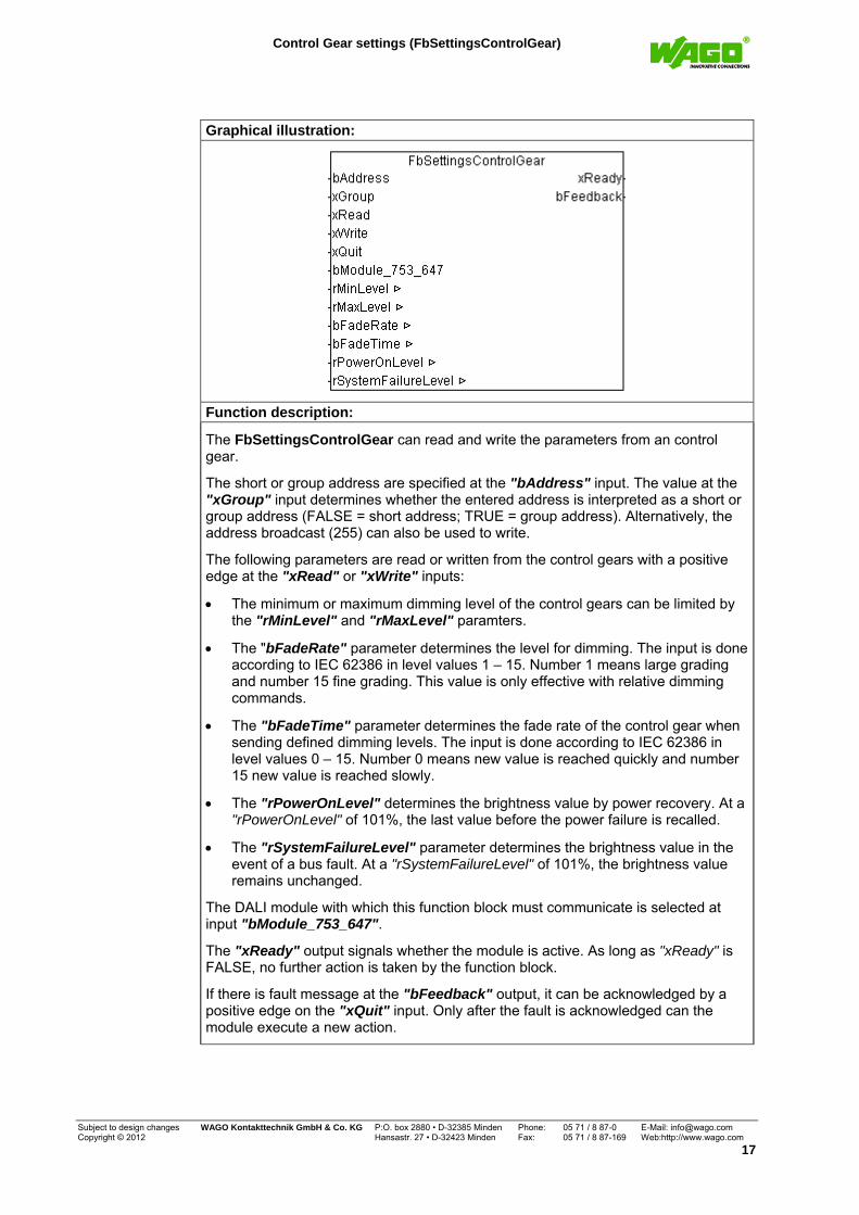
The FbSettingsControlGear can read and write the parameters from an control gear.
The short or group address are specified at the "bAddress" input. The value at the "xGroup" input determines whether the entered address is interpreted as a short or group address (FALSE = short address; TRUE = group address). Alternatively, the address broadcast (255) can also be used to write.
The following parameters are read or written from the control gears with a positive edge at the "xRead" or "xWrite" inputs:
The minimum or maximum dimming level of the control gears can be limited by the "rMinLevel" and "rMaxLevel" paramters.
The "bFadeRate" parameter determines the level for dimming. The input is done according to IEC 62386 in level values 1 – 15. Number 1 means large grading and number 15 fine grading. This value is only effective with relative dimming commands.
The "bFadeTime" parameter determines the fade rate of the control gear when sending defined dimming levels. The input is done according to IEC 62386 in level values 0 – 15. Number 0 means new value is reached quickly and number 15 new value is reached slowly.
The "rPowerOnLevel" determines the brightness value by power recovery. At a "rPowerOnLevel" of 101%, the last value before the power failure is recalled.
The "rSystemFailureLevel" parameter determines the brightness value in the event of a bus fault. At a "rSystemFailureLevel" of 101%, the brightness value remains unchanged.
The DALI module with which this function block must communicate is selected at input "bModule_753_647".
The "xReady" output signals whether the module is active. As long as "xReady" is FALSE, no further action is taken by the function block.
If there is fault message at the "bFeedback" output, it can be acknowledged by a positive edge on the "xQuit" input. Only after the fault is acknowledged can the module execute a new action.

Group Configuration (FbGroupConfig)
Subject to design changes WAGO Kontakttechnik GmbH & Co. KG P:O. box 2880 • D-32385 Minden Phone: 05 71 / 8 87-0 E-Mail: [email protected] Copyright © 2012 Hansastr. 27 • D-32423 Minden Fax.: 05 71 / 8 87-169 Web:http://www.wago.com
18
Group Configuration (FbGroupConfig)
WAGO-I/O-PRO Library Elements
Category: Building Automation
Name: FbGroupConfig
Type: Function Function block X Program
Name of library: WagoLibDALI_01.lib
Applicable to: See release note
Input parameter: Data type: Comment:
xRead BOOL A positive edge causes reading of the group configuration.
xWrite BOOL A positive edge writes the group configuration to the control gears.
bGroup BYTE Selection of the DALI group Range = 0 - 31
xGroupOn BOOL A positive edge switches the selected group on.
xGroupOff BOOL A positive edge switches the selected group off.
xFlash BOOL As long as the input is active, the selected group flashes.
xQuit BOOL A positive edge acknowledges the fault message on the "bFeedback" output.
bModule_753_647 BYTE Specifies which DALI master module is to be addressed at the controller. Counting is from left to right. Default setting = 1
Input/output parameter: Data type: Comment:
axGroupMember ARRAY [0..63] of BOOL
The array is used on the one hand to display the current group configuration. The array can be used on the other to redefine group members.
Return value: Data type: Comment:
xReady BOOL TRUE = communication deactivated FALSE = communication activated
bFeedback BYTE Response byte (see table 1 in the appendix)

Group Configuration (FbGroupConfig)
Subject to design changes WAGO Kontakttechnik GmbH & Co. KG P:O. box 2880 • D-32385 Minden Phone: 05 71 / 8 87-0 E-Mail: [email protected] Copyright © 2012 Hansastr. 27 • D-32423 Minden Fax: 05 71 / 8 87-169 Web:http://www.wago.com
19
Graphical illustration:
Function description:
The FbGroupConfig is used to configure the DALI groups. In addition to the 16 DALI groups, this function block can be used to define an additional 16 virtual groups.
With a positive edge at the "xRead" input, all control gears are queried if they belong to the "bGroup" group. Group members appear in the "axGroupMember" array.
With a positive edge at the "xWrite" input, all control gears that have been set to TRUE in the "axGroupMember" array are assigned to the "bGroup" group.
To check the group configuration, the group can be switched on or off by a positive edge at the "xGroupOn" or "xGroupOff" inputs.
As long as the "xFlash" input is active, the lights from the selected groups flash at a flash period set in the DALI module.
The DALI module with which this function block must communicate is selected at input "bModule_753_647".
The "xReady" output signals whether the module is active. As long as "xReady" is FALSE, no further action is taken by the function block.
If there is fault message at the "bFeedback" output, it can be acknowledged by a positive edge on the "xQuit" input. Only after the fault is acknowledged can the module execute a new action.
Note:
The virtual groups are saved to the DALI module and can have up to 8 members. All other subscribers are rejected.
For the virtual groups, the module sends the telegrams to all group members one after the other as fast as possible.

Scene Configuration (FbSceneConfig)
Subject to design changes WAGO Kontakttechnik GmbH & Co. KG P:O. box 2880 • D-32385 Minden Phone: 05 71 / 8 87-0 E-Mail: [email protected] Copyright © 2012 Hansastr. 27 • D-32423 Minden Fax.: 05 71 / 8 87-169 Web:http://www.wago.com
20
Scene Configuration (FbSceneConfig)
WAGO-I/O-PRO Library Elements
Category: Building Automation
Name: FbSceneConfig
Type: Function Function block X Program
Name of library: WagoLibDALI_01.lib
Applicable to: See release note
Input parameter: Data type: Comment:
xRead BOOL A positive edge causes reading of the scene configuration.
xWrite BOOL A positive edge writes the scene configuration to the control gears.
bScene BYTE Selection of the DALI scene Value range = 0 – 15
xQuit BOOL A positive edge acknowledges the fault message on the "bFeedback" output.
bModule_753_647 BYTE Specifies which DALI master module is to be addressed at the controller. Counting is from left to right. Default setting = 1
Input/output parameter: Data type: Comment:
arSceneValue ARRAY [0..63] of REAL
The array is used to display and configure the selected scene [%] Value range = 0 - 100% 101 = no scene value
Return value: Data type: Comment:
xReady BOOL TRUE = communication deactivated FALSE = communication activated
bFeedback BYTE Response byte (see table 1 in the appendix)
Graphical illustration:

Scene Configuration (FbSceneConfig)
Subject to design changes WAGO Kontakttechnik GmbH & Co. KG P:O. box 2880 • D-32385 Minden Phone: 05 71 / 8 87-0 E-Mail: [email protected] Copyright © 2012 Hansastr. 27 • D-32423 Minden Fax: 05 71 / 8 87-169 Web:http://www.wago.com
21
Function description:
The FbSceneConfig is used to configure the DALI scenes.
With a positive edge at the “xRead“ input or at a value change at the “bScene“ input, all ballasts are queried, which scene value they stored under the “bScene“ scene. The scene values are displayed in the “arSceneValue“ array.
With a positive edge at the "xWrite" input, the "bScene" scene is saved to all control gears with the scene value from the "arSceneValue" array.
The DALI module with which this function block must communicate is selected at input "bModule_753_647".
The "xReady" output signals whether the module is active. As long as "xReady" is FALSE, no further action is taken by the function block.
If there is fault message at the "bFeedback" output, it can be acknowledged by a positive edge on the "xQuit" input. Only after the fault is acknowledged can the module execute a new action.

Status Query of the Control Gears (FbStatusControlGear)
Subject to design changes WAGO Kontakttechnik GmbH & Co. KG P:O. box 2880 • D-32385 Minden Phone: 05 71 / 8 87-0 E-Mail: [email protected] Copyright © 2012 Hansastr. 27 • D-32423 Minden Fax.: 05 71 / 8 87-169 Web:http://www.wago.com
22
Status Query of the Control Gears (FbStatusControlGear)
WAGO-I/O-PRO Library Elements
Category: Building Automation
Name: FbStatusControlGear
Type: Function Function block X Program
Name of library: WagoLibDALI_01.lib
Applicable to: See release note
Input parameter: Data type: Comment:
xRead BOOL A positive edge causes reading of the status values from the internal module database.
xQuit BOOL A positive edge acknowledges the fault message on the "bFeedback" output.
bModule_753_647 BYTE Specifies which DALI master module is to be addressed at the controller. Counting is from left to right. Default setting = 1
Return value: Data type: Comment:
xReady BOOL TRUE = communication deactivated FALSE = communication activated
bFeedback BYTE Response byte (see table 1 in the appendix)
axShortAddress ARRAY [0..63] OF BOOL
Indication of the existing short addresses for control gears
axLampPowerOn ARRAY [0..63] OF BOOL
Indication of the lamps switched on
axStatusControlGear ARRAY [0..63] OF BOOL
Indication of the control gear faults
axLampFailure ARRAY [0..63] OF BOOL
Indication of the defective lamps
Graphical illustration:

Status Query of the Control Gears (FbStatusControlGear)
Subject to design changes WAGO Kontakttechnik GmbH & Co. KG P:O. box 2880 • D-32385 Minden Phone: 05 71 / 8 87-0 E-Mail: [email protected] Copyright © 2012 Hansastr. 27 • D-32423 Minden Fax: 05 71 / 8 87-169 Web:http://www.wago.com
23
Function description:
The FbStatusControlGear reads the current status of the control gears from the module database.
With a positive edge at the "xRead" input, the status of the control gears is read from the module database and displayed at the following outputs:
"axShortAddress" = Indication of the available control gears (online)
"axLampPowerOn" = Indication of which lamps are on
"axStatusControlGear" = Indication of which control gears have a fault
"axLampFailure"“ = Indication of which lamps are defective
The DALI module with which this function block must communicate is selected at input "bModule_753_647".
The "xReady" output signals whether the module is active. As long as "xReady" is FALSE, no further action is taken by the function block.
If there is fault message at the "bFeedback" output, it can be acknowledged by a positive edge on the "xQuit" input. Only after the fault is acknowledged can the module execute a new action.
Note:
The DALI module cyclically eads the status of the control gears. The WAGO-DALI-Configurator can be used to set the update rate.

Latching Relay (FbDaliLatchingRelay)
Subject to design changes WAGO Kontakttechnik GmbH & Co. KG P:O. box 2880 • D-32385 Minden Phone: 05 71 / 8 87-0 E-Mail: [email protected] Copyright © 2012 Hansastr. 27 • D-32423 Minden Fax.: 05 71 / 8 87-169 Web:http://www.wago.com
24
03 Switching
Latching Relay (FbDaliLatchingRelay)
WAGO-I/O-PRO Library Elements
Category: Building Automation
Name: FbDaliLatchingRelay
Type: Function Function block X Program
Name of library: WagoLibDALI_01.lib
Applicable to: See release note
Input parameter: Data type: Comment:
bAddress BYTE Short address of 0 – 63 Group address 0 - 31 Broadcast = 255
xGroup BOOL Selects short or group address: FALSE = short address or broadcast TRUE = group address Default setting = FALSE
xButton BOOL Input from switch lighting request
rDimmLevelForOff REAL dimming level which switching off [%] Default setting = 0% (off)
bModule_753_647 BYTE Specifies which DALI master module is to be addressed at the controller. Counting is from left to right. Default setting = 1
Return value: Data type: Comment:
xReady BOOL TRUE = communication deactivated FALSE = communication activated
bFeedback BYTE Response byte (see table 1 in the appendix)
rActualLevel REAL Indication of the current dimming level [%]
Graphical illustration:

Latching Relay (FbDaliLatchingRelay)
Subject to design changes WAGO Kontakttechnik GmbH & Co. KG P:O. box 2880 • D-32385 Minden Phone: 05 71 / 8 87-0 E-Mail: [email protected] Copyright © 2012 Hansastr. 27 • D-32423 Minden Fax: 05 71 / 8 87-169 Web:http://www.wago.com
25
Function description:
The FbDaliLatchingRelay forms the function of an latching relay.
The short or group address are specified at the "bAddress" input. The value at the "xGroup" input determines whether the entered address is interpreted as a short or group address (FALSE = short address; TRUE = group address).
A rising edge at the "xButton" input causes the light addressed by the short or group address to switch on or off. Whether the light is switched on or off depends on the previous switching state of the lighting.
If "rDimmLevelForOff" is greater than zero, the lights are not switched off, rather set to the dimming level set at the "rDimmLevelForOff" input.
The DALI module with which this function block must communicate is selected at input "bModule_753_647".
The "xReady" output signals whether the module is active. As long as "xReady" is FALSE, no further action is taken by the function block.
The output “bFeedback” outputs a numeric code with the response. Numeric codes are listed in Table 1 in the Appendix.
The "rActualLevel" output displays the current dimming level of the selected short address or group.

ON/OFF Switch (FbDaliSwitchOnOff)
Subject to design changes WAGO Kontakttechnik GmbH & Co. KG P:O. box 2880 • D-32385 Minden Phone: 05 71 / 8 87-0 E-Mail: [email protected] Copyright © 2012 Hansastr. 27 • D-32423 Minden Fax.: 05 71 / 8 87-169 Web:http://www.wago.com
26
ON/OFF Switch (FbDaliSwitchOnOff)
WAGO-I/O-PRO Library Elements
Category: Building Automation
Name: FbDaliSwitchOnOff
Type: Function Function block X Program
Name of library: WagoLibDALI_01.lib
Applicable to: See release note
Input parameter: Data type: Comment:
bAddress BYTE Short address of 0 – 63 Group address 0 - 31 Broadcast = 255
xGroup BOOL Selects short or group address: FALSE = short address or broadcast TRUE = group address Default setting = FALSE
xOn BOOL A positive edge switches the selected control gears on.
xOff BOOL A positive edge switches the selected control gears off.
rDimmLevelForOff REAL dimming level which switching off [%] Default setting = 0% (off)
bModule_753_647 BYTE Specifies which DALI master module is to be addressed at the controller. Counting is from left to right. Default setting = 1
Return value: Data type: Comment:
xReady BOOL TRUE = communication deactivated FALSE = communication activated
bFeedback BYTE Response byte (see table 1 in the appendix)
rActualLevel REAL Indication of the current dimming level [%]
Graphical illustration:

ON/OFF Switch (FbDaliSwitchOnOff)
Subject to design changes WAGO Kontakttechnik GmbH & Co. KG P:O. box 2880 • D-32385 Minden Phone: 05 71 / 8 87-0 E-Mail: [email protected] Copyright © 2012 Hansastr. 27 • D-32423 Minden Fax: 05 71 / 8 87-169 Web:http://www.wago.com
27
Function description:
The FbDaliSwitchOnOff forms the function of a switch.
The short or group address are specified at the "bAddress" input. The value at the "xGroup" input determines whether the entered address is interpreted as a short or group address (FALSE = short address; TRUE = group address).
A rising edge at the "xOn" or "xOff" inputs causes the light addressed by the short or group address to switch on or off.
If "rDimmLevelForOff" is greater than zero, the lights are not switched off, rather set to the dimming level set at the "rDimmLevelForOff" input.
The DALI module with which this function block must communicate is selected at input "bModule_753_647".
The "xReady" output signals whether the module is active. As long as "xReady" is FALSE, no further action is taken by the function block.
The output “bFeedback” outputs a numeric code with the response. Numeric codes are listed in Table 1 in the Appendix.
The "rActualLevel" output displays the current dimming level of the selected short address or group.

Dimmer Double Button (FbDaliDimmDoubleButton)
Subject to design changes WAGO Kontakttechnik GmbH & Co. KG P:O. box 2880 • D-32385 Minden Phone: 05 71 / 8 87-0 E-Mail: [email protected] Copyright © 2012 Hansastr. 27 • D-32423 Minden Fax.: 05 71 / 8 87-169 Web:http://www.wago.com
28
04 Dimming
Dimmer Double Button (FbDaliDimmDoubleButton)
WAGO-I/O-PRO Library Elements
Category: Building Automation
Name: FbDaliDimmDoubleButton
Type: Function Function block X Program
Name of library: WagoLibDALI_01.lib
Applicable to: See release note
Input parameter: Data type: Comment:
bAddress BYTE Short address of 0 – 63 Group address 0 - 31 Broadcast = 255
xGroup BOOL Selects short or group address: FALSE = short address or broadcast TRUE = group address Default setting = FALSE
xOnAndStepUp BOOL Button signal for power on and step up brightness
xOffAndStepDown BOOL Button signal for power off and step down brightness
typConfigDimmer typConfig Dimmer
Setting parameter for the dimmer
.tShortPushButton TIME Maximum time for a brief button press Default = t#500ms
.xOnlyDimming BOOL Only the "xOnAndStepUp" and "xOffAndStepDown" inputs can be used to dim.
.xSwitchOnLastLevel BOOL Switching on with the last dimming level
.xUseSwitchOnLevel BOOL switching on with a defined dimming level
.bSwitchOnLevel BYTE dimming level when switching on [%] Value range 0 – 100 [%] Default setting = 90
.xMinLevelAsOff BOOL Instead of the switch-off command, the lighting is dimmed to the min. level. Default setting = FALSE
.xSwitchOnAndStepUp BOOL Before dimming, a switch-on command is sent.
.xStepDownAnd SwitchOff
BOOL If the minimum dimming level is reached, the lighting is switched off.
bModule_753_647 BYTE Specifies which DALI master module is to be addressed at the controller. Counting is from left to right. Default setting = 1

Dimmer Double Button (FbDaliDimmDoubleButton)
Subject to design changes WAGO Kontakttechnik GmbH & Co. KG P:O. box 2880 • D-32385 Minden Phone: 05 71 / 8 87-0 E-Mail: [email protected] Copyright © 2012 Hansastr. 27 • D-32423 Minden Fax: 05 71 / 8 87-169 Web:http://www.wago.com
29
Return value: Data type: Comment:
xReady BOOL TRUE = communication deactivated FALSE = communication activated
bFeedback BYTE Response byte (see table 1 in the appendix)
rActualLevel REAL Indication of the current dimming level [%]
Graphical illustration:
Function description:
The FbDaliDimmDoubleButton module can be used to dim the DALI lighting. The lighting is dimmed or powered on and off by controlling two separate button inputs.
The short or group address are specified at the "bAddress" input. The value at the "xGroup" input determines whether the entered address is interpreted as a short or group address (FALSE = short address; TRUE = group address).
The lighting is switched by a brief button press at the "xButton" input. At which dimming level the lighting is switched on depends on the following options:
"typConfigDimmer.xSwitchOnLastLevel" = Switched on at the last dimming level
"typConfigDimmer.xUseSwitchOnLevel" = Switched on at the defined dimming level "typConfigDimmer.bSwitchOnLevel"
If neither of the two options is selected, the lighting is switched on at the maximum dimming level.
The lighting is switched off by a brief button press at the "xOffAndStepDown" input. If the "typConfigDimmer.xMinLevelAsOff" parameter is activated, the minimum dimming level is called up instead of the switch-off command.
If the "typConfigDimmer.xOnlyDimming" parameter is activated, the functions of the "brief button press" are not supported.
The lighting is turned brighter by a long button press at the "xOnAndStepUp" input. If the "typConfigDimmer.xSwitchOnAndStepUp" options is activated, a switch-on command is sent before dimming.
The lighting is turned darker by a long button press at the "xOffAndStepDown" input. If the "typConfigDimmer.xStepDownAndSwitchOff" option is activated, the lighting is switched off at the minimum dimming level.
The time for differentiating between a short and long button press can be specified via the "tShortPushButton" input parameter. Any button pulse that is smaller in value than the set parameter value is interpreted as a short button press.

Dimmer Double Button (FbDaliDimmDoubleButton)
Subject to design changes WAGO Kontakttechnik GmbH & Co. KG P:O. box 2880 • D-32385 Minden Phone: 05 71 / 8 87-0 E-Mail: [email protected] Copyright © 2012 Hansastr. 27 • D-32423 Minden Fax.: 05 71 / 8 87-169 Web:http://www.wago.com
30
The DALI module with which this function block must communicate is selected at input "bModule_753_647".
The "xReady" output signals whether the module is active. As long as "xReady" is FALSE, no further action is taken by the function block.
The output “bFeedback” outputs a numeric code with the response. Numeric codes are listed in Table 1 in the Appendix.
The "rActualLevel" output displays the current dimming level of the selected short address or group.

Dimmer Single Button (FbDaliDimmSingleButton)
Subject to design changes WAGO Kontakttechnik GmbH & Co. KG P:O. box 2880 • D-32385 Minden Phone: 05 71 / 8 87-0 E-Mail: [email protected] Copyright © 2012 Hansastr. 27 • D-32423 Minden Fax: 05 71 / 8 87-169 Web:http://www.wago.com
31
Dimmer Single Button (FbDaliDimmSingleButton)
WAGO-I/O-PRO Library Elements
Category: Building Automation
Name: FbDaliDimmSingleButton
Type: Function Function block X Program
Name of library: WagoLibDALI_01.lib
Applicable to: See release note
Input parameter: Data type: Comment:
bAddress BYTE Short address of 0 – 63 Group address 0 - 31 Broadcast = 255
xGroup BOOL Selects short or group address: FALSE = short address or broadcast TRUE = group address Default setting = FALSE
xButton BOOL Short button press = ON/OFF Long button press = brighter/darker
typConfigDimmer typConfig Dimmer
Setting parameter for the dimmer
.tShortPushButton TIME Maximum time for a brief button press Default = t#500ms
.xOnlyDimming BOOL Only the "xOnAndStepUp" and "xOffAndStepDown" inputs can be used to dim.
.xSwitchOnLastLevel BOOL Switching on with the last dimming level
.xUseSwitchOnLevel BOOL switching on with a defined dimming level
.bSwitchOnLevel BYTE dimming level when switching on [%] Value range 0 – 100 [%] Default setting = 90
.xMinLevelAsOff BOOL Instead of the switch-off command, the lighting is dimmed to the min. level. Default setting = FALSE
.xSwitchOnAndStepUp BOOL Before dimming, a switch-on command is sent.
.xStepDownAnd SwitchOff
BOOL If the minimum dimming level is reached, the lighting is switched off.
bModule_753_647 BYTE Specifies which DALI master module is to be addressed at the controller. Counting is from left to right. Default setting = 1
Return value: Data type: Comment:
xReady BOOL TRUE = communication deactivated FALSE = communication activated
bFeedback BYTE Response byte (see table 1 in the appendix)
rActualLevel REAL Indication of the current dimming level [%]

Dimmer Single Button (FbDaliDimmSingleButton)
Subject to design changes WAGO Kontakttechnik GmbH & Co. KG P:O. box 2880 • D-32385 Minden Phone: 05 71 / 8 87-0 E-Mail: [email protected] Copyright © 2012 Hansastr. 27 • D-32423 Minden Fax.: 05 71 / 8 87-169 Web:http://www.wago.com
32
Graphical illustration:
Function description:
The FbDaliDimmSingleButton module can be used to dim the DALI lighting. The lighting is dimmed or powered on and off by controlling one button.
The short or group address to which the DALI commands are to be sent is specified at the input "bAddress". The value at input "xGroup" determines whether the entered address is interpreted by the function block as a short or group address (FALSE = short address; TRUE = group address).
The lighting is switched on when off by briefly pressing the button at the "xButton" input. At which dimming level the lighting is switched on depends on the following options:
"typConfigDimmer.xSwitchOnLastLevel" = Switched on at the last dimming level
"typConfigDimmer.xUseSwitchOnLevel" = Switched on at the defined dimming level "typConfigDimmer.bSwitchOnLevel"
If neither of the two options is selected, the lighting is switched on at the maximum dimming level.
The lighting is switched off when on by a brief button press at the "xButton" input. If the "typConfigDimmer.xMinLevelAsOff" parameter is activated, the minimum dimming level is called up instead of the switch-off command.
If the "typConfigDimmer.xOnlyDimming" parameter is activated, the functions of the "brief button press" are not supported.
The lighting is turned brighter by a long button press at the "xButton" input. If the "typConfigDimmer.xSwitchOnAndStepUp" options is activated, a switch-on command is sent before dimming.
The lighting is turned darker by the next long button press at the "xButton" input. If the "typConfigDimmer.xStepDownAndSwitchOff" option is activated, the lighting is switched off at the minimum dimming level.
The lighting is turned brighter by the next long button press at the "xButton" input., etc.
The time for differentiating between a short and long button press can be specified via the "tShortPushButton" input parameter. Any button pulse that is smaller in value than the set parameter value is interpreted as a short button press.
The DALI module with which this function block must communicate is selected at input "bModule_753_647".

Dimmer Single Button (FbDaliDimmSingleButton)
Subject to design changes WAGO Kontakttechnik GmbH & Co. KG P:O. box 2880 • D-32385 Minden Phone: 05 71 / 8 87-0 E-Mail: [email protected] Copyright © 2012 Hansastr. 27 • D-32423 Minden Fax: 05 71 / 8 87-169 Web:http://www.wago.com
33
The "xReady" output signals whether the module is active. As long as "xReady" is FALSE, no further action is taken by the function block.
The output “bFeedback” outputs a numeric code with the response. Numeric codes are listed in Table 1 in the Appendix.
The "rActualLevel" output displays the current dimming level of the selected short address or group.

Constant Light Control (FbDaliConstantLightControl)
Subject to design changes WAGO Kontakttechnik GmbH & Co. KG P:O. box 2880 • D-32385 Minden Phone: 05 71 / 8 87-0 E-Mail: [email protected] Copyright © 2012 Hansastr. 27 • D-32423 Minden Fax.: 05 71 / 8 87-169 Web:http://www.wago.com
34
05 Light Control
Constant Light Control (FbDaliConstantLightControl)
WAGO-I/O-PRO Library Elements
Category: Building Automation
Name: FbDaliConstantLightControl
Type: Function Function block X Program
Name of library: WagoLibDALI_01.lib
Applicable to: See release note
Input parameter: Data type: Comment:
bAddress BYTE Short address of 0 – 63 Group address 0 - 31 Broadcast = 255
xGroup BOOL Selects short or group address: FALSE = short address or broadcast TRUE = group address Default setting = FALSE
xControlOff BOOL The control is switched off
xOn BOOL The lighting is switched on
xOff BOOL The lighting is switched off
xToggle BOOL A positive edge at the input switches the lighting on or off.
xOnAndStepUp BOOL The lighting is switched on by pushing the button briefly, the lighting is dimmed brighter by pushing the button longer. (if "xSetpValueShifting" = TRUE)
xOffAndStepDown BOOL The lighting is switched off by pushing the button briefly, the lighting is dimmed lower by pushing the button longer. (if "xSetpValueShifting" = TRUE)
rMeasuredLightLevel REAL Input signal of the light sensor [lx]
xPresenceDetector BOOL Switching signal of the presence detector. The lighting and controller are switched off by a falling edge.
typConfigFbDaliConstant LightControl
typConfig Dali Constant Light Control
Setting parameter for the constant light control
.tOffDelayAtMinLevel TIME Switch-off delay of the lighting at minimum dimming level Default setting = t#15m (t#0s = no swich-off)
.tOffDelayStandby TIME Swtich-off delay of the lighting in standby mode Default setting = t#30m (t#0s = no standby mode)

Constant Light Control (FbDaliConstantLightControl)
Subject to design changes WAGO Kontakttechnik GmbH & Co. KG P:O. box 2880 • D-32385 Minden Phone: 05 71 / 8 87-0 E-Mail: [email protected] Copyright © 2012 Hansastr. 27 • D-32423 Minden Fax: 05 71 / 8 87-169 Web:http://www.wago.com
35
.bFadeTimeOn BYTE Fade time, when the light is turned on
Default setting = 4
.bFadeTimeStandby BYTE Fade time, when the controller goes into stand-by mode Default setting = 9
.bFadeTimeOff BYTE Fade time, when the light is switched off Default setting = 7
.rPresetReferenceLight Level
REAL Setpoint value when switching on [lx] Default setting = 500 lx
.rGain REAL Gain of the light sensor measured value Default setting = 3
.rGainAdaption REAL Adaptation of the gain depending on the daylight percentage [%] Value range: 0 - 90 % Default setting = 20
.rSwitchOnDimmLevel REAL Dimming level when switching on before the controller is activated [%] Default setting = 50 %
.rStandbyLevel REAL Dimming level in standby mode [%] Default setting = 3 %
.rSetpValueShifting REAL The "rReferenceLightLevel" setpoint value can be moved up or down using the "xOnAndStepUp" and "xOffAndStepDown" buttons. Default setting = TRUE
.xRememberLastLight Level
BOOL The lighting is adjusted to the "rReferenceLightLevel" after switching on. Otherwise, it is adjusted to the "rPresetReferenceLightLevel" setpoint value. Default setting = FALSE
.xEnableSwitchOnAt Presence
BOOL The presence detector automatically switches the lighting on. Requirement: actual value < setpoint valueDefault setting = TRUE
.xDimmingActivate Controller
BOOL A long button press at the "xOnAndStepUp" and "xOffAndStepDown" inputs activates the controller. Default setting = TRUE
.xDisableShortPress BOOL The brief button press is deactivated at both "xOnAndStepUp" and "xOffAndStepDown" button inputs. Default setting = FALSE
bModule_753_647 BYTE Specifies which DALI master module is to be addressed at the controller. Counting is from left to right. Default setting = 1
Input/output parameter: Data type: Comment:
rReferenceLightLevel REAL Setpoint value for light intensity in [lx]

Constant Light Control (FbDaliConstantLightControl)
Subject to design changes WAGO Kontakttechnik GmbH & Co. KG P:O. box 2880 • D-32385 Minden Phone: 05 71 / 8 87-0 E-Mail: [email protected] Copyright © 2012 Hansastr. 27 • D-32423 Minden Fax.: 05 71 / 8 87-169 Web:http://www.wago.com
36
Feedback value: Data type: Comment: xReady BOOL TRUE = communication deactivated
FALSE = communication activated
bFeedback BYTE Response byte (see table 1 in the appendix)
rActualLevel REAL Indication of the current dimming level [%]
Graphical illustration:
Function description:
The function block enables constant light to be controlled automatically in connection with a light sensor.
The short or group address to which the DALI commands are to be sent is specified at the input "bAddress". The value at input "xGroup" determines whether the entered address is interpreted by the function block as a short or group address (FALSE = short address; TRUE = group address).
The DALI master module with which this function block must communicate is selected at input "bModule_753_647".
The control can be deactivated via input "xControlOff" so that, for example, when selecting a scene of the relevant address, the dimming level will not be immediately overwritten.
Before the controller is activated, the lighting is generally switched on at the "typConfigFbDaliConstantLightControl.rSwitchOnDimmLevel" dimming level.
The transition time when switching on the lighting is determined by parameter "typConfigFbDaliConstantLightControl.bFadeTimeOn“.
A positive edge at the "xOn" and "xOff" inputs switches the lighting and controller on or off.
A positive edge at the "xToggle" input switches the lighting and controller on or off depending on state.
The "rReferenceLightLevel" setpoint value for light intensity can be moved up or down with a long button press at the "xOnAndStepUp" and "xOffAndStepDown". The setpoint offset must be activated with the "typConfigFbDaliConstantLightControl.xSetpValueShifting" parameter.

Constant Light Control (FbDaliConstantLightControl)
Subject to design changes WAGO Kontakttechnik GmbH & Co. KG P:O. box 2880 • D-32385 Minden Phone: 05 71 / 8 87-0 E-Mail: [email protected] Copyright © 2012 Hansastr. 27 • D-32423 Minden Fax: 05 71 / 8 87-169 Web:http://www.wago.com
37
Alternatively, the "xOnAndStepUp" and "xOffAndStepDown" inputs can be used as simple dimmers if "typConfigFbDaliConstantLightControl .xDimmingActivateController" is deactivated.
A brief button press at the "xOnAndStepUp" or "xOffAndStepDown" inputs switches the lighting on or off. Evaluation of the brief button press by the "typConfigFbDaliConstantLightControl .xDisableShortPress" parameter cannot be switched off. When switching on the lighting, the light intensity is adjusted to the "rReferenceLightLevel".
The "typConfigFbDaliConstantLightControl.tSwitchOffDelay" input specifies the time after which the lighting changes to standby mode at the minimum dimming level. Any change to the dimming level restarts the switch-off delay. The t#0s value can be used to deactivate switching off the lighting at minimum dimming level.
In standby mode, the lighting is dimmed to the "typConfigFbDaliConstantLightControl.rStandbyLevel" level.
The "typConfigFbDaliConstantLightControl.tOffDelayStandby" input specifies the runtime of the standby mode. After the time has expired, the lighting is switched off. The t#0s value can be used to deactivate the standby function.
The transition time when switching the lighting off is determined by parameter "typConfigFbDaliConstantLightControl.bFadeTimeOff“.
If "typConfigFbDaliConstantLightControl.xRememberLastLightLevel" is activated, the lighting is adjusted to the last setpoint value "rReferenceLightLevel" when it is switched on. If the parameter is not activated, the lighting is adjusted to the setpoint value "typConfigFbDaliConstantLightControl .rPresetReferenceLightLevel" when switched on.
The "rMeasuredLightLevel" input passes the actual value from the light sensor to the module.
With a presence dependent constant light control, the switching contact of the presence detector is connected to the input "xPresenceDetector". The lighting is switched off or set to standby mode by a falling edge of the presence detector.
If "typConfigFbDaliConstantLightControl.xEnableSwitchOnAtPresence" is activated, the "xPresenceDetector" input can also switch on the lighting. This can only be done when the actual value is smaller than the setpoint value by 50 lx.
The "typConfigFbDaliConstantLightControl.rGain" and "typConfigFbDaliConstantLightControl.rGainAdaption" parameters are used to compare the measured value of the light sensor on the ceiling with the light intensity at the workplace.
The "xReady" output signals whether the module is active. As long as "xReady" is FALSE, no further action is taken by the function block.
The output “bFeedback” outputs a numeric code with the response. Numeric codes are listed in Table 1 in the Appendix.
The "rActualLevel" output displays the current dimming level of the selected short address or group.
Note:
The "rReferenceLightLevel" variable should be defined as RETAIN.

Constant Light Control (FbDaliConstantLightControl)
Subject to design changes WAGO Kontakttechnik GmbH & Co. KG P:O. box 2880 • D-32385 Minden Phone: 05 71 / 8 87-0 E-Mail: [email protected] Copyright © 2012 Hansastr. 27 • D-32423 Minden Fax.: 05 71 / 8 87-169 Web:http://www.wago.com
38
Time Referenced Behavior:
Controller
3
2
4
5
1
7
68
1 Initial dimm level (".rSwitchOnDimmLevel“)
2 Transition time when switching on (".bFadeTimeOn“)
3 ON delay controller (".tDaliOnDelayController“)
4 Presence + run time, light control is active, transition time = 0
5 Transition time when switching to stand-by mode(".bFadeTimeStandby“)
6 Dimming value in standby mode (".rStandbyLevel“)
7 Max. run time in standby mode (".tOffDelayStandby“)
8 Transition time when switching off (".bFadeTimeOff“)
Dimm value [%]
Time [s]

Constant Light Control (FbDaliConstantLightControl)
Subject to design changes WAGO Kontakttechnik GmbH & Co. KG P:O. box 2880 • D-32385 Minden Phone: 05 71 / 8 87-0 E-Mail: [email protected] Copyright © 2012 Hansastr. 27 • D-32423 Minden Fax: 05 71 / 8 87-169 Web:http://www.wago.com
39
Calibration requirements:
The source of light to be measured must be switched on about 20 minutes before measuring, so that the lamps can operate at their full potential.
The setpoint value for light intensity is to be measured on the work surface. A luxmeter is required that has a good adaptation to the V(λ) curve.
The calibration cannot be performed until the room has been completely furnished since the measured values of the light sensor depend on the reflection properties of the room.
Start value "rGain" = 3
Start value "rGainAdaption" = 20
Two measurements are required for calibrating the light sensor. For both measurements, the luxmeter is placed on the work surface where the desired light intensity must be reached.
The first measurement is performed in a darkened room using pure artificial light. The calibration value is determined as follows:
If the light intensity in the workplace is higher than the setpoint light intensity, the calibration value must be increased until the desired light intensity is reached.
If the light intensity in the workplace is lower than the setpoint light intensity, the calibration value must be decreased until the desired light intensity is reached.
For safety reasons, the light intensity measured by the luxmeter should be about 10 % higher than the desired setpoint light intensity.
The second calibration measurement is required in order to determine the percentage adaptation of the calibration value. This measurement is performed in a semi-darkened room with residual artificial light.
The second measurement is performed as follows:
If the light intensity in the workplace is lower than the setpoint light intensity, the percentage of the adaptation must be increased until the desired light intensity is reached.
If the light intensity in the workplace is higher than the desired light intensity, the percentage of the adaptation must be decreased until the desired light intensity is reached.
If the percentage adaptation of the calibration value is performed in a semi-darkened room, the lowest possible offset is achieved depending on the part of daylight or artificial light. The actual value of the light intensity can still be lower than the setpoint light intensity.

Constant Light Control (FbDaliConstantLightControl)
Subject to design changes WAGO Kontakttechnik GmbH & Co. KG P:O. box 2880 • D-32385 Minden Phone: 05 71 / 8 87-0 E-Mail: [email protected] Copyright © 2012 Hansastr. 27 • D-32423 Minden Fax.: 05 71 / 8 87-169 Web:http://www.wago.com
40
Calibration:
Luminous intensity: 100% artificial light
“rGain” =5 “rGainAdaption” = 50
Luminous intensity: 50% artificial light
50% daylight
Calibration completed
Decrease “rGain” Increase “rGain”
actual <
setpoint
actual < setpoint
actual = setpoint
actual =
setpoint
Increase “rGainAdaption”
Decrease “rGainAdaption”
No No
No No
Yes
Yes Yes
Yes

Constant Light Control Settings (FbDaliConfigConstantLightControl)
Subject to design changes WAGO Kontakttechnik GmbH & Co. KG P:O. box 2880 • D-32385 Minden Phone: 05 71 / 8 87-0 E-Mail: [email protected] Copyright © 2012 Hansastr. 27 • D-32423 Minden Fax: 05 71 / 8 87-169 Web:http://www.wago.com
41
Constant Light Control Settings (FbDaliConfigConstantLightControl)
WAGO-I/O-PRO Library Elements
Category: Building Automation
Name: FbDaliConfigConstantLightControl
Type: Function Function block X Program
Name of library: WagoLibDALI_01.lib
Applicable to: See release note
Input parameter: Data type: Comment:
tDelayAutoSwitchOn TIME Switch-on delay when switching on the lighting if the setpoint value falls short by 50 lx and presence is detected. Default setting = t#30s
rKp REAL Constant light control gain Default setting = 0.005
rTnGreaterVariance REAL Reset time for large setpoint/actual value deviation [s] Default setting = 500
rTnSmallVariance REAL Reset time for small setpoint/actual value deviation [s] Default setting = 800
tOnDelayController TIME Switch-on delay of the controller after the lighting has been switched on. Default setting = t#5s
tShortPushButton TIME Maximum time for a brief button press Default = t#500ms
Graphical illustration:
Function description:
The FbDaliConfigConstantLightControl can be used to change any global setting for all DALI constant light controls in the project.

Scene Recall (FbDaliRecallScene)
Subject to design changes WAGO Kontakttechnik GmbH & Co. KG P:O. box 2880 • D-32385 Minden Phone: 05 71 / 8 87-0 E-Mail: [email protected] Copyright © 2012 Hansastr. 27 • D-32423 Minden Fax.: 05 71 / 8 87-169 Web:http://www.wago.com
42
06 Scenes
Scene Recall (FbDaliRecallScene)
WAGO-I/O-PRO Library Elements
Category: Building Automation
Name: FbDaliRecallScene
Type: Function Function block X Program
Name of library: WagoLibDALI_01.lib
Applicable to: See release note
Input parameter: Data type: Comment:
bAddress BYTE Short address of 0 – 63 Group address 0 - 31 Broadcast = 255
xGroup BOOL Selects short or group address: FALSE = short address or broadcast TRUE = group address Default setting = FALSE
xScene0 BOOL A positive edge calls up scene 0
xScene1 BOOL A positive edge calls up scene 1
… …
xScene14 BOOL A positive edge calls up scene 14
xScene15 BOOL A positive edge calls up scene 15
bScene BYTE Scene recall when the scene number changes Value range = 0 - 15
xUpdateScene BOOL The scene selected at the "bScene" input is called by positive edge
bModule_753_647 BYTE Specifies which DALI master module is to be addressed at the controller. Counting is from left to right. Default setting = 1
Return value: Data type: Comment:
xReady BOOL TRUE = communication deactivated FALSE = communication activated
bFeedback BYTE Response byte (see table 1 in the appendix)

Scene Recall (FbDaliRecallScene)
Subject to design changes WAGO Kontakttechnik GmbH & Co. KG P:O. box 2880 • D-32385 Minden Phone: 05 71 / 8 87-0 E-Mail: [email protected] Copyright © 2012 Hansastr. 27 • D-32423 Minden Fax: 05 71 / 8 87-169 Web:http://www.wago.com
43
Graphical illustration:
Function description:
The FbDaliRecallScene can be used to call up the DALI light scenes defined in the control gear.
At the "bAddress" input, the short and group address is assigned to which the DALI command should be sent. The value at input "xGroup" determines whether the entered address is interpreted by the function block as a short or group address (FALSE = short address; TRUE = group address).
The DALI light scenes can be called in two different ways.
1.) With a positive edge at inputs "xScene0" to "xScene15", the corresponding DALI light scene is called.
2.) If a value changes at the "bScene" input or with a positive edge at the "xUpdateScene" input, the DALI light scene specified at the "bScene" input is called up.
The DALI module with which this function block must communicate is selected at input "bModule_753_647".
The "xReady" output signals whether the module is active. As long as "xReady" is FALSE, no further action is taken by the function block.
The output “bFeedback” outputs a numeric code with the response. Numeric codes are listed in Table 1 in the Appendix.

Subject to design changes WAGO Kontakttechnik GmbH & Co. KG P:O. box 2880 • D-32385 Minden Phone: 05 71 / 8 87-0 E-Mail: [email protected] Copyright © 2012 Hansastr. 27 • D-32423 Minden Fax.: 05 71 / 8 87-169 Web:http://www.wago.com
44
07 General
Send Direct Dim Level (FbDaliSendDimmValue)
WAGO-I/O-PRO Library Elements
Category: Building Automation
Name: FbDaliSendDimmValue
Type: Function Function block X Program
Name of library: WagoLibDALI_01.lib
Applicable to: See release note
Input parameter: Data type: Comment:
bAddress BYTE Short address of 0 – 63 Group address 0 - 31 Broadcast = 255
xGroup BOOL Selects short or group address: FALSE = short address or broadcast TRUE = group address Default setting = FALSE
rDimmValue REAL The dimming level specified at the input is sent after each change in value [%]. Value range = 0 – 100 %
rHysteresis REAL Hysteresis [%] Value range = 1 % - 100 % Default setting = 1 %
xUpdate BOOL A positive edge sends the "rDimmValue" dimming level again.
bModule_753_647 BYTE Specifies which DALI master module is to be addressed at the controller. Counting is from left to right. Default setting = 1
Return value: Data type: Comment:
xReady BOOL TRUE = communication deactivated FALSE = communication activated
bFeedback BYTE Response byte (see table 1 in the appendix)

Subject to design changes WAGO Kontakttechnik GmbH & Co. KG P:O. box 2880 • D-32385 Minden Phone: 05 71 / 8 87-0 E-Mail: [email protected] Copyright © 2012 Hansastr. 27 • D-32423 Minden Fax: 05 71 / 8 87-169 Web:http://www.wago.com
45
Graphical illustration:
Function description:
The FbDaliSendDimmValue sends direct dimming levels to the selected DALI control gears.
At the "bAddress" input, the short and group address is assigned to which the DALI command should be sent. The value at input "xGroup" determines whether the entered address is interpreted by the function block as a short or group address (FALSE = short address; TRUE = group address).
If the value change at the “rDimmValue“ input is greater than “rHysteresis“ or a positive edge is detected at the “xUpdate“ input, the selected lamps are dimmed to the dimming value set at the “rDimmValue“ input.
The DALI module with which this function block must communicate is selected at input "bModule_753_647".
The "xReady" output signals whether the module is active. As long as "xReady" is FALSE, no further action is taken by the function block.
The output “bFeedback” outputs a numeric code with the response. Numeric codes are listed in Table 1 in the Appendix.

Send individual DALI commands (FbDaliControlGearCommands)
Subject to design changes WAGO Kontakttechnik GmbH & Co. KG P:O. box 2880 • D-32385 Minden Phone: 05 71 / 8 87-0 E-Mail: [email protected] Copyright © 2012 Hansastr. 27 • D-32423 Minden Fax.: 05 71 / 8 87-169 Web:http://www.wago.com
46
Send individual DALI commands (FbDaliControlGearCommands)
WAGO-I/O-PRO Library Elements
Category: Building Automation
Name: FbDaliControlGearCommands
Type: Function Function block X Program
Name of library: WagoLibDALI_01.lib
Applicable to: See release note
Input parameter: Data type: Comment:
bAddress BYTE Short address of 0 – 63 Group address 0 - 31 Broadcast = 255
xGroup BOOL Selects short or group address: FALSE = short address or broadcast TRUE = group address Default setting = FALSE
xDirectArcPowerControl BOOL TRUE = Direct dimming value (raw value) FALSE = DALI command
wCommand WORD Command (see table 2 in the appendix)
bSpecialValue BYTE Special values (see table 2 in the appendix)
bModule_753_647 BYTE Specifies which DALI master module is to be addressed at the controller. Counting is from left to right. Default setting = 1
Input/output parameter: Data type: Comment:
xSend BOOL If the input is set, the DALI command is transmitted to the terminal. After transfer, the input is reset by the function module.
Return value: Data type: Comment:
xReady BOOL TRUE = communication deactivated FALSE = communication activated
bFeedback BYTE Response byte (see table 1 in the appendix)
bValue BYTE Feedback from the ECG (raw value)

Subject to design changes WAGO Kontakttechnik GmbH & Co. KG P:O. box 2880 • D-32385 Minden Phone: 05 71 / 8 87-0 E-Mail: [email protected] Copyright © 2012 Hansastr. 27 • D-32423 Minden Fax: 05 71 / 8 87-169 Web:http://www.wago.com
47
Graphical illustration:
Function description:
With the FbDaliControlGearCommands module, it is possible to issue the DALI commands specified in standard IEC 82386 (see Table 2 in the appendix).
The short or group address to which the DALI commands are to be sent is specified at the input "bAddress". The value at input "xGroup" determines whether the entered address is interpreted by the function block as a short or group address (FALSE = short address; TRUE = group address).
Address 16#FF (255) can be entered at input „bAddress“ for the broadcasting commands.
When input "xDirectArcPowerControl“ is activated, the value at input "wCommand“ is transmitted as direct lamp value.
If input "xDirectArcPowerControl“ is deactivate, the values at input "wCommand“ are interpreted as DALI-commands.
Some DALI commands require additional information, which can be set via input "bSpecialValue“ (see Table 2 in the appendix).
The DALI commands are transmitted, when input "xSend“ is set to TRUE. After transmitting the DALI command to the module, input “xSend“ is automatically reset.
The DALI module with which this function block must communicate is selected at input "bModule_753_647".
The "xReady" output signals whether the module is active. As long as "xReady" is FALSE, no further action is taken by the function block.
The output “bFeedback” outputs a numeric code with the response. Numeric codes are listed in Table 1 in the Appendix.
Output "bValue“ delivers the reply from the ECGs at query commands.
Call up macros in the module (FbDaliMacroCommands)
Subject to design changes WAGO Kontakttechnik GmbH & Co. KG P:O. box 2880 • D-32385 Minden Phone: 05 71 / 8 87-0 E-Mail: [email protected] Copyright © 2012 Hansastr. 27 • D-32423 Minden Fax.: 05 71 / 8 87-169 Web:http://www.wago.com
48
Call up macros in the module (FbDaliMacroCommands)
WAGO-I/O-PRO Library Elements
Category: Building Automation
Name: FbDaliMacroCommands
Type: Function Function block X Program
Name of library: WagoLibDALI_01.lib
Applicable to: See release note
Input parameter: Data type: Comment:
bMacro BYTE Macro number
abParameter ARRAY [0..6] OF BYTE
Parameter for the macros. (see table 3 in the appendix)
xStop BOOL A positive flank terminates the addressing macro
bModule_753_647 BYTE Specifies which DALI master module is to be addressed at the controller. Counting is from left to right. Default setting = 1
Input/output parameter: Data type: Comment:
xSend BOOL If the input is set, the call-up of the macro is transmitted to the terminal. After transfer, the input is reset by the function module.
Return value: Data type: Comment:
xReady BOOL TRUE = communication deactivated FALSE = communication activated
bFeedback BYTE Response byte (see table 1 in the appendix)
abValues ARRAY [0..66] OF BYTE
Feedback from the respective macros
Graphical illustration:

Subject to design changes WAGO Kontakttechnik GmbH & Co. KG P:O. box 2880 • D-32385 Minden Phone: 05 71 / 8 87-0 E-Mail: [email protected] Copyright © 2012 Hansastr. 27 • D-32423 Minden Fax: 05 71 / 8 87-169 Web:http://www.wago.com
49
Function description:
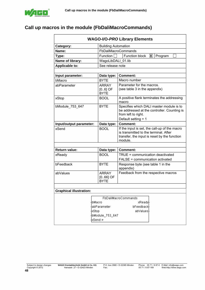
It is possible with module FbDaliMacroCommands to call up the macros stored in the DALI Multi-Master module.
The macro number is selected at input "bMacro“. The related parameters are set via the array "abParameter“.
Addressing can be prematurely terminated for the addressing macros via the input "xStop“.
The macros are called up, when input "xSend“ is set to TRUE. After transmitting the macro parameters to the module, input "xSend“ is automatically reset.
The DALI module with which this function block must communicate is selected at input "bModule_753_647".
The "xReady" output signals whether the module is active. As long as "xReady" is FALSE, no further action is taken by the function block.
The output “bFeedback” outputs a numeric code with the response. Numeric codes are listed in Table 1 in the Appendix.
Output "abValues“ delivers the appropriate results depending on the macro. Feedback from the ECG (raw value)

DALI Dimming Level -> Dimming Level Percent (FuPercentDimmValue)
Subject to design changes WAGO Kontakttechnik GmbH & Co. KG P:O. box 2880 • D-32385 Minden Phone: 05 71 / 8 87-0 E-Mail: [email protected] Copyright © 2012 Hansastr. 27 • D-32423 Minden Fax.: 05 71 / 8 87-169 Web:http://www.wago.com
50
08 Conversions
DALI Dimming Level -> Dimming Level Percent (FuPercentDimmValue)
WAGO-I/O-PRO Library Elements
Category: Building Automation
Name: FuPercentDimmValue
Type: Funktion X Function block Program
Name of library: WagoLibDALI_01.lib
Applicable to: See release note
Input parameter: Data type: Comment:
bRawValue BYTE DALI dimming level of 0 - 255
Return value: Data type: Comment:
FuPercentDimmValue REAL Output of the dimming level [%]
Graphical illustration:
Function description:
This function block converts the DALI dimming level (0 – 255) into a dimming level of 0 – 100 percent.
Dimming Level Percent -> DALI Dimming Level (FuDaliDimmValue)
WAGO-I/O-PRO Library Elements
Category: Building Automation
Name: FuDaliDimmValue
Type: Funktion X Function block Program
Name of library: WagoLibDALI_01.lib
Applicable to: See release note
Input parameter: Data type: Comment:
rPercent REAL Input of the dimming level [%]
Return value: Data type: Comment:
FuDaliDimmValue BYTE Output of the DALI dimming level (0 – 255)
Graphical illustration:
Function description:
This function block converts a dimming level of 0 – 100 percent into a DALI dimming level (0 – 255).

Numeric code "bFeedback"
Subject to design changes WAGO Kontakttechnik GmbH & Co. KG P:O. box 2880 • D-32385 Minden Phone: 05 71 / 8 87-0 E-Mail: [email protected] Copyright © 2012 Hansastr. 27 • D-32423 Minden Fax: 05 71 / 8 87-169 Web:http://www.wago.com
51
Appendix
Numeric code "bFeedback"
Table 1
Feedback from the module 0 OK 1 The last command sent is not supported by the module. 2 Invalid command 3 No virtual group available or max. number of participants exceeded 4 Several devices respond at the same time (frame error) 5 No response from the device (timeout) or module initialize 6 Internal error in the sequence number 7 Intermediate messages (e.g. Specify new short address) 8 Function aborted (e.g. addressing terminated prematurely) 9 The module has checked the command for plausibility and rejected
the command. 10 Collision detected when sending 11 Internal database is invalid 12 Error when copying to the module database 13 Receive buffer overflow 14 Status message from the module 15 Unaddressed devices found 16 Not all control gears could be addressed. Addressing must be
restarted. 17 Transmission buffer in the terminal block is full 18 Error in front end controller 19 Wrong sequnce ID
Feedback from the function blocks
100 Wrong address (short or group address) 101 Global reset of the function blocks was sent 102 Mailbox error 103 DALI module not recognized (e.g. master module was not called
up) 104 Error during automatic module identification (mod_com.lib) 105 DALI power not available 106 Interface errors in the terminal block (re-initialization) 107 Control Gears are already selected (physical selection) 108 Mailbox could not be initialized 109 Invalid command
Feedback from the mailbox
200 OK 201 Mailbox is not ready yet 202 Invalid command 203 Invalid configuration 204 Service rejected 205 Buffer full 206 Unexpected error on the module side 207 General error

Command set for FbDaliControlGearCommands
Subject to design changes WAGO Kontakttechnik GmbH & Co. KG P:O. box 2880 • D-32385 Minden Phone: 05 71 / 8 87-0 E-Mail: [email protected] Copyright © 2012 Hansastr. 27 • D-32423 Minden Fax.: 05 71 / 8 87-169 Web:http://www.wago.com
52
Command set for FbDaliControlGearCommands
Table 2
Indirect control commands of the lamp power Command wCommand bSpecial Value
OFF 0 - UP 1 -
DOWN 2 - STEP UP 3 -
STEP DOWN 4 - RECALL MAX LEVEL 5 - RECALL MIN LEVEL 6 -
STEP DOWN AND OFF 7 - ON AND STEP UP 8 -
ENABLE DAPC SEQUENCE 9 - RESERVED 10 - 15 -
GO TO SCENE 16 - 31 - Configuration commands
RESET 32 - STORE ACTUAL LEVEL IN THE DTR 33 -
RESERVED 34 - 41 - STORE THE DTR AS MAX LEVEL 42 - STORE THE DTP AS MIN LEVEL 43 -
STORE THE DTR AS SYSTEM FAILURE LEVEL 44 - STORE THE DTR AS POWER ON LEVEL 45 -
STORE THE DTR AS FADE TIME 46 - STORE THE DTR AS FADE RATE 47 -
RESERVED 48 - 63 - STORE THE DTR AS SCENE 64 - 79 -
ADD TO GROUP 80 - 95 - REMOVE FROM GROUP 112 - 127 -
STORE DTR AS SHORT ADDRESS 128 - ENABLE WRITE MEMORY 129 -
RESERVED 130 - 143 - Query commands
QUERY STATUS 144 - QUERY CONTROL GEAR 145 - QUERY LAMP FAILURE 146 -
QUERY LAMP POWER ON 147 - QUERY LIMIT ERROR 148 - QUERY RESET STATE 149 -
QUERY MISSING SHORT ADDRESS 150 - QUERY VERSION NUMBER 151 -
QUERY CONTENT DTR 152 - QUERY DEVICE TYPE 153 -
QUERY PHYSICAL MINIMUM LEVEL 154 - QUERY POWER FAILURE 155 - QUERY CONTENT DTR1 156 - QUERY CONTENT DTR2 157 -
RESERVED 158 - 159 - QUERY ACTUAL LEVEL 160 -
QUERY MAX LEVEL 161 - QUERY MIN LEVEL 162 -
QUERY POWER ON LEVEL 163 - QUERY SYSTEM FAILURE LEVEL 164 -

Subject to design changes WAGO Kontakttechnik GmbH & Co. KG P:O. box 2880 • D-32385 Minden Phone: 05 71 / 8 87-0 E-Mail: [email protected] Copyright © 2012 Hansastr. 27 • D-32423 Minden Fax: 05 71 / 8 87-169 Web:http://www.wago.com
53
Command wCommand bSpecial Value
Query commands QUERY FADE TIME / FADE RATE 165 -
RESERVED 166 - 175 - QUERY SCENE LEVEL 176 - 191 - QUERY GROUPS 0 - 7 192 - QUERY GROUPS 8 - 15 193 -
QUERY RANDOM ADDRESS (H) 194 - QUERY RANDOM ADDRESS (M) 195 - QUERY RANDOM ADDRESS (L) 196 -
READ MEMORY LOCATION 197 - RESERVED 198 - 223 -
Device Type specific commands DEVIC TYPE SPECIFIC COMMANDS 224 - 254 DEVICE TYPE
QUERY EXTENDED VERSION NUMBER 255 DEVICE TYPE Special commands
TERMINATE 256 - DATA TRANSFER REGISTER (DTR) 257 VALUE
INITIALISE 258 VALUE RANDOMISE 259 - COMPARE 260 - WITHDRAW 261 - RESERVED 262 - 263 -
SEARCHADDRH 264 VALUE SEARCHADDRM 265 VALUE SEARCHADDRL 266 VALUE
PROGRAM SHORT ADDRESS 267 - VERIFY SHORT ADDRESS 268 - QUERY SHORT ADDRESS 269 -
PHYSICAL SELECTION 270 - RESERVED 271 VALUE
ENABLE DEVICE TYPE X 272 DEVICE TYPE DATA TRANSFER REGISTER 1 (DTR1) 273 VALUE DATA TRANSFER REGISTER 2 (DTR2) 274 VALUE
WRITE MEMORY LOCATION 275 VALUE

Command set for FbDaliMacroCommands
Subject to design changes WAGO Kontakttechnik GmbH & Co. KG P:O. box 2880 • D-32385 Minden Phone: 05 71 / 8 87-0 E-Mail: [email protected] Copyright © 2012 Hansastr. 27 • D-32423 Minden Fax.: 05 71 / 8 87-169 Web:http://www.wago.com
54
Command set for FbDaliMacroCommands
Table 3
Macro 1 Random addressing
Send abParameter[0] 0: All newly addressed operating units are set to the "reset value"
1: The operating units retain their settings abParameter[1] 0: Only non-addressed devices are addressed
1: All operating units are re-addressed abParameter[2] 0: The dimming value is changed during addressing (max. value)
1: The dimming value is not changed during addressing Receive
abValues[0] Macro used abValues[1] Number of addressed operating units abValues[2] First short address assigned abValues[3] Last short address assigned
Macro 2 Physical addressing
Send abParameter[0] 0: All newly addressed operating units are set to the "reset value"
1: The operating units retain their settings abParameter[1] 0: Only non-addressed devices are addressed
1: All operating units are re-addressed abParameter[2] 0: The dimming value is changed during addressing (max. value)
Receive
abValues[0] Macro used abValues[1] Number of addressed operating units abValues[2] First short address assigned abValues[3] Last short address assigned
Macro 3 Exchange short addresses
Send abParameter[0] Short address (0 – 63) to be exchanged must be available abParameter[1] Short address (0 – 63) to be exchanged can be available
Receive abValues[0] Macro used

Command set for FbDaliMacroCommands
Subject to design changes WAGO Kontakttechnik GmbH & Co. KG P:O. box 2880 • D-32385 Minden Phone: 05 71 / 8 87-0 E-Mail: [email protected] Copyright © 2012 Hansastr. 27 • D-32423 Minden Fax: 05 71 / 8 87-169 Web:http://www.wago.com
55
Macro 4 Send two commands successively
Send abParameter[0] Address of first command (according to IEC 62386) abParameter[1] First DALI command abParameter[2] Reserve abParameter[3] Address of second command (according to IEC 62386) abParameter[4] Second DALI command abParameter[5] Reserve abParameter[6] Number of repetitions (should always be zero)
Receive abValues[0] Macro used
Macro 5 Read serial number (8 bytes)
Send abParameter[0] Short address (0 – 63)
Receive abValues[0] Macro used abValues[1] Number of bytes read abValues[2] Serial number byte 8 abValues[3] Serial number byte 7 abValues[4] Serial number byte 6 abValues[5] Serial number byte 5 abValues[6] Serial number byte 4 abValues[7] Serial number byte 3 abValues[8] Serial number byte 2 abValues[9] Serial number byte 1
Macro 6 Synchronize module database
Send
Receive abValues[0] Macro used
Macro 7 Start flashing
Send abParameter[0] Address (0 – 96)
0 – 63 = Short address 0 – 63 64 – 95 = Group 0 – 31 96 = Broadcast
abParameter[1] Number of flashing periods Receive
abValues[0] Macro used

Command set for FbDaliMacroCommands
Subject to design changes WAGO Kontakttechnik GmbH & Co. KG P:O. box 2880 • D-32385 Minden Phone: 05 71 / 8 87-0 E-Mail: [email protected] Copyright © 2012 Hansastr. 27 • D-32423 Minden Fax.: 05 71 / 8 87-169 Web:http://www.wago.com
56
Macro 8 Stop flashing
Send abParameter[0] Address (0 – 96)
0 – 63 = Short address 0 – 63 64 – 95 = Group 0 – 31 96 = Broadcast
Receive abValues[0] Macro used
Macro 9 Start dimming
Send abParameter[0] Address (0 – 96)
0 – 63 = Short address 0 – 63 64 – 95 = Group 0 – 31 96 = Broadcast Bit 0.1 00 = Dimming only
01 = Start at the last dimming value 02 = Can be switched on via dimming
2 0 = Darker 1 = Brighter
3 0 = Light stays on when reaching the minimum value 1 = Light switches off when reaching the minimum value
4 0 = No check whether min / max value reached 1 = Check for min / max value
5 0 = No check of values 1 = Check whether min / max values were reached
abParameter[1]
6.7 Reserve Receive
abValues[0] Macro used
Macro 10 Stop dimming
Send abParameter[0] Address (0 – 96)
0 – 63 = Short address 0 – 63 64 – 95 = Group 0 – 31 96 = Broadcast
Receive abValues[0] Macro used
Macro 11 Delete virtual group
Send abParameter[0] Virtual group (16 – 31)
Receive abValues[0] Macro used

Command set for FbDaliMacroCommands
Subject to design changes WAGO Kontakttechnik GmbH & Co. KG P:O. box 2880 • D-32385 Minden Phone: 05 71 / 8 87-0 E-Mail: [email protected] Copyright © 2012 Hansastr. 27 • D-32423 Minden Fax: 05 71 / 8 87-169 Web:http://www.wago.com
57
Macro 12 Read device status
Send Bit 0 Short address available 1 Operating unit (ECG) is switched on
abParameter[0]
2 Reading a status bit abParameter[1] Bit number in the status byte, if abParameter[0] = 2
0 = State of the operating unit (ECG) 1 = Lamp error 2 = Lamp power on 3 = Query limit value error 4 = Transition process 5 = Query "Reset State“? 6 = Query short address is missing? 7 = Query "Power Failure"?
Receive abValues[0] Macro used abValues[1] Status short address 0 – 7 (bit coded) abValues[2] Status short address 8 – 15 (bit coded) abValues[3] Status short address 16 – 23 (bit coded) abValues[4] Status short address 24 – 31 (bit coded) abValues[5] Status short address 32 – 39 (bit coded) abValues[6] Status short address 40 – 47 (bit coded) abValues[7] Status short address 48 – 55 (bit coded) abValues[8] Status short address 56 – 63 (bit coded)
Macro 13 Read memory bank
Send abParameter[0] Short address (0 – 63) abParameter[1] Number of memory bank abParameter[2] Starting value (Offset) abParameter[3] Number of bytes to be read
Receive abValues[0] Macro used abValues[1] Number of bytes read abValues[2] 1st read byte from the memory bank abValues[3] 2nd read byte from the memory bank
etc. abValues[65] 64th read byte from the memory bank
Macro 14 Write in memory bank
Send abParameter[0] Short address (0 – 63) abParameter[1] Number of memory bank abParameter[2] Starting value (Offset) abParameter[3] Number of bytes to write abParameter[4] First byte to write abParameter[5] Second byte to write abParameter[6] Third byte to write
Receive abValues[0] Macro used

Command set for FbDaliMacroCommands
Subject to design changes WAGO Kontakttechnik GmbH & Co. KG P:O. box 2880 • D-32385 Minden Phone: 05 71 / 8 87-0 E-Mail: [email protected] Copyright © 2012 Hansastr. 27 • D-32423 Minden Fax.: 05 71 / 8 87-169 Web:http://www.wago.com
58
Macro 15 Write module database into EEPROM
Send abParameter[0] No significance
Receive abValues[0] Macro used
Macro 16 Read module database from EEPROM
Send abParameter[0] No significance
Receive abValues[0] Macro used
Macro 17 Read operating hours
Send abParameter[0] Short address (0 – 63)
Receive abValues[0] Macro used abValues[1] First byte of operating hours (LSB) abValues[2] Second byte of operating hours abValues[3] Third byte of operating hours (MSB)
Macro 18 Delete operating hours
Send abParameter[0] Short address (0 – 63)
Receive abValues[0] Macro used
Macro 19 Add short address to virtual group
Send abParameter[0] Short address (0 – 63) abParameter[1] Virtual group (16 – 31)
Receive abValues[0] Macro used
Macro 20 Remove short address from virtual group
Send abParameter[0] Short address (0 – 63) abParameter[1] Virtual group (16 – 31)
Receive abValues[0] Macro used

Command set for FbDaliMacroCommands
Subject to design changes WAGO Kontakttechnik GmbH & Co. KG P:O. box 2880 • D-32385 Minden Phone: 05 71 / 8 87-0 E-Mail: [email protected] Copyright © 2012 Hansastr. 27 • D-32423 Minden Fax: 05 71 / 8 87-169 Web:http://www.wago.com
59
Macro 21 Check for subscription in virtual group
Send abParameter[0] Short address (0 – 63)
Receive abValues[0] Macro used abValues[1] Virtual group 16 - 23 (bit coded) abValues[2] Virtual group 24 - 31 (bit coded)
Macro 23 Read module register
Send abParameter[0] First register to read abParameter[1] Number of registers to read (max. 16)
Receive abValues[0] Macro used abValues[1] Number of read registers abValues[2] Register value 1 (MSB) abValues[3] Register value 1 (LSB)
etc. abValues[32] Register 16 (MSB) abValues[33] Register 16 (LSB)
Macro 24 Write module register
Send abParameter[0] Register to write (32 – 41) abParameter[1] Register value (MSB) abParameter[2] Register value (LSB)
Receive abValues[0] Macro used
Macro 25 Send configuration commands
Send abParameter[0] Reserve abParameter[1] Content of data transfer register (DTR) abParameter[2] Address of second command (according to IEC 62386) abParameter[3] DALI command
Receive abValues[0] Macro used
Macro 26 Switch own power supply on / off
Send abParameter[0] 0 = On
1 = Off Receive
abValues[0] Macro used

Command set for FbDaliMacroCommands
Subject to design changes WAGO Kontakttechnik GmbH & Co. KG P:O. box 2880 • D-32385 Minden Phone: 05 71 / 8 87-0 E-Mail: [email protected] Copyright © 2012 Hansastr. 27 • D-32423 Minden Fax.: 05 71 / 8 87-169 Web:http://www.wago.com
60
Macro 28 Read group subscribers
Send abParameter[0] Group (0 – 31)
Receive abValues[0] Macro used abValues[1] Short address 0 – 7 (bit coded) abValues[2] Short address 8 – 15 (bit coded) abValues[3] Short address 16 – 23 (bit coded) abValues[4] Short address 24 – 31 (bit coded) abValues[5] Short address 32 – 39 (bit coded) abValues[6] Short address 40 – 47 (bit coded) abValues[7] Short address 48 – 55 (bit coded) abValues[8] Short address 56 – 63 (bit coded)
Macro 29 Configuration with DTR, DTR1 and DTR2
Send abParameter[0] Content of data transfer register (DTR2) abParameter[1] Content of data transfer register (DTR1) abParameter[2] Content of data transfer register (DTR) abParameter[3] Address (according to IEC 62386) abParameter[4] DALI command
Bit 0 Data transfer register (DTR1) will be written abParameter[5] 1 Data transfer register (DTR2) will be written
abParameter[6] Device Type Receive
abValues[0] Macro used

Reset values
Subject to design changes WAGO Kontakttechnik GmbH & Co. KG P:O. box 2880 • D-32385 Minden Phone: 05 71 / 8 87-0 E-Mail: [email protected] Copyright © 2012 Hansastr. 27 • D-32423 Minden Fax: 05 71 / 8 87-169 Web:http://www.wago.com
61
Reset values
Table 4
Parameter Reset Value
Min-level Physically smallest value
Max-level 100 %
Fade rate 7
Fade time 0
Power on level 100 %
System failure level 100 %
Group assignment All deleted
Scene values No scene defined
Fade Time and Fade Rate
Table 5
Value Fade time [s] Fate rate [fades/s]
0 < 0.707 not usable
1 0.707 357.796
2 1.00 253.00
3 1.414 178.898
4 2.00 126.50
5 2.828 89.449
6 4.00 63.25
7 5.657 44.725
8 8.00 31.625
9 11.314 22.362
10 16.00 15.813
11 22.627 11.181
12 32.00 7.906
13 45.255 5.591
14 64.00 3.953
15 90.51 2.795

WAGO Kontakttechnik GmbH & Co. KG PO Box 2880 • D-32385 Minden Hansastraße 27 • D-32423 Minden Phone: +49 (0) 571/8 87 – 0 Fax: +49 (0) 571/8 87 – 1 69 E-Mail: [email protected] Internet: http://www.wago.com