courage sv710-740 - kohlerengines.com.cnkohlerengines.com.cn/onlinecatalog/pdf/tp_2574_a.pdf ·...
TRANSCRIPT
SERVICE MANUAL
VERTICAL CRANKSHAFT
COURAGE SV710-740COURAGE PRO SV810-840

Contents
Section 1. Safety and General Information .............................................................................
Section 2. Tools & Aids.............................................................................................................
Section 3. Troubleshooting ......................................................................................................
Section 4. Air Cleaner and Air Intake System.........................................................................
Section 5. Fuel System and Governor.....................................................................................
Section 6. Lubrication System .................................................................................................
Section 7. Electrical System and Components ......................................................................
Section 8. Disassembly.............................................................................................................
Section 9. Inspection and Reconditioning..............................................................................
Section 10. Reassembly............................................................................................................
Section 11. Emission Compliance Systems............................................................................
1
2
3
4
5
6
7
8
9
10
11

1.1
Section 1Safety and General Information
1Section 1
Safety and General Information
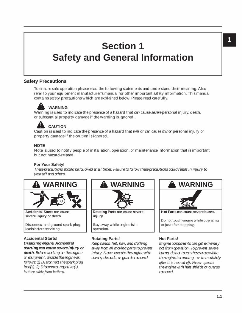
Safety PrecautionsTo ensure safe operation please read the following statements and understand their meaning. Also refer to your equipment manufacturer's manual for other important safety information. This manual contains safety precautions which are explained below. Please read carefully.
WARNINGWarning is used to indicate the presence of a hazard that can cause severe personal injury, death, or substantial property damage if the warning is ignored.
CAUTIONCaution is used to indicate the presence of a hazard that will or can cause minor personal injury or property damage if the caution is ignored.
NOTENote is used to notify people of installation, operation, or maintenance information that is important but not hazard-related.
For Your Safety!These precautions should be followed at all times. Failure to follow these precautions could result in injury to yourself and others.
Rotating Parts can cause severe injury.
Stay away while engine is in operation.
WARNING
Rotating Parts!Keep hands, feet, hair, and clothing away from all moving parts to prevent injury. Never operate the engine with covers, shrouds, or guards removed.
Hot Parts can cause severe burns.
Do not touch engine while operating
WARNING
Hot Parts!Engine components can get extremely hot from operation. To prevent severe burns, do not touch these areas while the engine is running - or immediately
the engine with heat shields or guards removed.
Accidental Starts can cause severe injury or death.
Disconnect and ground spark plug leads before servicing.
WARNING
Accidental Starts!Disabling engine. Accidental starting can cause severe injury or death. Before working on the engine or equipment, disable the engine as follows: 1) Disconnect the spark plug lead(s). 2) Disconnect negative (-)
1.2
Section 1Safety and General Information
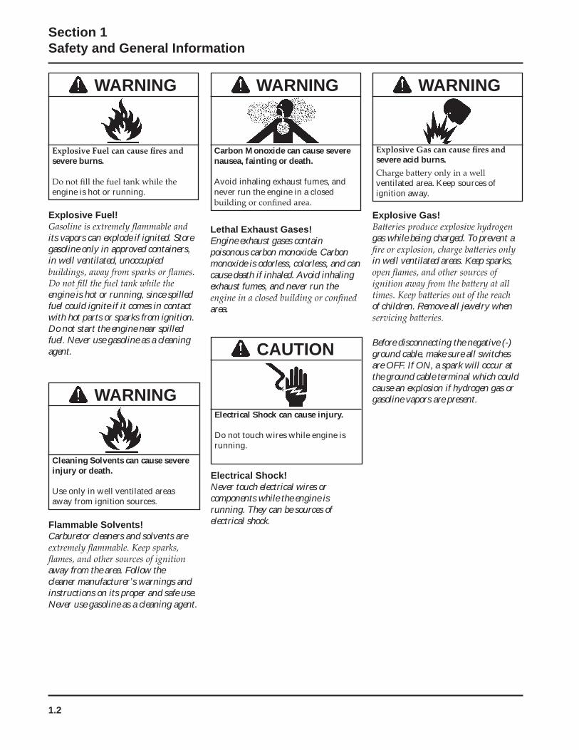
Carbon Monoxide can cause severe nausea, fainting or death.
Avoid inhaling exhaust fumes, and never run the engine in a closed
WARNING WARNING
severe acid burns.
ventilated area. Keep sources of ignition away.
Lethal Exhaust Gases!Engine exhaust gases contain poisonous carbon monoxide. Carbon monoxide is odorless, colorless, and can cause death if inhaled. Avoid inhaling exhaust fumes, and never run the
area.
Explosive Gas!
gas while being charged. To prevent a
in well ventilated areas. Keep sparks,
of children. Remove all jewelry when
Before disconnecting the negative (-) ground cable, make sure all switches are OFF. If ON, a spark will occur at the ground cable terminal which could cause an explosion if hydrogen gas or gasoline vapors are present.
severe burns.
engine is hot or running.
WARNING
Explosive Fuel!
its vapors can explode if ignited. Store gasoline only in approved containers, in well ventilated, unoccupied
engine is hot or running, since spilled fuel could ignite if it comes in contact with hot parts or sparks from ignition. Do not start the engine near spilled fuel. Never use gasoline as a cleaning agent.
Cleaning Solvents can cause severe injury or death.
Use only in well ventilated areas away from ignition sources.
WARNING
Flammable Solvents!Carburetor cleaners and solvents are
away from the area. Follow the cleaner manufacturer’s warnings and instructions on its proper and safe use. Never use gasoline as a cleaning agent.
Electrical Shock can cause injury.
Do not touch wires while engine is running.
CAUTION
Electrical Shock!Never touch electrical wires or components while the engine is running. They can be sources of electrical shock.
1.3
Section 1Safety and General Information
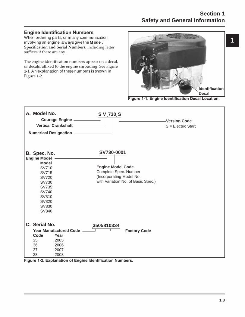
1When ordering parts, or in any communication involving an engine, always give the Model,
1-1. An explanation of these numbers is shown in
B. Spec. No.Engine Model Model
SV710SV715SV720 SV730 SV735 SV740SV810SV820SV830SV840
Engine Model CodeComplete Spec. Number (Incorporating Model No. with Variation No. of Basic Spec.)
C. Serial No.Year Manufactured CodeCode Year35 200536 200637 200738 2008
Factory Code3505810334
SV730-0001
A. Model No.Version Code
S V 730 SCourage Engine
Vertical Crankshaft S = Electric Start
1.4
Section 1Safety and General Information
Oil RecommendationsUsing the proper type and weight of oil in the crankcase is extremely important. So is checking oil
correct oil, or using dirty oil, causes premature engine wear and failure.
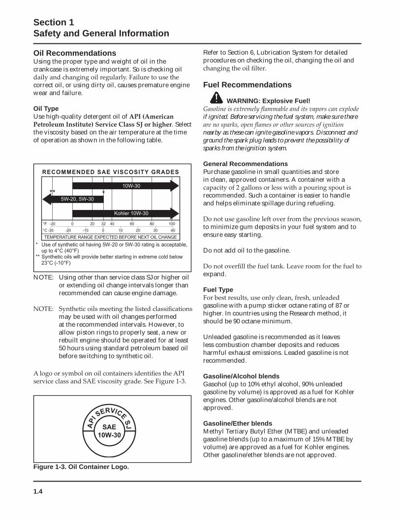
Oil TypeUse high-quality detergent oil of
. Select the viscosity based on the air temperature at the time of operation as shown in the following table.
Refer to Section 6, Lubrication System for detailed procedures on checking the oil, changing the oil and
Fuel Recommendations
WARNING: Explosive Fuel!
if ignited. Before servicing the fuel system, make sure there
nearby as these can ignite gasoline vapors. Disconnect and ground the spark plug leads to prevent the possibility of sparks from the ignition system.
General RecommendationsPurchase gasoline in small quantities and store in clean, approved containers. A container with a
recommended. Such a container is easier to handle and helps eliminate spillage during refueling.
to minimize gum deposits in your fuel system and to ensure easy starting.
Do not add oil to the gasoline.
expand.
Fuel Type
gasoline with a pump sticker octane rating of 87 or higher. In countries using the Research method, it should be 90 octane minimum.
Unleaded gasoline is recommended as it leaves less combustion chamber deposits and reduces harmful exhaust emissions. Leaded gasoline is not recommended.
Gasoline/Alcohol blendsGasohol (up to 10% ethyl alcohol, 90% unleaded gasoline by volume) is approved as a fuel for Kohler engines. Other gasoline/alcohol blends are not approved.
Gasoline/Ether blendsMethyl Tertiary Butyl Ether (MTBE) and unleaded gasoline blends (up to a maximum of 15% MTBE by volume) are approved as a fuel for Kohler engines. Other gasoline/ether blends are not approved.
NOTE: Using other than service class SJ or higher oil or extending oil change intervals longer than recommended can cause engine damage.
may be used with oil changes performed at the recommended intervals. However, to allow piston rings to properly seat, a new or rebuilt engine should be operated for at least 50 hours using standard petroleum based oil before switching to synthetic oil.
Figure 1-3. Oil Container Logo.
5W-20, 5W-30
RECOMMENDED SAE VISCOSITY GRADES
10W-30
Kohler 10W-30
°F -20 0 20 32 40 60 80 100
°C -30 -20 -10 0 10 20 30 40
TEMPERATURE RANGE EXPECTED BEFORE NEXT OIL CHANGE * Use of synthetic oil having 5W-20 or 5W-30 rating is acceptable,
up to 4°C (40°F)** Synthetic oils will provide better starting in extreme cold below
23°C ( -10°F)
** *
SAE10W-30
API
SERVICESJ
1.5
Section 1Safety and General Information
1Periodic Maintenance Instructions
WARNING: Accidental Starts!Disabling engine. Accidental starting can cause severe injury or death. Before working on the engine or equipment,
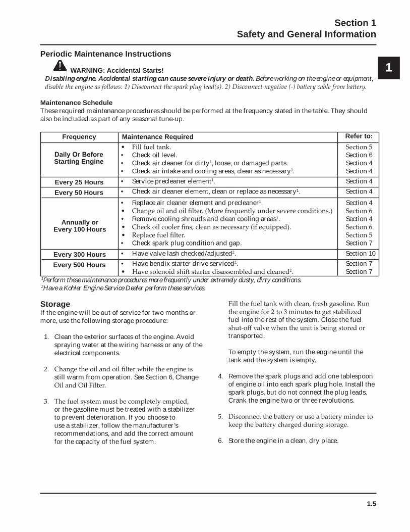
Maintenance ScheduleThese required maintenance procedures should be performed at the frequency stated in the table. They should also be included as part of any seasonal tune-up.
StorageIf the engine will be out of service for two months or more, use the following storage procedure:
1. Clean the exterior surfaces of the engine. Avoid spraying water at the wiring harness or any of the electrical components.
still warm from operation. See Section 6, Change
or the gasoline must be treated with a stabilizer to prevent deterioration. If you choose to use a stabilizer, follow the manufacturer’s recommendations, and add the correct amount for the capacity of the fuel system.
fuel into the rest of the system. Close the fuel
transported.
To empty the system, run the engine until the tank and the system is empty.
4. Remove the spark plugs and add one tablespoon of engine oil into each spark plug hole. Install the spark plugs, but do not connect the plug leads. Crank the engine two or three revolutions.
6. Store the engine in a clean, dry place.
1Perform these maintenance procedures more frequently under extremely dusty, dirty conditions.2Have a Kohler Engine Service Dealer perform these services.
Frequency Maintenance Required
• Check oil level. Section 6• Check air cleaner for dirty1, loose, or damaged parts. Section 4• Check air intake and cooling areas, clean as necessary1. Section 4• Service precleaner element1. Section 4
Starting Engine
Every 25 Hours
• Replace air cleaner element and precleaner¹. Section 4
• Remove cooling shrouds and clean cooling areas¹. Section 4
• Check spark plug condition and gap. Section 7
Every 50 Hours • Check air cleaner element, clean or replace as necessary¹. Section 4
Annually or Every 100 Hours
• Have valve lash checked/adjusted . Section 10Every 300 HoursEvery 500 Hours • Have bendix starter drive serviced . Section 7
. Section 7
Refer to:
1.6
Section 1Safety and General Information
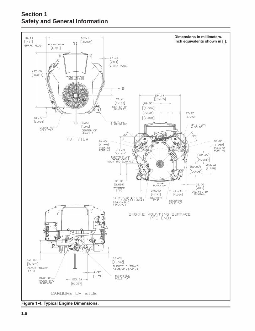
Inch equivalents shown in [ ].
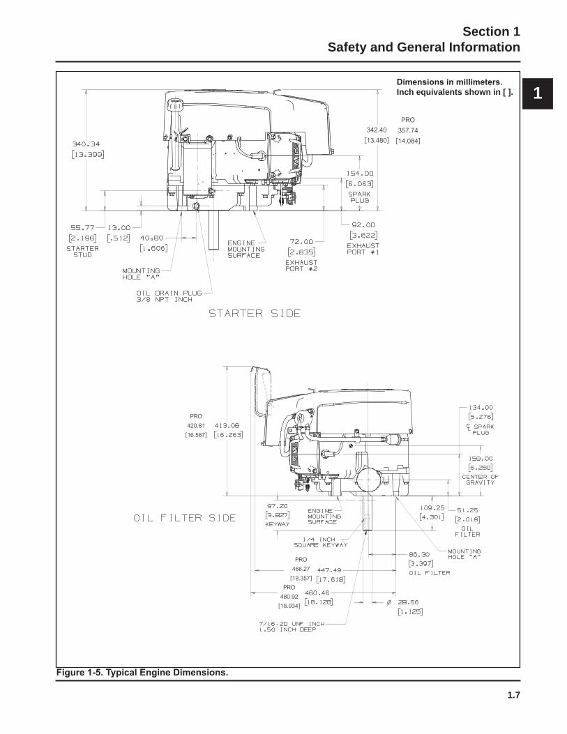
1.7
Section 1Safety and General Information
1Inch equivalents shown in [ ].
PRO420.81[16.567]
PRO480.92[18.934]
PRO466.27[18.357]
PRO357.74[14.084]
342.40[13.480]
1.8
Section 1Safety and General Information
1
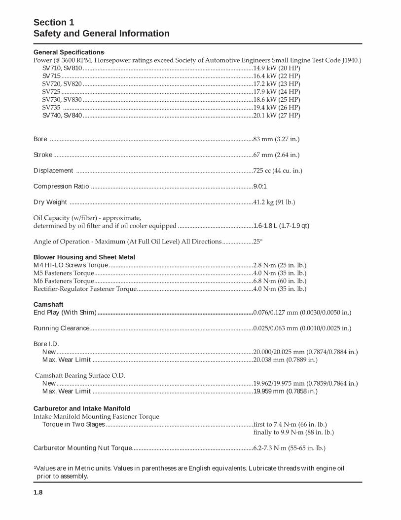
SV710, SV810 ........................................................................................................SV715 .....................................................................................................................
.............................................................................................................................................................................................................................
............................................................................................................................................................................................................................
SV740, SV840 ........................................................................................................
Bore ............................................................................................................................
Stroke ..........................................................................................................................
Displacement ............................................................................................................
Compression Ratio ...................................................................................................9.0:1
Dry Weight ................................................................................................................
..............................................1.6-1.8 L (1.7-1.9 qt)
...................
Blower Housing and Sheet MetalM4 HI-LO Screws Torque ........................................................................................
.................................................................................................
........................................................................................................................................................................
CamshaftEnd Play (With Shim) ...............................................................................................
Running Clearance....................................................................................................
Bore I.D.New........................................................................................................................Max. Wear Limit ..................................................................................................
New........................................................................................................................Max. Wear Limit ..................................................................................................19.959 mm (0.7858 in.)
Carburetor and Intake Manifold
Torque in Two Stages ..........................................................................................
Carburetor Mounting Nut Torque..........................................................................
¹Values are in Metric units. Values in parentheses are English equivalents. Lubricate threads with engine oil prior to assembly.
1.9
Section 1Safety and General Information
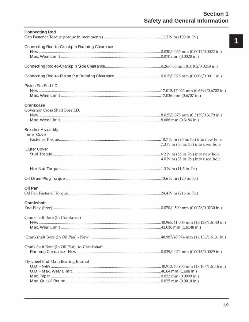
1Connecting Rod
.........................................................
Connecting Rod-to-Crankpin Running ClearanceNew........................................................................................................................Max. Wear Limit ..................................................................................................
Connecting Rod-to-Crankpin Side Clearance.......................................................
Connecting Rod-to-Piston Pin Running Clearance..............................................
Piston Pin End I.D.New........................................................................................................................Max. Wear Limit ..................................................................................................
Crankcase
New........................................................................................................................Max. Wear Limit ..................................................................................................
Breather Assembly Inner Cover
....................................................................................................
Outer Cover Stud Torque ..........................................................................................................
Hex Nut Torque ...................................................................................................
Oil Drain Plug Torque .............................................................................................
Oil Pan...........................................................................................
Crankshaft..........................................................................................................
New........................................................................................................................Max. Wear Limit ..................................................................................................41.016 mm (1.6148 in.)
......................................................................
Running Clearance - New ..................................................................................
O.D. - New............................................................................................................O.D. - Max. Wear Limit.......................................................................................40.84 mm (1.608 in.)Max. Taper ............................................................................................................Max. Out-of-Round .............................................................................................
1.10
Section 1Safety and General Information
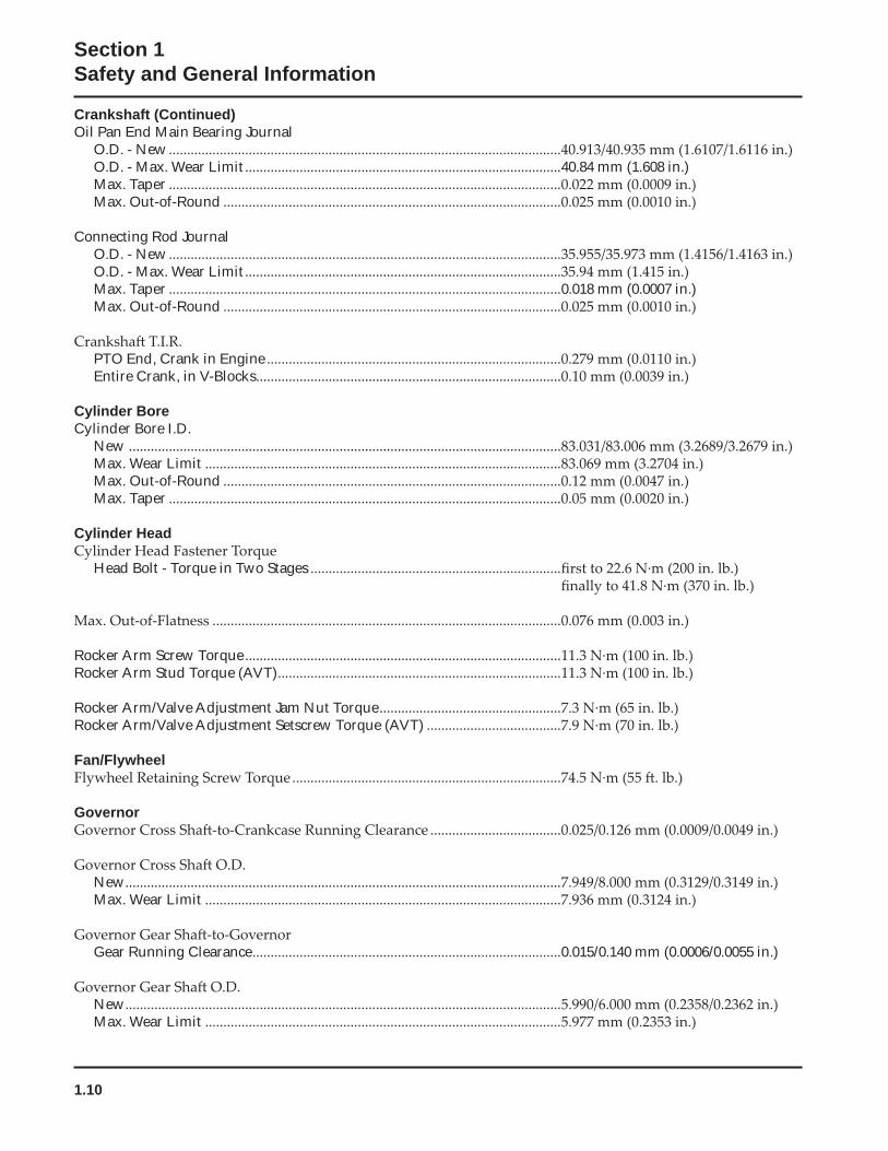
Crankshaft (Continued)Oil Pan End Main Bearing Journal
O.D. - New............................................................................................................O.D. - Max. Wear Limit.......................................................................................40.84 mm (1.608 in.)Max. Taper ............................................................................................................Max. Out-of-Round .............................................................................................
Connecting Rod JournalO.D. - New............................................................................................................O.D. - Max. Wear Limit.......................................................................................Max. Taper ............................................................................................................0.018 mm (0.0007 in.)Max. Out-of-Round .............................................................................................
PTO End, Crank in Engine .................................................................................Entire Crank, in V-Blocks....................................................................................
Cylinder BoreCylinder Bore I.D.
New .......................................................................................................................Max. Wear Limit ..................................................................................................Max. Out-of-Round .............................................................................................Max. Taper ............................................................................................................
Cylinder Head
Head Bolt - Torque in Two Stages .....................................................................
................................................................................................
Rocker Arm Screw Torque.......................................................................................Rocker Arm Stud Torque (AVT)..............................................................................
Rocker Arm/Valve Adjustment Jam Nut Torque..................................................Rocker Arm/Valve Adjustment Setscrew Torque (AVT) .....................................
Fan/Flywheel..........................................................................
Governor....................................
New........................................................................................................................Max. Wear Limit ..................................................................................................
Gear Running Clearance.....................................................................................0.015/0.140 mm (0.0006/0.0055 in.)
New........................................................................................................................Max. Wear Limit ..................................................................................................
1.11
Section 1Safety and General Information
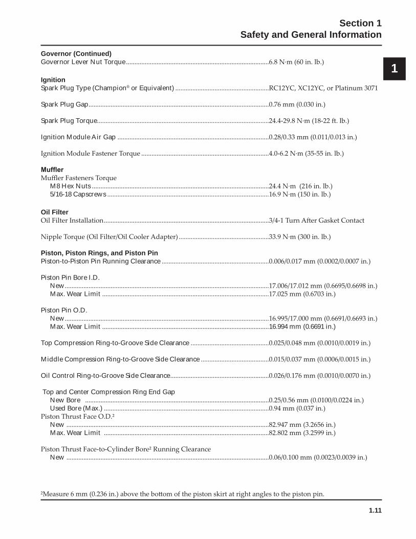
1Governor (Continued)Governor Lever Nut Torque....................................................................................
IgnitionSpark Plug Type (Champion® or Equivalent) .......................................................
Spark Plug Gap..........................................................................................................
Spark Plug Torque.....................................................................................................
Ignition Module Air Gap .........................................................................................
...........................................................................
M8 Hex Nuts ........................................................................................................5/16-18 Capscrews ...............................................................................................
Oil Filter.................................................................................................
.....................................................
Piston, Piston Rings, and Piston PinPiston-to-Piston Pin Running Clearance ...............................................................
Piston Pin Bore I.D.New........................................................................................................................Max. Wear Limit ..................................................................................................
Piston Pin O.D.New........................................................................................................................Max. Wear Limit ..................................................................................................16.994 mm (0.6691 in.)
Top Compression Ring-to-Groove Side Clearance ..............................................
Middle Compression Ring-to-Groove Side Clearance ........................................
Oil Control Ring-to-Groove Side Clearance..........................................................
Top and Center Compression Ring End GapNew Bore ............................................................................................................Used Bore (Max.) .................................................................................................
New .......................................................................................................................Max. Wear Limit .................................................................................................
New .......................................................................................................................
1.12
Section 1Safety and General Information
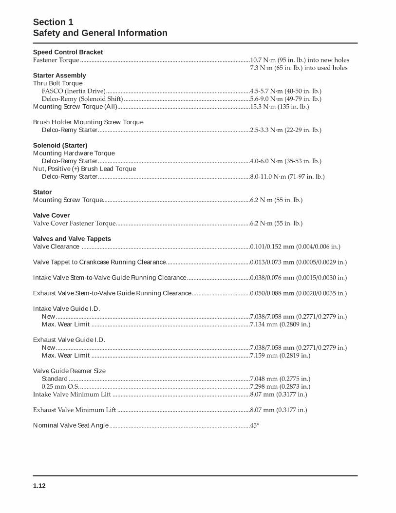
Speed Control Bracket.........................................................................................................
Starter AssemblyThru Bolt Torque
.......................................................................................................................................................................
Mounting Screw Torque (All)..................................................................................
Brush Holder Mounting Screw TorqueDelco-Remy Starter..............................................................................................
Solenoid (Starter)Mounting Hardware Torque
Delco-Remy Starter..............................................................................................Nut, Positive (+) Brush Lead Torque
Delco-Remy Starter..............................................................................................
StatorMounting Screw Torque...........................................................................................
Valve Cover...................................................................................
Valves and Valve TappetsValve Clearance ........................................................................................................
Valve Tappet to Crankcase Running Clearance....................................................
Intake Valve Stem-to-Valve Guide Running Clearance .......................................
Exhaust Valve Stem-to-Valve Guide Running Clearance....................................
Intake Valve Guide I.D.New........................................................................................................................Max. Wear Limit ..................................................................................................
Exhaust Valve Guide I.D.New........................................................................................................................Max. Wear Limit ..................................................................................................
Valve Guide Reamer SizeStandard................................................................................................................
..............................................................................................................................................................................................
..................................................................................
Nominal Valve Seat Angle .......................................................................................
1.13
Section 1Safety and General Information
1
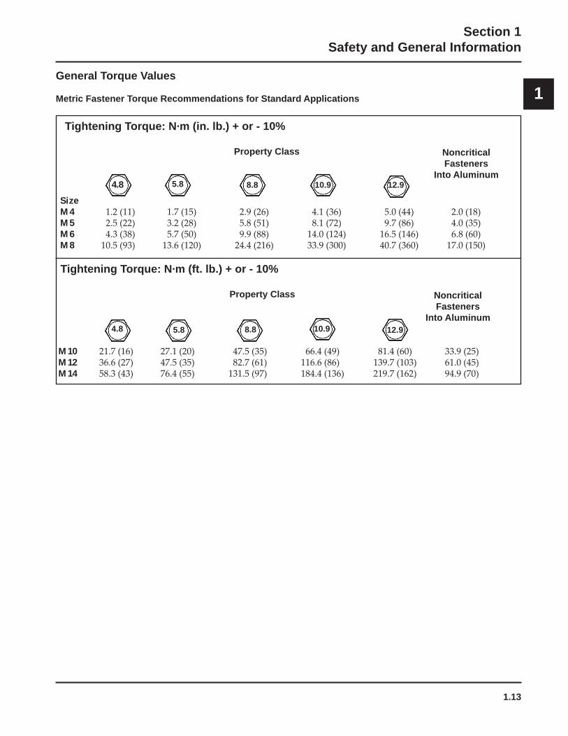
Tightening Torque: N·m (in. lb.) + or - 10%
Property Class NoncriticalFasteners
Into Aluminum
SizeM4M5M6M8
Tightening Torque: N·m (ft. lb.) + or - 10%
Property Class NoncriticalFasteners
Into Aluminum
M10M12M14
5.8 8.8 10.9 12.9
4.8 5.8 10.9 12.9
4.8
8.8
General Torque Values
Metric Fastener Torque Recommendations for Standard Applications
1.14
Section 1Safety and General Information
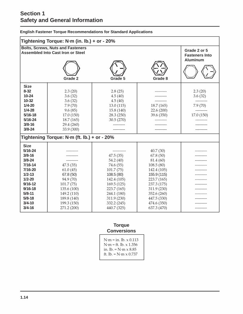
English Fastener Torque Recommendations for Standard Applications
Grade 2 or 5Fasteners IntoAluminum
Size8-3210-2410-321/4-201/4-285/16-185/16-243/8-163/8-24
Size5/16-243/8-163/8-247/16-147/16-201/2-13 67.8 (50) 108.5 (80) 155.9 (115) ---------1/2-209/16-129/16-185/8-115/8-183/4-103/4-16
Tightening Torque: N·m (ft. lb.) + or - 20%
Tightening Torque: N·m (in. lb.) + or - 20%
Grade 2 Grade 5 Grade 8
Bolts, Screws, Nuts and FastenersAssembled Into Cast Iron or Steel
TorqueConversions
2.1
Section 2Tools & Aids
2
Section 2Tools & Aids
Separate Tool Suppliers:Kohler ToolsContact your source
SE Tools
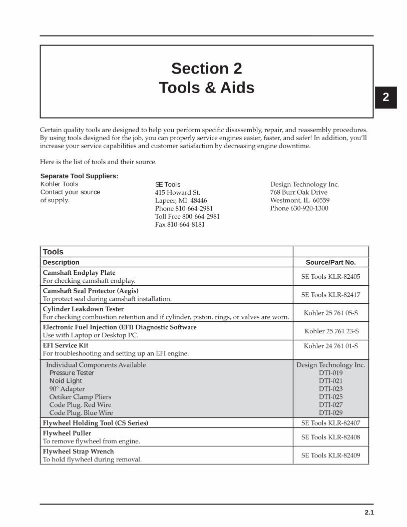
ToolsDescription Source/Part No.
Pressure Tester Noid Light
2.2
Section 2Tools & Aids
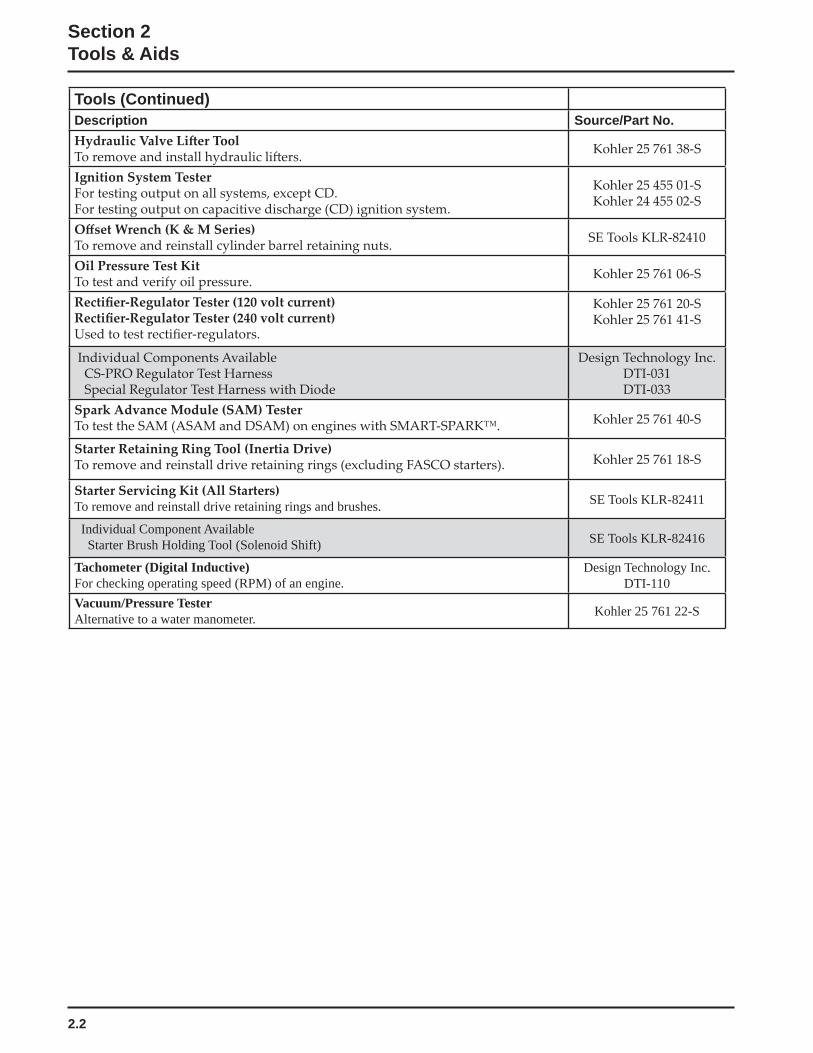
Tools (Continued)Description Source/Part No.
To remove and reinstall drive retaining rings and brushes. SE Tools KLR-82411
Individual Component Available Starter Brush Holding Tool (Solenoid Shift) SE Tools KLR-82416
Tachometer (Digital Inductive)For checking operating speed (RPM) of an engine.
Design Technology Inc.DTI-110
Vacuum/Pressure TesterAlternative to a water manometer. Kohler 25 761 22-S
2.3
Section 2Tools & Aids
2
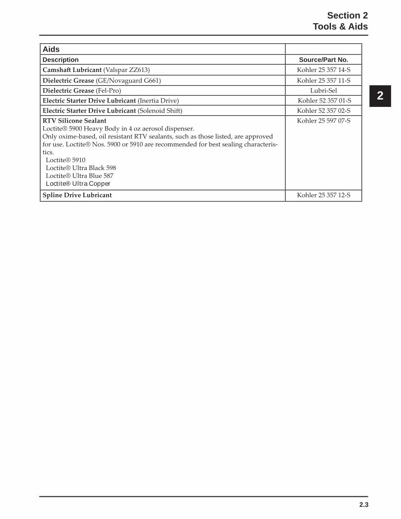
AidsDescription Source/Part No.
Loctite® Ultra Copper
2.4
Section 2Tools & Aids
Special Tools You Can Make
Flywheel Holding Tool
Figure 2-1. Flywheel Holding Tool.
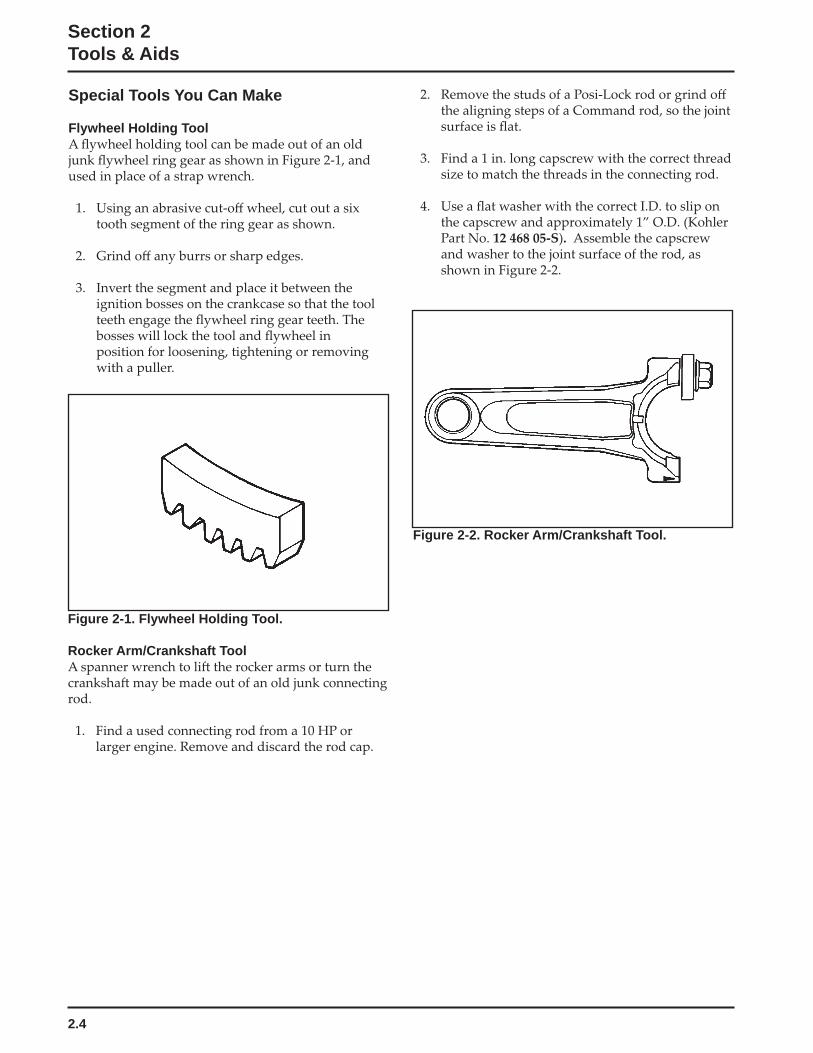
Rocker Arm/Crankshaft Tool
Figure 2-2. Rocker Arm/Crankshaft Tool.
3.1
Section 3Troubleshooting
3
Section 3Troubleshooting
Troubleshooting GuideWhen troubles occur, be sure to check the simple
considered. For example, a starting problem could be
Engine Cranks But Will Not Start
9. DSAI or DSAM
mode.
hose.
Engine Starts But Does Not Keep Running
4. Loose wires or connections that short the kill
hose.
mode.
Engine Starts Hard
7. Low compression.
9. Weak spark.
restricted.
Engine Will Not Crank
7. Seized internal engine components.
Engine Runs But Misses
2. Spark plug lead disconnected.
ground the ignition kill circuit.
9. DSAI or DSAM
3.2
Section 3Troubleshooting
Engine Will Not Idle
7. Low compression.
problem.
Engine Overheats
shrouds clogged.
7. DSAI or DSAM
Engine Knocks
4. Internal wear or damage.
Engine Loses Power
8. Low compression.9. Exhaust restriction.
10. DSAI or DSAM
Engine Uses Excessive Amount of Oil
3. Breather reed broken.4. Worn or broken piston rings.
Oil Leaks from Oil Seals, Gaskets
2. Breather reed broken.
5. Restricted exhaust.
External Engine Inspection
when it is disassembled.
•
•
•
clogged. These could indicate that the engine has
•
•
3.3
Section 3Troubleshooting
3
•
drainage.
Cleaning the Engine
engine parts. When such a cleaner is used, followthe manufacturer’s instructions and safety precautions carefully.
the engine is reassembled and placed into operation.
Basic Engine Tests
Crankcase Vacuum Test
crankcase when the engine is operating. Pressure
the kits.
2. Start the engine and run at no-load high speed
tube.
10.2 cm (4 in.) open side.
table on page 3.4.
before stopping the engine.
opening.
the hole in the adapter.
4. Start the engine and bring it up to operating
is to the
the rightpresent.
pressure is present, check the table on page 3.4
3.4
Section 3Troubleshooting
Compression Test
Cylinder Leakdown Test
adapter hose, and a holding tool.
Leakdown Test Instructions
engine.
the compression stroke. Hold the engine in this position while testing. The holding tool supplied
is perpendicular to both the holding tool and
direction.
4. Install the adapter into the spark plug hole, but
tester.
6. Turn the regulator knob in the increase direction
escaping air at the carburetor intake, exhaust outlet, and crankcase breather.
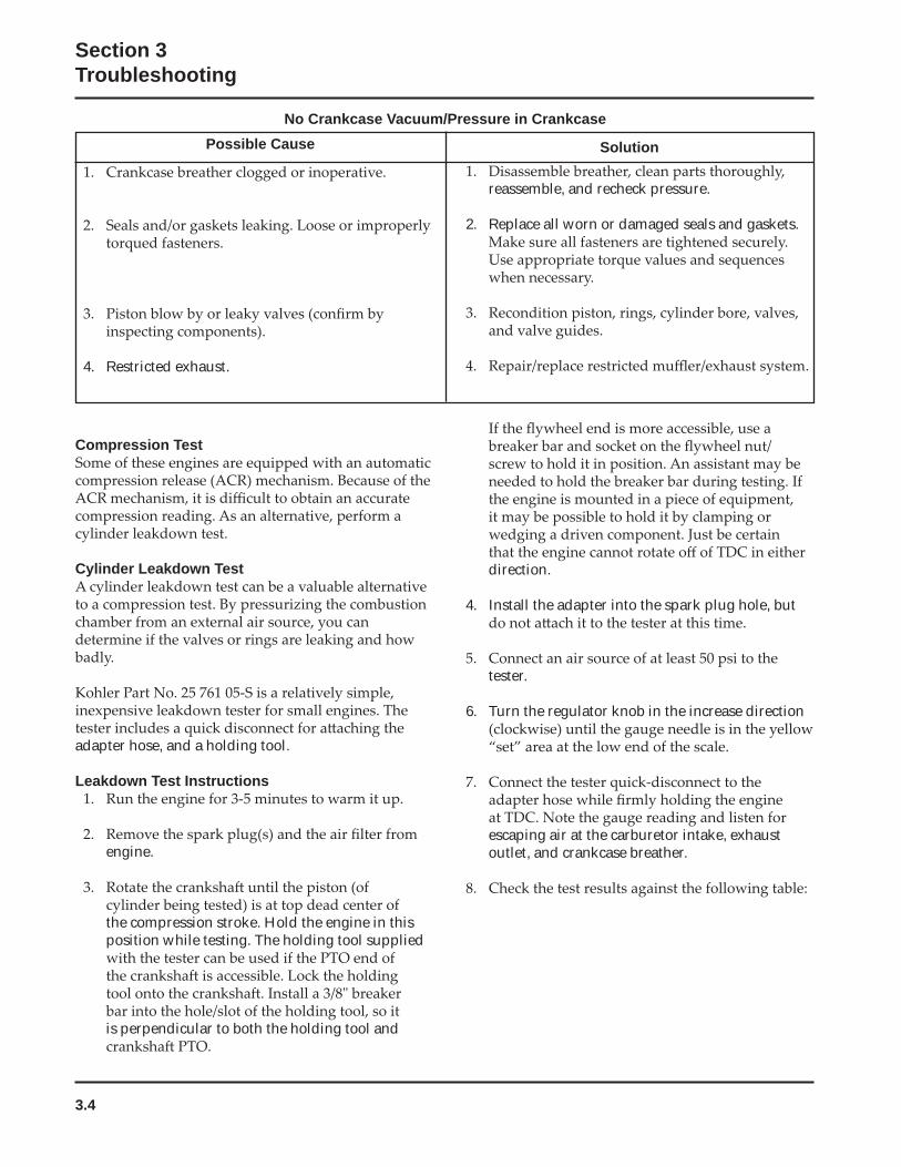
No Crankcase Vacuum/Pressure in CrankcasePossible Cause
4. Restricted exhaust.
Solution
reassemble, and recheck pressure.
2. Replace all worn or damaged seals and gaskets.
3.5
Section 3Troubleshooting
3
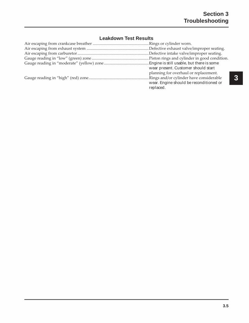
Leakdown Test Results.......................................................
...................................................................................................................................
....................................................................................................Engine is still usable, but there is some
wear present. Customer should start
...........................................................wear. Engine should be reconditioned or replaced.

3.6
Section 3Troubleshooting
4.1
Section 4Air Cleaner and Air Intake System
4
Section 4Air Cleaner and Air Intake System
Air Cleaners
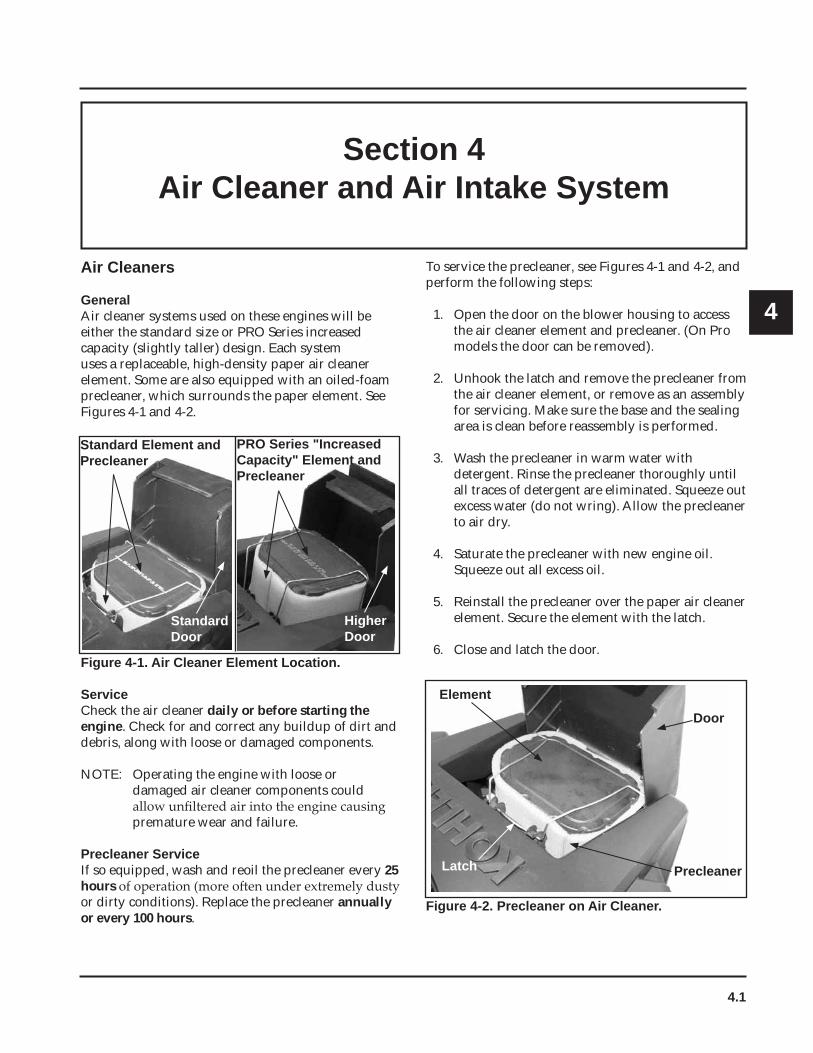
GeneralAir cleaner systems used on these engines will be either the standard size or PRO Series increased capacity (slightly taller) design. Each system uses a replaceable, high-density paper air cleaner element. Some are also equipped with an oiled-foam precleaner, which surrounds the paper element. See Figures 4-1 and 4-2.
To service the precleaner, see Figures 4-1 and 4-2, and perform the following steps:
1. Open the door on the blower housing to access the air cleaner element and precleaner. (On Pro models the door can be removed).
2. Unhook the latch and remove the precleaner from the air cleaner element, or remove as an assembly for servicing. Make sure the base and the sealing area is clean before reassembly is performed.
3. Wash the precleaner in warm water with detergent. Rinse the precleaner thoroughly until all traces of detergent are eliminated. Squeeze out excess water (do not wring). Allow the precleaner to air dry.
4. Saturate the precleaner with new engine oil. Squeeze out all excess oil.
5. Reinstall the precleaner over the paper air cleaner element. Secure the element with the latch.
6. Close and latch the door.Figure 4-1. Air Cleaner Element Location.
ServiceCheck the air cleaner daily or before starting the engine. Check for and correct any buildup of dirt and debris, along with loose or damaged components.
NOTE: Operating the engine with loose or damaged air cleaner components could
premature wear and failure.
Precleaner Service If so equipped, wash and reoil the precleaner every 25hoursor dirty conditions). Replace the precleaner annuallyor every 100 hours.
Figure 4-2. Precleaner on Air Cleaner.
Element
PRO Series "Increased Capacity" Element and Precleaner
HigherDoor
Standard Element and Precleaner
StandardDoor
Door
Element
Latch Precleaner
4.2
Section 4Air Cleaner and Air Intake System
Paper Element Service Clean the paper element every 50 hours, or replace if necessary. Replace the paper element annually or every 100 hoursextremely dusty or dirty conditions). See Figure 4-1, and follow these steps:
1. Open the door on the blower housing to access the air cleaner element. See Figures 4-1 and 4-2.
2. Unhook the latch and remove the air cleaner element and precleaner (if equipped). See Figure 4-2.
3. Remove the precleaner (if so equipped) from the paper element. Service the precleaner as described in Precleaner Service.
4. Gently tap the air cleaner element to dislodge dirt. Do not wash the paper element or use pressurized air, as this will damage the element. Replace a dirty, bent, or damaged element with a genuine Kohler element. Handle new elements carefully; do not use if the sealing surface is bent or damaged.
5. Clean the air cleaner base as required and check condition.
6. Reinstall the precleaner (if equipped), over the paper air cleaner element and install on the base. Secure with the latch.
7. Close and latch the door.
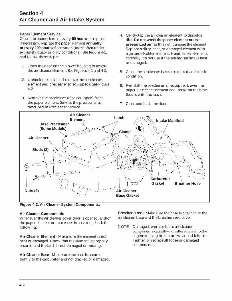
Figure 4-3. Air Cleaner System Components.
Air Cleaner ComponentsWhenever the air cleaner cover door is opened, and/or the paper element or precleaner is serviced, check the following:
Air Cleaner Element - Make sure the element is not bent or damaged. Check that the element is properly secured and the latch is not damaged or missing.
Air Cleaner Base - Make sure the base is secured tightly to the carburetor and not cracked or damaged.
Breather Hoseair cleaner base and the breather reed cover.
NOTE: Damaged, worn or loose air cleaner
engine causing premature wear and failure. Tighten or replace all loose or damaged components.
Clamp
Carburetor Gasket
Air Cleaner Base Gasket
Air Cleaner
Breather Hose
LatchIntake Manifold
Base Precleaner (Some Models)
Studs (2)
Nuts (2)
Air Cleaner Element
4.3
Section 4Air Cleaner and Air Intake System
4
Air Cleaner Base
Disassembly/ReassemblyIf the air cleaner base requires removal, proceed as follows:
1. Remove the mounting screws for the fuel pump (if equipped), and the blower housing.
2. Raise or remove the blower housing for access to the air cleaner base.
3. Remove the air cleaner components from the base. See Figure 4-3.
cleaner base onto the mounting studs.
5. Disconnect the breather hose from the air cleaner base, then remove the base and gasket.
6. Reverse procedure to reassemble components. 6.2-7.3 N·m
(55-65 in. lb.). Torque the blower housing screws to 4.0 N·m (35 in. lb.), and the two front HI-LO screws to 2.8 N·m (25 in. lb.).
Air Intake/Cooling SystemTo ensure proper cooling, make sure the grass screen,
engine are kept clean at all times.
Annually or every 100 hoursunder extremely dusty or dirty conditions), remove the blower housing and other cooling shrouds. Clean
Make sure the cooling shrouds are reinstalled.
NOTE: Operating the engine with a blocked grass
cooling shrouds removed, will cause engine damage due to overheating.

4.4
Section 4Air Cleaner and Air Intake System
5.1
Section 5Fuel System and Governor
5
Section 5Fuel System and Governor
This section covers the carbureted fuel systems used on these engines. The governor system is covered at the end of this section.
WARNING: Explosive Fuel!
Fuel System ComponentsThe typical carbureted fuel system and related components include the following:
• Fuel Tank• Fuel Lines• In-line Fuel Filter• Fuel Pump• Carburetor
OperationThe fuel from the tank is moved through the in-line
equipped with a fuel pump, the fuel tank outlet is located above the carburetor inlet allowing gravity to feed fuel to the carburetor.
drawn into the carburetor body. There, the fuel is mixed with air. This fuel-air mixture is then burned in the engine combustion chamber.
Fuel Recommendations
General RecommendationsPurchase gasoline in small quantities and store in clean, approved containers. A container with a capacity of 2 gallons or less with a pouring spout is recommended. Such a container is easier to handle and helps eliminate spillage during refueling.
season, to minimize gum deposits in your fuel system and to ensure easy starting.
• Do not add oil to the gasoline.
fuel to expand.
Fuel TypeFor best results, use only clean, fresh, unleaded gasoline with a pump sticker octane rating of 87 or higher. In countries using the Research Fuel Rating Method, it should be 90 octane minimum.
Unleaded gasoline is recommended, as it leaves less combustion chamber deposits and reduces harmful exhaust emissions. Leaded gasoline is not recommended.
Gasoline/Alcohol blendsGasohol (up to 10% ethyl alcohol, 90% unleaded gasoline by volume) is approved as a fuel for Kohler
Gasoline/Ether blends
volume) are approved as a fuel for Kohler engines.
5.2
Section 5Fuel System and Governor
Fuel Filter
annually or every 100 hours
Fuel Line
Regulations, these engines use Low Permeation
requirements. Standard fuel line may not be used.
Fuel System TestsWhen the engine starts hard, or turns over but will not start, it is possible that the problem is in the fuel
problem, perform the following tests.
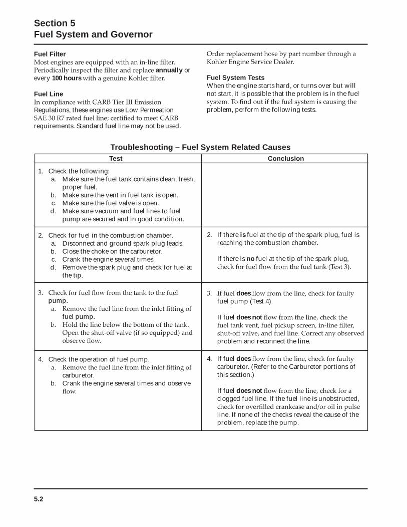
Troubleshooting – Fuel System Related CausesTest Conclusion
1. Check the following:a. Make sure the fuel tank contains clean, fresh,
proper fuel.b. Make sure the vent in fuel tank is open.c. Make sure the fuel valve is open.d. Make sure vacuum and fuel lines to fuel
pump are secured and in good condition.
2. Check for fuel in the combustion chamber.a. Disconnect and ground spark plug leads.b. Close the choke on the carburetor.c. Crank the engine several times.d. Remove the spark plug and check for fuel at
the tip.
2. If there is fuel at the tip of the spark plug, fuel is reaching the combustion chamber.
If there is no fuel at the tip of the spark plug,
pump.
fuel pump.
doesfuel pump (Test 4).
If fuel does not
problem and reconnect the line.
4. Check the operation of fuel pump.
carburetor.b. Crank the engine several times and observe
4. If fuel doescarburetor. (Refer to the Carburetor portions of this section.)
If fuel does notclogged fuel line. If the fuel line is unobstructed,
line. If none of the checks reveal the cause of the problem, replace the pump.
5.3
Section 5Fuel System and Governor
5
Replacing the Fuel PumpReplacement pumps are available through your source of supply. To replace the pulse pump follow these steps. Note the orientation of the pump before removing.
1. Disconnect the fuel lines from the inlet, outlet
the pump.
make sure opposite end is properly connected into valve cover.
pump is consistent with the removed pump. Internal damage may occur if installed incorrectly.
screws. Torque the screws to 2.3 N·m (20 in. lb.).
Carburetor
General
a self-relieving choke. These carburetors include three main circuits, which function as follows.
Float Circuit: The fuel level in the bowl is maintained
fuel pressure will push the inlet needle away from the seat, allowing more fuel to enter the bowl. When
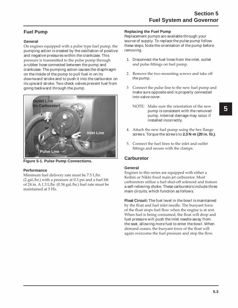
Figure 5-1. Pulse Pump Connections.
Performance
Fuel Pump
General
pumping action is created by the oscillation of positive and negative pressures within the crankcase. This
a rubber hose connected between the pump and crankcase. The pumping action causes the diaphragm on the inside of the pump to pull fuel in on its downward stroke and to push it into the carburetor on its upward stroke. Two check valves prevent fuel from going backward through the pump.
Pulse Line
Outlet Line (to Carburetor)
Inlet Line
5.4
Section 5Fuel System and Governor
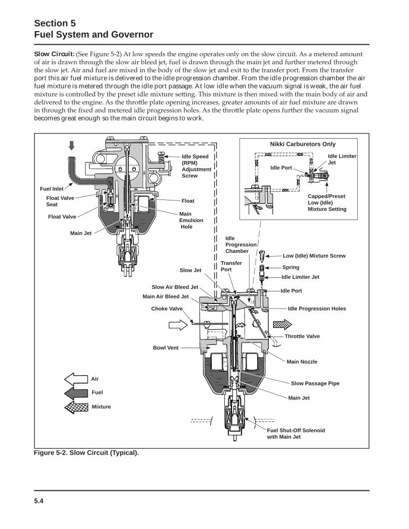
Slow Circuit:
port this air fuel mixture is delivered to the idle progression chamber. From the idle progression chamber the air fuel mixture is metered through the idle port passage. At low idle when the vacuum signal is weak, the air fuel
becomes great enough so the main circuit begins to work.
Figure 5-2. Slow Circuit (Typical).
Fuel InletFloat Valve Seat
Float Valve
Main Jet
Float
MainEmulsion Hole
Idle Speed (RPM)AdjustmentScrew
Air
Fuel
Mixture
Fuel Shut-Off Solenoid with Main Jet
Main Jet
Slow Passage Pipe
Main Nozzle
Throttle Valve
Idle Progression Holes
Idle Limiter Jet
Low (Idle) Mixture Screw
Idle Port
IdleProgressionChamber
Slow Jet
Slow Air Bleed Jet
Choke Valve
Main Air Bleed Jet
Bowl Vent
SpringTransferPort
Nikki Carburetors Only
Idle Port
Idle Limiter Jet
Capped/PresetLow (Idle) Mixture Setting
5.5
Section 5Fuel System and Governor
5
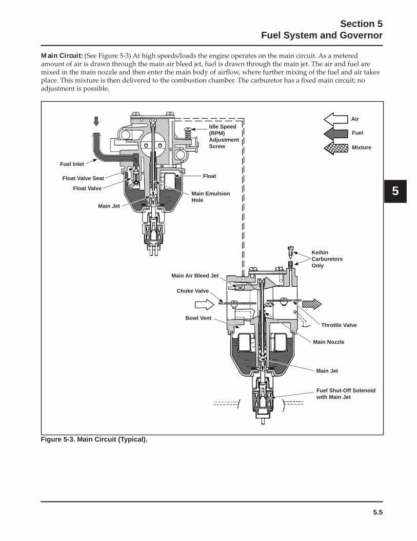
Main Circuit:
Figure 5-3. Main Circuit (Typical).
Fuel Shut-Off Solenoid with Main Jet
Main Jet
Main Nozzle
Throttle Valve
Choke Valve
Main Air Bleed Jet
Bowl Vent
Fuel Inlet
Float Valve Seat
Float Valve
Main Jet
Float
Main Emulsion Hole
Idle Speed (RPM)AdjustmentScrew
Air
Fuel
Mixture
KeihinCarburetorsOnly
5.6
Section 5Fuel System and Governor
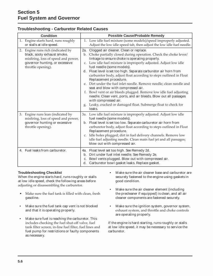
Troubleshooting - Carburetor Related CausesCondition Possible Cause/Probable Remedy
or stalls at idle speed.
black, sooty exhaust smoke,
governor hunting, or excessive
2a. Clogged air cleaner. Clean or replace.
linkage to ensure choke is operating properly.
fuel needle (some models).d. Float level is set too high. Separate carburetor air horn from
Replacement procedure.
seat and blow with compressed air.
needle. Clean vent, ports, and air bleeds. Blow out all passages with compressed air.
leaks.
governor hunting or excessive fuel needle (some models).
b. Float level is set too low. Separate carburetor air horn from
Replacement procedure.
blow out with compressed air.
4. Fuel leaks from carburetor. 4a. Float level set too high. See Remedy 2d.b. Dirt under fuel inlet needle. See Remedy 2e.c. Bowl vents plugged. Blow out with compressed air.d. Carburetor bowl gasket leaks. Replace gasket.
Troubleshooting ChecklistWhen the engine starts hard, runs roughly or stalls at low idle speed, check the following areas before
gasoline.
• Make sure the fuel tank cap vent is not blocked and that it is operating properly.
• Make sure fuel is reaching the carburetor. This
fuel pump for restrictions or faulty components as necessary.
• Make sure the air cleaner base and carburetor are securely fastened to the engine using gaskets in good condition.
• Make sure the air cleaner element (including the precleaner if equipped) is clean, and all air cleaner components are fastened securely.
• Make sure the ignition system, governor system,
are operating properly.
If the engine is hard-starting, runs roughly or stalls at low idle speed, it may be necessary to service the carburetor.
5.7
Section 5Fuel System and Governor
5
High Altitude Operation
over-rich. This can cause conditions such as black,
power, poor fuel economy, and poor or slow governor response.
correct kit number.
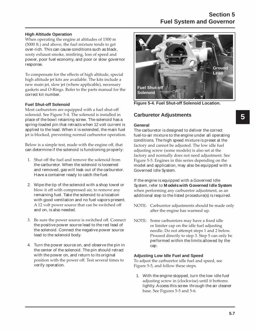
Fuel Shut-off Solenoid
place of the bowl retaining screw. The solenoid has a spring-loaded pin that retracts when 12 volt current is applied to the lead. When it is extended, the main fuel
can determine if the solenoid is functioning properly:
the carburetor. When the solenoid is loosened and removed, gas will leak out of the carburetor. Have a container ready to catch the fuel.
2. Wipe the tip of the solenoid with a shop towel or
remaining fuel. Take the solenoid to a location with good ventilation and no fuel vapors present.
and on, is also needed.
the positive power source lead to the red lead of the solenoid. Connect the negative power source lead to the solenoid body.
4. Turn the power source on, and observe the pin in the center of the solenoid. The pin should retract with the power on, and return to its original
verify operation.
Figure 5-4. Fuel Shut-off Solenoid Location.
Carburetor Adjustments
GeneralThe carburetor is designed to deliver the correct fuel-to-air mixture to the engine under all operating conditions. The high speed mixture is preset at the
model and application, may also be equipped with a Governed Idle System.
If the engine is equipped with a Governed Idle System, refer to Models with Governed Idle System
additional step to the listed procedure(s) is required.
performed within the limits allowed by the cap.
Adjusting Low Idle Fuel and Speed
1. With the engine stopped, turn the low idle fuel
lightly. Access this screw through the air cleaner
Fuel Shut-off Solenoid
GroundLead
5.8
Section 5Fuel System and Governor
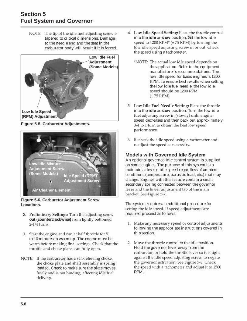
Figure 5-5. Carburetor Adjustments.
4.into the idle or slow position. Set the low idle
the speed using a tachometer.
the application. Refer to the equipment manufacturer’s recommendations. The low idle speed for basic engines is 1200
the low idle fuel needle, the low idle speed should be 1200 RPM
into the idle or slow position. Turn the low idle
speed decreases and then back out approximately
performance.
Models with Governed Idle SystemAn optional governed idle control system is supplied on some engines. The purpose of this system is to maintain a desired idle speed regardless of ambient conditions (temperature, parasitic load, etc.) that may
secondary spring connected between the governor
The system requires an additional procedure for
required proceed as follows.
following the appropriate instructions covered in this section.
Hold the governor lever away from the
RPM.
Low Idle Speed (RPM) Adjustment
Low Idle Fuel Adjustment(Some Models)
Figure 5-6. Carburetor Adjustment Screw Locations.
2.out (counterclockwise)
to 10 minutes to warm up. The engine must be
loaded. Check to make sure the plate moves
delivery.
Low Idle Mixture Adjustment Screw(Some Models) Idle Speed (RPM)
Adjustment Screw
Air Cleaner Element
tapered to critical dimensions. Damage to the needle end and the seat in the carburetor body will result if it is forced.
5.9
Section 5Fuel System and Governor
5
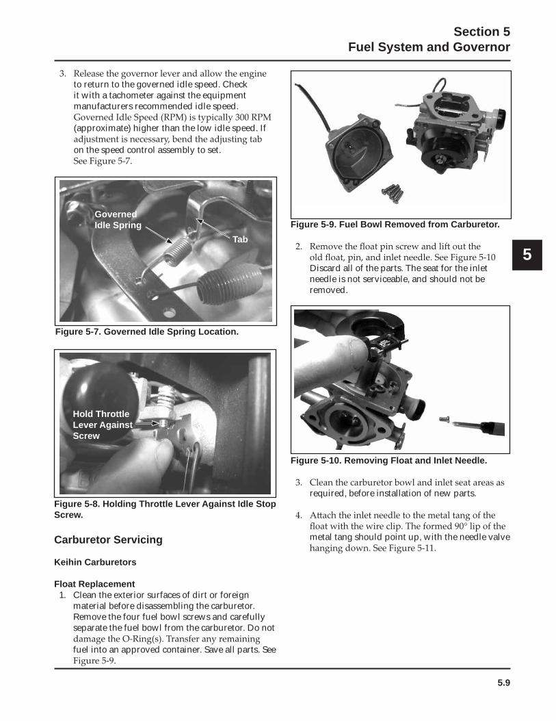
GovernedIdle Spring
Tab
Hold Throttle Lever Against Screw
Figure 5-8. Holding Throttle Lever Against Idle Stop Screw.
Carburetor Servicing
Keihin Carburetors
Float Replacement1. Clean the exterior surfaces of dirt or foreign
material before disassembling the carburetor. Remove the four fuel bowl screws and carefully separate the fuel bowl from the carburetor. Do not
fuel into an approved container. Save all parts. See
Figure 5-7. Governed Idle Spring Location.
Figure 5-9. Fuel Bowl Removed from Carburetor.
Discard all of the parts. The seat for the inlet needle is not serviceable, and should not be removed.
Figure 5-10. Removing Float and Inlet Needle.
required, before installation of new parts.
metal tang should point up, with the needle valve
to return to the governed idle speed. Check it with a tachometer against the equipment manufacturers recommended idle speed.
(approximate) higher than the low idle speed. If
on the speed control assembly to set.
5.10
Section 5Fuel System and Governor
Figure 5-14. Installing Fuel Bowl.
Disassembly/Overhaul1. Clean the exterior surfaces of dirt or foreign
material before disassembling the carburetor. Remove the four fuel bowl screws and separate the fuel bowl from the carburetor. Transfer any remaining fuel into an approved container.
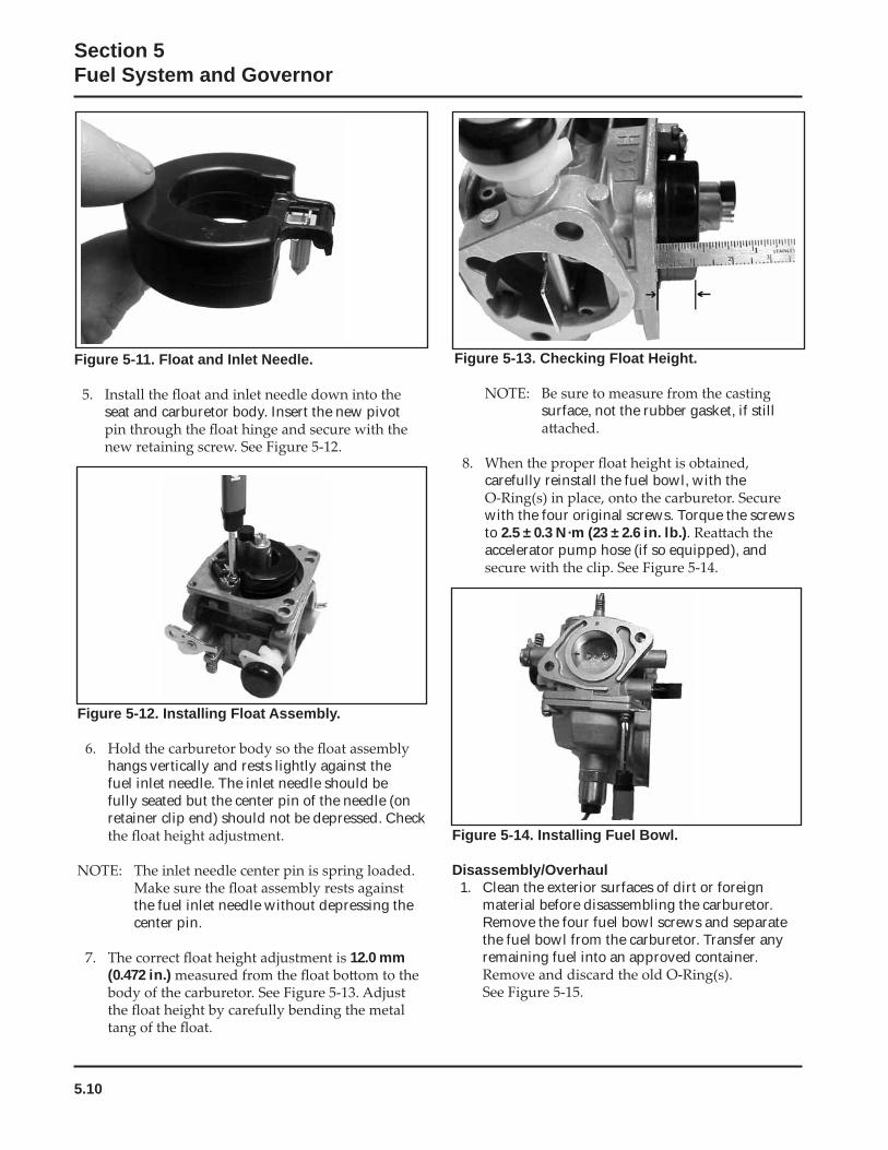
Figure 5-13. Checking Float Height.
surface, not the rubber gasket, if still
carefully reinstall the fuel bowl, with the
with the four original screws. Torque the screws to 2.5 ± 0.3 N·m (23 ± 2.6 in. lb.)accelerator pump hose (if so equipped), and
Figure 5-11. Float and Inlet Needle.
seat and carburetor body. Insert the new pivot
Figure 5-12. Installing Float Assembly.
hangs vertically and rests lightly against the fuel inlet needle. The inlet needle should be fully seated but the center pin of the needle (on retainer clip end) should not be depressed. Check
the fuel inlet needle without depressing the center pin.
12.0 mm (0.472 in.)
5.11
Section 5Fuel System and Governor
5
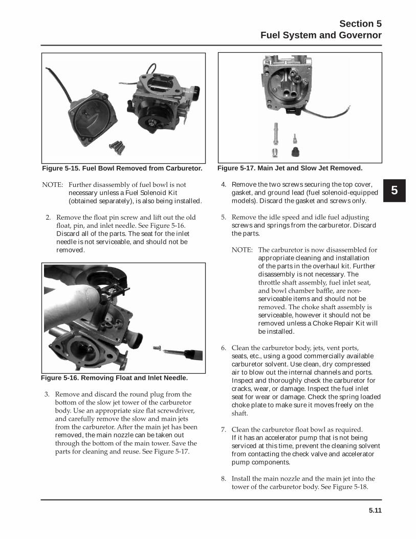
Figure 5-15. Fuel Bowl Removed from Carburetor.
necessary unless a Fuel Solenoid Kit (obtained separately), is also being installed.
Discard all of the parts. The seat for the inlet needle is not serviceable, and should not be removed.
Figure 5-16. Removing Float and Inlet Needle.
removed, the main nozzle can be taken out
Figure 5-17. Main Jet and Slow Jet Removed.
4. Remove the two screws securing the top cover, gasket, and ground lead (fuel solenoid-equipped models). Discard the gasket and screws only.
screws and springs from the carburetor. Discard the parts.
appropriate cleaning and installation of the parts in the overhaul kit. Further disassembly is not necessary. The
serviceable items and should not be
serviceable, however it should not be removed unless a Choke Repair Kit will be installed.
seats, etc., using a good commercially available carburetor solvent. Use clean, dry compressed air to blow out the internal channels and ports. Inspect and thoroughly check the carburetor for cracks, wear, or damage. Inspect the fuel inlet seat for wear or damage. Check the spring loaded choke plate to make sure it moves freely on the
If it has an accelerator pump that is not being serviced at this time, prevent the cleaning solvent from contacting the check valve and accelerator pump components.
5.12
Section 5Fuel System and Governor
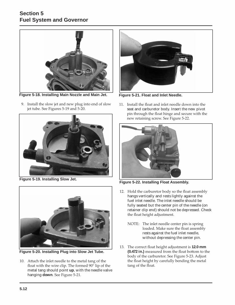
Figure 5-22. Installing Float Assembly.
hangs vertically and rests lightly against the fuel inlet needle. The inlet needle should be fully seated but the center pin of the needle (on retainer clip end) should not be depressed. Check
rests against the fuel inlet needle, without depressing the center pin.
12.0 mm (0.472 in.)
Figure 5-21. Float and Inlet Needle.
seat and carburetor body. Insert the new pivot
Figure 5-18. Installing Main Nozzle and Main Jet.
Figure 5-20. Installing Plug into Slow Jet Tube.
metal tang should point up, with the needle valve hanging down
Figure 5-19. Installing Slow Jet.
5.13
Section 5Fuel System and Governor
5
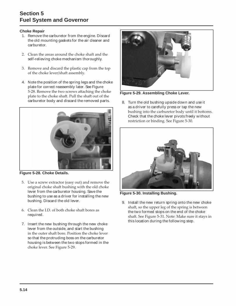
Figure 5-24. Installing Fuel Bowl O-Rings.
with the four original screws. Torque the screws to 2.5 ± 0.3 N·m (23 ± 2.6 in. lb.)
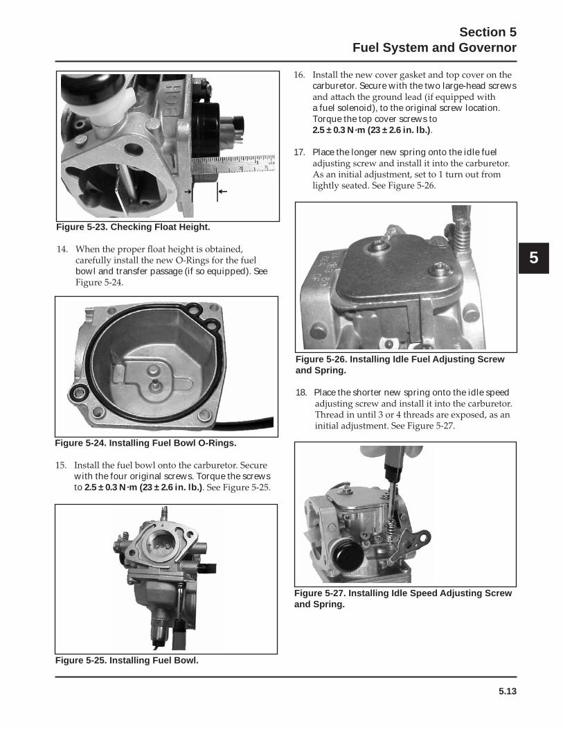
Figure 5-23. Checking Float Height.
bowl and transfer passage (if so equipped). See
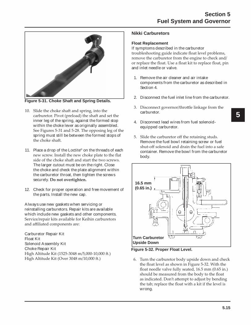
Figure 5-25. Installing Fuel Bowl.
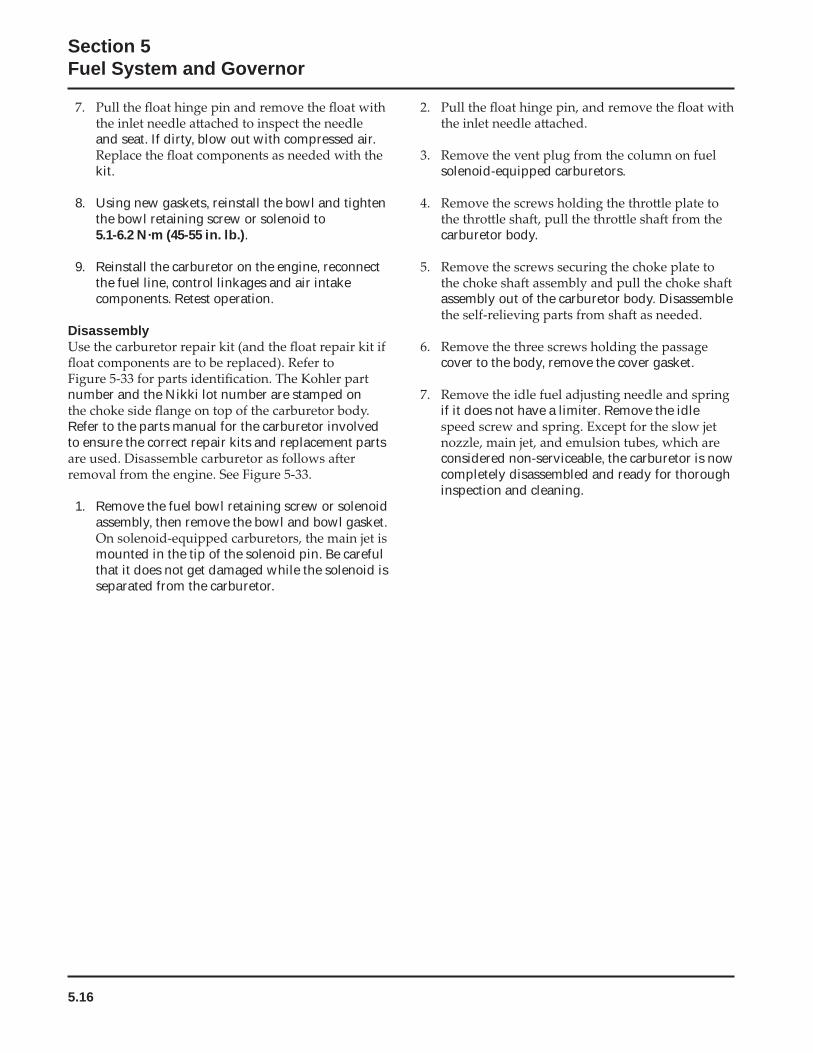
Figure 5-26. Installing Idle Fuel Adjusting Screw and Spring.
18. Place the shorter new spring onto the idle speed
carburetor. Secure with the two large-head screws
a fuel solenoid), to the original screw location. Torque the top cover screws to
2.5 ± 0.3 N·m (23 ± 2.6 in. lb.).
17. Place the longer new spring onto the idle fuel
Figure 5-27. Installing Idle Speed Adjusting Screw and Spring.
5.14
Section 5Fuel System and Governor
Figure 5-30. Installing Bushing.
9. Install the new return spring onto the new choke
the two formed stops on the end of the choke
this location during the following step.
Choke Repair1. Remove the carburetor from the engine. Discard
the old mounting gaskets for the air cleaner and carburetor.
self-relieving choke mechanism thoroughly.
4. Note the position of the spring legs and the choke plate for correct reassembly later. See Figure
carburetor body and discard the removed parts.
Figure 5-28. Choke Details.
lever from the carburetor housing. Save the bushing to use as a driver for installing the new bushing. Discard the old lever.
required.
7. Insert the new bushing through the new choke lever from the outside, and start the bushing
so that the protruding boss on the carburetor housing is between the two stops formed in the
Figure 5-29. Assembling Choke Lever.
8. Turn the old bushing upside down and use it as a driver to carefully press or tap the new
Check that the choke lever pivots freely without
5.15
Section 5Fuel System and Governor
5
Figure 5-31. Choke Shaft and Spring Details.
inner leg of the spring, against the formed stop within the choke lever as originally assembled.
spring must still be between the formed stops of
11. Place a drop of the Loctite® on the threads of each
The larger cutout must be on the right. Close the choke and check the plate alignment within the carburetor throat, then tighten the screws securely.
12. Check for proper operation and free movement of the parts. Install the new cap.
Always use new gaskets when servicing or reinstalling carburetors. Repair kits are available which include new gaskets and other components.
Carburetor Repair KitFloat KitSolenoid Assembly KitChoke Repair Kit
Nikki Carburetors
Float ReplacementIf symptoms described in the carburetor
and inlet needle or valve.
1. Remove the air cleaner and air intake components from the carburetor as described in Section 4.
2. Disconnect the fuel inlet line from the carburetor.
carburetor.
4. Disconnect lead wires from fuel solenoid-equipped carburetor.
Remove the fuel bowl retaining screw or fuel
container. Remove the bowl from the carburetor body.
Figure 5-32. Proper Float Level.
wrong.
16.5 mm(0.65 in.)
Turn Carburetor Upside Down
5.16
Section 5Fuel System and Governor
and seat. If dirty, blow out with compressed air.
kit.
8. Using new gaskets, reinstall the bowl and tighten the bowl retaining screw or solenoid to 5.1-6.2 N·m (45-55 in. lb.).
9. Reinstall the carburetor on the engine, reconnect the fuel line, control linkages and air intake components. Retest operation.
Disassembly
number and the Nikki lot number are stamped on
Refer to the parts manual for the carburetor involved to ensure the correct repair kits and replacement parts
1. Remove the fuel bowl retaining screw or solenoid assembly, then remove the bowl and bowl gasket.
mounted in the tip of the solenoid pin. Be careful that it does not get damaged while the solenoid is separated from the carburetor.
solenoid-equipped carburetors.
carburetor body.
assembly out of the carburetor body. Disassemble
cover to the body, remove the cover gasket.
if it does not have a limiter. Remove the idle
considered non-serviceable, the carburetor is now completely disassembled and ready for thorough inspection and cleaning.
5.17
Section 5Fuel System and Governor
5
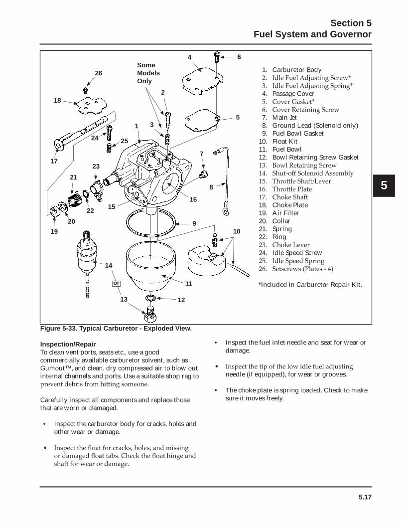
Figure 5-33. Typical Carburetor - Exploded View.
Inspection/RepairTo clean vent ports, seats etc., use a good commercially available carburetor solvent, such as Gumout™, and clean, dry compressed air to blow out internal channels and ports. Use a suitable shop rag to
Carefully inspect all components and replace those that are worn or damaged.
• Inspect the carburetor body for cracks, holes and other wear or damage.
• Inspect the fuel inlet needle and seat for wear or damage.
needle (if equipped), for wear or grooves.
• The choke plate is spring loaded. Check to make sure it moves freely.
1. Carburetor Body
4. Passage Cover
7. Main Jet8. Ground Lead (Solenoid only)9. Fuel Bowl Gasket
10. Float Kit11. Fuel Bowl12. Bowl Retaining Screw Gasket
18. Choke Plate19. Air Filter20. Collar21. Spring22. Ring
24. Idle Speed Screw
*Included in Carburetor Repair Kit.or
14
13 12
11
109
16
8
7
3
2524
1723
21
1920
22 15
1
182
5
6
26
4SomeModelsOnly
5.18
Section 5Fuel System and Governor
in the fast position, the tension of the governor
engine is operating, the governor gear assembly is rotating. The force applied by the regulating
the force applied by the regulating pin balance each other during operation, to maintain engine speed.
• When load is applied and the engine speed and governor gear speed decreases, the governor spring tension moves the governor lever to open
into the engine, increasing engine speed. As
spring tension and the force applied by the
a steady engine speed.
Adjustments
General
constant, depending on the engine application.
Always use new gaskets when servicing or reinstalling carburetors. Repair kits are available which include new gaskets and other components.
Carburetor Repair KitFloat Kit
Solenoid Assembly Kit
Reassembly ProcedureReassembly is essentially the reverse of the disassembly procedure. Use new gaskets, springs and
kit. Also use new carburetor and intake manifold
Governor
General
mechanical governor. It is designed to hold the engine speed constant under changing load conditions. The
inside the crankcase on the oil pan, and is driven
follows:
• Centrifugal force acting on the rotating governor
outward as speed increases. Governor spring tension moves them inward as speed decreases.
regulating pin to move outward.
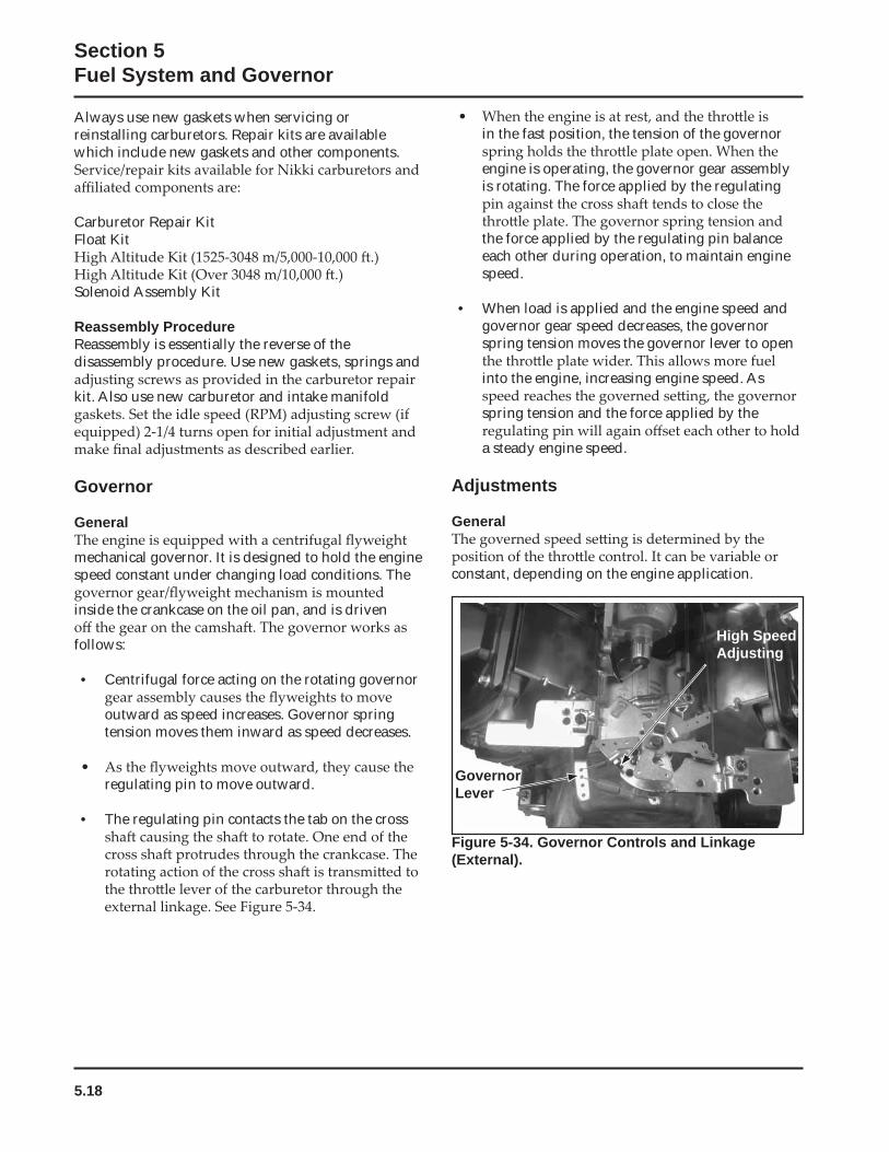
• The regulating pin contacts the tab on the cross
GovernorLever
High Speed Adjusting
Figure 5-34. Governor Controls and Linkage (External).
5.19
Section 5Fuel System and Governor
5
Initial Adjustment
carburetor.
2. Loosen the hex nut holding the governor lever to
in position.
4. Insert a nail into the hole in the end of the cross counterclockwise as far
as it will turn, then tighten the hex nut securely.
Sensitivity Adjustment
governor spring in the holes of the governor lever. If speed surging occurs with a change in engine load, the governor is set too sensitive. If a big drop in speed occurs when normal load is applied, the governor
1. To increase the sensitivity, move the spring closer to the governor lever pivot point.
2. To decrease the sensitivity, move the spring away from the governor lever pivot point.
High Speed (RPM) Adjustment (Refer to Figures 5-34 and 5-35.)
control to fast. Use a tachometer to check the RPM speed.
screw. Turn the screw counterclockwise to decrease, or clockwise to increase RPM speed. Check RPM with a tachometer.
retighten the lock nut.
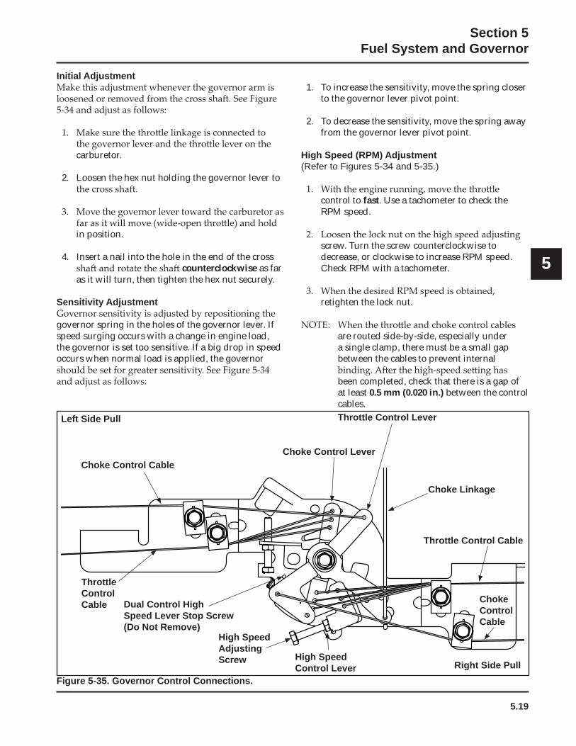
are routed side-by-side, especially under a single clamp, there must be a small gap between the cables to prevent internal
been completed, check that there is a gap of at least 0.5 mm (0.020 in.) between the control cables.
Choke Control Cable
ThrottleControlCable
Choke Control Lever
Throttle Control Lever
Choke Linkage
Throttle Control Cable
ChokeControlCable
Right Side PullHigh SpeedControl Lever
High SpeedAdjustingScrew
Dual Control HighSpeed Lever Stop Screw(Do Not Remove)
Left Side Pull
Figure 5-35. Governor Control Connections.

5.20
Section 5Fuel System and Governor
6.1
Section 6Lubrication System
6
Section 6Lubrication System
GeneralThis engine uses a combination pressure/splash lubrication system, delivering oil under pressure
surfaces. Other component areas are splash lubricated.
A pressure relief valve in the oil pump limits the maximum pressure of the system.
ServiceThe oil pan must be removed to service the oil pump or oil pickup. Refer to the appropriate procedures in Section 9, Inspection and Reconditioning.
Oil Recommendations
crankcase is extremely important; so is checking oil
Use high-quality detergent oil of API (American Petroleum Institute) Service Class SJ, or higher.Select the viscosity based on the air temperature at the
NOTE: Using other than service class SJ or higher oil, or extending oil change intervals longer than recommended can cause engine damage.
NOTE: Synthetic oils meeting the listed
performed at the recommended intervals.
operated for at least 50 hours using standard
synthetic oil.
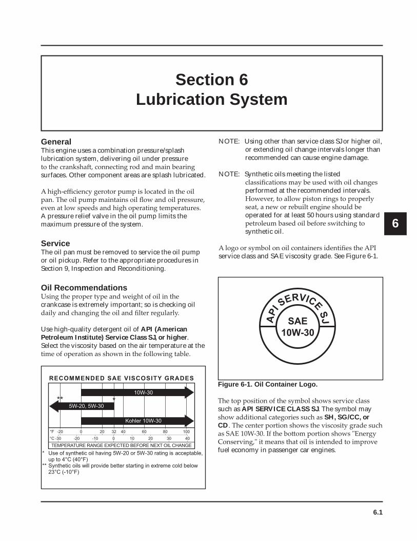
service class and SAE viscosity grade. See Figure 6-1.
Figure 6-1. Oil Container Logo.
such as API SERVICE CLASS SJ. The symbol may SH, SG/CC, or
CD
fuel economy in passenger car engines.
SAE10W-30
API
SERVICESJ
5W-20, 5W-30
RECOMMENDED SAE VISCOSITY GRADES
10W-30
Kohler 10W-30
°F -20 0 20 32 40 60 80 100
°C -30 -20 -10 0 10 20 30 40
TEMPERATURE RANGE EXPECTED BEFORE NEXT OIL CHANGE * Use of synthetic oil having 5W-20 or 5W-30 rating is acceptable,
up to 4°C (40°F)** Synthetic oils will provide better starting in extreme cold below
23°C ( -10°F)
** *
6.2
Section 6Lubrication System
mark, drain oil to reach proper level. Reinstall the
Changing Oil and Oil Filterannually or every 100
hours of operation (more frequently under severe
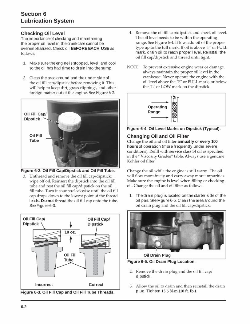
1. The drain plug is located on the starter side of the oil pan. See Figure 6-5. Clean the area around the
Checking Oil LevelThe importance of checking and maintaining the proper oil level in the crankcase cannot be overemphasized. Check oil BEFORE EACH USE as
1. Make sure the engine is stopped, level, and cool so the oil has had time to drain into the sump.
2. Clean the area around and the under side of
Oil Drain Plug
leads. Do not See Figure 6-3.
Figure 6-2. Oil Fill Cap/Dipstick and Oil Fill Tube.
Oil FillTube
Oil Fill Cap/Dipstick
Figure 6-3. Oil Fill Cap and Oil Fill Tube Threads.
10 oz.
Incorrect Correct
Figure 6-4. Oil Level Marks on Dipstick (Typical).
OperatingRange
Oil Fill Cap/Dipstick
Oil Fill Cap/Dipstick
Oil FillTube Figure 6-5. Oil Drain Plug Location.
dipstick.
plug. Tighten .
6.3
Section 6Lubrication System
6
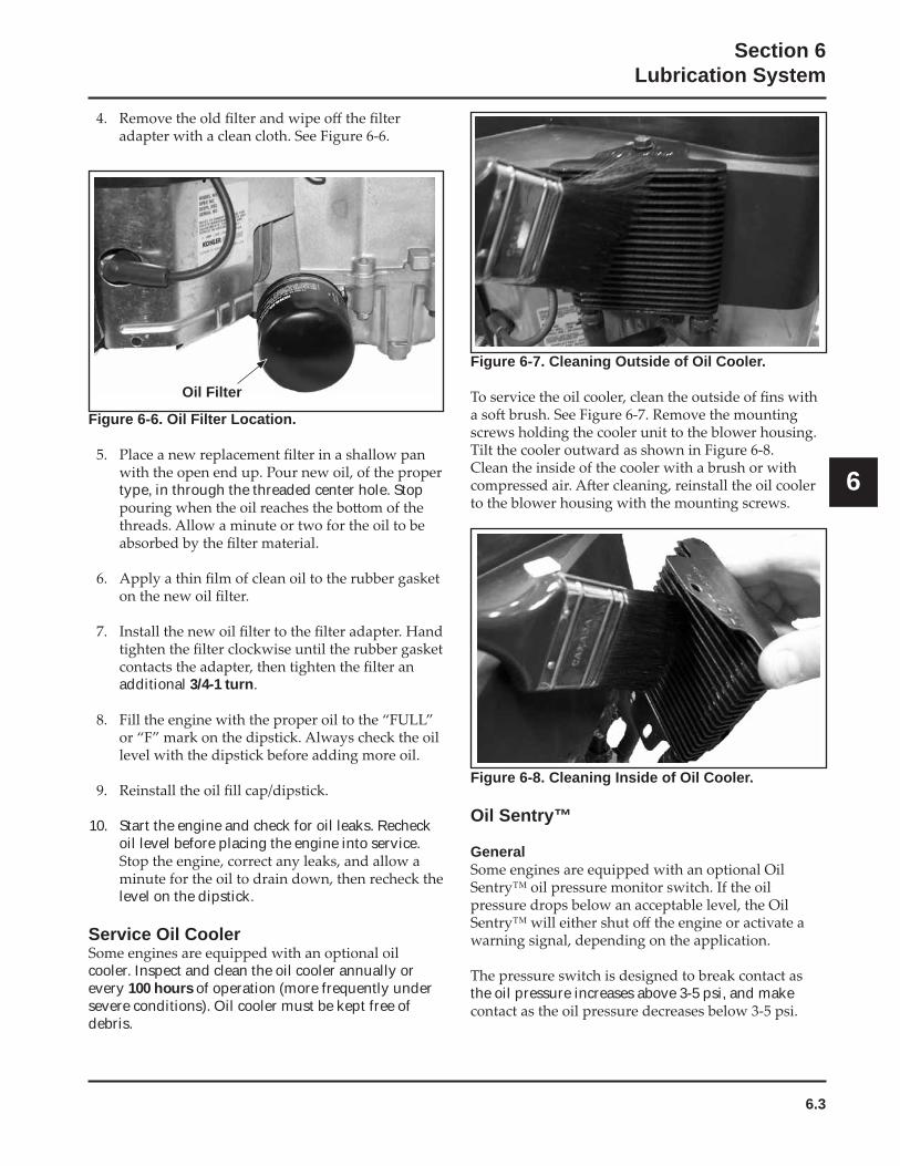
Figure 6-8. Cleaning Inside of Oil Cooler.
Oil Sentry™
General
the oil pressure increases above 3-5 psi, and make
Figure 6-6. Oil Filter Location.
type, in through the threaded center hole. Stop
additional 3/4-1 turn.
10. Start the engine and check for oil leaks. Recheck oil level before placing the engine into service.
level on the dipstick.
Service Oil Cooler
cooler. Inspect and clean the oil cooler annually or every 100 hours of operation (more frequently under severe conditions). Oil cooler must be kept free of debris.
Oil Filter
Figure 6-7. Cleaning Outside of Oil Cooler.
6.4
Section 6Lubrication System
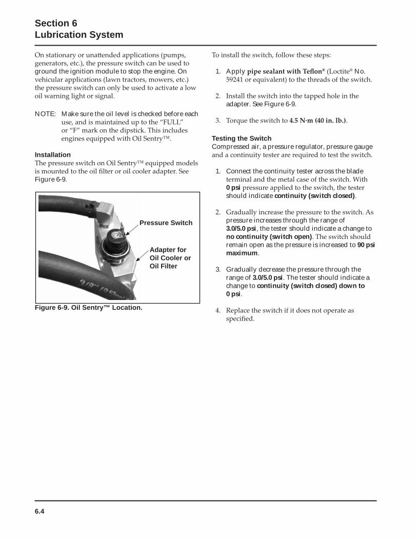
Figure 6-9. Oil Sentry™ Location.
1. Apply ® ® No.
adapter. See Figure 6-9.
.
Testing the SwitchCompressed air, a pressure regulator, pressure gauge
1. Connect the continuity tester across the blade
0 psi should indicate continuity (switch closed).
pressure increases through the range of 3.0/5.0 psi, the tester should indicate a change to no continuity (switch open)remain open as the pressure is increased to 90 psi maximum.
3. Gradually decrease the pressure through the range of 3.0/5.0 psi. The tester should indicate a change to continuity (switch closed) down to 0 psi.
Adapter forOil Cooler or Oil Filter
ground the ignition module to stop the engine. On
NOTE: Make sure the oil level is checked before each
Installation
Figure 6-9.
Pressure Switch

7.1
Section 7Electrical System and Components
7
Section 7Electrical System and Components
This section covers the operation, service, and repair of the electrical system components. Systems and components covered in this section are:
• Spark Plugs
• Electric Starter
Spark Plugs
condition.
The engine is equipped with the following spark plugs:
Type: ®
®
®
Gap:Thread Size:Reach:Hex Size:
Spark Plug Service100 hours of
gap or replace with new plugs as necessary. To service the plugs, perform the following steps:
Replace the spark plug if necessary.
plug and enter the engine, causing extensive wear and damage.
the gap to 0.76 mm (0.030 in.)
Figure 7-1. Servicing Spark Plug.
and torque to .
Inspection
the cylinder head. The deposits on the tip are an indication of the general condition of the piston rings,
photos:
Wire Gauge
GroundElectrode
Spark Plug
0.76 mm (0.030 in.) Gap
7.2
Section 7Electrical System and Components
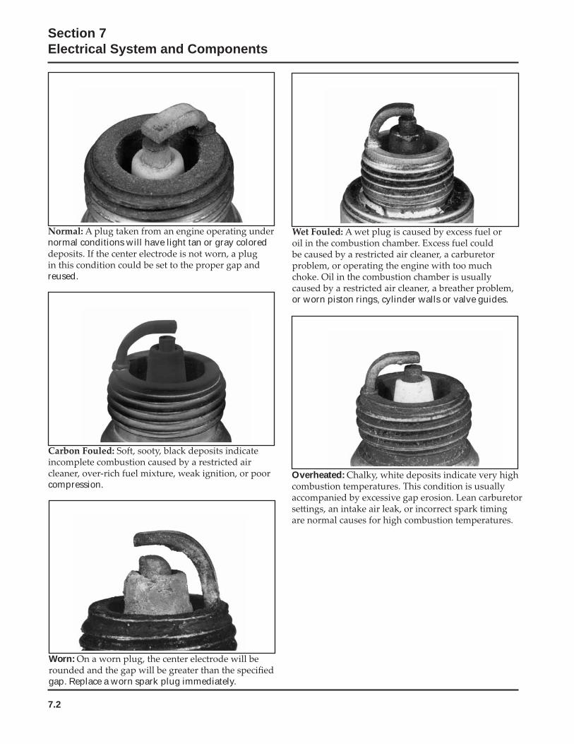
normal conditions will have light tan or gray colored
reused.
or worn piston rings, cylinder walls or valve guides.
compression.
Worn:
gap. Replace a worn spark plug immediately.
Overheated:
7.3
Section 7Electrical System and Components
7
Battery Maintenance
life.
distilled water as necessary to maintain the recommended level.
performance or early failure due to loss of electrolyte will result.
or grime on the external surfaces can cause the
rapidly when moisture is present.
Rinse thoroughly with clear water.
to enter the cells, as this will destroy the electrolyte.
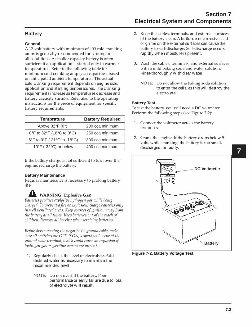
Battery Test
terminals.
discharged, or faulty.
Battery
General
amps is generally recommended for starting in
cold cranking requirement depends on engine size, application and starting temperatures. The cranking requirements increase as temperatures decrease and
Figure 7-2. Battery Voltage Test.
DC Voltmeter
Battery
Temprature Battery RequiredAbove 32°F (0°) 200 cca minimum
0°F to 32°F (18°C to 0°C) 250 cca minimum
-5°F to 0°F (-21°C to -18°C) 300 cca minimum
-10°F (-32°C) or below 400 cca minimum
7.4
Section 7Electrical System and Components
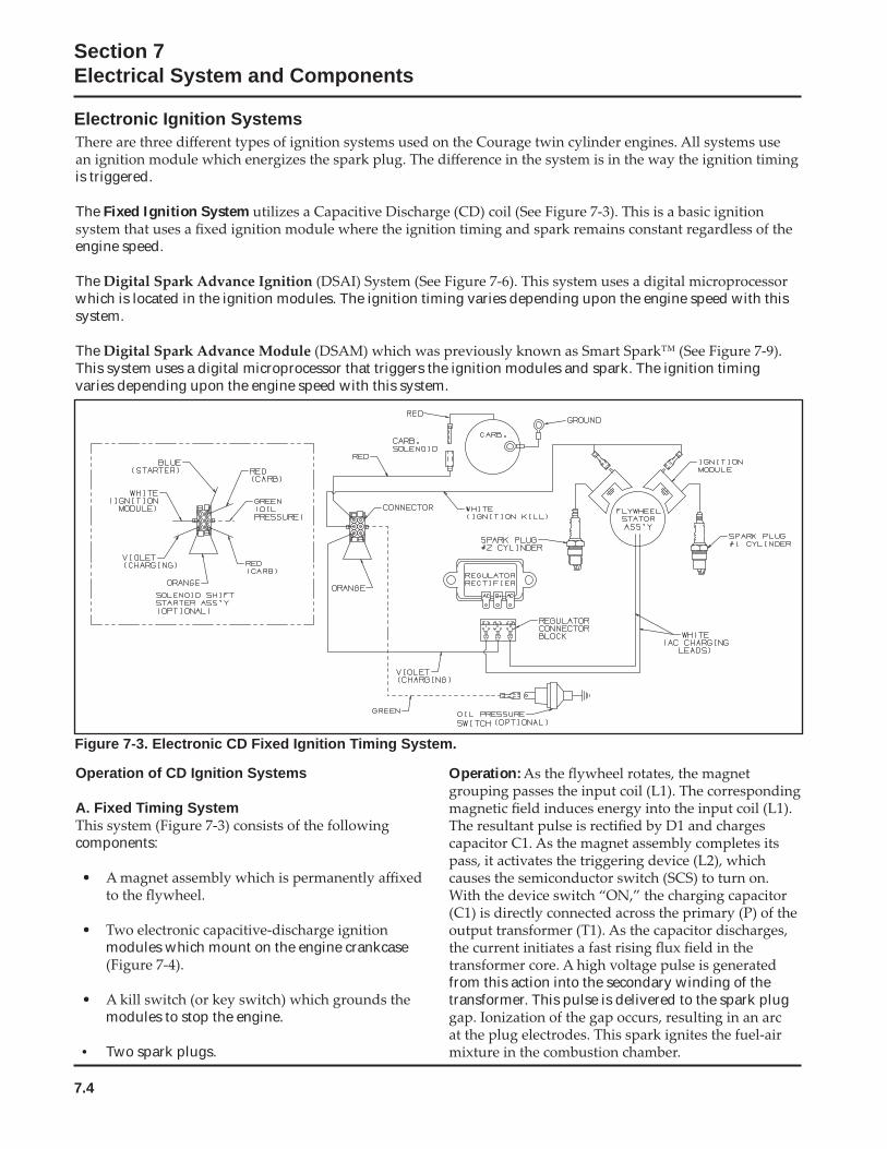
Electronic Ignition Systems
Figure 7-3. Electronic CD Fixed Ignition Timing System.
Operation of CD Ignition Systems
A. Fixed Timing System
components:
modules which mount on the engine crankcase
modules to stop the engine.
• Two spark plugs.
is triggered.
The Fixed Ignition System
engine speed.
Thewhich is located in the ignition modules. The ignition timing varies depending upon the engine speed with this system.
TheThis system uses a digital microprocessor that triggers the ignition modules and spark. The ignition timing varies depending upon the engine speed with this system.
Operation:
from this action into the secondary winding of the transformer. This pulse is delivered to the spark plug
7.5
Section 7Electrical System and Components
7
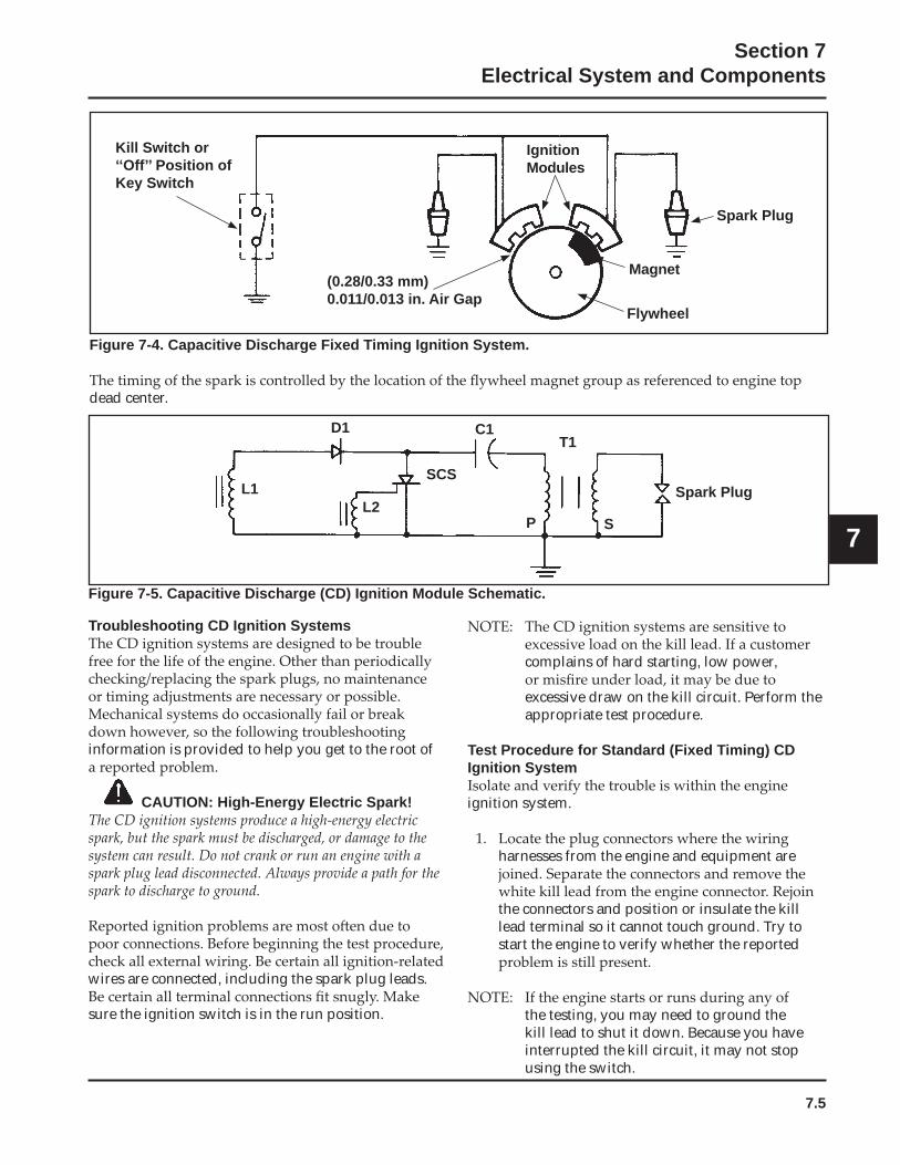
Figure 7-4. Capacitive Discharge Fixed Timing Ignition System.
dead center.
Kill Switch or ‘‘Off’’ Position of Key Switch
IgnitionModules
Spark Plug
Magnet
Flywheel
(0.28/0.33 mm)0.011/0.013 in. Air Gap
L1
D1 C1T1
P S
Spark PlugL2
SCS
Figure 7-5. Capacitive Discharge (CD) Ignition Module Schematic.
Troubleshooting CD Ignition Systems
information is provided to help you get to the root of
CAUTION: High-Energy Electric Spark!
wires are connected, including the spark plug leads.
sure the ignition switch is in the run position.
complains of hard starting, low power,
excessive draw on the kill circuit. Perform the appropriate test procedure.
Test Procedure for Standard (Fixed Timing) CD Ignition System
ignition system.
harnesses from the engine and equipment are
the connectors and position or insulate the kill lead terminal so it cannot touch ground. Try to start the engine to verify whether the reported
the testing, you may need to ground the kill lead to shut it down. Because you have interrupted the kill circuit, it may not stop using the switch.
7.6
Section 7Electrical System and Components
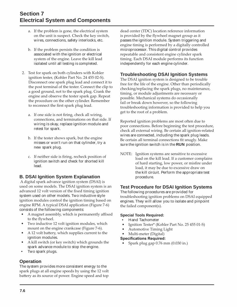
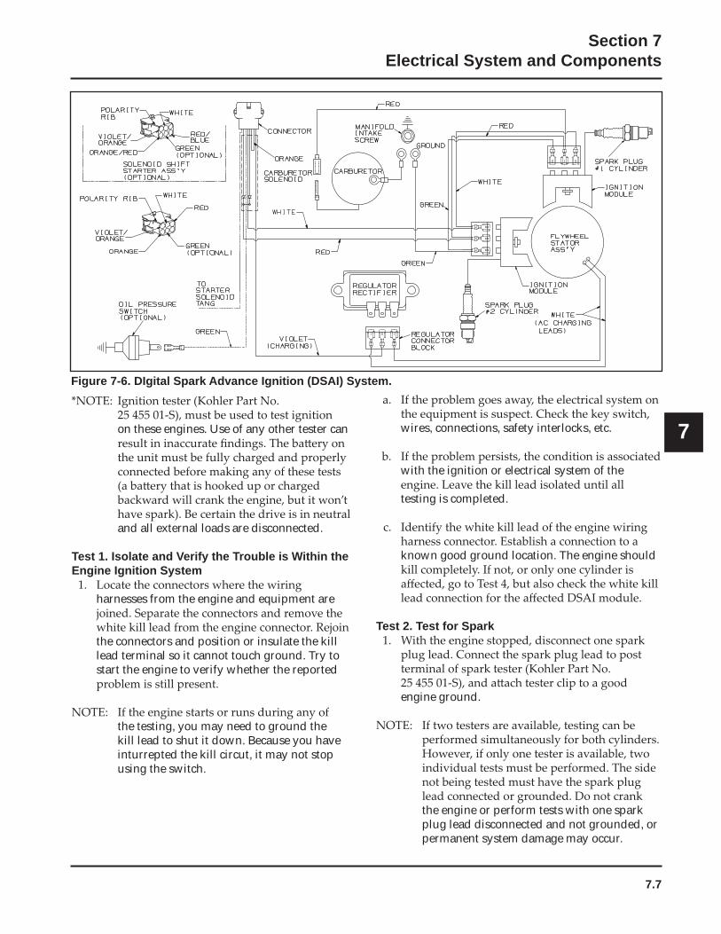
B. DSAI Ignition System Explanation
system used on other models. Two inductive style
consists of the following components:
ignition modules.
spark advance module to stop the engine.• Two spark plugs.
OperationThe system provides more consistent energy to the
passes the ignition module. System triggering and
microprocessor. This digital control provides
independently for each engine cylinder.
Troubleshooting DSAI Ignition Systems
wires are connected, including the spark plug leads.
sure the ignition switch is in the RUN position.
the kill circuit. Perform the appropriate test procedure.
Test Procedure for DSAI Ignition Systems The following procedures are provided for
engines. They will allow you to isolate and pinpoint
Special Tools Required:• Hand Tachometer
wires, connections, safety interlocks, etc.
associated with the ignition or electrical
isolated until all testing is completed.
wiring is okay, replace ignition module and retest for spark.
misses or won’t run on that cylinder, try a new spark plug.
ignition switch and check for shorted kill lead.
7.7
Section 7Electrical System and Components
7on these engines. Use of any other tester can
and all external loads are disconnected.
Test 1. Isolate and Verify the Trouble is Within the Engine Ignition System
harnesses from the engine and equipment are
the connectors and position or insulate the kill lead terminal so it cannot touch ground. Try to start the engine to verify whether the reported
the testing, you may need to ground the kill lead to shut it down. Because you have inturrepted the kill circut, it may not stop using the switch.
wires, connections, safety interlocks, etc.
with the ignition or electrical system of the
testing is completed.
known good ground location. The engine should
Test 2. Test for Spark
engine ground.
the engine or perform tests with one spark plug lead disconnected and not grounded, or permanent system damage may occur.
Figure 7-6. DIgital Spark Advance Ignition (DSAI) System.
7.8
Section 7Electrical System and Components
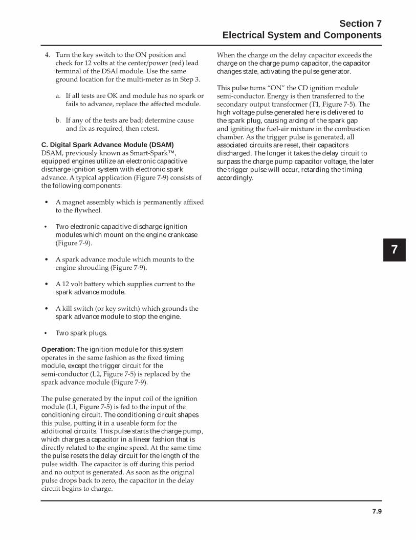
Figure 7-8. Check for timing advance.
Test 4. Test the Ignition Modules and Connections
that connections are oriented properly on terminals of modules.
with aerosol electrical contact cleaner to remove any old dielectric compound, dark residue, dirt,
from the spark plugs.
known good ground location on the engine.
install new spark plugs gapped at
Test 3. Check for Timing Advance
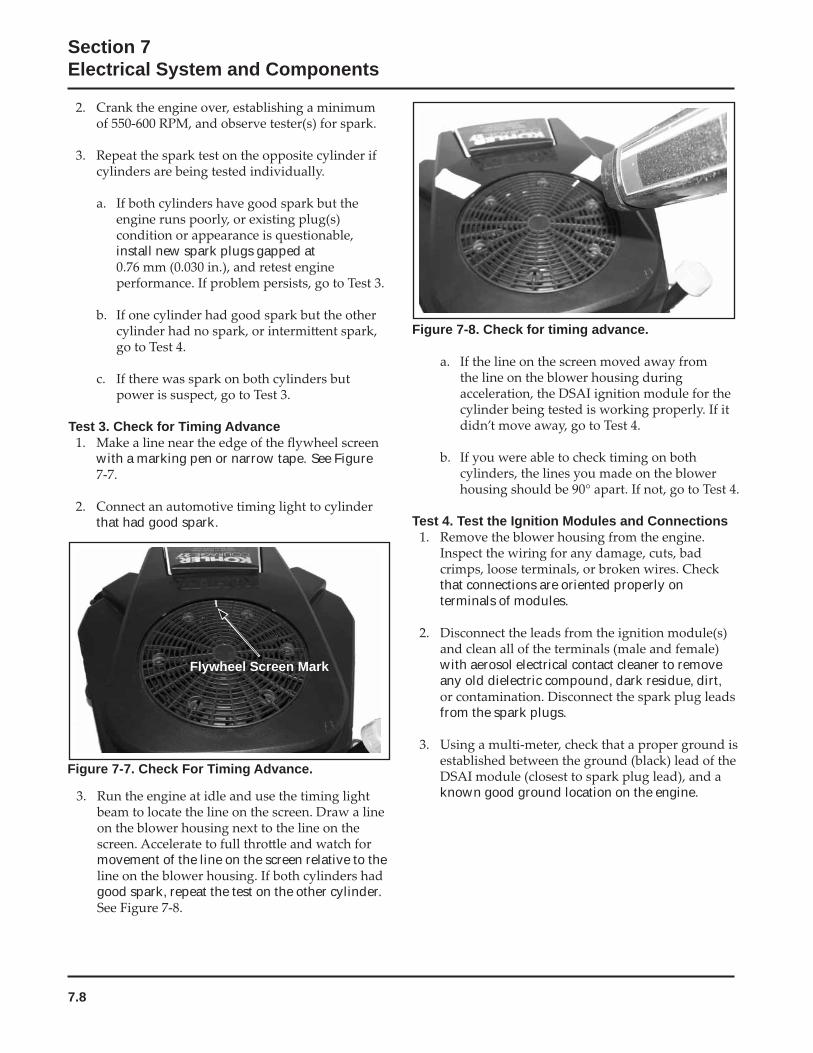
with a marking pen or narrow tape. See Figure
that had good spark.
Figure 7-7. Check For Timing Advance.
movement of the line on the screen relative to the
good spark, repeat the test on the other cylinder.
Flywheel Screen Mark
7.9
Section 7Electrical System and Components
7
C. Digital Spark Advance Module (DSAM)™,
equipped engines utilize an electronic capacitive discharge ignition system with electronic spark
the following components:
• Two electronic capacitive discharge ignition modules which mount on the engine crankcase
spark advance module.
spark advance module to stop the engine.
• Two spark plugs.
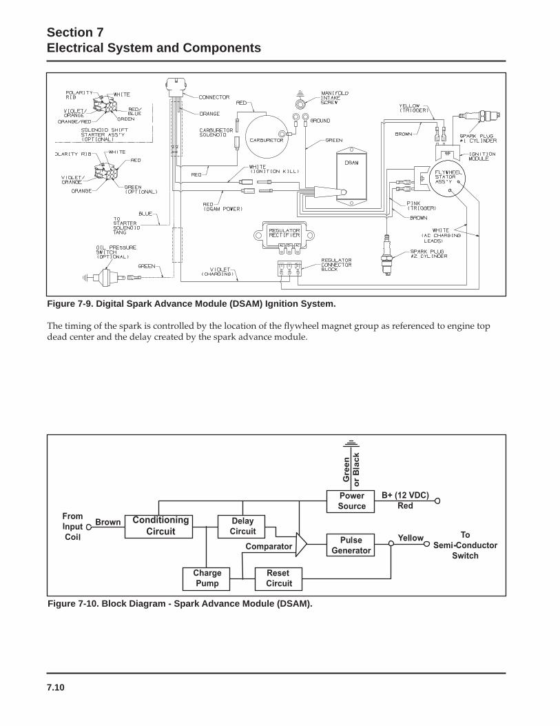
Operation: The ignition module for this system
module, except the trigger circuit for the
conditioning circuit. The conditioning circuit shapes
additional circuits. This pulse starts the charge pump, which charges a capacitor in a linear fashion that is
the pulse resets the delay circuit for the length of the
charge on the charge pump capacitor, the capacitor changes state, activating the pulse generator.
high voltage pulse generated here is delivered to the spark plug, causing arcing of the spark gap
associated circuits are reset, their capacitors discharged. The longer it takes the delay circuit to surpass the charge pump capacitor voltage, the later the trigger pulse will occur, retarding the timing accordingly.
7.10
Section 7Electrical System and Components
Figure 7-9. Digital Spark Advance Module (DSAM) Ignition System.
Figure 7-10. Block Diagram - Spark Advance Module (DSAM).
7.11
Section 7Electrical System and Components
7
Troubleshooting CD Ignition Systems
information is provided to help you get to the root of
CAUTION: High-Energy Electric Spark!
wires are connected, including the spark plug leads.
sure the ignition switch is in the RUN position.
complains of hard starting, low power,
excessive draw on the kill circuit. Perform the appropriate test procedure.
Test Procedure for DSAM Ignition Systems The following procedures are provided for
™ equipped engines, to allow
Special Tools Required:• Hand Tachometer
on these engines. Use of any other tester can
is in neutral and all external loads are disconnected.
Test 1. Isolate and Verify the Trouble is Within the Engine Ignition System.
harnesses from the engine and equipment are
the connectors and position or insulate the white kill lead terminal so it cannot touch ground. Try starting the engine to verify whether the reported
the testing, you may need to ground the kill lead to shut it down. Because you have interrupted the kill circuit, it may not stop using the switch.
wires, connections, safety interlocks, etc.
associated with the ignition or electrical
isolated until all testing is completed.
Test 2. Test for Spark.
engine ground.
the engine or perform tests with one spark plug lead disconnected and not grounded or permanent system damage may occur.
7.12
Section 7Electrical System and Components
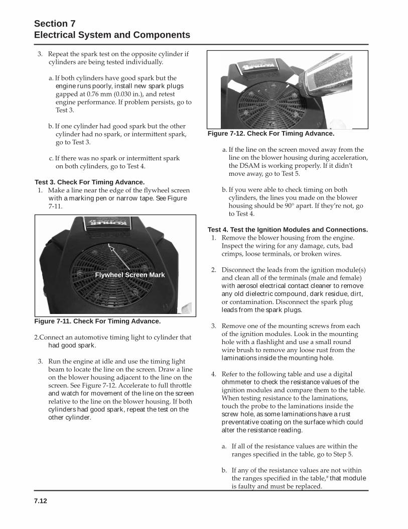
Figure 7-12. Check For Timing Advance.
Test 4. Test the Ignition Modules and Connections.
with aerosol electrical contact cleaner to remove any old dielectric compound, dark residue, dirt,
leads from the spark plugs.
laminations inside the mounting hole.
ohmmeter to check the resistance values of the
screw hole, as some laminations have a rust preventative coating on the surface which could alter the resistance reading.
# that module
engine runs poorly, install new spark plugs
Test 3. Check For Timing Advance.
with a marking pen or narrow tape. See Figure
Figure 7-11. Check For Timing Advance.
had good spark.
and watch for movement of the line on the screen
cylinders had good spark, repeat the test on the other cylinder.
Flywheel Screen Mark
7.13
Section 7Electrical System and Components
7
#
run.
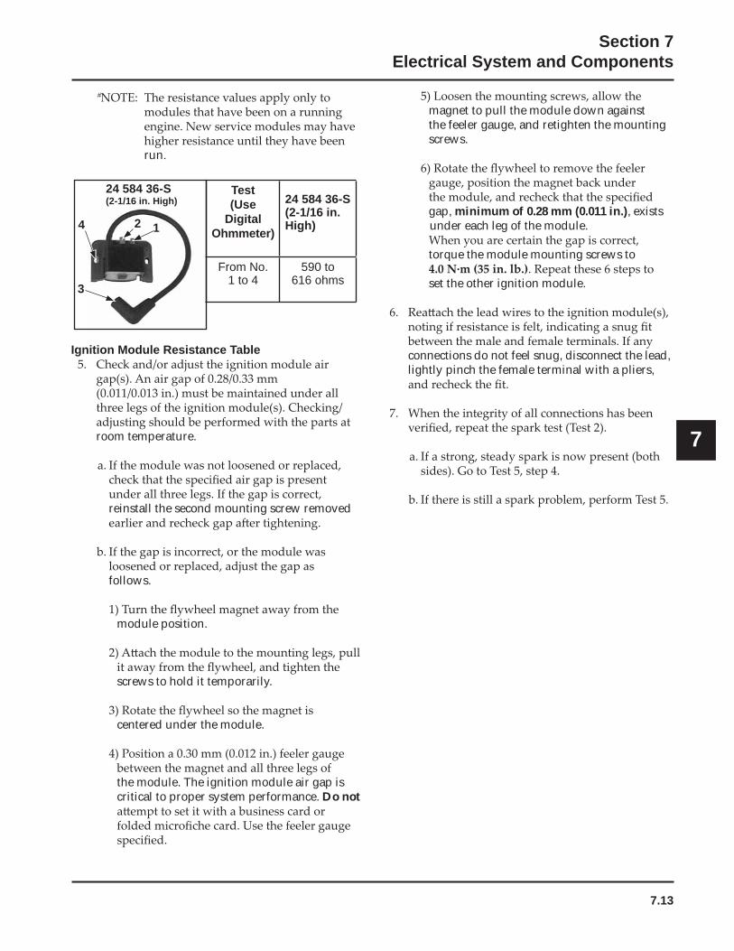
4 2 1
3
24 584 36-S(2-1/16 in. High)
Test (Use
DigitalOhmmeter)
24 584 36-S(2-1/16 in. High)
From No.1 to 4
590 to 616 ohms
Ignition Module Resistance Table
room temperature.
reinstall the second mounting screw removed
follows.
module position.
screws to hold it temporarily.
centered under the module.
the module. The ignition module air gap is critical to proper system performance. Do not
magnet to pull the module down against the feeler gauge, and retighten the mounting screws.
gap, minimum of 0.28 mm (0.011 in.), exists under each leg of the module.
torque the module mounting screws to
set the other ignition module.
connections do not feel snug, disconnect the lead, lightly pinch the female terminal with a pliers,
7.14
Section 7Electrical System and Components
™).
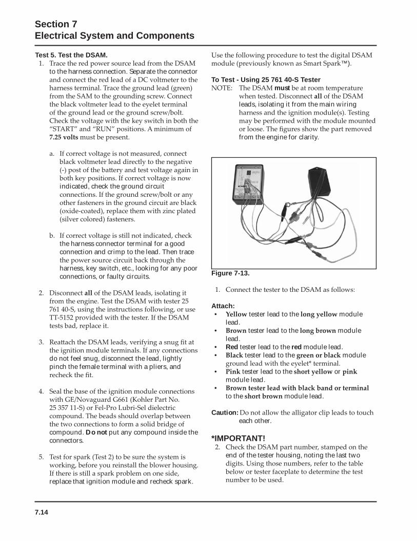
To Test - Using 25 761 40-S Testermust
leads, isolating it from the main wiring
from the engine for clarity.
Figure 7-13.
Attach:• tester lead to the module
lead.• tester lead to the module
lead.• Red tester lead to the red module lead.• tester lead to the module
• tester lead to the or module lead.
•to the module lead.
Caution:each other.
*IMPORTANT!
end of the tester housing, noting the last two
Test 5. Test the DSAM.
to the harness connection. Separate the connector
indicated, check the ground circuit
the harness connector terminal for a good connection and crimp to the lead. Then trace
harness, key switch, etc., looking for any poor connections, or faulty circuits.
do not feel snug, disconnect the lead, lightly pinch the female terminal with a pliers, and
compound. Do not put any compound inside the connectors.
replace that ignition module and recheck spark.
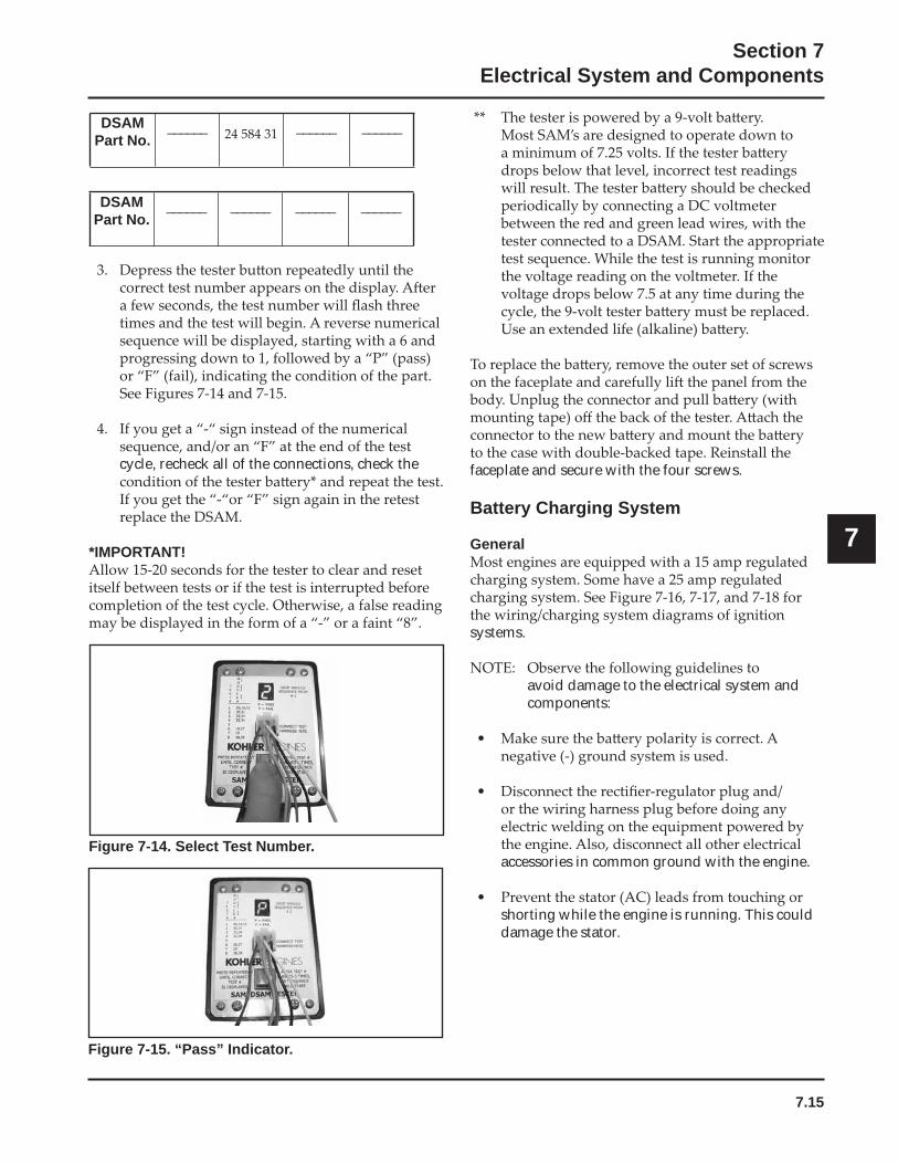
7.15
Section 7Electrical System and Components
7
DSAMPart No.
______ ______ ______
DSAMPart No.
______ ______ ______ ______
cycle, recheck all of the connections, check the
*IMPORTANT!
Figure 7-14. Select Test Number.
faceplate and secure with the four screws.
Battery Charging System
General
systems.
avoid damage to the electrical system and components:
accessories in common ground with the engine.
shorting while the engine is running. This could damage the stator.
Figure 7-15. “Pass” Indicator.
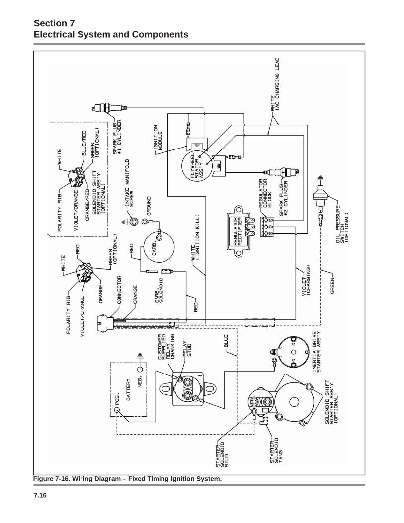
7.16
Section 7Electrical System and Components
Figure 7-16. Wiring Diagram – Fixed Timing Ignition System.
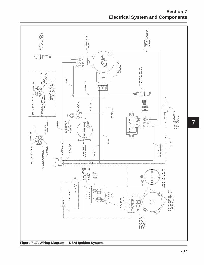
7.17
Section 7Electrical System and Components
7
Figure 7-17. Wiring Diagram – DSAI Ignition System.
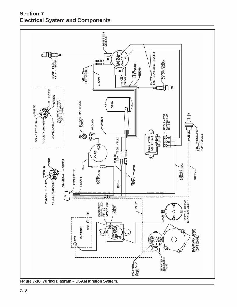
7.18
Section 7Electrical System and Components
Figure 7-18. Wiring Diagram – DSAM Ignition System.
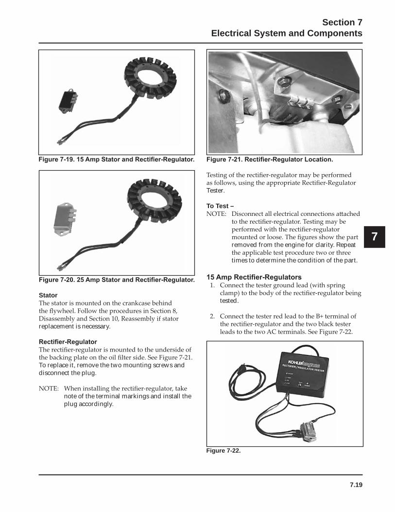
7.19
Section 7Electrical System and Components
7
Stator
replacement is necessary.
To replace it, remove the two mounting screws and disconnect the plug.
note of the terminal markings and install the plug accordingly.
Tester.
To Test –
removed from the engine for clarity. Repeat
times to determine the condition of the part.
tested.
Figure 7-22.
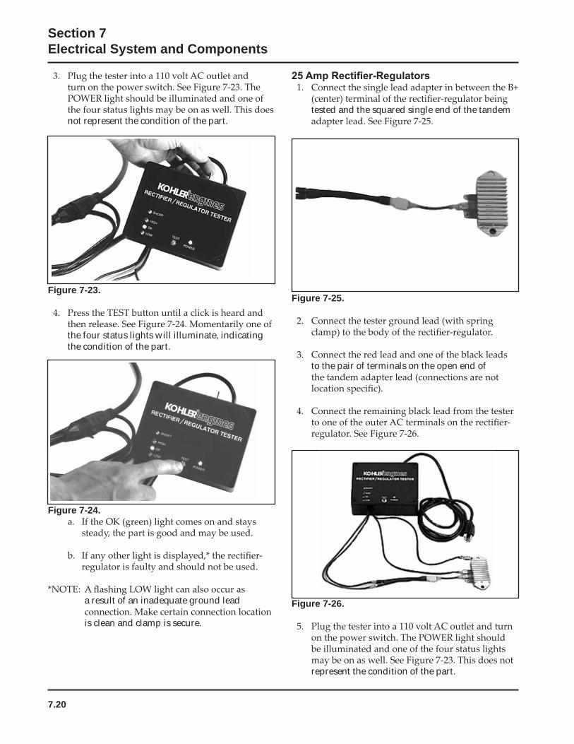
7.20
Section 7Electrical System and Components
Figure 7-26.
represent the condition of the part.
not represent the condition of the part.
Figure 7-24.
a result of an inadequate ground lead
is clean and clamp is secure.
Figure 7-23.
the four status lights will illuminate, indicating the condition of the part.
tested and the squared single end of the tandem
Figure 7-25.
to the pair of terminals on the open end of
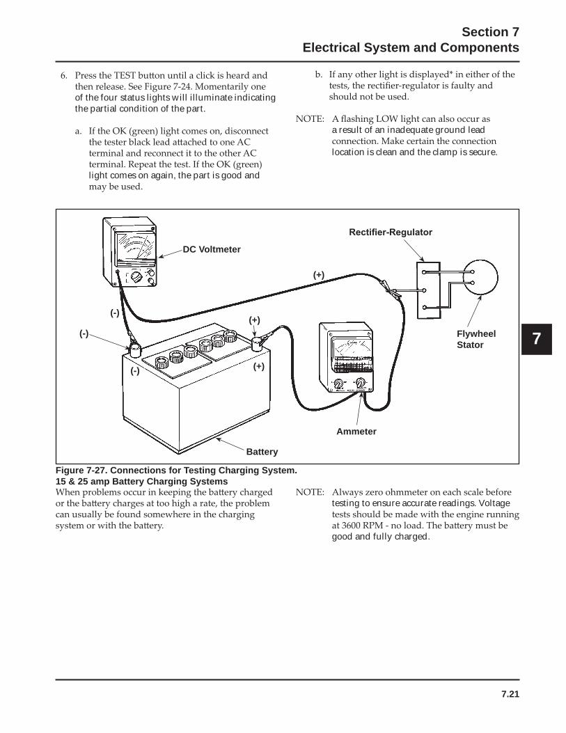
7.21
Section 7Electrical System and Components
7
a result of an inadequate ground lead
location is clean and the clamp is secure.
Figure 7-27. Connections for Testing Charging System.15 & 25 amp Battery Charging Systems
DC Voltmeter
FlywheelStator
Ammeter
Battery
(-)(+)
testing to ensure accurate readings. Voltage
good and fully charged.
of the four status lights will illuminate indicating the partial condition of the part.
light comes on again, the part is good and
(-) (+)
(-)
(+)
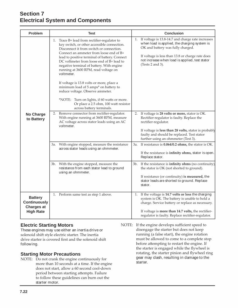
7.22
Section 7Electrical System and Components
Electric Starting MotorsThese engines may use either an inertia drive or
following.
Starting Motor Precautions
starter motor.
Problem Test Conclusion
voltmeter.
when load is applied, the charging system is
not increase when load is applied, test stator
voltmeter.
No Chargeto Battery
across stator leads using an ohmmeter. stator is open.
Replace stator.
resistance from each stator lead to ground using an ohmmeter.
the stator leads are shorted to ground. Replace stator.
the charging Battery
ContinuouslyCharges atHigh Rate
gear may clash, resulting in damage to the starter.
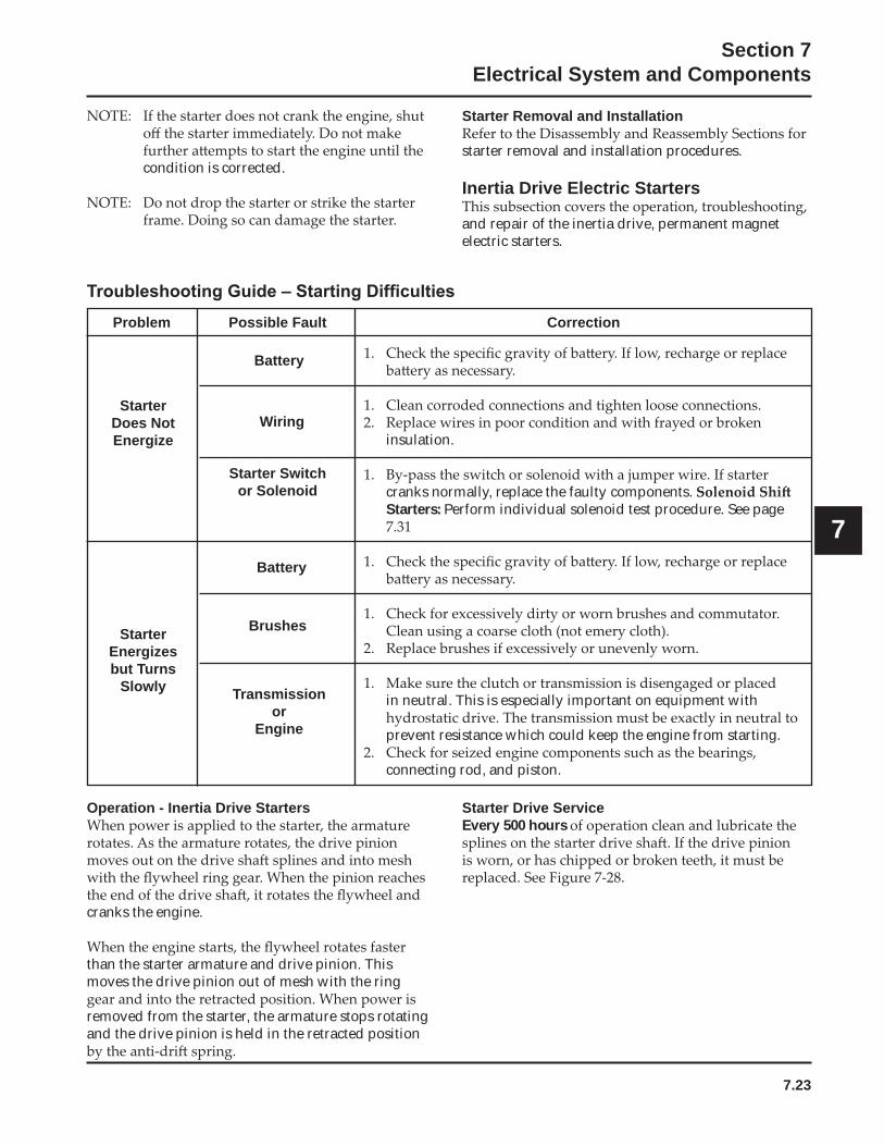
7.23
Section 7Electrical System and Components
7
condition is corrected.
Problem Possible Fault Correction
insulation.
cranks normally, replace the faulty components. Starters: Perform individual solenoid test procedure. See page
in neutral. This is especially important on equipment with
prevent resistance which could keep the engine from starting.
connecting rod, and piston.
StarterDoes NotEnergize
StarterEnergizesbut Turns
Slowly
Battery
Wiring
Starter Switchor Solenoid
Brushes
Transmissionor
Engine
Battery
Starter Removal and Installation
starter removal and installation procedures.
Inertia Drive Electric Starters
and repair of the inertia drive, permanent magnet electric starters.
Operation - Inertia Drive Starters
cranks the engine.
than the starter armature and drive pinion. This moves the drive pinion out of mesh with the ring
removed from the starter, the armature stops rotating and the drive pinion is held in the retracted position
Starter Drive ServiceEvery 500 hours
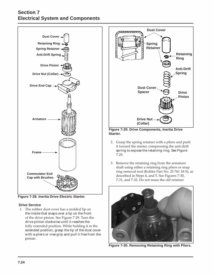
7.24
Section 7Electrical System and Components
Dust Cover
RetainingRing
Anti-DriftSpring
DrivePinion
Drive Nut(Collar)
Dust Cover Spacer
SpringRetainer
Figure 7-29. Drive Components, Inertia Drive Starter.
spring to expose the retaining ring. See Figure
Figure 7-28. Inertia Drive Electric Starter.
Drive Service
the inside that snaps over a lip on the front
drive pinion clockwise until it reaches the
extended position, grasp the tip of the dust cover with a pliers or vise grip and pull it free from the pinion.
Dust Cover
Drive Nut (Collar)
Retaining Ring
Anti-Drift Spring
Drive Pinion
Spring Retainer
Frame
Drive End Cap
Armature
Commutator End Cap with Brushes
Figure 7-30. Removing Retaining Ring with Pliers.
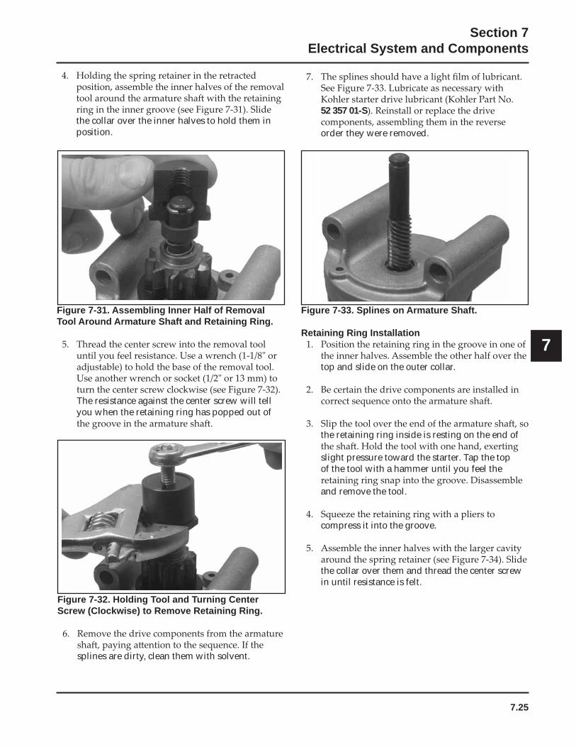
7.25
Section 7Electrical System and Components
7
Figure 7-31. Assembling Inner Half of Removal Tool Around Armature Shaft and Retaining Ring.
The resistance against the center screw will tell you when the retaining ring has popped out of
Figure 7-32. Holding Tool and Turning Center Screw (Clockwise) to Remove Retaining Ring.
splines are dirty, clean them with solvent.
the collar over the inner halves to hold them in position.
52 357 01-S
order they were removed.
Figure 7-33. Splines on Armature Shaft.
Retaining Ring Installation
top and slide on the outer collar.
the retaining ring inside is resting on the end of
slight pressure toward the starter. Tap the top of the tool with a hammer until you feel the
and remove the tool.
compress it into the groove.
the collar over them and thread the center screw in until resistance is felt.
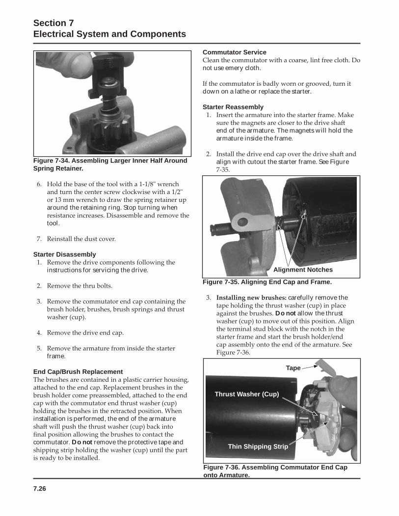
7.26
Section 7Electrical System and Components
Figure 7-34. Assembling Larger Inner Half Around Spring Retainer.
around the retaining ring. Stop turning when
tool.
Starter Disassembly
instructions for servicing the drive.
frame.
End Cap/Brush Replacement
installation is performed, the end of the armature
commutator. Do not remove the protective tape and
Figure 7-35. Aligning End Cap and Frame.
carefully remove the
Do not allow the thrust
Commutator Service
not use emery cloth.
down on a lathe or replace the starter.
Starter Reassembly
end of the armature. The magnets will hold the armature inside the frame.
align with cutout the starter frame. See Figure
Alignment Notches
Figure 7-36. Assembling Commutator End Cap onto Armature.
Tape
Thrust Washer (Cup)
Thin Shipping Strip
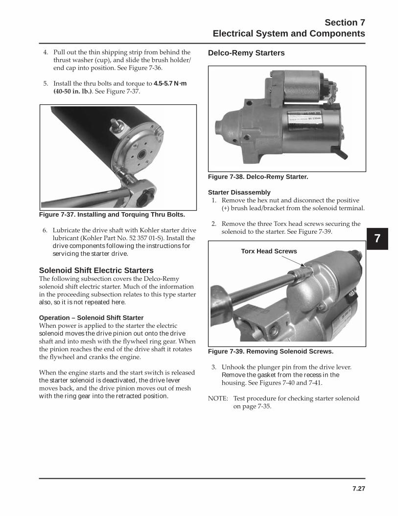
7.27
Section 7Electrical System and Components
7
4.5-5.7 N·m
Delco-Remy Starters
Figure 7-37. Installing and Torquing Thru Bolts.
drive components following the instructions for servicing the starter drive.
Solenoid Shift Electric Starters
also, so it is not repeated here.
Operation – Solenoid Shift Starter
solenoid moves the drive pinion out onto the drive
the starter solenoid is deactivated, the drive lever
with the ring gear into the retracted position.
Figure 7-38. Delco-Remy Starter.
Starter Disassembly
Torx Head Screws
Figure 7-39. Removing Solenoid Screws.
Remove the gasket from the recess in the
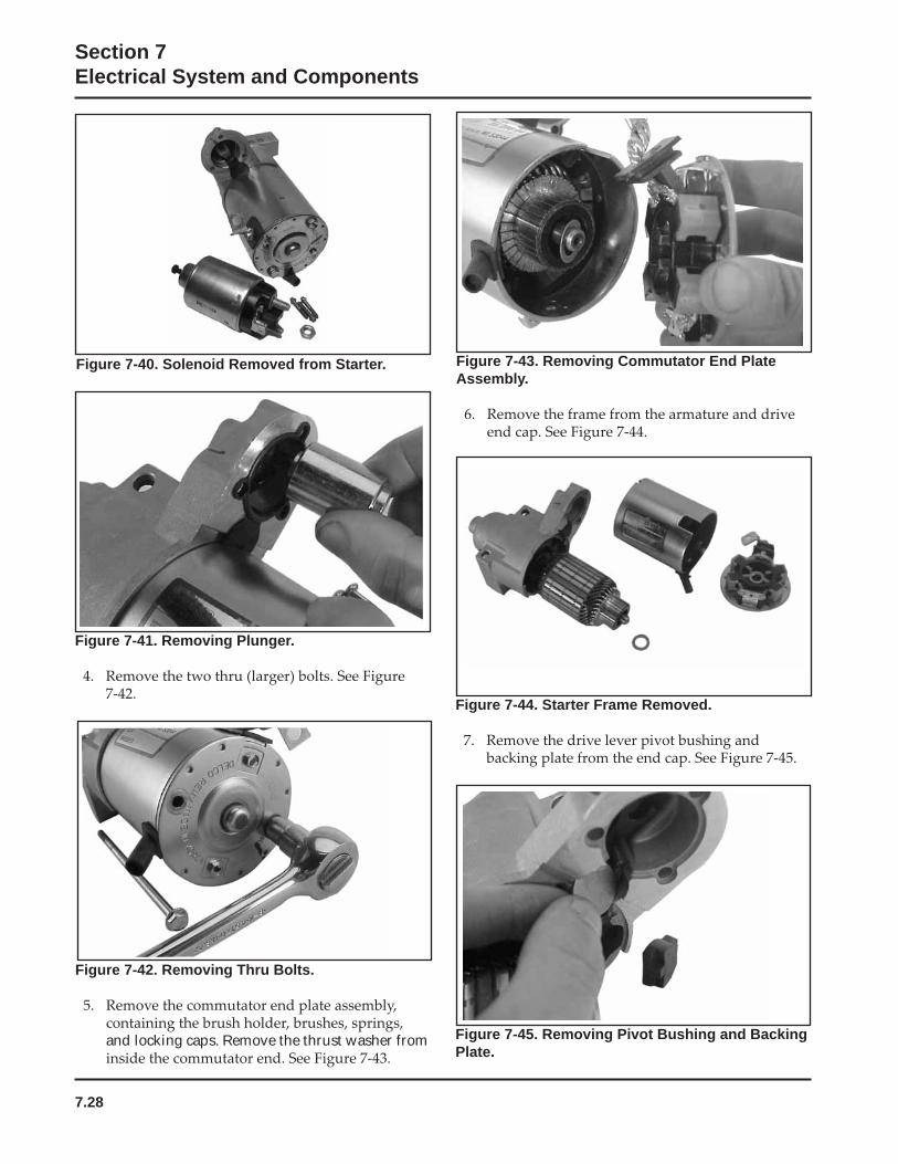
7.28
Section 7Electrical System and Components
Figure 7-42. Removing Thru Bolts.
and locking caps. Remove the thrust washer from
Figure 7-43. Removing Commutator End Plate Assembly.
Figure 7-44. Starter Frame Removed.
Figure 7-45. Removing Pivot Bushing and Backing Plate.
Figure 7-41. Removing Plunger.
Figure 7-40. Solenoid Removed from Starter.
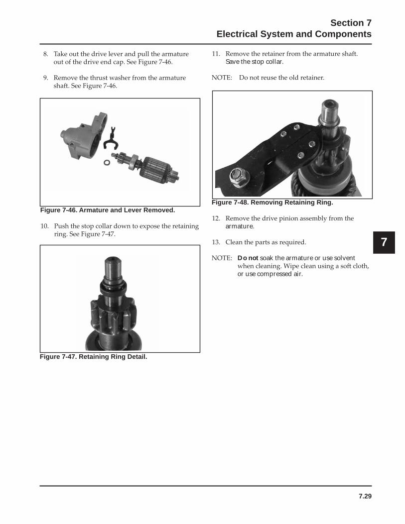
7.29
Section 7Electrical System and Components
7
Figure 7-46. Armature and Lever Removed.
Save the stop collar.
Figure 7-47. Retaining Ring Detail.
Figure 7-48. Removing Retaining Ring.
armature.
Do not soak the armature or use solvent
or use compressed air.
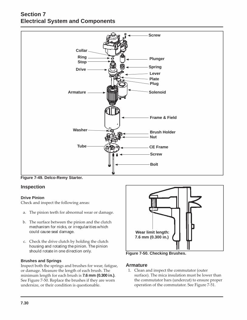
7.30
Section 7Electrical System and Components
Wear limit length:7.6 mm (0.300 in.)
Inspection
Drive Pinion
mechanism for nicks, or irregularities which could cause seal damage.
housing and rotating the pinion. The pinion should rotate in one direction only.
Brushes and Springs
7.6 mm (0.300 in.).
Figure 7-50. Checking Brushes.
Armature
Lever
Solenoid
CE Frame
Bolt
RingStop
Drive
Armature
Washer
Screw
Plunger
Spring
Plate
Collar
Tube
Screw
Plug
Frame & Field
Brush HolderNut
Figure 7-49. Delco-Remy Starter.
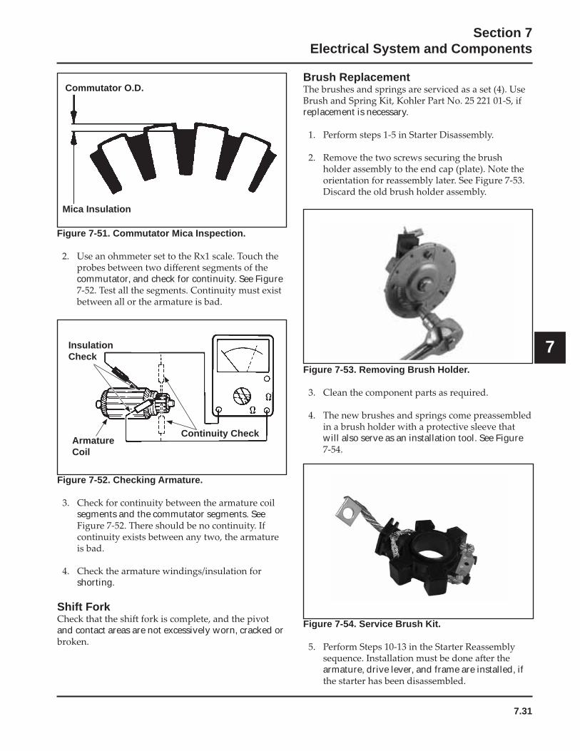
7.31
Section 7Electrical System and Components
7
Commutator O.D.
Mica Insulation
Continuity CheckArmatureCoil
InsulationCheck
Figure 7-51. Commutator Mica Inspection.
commutator, and check for continuity. See Figure
Figure 7-52. Checking Armature.
segments and the commutator segments. See
shorting.
Shift Fork
and contact areas are not excessively worn, cracked or
Brush Replacement
replacement is necessary.
Figure 7-53. Removing Brush Holder.
will also serve as an installation tool. See Figure
Figure 7-54. Service Brush Kit.
armature, drive lever, and frame are installed, if
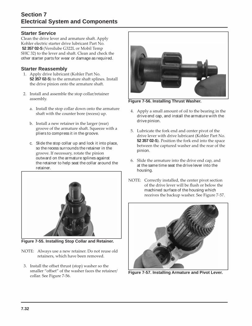
7.32
Section 7Electrical System and Components
Starter Service
52 357 02-S
other starter parts for wear or damage as required.
Starter Reassembly
52 357 02-S
pliers to compress it in the groove.
c. Slide the stop collar up and lock it into place, so the recess surrounds the retainer in the
outward on the armature splines against the retainer to help seat the collar around the retainer.
Figure 7-55. Installing Stop Collar and Retainer.
Figure 7-56. Installing Thrust Washer.
drive end cap, and install the armature with the drive pinion.
52 357 02-S
pinion.
at the same time seat the drive lever into the housing.
machined surface of the housing which
Figure 7-57. Installing Armature and Pivot Lever.
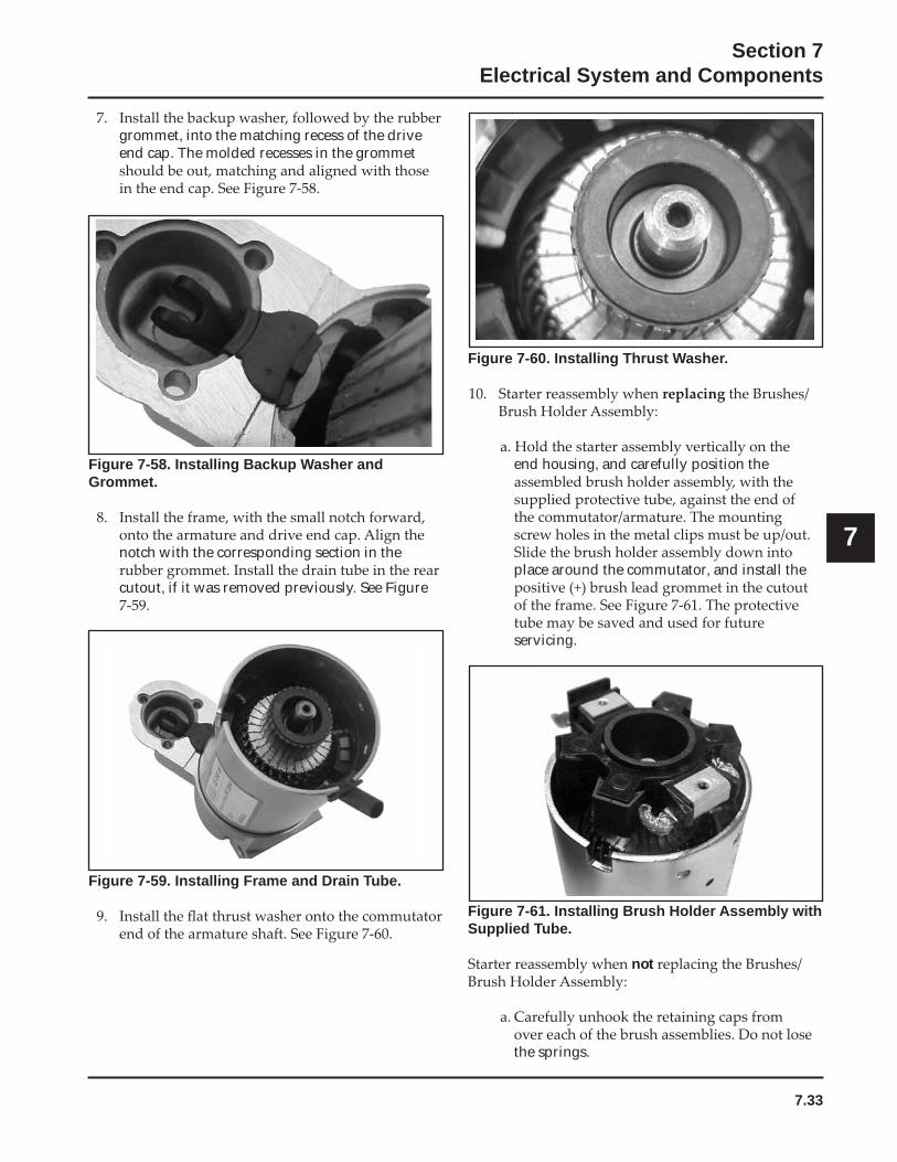
7.33
Section 7Electrical System and Components
7
grommet, into the matching recess of the drive end cap. The molded recesses in the grommet
Figure 7-58. Installing Backup Washer and Grommet.
notch with the corresponding section in the
cutout, if it was removed previously. See Figure
Figure 7-59. Installing Frame and Drain Tube.
Figure 7-60. Installing Thrust Washer.
end housing, and carefully position the
place around the commutator, and install the
servicing.
Figure 7-61. Installing Brush Holder Assembly with Supplied Tube.
not
the springs.
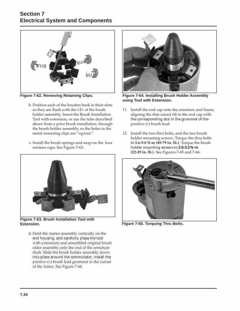
7.34
Section 7Electrical System and Components
Figure 7-62. Removing Retaining Clips.
Figure 7-63. Brush Installation Tool with Extension.
end housing, and carefully place the tool
into place around the commutator, install the
Figure 7-64. Installing Brush Holder Assembly using Tool with Extension.
the corresponding slot in the grommet of the
toholder mounting screws to 2.5-3.3 N·m
Figure 7-65. Torquing Thru Bolts.
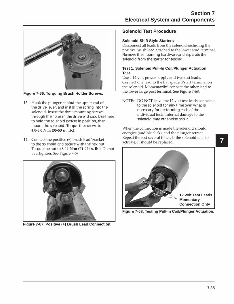
7.35
Section 7Electrical System and Components
7
Figure 7-66. Torquing Brush Holder Screws.
the drive lever, and install the spring into the
through the holes in the drive end cap. Use these to hold the solenoid gasket in position, then mount the solenoid. Torque the screws to
.
to the solenoid and secure with the hex nut. Torque the nut to
Figure 7-67. Positive (+) Brush Lead Connection.
Solenoid Test Procedure
Solenoid Shift Style Starters
Remove the mounting hardware and separate the solenoid from the starter for testing.
Test 1. Solenoid Pull-In Coil/Plunger Actuation Test.
to the solenoid for any time over what isnecessary for performing each of the
solenoid may otherwise occur.
Figure 7-68. Testing Pull-In Coil/Plunger Actuation.
12 volt Test LeadsMomentaryConnection Only
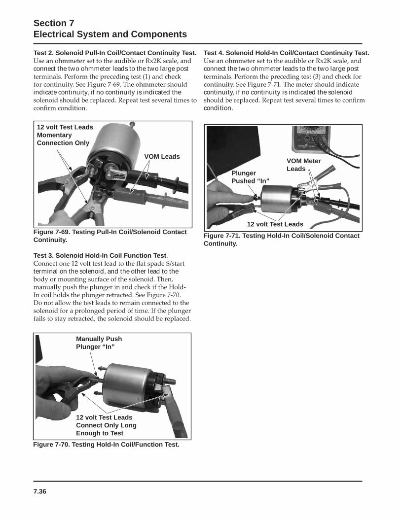
7.36
Section 7Electrical System and Components
Figure 7-69. Testing Pull-In Coil/Solenoid Contact Continuity.
Test 3. Solenoid Hold-In Coil Function Test.
terminal on the solenoid, and the other lead to the
12 volt Test LeadsMomentaryConnection Only
VOM Leads
Figure 7-70. Testing Hold-In Coil/Function Test.
Figure 7-71. Testing Hold-In Coil/Solenoid Contact Continuity.
Manually Push Plunger “In”
12 volt Test LeadsConnect Only Long Enough to Test
PlungerPushed “In”
VOM Meter Leads
12 volt Test Leads
Test 4. Solenoid Hold-In Coil/Contact Continuity Test.
connect the two ohmmeter leads to the two large post
continuity, if no continuity is indicated the solenoid
condition.
Test 2. Solenoid Pull-In Coil/Contact Continuity Test.
connect the two ohmmeter leads to the two large post
indicate continuity, if no continuity is indicated the
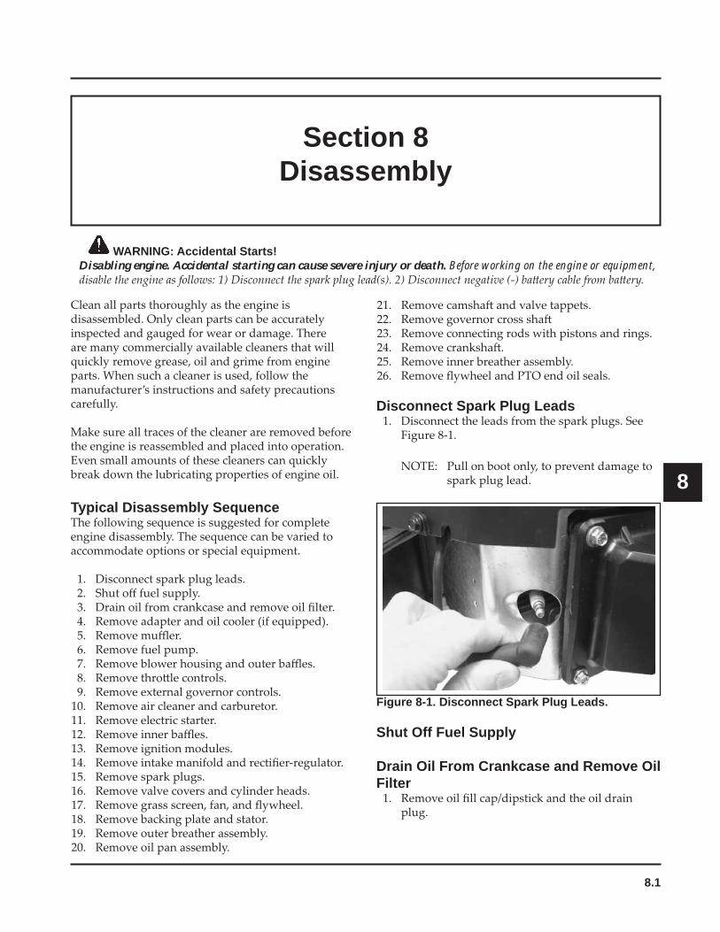
8.1
Section 8Disassembly
8
Section 8Disassembly
WARNING: Accidental Starts!Disabling engine. Accidental starting can cause severe injury or death. Before working on the engine or equipment,
Disconnect Spark Plug Leads
Typical Disassembly Sequence
Figure 8-1. Disconnect Spark Plug Leads.
Shut Off Fuel Supply
Drain Oil From Crankcase and Remove Oil Filter
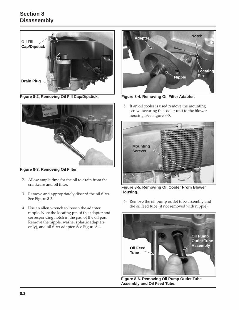
8.2
Section 8Disassembly
Figure 8-3. Removing Oil Filter.
Figure 8-5. Removing Oil Cooler From Blower Housing.
Figure 8-2. Removing Oil Fill Cap/Dipstick.
Oil FillCap/Dipstick
Drain Plug
Figure 8-4. Removing Oil Filter Adapter.
Figure 8-6. Removing Oil Pump Outlet Tube Assembly and Oil Feed Tube.
Oil Feed Tube
Oil Pump Outlet Tube Assembly
MountingScrews
Adapter
NippleLocatingPin
Notch
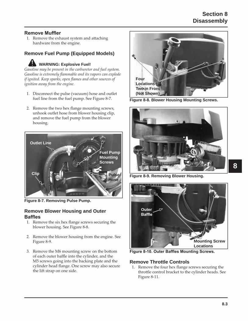
8.3
Section 8Disassembly
8
Figure 8-7. Removing Pulse Pump.
Remove Blower Housing and Outer
Remove Throttle Controls
Remove Fuel Pump (Equipped Models)
WARNING: Explosive Fuel!
Outlet Line
Fuel Pump MountingScrews
PulseHose
Figure 8-8. Blower Housing Mounting Screws.
Figure 8-9. Removing Blower Housing.
FourLocationsTwo in Front (Not Shown)
Outer
Mounting Screw Locations
Clip
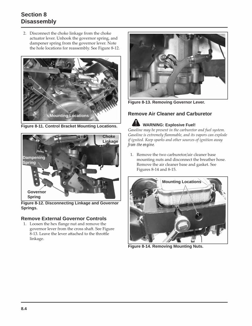
8.4
Section 8Disassembly
Figure 8-12. Disconnecting Linkage and Governor Springs.
Remove External Governor Controls
Figure 8-13. Removing Governor Lever.
Remove Air Cleaner and Carburetor
WARNING: Explosive Fuel!
from the engine.
Figure 8-11. Control Bracket Mounting Locations.
Mounting Locations
ChokeLinkage
DampeningSpring
GovernorSpring
Figure 8-14. Removing Mounting Nuts.
Mounting Locations
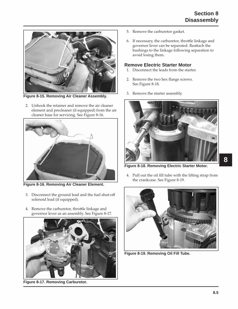
8.5
Section 8Disassembly
8
Figure 8-16. Removing Air Cleaner Element.
Figure 8-18. Removing Electric Starter Motor.
Figure 8-15. Removing Air Cleaner Assembly.
Figure 8-17. Removing Carburetor.
Remove Electric Starter Motor
Figure 8-19. Removing Oil Fill Tube.
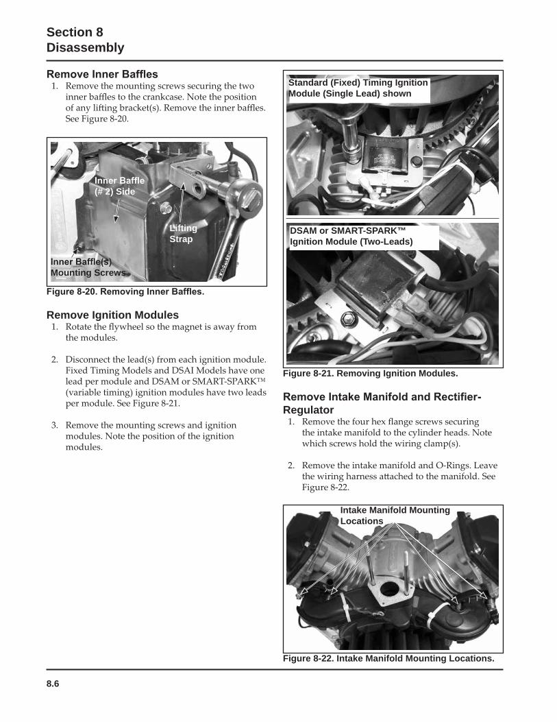
8.6
Section 8Disassembly
Remove Ignition Modules
Figure 8-21. Removing Ignition Modules.
Regulator
Mounting Screws
(# 2) Side
LiftingStrap
Standard (Fixed) Timing Ignition Module (Single Lead) shown
DSAM or SMART-SPARK™ Ignition Module (Two-Leads)
Figure 8-22. Intake Manifold Mounting Locations.
Intake Manifold Mounting Locations
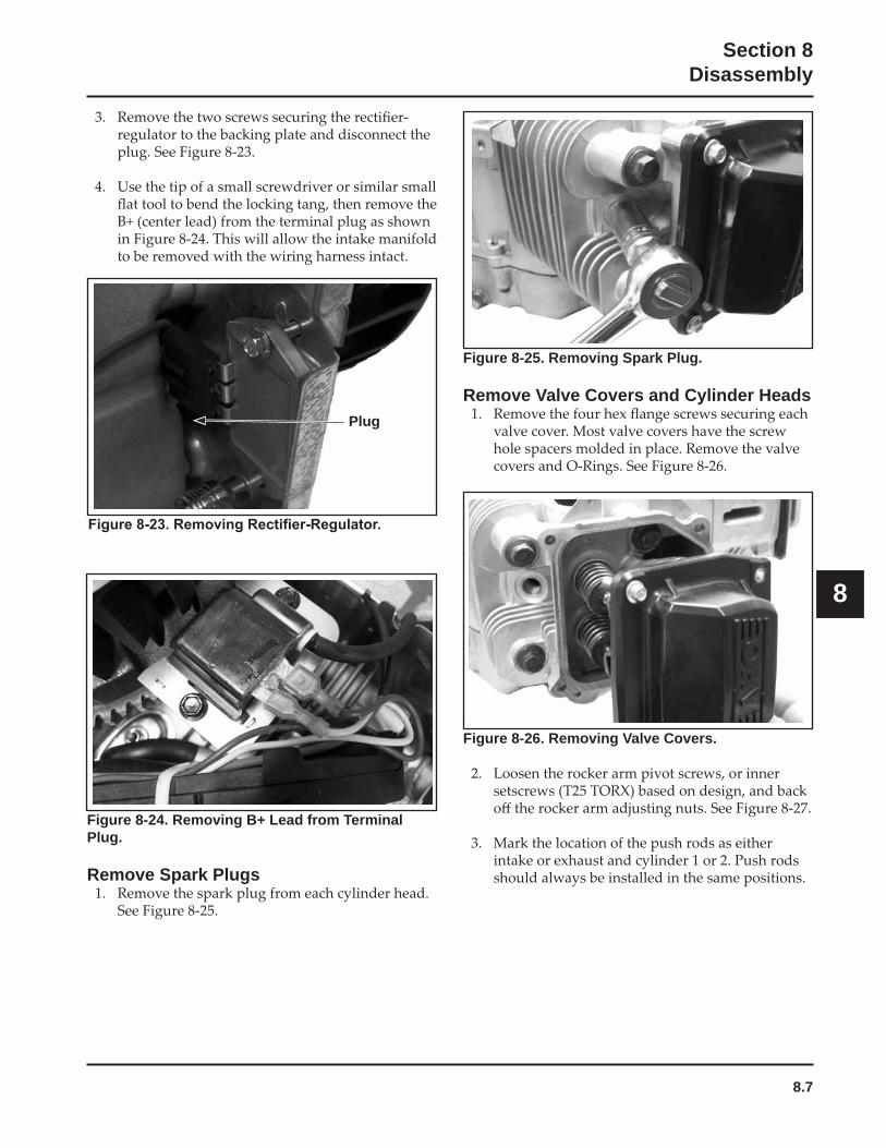
8.7
Section 8Disassembly
8
Figure 8-25. Removing Spark Plug.
Remove Valve Covers and Cylinder HeadsPlug
Figure 8-24. Removing B+ Lead from Terminal Plug.
Remove Spark Plugs
Figure 8-26. Removing Valve Covers.
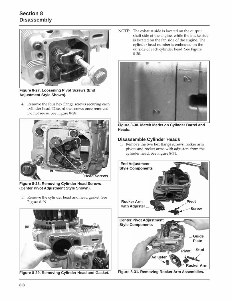
8.8
Section 8Disassembly
Figure 8-29. Removing Cylinder Head and Gasket. Figure 8-31. Removing Rocker Arm Assemblies.
Figure 8-27. Loosening Pivot Screws (End Adjustment Style Shown).
Figure 8-28. Removing Cylinder Head Screws (Center Pivot Adjustment Style Shown).
Figure 8-30. Match Marks on Cylinder Barrel and Heads.
Disassemble Cylinder Heads
Rocker Arm with Adjuster
Pivot
Screw
End Adjustment Style Components
Pivot Stud
GuidePlate
Adjuster
Rocker Arm
Center Pivot Adjustment Style Components
Head Screws
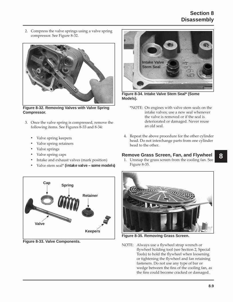
8.9
Section 8Disassembly
8
Figure 8-34. Intake Valve Stem Seal* (Some Models).
Remove Grass Screen, Fan, and Flywheel
Figure 8-33. Valve Components.Figure 8-35. Removing Grass Screen.
Intake Valve Stem Seal
Figure 8-32. Removing Valves with Valve Spring Compressor.
• • • • • • (intake valve – some models)
Cap Spring
Retainer
Valve
Keepers
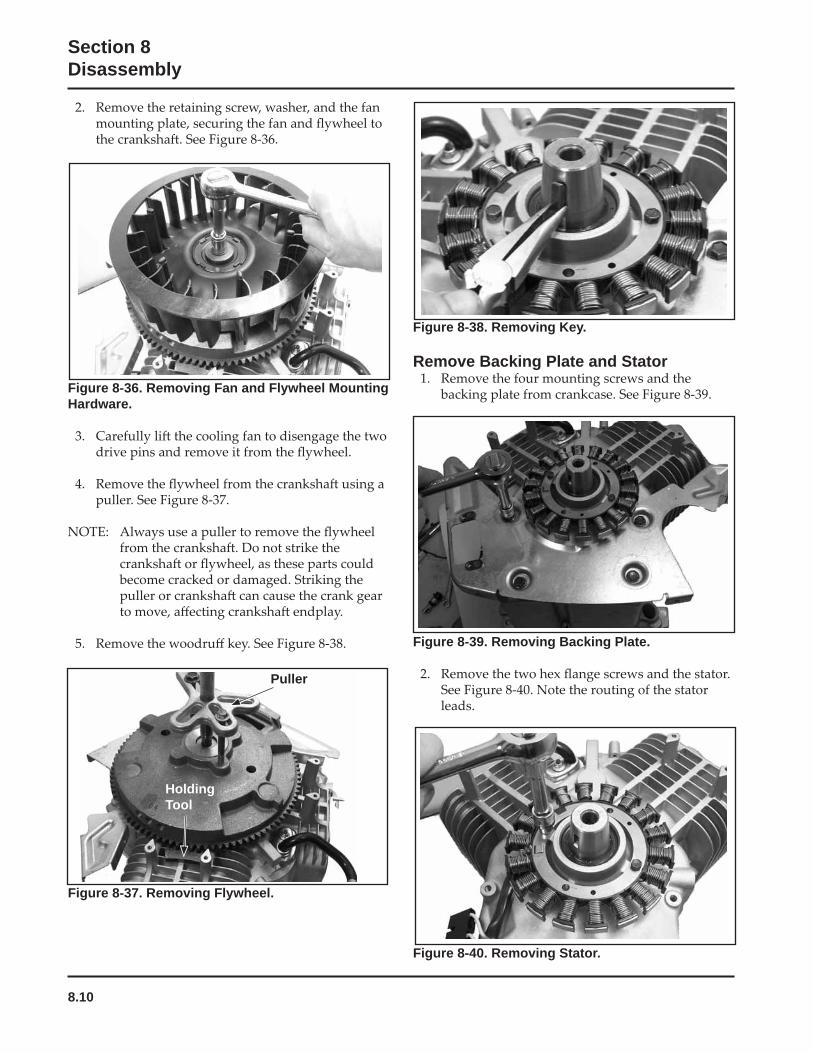
8.10
Section 8Disassembly
Figure 8-36. Removing Fan and Flywheel Mounting Hardware.
Figure 8-40. Removing Stator.
Figure 8-37. Removing Flywheel.
Puller
HoldingTool
Figure 8-38. Removing Key.
Remove Backing Plate and Stator
Figure 8-39. Removing Backing Plate.
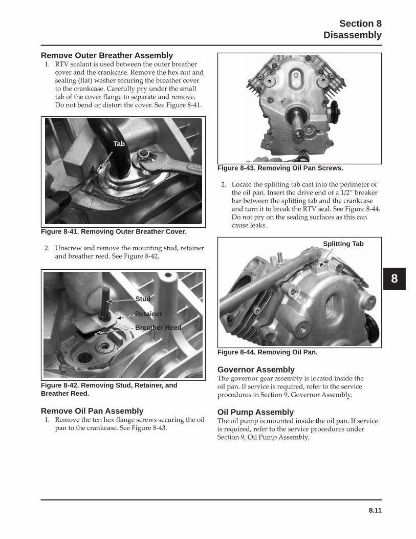
8.11
Section 8Disassembly
8
Figure 8-44. Removing Oil Pan.
Governor Assembly
Oil Pump Assembly
Remove Outer Breather Assembly
Figure 8-41. Removing Outer Breather Cover.
Tab
Figure 8-42. Removing Stud, Retainer, and Breather Reed.
Remove Oil Pan Assembly
Figure 8-43. Removing Oil Pan Screws.
Stud
Retainer
Breather Reed
Splitting Tab
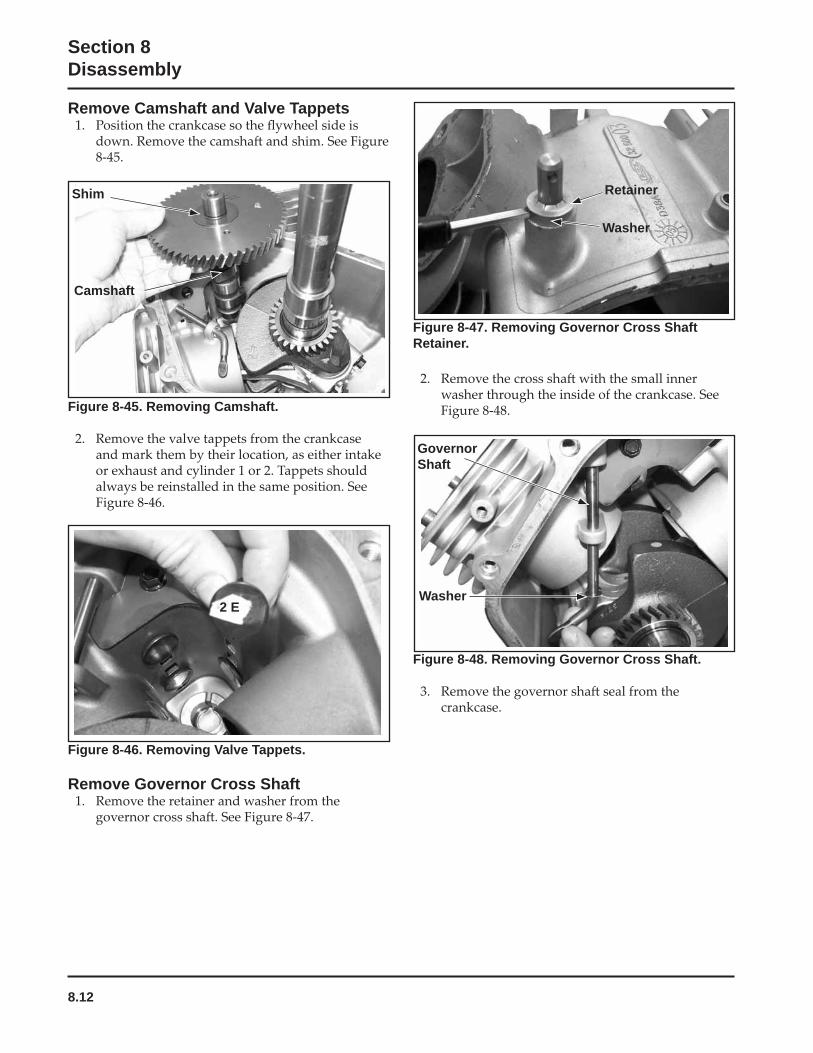
8.12
Section 8Disassembly
Figure 8-46. Removing Valve Tappets.
Remove Governor Cross Shaft
Figure 8-48. Removing Governor Cross Shaft.
Figure 8-45. Removing Camshaft.
Figure 8-47. Removing Governor Cross Shaft Retainer.
Retainer
Washer
GovernorShaft
Washer
Shim
Camshaft
Remove Camshaft and Valve Tappets
2 E
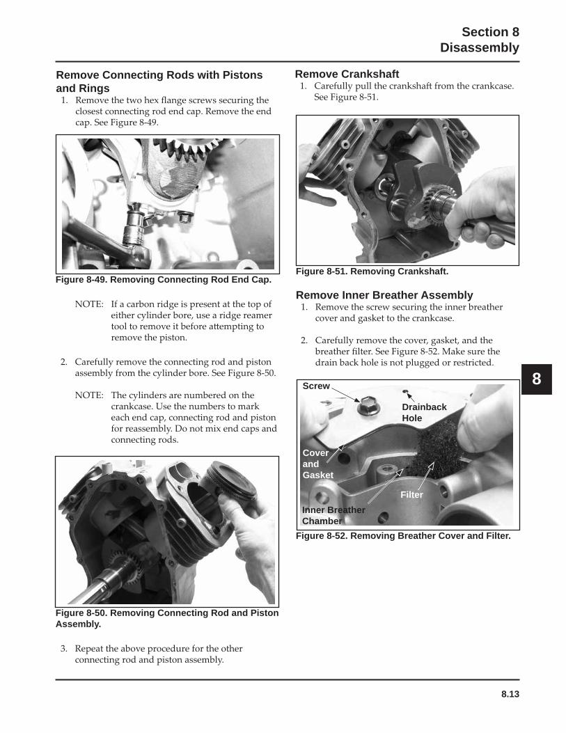
8.13
Section 8Disassembly
8
Figure 8-49. Removing Connecting Rod End Cap.
Figure 8-50. Removing Connecting Rod and Piston Assembly.
Figure 8-51. Removing Crankshaft.
Remove Inner Breather Assembly
Figure 8-52. Removing Breather Cover and Filter.
Screw
CoverandGasket
Inner Breather Chamber
DrainbackHole
Filter
Remove CrankshaftRemove Connecting Rods with Pistons and Rings
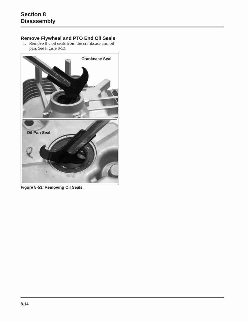
8.14
Section 8Disassembly
Remove Flywheel and PTO End Oil Seals
Figure 8-53. Removing Oil Seals.
Oil Pan Seal
Crankcase Seal
9.1
Section 9Inspection and Reconditioning
9
Section 9Inspection and Reconditioning
This section covers the operation, inspection, and repair/reconditioning of major internal engine components. The following components are not covered in this section. They are covered in sections of their own:
Section 4: Air Cleaner and Intake System Section 5: Carburetor & External Governor Section 7: Ignition, Charging & Electric Starter
Clean all parts thoroughly. Only clean parts can be accurately inspected and gauged for wear or damage. There are many commercially available cleaners that will quickly remove grease, oil, and grime from engine parts. When such a cleaner is used, follow the manufacturer’s instructions and safety precautions carefully. Make sure all traces of the cleaner are removed before the engine is reassembled and placed into operation. Even small amounts of these cleaners can quickly break down the lubricating properties of engine oil.
Use an aerosol gasket remover, paint stripper, or lacquer thinner to remove any old sealant. Apply the solvent, allow time for it to work, and then brush the
is removed, clean the surface with isopropyl alcohol, lacquer thinner, or aerosol electrical contact cleaner. Do not scrape the surfaces, as any scratches, nicks, or burrs can result in leaks.
Refer to A Guide to Engine Rebuilding (TP-2150-A) for additional information. Measurement Guide (TP-2159-B) and Engine Inspection Data Record (TP-2435) are also available; use these to record inspection results.
Automatic Compression Release (ACR)Some engines may be equipped with the optional Automatic Compression Release (ACR) mechanism. The ACR lowers compression at cranking speeds to make starting easier.
Camshaft
Inspection and Service
badly worn, chipped or missing teeth. Replacement
conditions exist.
Crankshaft
Inspection and Service
are badly worn, chipped, or some are missing,
grooving, etc. Measure the running clearance between
bores. Use an inside micrometer or telescoping gauge to measure the inside diameter of both bearing bores in the vertical and horizontal planes. Use an outside micrometer to measure the outside diameter of the
diameters from their respective bore diameters to get the running clearances. Check the results against the
and there is no evidence of scoring, grooving, etc., no further reconditioning is necessary. If the bearing surfaces are worn or damaged, the crankcase and/or oil pan will need to be replaced.
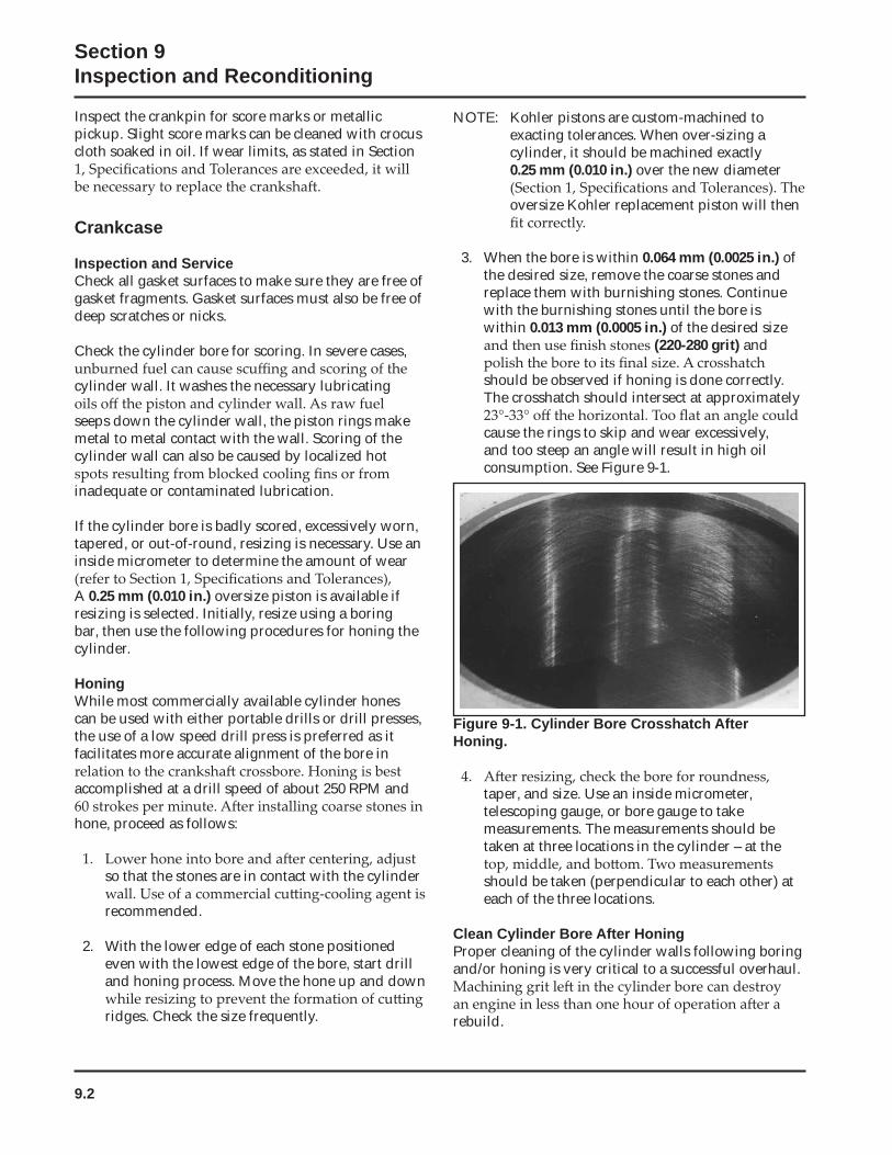
9.2
Section 9Inspection and Reconditioning
Inspect the crankpin for score marks or metallic pickup. Slight score marks can be cleaned with crocus cloth soaked in oil. If wear limits, as stated in Section
Crankcase
Inspection and ServiceCheck all gasket surfaces to make sure they are free of gasket fragments. Gasket surfaces must also be free of deep scratches or nicks.
Check the cylinder bore for scoring. In severe cases,
cylinder wall. It washes the necessary lubricating
seeps down the cylinder wall, the piston rings make metal to metal contact with the wall. Scoring of the cylinder wall can also be caused by localized hot
inadequate or contaminated lubrication.
If the cylinder bore is badly scored, excessively worn, tapered, or out-of-round, resizing is necessary. Use an inside micrometer to determine the amount of wear
A 0.25 mm (0.010 in.) oversize piston is available if resizing is selected. Initially, resize using a boring bar, then use the following procedures for honing the cylinder.
HoningWhile most commercially available cylinder hones can be used with either portable drills or drill presses, the use of a low speed drill press is preferred as it facilitates more accurate alignment of the bore in
accomplished at a drill speed of about 250 RPM and
hone, proceed as follows:
so that the stones are in contact with the cylinder
recommended.
2. With the lower edge of each stone positioned even with the lowest edge of the bore, start drill and honing process. Move the hone up and down
ridges. Check the size frequently.
NOTE: Kohler pistons are custom-machined to exacting tolerances. When over-sizing a cylinder, it should be machined exactly0.25 mm (0.010 in.) over the new diameter
oversize Kohler replacement piston will then
3. When the bore is within 0.064 mm (0.0025 in.) of the desired size, remove the coarse stones and replace them with burnishing stones. Continue with the burnishing stones until the bore is within 0.013 mm (0.0005 in.) of the desired size
(220-280 grit) and
should be observed if honing is done correctly. The crosshatch should intersect at approximately
cause the rings to skip and wear excessively, and too steep an angle will result in high oil consumption. See Figure 9-1.
Figure 9-1. Cylinder Bore Crosshatch After Honing.
taper, and size. Use an inside micrometer, telescoping gauge, or bore gauge to take measurements. The measurements should be taken at three locations in the cylinder – at the
should be taken (perpendicular to each other) at each of the three locations.
Clean Cylinder Bore After HoningProper cleaning of the cylinder walls following boring and/or honing is very critical to a successful overhaul.
rebuild.
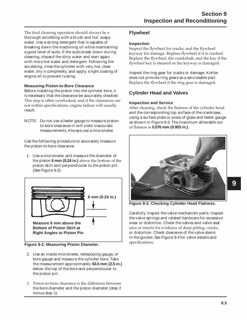
9.3
Section 9Inspection and Reconditioning
9
thorough scrubbing with a brush and hot, soapy water. Use a strong detergent that is capable of breaking down the machining oil while maintaining a good level of suds. If the suds break down during cleaning, discard the dirty water and start again with more hot water and detergent. Following the scrubbing, rinse the cylinder with very hot, clear water, dry it completely, and apply a light coating of engine oil to prevent rusting.
Measuring Piston-to-Bore ClearanceBefore installing the piston into the cylinder bore, it is necessary that the clearance be accurately checked.
result.
NOTE: Do not use a feeler gauge to measure piston-to-bore clearance–it will yield inaccurate measurements. Always use a micrometer.
Use the following procedure to accurately measure the piston-to-bore clearance:
1. Use a micrometer and measure the diameter of the piston 6 mm (0.24 in.)piston skirt and perpendicular to the piston pin (See Figure 9-2).
Figure 9-3. Checking Cylinder Head Flatness.
Carefully inspect the valve mechanism parts. Inspect the valve springs and related hardware for excessive wear or distortion. Check the valves and valve seat
or distortion. Check clearance of the valve stems in the guides. See Figure 9-4 for valve details and
Figure 9-2. Measuring Piston Diameter.
2. Use an inside micrometer, telescoping gauge, or bore gauge and measure the cylinder bore. Take the measurement approximately 63.5 mm (2.5 in.)below the top of the bore and perpendicular to the piston pin.
the bore diameter and the piston diameter (step 2 minus step 1).
Flywheel
Inspection
Inspect the ring gear for cracks or damage. Kohler does not provide ring gears as a serviceable part.
Cylinder Head and Valves
Inspection and Service
and the corresponding top surface of the crankcase, using a surface plate or piece of glass and feeler gauge as shown in Figure 9-3. The maximum allowable out
0.076 mm (0.003 in.).
6 mm (0.24 in.)
Measure 6 mm above the Bottom of Piston Skirt at Right Angles to Piston Pin
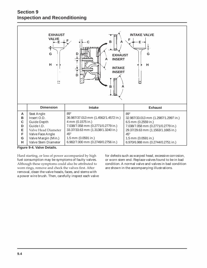
9.4
Section 9Inspection and Reconditioning
EXHAUSTVALVE
E
G
F
H
D
D
C
A
B A
B A FE
G
H
INTAKE VALVE
EXHAUST INSERT
INTAKE INSERT
ABCDEFGH
Seat AngleInsert O.D.Guide DepthGuide I.D.
Valve Face AngleValve Margin (Min.)Valve Stem Diameter
Dimension
89°36.987/37.013 mm (1.4562/1.4572 in.)4 mm (0.1575 in.)7.038/7.058 mm (0.2771/0.2779 in.)33.37/33.63 mm (1.3138/1.3240 in.)45°1.5 mm (0.0591 in.)6.982/7.000 mm (0.2749/0.2756 in.)
Intake Exhaust
89°32.987/33.013 mm (1.2987/1.2997 in.)6.5 mm (0.2559 in.)7.038/7.058 mm (0.2771/0.2779 in.)29.37/29.63 mm (1.1563/1.1665 in.)45°1.5 mm (0.0591 in.)6.970/6.988 mm (0.2744/0.2751 in.)
Figure 9-4. Valve Details.
fuel consumption may be symptoms of faulty valves.
removal, clean the valve heads, faces, and stems with a power wire brush. Then, carefully inspect each valve
for defects such as warped head, excessive corrosion, or worn stem end. Replace valves found to be in bad condition. A normal valve and valves in bad condition are shown in the accompanying illustrations.
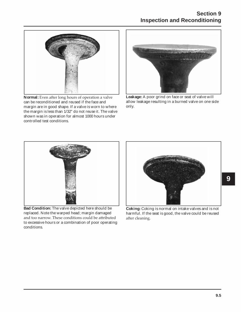
9.5
Section 9Inspection and Reconditioning
9
Normal:can be reconditioned and reused if the face and margin are in good shape. If a valve is worn to where the margin is less than 1/32" do not reuse it. The valve shown was in operation for almost 1000 hours under controlled test conditions.
Bad Condition: The valve depicted here should be replaced. Note the warped head; margin damaged
to excessive hours or a combination of poor operating conditions.
Leakage: A poor grind on face or seat of valve will allow leakage resulting in a burned valve on one side only.
Coking: Coking is normal on intake valves and is not harmful. If the seat is good, the valve could be reused
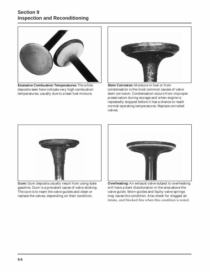
9.6
Section 9Inspection and Reconditioning
Excessive Combustion Temperatures: The white deposits seen here indicate very high combustion temperatures, usually due to a lean fuel mixture.
Gum: Gum deposits usually result from using stale gasoline. Gum is a prevalent cause of valve sticking. The cure is to ream the valve guides and clean or replace the valves, depending on their condition.
Stem Corrosion: Moisture in fuel or from condensation is the most common causes of valve stem corrosion. Condensation occurs from improper preservation during storage and when engine is repeatedly stopped before it has a chance to reach normal operating temperatures. Replace corroded valves.
Overheating: An exhaust valve subject to overheating will have a dark discoloration in the area above the valve guide. Worn guides and faulty valve springs may cause this condition. Also check for clogged air
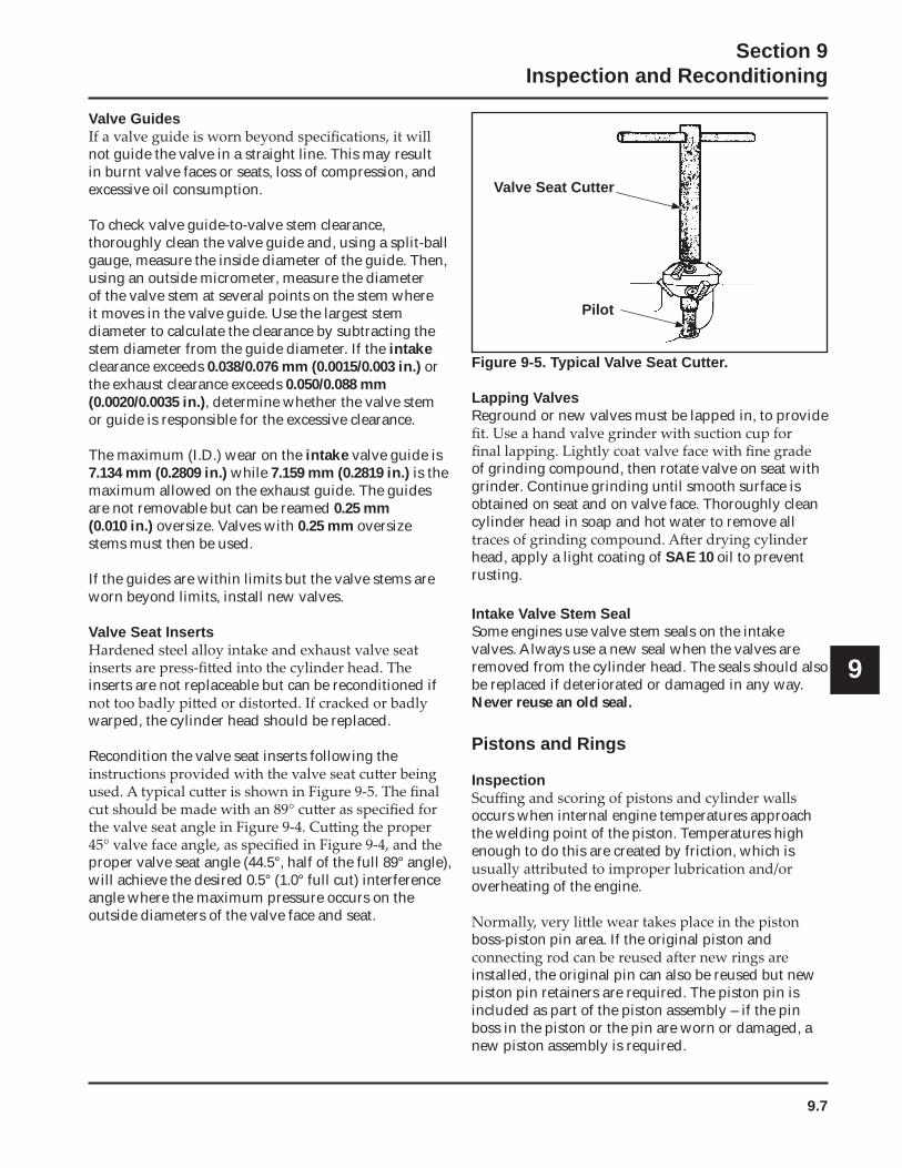
9.7
Section 9Inspection and Reconditioning
9
Valve Guides
not guide the valve in a straight line. This may result in burnt valve faces or seats, loss of compression, and excessive oil consumption.
To check valve guide-to-valve stem clearance, thoroughly clean the valve guide and, using a split-ball gauge, measure the inside diameter of the guide. Then, using an outside micrometer, measure the diameter of the valve stem at several points on the stem where it moves in the valve guide. Use the largest stem diameter to calculate the clearance by subtracting the stem diameter from the guide diameter. If the intakeclearance exceeds 0.038/0.076 mm (0.0015/0.003 in.) or the exhaust clearance exceeds 0.050/0.088 mm (0.0020/0.0035 in.), determine whether the valve stem or guide is responsible for the excessive clearance.
The maximum (I.D.) wear on the intake valve guide is 7.134 mm (0.2809 in.) while 7.159 mm (0.2819 in.) is the maximum allowed on the exhaust guide. The guides are not removable but can be reamed 0.25 mm (0.010 in.) oversize. Valves with 0.25 mm oversize stems must then be used.
If the guides are within limits but the valve stems are worn beyond limits, install new valves.
Valve Seat Inserts
inserts are not replaceable but can be reconditioned if
warped, the cylinder head should be replaced.
Recondition the valve seat inserts following the
proper valve seat angle (44.5°, half of the full 89° angle), will achieve the desired 0.5° (1.0° full cut) interference angle where the maximum pressure occurs on the outside diameters of the valve face and seat.
Figure 9-5. Typical Valve Seat Cutter.
Lapping ValvesReground or new valves must be lapped in, to provide
of grinding compound, then rotate valve on seat with grinder. Continue grinding until smooth surface is obtained on seat and on valve face. Thoroughly clean cylinder head in soap and hot water to remove all
head, apply a light coating of SAE 10 oil to prevent rusting.
Intake Valve Stem SealSome engines use valve stem seals on the intake valves. Always use a new seal when the valves are removed from the cylinder head. The seals should also be replaced if deteriorated or damaged in any way. Never reuse an old seal.
Pistons and Rings
Inspection
occurs when internal engine temperatures approach the welding point of the piston. Temperatures high enough to do this are created by friction, which is
overheating of the engine.
boss-piston pin area. If the original piston and
installed, the original pin can also be reused but new piston pin retainers are required. The piston pin is included as part of the piston assembly – if the pin boss in the piston or the pin are worn or damaged, a new piston assembly is required.
Valve Seat Cutter
Pilot
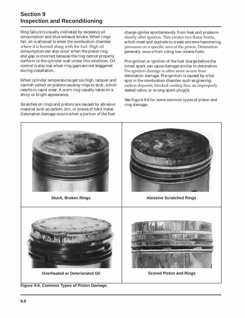
9.8
Section 9Inspection and Reconditioning
Ring failure is usually indicated by excessive oil consumption and blue exhaust smoke. When rings fail, oil is allowed to enter the combustion chamber
consumption can also occur when the piston ring end gap is incorrect because the ring cannot properly conform to the cylinder wall under this condition. Oil control is also lost when ring gaps are not staggered during installation.
When cylinder temperatures get too high, lacquer and varnish collect on pistons causing rings to stick, which results in rapid wear. A worn ring usually takes on a shiny or bright appearance.
Scratches on rings and pistons are caused by abrasive material such as carbon, dirt, or pieces of hard metal.Detonation damage occurs when a portion of the fuel
charge ignites spontaneously from heat and pressure
which meet and explode to create extreme hammering
generally occurs from using low octane fuels.
Pre-ignition or ignition of the fuel charge before the timed spark can cause damage similar to detonation.
detonation damage. Pre-ignition is caused by a hot spot in the combustion chamber such as glowing
seated valve, or wrong spark plug(s).
See Figure 9-6 for some common types of piston and ring damage.
Overheated or Deteriorated Oil Scored Piston and Rings
Abrasive Scratched RingsStuck, Broken Rings
Figure 9-6. Common Types of Piston Damage.
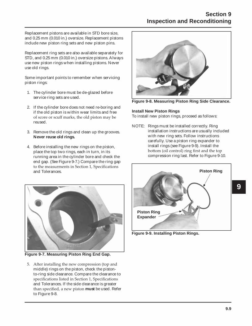
9.9
Section 9Inspection and Reconditioning
9
Piston Ring
Piston RingExpander
Replacement pistons are available in STD bore size, and 0.25 mm (0.010 in.) oversize. Replacement pistons include new piston ring sets and new piston pins.
Replacement ring sets are also available separately for STD, and 0.25 mm (0.010 in.) oversize pistons. Always use new piston rings when installing pistons. Never use old rings.
Some important points to remember when servicing piston rings:
1. The cylinder bore must be de-glazed before service ring sets are used.
2. If the cylinder bore does not need re-boring and if the old piston is within wear limits and free
reused.
3. Remove the old rings and clean up the grooves. Never reuse old rings.
4. Before installing the new rings on the piston, place the top two rings, each in turn, in its running area in the cylinder bore and check the end gap. (See Figure 9-7.) Compare the ring gap
and Tolerances.
Figure 9-7. Measuring Piston Ring End Gap.
middle) rings on the piston, check the piston-to-ring side clearance. Compare the clearance to
and Tolerances. If the side clearance is greater must be used. Refer
to Figure 9-8.
Figure 9-8. Measuring Piston Ring Side Clearance.
Install New Piston RingsTo install new piston rings, proceed as follows:
NOTE: Rings must be installed correctly. Ring installation instructions are usually included with new ring sets. Follow instructions carefully. Use a piston ring expander to install rings (see Figure 9-9). Install the
compression ring last. Refer to Figure 9-10.
Figure 9-9. Installing Piston Rings.
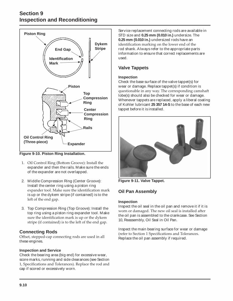
9.10
Section 9Inspection and Reconditioning
Figure 9-10. Piston Ring Installation.
expander and then the rails. Make sure the ends of the expander are not overlapped.
2. Middle Compression Ring (Center Groove): Install the center ring using a piston ring
is up or the dykem stripe (if contained) is to the
3. Top Compression Ring (Top Groove): Install the top ring using a piston ring expander tool. Make
Connecting Rods
these engines.
Inspection and ServiceCheck the bearing area (big end) for excessive wear, score marks, running and side clearances (see Section
cap if scored or excessively worn.
Figure 9-11. Valve Tappet.
Oil Pan Assembly
InspectionInspect the oil seal in the oil pan and remove it if it is
the oil pan is assembled to the crankcase. See Section 10, Reassembly, Oil Seal in Oil Pan.
Inspect the main bearing surface for wear or damage
Replace the oil pan assembly if required.
Piston Ring
End Gap
Mark
DykemStripe
Piston
Top CompressionRing
CenterCompressionRing
Rails
Expander
Oil Control Ring (Three-piece)
Service replacement connecting rods are available in STD size and 0.25 mm (0.010 in.) undersize. The0.25 mm (0.010 in.) undersized rods have an
rod shank. Always refer to the appropriate parts information to ensure that correct replacements are used.
Valve Tappets
InspectionCheck the base surface of the valve tappet(s) for wear or damage. Replace tappet(s) if condition is
lobe(s) should also be checked for wear or damage. Whenever tappets are replaced, apply a liberal coating of Kohler lubricant 25 357 14-S to the base of each new tappet before it is installed.
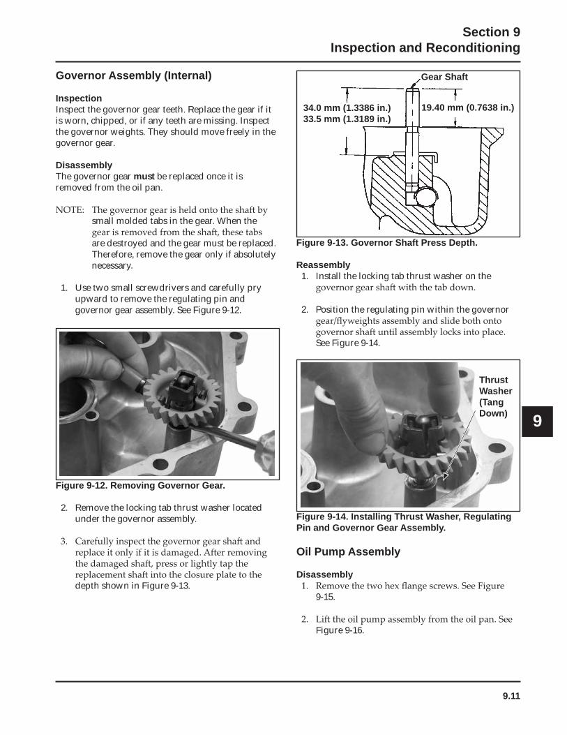
9.11
Section 9Inspection and Reconditioning
9
Figure 9-12. Removing Governor Gear.
2. Remove the locking tab thrust washer located under the governor assembly.
depth shown in Figure 9-13.
Figure 9-13. Governor Shaft Press Depth.
Reassembly1. Install the locking tab thrust washer on the
2. Position the regulating pin within the governor
See Figure 9-14.
Governor Assembly (Internal)
InspectionInspect the governor gear teeth. Replace the gear if it is worn, chipped, or if any teeth are missing. Inspect the governor weights. They should move freely in the governor gear.
DisassemblyThe governor gear must be replaced once it is removed from the oil pan.
small molded tabs in the gear. When the
are destroyed and the gear must be replaced. Therefore, remove the gear only if absolutely necessary.
1. Use two small screwdrivers and carefully pry upward to remove the regulating pin and governor gear assembly. See Figure 9-12.
Figure 9-14. Installing Thrust Washer, Regulating Pin and Governor Gear Assembly.
Oil Pump Assembly
Disassembly
9-15.
Figure 9-16.
ThrustWasher (Tang Down)
Gear Shaft
34.0 mm (1.3386 in.)33.5 mm (1.3189 in.)
19.40 mm (0.7638 in.)
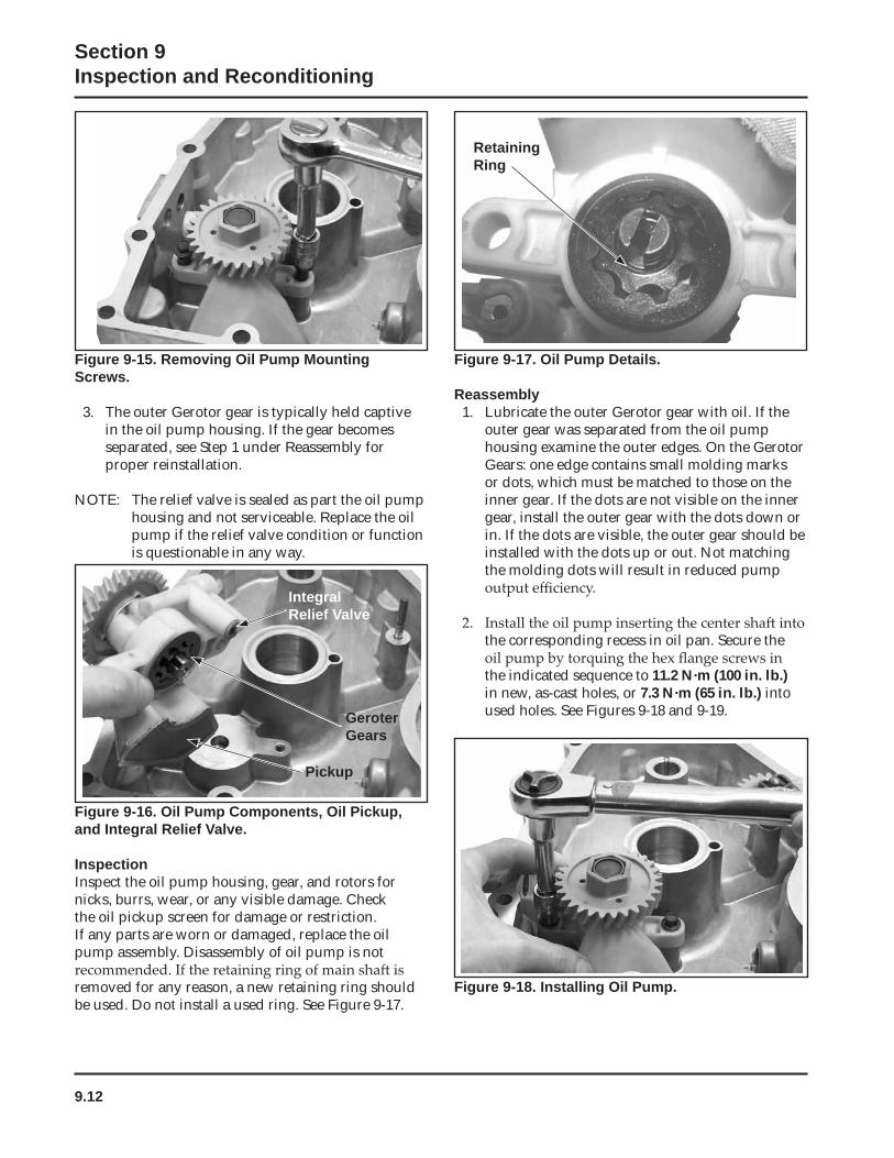
9.12
Section 9Inspection and Reconditioning
Figure 9-17. Oil Pump Details.
Reassembly1. Lubricate the outer Gerotor gear with oil. If the
outer gear was separated from the oil pump housing examine the outer edges. On the Gerotor Gears: one edge contains small molding marks or dots, which must be matched to those on the inner gear. If the dots are not visible on the inner gear, install the outer gear with the dots down or in. If the dots are visible, the outer gear should be installed with the dots up or out. Not matching the molding dots will result in reduced pump
the corresponding recess in oil pan. Secure the
the indicated sequence to 11.2 N·m (100 in. lb.)in new, as-cast holes, or 7.3 N·m (65 in. lb.) into used holes. See Figures 9-18 and 9-19.
Figure 9-15. Removing Oil Pump Mounting Screws.
3. The outer Gerotor gear is typically held captive in the oil pump housing. If the gear becomes separated, see Step 1 under Reassembly for proper reinstallation.
NOTE: The relief valve is sealed as part the oil pump housing and not serviceable. Replace the oil pump if the relief valve condition or function is questionable in any way.
Figure 9-16. Oil Pump Components, Oil Pickup,and Integral Relief Valve.
InspectionInspect the oil pump housing, gear, and rotors for nicks, burrs, wear, or any visible damage. Check the oil pickup screen for damage or restriction. If any parts are worn or damaged, replace the oil pump assembly. Disassembly of oil pump is not
removed for any reason, a new retaining ring should be used. Do not install a used ring. See Figure 9-17.
GeroterGears
IntegralRelief Valve
Pickup
Figure 9-18. Installing Oil Pump.
RetainingRing
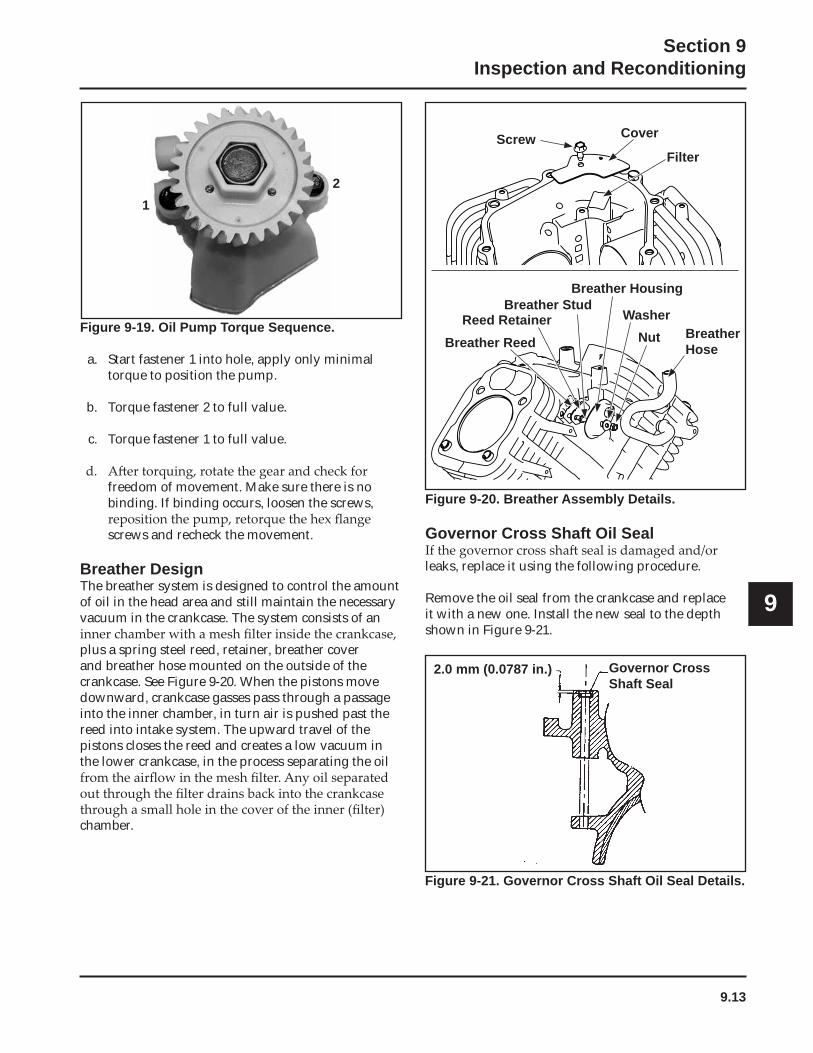
9.13
Section 9Inspection and Reconditioning
9
Figure 9-20. Breather Assembly Details.
Governor Cross Shaft Oil Seal
leaks, replace it using the following procedure.
Remove the oil seal from the crankcase and replace it with a new one. Install the new seal to the depth shown in Figure 9-21.
2.0 mm (0.0787 in.) Governor Cross Shaft Seal
Figure 9-19. Oil Pump Torque Sequence.
a. Start fastener 1 into hole, apply only minimal torque to position the pump.
b. Torque fastener 2 to full value.
c. Torque fastener 1 to full value.
freedom of movement. Make sure there is no binding. If binding occurs, loosen the screws,
screws and recheck the movement.
Breather Design The breather system is designed to control the amount of oil in the head area and still maintain the necessary vacuum in the crankcase. The system consists of an
plus a spring steel reed, retainer, breather cover and breather hose mounted on the outside of the crankcase. See Figure 9-20. When the pistons move downward, crankcase gasses pass through a passage into the inner chamber, in turn air is pushed past the reed into intake system. The upward travel of the pistons closes the reed and creates a low vacuum in the lower crankcase, in the process separating the oil
chamber.
Screw Cover
Filter
Breather Reed
Breather StudReed Retainer Washer
Breather Housing
Nut BreatherHose
Figure 9-21. Governor Cross Shaft Oil Seal Details.
12
9.14
Section 9Inspection and Reconditioning
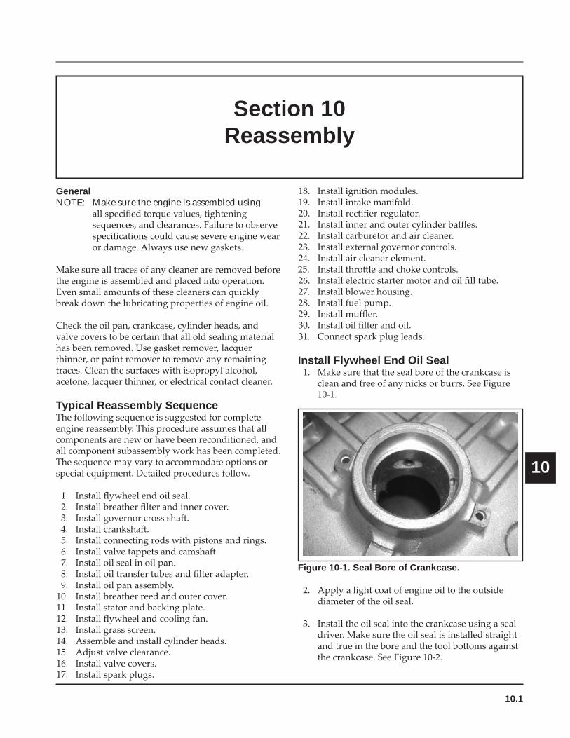
10.1
Section 10Reassembly
10
Section 10Reassembly
GeneralNOTE: Make sure the engine is assembled using
Typical Reassembly Sequence
Install Flywheel End Oil Seal
Figure 10-1. Seal Bore of Crankcase.
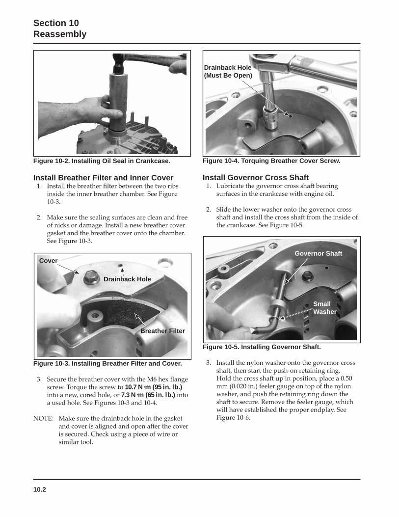
10.2
Section 10Reassembly
Figure 10-2. Installing Oil Seal in Crankcase.
Install Breather Filter and Inner Cover
Figure 10-4. Torquing Breather Cover Screw.
Install Governor Cross Shaft
Figure 10-3. Installing Breather Filter and Cover.
10.7 N·m (95 in. lb.)7.3 N·m (65 in. lb.)
Figure 10-5. Installing Governor Shaft.
Cover
Drainback Hole
Breather Filter
Governor Shaft
SmallWasher
Drainback Hole(Must Be Open)
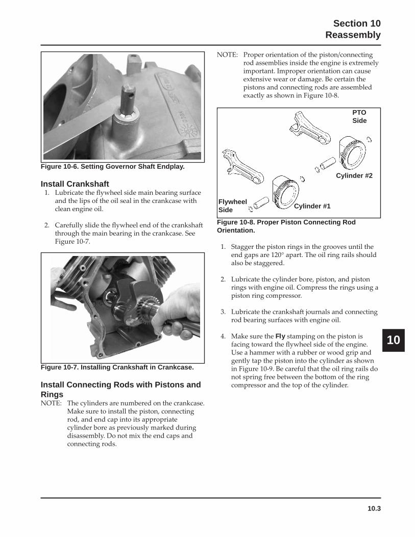
10.3
Section 10Reassembly
10
Figure 10-8. Proper Piston Connecting Rod Orientation.
Fly
Figure 10-6. Setting Governor Shaft Endplay.
Install Crankshaft
Figure 10-7. Installing Crankshaft in Crankcase.
Install Connecting Rods with Pistons and Rings
Cylinder #1
Cylinder #2
FlywheelSide
PTOSide
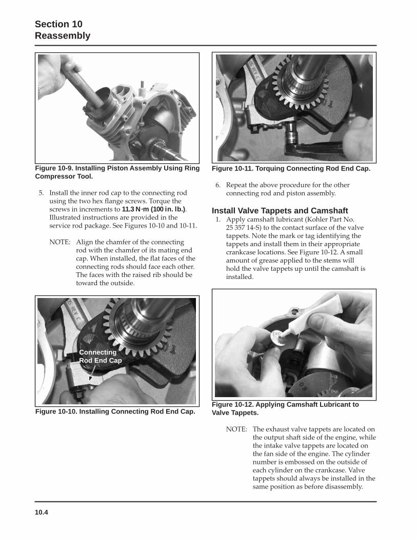
10.4
Section 10Reassembly
Figure 10-9. Installing Piston Assembly Using Ring Compressor Tool.
11.3 N·m (100 in. lb.)
Figure 10-11. Torquing Connecting Rod End Cap.
Install Valve Tappets and Camshaft
Figure 10-12. Applying Camshaft Lubricant to Valve Tappets.Figure 10-10. Installing Connecting Rod End Cap.
ConnectingRod End Cap
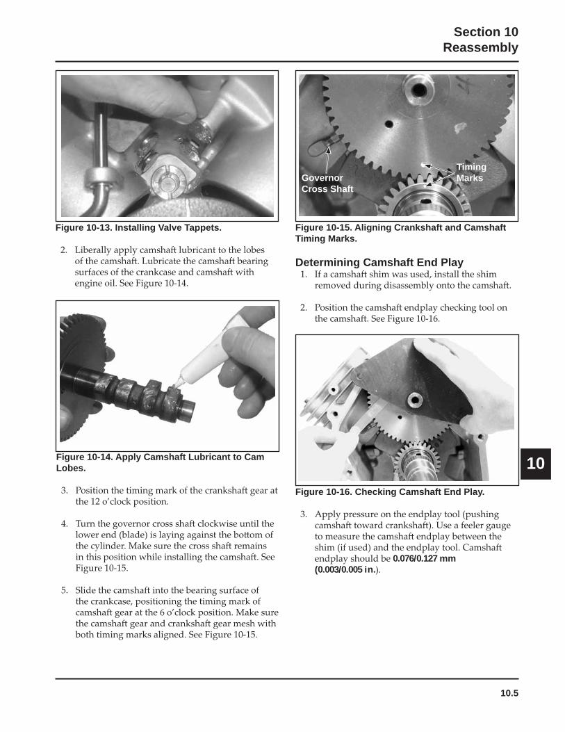
10.5
Section 10Reassembly
10Figure 10-14. Apply Camshaft Lubricant to Cam Lobes.
Figure 10-15. Aligning Crankshaft and Camshaft Timing Marks.
Determining Camshaft End Play
Figure 10-16. Checking Camshaft End Play.
0.076/0.127 mm (0.003/0.005 in.
Figure 10-13. Installing Valve Tappets.
GovernorCross Shaft
Timing Marks
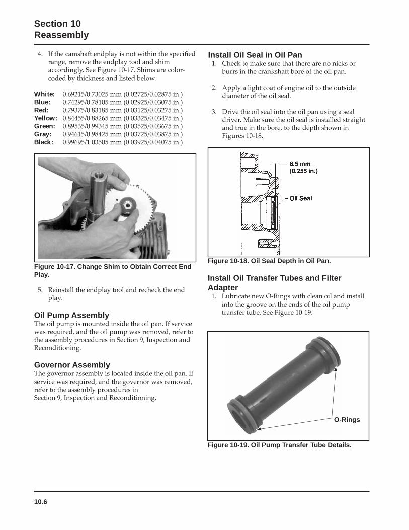
10.6
Section 10Reassembly
Figure 10-18. Oil Seal Depth in Oil Pan.
Install Oil Transfer Tubes and Filter Adapter
Figure 10-17. Change Shim to Obtain Correct End Play.
Oil Pump Assembly
Governor Assembly
White:Blue:Red:Yellow:Green:Gray:Black:
Figure 10-19. Oil Pump Transfer Tube Details.
O-Rings
Install Oil Seal in Oil Pan
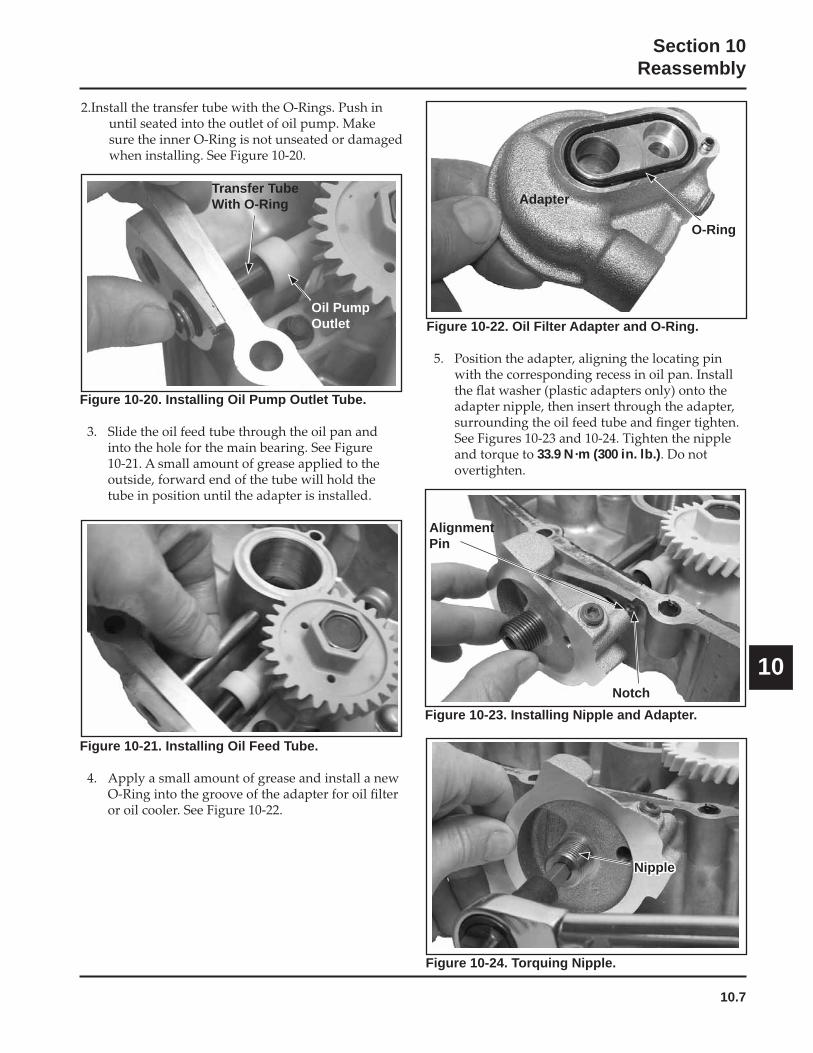
10.7
Section 10Reassembly
10
Figure 10-20. Installing Oil Pump Outlet Tube.
Figure 10-23. Installing Nipple and Adapter.
Figure 10-21. Installing Oil Feed Tube.
Transfer Tube With O-Ring
Oil Pump Outlet Figure 10-22. Oil Filter Adapter and O-Ring.
33.9 N·m (300 in. lb.)
Adapter
O-Ring
Figure 10-24. Torquing Nipple.
Nipple
AlignmentPin
Notch
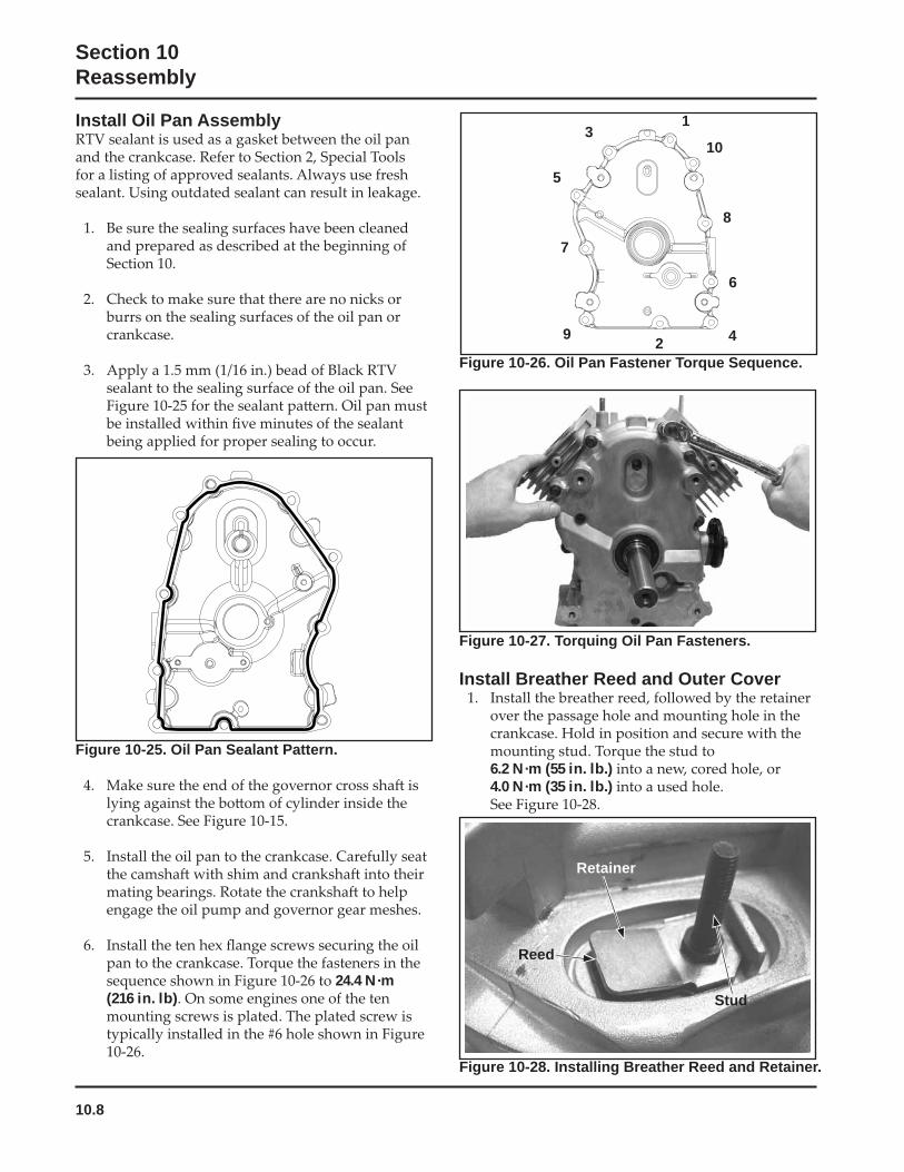
10.8
Section 10Reassembly
Figure 10-27. Torquing Oil Pan Fasteners.
Install Breather Reed and Outer Cover
6.2 N·m (55 in. lb.) 4.0 N·m (35 in. lb.)
Install Oil Pan Assembly
Figure 10-25. Oil Pan Sealant Pattern.
24.4 N·m (216 in. lb)
Figure 10-26. Oil Pan Fastener Torque Sequence.
1
10
8
6
429
7
5
3
Figure 10-28. Installing Breather Reed and Retainer.
Retainer
Reed
Stud
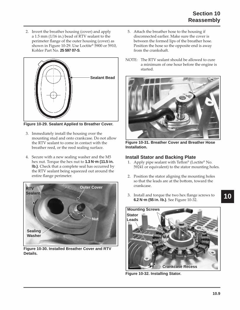
10.9
Section 10Reassembly
10
Figure 10-30. Installed Breather Cover and RTV Details.
Figure 10-29. Sealant Applied to Breather Cover.
1.3 N·m (11.5 in. lb.)
Figure 10-31. Breather Cover and Breather Hose Installation.
Install Stator and Backing Plate® ®
6.2 N·m (55 in. lb.)
Figure 10-32. Installing Stator.
®
25 597 07-S
Sealant Bead
RTVSealant
Outer Cover
SealingWasher
Nut
Mounting ScrewsStatorLeads
Crankcase Recess
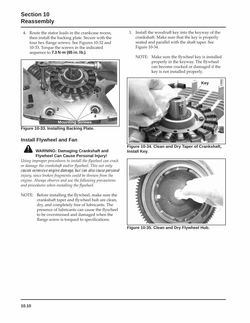
10.10
Section 10Reassembly
7.3 N·m (65 in. lb.)
Figure 10-33. Installing Backing Plate.
Install Flywheel and Fan
WARNING: Damaging Crankshaft and Flywheel Can Cause Personal Injury!
causes extensive engine damage, but can also cause personal
Figure 10-34. Clean and Dry Taper of Crankshaft, Install Key.
Mounting Screws
1
2
3
4
Key
Figure 10-35. Clean and Dry Flywheel Hub.
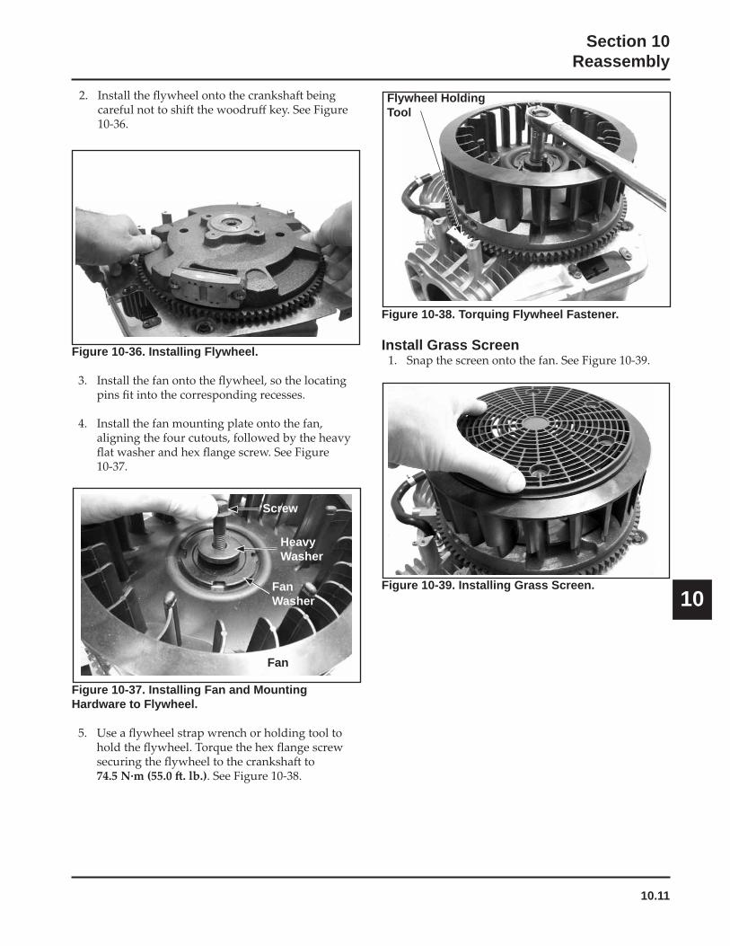
10.11
Section 10Reassembly
10
Figure 10-36. Installing Flywheel.
Figure 10-38. Torquing Flywheel Fastener.
Install Grass Screen
Figure 10-39. Installing Grass Screen.
Figure 10-37. Installing Fan and Mounting Hardware to Flywheel.
Screw
HeavyWasher
FanWasher
Fan
Flywheel Holding Tool
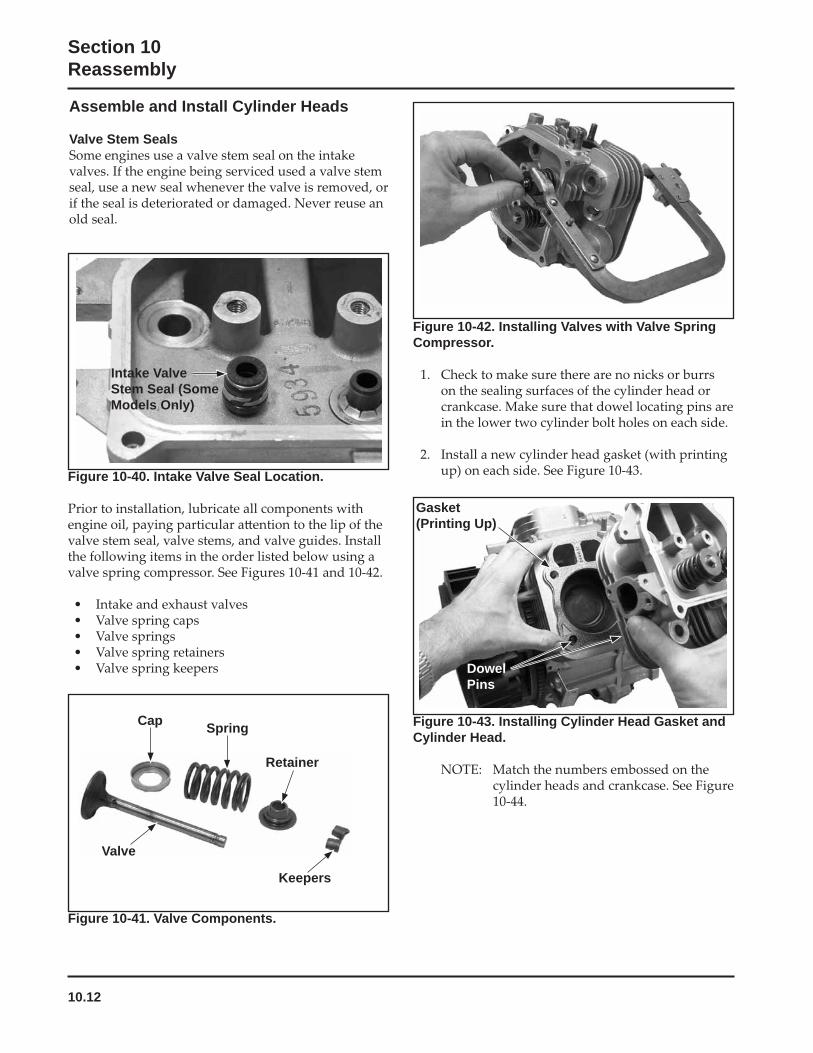
10.12
Section 10Reassembly
Figure 10-41. Valve Components.
Figure 10-43. Installing Cylinder Head Gasket and Cylinder Head.
Figure 10-40. Intake Valve Seal Location.
Intake Valve Stem Seal (Some Models Only)
Valve
Keepers
Retainer
SpringCap
Figure 10-42. Installing Valves with Valve Spring Compressor.
Gasket(Printing Up)
DowelPins
Assemble and Install Cylinder Heads
Valve Stem Seals
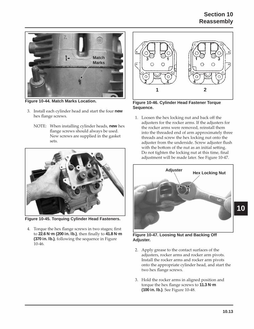
10.13
Section 10Reassembly
10
Figure 10-44. Match Marks Location.
new
new
Figure 10-47. Loosing Nut and Backing Off Adjuster.
11.3 N·m (100 in. lb.)
Figure 10-45. Torquing Cylinder Head Fasteners.
22.6 N·m (200 in. lb.) 41.8 N·m (370 in. lb.)
Figure 10-46. Cylinder Head Fastener Torque Sequence.
MatchMarks
1 2
Adjuster Hex Locking Nut
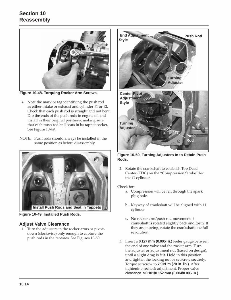
10.14
Section 10Reassembly
Figure 10-48. Torquing Rocker Arm Screws.
Figure 10-49. Installed Push Rods.
Adjust Valve Clearance
Install Push Rods and Seat in Tappets
Figure 10-50. Turning Adjusters In to Retain Push Rods.
0.127 mm (0.005 in.)
7.9 N·m (70 in. lb.)
clearance is 0.101/0.152 mm (0.004/0.006 in.)
PushRod
TurningAdjuster
End AdjustmentStyle
TurningAdjuster
Push Rod
Center PivotAdjustmentStyle
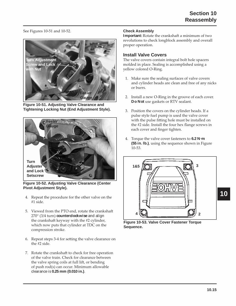
10.15
Section 10Reassembly
10
Check AssemblyImportant:
Install Valve Covers
Do Not
6.2 N·m (55 in. lb.)
Figure 10-53. Valve Cover Fastener Torque Sequence.
Figure 10-51. Adjusting Valve Clearance and Tightening Locking Nut (End Adjustment Style).
Figure 10-52. Adjusting Valve Clearance (Center Pivot Adjustment Style).
counterclockwise and align
clearance is 0.25 mm (0.010 in.)
FeelerGauge
TurnAdjusterand LockSetscrew
FeelerGauge
Turn AdjustmentScrew and Lockwith Nut
1&5 3
24
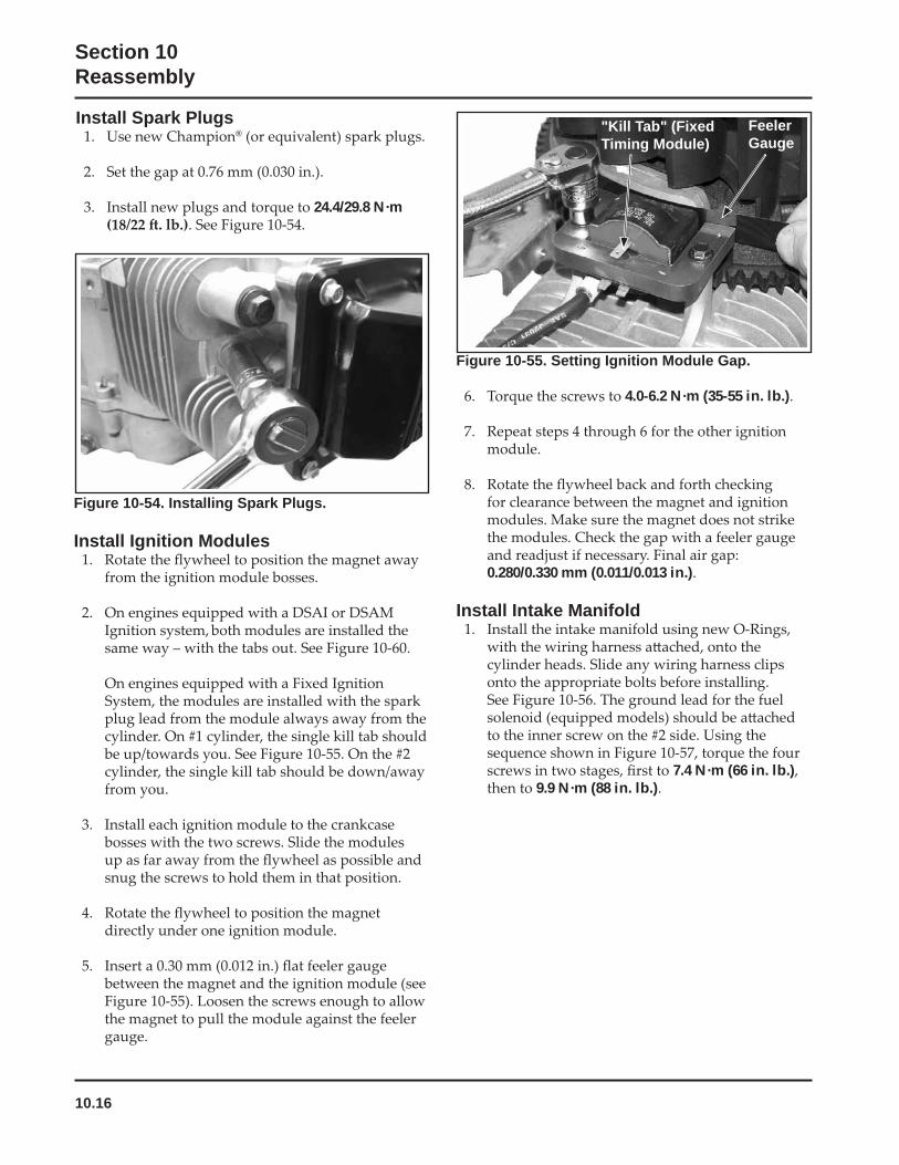
10.16
Section 10Reassembly
Figure 10-55. Setting Ignition Module Gap.
4.0-6.2 N·m (35-55 in. lb.)
0.280/0.330 mm (0.011/0.013 in.)
Install Intake Manifold
7.4 N·m (66 in. lb.)9.9 N·m (88 in. lb.)
"Kill Tab" (Fixed Timing Module)
FeelerGauge
Figure 10-54. Installing Spark Plugs.
Install Ignition Modules
Install Spark Plugs®
24.4/29.8 N·m
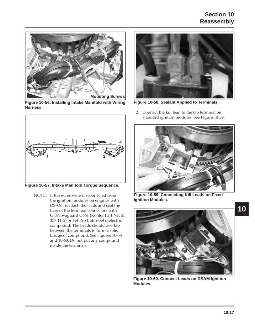
10.17
Section 10Reassembly
10
Figure 10-57. Intake Manifold Torque Sequence.
Clip
Mounting ScrewsFigure 10-56. Installing Intake Manifold with Wiring Harness.
1 2
3 4
Figure 10-58. Sealant Applied to Terminals.
Figure 10-59. Connecting Kill Leads on Fixed Ignition Modules.
Figure 10-60. Connect Leads on DSAM Ignition Modules.
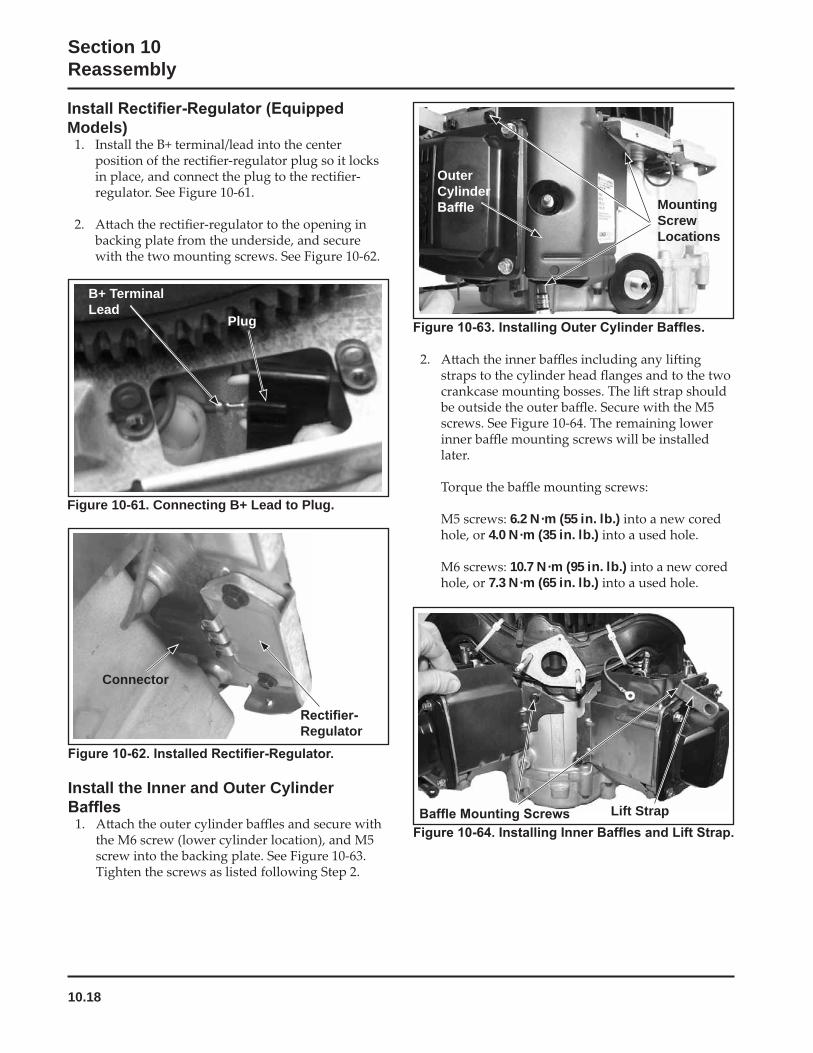
10.18
Section 10Reassembly
Install the Inner and Outer Cylinder
Connector
Regulator
6.2 N·m (55 in. lb.)4.0 N·m (35 in. lb.)
10.7 N·m (95 in. lb.)7.3 N·m (65 in. lb.)
OuterCylinder
MountingScrewLocations
Lift Strap
Models)
Figure 10-61. Connecting B+ Lead to Plug.
Plug
B+ Terminal Lead
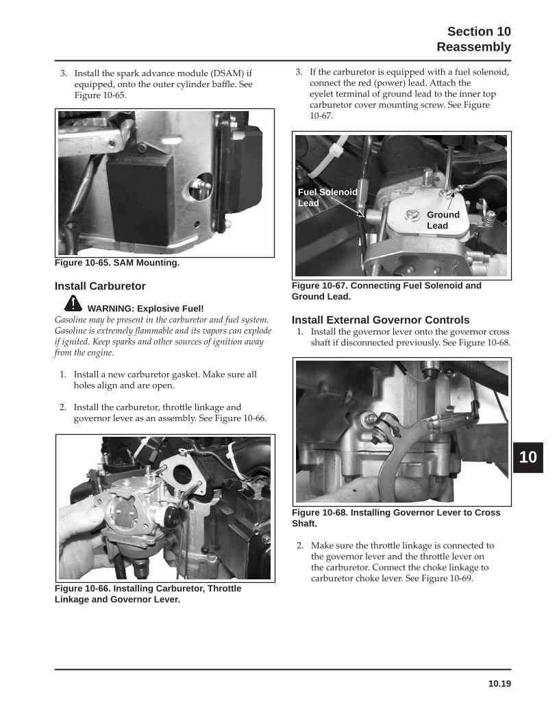
10.19
Section 10Reassembly
10
Figure 10-65. SAM Mounting.
Install Carburetor
WARNING: Explosive Fuel!
Figure 10-68. Installing Governor Lever to Cross Shaft.
Figure 10-67. Connecting Fuel Solenoid and Ground Lead.
Install External Governor Controls
Fuel Solenoid Lead
GroundLead
Figure 10-66. Installing Carburetor, Throttle Linkage and Governor Lever.
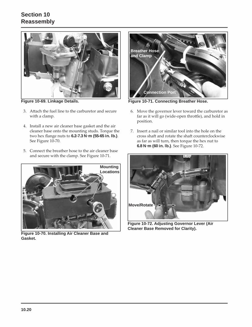
10.20
Section 10Reassembly
Figure 10-72. Adjusting Governor Lever (Air Cleaner Base Removed for Clarity).
Figure 10-71. Connecting Breather Hose.
6.8 N·m (60 in. lb.)
Connection Port
Breather Hose and Clamp
Move/Rotate
Figure 10-69. Linkage Details.
6.2-7.3 N·m (55-65 in. lb.)
Figure 10-70. Installing Air Cleaner Base and Gasket.
MountingLocations
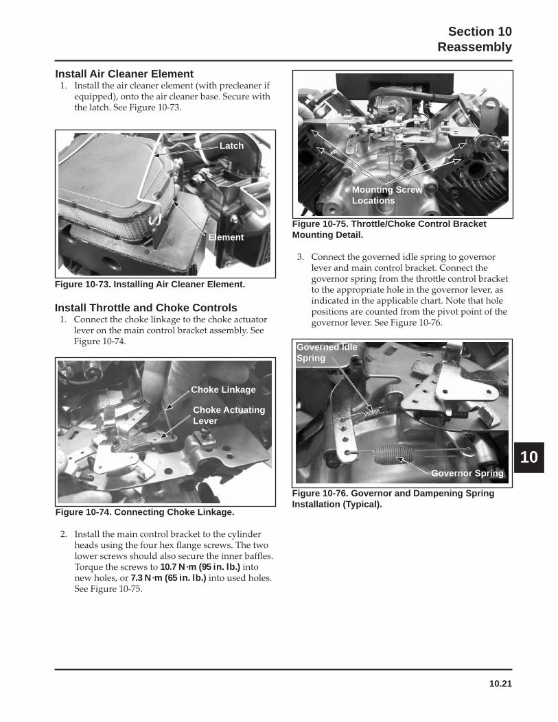
10.21
Section 10Reassembly
10
Figure 10-73. Installing Air Cleaner Element.
Install Throttle and Choke Controls
Figure 10-74. Connecting Choke Linkage.
10.7 N·m (95 in. lb.)7.3 N·m (65 in. lb.)
Latch
Choke Linkage
Element
Choke Actuating Lever
Figure 10-76. Governor and Dampening Spring Installation (Typical).
Figure 10-75. Throttle/Choke Control Bracket Mounting Detail.
Mounting Screw Locations
Governed Idle Spring
Governor Spring
Install Air Cleaner Element
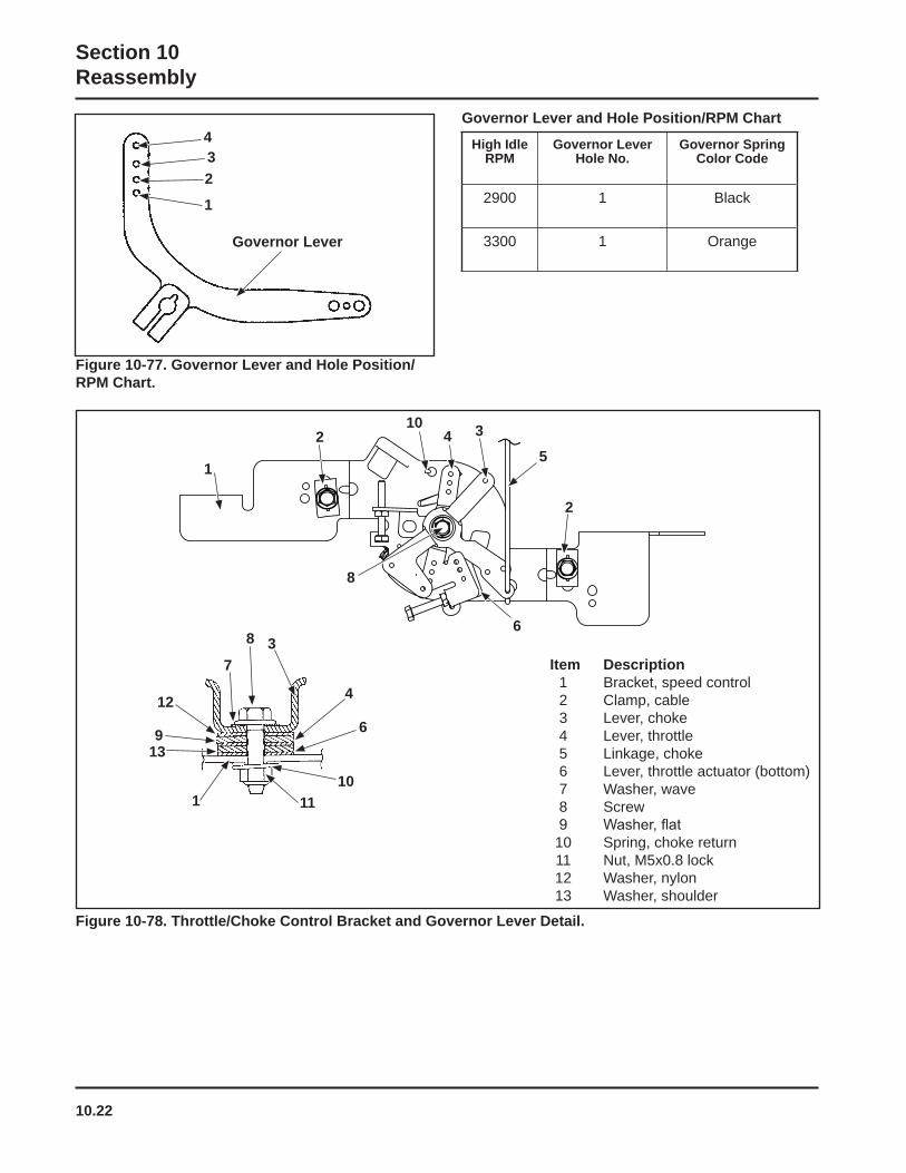
10.22
Section 10Reassembly
Item Description 1 Bracket, speed control 2 Clamp, cable 3 Lever, choke 4 Lever, throttle 5 Linkage, choke 6 Lever, throttle actuator (bottom) 7 Washer, wave 8 Screw
10 Spring, choke return 11 Nut, M5x0.8 lock 12 Washer, nylon 13 Washer, shoulder
1
2 345
6
8
10
9
8
6
3
4
110
11
Figure 10-78. Throttle/Choke Control Bracket and Governor Lever Detail.
2
13
12
7
1
234
Governor Lever
High Idle RPM
Governor Lever Hole No.
Governor Spring Color Code
2900 1 Black
3300 1 Orange
Governor Lever and Hole Position/RPM Chart
Figure 10-77. Governor Lever and Hole Position/RPM Chart.
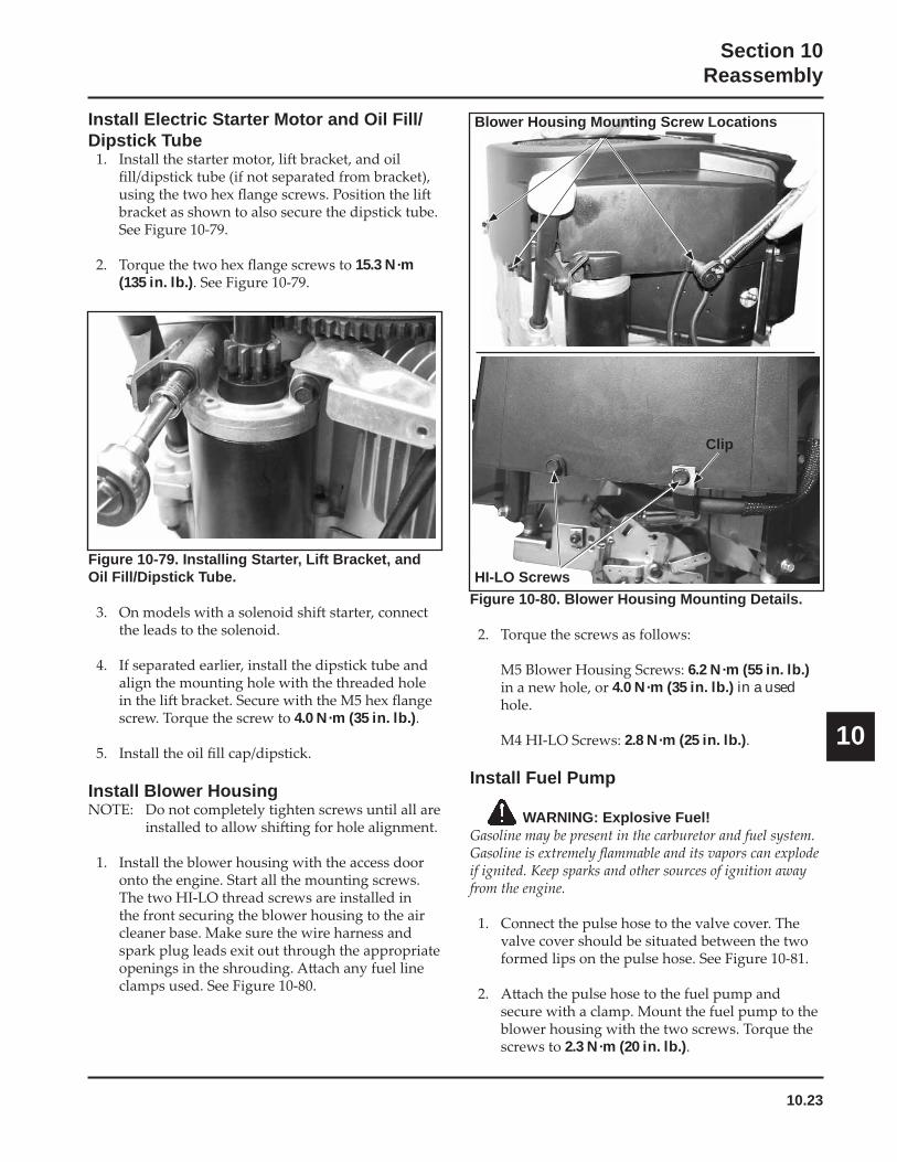
10.23
Section 10Reassembly
10
Figure 10-79. Installing Starter, Lift Bracket, and Oil Fill/Dipstick Tube.
4.0 N·m (35 in. lb.)
Install Blower Housing
Figure 10-80. Blower Housing Mounting Details.
6.2 N·m (55 in. lb.)4.0 N·m (35 in. lb.) in a used
2.8 N·m (25 in. lb.)
Install Fuel Pump
WARNING: Explosive Fuel!
2.3 N·m (20 in. lb.)
Install Electric Starter Motor and Oil Fill/Dipstick Tube
15.3 N·m (135 in. lb.)
Blower Housing Mounting Screw Locations
HI-LO Screws
Clip
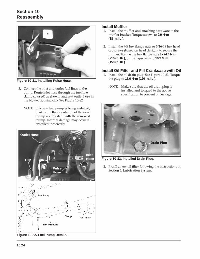
10.24
Section 10Reassembly
Figure 10-81. Installing Pulse Hose.
Figure 10-82. Fuel Pump Details.
9.9 N·m (88 in. lb.)
24.4 N·m (216 in. lb.), 16.9 N·m (150 in. lb.).
Install Oil Filter and Fill Crankcase with Oil
13.6 N·m (120 in. lb.)
Figure 10-83. Installed Drain Plug.
Outlet Hose
PulseHose
InletHoseClip
Drain Plug
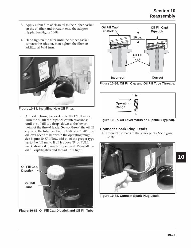
10.25
Section 10Reassembly
10
Figure 10-84. Installing New Oil Filter.
Do not
Figure 10-85. Oil Fill Cap/Dipstick and Oil Fill Tube.
Figure 10-88. Connect Spark Plug Leads.
Connect Spark Plug Leads
Oil FillTube
Oil Fill Cap/Dipstick
Figure 10-86. Oil Fill Cap and Oil Fill Tube Threads.
10 oz.
Incorrect Correct
Oil Fill Cap/Dipstick
Oil Fill Cap/Dipstick
Oil FillTube
Figure 10-87. Oil Level Marks on Dipstick (Typical).
OperatingRange
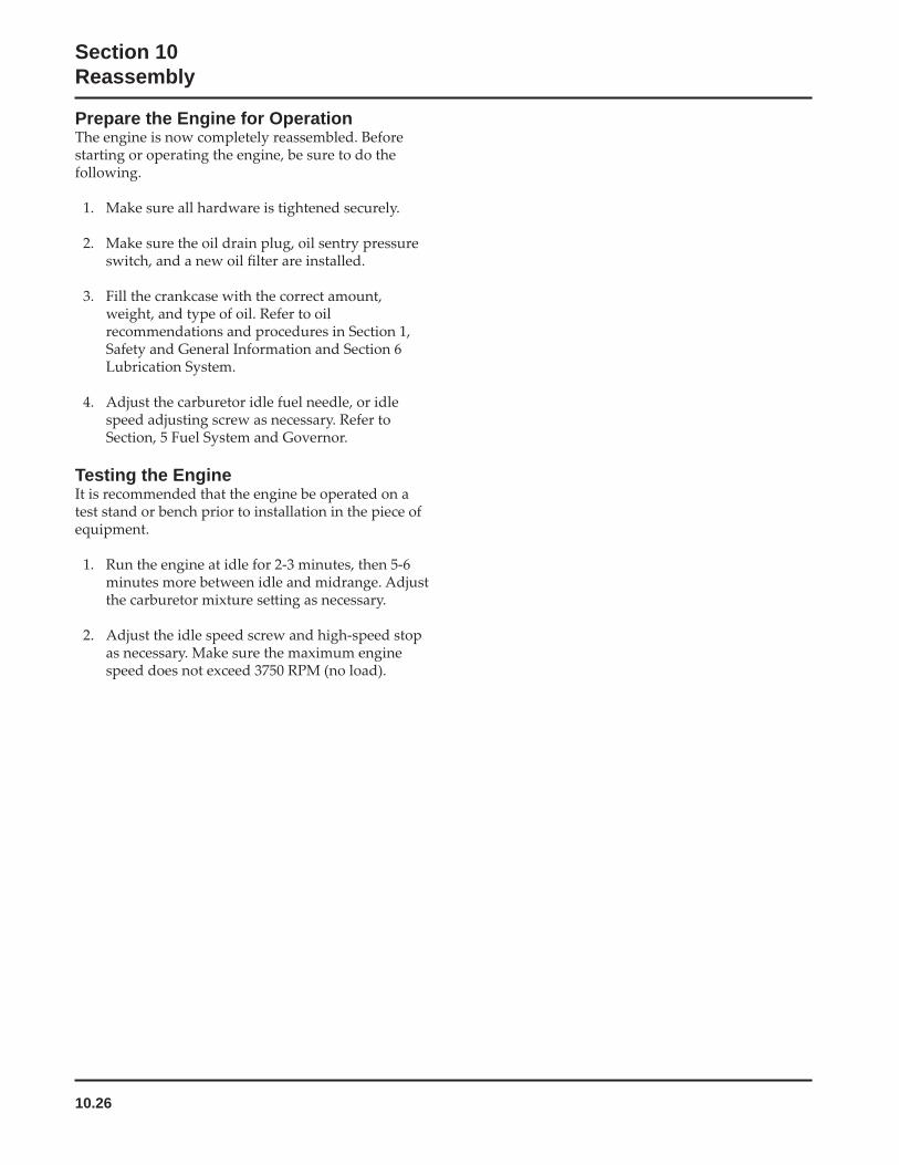
10.26
Section 10Reassembly
Prepare the Engine for Operation
Testing the Engine
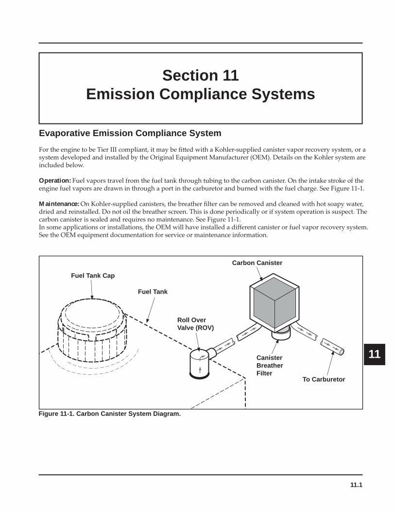
11.1
Section 11Emission Compliance Systems
11
Section 11Emission Compliance Systems
Evaporative Emission Compliance System
Operation:
Maintenance:
Fuel Tank
Roll Over Valve (ROV)
Carbon Canister
CanisterBreatherFilter
To Carburetor
Figure 11-1. Carbon Canister System Diagram.
Fuel Tank Cap
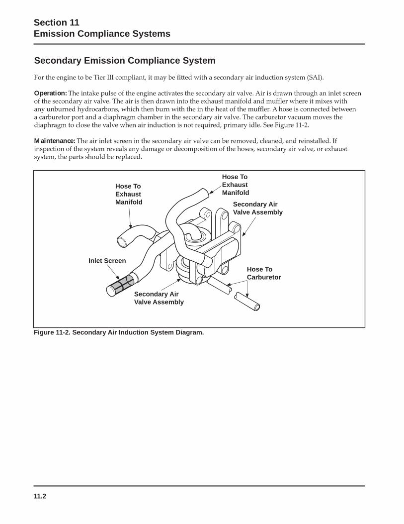
11.2
Section 11Emission Compliance Systems
Figure 11-2. Secondary Air Induction System Diagram.
Hose To Carburetor
Inlet Screen
Hose To ExhaustManifold
Hose To ExhaustManifold
Secondary Air Valve Assembly
Secondary Emission Compliance System
Operation:
Maintenance:
Secondary Air Valve Assembly


LITHO IN U.S.A.
FORM NO.: TP-2574-AISSUED: 1/06REVISED: 12/07
ENGINE DIVISION, KOHLER CO., KOHLER, WISCONSIN 53044
FOR SALES AND SERVICE INFORMATION IN U.S. AND CANADA, CALL 1-800-544-2444
KohlerEngines.com