lh2 airport requirements study - nasa
TRANSCRIPT

.. . . . . . . ..
N A S A
0 0 h cy
cy U
I
C O N T R A
R E P O R T
C T O R
4 m U z
LH2 AIRPORT REQUIREMENTS STUDY
TECH LIBRARY U F B , NM
0061437 1. REPORT NO. '2. GOVERNMENT ACCESSION NO. 3. REClI'lkN r'S CATALOG NO.
NASA CR-2700 4. TITLE AND SUBTITLE 5. REPORT DATE
LHz AIRPORT REQUIREMENTS STUDY October 1976
6. PERFORMING ORG CODE
7. AUTHOR(S) 8. PERFORMING ORG REPORT NO.
G. D. Brewer - Edi tor LR 27581 . _
0. WORK UNIT NO. 9. PERFORMING ORGANIZATION NAME AND ADDRESS
I LOCKHEED-CALIFORNIA COMPANY P.O. BOX 551 BURBANK, CALIFORNIA 91520 NAS 1-14137
13. TYPE OF REPORT.AND PERIOD 12. SPONSORING AGENCY NAME AND ADDRESS CovEREDContractor Fina
National Aeronautics and Space Administration 14. SPONSORING AGENCY CODE Langley Research Center Fepor t ; Sep 1975-Feb 197(
"
Hampton, V i rg in i a 23665 I Langley Technical Monitor: Peter F. Korycinski
15. SUPPLEMENTARY NOTES
Fina l PeDort 16. ABSTRACT
This study w a s performed to p rov ide a preliminary assessment of t h e f a c i l i t i e s and equipment which w i l l be required a t a r e p r e s e n t a t i v e a i r p o r t so l i q u i d hydrogen (LH ) can be used a s f u e l i n l o n g r a n g e t r a n s p o r t a i r c r a f t i n 1995-2000.
2
Using San F ranc i sco In t e rna t iona l a i rpo r t as a b a s i s f o r t h e a n a l y s i s , a complete f a c i l i t y w a s conceptua l ly des igned , s ized to meet the p ro j ec t ed a i r t ra f f ic requi rement . The f a c i l i t y i n c l u d e s t h e l i q u e f a c t i o n p l a n t , LH2 storagl capab i l i t y , and LH2 fuel handling system. I n addi t ion , the requi rements for ground support and maintenance for the LH2 f u e l e d a i r c r a f t were analyzed. An est imate was made of c a p i t a l and operating costs which might be expected for t h e f a c i l i t y . F i n a l l y , recommendations were made for des ign modi f ica t ions to t h e , r e f e r e n c e a i r c r a f t , r e f l e c t i n g r e s u l t s o f t h e a n a l y s i s of a i r p o r t f u e l handling requirements, and for a program of additional technology development fo r air terminal-related items.
17. KEY WORDS (SUGGESTED BY AUTHOR(S) ) 18. DISTRIBUTION STATEMENT
Hydrogen, a i r p o r t fuel system, LH2 l ique fac t ion , LH2 s to rage , air terminal operations, cryogenic, subsonic t r anspor t aircraft
Unclassif ied - Unlimited
Subiect C a t v 0 3 19. SECURITY CLASSIF.
(OF THIS REPORT) 20. SECURITY CLASSIF. (OF THIS PAGE) 21. NO. OF PA%22. PRICE'
. Unclassif ied $7.00 199 Unclassif ied
For sale by the National Technical Information Service, Springfield, Virginia 22161


FOREWORD
The Lockheed-California Company w a s the pr ime cont rac tor to NASA and the s tudy w a s accomplished within the Advanced Design Division of t h e Science and Technology organization, Burbank, California . G. Daniel Brewer was study manager and Robert E. Morris w a s project engineer .
Important segments of the work were subcontracted to the following organizat ions t o provide the highest technical competence in all aspec ts of the s tudy. The ind iv idua ls named were pr inc ip le cont r ibu tors .
Ralph M. Parsons Co-. (Airport and f a c i l i t i e s p l a n n i n g ) Jack Hoyt .Jon B a t i s t i c Richard Cline
Linde Division - Union Carbide Corporation (Hydrogen l iquefac t ion and s torage)
Richard Shaner Charles Baker Richard Carney
IJnited Airlines (Aircraft maintenmce and ground support) Ralph Cramer Paul Campbell
All computations in this analysis were performed i n U . S . Customary units and then converted to SI units.
iii


CONTENTS
Section Page
FOREWORD ................................................... iii LIST OF FIGURES ............................................ ix
LIST OF TABLES ............................................. xi
SUMMARY .................................................... 1
4
INTRODUCTION ............................................... 5
TECHNICAL APPROACH ......................................... 6
PHASE I . DEFINITION OF THE AIRPORT LH2 REQUIREMENTS ....... 8
3.1 Task 1: Airport Selection ............................ 8 3.2 Task 2: Traffic and Fuel Requirements ................ 10
3.2.1 Implementation Timetable ....................... 10 3.2.2 Projection of LH2 requirement at SF0 ........... 19 3.2.3 Airport fueling facility design flow rate ...... 29 3.2.4 Data summary ................................... 31
PHASE I1 . DESIGN AND EVALUATION OF SYSTEM ELEMENTS ........ 31
4.1.1 Evaluation of distribution system losses ....... 33 4.1.2 Hydrogen gas pipeline .......................... 34 4.1.3 Vacuum jacketed pipeline ....................... 34 4.1.4 Truck-trailer transport ........................ 39 4.1.5 Tank car transport ............................. 41 4.1.6 Comparison of transport methods ................ 41 4.1.7 Economic analysis for present value ............ 45
4.2 Task 4: Fueling Operations .......................... 48
4.2.1 Program and plans at SF0 ...................... 49
4.2.3 Hazard criteria ................................ 50 4.2.2 Operational objectives ......................... 50
4.2.4 Candidate loading procedures ................... 52
V

Section
CONTENTS (Continued)
4.2.5 Evaluation of external tank aircraft concept ...................................... 60
4-.2.6 System description ............................. 60
4.3 Task 5: Hydrogen Storage Evaluation .................. 64 4.3.1 Tanklfarm requirements ......................... 64 4.3.2 Underground vs aboveground tanks ............... 65 4.3.3 Vacuum insulated double wall tanks ............ 66 4.3,4 Insulated'single wall tanks .................... 67 4.3.5 Economic comparison ............................ 68
4.4 Task 6: Hydrogen Liquefaction ........................ 69
4.4.1 4.4.2 4.4.3 4.4.4 4.4.5 4.4.6 4.4.7 4.4.8 4.4.9
Liquefaction facility requirements ............. 73 Liquefaction facility description .............. 73 Layout of liquefaction facility ................ 80 Single module liquefaction layout .............. 81 Safety considerations .......................... 81 Gaseous hydrogen vent collection system ........ 81 Utilities ....................................... 83 costs .......................................... 83 Personnel requirements ......................... 83
4.5 Task 7 : Airport Fuel Distribution System . . . . 0 83
4.5.1 4.5.2 4.5.3 4.5.4 4.5.5 4.5.6 4.5.7 4.5.8 4.5.9
Fueling system description ..................... 89 Ground distribution and refueling system ....... 9 LH2 transfer method ............................ 95 Vent gas disposition ........................... 102 Defueling/refueling for aircraft maintenance ... 103 System reliability and availability ............ 106 Instrumentation ................................ 107 System arrangement/installation concept ........ 108 Hazards analysis ............................... 111
4.6 Task 8: Aircraft Maintenance Requirements ............ 113
4.6.1 Changing of line replaceable units (LRUS) ....... 113 4.6.2 Inspection. maintenance and repair of tank
and insulation systems ........................ 115 4.6.3 Handling of hydrogen aircraft in a
maintenance hangar ............................ 116 4.6.4 Maintenance facility ............................ 116
vi

Section
CONTENTS (Continued)
5
4.6.5 Line maintenance station at SF0 ............... 118 4.6.6 Impact of hydrogen on normal routine
maintenance of other aircraft systems and equipment ............................... 118
4.7 Task 9 : Airline Ground Support Requirements ......... 1x9 4.7.1 Facility and equipment requirements ........... 124 4.7.2 Special equipment required for LH2 aircraft ... 126 4.7.3 Effect of aircraft configuration on
maintenance and support requirements ........ 127 PHASE I11 . CONCEPT DESCRIPTIOX ........................... 128
5.1 Task 10: Concept Arrangement and Description ........ 128 5.1.1 Description of selected concept ............... 128 5.1.2 Summary of cost implications .................. 137 5.1.3 Special facilities and equipment .............. 146
5.2 Task 11: Suggested Changes in LH2 Aircraft .......... 152 RECOMMENDED RESEARCH AND TECHNOLOGY DEVELOPMENT ........... 154 CONCLUSIONS ............................................... 158
RECOMMENDATIONS ........................................... 161
APPENDIX A . HYDROGEN SUPPLY METHODS ...................... 163
APPENDIX B . SAFETY CONSIDERATIONS ......................... 179
REFERENCES ................................................. 189 . . .
vi i

Figure No . LIST OF FIGURES
Page
5
6 7 8 9
10
11
12
13
14 1 5 16
17 18
19 20
21
22
Work Flow chart ............................................. 7 Typical. LH2-Fueled Subsonic-Transport Aircraft ............... g Three-View of Internal-Tank. 5500 n .m i. Subsonic Transport ... 11 Aerial Photo of San Francisco International Airport .......... 15 Schedule for Operational Development of LH2 Transport A i r c r a f t ..................................................... 17 San Francisco Hub Airport Traff ic Forecast ................... 20
Ten Airpor t s Pro jec ted for I n i t i a l LH2 F a c i l i t i e s ............ 23
Schedule for Construction of Airport Hydrogen F a c i l i t i e s ..... 28
Tota l Quant i ty o f LH2 Loaded p e r Year at SF0 ................. 30
Total Cost of Gaseous Hydrogen Pipe l ine ...................... 38 Total Cost of Transporting Hydrogen Gas and Liquid vs Liquefier Distance from Airport .............................. 43 Cost for Liquid Hydrogen Transport Over 16.1 km (10 mile) Distance ..................................................... 44 San Francisco Internat ional Airport 1985 Plan .................................................... 53 Comparison of Al te rna te Ground Handling Procedures ........... 56 LH2 Gate Requirements ........................................ 57 Gate with LH2 Service ........................................ 61 LH -H Fueling-Truck Concept ............................ 63 2 y Cost of Spherical Double Wall Vacuum P e r l i t e I n s u l a t e d Liquid Hydrogen Storage T a n k s ................................ 70 Cost of Three Types of Liquid Hydrogen Storage Tanks ......... 72
Block Diagram - Liquefaction Process ......................... 74 Proposed Hydrogen Liquefaction/Storage Facility San Francisco In te rna t iona l Ai rpor t .............................. 75 Plant Layout - 250 TPD Hydrogen Liquefaction Module .......... 82
i x

Figure No . LIST OF FIGURES (Continued)
Page
23
24
25
26
28 27
29
30
31
32
33
34 35 36
37
Typical Hydrant Pit ......................................... 90 Hydrant Fueling Schematic ................................... 93 Dis t r ibu t ion System Schematic ............................... 97 Dis t r ibu t ion System Schematic ............................... 99 Dis t r ibu t ion Loop Concept Plan .............................. 101
Typical Liquid Hydrogen Trench .............................. 110
Terminal Operations: Through-Stop 650 Nautical Mile Stage Length ................................................ 121
Stage Length ................................................ 122
Terminal Servicing Equipment fo r Cur ren t J e t A-Fueled Aircraf t ........................................... 123
LH2 F a c i l i t y I n s t a l l a t i o n f o r SF0 ........................... 131 LH2 Dis t r ibu t ion System and Gate Pos i t ions a t SF0 ........... 133 Apron Taxilane Clearances (South) ........................... 135 Apron Taxilane Clearances (North) ........................... 136 Ef fec t of E l e c t r i c Power and Hydrogen Gas Feedstock Costs on Unit Cost of L€$ ......................................... 144
Terminal Operations: Turnaround Station 5000 Naut ical Mile
Aircraf t LH2 Fuel System Schematic .......................... '55
X

Table
I I1 I11
IV v VI
VI1
VI11
IX X
XI
XI1
XI11
XIV xv
XVI
XVII
XVIII
XIX
xx
LIST OF T m @ S
Page
Preliminary Airport Screening .............................. Final Airport Selection ..................................... Assumptions and Guidelines - LH2 Aircraft Traffic Forecast .................................................
Projection of Total Enplanements to 2000 A.D. ............... Projected Total Fuel Loaded - LH2-Aircraft at.SFO ........... Summary of LH2 Loaded at SF0 - 2000 A.D ..................... Airline Destinations. Departure Times and LH2 System Flow Rates ................................................
LH2 Boi lof f Losses and Production Requirements f o r Various Supply Methods .................................. Summary of Vehicle Operations ............................... Total Cost (Present Value) of Gaseous HydrogeQ Pipeline ..... Total Cost (Present Value) of Transmitting Liquid Hydrogen via Vacuum Jacketed Pipeline .............................
Total Cost (Present Value) of Transporting Liquid Hydrogen via Truck-Trailer (Tank Method No . 1) .....................
Total Cost (Present Value) of Transporting Liquid Hydrogen via Railroad Tank Car (Tank Method No . 1) ................
Assumptions for Economic Analysis .......................... Specifications: Liquid Hydrogen Storage Tank Vacuum Powder Insulation ........................................
Specifications: Liquid Hydrogen Storage Tank Multilayer Insulation ...............................................
Specifications: Liquid Hydrogen Storage Tank Single Wall - Foam Insulation ....................................
Economic Comparison Liquid ISydrogen Storage Tanks .......... Storage Complex San Francisco International Airport ....... San Francisco International Airport .......................
Equipment List of Major Items: Hydrogen Liquefaction/
Utility Summary: Hydrogen Liquefaction/Storage Complex.
13 14
21
25
26 27
32
35 36 37
39
40
42
47
66
67
68
71
78
84
xi
.

. . . . I .111 1 1 1 1 1 1 1 . . . . . . . . . . . . . . . . . .
LIST OF TABLES (Continued)
Table Page
XXI Capital Investment: Hydrogen Liquefaction/Storage
XXII Annual Operating Cost: Hydrogen Liquefaction/Storage
XXIII Cost Assumptions: Hydrogen Liquefaction/Storage Complex, San Francisco International Airport ....................... 88
XXIV Summary of Investment and Operating Costs 142 xxv Base Cost of Liquid Hydrogen at SF0 145
Complex, San Francisco International Airport .............. 86
Complex, San Francisco International Airport .............. 87
................... .........................
xii
LH2 AIRPORT FEQUIREMENTS STUDY
G. D. Brewer , Edi tor Lockheed-California Company
Burbank, Cal i forn ia
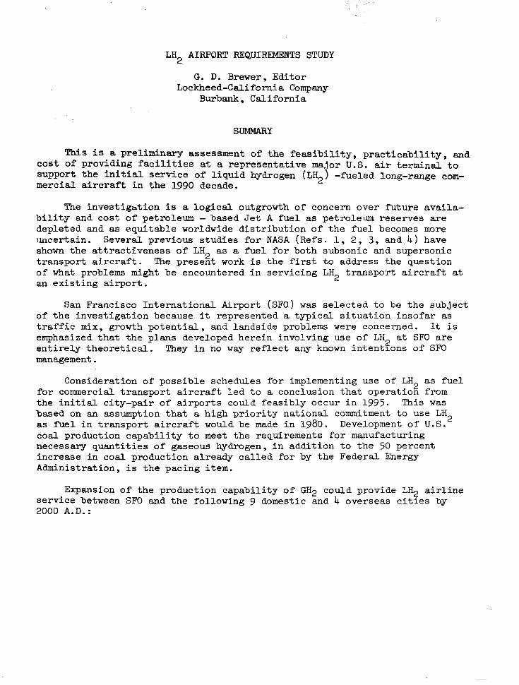
This is a preliminary assessment of t h e f e a s i b i l i t y , p r a c t i c a b i l i t y , and cos t o f p rov id ing f ac i l i t i e s at a representat ive major U.S. a i r t e r m i n a l t o s u p p o r t t h e i n i t i a l s e r v i c e o f l i q u i d hydrogen (LH2) -fueled long-range com- m e r c i a l a i r c r a f t i n t h e 1990 decade.
"he inves t iga t ion is a logical outgrowth of concern over future availa- b i l i t y and cost of petroleum - based Jet A f u e l as petroleum reserves are depleted and as equitable worldwide distribution of the fuel becomes more uncertain. Several previous s tudies for NASA (Refs. I , 2 , 3, and. 4 ) have shown the a t t r ac t iveness o f LH as a fuel for both subsonic and supersonic t r a n s p o r t a i r c r a f t . The present work i s t h e first to address the quest ion of what problems might be encountered i n se rv ic ing LH t r a n s p o r t a i r c r a f t at an e x i s t i n g a i r p o r t .
2
2
San Francisco Internat ional Airport (SFO) was s e l e c t e d t o be the subjec t of the invest igat ion because it represented a t y p i c a l s i t u a t i o n i n s o f a r as t r a f f i c mix, growth p o t e n t i a l , and landside problems were concerned. It i s emphasized that the plans developed herein involving use of LB a t SF0 a re e n t i r e l y t h e o r e t i c a l . They i n no way r e f l e c t any known in ten t lons o f SF0 management.
2
Consideration of possible schedules for implementing use of LH as f u e l f o r commercial t r a n s p o r t a i r c r a f t l e d t o a conclusion that operat ion from t h e i n i t i a l c i t y - p a i r of a i rports could feasibly occur i n 1995. This w a s based on an assumption t h a t a h i g h p r i o r i t y n a t i o n a l commitment to use LH as f u e l i n t r a n s p o r t a i r c r a f t would be made i n 1980. Development of U . S . coa l p roduct ion capabi l i ty to meet the requirements for manufacturing necessary quant i t ies of gaseous hydrogen, in addi t ion to the 50 percent increase in coal product ion a l ready cal led for by the Federal Energy Administration, i s the pac ing i t e m .
2
2
Expansion of the production capabili ty of GH2 could provide L% a i r l ine service between SF0 and the following 9 domestic and 4 o v e r s e a s c i t i e s by 2000 A.D.:

Domestic
Chicago Honolulu New York Dallas - Ft. Worth Atlanta Washington M i ami Kansas Ci ty Los Angeles
ORD HNL JFK DFW ATL IAD MIA M C I LAX
F1 i gh t s /day
14 10
9 9 3 3 2 2 7
Overseas Fl ights /day
Tokyo TYO 5 London LHR 3 Paris CDG 2 Rome FCO 1
The number of f l i g h t s p e r day from SF0 l i s t e d i n t h e t a b l e is pos tu la ted for an average day i n t h e peak month i n 2000 A.D. This maximum schedule requi res 663,163 kg of LH for b lock fue l use . Accounting f o r GH bo i lo f f which occur s i n s to rage , r e fue l ing ope ra t ions , and a i r c r a f t o p e r a i o n s , an add i t iona l 15.7 percent o f l iquefac t ion capac i ty must be provided, making t h e t o t a l for the average day i n t h e peak month 767,491 kg. Of t h i s 15.7 pe rcen t bo i lo f f , 91.5 percent can be recovered, p iped back to the l iquefact ion p l a n t , and both the gas and i t s refr igerat ion energy recovered. Most o f t he 1.35 p e r c e n t o f t h e t o t a l LH2 produced which cannot be recovered i s t h a t por t ion which i s ,vented i n f l i g h t t o a v o i d o v e r p r e s s u r i z a t i o n o f t h e a i r c r a f t tanks .
2 z
The preferred arrangement of LH f a c i l i t i e s f o r SF0 p laces t he hydrogen l i que fac t ion p l an t and LH s torage t anks in a current ly unused area on t h e 2
south s ide of the seaplane harbor (see Figure 1 3 ) . A small a rea o f the bas in would r e q u i r e l a n d f i l l , and a causeway ac ross t he en t r ance t o t he bas in would provide a convenient access route for the gaseous hydrogen (GH ) p i p e l i n e , e l e c t r i c power t r a n s m i s s i o n l i n e , and a road for operating and maintenance se rv ices . The f a c i l i t y i s en t i re ly wi th in p resent boundar ies o f the a i rpor t .
2
2
Four 226,800 kg/day l i que fac t ion p l an t modules are planned, providing an 18 percent excess for reserve capacity and growth potential . Based on l iquefaction technology presumed f o r 1985 ' s t a t e o f t h e ar t , 332 MW o f e l e c t r i c power w i l l be required. It i s f e l t t h i s requirement can be reduced when a m r e comprehensive systems analysis of the facil i ty i s performed.
Five spherical tanks, each 21.5 n ' i n diameter, w i l l provide s torage of a t o t a l o f 18 900 m 3 ( 5 x lo6 ga l lons ) of LH2. During operation, one tank would be pumped out of to supply LH t o t h e f u e l i n g c i r c u i t ; one tank would be pumped in to , bo th from the fue l lng c i r cu i t r e tu rn and a l so from the l i que fac t ion p l an t ou tpu t ; and the o the r t h ree t anks a r e r e se rve . A t l e a s t one peak-day reserve i s ava i l ab le a t a l l t imes in the event feedstock supply (gaseous hydrogen) i s in te r rupted .
2
LH2 i s pumped from the s torage tanks through vacuum jacke ted p ipes in two independent loops around the entire terminal area to provide an instantaneous supply a t any of t h e 19 ga te pos i t i ons which are r e q u i r e d t o
2

meet pro jec ted long range t ra f f ic demands. The L% supply lines., and a GH2 boi lof f recovery l ine , are l o c a t e d i n a trench covered by an open steel g ra t e fo r r eady access ib i l i t y and t o eliminate accumulation of hydrogen gas i n t h e poss ib le event o f l ine l eakage or rup ture .
Analysis showed t h a t LH2 a i r c r a f t c a n be serv iced at air terminal gates in essent ia l ly convent iona l fash ion . Time r e q u i r e d t o refuel an LH2 a i rp l ane , and t o perform a l l o the r s e rv i c ing func t ions fo r e i t he r a through-flight o r . a turnaround, can be the same as f o r an equivalent Jet A-fueled a i r c r a f t . The only differences are tha t fo r t he L%-fue led a i r c ra f t r e fue l ing is done at a s i n g l e p o i n t i n t h e t a i l cone of the fuselage instead of at separa te connections under both wings; the f l ight crew must be provided a separate a c c e s s t o t h e f l i g h t s t a t i o n b e c a u s e t h e s u b j e c t a i r c r a f t h a s no passageway between the passenger compartment and the cockpi t ; and, a t least i n i t i a l l y , un t i l po ten t i a l haza rds are more r ea l i s t i ca l ly app ra i sed , spa rk i gn i t i on vehicles may be excluded from an area 27.4 m i n r a d i u s from t h e t a i l cone while fuel ing i s in p rogress . In addi t ion , a s l i gh t pos i t i ve p re s su re may be requi red wi th in the a i rc raf t dur ing fue l ing to p revent ingress o f .gaseous hydrogen i n the event o f a l e a k o r s p i l l o f LH2. More de ta i led s tudy of the safety aspects of the fuel ing procedures has been recommended to determine i f t h e s e r e s t r i c t i o n s are necessary.
LH2-fueled a i r c r a f t w i l l keep fuel i n t h e i r t a n k s a t all times, except when they are scheduled to be out of service for extended per iods, e .g . , mre than 7 days, and when t h e tanks must be en te red for inspec t ion or maintenance. This minimizes thermal cycl ing of t he t ank s t ruc tu re and insulation system, and also el iminates undue delays and expense which would otherwise be involved in cooling down the tank/insulation system when t h e a i r c r a f t i s prepared for i t s next f l ight . Since cold GH2 which i s boiled- off during out-of-service periods i s recovered and reliquefied, the p rac t i ce of keeping LH i n t h e t a n k s at a l l times i s c l ea r ly cos t e f f ec t ive . 2
It is a n t i c i p a t e d t h a t when LH2 a i r c r a f t a r e i n i t i a l l y p l a c e d i n s e rv i ce , inspect ion of t h e i r f u e l t a n k s w i l l be required approximately once a year (a f te r about 4000 h r o f s e rv i ce ) . The procedures for defueling LH2 a i r c r a f t t o perform this inspect ion, and for the subsequent refuel ing, are qui te t ime consuming and involved. Defueling consists of pumping out the fue l us ing the a i r c ra f t boos t pumps, i n e r t i n g , warmup, and flooding with a i r to permi t entry. Refueling involves removal of the a i r , purif icat ion, and chi l ldown before the fuel can be pumped back i n . The ent i re procedure is e s t ima ted t o take from 6 t o 18 hours.depending on d e t a i l s o f t h e s i t u a t i o n . A spec ia l a r ea for these defue l / re fue l opera t ions i s provided ad jacent to the l iquefac t ion p lan t .
3

111 I1111111111 .I1 111 I I I I I I I 11111 1 1 1 1 1 1 1
Estimated capi ta l cost of t h e SF0 LH f a c i l i t y is summarized as 2 follows :
$lo6
I Liquefact ion/s torage plant 308.6
Distr ibut ion system 0 Trench construction 5.8
I 0 Piping/v&ves , e t c . 25.6
Hydrant f’ueler vehicles
Tota l
0.4
340.4
Annual opera t ing cos t for GH2 feeds tock and e lec t r ic power amount t o $133.6 x l o6 . Using baseline costs of 36.3$/kg (16.5$/lb) for GH2 and 2$/kWh for e l e c t r i c i t y , it i s e s t ima ted t he f ac i l i t y desc r ibed he re in can provide LH fue l i n t h e a i r c r a f t for 89$/kg (40.3$/lb = $7.81/106 Btu).
2
4

1. INTRODUCTION
This study was a preliminary assessment of the impact the initiation of use of liquid hydrogen (LH2) as fuel fo r long range commercial transport aircraft will have on air terminal design, and on ground operations of the using airlines. The objective was to define the basic requirements for equipment, facilities, and operating procedures for a representative major air terminal at a time in the future when significant traffic could con- ceivably be converted to use of M2. In addition, approximate costs for the LH2 related equipmen% and facilities were to be established.
It was originally specified as a guideline that the study should be based on the premise that LQ-fueled long-range transport airplanes will be introduced into service in the 1990-1995 time period. On the basis of consideration of the long leadtime required to provide appropriate quantities of gaseous hydrogen from sources other than natural gas or petroleum, and assuming that a national commitment is made in 1980 that LH2 wi.11 be used as fuel for future commercial transport aircraft, it was decided that initial operation could not realistically commence before 1995. The buildup of use in the succeeding five years would then permit 2000 A.D. to be used as a date for establishing representative requirements for fuel and traffic handling capability which could then serve as a basis for conceptual design of facilities and equipment.
San Francisco International Airport (SFO) was selected to be the subject of the analysis. It is emphasized that the changes and modifications for SF0 postulated herein in no way reflect approved plans for the San Francisco facility. The cooperation of the airport management in providing drawings of facility arrangements planned for 1985 to provide a basis for the subject work is deeply appreciated. Changes to those plans which were made in the course of this study to investigate potential use of LH2 at SF0 are entirely hypothetical.
As a preliminary assessment, the study could not delve deeply into any particular aspect of the many problems which must ultimately be addressed in designing an LH2 facility for an airport. The effort was directed to pro- vide a realistic overall picture of the requirements for facilities, equip- ment, and procedures which use of LH2 will impose on airports and airline operations. Inevitably, many interesting alternate approaches to some of the problems which were faced had to remain unexplored. However, the design of LH2 facility which is described herein is considered to be feasible and practicable, and the costs are representative in today's dollars., Suggestions have been made for further studies and technology development which will supplement the present findings.
An outline of the approach which was taken in performing the study is presented in the following section.
5

2. TECHNICAL APPROACH
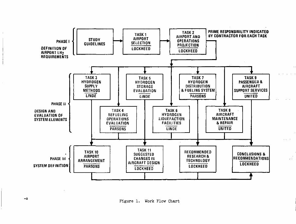
The technical approach used to accomplish the desired objectives is illustrated in Figure 1. The figure graphically illustrates the flow of the work described in detail in the report.
The scope of the work involved in formulating practical concepts of facilities, equipment, and procedures for operating hydrogen-fueled trans- port aircraft in the commercial environment in the 1990 decade required a diversity and depth of technical competence not.available in any one company. Accordingly, Lockheed reached agreement with the following companies to participate in the study as team members on a subcontract basis in order to provide maximum competence and experience in critical areas. The experience of each company which was utilized in the subject study is indicated:
0 Ralph PI. Parsons Company, Pasadena, California - o Air Terminal and aircraft fueling facilities design and
construction
o Hydrogen distribution system Uesign and construction
o Overall airport system conceptual arrangement.
0 Linde Division of Union Carbide Corporation, Tonawanda, New York -
o Hydrogen manufacture, liquefaction, and storage
o LH2 supply methods.
0 United Airlines, San Francisco, California -
o Airline ground services and air terminal operations
o Aircraft maintenance and repair procedures.
These capabilities, combined with Lockheed-California Company's know- le.dge of the design characteristics and support requirements of the subject hydyogen fueled aircraft provided the required basis for evaluation of the critical elements of this program and permitted formulation of viable concepts for air terminal facilities and operations.
As shown on the flow chart (Figure 1) , the program was performed in three phases: Phase I, definition of airport LH2 requirements; Phase 11, design and evaluation of system elements; and Phase 111, selection of a preferred arrangement of elements, and the complete air terminal complex for the selected airport formulated, described, and evaluated. This pro- cedure of evaluating alternate arrangements of system elements and selecting preferred concepts for formulation of an air terminal complex provided the information necessary to meet the objectives of this study.
6
I
PHASE I
OEFlNlTlON OF AIRPORT LH2 REQUIREMENTS
STUDY GUIDELINES
Z!iT~ H LOCKHEED I , TASK 2 PRIME RESPONSIBILITY INDICATED AIRPORT AND BY CONTRACTOR FOR EACH TASK OPERATIONS PROJECTION SELECTION
LOCKHEEO
PHASE II
DESIGN AND EVALUATION OF SYSTEM ELEMENTS I
HYDROGEN SUPPLY
METHODS
PHASE Ill
SYSTEM DEFINITION
I
TASK 5 TASK 7 HYDROGEN HYDROGEN STORAGE DISTRIBUTION
EVALUATION & FUELING SYSTEM
r I
TASK 9 PASSENGER &
AIRCRAFT SUPPORT SERVICES
UNITE0
REFUELING HYDROGEN AIRCRAFT OPERATIONS LIQUEFACTION MAINTENANCE EVALUATION FACILITIES &REPAIR
PARSONS LlNDE UNITED
I I I * 1 v v I r 1 t 1 I
I.
1
1 AIRPORT 1 1 S$Y:LD 1 1 REcoM,"" 1 1 CONCLrONS & 1
RECOMMENDATIONS
PARSONS LOCKHEEO
CHANGES IN RESEARCH & ARRANGEMENT TECHNOLOGY AIRCRAFT DESIGN
LOCKHEED LOCKHEEO
Figure 1. Work Flow Chart

The aircraft specified for the study were selected from Reference 2. They are shown in the artists concept drawing of Figure 2. These aircraft are both designed to carry 400 passengers 10 192 km (5500 n.mi.) at Mach 0.85. The essential difference in the aircraft is in the location of the fuel, one having external wing mounted tanks and the other internal (f'uselage) tanks located forward and aft of the passenger compartment. A general arrangement of the internal tank aircraft is shown in Figure 3 to illustrate the location of the fuel tanks and the double deck passenger compartment typical of both aircraft. From both economic and performance considerations the internal tank is the preferred configuration, however the operational and servicing aspects of both aircraft were further evaluated in this study.
3. PHASE 1 - DEFINITION OF AIRPORT LH2 REQUIREMENTS
The initial phase of the work established the basis on which assessment of the impact the use of LH2 as a fuel in long-range transport aircraft would have on airport facilities and operations should be made. The first step was to select an airport which would be satisfactory for the 'purposes; the second was to define a traffic level and associated fuel requirements, which would serve as a model for designing the airport LH2 fuel supply, and distribution system. These two steps were performed in Tasks 1 and 2, respectively.
3.1 Task 1: Airport Selection
The first task was to select an airport to serve as a basis for study and evaluation of the services, materials, equipment, and land usage which would be required at a representative air terminal to implement the use of liquid hydrogen (LH2) in future commercial transport aircraft.
General criteria for establishing a viable list of candidate airports were the following:
a. Must be a major airport with a representative mix of both long range and short range traffic forecast for the 1990 decade.
b. The 1990 plan for the airport should allow consideration of any of several methods of performing LH2 fueling operations in order to avoid artificial constraint of the study.
c. All basic data about the airport's 1990 projections should be readily available to the contractor.
d. The selected airport should be a representative example of the problems which will be encountered. The objectives of the study were best served by selecting neither the easiest nor the most difficult airport to convert to LH2.
8

Figure 2. Typical LH2-Fueled Subsonic-Transport. Aircraft
9

0 San Francisco (SFO)
0 Chicago O'Hare (ORD)
Final selection of the airport to be used as a basis for evaluation in the subject study resulted from the considerations summarized in Table 11. It should be noted that all three of these airports were considered to be acceptable insofar as the purposes of the study are concerned. The evalua- tions of Table I1 are purely relative. The ratings were made in order to select one airport on which the study efforts could be focused. Accordingly, San Francisco (SFO) airport, shown in Figure 4 in a recent aerial photograph, was recommended by Lockheed as the airport to be used for the subject evalua- tions. The recommendation was approved by NASA.
3.2 Task 2: Traffic and Fuel Requirements
The objective of Task 2 was to determine the following information based on the utilization projected for the subject LH2 fueled, wide-boaied aircraft at the specified airport in the designated time period.
0 Flights per day
0 Fuel requirements
o Flow rate vs time of day for peak usage
o Total quantity per day for peak month.
These data were then used in the remainder of the study as a basis for consideration in sizing the required airport facilities and planning the ground operations for the projected fleet of LH2-fueledY wide-bodied aircraft.
3.2.1 Implementation timetable. - Consideration of the following sequence of events ser-fining the timing for initiation of use of LH2 in long range, commercial transport aircraft. Note that the timing of the events is presented as feasible, not as a prediction of what might actually happen. The actual events which occur are dependent on major uncertainties such as:
0 An authoritative decision being made to have the commercial air transport industry become an early, major user of hydrogen as file1 for new, advanced design aircraft.
10

/#',, - . ." -
(OP8)28'72 """I "-I
~ ..
I . . , I ?
. . _.
1


Ti *,E I. PRELIMINARY AIRPORi SCREENING
Candidate Airport
S a n Francisco (SF0 1 Honolulu (HNL)
Dulles ( IAD)
Miami (MIA)
New York (JFK)
miles / Ft. Worth (Dm) Atlanta ( ATL )
Chicago (ORD)
Passenger Handling
2onf igurat ion4
satellites/ Linear
Transporters
Pier
flix (most are pier or satellite)
Linear
Pier
Linear/Pier
Type of Traffic Forecast for 1990-95
May be primarily short haul
Long and short haul, through and turnaround
Primarily long haul
Long and short haul, through and turnaround
Lower fraction is long haul
Large fraction is long haul
Long and short haul, through and tunaround
Large fraction is short to medium
Long and short haul, through and turnaround
Antic,pated Dif f icult3 of Providing LH2
Facilities
Representative
Representative (fill may be required:
Representative ( fill required)
Easiest
Representative
Difficult
Easy
Representative
Representative
Comments
Long haul future un- certain. New airport being planned.
Selected
GH2 supply problem and traffic mix not representative
Not representative, too easy I
Selected 1 I
Not representative, too difficult because of space problem
Not representative, too easy
Low fraction of long haul
Selected
"Present arrangement. Future plans at each airport generally call for expansion along present lines; "
however, most could develop nearly any configuration required.

I
TABLE 11. FINAL AIRPORT SELECTION,
- Consideration
Space available for expansion
Traffic mix forecast for 1990-95
Availability of airport data to contractor
Selection (in order of preference)
1 San Francisco
(SF0
OK
OK
Best
1
rport Mi ami (MIA 1
OK
Poorest
Poorest
3
Poorest
Best
OK
2
~ NOTE: All three airports are acceptable for purposes of the study. Ratings were assigned to select one airport for analysis.
I
0 The timing and priority assigned to this decision.
0 The efficacy with which a plan is implemented to mine the coal and to create plants to manufacture hydrogen in suf-ficient quantities, and for designated airports to be equipped with necessary liquefac- tion, storage, and handling facilities.
0 Coordination of U.S. emphasis on aircraft usage of LH2 with govern- ments of other countries which are major participants in inter- national air travel.
However, considering the serious nature of the problems associated with assuring an adequate worldwide supply of petroleum fuel for commercial trans- port aircraft at an economically acceptable price, and the many attractive advantages which can be realized from switching advanced designs of such air- craft to LH2, it is felt that the possibility of necessary positive action being taken is high and that the suggested timetable for implementing this change is feasible.
It should be recognized, and is hereby emphasized, that development of a rigorous analysis of all the interrelationships involved in this general subject of changing fuel systems for the air transport industry is a subject deserving of very serious attention. A comprehensive societal impact study should be made to explore properly the ramifications such a change would make in established economic, industrial, commercial, regulatory, and social processes.

Figure 4. Aerial Photo of S a n Francisco International Airport

Figure 5 p re sen t s a feasible timetable for elements of the series of actions which must occur i n o r d e r that s i g n i f i c a n t numbers of long-range, mg-f'ueled t r anspor t a i r c ra f t can ope ra t e from S a n Francisco Internat ional f i r p o r t (SFO) by t h e year 2000. The development a c t i v i t y shown i n t h e figure i s d iv ided in to f ive major categories. Each of these elements must be addressed md successful ly accomplished in order for t he end ob jec t ive t o be achieved.
Item No. 1: Hydrogen Technology Development
This item i s a program of development of hydrogen technology f o r a i r c r a f t appl icat ion. It i s descr ibed in Sect ion 6 of NASA CR-132559 (Ref. 2 ) . A s indicated i n Figure 5, a program of technology development has already been i n i t i a t e d by NASA and should be act ively pursued in order to provide the spec ia l knowledge of hydrogen-peculiar equipment and systems needed t o com- plete design and development of t h e first p roduc t ion a i r c ra f t , Item 2 , i n t imely fashion.
Item No. 2: Aircraf t Development
The scheduling of Item No. 2 i s c o n s i s t e n t w i t h c u r r e n t p r a c t i c e i n t h e indus t ry fo r development of l a r g e a i r c r a f t i n c o r p o r a t i n g advanced design features. After completion of development of c r i t i c a l hydrogen technology and a f t e r a series o f d e s i g n s t u d i e s t o s e l e c t a prefer red bas ic concept , two years i s p e r m i t t e d t o e s t a b l i s h de t a i l des ign of the p roduct ion a i rc raf t . After des ign f reeze , and whi le f ina l des ign de ta i l s are completed, fabrica- t ion of long lead time items i s begun. Fabr ica t ion of the , f i r s t a i rc raf t can be completed i n just ove r t h ree yea r s , s ix yea r s after se l ec t ion o f a pre- fe r red des ign concept . F i r s t f l igh t o f th i s a i rc raf t could occur approxi - mately one y e a r l a t e r a f t e r a program of extensive ground testing.
Delivery of the first a i r c r a f t f o r o p e r a t i o n a l a i r l i n e se rv ice would normally follow about three years l a t e r , p u t t i n g i n i t i a l commercial operation o,f a hydrogen-fue led t ranspor t a i rc raf t in 1995. Normal build-up of pro- duc t ion de l iver ies would r e s u l t i n 22 a i r c ra f t be ing pu t i n s e rv i ce t he first year , 48 the second year, and 220 within f ive years .
The buildup of production of LHyfueled aircraft can be much f a s t e r t han de l ive r i e s can be a s s imi l a t ed i n commercial operations. Development of gas- eous hydrogen production capability, Item 4, a n d a i r p o r t f a c i l i t i e s , Item 5 , w i l l pace the growth of LH2-transport aircraft usage. Nevertheless, aircraft development must be started i n about 1985 i n o r d e r t h a t a i r c r a f t can be d e l i v e r e d f o r i n i t i a l o p e r a t i o n i n 1995.
Item No. 3: Engine Development
Engine development would proceed i n p a r a l l e l w i t h t h e a i r c r a f t develop- ment so de l ivery o f the f i r s t set o f eng ines fo r i n s t a l l a t ion on the prototype aircraft could occur approximately one year before first f l i g h t .
16

I
CALENDAR YEARS 1975 1980 1985 1990 1995 2Ooo
ITEM 6 7 8 9 1 2 3 4 6 7 8 9 1 2 3 4 6 7 8 9 I 1. HYDROGEN TECHNOLOGY
DEVELOPMENT
3. ENGINE DEVELOPMENT
I L
L AIRCRAFT F,,,,,,,,,,,,, ,
, ,, ,,.,, .
5. HYDROGEN AIRPORT FACILITIES DEVELOPMENT I
I DEVELOP
- 1 I I I
I I FIRST I I DESIGN 4 FINAL
I PRODUCTION I
Figure 5 . Schedule f o r Operational Development of LH Transport Aircraft 2

Item No. 4 : Hydrogen Production and Distribution ~~ System Development'. - .
. .
Development of a c a p a b i l i t y f o r production and distribution of- adequate q u a n t i t i e s of gaseous hydrogen ( G H 2 ) , w i l l r equi re immedia te p r ior i ty a t ten- t i o n . This i s t h e c r i t i c a l p a c i n g item of the en t i re under tak ing .
The quan t i t i e s o f GH2 required to support a i r l ine usage of long-range, wide-bodied a i r c r a f t i n t h e time p e r i o d s t a r t i n g i n t h e 1990 decade-will r equ i r e dependence on the production processes which are current ly understood and basical ly developed, as ide from steam reforming of natural gas o r p a r t i a l ox ida t ion of c rude o i l , fo r which nei ther resource can logical ly be considered t o be ava i lab le for the p resent purpose . These production processes are gasi- f icat ion of coal and/or organic wastes, and e lectrolysis of water , us ing n u c l e a r f i s s i o n r e a c t o r s t o g e n e r a t e t h e e l e c t r i c i t y .
Both processes would require long lead times f o r development of a capa- b i l i ty for supply ing adequate quant i t ies of GH2. The time requ i r ed t o expand our coa l min ing capabi l i ty s ign i f icant ly i s estimated at about 1 0 years . The lead t ime for bu i ld ing new nuclear reac tors i s currently about twe'lve years.
Clearly, it w i l l take a h igh order o f na t iona l incent ive , similar t o t h a t demonstrated i n t h e Manhattan Project and in the U.S. Apollo "Man on t h e Moon i n t h i s Decade'' program, t o accomplish the tasks r e q u i r e d t o have adequate GH2 product ion and tyansmiss ion capabi l i ty ava i lab le in t ime to supply the needs of commercial t r a n s p o r t a i r c r a f t s t a r t i n g e a r l y i n t h e 1990 decade, assuming go-ahead f o r a program to conver t U.S. commercial a i r c r a f t t o LH2 f u e l i s given in 1980 (see Figure 5 ) .
I n i t i a l u s e of LH2-fueled aircraf t can occur when at least two a i r p o r t s which c o n s t i t u t e a c i ty-pa i r involv ing s ign i f icant rec iproca l t ra f f ic are equipped w i t h LH2 re fue l ing and maintenance capabi l i ty . Real is t ical ly , it i s considered tha t 1995 would be a c red ib l e date t o i n d i c a t e i n i t i a l capa- b i l i ty for supply ing gaseous hydrogen in subs tan t ia l quant i t ies for l ique- fact ion a t two a i rpor t s . This da te i s r e f l e c t e d i n t h e t i m e t a b l e shown i n Figure 5 .
Item No. 5 : Hydrogen Ai rpor t Fac i l i t i e s Development
The objective of t h i s study was t o provide an assessment. of the problems and requirements of handling LH2-fueled t ranspor t a i rc raf t , a t a designated a i r p o r t . It would serve no useful purpose i f the s tudy was conducted f o r an early t ime period during which only a f e w LH2-fueled a i rc raf t could be serv iced because ava i lab i l i ty of hydrogen l i m i t e d t h e number o f a i r p o r t s t o and from which t h e LH2 a i r c r a f t c o u l d f l y . The purpose of Task 2 was t o make an evaluat ion of the supply potent ia l and the demand requirements for LH2 i n o r d e r t o s e l e c t a time period which offered a c red ib le bas i s for s tudying the operational problems of LH2-fueled a i r c r a f t .
18

A comprehensive study of t h i s s u b j e c t would include a de ta i led eva lua t ion of a potential schedule for prdviding an adequate supply of gaseous hydrogen !
t o a l l t h e a i r p o r t s i n v o l v e d i n i n i t i a t i n g use of LH2 as f u e l f o r commercial t r a n s p o r t a i r c r a f t . The present study i s l i m i t e d t o c o n s i d e r a t i o n o f the a i r p o r t f a c i l i t i e s r e q u i r e d a t SF0 fo r l i que fac t ion , s to rage , and t r ans fe r o f t h e hydrogen. Judgments concerning i n i t i a l a v a i l a b i l i t y of GH2 f o r d e l i v e r y t o a i r p o r t s i tes across the country must t h e r e f o r e b e l i m i t e d t o t h e con- s iderat ions expressed under I t e m 4, above. It may be added, however, t h a t although 15 years i s probably a reasonable estimate f o r i n i t i a l GH2 de l ive ry capabi l i ty , succeeding a i rpor t s could be expec ted to be p rovided wi th the required gaseous hydrogen at an increasing rate, paced primarily by funding l i m i t a t i o n s and start dates. It would be expec ted t ha t t he capab i l i t y f o r mining coa l wculd be developed, and/or that nuclear plant design would be standardized and that subs t an t i a l s av ings i n bo th cos t and construction time could be effected a f t e r t h e i n i t i a l e f f o r t s .
Design and construct ion of hydrogen l iquefact ion plants i s much more mundane than developing major new coa l mines and bui lding coal gasif icat ion p l a n t s , or equivalent ly , bui lding nuclear reactors . For example, it i s estimated t h a t it w i l l require about .42 months for design and construction of t h e f i r s t 226 800 kg/day (250 ton/day) hydrogen l iquefact ion plant . Succeeding plants can be expected t o be b u i l t i n 36 months. Accordingly, it i s f e l t t h a t development of hydrogen liquefaction, storage, and handling f a c i l i t i e s a t a i rports around t h e country, w i t h proper lead time and planning, can proceed on a schedule which matches the projected avai labi l i ty of the GH2.
3.2.2 Project ion of LH2 requirement at SFO. - With t h i s project ion of a feasible schedu le fo r ava i l ab i l i t y o f f ac i l i t i e s t o manufac tu re and use LH2, t h e problem then w a s t o determine the quantity of LH2 fue l r equ i r ed a t San Franc isco a i rpor t as a funct ion of t i m e , s t a r t i n g i n 1995, and as a funct ion of the a i r p o r t s which could be added t o t h e l i s t as they might be equipped p rope r ly t o s e rv i ce t h e subject long-range, LH2-fueled t r a n s p o r t a i r c r a f t . A s more c i t y p a i r s a r e added t o t h e l i s t , more LH2-fueled a i r c r a f t must be handled a t SF0 and the assessment of t h e f a c i l i t y , equipment, and handling problems becomes more meaningful.
The ATA Airport Demand Forecast (Ref. 5 ) , w a s used t o e s t a b l i s h an es t i - mate o f t he cu r ren t and fu tu re t r a f f i c i nvo lv ing l ong r ange , l a rge a i r c ra f t opera t ing in to and out of SFO. Figure 6 i s a plot of passenger enplanements fo recas t as a funct ion of years for t he San Francisco Hub, which includes SFO, t h e Oakland a i r p o r t ( O A K ) , and San Jose a i rpo r t (SJC). I n t e r s t a t e , i n t e r n a t i o n a l , a n d i n t r a s t a t e f l i g h t s a r e a l l shown t o i n d i c a t e t h e t o t a l a c t i v i t y of a l l t h e s c h e d u l e d c a r r i e r s i n t h a t hub region. According t o t h e reference, and as shown i n the f i g u r e , t h e number of enplanements projected for SF0 in years subsequent to 1990 i s not expected t o i n c r e a s e s u b s t a n t i a l l y because of s a tu ra t ion o f SF0 runway capab i l i t y .
Assumptions and guidel ines for the s tudy to determine the t raff ic and fuel f low requirements for the San Francisco a i rport in the 1995 - 2000 time period are l i s t e d i n Table 111. A l i s t of ten domest ic a i rports , including
19

I I I I lllIIlIlll11l111l111111~ 11l11111l1111lIIlIIIIlIIlIIIIlIIlI
28
26
24 I
v) a
a ; 22
4 u 20
.J 3 W n I 18 - 2
16 to 0 ' 14 a > \ v) 5 12
Y . 2 10
w 8 a
W
.J n z
0
$ 6
n
W
2 4
2
0
""_
1970 1980 1990
YEAR
2006
Figure 6 . San Francisco Hub Airport Traff ic Forecast
20

TABLF: 111. ASSUMPTIONS AND GUIDELINES - LH2 AIRCRAFT TRAFFIC FORECAST
1. Basis o f t r a f f i c f o r e c a s t i s "ATA Airport Demand Forecast - San Francisco Hub Report" by A i r Transport Association of America, Draft Copy dated June 1975 ( R e f . 5 ) . No intrastate t r a f f i c w i l l be considered.
2. By 2000 A.D. the following major terminals w i l l have LH2 l ique fac t ion and LH2 a i r c r a f t h a n d l i n g f a c i l i t i e s :
a. Domestic
1. SF0 - San Francisco 6. ATL - A t l a n t a 2. ORD - Chicago 7. LAD - Dulles 3. HNL - Honolulu 8. MIA - M i a m i 4. JFK - New York 9. M C I - Kansas City 5. DFW - Dallas, Ft. Worth 10. LOS - Los Angeles
b. Foreign
TYO - Tokyo CDG - P a r i s LHR - London (Heathrow) FCO - Rome
3. F l igh t s from SF0 t o t h e c i t i e s i n 2 , above, w i l l be assumed t o have t h e same d i s t r i b u t i o n as shown i n t h e August 1973 O f f i c i a l A i r l i n e Guide ( R e f . 6 ) .
4 . LH2 a i r c r a f t w i l l be used only on d i r e c t , non-stop f l i g h t s from SF0 t o the c i t r e s i n 2 , above , excep t t hey w i l l a lso be used on through- f l i g h t s v i a LOS t o t h e c i t i e s i n 2a.
5. The only a i rp lane(s ) used w i l l be the LH2-400 pax, 10 192 km (5500 n .mi . ) range versions- defined in NASA CR-132559 (Ref. 2 ) .
6 . No d i rec t non-s top f l igh ts from SF0 t o Europe are made at present ; however, by 2000 A.D. it i s a n t i c i p a t e d t h a t t h e demand w i l l . support a reasonable number of such f l ights . This demand wi l l . be e s t ima ted .
21

SFO, which were s e l e c t e d as be ing log ica l candida tes for ear ly ins - ta l la t ion of hydrogen f u e l and r e l a t e d f a c i l i t i e s i s shown as item 2 i n t h e t a b l e . Loca t ion of these c i t ies on t h e map of Figure 7 shows tha t they provide good geographical coverage of the more populated areas of the United States .
The f o u r f o r e i g n a i r p o r t s l i s t e d were a l s o ass.umed t o have LH2 fue l ing c a p a b i l i t y t o p r o v i d e f o r p r o j e c t e d i n t e r n a t i o n a l f l i g h t s from SFO. A s noted, t h e A i r l i n e Guide (Ref. 6 ) provided data on t r a f f i c i n mid-August, 1973, between SF0 and each o f t he domes t i c a i rpo r t s l i s t ed , i nc lud ing f l i gh t s t o Tokyo. T r a f f i c t o t h e o t h e r f o r e i g n a i r p o r t s l i s t e d w a s assumed as described subsequently.
The following procedure was used t o a r r i v e a t projections of passenger and LH2 f u e l e d a i r c r a f t t r a f f i c , p l u s estimates of fuel f low requirements, at SF0 f o r t h e 1995 - 2000 t ime period.
LH2 Demand Estimation Procedure (1995' - 2000) I n t e r s t a t e :
a. Using t h e O f f i c i a l A i r l i n e Guide f o r t h e peak month (August) in 1973 the number of nonstop f l ights , departure t imes, and equipment, used we're ob ta ined for the candida te c i ty -pa i rs .
b. The sea t ing capac i ty o f each a i rc raf t , mul t ip l ied by the 1973 in t e r - s t a t e pay load f ac to r (0 .54 ) from Ref. 5 , times :he f l ight f requency (above) gave the number of passenger enplanemen1;s i n August 1973.
c . The r a t i o of number of August f l i g h t s t o t h e monthly average was found from Ref. 5 . With t h i s r a t i o , t h e t o t a l number of enplane-- ments per year to each c i ty-pa i r w a s calculatEd. Yo- 1973.
d. From Ref. 5 , t h e growth of i n t e r s t a t e t r a f f i c fro 1973 t o 2000 w a s found t o be a fac tor o f 1.974 ( 5 . 6 7 t o 11.19 x 10% enplanements ) . Using t h i s growth f a c t o r , t h e 2000 A.D. enplanements was found f o r each c i ty , assuming the d i s t r ibu t ion by c i t y remained the same as 1973.
e . Using t h e 2000 A.D. ave rage pay load f ac to r fo r i n t e r s t a t e t r a f f i c (0.64) from Ref. 5 , t he number o f f l i g h t s t o each c i t y w a s ca l cu la t ed .
f . Block f u e l w a s determined based on the equivalent s t i l l -a i r f l i g h t d i s t ances t o each c i ty . Block fuel t imes the f l ight f requency, plus boi l -off and miscel laneous losses , gave the total year ly fuel con- sumption t o each c i ty .
22

W Iu Figure 7. Ten Airports Projected for I n i t i a l LH F a c i l i t i e s
2

LH2 Demand Estimation Procedure (1995 - 2000) International:
The international consumption was calculated in a sinilar manner with the following exceptions:
a. The only direct international flights from SF0 in 1973 were to Tokyo (TYO). Since it was felt that by 2000 A.D. direct flights to Europe will be justified, they were arbitrarily added to the 1973 schedule as follows:
City Flts/Wk
TY 0 14 - Actual
CDG
FCO 4 71 Assumed b. The 1973 payload factor for international flights was 0.35 from
Ref. 6.
c. The 2000 A.D. payload factor is estimated to be 0.65.
d. The growth of enplanements for international traffic from 1973 to 2000 is a factor of 4.014 (0.292 to 1.172 x 10⁶) , from Ref. 5.
Results of the calculations are shown in Tables IVY V, and VI. It should be noted that the quantities of fuel shown are those required for loading in the aircraft and. do not reflect losses in production, storage, or transfer. Actual plant output will consider these losses as well as excess capacity required for outage of production units.
A s a result of the foregoing assessment, the schedule shown in Figure 8 was formulated to represent a feasible sequence. and timing for installation of liquid hydrogen facilities at the subject airports. The schedule for construction of facilities at the U.S. domestic airports is of interest, not only because it enters into the planning for fuel and aircraft handling facilities at SF0 itself, but also because it affects the schedule f o r con- struction of total gaseous hydrogen macufacturing capability in the U.S. The schedule for instituting LH2 use at foreign airports is useful in this study only as it affects planning at SFO.
A period of 30 months is provided for conceptual design and analysis of candidate arrangements of airport facilities. Final detail design of a pre- ferred arrangement would be completed in 6 to 8 months and construction could be expected to take 36 months.
24

TABLE I V . PROJECTION OF TOTAL ENPLANEMENTS TO 2000 A.D. (LH, A i r c r a f t From SFO)
I n t e r s t a t e
Connection t o
ORD
HNL
JFK DFW ATL
I A D
MIA
M C I
LAX
Total LH2
r 1973
1.331
v L
T o t a l I n t e r s t a t e ( J e t A + LH2)
% LH2 Travel
EnP Y r
( 3 ) ~
545 000
383 000
371 000
348 000
99 800
97 000
75 000
71 800
223 000
2 213 600 5 670 ooo
In t e rna t iona l :
TYO
4 020 CDG
37 020 4 020 LHR
74 050 1.34 8 040
21 180 2 300 FCO
37 020
%tal LH2 169 270 Tota l In te rna t iona l ( J e t A + LH2)
% LH2 Travel
Enp = Enplanements: Passenger Boardings
I
3rowth (4 1 Ratio
1 .! 73 5
2000
- = Yr Enp (3) (4
1 075 580
755 870 732 180 686 790 196 960 191 430 148 000
1 4 1 700
440 100
4 368 610 11 190 000
39 .Ob%
4.014 148 600 297 240
148 600
85 020 I . . . . 679 460
1 172 000
58.0%
(1) Calculated from Ref 6 using seat ing capaci ty , f l ight f requency and 1973
( 2 ) Calculated from Ref 5 . l oad f ac to r from Ref 5.

TABLE V. PROJECTED TOTAL FUEL LOADED - LH2 AIRCRAFT AT SF0
(400 Pax - 1 0 192 km (5500 n.mi.) A i r c r a f t )
I n t e r s t a t e 2000 A . D . PLF = 0.64 (Ref. 4 ) PAX/FLT = 256
City
ORD
HNL
JFK
DFW
ATL
IAD
MIA
MCI
Rts/Yr (1)
4 201
2953 2860 2682
7 69
578 554
748
29.346 30.808 25.946
15.937 6.001 6.447
5.453 3.242
3.667
Subto ta l 126.85 (279.640) + 5% Losses 6.34 ( 13.98) Tot a1 133.19 (293.62)
J
I n t e r n a t i o n a l 2000 A . D . PLF = 0.65 (Ref. 4 ) PAX/FLT = 260
TYO 25.4 (56.007) 22 226 (49 000) 9497 (5125) 1143 LHR 11.03 (24.310) 19 278 ( 4 2 500) 8220 (4436) 572 CDG
7.35 (16.203) 22 549 (49 7 0 0 ) 9615 (5189) 326 FC 0
11.49 (25.340) 20 095 ( 4 4 300) 8576 (4628) 5 72
Sub to ta l 55.28 (121.860) + 5% Losses 2.76 ( 6.090) Tot a1 58.0 (127.950)
ESAD = Equivalent s t i l l a i r d i s t a n c e
PLF = Passenger load f ac to r
26

TABLE V I . SUMMARY OF LH2 LOADED AT SF0 - 2000 A.D.
h ters ta te
lnternational
rota1
58 038 ( 63 975)
3atio( 2 ) ?eak/Av@
1.331
1.57
"11 Mo/Avg (3) l o 3 kg/mo (tons/mo)
Peak Month
(tons/day ) kg /day

AIRPORT CITY
DOMESTIC
SF0
ORD
HNL
JFK
DFW
IAD
ATL
MI A
LAX
MCI
FOREIGN
TYO
CDG
LHR
FCO
SAN FRANCISCO
CHICAGO
HONOLULU
NEW YORK
DALLAS, FT. WORTH
WASHINGTON
ATLANTA
MIAMI
LOS AIUGELES
KANSAS CITY
TOKYO
PARIS
LONDON
ROME
, 1 2 3 4 5 6 7 8 9 I I I I I I I I
CONCE'PTUAL DES. AND P ILYSIS \
I..,
INAL DESIGI
,1 2 3 4 5 6 7 8 9 u RUCTION
I . . .. . . . - - -
LH2 LOADED AT S F 0 FOR FLIGHTS TO DESIGNATED
AIRPORTS
1' kg/YEAR
30.8 1
32.35
27.24
16.73
6.77
6.30
5.72
3.85
3.40
26.68
1207
11.58
7.72
(lo6 IbIYEAR)
(67.93)
(71.31)
(60.06)
(36.89)
14.92
(1 3.89)
(1 2.62)
( 8.49)
( 7.50)
(58.81 )
(26.61 )
(25.53)
(17.01)
Figure 8. Schedule for Construction of Airport Hydrogen F a c i l i t i e s
The construction schedule of the airport facilities is arranged approxi- mately in order of the fuel required per year at SF0 to service flights to the designated cities. The exception is Honolulu which requires slightly more fuel per year for flights from SFO, than do flights from SF0 to Chicago. The Chicago airport was scheduled for earlier oonstruction because the problem of supplying GH2 to Chicago was consi,dered to be simpler.
San Francisco and Chicago are provided with LH2 facilities as the initial, city-pair, with operational capability to begin in 1995 , the year. gase,ous hydrogen is scheduled to become available, see Figure 5. After a two year delay which provides for development and operational troubleshooting of the new facilities, additional airports come onstream at the rate of two per year domestically, plus one foreign airport. By 2000 A.D. all 10 domestic and 4 foreign airports are equipped with LH2 facilities.
For convenient reference, the quantity of LH2 loaded at SF0 per year for flights to each of the specified cities is listed. Losses which will ?e incurred during loading are not included; however, the 5 percent loss assumed to occur during use in the aircraft is included. These data come from Table V. On the same basis, the total quantities of LH2 loaded at SF0 each year are shown on Figure 9.
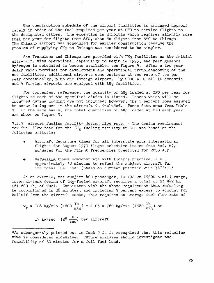
3.2.3 Airport fueling facility design flow rate. - The design requirement f o r fuel flow rate for the LHp fueling facility at SF0 was based on the following criteria:
-
e Aircraft departure times for all interstate plus international flights for August 1973 flight schedules (taken from Ref. 6), adjusted for the flight frequencies predicted f o r 2000 A.D.
Refueling times commensurate with today's practice, i.e., approximately 38 minutes to refuel the subject aircraft for its total fuel load (based on current practice with 747's).*
As an example, the subject 400 passenger, 10 192 km (5500 n.mi. ) range , internal-tank design of LH2-fueled aircraft requires a total of 27 942 kg (61 600 lb) of fuel. Consistent with the above requirement that refueling be accomplished in 38 minutes, and including 5 percent excess to account for boiloff from the aircraft tanks, this requires an average fuel flow rate of
w = 726 kg/min (1600 x) Ib X -1.05 = 762 kg/min (1680 z) or lb f
13 kg/sec (28 -) per aircraft lb sec
"As subsequently pointed out in Task 9 it is recognized that this refueling time is considered excessive. Future analyses should investigate $he feasibility of 30 minutes for a full fuel load.

kg/yr (Ib/yr) x106
191.2 (421.6)
400
300
QUANTITY LH2 LOADED PER YEAR AT SF0
200
(lo6 Ib/yr)
100
0
30.
k
176.3 (388.6) . - 152.6 (336.5)
L
117.1 (258.1)i b
a ,8 (67.9) r-
I 1 I I 1 1 1 1 I I I I I I 990 1 2 3 4 1995 6 7 8 9 2000
Figure 9 . T o t a l Quantity of LH2 Loaded per Year at SF0
30

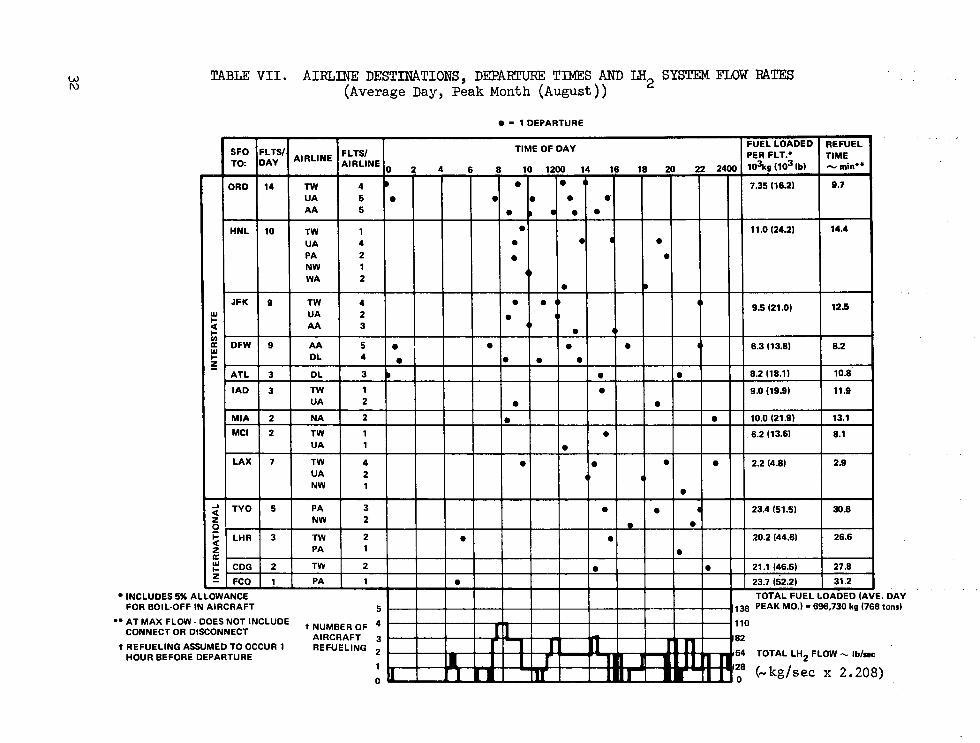
3.2.4 Data summary. - Table VIL presents a summary of data relative to enplanements of the LH2-fueled aircraft at SF0 with the airlines and destin- ations noted. It also shows corresponding flow rates of LH2 which are required for the ground facility to accommodate the flight schedules. The data are presented as a function of time of day for an average day in the peak month (August) in 2000 A . D . With the information presented, the number of gate positions and refueling stations required at SF0 can be determined and the ground operations analyzed. These items, plus the statement in Table VI1 of the total amount of LH2 required on an average day in the peak month, viz., 697 730 kg/day (768 tons/day) , constitute the information required from Task 2.
4. PHASE I1 - DESIGN AND EVALUATION OF SYSTEM ELEMENTS
Overall requirements for the quantity and flow/rate of LH2 which will be needed at SF0 in 2000 A.D. were established in Phase I. In Phase 11, the characteristics and requirements of facilities, equipment, and services which will be needed to operate the subject LH2-fueled long range 'transport aircraft are examined.
4.1 Task 3: Hydrogen Supply Methods
The object of this task was to select a suitable and economic method for the supply of liquid hydrogen to the airport site in sufficient quantity to meet scheduled aircraft fueling requirements. The principal decision made was that of locating the site for the hydrogen liquefaction facility. The required area for a plant of the capacity contemplated is quite large and for reasons of property availability and/or cost, the plant might have to be located at some distance from the airport.
For the study, three different methods of transporting liquid hydrogen between the hydrogen liquefier and liquid hydrogen receiving-storage tanks located at the airport were considered:
a. Vacuum jacketed pipeline (VJ)
b. Truck-trailer using existing commercial vehicles of 5O.Om 3 (13 200 gal) capacity.
c. Railroad tank car using existing commercial railcars of 107.lm 3
(28 300 gal) capacity.
A source of crude (96.6% purity) gaseous hydrogen was assumed to be avai1,able at a distance of 161 km (100 miles) from the airport. The economics of hydrogen transport as a function of distance of the liquefac- tion facility from the airport was determined for distances of 161, 80 .2 , 16.1, 8 .02 , 1.61 and 0 (at the airport) km (100, 50, 10, 5 , 1 and 0 miles).
31
TABU V I I . A I R L I N E DESTINATIONS, DEPARTURE TIMES AND LH2 SYSTEM FLOW RATES (Average Day, Peak Month (August))
a - 1 DEPARTURE
INCLUDES 5% 1 FOR BOIL-OFF
r
4LL IN
** AT MAX FLOW. DOES NOT INCLUDE CONNECT OR DISCONNECT
t REFUELING ASSUMED TO OCCUR 1 HOUR BEFORE DEPARTURE
t NUMBER OF AIRCRAFT REFUELING
4 110
3 02 2 54
1 20
0 0
i . DAY I tons)
TOTAL LHZ FLOW - I b / w
(-kg/sec x 2.208)

4.1.1 Evaluation of distribution system losses. - Distribution system losses will amount to a considerable percentage of the aircraft block fuel require- ments so that, prior to evaluating the economics of liquid hydrogen supply systems, an estimate had to be made of the magnitude of these losses. This was done in considerable detail on an assumed fueling circuit arrangement and included fueling circuit losses, aircraft on-board losses, and connection losses between the aircraft and fueling system (see Appendix A ) . Although the assumed fueling circuit configuration does not agree precisely with the final Task 7 version, the similarity is sufficiently good to permit use in the economic comparisons of this task. The sum of the block fuel require- ments, the fueling system losses, and the transport losses constitutes the total quantity of LH2 which must be produced by the liquefier and transported to the airport.
Table VI11 summarizes the estimated losses for each of eight different combinations of transport and tank operations comprised of four transport methods and two tank operating methods.
Transport methods :
a. On-site liquefier - no transport
b. Truck-trailer transport
c. Railcar transport
d. Vacuum insulated pipeline transport
Tank cperating methods:
1. Uninterrupted fueling from full to empty tank, via pump, requiring only one tank pressurization.
2. Interrupted operation, via pump, fueling aircraft individually with tank pressurization required f o r each fueling operation.
Fueling losses are minimized, of course, with the on-site liquifier, when using the less severe method of tank operations (Method #l). In this situation, cumulative losses amount to 15.7 percent of net engine fuel requirements. Losses increase to 23.5 percent with intermittent type of tank operations (Method # 2 ) .
Cumulative losses due to operations plus transport are least for VJ pipeline transport of liquid over nearly the entire 161 km (100 mile) dis- tance. Pipeline losses are a strong function of distance while losses incurred in trailer or tankcar transport are nearly independent of distance. Shorthaul losses are much smaller for VJ transport while long-haul losses are comparable for distances of 80.2 to 161 km (50 to 100 mile 1. Losses as great as 51.9 percent are possible and apply to the combination of trailer haulage and intermittent fueling operations.
33
Losse's were also dete.rmined for pressure transfer type of tank opera- tions and although not summarized in Table V I I I , the detailed results may be found in Appendix A. Because of the need for frequent blow down and repres- surization operations and because of the relatively great pressure required for transfer, tank losses alone are extremely high and will amount to 52.7 percent. The combined overall loss for this system, including refueling and transport (tankcar) loss, amount to 185 percent of net engine requirements.
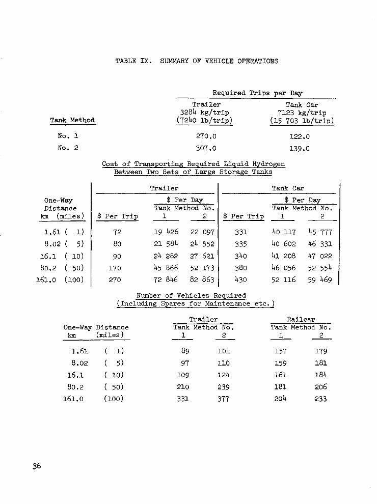
Table IX summarizes vehicle operations. For peak-month operation, at least 270 trailer trips or 121 tankcar trips and perhaps as many as 307 trailer trips or 139 tankcar trips would be required daily. Such a large volume of traffic at SF0 would virtually preclude vehicle delivery of LH2 to the airport site.
Vehicle operating costs are also presented in Table IX as a function of distance and tank operating method. The tank car costs are for a leased locomotive or unit train approach. Daily operating costs for trailer and tankcar crossover at a distance of about 80.47 km (50 miles) and at $50 000, with trailer favored for shorter distances and railcar for longer. Trailer transport costs are fairly sensitive to distance because of change in driving time while railcar costs are not very sensitive to distance because a large proportion of the cost results from switching, etc. required at filling and emptying locations. Costs shown include amortization of the capital cost of the vehicles ($180 000 for the trailer and $400 000 for the tankcar) but not of pumps, piping, etc. in the fueling circuit. Table IX also lists fleet requirements for both trailer and tankcar operations.
4.1.2 Hydrogen gas pipeline. - The cost for transporting 8.888 kg/s (846.5 tons/day)' of gaseous hydrogen from the hydrogen source to the liquefier f o r distances of 80.2 to 161 km (50 to 100 miles) via pipeline is shown in Table X and Figure 10. The cost includes investment in a 76.2 cm (30 in.) diameter pipe (optimally selected), as well as investment and operating cost for associated compressors. The total cost is defined as the present value of investment plus operating costs via discounted cash flow techniques. More specific information concerning the basis for the cost evaluation is pre- sented in section 4.1.7, Economic analysis for present value.
4.1'.3 Vacuum jacketed pipeline. - Pipeline transmission of liquid hydrogen requires high-performance insulation to minimize heat transfer to the liquid within the pipe. This study assumes commercially available piping consisting of concentric pipes containing multiradiation shielded insulation in the evacuated annulus. The liquid hydrogen is piped directly from the hydrogen liquefier to the receiving storage tank at the airport site. Available pres- sure energy in the product stream of the liquefier is used as motive force for transmitting the liquid hydrogen. Sufficient pressure is maintained on the liquid at all locations to prevent occurrence of two-phase flow within the lines. Liquid losses resulting from heat in leakage as well as from frictional sources are considered to be pipeline operating cost. For present
34

TABLE V I I I . LH BOILOFF LOSSES AND PRODUCTION KEQUTCREMEIVTS 2~~~ VARIOUS SUPPLY METHODS
[Net LH Required t o Engines = 7.68 kg/s (731.4 tons, 'day)] 2
LOSSES :
Trailer Transport
Refueling operations (1) Tank opera t ions Vehicle operations Tank opera t ions ( 2 )
Tank Car Transport
Refueling operations (1) Tank ope rat ions Vehicle operations Tank opera t ions ( 2 )
Vacuum Pipel ine Transport
Refueling operations (1 ) Tank opera t ions P ipe l ine opera t ions :
Distance km miles "
1.61 (1) 8-02 ( 5 )
16 .1 (10) 80.2 (50)
161.0 (100)
PRODUCTION REQUIREMENTS:
On-s i te l iquef ie r Trailer Tank car Vacuum jacke ted p ipe l ine :
Distance kr miles "
1.61 (1) 8-02 ( 5 )
16.1 ( l o ) 161.9 (100 )
80.2 (50)
Tank Method No. 1
Loss .Cumulative z I -
12.2 3.2
11.8 3.2
12.2 3.2 9 .O 3.2
12.2 3.2
0.3 1.4 2.8
10.4 17.5
8.89 10 -25
5, .99
12.2 1 5 "7 29.4 33.5
12.2 1 5 - 7 26.1 30.1
12.2 15.7
16.1 17.4 19 .o 27.8 36.1
Tank Method No. 2
Loss Cumulative z
12.2 10 .o 11.8 10 .o
12.2 10 .o
9 .o 10 .o
1 2 - 2 10 .o
0.3 1 .4 2.8
10.4 17.5
9.48
il .40 11.67
9 - 5 1 9.61 9.74
10.47 11.14
12.2 23.5 38.1 51.9
12.2 23.5 34.5 48.4
12.2 23.5
23.8 25.1 26 .g 36.3 45 .O
(903.0 (1111.0 (1085.6
(1) From s t o r a g e t a n k t o a i r c r a f t f u e l t a n k . (2) For f i l l i n g v e h i c l e s .
35
Tank Method
No. 1
No. 2
One-way Distance
km (mi les )
1.61 ( 1)
16.1 ( 10)
161.0 ( l o o )
8.02 ( 5 )
80.2 ( 50)
TABLE I X . SUMMARY OF VEHICLE OPERATIONS
Required Trips per Day
Trailer Tank Car 3284 k g / t r i p 7123 k g / t r i p
(7240 l b / t r i p ) (15 703 l b / t r i p )
~ ~ ~. - .. . . ..
270.0
307 .O
Cost of Transporting Required Liquid Hydrogen Between Two Sets of Large Storage Tanks
T r a i l e r
$ Per Day Tank Method No.
$ Per Trip 1 2
72 19 426 22 097
80 2 1 584 24 552
90 24 282 27 621
170 45 866 52 173 270 72 846 82 863
122.0
139.0
Tank C a r
$ Per Day Tank Method No.
$ Per Trip 1 2
3 3 1 40 117 45 777
335 40 602 46 331 3 40 41 208 47 022
380 46 056 52 554 430 52 116 59 469
Number of Vehicles Required (.Including Spares for Maintenance etc. )
Tra i l e r Ra i l ca r One-way Distance Tank Method No. Tank Method No. km (miles 1 2 1 - 2
1.61 ( 1) 89 101 157 179
16.1 ( 10) 109 124 161 184 8.02 ( 5 ) 97 110 159 181
210 239 1 8 1 206
331 377 20 4 233

TABLE X. TOTAL COST (PRESENT VALLE) OF GASEOUS HYDROGEN PIPELINE
Pipel ine dis tance - km 80.2 145.0 153.0 159.0 161.0 - miles (50) (90) (95) (99) (100)
Costs in Mil l ions of Dollars
Investment
P ipe l ine
Compressor
Tota l
Operating cost
Present value
Investment
Operating cost
Tota l
17 -3 30.65 32.35 33.72 34.06 1.65 2.78 2.92 3.02 3.05
18.68 33.43 35.27 36.74 37.11
0.805 1.358 1.424 1.476 1.488
17.09 32.08 33.84 35.26 35.61 3.37 5.69 5 -96 6.18 6.23
20.46 37.77 39.80 41.44 41.84
37

-r - COST = PRESENTVALUE ,
DIAM. = 76.2 cm (30 in.)
/
DISTANCE - miles
1 I I I I I I I
90 100 110 120 130 140 150 160 I I I I 1 1 CI I
DISTANCE - km
Figure 10. Total Cost of Gaseous Hydrogen P ipe l ine

purposes, the lost hydrogen is assumed t o be nonrecoverable. Table X I pre- s en t s a summary o f i n s t a l l ed cos t o f V J p ipe l ine fo r p ipe l ine d i s t ances o f from 1.61 t o 161 km (1 t o 100 miles) f o r t h e d e l i v e r y o f 8.888 kg/s (846.5 tons/day) of hydrogen l iquid i n t o t h e a i r p o r t s t o r a g e t a n k .
For purposes of developing the economics for the Task 3 study, a u n i t cos t of LH2, amounting t o $ 5 . 6 9 / ~ ($6/106 B t u ) based on gross heat ing value o r 80.824/kg (36.664/1b), was s e l e c t e d from a previous study (Ref. 7 ) . The actual cost of l iquid hydrogen a t SF0 was later determined i n t h e Task 6 study t o be about 1 2 percent greater (Sect ion 5.1.2.3).
4 .1 .4 Truck-trai ler mansport . - A summary of loss a n a l y s i s f o r trailer t r anspor t o f l i qu id hydrogen i s presented in Table V I I I . I n o rde r t o supp ly 7.680 kg/s (731.4 tons pe r day ) ne t fue l t o t he eng ines , 8.888 kg/s (846.5 tons per day) must be suppl ied in to the on-s i te s torage t anks (assuming tank method #1) and 10.253 kg/s (976.5 tons per day) must be l i q u e f i e d . The difference between 10.253 and 8.888 = 1.365 kg/s (976.5 and 846.5 = 130 tons per day) represents the vaporizat ion loss incurred as a r e s u l t o f . trailer operations. Trailer t ranspor t requi res an addi t iona l set of storage tanks a t t h e l i q u e f i e r s i t e which are used for receiving hydrogen from t h e l i q u e f i e r and for dispensing it t o t h e trailers. Investment for these tanks is included i n t h e c o s t of t r a i l e r o p e r a t i o n . The investment in a maintenance building for the t ruck f l e e t as w e l l as f i l l i n g s t a t i o n s a t t he l i que fac t ion and air- po r t s i tes i s also included. Table X I 1 presents a cos t summary f o r t ra i le r t ranspor t opera t ions .
TABLE X I . TOTAL COST (PRESENT VALUE) OF TRANSMITTING LIQUID HYDROGEN V I A VACUUM JACKETED PIPELINE
- -~ ~~
Pipel ine dis tance - km 1.61 8.02 16.1 80.2 161 - miles (1) ( 5 ) (10) ( 5 0 ) (100)
Pipe diameter - cm 20.3 20.3 20.3 25 .4 30.5 - inches ( 8 ) ( 8 ) ( 8 ) (10) ( 1 2 )
Costs in Mil l ions of Dollars
Investment 1.85 9.24 18.48 106.13 239.71
Annual opera t ing cos t 0.644 3.257 6.624 25.945 46.567
Present value
Investment 1.77 8.87 17.73 101.84 230.02
Operating cost 2.70 13.64 27.75 108.68 195.06
Total 4.47 22.51 45.48 210.52 425.08
39

TABLE XII. TOTAL COST (PRESENT VALUE) OF TRANSPORTING LIQUID HYDROGEN VIA TRUCK-TRAILER (TANK METHOD NO. 1)
Distance - km - miles
Investment
Tanks Building
Filling station
Vehicles
Total
Operating cost
Evapuration loss
Vehicles
Total
Present value
Investment
Operating cost
Total
1.61 8.02 16.1 80.5 160.1
Costs in Millions of Dollars
12.3 12.3 12.3 12.3 12.3 1.2 1.2 1.2 1.2 1.2
0.59 0.59 0.59 0.59 0.59 2.17 2.36 2.66 5.12 8.08 16.26 16.45 16.75 19.21 22.17
34.79 34.79 34.79 34.79 34.79 4.92 5.52 6.20 11.62 18.51 39.71 40.31 40.99 46.41 53.30
15.61 15.80 16.08 18.44 21.28 166.35 168.83 171.71 194.40 223.28 181.96 184.63 187.79 212.84 244.56
40

4.1.5 " Tank ca r t r anspor t . - Tank ca r t r anspor t i s analagous t o t r u c k - t r a i l e r { t ranspor t except tha t a l a r g e r l o a d of l i q u i d hydrogen i s hauled each t r ip . A s a result, t h e r e are fewer f i l l i n g s and evaporation losses are less : 1.105 vs 1.365 kg/s (105.2 vs 130.0 tons/day) . An add i t iona l set of s torage tanks and a p a i r o f f i l l i n g s t a t i o n s are again required. There i s no need f o r a maintenance building on the assumption that the need for maintenance work w i l l be much less and tha t for the occas iona l main tenance requi red , the car I
would be returned to the manufac turer ' s shops . A r a i l r o a d s i d i n g and switch- ing spur w i l l be required a t each f i l l i ng s t a t ion l oca t ion . Tab le XI11 sum- marizes the cost of tank car operat ions.
4.1.6 Comparison of transport methods. - Figure 11 presents a comparison of ! t o t a l c o s t of t r anspor t ing hydrogen over the 161 km (100 mile) d i s t ance from the source of gaseous hydrogen t o t h e a i r p o r t , on a present value basis f o r ; t ruck-trai ler , ra i lway tank car , and vacuum insu la t ed p ipe t r anspor t . The values include the cost of the gas pipel ine (Table X ) f o r t r a n s p o r t i n g t h e I
gas t o t h e hydrogen l iquef ie r . Transpor t via V J p ipe l ine is t h e most econo- mical method a t dis tances less than 64 .4 km (40 miles) , whi le t ranspor t via tankcar i s t h e most economical method a t d is tances g rea te r than 64.4 km (40 mi l e s ) . Cost of vehicular transport, whether by t ra i ler o r tankcar , i s a weak func t ion of d i s tance , par t icu lar ly for d i s tances of 16 .1 km (10 miles) or l ess . This i s the resu l t o f the cos t o f evapor iza t ion losses incur red in f i l l i n g and t ransport operat ions which accounts for about 75 percent of the t o t a l c o s t .
I ( j.
I
An i n t e r e s t i n g r e l a t i o n s h i p i s the decrease in cos t for t ankcar t ranspor t with increasing dis tance which i s t h e r e s u l t of a loTJer incremental cost per mile for the tankcar than for the gas pipel ine. If l i q u i d hydrogen i s t o be transported, for whatever reason, by t ank ca r , it i s economically advantageous t o l o c a t e t h e l i q u e f i e r a t t h e hydrogen source and t r anspor t LH2 t h e e n t i r e 161 km (100 mile) d i s t ance .
Figure 12 i s a bar graph showing the distribution of costs for the three modes of t ransport over a 16 .1 km (10 mi le ) d i s tance . The major impact of the l iqu id evapora t ion loss on t h e t o t a l c o s t i s readi ly apparent .
It i s concluded that the most economical arrangement for supply of LH2 i s t h a t which l o c a t e s t h e l i q u e f i e r a t t h e a i r p o r t i t s e l f . Total t rans- po r t a t ion cos t i s only tha t for t ranspor t ing the gas over a 161 km (100 mile) distance, and amounts t o $41.84 mil l ion (Table X ) . However, it cos ts very l i t t l e more t o l o c a t e t h e l i q u e f i e r 1 .61 k m (one m i l e ) from t h e a i r p o r t and t r a n s p o r t t h e LH2 v i a vacuum jacke ted p ipe l ine . To ta l cos t fo r t h i s con- f igu ra t ion i s $45.91 mi l l i on . Beyond t h i s , t h e c o s t i n c r e a s e s at an increas- ing rate. Therefore, i f for reasons o f space ava i lab i l i ty or of real estate values, it i s impossible or i nappropr i a t e t o l oca t e t he l i que f i e r a t t h e a i r p o r t s i t e , the next bes t conf igura t ion i s t h a t which l o c a t e s t h e l i q u e f i e r as c lose as p o s s i b l e t o t h e a i r p o r t w i t h t r a n s f e r o f LH2 t o t h e a i r p o r t v i a V J p ipe l ine .
41

TABLE XI11 . TOTAL COST (PRESENT VALUE OF TRANSPORTING LIQUID HYDROGEN VIA RAILROAD TANK CAR (TANK "HOD NO. 1)
Distance - km - miles
Investment
Tanks
Siding
Filling station
Vehicles
Tot a1
Operating cost
Evaporation loss
Vehicles
Total
Present value
Investment
Operating cost
Total
1.61 8.05 16.1 80.2 161.0
(i) ( 5 ) (10) (50) (100)
Costs in Millions of Dollars
12.30 12.30 12.30 12.30 12.30
0.35 0.35 0.35 0.35 0.35 0.25 0.25 0.25 0.25 0.25 8.49 8.58 8.72 9.78 11.06
21.39 21.48 21.62 22.68 23.96
28.15 28.15 28.15 28.15 28.15
6.15 6.24 6.33 7.03 7.96 34.30 34.39 34.48 35.18 36.12
20.53 20.61 20.74 21.76 22.99
i43.68 144.05 144.42 147.39 151.28 164.21 164.66 165.16 169.15 174.27
42 1

INCLUDES GH2 PIPELINE
“-I--- COST = PRESENT VALUE
TRAILER
TANK CAR
I
20 40 60 80 100
DISTANCE - miles
t I I
1 I 1 1 1 I 0
I I I
25 50 75 100 125 150
DISTANCE - km
Figure 11. T o t d Cost of Transporting Hydrogen Gas and Liquid vs Liquefier Distance From Airport
43

200
180
160
140
2 120 : i - 100
I
VI c 8
80
60
40
20
0 ,
MISC. VEHICLES
TANKS
VEHICLE 3PERATINC :OST
LIQUID TRANSFER LOSSES
MISC. VEHICLES
TANKS
VEHICLE OPERATING COST
LIQUID TRANSFER LOSSES
PIPELINE
LIQUID TRANSFER
TRAILER TANK CAR VJ PIPELINE
Figure 12. Cost f o r ,Liquid Hydrogen Transport Over 16.1 km (10 mile) Distance
44

Emphasis is placed on the specificity of these economics to the parti- cular set of assumptions assigned, for purposes af this study, to the various modes of transport. This particular comparison should not be construed as having general validity.
4.1.7 Economic ~~ analysis for present value. - Economics for Task 3 are based on the discounted cash flow (DCF) method of accounting. The DCF method ac- counts for the time value of money and converts all expenditures and revenues occurring at different periods of time to a common basis which is the "present value." It is through present value comparisons that equitable economic judgements can be made on combined investment and operating costs. The analy- sis can readily be modified to account for inflation if so desired but is not included in this case.
Present value is the amount of money which would have to be invested at the present time and at the discounted rat,e of return to meet all costs and expenses of building and operating the facility over the project' life. The present value of investment is the actual investment because of the assump- tion that total investment OCCUTS now, in year zero. Annually recurring costs will have different present values depending upon the year in which the cost was incurred. At 12 percent discount rate, a $1 expenditure in the fifth year would have a present value of 56.7 cents, while the same expenditure in the 10th year would have a present value of only 32.2 cents. Any other ex- pense incurred at a future date would have a present value which is less than the actual expense. Present values of investment and of operating cost are arithmetically additive and the total present value as given by Equation (1) is the sum of the present values of all expenditures over the life of the project. It is also the total present value of all the annually recurring income that must be received in payment for the facility in question under the basic concept that income must equal expenditures. Recognition of this equality aids in the understanding of the income tax effect which is included in Equation (5).
The income tax effect simply acknowledges that, through income tax, the government shares our losses as well as our profits. Therefore, an expendi- ture has a net effect of being only 52 percent of the actual value of the expenditure because, if it were not incurred, 48 percent of that value would be paid instead as income tax. For example; suppose that a project under consideration has a gross income of $300 and expenditures of $150. The net income is $150 and income tax on this would amount to 48 percent of $150 or $72. If, on the other hand, expenditures were $200, net income would now be $100 on which $48 tax would be paid. The net income after taxes for the first case is $78 compared with $52 for the second case and the difference of $26 is exactly equal to 52 percent of the additional $50 paid out in expenses. Therefore, in Equation (5), we can take only 52 percent of the annual' oper- ating cost as the net expense. Depreciation, on the other hand, is revenue and not an expenditure. It is a cash inflow required for recovery of capital expenditure. Income tax is assessed directly on this and Equation (4) shows that we get to keep only 52 percent of it. Equation (7) observes that depre- ciation ie a revenue by subtracting its present value from the present values of investment and operating cost to obtain the net present value of
45

expenditures. Innome tax.is therefore no t be ing ,msessed on expenditures. Rather, it is i n r e a l i t y b e i n g assessed on implied net ' revenues, the la t ter being necessary in order f o continue busheas operat ions.
Using the DCF method, t o t a l c o s t s were derived as the sum of the present values of investment and operating costs which are calculated using the assumptions l i s t e d i n T e b l e XIV. The fol lowing re la t ionship was derived for ca lcu la t ing present value:
PV = 4.1887 (AOC) + 0.959>6 ( I ) + 0 . 5 2 ( S ) + 0.9666 (w) (1)
where
PV = Total present value, $ mill ion
AOC = Annual ok2rat ing cost , $ million/year
I = Investment, $ mil l ion
S = Sta r tup cos t s , $ mill ion
W = Working c a p i t a l , $ ini l l ion
The preceding equation is derived as follows:
The to ta l opera t ing cos t over a 30-year pro jec t l i f e is a cash outflow and is
Depreciation is a periodic cash inflow which decreases over the. depreciation period, Total depreciation allowance is given as
n = 16 = (I X SYDD) 1
n = l
where SYDD = sum of the years ' d ig i t s deprec ia t ion fac tor .
The federal incone tax tha t did not heve t o be paid Secause of deprecia- tion allowance can be subtracted from the investment dollar giving a net cash inf low for depreciat ion of
46

TABLE XIV. ASSZR.rlPTIONS FOR ECONOMIC ANALYSIS
1.
2.
3.
4.
5 .
6.
7.
8.
9.
Discounted cash flow financing
30 year project life
16 year sum. of the years' digits depreciation of investment
100% equity capitd
12% discounted rate of return
48% Federal income tax rate
Mid-1975 dollars. no escalation
Investment, return on investment and working capital treated as capital costs in year 0
Startup costs are treated as an expense in year 0
Return on investment duririg construction based on 1.875 years
Similarly, the net operating cost, accounting for federal income tax is
= 0.52 (AOC) (5)
Each of these (depreciation on investment and operating cost) is now converted to present value through use of the discount factor, which is defined as follows:
1 DF =
where
DF =
i
n
- - - -
n (1 + i)
discount factor
discounted rate of return
number of years
J
47

This equation recognizes investment as a cash outflow in year zero.
Applying numerical values for discount and depreciation factors gives the following simplified equation for present value.
The return on investment during the assumed 1.875 year construction period is a cash outflow which must be added to the preceeding equation.
IDC (Investment During Construction) = 1.875 (i) (I)
= 1.875 (0.12) ( I ) = 0.225 ( I )
( 9 )
The resulting expression for present value now becomes
This foreshortened equation was used for economic comparisons for Task 3 transport methods. It assumes zero values for startup costs and working capital. These can be included by taking working capital as a capital expense in year zero and startup cost as an operating expense in the same year. The working capital is recovered in the 30th year. The following equation gives the present value of startup costs and working capital.
= 0.9666 (W) + 0.52 ( S )
The addition of equations (10) and (11) gives equation (1).
4.2 Task 4: Fueling Operations
The object of this task was to select an appropriate and technically feasible method of fueling the LH2 aircraft in the context of the selected airport and its other needs. Toward this end, four alternative fueling operations were evaluated and one procedure was selected for development in
48

the remaining tasks. It is emphasized that the selected system is the one considered most appropriate for San Francisco International Airport, and that it may not necessarily be the best for another Pacility. The development of an optimum ground operations system exclusively for an LH2 fleet at a new airport location, or at an airport that might be subject to major reconfigur- ation, might be based on a very different approach than that adopted for this study.
It should also be noted that selection of a workable operational proce- dure for fueling the LH2 transport in scheduled commercial passenger service involves consideration of the philosophy of ground time segment planning in route structuring. Also involved are hazard criteria, the impact on airport operations, airline and airport labor precedents, airport revenue bond obligations, system constructibility, and a wide variety of air transporta- tion system considerations. Detailed study of these questions was beyond the scope of this preliminary investigation; the impact of these matters are included only to the extent of intuitive judgment as to their probable effects.
4.2.1 Program and plans at SFO. - A s indicated in the forecasts of Task 2 , SF0 is expected to reach a saturation condition at about 31 million annual passenger movements in approximately 1989. Physical expansion of the runway system is not feasible and the airport is finally constrained by the capacity of that system to serve aircraft. Regional, local, state, and federal air- port system plans accept the 31 million passenger level as an upper bound. The passenger capacity could grow slightly over the long term if aircraft larger than those forecast for service in 1989 were to replace that fleet and/or air traffic control procedures are altered to improve runway effi- ciency, but such additional growth would be nominal. Thus, the time period for this study deals with an established and essentially static volume of annual traffic.
A construction program is currently underway which is designed to pro- vide sufficient terminal capacity for the 31 million annual passenger move- ments. In 1973, the total cost of this expansion program was estimated to be in the neighborhood of $400 million, including terminal, airside, and land- side improvements. The completed terminal will provide 81 aircraft gates on six satellite boarding areas around a central ground transportation complex. Gate usage is exclusive to the tenant airlines; one spare gate is designated and limited f.arther expansion capability is provided for in the form of a potential concourse addition which could add three or four gates. It is difficult to envision a need f o r additional terminal capacity beyond that currently programmed and available through the additional concourse.
The expansion program is being funded principally through the sale of airport revenue bonds. These will be long term obligations of the airport, and will not be retired within the period of this study. This has signifi- cance in that capital expenditures required to support a transition to LH2- fueled aircraft should'be considered in the light of a zero-growth airport with extensive financial obligations.
49

Figure 13 is a sketch of SF0 showing improvements planned for the t e rmina l , e f f ec t ive i n 1985. The general configurat ion of the probable 1985 Jet A fuel supply system i s ind ica ted , as is the conf igura t ion of the aprons and terminal complex, gate assignments and major airport tenant leaseholds planned for 1985. Currept property limits are a l s o shown.
4.2.2 Operat ional object ives . - Planning for domest ic a i r l ine se rv ices usual ly considers two ca tegor ies of a i rpo r t t e rmina l s : ' t he en rou te s t a t ion and the tu rnaround s ta t ion . Enroute s ta t ions se rve th rough f l igh ts and general ly provide abbreviated services in the shortest feasible e lapsed ground time. Turnaround stations (or or ig ina te / t e rmina te s t a t ions ) ord ina r i ly provide fu l l g round s e rv i ces t o t he a i r c ra f t , which w i l l probably depart w i t h a d i f f e r e n t f l i g h t number and crew than when it ar r ived . Clear ly , an a i r p o r t may be classed as an enroute s ta t ion to one a i r l i n e while it i s a turnaround s t a t i o n t o a n o t h e r l i n e .
San Francisco Internat ional (SFO) i s a tu rna round s t a t ion t o most of t h e car r ie rs us ing it. A few f l i g h t s o r i g i n a t e o r t e r m i n a t e i n Los Angeles and t r a n s i t SF0 enroute to long haul in land des t ina t ions , and a f e w o thers o r ig i - nate at in l and po in t s and t r ans i t SF0 e n r o u t e t o Hawaii, or vice versa . However, v i r t u a l l y a l l o f t he rou te s pos tu l a t ed i n Task 2 o r ig ina t e or termi- nate at SFO, and require the fu l l r ange of ground services. I n p rac t i ce , t he Los Angeles services or iginat ing a t SF0 would probably fuel for their ult imate des t ina t ion and t r ans i t LAX as an enroute station. Thus, the scheduled f l igh ts deve loped ' in Task 2 are asswed t o r e q u i r e f'ull ground services.
I n commercial a i r t r anspor t a t ion there i s a maxim t h a t t h e a i r p l a n e i s not performing any useful work, hence, not producing income, while it is on the graund. In developing routes and schedules , the operator w i l l minimize scheduled ground time t o i n c r e a s e a i r c r a f t u t i l i z a t i o n whenever prac t icable . There are, of course , c r i t e r i a o the r t han t u rna round e f f i c i ency which are a l so impor tan t to t h e se lec t ion of a concept for refueling. Operational safety, eff ic iency of vehicle and a i rcraf t ground t raff ic , the impact on terminal operations and passenger convenience, functional area adjacencies , and r e l a t i v e c a p i t a l and operat ing costs are a l l of major importance.
.The , a i r c r a f t .which .are the subjec t o f th i s s tudy are, apar t from t h e i r unique fuel requirement , essent ia l ly an advanced version of the larger air vehicles i n today ' s f leet . With th i s t hough t i n mind, it i s worth n,oting t h a t t he ground operations procedures in use today are t h e - r e s u l t of evolu- tionary development over a long per iod of time. Accordingly, the ground handling procedures considered herein w i l l adapt as much of the current p rac t i ce as possible and the preferred system w i l l , i n so fa r as poss ib le , minimize t h e t i m e t h e a i r c r a f t spends on the ground.
4.2.3 Hazard c r i t e r i a , - For purposes of fueling system evaluation i n t h i s study, it i s considered and assumed t h a t t h e s t o r a g e and use of liquid hydro- gen as an a i r c r a f t fuel i s no more hazardous than similar use of Jet A f'uel. Impl ic i t i n this assumption, however, i s t h e f a c t t h a t - s t o r a g e and use of both fuels are hazardous t o some degree. The procedures and safeguards which

are in use at preseqt for eonventional jet aircraft operations and the storage and distribution of fuel are'apparently effective, fo r the hazards have come to be generally accepted and the accident/incident history is statistically insignificant.
Procedures and safeguards for the storage, distribution, and use of liquid hydrogen .as an aircraft fuel must' similarly be developed. Under the governing assumption, the risk level is assumed to be more o r less equal, but it is accepted that the nature of the hazards are different, hence, the safety precautions and operational procedures will be diffeyent. The storage and distribution safety criteria and procedures for LHz are discussed in some detail in Appendix B.
The refueling operation appears to involve three risk levels. The lowest risk is that directly associated with the integrity of the aircraft systems and their vulnerability to collision from ground equipment, i.e., the risk of operating the aircraft in the airport ground environment, with the fuel system closed except for normal boil-off venting. This risk level can be assumed to be equivalent to, or less than, that for conventional turbine aircraft in the same phase of operations.
A second level of exposure can be assigned to the brief periods before and after actual fuel transfer when the LH2 and vent connections are made up and purified or are inerted and disconnected. During these brief periods, exposure is highest to mechanical, protective system, o r human failures.. Once connections are secure and proofed and actual transfer is in progress, the third level of risk.might apply, being somewhat lower than the connection risk.. With a properly designed process and adequate safeguards, these fueling operation hazards need be no greater than equivalent Jet A fueling hazards, and may be lower.
In terms of ground services, the area restricted to unsecured spark ignition vehicles during fueling operations will be larger for the LH2 air- craft; however, the restricted area will be centered on the aircraft tail assembly, rather than the wing pressure fueling points as with conventional aircraft. Limited studies and experiments suggest that a radius o f . 2 7 . 4 3 m might be restricted to vehicies with ignition systems which have not been ful ly bonded or pressurized to prevent exposure to ignitable mixtures of GH2 and air. If necessary, a family of diesel powered, compressed air start ground service equipment could be developed. Safeguards will also have to be provided to prevent intrusion of any accidentally released gaseous hydrogen into closed spaces, the nearest o f which would be the aircraft cabin or cargo compartments. This can be accomplished by providing positive pressure in the passenger and cargo compartments during the fueling operation.
Aircraft cabins are maintained at a comfortable temperature during ground time, either through use of the onboard auxiliary power unit (APU) to drive the aircraft'.s air conditioning system, or through supply of precondi- tioned air from an external source. If the air supplied to the cabin is
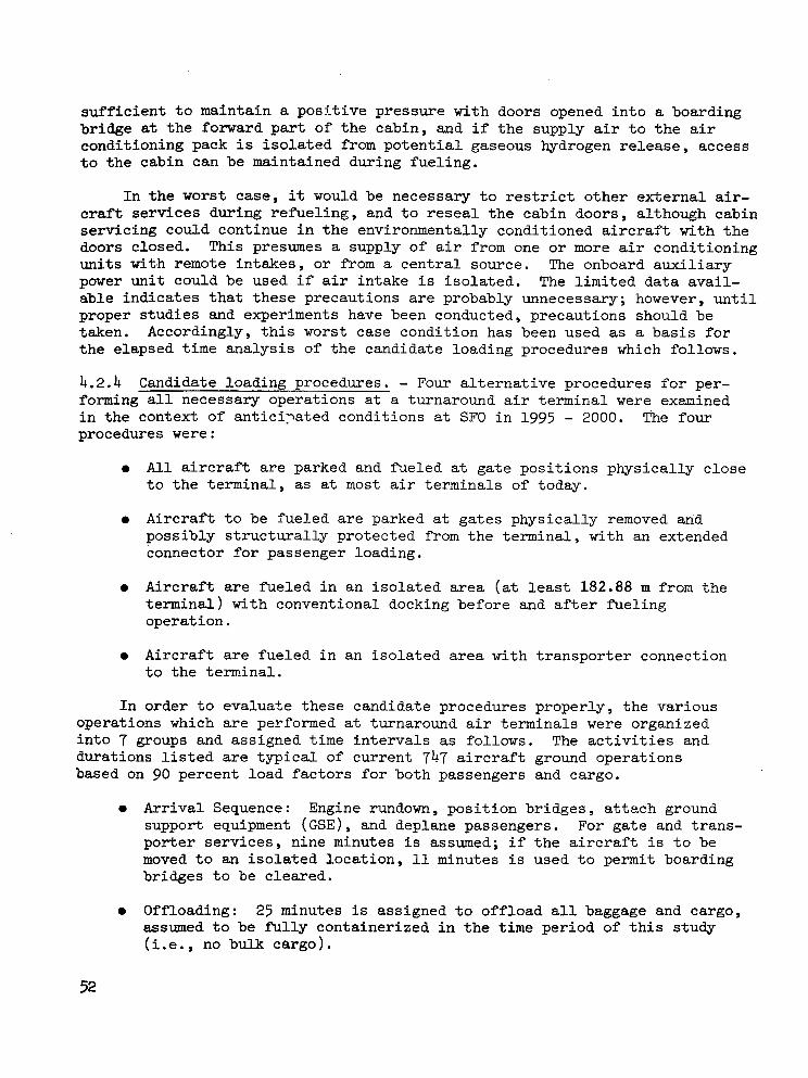
sufficient to maintain a posltive pressure with doors opened into a boarding bridge at the forward part of the cabin, and if the supply air to the air conditioning pack is isolated from potential gaseous hydrogen release, access to the cabin can be maintained during fueling.
In the worst case, it would be necessary to restrict other external air- craft services during refueling, and to reseal the cabin doors, although cabin servicing could continue in the environmentally conditioned aircraft with the doors closed. This presumes a supply of air from one or more air conditioning units with remote intakes, or from a central source. The onboard auxiliary power unit could be used if air intake is isolated. The limited data avail- able indicates that these precautions are probably unnecessary; however, until proper studies and experiments have been conducted, precautions should be taken. Accordingly, this worst case condition has been used as a basis for the elapsed time analysis of the candidate loading procedures which follows.
4.2.4 Candidate loading procedures. - Four alternative procedures for per- forming all necessary operations at a turnaround air terminal were examined in the,context of antici7ated conditions at SF0 in 1995 - 2000. The four procedures were :
0 All aircraft are parked and fueled at gate positions physically close to the terminal, as at most air terminals of today.
0 Aircraft to be fueled are parked at gates physically removed and possibly structurally protected from the terminal, with an extended connector for passenger loading.
0 Aircraft are fueled in an isolated area (at least 182.88 m from the terminal) with conventional docking before and after fueling operation.
0 Aircraft are fueled in an isolated area with transporter connection to the terminal.
In order to evaluate these candidate procedures properly, the various operations which are performed at turnaround air terminals were organized into 7 groups and assigned time intervals as follows. The activities and durations listed are typical of current 747 aircraft ground operations based on 90 percent load factors for both passengers and cargo.
0 Arrival Sequence: Engine rundown, position bridges, attach ground support equipment (GSE) , and deplane passengers. For gate and trans- porter services, nine minutes is assumed; if the aircraft is to be moved to an isolated location, 11 minutes is used to permit boarding bridges to be cleared.
0 Offloading: 25 minutes is assigned to offload all baggage and cargo, assumed to be fu l ly containerized in the time period of this study (i.e., no bulk cargo).
52


Figure 13. San Francisco In t e r - na t iona l A i rpo r t , 1985 Plan
53
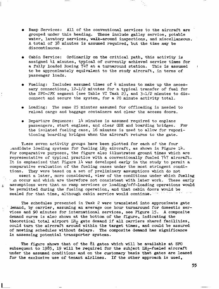
0 Ramp Services: All of the conventional services to the aircraft are grouped under this heading. These include galley service, potable water, lavatory services, walk-around inspections, and miscellaneous. A total of 38 minutes is assumed required, but the time may be discontinuous.
0 Cabin Service: Ordinarily on the critical path, this activity is assigned 41 minutes, typical of currently achieved service times for a fully loaded Boeing 747 at a turnaround station. This is assumed I to be approximately equivalent to the study aircraft, in terms of passenger loads.
0 Fueling: Includes assumed times of 4 minutes to make up the neces- sary connections, 12-1/2 minutes for a typical transfer of fuel for the SFO-JFK segment (see Table VI Task 2), and 3-1/2 minutes to dis- connect and secure the system, for a 20 minute activity total.
0 Loading: The same 25 minutes assumed for offloading is ne.eded to reload cargo and baggage containers and clear the access doors.
0 Departure Sequence: 14 minutes is assumed required to enplane passengers, start engines, and clear GSE and boarding bridges. For the isolated fueling case, 16 minutes is used to allow for reposi- tioning boarding bridges when the aircraft returns to the gate.
Tlrese seven activity groups have been plotted for each of the four Landidate loading systems for fueling LH2 aircraft, as shown in Figure 14. For comparative purposes, the figure also illustrates ground times which are representative of typical practice with a conventionally heled 747 aircraft. It is emphasized that Figure 14 was developed early in the study to permit a comparative evaluation of the fueling cases under the most stringent condi- tions. They were based on a set of preliminary assumptions which do not
.esent a later, more considered, view of the conditions under which fueling ' ' An occur and which are therefore not consistent with later work. These early
8 . assumptions were that no r'amp services or loading/off-loading operations would be permitted during the fueling operation, and that cabin doors would be sealed for that time, although cabin service would continue. ' . ' . " . ' . " '
The schedules presented in Task 2 were translated into approximate gate iemand, by carrier, assuming an average one hour turnaround for domestic ser- vices and 90 minutes for international services, see Figure 15 . A composite demand curve is also shown at the bottom of the figure, indicating the theoretical total airport LH2 gate demand if all carriers shared facilities, could turn the aircraft around within the target times, and could be assured of meeting schedules without delays. Tne composite demand has significance in assessing potential transporter systems.
The figure shows that of the 81 gates which will be available at SF0 subsequent to 1985, 19 will be required for the subject LH2-fueled aircraft under the assumed conditions and on the customary basis that gates are leased for the exclusive use of tenant airlines. If the other approach is used,
55
I

A R R I V A L S E O U E N C E
O F F L O A D I N G
R A M P S E R V I C E S
C A B I N S E R V I C E
F U E L I N G
L O A D I N G
D E P A R T U R E S E Q U E N C E
AR.RlVAL
O F F L O A D I N G S E Q U E N C E
R A M P SERVICES
C A B I N S E R V I C E
F U E L I N G
L O A D I N G
D E P A R T U R E S E O U E N C E
A R R I V A L
O F F L O A D I N G
R A M P S E R V I C E S
C A B I N S E R V I C E
F U E L I N G
L O A D I N G
D E P A R l U R E
S E O U E N C E
S E O U E N C E
A R R I V A L S E O U E N C E
O F F L O A D I N G
R A M P S E R V I C E S
C A B I N S E R V I C E
F U E L I N G
L O A D I N G
D E P A R T U R E S E Q U E N C E
ELAPSED TIME IN MINUTES 10 2 0
I eO"7-0 8 0 0,O 1 y O 1 i 0 l l P O
CONVENTIONAL AIRCRAFT I 1==11 I
I 1
I ! I 1 1 V P l C A L 7 4 7 T U R N A R O U N D
1
I LH2 AIRCRAFT G A T E R E F U E L I N G
( A L T E R N A T I V E S N O . 1 & 2) I
i I m m m m ~ m m m ! I
I 4 - l I
I1I111L111d1
I I
LH2 AIRCRAFT
-I I S O L A T E D R E F U E L I N G
lmmll,m~mllmmmlmmml ( A L T E R N A T I V E N O . 3)
i 1 I - ~ = = - - ~ - ~ ~ I1 ! 1 1 1 1 1 1 1 1 1 1
R E L O C A T E A I R P L A N E -
LH2 AIRCRAFT T R A N S P O R T E R
( A L T E R N A T I V E N O . 4)
1111 D m 1 1
.I 11111111. m
1 1
Figure 1 4 . Comparison o f A l t e rna te Ground Handling Procedures

TIME OF D A Y
i 4 0 8 10 1200 . 14 16 18 2 0 22- 2aOO L H 2 Q A T E S LEASED GATES: ' (NOON) 1
0 W A 1
i I ! 1
I DL 1
I N A 1
LI I 0
.I :
'. 3 . 2
I t
,O
. i I
P A 3 ! r. - - . . ?
I . . i 2
i !l " I
I j 0 N W 2
I3
1' I
I
- 0
UA 3
A A 3
TW 6
19 G A T E S R E Q U I R E D
10 GATES REQUIRED
"
57

i.e., if the carriers share gate facilities, only 10 gates would be needed to serve the needs of the LH2 aircraft at SF0 in 2000 A.D. Although this reduction from 19 to 10 gates would represent a significant saving it must be realized that the saving would be temporary since more LH2 aircraft will be put in service in succeeding years. The shared gate approach is a good candidate for those airports which are short of space for terminal facilities. However, since SF0 is runway critical, the leased gate approach is used as a basis for the LH2 requirements analysis.
As previously described, the alternatives for fueling include: 1) at conventional gates, as now; 2) at conventional gates but physically removed and boarded through an extended connector; 3) at an isolated location, with enplaning, deplaning, and servicing performed at conventional gates, moving the aircraft before and after fueling; and 4) at an isolated gate location with a version of transporter for enplaning and deplaning.
The physical constraints at SF0 militate against Alternative No. 2. It is not possible to provide significant physical separation of aircraft from the passenger terminal without major reconstruction of the terminal area.
Alternative No. 3 yielded a turnaround time of about 2 hours for trans- rontinental services as shown in Figure 14. The only feasible locations for remote refueling at SF0 are 2682 m (8800 feet) from the gates. These are areas which could be developed by land reclamation in the seaplane basin, or in the area south of the runway intersections (see Figure 13). The distance of 2682 m (8800 feet) assumes movement around the runways. Although cross runway movement is possible, the delays would.probably eliminate the time benefits of the. shorter distance. As shown in Figure 14, 5 minutes has been assigned for moving the aircraft to/from the terminal gate. It was assumed the aircraft would be moved without the use of the aircraft engines by utilizing a high speed tractor capable of towing aircraft at speeds of 48-56 km (30-35 mph) (References 8 and 9 ) . Allowing for maneuvering of aircraft into and out of gate positions and fueling stands, an average speed of 32 km (20 mph) has been assumed for the aircraft relocation. The loading/ offloading sequences are on the critical path, along with the fueling opera- tion. , If the assumed restriction against services during f’ueling was lifted, this time would be shortened somewhat. However, this would mean marshalling and handling cargo-containers at the isolated location and result in long hauls’ from the cargo complex to the refueling area. It would be necessary, in any .case, to offload and reload baggage containers at the gate to avoid long delays in preloading containers and bag retrieval. This function often uses equipment and labor common to the cargo container handling f’unction, so duplication of equipment and effort would be required. In all probability, all offloading and loading would be performed at the gate, despite the turn- around penalties.
The ramp services were charted as being performed at the isolated location in order to permit cabin service to begin prior to completion of other ramp services. This again suggests duplication of equipment and labor, as the terminal gates must be served in any case. Further, a sizeable
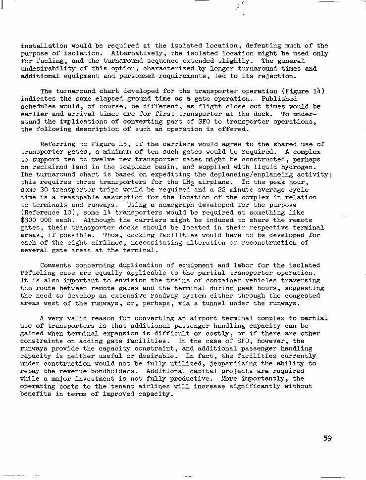
installation would be required at the isolated location, defeating much of the purpose of isolation. Alternatively, the isolated location might be used only for fueling, and the turnaround sequence extended slightly. The general undesirability of this option, characterized by longer turnaround times and additional equipment and personnel requirements, led to its rejection.
The turnaround chart developed for the transporter operation (Figure 14) indicates the same elapsed ground time as a gate operation. Published schedules would, of course, be different, as flight close out times would be earlier and arrival times are for first transporter at the dock. To under- stand the implications of converting part of SF0 to transporter operations, the following description of such an operation is offered.
Referring to Figure 15, if the carriers would agree Lo the shared use of transporter gates, a minimum of ten such gates would be required. A complex to support ten to twelve new transporter gates might be constructed, perhaps on reclaimed land in the seaplane basin, and supplied with liquid hydrogen. The turnaround chart is based on expediting the deplaneing/enplaneing activity; this requires three transporters for the LH2 airplane. In the peak hour , some 30 transporter trips would be required and a 22 minute average cycle time is a reasonable assumption for the location of the complex in relation to terminals and runways. Using a nomograph developed for the purpose (Reference lo), some 14 transporters would be required at something like $300 000 each. Although the carriers might be induced to share the remote gates, their transporter docks should be located in their respective terminal areas, if possible. Thus, docking facilities would have to be developed for each of the eight airlines, necessitating alteration o r reconstruction of several gate areas at the terminal.
, '
Comments concerning duplication of equipment and labor for the isolated refueling case are equally applicable to the partial transporter operation. It is also important to envision the trains of container vehicles traversing the route between remote gates and the terminal during peak hours, suggesting the need to develop an extensive roadway system either through the congested areas west of the runways, or, perhaps, via a tunnel under the runways.
A very valid reason for converting an airport terminal complex to partial use of transporters is that additional passenger handling capacity can be gained when terminal expansion is difficult or costly, or if there are other constraints on adding gate facilities. In the case of SFO, however, the runways provide the capacity constraint, and additional passenger handling capacity is neither useful or desirable. In fact, the facilities currently under construction would not be fully utilized, jeopardizing the ability to repay the revenue bondholders. Additional capital projects are required while a major investment is not fully productive. More importantly, the operating costs to the tenant airlines will increase significantly without benefits in terms of improved capacity.
59

For these var ious reasons convent ional terminal gate refuel ing was se lec ted for eva lua t ion . In addi t ion , s ince the s e l e c t e d a i r p o r t is similar t o many ex i s t ing l a rge hubs with elements of l i n e a r , p i e r , and satel l i te te rmina ls , se lec t ion of the gate ref 'ueling system affords the advantage t h a t t h e results w i l l r e p r e s e n t t h e t e c h n i c a l f e a s i b i l i t y and cos t s of implementing a convent ional refuel ing system for a t y p i c a l a i r p o r t , u s i n g ground systems common t o J e t A f u e l e d a i r c r a f t .
4.2.5 Evaluat ion of external tank a i rcraf t concept . - While the foregoing discussion has been directed pr imari ly toward considera+, ion of the, in ternal tank a i rplane design, the implicat ions of the ex te rna l t ank concept (Refer- ence 2 ) i n terms of the ref 'ueling operation have also been considered. Since s ingle po in t re fue l ing i s poss ib le wi th e i ther a i rp lane conf igura t ion , the two a i r c r a f t are not viewed as be ing rad ica l ly d i f f e r e n t i n terms of the recommended terminal gate ref 'ueling procedure (Section 4 .5 ) .
The external tank concept , however , offers the potent ia l for a unique system of ref'ueling i n t h a t a tank system could conceivably be developed wherein the tanks could be demounted f o r r o u t i n e r e f u e l i n g and defueling. It i s assumed t h a t t h i s a c t i v i t y would not be performed a t the t e rmina l ga te bu t would require es tabl ishment of an a d d i t i o n a l s t a t i o n where t h e a i r c r a f t would stop for quick disconnect removal of tanks before proceeding to the gate . Upon complet ion of gate services , the depart ing a i rcraf t would r e t u r n t o t h e fue l ing s ta t ion for remount ing of f u l l LH2 tanks,
From an opera t iona l s tandpoin t , the re fue l ing s ta t ion should idea l ly be loca ted so t h a t a d d i t i o n a l t a x i (or a i r c ra f t t owing) d i s t ances are h e l d t o a minimum. However, the physical and s i t e cons t r a in t s at SF0 would probably requi re tha t th i s fac i l i ty be loca ted such tha t e i ther ex t remely long taxi distances or cross runway movement would be required. Other disadvantages of the system are that the s tops for disconnect and reconnect of the tanks would requi re ex t ra t ime, there would be an i n e v i t a b l e a i r c r a f t t r a f f i c problem at the tank removal s ta t ion, the quick disconnect requirements of the system would i n t r o d u c e r e l i a b i l i t y and maintenance problems i n t h e cryogenic fuel feed system, and the concept would require extra handl ing equipment and purchase of spare t anks . Cons ider ing these fac tors , the external tank a i rplane concept does not appear to offer advantages in terms of a re fue l ing procedure appropr ia te for SFO.
4.2.6 System descr ip t ion . - Locations of the 19 ga te s s e l ec t ed for t h e LH2 service concept are i l l u s t r a t e d i n F i g u r e 16. Xn o rde r t o pe rmi t maximum g a t e u t i l i z a t i o n , it i s assumed t h a t Jet A f u e l w i l l cont inue to be provided t o t h e s e same ga te s .
60

I
\ by darkened aircraft symbols. p_
Figure 16. Gates With LH Services 2
61

The reference LH2-fueled in t e rna l - t ank a i r c ra f t is configured with the m2 fill connect point located in the t a i l cone of the fuselage. The tank vent piping i s r o u t e d t o t h e t o p of t h e v e r t i c a l s t a b i l i z e r a n d GH2 is vented t o atmosphere during flight and when t h e a i r c r a f t i s parked a t the ga t e , except during the fueling operation. During fueling, the LH2 tank vent will be routed t o a second connect point at t h e t a i l by means of a d i v e r t e r valve.
A t each ga te fue l ing s ta t ion the hydrant cons is t s o f an LH2 valve and a GH2 vent co l lec t ion valve. These hydrant valves and t h e i r i n t e r f a c e con- nec t ions . a re in a p i t l o c a t e d so as t o be s i t ua t ed below t h e t a i l of the parked a i rc raf t . The p i t i s normally covered with a load-bearing grating. The LH;i valve i s connected to a vacuum jacke ted header for recyc le to the s torage and l i q u e f a c t i o n f a c i l i t y . The GH2 v e n t c o l l e c t i o n l i n e r e t u r n s t h e cold gaseous hydrogen t o t h e l i q u e f a c t i o n p l a n t .
The fue l ing opera t ion w i l l be carr ied out by a hydrant fueler vehicle equipped to p rov ide a l l necessary interfaces between the hydrant and t h e a i rc raf t sys tems. A concept for the hydrant fueler i s i l l u s t r a t e d , i n Fig- ure 17. Flex hose connections w i l l be made from the hydran t t ruck t o t he LH2 and vent valves in the pi t . Simultaneously, a cherry picker type boom i s r a i s e d t o t h e a i r c r a f t t a i l cone where jacke ted f lex hoses a re mated t o t h e a i r c r a f t LH2 and vent connect points. The hoses mated t o t h e p i t h y d r a n t s and t o t h e a i r c r a f t a r e i n t e r c o n n e c t e d by vacuum jacketed piping on t h e f u e l e r truck, complete with valves and instruments. The hydrant fueler t ruck will carry a vacuum pump, high pressure hel ium bot t le and the necessary valves and controJs to permit purification ( the removal of a11 t races o f a i r and moisture) of the f lex hoses pr ior to the intro 'duct ion of hydrogen. This sys- t e m will a l so pe rmi t t he f l ex hoses t o be i ne r t ed after fue l ing and p r i o r to disconnect ion.
Once t h e LH2 and vent hoses have been connected, purified, and proofed (a helium pressure check of the connect points) , the hydrant LH2 and GH2 vent valves w i l l be opened. , A b leed va lve loca ted ins ide the a i rc raf t on t h e LH2 l ine nea r t he f i l l va lve and rou ted to the vent w i l l be opened t o c h i l l down the fueler t ruck piping and hoses , as w e l l as a por t ion o f t he a i r c ra f t f i l l l i n e s . The a i r c r a f t fill valve w i l l then be opened and the tanks f i l l ed . This procedure minimizes addition' of heat t o t h e LH2 which remains i n t h e air- c r a f t f u e l tanks from the p rev ious f l i gh t .
A t the conclusion of the fillir., ope ra t ion t he a i r c ra f t va lves and t h e hydrant valves will be closed and the hoses kill be i n e r t e d p r i o r t o d i s - connection. The helium used for inerting both before and after the fue l ing operation will be vented into the hydrogen vent gas col lect ion header and r e c y c l e d t o t h e l i q u e f a c t i o n f a c i l i t y where it is separated from t h e hydrogen as a normal function of the liquefaction process. A large f l ract ion of t h e helium can therefore be recyc led for reuse in the hydrant fuelsr truck and similar funct ions,

Figure 1 7 . LH -Hydrant Fueling-Truck Concept 2

of aircraft which have been out of service for an extended period, e.g., coming from major overhaul at the maintenance facilities, will be performed at a fueling point adjacent to the LH2 storage facility (see Figure 31 in section 5.1). Several aircraft can be accommodated at these stands , which also serve as a defueling area for aircraft that are to be out-of-service for an extended period.
The refueling operation as described is considered to be a technically feasible concept which can be performed without significantly altering cur- rent procedures for servicing aircraft at existing terminal gates. A more detailed description of the refueling system is presented in Task 7.
4.3 Task 5: Hydrogen Storage Evaluation
The primary objective of this task is to determine the type of container best suited to the storage of large quantities of liquid hydrogen at SFO. The types of containers which were studied include vacuum insulated double wall tanks using both powder insulation and multiple radiation shields, and non- vacuum foam-insulated single. wall tanks. The performance and economics of each type of tank are examined and used as a basis for selection of the pre- ferred tank. The merits of underground vs aboveground tanks are compared.
Task 5 objectives also include a determination of the capacity of the total storage facility, as well as the number and capacity of the individual tanks in the facilitv.
4.3.1 Tank farm requirements. - Liquid hydrogen storage tanks must be pro- vided in adequate number and of sufficient capacity to serve two major functions.
a. To provide dispensing and receiving containers to service the air- craft fueling system and to receive the liquid hydrogen product as it is produced from the hydrogen liquefiers.
b. To provide backup capacity in order that fueling operations can con- tinue in the event of outage of the liquefaction equipment o r inter- ruption of the feedstock (GH2) supply.
A minimum of three tanks is required for dispensing and receiving operations. One tank is used for dispensing, which requires that it be slightly pressurized to obtain sufficient NPSH for the dispensing pump which feeds LH2 into the fueling circuit. The second tank is used for receiving liquid from the hydrogen liquefiers as well as excess liquid returned from the fueling circuit or from defueling of aircraft. This tank must operate at essentially atmospheric pressure so that in the subsequent dispensing phase of fueling, liquid hydrogen is delivered to the aircraft fuel tanks with maximum subcooling. The third tank serves as a full standby tank which can be pressurized to be ready for immediate switchover to dispensing service at the moment the dispensing tank becomes empty. The need for the full standby tank results from the near impossibility of scheduling receiving and dispensing
64

operat ions in such a way t h a t a n empty dispensing.tank and a full receiving tank occur simultaneously. A th ree t ank sys tem provides the ,necessary '
f l e x i b i l i t y i n o p e r a t i o n s and p e h i t s decoupling of storage tank f i l l ing and emptying operations from aircraft fueling schedules.
Suf f ic ien t s torage capac i ty i s provided t o permi t un in te r rupted a i rc raf t fue l ing fo r a one-day per iod in event of to ta l ou tage o f a l l fou r l i que fac t ion modules. Task 2 places average daily consumption, for peak months in t he yea r . 2000, at 696 700 kg (768.0 t o n s o r 2 600 000 ga l lons ) . I n the f ina l conf igu- r a t ion o f t he s to rage f ac i l i t y , a t least 11 356 m3 ( 3 000 000 ga l lons ) a r e he ld i n r e se rve a t a l l times which provides 27.7 hours of backup during peak month operation or 38.0 hours of backup during off-peak, normal operation. The 11 356 m3 ( 3 000 000 ga l lons ) are con ta ined i n t h ree 3786 m3 (1 000 000 ga l lon) t anks , one of which i s t h e fu l l standby tank of the 3-tank receiving- dispensing set and the o the r two are used for s torage purposes only. The to ta l t ank fa rm w i l l therefore cons is t o f f ive 3785 m3 (1 000 000 ga l lon ) tanks.
4.3.2 Underground vs aboveground tanks. - Underground ins t a l l a t ion o f t he s torage tanks at SF0 has been re jected.because of inappropriate soi l con- dit ions. There i s very l i t t l e e l e v a t i o n above the surface of San Francisco Bay so t h a t an underground i n s t a l l a t i o n would l o c a t e most of the s torage tank below the water t ab le l eve l . E labora te cons t ruc t ion would be r e q u i r e d t o
. maintain physical in tegri ty of the tank as wel l as good thermal performance. However, i n t h e i n t e r e s t s of completeness i n t h i s discussion, the meri ts of underground tanks are examined quali tatively.
-_____
A tank des ign su i tab le for LH2 se rv ice must provide a high level of thermal performance. The large temperature difference between the tank contents and i t s surroundings, and the low l a t en t hea t of vaporization of hydrogen combine t o produce an unsat isfactor i ly high evaporat ion ra te for the LH2 for a l l but the h ighes t qua l i ty insu la t ion sys tems. For t h i s reason, the frozen-earth type of underground storage tank which has been used for lique- f i ed na tu ra l gas (LNG) s torage would not be sui table . Other than the excessive loss of LH2 r e s u l t i n g from cooldown of the surrounding earth, l iquefact ion and f reezing of a i r from the surroundings w i l l a lso occur as it diffuses through the ground toward the cold vessel w a l l . This p resents a safety hazard as r ec t i f i ca t ion o f t he a i r w i l l t end t o occu r , w i t h pref- e r en t i a l vapor i za t ion of t h e more v o l a t i l e n i t r o g e n and concentration of oxygen i n t h e r e s i d u a l l i q u i d . The oxygen-enriched liquid upon encounter with combu.stile material w i l l be po ten t ia l ly explos ive . An acceptable insulat ion system must therefore inc lude an imperv ious bar r ie r to the d i f fus ion of air toward the w a l l o f t he l i qu id con ta ine r .
The only mtisfactory underground tank, therefore , would be a double-wall vacuum insu la ted t ank . The advantage in locat ing this tank underground i s only t o lower the t ank prof i le or t o remove it e n t i r e l y as an obs t ruc t ion t o f l i g h t t r a f f i c . This should only be done as required; i f spec i f ied c learances can be maintained with aboveground tanks, t h e r e i s economic advantage in aboveground i n s t a l l a t i o n .

I 1 I I1 I I1 l11ll11111l11l11l1111lll1111l1111l11111l111l1l11
1 4.3.3 Vacuum insulated double wall tanks
4.3.3.1 Powder insulation. - This tank configuration consists of a cold inner liquid container, a warm outer container, and an evacuated annulus which is filled with a powder insulation, typically perlite. The shape is usually spherical which gives a minimum surface area per unit of contents and helps to minimize heat leakage. This design is the commercially accepted standard in the liquid hydrogen industry and is hereby recommended for use in this study.
Tank specifications are listed in Table XV. Materials of construction would be typically carbon steel for the warm shell and austenitic stainless steel for the liquid container. Vacuum in the insulation space is maintained at 13.30 Pa (100 microns) or less which results in an effective thermal conductivity of no greater than 2.6 W/m-K (1.5 x 10⁻³ Btu/hr-ft-R) . The resulting net evaporation rate is 0.06% of tank contents per day or 1.86 x 10⁻³ kg/s (354 lb/day) for the 3785 m3 (1 000 000 gal) tank.
4.3.3.2 Multilayer insulation. - This tank configuration is the same as that for the powder insulation except that the powder is replaced by a multilayer insulation consisting of alternate layers of low emissivity metal foil (usually aluminum) and a thin, low conductance spacer (usually glass fiber paper). The vacuum integrity required of the two vessels must be of higher order than those used with vacuum perlite insulation due to the greater sensitivity of the multilayer thermal conductivity to pressure. A vacu1m of 0.0133-0.266 Pa (0.1-2.0 microns) must be maintained.
TABLE XV SPECIFICATIONS: LIQUID HYDROGEN STORAGE TANK VACUUM POWDER INSULATION
I I I Customary SI
Capacity I 3 785 m3 (1 000 000 gallons ) 267 600 kg ( 590 000 lbs )
Working pressure 1 205 w a 1 Outer tank O.D.
Spherical Configuration
Vacuum perlite Insulation
0.06% per day Net evaporation rate
(66 ft) 20.1 m Inner tank O.D.
(71 ft) 21.6 m
66

The s p e c i f i c a t i o n s f o r t h i s t y p e o f t a n k are l i s t e d i n Table X V I . The net evaporation rate at the optimized 24.1 cm (9.5 in ) i n su la t ion t h i ckness amounts t o 0.028% pe r day which is about half that fo r t h e vacuum p e r l i t e insu la t ion . The result ing hydrogen loss amounts t o 8.77 x 10⁻⁴ kg/s (167 lb/day) .
The tank i s f i e l d e r e c t e d and t h e i n s u l a t i o n i s ins t a l l ed a f t e rward so tha t t he ou te r she l l p rov ides p ro t ec t ion aga ins t t he wea the r . The 0.762 m (2.5 f t ) yide annulus between the i nne r tank and outer she l l p rovides enough room for workmen to app ly shee t s o f t he mu l t i l aye r i n su la t ion t o t he ou te r sur face o f the inner tank. Access t o t h e i n s u l a t i o n s p a c e is provided by a manway i n t h e o u t e r s h e l l which i s sealed with a welded-on cover after i n s t a l l a t i o n is complete. This insulation system was r e j e c t e d i n t h e f i n a l s e l e c t i o n f o r economic reasons and because of the sensi t ivi ty of i t s thermal performance t o s l i g h t changes i n vacuum.
4.3.4 Insu la ted s ing le w a l l tanks. - Single wall tanks always present the des igne r w i th t he a t t r ac t ion t ha t t he ou te r she l l , and i t s a t tendant cos t , i s eliminated. The s impl i f i ca t ion , however, makes a high level of thermal performance more d i f f i cu l t t o ach ieve because t he re i s no simple way t o apply a vacuum insulation. Consequently, enhanced performance must be achieved by an increase i n insu la t ion th ickness .
The in su la t ion app l i ed t o a tank in l iqu id hydrogen se rv ice p resents the additional problem of excluding air from the i n su la t ion . A s desc r ibed i n t he sec t ion on underground tankage, unless a completely impervious coating i s
TABLE XVI SPECIFICATIONS: L I Q U I D HYDROGEN STORAGE TANK MULTILAYER INSULATION
i Capacity
Working pressure
Outer tank O.D.
Inner tank O.D.
Insu la t ion th ickness
Net evaporation rate
Insu la t ion
Configuration
SI
3 785 m3 267 600 kg
205 kPa
21.6 m
20.1 m
24.1 cm
Customary
(1 000 000 gal lons) (590 000 l b )
0.028% per day
Vacuum multilayer
Spherical

applied to the surface, air will diffuse through the insulation space toward the cold tank wall, condensing and freezing as the temperature decreases to that of LH2. Not only will the thermal conductivity of the insulation system be compromised by such action but also the physical integrity will be destroy- ed. The structure of closed-cell foams, for example, will be damaged and if sufficient frozen air accumulates at the tank wall, sections of insulation can be blown off, even violently, upon tank warm up as the frozen air vaporizes.
Mindful of the preceding advantage and limitations, a single rrall tank is examined (Table XVII) which features a sprayed-on polyurethane foam insulation. This material has a thermal conductivity of 0.012 Wjm-K (0.007 Btu/hr-ft-R) at a density of 40 kg/m3 (2.5 lb/ft3). A thickness of 1.07 m (3..5 ft ) provides near-optimum performance. Wire mesh reinforcement is assumed to be required for every 0.305 m (1 ft) of insulation thickness .for structural strength. A vapor barrier of butyl rubber is applied to the outer surface topped off with a noncombustible layer for fireproofing. This insulation is assumed to have a useful life of 10 years, which may be optimistic. At such time, the insu- lation must be removed and replaced. This type of insulation syst,em was rejected in the final selection for economic reasons and because of unproven performance.
4.3.5 Economic comparison. - An economic comparisoh was made between the vacuum perlite, .the multilayer, and the single wall 5nsulation systems on a present value basis which includes tank investment and cost of evaporation loss as cost elements. Evaluation of the evaporation cost is based on 'locat- ing the storage tanks at the airport site and that the evaporated hydrogen is recoverable for.-reliquefaction. Therefore, only the cost of liquefaction, at a unit value of 42 .Od/kg (19.05d/lb) of hydrogen, was incurred. (Ref. 7)
TABLE XVII. SPECIFICATIONS: LIQUID HYDROGEN STORAGE TANK SINGU WALL - FOAM INSULATION
SI Customary
Capacity (1 000 000 gallons) 3 785 m3 267 600 kg ( 590 000 lb )
Working pressure
Spherical Configuration
Polyurethane foam Insulation
0.344% per day Net evaporation rate
(3.5 ft) 1.07 m Insulation thickness
(66 ft) 20.1 m Inner tank O.D.
(15 wig) 205 kPa
68

Capital investment for vacuum perlite insulated.spherica1 liquid hydrogen storage tanks, including installation, is shown on Figure 18. The cost capacity curve is seen. to be linear with a slope of $1055 per m3 ($4/gal) of capacity. A 3785 xu3 (1 000 000 gal) storage tank will cost $4 000 000. .This is the largest c’apacity tank which has been built for LH2 service. Because of the absence of economic advantage with increasing capacity, there is consider- able freedom to select the number and size of the storage tanks based on other factors. A maximum capacity tank will result in the lowest evaporation loss per unit of capacity, the least site area and the minimum complexity in pump- ing and manifolding the storage tanks to the fueling circuit. Considerations of site limitations, backup requirements and the need for at least three separate tanks for fueling operations lead to the selection of the 3785 m3 (1 000 000 gal) capacity tank for use at the SF0 site.
Table XVIII and Figure 19 both present an economic comparison between the three types of insulation systems for the 3785 m3 (1 000 000 gal) tank. As expected, the single wall foam-insulated tank has the lowest investment and the multilayer-insulated tank has the highest. The converse is true of the annual evaporation cost. A sizeable expense is incurred for the replacement of the foam insulation, half of it occurring after 10 years and the other half after 20 years. This is assumed to be an operating expense. The present value of the replacement cost is quite low, however, because the expense is incurred sb far in the future. It is the experience of the cryogenics industry that maintenance cost on double wall, vacuum insulated tanks is essentially nil.
The economic choice- is the vacuum perlite insulation system which exhibits 3 percent advantage over the single wall tank and a 7 percent advan- tage over the multilayer system. The multilayer-insulated tank is the only serious contender to the vacuum perlite insulated tank as a proven system. The single wall tank cannot be seriously considered as a viable alternate at this time because the performance and physical integrity of its foam insulation system has not been proven, the factors assumed herein being some- what conjectural. The vacuum perlite insulation has a lower initial invest- ment than the multilayer type; however, the thermal performance is not nearly as good, resulting in a more-than-double evaporation cost. This advantage of the multilayer system would disappear with a slight loss of vacuum because of the sensitivity of this system to pressure. An increase to 1.33 Pa (10 microns) of pressure could more than dissipate the thermal advantage of the multilayer insulation over the vacuum perlite. For reasons of proven perfor- mance, simplicity, reliability and cost, the vacuum perlite insulation system selected for use in this analysis of airport requirements.
4.4 Task 6 : Hydrogen Liquefaction
Task 3 (Section 4.1) results clearly showed the economic advantage of locating the liquefaction facility at the airport site. Such location is contingent, of course, upon the availability of the necessary land area at the airport. This task addresses itself to that question. Plant layouts are developed for a central liquefaction complex large enough to supply the liquid

5 .O
4.0'
3.0 0
H d
I
0 0 2.0
A
e3
kl
0 200 400 600 800
/
TANK CAPACITY - loo0 gallons
I I I 1 I I ~ ~~~
0 I
lo00 2000 3000 4000
TANK CAPACITY - rn3
Figure 18. Cost of Spherical Double Wall Vacuum P e r l i t e Insulated Liquid Hydrogen Storage Tanks

TABLE XVIII. ECONOMIC COMPARISON LIQUID HYDROGEN STORAGE TANKS
Capacity = 3785 m (1 000 000 gal) 3
Investment
tvaporation rate, kg/s
hnual evaporation cost
Insulation replacement
?resent value
Investment
Evaporation cost
Insulation Replacement
Total
~
I1 Vacuum Perlite
$4 000 000
1.86 x
$ 24 610
" " _
$3 838 000
$ 103 000
" " _ $3 941 000
ulation Syste Vacuum
Multilayer
$4 387 000
8.77 x
$ 11 610
" " _
$ 4 210 000
$ 49 000
" " _ $4 259 000
Single Wall Foam
$3 553 000
1.07 x
$ 141 000
$ 625 000
$3 409 000
$ 591 000
$ 69 ooo
$4 069 ooo

4 . 5 1
POWDER MULTI- SINGLE SHIELDED WALL
V
DOUBLE WALL EVACUATED
INSULATION REPLACEMENT
PRODUCT LOSS
INVESTMENT
Figure 19.. Cost of Three Ty-pes of Liquid Hydrogen Storage Tanks

hydrogen requirements as determined in Tasks 2 and 3 and also for a single- module liquefier for 6apacity expansion purposes. In addition, necessary sitigg arrang'ements and construction practices for safe installation arid operhtion of the liquefaction plant are considered and presented.
4.4.1 Liquefaction facility requirements. - Establishing the capacity of the liquefaction facility was the first task faced. The facility must be suffi- ciently large to provide not only for the block fuel requirements to the engines but also for the losses incurred in f'ueling operations as described in Task 7 . Sufficient capacity must also be provided to meet the needs of peak-month operations. Peak requirements are expected to increase about 37 percent over average capacity during off-peak month operation in the year 2000 (Task 2.).
Task 2 places peak month block fuel requirements at 7.68 kg/s (731.4 tonslday). Loss analysis presented in Task 3 predicts a 12.2 percent loss in refueling operations and a 3.2 percent loss for the more optimistic method of tank operations, giving a combined loss of 15.7 percent between LH2 in storage to LH2 delivered as fuel to the engines, including the l o s s due to boiloff in the aircraft tanks. Liquefaction capacity during peak months must, therefore, be 8.886 kg/s (846.2 tons/day) .
It has been shown (Reference 7) that the largest hydrogen liquefaction mddule that can be economically justified has a capacity of 2.625 kg/s (250 tons/day). Therefore, it was decided the liquefaction facility at SF0 would use four production modules of this capacity. This provides for a maximum output of 10.5 kg/sec (1000 tons/day) which is 1 8 percent in excess of peak demand and 62 percent in excess of average demand during off-peak operations. These requirements are, however, based on fueling losses from the optimum method of tank operations (Method #1 from Task 3 ) . Based on the least efficient method of tank operations (Method # 2 ) , liquefaction require- ments are 9.483 kg/s (903.2 tons/day) for peak month operation and 6.912 kg/s (658.3 tons/day) for average off-peak operation. The four liquefaction modules therefore provide a 10.7 percent margin in production capacity over the maximum conceivable demand situation.
4.4.2 Liquefaction facility description. - The 10.5 kg/sec (1000 tons/day) total liquefaction capacity is provided by four identical modular units. Figure 20 is a schematic diagram which illustrates the f low of the lique- faction process. A plot plan which shows the equipment arrangement is presented in Figure 21.
Impure gaseous hydrogen feedstock, having a hydrogen purity of about 96.6 percent and containing nitrogen, carbon monoxide, carbon dioxide, and methane as impurities, is distributed from the feedstock pipeline to the first stage of the four reciprocating hydrogen feed compressors. The feedrate required to produce the 8.888 kg/s (846.5 tons/day) peak month LH2 product rate is 453 100 m3/h (16. OxlOE SCFH) . The compressed gas is then purified cryogenically to yield an extremely pure hydrogen gas which is then boosted to 4137 kPa (600 psia) in the secone stage of the hydrogen feed compressors
73

N2 BOOSTER-EXPANDERS
“2 FEED
.._..I.. .- 2 ’ -
COLD N2 GAS L v
LIQUEFIER N2 LIQUID I L r -
HYDROGEN
H2 GAS LIQUEFIER
600 PSlA
MAKEUP
CRYOGENIC - PUMPS
1 r Ah
.
GI L CRYOGENIC +mi H2 TURBINES
H2 FEED
COMPRESSOR
LIQUID PURIFIER HYDROGEN
H2 PRODUCT BOOSTER
COMPRESSOR
KILOPASCAL = 6.89476 (PSIA) N2 HEAT PUMP COMPRESSOR
H2 RECYCLE COMPR.
H2 FLASH COMPRESSOR
Figure 20. Block Diagram - Liquefaction Process

N
TRANSMISSIC LIP
GHp SUPPLY SAN FRANCISCO BAY
-
-
-
-
ELECTRICAL SUBSTATION
HOLDER
J
v \ i
5 4 3 2 1 1 1 1 1 1
--COMPRESSORS.
AIRPORT 5 4 3 2 1 1 1 PERIMETER I
COMPRESSOR LEGEND
1. H2 RECYCLE 2. Hq FEED 3. Hp PURIFIER 4. N2 FEED 5. N2 RECYCLE 6. AIR
Figure 21.
LING TOWE
/I I i PARK'NG
DEFUEL/REFUEL APRON
. . Proposed Hydrogen Liquefaction/Storage Facility San Francisco International Airport
75

Refr igera t ion for the l iquefac t ion of the hydrogen is suppl ied by two d i f f e ren t methods. For temperature levels down t o 80 K, l i qu id n i t rogen and cold nitrogen gas are t r ans fe r r ed from the n i t rogen r e f r ige ra to r co ld boxes t o t h e hydrogen l iquef ie r co ld boxes . To meet re f r igera t ion requi rements a t colder temperature levels, a recycle stream of compressed hydrogen i s expanded i n a s e t of cryogenic hydrogen turbines, each l iquefier cold box having a s e t of turbines attached. The tu rb ines a r e l oaded w i th e l ec t r i ca l gene ra to r s to permi t work recovery and the generator output i s fed back in to the p lan t e lectr ical supply system. The expanded recycle hydrogen stream, after warming, i s r e tu rned t o suc t ion of t h e hydrogen recycle compressors. There are 24 of these reciprocating machines, each rated a t 8 553 kW (11 466 bhp) , which are used t o r e t u r n t h e p r e s s u r e of the recyc le stream t o 4137 kPa (600 p s i a ) .
The n i t rogen r e f r ige ra to r supp l i e s r e f r ige ra t ion a t t h e 80 K temperature l e v e l t o b o t h t h e hydrogen l i q u e f i e r and t h e hydrogen p u r i f i e r v i a t h e l i q u i d nitrogen and cold nitrogen gas streams. The warmed nitrogen gas streams from which the re f r igera t ion has been ex t rac ted are r ecyc led t o t he n i t rogen r e f r i g e r a t o r . Some of them are a t atmospheric pressure and the remainder at the suc t ion preesure of the nitrogen recycle compressor. The low pressure port ion i s d i s t r i b u t e d t o t h e f o u r 2535 kW (3400 bhp) centrifugal nitrogen feed compressors for compression to the recycle compressor suction pressure. Both fract ions.now combine wi th the main nitrogen recycle stream which is boos ted to 4137 kPa (600 p s i a ) i n t he fou r 20 834 kW (27 926 bhp) nitrogen recycle compressors followed by pairs of booster compressors. These booster compressors are connected to the shaf ts of the ni t rogen centr ikgal turbines and absorb t h e i r work output . Each of the four n i t rogen re f r igera tor co ld boxes has an associated pair of turbines for the purpose of providing refrig- e r a t ion a t temperature levels below 235 K. For higher temperature levels, r e f r i g e r a t i o n i s suppl ied by four 3459 kW (983 ton) forecool ing un i t s which employ a commercial fluorocarbon refrigerant as the working f luid. The expanded ni t rogen which exhausts from turb ines is warmed f o r r e f r i g e r a t i o n recovery and recycled to the suction of the nitrogen recycle compressors.
Four a i r separa t ion p lan ts are provided for make-up of nitrogen gas which i s lo s t v i a l eakage from compressors, turbines, valves, f langes, etc. Each p lan t i s designed t o produce only nitrogen at a r a t e of 8,496 m3/h (300 000 SCF'H) and a t the suc t ion pressure of the nitrogen recycle compressor, so t h a t t h e make-up gas can be added directly to the recycle stream. Four 1491 kW (2000 bhp) centrifugal air compressors are used t o supply 21 240 m3/h (750 000 SCFH) of a i r t o each cold box. Each air separa t ion p lan t i s self- r e f r ige ra t ing w i th i t s own expansion turbine so t h a t a supply of nitrogen i s a s su red fo r s t a r tup of the n i t rogen r e f r ige ra to r .
76

The hydrogen p u r i f i e r i s of the cryogenic absorption type, which fea tures l i q u i d methane and l iqu id p ropane sc rubbers to ach ieve the .pur i f ica t ion . Each of the four purif ier cold boxes has an associated centr i fugal compressor ra ted a t 3169 kW (4250 bhp) for the purpose of recompressing an internal nitrogen
, stream.
The l iqu id n i t rogen s torage t ank provides back-up amounting t o 2.124 x 10 6 3 m (75x106 SCF) which is sufficient for one-day's outage of one nitrogen refr igerator . Mult iple outages are considered t o be rare occurrences and one day's backup should be adequate.
T h e hydrogen gas holder i s for the purpose of providing surge capacity at the suction of the hydrogen recycle compressors and f loats on t h e low pressure recycle- re turn l ine. The one gas holder serves a l l 24 recycle compressors.
The l i q u i d hydrogen product from each of the four hydrogen liquifiers feeds in to a supply l ine of vacuum jacketed pipe which, in turn, feeds each o f t h e f i v e l i q u i d hydrogen storage tanks. Two of the tanks w i l l be main- t a i n e d f u l l o f l i q u i d hydrogen a t a l l t imes. The other three tanks will be used in fue l ing opera t ions , one d ispens ing fue l , one rece iv ing fue l from pro- duetion and from loop return, and one f i l l e d w i t h LH2 i n ready standby for t r ans fe r t o d i spens ing s e rv i ce . Thus, t he re w i l l be an mount of l i q u i d hydrogen e q u a l t o a t l e a s t one day's requirement in storage at a l l t i m e s . Three full tanks w i l l contain 803 675 kg (885.9 tons ) o f fue l which will provide 25.1 hr of backup-during peak month operation or 34.5 hr of backup during off-peak operation.
A t a peak month production rate of 8.888 kg/s (846.5 tons /day) , a tank f i l l w i l l be accomplished i n about 8.4 hours. During periods of maximum fuel- ing , where four a i rc raf t a re be ing fue led s imul taneous ly , the LH2 dispensing r a t e can be as grea t as 0.7318 m3/s (11 600 gal/min) which , i f continued, would deple te the tank in on ly 1 . 4 4 hour. However, t h e SF0 fuel ing schedule shows t h i s peak f u e l i n g r a t e t o e x i s t f o r o n l y a short per iod of time. Over t h e busy morning schedule, approximately 8 hours w i l l be required to empty t h e tank. Coordinat ing f i l l ing and dispensing operat ions w i l l not be a d i f f i c u l t problem because, over an 8 hour period of time, the production and consumption r a t e s a r e q u i t e similar.
Table XIX l i s t s t h e equipment required for the four-module l iquefaction f a c i l i t y . The cryogenic equipmentfor the hydrogen purifier, the hydrogen l i q u e f i e r , t h e n i t r o g e n r e f r i g e r a t o r and t h e a i r separat ion plant i s each i n s t a l l e d i n a separate cold box. Reciprocating compressors are required f o r hydrogen compression. The 8553 kW (11 466 hp) H2 recycle compressor i s a lmost the l a rges t s i z e commercially available a t the p resent time. All other compression requirements can be m e t wi th centr i fugal compressors . Electr ic motors are used to dr ive all compression equipment.
77

Item - 1
2
3
4
5
6
7
8
9
10
11
1 2
13
TABLE X I X . EQUIPMENT LIST OF MAJOR ITEMS: HYDROGEN -LIQUEFACTION/STORAGE COMPLEX SAN FRANCISCO INTERNATIONAL AIRPORT
- No. Descr ipt ion
4 H Liquef ie r Cold Box, 2.625 kg/s (250 t / d ) , LH2 capaci ty , 222.86 m d i a x 18.29 m h (75 f t x 60 f t )
4 H 2 P u r i f i e r Cold Box, 2.625 kg/s (250 t/d) LH2 capac i ty , 19.81 m d i a x 18.29 m h (65 f t x 60 f t )
4 N2 Ref r igera tor Cold Box, 2.625 kg/s (250 t j d ) LH
4 A i r Separa t ion P lan t Cold Box, 8496 m /hr (3000 000 c fh )
capac i ty , 9.14 m d i a x 10.67 m h (30 f t x 35 f t ?
3 N 2 gas capaci ty , 3.66 m d i a x 12.12 m h ( 1 2 f t 'x 40 f t )
4 Forecooling Refrigeration Units, 3459 kW (983 tons) r e f i i ge ra t ion capac i ty , 9.144 m x 7.62 m x 3.05 m h (30 f t x 25 f t x 10 f t )
5 LH2 Storage Tanks, spher ica l , 3785 m3 (1 000 000 g a l )
1 LN2 Storage Tank, c y l i n d r i c a l , 2460 m3 (650 000 g a l )
1 H 2 Gas Holder, 5664 m3 (200 000 c f ) c a p a c i t y ,
capac i ty , 21.64 m d i a x 25.91 m ove ra l l he igh t (71 f t x 85 f t )
capac i ty , 19.58 m d i a x 16.66 m h (64.25 f t x 54.67 f t )
27.43 m d i a x 19.20 m h (90 f t x 63 f t )
1 Electrical Substation and Switchgear Center, 350 000 kW, 91.44 m x 236.2 m (300 f t x 775 f t )
4 C o d i n g Towers, 10 788 m 3 / s (47 500 gpm) , 25.0 m x 53.3 m x 18.3 m h (82 f t x 175 f t x 60 f t )
24 H2 Reciprocating Recycle Compressors, 8553 kW (I" 466 bhp) 21.34 m x 26.67 m x 3.05 m h (70 f t x 87.5 f t X 10 f t )
4 H 2 Reciprocating Feed-Booster Compressor, 5404 kW (7250 bhp) 18.29 m x 26.67 m x 2.44 m h (60 f t x 87.5 .ft x 8 f t )
4 N2 Centrifugal Recycle Compressor, 20 834 kW (27 926 bhp) 15.24 m x 26.67 m x 3.20 m h (50 f t x 87.5 f t x 10.5 f t )

I tern No. "
14 4
15 4
16 4
18 1
19 1
TABLE -XIX. - Concluded
Description
Purifier Centrifugal Compressor, 3166 kW (4250 bhp) 3.05 m x 9.14 m x 2.44 m h (10 ft x 30 ft x 8 ft)
N2 Centrifugal Feed Compressor, 2536 kW (3400 bhp) 3.05 m X 9.14 m x 2.44 m h (10 ft x 30 ft x 8 ft)
Air Plant Centrifugal Compressor, 1492 kW (2000 bhp) 3.05 m x 7.62 m x 2.44 m h (10 ft x 25 ft x 8 ft)
Maintenance Building, 1393.5 m (15 000 ft ), 22.86 m x 2 2
60.96 m x 7.62 m h (75 ft x 200 ft x 25 ft)
Control Room, 1393.5 m (15 000 ft ) , 22.86 m x 60.96 m x 2 2
4.57 m h (75 ft x 20G ft x 15 ft) 2 2 Office Building, 501.7 m (5400 ft ), 18.29 m x 27.43 m x
4.57 m h (60 ft x 90 ft x 15 ft)

4.4 .3 Layout of liquefaction facility. - A plot of land northwest of the existing site of the American Airlines Hangar and bordering on the seaplane
, harbor is assumed to be .available for installation of the liquefaction equip- ment and storage tanks. .As shown in Figure 21, this site is also the location
I of the demel/refuel apron and the two defuel/refuel stands. The following guidelines were given consideration in the location of the equipment.
a.
b.
C.
d.
e.
f.
Q*
h.
i.
There is meric in Idcating items of equipment associated with the greatest quantities of LH2 at the greatest distance from field activities for mutual protection. Thus the hydrogen liquefaction cold boxes are located about 610 m (2000 ft ) from the nearest runway and about 457 m (1500 ft ) from the nearest taxiway. The LH2 storage tanks are situated along the east property line to permit a reduction in the length of piping in the refueling line although it does result in some relaxation of this guideline. Nevertheless, the nearest tank is 221 m (725 ft ) from the nearest taxiway and 373 m (1225 ft ) from the nearest runway while the.corresponding distances to the farthest tank are 434 m (1425 ft ) and 587 m (1925 ft ) respectively. These distances do not conflict with the requirements of guideline i, following.
The defueling stands must provide direct access to the taxi strip.
The various items of equipment must be located in a logical relation- ship to one another from a process standpoint.
Adequate access must be provided to all pieces of equipment.
Adequate space must be provided around each item of equipment for maintenance, repair and disassembly.
Adequate egress routes must be provided in case of fire or other emergency.
Diking of the storage tanks is used. Although catastrophic failure of the tank is a remote possibility, the consequence of a massive release of LH2 onto an unconfined surface would be to risk an expansion of any fire which would result.
Minimum clearance distances for location of equipment is in com- pliance with the recommendations of Section B1, Appendix B of this report.
Equipment must be located at a sufficient distance from the runwey to comply with standard FAR Part 77 concerning clearances for air traffic.
The irregular area shown in Figure 21 amounts to 254,135 I& (62.8 acres). Its overall dimensions of 433 m (1420 ft) x 645 m (2125 ft) excsed the available amount of land by about 45 percent, Additional area to meet requirements is

obtained by a 81000 m2 (20 acres) landfill of the seaplane harbor along the north shore of the site. The layout also requires some intrusion into the hangar area ,
along the w e s t property l ine but the hangar itself need not be touched. .A causeway is installed across the seaplane harbor to the north corner of the site to bring in the electrical power l ines and the 0.76 m pipeline for the gaseous hydrogen feed. Creation of this corridor for utility supply appeared to be the approach which would be least disruptive to airport operations.
The layout presented herein i s not the only posaible arrangement of ind iv idua l equipment p ieces in the to ta l complex and is probably not even the optimum arrangement. Additional study would a lmost cer ta in ly result i n an improved layout but layout opt imizat ion is outs ide the scope of th i s work. The s tudy does-reveal that a c e n t r a l l i q u e f a c t i o n complex can be located at t h e San Francisco International airport and does provide information con- cerning total land requirements .
4.4.4 Single module l iquefac t ion layout . - A p l an t l ayou t fo r a s ing le module l i que fac t ion un i t t o supp ly 2.625 kg/s (250 tons/day) of liquid hydrogen pro- duct i s presented in F igure 22. Prepara t ion of th i s l ayout i s for the purpose of determining s i t e requirements in the event of future expansion of a i r t r a f f i c f o r t h e LH2 - f u e l e d a i r c r a f t . The layout i s completely general so t h a t no l i m i t a t i o n s are imposed wi th r e spec t t o s i te loca t ion . Two poss ib le locations can be suggested, however: One would be on land c rea ted by addi- t i o n a l l a n d f i l l i n t h e s e a p l a n e h a r b o r ; t h e o t h e r would be an o f f - s i t e locat ion with LH2 p i p e d i n v i a vacuum jacke ted p ipe l ine , as per Task 3.
One l i q u i d hydrogen storage tank of 3218 m3 (850 000 ga l ) capac i ty i s included to provide one day's backup capacity. Only a s ingle t ank i s used because it would not be used in the fue l ing opera t ions . The output of the l i q u e f i e r would be piped direct ly to the exis t ing tank farm f o r day-to-day operat ion. Si te requirements would be approximately 860.800 m2 (15- acres) :
4.4.5 Safety considerat ions. - A d i scuss ion o f s a fe ty a spec t s r e l a t ive t o d is tance s tandards , i . e . , loca t ion of equipment and fac i l i t i es , separa t ion between s torage uni ts , concentrat ions of people , e tc ; mater ia ls of construc- t ion ; vent i la t ion requi rements ; e lec t r ica l sys tem pro tec t ion ; gas d i sposa l systems; and f i re p ro tec t ion fo r hydrogen f a c i l i t i e s i s presented in Appen- d ix B. The des ign of the l iquefac t ion p lan t and s torage vesse ls for SF0 i s arranged with these standards as a guide.
4.4.6 Gaseous hydrogen vent collection system. - The quantity of hydrogen evolved during m a x i m u m fue l ing opera t ions i s quite large and can amount t o as much as 21.63 m3/s* ( 2 750 000 ft3/hr). This hydrogen gas i s a l so qu i te co ld and, therefore, not only the value of the hydrogen i tself i s involved but a lso t h e value of t h e r e f r i g e r a t i o n which it possesses. The generation of hydrogen gas from coal w i l l cos t 36.27$/kg (16.45$/lb),. so t h a t t h e t o t a l amount of hydrogen gas with which we are con.cerned has an annual value of a t least $20.7 mill ion and a present value of at least $86.5 mi l l ion . The value of the
*Measured at 101.325 kPa (1 a t m ) and 294.3 K (7OoF)
81
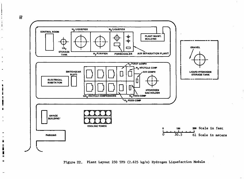
% LIQUEFIER CONTROL ROOM
N~LIOUEFIER
PLANT MAINT. BUI LDING
STORAGE TANK Hz PURIFIER FORECOOLER AIR SEPARATION PLANT
f , H2 PURlF COMPR 7 SWITCHGEAR
ELECTRICAL SUBSTATION
AIR COMPR
GAS HOLDER RECYCLE COMPRESSORS \ Np FEED COMP
OFFICE BUILDING'
PARKING I
Y"""
GRAVEL
LIQUID HYOROGEN STORhGE TANK
COOLING TOWER 0 100 200 Scale In feet Llrrlllll 0 30.5 61 Scale i n meters
Figure 22. Plant Layout 250 TPD (2.625 kg/s) Hydrogen Liquefaction Module

refrigeration content of the cold gas, assumed to amount to 8.424/kg (3.82$/lb) at 3$/kW, adds another $4.8 million annually which is equivalent to a present value of $20.1 million. An investment of up to $107 million can therefore be justifiably expended in the recovery of this cold hydrogen gas. Because recovery of the cold GH2 is so cost effective the cost analysis pre- sented in Section 5.1.2.3 is based on the assumption that all gaseous hydrogen bailed-off in ground operations at the airport is recovered and reliquefied.
4.4.7 Utilities. - Utilities for servicing the liquefaction complex when operating at 8.92 kg/s (850 tons/day) capacity are listed in Table XX. For other production rates , proportionality between utility consumption and pro- duction rate is a reasonable assumption.
Utility requirements are based on the assumption of successful completion of the development program cited in Ref. 7 and would be representative of technology in the year 2000. The development program includes improvement in compressor and expander efficiency, partial ortho-para conversion to 60 percent para), leakage reduction recovery of hydrogen from purifier tail gas.
Electricity is the major utility required and amounts to 331 800 kW. This translates to a unit power consumption of 10.33 kWh/kg (4.68 kWh/lb) of liquid hydrogen produced.
4.4.8 Costs. - Investment and operating costs and cost assumptions for the liquefaction/storage complex are presented in Tables XXI, XXII, and XXIII respectively. These data permit the unit cost for the LH2 to be determined as subsequently described in Section 5.1.
4.4.9 Personnel requirements. - Total manpower requirements for operating and maintaining the liquefaction/storage facility total 103 persons. This breaks down into four operating crews of 13 men each plus four maintenance crews of 7 men each. One foreman will also be required for each of the four shifts. This totals 84 persons or 2 1 persons per shift. In addition, ten office personnel, two foremen supervisors, a quality control analyst, two instrument technicians, two plant engineers, a plant superintendent and an assistant are required. This personnel complement is that required for operation of the liquefaction facility and does not include personnel required for aircraft fueling operations.
4.5 Task 7: Airport Fuel Distribution System
The object of this task was to identify feasible equipment and procedures for the LH2 distribution and fueling system. Such identification is con- sidered elemental to the study in that it will provide a basis for assessment of the problems and requirements of handling LH?-fueled aircraft at a desig- nated airport (SFO.) which, of course, is the primary objective of this study.
The LH2 fueling system is viewed as consisting of the aircraft fuel system, the groqnd distribution system (between storage and hydrant) , and the fueling equipment/procedures that provide the necessary interface between the

TABLE XX. UTILITY SUMMARY: HYDROGEN LIQUEFACTION/S'I'ORAGE COMPLEX, SAN FRANCISCO INTERNATIONAL AIRPORT
For 8.925 kg/s (850 tons/day)
E l e c t r i c a l Power - kW Production -
Hydrogen compressors Nitrogen recycle compressors Fbrecooler A i r compressor, N2 p l an t P u r i f i e r h e a t pump compressor Hydrogen feed/booster compressor Nitrogen feed compressor Hydrogen drier Pumps
176 720 73 010 9 220 4 440 9 310
1 5 680 7 440 2 310
575
Subto t a l
Hydrogen tu rb ine r e tu rn
Net Subtotal
Product ion Auxil iar ies
Cooling tower and water supply P lan t a i r compressor and drier Purge blower and thaw heater Miscellaneous
Sub t o tal
Process Contingency ( 5 % )
Subtotal
Plant Auxiliaries
Road and ex te r io r l i gh t ing Bui ld ing l igh t ing , hea t ing , a i r conditioning Cranes
298 705
24 605
1 5 770
330 300
300 7 50 250
1 300
84

TABLE XX. - Concluded
%tal Brought Forward
Fueling Pumps
331 609
200
Water - %tal , E l e c t r i c a l Power 331 800
- Cooling water makeup - m /s (gpm) Potable water - m3/s (gal /day)
3
Chemicals
Sulf 'ur ic acid for water treatment - kg/hr ( l b / h r ) 504 (1 110) Desiccants and adsorbents - kg/hr ( l b / h r ) 63 000 (139 0 0 0 )
Heating Fuel
For annual plant thaw kJ (Btu) 7.17 x l o 8 ( 6 . 8 x 10 ) 8

TABLE XXI. CAPITAL INVESrmENT: HYDROGEN LIQUEFACTION/STORAGE COMPLEX, SAN FRANCISCO INTERNATIONAL AIRPORT
10.5 kg/s (1000 tons/day)
Total plant investment
Interest dur ing cons t ruc t ion (1)
Sta r tup cos t s
Working c a p i t a l ( 2 )
$239 000 000
53 800 ooo
6 570 ooo
9 250 000
Total capi ta l requirement $308 620 000
(1) A t 1 2 pe rcen t i n t e re s t r a t e on t o t a l p l an t i nves tmen t fo r 1.875 years .
( 2 ) Sum of (1) materials and supplies a t 0.9 percent of t o t a l p l a n t investment plus ( 2 ) n e t receivables on product hydrogen a t 1/24 of annual production a t 80.82 $/kg (36.66 $/lb).
86

TABLE X X I I . ANNUAL OPERATING COST: HYDROGEN LIQUEFACTION/STORAGE.
(Base Case) COMPLEX, SAN FRANCISCO INTERNATIONAL AIRPORT
Raw Materials
Feedstock ( GH2 a t $0.1645/1b)
Chemicals
S u l f ” i c a c i d Desiccants and adsorbents
U t i l i t i e s
E l e c t r i c i t y 248 380 kW (a t $0.02/kWh) Cooling water makeup Potable water
Labor
Operating Labor Supervision
Administration and Overhead
Supplies
Operating Maintenance
Taxes and Insurance
$ 76 415 000
243 000 93 000
43 516 ooo 662 ooo
4 500
1 092 ooo 250 560
919 940
327 600 3 585 000
6 453 000
Total Annual Operating Cost $133 561 600
I 1111 I I1 I I1 111 11111111 I I I.= ,1111 .

TABLE X X I I I . COST ASSUMPTIONS : HYDROGEN LIQUEFACTION/STORAGE COMPLEX, SAN FRANCISCO INTERNATIONAL AIRPORT
2. Land assumed a v a i l a b l e a t no cos t .
3 . Cost o f l andf i l l inc luded .
4. Costs presented for mid-1975 d o l l a r s .
5. Average opera t ing capac i ty o f p lan t = 6.681 kg/s (636.3 T P D ) .
6. 350 operating days per year.
7. E l e c t r i c i t y c o s t s $0.02 per kwh.
8. Cooling water makeup cos t s $0.07925/m3 ($0.30/1000 g a l ) .
9.
10.
11.
12.
1 3 *
14.
1 5
16.
17
18.
19
20.
21.
Potable water makeup cos t s $0.13209/m3 ($0.50/1000 g a l ) .
S u l f l r i c a c i d c o s t s $0.05512/kg ($50/ ton) .
H2 feedstock costs $0.3627/kg (16.454/1b) of liquid hydrogen produced.
Opera t ing l abo r r a t e i s $6.50/hr.
Supervisory labor rates vary from $15 750 t o $33 000 per year .
Office personnel labor rate averages $5.50/hr.
Overhead c o s t s a t 60% of labor plus supervis ion.
Operat ing suppl ies are 30% of opera t ing labor .
Maintenance supplies are 1.5% of investment.
Taxes and insurance are 2.7% of investment.
Para content of m2 i n s t o r a g e = 97%+.
Para content of LH for operat ions = 60%.
1985 - 2000 l iquefact ion technology.
.. .
2
88

two component systems. The LH2 a i r c r a f t h e 1 system i s described in Reference 2. The pos tu la ted fue l ing procedure for SF0 i s br ie f ly descr ibed in Sec t ion 4.2.6 of the p resent repor t .
With an e s t a b l i s h e d a i r c r a f t fie1 system and a feasible fuel ing pro- cedure providing the primary ingredients to system formulation, a feasible ground d is t r ibu t ion concept i s ident i f ied th rough fur ther cons idera t ion of the following :
0 Vent gas d i spos i t ion
0 Transfer methods
0 Defueling considerations
0 Reliability/availability
0 Instrumentation
0 System arrangement
0 Hazards analysis
It should be noted that the ground dis t r ibut ion system resul t ing from t h i s a n a l y s i s is not on ly feas ib le , bu t , in contex t wi th the s tudy ob jec t ives , i s both reasonable and appropriate for assessing the implicat ions of handl ing U p f u e l e d a i r c r a f t at SFO. That is no t t o s ay t ha t t h i s concep t i s t h e optimum solu t ion (as might be derived by de ta i led des ign ana lys i s ) or t h a t it would be equally appropriate at another a i rpor t loca t ion . A s pointed out in Task 4, another a i rpor t s i t e might very wel l require an ent i re ly different approach t o t h e f u e l i n g o p e r a t i o n and at tendant dis t r ibut ion system.
4.5.1 Fueling system description. - Development of a f e a s i b l e LH2 d i s t r i - bution and fueling system concept is, of course, largely dependent upon t h e locat ion and nature of the a i rcraf t f 'uel ing operat ion. The evaluation of a l t e rna t ive fue l ing p rocedures d i scussed i n Task 4 concluded with the select ion of a gate fuel ing system as t h e most appropr ia te for SFO. The dis t r ibut ion concept i s , therefore , p red ica ted on a fuel ing operat ion per- formed a t the t e rmina l ga t e by a fueler vehicle equipped to provide a l l necessary interfaces between a hydrant point of supply and the aircraft fuel system.
Each of the 19 gate f 'uel ing s ta t ions w i l l consis t of a hydrant p i t ( see Figure 23) containing interface connect points for LH2 supply and hydrogen vent gas col lect ion. The LH2 hydrant can be connected to e i ther of two vacuum jacke ted d i s t r ibu t ion l oops i n which subcooled LH2 i s c i r cu la t ed from t h e s t o r a g e f a c i l i t y a t appropriate operat ing pressures . The vent hydrant will be connected t o a vent col lect ion header and routed to the s torage and l i q u e f a c t i o n f a c i l i t y . As shown i n t h e f i g u r e , t h e h y d r a n t p i t i s equipped with a riser from each of t h e LH2 supply loops. The risers are connected
1 . . .. . .. . . "" .. - - ". -. .

7-BOILOFF R E C O V E R Y ', V A L V E ,
PROTECTIVE COVER
H Y D R A N T P UELER / - - E X T R A H E A V Y H O S E CONICTIONS 7 DUTY G R A T I N G

through service isolation valves to a hydrant shutoff valve and an LH2 transfer disconnect device. The vent gas displaced from the aircraft tanks during refueling will be routed through the fueler vehicle to a vent dis- connect device. A vent shutoff valve and service isolation valve connect the disconnect device to the vent collection header. This equipment will be situated in a pit located in the apron below the tail of the aircraft.
The refueling operation will be carried out by a hydrant f’ueler vehicle equipped to provide the fluid and operational interfaces between a hydrant pit and the aircraft. A flow schematic of the hydrant fueling operation is illustrated in Figure 24.
Vacuum jacketed metal bellows flex hose connections will be made from the hydrant truck to the LH2 and vent connection devices in the pit. At the same time vacuum-jacketed flex hoses will be mated to the aircraft LH2 and vent connect points using a cherry picker to lift a man to the 10 m (33 ft ) height of the aircraft tail (see Figure 17). The hoses mated to the pit hydrants and to the aircraft are interconnected by vacuum jacketed piping complete with valves and instruments. The hydrant fueler truck wiil carry a vacuum pump, high pressure helium bottle and the necessary valves and controls to permit purification (the removal of all traces of air and moisture) of the flex hoses prior to the introduction of hydrogen.
Refer to Figure 23 for the following discussion of the fueling pro- cedures. The purification process consists of evacuating the two liquid flex hoses and the two vent flex hoses to a level of 6.9 kPa (1 psia) or less with the vacuum pump (exhausting to atmosphere) followed by pressurization of the lines to 344.8 kPa (50 psia) with helium. Repetition of this evacuation/ pressure cycle four times should reduce the air-moisture contamination to less than one part per million (ppm). The exact pressure levels and pro- cedures to be used will be verified experimentally. A system leak check will be performed on the last purification cycle with the pressure at 344.8 kPa (50 psia).
All valves involved in the fueling operation are controlled from a sequencer on the fueler vehicle by means of an instrumentation and control cable connected both to the aircraft and the hydrant pit. The vaives to be controlled are:
0 Aircraft
0 Fueler Vehicle
0 Hydrant pit
Vent selector valve Bleed valve Fueling control valve
Two LH2 hose isolation valves Two vent hose isolation valves Purification and inertion valves
LH2 hydrant valve Hydrant vent valve Inertion vent valve

Upon completion of the purification sequence, the hydrant vent valve a d fueler vent hose isolation valves are opened, the aircraft vent selector is set to the refueling position, and the bleed valve is opened. The f'ueler m2 hose isolation valves and the LH2 hydrant valve are then opened, allowing L H ~ to circulate through the system via the bleed valve, to chill down the fueler system. When liquid temperatures are sensed at the aircraft,'the bleed valve is closed, the fill valves are opened and tank filling commences. The tank level is monitored and when the level reaches the desired point and flow ceases, the fill valves are closed.
At the conclusion of the filling operation the LH2 hydrant valve is closed, the aircraft vent selector is set to the tail vent position, and the bleed valve is opened. The hydrant vent valve and the four fueler hose isolation valves are closed, trapping cold hydrogen between each set of valves. This permits the piping section of the f'ueler, which represents about two-thirds of the fluid system mass, to remain chilled for the next fueling operation. Only the flex hose sections will require inertion before they are disconnected. Any pressure rise of the hydrogen in the piping sections due to heat leak will be relieved by the pressure safety valves shown in Figure 24. It should be noted that additional pressure relief valves will be required throughout the system; these have been omitted for clarity of presentation.
The inerting process (removal of the residual hydrogen) will consist of pressurizing the two LH2 hoses and the two vent hoses with helium to 344.8 kPa (50 psia) and then venting them to the vent collection header via the inertion vent valve. This will vaporize any residual LH2 in the fill hoses. The hoses are then evacuated to 6.9 kPa (1 psia) with the vacuum pump, exhausting to the vent collection header. The line will again be pressurized to 344.8 kPa ( 5 0 psia) with helium and vented. This evacuation/pressure cycle will be repeated twice to reduce the hydrogen concentration to 10 000 parts per million (ppm). The flex hoses are disconnected and the procedure is completed.
4.5.2 Ground distribution and refueling system. - The distribution of LH2 throughout the terminal area to each of the 19 required gates presents some unique problems not encountered in previous systems associated with the space programs. The schedule and aircraft utilization constraints require that the LH2 fueling system chilldown time be kept to a minimum. Operational flexi- bility is required which will permit an aircraft to obtain fuel upon arrival at its assigned gate without extensive planning and scheduling or elaborate communications with the LH2 storage facility operator. Subcooled LH2 must be supplied to the aircraft to minimize fuel losses,due to flashing of the liquid after it is introduced into the tank. (This reduces the volumetric floV rate in the vent system, reducing aircraft vent system size and weight, and per- mitting higher fueling rates).
An LH2 distribution system concept has been developed which addresses these requirements. This concept is depicted schematically in Figures 25 and 26. The basic system is a circulating LH2 distribution loop which is fed

GH2 VENT COLLECTOR -"--- LH2 MAIN SUPPLY LOOP +-
LH2 SPARE SUPPLY LOOP
I I L"""A
(TYPICAL) HYDRAULIC PIT
INSTRUMENTAT AND CONTROL C
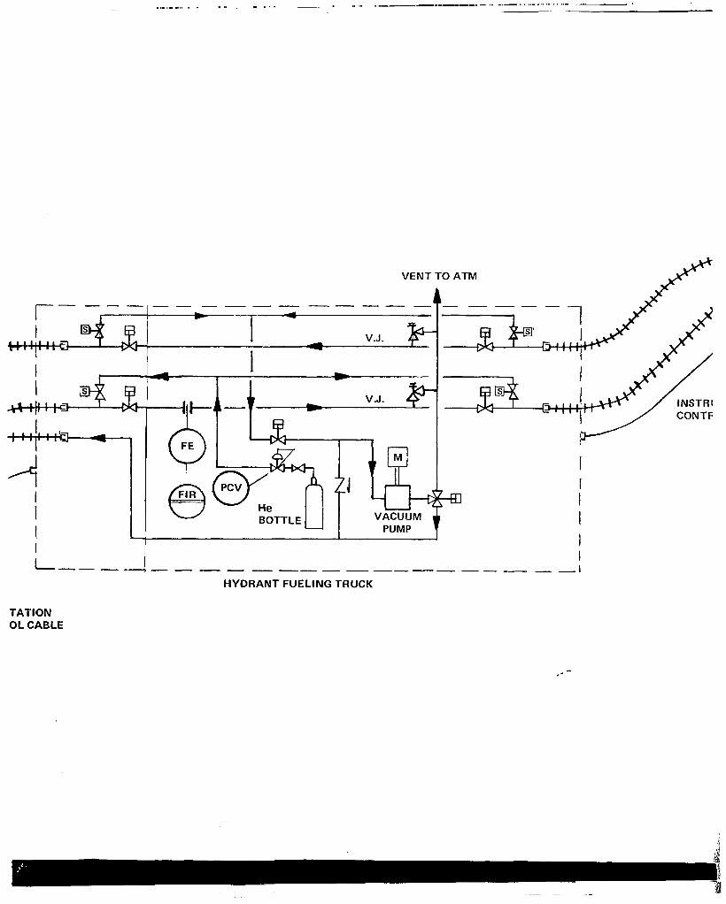
I
7-1 I L I I""
.,.,,.,CII . . . .. . . -~ . .... .""""" "._"...._."...."... - .... - ... . . I
- ' I
VENT
"_"""" 1 "T -
I V.J.
I I I 1 I I """""_ "- "" 1
HYDRANT FUELING TRUCK
TATION OL CABLE
r - e

TO TAIL VENT
VENT SELECTOR
" " . . . . . . -
J~ENTA I IWN AND IL CABLE
-" +%"
""_
SYMBOLS
PROCESS LINE
FLEXIBLE HOSE
SERVICE ISOLATION VALVE
SOLEfNOlD OPERATED VALVE
HYDRAULIC OR PNEUMATIC PISTON OPEPQTED CONTROL VALVE
HYDKAULIC OR PNEUMATIC PISTON THREE-WAY OPERATED CONTROL VALVE
THREE-WAY VALVE
CHECk VALVE
BACK PRESSURE REGULATOR SELF CONTAINED
DIAPHRAGM OPERATED VALVE
FILTER
ELECTRIC SIGNAL
t
REAR LH2 FUEL TANK
0 INTERLOCK FLOW INDICATING CONTROLLER
@ FLOW INDICATING RECORDER
6 PRESSURE CONTROL VALVE
@ TEMPERATURE ELEMENT
PRESSURE ELEMENT
FLOW ELEMENT
MOTOR DRIVEN CENTRIFUGAL PUMP a, MOTOR DRIVEN RECIPROCATING COMPRESSOR
E)=O MOTOR DRIVEN-RECIPROCATING VACUUM PUMP
COUPLING
;4" PRESSURE RELIEF VALVE
Figure 24. H y d r a n t F u e l i n g S c h e m a t i c
93

with -252.8Oc (-423OF) sa tu ra t ed LH2 from a s torage dewar. The l i qu id l oop is routed past each of t h e 19 hydrant p i t s (one for each ga te ) , then re turned to the s torage sys tem (F igure 27) .
LH2 i s c i rcu la ted th rough the loop a t a flow .rate s u f f i c i e n t t o l i m i t the temperature rise due t o h e a t l e a k t o &.O°C (1.8OF), t he s a tu ra t ed equivalent of 137.9 kPa (20 psia) , -251.7 C (-421.2OF) , at t h e last hydrant on the loop. The c i r c u l a t i n g l i q u i d i s then r e tu rned t o t he s to rage area w h e r e ' i t i s in t roduced in to a vented storage dewar t o b e b o i l e d back t o saturat ion condi t ions at 103.4 kPa (15 p s i a ) . It should be noted that no add i t iona l LH2 lpss penal ty i s incurred by t h i s o p e r a t i n g method because the frequency of system operation i s such t h a t t h e i n n e r l i n e o f t h e vacuum i n s u l a t e d p i p q w i l l n o t warm up s i g n i f i c a n t l y above l iquid temperatures. Thus, t he hea t l eak i n to t he d i s t r ibu t ion sys t em w i l l remain e s s e n t i a l l y constant no matter what t he l i qu id f l ow rate. The primary advantages of this approach are the vir tual e l iminat ion of chi l ldown time and t h e immediate avai labi l i ty of subcooled LH2 a t each hydrant station, with the additional benefit of reduced LH2 losses normally incurred by droplet carryover during chilldown of the ground distribution system.
System o p e r a t i n g f l e x i b i l i t y i s assured by a d i s t r ibu t ion p re s su re control system which provides constant LH2 p r e s s u r e t o t h e hydrants and t h e fue l e r veh ic l e . The LH2 loop w i l l operate a t 241.3 kPa (35 p s i a ) , allowing a 48.3 kPad ( 7 p s i d ) loss through the hydrant valve and the fueler vehicle to ensure a 193.1 kPa (28 p s i a ) a i r c r a f t i n t e r f a c e p r e s s u r e when fue l ing at the design ra te of 11 354 l / m (3000 gpm) to t he des ign a i r c ra f t t ank p re s su re of 144.8 kPa ( 2 1 p s i a ) . The pressure in the loop i s con t ro l l ed by a back pressure regula tor loca ted a t the s to rage area end of t h e LH2 r e t u r n l i n e . This valve i s cont ro l led by a pressure sensor located a t t h e last hydrant on the loop . A s t he back pressure regulator reaches the extremes of i t s ava i l - able control range, transfer pumps a r e e i t h e r brought on l i n e or dropped o f f l i n e , as requi red to main ta in the cons tan t LH2 supply pressure. During idle per iods , one t r a n s f e r pump remains on l i n e t o i n s u r e the ava i l ab i l i t y o f
development o f t he t r ans fe r method concept i s discussed in Sect ion 4.5.3. ubcooled l i q u i d and to maintain constant supply pressure. The r a t i o n a l e f o r
The operation of the hydrant fueler vehicle (see Section 4.5.1) i s r e l a t i v e l y immune t o problems of schedule and communication cons t r a in t s between the actual fuel ing operat ion and the operat ion of the central .?+orage and transfer system.
4.5.3 LH2 t r a n s f e r method. - Both pressur ized s torage dewar t r a n s f e r and pump t r a n s f e r were considered as methods of moving f u e l from s t o r a g e t o a i r c r a f t . The pressur ized s torage dewar t r a n s f e r method offers the obvious advantage of system simplicity (in that the problems associated with mechani- c a l pumps are e l iminated) and a degree o f f lex ib i l i ty ( in f low rate vs demand), not a v a i l a b l e i n a pump fed system.
There are, however, some d isadvantages to a pressure fed system. The most s ignif icant of these includes losses through heat transfer from t h e pressurant gas t o t h e l i q u i d and t h e need t o vent the s torage t ank back to

A pump fed system also has drawbacks, principally the increased system complexi ty wi th the a t tendant degrada t ion in re l iab i l i ty . In addi t ion , the required demand f l e x i b i l i t y i s somewhat more d i f f i c u l t t o a c h i e v e . It was concluded, however, tha t the lower losses assoc ia ted wi th pump t r a n s f e r were su f f i c i en t ly a t t r ac t ive t ha t sys t em would be adopted for th i s ana lys i s .
The proposed LH2 dis t r ibut ion system consis ts of a pump fed system operating on an uninterrupted basis requir ing only one tank pressurizat ion cycle as desc r ibed i n t he Task 3 na r ra t ive . The proposed system addresses the major drawbacks of a pump fed sys tem, those o f re l iab i l i ty and demand f l e x i b i l i t y . To provide the necessary re l iab i l i ty , mul t ip le pumps a r e contemplated. Each of these pumps i s r a t e d a t 11 354 l / m (3000 am) and has t he capac i ty t o fue l one a i r c r a f t a t the des ign f low ra te . Demand f l e x i b i l i t y i s achieved by sequencing one or more pumps on l i n e on t h e basis of d i s t r ibu t ion l oop back pressure control, as described in Section 4.5.2. These pumps are c lose-coupled to the s torage dewars to minimize heat leak i n t o t h e pump suct ion piping, thus avoiding pump start up problems caused by two-phase f l u i d and the a t tendant l ack of net posi t ive suct ion head (NPSH). The c1os.e coupled configuration limits f l e x i b i l i t y t o t h e e x t e n t t h a t a pump can be u t i l i z e d o n l y t o withdraw LH2 from t h e dewar t o which it is mated. I n normal conditions, a l l fuel ing operat ions are suppl ied f’rom one dewar. Thus, all f ive s to rage dewars are equipped with pumps so t h a t a l l may provide the d i s t r i b u t i o n . A t the design peak four a i rcraf t may require fuel simultaneously, thus, four 11 354 l / m (3000 gpm) r a t ed pumps are required per storage dewar. This provides 100% pump capacity redundancy during normal operation (two a i r c r a f t f u e l i n g ) ; d u r i n g peak periods a pump outage w i i l r equ i r e t ha t one of the reserve dewars be brought on l i n e t o p r o v i d e s u f f i c i e n t pump capaci ty .
The amount of LH2 t o be c i rcu la ted th rough the d i s t r ibu t ion loop dur ing id le per iods to main ta in the requi red l iqu id qua l i ty has been determined t o be on the order of 3028 l / m (800 gprn). Separate pumps r a t ed at 3028 l / m (800 g p m ) each could be provided for each storage dewar t o supply the minimum c i r cu la t ion f l ow ( t en add i t iona l pumps). However, the heat leak of the piping associated with these pumps and the complexity of additional valves, controls and instrumentation does not appear advantageous when com- pared t o providing the c i rculat ion f low with one of t h e main t r a n s f e r pumps at 11 354 l / m (3000 gprn). The only penalty incurred with this approach i s a s l i g h t i n c r e a s e i n LH2 los ses due to excess ive pump work. However, as a result o f c i r cu la t ing at the h igher rate, t h e maximum time t h a t a supply dewar will remain pressurized, before the l iquid i s depleted by c i r c u l a t i o n t o t h e r e t u r n dewar, i s approximately 5-1/2 hours. The bulk temperature r ise o f t he l i qu id i n t he supp ly dewar should not exceed the operating limits dur ing th i s per iod , permi t t ing un in te r rupted opera t ion of a dewar from fill

' COLD GH2
PRESSURANT SUPPLY
FROM NO. 1 LH2
LIQUEFACTION UNIT
FROM NO. 2 LH2
LIQUEFACTION UNIT
FROM NO. 3 LH2
LIQUEFACTION UNIT
FROM NO. 4 LH2
LIQUEFACTION UNIT
a
L IHELlUM RECOVERED \ FROM H2 VENT GAS L - K
RECYC HELIUM COMl

NO. 1 OF 5 LH2 STORAGE DEWAR
1,000,000 + GAL (3785 + m3)
(25.4 cm) 10" V.J. LH2 SUPPLY LOOP (MAIN LOOP) - I
IO" V.J. (25.4 cm)
E 3ESSOR
N
He R-ECYCLE L -
.- LH2 TRANSFER PUMPS
3 , 0 0 0 ~ ~ ~ (or 11.35 m3/min) (TYPICAL OF 4)
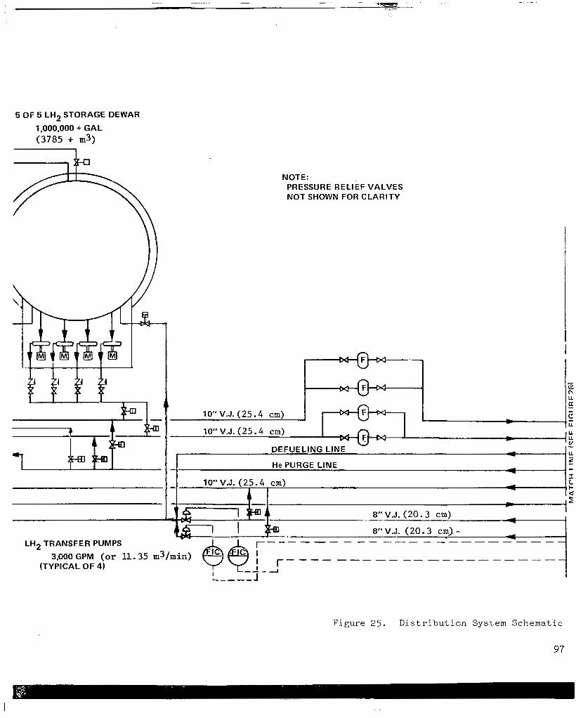
5 OF 5 LH2 STORAGE DEWAR
1,000,000 + GAL (3785 + m3)
NOTE: PRESSURE RELIEF VALVES NOT SHOWN FOR CLARITY
I
F i g u r e 2 5 . D i s t r i b u t i o n S y s t e m S c h e m a t i c
97
I +
- U c\ U
l a 10" V.J. (25 .4 cm)
10" V.J. (25 .4 cm)
- - c L rr - U
U - U U
DEFUELING LINE
He PURGE LINE
~~ ~
c
1 - 2 - - A - -
10" V.J. (25 .4 cm) I c - I- d - ~~
2 L L -
8" V.J. (20 .3 cm)
8" V.J. (20.3 cm). - LH2 TRANSFER PUMPS
(TYPICAL OF 4)
"""" - """ -------
3,000 GPM (or 11.35 m3/min) """"""" -------

. . \ I
Figure 27. Distribution Loop Corlcept Plan
101

to empty without venting and repressurization and avoiding the associated losses.. Accordingly, circulation of LH2 through the distribution system during periods when no aircraft are refueling will be provided by one of the 11 354 l/m (3000 gpm) pumps.
4.5.4 Vent gas disposition. - The operation of a liquid hydrogen system produces hydrogen gas from boil-off of stored liquid, and from vaporization of liquid used to chill down piping, tanks and equipment. Volumes of the gas are a lso displaced from tanks during the filling operation. This hydrogen gas haE been traditionally disposed of by burning in air through a flare stack or bubble pond. However, the unique aspects of the airport hydrogen production, distribution and fueling systems make it advantageous to recover and recycle this hydrogen gas. The advantages include: 1) conservation of the refrigeration energy contained in the cold vent gas stream; 2) recovery of the hydrogen molecule, thus, reducing the GH2 feed rate by approximately 12 to 15 percent; and 3) eliminating the need for an extensive hydrogen gas burn-off system with its attendant siting problems.
The aspect of the airport system which encourages the recovery approach is the on-site location of the li uefaction plant. This allows the cold vent gas at approximately -24OoC (-400 F) , to be returned and inserted at an appropriate point in the liquefaction process that can effectively make use of the refrigeration energy in the cold ga,s stream. This requires that an efficient insulation be used on the vent collection header. The proposed concept uses vacuum jacketed pipe for the vent gas system.
8
The reintroduction of the recovered vent gas into the liquefier does present a problem of gas purity. The cold gas stream must not contain condensable gases such as N2, 02, C02 o r water vapor; it must consist of only H2, with limited quantities of He permitted. To this end, all sources of these gases have been excluded from the concept and the helium/vacuum purification-inertion system previously described has been incorporated in the hydrant fueler truck. This permits air and moisture to be withdrawn from the fueling hoses and vented to the atmosphere during the prefueling purification cycles, and gaseous hydrogen to be purged from the hoses to the vent collection header by helium pressure/vacuum during the post-fueling inertion cycles. The resulting small quantities of helium contained in the otherwise pure hydrogen gas stream is separated from the hydrogen in the natural course of the liquefaction process in that it does not liquefy, and may be drawn off and compressed for reuse.
Matching the hydrogen gas recovery rate with the liquefaction process demand rate will require surge capacity in the form of an insulated or vacuum jacketed vessel. The sizing of this vessel and methods of matching recovery and demand rates will require study beyond the scope of this investigation; however, the requirement for a GH2 holding dewar is indicated on Figure 21.
I

In addi t ion to the vent gas recovered dur ing rou t ine fue l ing opera t ions , other sources of recoverable hydrogen gas include:
0 The gas evolved by the boil-down o f l i q u i d i n t h e r e t u r n dewar (which conta ins the hea t added by t r a n s f e r pump work and d is t r ibu t ion sys tem heat leak) .
0 The vent down of the supply dewar following dispensing of i t s contents.
0 The boil-o'ff from the three reserve storage dewars.
0 The tank. boil-off from fue led a i rc raf t parked for ex tended per iods of time ( inc lud ing a i r c ra f t i n ma in tenance f ac i l i t i e s equ ipped w i th vent col lect ion systems) .
The recoverable wdrogen gas from vaporized chil ldown l iquid i s l i m i t e d t o t h a t evolved during chilldown of a warm d i s t r i b u t i o n loop and chilldown of the hydrant fueler hoses during each refueling operation.
During the fue l ing opera t ion the ullage gas displaced from t h e a i r c r a f t tanks i s routed from the t ank vent se lec tor va lve to the vent co l lec t ion header via the hydrant fueler vehicle .
Recovery of tank boi l -off from a i r c r a f t t h a t a r e t o be parked for extended periods (such as overnight parking at a g a t e ) w i l l be accomplished by a vacuum-jacketed f l e x hose connected between the hydrant p i t ( s e e Figure 22) and the a i r c r a f t . The procedure w i l l require use of the hydrant fue l e r veh ic l e t o pe r fo rm pu r i f i ca t ion s t eps and f o r making t h e f l e x hose connection to t he a i r c ra f t ven t connec t po in t . The insulated f lex hose should be protected from p o t e n t i a l damage by miscellaneous ground service equipment during the storage period while the hydrant fueler vehicle i s not there, perhaps by bar r icade pos ts tha t rrpop-up" from the apron . Pr ior to a i rc raf t depar ture , the hydrant fue le r vehic le would return, the vent hose would be disconnected, and t r i p f u e l i n g as described i n sect ion 4 .5 .1 would be performed.
4.5.5 Defueling/refueling "~ " f D r a i rcraf t maintenance. - Defueling of the LH2 a i r c r a f t will be necessary for extended out-of-service periods for major maintenance or when fue l t ank r epa i r i s required. Defuel ing of the a i rcraf t tanks w i l l be accomplished through the defueling valve by operat ing the a i r c r a f t tank-mounted boost pumps, wi th the fue l be ing re turned to s torage by one of the following methods:
0 A t a special area designated for defuel ing/refuel ing extended ou t -o f - se rv ice a i r c ra f t ( s epa ra t e r e tu rn l i ne ) .
0 A t the se rv ice re fue l ing s -ca t ion . (ga te ) , pumping t h e l i q u i d back i n t o t h e main d is t r ibu t ion sys tem.

0 Use of t r u c k - t r a i i e r t r a n s p o r t s .
0 Use of demountable tanks (external tank design).
The u s e o f t r u c k - t r a i l e r t r a n s p o r t s f o r r e t u r n i n g f u e l t o s t o r a g e seems imprac t ica l un less re la t ive ly small quant i t ies o f LH2 are involved, and unless there i s a requirement for a mobile source of LH2. This procedure would incu r s ign i f i can t on-and-off loading t ransfer losses , and , more importantly, would r equ i r e cos t ly spec ia l equipment t h a t would be u t i l i z e d only infrequent ly . A s a r e s u l t , whether defueling i s performed a t the ga t e o r at some o ther remote a i rpor t loca t ion , use o f t ruck- t ra i le r t ranspor t s i s not economically a t t r ac t ive ove r t he i nhe ren t ly sho r t d i s t ances t ha t fue l would have t o be t r ans fe r r ed a t SFO.
Consideration of a defueling procedure uti l izing demountable tanks i s , of course, predicated on the ex te rna l t ank a i r c ra f t des ign . The concept of removable tanks has advantages with respect to maintenance considerations and a unique potent ia l for refuel ing and defuel ing. A s pointed out in Task 4, however, s i t e c o n s t r a i n t s at SF0 m i l i t a t e a g a i n s t any of t h e ground concepts b u i l t around remote fac i l i t i es . In addi t ion , opera t iona l d i sadvantages weigh aga ins t the Externa l Tank design.
The question remaining, then, i s whether a i r c r a f t d e f u e l i n g might bes t be performed at t h e m i s s i o n r e f u e l i n g s t a t i o n ( i n t h i s c a s e t h e t e r m i n a l g a t e ) o r a t some o ther des igna ted a i rpor t loca t ion . This ques t ion i s answered primarily through consideration of "defuel ing time". Although the t ime r equ i r ed t o de fue l an a i r c r a f t w i l l be dependent upon the capaci ty of the a i r c r a f t pumps and f u e l l i n e s , it i s probable tha t defue l ing (defue l and i n e r t ) w i l l r e q u i r e f o u r t o s i x h o u r s f o r a f u l l t a n k . A s a r e s u l t , it was concluded tha t a i rc raf t defue l ing , though occur r ing on ly in f requent ly , should be separated from t e rmina l ga t e ac t iv i ty r e l a t ed t o i n - se rv ice air- craft . This conclusion i s reinforced by considerat ion of operat ional safety, e f f ic iency of vehic le and a i rc raf t g round t ra f f ic , and the a s soc ia t ed impact on terminal operat ions.
The defueling operation can most appropriately be accommodated at t h e same s i t e d e s i g n a t e d f o r f u e l i n g a i r c r a f t t h a t a r e b e i n g r e t u r n e d t o s e r v i c e following maintenance. A basic assumption of the refueling procedure adopted i n Task 4 was t h a t a i r c r a f t would not remain a t the gate for extended per iods and t h a t o n l y t r i p f u e l i n g o f a i r c r a f t w i t h c o l d t a n k s would be performed at the ga t e . Fu r the r , it has been postulated that chil ldown and fueling of a i r c r a f t coming from maintenance or long-term remote parking w i l l be per- formed at a s p e c i a l f u e l i n g area, preferab ly in c lose p roximi ty to the LH2 s t o r a g e f a c i l i t y .
A s p e c i a l f u e l i n g area i s envis ioned ad jacent to the LH2 s torage f ac i l i t y , p rov id ing s eve ra l de fue l ing or refuel ing posi t ions. This concept of a spec ia l fac i l i ty for re fue l ing /defue l ing ex tended ou t -of -serv ice a i rc raf t i s a t t r ac t ive bo th from the s tandpoin t of economics and a i rpo r t ope ra t ions ,

A s d i scussed i n Task 8, a l l possible a i rcraf t maintenance w i l l be per- formed w i t h t h e a i r c r a f t i n the fue led condi t ion . However, those funct ions requi r ing work d i r e c t l y on t h e f u e l t a n k s w i l l necess i ta te defue l ing of the a i r c r a f t and subsequent refueling. The cryogenic nature of the fuel requires that unique procedures be performed pr ior to ini t ia t ion of the tank mainte- nance and again prior t o r e t u r n i n g t h e a i r c r a f t t o s e r v i c e . These operations consis t of iner t ing of the tank ( the removal of hydrogen gas t o a con- cent ra t ion of 10 000 ppm o r less) , and controlled warmup o f t he t ank t o a temperature above dew point to prevent moisture condensat ion.
Following the completion of tank maintenance, the tanks must be purified (removal of a l l t r aces o f air and moisture t o a contamination l e v e l of 1 t o 1 0 ppm) p r io r t o ch i l l down and refueling.
These func t ions (defue l ing , iner t ing , warmup, purif icat ion, chi l ldown, and r e fue l ing ) r equ i r e su f f i c i en t spec ia l i zed equipment t o warrant considera- t ion o f a cen t r a l i zed f ac i l i t y capab le o f s e rv ing a l l c a r r i e r s . T h i s f a c z l i t y might be located adjacent to the l iquefact ion and s torage complex t o minimize piping and operat ional interface problems.
With t h e a i r c r a f t t a i l s i t u a t e d a t the defue l / re fue l s tand , a f lex hose is mated to t he fue l connec t po in t at the t a i l cone of the a i rcraf t . The interconnect hose i s p u r i f i e d and the conten ts o f the tank a re pumped t o the LH2 re turn s torage dewar v i a t h e LH2 re turn header .
The i n i t i a l phase o f a i rc raf t fue l t ank warmup must be performed using heated hydrogen gas as the hea t source f lu id . The warm hydrogen gas must be used u n t i l t h e t a n k w a l l temperature i s brought above the nitrogen conden- sation temperature of -195.5OC (-3200F). A t t h a t po in t the heat source f l u i d may be switched to d ry n i t rogen gas .
The most effect ive procedure to expedi te tank warmup i s the introduct ion of the heated gas 93.3OC t o 148.goC (200°F t o 300OF) in to t he t ank with the vent closed and subsequent pressurization of the tank to i t s maximum sea leve l p ressure . This pressure i s he ld fo r two to f i ve minu te s t o pe rmi t hea t t r a n s f e r from the gas t o t he t ank . The tank is then vented to the GH2 recovery header or to the a tmospher ic f la re s tack dur ing and a f t e r t he swi t ch to hea ted n i t rogen . This procedure is r epea ted un t i l t he t ank w a l l is above t h e dew point temperature for ambient atmosphere, a t which point enough ni t rogen has been cycled through the tank to effect tank iner t ion. The aircraf t , having been defueled, warmed, and iner ted, i s then moved t o t h e maintenance f ac i l i t y fo r t he r equ i r ed ma in tenance .
P r io r t o t he i n t roduc t ion o f hydrogen i n t o t h e tanks of an a i r c r a f t re turning from maintenance, a i r o r oxygen must be removed from the t ank . If t h e a i r c r a f t i s t o be refueled with l iquid hydrogen, then a l l t r a c e s of condensable gases such as nitrogen, carbon dioxide, and water vapor must a l s o be removed. If the maintenance act ivi ty has introduced l i t t l e o r no air i n t o the t anks , t hen pu r i f i ca t ion o f t he t anks may be accomplished by pressure/ vent cycling the tank with hydrogen gas t o reduce the condensable contami- n a t i o n l e v e l t o between one and t en pa r t s pe r mi l l i on . If air has been

in t roduced in to the t ank , then a nitrogen pressure/vent cycle i s required p r i o r t o t h e hydrogen gas cycle t o reduce the a i r contamination level t o 1 0 000 par ts per mil l ion. This procedure is then followed by the co ld hydrogen gas purification cycling as described above.
Fueling an empty tank must be performed at low rates t o avoid over- p re s su r i z ing t he a i r c ra f t t ank . As t h e l i q u i d i s introduced, it f l a s h e s t o vapor and the t ank vent t ends to choke . To avoid overpressurizing the tank, the re fue l ing s tand i s equipped with a pressure cont ro l valve which meters t h e l i q u i d f e d from the d i s t r ibu t ion sys t em in to t he a i r c ra f t t ank by sensing tank pressure. The vent gases evolved during refueling are co l l ec t ed i n t he GH2 recovery header. The procedures descr ibed above for a i rcraf t tank chi l l - down and fue l ing may take from two to twelve hours, dependent on tank mass, configuration and tank vent capacity.
4.5.6 System r e l i a b i l i t y and ava i l ab i l i t y . - It i s obv ious t ha t a i r l i ne operations are completely dependent upon the continuous supply of fuel from t h e LH2 product ion, s torage, d is t r ibut ion and fuel ing systems, and cannot t o l e r a t e a complete outage i n t h e a v a i l a b i l i t y o f LH2. It i s assumed t h a t contingency procedures can be postulated to permit continued LH2 del ivery i n the event of system fai lure . The following i s a summary of the major systems and typical contingency procedures for system or component f a i l u r e i n each of them:
0 Liquefact ion Plant . - The proposed plant, as descr ibed in the Task 6 narrative, consists of four totally independent production modules, any t h r e e of which can produce a l l but peak demand and any two of which can produce 80% of average demand. This redundancy should provide suf f ic ien t LH2 p r o d u c t a v a i l a b i l i t y t o meet most emergency shutdowns.
0 LH2 Storage. - The proposed LH2 s torage cons is t s o f f ive s torage dewars each of one million gallon capacity. Duringj a peak month, the average dai ly demand i s approximately 10 977 m (2 .9 mi l l ion gallons). Three of these dewars w i l l be maintained in a topped o f f cond i t ion t o p rov ide a minimum of 24 hol r reserve . A fourth dewar w i l l be on l ine feeding the d i s t r ibu t ion sys tem wi th the remaining dewar vented to accept LH2 production output and liquid re turned from the c i r cu la t ing d i s t r ibu t ion l oop . Under normal condi t ions , the two operating dewars (supply and return) will contain at l e a s t a million gallons between them, so t h a t a t o t a l reserve of 1762 m3 (4 mil l ion ga l lons ) may be assumed t o be ava i l ab le . All dewars w i l l be configured to serve as (1) reserve s torage , ( 2 ) LH2 supply, and (3 ) LH2 rece iver , thus , a l l of t h e required functions can be performed by any dewar and and one dewar can be out of service with no de t r imen ta l e f f ec t . When two or t h ree dewars are out of service, only the desired reserve capaci ty would be reduced.
106

0 LH2 Distribution. - The concept of' a single LJ-I2 distribution loop from the storage complex to the gate hydrant pits introduces significant system availability problems in the event of downtime. The loss of vacuum in any vacuum insulated pipe section would immediately reduce system operating efficiency, and the downtime of the entire fueling system required f o r the repair of such a problem would be intolerable. Thus, the suggested distribution concept incorporates redundant LH2 circulating distribution loops. Any storage tank is,capable of feeding either an in-service supply loop or the standby supply loop. Both loops are routed to each hydrant pit where service isolation valves permit the hydrant feed to be selected from either subsystem.
Each loop will nominally be capable of fueling two aircraft simultaneously at the design flow rate of 11 354 E/m (3000 gpm) each. Peak demand (summer months) requires capability to fuel four aircraft simultaneously, and both loops would be in service during these periods. True redundancy is not achieved with the dual loops, in that fueling capability is below design loads if' one loop malfunctions in the busy months. However, continuity of service can be maintained. In the event of a pipe section vacuum failure, a correction can be effected by removal and replacement of the defective pipe section with a certified spare section. Assuming that cryogenic system maintenance capability is available at the airport site (see Section' 5 .l. 3.1) , it is estimated that from 8-12 hours would be required to replace the defective pipe section and return the loop to service. Repair of the defective section would be performed in a central facility.
4.5.7 Instrumentation. - Several operating parameters of the fueling process must be monitored to assure proper system operation. These include:
0 Storage dewar pressure
0 Distribution loop LH2 temperatures
0 Fueler hose pressure/vacuum
0 vacuum insulation pressure
0 Storage dewar quantity
The quantity of LH2 dispensed to a given aircraft must also be accurately metered. The following brief discussion describes typical instrumentation equipment for measurement of these parameters based on the current state of the art.
Dewar Pressure. - A strain gage type of absolute pressure transducer with a nominal 5 volt dc output could be used for this application. Digital display readouts would be standard.

0
0
0
0
0
As
Distribution Loop Temperatures. - Platinum element resistance temperature bulbs could be incorporated at several points throughout the system. Again, digital readouts would be used.
Fueler Hose Pressure/Vacuum. - A strain gage would be used for this application to monitor the pressure levels during the purification and inertion cycles.
Vacuum Insulation Pressure. - A thermocouple type gage would be used to indicate the low vacuum existing in the insulation jacket.
Storage Dewar Quantity. - A sensitive differential pressure cell will provide sufficient accuracy to determine the quantity of LH2 in storage.
LH? Delivery Quantity. - The quantity of liquid fuel delivered is critical for accounting purposes and as a cross check against the aircraft level gages to determine the actual quantity of fuel loaded. A turbine type flowmeter mounted in the LH2 piping on the hydrant fueler vehicle appears to be a satisfactory method. This unit would require periodic calibration to ensure that the required measurement precision is maintained. The flow measure- ment will require that the temperature and pressure of the liquid in the line be simultaneously measured and the proper density corrections applied. The turbine speed, the calibration value and the LH2 temperature and pressure will be fed into a computational unit to provide an output of flow rate. The output could be displayed on a digital readout for the fueler operator and provided to other monitor locations by telemetry. The flow rate, with an integral time signal, can provide an output of gross delivered quantity.
LH2 is circulated through the distribution system, there will be a temperature difference of the subcooled liquid between the first and last hydrants on the distribution loop. The colder liquid at the first hydrants will have lower flash losses in the aircraft tank than the liquid dispensed from the later hydrants on the loop. It may be necessary to develop a mensuration unit and related instrumentation technology to state net fuel delivered in terms of available energy. Such problems will be routinely resolved as the technology for commercial use of the fuel evolves.
4.5.8 System arrangement/installation concept. - The LH2 distribution system c o n c e p t e c y i o n 4.5.2 employs a loop in which LH2 is continuously circulated past each of the 19 hydrant stations and returned to the storage system. It is considered desirable that this LH2 circulating loop be routed predominately in an open trench with minimum use of under- ground (covered) routing of the hydrogen transport lines. This requirement is derived primarily from consideration of the following needs:
0 To provide a nigh degree of line accessibility for system mainte- nance, repair, and inspection.
108

0 To make maximum use of a self-venting enclosure (open trench with steel grating) to prevent the collection of air-hydrogen mixture in the event of leakage or line failure.
It should be pointed out that underground line routing is not necessarily limited by ventilation, considerations. The use of significant lengths -of tunnel, however, will require special provisions for venting the enclosure, such as a system of forced evacuation of air exchange and perhaps even a backup system. As a result, the self-venting or open trench concept is considered preferable, subject, of course, to any special limitations imposed by physical constraints and/or aircraft movement demands.
In assessing the feasibility of the open trench concept for use in aircraft movement areas, consideration was given to utilizing heavy steel grating for the trench cover. Since investigations have indicated that a heavy duty steel grating can readily accommodate the maximum aircraft wheel loads, it follows that aircraft operations in the vicinity of the lines do not place limitations on the use of the self-venting trench enclosure. It is proposed, therefore, that the LH2 distribution system be routed below grade in a concrete lined "open" trench covered with steel grating (Figure 2 8 ) .
The figure illustrates the trench in the section of the circuit where LH2 return lines are included. Although it is recognized that an optimized design could conceivably identie sections where underground (tunnel) iine routing would be acceptable, it is felt that application of the open trench concept to the full length of the distribution loop is entirely feasible. In any case, this concept is preferable during the early periods of fuel usage by virtue of providing maximum self-venting of the trench and maximum line access and maintainability.
While the use of the open trench with steel grating cover for runway crossings is considered feasible in this application, utilization of this concept near runway ends or near the point of aircraft rotation may not be desirable. It should also be noted that the steel grating is potentially damaging to current aircraft tires and grating/tire design interface coordi- nation may be needed to minimize this problem, for example, solid covers could be used where the tunnels cross runways.
Design of the trench section is such that the trench details (member thickness and steel requirements) will not change significantly over the length of the distribution system. The details of trench design are, therefore, assumed to remain relatively constant over the length of the loop and, for purposes of this analysis, no attempt has been made to optimize the design in terms of variable loading. On the other hand, there appears to be substantial opportunity to vary the steel cover grating design as a function of the vertical loading condition (ranging from aircraft loads to occasional pedestrian loads). Of course, a heavy steel grating designed for aircraft loads will be required in all apron areas, as well as m w a y and taxiway crossings, and it is suggested that the heavy grating should be
I

"
Figure 28. Typical Liquid Hydrogen Trench
110

extended to the limits. of runway safety areas. However, there are portions of the trench between taxiways (and perhaps in the apron) where a signifi- cantly lighter grating design would appear to be acceptable. The marginal cost of the heavier grating, however, 5s relatively insignificant when compared to the increased safety provided by preventing an aircraft or heavy airport vehicle from entering the trench. The proposed trench design, therefore, reflects the use of heavy steel grating over the entire length of the distribution system.
Currently, there are no specific criteria governing the separation of the vacuum-jacketed pipe in the.trench. For purposes of sizing the trench, a spacing of approximately one pipe diameter between adjacent pipes and between pipes and wall was assumed, based on access requirements for welding the conduit and jacketing. The regulations that will most certainly have to be developed for'the future use of LH2 will include appropriate criteria for spacing of LH2 lines in the trench. The vertical pipe arrangement illus- trated in Figure 28 is preferred primarily from the standpoint of minimizing the trench width.
Consideration will also have to be given to dewatering the trench, and it is suggested that dewatering at SF0 will have to be accomplished by a pump system. Although water quantities to be handled are not significant, it i s estimated that as many as six pumping stations may be required in order to avoid excessive trench depths, since trench sections in excess of 2.7 to 3.0 m ( 9 to 10 feet) in depth could encounter problems of uplift resulting from the high ground water conditions.
Construction scheduling and procedures will be critical to maintaining continuous and efficient airport operations during construction of the trench system. It is suggested that the development of a system of prefabricated trench sections with interlocking joints would result in minimum downtime for affected airfield facilities. This would also provide for continued terminal operations with a minimum of disruption. Trench construction can be expedited by employing high-powered concrete breakers and saws, (removing only the required quantity of pavement) trenching, and placing the pre- fabricated wall/floor sections and grouting them in place. A single runway would need to be out of service for no more than a few days with this system, and apron operations would not be disrupted excessively.
4.5.9 Hazards analysis. - An analysis of the general safety aspects of the airport liquid hydrogen systems is included in Appendix B of this report. A discussion of potential hazards related to the LJ32 distribution system and the resolution of these hazards follows.
Potential hazards result from a leak in or a failure of any LH2 fluid system which could produce a spill of LH2. These systems include the LH2 distribution loop piping and the hydrant f'ueler flex hoses, disconnect devices, and piping.
'111

The extent of the hazard resul t ing from an LH2 s p i l l from t h e above systems i s dependent not only on i ts proximity t o a i r c r a f t , b u i l d i n g s , . concentrat ions of people , e tc . , but a lso on t h e s i z e and durat ion of the s p i l l and whether t h e hydrogen igni tes . Obviously, the .greater the quant i ty t h a t i s sp i l l ed , t he g rea t e r t he haza rd upon i g n i t i o n , and the nore rap id should be the response i n te rmina t ing the LH2 flow. Hydrogen has a very low ignition energy and w i l l i g n i t e more readi ly than other combust ibles . Hydrogen a l so has very wide combustibility limits i n a i r ( 4 . 1 % to 74 .2%) . Consequently, it must be assumed t h a t f i r e accompanying a s p i l l w i l l be the rule ra ther than the except ion . On the other hand, an unconfined hydrogen- a i r mixture w i l l i g n i t e i n a def lagra t ion , no t a detonation. This means the re w i l l be no b l a s t damage. The r e s u l t i n g hydrogen flame i s i n v i s i b l e and has a temperature of about 2255 K (3600'~). Despite the high temperature, t h e flame has a low emissivity and w i l l r a d i a t e e n e r a a t a r a t e which i s l e s s t h a n 10% of t ha t from gasoline and. other hydrocarbon f ires. Radiation e f f e c t s on nearby equipment and structures w i l l not be as severe and clear- ances need not be as g r e a t . Also because of i t s h igh i ro la t i l i ty , an LH2 s p i l l w i l l vaporize very rap id ly and the resu l t ing f i re w i l l be approximately one-tenth the duration as an equivalent spi l l of hydrocarbon l iquid.
4.5.9.1 LH2 d is t r ibu t ion sys tem. - The p o t e n t i a l f o r f a i l u r e of t h e LH2 d is t r ibu t ion loop i s minimal s ince the l ine i s r o u t e d i n a below grade trench with heavy gra t ing cover , and the l ine is of double w a l l , a l l welded s t a in - less s t ee l cons t ruc t ion . However, fa i lures can be pos tu la ted . Fa i lures need t o be detected-and immediate remedial action must be taken to prevent an incident . A s i n g l e f a i l u r e ( l e a k ) o f t h e i n n e r o r o u t e r l i n e no matter how small w i l l r e s u l t i n a r ap id loss of the vacuum insu la t ion . This will c rea t e a sudden inc rease i n hea t l eak which i n t u r n w i l l cause a temperature r ise of t h e f l u i d i n t h e l i n e . The instrumentation system w i l l monitor c i rculat ing f lu id t empera tures , can in i t ia te a system shut down, and can introduce a helium purge into the distribution system i n the event tha t a l i q u i d temper- a t u r e r i s e i n d i c a t i v e of a vacuum insu la t ion loss i s sensed. Thus the system would be secured t o a safe condi t ion when only a s ing le wall of the double w a l l l i n e h a s f a i l e d .
I n the event of a complete rupture of the LH2 d i s t r ibu t ion l i ne such as might be .pos tu l a t ed due to s l ippage a long a fault l i n e i n an earthquake, a sustained, , loss of l ine. pressure could serve as the s igna l t o c lo se t he shu t orf valves. located a t the supply tanks. A su i t ab le i n t e r lock would prevent nuisance shutdowns in t he even t of equipment or sensor malfunctions.
4.5.9.2 Hydrant fueler system. - Because of i t ' s p rox imi ty t o t he a i r c ra f t and personnel, a f a i lu re o f t he hydran t fue l e r and i t ' s r equ i s i t e f l ex hoses
~
and disconnect devices could be more s i g n i f i c a n t . However, s i n c e t h e e n t i r e fuel ing operat ion i s under operator surveillance and control, systems and procedures may be es tabl ished to provide the necessary remedial act ion i n t he event of a f a i l u r e . These would include a series of hydrogen leak detectors monitoring the disconnect devices a t t h e p i t , a t t h e a i r c r a f t , and a t t h e valves on t h e f u e l e r v e h i c l e . The annulus pressure of the var ious vacuum insu la t ed p ipes and f l ex l i nes would be monitored to p rovide an ind ica t ion of pipe wall leakage. In addi t ion the operator could be provided with an
112

emergency swi tch in the event he observed a system anomaly.. Any of the above indications of system failure would i n i t i a t e a shutdown of the hydrant LH2 va lve and the a i rc raf t f i l l valve and introduce a helium purge into the system.
4.6 Task 8: Aircraft Maintenance Requirements
While m a n y operations and maintenance tasks f o r t h e LH2 a i r c r a f t will be i d e n t i c a l t o t h o s e f o r J e t A-fueled a i rp l anes , ce r t a in cha rac t e r i s t i c s o f the , former po in t to s ign i f icant depar ture from the techniques and procedures evolved over long periods. This task is intended t o c a l l a t t e n t i o n t o ' t h e s e charac te r i s t ics and ways t o alleviate what mi.ght become problem areas.
4.6.1 Changing o f , l i n e r e p l a c e a b l e u n i t s ( L R U s ) . - Fuel system components i n the E32 a i r c r a f t must be capable of being replaced without entering the tank or def'ueling t o reduce aircraft maintenance time. This requirement also ex tends . to sea l ing of f the sys tem t o prevent admission of a i r t o reduce the need for post-maintenance system purging.
There i s considerable difference in the design state of the art between d i f fe ren t types o f cur ren t ly used a i rc raf t . A t y p i c a l advanced boost pump for conventional fuel has a dr iv ing motor wi th a r o t o r or impel ler contact ing the f luid, 'and a housing incorporating an i n l e t check valve. The former can be extracted from the tank without defuel ing or admission of a i r t o t h e system. The housing i s l e f t i n t a c t i n t h e t a n k as t h e r o t o r i s ex t rac ted from the housing, check valves closing off both the outlet and t h e i n l e t t o prevent leakage of fuel through the housing. This can be done with a high degree of re l iabi l i ty and a minimum of f lu id l eakage . The same p r inc ipa l can be adapted t o hydrogen components provided provisions are made to p reven t contamination of the system.
Applicat ion of this design phi losophy to other tank mounted components requiring maintenance w i l l be essent ia l to minimize the f requency with which the fuel tanks must be defueled and purged. Examples of such components are tank pressure regulators , f low control valves, and quant i ty indicat ing devices.
The design requirements for cer ta in tank mounted components of t he LH2 a i rp lane would be similar to t hose o f cu r ren t Jet A-fueled a i r c r a f t . Where such is the case, the replacement f requency current ly experienced should be carr ied over t o t h e LH2 a i rp l ane p rov ided t ha t su f f i c i en t a t t en t ion is given t o t h e new operating environment. However, t h e r e may be some notable exceptions. For example, tank mounted boost pumps i n c u r r e n t p r a c t i c e operate at constant speed. Fluid not required to satisfy the engine o r engines being fed is either rec i rcu la ted o r s imply no t consumed by the engine. Such a design is incompatible with the requirement t o minimize h e a t i n p u t t o t h e fuel i n t h e LH2 a i rp lane .
This sugges ts tha t the tank mounted boost pump system would r equ i r e a means of modulating f'uel delivered t o e s s e n t i a l l y t h a t r e q u i r e d by t h e engine or engines being supplied. An a t t r a c t i v e a l t e r n a t i v e wouid be t o

i n su re t h a t t h e pump pressure rise at low flow i s high enough t o prevent two-phase flow at the engine pump consider ing the l ine pressure drop and heat input ..
Currently used tank mounted hardware has arrived at a high order of r e l i a b i l i t y as a result of a r e l a t ive ly l ong pe r iod of development and successful use . Many of these items have gone through periods when r e l i - a b i l i t y was much poorer than tha t cur ren t ly ach ieved and , in some cases , required re la t ively f requent tank entry for removal and t roubleshoot ing. Such a process would be extremely expensive and time consuming were it t o be repeated for tank mounted components i n t h e LH2 a i rp lane . It will be essen- t i a l t h a t a very high level of development of a l l these items be carr ied out t o assure s a t i s f a c t o r y p e r f o r m a n c e i n a i r c r a f t t o minimize service problems, par t icu lar ly dur ing ear ly opera t ion . A s an example, failure of a screw i n the l eve l con t ro l va lve of one cur ren t p roduct ion a i rc raf t has necess i ta ted tank en t ry for cor rec t ion . The cycle time r e q u i r e d t o d e f u e l , warm-up, and i n e r t ; t hen t o pu rge , pu r i fy , and r e f u e l t h e a i r c r a f t LH2 tanks after per- forming the repair makes it especially important to minimize or el iminate need for such e f for t . Many types of tank mounted components f o r the LH2 a i r c r a f t w i l l perform functions similar t o t h o s e i n Jet A f u e l e d a i r c r a f t . Examples are fue l boost pumps, fue l ing con t ro l va lves , fue l t ank s e l ec to r valves , fuel quant i ty probes, crossfeed valve, j e t t i s o n or defuel pump, defuel valves , e t b . The LH2 components of course, will be operat ing in a new environment. There w i l l a lso be a r e l a t i v e l y l a r g e number of new components requi red . These inc lude , bu t a re no t l imi ted to , the fo l lowhg: vent f loat valve, vent three-way valve, tank pressure regulators, and fuel pressure re l ie f va lves . Adequate development of these or similar components w i l l be e s s e n t i a l .
Design a t t e n t i o n must be given to the engine mounted heat exchangers to prevent f reeze-up of the cool ing media following engine shut-down. Otherwise the fuel must be shut -of f p r ior to engine rundown t o a s s u r e vaporization of the hydrogen i n the heat exchanger. This is wi th in the s t a t e of the ar t .
The current design concept ref lects the requirement of separate tank or tanks for each engine with cross-feed capabili ty. Adherance t o t h i s requirement increases the total number of tank mounted components which w i l l be r equ i r ed i n comparison t o a simplified system in which one tank may be used to supply more than one engine. This has proved t o be a very work- able arrangement i n c e r t a i n a i r c r a f t and might provide an attractive degree o f s imp l i f i ca t ion i n t he LH2 a i rp lane .
Several factors causing problems in kerosene fueled a i rcraf t , pr inci- pa l ly water and biological growth, w i l l not be present and very high reli- ab i l i ty should be poss ib le .
A r e l i ab le fue l quan t i ty i nd ica t ing sys t em is of great importance in the successfu l opera t ion of any a i r c r a f t . I n t h e LH2 a i rp lane , use of fue l
I I I

to balance the airplane.wil1 throw even greater burden on this system. The involved purging requirement for the LH2 airplane requires that the probes' or sensing elements be replaceable without opening or entering the tank.
With the added function of fuel location for balance control, it may also be desirable to include a backup indication of fuel quantity in the event of failure of the prime system. Although the backup system currently in use, drip (or dripless) sticks, would not serve this purpose, several alternate methods of gaging are available.
Successive purging with GN2 and GH2 of fuel lines or l e 1 system com- ponents opened 2n a maintenance dock would not seem to pose a significant problem since both materials would be available from central systems as described in Section 5. Since this problem is common to these and other extensively used cryogenic materials, adequate criteria and instrumentation for determining completion of purging have been developed and are readily available.
To meet the needs for similar purging of lines away from the maintenance dock, either at a line maintenance station or at a remote location at the maintenance base, it is believed that bottled GN2 and GH2 would provide the most practicable solution.
Use of helium may be.a desirable alternate to successive purging with GN2 and GH2, particularly at line stations where bottled gas will probably be used. Relative cost would be the controlling factor.
The need to provide for cryogenic fuel storage and adequate venting, possibly through a catalytic combustor, will complicate shop test and check- out procedures. However, there is some compensating benefit from testing at the same temperature experienced in flight. It will be relatively simple to duplicate the flight pressure condition as well.
If isolation of such facilities, particularly in a separate building, is required, parts cycle time will be increased together with facility cost and spare parts ratio. Such separation of rework and test locations is undesirable and might result in a separate shop facility for LH2 components.
4.6.2 Inspection, maintenance and repair-of tank and insulation systems. - The comments of this section relate to integral LH2 tank construction. It is assumed that during the early operation of the LH2 aircraft rather frequent inspection of fuel tank structure would be required on a sampling basis. As experience is gained, reduction in inspection frequency will follow. During this time the impact of thermocycling and operating in the cryogenic environment will be explored and the allowable time between inspections increased as cosfidence is gained in operating practices.
It is believed that nominal inspection frequency of the inside tank structure at 4000 hours is more realistic than the 8000 to 10 000-hour period suggested (Ref. 2). Current practice for Jet A-fueled aircraft requires external structural inspection at nominal 3600-hour intervals,
L

after considerable maintenance history, with approximately 20 percent sampling inspection internally at 20 000 hours. In view of the fact that the external tank surface of the LH2 airplane will not be available for inspection, it is considered likely that continued internal inspection will be required at something on the order of 4000 hours. It seems reasonable that X-ray or other nondestructive testing of the high stress points will be required on something between 20 percent and 100 percent of the fleet at the nominal frequency of 20 000 hours. Such inspection techniques for high stress areas should be investigated early.
It appears mandatory that inspection and repair techniques for the insulation and shroud materials be developed and available when the airplane is placed in service. It is certain that these techniques will be needed and they should be available when required.
It is anticipated that the composite interconnect truss structure.wil1 require close surveillance, particularly in the bearing areas. Adequate inspection capability, and easy replacement of these members would appear to be required.
Control system routing and inspection capability in the vicinity of the fuel tanks would appear to present critical design requirements. The cryo- genic environment with exposure to insulation breakdown, etc., may present maintenance problems if not adequately handled by design.
4.6.3 Handling of hydrogel1 aircraft in a maintenance hangar. - Since the vented GH2 can be handled safely by simple diffusion into the atmosphere, with adequate attention to prevent H2 accumulation in a structure, the question of optimum handling of tank boil-off in the hangar becomes an economic issue. Analysis suggests that the best solution depends on the occupancy factor, defined as percent of time a maintenance dock is occupied. The solution for a major maintenance facility with an occupancy factor as high as 60 percent would not apply to a line station with an occupancy factor of 10 percent or even less. For the former, potential savings of GH2 would warrant investment in a recovery system. For the latter, the possible capital'expenditures which can be justified are limited. The trade- off will depend on the future cost of GH2.
4.6.4 Maintenance facility. - The boil-off handling problem in a major maintenance facility or maintenance base can be divided into two categories. Routine checks and maintenance work will normally be done with the airplane in rather.precisely located position so that the envelope of possible tail vent locations is rat,her small for a given model of aircraft. This is estimated at 28 inches laterally and 23 inches longitudinally; hence the problem of providing a flexible connection to the vent discharge is rela- tively simple. After-collection of the GH2, either:
a. use of a catalytic combustor, (Reference 2, p. 4-14, approach a)
116
I11111 11111

b. delivery to pipeline for recycling tmough a liquefaction plant, (approach b)
c. discharge to outside atmosphere, (extension of approach c ) .
are alternate courses. The choice of disposal mode depends largely on the cost of moving the GH2 from tbe facility to the liquefaction plant. Consider- ing the rather modest potential savings, it would appear that the max’imum length of collecting pipeline would be limited to a very few miles, probably order of 2.
At other locations where casual work may be performed but where precise aircraft positioning is not normally practiced, the size of the vent envelope possible will be significantly increased and installation of a GH2 collecting system will be more difficult to justif‘y. Here the increased cost of the facility and the reduced occupancy factor for any one airplane position will combine to make collection of the GH2 less attractive. In such cases, over- board venting o r aircraft positioning with the vertical tail outsiile the hangar may be attractive. Catalytic combustion in place is also a possible solution.
For maintenance work where aircraft tanks must be entered, defueling, inerting, and warm-up could be accompllshed as described in Section 4.5.5 at a defueling facility.. After delivery of the aircraft to the maintenance hanger the tank would then be charged with air using air movers of the same type as presently employed with Jet A-fueled aircraft. Completion of this phase would be signaled by reaching the OSHA minimum limit for oxygen con- centration using currently available instrumentation.
Following completion of the maintenance tasks, the tank would be closed and the aircraft returned to the fuel/defuel facility. There the purifica- tion, chill-down, and refueling part of the cycle described in Section 4.5.5 would be performed.
The question as to whether LH2 fueling and defueling can be permitted in a maintenance dock, without requiring removal of the aircraft to a separate fuel/defuel facility will have a significant impact upon airplane out-of-service time.for maintenance. If it is necessary to delay checkout of the fuel system until the airplane is dedocked,’ then purged, cooled down, and fueled, extensive delays in return to service could result. If problems are encountered requiring re-entry of the fuel tanks, out-of-service time for major maintenance could be significantly increased. Considerable variability is expected in the cycle time to defuel, inert, warm-up, purge, cool-down, and refuel the airplane depending upon insulation condition and tank and vent size. This time could be expected to run from a minimum of six hours to as much as 18 hours. Additional maintenance time of this magnitude would .be a severe economic penalty for any operator.

It is the practice of at least one major airline to fuel the aircraft and begin fuel system check-out on the third day of a five-day overhaul. Other operators use a check-out solvent for this purpose at about the same time. It would be highly desirable to maintain this capability in the LH2 aircraft if possible. Almost any precautions as far as roof venting and airplane placement in the dock would be preferred to losing it. A detailed analysis of the operations which'would be involved, the hazards which m8y be encountered, and the economics of options which exist is recommended as a subject for separate study.
4.6.5 Line maintenance stations at SFO. - It is industry's experience that the occupancy factor for large wide-bodied aircraft stations away from the major facilities is so low that no attempt to recycle GH2 would appear justified. The occupancy factor would be expected to be of the order of 10 percent at such locations. Because they are so little used, it is assumed airline line maintenance facilities at SF0 would be located some distance from the liquefaction plant. Therefore, potential savings from recapture could not justif'y capital cost of constructing the GH2 vent return system.
Defueling of aircraft requiring tank entry at a Line Maintenance Station would normally be done at the defuel/refuel facility near the liquefaction plant, or, in the case where small quantities of LH2 are involved, into a mobile transporter. The purging operation would be comparable to that pre- scribed for the maintenance facility section, although with some significant differences. All major line maintenance stations are presumed to have 'LN2 systems. GN2 could be drawn from this system. Air moving equipment would a lso be available and instrumentation used would be comparable to that described in the Maintenance Facility Section.
Supply of GH2 for the final purging step is another matter, however, and would be expected to present a greater problem. It appears that the best solution would be to draw GH2 under pressure from the remaining aircraft tank which had not been defueled. Obviously, this would not provide a solution in the event that it were necessary to work on both tanks concur- rently. If this were the case, it would appear that the best solution again would be use of a mobile transporter, or to tow the aircraft to the Defuel/Refuel facility.
4.6.6 Impact of hydrogen on normal routine maintenance of other aircraft systems and equipment. - If any hydraulic components or lines will be within communicating distance of the hydrogen tanks, it is mandatory that the hydraulic fluid used and the fuel tank insulating material be completely compatible to avoid significant problems arising from inevitable spillage or leakage of hydraulic fluid in or on the insulating material. It would appear that all of the various courses of insulating material must be resist- ant to hydraulic fluid, not merely the outer courses or protecting membrane.
The complete elimination of mechanical refrigeration for cooling com- pressor bleed air for the passenger and crew compartment ventilating air
118
supplies will provide a significant bonus provided the added heat exchanger is adequately developed.prior to scheduled service. A high order of develop- ment of this equipment will be essential to ensure satisfactory operation.
The double wall, vacuum insulated tank-to-engine LH2 lines could be potentially-.troublesome , particularly at flex-joints required to control thermal expansion and structural deflection. Instrumentation will be needed to indicate loss in vacuum resulting from line. failure. If integrity of the vacuum jacketed LH2 fuel system appears to be a problem, line location per- mitting ready vis'ual inspection for evidence of frost accumulation would be important. Access openings in the f'uselage LH2 line run areas and routing in the wing aft of the rear spar out to the engines appear desirable. Fuel line location redative to structure, control lines, and to other lines such as hydraulic and engine bleed could become a problem after 'loss of vacuum insulation and lines approached cryogenic temperature. Thermal gradients could become very great for certain systems, such as an engine bleed line for example.
Aside from safety aspects associated with leakage, maintenance of otner structure and systems could be adversely affected if material choices are made without considering the possibility of hydrogen embrittlement.
4.7 Task 9: Airline Ground Support Requirements
This task addresses the various problems of supporting the subject LH2 fueled aircraft at the terminal. Secondary logistic problems peculiar to the two particular aircraft chosen for this study - two passenger decks, internal or external fuel tanks, and flight station 'remote from the passenger compartment - are also discussed.
Of the four possibilities for fueling the aircraft presented in. Task ' 4 - (1) the gate position as done today; (2 ) gates physically removed from the terminal possibly having structural protection for the terminal; ( 3 ) fueling in isolated locations but relocating the aircraft for servicing at the ter- minal; or (4) fueling and servicing in isolated locations and transporting the passengers to and from the terminal - the first, fueling at the gate, precludes many operational difficulties. Additional facilities,,manpower, and equipment which would be required by remote fueling systems are not needed. For these and the other reasons discussed in Task 4, ground service considerations are based on the premise that the airplane is-parked at a conventional gate position interchangeable with conventionally fueled aircraft.
Ground servicing times are critical in airline operation to keep tight schedules. It is crucial that fueling be done in an expeditious manner con- current with other required servicing. Accordingly, the subject LH2 aircraft must preserve the capability of current, conventional aircraft, viz., that when being f'ueled, other required services can be performed simultaneously, and in about the same time frame. This capability is so imperative it is recommended that an exhaustive study of ground handling and service methods be made to achieve the highest level of service and econow.
It is stressed that during some interim time period both Jet A fueled aircraft and LH2 fueled aircraft will be in the same fleet, and that occa- sionally one type will be substituted for another.
For reference, at the present time a major carrier at San Francisco has 87 passenger flight departures a day using 737's, 727's, DC-8's, DC-10's -and 747's. The following ground times are realized with these aircraft:
Turnaround or Through Flights - % of Arrivals Time on Ground
39.4% 58.7% 68.7% 80 %
45 minutes or less 60 minutes or less 70 minutes or Less 80 minutes or less
Only 19.2% of the fleet require ground times of more than 80 minutes.
Figures 29 and 30 show contemporary and desired service times for future aircraft for Through-Stop and Turn Around Stations.
Figure 31 is an illustration of the various kinds of vehicles and services which are currently used in connection with gate operations for curreqt .Jet A-fueled wide-bodied aircraft.
It is most desirable to have facilities and equipment as interchangeable as possible within a particular airline operation. Normally, gate positions are permanently assigned or leased by the carrier. The versatility of these gates and associated ground support equipment to handle all type aircraft within the fleet interchangeably enhances the operation's economy by mini- mizing the number of pieces of equipment, the number of operators, and the actual physical area to park equipment.
In order to minimize manpower, ground equipment, and required ramp area for parking ground support equipment, more and more aircraft services are being provided-by underground systems. By 1985 most gates at SF0 will have hydrant fuel, 400 cycle power, pneumatic power and, possibly, potable water provided by ramp connections. Lavatory service, conditioned cabin air, and other services are being considered.
Other considerations regarding anticipated support of aircraft in the future will include requirements existing and expected of che various safety and ecological organizations, i.e., Occupation and Safety Health Act (OSHA), Environmental Protection Agency (EPA) and the California Air Resource Board.
At the present time airline fleets are made up of what are termed narrow body aircraft - 727's, 7G7's, DC-8's; and wide body aircraft - L-1011's, 747's, DC-lo's, etc. The aircraft which were specified for use in the subject study are both double-decked, 400 passenger configurations.

OPERATIONS TIME IN
MINUTES (1)
ENGINE RUNDOWN POSITION PASSENGER BRIDGES DEPLANE PASSENGERS CHECK LOG BOOK OFF-LOAD CARGO
BULK (2) CONTAINERS CENTER
FORWARD SERVICE GALLEY LAVATORY SERVICE WATER SERVICE CABIN SERVICE (4) FUEL AIRCRAFT (3) WALK AROUND INSPECTION LOAD CARGO
CONTAINERS FORWARD
BULK (2) CENTER
CHECK LOG BOOK ENPLANE PASSENGERS MONITOR ENGINE START REMOVE PASSENGER BRIDGES CLEAR AIRCRAFT FOR DEPARTURE
1 .o 0.5 3.7 1.5
8.0 4.4 3.4 7.9 8.5 8.2 8.0 9.0 9.0
3.1 3.8 8.0 1.5 4.3 3.0 0.5 1 .o
I I
MCRITICAL TIME PATH (1) TIME INCLUDES EQUIPMENT
(2) TIME AVAILABLE FOR BULK LOADING (3) 1600 GPM INITIAL PUMPING RATE (4) CABIN TIDIED BY STEWARDESS
POSITIONING & REMOVAL
TIME IN MINUTES
0 MIXED CLASS CONFIGURATION 0 26 FIRST CLASS 0 122 TOURIST CLASS 0 55% LOAD FACTOR
Figure 29. Tp-minal Operations: Through-Stop 650 Nautical Mile Stage Length

OPERATIONS
ENGINE RUNDOWN POSITION PASSENGER BRIDGES DEPLANE PASSENGERS CHECK LOG BOOK OFF-LOAD CARGO
BULK (2) CONTAINERS CENTER
FORWARD SERVICE GALLEY LAVATORY SERVICE WATER SERVICE CABIN SERVICE FUEL AIRCRAFT (3)
LOAD CARGO WALK-AROUND INSPECTION
CONTAINERS FORWARD
BULK (2) CENTER
CHECK LOG BOOK ENPLANE PASSENGERS MONITOR ENGINE START REMOVE PASSENGER BRIDGES CLEAR AIRCRAFT FOR DEPARTURE
TIME IN MINUTES (1)
1 .o 0.5 4.4 1.5
13.0 4.4 3.4 7.9 8.5
12.7 16.0 25.0 9.0
3.1 3.8
13.0 1.5 5.6 3.0 0.5 1 .o
-r 1
0 5 10 15 20 25 30
TIME IN MINUTES
=CRITICAL TIME PATH (1) TIME INCLUDES EQUIPMENT
POSITIONING AND REMOVAL (2) TIME AVAILABLE FOR BULK LOADING (3) 1600 GPM INITIAL PUMPING RATE
0 MIXED CLASS CONFIGURATION 0 48 FIRST CLASS 0 222 TOURIST CLASS 0 100% LOAD FACTOR
Figure 30. Terminal Operations: Turnaround Station 5000 Nautical Mile Stage Length

TOW AlTACHED TRACTOR TO - 7 AIRCRAFT NOSE GEAR
.’ PASSENGER LOADING STAND
Figure 31. Terminal Servic ing Equipment for Current Jet A-Fueled Aircraft .
123
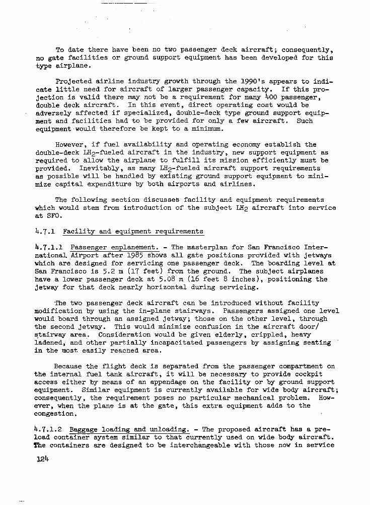
To date there have been no two passenger deck aircraft; consequently, no gate facilities or ground support equipment has been developed for this type airplane.
Projected airline industry growth through the lggOcs appears to indi- cate little need for aircraft of larger passenger capacity. If this pro- jection is valid there may not be a requirement for many 400 passenger, double deck aircraft. In this event, direct operating cost would be adversely affected if specialized, double-deck type ground support equip- ment and facilities had to be provided for only a few aircraft. Such equipment,would therefore be kept to a minimum.
However, if fuel availability and operating economy establish the double-deck LH;~-f’ueled aircraft in the industry, new support equipment as required to allow the airplane to fulfill its mission efficiently must be provided. Inevitably, as many LHz-fueled aircraft support requirements as possible will be handled by existing ground support equipment to mini- mize capital expenditure by both airports and airlines.
The following section discusses facility and equipment requirements which would stem from introduction of the subject LH2 aircraft into service at SFO.
4.7.1 Facility and equipment requirements
4.7.1.1 Passenger enplanement. - The masterplan for San Francisco Inter- nationa1,Airport after 1985 shows all gate posit.ions provided with jetways which are designed for servicing one passenger deck. The boarding level at San Francisco is 5.2 m (17 feet) from the ground. The subject airplanes have a lower passenger deck at 5.08 m (16 feet 8 inches), positioning the jetway for that deck nearly horizontal during servicing.
The two passenger deck aircraft can be introduced without facility modification by using the in-plane stairways. Passengers assigned one level would board through an assigned jetway; those on the other level, through the second jetway. This would minimize conf’usion in the aircraft door/ stairway area.. Consideration would be given elderly, crippled, heavy ladened; ‘and other partially incapacitated passengers by assigning seating in the most. easily reached area.
Because the flight deck is separated from the passenger compartment on the internal fuel tank aircraft, it will be necessary to provide cockpit access either by means of an appendage on the facility or by ground support equipment. Similar equipment is currently available for wide body aircraft; consequently, the requirement poses no particular mechanical problem. How- ever, when the plane is at the gate, this extra equipment adds to the congestion.
4.7.1.2 Baggage loading and unloading. - The proposed aircraft has a pre- load container system similar to that currently used on wide body aircraft. The containers are designed to be interchangeable with those now in service
124

t o i n s u r e ease of baggage and cargo transfer between different model wide body aircraf t . Since preloaded container doors are similar in configurat ion and s i l l heights do not exceed those now i n u s e (max DC-10 is 2845 mm (112 inches); less f o r L-1011 and 7471, existing loading equipment can therefore be expected t o be used.
S imi l a r cons ide ra t ions app ly t o t he bu lk p i t baggage doors so standard belt loaders can be used.
4.7;1.3 Lavatory service. - Present ly , a l l narrow body and wide body air- c r a f t have the i r l ava tory g round se rv ice pane ls wi th in 2.44 m (8 feet ) of t h e ground with the except ion of t h e 747 which has one aft loca t ion 4.57 m (15 f e e t ) from the ground. This one pa r t i cu la r pane l r equ i r e s a spec ia l l i f t for pos i t ion ing the opera tor c lose enough t o s e r v i c e t h e a i r p l a n e . The LH2- fue led a i rc raf t can be designed so lavator ies can be serviced with s tandard equipment.
4.7.1.4 Galley service. - Contemporary wide body a i rc raf t a re normal ly f i t t e d w i t h removable food and liquor modules i n t h e i r g a l l e y s . .These a i r c r a f t can be purchased with gal leys located e i ther on the passenger deck o r below in the preloaded container baggage sect ion. Narrow body a i r c r a f t always have galleys located on the passenger deck, but some of these a i rcraf ' t a r e f i t t ed w i th l a rge , p re loaded , do l ly movable modules while others use many small "picnic basket" type, hand carry-on containers.
Wide body a i r c r a f t are serviced by three type food t rucks; 1) a l a r g e van having a r o l l e r m a t floor with a convent ional scissor l i f t t o p o s i t i o n t h e van at the passenger level gal ley service doors; 2) a spec ia l module handl ing uni t that operates adjacent to the lower lobe container loader from which those ga l leys are serviced; and 3) a unit similar t o (1) above having a fold-down s o l i d f l o o r o v e r t h e r o l l e r mats capable of servicing ga l l eys i n a l l model a i r c r a f t . The l a t t e r , t he un ive r sa l t ype food t ruck , s a c r i f i c e s somewhat i n economy of manpower, se rv ice times, and maneuver- a b i l i t y . However, t h e u n i t i s i d e a l l y s u i t e d where a mixture o f a i rc raf t requi re se rv ic ing , genera l ly a t smaller s t a t i o n s . Because of the height and weight involved i n t h e s c i s s o r s l i f t units, it is necessary to provide s t ab i l i z ing dev ices on the chass i s as t h e van sides expose a. l a rge ,area /.too .. prevailing winds and j e t b l a s t s . The j e t blasts, o f t en t o ve loc i t i e s o f 145 lan (90 mph), have the po ten t ia l o f t ipp ing over h igh l i f t equipment.
The double-decked LHpfueled aircraft can be designed so food service can be provided either at t h e l o w e r l e v e l , o r t o a below-decks ga l ley . E leva to r s w i th in t he a i r c ra f t would then be used to move the suppl ies to the upper deck.
4.7 .l. 5 Cabin serv ice t ruck . - Specia l t rucks are requ i r ed fo r s e rv i c ing a i r c ra f t cab ins t o p rov ide t he supp l i e s of f'resh l i n e n , literature f o r t h e seat pockets, and necessary equipment for cleaning carpets, ash trays, seats, e t c . These u n i t s are general ly operated from the s ide o f t he a i r c ra f t oppos i te the j e t w a y . The present wide body cabin service supply truck would

probably service the lower deck of the LH2-fueled a i r c r a f t . Hcwever, e i t h e r an appendage would have t o b e added t o t h i s unit to ga in access t o t he uppe r deck or e l s e a specialized piece of equipment would have t o be designed. The present design, similar t o a food truck, l i f t s a 6.1 m (20 f o o t ) van to the passenger deck by means of a s c i s s o r s l i f t . The addi t iona l he ight requirement for the upper deck of the LH2-fueled a i r c r a f t will requi re a l a r g e r , more expensive unit.
The present van and crew s ize a l loca ted normal ly c lean the cab in in the des i red se rv ice times. Consequently, any new design should be predi- cated on the equ iva len t a l l oca t ion of supplies and personnel. . Many of the present units are equipped with a 5kW engine-driven generator to provide power for c leaning chores when sh ip power i s not ava i lab le . .I
4.7.1.6 Aircraft towing. - Tow. t r ac to r s a r e ava i l ab le t o hand le a i r c ra f t up t o one mi l l ion pounds gross weight. These machines are low i n p r o f i l e 1-58 m (62 inches) and can maneuver under t h e a i r c r a f t q u i t e e a s i l y . The a i r c r a f t i s genera l ly moved by connecting a tow b a r t o t h e f r o n t of the nose wheel. A t crowded ga te pos i t i ons t he t r ac to r can be postioned behind the nose wheel permitting a tow bar connection where t h e a i r c r a f t can be pulled back from the terminal (see Figure 30).
The nose wheel tow ba r a t t ach po in t s on t h e LH2 fue led a i rc raf t should be of the same design as contemporary a i rc raf t a l lowing s tandard tow bars t o be used interchangeably. Future models of tow t r a c t o r s may have the capabi l i ty o f towing the a i rc raf t a t normal t ax i speeds 48 t o 56 la (30 t o 35 mph) f o r moving t o and from t h e runway. Normal tow speeds are now about 10 km (6 mph).
4.7.1.7 Other required support equipment. - Water service can be provided in conjunct ion wi th ga l ley se rv ic ing by addition of a potab le water t ank to the food t ruck, by a separa te water serv ice vehic le , or by a ramp or jetway s e r v i c e f i t t i n g .
A n APU i s included as standard equipment aboard the study airplanes. Present day a i r l ine opera t ion endorses th i s concept as it l e n d s v e r s a t i l i t y t o t h e a i r c r a f t i n t he cha r t e r s t a t ions it can v i s i t and minimizes the s i z e of crews for ground support. Normally the APU provides 400 Hz power and pneumatics for cabin a i r condi t ioning and engine s tar t ing. However, t he s u b j e c t m y f u e l e d a i r c r a f t will no t r equ i r e t ha t amount of power f o r air conditioning because of the simple, nonmechanical refrigeration system which w i l l be employed. This w i l l provide s ignif icant advantage, not only in
I reduced energy but also in noise reduction a t t h e a i r p o r t .
4.7.2 Special equipment required f o r LH2 a i r c r a f t
4.7.2.1 Hydrant service vehicle. - Location of the fueling connection i n t h e t a i l cone provides the best s i tuat ion consider ing safety.aspects and cor re la t ion wi th o ther g round se rv ice ac t iv i t ies which will be performed concurrent ly with fuel ing. The hydrant service vehicle and 'associated plumb- ing should be sized to be capable of on-loading the mission f u e l i n t h e
126

allocated service time as indic'ated in the introductory paragraphs of this section. Other details of the fueling unit are discussed in Task 4. It is anticipated topping-off will be done with this unit in the event of a delay, mission change , or final fuel load change. 4.7.2.2 Defueling equipment. - In the event of a delay over six hours air- craft are normally removed from the gate. The maintenance facility could be used for the occasional requirement for defueling LH2 aircraft. A mission ,
change to a lesser distance or required fuel load is infrequent enough that the expense of special defueling equipment at the ramp could not be justified.
4.7.2.3 Leak detection equipment. - GH2 can be detected readily. If there are detectors installed on the line vacuum pumps and in the areas .around the fuel tanks, no &her equipment appears necessary.
4.7.3 Effect of aircraft configuration ~~ on maintenance and support requirements
4.7.3.1 Physical access between flight station and passenger compartment. - The internal tank aircraft has the flight deck separated from the passenger compartment by the forward fuel tank. Specific ground handling problems associated with this configuration include a means of crew enplaning and deplaning. A s considered in NASA CR 132.559, both lavatory and galley provisions will be made available to the flight deck and will require cor- responding support equipment. These items are mentioned in Section 4.7.1.1.
In current aircraft it has been found desirable that a qualified person (normally a member of the flight crew) be available for special service from time to time in the passenger compartment. Flight logs show various reasons as follows :
a. Fire in waste containers of galleys and lavatories.
b. Observe certain features of the aircraft during daylight hours.
1) Spoilers 2 ) Flaps (trailing and leading edge) 3) Ailerons 4 ) Engine reversers.
c. Mechanical and electrical problems in galleys and lavatories.
d. Quiet violent or drunk passengers.
e. Observe main gear-down locks.
Since none of these functions require flight training, it is concluded that presence of a member of the flight crew, per se, is not required. Alterna- tively, a senior hember of the cabin crew of the LH2 aircraft could receive special instrhctioh for these emergencies and could selve as the flight captain's representative in such situations.
. . . . " . . . . . . . "" ".

4.7.3.2 External tank aircraft. - The fuel tanks on the wing in the exter- nal tank configuration pose several problems. First, access to the aft passenger door by a jetway becomes exceedingly difficult without a design modification. Secondly, there is greater exposure to damage of the external tanks by ground vehicles as the tanks project beyond the leading and trail- ing edges of the wing. Lastly, general opinion among airline operators is that the presence of the external tanks obscure the passenger's view, sought by some, and highlight to other sensitive passengers that they are in a different type aircraft, leading to uneasiness and dissatisfaction.
5. PHASE I11 - CONCEPT DESCRIPTION
Preceding sections have described the basis for establishing the requirements for LH2 fuel at San Francisco International Airport (SFO) to permit its use in long range transport aircraft in 2000 A.D. The facilities and equipment needed to liquefy hydrogen, and to store and dispense it in accordance with postulated airline requirements at SFO, have also been described.
In this section the selected arrangement for these facilities and equipment, and the associated operating procedures, are described. In addi- tion, changes in design of the preferred LH2 fueled aircraft which has been used as a model for this analysis are suggested. The changes resulted from consideration of the handling and operational procedures which were found to be necessary or desirable in the use of LH2 fuel.
5 . 1 Task 10: Concept Arrangement and Description
The following narrative and illustrations summarize the work of Tasks 2 through 9 to depict a concept for converting San Francisco International Airport to accommodate limited use of LH2-fueled aircraft. The objectives of Task 10 were to: 1) describe a workable concept, 2) gain insight into the costs of adapting and operating the airport, and 3 ) provide a preliminary assessment of the problems or difficulties likely to be encountered in such a project. The concept is not represented as an optimum solution; in fact, as the concept developed, decisions were occasionally made which offered oppor- tunity to explore more fully the potential difficulties, rather than to develop the simplest solution.
5.1.1 Description of selected concept. - The physical alterations to the airport and its environs and the principal impacts on operations are described in this section. Section 5.1.2 discusses cost implications and Section 5.1.3 summarizes the requirements for facilities and equipment unique to the LH2 aircraft.
5.1.1.1 Fuel demand and energy supply. - Task 2 developed an estimate of the 1995-2000 route segments that would be potential users of the designated LH2 aircraft. A scenario was developed relating probable development programs and early production of the aircraft to priority city pairs and routes in.cl.uding SFO. Using extrapolation of current service patterns at SFO, a schedule for an average day in the peak month of the year 2000 was postulated
128

for the LH2-fueled aircraft. The schedule serves thirteen destinations with 70 flights operated by eight carriers, and represents about 41 percent of enplanements on CAB certificated services (excluding intrastate boardings).
Trip fuel requirements for the schedule were aggregated at approximately 7.68 kg/s (731.4 tons per day) (net fuel to engines). Refueling schedules were derived based on a fueling rate to accomplish design mission fuel transfer in 38 minutes, commensurate with current procedures.* This exercise produced refueling times ranging from about eight minutes for a Kansas City service to 31 minutes for a Tokyo flight. The demand schedules indicated that no more than four aircraft would need to be fueled simultaneously.
An evaluation of alternate supply methods in Task 3 concluded that the on-site liquefier offered the most attractive economics. Production of nearly 8.888 kg/s (846.5 tons/day ) of the liquid is required to supply the 7.68 kg/s (731.4 tons net fuel to the engines. To meet this requirement , four 2.625 kg/s capacity modules are programmed for the concept, providing Some reserve capacity (see Task 6). The gaseous hydrogen supply to the plant is assumed to be provided from a nearby pipeline. For convenience, the GH2 supply line is assumed to enter the airport site from a causeway constructed across the seaplane harbor.
During peak periods, all four modules will be producing LH2, consuming nearly 332 megawatts of electrical energy. For purposes of concept develop- ment, it has been assumed that the power is obtained commercially and can be furnished from the easement along the Bayshore freeway now traversed by high capacity transmission lines. Access to the airport LH2 liquefaction plant would be over the causeway as shown on Figure 32.
5.1.1.2 Liquefaction plant and storage facilities. - The site selected for concept development of the liquefaction and storage facilities is an unused plot on the bay side of the airport. The plot, of about 174,900 m2, is located between a large area currently used by American Airlines for maintenance facilities and two smaller plots used by a fixed base operator and UAL, respectively. Access is currently via a perimeter roadway serving several leaseholds around the seaplane harbor.
Liquefaction plant, substation, storage facilities, maintenance yard, and administration require approximately 202,000 &. The Defuel/Refuel Apron and related facilfties require about 52,600 I$, The concept illustrated in Figures 32 and 33 adapts the plant and storage layout of Task 6 to the selected plot. Twenty acres of land are to be reclaimed adjacent to the site in the shallow seaplane basin, to provide the necessary 255,000 m2. Minor liberties were taken with the property subdivision line on the west edge of the plot to simplify layout.
*It w a s subsequently pointed out that for future designs airline preference is to reduce the design mission refueling time to 30 minutes.
I

The airport perimeter road will be relocated to the outer edge of the landfill to maintain access to the American facility. The road will join the causeway envisioned across the old seaplane basin from the peninsula, in the area of the existing fuel storage'facilities, to provide direct vehicular access to the site and a route for the GH2 supply and power transmission lines.
The operation of the liquefaction plant is described in Section 4.4. Gaseous hydrogen feedstock enters the plant from the causeway and is intro- duced into the H 2 feed compressors. From there it goes through purification, recycle compression, liquefaction, and is then stored in five 3785 m3 (1 000 000 gal) vacuum-jacketed spherical vessels. Air separation facilities are provided to supply liquid nitrogen needed as a heat sink in the H2 liquefaction process.
The LH2 storage tanks are located along the eastern edge of the site and the LH2 distribution system to the passenger loading terminals leaves the site at this point. Aircraft access to the apron area is via Taxiway " C " . A parking and service area for the hydrant fuelers and LH2 tanker trucks needed for special fueling service in maintenance areas is adjacent to the apron, as these vehicles require direct access to the aircraft pavements.
Existing landfill in the area is probably not suitable for founding many of the elements of the plant. Piles will be required for these facilities, as is common for most of the buildings at the airport.
5.1.1.3 I Gate fueling. - Consideration of the location and nature of the air- craft fueling operation is fundamental to the identification of a feasible concept for LH2 aircraft/airport integration. Task 4 presented an evaluation of alternative fueling procedures and selected the terminal gate procedure as most appropriate for SFO. This concept is depicted in Figures 32 and 33.
The fueling operation will be performed at the terminal gate by a f'ueler vehicle (Figure 17) providing the necessary interface between a hydrant point of supply and the aircraft fuel system. It has been generally concluded that fueling of LH2 aircraft at the gate will not seriously alter ground servicing procedures or times, relative to current wide-bodied aircraft. However, development of an optimum ground service operation will require a much more definitive analysis of the possibilities which exist than time has permitted in the present study.
5.1.1.4 Distribution system. - In Task 4 it was determined that 19 of the 81 terminal gates planned at SF0 will be required to serve LH2-fueled air- craft. This requirement was established by translating the LH2 schedules produced in Task 2 into gate demand by individual carrier. The gate positions which were assumed f o r purposes of defining the LH2 distribution route are shown on Figure 33 as the darkened airplane outlines. Designation of these facilities by air carrier is shown on Figure 32.
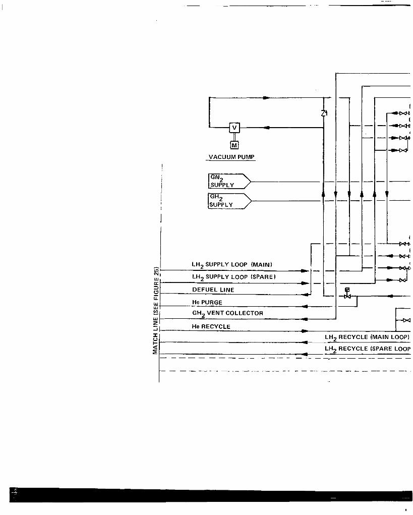
VACUUM PUMP
LH2 SUPPLY LOOP (MAIN) I 31 - W LH2 a
2 c
SUPPLY LOOP (SPARE)
3 -
DEFUEL LINE L
Y
W u.
GH2 VENT COLLECTOR v)
He PURGE A - - e - - L '
J
u c - H e RECYCLE - 1 - r
a LH2 RECYCLE (SPARE LOOP
LH2 RECYCLE (MAIN LOOP) A
E A

DEFUEL
VENT
FILL
10" V.J. ( 2 5 . 4 cm) A GH2 VENT COLLECTC
10"V.J. ( 2 5 . 4 cm) - LH2 SUPPLY LOOP (M
10" V.J. ( 2 5 . 4 cm)
"_ - -. -
." ~ ~
AIRCRAFT TANKS
NO. 1 AIRCRAFT FUEL TANK CHILLDOWN STATION + REFUELING AND DEFUELING STATION
a=
I
NO. 2 AIRCRAFT FUEL TANK . CHILLDOWN STATION + REFUELING
HYDRANT FUELING TRUCK HYDRANT PIT
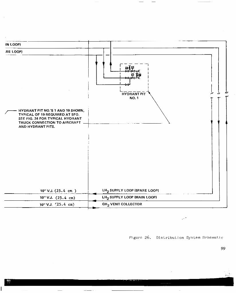
I""" HYDRANT PIT\ 1
7 HYDRANT PIT NO.'S 1 AND 19 SHOWN, TYPICAL OF 19 REQUIRED AT SFO. 1 SEE FIG. 24 FOR TYPICAL HYDRANT i TRUCK CONNECTION TO AIRCRAFT AND HYDRANT PITS. +---
.!J
10" V.J. (25.4 cm )
GH2 VENT COLLECTOR 10" V.J. (25.4 cm)
LH2 SUPPLY LOOP (MAIN LOOP) IO" V.J. (25.4 cm)
I - LH2 SUPPLY LOOP (SPARE LOOP)
1 4
~. ." . ~~ ~~ - 1 -
-
Figure 26. Distribution System Schematic
99

'..
L-"
rnorosm mmnoacm
SAN FRANCISCO BAY
0 6.10 meters
32. LH; For
Facility
SF0
I n s t a l l a t i o n
131


p
f
:ers Figure 33. LH2 Dis t r ibu t ion System and Gate P o s i t i o n s a t SF0
13 3
.-
. .

While the po ten t ia l for re .duc ing LH2 service requirements through shared gate usage and rescheduling is recognized, it cannot be presumed t h a t t h e c a r r i e r s w i l l be wi l l ing to share ga te ass ignments or t o use terminals which are phys ica l ly separa te from t h e i r Jet A a c t i v i t y areas. Furthermore, the p ro jec t ed f l i gh t s chedu les a r e p red ica t ed on the assumption of a na t iona l commitment t o t h e u s e o f l i q u i d hydrogen as f u e l f o r commercial t r anspor t a i r c r a f t . S i n c e t h e n a t u r e o f t h i s commitment i s for ultimate t o t a l con- v e r s i o n t o t h e new fuel, it fo l lows t ha t u l t ima te ly su f f i c i en t LH2 f a c i l i t i e s will be ava i lab le at SF0 t o s e r v i c e t h e t o t a l g a t e demand as determined.
The ga te pos i t ions des igna ted for LH2 serv ice (F igure 3 3 ) were genera l ly select-d on the basis of minimizing impact on planned gate configuration and apron maneuvering and parking areas required for aircraft and assoc ia ted equipment. The higher length/span ra t io of the LH2 a i r c r a f t (1.26 compared ' :* t o 1.18 f o r a 747) suggests some potential advantage to an angle parking conf igu ra t ion t o minimize. impact on planned aircraft maneuvering and posi- t ion ing c learances . However, due to t he pa r t i cu la r na tu re o f t he t e rmina l configurat ion a t SF0 and the l oca t ion o f t he LH2 ga tes wi th in the to ta l apron terminal complex, t h e r e a r e r e a l l y no bene f i t s t o be de r ived by angle parking. In fac t , angle park ing may ac tua l ly p roduce d i sbenef i t s in t e rms of addi t iona l terminal frontage and apron area requirements (Ref. 1 0 ) .
. ...- :. . q
"i:g:!$ 1,. I !
Apron taxilane clearance requirements were analyzed in consideration of the area in the fueling zone (27.43 m (90 f t ) ) suggested as BeRng res t r ic ted t o exelude spark igni t ion vehicles . This graphic analysis , Figures 34 and 35, indicates that imposit ion of such a r e s t r i c t i o n w i l l not seriously impact f u t u r e a i r c r a f t p o s i t i o n i n g , however, apron movement w i l l be l imi t ed t o s ing le t a x i l a n e c a p a b i l i t y between p i e r s or s a t e l l i t e s . It should be noted, how- ever , that the planned configurat ion i s s imi la r ly l imi ted for convent iona l ly fue led wide body a i r c r a f t .
The freedom of s e l ec t ion o f LH2 ga tes was l i m i t e d t o t h e e x t e n t t h a t t h e developed gate requirements are a i r l ine specif ic and that the gates designated f o r LH2 serv ice must necessar i ly be those ass igned for use by wide body air- c r a f t . A t t he same t ime, however, it was a l so necessary to cons ider the .i
compatibi l i ty of the LH2 gate arrangement with respect to the loop concept 'J
of LH2 d i s t r i b u t i o n .
,..
The bas ic LH2 distribution system concept employs a c i r c u l a t i n g l o o p i n which LH2 (from a s torage t ank) i s cont inuously c i rculated past each of t he t.
19 hydrant stations and returned to the storage system. The LH2 will be c i r - cu la ted in the loop a t su f f i c i en t f l ow r a t e so t h a t any hea t l eak i n to t he dis t r ibut ion system w i l l r e s u l t i n a l iqu id t empera ture r i se o f no t more than 2'F a t t h e last hydrant s ta t ion on t h e loop , The excess c i r cu la t ing l i qu id i s then re turned to s torage and in t roduced in to a vented storage tank to be boi led back to s a tu ra t ion cond i t ions . The advantages of the loop concept are the v i r tua l e l imina t ion of f u e l system chill-down time and the immediate avai labi l i ty of subcooled LH2 a t each hydrant s ta t ion.
. .
. . .;.

Figure 34. Apron Taxilane Clearances (South)

Figure 35. Apron Taxilane Clearances (North)

As d e t a i l e d i n Task 7 , t he d i s t r ibu t ion sys t em ac tua l ly cons i s t s of two p a r a l l e l LH2 supply loops. During periods of peak demand both loops w i l l be in o p e r a t i o n , c i r c u l a t i n g s u f f i c i e n t LH2 past t h e 19 h y d r a n t s t a t i o n s t o service t h e peak fuel demand. However, during most of the year fuel demand w i l l r equi re the opera t ion of on ly one supply loop, with the other providing a backup supply system. The dual loop system offers advantages i n terms o f providing system redundancy i n c a s e o f failure in t he p r imary supp ly l i ne and w i l l s i gn i f i can t ly r educe hea t l eak l o s ses ove r a one-line system s i z e d f o r peak f u e l demand.
Gaseous hydrogen vented from both the aircraft and ground systems w i l l be recovered by a GH2 co l l ec t ion l oop t ha t i s rea l ly jus t another e lement o f t h e t o t a l LH2 d is t r ibu t ion sys tem. Cold vent gas w i l l be c a p t u r e d i n a vent co l l ec t ion heade r t ha t pa ra l l e l s t he supp ly l oop and r e tu rned t o t he l i que f i e r for re - in t roduct ion in to the l iquefac t ion process .
It i s proposed that t he LH2 d is t r ibu t ion sys tem ( inc luding two supply l i n e s and a ven t co l l ec t ion l i ne ) be rou ted below grade i n a concre te l ined open trench covered with s t ee l g ra t ing . From the s tandpoin t of v e n t i l a t i o n considerations and maintenance requirements, and i n o r d e r t o p r o v i d e a high degree o f l ine access ib i l i ty , it i s cons idered des i rab le tha t t h e d i s t r ibu - t ion loop be rou ted pr imar i ly in open trench. Although it i s recognized that an optimized design could conceivably identify sections where underground ( t u n n e l ) l i n e r o u t i n g would be acceptable , it i s f e l t t ha t app l i ca t ion o f t he open trench concept t o t h e e n t i r e d i s t r i b u t i o n l o o p i s en t i r e ly f eas ib l e and preferable during the ear l ie r periods of use of t h e f u e l . System improve- ments and modifications are made w i t h r e l a t i v e ease and hazards of col lect ion of an explosive GH2 a i r mixture are v i r t u a l l y n i l .
5.1.2 __ Summary .. of cost implicat ions. - Evaluation of the problems and require- ments of handl ing LH2 f u e l e d a i r c r a f t a t a des igna ted a i rpor t must necessa r i ly include considerat ion of the economic impl ica t ions o f p rovid ing for the new f u e l . Order of magnitude estimates of cost, where such costs could readily be i d e n t i f i e d , were developed for major elements of the LH2 system consistent w i th t he l eve l o f s tudy e f fo r t . Other elements have simply been identified as c o n s t i t u t i n g s i g n i f i c a n t c o s t ’ i t e m s t h a t must be considered in developing t h e LH2 system and no attempt has been made t o p u t a value on these items. However, it i s f e l t t h a t t h e c o s t s summarized in t he fo l lowing are s u f f i c i e n t t o permit a first order assessment of the economic implicat ions of a na t iona l commitment t o t h e u s e o f LH2 as a fuel for long range commercial transport a i r c r a f t .
5 .1 .2 .1 Capi ta l cos t s . - Major capi ta l investment w i l l qui te obviously be requi red in the l i q u e f a c t i o n p l a n t and s to rage f ac i l i t i e s , and i n t he LH2 dis t r ibut ion system. The cos t impl ica t ions o f p rovid ing these fac i l i t i es are summarized below:
~. Liquefaction/storage - f a c i l i t i e s and equipment. - The e s t i m a t e d t o t a l Capital investment for the hydrogen l iquefact ion plant and s t o r a g e f a c i l i t y i s $239 mil i ion. Addit ional capi ta l requirements , including in te res t during

cons t ruc t ion , s ta r tup cos ts , and working c a p i t a l add another $69.6 m i l l i o n t o b r i n g t h e t o t a l c a p i t a l r e q u i r e m e n t t o $308.6 mil l ion. This w i l l provide a f a c i l i t y which has a capaci ty of 10.50 kg/s (1000 tons/day) of l iquid hydrogen in to s to rage p lus a tank farm having a to t a l capac i ty o f 1 8 927 m3 ( 5 000 000 gal) of l iquid hydrogen. These costs are f o r a completely i n s t a l l e d and ready-to-operate plant and include the pieces of major equip- ment l i s t e d i n Table X I X plus a l l the necessary supporting and auxiliary equipment requi red for opera t ion of the fac i l i ty .
Based on peak-month r equ i r emen t s , t he l i que fac t ion f ac i l i t y i s oversized by about 18 percent when using eff ic ient , h igh-speed fuel ing operat ions , but only by 11 t o 12 percent based on more r ea l i s t i c , ave rage fue l ing . Whether or not any significant cost reduction can be achieved by reducing plant c a p a c i t y t o match demand depends t o a l a rge ex ten t on the design philosophy concerning the number o f d i f f e r e n t module s i z e s t o b e made ava i lab le . A s i n - gle s tandard capaci ty module has advantages in reducing engineering design and procurement cos t s . If it were decided t o design four identical produc- t i on modules t o provide 9.45 kg/s (900 tons /day) to ta l capac i ty , the unit cos t fo r t he LH2 product would be expected t o decrease by approximately 2 t o 2-1/2 percent .
Based on year-round average LH2 requirements of approximately 6.93 kg/s (600 tons/day) , t he p l an t i s oversized by nearly 52 percent . Hpwever, a peak sharing arrangement in which l iquefac t ion capac i ty i s reduced and s torage capacity is correspondingly increased does not appear t o produce an economic advantage.
Land requirements. - The l ique fac t ion p l an t and s torage f c i l i t y concept discussed in Sect ion 5.1.1.2 w i l l require approximately '$3100 m of land fill i n the seaplane basin north of t h e des igna ted s i t e (F igu re 33) . The concept a lso envis ions a causeway across the seaplane basin provid ing access to the s i te and a rou te fo r power t ransmission l ines and GH2, supply.
'3:
Easements along the north airport boundary w i l l a lso be required for t h e rout ing of power t ransmiss ion l ines from nea r t he Bayshore Freeway t o t h e l i q u e f a c t i o n f a c i l i t y .
Although it i s f e l t t ha t t he cos t o f r ec l a imed l and , causeway, and required easements may not be s ign i f icant i n terms of to ta l sys tem cos t , these e lements are basic to the concept and obviously constitute important considerat ions in s i te development , and assessment of environmental impact.
Power supply. - As mentioned previously, it has been assumed t h a t t h e e l ec t r i ca l ene rgy (=332 megawatts) necessary for the production of LH2 w i l l be obtained commercially and can be furnished from t h e causeway indicated on Figure 32. While no attempt has been made t o e s t i m a t e t h e a c t u a l c o s t o f f ac i l i t i e s fo r s a t i s fy ing t h i s ene rgy r equ i r emen t , it i s obvious that the impact of t h i s demand l e v e l on the avai lable energy supply w i l l be s ign i f i can t .

Distribution system. - The c a p i t a l c o s t s o f t h e d i s t r i b u t i o n s y s t e m are der ived pr imari ly from the fol lowing:
0 Trench system construction
0 LH2 d i s t r i b u t i o n equipment located i n t h e s t o r a g e area
0 I n s t a l l a t i o n o f LH2 d i s t r i b u t i o n l i n e s
0 Hydrant p i t i n s t a l l a t i o n s
0 I n s t a l l a t i o n of vent gas collection system
The de ta i l s o f t rench des ign a re assumed t o remain re la t ive ly cons tan t over the length of the dis t r ibut ion system and, for purposes of this analysis , no attempt has been made t o optimize the design i n terms o f v a r i a b l e l a t e r a l and ve r t i ca l l oads . A heavy s tee l g ra t ing des igned f o r a i r c r a f t l o a d s w i l l be required in all apron areas, as well as runway and t a x i w a y crossing. Although t h e heavy gra t ing should log ica l ly ex tend to the limits of runway sa fe ty a r eas , t he re a r e po r t ions o f t he t r ench between taxiways where a s ign i f i can t ly l i gh te r g ra t ing des ign would probably be acceptable. However, t he add i t iona l cos t o f t he heav ie r g ra t ing seems r e l a t ive ly i n s ign i f i can t when consider ing the increased margin of safety provided by insur ing aga ins t violat ion of the t rench by an a i r c r a f t o r a heavy vehicle such as a crash- f i re-rescue (CF'R) t ruck . As a resu l t , the es t imated cos t o f t rench cons t ruc- t i o n r e f l e c t s t h e u s e o f a heavy s t e e l g r a t i n g ( d e s i g n e d f o r a i r c r a r t l o a d s ) over the en t i re l ength o f the d i s t r ibu t ion sys tem.
The cost of t rench construct ion i s estimated to be approximately $5 800 000 based on the cos t s of excavation and backfil l , concrete trench and necessary expansion joints, dewatering system, and steel grating.
Within the LH2 s torage a rea there i s a subs t an t i a l amount of equipment t h a t i s rea l ly par t o f the d i s t r ibu t ion sys tem. This includes piping, pumps , and valves associated with the primary distribution loop, as w e l l as t h e equipment necessary t o s e r v e t h e d e f u e l / r e f u e l f a c i l i t y . The est imated cost o f t h i s equipment is approximately $5 954 000.
As discussed in some d e t a i l i n t h e Task 7 n a r r a t i v e , t h e LH2 d i s t r i b u t i o n system consists of two c i r cu la t ing d i s t r ibu t ion l oops , each w i th s t a in l e s s s teel , vacuum-jacketed supply and return l i n e s of 2 5 . 4 and 20.3 cm diame- ters, respec t ive ly . The c a p i t a l c o s t of LH2 supplyTGeturn lines and asso- c ia ted valves and f i t t i n g s i s estimated to be approximately $12 743 000.
The investment i n h y d r a n t p i t i n s t a l l a t i o n s i s der ived pr inc ipa l ly from the cos ts o f p ipe risers, s e r v i c e i s o l a t i o n valves, control valves, couplings, and o the r necessa ry f i t t i ngs . The t o t a l e s t i m a t e d c o s t of ' i n s t a l l i ng t h i s equipment at t h e 19 designated hydrant s ta t ions is approximately $960 000.
The major element of the vent gas collection system, as d e t a i l e d i n t h e Task 7 narrative, i s a i25.4 Cm vacuum-jacketed vent collection header that p a r a l l e l s t h e LH2 supply loop. The system also includes a smaller 10.2 cm vent header serving the maintenance area. The GH2 vent collectors and associated valves and f i t t i n g s can be ins ta l led a t an est imated cost of approximately $5 917 000.
S m a r i z i n g t h e above m a t e r i a l , t h e LH2 d is t r ibu t ion sys tem w i l l r equi re a total es t imated capi ta l investment of approximately $31 374 '000. In addi- t i on¶ cap i t a l i nves tmen t w i l l be required for f i v e or s ix hydrant fue le r vehicles at an est imated cost of approximately $70 000 each.
5.1.2.2 Operating costs of LH2 system. - Opera t ing cos ts for the l iquefac t ion /s torage complex are p resented i n d e t a i l i n t h e Task 6 narra- t i v e . The major implicat ions of o p e r a t i n g c o s t s r e l a t i v e t o t h e unit cost of LH2 product ion are summarized in the mater ia l tha t fo l lows . Other oper - a t i n g and maintenance cost considerations are a l so no ted .
L ique fac t ion md s to rage f ac i l i t y . - The es t imated to ta l annual opera t ing cost (base case) for t h e hydrogen l i que fac t ion p l an t and s t o r a g e f a c i l i t y i s $133.6 mil l ion based on a total annual production of 2.1071 x 10 8 kg (232 250 t o n s ) , Maintenance i s included i n t h i s f i g u r e and amounts t o $3.9 million annually which equals 1 .6 percent o f to ta l p lan t inves tment . For the base case, the major i tems of operating costs, comprising 89.7 percent o f t h e t o t a l , are t h e gaseous hydrogen feedstock a t $76.4 mi l l ion and elec- t r i c i t y at $43.5 mill ion. Hydrogen feedstock w a s assumed t o c o s t 36.27$/kg (16.454/1b) of liquid product and t h e e l e c t r i c i t y was assumed t o c o s t $0.02/kWh fo r t he base ca se . The feedstock cost i s typ ica l o f e s t ima tes fo r hydrogen der ived f rom gasif icat ion of coal in the 1985 - 2000 time period, wh i l e t he cos t o f e l ec t r i c i ty w a s a r b i t r a r i l y s e l e c t e d t o r e p r e s e n t p u r c h a s e d e l e c t r i c i t y i n t h e same time period. The above est imates do not include the cos t of t h e d is t r ibu t ion sys tem, nor do they assume recovery of the vented gas. These i tems are included in the cost breakdown shown i n Section 5.1.2.3.
Distribution system. - The cos ts o f opera t ing the LH2 dis t r ibut ion system a re bas i ca l ly t he LH2 losses incurred during system operation. It i s s ign i f - i can t t o no te t ha t t he hea t l eak i n to t he sys t em i s constant no matter what t h e l iqu id f low rate. In other words, losses are occurring continuously whether or not there i s demand for fue l . This , o f course , ra i ses an i n t e r - es t ing ques t ion ; "How w i l l system operating losses (costs) be accounted for, and on what b a s i s w i l l they be ass ignable to t h e c a r r i e r s ? "
While the depth of the present analysis i s g e n e r a l l y n o t s u f f i c i e n t t o permit detai led evaluat ion of the cost o f maintaining the LH2 d i s t r i b u t i o n system, the specialized nature of the technology associated with handling l iquid hydrogen would suggest a cos t l eve l o f two t o t h r e e t i m e s t h a t of maintaining a Jet A f'uel system.
Major impact on o the r a i rpo r t ope ra t iona l and maintenance activity would probably only occur should the airport assume opera t ing respons ib i l i ty for

the l iquefac t ion , s torage and d i s t r ibu t ion sys tem. It is suggested, however, t h a t t h e s e f a c i l i t i e s might best be operated by some o t h e r e n t i t y s p e c i a l - i z i n g i n cryogenic processes and perhaps extended t o include contract cryo- genic services as suggested i n Section 5.1.3.3.
Refueling of a LH2 a i r c r a f t a t t h e t e r m i n a l g a t e , as pos tu la ted , w i l l r equi re two men and one major piece of equipment while the comparable Jet A ref 'ueling operation requires four men using two pieces of equipment (assunled fue l ing at both wing points - two hydrant fuelers a t two men each). Based on cur ren t ly available . in format ion , the re fue l ing times f o r t h e two fue l s should not be appreciably different. Until more conclusive information can be developed, it i s probably safe t o assume t h a t t h e g a t e r e f u e l i n g w i t h LH2 should be no more' cost ly than current procedures using Jet A fuel , consider- ing on ly the re fue l ing opera t ion cos ts .
5.1.2.3 -___- Liquid hydrogen cost. - The estimates of the investment and operating c o s t s f o r t h e l i q u e f a c t i o n , s t o r a g e , and d i s t r i b u t i o n f a c i l i t y p o s t u l a t e d f o r SF0 which were p re sen ted i n t he p rev ious s ec t ion a r e summarized i n Table XXIV. The question marks i n d i c a t e t h a t t h e economic implicat ions of these elements may be s ign i f i can t , and t h a t f u r t h e r e f f o r t i s needed t o ident i fy properly their magni tude.
The investment and operating costs shown i n t h e t a b l e p r o v i d e a b a s i s for ca lcu la t ion of the p roduct ion cos t o f l iqu id hydrogen de l ivered to the a i r c r a f t u s i n g t h e SF0 f a c f l i t y . The bas i s fo r t he cos t ca l cu la t ions i s presented in Table XIV.
The method of ca lcu la t ion involves the use of re la t ions g iven in Sec t ion 4.1.7 as follows: The equat ion for present value of the product ion cost i s given i n Equation (12).
PV = 4.1887 ( A O C ) + 0.95956 (I) + 0.52 ( s ) + 0.9666 (w) (12)
The present value o f annual income r e q u i r e d t o meet production costs i s given by the fol lowing expression:
W = 4.1887 (AI) (13)
Equating (12) and (13) and solving for annual income gives:
A I = AOC + 0.22908 (I) + 0.12414 ( S ) + 0.23067 (W) (14)
Unit production cost i s obtained by dividing Equation (14) by the annual production rate. Total annual production required with the 15.7 percent operations loss r a t e i s 2.10706 x 10⁸ kg (232 265 t o n s ) . S u b s t i t u t i n g c o s t data into Equat ion ( 1 4 ) gives $213 019 000 for annual income and a u n i t c o s t of $0.943/kg ($0.4274/1b) f o r t h e l i q u i d hydrogen produced i n t h e s i t u a t i o n where the re i s no recovery of L Q b o i l o f f .

TABU3 XXIV. SUMMARY OF INVESTMENT AND OPERATING COSTS (LH2 System - San Francisco International Airport) '
System Element Capital Cost
( $ 106)
Annual Operating and Maintenance
cost ( $ 106)
Energy Supply Facilities l o Power easements and
transmission structures
o GH supply pipeline 2
Liquefaction/storage plant
Disiribution system
o Trench construction
o Piping/valves, etc.
Hydrant fueler vehicles
Total
(Included in cost of electric power. )
(Included in cost of feedstock.)
308.6
25.6
0.4
340.4
133.6"
Not Significant
?
?
133.6
*Includes GH feedstock and electric power (see section 4.4). 2

I
However, t h e vent gas recovery system, which i s inc luded i n t he cos t o f the d i s t r ibu t ion sys tem, w i l l . r ecover essent ia l ly a l l t h e LH2 b o i l o f f , e x c e p t t h a t l o s t i n f l i g h t . The recoverable GH2 amounts. t o 91.5 percent of t h e t o t a l e s t i m a t e d loss of 15.7 percent . Recovery of th i s co ld gas reduces t h e amount of feedstock gas required and a l so r ep resen t s a valuable source of re f r igera t ion . Us ing the above equations the corrected base case cost of l i q u i d hydrogen was c a l c u l a t e d t o be $0.887/kg ($0.4026/1b) when 91.5 percent of the vent gas i s recovered.
The base case un i t cos t i n the preceding paragraph i s based upon a hydrogen feedstock cost of $0.363/kg ($0.1645/1b) of liquid hydrogen pro- duced and an e l e c t r i c i t y c o s t o f 2.04/kWh. To permit the determination of l i q u i d hydrogen cos ts for o ther va lues o f feeds tock and e lec t r ic i ty , F igure 36 i s p resen ted i n which t h e c o s t o f e l e c t r i c i t y i s var ied from z e r o t o 4.04/kWh and the cost of feedstock i s var ied from $0.11 t o $0.76/kg ($0.05 t o $0.35/lb). The uni t cost of l iquid hydrogen var ies from $0.566 t o $1.442/kg ($0.257 t o $0.654/1b) over this range of feedstock and e l e c t r i c i t y c o s t s . It i s assumed t h a t a l l investment and operat ing costs are included in the cost of the feed- s tock and e l e c t r i c power, i .e . , the cost of the gas product ion faci l i ty , gas p ipe l ine , power generat ion, power subs t a t ion , e t c . , are a l l accounted for in the p r ices pa id for the . GH2 and t h e e l e c t r i c i t y . I n t h i s manner the implica- t ion of these costs , once determined, can be used to f ind the f inal unit cos t of the delivered hydrogen.
A breakdown of the base case cos t o f LH2 is t abu la t ed i n Table XXV which shows the cont r ibu t ion of each cos t e lement to the to ta l un i t cos t o f liquid hydrogen. The three parameters which have the g rea tes t impact on the uni t cos t a re :
0 The cost of the hydrogen gas feedstock del ivered to the l iquefact ion f a c i l i t y .
0 The cos t o f purchased e lec t r ic i ty .
0 Capi ta l inves tment for the l iquefac t ion and s t o r a g e f a c i l i t y .
Operat ing costs contr ibute $0.5790 kg ($0.2626/1b) which is equivalent t o 65.2 p e r c e n t o f t h e t o t a l u n i t c o s t o f $0.8877 kg ($0.4026/1b). There- fore, the operating cost i tems which have a major impact on t h e c o s t of l iqu id hydrogen in the overa l l cos t p ic ture are feedstock a t 35.8 percent and e l e c t r i c i t y at 22 .1 pe rcen t o f t he t o t a l un i t cos t . E f fo r t s at t o t a l c o s t reduction w i l l be most f ru i t f ' u l ly app l i ed i n t he r educ t ion o f t he cos t o f these two p lan t inputs as w e l l as e f f o r t s i n reducing plant investment s ince these th ree items col lect ively account for 92.7 percent of the total cost of l iquid hydrogen.
Manpower requirements for operation, maintenance and supervision of the f ac i l i t y t o t a l 103 pe r sons . Inc luded a r e 84 s h i f t p e r s o n n e l , 10 off ice per- sonnel, 5 technical personnel and 4 supervisory personnel. Total labor Costs, salaries, adminis t ra t ion and overhead add only 1.2 percent t o t h e f i n a l cos t .

1.60
1.40
1.20
(Y
5 0 < . I .OO L o ,
I - - =
0.80
0.60
0.40 L
0 1985 TECHNOLOGY 0 LIQUEFACTION, STORAGE & DISTRIBUTION
0 VENTED GAS RECOVERY INCLUDED 0 BTU COST BASED ON LOWER HEATING
VALUE OF 119,895 kJ/kg (51,590 Btuhb)
INVESTMENT AND OPERATING COSTS INCLUDED
12
I1
IO
9
a 8 3
7
6
5
Q
1 .o 2.0 3.0
COST OF ELECTRICITY - $/kwh
4.0
Figure 36. E f f e c t o f E l e c t r i c Power and Hydrogen Gas Feedstock Costs on Unit Cost of LH2

TABLE XXV. BASE COST OF LIQUID HYDROGEN AT SF0
0 Feedstock cost = $0.363/& ($0.1645/1b)
0 Electric parer cost = 2$/kWh
Operating Cost:
Feedstock*
Electric Power
Labor, Administration and Overhead
Chemicals, Supplies, Water, Taxes, and Insurance
Subtotal
Capital Investment:
Liquefaction and Storage Facility Investment
Distribution System Investment
start-up costs
Working Capital
Subtotal
0.3177
0.1965
0.0108
0.0540
0 5790
0.2600
0.0346
0.0040
0.0101
0.3087
0.8877
(0 ~441)
(0.0891)
(0.0049)
(0.0245)
(0.2626)
(0.1179)
(0.0157)
(0.0018)
(0.0046)
(0.1400)
(0.4026)
Percent
35.8
22.1
1.2
6.1
65.2 -
29.3
3.9
0.45
1.15
34.8
100
*Cost of feedstock ( G H 2 ) shown is adjusted to account for vent gas which is recovered and reliquefied.

The use of four 2.63 kg/s (250 TPD) p l a n t modules r e s u l t s i n a l a rge r - than-needed l iquefac t ion fac i l i ty . Based on year-round average capacity of 6.98 kg/s (665 TPD) it i s oversized by about 50 percent . However, i f peak- month fue l r equ i r emen t s a r e t o be me t , e i t he r t he p l an t must be s i zed fo r peak-month operat ions or addi t iona l s torage capac i ty must be provided. If t h e p l a n t i s t o b e s i z e d t o p r o v i d e t h e 7.68 kg/s (731.4 TPD) fue l require- ments p lus t he 15.7 percent opera t ions losses for a 350 day opera t ing year , it must have a to t a l capac i ty o f 9.27 kg/s (883 TPD) . The reduction i n un i t cos t r e su l t i ng from capi ta l investment for a 9.45 kg/s (900 TPD) vs a 10.50 kg/s (1000 TPD) f a c i l i t y would amount t o 2.76$/kg (1.25$/1b).
If, on the o ther hand , one were t o adopt a peak-shaving method of oper- a t i o n b y i n s t a l l i n g a d d i t i o n a l s t o r a g e t a n k s t o accommodate t h e s h o r t f a l l during peak-month opera t ion , the l iquefac t ion fac i l i ty could be reduced in s i z e . Assuming the extreme condition where the plant i s s u f f i c i e n t l y l a r g e t o produce only the average year-round requirement of 6.98 kg/s (665 TPD), it would be necessary to p rovide an addi t iona l 19 s torage t anks o f 3785 m3 (1 000 000 gal) capaci ty , each. These would cost $76 000 000 compared with a $75 000 000 reduction i n plant investment. Thus, there i s e s s e n t i a l l y no economic'incentive for one concept over the other. Furthermore, since the capi ta l inves tment for bo th s torage t anks and l iquefac t ion p lan t a re essen- tially l inear wi th capac i ty , the conclus ion i s va l id over the range of capaci t ies involved, One has almost complete freedom of choice t o i n s t a l l e i ther l iquefac t ion capac i ty o r s torage capac i ty wi thout se r ious economic penalty.
The 10.50 kg/s (1000 TPD) p l a n t s i z e which has been assumed provides a 13.'3 percent margin of over-capacity based on peak month operat ions. It i s therefore capable of handl ing an increase over the projected l iquid hydrogen fueled a i r t r a f f i c . A considerable increase i n t r a f f i c cou ld be accommodated by t h e a d d i t i o n o f s t o r a g e t a n k s t o t h e e x i s t i n g f a c i l i t y t o p r o v i d e a peak shaving operation.
5 . 1 . 3 S p e c i a l f a c i l i t i e s and equipment. - While it i s generally concluded t h a t t h e demand f o r t o t a l l y new and unique facility/equipment concepts i s not extensive, the use of LH2 f u e l i n air t r anspor t s e rv i ce w i l l c e r t a in ly w a r - r a n t s p e c i a l f a c i l i t y and equipment cons idera t ions re la t ive to the fo l lowing:
0 Operation of the LH2 fuel system
0 Aircraf t ground support services
0 Aircraft maintenance
The spec ia l and unique requirements of these act ivi t ies are ident i f ied and discussed i n some d e t a i l i n t h e n a r r a t i v e material o f Tasks 7 , 8 and 9 . The primary facil i ty/equipment considerations, as wel l as some of the s t i l l unresolved quest ions re levant to those requirements , are summarized i n t h e mater ia l tha t fo l lows .
146

5.1.3.1 Fuel system operations. - Dis t r ibu t ion o f LH2 t o t h e 19 terminal gates presents some unique problems not previously encountered i n LH2 systems
schedul ing constraints demand system o p e r a t i n g f l e x i b i l i t y t h a t w i l l be derived primarily from new appl icat ions of exis t ing technology, but w i l l a l s o require consideration of new concep t s o f f ac i l i t i e s , equipment , and procedures necessary for the safe and e f f i c i en t hand l ing o f l a rge quan t i t i e s o f LH2. These requirements are no ted b r i e f ly below.
1 such as those assoc ia ted wi th the space p rogram. Ai rcraf t u t i l i za t ion and
Fueler vehicle . - The hydrant fue le r vehic le concept in t roduced in Task 4 represents a very special equipment requirement unique t o t h e LH2 a i r c r a f t . The fue le r vehic le w i l l provide the necessary connection between the LH2 sup- ply and vent l i n e s i n t h e h y d r a n t p i t and t h e a i r c r a f t LH2 f i l l and vent connec t po in t s i n t he a i r c ra r t t a i l cone. As envisioned, the fueler w i l l carry a l l necessary equipment and controls t o permit semi-automated purifica- t i o n and ine r t ion o f connec t ing f l ex hoses p r io r t o and following the fue l ing opera t ion .
A pop-up f u e l i n g s t a t i o n t h a t would r e t r a c t i n t o a p i t enc losure benea th the apron and perform essentially the same functions as the fue le r vehic le was suggested as a p o s s i b l e a l t e r n a t i v e . However, t h e i n s t a l l a t i o n and main- tenance of 19 such stations does not appear t o be an economically viable s o l u t i o n i n view of t h e f a c t t h a t the requirement for simultaneous fueling i s l imited t o only 4 a i r c r a f t .
Six hydrant f 'uelers would probably be required t o s e r v i c e t h e LH2 ga te demand. An appropriate area fo r s to rage and maintenance of these cryogenic vehicles i s shown i n t h e l i q u e f a c t i o n / s t o r a g e complex (Figure 33). It should also be noted that the maintenance cf LH2 vehic les cer ta in ly fa l l s wi th in t he purview of the contract cryogenic services concept suggested in Section 5.1.3.3.
Fue l t r ans fe r veh ic l e s . - Although t h e question of providing LHz t o t h e maintenance f a c i l i t i e s h a s n o t been to t a l ly r e so lved , it i s general ly con- s ide red t ha t LH2 should be provided via tank t r u c k t o the maintenance faci l i - t i e s and engine tes t stands as required to perform necessary tes t ing. While this need does not present any new or unique equipment requirements, it does s e r v e t o i d e n t i f y mobile equipment necessary t o t h e LH2 airport concept .
A tank t ruck could a l so be u t i l i z e d i n t o p p i n g o f f t h e a i r c r a f t t a n k in t he un l ike ly even t o f an unusually long delay a t the end of the runway. It should be pointed out , however , that in order to perform the a i r c r a f t fuel- ing opera t ion , the t anke r w i l l e i t h e r have t o be equipped with a boom t h a t w i l l reach t h e a i r c r a f t t a i l or opera te in conjunct ion w i t h a hydrant fueler vehi c le .
k
Trench dewatering. - I n view of t he open trench concept employed f o r t h e M 2 dist r ibut ion system, considerat ion w i l l have to be g iven t o dewa te r ing of the t r ench . Due t o e x i s t i n g ground water conditions, dewatering w i l l probably have t o be accomplished by pumping. Although flows are considered to be

relatively minimal, it is e s t i m a t e d t h a t s i x pumping s t a t i o n s may be required in o rder to avoid excess ive t rench depths over the re la t ive ly long d i s tance of t he d i s t r ibu t ion l oop . Again, providing for dewater ing of the t rench is a re la t ive ly rou t ine under tak ing bu t one t h a t must be recognized as being neces- s a r y t o t h e e f f e c t i v e o p e r a t i o n o f t h e LH2 system.
Distribution system maintenance equipment. - It seems reasonable t o assume that maintenance of the LH2 d is t r ibu t ion sys tem would not become an addi t iona l maintenance f’unction t o be performed by airport personnel. In view of t he specialized nature of handling cryogenic systems, it i s pos tu l a t ed t ha t main- tenance of the LH2 dist r ibut ion system should ideal ly be performed by the same en t i ty ope ra t ing t he l i que fac t ion , s to rage and d i s t r ibu t ion sys t ems ( t h i s , of course, could possibly be the a i rport) . In any case, th is maintenance f’unc- t i o n w i l l r e q u i r e s p e c i a l i z e d f a c i l i t i e s and equipment unique t o t h e u s e of the cryogenic fuel .
Maintenance of t he d i s t r ibu t ion sys t em w i l l r equi re a shop building w i t h primary f’unctional areas as follows :
0 Weld shop, with overhead crane, for heli-arc welding of vacuum j acket ed pipe.
0 Space for chemical c leaning using industr ia l detergents and possibly p i ck l ing ac ids .
a Space t o accommodate a t y p i c a l work bench operat ion.
The shop should also be equipped with several large vacuum pumps, as well as seve ra l po r t ab le f i e ld un i t s (poss ib ly as many as 6 ) f o r u s e i n t h e r e p a i r o f d i s t r ibu t ion sys tem p ip ing . It i s sugges ted tha t the por tab le vacuum pump un i t s be sk id mounted and movable with a fork l i f t .
The requi red se rv ic ing and tes t ing of system valves and pumps ind ica tes a need f o r a small c ryogen ic t e s t f ac i l i t y . Th i s f ac i l i t y i s envisioned as a s m a l l , separate , barr icaded area with all t h e equipment necessary t o perform required proof tes ts on system valves and pumps.
As sugges t ed fo r t he hydran t fue l e r , t he f ac i l i t i e s , equipment and pro- cedures required t o maintain the LH2 dis t r ibut ion system might best be accom- modated by contract cryogenic services providing the specialized equipment and personnel necessary for the operation and maintenance of cryogenic systems (see Sect ion 5.1.3.3. ) .
5.1.3.2 Routine ground services. - Present plans a t SF0 c a l l f o r i n s t a l l a t i o n of f ixed services at the t e rmina l ga tes for many of the routine ground support operations as opposed t o t h e mobile equipment presently used. These facili- t i e s can be designed t o serve convent iona l a i rc raf t , as wel l as t h e LQ fueled a i r c r a f t . Baggage and cargo loading and offloading equipment can serve both aircraf t types without major redesign, with the possible except ion of power t r a i n s . These and o ther d i f fe rences are noted below.
148

Equipment ~ ~ _ _ _ fo r doub le deck Aircraf t . - The s tudy a i rcraf t ; d i f fers from cur ren t des igns in tha t two passenger decks of approximately equal s'eating capacity are provided. The ques t ion of the v iab i l i ty of two-story a i r c r a f t cabins i s not unique t o t h e L H p f u e l e d t r a n s p o r t and must be reso lved in the context of new generat ion a i rcraf t ; , whatever the fuel used. As discussed in Section 4.7.1, double deck cabins need not create a requirement for new, complex ground support equipment or f o r new t e r m i n a l f a c i l i t i e s . E x i s t i n g t e r m i n a l f a c i l i t i e s can be revised to provide direct access to the upper deck via jetways , as wel l as t o t h e lower deck. Alternatively, passengers could board through conventional jetways t o t h e lower deck and use inplane stairs t o t h e upper deck. Disadvantaged passengers would b e a l l o c a t e d s e a t s i n t h e most accessible areas .
Food and l iQuor service would be provided t o g a l l e y s l o c a t e d e i t h e r on the lower deck, or below decks , as on some current wide-body a i r c r a f t . Service to the upper deck would be provided via the inplane e levators .
Fl ight crew access would have t o be provided by means of a separate device, e.g. , ramp s ta i rs .
Ground serv ice equipment power. - To achieve the ground segment target t imes ment ioned ear l ier , it w i l l be necessary to perform some operations with mobile powered equipment during the fue l t ransfer opera t ion . Avai lab le da ta ind ica te tha t spark ign i t ion engines or any device that could c rea te ign i t ion of a G H p a i r mixture resul t ing from a s p i l l or leak should be excluded' from an area within 27.43 m of * any components involved i n the f 'ue l t ransfer .
_________
The a f t cargo compartment door i s ju s t w i th in t h i s a r ea on both o f the s tudy a i r c ra f t and it w i l l be des i rab le to re ta in access for loading or off- loading baggage and cargo containers during fuel t ransfer . A s suggested in the Task 4 n a r r a t i v e , i f subsequent work validates the requirement for 27.43 m clearance, o r similar c r i t e r i a , i t m a y be necessary t o p r e s s u r i z e t h e compart- ment to prevent inleakage of a combustible mixture of H2/air, and t o develop a family of d i e s e l powered, air s t a r t e d ground support equipment t o avoid igni t ion sources i n the v ic in i ty o f fue l ing opera t ions . Such equipment might be needed f o r h a n a i n g and t ransport ing containers . Al ternat ively, redesign of t h e a i r c r a f t t o r e l o c a t e t h e c a r g o compartment access points far ther for- ward could eliminate the need for special GSE power.
In general , the present family of GSE can be adapted t o t h e LH2 a i r c r a f t . The only additional i tem required i s a means of access for the f l ight crew. No spec ia l ground handling equipment unique t o t h e LH2 f u e l , o t h e r t h a n t h e f u e l e r i t s e l f , a p p e a r s t o be needed. The per iod in quest ion may be one i n which a l l a i r c r a f t a r e moved between gates and runway v i a powered bogies on t h e a i r c r a f t , or by a family of high speed t ractors , for reasons of fuel economy, noise reduct ion and, in the case of convent ional ly f 'ueled a i rcraf t , air po l lu t ion . In t he era of LH2 f u e l s , t h i s m a y continue t o be cost effec- t i v e , p a r t i c u l a r l y i f such equipment i s generally available. Certain obvious advantages would accrue i n t ha t a i r c ra f t eng ine ope ra t ion would be v i r t u a l l y absent from the apron-terminal area where fuel transfer i s occurring, although it does not appear t o be e s sen t i a l t o t he concep t .

5.1.3.3 Aircraft maintenance. - Speci f ic aspec ts re la ted to main tenance are d i s c u s s e d i n d e t a i l i n t i o n s were ra i sed dur ing s tudy team coordination, be resolved. The fol lowing discussion highl ights and quest ions re levant to a i rcraf t maintenance.
o f t h e s t u d y aircraft Sect ion 4.6. Certain ques- and no t a l l of them could the decisions, assumptions,
Defbel/refiel apron. - The dec is ion no t to supply LH2 t o t h e maintenance f a c i l i t i e s by pipel ine because of cost considerat ions (pr imari ly low use rates which l e a d t o h i g h b o i l o f f l o s s f r a c t i o n s ) w a s not popular with the operat ing members of the s tudy team, who fe l t q u i t e s t r o n g l y t h a t f u e l s u p p l y t o main- tenance areas would be e s sen t i a l . Th i s i s sue i s one that warrants examination i n f b t u r e work. For purposes of t h i s s t u d y , the consensus reached w a s t h a t t h e l i q u i d f u e l would be tanked t o t h e maintenance faci l i t ies and engine tes t stands when needed, i n su f f i c i en t quan t i t i e s t o pe r fo rm r equ i r ed t e s t ing . Checks or repa i rs no t involv ing the fue l systems w i l l be performed i n t h e hangars, with the vent gas collection system connected. When work or inspec- t i on o f tanks and fuel systems are r e q u i r e d , t h e a i r c r a f t w i l l be defueled and purged away from the base, wi th chi l ldown/refuel ing a lso completed away from the base a f te r t h e work is completed and proofed.
For these purposes , a defuel/refuel apron i s included in the concept ad jacen t t o t he l i que fac t ion / s to rage f ac i l i t y . Four parking stands served by two s t a t i o n s are ind ica t ed , t he number be ing s e l ec t ed as (311 estimated peak
. requirement , based on a chilldown cycle of several hours for an a i r c r a f t w i t h warm tanks. The apron i s sized to permit convenient maneuvering with con- ventimal nosegear towbar and tugs. Two towers are envisioned, each designed so tha t d i r ec t f l ex connec t ions can be made t o two a i r c r a f t at t h e i r t a i l cone a t t ach po in t s . A i rc ra f t can be defueled a t any time.
The fue l - ing s ta t ions are supplied from bo th t he main and supplementary d is t r ibu t ion loops and the vent co l lec t ion loop , as descr ibed in Task 7. The system d i f f e r s from the hydran t ope ra t ion on ly i n t ha t t he a i r c ra f t t a i l cone i s accessible from a catwalk o r similar s t r u c t u r e , w i t h a s i n g l e f l e x connec- t i o n t o t h e h e a d e r s . The d i f f i c u l t y of p r e c i s e l y s p o t t i n g t h e v e r t i c a l stabi- l i z e r when push ing t he a i r c ra f t back t o t h e s t a t i o n s u g g e s t s t h a t some f l e x i b i l i t y must be designed into the connection devices.
The apron can accommodate some long term pa rk ing o f a i r c ra f t , if needed. Location of the apron i s such that no p a r t o f t h e p a r k e d a i r c r a f t w i l l pene- t ra te t h e runway pro tec t ive sur faces , or obtrude into the taxiway obstacle- free areas.
Line maintenance. - The na r ra t ive o f Sec t ion 4.6 emphasizes the need t o des ign the a i rc raf t for easy l ine rep lacement o f fue l sys tem components t o t h e extent possible . Introduct ion of l imited cryogenic l ine services suggests a need f o r mobile equipment t o p u r i f y and ine r t fue l sys t em sec t ions i so l a t ed fo r changing l i ne r ep laceab le units. A purg ing vehic le o f th i s type o f f e r s no unique design problems. No other special equipment i s foreseen t o accomplish l i n e maintenance functions.

Major maintenance. - Aspects of major maintenance peculiar t o t h e LH2 a i r c r a f t are discussed i n d e t a i l i n Task 8. There appear t o be many d i f f i c u l - t ies in adapt ing current procedures and rou t ines fo r Jet A fue led a i rc raf t . Most of the problems relate t o extensions of downtime seemingly needed t o perform the necessary maintenance. It seems c l e a r , however, t ha t ca re fu l programming of the procedures can solve many of the problems, al though the solut ions will l i k e l y b e d i f f e r e n t from cur ren t p rac t ices . Impacts o f the fuel system components' r e l a t ionsh ip t o o the r a i r c ra f t sys t ems i s discussed i n Task 8 i n terms of potential maintenance problems.
The concep t env i s ions t anke r de l ive ry o f t he l i qu id t o a small f u e l s torage and d is t r ibu t ion sys tem at the engine test s tand loca t ions . Depending on the frequency of use of t he s t ands , it m a y be worthwhile t o consider sup- plying the engine feed systems directly from a mobile uni t adapted for the purpose.
A s n o t e d e a r l i e r , most a i rc raf t main tenance ac t iv i ty i s assumed t o be conducted at -bhe maintenance dock with the tank ven t ing t o t he a i rpo r t co l l ec - tion system. A failure in the vent gas col lect ion system, or leakage of any sor t , could resu l t i n col lect ion of an H2/air mixture i n the high point of t h e hangar or adjacent building areas. Consideration needs t o be given t o design- ing main tenance fac i l i t i es as self-vent ing bui ldings or with massive air change equipment t o minimize th i s po ten t i a l haza rd .
A specification should be established for maintenance hangers which would require an open c l e re s to ry o r similar roof form incapable of collecting signi- f i c a n t amounts of GH2. Seve ra l a l t e rna t ives app l i cab le t o new hangar design a re ava i l ab le which can solve the problem.
The spec ia l ized na ture o f the t echnology assoc ia ted w i t h handling cryo- genic hydrogen led to consideration of a possible need for contract services i n t h i s area. The facil i ty could be constructed for and manned by s p e c i a l i s t s i n cryogenic processes. The ope ra to r o f t he f ac i l i t y ( an a i r l i ne , a Fixed Base Opera to r , t he a i rpo r t , e t c . ) cou ld fu rn i sh f r anch i sed s e rv i ces t o a l l car r ie rs opera t ing the equipment for inspect ion and repair of anything re la ted to fuel systems. Conceivably, these services could be operated by the same en t i ty ope ra t ing t he l i que fac t ion , s to rage , and dis t r ibut ion system, and the fue le r vehic les . A t SF0 the p lo t ad j acen t t o t he LH2 p lan t , cur ren t ly l eased by American Ai r l ines , might m a k e an exce l len t loca t ion for an operator of zontract cryogenic services.
The des i rab i l i ty o f the cont rac t se rv ices approach i s suggested as a poss ib i l i t y fo r cons ide ra t ion . While the high technology required for dealing with LH2 i s recognized, a similar climate can be said t o surround many o f t he systems i n a modern t r a n s p o r t a i r c r a f t . As experience i s gained i n t h e use o f l i qu id hydrogen as a f u e l , t h e r e is precedent t o sugges t tha t the requi red sk i l l s fo r dea l ing w i th it w i l l come t o be no more awesome than those associated with repair ing a g l ide s lope rece iver .

The concept for a LH2 f a c i l i t y at SF0 described i n summary i n t h i s sec- t i o n and discussed more f’Uly in t he p reced ing s ec t ions o f t h i s r epor t appea r s t o be t echn ica l ly feasible, subject t o f u r t h e r s t u d y i n c e r t a i n o f t h e areas which have been identified. Based on t h e knowledge available t o the menibers of the s tudy team, t h e r e are no readi ly apparent t echnica l barriers t o prevent conversion of a modern a i r p o r t f o r s e r v i c e t o a fleet of LH2 f’ueled a i r c r a f t . The cos t s ou t l i ned above should be s u f f i c i e n t l y comprehensive t o permit a f irst order assessment of the economic f e a s i b i l i t y o f a na t iona l c o m i t m e n t t o t h e fuel, i n terms of the impact on ground f a c i l i t i e s .
5.2 Task 11: Suggested Changes i n LH2 Aircraf t
As a r e s u l t o f the considerations of t h i s study the following changes or poss ib l e t r adeof f s are suggested for t h e s u b j e c t a i r c r a f t :
a. The addition of a ven t s e l ec to r va lve i n the a i r c r a f t t a i l cone w a s found necessary t o permit col lect ion of vent gas ( G H 2 ) dur ing fue l ing operat ions and while the a i r c r a f t i s out-of-service. The valve i s shown i n the revised fuel system schematic (Figure 37). . It allows connection of t he fuel tank vent t o either t h e ground vent co l l ec t ion adaptor or the in- f l igh t vent loca ted in the v e r t i c a l t a i l .
b . The need fo r pu r i f i ca t ion of the interconnecting plumbing before f u e l i n g , and for iner t ion fo l lowing fue l ing , requi red the addition of a bleed valve, shown in F igure 37, and some modifica- t ion of funct ion of the main fuel ing control valve. The bleed valve allows escape of GH2 r e su l t i ng from the chill-down of the main fuel l i n e p r i o r t o opening of t h e main fuel ing control valve. The main f’uel ing control valve a lso serves to prevent tank overpressure by shu t t ing o f f i n t h e event tank pressure exceeds t h e desired value either during refuel or tank chill-down operations. I n t h i s manner it serves as a back-up t o t h e l e v e l c o n t r o l v a l v e i n the event of a f a i l u r e o f t h a t va lve t o shu t o f f .
C. An area of tradeoff suggested during the study involves examination o f po ten t i a l e f f ec t s o f an i n c r e a s e i n t h e tank operat ing pressure from the p resent va lue of 145 kPa ( 2 1 ps i a ) . I nc rease i n p re s su re would increase t he a i r c ra f t t ank weight bu t would result i n a reciuc- t i o n i n t h e l i q u i d hydrogen losses in the ground system during fuel- ing by allowing the delivery of LH2 at a higher temperature before incur r ing f lash ing losses bo th i n t he d is t r ibu t ion sys tem and i n the ground storage tank. The s tudy would involve analysis of the effect t h i s change would have on the economics on both t h e a i r c r a f t and ground systems over their u s e f u l l i v e s .
d. A r educ t ion i n t ime r equ i r ed t o r e fue l would be des i rab le from the opera tor ’s view, to reduce turnaround t ime. To do so would requi re an i nc rease i n bo th a i r c ra f t and ground fuel system capacity, weight, and cos t . Higher bo i lo f f l o s ses would be incurred. An evaluat ion of the most desirable r a t e would involve the a i r f rame suppl ie r , air- l i n e o p e r a t o r , and ground complex des igne r i n j o in t cons ide ra t ion o f

t h e ultimate mi; o f a i r c r a f t ( s h o r t , medium and- long range) and the e f f e c t o f r e f u e l i n g time on opera t ion of each type o f a i rc raf t to arrive at a s a t i s f a c t o r y compromise.
e. A major area of concern i s the possible need for f requent inspect ion and maintenance of the LH2 tank and Ynsulation system. Consi.deration of the involved process of defuel ing, iner t ion, warmup, and purging r e q u i r e d t o g a i n a c c e s s t o a tank, followed by purification and chi l l -down before refuel ing, d ic tates that such access be k e p t t o t h e absolute minimum. In order to minimize such 'aircraft out-of-service time several approaches need t o be explored and evaluated:
0 design for long l i f e and minimum maintenance, i .e., minimize need for inspect ion and repair .
0 e v a l u a t e i n t e g r a l vs nonintegral tank designs to determine cost and performance tradeoffs associated with each.
0 design all operat ional tank components which must be ioca ted wi th in the t ank so they a re access ib le from outs ide the t ank f o r maintenance and replacement without the need for physical en t ry .
f . A requirement similar t o t h e above e x i s t s f o r a l l pumps, valves and l i n e mounted equipment t o minimize darn t i m e . The objec t ive would be t o make t h e maximum number of components l i ne r ep laceab le un i t s (LFUs) which could be removed and repaired or replaced without re- qu i r ing iner t ion , purg ing , or causing contamination of adjacent l i n e s o r equipment. This will requi re much ingenui ty and development on the par t o f bo th the a i rc raf t sys tem des igner and t h e component suppl ie r .
g. The a i rc raf t t ank and/or fue l l ine insu la t ion sys tem must be compati- b le wi th , o r p ro tec ted f rom, hydraul ic f lu id . In any case it must no t be poss ib le for the insu la t ion to soak up o r r e t a i n t h e f l u i d .
h . Task 8 suggested only two main t anks i n l i eu o f t he fou r p rev ious ly shown. This i s r e f l e c t e d i n the Figure 37 schematic. Each engine supply system i s independent i n keeping with the i n t e n t o f FAR 25.253. Surge bulkheads are provided as required and the boos t pumps are enc losed in surge boxes to ensure fue l ava i lab i l i ty dur ing a i rc raf t maneuvers at low f u e l l e v e l . The concept needs t o be given detail a t t e n t i o n t o a s s e s s i t s p r a c t i c a b i l i t y and potential advantages and disadvantages.
i. The arrangement of the long range LH2 a i r c r a f t w i t h fuel tanks both fo re and aft of the passenger compartment p laces a demand f o r extreme r e l i a b i l i t y on the fuel quant i ty gaging system to monitor the fuel quant i ty and resu l t ing c .g . . loca t ion . The primary quantity gaging

system w i l l probably be a type which provides continuous (analog) readout. A back-up system which would give digital readout at dis- c r e t e levels could be provided t o i n c r e a s e o v e r a l l r e l i a b i l i t y .
F'urther changes t o t h e a i r c r a f t s y s t e m w i l l c e r t a i n l y be suggested as s result of more detailed s tudies o f bo th the aircraft and ground systems.
6. RECOMMENDED RESEARCH AND TECHNOLOGY DEVELOPMENT
The fol lowing s ignif icant i tems are suggested for considerat ion in suc- ceeding work leading to implementat ion of hydrogen fuel at a i r p o r t s f o r com- mercial t ransport service.
Certain items from sec t ion 5.2, Suggested Changes i n LH2 A i r c r a f i , w i l l require additional study and analysis. These items include:
0 Item c: Determination of Preferred Tank Design Pressure
0 Item d: Invest igat ion of Optimum Refueling Rate
0 Item e: Study of Design & Maintenance Characterist ics of Tank/ Insu la t ion System t o Provide Optimum Operational Cost and Performance.
0 Item f : Study of Accessibil i ty and Maintainability Requirements for Fuel System Components
Other i tems suggested for investigation or development include the following :
a. LH2 Use i n i t i a t i o n s t u d y . - An a i rpor t sys tem s tudy of c i ty-pa i rs and a i r l i n e r o u t e s t r u c t u r e s , and p o t e n t i a l GH2 o r LH2 supply development, with the object ive of construct ing complete program scenarios . This i s an extension of Task 2 in t he p re sen t s tudy . It would result i n sugges t ions for a l te rna te scenar ios re la t ing to ta l p roduct ion ou tput t o p r i o r i t y c i t i e s , r o u t e development, demonstration projects, re@- la tory changes , fac i l i ty cons t ra in ts , e tc .
The study should include consideration of the economics of f u e l fe r ry ing versus t r ip fue l ing . This sugges ts tha t major f ie l ing f a c i l i t i e s might be located at a l imi t ed number o f s t a t ions , w i th top-off or emergency t r i p f u e l a v a i l a b l e at most s t a t i o n s . The systemwide bene f i t s and costs, including ground operations costs, would be determined.
b. Model a i r terminal design. - A s tudy to deve lop one o r more new a i rpo r t p ro to types t o op t imize t he t e rmina l ope ra t ions o f an air t r anspor t fleet founded on t h e new fue l i s suggested. The present study has demonstrated that current procedures and techniques can
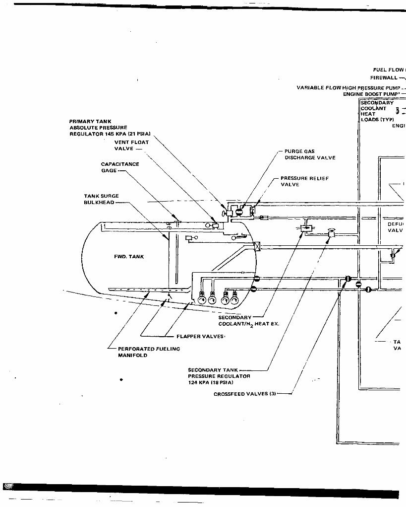
FUEL FLOW I FIREWALL-
VARIABLE FLOW HJGHPRESSURE PUMP - - ENGINE BOOST PUMP”
PRIMARY TANK ABSOLUTE PRESSURE REGULATOR 145 KPA (21 PSIA)
LOADS (TYP) ENGl
VENT FLOAT
,- PURGE GAS DISCHARGE VALVE
CAPACITANCE
PRESSURE RELIEF
BULKHEAD
FWD. TANK
PERFORATED FUELING MANIFOLD / /
SECONDARY TANK PRESSURE REGULATOR 124 KPA 118 PSIA)
CROSSFEED VALVES (3) I’
VA
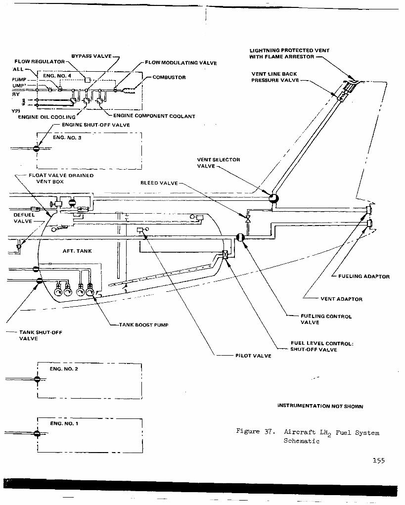
LIGHTNING PROTECTED VENT WITH FLAME ARRESTOR
FLOW REGULATOR FLOW MODULATING VALVE
VENT LINE BACK PRESSURE VALVE -
"._ ENGINE OIL COOLING ENGINE COMPONENT COOLANT
- ENGINE SHUT-OFF VALVE
FLOAT VALVE DRAINED
AFT. TANK
/
- TANK SHUT-OFF VALVE
I" I ENG.N0.2 " 1
====+=
L N i . , O . 1 " 1
\ \ \ VALVE
FUEL LEVEL CONTROL: SHUT-OFF VALVE
PILOT VALVE
INSTRUMENTATION NOT SHOWN
Figure 37. Aircraft LH2 Fuel System S chemat i c
155

. : ,
C .
d.
e .
f .
g .
be adapted t o t h e LH2 t ranspor t , bu t has a l so deve loped suf f ic ien t evidence t o suggest t h a t a l t e r n a t i v e approaches t o t h e ground seg- ment of operat ions m a y be preferable . What i s suggested here i s a wide open study of alternate systems f o r ground operations, not simply further adaptations. Our current a i r terminals evolved from t h e r a i l r o a d s t a t i o n . A study t o i n v e s t i g a t e new logical concepts of a i r te rmina ls des igned spec i f ica l ly for use o f LH2 fuel, without. constraint of modif'ying ex i s t ing f ac i l i t i e s , shou ld p roduce i n t e re s t - i n g results which w i l l be useful as goals for a t ta inment .
Transporter air terminal operat ion. - Inves t iga t e t he poss ib l e cos t savings which mtght be real ized by reduct ion of hydrogen lo s ses
- ~~
using the "shared gate" f 'ueling approach rather than the "leased gate" approach. This would app ly pa r t i cu la r ly t o t he " t r anspor t e r " air terminal systems.
LH2 a i r p o r t power generation study. - An a i rpo r t power systems study of t h e f e a s i b i l i t y o f g e n e r a t i n g power on - s i t e fo r d i r ec t ly d r iv ing -
t he l i que fac t ion equipment ra ther than through use of e lectr ic power. The s tudy should cons ider to ta l a i rpor t and fuel system energy requirements and the optimization of the supply systems, con- s i d e r i n g t h e a i r p o r t as an independent enti ty.
- GSE & ramp operat ions analysis . - A deta i led s tudy of ramp manage- ment problems and so lu t ions fo r t he p ro to type a i r c ra f t i s recom- mended. The study would involve def in i t ion o f the GSE envelopes p r i o r t o docking and t h e i r movements during the ground segment, f i xed apron service connect points, new mobile equipment for cabin and ga l l ey s e rv i ces , and r e l a t ed pos i t i on ing and operat ional implicat ions. It would def ine operat ions which could be performed simultaneously with the fuel ing process .
Hazards analysis. - An analysis of hazards involved in a i r terminal ground operations , including s tudy of r i sk l eve l s a s soc ia t ed w i th kerosene and avgas operations would be performed and acceptable t a r g e t r i s k l e v e l s f o r LH2 operat ions would be explored. This would be a first s tep in determining what concurrent act ivi ty could be conducted during fuel transfer operat ions and t h e r e s u l t s might in f luence fu ture vehic le and airport design exercises .
Bui lding design for safety. - An analysis of a i rcraf t maintenance base building requirements, hangar and shop safety requirements, e tc . This s tudy should include the ent i re range of a i rport bui lding regula tory impl ica t ions re la ted to the use o f the new fuel, e.g., code and underwri ter impacts affect ing publ ic occupancy bui ld ings . It would he lp reso lve the ques t ion of what operations might be per- formed i n a maintenance dock with LH2 f u e l e d a i r c r a f t .
1

, I ,
Para/ortho hydrogen production. - The cos t o f LH2 product ion can be minimized by optimum se lec t ion of para /or tho conten t for tha t LH2 which i s t o be used immediately vs t h a t which i s t o be s tored . The present study assumed 60 percent para conversion for LH2 t o b e u s e d within 2 or 3 days and 97 pe rcen t pa ra fo r t ha t LH2 which might be .I .
s t o r e d f o r several weeks. The proposed study would consider airport use schedules, LH2 production and storage capacity, and determine an optimum schedule for para/ortho production t o minimize costs.
h .
i.
j .
k.
1.
m .
LH2 reservoi r p ressur iza t ion sys tem. - I n v e s t i g a t e l i q u i d hydrogen reservoi r p ressur iza t ion sys tem to reduce vapor iza t ion losses . Present system uses l iquid hydrogen that has been vaporized and r e t u r n e d t o t h e t o p of t he r e se rvo i r . With very l a rge reservoi rs t he l o s ses a s soc ia t ed w i th t h i s sys t em become s i g n i f i c a n t . Alter- nate systems can be developed and evaluated.
LH2 v a p o r i z a t i o n i n a i r c r a f t . - Some information i s known concerning l i q u i d hydrogen vaporization losses in trailers and t ank ca r s t ha t are in motion. However, e s sen t i a l ly no th ing i s known about t h e l iqu id hydrogen vapor iza t ion losses whi le the a i rc raf t i s i n f l i g h t . This i s an area that warrants s tudy - possibly experimental work would be required.
LH2 quant i ty measure. - A system needs t o be developed t o a c c u r a t e l y meter or gage t h e amount of fuel d e l i v e r e d t o t h e a i r c r a f t . P o s s i b l y one t h a t w i l l permit rapid f i l l f o r t h e b u l k o f t h e d e l i v e r y and topping of f the t ank at a slower rat e .
I ,.
LH2 ground supply pumps. - The development o f large, e f f i c i e n t l i q u i d ' :.,, hydrogen pumps f o r t h e ground supply system must be considered. Long l i f e and r e l i a b i l i t y a r e v i t a l c h a r a c t e r i s t i c s .
Recovery of GH?. - Hydrogen flash-off has been determined t o have high economic value. Various methods have been proposed for i t s recovery. No systems such as these have been developed. There are several items t h a t w i l l require development attention. The need for .
repur i f ica t ion of the re turn hydrogen vent gas should be eva lua ted . .;i.
The development of cold gas holders and cold compressors are o f m a j or concern.
1.1 , ,
? . > ' . 2 .
, .
7. CONCLUSIONS
As a resu l t of this prel iminary assessment it was concluded that it i s r e l y feasible and p r a c t i c a b l e t o p r o v i d e f a c i l i t i e s and equipment at Francisco Internat ional Airport (SFO) t o accommodate LH2-f'ueled, long- , commercial t r a n s p o r t a i r t r a f f i c s t a r t i n g i n 1995.
I n i t i a t i o n o f use of LH2 f u e l i n commercial a i r l i n e s e r v i c e i n 1995 was licated on pronouncement of a na t iona l commitment t o t h a t end i n 1980. . ,
:lopment and i n s t a l l a t i o n of a i r p o r t f a c i l i t i e s i s not the pacing item , - . I ,' I

i n t h i s s chedu le . It appears that development of a c a p a b i l i t y t o provide appropriate quantities of gaseous hydrogen by coal gasif ic 'a t ion, and/or e lec t ro lys i s o f water, will be the crucial e lement . For purposes of this study, 2000 A . D . was used as a da te fo r s tudy ing t he fue l and t r a f f i c h a n d l i n g .requirements of SFO, al lowing f ive years after i n i t i a t i o n of service with LH2 f o r - i t s use t o b u i l d t o s i g n i f i c a n t l e v e l s .
. 8 .
The preferred arrangement of l iquid hydrogen facil i ty for SF0 involves piping GH2 f e e d s t o c k d i r e c t l y t o t h e a i r p o r t ; b u i l d i n g a l i que fac t ion and s torage complex on a v a i l a b l e , c u r r e n t l y unused land within a i rport boundaries - (however, the requi red 254,000 m2 of land must be supplemented by reclaiming approximately 81,000 m2 from the seaplane harbor) ; and piping LH2 through a vacuum jacke ted p ipe l ine i n a closed loop around the terminal area t o pro- vide means f o r f u e l i n g a i r c r a f t at conventional gate posit ions.
It w a s concluded that LH2 a i r c ra f t cou ld r e fue l at convent ional gate posit ions, using essentially conventional ground support equipment, in nomi- na l ly t he same elapsed time as c u r r e n t J e t A fue led a i rc raf t o f equiva len t capac i ty . Except ions to th i s s ta tement a re tha t 1) LH2 fue l ing is accom- p l i shed at t h e t a i l cone which i s 10m ( 3 3 f t ) i n t h e air and would requi re a spec ia l f 'ue le r vehic le , and 2 ) t h e f l i g h t crew must be provided a separa te access t o t h e f l i g h t s t a t i o n s i n c e t h e r e i s no passageway between t h e pas- senger compartment' and the cockpit i n the subjec t a i rc raf t . Nine teen of the 81 ga te pos i t ions p lanned for SF0 subsequent t o 1985 can accommodate t h e long range t ra f f ic assumed f o r t h e LH2 a i r c r a f t .
Five spherical s torage vessels , each 71 f ee t i n ou t s ide d i ame te r , w i l l contain a t o t a l of 18,925 m3 of LH2. The s torage t anks w i l l be in su la t ed by 0.76 m of perl i te in an evacuated annulus surrounding the LH2 container . The ne t evapora t ion ra te from these t anks i s conservat ively es t imated to be 0.06 percent of tank contents per day with 13 Pa (100 microns) pressure in the annulus . However, experience with tanks of similar design at Cape Kennedy have demonstrated boiloff rates of only 0.02 % per d a y s o somewhat lower loss rates than theory ind ica tes may be expected.
It i s e s t ima ted t ha t t he p l an t and equipment r equ i r ed t o p rov ide LH2 capab i l i t y a t SF0 will amount t o $340.4 m i l l i o n i n 1975 dol lars . This does not include any considerat ion of the investment required for the supply of e i t h e r gaseous hydrogen feedstock, or for electric power. According t o t h e ground rules .of the s tudy , bo th of these items were assumed t o be ava i lab le and t h e c o s t s were inc luded in the ra te pa id for the gas and e l e c t r i c power.
Sane of the more specif ic conclusions which were reached during this s tudy are the fol lowing:
0 The pro jec ted maximum requirement for LH2 at SF0 i n 2000 A . D . i s 7.68 kg/s (731.4 t ons /day ) de l ive red t o t he a i r c ra f t eng ines . Th i s i s for the average day i n t he peak month.

0
0
0
0
0
0
0
The s e l e c t e d LH2 supply and a i rc raf t fue l ing system involves boi loff l o s ses amounting t o 15.7 percent . Of t h i s t o t a l , 91.5 percent i s recoverable and can be r e l ique f i ed . Only 1.34 percent of t h e t o t a l LH2 manufactured i s l o s t . That ‘ is t h e q u a n t i t y v e n t e d i n f l i g h t , o r dur ing opera t ion of the a i rc raf t on t h e ground.
It i s economically preferred t o pipe GH2 t o t h e a i r p o r t and l o c a t e the l i que fac t ion p l an t on s i t e . If the l iquefact ion plant cannot be located on t h e a i r p o r t , LH2 can be moved most economically by vacum j acke ted p ipe l ine fo r d i s t ances up t o about 40 miles. For greater d i s t ances , r a i l road t ank ca r i s the p re fe r r ed means of t rans- por t . If ra i l road tank cars must be used f o r any reason, it i s most advantageous to l o c a t e t h e l i q u e f a c t i o n p l a n t at t h e GH2 source and move t h e LH2 the ent i re d is tance t o t h e a i r p o r t .
The t r anspor t e r sys t em fo r hand l ing a i r c ra f t l oad ing and unloading appears t o o f f e r i n t e r e s t i n g p o t e n t i a l f o r many a i r p o r t s . It w a s n o t s u i t e d t o SF0 and w a s n o t e x m i n e d i n d e t a i l .
The shared gate approach has the potential of minimizing both c a p i t a l and opera t ing cos ts .
The externa l t ank a i rc raf t des ign concept i s c o n s i d e r e d i n f e r i o r t o t he i n t e rna l t ank ve r s ion i n terms of refueling procedure, passenger acceptance, and ground operations in general.
Use of a pump-fed system, ra ther than a pressure system, was s i g n i - f icant ly advantageous for moving LH2 from the a i rpor t s torage t anks t o t h e a i r c r a f t t a n k s . S i m i l a r l y , t h e p r e f e r r e d a i r p o r t f u e l t ransfer sys tem i s a loop arrangement which empties from one storage tank in to another a f te r be ing c i rcu la ted pas t a l l of t h e gate pos i t ions . This assures immediate ava i l ab i l i t y o f LH2 t o any gate with no c h i l l down required.
A d e f u e l / r e f i e l a r e a was provided near the LH2 s torage t anks s o a i r c r a f t which a r e t o be out-of-service for extended periods, or which r e q u i r e i n s p e c t i o n o r r e p a i r o f t h e i r f u e l t a n k s , can be e f f ic ien t ly p rocessed .
Consideration of the cycle t ime required t o d e f u e l , warm-up, and i n e r t LH2 a i r c r a f t tanks before inspec t ion and/or repa i r o f t ank components can be performed, i n add i t ion t o t he co r re spond ing time requ i r ed t o pu rge , pu r i fy , and r e f u e l , means t h a t LH2 tank and associated fuel system components must be developed t o a high degree of r e l i a b i l i t y b e f o r e b e i n g p u t i n s e r v i c e .
The pro jec ted SF0 LH2 l i q u e f a c t i o n f a c i l i t y would require approxi- mately 332 MW of e l e c t r i c power. There i s much t h a t can be done t o minimize the requirement for purchased power and fu r the r s tud ie s are recommended.
160

0 Cost of LH2 d e l i v e r e d t o t h e a i r c r a f t usin t h e SF0 f a c i l i t y i s c a l c u l a t e d t o b e 894/kg (404/lb = $7.81/10 Btu) based on GH2 feedstock at 364/kg (16.54/lb) and e l e c t r i c p a r e r at 24/kWh.
8. RECOMMENDATIONS
I n view of the need t o develop an a l t e r n a t e for petroleum-based J e t A type f u e l i n t h e f o r s e e a b l e f u t u r e , and because LH2 has been shown t o b e a most a t t r ac t ive cand ida te , it i s recommended t h a t a comprehensive development program be actively pursued.
Numerous suggestions have been presented in Section 6 which o u t l i n e worthwhile technology development and study items p e r t i n e n t t o a i r p o r t f a c i l i t i e s and equipment. O f these , the fo l lowing are recommended f o r i m - mediate implementation :
0 LH2 use i n i t i a t ion s tudy
Model a i r terminal design
0 Transporter air terminal operat ion
0 LH2 a i r p o r t power generation study
0 GSE and ramp operat ions analysis , in combinat ion with a hazards ana lys i s .
0 Bui ld ing des ign for sa fe ty .
In addi t ion , a s o c i e t a l impact study i s recommended t o provide an assess- ment of the effect conversion of the air t r a n s p o r t i n d u s t r y t o LH2 f u e l would have on s o c i e t y i n g e n e r a l . I n t h i s s t u d y a h y p o t h e t i c a l b u t r e a l i s t i c s c e n a r i o d e p i c t i n g t h e t r a n s i t i o n t o hydrogen would be developed, and t h e economic r a m i f i c a t i o n s , t h e i n s t i t u t i o n a l b a r r i e r s and incen t ives , and t h e soc ia l d i s loca t ions and oppor tuni t ies of a l l major s takeholder c lasses in soc ie ty would be disclosed. Stakeholder c lasses whose pa r t i ' c ipa t l i on i n t he evolut ionary scenario would be descr ibed include the fol lowing:
a i r l i n e s
a i rcraf t manufacturers
fue l supp l i e r s
a i rpor t opera tors
consumers
government r egu la to r s
161

This study would provide important input and an order of priorities for the t echn ica l work. I n a d d i t i o n it would acquaint, and hopef'ully convince, many stakeholders of the need for early conversion of c o m e r c i a l a v i a t i o n t o hydrogen f'uel.
162

APPENDIX A
HYDROGEN SUPPLY METHODS
This appended material is a de ta i led p resenta t ion of the ca lcu la t ion of r e fue l ing l o s ses . It i s based on a preliminary estimate o f the design of the fue l ing sys tem for the purpose o f de te rmining the to ta l quant i ty o f LH2 t o be supplied and transported so t h a t Task 3 studies could be conducted. Differ- ences exist between the configurat ion of the fuel ing c i rcui t assumed here in and the conf igura t ion f ina l ly adopted in Task 7; spec i f ica t ions for the sys tem assumed here are presented.
Al. CALCULATION OF LIQUID HYDROGEN RFFUEL RFQUIRED VS NET FUEL TO ENGINES
Table 1 shows r e fue l ing ca l cu la t ion results for th ree d i f fe ren t miss ions .
0 Sample Mission - Se lec t ed t o g ive two missions per day average a t a n a i r c r a f t u t i l i z a t i o n o f 4000 h r / y r .
0 Design Mission - Based on 23 995 kg (52 900 lb) block fuel weight
0 Contingency Mission - Based on completely fu l l tank a t t akeof f . Block fuel weight i s 27 941 kg (61 600 lb)
The Sample Mission i s very c lose to the typ ica l o r average miss ion from Task 2. Using t h e Sample Mission as an example, the source of the various fue l l o s ses w i l l be explained i n d e t a i l . The f l i gh t du ra t ion o f the Sample Mission w i l l be 5.5 h r and , a t a 4000 h r /y r u t i l i za t ion r a t e t he non-u t i l i zed o r ground time will be 6.5 h r t o g i v e a t o t a l time per mission o f 12 hr . The bo i lo f f loss due t o h e a t l e a k i n t o t h e a i r c r a f t f u e l t a n k w h i l e i n f l i g h t amounts t o 455.0 kg (1003 l b ) . Ground-time hea t l eak loss w i l l be 665 .O kg. (1466 l b ) . The uni t bo i l -of f ra tes o f 1 .379 and 1.705 kg/min (3.04 and 3.75 lb/min) were mutually agreed upon by Lockheed and Linde . Net engine fuel requi rements for the f l igh t amount t o 11 340 kg (25 000 lb) and t h i s m u s t , o f course, be loaded into the tank. While i n f l i g h t , some o f t h e L% must be vaporized for displacement of the fuel which has been consumed. For t h i s mission, 302 kg (665 l b ) are requ i r ed bu t t h i s is less than the 455 kg (1003 l b ) loss due t o hea t l eak so no addi t iona l loss i s incurred f rom this cause. The d i f f e rence , 140 kg (338 l b ) , must be vented f rom the a i rc raf t while i n f l i g h t . Total l iquid required during the mission is the re fo re t he SUm Of t h e n e t fuel t o the engines and the f l igh t time b o i l - o f f o r 11 795 kg (26 003 l b ) .

TABLE 1. CALCULATION OF LIQUID HYDROGEN REFUEL REQUIRED VS. NET FUEL TO ENGINES
nission tin Nonutiltzed time (average) Total tin allocated t o mission
(Avg. u t i l i z a t i o n - 4000 h r / h r )
Tank heat leak boil-off During mission ti* (3.04 lb/nin) During nonutilized time (3.76 lb/mln) Total
Net fuel to engines b i l -o f f r equ i r ed for displacemcnt
Remainder of mission boil-off E x t r a vl.porizstion for displacemcnt Hotion losses Total liquid required during miasion
Boil-off during nonutilized the Refueling pump vork
Total liquid per mission Refueling system losses
Loss saved by v d n g liqutd Net liquid per mlssion
Total losp per a lss ion
net loss per mlssion after warning l i q u i d
Expected average % l o s s
Venting during refuel(s )
of net fu~l (2.66%)
Displncement Heat leak boil-off during refuel Piping system loss Pump vo* Saved by vsrning l iquid
Total from cold supply tank Total fro= wum supply tank
.Estimated f r o m other da ta in Task 2 rewrt
Units - Customary
hr hr
l b l b l b
l b l b
l b l b l b l b
lb l b l b l b l b l b
l b
l b %
z %
l b l b l b l b l b l b l b
Sample Mission
SI
6.5 5.5
12 .o
665 455
1 120
11 340 302
15 3 0 0
11 795
665 81
305 12 8k5
-252 12 593
1 505
1 254 13.3
11.1 12.2
3 31 65
187 81
-252 412 664
Design Mission SI
11.7 13.8 25- 5
968 1 ,412 2 380
23 995 6 38
329 0 0
24 963
1 412
305 169
26 849 -415
26 434
2 854
2 439 11.9
10.2 11.0
702
187 65
169 -415
708 1 123
Contingency Mission
SI
.13.88
30.28 16.b
1 149
2 827
27 9bl 74 3
405 0 0
29 090
1 678
1 678 198
*.610 **31 576
.*30 957 -619
3 635
3 015 13.0
10.8 11.9
818 130 374 198
-619 901
1 520
Customary
e(13.88)
(30.28) (16.b)

TABLE 1. (continued)
Venting during maximum refue l
Displacement f o r 29 090 kg (64 132 pounds). of l i q u i d
Tank Heat Leak 38 minutes Transient Piping 38 minutes Staycold piping portion for 38 minutes Pump Work
Subtotal
Potential Saving in Loss by Warming Liquid (-12841 Actual Savings
Net Subtotal
Total venting
Avg. vent rate per second from supply tank
Liquid pumped during maximum re fue l
Net l i q u i d On board Losses Average pumping rate per second
m3/s P cn VI
mm
I
First Refueling From Cold
Supply Tank
S I kg
774
6 5
-mT 188
-444
150 4 1
0
774
0.34
29 090 0
12.76 0.1803
Last Refueling From Warm
Supply Tank
SI kg
774
65 150
4 1 188 444
0
- 444
1 218
0.535
29 090 444
12.95 0.1830

This i s n o t t h e t o t a l LH2 r e q u i r e d f o r f u e l i n g t h e a i r c r a f t , however. There is a 665 .O kg (1466 l b ) bo i l -o f f due to hea t l eak du r ing ground time plus a 80.7 kg (178 l b ) loss due t o energy imparted t o t h e L+ by t h e r e f u e l pumps and a 305 kg (672 lb ) r e fue l ing sys t em loss. The la t ter loss is d e t a i l e d i n Table 4 and will be subsequently discussed. "he sum o f t h e s e l o s s e s , 1050.5 kg (2316 l b ) , i s t h e t o t a l ground time loss which when added t o t h e total mission requirements of 11 795 kg (26 003 l b ) result i n t h e o v e r a l l l iquid requirements of 1 2 845 kg (28 319 l b ) .
The overal l l iquid requirements may ac tua l ly be somewhat less than the preceding quant i ty , which is based on LH2 at sa tura t ion condi t ion as it e n t e r s t h e a i r c r a f t f u e l t a n k . However, t h e first s e v e r a l a i r c r a f t r e f u e l e d from a full supply tank w i l l r ece ive subcooled l iqu id ins tead of sa tura ted l iqu id , giving some opportuni ty to "save" some los ses by warming t h e l i q u i d r a t h e r t h a n boi l ing it. With fu l l subcool ing in the LH2 supply tank based on a 103.4 kPa (15 p s i a ) p re s su re and with 114.8 kPa ( 2 1 p s i a ) i n t h e a i r c r a f t t a n k , l o s s e s w i l l be reduced by 252 kg (555 l b ) , giving a ne t l iqu id per miss ion of 12 593 kg (27 764 l b ) . With warm l i q u i d i n the s torage t ank , t o t a l l o s s e s based on 11 340 kg (25 000 lb) ne t fue l t o eng ines amount to 13 .3% and with fu l ly subcooled l iqu id they a re 11.1%. Actual operation i s probably repre- sented by some intermediate condi t ion as represented by the ari thmetic average value of 12.2%.
The next portion of Table 1, presents the var ious sources of vent gas given off dur ing refuel ing. There are 331 kg (731 l b ) of vapor displaced by the 11 795 + 665 kg (26 003 + 1466 l b ) o f l i q u i d which en te r s t he fue l t ank , plus 64.9 kg (143 lb) of vapor result ing from hea t l eak dur ing the 38-min refuel ing per iod and 80.7 kg (178 lb ) o f vapor r e su l t i ng from pump work. The t o t a l can be reduced by 251.7 kg (555 l b ) i f fue l ing was done with subcooled l i qu id . The t o t a l v e n t r a t e amounts to 412 .3 kg (909 lb ) if fue l ing from a cold supply tank and 664.0 kg (1464 l b ) i f fue l ing from a warm supply tank.
Table 1 a l so shows calculat ion of vent ing and pumping r a t e s f o r a m a x i m u m refuel involving 29,090 kg (64,132 l b ) of LH2 loaded in to the fue l t anks i n 38 minutes. Calculations are presented for both cold and warm supply tanks. In the case of the cold supply tank, there i s more than su f f i c i en t r e f r ige ra - t i o n i n t h e s u b c o o l e d l i q u i d t o overcome tank heat leak, p iping. losses and pump work so that the only vapor vented i s t h e 773.8 kg (1706 l b ) r e s u l t i n g from displacement. In the case of the w a r m supply tank, these add i t iona l losses add to the displacement vapor to produce a t o t a l v e n t i n g rate of 1,218 kg (2685 l b ) . Over t h e 38 minute refuel ing per iod, the average vent r a t e s are 0.34 kg/s (0.75 lb/sec) and 0.535 kg/s (1.18 lb / sec ) r e spec t ive ly . Pumping r a t e from a warm supply tank, based on a t o t a l l i q u i d q u a n t i t y o f 29 534 kg (65 111 1b) , i s 0.1830 m3/s (2,901 g p m ) .
166

A2. ESTIMATION OP SUPPLY TANK PRESSURIZATION LOSSES
Table 2 shows c a l c u l a t i o n o f l o s s e s i n a l a r g e ground storage tank, These los ses are a s t rong func t ion of the manner i n which the t ank is used, ranging from a bes t case o f 3.16% t o 52.7%. The primary source of loss is the displacement vapor required e i ther to provide NPSH f o r t h e r e f u e l i n g pumps or provide AP for the re fue l ing p ip ing wi thout a pump. This displacement vapor is obta ined by vapor iz ing , ex te rna l to the t ank , a p o r t i o n o f t h e l i q u i d i n s t o r a g e . The lowest possible loss is f o r an ideal operat ion which starts with a full cold t ank and severa l a i rc raf t are re fue led by pumps i n a shor t time u n t i l t h e t a n k i s empty. Refueling would then switch t o a n o t h e r fu l l cold tank. The l i q u e f i e r would make i n t o (or vehic le would unload i n t o ) t h e tank(s ) whi le they a re no t be ing used for re fue l ing . The h ighes t loss is f o r in f requent re fue l ing of ind iv idua l a i rc raf t , requi r ing the t ank to be blown down and repressurized each time. For a well-designed ground tank, heat leak i s a very s m a l l p a r t o f t h e t o t a l loss. Prdssure t ransfer for the es t imated piping system gives a very high loss. If p res su re t r ans fe r were actual ly used, all the p ipe s i z e s should be increased to reduce tank losses ( a t the expense of increased p ip ing sys tem losses) .
A bas i c problem i s the need for subcooled l iquid for several purposes ,
0 To provide pump NPSH,
0 To maintain single phase flow i n piping,
To achieve minimum f lashoff whi le re fue l ing a i rc raf t .
To accomplish these objectives it i s necessa ry t o f l a sh t he l i que f i e r make t o as low a pressure as p r a c t i c a l t o g e t it as cold as possible . (103 kPa (15 p s i a ) assumed fo r t hese ca l cu la t ions . ) If t h e l i q u e f i e r m a k e is s e n t t o a tank a t e levated pressure , it can not be cooled to sa tura t ion a t 103 kPa (15 p s i a ) and the needed subcooling w i l l not be avai lable . For these reasons it i s necessary to make i n t o a d i f f e ren t t ank t han t he one being used for refuel ing.
To obtain subcooling for whatever purpose, S t is necessa ry t o ob ta in a non-equilibrium gas phase pressure higher than the saturation pressure of the l iqu id . (34 .5 kPa ( 5 p s i ) pump NPSH used for these ca lcu la t ions . ) Whenever the gas phase i s a t higher pressure (warmer) than t he s a tu ra t ion p res su re o f t he l i qu id , it c a u s e s t h e l i q u i d t o w a r m up , first at t h e s u r f a c e , and over a per iod of t ime , t h e en t i re mass o f l i q u i d w a r m s t o a new equ i l ib - rium. If the t ime of exposure to the non-equilibrium gas is kept very short , t h e warming of the l iqu id can be kept small. Under these condi t ions , much of t he l i qu id can be removed "cold." When t h e l a y e r o f w a r m l iqu id reaches t ank bot tom, the to ta l p ressure must be increased to maintain subcool ing for i t s removal. In these ca lcu la t ions , 172 kPa (25 ps ia ) p ressure was assumed f o r removal of 138 kPa (20 p s i a ) s a t u r a t e d l i q u i d d u r i n g fast removal. When t h e l i q u i d i s removed slowly, the gas phase pressure must be cont inua l ly increased as warmer l i q u i d is removed. The increased pressure causes increased warming

TABLE 2. ESTIMATE OF SUPPLY TAM( PRESSURIZATION LOSSES
Tank capacity Pump HPSH Starting pressure full tank Pressurization to start pmping
Operating Method X 1 - Quickly reiuel several a i rc raf t until tank is empty
Saturation pressure .in tank at end Total pressure for NPSH Displacement at 172.4 kPa (25 ps ia ) 3.156%
Operating Method 12 - Refuel aircraft one at a time
Firs t re tuc l ing f r o m full tank Displacement at 137.9 kPa (20 p s i a ) 2.527%
Last refueling to empty the tank L% Pumped
Pressurize remainder of tank f r o m 103.4 t o 137.9 kPa
Remining'displacelrnt for l iquid converted to
Total pressurizing l iquid to gas
Displacemcnt e 137.9 kPA 2.527%
261 377 kg portion e (2.527% - 1.922%)
pressurizing gas (1.922%)
Aver- of first and last Loss % (share each refueling)
Operating h t h o d 13 - Pressure transfer Liquid muld get too hot to allow ncthod similar to #I. merefore, t d is blown down between refuelings similar t o #2.
Firat Rehel ing from full tank
L a s t m a l i n g 60 empty the tsak Maplace=nt at 3 4 . 1 kPa (44.1 psia)
Llt t ransferred Digpllacelrnt e 3 4 . 1 kPa 5.719% Pressurize reminder 103.4 - 304.1 kPa (5.719 - 1.922) Remaining displacemcnt for l iqu id to p ressur iz ing gas Total pressurizing l iquid to gas
Average of F i r s t and Last Loss
272,154 kg (600 000 l b ) 34.5 kPa (5 M i )
103.4 kPa (15 psia) 137.9 kPa (20 p s i s )
137.9 kPa 120 p a i d 172.4 kPa ' (25 ps ia ) 8 589 kg (18 936 l b )
3.156%
272.3 kg (600.4 l b )
10.776.8 kg (23 759 l b ) 272.3 kg (600.4 l b )
1 581.4 kg (3 486.3 l b )
2.527%
36.3 kg (80.1 l b ) 1 890.0 kg ( 4 166.8 l b )
17.538% 10.032%
5.719%
10 776.8 kg 616.3 kg
9 924.5 kg 206.5 kg
10 747.3 kg 99.726% 52.722%
If pressure t ransfer actual ly were used, probably would increase a l l pipe s izes to get lower pressure drop. A t 202.7 kPa, the average of f i r s t and last loss would be 26.255%. This would require a 50% increase in a l l pipe diameters and approxi- mately a 50% increase i n piping system losses. If a l l pipe diameters uere increased by a factor of 2.5 times, tank pressurizing losses would be the same as for the two pump operating methods. but without any pumps. Piping system losses would increase about 2.2 times.

of the remaining l iquid. Because of this problem, it would not. be p o s s i b l e t o maintain l iquid subcooled below the 145 kPa (21 p s i a ) relief va lve s e t t i ng o f t he a i r c ra f t t ank , fo r s low con t inuous removal o f t he l i qu id . Fo r t h i s reason, if t h e r e are not enough a i r c r a f t t o be refueled to quickly empty. a tank, it w i l l be necessary t o blow the t ank down t o r e - e s t a b l i s h c o l d l i q u i d .
To eva lua te t he e f f ec t o f t he above problem, calculations were made f o r three different tank operat ing methods.
0 vethod No. 1 - Quick removal by pump o f all l i q u i d s t a r t i n g w i t h a full tank at 103 kPa (15 psia) and ending with an empty tank at 172 kPa (25 ps ia ) . The last drop of l i q u i d removed is subcooled at 138 .kPa (20 p s i a ) . This is t h e most ideal possible operat ion and gives a 3.2% loss.
0 Method No. 2 - Ind iv idua l r e fue l ing o f a i r c ra f i by pump over an extended period of time. The tank i s p res su r i zed t o 138 kPa (20 ps ia ) for each refuel ing and blown down t o 1 0 3 kPa (15 p s i a ) between ref'uelings. Losses amount t o 10.0% based on averaging i n i t i a l and f i n a l r e f u e l l o s s e s .
Actual operations using pumps would probably be a combination of Methods 1 and 2 , g iv ing losses somewhere between.
0 Method No. 3 - Pressure t ransfer re fue l ing or re fue l ing wi thout pumps, Operation is similar t o Method No. 2 i n t h a t t h e t a n k is blown down a f t e r each r e fue l ing . To maintain single phase flow i n the piping without using pumps, the non-equilibrium pressure 'must be high enough to p rov ide all the piping pressure drop. Assuming t h e same piping system that was used when pumping LH2, t h i s p re s su re is about 203 kPa (29 .4 ps i ) which is high enough t o c a u s e t h e l i q u i d t o warm faster and t o a higher temperature . Saturat ion pressure below 145 kPa (21 p s i a ) can not be maintained for continuous operation, no matter how fast , For this reason, only the one-at-a-time operation was ca lcu la ted . The tank is p res su r i zed t o 304 kPa (44.1 p s i a ) f o r each refueling, and blown down t o 1 0 3 kPa (15 psia) between. This gives losses of 52.7%.
Obviously, larger piping would requi re less pressure drop, less gas phase pressure, and lower tank loss, at the expense of higher piping system los ses and c a p i t a l c o s t . "hough no fu r the r ca l cu la t ions were made, t h e following estimates were made : A .SO% inc rease i n p ipe s i ze s would reduce gas phase pressure t o 202.7 kPa ( 2 a t m ) and losses to 26.3%. A 250% i n c r e a s e i n p i p e s i z e t o 5 0 . 8 cm and 101.6 cm vs 20.3 cm and 40.6 cm (20 in. and 40 i n . vs 8 i n . and 16 i n . ) would get pressures and t a n k l o s s e s i n t o t h e same magni- tude as with pumps. There would be a pressure transfer opt imizat ion among p i p e s i z e , t a n k s i z e , e t c . , for . spec i f ic re fue l ing schedules . No optimized pressure t ransfer Calcu la t ions were made, pr imari ly because the pump transfer opera t ion of fe rs lower loss.
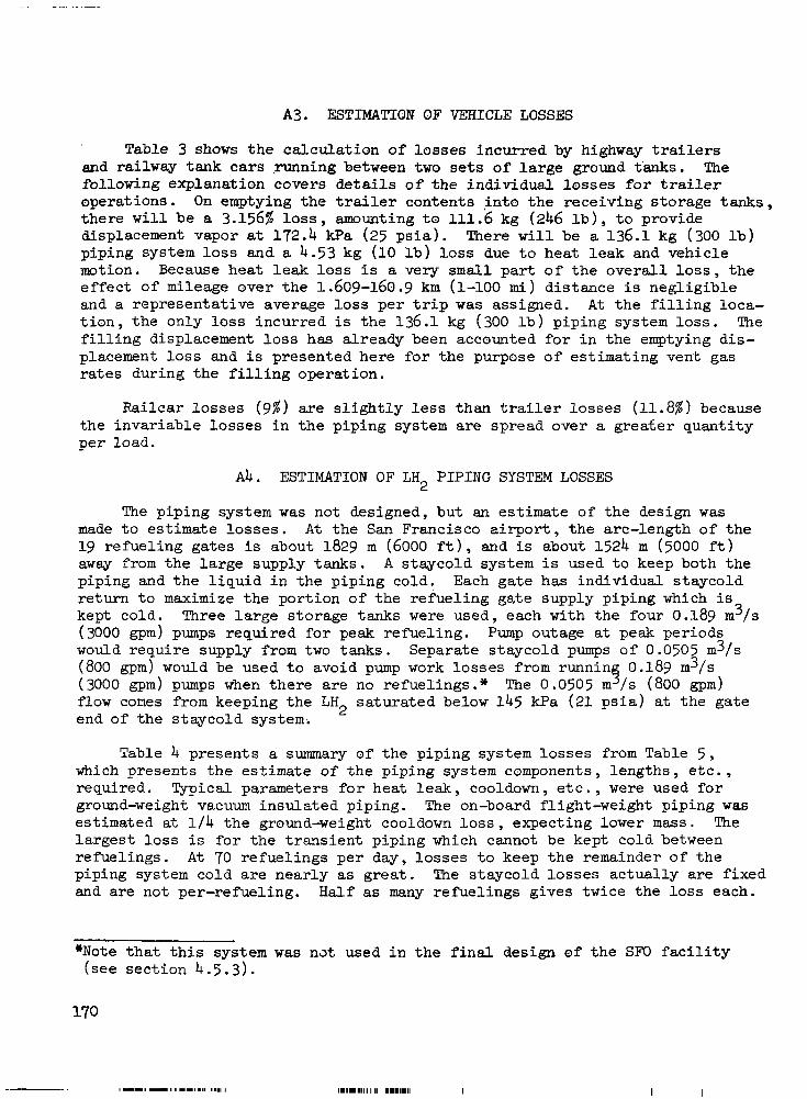
A3. ESTIMATION OF VEHICLE LOSSES
Table 3 shows the ca l cu la t ion o f l o s ses i ncu r red by highway trailers and railway tank cars running between two sets of large ground t 'anks. The fol lowing explanat ion covers detai ls of the individual losses for trailer operat ions. On emptying the t ra i ler contents , in to the receiving s torage tanks, t he re w i l l be a 3.156% l o s s , amounting t o 111.6 kg (246 l b ) , to p rovide displacement vapor a t 172.4 kPa (25 p s i a ) . There w i l l be a 136.1 kg (300 l b ) piping system loss and a 4.53 kg (10 l b ) loss due t o h e a t l e a k and vehicle m t i o n . Because heat leak loss i s a very small p a r t o f t h e o v e r a l l l o s s , t h e effect of mileage over the 1.609-160.9 km (1-100 m i ) d i s tance i s negl ig ib le and a representat ive average lo s s p e r t r i p was assigned. A t t h e f i l l i n g l o c a - t i o n , t h e o n l y loss incur red i s t h e 136.1 kg (300 lb) p ip ing sys tem loss . The f i l l ing displacement loss has already been accounted for in the emptying dis- placement loss and is presented here for the purpose of estimating vent gas rates dur ing t he f i l l i ng ope ra t ion .
Ra i l ca r l o s ses (9%) are s l i g h t l y less than trailer lo s ses (11.8%) because the i nva r i ab le l o s ses i n t he p ip ing sys t em are spread over a grea te r quant i ty per load .
Ab. ESTIMATION OF LH2 PIPING SYSTEM LOSSES
The piping system was not designed, but an estimate of the design was made t o e s t i m a t e l o s s e s . A t t h e San Francisco a i rport , the arc- length of the 19 refue l ing ga tes is about 1829 m (6000 f t ) , and is about 1524 m (5000 f t ) away from the l a rge supply t anks . A staycold system is used t o keep both the p ip ing and the l iqu id i n the p ip ing co ld . Each gate has individual s taycold r e t u r n t o maximize the por t ion o f the re fue l ing ga te supply p ip ing which is kept cold. Three large storage tanks were used, each with the four 0.189 m3/s (3000 gpm) pumps required for peak refuel ing. Pump outage a t peak periods would require supply from two tanks. Separate s taycold pumps o f 0.0505 m3/s (800 gpm) would be used to avo id pump work losses from runnin 0.189 m3/s (3000 gpm) pumps when the re a r e no refuel ings." The 0.0505 m 5 / s (800 gpm) flow comes from keeping the LH sa tu ra t ed below 145 kPa (21 p s i a ) a t the ga te end of the staycold system. 2
Table 4 presents a summary of the piping system losses from Table 5 , which presents the estimate of the piping system components , lengths , e tc . , required. Typical parameters for heat leak, cooldown, e t c . , were used for ground-weight vacuum insu la ted p ip ing . The on-board flight-weight piping was estimated at 1 / 4 t h e ground-weight cooldown loss, expecting lower mass. The l a r g e s t loss i s fo r t he t r ans i en t p ip ing which cannot be kept cold between refuel ings. A t 70 refuel ings per day, losses to keep the remainder of the piping system cold are near ly as g r e a t . The s taycold losses ac tua l ly a re f ixed and are not per-refueling. Half as many refuel ings gives twice the loss each.
*Note tha t t h i s sys t em was nat used i n t h e f i n a l design of t h e SF0 f a c i l i t y (see sec t ion 4 .5 .3) .
11111.1111 I I1 111111.11 I I I

TABLE 3. ESTIMATED LOSSES I N VEHICLES .MOVING BETWEEN LARGE TANKS
Nominal capaci ty
Trailer Ra i l ca r
S I Customary S I Customary
3 536 (7 796) 7 581 (16 714)
Emptying losses
Displacement a t 172.4 kPa 112 (246 1 244 (537 1 Heat leak and motion loss a t O.S%/day 17.7 (39 1 38 (84) S h a r e p e r t r i p 4.3 (.lo 38 (84 1 Piping system loss 136 ( 3 0 0 ) 181 (400)
Total, emptying loss 252 (.556 ) 463 (1 021)
Net LH del ivered 2
F i l l i n g
3 284 (7 240) 7 118 (15 693)
Piping system loss 136 (300 ) 181 (400)
Fi l l ing displacement a t 103.4 kPa 68 (150 1 142 (312 T o t a l , f i l l i n g loss 136 (300 1 181 (400)
Gross LH2 t o f i l l 3 672 (8 096 ) 7 763 (17 114 1
Tota l Loss
%
A l l t abu la t ed va lues i n fo l lowing un i t s
SI - kg Customary - lb
Capacity of highway t ra i le r - 49.97 m3 (13 200 g a l )
Capacity of r a i l c a r - 107.13 m3 (28 300 g a l )
, . . . . . -

TABLE 4. LIQUID HYDROGEN PIPING SYSTEM BOIL-OFF
(SI UNITS)
Descr ipt ion
Staycold re turn
Staycold re turn
Staycold supply
St aycol d supply
Total Staycold
@ 70 r e fue l ings pe r day
Transient piping
Pipe Equiv. Size Length Factor Boil-off Boil-off cm m j /s -m g/s kg/Refuel ”
2.54 3902.1 0.0411 3.844 10.16 5430.1 0.109 14.189 20.32 6042.0 0.212 30.670 40.64 5288.0 0.420 53.232
Heat l eak 38 minutes 20.32 251
Cooldown 38 minutes 20.32 47.6
T o t a l t r a n s i e n t
P ip ing bo i l -of f per re fue l ing
@70 per day
Pump work t o run s taycold System (203.4 kPa, 3.03 m3/ min 1
Transient piping port ion on boa rd a i r c ra f t
Heat l eak 38 minutes
Cooldown 38 minutes
170.1 20.0
101.936
125.8
9.0 141.6
150.6
276.4
22.889 23.7
6.1 59.4
65.5 Total
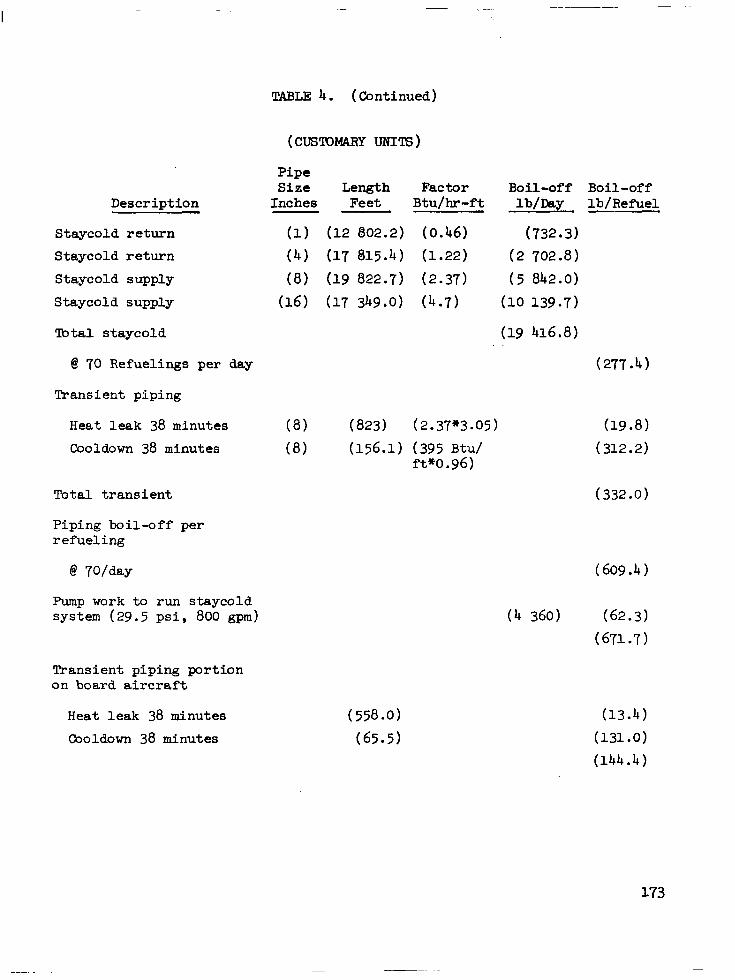
TABLE 4. (Continued)
Description
Staycold re turn Staycold r e t u r n Staycold supply
Staycold supply
%I t a l s taycold
@ 70 Refueling9 per day
Transient piping
Pipe Size Length Factor
Inches Feet Btu/hr-ft
(1) (12 802.2) (0.46)
( 4 ) (17 815.4) (1.22)
(8) (19 822.7) (2.37)
(16) (17 349.0) (4 .7)
Heat l eak 38 minutes (8) (823) (2.37*3.05)
Cooldown 38 minutes (8) (156.1) (395 Btu/ ft*o .96)
Tota l t rans ien t
Piping boi l -off per r e fue l ing
Pump work to run s taycold system (29.5 psi, 800 gpm)
Transient piping port ion on boa rd a i r c ra f t
Heat l eak 38 minutes
Cooldown 38 minutes
Boil-off Boil-off lb/Day lb/Refuel
(732.3)
(2 702.8)
( 5 842.0)
(10 139.7)
(19 416.8)
(277.4)
(332.0)

TABLE 5.
Refueling Pump Piping
Suction 8 i n .
S t r a igh t E l l s Hose Coupling Valve J o i n t s
Discharge 8 i n .
S t r a igh t Ells Hose Coupling Valve Tee
J o i n t s
Priming 8 i n .
S t r a igh t E l l s J o i n t s
Total for Refuel ing Pumps
Common Piping Set of 4 Pumps
S t r a igh t Ells Tees Valve
ESTIMATE OF LOSSES I N LIQUID HYDROGEN PIPING SYSTEM
(12 r e q ' d ) ea
30 f t 2 3 ft 1 1 7
20 ft 3 3 ft 1 2 2
12
100 f t 4 9
(3 r e q ' d ) ea
150 f t 1 2 1
Heat Leak
Length Equiv. Factor Feet
1 3.1 3.1 50 50.6 12.5
1 3.1 3.1
50 50.6 4.6
12.5
1 3.1 12.5
1 3 4 60
J o i n t s 20 12
( f o r 12)
360 74.4 111.6 600 607.2 1050
24 0 111.6 111.6 600 1214.4 110.4
1800
1200
1350 148.8
9690.0
( f o r 3)
450 9 24 180 720
Pressure Drop
Length Equiv. Fact o r Feet
1 30 9.2 18.4 28 84 0 0
112.4 112.4 0 0
1 20 9.2 27.6 28 84 0 0
112.4 ("1) 112.4 10.8 36.8 47.6 0 0
1 (*o> 9.2 0
0 0 0
536.4

Set of 3 Tanks - Common 16 i n .
TABLE 5 (Continued)
Heat Leak
ea
Length Equiv. Factor Feet
S t r a igh t 400 ft 1 Ell 2 3 Tee 1 4 J o i n t s 17 12
Supply Line 16 i n .
S t r a igh t E l l s J o i n t s
D i s t r ibu t ion Header - 16 i n .
S t r a igh t E l l s Valves J o i n t s
5000 f t 1 8 3
141 12
6000 f t 1 20 3 4 50
198 12
Total 16 in . P ip ing
Refuel ing Stat ion 8 i n . (19 Req'd)
Ground Stay Cold 8 i n . ea
S t r a igh t E l l Tee 16 x 8 Valve F i l t e r J o i n t s
Total each To ta l fo r 19
200 f t 4 1 1 1 20
( f o r 1)
400 6 4
2 04
5 000 24
1 692
6 000 60
200 2 376
17 349.
1 200 3.1 12.4 4 4
50 50 16.9 16.9 12.5 250
533.3 10 132.7
Pressure Drop
Length Equiv. Factor Feet
1 15 0
1 9 - 2
36.8 112.4
35 0
200 30 70 0
5000 120 0
3000 1 5 0 500
0
9575
200 36.8 36.8 112.4
35 0
421.0 -

TABLE 5 (Continued)
Heat Leak Pressure Drop
S t a y Cold Return Piping (19 Req'd) a t Refuel ing Stat ion 1 i n . ea
S t r a igh t E l l Tee Valve J o i n t s
Total 1 in. Staycold
Di s t r ibu t ion Header 4 i n .
S t r a igh t E l l Valve J o i n t
Length Equiv. Length Equiv. Factor Feet Factor Feet I
200 f t 1 4 5.0 1 7.4 1 15.. 2
22 19.6
6000 f t 1 20 3.6
4 43.1 198 14.3
3 800 380
8 192.8
140.6 288.8
12 802.2
6 ooo 72
172.4 2 831.4
9 075.8
Return Line 4 i n .
S t r a igh t E l l J o i n t
5000 f t 1 8 3.6
141 14.3
5 000 20.8
2 016.3
7 045.1
A t 3 Tanks 4 i n .
S t r a igh t E l l Tee Valve J o i n t
Total 4 in . Staycold
700 f t 1 12 3.6
4 5.3 3 43.1
56 14.3
700 43.2 21.2
129.3 890.8
1 694.5
17 815.4
1 200
1 200 1.9 7.6 5.8 5.8
1 4 . 5 14.5 0 0
227.9
1 (*1/2) 3000 5.2 (*1/2) 52
52.1 (*1/2) 104.2 0 0
3156.2
1 5000 5.2 41.6 0 0
5041.6
1 (*1/2) 350 5 * 2 20.8
19.8 (*1/2) 39.6 52.1 (*1/3) 52.1
0 0
462.5
8660.3

~ ~~ ~ ~~
TABLE 5 (Continued)
Cooldown
Length Equiv. Fac t o r Feet
Ground Transient 8 in.
St ra igh t 50 f t 1 50 E l l 3 3 9 Hoses 10 f t 1.85 18.5 Coupling 1/2 1 4 4 Valve 1 9.1 9.1 J o i n t s 8 0 0
On Board Transient 8 i n .
S t r a igh t 200 ft 1( *1 /4 ) 50 E l l 6 3(*1/4) 4.5 Tee 3 3.3(*1/4) 2.5
Valve 2 9.1(*1/4) 4.5 J o i n t s 16 o 0 Coupling 1/2 1 4 4
Tot a1 156.1 Transient
Heat L e a k
Length Equiv. Factor Feet
1 3 3.1
25 50 12.5
1 3 .'l 4.6
50.6 12.5 25
50 9
3 1 25 50 100
200 18.6 13.2
101.2 200
25
823
Pressure Drop
Length Equiv. Factor Feet
1 9.2
28 0
112.4 0
1 9.2
36.8 "2 112.4
0 0
50 27.6
280 0
112.4 0
200 55.2 84.4
224.8 0 0
1034.4


APPENDIX B
SAFETY CONSIDERATIONS
B1. DISTANCE STANDARDS
Standards are customari ly promulgated for the locat ion and separat ion of process and storage equipment for flammable l i q u i d s . Thus the Nat ional Ffre Protection Association has issued the following standards which contafn such spec i f i ca t ions .
NFPA No. 59 For the Storage and Handling of Liquefied Petroleum Gases at U t i l i t y Gas Plan t s .
NFPA No. 59A For the Production, Storage and Handling of Liquefied Natural Gas (LNG) .
NFPA NO. 5 0 ~ For Gaseous Hydrogen Systems at Consumer S i t e s .
NFPA NO. 5 0 ~ For Liquefied Hydrogen Systems at Consumer S i t e s .
It would appear that standards already exist for hydrogen storage but the two s tandards c i ted are intended for s m a l l scale usage a t consumer s i t e s and both s p e c i f i c a l l y exempt manufacturing plants or other es tabl ishments operated by t h e hydrogen suppl ie r for the purpose o f s tor ing hydrogen and f i l l ing opera- t i o n s . The minimum distances given i n Standard NFPA 50B are l i m i t e d t o s t o r - age capacit ies of no more than 113.6 m3 (30 000 g a l ) which is too small by a f ac to r o f 33 fo r t he p re sen t app l i ca t ion , and c l e a r l y new values m u s t be e s t ab l i shed fo r t he l a rge r s to rage capac i t i e s . However, t h e minimum dis tances g iven i n t he ex i s t ing NFPA Standards may, i f used judiciously, serve as a guide.
In es tab l i sh ing c learance d i s tances for s torage vesse ls , recognition should be g iven to the rec iproca l na ture-of the po ten t ia l hazard . Very o f t en the surrounding environment presents a g rea t e r haza rd t o t he s to rage t ank than the t ank presents to i t s surroundings. Thus, quoting from NFPA No. 95 concerning locat ion of refr igerated LPG containers : "Such a container or conta iners sha l l be 30.5 m (100 feet) or mre from above ground s torage of flammable l i q u i d s and from any buildings of such construction or occupancy which c o n s t i t u t e a material hazard of exposure t o t h e c o n t a i n e r s i n t h e event of f i re or exp los ion i n s a id bu i ld ings . "

The ex ten t o f haza rd r e su l t i ng from an L% s p i l l is dependent not only on iCs proximity to s torage tanks , buildings, concentrat ions of people , e t c . , but also on t h e s i z e o f ' t h e s p i l l and whether the hydrogen ignites. Obvious ly , the g rea te r the quant i ty tha t is s p i l l e d , t h e g r e a t e r t h e h a z a r d upon i g n i t i o n , and the g rea te r should be the c learance . Hydrogen has a very low igni t ion energy and will i g n i t e mre readi ly than other combust ibles . Hydrogen also has ' very tr ide combustibil i ty limits i n a i r ('4.1 t o 74.2%). Consequently, it must be assumed t h a t f i re accompanying a s p i l l w i l l be t h e rule rather than the except ion. On the o ther hand , an unconfined hydrogen- air mixture w i l l i g n i t e i n a def lagrat ion, not a detonation. This means t h a t b l a s t damage w i l l be minimal. The resulting hydrogen flame is i n v i s i b l e and has a temperature of. about 2317 K (3710O F) . Despite the high temperature, the flame has a low emissivity and w i l l radiate energy at a rate which is about 10 percent o f t h a t from gasoline and other hydrocarbon fires. Radiation e f f e c t s on nearby equipment w i l l not be as severe and clearances need not be as grea t . Also because of i t s h igh vo la t i l i t y , an LH2 s p i l l w i l l vaporize rapidly and t h e r e s u l t i n g f i re w i l l not be of as long durat ion as an equal sp i l l o f hydrocarbon l iqu id .
Employing the p receding gu ide l ines , the c learances recommended f o r process equipment and storage tanks f o r i n s t a l l a t i o n at SF0 are g iven in Table B-1. The d i s t a n c e s s p e c i f i c a l l y a p p l y t o l i q u i d hydrogen storage vessels. They may a l s o be used for the vacuum jacketed piping which comprises the fueling system because it contains a cons iderable quant i ty o f s tored l iqu id hydrogen. For example , t h e 6706 m (22 000 f t ) of 25.4 cm (10 i n . ) dianieter supply d i s t r ibu t ion p ip ing (2 l i n e s ) p l u s t h e same length of 7.'6 cm ( 3 in . ) diameter re turn piping ( 2 l i n e s ) w i l l contain 411 m3 (108 00 g a l ) o f ' LH2. The p o s s i b i l i t y t h a t a s p i l l o f t h i s magnitude w i l l occu r i n t he even t of p ipe l ine rup ture must be assumed.
The comparative distances (NFPA 59A) for LNG s torage containers i s " 0 . 7 t imes the container diameter but not less than 30.5 m (100 fee t ) . If between container and property l ine which may be b u i l t upon, and "1/4 of sum of diameters of adjacent containers but not less than 8.5 m (25 f e e t ) . I 1 between adjacent containers.
, > B 1 . l Process Equipment
Process equipment containing liquid hydrogen or gaseous hydrogen shall 1 .
be located at least 15.2 m (50 f t ) from sources o f ign i t ion , a p r o p e r t y l i n e which may b e b u i l t upon , cont ro l rooms o f f i c e s , shops and other occupied s t ruc tu res .
For r e f r i g e r a t e d LPG containers (NFPA 59) , t he spec i f i ed d i s t ance "from conta iner to neares t impor tan t bu i ld ing , or group of bui ldings, not associated with the LP-Gas p l a n t , or a l ine o f ad jo in ing proper ty which may b e b u i l t upon" i s 91.4 m (300 f t ) fo r ' s to rage capac i t i e s o f 757.1 - 3785.4 m3

TABLE B-1. RECOMMENDED CLFARANCES FOR LH2 STORAGE TANKS AND PROCESS EQUIPMENT INSTALLED AT SAN FRANCISCO AIRPORT
Li SI
(125 000) Distances in 473
(70 000) 265 Customary
Type of Exposure t o
Building
Flammable 1 iqui ds
Between LH containers 2 Combustible so l id s
Open flames, smoking, welding
Concentrations of people
Public ways and property l i n e s
30.5
30.5
(1
30.5
30.5
30.5
30 .S
uefied Hydrogen Storae
Customary
(125 000)
757 (200 000)
SI
7 57 t o 3785
61 .o
61.0 *
Customary . . ... .
(200 000)
(1 000 000) t o
61 .o
61.0 - .
61.0
(1) 1/4 t h e sum of diemeters of adjacent containers but not less than 30.5 meters (100. ft) .

(200 001 - 1 000 000 gal) and 61 .O m (200 f t ) for s to rage capac i t i e s of 473.2 - 757.1 m3 (125 001 - 200 000 gal). There is f u r t h e r s p e c i f i c a t i c n t h a t containers having a capac i ty in excess o f 454 m3 (120 000 g a l ) s h a l l b e loca ted 30.5 m (100 f t ) from bui ldings containing process equipment or "from o u t d o o r i n s t a l l a t i o n s e s s e n t i a l t o %he maintenance of operat ion in such buildings". Also , "Such a conta iner or con ta ine r s sha l l be 100 f e e t or mre from above ground storage of flammable liquids and from any bui ldings of such construct ion or occupancy which c o n s t i t u t e a material hazard of exposure to the conta iners i n the even t o f f i r e or explosion in such bui ldings .I1 This i s an example of p rov id ing s epa ra t ion t o p ro t ec t s to rage t anks due t o p o t e n t i a l hazard from external source.
For spacing of process equipment , t h e recommended d is tance between such equipment con ta in ing l i qu id hydrogen or gaseous hydrogen and sources of i g n i t i o n , a p r o p e r t y l i n e which may b e b u i l t upon, con t ro l rooms , o f f i c e s , shops and o the r occup ied s t ruc tu res sha l l be a t l e a s t 1 5 . 2 m (50 f t ) .
It is f e l t t h a t t h e recommended minimum dis tances represent a s a t i s f a c t o r y and possibly a somewhat conservative set o f values when judged i n comparison w i t h e x i s t i n g NFPA s tandards for LH2, LNG and LPG. A c e r t a i n amount o f conservatism is probably p rudent for the in i t ia l ins ta l la t ion and d i s t ances can be r ead jus t ed , i f necessa ry , as experience i s gained and mre information becomes ava i l ab le .
B2. MATERIALS OF CONSTRUCTION
B 2 . 1 General Considerations
Se lec t ion o f su i t ab le ma te r i a l s fo r hydrogen service is based upon t h r e e p r i n c i p a l c r i t e r i a .
a. The mater ia l must be s u f f i c i e n t l y d u c t i l e f o r use a t l i q u i d hydrogen temperatures (20.4 K) .
b. The mater ia l must permit fabr icat ion of equipment f o r which leakage i s minimum.
c. The mater ia l must be r e s i s t an t t o e l eva ted t empera tu res i n t he even t o f f i r e .
Materials which r e t a i n t h e i r d u c t i l i t y a t LH temperatures and are approved inc lude the aus ten i t ic s ta in less s tee l s P 300 ser ies ) copper , monel , bronze, brass and aluminum. The s t a i n l e s s s t e e l s are p re fe r r ed and are used most extensively. Aluminum i s no t gene ra l ly s a t i s f ac to ry fo r app l i ca t ions o the r t han l i qu id con ta ine r s or por t ions o f a l iquid system which are covered by a s u i t a b l e vacuum jacket or enclosed in an i n su la t ed cold box. The in t en t i s to maintain system integri ty in th .e event that t h e equipment is
182

exposed t o a l a r g e f i re . The re la t ive ly low mel t ing po in t for aluminum could result i n p i p i n g or vessel failure because of the f i r e and result i n the release o f add i t iona l l a rge quan t i t i e s o f fue l . For a system of the s ize p r o j e c t e d f o r t h i s a p p l i c a t i o n , a series of incidents could snowball with catastrophic results.
Gasketing materials should be of asbestos base such as Durabla or o t h e r noncombustible material. Nylon , Teflon, or rubber are not recommended be- cause o f the i r t endency to burn o r deform at elevated temperatures .
Arc welded or Heliarc welded joints are p re fe r r ed fo r all cases. Welded joints should be subsequently heat t rea ted to avoid embr i t t l ement . So f t so lde red j o in t s are completely unacceptable and s i lver brazed joints are not recommended for pressurized piping or vessels .
B2.2 Insulated Liquid Piping
A l l i n s u l a t e d l i q u i d l i n e s s h a l l be o f t h e vacuum jacketed type instal led in accordance with the manufacturer ' s specif icat ions and recommenda- t ions. Other types of i n s t a l l a t i o n such as styrofoam, foamglass, polyurethane , e t c . , present a saPety hazard when used t o i n s u l a t e l i q u i d hydrogen l i n e s . Because o f the d i f f i c u l t y i n forming a comple te ly e f fec t ive bar r ie r aga ins t air diffusion, such insulat ion systems may accumulate a condensed layer .of permeated a i r on the su r face . Upon vaporization of the condensed a i r , t h e nitrogen w i l l p r eye ren t i a l ly bo i l o f f l eav ing a r e s i d u a l atmosphere enriched i n oxygen. With a flammable in su la t ion or i n t he even t o f a piping leak an explosive mixture may result i n or under the insu la t ion .
B2.3 Uninsulated Liquid and Cold Gas Piping
Uninsulated piping must be kep t t o a minimum because of a severe heat leak penal ty associated w i t h i t s use. Such p i p i n g s h a l l b e o f s t a i n l e s s s t e e l using welded construction. Flanged joints or screwed unions should not be used and neither should threaded connections. Valves shall have extended stems w i t h weld ends. Aluminum piping and copper tubing w i t h s i l v e r brazed joints should not be used. Soft soldered joints must be avoided. These rules should not be compromised because a hydrogen f i re impinging upon such jo in t s cou ld melt out t h e s o l d e r or si lver braze, increase the leakage and result i n an uncontrollable f i r e .
The pr imary isolat ion valve which i s o l a t e s the source of LH2 w i t h t he rest of the system and all valves that cannot be removed from se rv ice by closing the primary isolation valve should have metal-to-metal seats to p re - vent seat f a i l u r e i n t h e e v e n t o f f i r e .
Valve packings for hydrogen service should be o f a material which w i l l not melt or burn. This is another p recaut ion aga ins t uncont ro l led l eakage in event of f i r e . Asbestos impregnated with Teflon is a very s a t i s f a c t o r y material fo r t h i s pu rpose .

B2.4 Warm Gaseous Hydrogen Piping
Warm gas l i n e s sha l l be th readed brass o r t h readed 0.r welded carbon steel o r stainless steel p ipe . Aluminum piping and copper tubing with si lver brazed connections should be avoided. Threaded construction, however, should be kept at a minimum because of the propensi ty for hydrogen to leak through such joints . When used, threaded joints should be sweat-soft-soldered o r sealed with a bead of s i lver solder around the thread after the connection is made up t i g h t .
B3. VENTILATION REQUIREMENTS
NF'PA Standard No. SOB does not ermit indoor storage of quantit ies of l i q u i d hydrogen in excess of 2 .271 m 1; (600 g a l ) . Most of t he SF0 fue l ing operations involve much l a rge r quan t i t i e s o f LH and consequently most opera- t ions are outdoors . Smaller quant i t ies may be focated i n buildings and such s i tua t ions a re covered by Sections 521, 531 and 622 of the s tandard.
NFFA Standard No. 5OA permits quant i t ies o f gaseous hydrogen i n excess of 424.8 m3 (15 000 c f ) t o be used only outdoors or i n a separate bui lding. Only quan t i t i e s l e s s t han 85 .O m3 (3000 c f ) may be located inside general bui ldings and such s i t u a t i o n s are covered by Sections 521 and 622 of this standard.
Section 622 r e l a t e s t o ven t i l a t ion r equ i r emen t s and is t h e same for both standards. It i s repeated verbatim and i n i t s e n t i r e t y , as follows : "Adequate ven t i l a t ion t o t he ou tdoor s sha l l be provided. Inlet openings s h a l l be loca t ed nea r t he f l oo r i n e x t e r i o r w a l l s only. Outlet openings shall be located at the h igh po in t o f the room i n e x t e r i o r walls o r r o o f . I n l e t and outlet openings shall each have a minimum t o t a l a r e a o f one square foo t - per 28.3 m3 (1000 f t 3 ) o f room volume. Discharge from outlet openings shall be directed or conducted to a safe loca t ion ."
B4. ELECTRIC& SYSTEM PROTECTION
NF'F'A Standard No. 5OB covers e lectr ical system requirements for l iquid hydrogen systems under Sections 491, 492 and 4101. The f i r s t two sec t ions require compliance. with the National Electrical Code, as follows :
491. "Electrical wiring and equipment located within 3 fee t o f a poin t where connections are regularly made and disconnected, shal l be i n accordance with Article 501 of the Nat iona l E lec t r ica l Code, NF'PA No. 70, f o r Class I , Group B. Division 1 loca t ions ." 492. "Except as provided in 491, e l e c t r i c a l w i r i n g and equipment loca ted wi th in 25 feet of a point where connections are regular ly made and disconnected or within 25 fee t o f a l i q u i d hydrogen storage conta iner , s h a l l be i n accordance with Article 501 of the Nat ional E l e c t r i c a l Code, NFPA No. 70, f o r Class I , Group B , Division 2 loca t ions .
184
When equipment approved f o r Class I, Group B atmospheres is not corn- mercial ly avai lable , t he equipment may be (1) purged o r v e n t i l a t e d i n accordance with NFPA No. 496, Standard for Purged Enclosures for E l e c t r i c a l Equipment i n Hazardous Locations , o r ( 2 ) i n t r i n s i c a l l y safe o r ( 3 ) approved f o r Class I, Group C atmospheres. This requirement does n o t a p p l y t o e l e c t r i c a l equipment which is i n s t a l l e d on mobile supply t rucks or tank cars from which the s torage conta iner i s f i l l e d . "
Section 4101 relates t o bonding and grounding.
4101. "The l i q u e f i e d hydrogen container and associated piping shall be e l e c t r i c a l l y bonded and grounded."
This regulat ion i s for the purpose of prevent ing fires caused by sparks o r ig ina t ing from d i f f e rences i n e l ec t r i ca l po ten t i a l be tween two pieces of equipment. Because of i t s low ignition energy, hydrogen is readi ly ign i ted by a spark. A spark energy of 0.02 m j i s claimed (Ref. 11) t o be s u f f i c i e n t t o i g n i t e a stoichiometric hydrogen-air mixture. The most l ike ly cause o f e lec t r ica l charge i s s t a t i c e l e c t r i c i t y which i s generated by the act ion of contact and separation of dissimilar materials. I n any flow system involving combustible f luids, one cannot afford the assumption that static charges do not exist and must, accordingly, make provis ion for d ra in ing them away. There- fore , every piece of process equipment , every s torage tank, and every other system component must be a t tached t o an adequate grounding system. All gas- ke ted 'p ipe l ine j o in t s must be bridged with an electr ical ly conduct ive bonding s t r ap . Any piece of equipment which is not normally grounded and which is t o be connected t o t h e hydrogen system m u s t first be e lectr ical ly connected by s u i t a b l e means such as a wire cable and a l l i g a t o r c l i p . This applies .especi- a l l y t o t h e LH2 hydrant fuel ing t ruck which must be grounded before making hydrant connections and again at t h e a i r c r a f t which must be grounded before connecting the fueling l ines. Personnel engaged in making and breaking the fuel ing l ine connect ions must have provision for grounding themselves such as conductive-sole shoes. Clothing which tends to accumulate s ta t ic charges (e .g . , synthet ic fabr ics) should be avoided.
The importance of e l e c t r i c a l grounding cannot be overemphasized. To com- promise on a ground which is less than en t i re ly adequate i s t o i n t r o d u c e t h e poten t ia l r i sk o f ign i t ion caused by s t a t i c d i scha rge r e su l t i ng i n a ser ious f i r e .
B5. GAS DISPOSAL SYSTEMS
B 5 . 1 Vent Stacks
L
Vent s tacks should be provided for the disposal of small quan t i t i e s of hydrogen gas which may be vented from time t o time. Examples include vented gas from safety valves , rupture d i scs , blowdown va lves , e t c . The various vent l i n e s lead ing from such sources should terminate i n a vent s tack which is at l e a s t 7 f e e t above all equipment and buildings within a 15.2 m (50 i t ) radius of the s tack, and higher than any w a l l opening within a 22.9 m (75 it) radius . The s tack and interconnect ing piping should be s i z e d t o accommodate

t h e m a x i m u m flow which must be vented in any conceivable situation. The l e n g t h t o d i a m e t e r r a t i o f o r t h e s t a c k must not exceed 60 :l. The s t ack should be l o c a t e d s o t h a t p r e v a i l i n g winds do no t ca r ry t he e f f luen t from t h e s t a c k t o a hazardous area.
B5.2 Flare Stacks
For disposal of abnormal quantit ies of hydrogen, simple vent stacks are inadequate t o accompl ish the job in a safe manner. For release o f q u a n t i t i e s i n excess o f 0.454 kg/s (1 l b / s ) , disposal is best handled by means o f a burn- off system in which t h e l i q u i d or gas is p i p e d t o a d i s t a n t l o c a t i o n and burned i n a s u i t a b l e f l a r e . The installation should include adequate monitor- ing for f lame-out protection and means f o r p u r g i n g t h e l i n e . A check valve arrangement should be provided in the l ine to prevent back-diffusion of air .
A burn lagoon such as is used a t Cape Kennedy for disposal of very high volume rates o f GH2 i s not deemed t o be necessary.
B6. FIRE PROTECTION
The most e f f e c t i v e way t o combat a hydrogen f i r e i s t o a l l o w it t o burn i tself ou t . If at a l l possible, the f low of hydrogen should be shut off by closing a valve between the f i r e and the source of hydrogen. Attempts should not be made to ex t ingu i sh t he flame by use of water or o ther ex t inguish ing agents because the hydrogen is ce r t a in t o r e ign i t e , poss ib ly w i th exp los ive violence i f it has mixed with a i r i n s u f f i c i e n t amount. This is l i k e l y t o cause mre damage than t he f i r e .
Fire protect ion systems are necessary, however. The purpose of the water system i s t o c o n t r o l t h e s p r e a d o f t h e f i r e ; it should not be used to a t t empt to ex t ingu i sh t he hy&rogen flame. A water d i s t r ibu t ion sys t em fo r f i r e f igh t - ing purposes must be provided wi th f i re hydrants spaced a t distances no greater than 37 m (120 f e e t ) apart throughout the l iquefaction/storage s i t e . A standard f i r e hose equipped w i t h a su i tab le nozz le and a t tached to the hydrant is recommended.
Deluge systems are not recommended. The p r i n c i p a l f i re protect ion which has been provided is the separation of equipment by sui table dis tance and an adequate water-hydrant system which can be used by f i r e f igh t ing personnel to cool down adjacent equipment and prevent spread of t h e f i r e .
Water hydrant ou t le t s are recommended at each fue l ing ga te . These should no t be l oca t ed i n the fue l ing hydran t p i t , however, because they would be inaccess ib le in the event o f f i re at t h a t l o c a t i o n . Each mobil LH2 hydrant fueling truck should be provided w i t h all-purpose, powder-type f i r e e x t i n - guishing equipment for the purpose of combatting s m a l l f i r e s , o ther than hydrogen, t h a t may occur in fue l ing opera t ions .
The LH2 storage tanks should be equipped w i t h remotely controlled isola- t ion valves at the out le t of each tank and as c l o s e t o t h e t a n k as poss ib l e to pe rmi t shu t t ing o f f t he supp ly o f l i qu id hydrogen in case of f i re . The

Monitoring equipment may be u sed fo r de t ec t ing e i the r hydrogen leaks o r hydrogen f i res . Leak detection monitoring need normally be app l i ed on ly i n confined spaces where air-hydrogen mixtures may accumulate, such as bui ldings and con t ro l rooms. The pr incipal commercial . instrument for leak detect ion is t h e c a t a l y t i c combustion de tec to r which is a v a i l a b l e i n a number o f types from several vendors. It serves the purpose of analyzing an air-hydrogen mixture and report ing the composi t ion in re lc t t ion to the lower explosive limit. This instrument can be provided with visual readout and audible alarm. In ou tdoor loca t ions where leakage hidrogen can readily dissipate, such monitoring i s cons idered to be superfluous.
The need for hydrogen f i r e detectors i s considered by many hydrogen u s e r s t o be not as g rea t as t h a t f o r hydrogen l eak de t ec to r s . One l i k e l y reason for t h i s a t t i t u d e i s an experience record in which hydrogen fires are not a serious problem. Those t h a t do occur as a result o f l e a k s are usual ly s m a l l and do l i t t l e damage. Another reason may be a l a c k o f s u i t a b l e de t ec to r s t ha t are convenient, economical and reliable. For s i t u a t i o n s where f i r e detection monitoring i s des i r ed , the u l t r a v i o l e t s e n s o r i s preferred. I n f r a r e d t e l e v i s i o n d e t e c t o r s are a l so ava i l ab le and are useful for obtaining v i sua l flame images although visualization by such mundane techniques as throwing sol id materials i n t o t h e flame can be obtained at a much lower cost . Thermal de t ec to r s may a l s o be used and they are r e l i a b l e , more common and less cos t ly t han t he op t i ca l t ype de t ec to r . They have the disadvantage tha t t o be e f f ec t ive t hey must be loca ted nea r t he f i re i f a se r ious time l a g is not t o be i ncu r red . For e f fec t ive moni tor ing , therefore , a l a r g e network of detectors must be used.
For t he l i que fac t ion / s to rage complex a major attempt a t f i re detect ion does not seem t o be warranted. For a f e w s t r a t e g i c l o c a t i o n s where a f ire could result i n major damage t o t h e f a c i l i t y i n s t a l l a t i o n o f t h e r m a l de t ec to r s wi th su i tab le v i sua l /audib le alarms can be used.


REFERENCES
1. Brewer, G. D . : F i n d Report: Advanced Supersonic Technology Concept Study - Hydrogen Fueled Configuration. NASA CR-114718, Lockheed- Cal i forn ia Company , January 1974.
2. Brewer, G. D. , Morris, R. E. , Lange, R. H . , Moore, J. W. : Final Report: Study of the Application of Hydrogen Fuel t o Long Range Subsonic Trans- p o r t A i r c r a f t . NASA CR-132559, Lockheed-California Company f o r Langley Research Center, January 1975.
3. Brewer, G. D. : and Morris , R. E. : Final Report: Minimum Energy, Liquid Hydrogen Supersonic Cruise Vehicle Study , NASA CR-137776 , Lockheed- Ca l i fo rn ia Co. , October 1975.
4. Brewer , G. D. : and Morris , R. E. : Final Report : Study of LH2 Fueled Subsonic Passenger Transport Aircraft, NASA CR-144935 , Eockheed- Ca l i fo rn ia Co. , January 1976.
5. Anon. , ATA Airport Demand Forecast , San Francisco Hub Airport , A i r Trans- port Association of America, October 1975.
6 . Anon. O f f i c i a l A i r l i n e Guide, North American Ed i t ion , August 1 5 , 1973 , A Reuben H. Donnelly Publication, Oak Brook, I l l i n o i s .
7. Survey Study of the Efficiency and Economics o f Hydrogen Liquefact ion, NASA CR-132631 , Apri l 8 , 1975 , Contract NAS1-13395 by Linde Division of Union Carbide. Corp.
10. "The Ralph M. Parsons Company: The Apron and Terminal Building Planning Manual, WT-FA-72WA 2950 MOD 2 , Ju ly 1975.
11. Gromer, J. : S t r a s s e r A. : and Van Meter, R. A. : Pr inc ip l e s fo r Sa fe Handling of Liquid Hydrogen, Technical Report , U . S . Bureau o f Mines , Explosive Research Center, April 1967.
W . S . PRINrII*I OFFICB: 1976 - 63C27b/lU