m 6 lh2 fuel tank design for ssto vehicle · lh2 fuel tank design for ssto vehicle design objective...
TRANSCRIPT

N95- 26309
6 m 6.1
6.1.1
LH2 Fuel Tank Design for SSTO Vehicle
Design Objective
Design a minimum weight liquid hydrogen fuel tank for the NASA SSTO vehicle that is constructed from composite materials.
6.1.2 Abstract
'Ihis report will discuss the design of a liquid hydrogen fuel tank constructed from composite materials. The focus of this report is to recommend a design for a fuel tank which will be able to withstand all static and dynamic forces during manned flight. Areas of study for the design include material selection, material structural analysis, heat transfer, thermal expansion, and liquid hydrogen diffusion. A structural analysis FORTRAN program was developed for analyzing the buckling and yield characteristics of the tank. A thermal analysis Excel spreadsheet was created to determine a specific material thickness which will minimize heat transfer through the wall of the tank. The total mass of the tank was determined by the combination of both structural and thermal analyses. The report concludes with the recommendation of a layered material tank construction. The designed system will include exterior insulation, combination of metal and organic composite matrices and honeycomb.
6.2 Glossary
B-AL Boron Aluminum Composite B-EP BoronEpoxy ET ExtemalTank GL-EP Glass Epoxy GR-EP Graphite Epoxy Composite LH2 Liquid Hydrogen MSFC Marshal Space Flight Center SSTO Single Stage To Orbit TC Thermal Conductivity TR ThermalResistance
6.3 Background
The current LH2 tank design is based on the configuration of the Space Shuttle's external LH2 tank. The technology used for the Space Shuttle ET dates from the 1970s. The current design effort illustrates the gains possible using state-of the-art technology.
MSFC has completed a preliminary design of the LH2 tank for the SSTO vehicle. The tank structure is designed to contain 244,794 Ib. of fuel and withstand all static and dynamic loading during all phases of SSTO operation.(Graham') Conservation of weight is of primary consideration and is the main focus in this design effort.
6 - LH2 Fuel Tank Design for SSTO Vehlcle VaderbUt Unlverslty USRA-ADP
e 6.1
https://ntrs.nasa.gov/search.jsp?R=19950019889 2020-03-11T17:48:31+00:00Z

6.4 Material Selection
6.4.1 Composite Materials
A major area of focus for the design of the LH2 Fuel Tank was the material selection process. It was decided early in the design process that an effort would be made to use composite materials in an effort to reduce the weight of the tank from that of NASA's baseline design.
Composites are defined as "those materials that contain a reinforcement (such as fibers or particles) supported by a binder (matrix) material." (Composites', pp. 27) The fibers of the material are designed to carry the majority of the applied load while the matrix binds the fibers and transfers the load between fibers. Composite materials are designed specifically for high directional stiffhess-to-weight and strength-to-weight ratios. The primary design criterion for the structural analysis used in this project was stiffness-to-weight ratio, since it was decided that the tank design was a stiffness limited design. 'Therefore, the material selection process focused on those materials with a high ratio of stiffness-to-weight. The following table is provided for comparison of different materials. (ComDarison12, pp. 79-241)
Material Gr-Ep B-Ep 8-AI GI-Ep Titanium Aluminum Steel
Table 6.1 Material ProDerties, Denslty (Ibm/inA3) Modulus (10A6 psl) StlffnesdDensity Ratio
0.057 40.0 702 0.073 30.0 41 1 0.100 28.0 280 0.075 5.0 67 0.183 18.5 101 0.102 10.8 106 0.292 30.0 1 03
*note: composite moduli are for unidirectional composite, longitudinal direction
Research into composite materials led to the decision to use two types of composite materials, graphite-epoxy (Gr-Ep) and boron-aluminum (B-AI). Gr-Ep is made from high modulus graphite fibers bound in an organic epoxy matrix. B-AI is a metal-matrix composite using boron fibers as reinforcement to an aluminum matrix.
Beyond the high stiffness-to-weight ratios of the two materials, Gr-Ep and B-AI were chosen for other important reasons. Gr-Ep was chosen since it is a proven material and can be easily manufactured A pressure vessel such as a fuel tank can be made from Gr-Ep using a filament winding process, where the composite material is wound about a man-1, maintaining the fiber as continuous throughout the material. A composite made from Continuous fiber is highly desirable for its high strength and fracture toughness characteristics. B-A1 was chosen specifically to provide a barrier to hydrogen diffusion. A design issue that was of important consideration was maintaining the volume of hydrogen fuel with minimum leakage or diffusion through the Container walls. A metal barrier such as aluminum was necessary to insure hydrogen diffusion was kept to a minimum.
6 - LH2 Fwi Tank Design for SSTO Vehicle Vadehilt University USRA-ADP
6.2

6.4.2 Aluminum Honeycomb Description
In addition to Gr-Ep and B-AI, aluminum honeycomb was used to provide additional stiffness to the tank structure. The honeycomb was used to provide spacing between the layers of composite materials to increase wall stiffness. Aluminum honeycomb was chosen since it is a proven material and is extraordinarily lightweight. Using a hexagonal cell arrangement, a cell size of 7/8 inch, a cell wall thickness of 10 mils, and AI2024 as the base material, the honeycomb material density was calculated as follows (See Figure 6.5): (Hackman3, pp. 12.5)
3% P c
S P,'= Eq. 6.1
t, = cell thickness = 0.01 in s = cell size = 7/8 in p, = density = 0.100 lbm/in3
The density of the honeycomb was found to be 0.00343 lbm/iin3 or 5.92 lbm/ft3. This density was used to determine the honeycombs contribution to the weight of the final tank design.
6.5 DesignConcept
6.5.1 Structural Concepts
The PUF (Section 6.12) shows that one of the most important criteria in the design of the LH2 tank is structural stability. 'Ihe first step in performing a structural analysis is to determine the spatial requirements of the tank. Graham and L u g (1993) give the required outer diameter of the tank as 331 inches and the total internal volume of the cylindrical section of the tank as 39,422 ft3. Due to the possibility of changing the tank wall thickness (t), the total length of the tank will be considered variable (Graham') as long as the outside diameter is not increased nor the total fuel volume decreased. A large change in orbiter vessel length may cause a significant change in the location of the center of gravity that could effect vehicle control, but this will not be considered due to the relatively small length changes expected and the preliminary nature of this effort. There will be a small weight penalty involved with the extra vehicle length that will also not be accounted for.
The tank will be subjected to various pressures, axial loads, and bending moments that result from the hydrostatic pressure of the hydrogen, dynamic flight loads, and applied loads due to the structure of the tank. The loads were given in (Graham3) with values of
Faxial = 3,850,000 lbf M m g = 170,000,000 in-lbf Pultimate = 49 psig
The combined axial load and bending moment represent the critical dynamic buckling load couple that the tank experiences in its lifetime. These values are not absolute and could possibly change during refinement of the vehicle design, but will be used for all further calculations in the present work. NASA
6 - LHZ Fuel Tank Design for !S"O Vehtcle Vanderbllt University USRAADP
6.3
uses a 1.4 factor of safety on all loads in the design of man rated vessels (Graham') and this effort will use the factor in all subsequent structural calculations.
For simplicity, only the cylindrical portion of the tank will be considered. A feasible design of this portion of the tank should lead to the conclusion that the remainder can also be constructed of composite materials, but proof of this is beyond the preliminary aspect of this design. The portion of the tank under consideration is noted in Graham and Luz' (1993) as the top barrel, middle barrel, and bottom barrel. All comparisons with NASA's designs will be done only with this section of the tank.
The primary goal of this design effort is weight reduction as explained in section 6.3. Initial computations suggested that the tank would be stiffness limited rather than strength limited due to the extremely high axial load and bending moment as compared to the relatively low internal pressure. Therefore, the primary determining factor in the choice of composite materials to be considered in the tank design was the fiber direction stiffness to weight ratio. Numerous materials were considered as explained in section 6.4.1, but were reduced to two materials: a 50% fiber, Boron-Aluminum metal matrix composite and a High Modulus Graphite Epoxy, strictly on their fiber direction stiffness to weight ratio. However, different Combinations of these materials were considered. Since the organic composite was believed to be insufficient to prevent diffusion of the hydrogen, it was determined that the tank required at least one layer of the metal matrix composite to be a feasible design. But, since the graphite epoxy has a higher fiber direction stifmess to weight ratio, it was postulated that the best arrangement could possibly be a combination of the metal matrix composite as the inner skin, an aluminum honeycomb sandwiched in the middle, and a graphite epoxy composite as the outer skin. This arrangement would theoretically give lhe best configuration in that the metal matrix would be located at the inner wall, giving high transverse strength and a sufficient banier to hydrogen diffusion. The aluminum honeycomb would sewe to increase the buckling resistance by increasing the moment of inertia of the tank walls in the same way that the flange increases the moment of inertia of an I-beam. The outer layer of graphite epoxy serves to increase the stiffness of the tank by its high stiffness to weight ratio. To test these assumptions a theoretical buckling analysis was performed on the following material configurations:
a
1) one metal matrix skin 2) two metal matrix skins separated by honeycomb 3) metal matrix inner skin, honeycomb middle, and graphite epoxy exterior skin
6.5.2 Lamination theory of composite materials
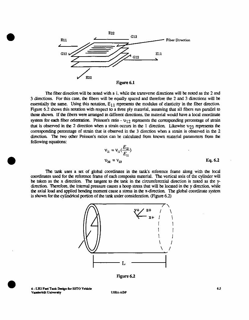
The most notable difference between composite materials and isotropic materials is the presence of fibers intimately bonded to the matrix material. An initial examination leads to the correct assumption that the composite material will have very different properties in the fiber direction than it will in the transverse (across fiber) direction. Whereas an isotropic material has a single value of modulus of elasticity, a composite material has a modulus of elasticity in the fiber direction and a modulus of elasticity in the transverse dimtion. Likewise, composites have different strength values in the two directions. An isotropic material has a single value of Poisson's ratio, unlike a composite material that has four Poisson's ratios, two of which are independent values. The notation that will be used with respect to composite materials is shown in Figure 6.1.
6 - LH2 Fuel Tank Design for m0 Vehicle vanderbat uaivcrdty USRA- ADP
6.4
E22 , G12 J E l l
' E l l '/r G12 \
Fiber Direction
Figure 6.1
The fiber direction will be noted with a 1, while the transverse directions will be noted as the 2 and 3 directions. For this case, the fibers will be equally spaced and therefore the 2 and 3 directions will be essentially the same. Using this notation, E11 represents the modulus of elasticity in the fiber direction. Figure 6.2 shows this notation with respect to a three ply material, assuming that all fibers run parallel to those shown. If the fibers were arranged in different directions, the material would have a local coordinate system for each fiber orientation. Poisson's ratio - u 12 represents the corresponding percentage of strain that is observed in the 2 direction when a strain occurs in the 1 direction. Likewise 1123 represents the corresponding percentage of strain that is observed in the 3 direction when a strain is observed in the 2 direction. The two other Poisson's ratios can be calculated from known material parameters from the following equations:
'32 = '23 Eq. 6.2
The tank uses a set of global coordinates in the tank's reference frame along with the local coordinates used for the reference frame of each composite material. The vertical axis of the cylinder wiU be taken as the x direction. The tangent to the tank in the circumferential direction is noted as the y- direction. Therefore, the internal pressure causes a hoop stress that will be located in the y direction, while the axial load and applied bending moment cause a stress in the x-direction. The global coordinate system is shown for the cylindrical portion of the tank under consideration. (Figure 6.2)
[ \
\ I I
I I I - I \ I \ /
K+,/ '
Y
6 - LH2 Fuel Tank Dcsipn for !M'O Vehide 6.3 - Vandcrbnt Univedg USRA-ADP

I
"he goal associated with this study of lamination theory is to accurately approximate the laminate properties in the x-y coordinate system knowing the number of layers in the tank wall, the orientation of the fibers in each layer, and the material properties of each layer. This involves approximating the behavior of the individual layers of fibers and matrix as a single material with isotropic properties. The first assumption that is made to accomplish this is that the plane sections of material remain plane. This assumes that the layers of the material have an infinitely strong bond that will not separate or yield during the loading of the material. W e bond failure in composite materials is not impossible, it will not be considered in this preliminary design effort.
Hooke's law for composite materials is given as:
0 1 v21
El 1 - E, - - E l 1 0 1 1
0 2 2 Eq. 6.3
where i=l,2,3, .... ,nmat and nmat = # of materials present in the laminate. (The material properties in the matrix are inputs to the buckling program.) 'Ihe three by three matrix above is denoted as the S-matrix for layer i and its inverse is the stiffness matrix known as the Qi-matrix. Using the assumption above that plane sections remain plane, it is obsewed that the strains in each layer must be equal for a given global direction:
a (&,)I= (E,)? =*****= (E,),,,,
(yxy ( ~ y ) 1 = ( ~ y ) 2 =*****= (Ey), .yL. Eq. 6.4
(Y xy )2 =.*.**= (yxy ),lycr
Therefore, the strains in each layer in equation 6.3 can be converted into strains in the global directions and must be equal for all layers. Using this transformation, the stiffness matrix (Q) of each material is transferred into the stiffness matrix in the global coordinates (Q)i for each layer, i=1,2,3, ... slayer. The force per unit width is calculated for each global coordinate direction knowing the stress in each direction and the thickness of each layer ( both are inputs to program).
2 Fk = O,tj = N, (N, is the force per unit width)
qi = cTYiti = N, (4 is the force per unit width)
nl er
h e r
Eq. 6.5 i= 1
YF' = z V ' t. = N, (NV is the shear force per unit width) i=l
6 - LH2 Fuel Tank Design for SSTO VeWe VanderbPt UdversiQ USRA-ADP
6.6

Having the Q matrix for each layer of the laminate, the calculation of the total laminate matrices can be made: A, B, and D. The laminate matrices are computed by summing the effect that each layer has on the overall properties of the laminate, assuming that the amount of effect that a particular layer has is proportional to the thickness of that layer. The matrices are calculated from the following equations:
a
h = l 1 nlayer
h = l B , = - C 'QJh; - h t - , ]
- -
[ i j = 1, 2 ,6]
[i,j = 1, 2, 61 Eq. 6.6
[ i j = 1, 2, 61
The A matrix represents the extensional stiffness matrix relating the in-plane stress resultants ("s) to the mid-surface strains (EO'S) (Vinson and Sierakowski'o ,1987) as:
Eq. 6.7
Similarly, the D matrix is the flexural stiffness matrix relating the stress couples (M's) to the curvatures (IC's). The B matrix relates Ms to EO'S and Ns to IC's and is called the bending-stretching coupling matrix. It should be noted that a laminated structure can have bending-stretching coupling even if all lamina are isotropic, for example in our case, a laminate composed of one lamina of graphite epoxy and another of Boron Aluminum separated by a honeycomb interior. In fact, only when the structure is exactly symmetric about its middle surface are all of the Bij components equal to zero, and this requires symmetry in laminae properties, orientation, and location from the middle surface. Stretching shearing coupling occurs when A16 A26 are non zero. Twisting stretching coupling occurs when the B16 B26 terms are non-zero. usually, the 16 and 26 terms are avoided by proper stacking sequences. For the present design, the tank lamina are carefully chosen to insure that the B-matrix, A16, and A26, are equal to zero.
V i n and Sierakowski'o (1987). gives the buckling equations for a circular cylindrical shell shown in Figure 6.3 with a mean radius R, wall thickness h, and length L, subjected to a compressive load P, and a beam-type bending moment M.
6 - LH2 Fuel Tank Design for SSTO VehMc Vanderbilt University USRA-ADP
6.7
c-J- -

P
T
T
P
M
Figure 6.3
Making the assumptions that special anisotropy exists, that is ( )I6 = ( )26 = 0 for the A, B, and D matrices, that prebuckled deformations are not taken into account, and that the ends of the cylindrical shell are supported by rings rigid in their plane, but have no resistance to rotation or bending out of their plane, the buckling load for the case that assumes mid-plane symmetry (that is B i j 4 ) and n > 4 is given as:
e All A, - A; D D , y2L4 = m 2 ( l + 2 J q 3 2 + - p 4 ) + N x,
A,, + ( - - 2 A 1 2 ) p 2 + A D P 4 X D l l Dl1 Dll x ~ ~ ’ D , , R *
A,
Eq. 6.8
where: m = # of buckle half waves in the axial direction n = # of buckle waves in the circumferential direction
nL x Rm
p = - y = 1.0-.901(1- e*) y = 1.0-.73l(l-e*)
for axial loads for bending moments
1 R + = 29.8(14,0,)J
Eq. 6.9
Eq. 6.10 Eq. 6.11
Eq. 6.12
Here, gamma is an empirical (knock down) factor that insures that the calculated buckling load will be conservative wjth respect to all experimental data that are available. The critical buckling load is found by varying the integers m and n to determine the minimum value of N I~ which will be the predicted buckling load. The number of buckle waves in the circumferential direction must be greater than 4, in order to agree with experimental evidence that a structure that buckles due to circumferential waves will form a four comer, saw-toothed shape that corresponds to n>4.
6 - LH2 Fuel Tank Design for SsrO VehMe VnnderbDt University
6.8 USRA-ADP
'The tank undergoes simultaneously loading in that the tank experiences axial load, bending moment and internal pressure at the same time. Therefore, the Miner's Rule (Law of Cumulative Damage) will be used to determine the critical axial load - bending moment couple for the tank. To do this, we take the applied axial load per unit circumference divided by the critical axial load per unit circumference and add it to the applied bending moment per unit circumference divided by the critical value of this:
Eq. 6.13 xbdw < 1 N + = O D l y r r r O n
r e -
N f c r m d ,bmd
N
If this summation is less than 1, the design is predicted to be stable The internal pressure will act to stabilize the tank, but will not be accounted for in this study. It is expected that the stability gained from the internal pressure will make up for imperfections that will lead to instability in the tank that are also unaccounted for in this preliminary effort,
To further insure against tank failure, the internal stresses that the applied loads cause must not exceed the allowable material stresses. This design uses a FORTRAN program which calculates the stresses in each layer of the material in the fiber direction and the transverse direction and divides these values by the allowable stresses. When these values are all less than 1, the tank is predicted to have sufficient strength to undergo both the x-direction stresses caused by the applied loading and the y-direction stresses, a hoop stress caused by the internal pressure of the vessel.
The final computation that the FORTRAN program makes is to determine the total mass of the tank. Knowing the outer radius of the vessel and the thickness of each layer, the total volume of each material in the structure can be calculated. 'The volume of each layer is multiplied by the density of that layer to give the mass of each layer, which are then added to result in the total tank mass.
The resulting tank configurations are calculated using a FORTRAN program of the above theory. The results can be found in section 6.12 0 6.6 Heat Transfer
6.6.1 Overview
The TR model examines the heat transfer through the wall of the fuel tank. Based upon the assumption that the fluid contained within the tank is static, the heat transfer is considered to be largely conductive. The model described in this analysis assumes that convective and radiative heat transfer are negligible. Calculations were made only with respect to conductive heat transfer.
The control of heat transfer through the tank wall is important for at least two reasons. Excessive pressures within the tank due to thermal expansion may cause gas leakage or catastrophic failure. Frost collecting on the outside surface of the tank will increase the mass of the aircraft and may cause additional complications during flight This design compares the total TR of NASA's current project to the total TR of the selected composite materials of this design. If the TR of this design is greater than the TR of NASA's current project, then an additional TR is not required. On the other hand, if the TR of this design is less than that of NASA's current project, additional TR is required.
Additional TR can be achieved by adding one last layer of material to the outside of the tank. The material used to make up the deficit of TR will be insulation. This portion of the design evaluates the properties of TR and mass of different insulation materials. Insulation will be selected based upon the superior characteristics of its TR at cryogenic temperatures and material density.
6 - LH2 Fuel Tank Dosbrn for SSTO Vehkle 6.9 - Vmderbilt Ualversity USRAADP
a 6.63 Thermal Resistance Model
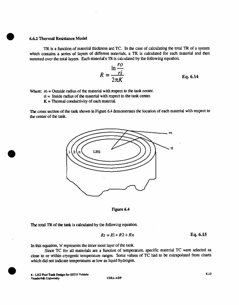
TR is a function of material thickness and TC. In the case of calculating the total TR of a system which contains a series of layers of different materials, a TR is calculated for each material and then summed over the total layers. Each material's TR is calculated by the following equation.
ro In - Eq. 6.14
Where: ID = Outside radius of the material with respect to the tank center. ri = Inside radius of the material with respect to the tank center. K = 'Ihermal conductivity of each material.
The cross section of the tank shown in Figure 6.4 demonstrates the location of each material with respect to the center of the tank.
Figure 6.4
The total TR of the tank is calculated by the following equation.
Rt = R1+ R2+ Rn
In this equation, 'n' represents the inner most layer of the tank.
ro
\ r i -
Eq. 6.15
Since TC for all materials are a function of temperature, specific material TC were selected as close to or within cryogenic temperature ranges. Some values of TC had to be extrapolated from charts which did not indicate temperatures as low as liquid hydrogen.
6 - LH2 Fuel Tank Design for ST0 Vehicle Vaaderbilt Ualverslty USRA- ADP
6.10
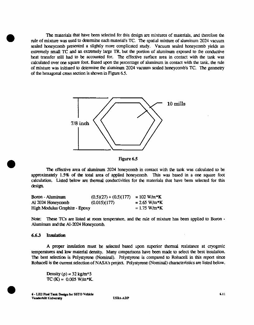
The materials that have been selected for this design are mixtures of materials, and therefore the rule of mixture was used to determine each material's TC. The spatial mixture of aluminum 2024 vacuum sealed honeycomb presented a slightly more complicated study. Vacuum sealed honeycomb yields an extremely small TC and an extremely large TR, but the portion of aluminum exposed to the conductive heat transfer still had to be accounted for. The effective surface area in contact with the tank was calculated over one square foot. Based upon the percentage of aluminum in contact with the tank, the rule of mixture was initiated to determine the aluminum 2024 vacuum sealed honeycombs TC. The geometry of the hexagonal cross section is shown in Figure 6.5.
a
Figure 6.5
The effective area of aluminum 2024 honeycomb in contact with the tank was calculated to be approximately 1.5% of the total area of applied honeycomb. This was based in a one square foot calculation. Listed below are thermal conductivities for the materials that have been selected for this design
Boron - Aluminum (0.5)(27) + (0.5)(177) = 102 W h * K Al2024 Honeycomb (0.015)( 177) = 2.65 W h * K High Modulus Graphite - Epoxy = 1.75 W h * K
Note: Aluminum and the Al-2024 Honeycomb.
These TCs are listed at room temperature, and the rule of mixture has been applied to Boron -
6.63 Insulation
A proper insulation must be selected based upon superior thermal resistance at cryogenic temperatures and low material density. Many comparisons have been made to select the best insulation The best selection is Polystyrene (Nominal). Polystyrene is compared to Rohacell in this report since Rohacell is the current selection of NASA's project. Polystyrene (Nominal) characteristics are listed below.
Density (p) = 32 kg/mA3 TC (K) = 0.005 W h * K .
6 - LH2 Fucl Tank D e s h for SSTO Vehlclc 6.1 1 s
Vanderbilt University USRA-ADP
Note: 'Ihese data were found without extrapolation. (Nonmetallic Materials and Composites at Low Temperatures, 195)
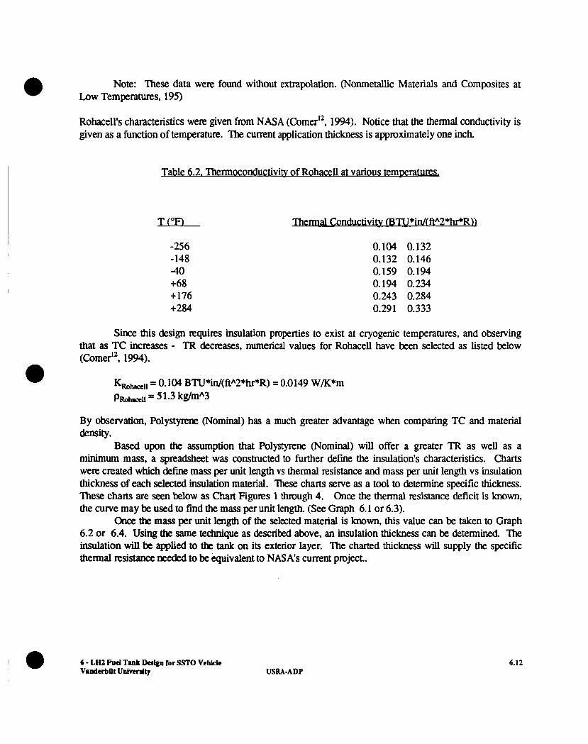
Rohacell's characteristics were given from NASA (Comer'*, 1994). Notice that the thermal conductivity is given as a function of temperature. The current application thickness is approximately one inch.
Table 6.2. Thermoconductivity of Rohacell at vanous te mxraturesA
-256 -148 40 +68 +176 +284
Thermal Conductivitv (BTU *in/(ftA2*WRU
0.104 0.132 0.132 0.146 0.159 0.194 0.194 0.234 0.243 0.284 0.291 0.333
Since this design requires insulation properties to exist at cryogenic temperatures, and observing that as TC increases - TR decreases, numerical values for Rohacell have been selected as listed below (Comer'*. 1994).
e K,,-,, = 0.104 BTU*in/(ftA2*hPR) = 0.0149 W/K*m p,,-,, = 5 1.3 kg/mA3
By observation, Polystyrene (Nominal) has a much greater advantage when comparing TC and material density.
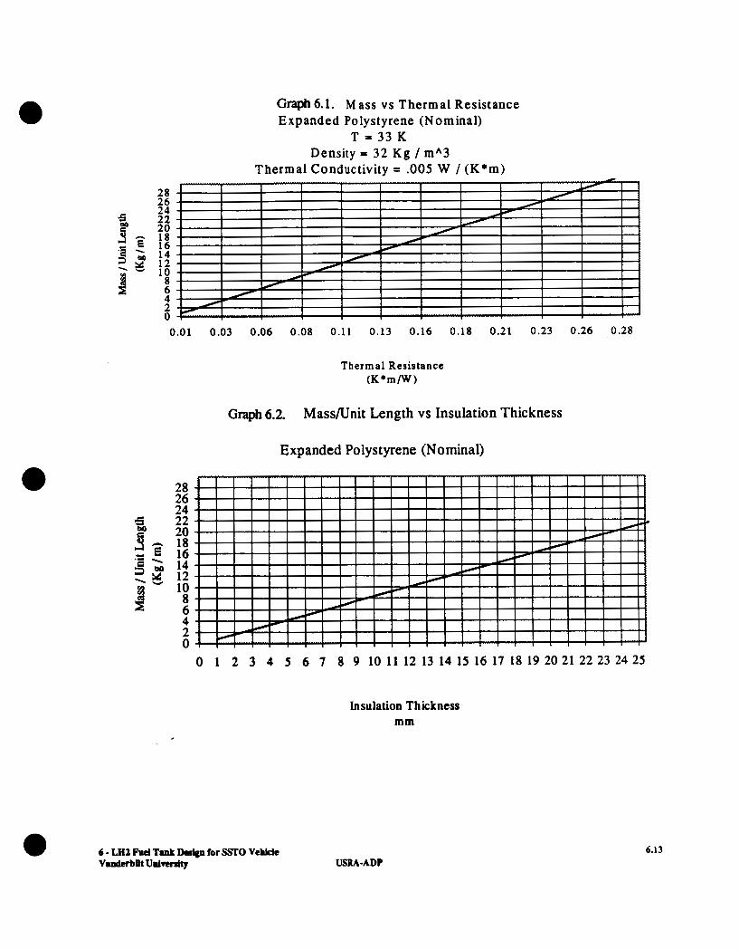
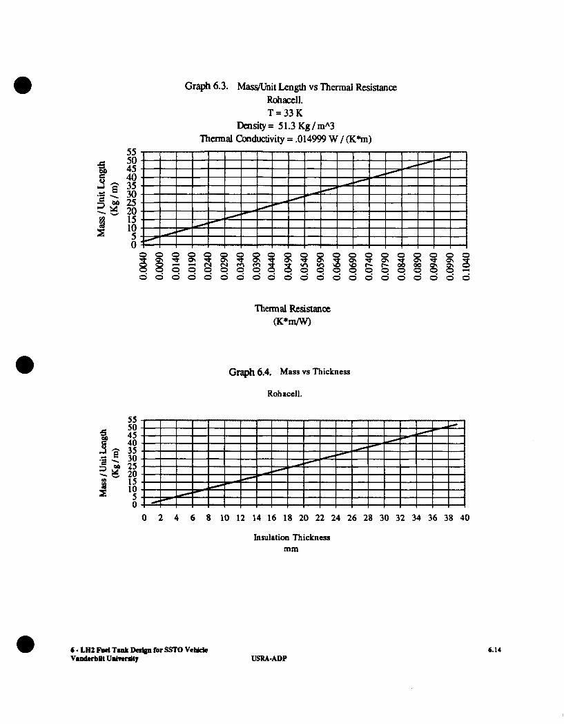
Based upon the assumption that Polystyrene (Nominal) wil l offer a greater TR as well as a minimum mass, a spreadsheet was constructed to further defme the insulation's characteristics. Charts were created which define mass per unit length vs thermal resistance and mass per unit length vs insulation thickness of each selected insulation material. 'Ihese cham serve as a tool to determine specific thickness. 'Ihese cham are seen below as Chart Figures 1 through 4. Once the thermal resistance deficit is known, the curve may be used to find the mass per unit length. (See Graph 6.1 or 6.3).
Chce the mas per unit length of the selected material is known, this value can be taken to Graph 6.2 or 6.4. Using the same technique as described above, an insulation thickness can be determined. The insulation will be applied to the tank on its exterior layer. The charted thickness will supply the specific thermal resistance needed to be equivalent to NASA's current project..
USRA-ADP 6.12
28 26 24 22 20 18 16 14 12 10 8 6 4 2 0
Graph 6.1. Mass vs Thermal Resistance Expanded Polystyrene (Nominal)
T = 3 3 K Density = 32 Kg / mA3
Thermal Conductivity = .OOS W / ( K * m )
0.01 0.03 0.06 0.08 0.11 0.13 0.16 0.18 0.21 0.23 0.26 0.28
Thermal Resistance ( K * m / W )
Graph 6.2. Mass/Unit Length vs Insulation Thickness
Expanded Polystyrene (Nominal)
28 26 24 22 20 18 16 14 12 10 8 6 4 2 0
Insulation Thickness mm
6 - LH2 Fud Tank Design for SSI'O Vehlde v.ndcrbilt Unlwrdty USRA-ADP
6.13
Graph 6.3. M W n i t Length vs Thermal Resistance Rohacell. T = 3 3 K
Density= 51.3 Kg/m*3 Thennal conductivity = .014999 W / 6%)
55 50 45 40 35 30 25 20 15 10 5 0
3 8 CI
a 4
8 a o a z z o , o , 8 3 z 5 0 0 0 8 0 0 0 0 0 0 0
Thermal Resistance (K*m/w)
Graph 6.4. Mass vs Thickness
0 3 8
0
?i 0
3 CI
0
Rohacell.
55 50
40
3 OD 25 3 15
0
* 45
9 , 35 .s . 30 Zr g 20
E 's 0 2 4 6 8 10 12 14 16 18 20 22 24 26 28 30 32 34 36 38 40
Insulation Thickness mm
6 - LA2 Fuel Tank Dafoa for SSFO Vebkk V.ndCrbPt UnlTemity
6.14 USRAADP

Note that the equation used to plot all graphs were created from the following equation ro In - 0
- ri R-- 27cK Eq. 6.16
Where a unit length of the cylindrical section was used. Only dimensions of insulation thickness were varied to redefine thermal resistance as a function of thickness.
6.6.4 Defining the Total Insulation Mass
Once the total insulation thickness is known, the volume of the insulation can be determined. Recall that the insulation will be applied to the exterior section of the tank, thus reducing the inside diameter. Since the outer diameter of the tank is fixed at 33 1 inches, and the volume of the tank is fixed at 46241.7 ft3, the design required a new length to be established. Also recall that this design only relates to the cylindrical section of the tank ( i.e. the end caps excluded in this analysis ). This new length can be calculated as shown.
* Volume L =
nr2 Eq. 6.17
Since a new value of length Q has been established, the volume of insulation can be calculated by the following equation.
v (insulation) = nL(ro2 - ri2 ) Eq. 6.18
Figure 6.6
6 - LH2 Fuel Tank Design for SSTO Vehkle VanderbUt University USRA-ADP
6.15
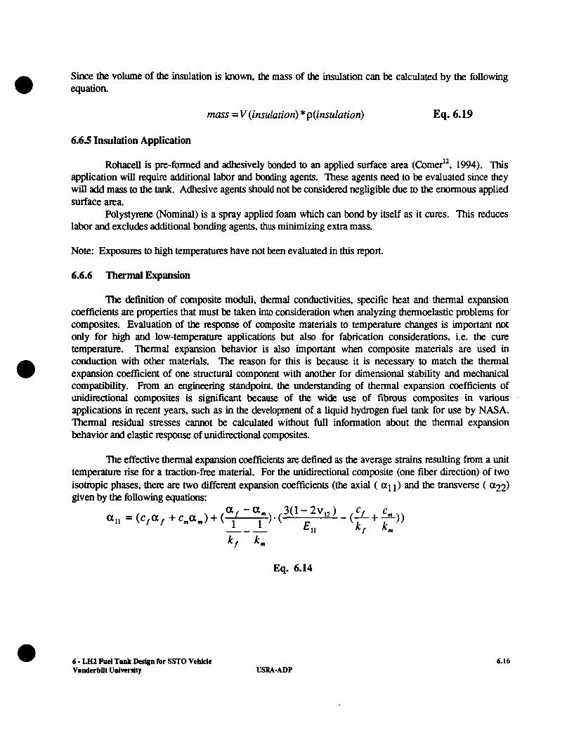
Since the volume of the insulation is known, the mass of the insulation can be calculated by the following 0 equation.
mass = V (insulation) * p(insu1ation) Eq. 6.19
6.65 Insulation Application
Rohacell is pre-formed and adhesively bonded to an applied surface area (Comer", 1994). This application will require additional labor and bonding agents. These agents need to be evaluated since they will add mass to the tank. Adhesive agents should not be considered negligible due to the enormous applied surface area.
Polystyrene (Nominal) is a spray applied foam which can bond by itself as it cures. This reduces labor and excludes additional bonding agents, thus minimizing extra mass.
Note: Exposures to high temperatures have not been evaluated in this report.
6.6.6 Thermal Expansion
'Ihe definition of composite moduli, thermal conductivities, specific heat and thermal expansion coefficients are properties that must be taken into consideration when analyzing thermoelastic problems for composites. Evaluation of the response of composite materials to temperature changes is important not only for high and low-tempemure applications but also for fabrication considerations, Le. the cure temperature. Thermal expansion behavior is also important when composite materials are used in conduction with other materials. The reason for this is because it is necessary to match the thermal expansion coefficient of one structural component with another for dimensional stability and mechanical compatibility. From an engineering standpoint, the understanding of thermal expansion coefficients of unidirectional composites is significant because of the wide use of fibrous composites in various applications in recent years, such as in the development of a liquid hydrogen fuel tank for use by NASA. Thermal residual stresses cannot be calculated without full information about the thermal expansion behavior and elastic response of unidirectional composites.
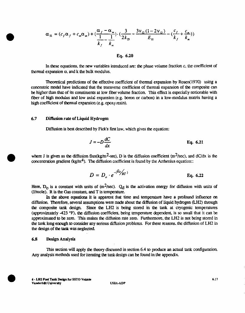
The effective thermal expansion coefficients are defined as the average strains resulting from a unit temperature rise for a traction-free material. For the unidirectional composite (one fiber direction) of two isotropic phases, there are two different expansion coefficients (the axial ( a1 1 ) and the transverse ( "22) given by the following equations:
k f k m
Eq. 6.14
6 - LH2 Fuel Tank Design for SSTO Vehicle 6.16 Vanderbilt University USRA-ADP
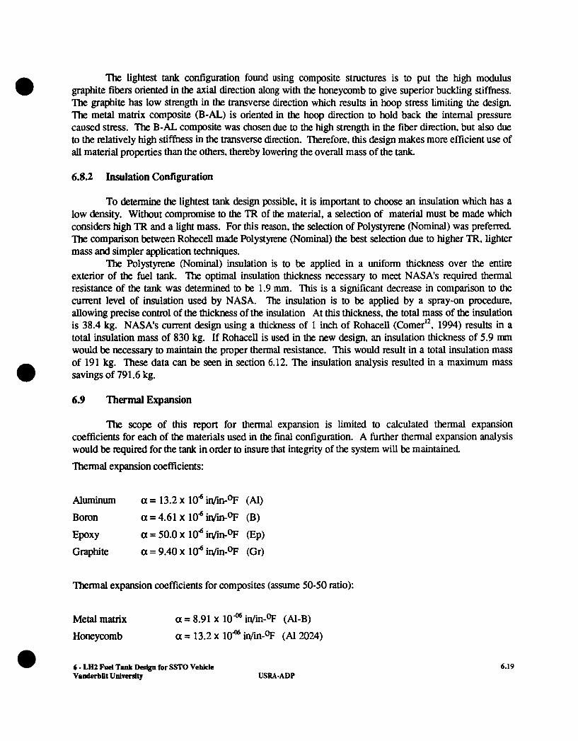
Eq. 6.20
In these equations, the new variables introduced are: the phase volume fraction c, the coefficient of thermal expansion a, and k the bulk modulus.
Theoretical predictions of the effective coefficient of thermal expansion by Rosen( 1970) using a concentric model have indicated that the transverse coefficient of thermal expansion of the composite can be higher than that of its constituents at low fiber volume fraction. This effect is especially noticeable with fiber of high modulus and low axial expansion (e.g. boron or carbon) in a low-modulus matrix having a high coefficient of thermal expansion (e.g. epoxy resin).
6.7 Diffusion rate of Liquid Hydrogen
Diffusion is best described by Fick's first law, which gives the equation:
dC dr
J = - D - Eq. 6.21
where J is given as the diffusion flux(lcg/m2-sec), D is the diffusion coefficient (m2/sec), and dUdx is the concentration gradient (kg/m4). The diffusion coefficient is found by the Anhenius equation::
Eq. 6.22
Here, Do is a constant with units of (m2/sec). Qd is the activation energy for diffusion with units of (Jhole). R is the Gas constant, and T is temperature.
In the above equations it is apparent that time and temperature have a profound influence on diffusion. Therefore, several assumptions were made about the diffusion of liquid hydrogen (LH2) through the composite tank design Since the LH2 is being stored in the tank at clyogenic temperatures (approximately 423 OF), the diffusion coefficient, being temperature dependent, is so small that it can be approximated to be zero. This makes the diffusion rate zero. Furthermore, the LH2 is not being stored in the tank long enough to consider any serious diffusion problems. For these reasons, the diffusion of LH2 in the design of the tanit was neglected,
6.8 Design Analysis
This section wil l apply the theory discussed in section 6.4 to produce an actual tank configuration Any analysis methods used for iterating the tank design can be found in the appendix.
6 - LH2 Fuel Tank Des&n for SSTO Vehicle VamJerbDt University
a 6.17 USRAADP

a 6.8.1 Structural Configuration
To determine the lightest tank possible, each configuration discussed earlier was tested to determine the lightest tank possible. For a given configuration, the total wall thickness, each layer thickness, orientation of the fibers in a layer, and the honeycomb thickness were chosen randomly. The weight of the tank was then calculated by the method discussed previously. The tank parameters were varied to ensure buckling stability, strength limitations, and the lightest weight. The optimum designs for each configuration are shown below:
Boron - Aluminum (solid wall) wall thickness = .78 in. tank length = 580.8 in. tank mass = 47,440 lbm. all fibers in axial direction
Boron Aluminum (honeycomb middle) wall thickness = .78 in. thickness of B-AL, outside = .14 in. thickness of honeycomb = .5 thickness of B-AL,, inside = 0.14 in tank length = 580.8 in. tank mass = 22,415 lbm. all fibers in the axial direction
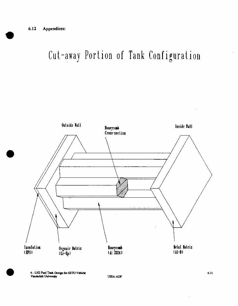
Boron Aluminum, Graphite, Honeycomb 0 wall thickness= 1.25 in. thickness of B-AL, outside = 0.0375 in. thickness of graphite, outside = 0.1145 in thickness of honeycomb = .946 in. thickness of graphite, inside = 0.1 145 in thickness of B-AL, inside = 0.0375 in. tank length = 584 in. tank mass = 14,845 lbm. all graphite fibers in the axial direction all AL-B fibers in the hoop direction
The initial assumption made that the tank would be stiffness limited is accurate only to a degree. A single material tank is strongly stiffness limited, but the addition of the honeycomb allows the thickness of the composite.material to decrease as the thickness of the honeycomb increases. Therefore, the actual limitation on our design is a combination of buckiling and strength. The thickness of the honeycomb increases to provide a higher buckling resistance, but as this happens, the actual load bearing sections decrease in thickness. Therefore, optimum design occurs when the honeycomb thickness increases and leaves the critical amount of wall thickness to withhold the internal pressure. The circumferential strength can be increased by orientating fibers in this direction along with the axial fibers used to provide stiffness.
6 - LH2 Fuel Tank Deslgn for SSTO Vehicle Vauderbilt University USRA-ADP
6.18
The lightest tank configuration found using composite structures is to put the high modulus graplute fibers oriented in the axial direction along with the honeycomb to give superior buckling stiffness. The graplute has low strength in the transverse direction which results in hoop stress limiting the design. The metal matrix composite (B-AL) is oriented in the hoop direction to hold back the internal pressure caused stress. The B-AL composite was chosen due to the high strength in the fiber direction, but also due to the relatively high stiffness in the transverse direction. Therefore, this design makes more efficient use of all material properties than the others, thereby lowering the overall mass of the tank.
a
6.8.2 Insulation Configuration
To determine the lightest tank design possible, it is important to choose an insulation which has a low density. Without compromise to the TR of the material, a selection of material must be made which considers high TR and a light mass. For this reason, the selection of Polystyrene (Nominal) was preferred. The comparison between Rohecell made Polystyrene (Nominal) the best selection due to higher TR, lighter mass and simpler application techniques.
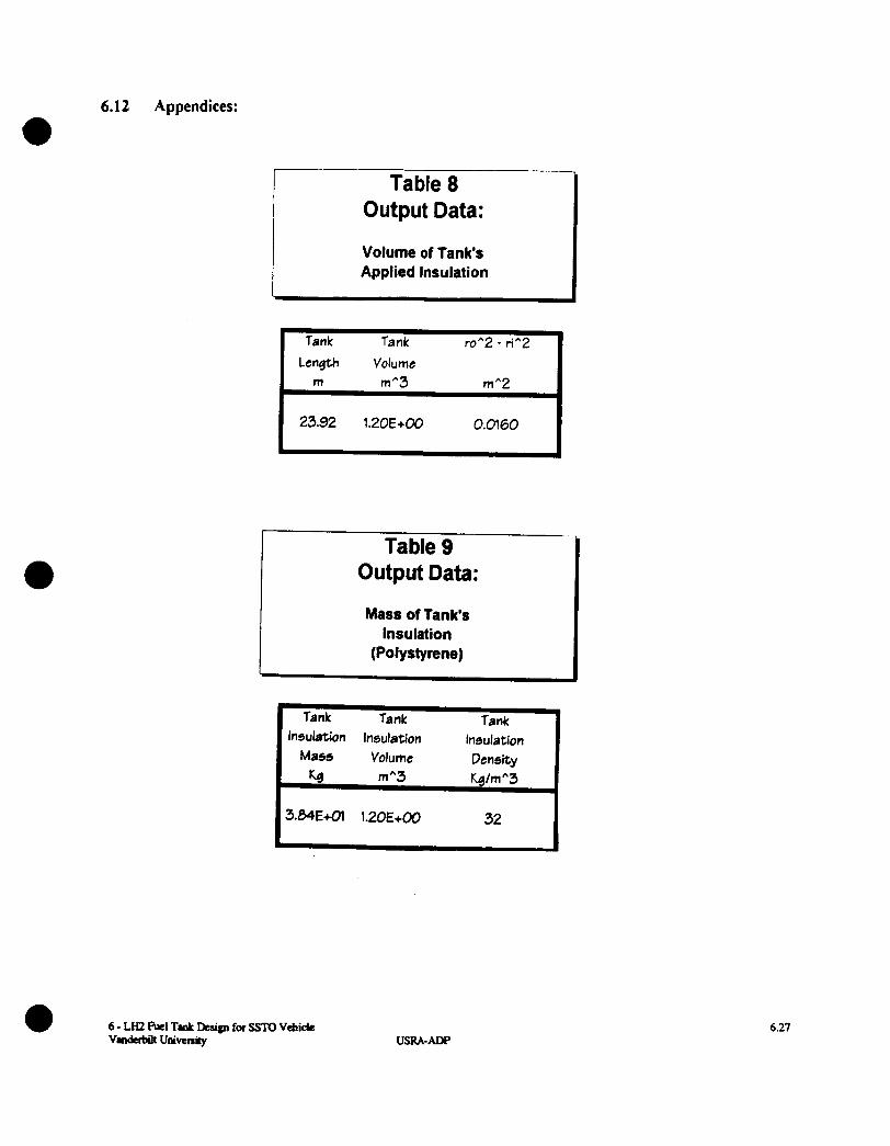
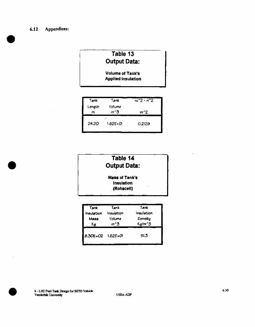
The Polystyrene (Nominal) insulation is to be applied in a uniform thickness over the entire exterior of the fuel tank. The optimal insulation thickness necessary to meet NASA's required thermal resistance of the tank was determined to be 1.9 mm. This is a significant decrease in comparison to the current level of insulation used by NASA. The insulation is to be applied by a spray-on procedure, allowing precise control of the thickness of the insulation At this thickness, the total mass of the insulation is 38.4 kg. NASA's current design using a thickness of 1 inch of Rohacell (Comeri2, 1994) results in a total insulation mass of 830 kg. If Rohacell is used in the new design, an insulation thickness of 5.9 mm would be necessary to maintain the proper thermal resistance. This would result in a total insulation mass of 191 kg. These data can be seen in section 6.12. The insulation analysis resulted in a maximum mass savings of 791.6 kg.
6.9 ThermalExpansion
The scope of this report for thermal expansion is limited to calculated thermal expansion coefficients for each of the materials used in the final configuration. A further thermal expansion analysis would be required for the tank in order to insure that integrity of the system will be maintained Thermal expansion coefficients:
Aluminum Boron
EPXY Graphite
a = 13.2 x 10' Win-% (Al) a = 4.61 x 10' Win-% (B) a = 50.0 x 10' Wl-% (Ep) a = 9.40 x 10' Win-% (Gr)
Thermal expansion coefficients for composites (assume 50-50 ratio):
Metal matrix Honeycomb
a = 8.91 x 10" in/in-% (AI-B) a = 13.2 x 10" Win-% (Al2024)
6 - LH2 Fuel Tank Design for SSTO Vehlde 6.19 Vanderbilt University USRA-ADP

Organic matrix
6.10 Recommendations
a = 29.7 X loa Wm-9 (Gr-Ep) a It must be noted that this is a preliminary study. Topics for further research must include fracture,
stresses due to thermal expansion, interface with vehicle and the addition of the hemispherical ends of the tank.
6 - LH2 Fud Tank Design for SSTO Vehlde Vamiefint university USRA-ADP
6.20
6.11
(1)
References (in order of use)
"Comparison of Materials." Materials Engineering, December 1989: 79 - 241.
(2) ComDosites: Engineered Materials Handboo k. Volume 1, New York: ASM International, 1987: 27, 167.
(3) Hackman, Lloyd, "Sandwich Construction and Design," Analvsis and Desim of Flight Vehicle Struct ures, C12.1 - C12.8. Edited by Elmer F. Bruhn, Indianapolis: S.R. Jacobs & Associates, 1973.
(4) Kasen, M.B., "Mechanical Performance of Graphite and Aramid Reinforced Composites at Cryogenic Temperatures," Advances in Cryog -enic Engineering. Volume 28, 165 - 177. Edited by R.P. Reed and A.F. Clark, New York: Plenum Press, 1982.
(5 ) Rosen, B.W. Proc. Roy. SOC. Lond. Ser. A 319 (1970) 70.
(6) Graham, Bart. Reference 1, Meeting at MSFC. January, 1994.
(7) Graham, Bart. Reference 2, Telephone conversation, February, 1994.
(8)
(9)
Graham, Bart. Reference 3, Telephone conversation, March, 1994.
Graham, Bart and Paul Luz. LaRC 001 SSV Configuration, December 10,1993.
(10) Vinson, J. R. and Sierakowski, R. L. The Behavior of Structures Co mmsed - o f Composite Materials. Dordrecht: Martinus Nijhoff Publishers, 1987.
(1 1) Mark's Standard Handboo k for Mechanical Engineers, Ninth Edition, New York: McGraw - Hill, 1987: Sections 19-36
(12) Comer, Gene. Telephone conversation, March, 1994
(13) Clark, A.F., Reed, R.P. and Hartwig, G. Nonmetallic Materials and Co m-Dosites at Low Ternperaturn , New York: Plenum Press, 1979.
6 - LH2 Fuel Tank Deslgn for SSTO Vehide 6.21 Vsnderbnt University USRAADP
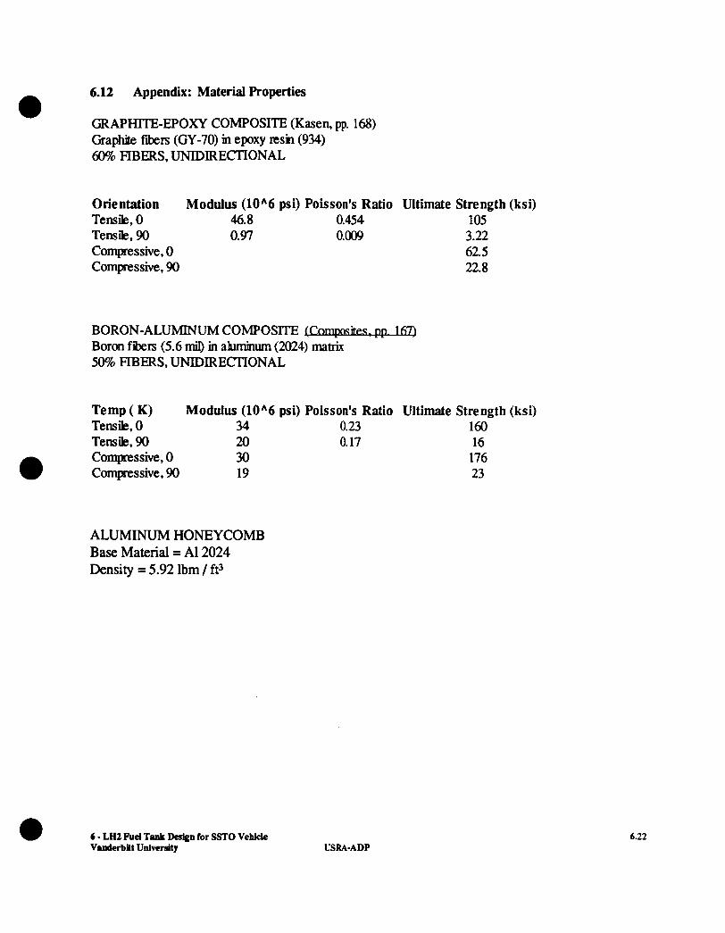
6.12 Appendix: Material Properties
GRAPHITE-EPOXY COMPOSITE (Kasen, pp. 168) e
Gra- fibers (GY-70) m epoxy m n (934) 60% FIBERS, UNIDIRECTIONAL
Orientation Modulus (10A6 psi) Poisson's Ratio Ultimate Strength (ksi) Tensile, 0 46.8 0.454 105 Tensile, 90 0.97 0.009 3.22 Compressive, 0 62.5 Compressive, 90 22.8
BORON-ALUMINUM COMPOSITE Boron fibers (5.6 mii) in aluminum (2024) matrix 50% FIBERS, UNIDIRECTIONAL
Temp ( K) Modulus (10A6 psi) Poisson's Ratio Ultimate Strength (ksi) Tensile, 0 34 0.23 160 Tensile, 90 20 0.17 16 Compressive, 0 30 176 Compressive, 90 19 23
ALUMINUM HONEYCOMB Base Material = A1 2024 Density = 5.92 lbm / ft3
6 - LH2 Fuel Tank Dedgn for SSTO Vehlcle Vanderbllt UniwrsJty USRA-ADP
6.22
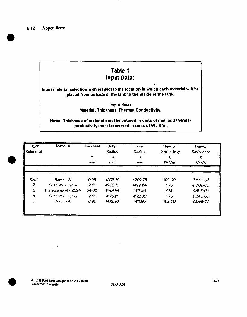
6.12 Appendices:
Table 1 I Input Data:
Input material selection with respect to the location in which each material will be placed from outside of the tank to the inside of the tank.
Input data: Material, Thickness, Thermal Conductivity.
I Note: Thickness of material must be entered in units of mm, and thermal conductivity must be entered in units of W I K'm.
Layer Material Thickness Outer inner Thermal Thermal Reference Radius Radius Conductivity Resi5tance
t ro ri K R mm mm mm WK'm K'mMI
Ext. 1 Boron - AI 0.95 4203.70 4202.75 102.00 3.54E-07 2 Graphite - Epoxy 2.91 4202.75 41 99.84 1.75 6.30E-05 3 Honeycomb AI - 2024 24.03 4199.04 4175.01 2.65 3.45E-04 4 Graphite - Epoxy 2.91 4175.01 4172.90 1.75 6.34E-05 5 Boron - Ai 0.95 4172.90 4171.95 102.00 3.56E-07
6 - LH2 Fuel Tmk Design for SSTO Vehicle vradcrbilt Uaivcnily USRA-ADP
6.23
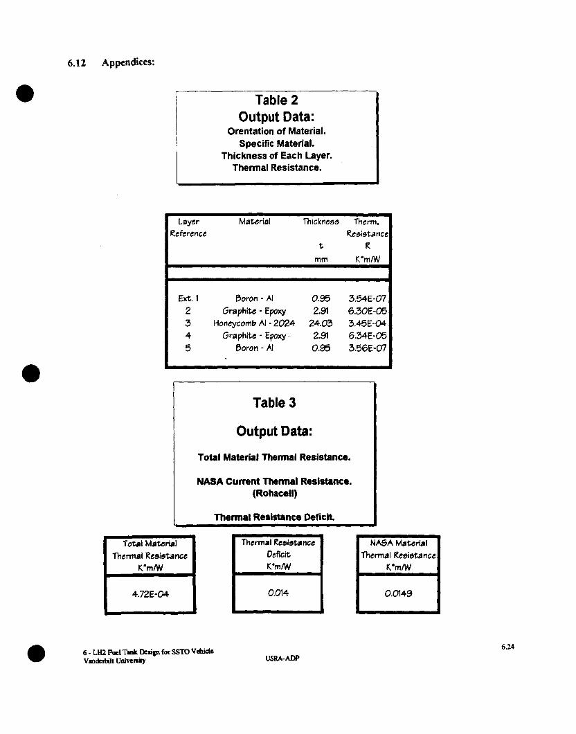
6.12 Appendices:
I
I Table 2 I Output Data:
Orentation of Material. Specific Material.
Thickness of Each Layer. Thermal Resistance.
Layer Material Thickness Therm. Reference Resistance
Ext. 1 Boron - AI 0.95 3.54E-07 2 Graphite - Epoxy 2.91 6.30E-05
4 Graphite - Epoxy. 2.91 6.34E-05 5 Boron - AI 0.95 3.56E-07
3 Honeycomb AI - 2024 24.03 3.45E-04
Table 3
Output Data:
Total Material Thermal Resistance.
NASA Current Thermal Resistance. (Ro hacell)
I Thermal Resistance Deficit.
Total Matcrial Thermal Resistance H 4.72E-04
Thermal Resistance Deficit
I
Thermal Resistance
0.049 I 6 - LH2 Rrl TrJr Dcign for SSTO Vehick VIlrderbilt Univenity USRA-ADP
6.24

6.1 2 Appendices:
*
Table 5 Input Data:
Insulation and material selection with respect to the location it will be.placed from outside of the tank to the inside of the tank.
Input data: Material, Thickness, Thermal Conductivity.
Note: Thickness of material must be entered in units of mm, and thermal conductivity must be entered in units of W I K*m.
- i Table 4 I
Output Data:
I Length of lank's Cylindrical Section.
Tank Fluid ri (Liner) Length Volume
m m *3 rn
23.92 1309.42 4.17
Layer Material Thicknees Outer inner Thermal Thermal Reference Radius Radius Conductivity Resistance
t m r i K R rnm mm mm W/K'm K'mlW
Insula tion Polystyrene 1.90 4203.70 4201.80 0.01 1.44E-02 Ext. 1 Boron - AI 0.95 4201.00 4200.85 102.00 3.9E-07 2 Graphite - Epoxy 2.91 4200.05 4197.94 1.75 6.30E-05 3 Honeicornb AI - 2024 24.03 4197.94 4173.91 2.65 3.45E-04 4 Graphite - Epoxy 2.91 4173.91 4171.00 1 .E 6.34E-05 5 Boron - AI 0.95 4171.00 4170.05 102.00 3.56E-07
6 - LH2 Fucl T d for SSTO VehiClC Vmderbilt Univenity USRA-ADP
6.25
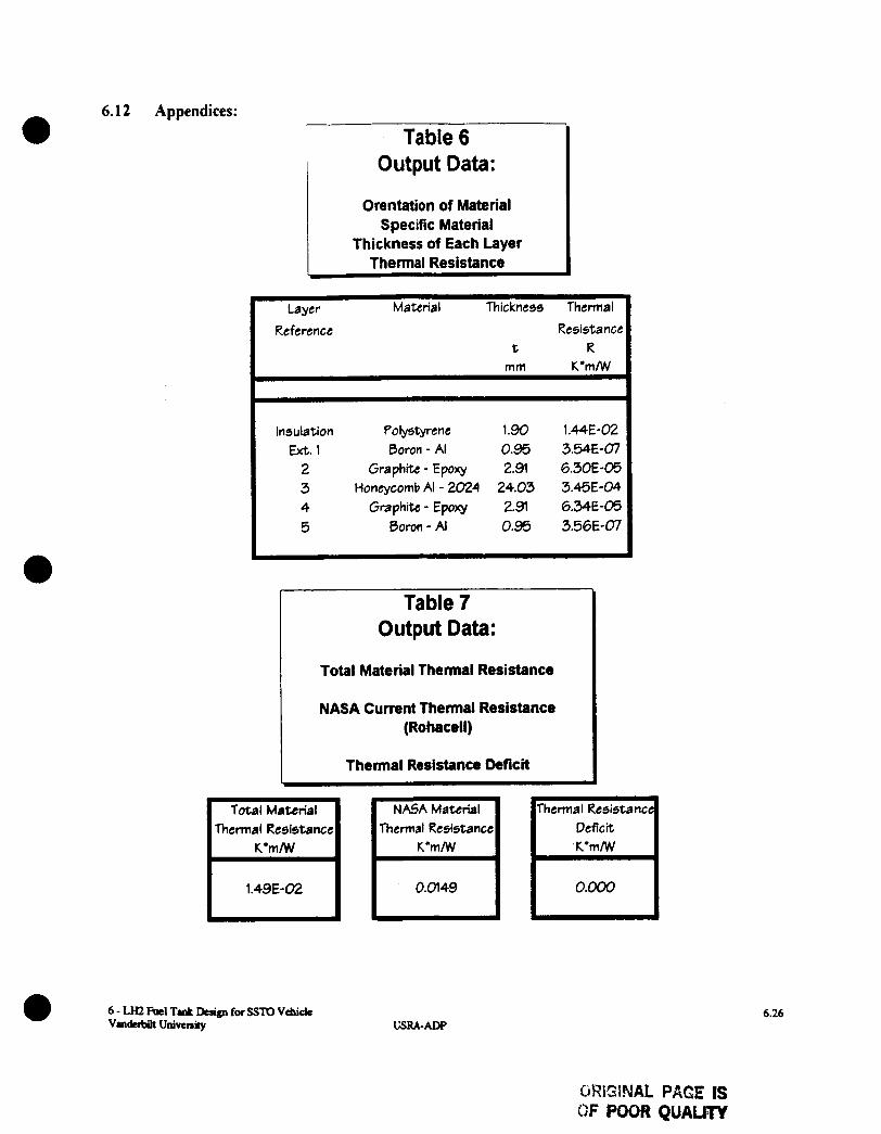
6.1 2 Appendices:
Table 6 0 ut pu t Data :
a Orentation of Material
Specific Material Thickness of Each Layer
Thermal Resistance
Reference Resistance t R
mm K ' m N 1
I Layer Material Thickness Thermal
Insulation Polystyrene 1.90 1.44E-02 Ext. 1 Boron - AI 0.95 3.54€-07
2 Graphite - Epoxy 2.91 6.30E-05 3 Honeycomb AI - 2024 24.03 3.4%-04 4 Graphite - Epoxy 2.91 6.34E-05 5 Boron - AI 0.95 3.56E-07
Table 7 0 ut put Data:
Total Material Thermal Resistance
NASA Current Thermal Resistance (Rohacell)
Thermal Resistance Deficit
Total Material Thermal Resistance H 1.49E-02
NASA Material Thermal Resistancc
6.26 USRA-ADP
OWISINAL PAGE IS OF POOR QUALiTY
6.12 Appendices:
I Table 8 Output Data:
A
Volume of Tank's Applied Insulation
Tank Tank Tank Insulation Insulation Insulation
Mass Volume Density Kc? m"3 Kg/mA3
32 3.84E+Ol 1.20E+00
roA2 - rin2 Length Volume
I 0.0160 I 1*20E+00 I I
Table 9 Output Data:
Mass of Tank's Insulation
(Polystyrene)
6 - LH2 Fuel Tvllr &sign for SSTO Vehide Vnderbilt Univenky USRA-ADP
6.27
6.1 2 Appendices:
e
I
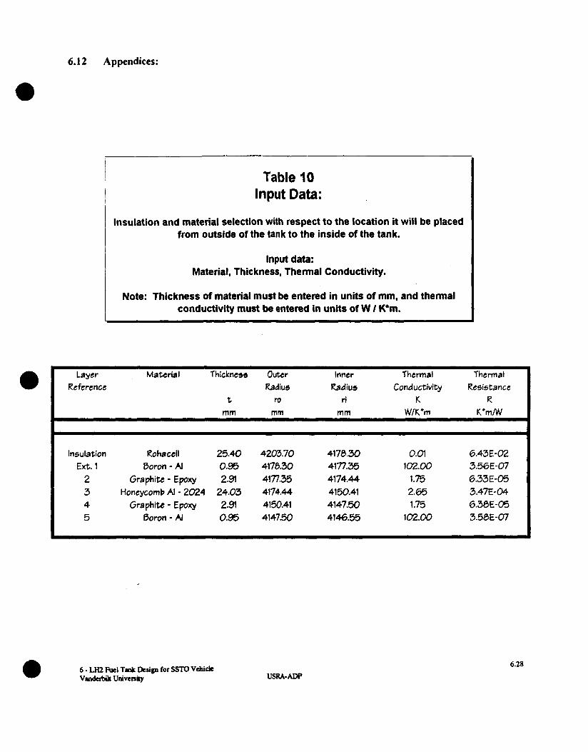
Table I O Input Data:
Insulation and material selection with respect to the location it will be placed from outside of the tank to the inside of the tank.
Input data: Material, Thickness, Thermal Conductivity.
Note: Thickness of material must be entered in units of mm, and thermal conductivity must be entered in units of W I K*m.
Layer Material Thickness Outer Inner Thermal Thermal Reference Radius Radius Conductivity Resistance
t ro ri K R mrn mrn mrn WIK'rn K ' m N
Insulation Rohacell 25.40 4203.70 4170.30 0.01 6.43E-02 Ext. 1 Boron - Al 0.95 4178.30 4171.35 102.00 3.56E-07 2 Graphite - Epoxy 2.91 4171.35 4174.44 1.75 6.33E-05 3 Honeycomb AI - 2024 24.03 4174.44 4150.41 2.65 3.47E-04 4 Graphite - Epoxy 2.91 4150.41 4147.50 1.75 6.30E-05 5 Boron - Al 0.95 4147.50 4146.55 102.00 3.50E-07
USRA-ADP 6.28

6.12 Appendices:
I Table 12 Output Data:
Total Material Thermal Resistance
NASA Current Thermal Resistance (Rohacell)
Thermal Resistance Deficit
T a b l e 11 Output Data:
Orentation of Material Specific Material
Thickness of Each Layer Thermal Resistance
Layer Matcrial Thickness Thermal
Reference Resistance t R
mm K ' m N
Insula tion Rohacell 25.40 6.43E-02 Ext. 1 Boron - AI 0.95 3.56E-07
2 Graphite - Epoxy 2.91 6.33E-05 3 Honeycomb AI - 2024 24.03 3.47E-04 4 Graph& - Epoxy 2.3 6.38E-05 5 Boron - AI 0.95 3.50E-07
NASA Material Thermal Resistance
K'mMI
I 0.0149
Thermal Resistance
6.40E-02
hemal Resistanc Deficit
6 - LH2 Aul TU* D c r i p for SSTO Vehide Vvldcrbilt Univenity
6.29 USRA-ADP
6.1 2 Appendices:
L
Tank Tank r o ~ 2 - r - i ~ ’ Length Volume
Table 13 Output Data:
Volume of Tank’s Applied Insulation
H 24.20 1.62E+Ol 0.2129
Table 14 Output Data:
Mass of Tank’s Insulation (Rohacell)
Tank Tank Tank Insulation Insulation Insulation
Mass Volume Density Ks rn ̂ 3 KglmA3
8.30€+02 1.62E+Ol 51.3
6 - LH2 Fuel Tvllt Design for SSTO Vehicle vmdem U N v e n ~ USRA-ADP
6.30
6.1 2 Appendices:
C u t -away Port i on o f T a n k Con f i g u r a t i 011
Outside l a 1 1 Bone ycomb loside l a l l
Insrlrtior Organic Matrix Bonejcoab (EPSI ( Cr-Ep I ( A I 20241
ietrl Matrix ( AI-9 I
6 - LH2 Fuci Tvlt D e r i p for SSTO Vchide e V a n M Univenily 6.3 1
USRA-ADP