level .. · mk 16 mod 0 uba techeval report july 1980 by: m. j. harwood ... a review of the manual...
TRANSCRIPT
LEVEL .. '4
NAVY EXPERIMENTAL DIVING UNIT
DTIC-' S EL EtC
NOV 2 4 1980
B
-J
L--
I DISTRIBUTION STATEMENT A
Approved for public release;Distribution Unlimited 80 10 15 012

DEPARTMENT OF THE NAVYNAVY EXPERIMENTAL DIVING UNIT
PANAMA CITY. FLORIDA 32407 IN FtUPLN "RftR TO!
iI
NAVY EXPERIMENTAL DIVING UNIT
REPORT NO. 14-80
MK 16 MOD 0 UBATECHEVAL REPORT
JULY 1980
By: M. J. Harwood
Approved for public release; distribution unlimited.
DTICS-EECTFENOV 2 4 1980
B
Submitted: Reviewed: Approved:
M. J. HARWOOD D. M. HAMILTON, IV R. A. BORNHOLDTLCDR, Royal Navy J--DR, U. S. Navy CDR, U. S. NavyMK 16 MOD 0 UBA Senior Projects Officer Commanding OfficerProject Officer
I/

UNCLASSIFIED O HSPG W~nIaeEtrd _________________
SECURITY CLASSIFICATIONOFTIPAE(abeentrd
RED ENSRUCIONSVE
REOR DOUMNATO 6. BFORE CGOMPLTING FORM
2. ~ ~ ~ ~ 1 GRV CE IJNJ.ANTA NUMBERI
Na1vy O Experi ental e Divi thig Uparts'Fta
anamaF City FlRrid 3240
9I. CERONROLING ORGAICAIO NAME AND ADDRESS 1. PORMEEET RJCTS
14. MONITORING AGENCY NAME & en' frontf Controlinirg Office) ill. SECURITY CLASS. (of this report)
AOGAE~~~eFUNCLASSIFIED
IS&. OECL ASSI F1CATION/ DOWN GRADINGSCHEDULE
16. DISTRIBUTION STATEMENT (of this Report)
Approved f or public release; distribution unlimited.
17. DISTRIBUTION STATEMENT (ol the abstract entered In Block 20, it different fromt Report)
I6. SUPPLEMENTARY NOTES
I9. KEY WORDS (Conttntae on reverse side If neceecery and Identify by block number)
MKC 16 MOD 0 UBA TECHEVALIAI 20. ABSTRACT (Continue an reverse side it necessary and Identify by ýlock number)
The Technical Evaluation (TECHEVAL) oý the MK 16 MOD 0 UnderwaterBreathing Apparatus (UBA) was conducted by k~he Navy Experimental DivingUnit (NEDU) from 5 M~ay through 13 June 1980. ý'Specific objectivesiwero toachieve 100 hours bottom time at depths to 150 FSW and to verify Mean Time
Between Failures (MTBF) and Mean Time To Repair (MTTR). The results of the
TECHEVAL revealed many deficiencies which should be coirected and tested
prior to 0PNVAL.
DD I Am, 1473 EDITION O1 'NOV6GS 15 OBSOLETE UNCLASSIFIEDS/K 01 02-0 4* 660 1I
SECURITY CLASSIFICATION OF THIS PAGE (hnDt

ABSTRACT
The Technical Evaluation (TECHEVAL) of the MK 16 MOD 0 UnderwaterBreathing Apparatus (UBA) was conducted by the Navy Experimental DivingUnit (NEDU) from 5 May through 13 June 1980. Specific objectives were toachieve 100 hours bottom time at depths to 150 FSW and to verify Mean TimeBetween Failures (MTBF) and Mean Time To Repair (MTTR). The results of theTECHEVAL revealed many deficiencies which should be corrected and testedprior to OPEVAL.
Accession For
NTIS GRA&IDTIC TAB ElUnannounced El
Enclosures I thru 5, NEDU Test Plan 80-14 ___iodated 30 April 1980 is Enclosure 1 for the en-tire report per Lt. Harper, NEDU By
Distribution/
Availability CodesAvail and/or
Diý;t Special

, ,~ 71 - , ,- . 7ý
TABLE OF CONTENTS PAGE NUMBER
Abstract jTable of Contents ii
Glossary iii
References v
Enclosures vi
Introduction 1
Figure I - MK 16 MOD 0 Underwater Breathing Apparatus 2
Figure 2 - Pneumatics Schedule 3
Summary of Diving Achieved 4
Summary of Objectives Achieved 4
Primary and Secondary Battery Usage 5
Recommended Engineering Changes 5
Discussion 5
li
4*

i. -
GLOSSARY
DA Development Agency
DT III Development Testing Phase 3
ECP Engineering Change Proposal
EOD E~xplosive ordnance Disposal
EOD Det Explosive Ordnance Disposal Detachment
FFM Full Face Mask
FSW Feet Sea Water
HP High Pressure
ID Identification
ibs Pounds Weight
LCD Liquid Crystal Display
LED Light Emitting Diode
LIS Low Influence Signature
mA milli ampere
MTBF Mean Time Between Failure
MTTR Mean Time To Repair
NEDU Navy Experimental Diving Unit
NAVEODFAC Naval Explosive Ordnance Facility
NTP Navy Training Plan
02 Oxygen
O&M Operation and Maintenance
OPEVAL Operational Evaluation
PMS Preventative Maintenance Schedule
P02 Partial Pressure of Oxygen
PPM Pre-Production Model
iii
2' !
TEMP Test and Evaluation Master Plan
UBA Underwater Breathing Apparatus
VDC Volts Direct Current
iv
REFERENCES
1. TEMP #765-1 dtd 17 March 1980 (DRAFT)
2. NEDU Itr EDU:CAB:jt 3948 Serial 109 dtd 24 March 19B0
I'!
tvL
1.
In, _ ... .. .. ... .-. • -- •- • . . .... + - • : , . . .. i
- k .....
ENCLOSURES
1. NEDU TEST PLAN NUMBER 80-14 DTD 30 APRIL 1980
2. MK 16 MOD 0 UBA - NUMBER OF DIVES, DEPTHS AND DURATION
3. MK 16 MOD 0 UBA - MTBF DURING TECHEVAL
4. MK 16 MOD 0 UBA SPARE PARTS OUTFIT - PROPOSED LIST
5. MK 16 MOD 0 UBA - SPECIAL TOOL REQUIREMENTS
6. MK 16 MOD 0 UBA - TRAINING COURSE PLAN AND LEARNING OBJECTIVS - NEDU COMMENTS
7. HK 16 MOD 0 UBA - ENGINEERING CHANGE PROPOSALS (ECP'S)
8. MK 16 MOD 0 UBA - PRE-PRODUCTION MODEL (PPM) CONFIGURATION DIFFERENCES
9. MK 16 MOD 0 UBA - ADDITIONAL SPARE PARTS TO OVERHAUL UBA'S
10. MK 16 MOD 0 UBA - SUMMARY OF PRIMARY AND SECONDARY BATTERY USAGE RATES
11. MK 16 MOD 0 UBA - PRIMARY BATTERY CHARGING STATION AND METER FOR SECONDARYBATTERY CHECK WIRING DIAGRAM AND OPERATING PROCEDURES
vi
;• • ,,L. ... . . . .. .. . .. ... .... . .. . . .. '" " • , ' -,i

I. Introduction
a. The Technical Evaluation (TECHEVAL) of the MK 16 MOD 0 Underwater BreathingApparatus (UBA) (Figure 1) was conducted by the Navy Experimental Diving Unit (NEDU)from 5 May through 13 June 1980 in accordance with reference 1.
b. The MK 16 MOD 0 UBA is a Low Influence Signature (LIS) closed-circuit,mixed-gas, constant partial pressure oxygen, underwater life support systemdeveloped to support the low magnetic and acoustic signature requirements ofExplosive Ordnance Disposal (EOD). The breathing medium is kept at a predeterminedpartial pressure of oxygen (P0 2 ) set point by use of oxygen sensors that monitor,evaluate, and control the level via a battery operated electronic module. Themajor individual components under development to support the LIS requirementconsist of a Light Emitting Diode (LED) primary display mounted in the face mask;a plastic cased, rechargeable non-magnetic battery; a solid state, semiconductor,expendahle electronics package, an LIS oxygen control valve, and a Liquid CrystalDisplay (LCD) secondary display (Figure 2).
c. The Objectives of the Technical Evaluation (TECHEVAL) were:
(1) Specific
(a) To achieve at least 100 hours bottom time at depths to 150 FSW.
(b) Verify a Mean Time Between Failure (MTBF) for a 4 hour mission of:
1. Life Support Subsystem Components - 158 hours for a 95%confidence level.
2. Mission Support - 38 hours for a 80% confidence level.
(c) Verify a Mean Time To Repair (MTTR) of 1 hour.
(2) Additional
(a) Verify the probability of achieving an Operational Availabilitysuch that two out of every three UBA MK 16 MOD O's will be available at thecommencement of a planned miqqion. (In the case of TECHEVAL this will be consideredto be prior to-each planned dive and Dive Supervisor check).
I (b) Evaluate the supportability by validating the technical adequacy,content and format of the Operations and Maintenance (O&M) Manual and PreventativeMaintenance Schedule (PMS).
(c) Evaluate the adequacy of the Interim Spare Parts Outfit to verifyit can support PMS and corrective maintenance.
Wd) Evaluate the Tool/Test Equipment provided to support turnaroundmaintenance, repairs, and PMS.
(e) Evaluate the proposed Training Course Plan and Learning Objectives.
(f) Continue evaluation of human engineering factors with specificattention to those areas found to be lacking during previous DT III tests.
S i• I il I ' 1

PRERIMARY
II
PFIGURERE
HIGH

mail ,,ESCRIPTION
1 OXYGEN STORAGEBOTTLE
2 OXYGEN BOTTLEVALVE
3 OXYGEN REGULATOR4 4 MICRON FILTER5 OXYGEN ADDITION
VALVES ELECTRONICS ASSY.7 TUBE ASSEMBLY
WELOMENT8 CHECK VALVEi9 OXYGEN MANUAL
i - -BY-PASS VALVE10 DILUENT BY-PASSI 'VALVE
- 11 DILUENT STORAGEBOTTLE
12 DILUENT REGULATOR13 4 MICRON FILTER
1 - 14 DILUENT ADDITIONVALVE
15 DIAPHRAGM" I 16 DIAPHRAGM VENT
VALVE17 DILUENT BOTTLE
VALVE18 PRIMARY DISPLAY
I 19 TO SECONDARY, , .DISPLA.Y
II
MK 16 MOO O UBAPNEUMATIC S SCHEMATIC
FIGURE 2
3

d. The TECHEVAL was conducted in accordance with NEDU Test Plan Number 80-14dated 30 April 1980 [Enclosure (1)]. The program was extended by one week in anattempt to make up time lost due to foul weather, long transit times to the divesites ane the requirement to try and meet all the reliability hours during TECHEVAL.(Reference 2, Enclosure (1) paragraph 5 refers].
2. Summary of Diving Achieved
a. 193 MK 16 MOD 0 UBA dives were made in water depths varying from 12 to150 FSW. [For full details see Enclosure (2).] The total water time was 305.5hours.
3. Summary of Objectives Achieved
a. Specific
(1) 100 hours bottom time was achieved at depths to 150 FSW [See Enclosure(2)].
(2) The MTBF for a 4 hour mission was not achieved for life supportsubsystem components or mission support as set out in paragraph l,c,(l),(b) above,This we't lie to lack of achieving the hours in the TECHEVAL time period and thenumber of reported failures. These failures are subject to review, and may or maVtnot be discounted depending on the particular failure mode. The summary of MTBFfailures is contained in Enclosure (3).
(3) The MTTR of 1 hour was achieved when spares were available. The lackof 2 complete spares outfits for the 6 MK 16 MOD 0 UBA's prevented a full assessmentof this objective. There is no reason to believe that with a full spares outfitthe MTTR of 1 hour cannot be achieved.
b. Additional
(1) The probability of achieving an Operational Availability such that twoout of every three MK 16 MOD 0 UBA's will be available at the commencement of aplanned mission was met during TECHEVAL.
(2) The evaluation of the supportability by validating the technicaladequacy, content and format of the 06M Manual and PMS was not achieved. TheDRAFT O&M Manual presented for TECHEVAL had many minor errors in the text, andthe assembly exploded view drawings and parts lists were not up to date. However,this had been expected as the O&M Manual was a first cut and had been completedprior to the configuration audit. A review of the manual took place early in theTECREVAL, and the NEDU input was forwarded direct to the software contractor andNAVEODFAC Representative. A further review of the next draft prior to OPEVAL isrecommended. The PMS, as written in the manual, requires review. This will beconducted prior to OPEVAL. P1S cards were not present for TECHEVAL, and were notexpected due to the late arrival of the O&M Manual.
(3) The Interim Spare Parts Outfit was far from complete, and no attemptwas made to evaluate its adequacy to support PMS and corrective maintenance. 2However, a best attempt at producing a Spare Parts Outfit is at Enclosure (4). tI
4
(4) The Tool/Test Equipment was not reviewed during TECHEVAL. The reviewshould take place when the PMS has been finalized. A list of tools that will beneeded to conduct Pre-Dive, Post-Dive, Trouble-Shooting and PMS should be includedin the O&M Manual.
(a) Special tools required, other than those in a normal EOD Detnon-magnetic tool kit, are included in Enclosure (5).
(b) On completion of the reliability testing of the Primary andSecondary Batteries, the electronic test equipment requirement for the MK 16 MOD 0UBA should be reviewed.
(5) The proposed Training Course Plan and Learning Objectives were reviewed.NEDU comments are included in Enclosure (6).
(6) The Human Engineering Factors Evaluation recommended changes duringDT III have been included in Enclosure (7).
4. Primary and Secondary Battery Usage
a. A major area of concern was the high usage of both the re-chargeable primarybattery and the throw-away secondary battery.
b. A summary of the battery usage is included as Enclosure (10). Both batteriesneed to be subjected to intense reliability testing. The results from the reliabilitytesting should be used to produce new guidance on charging and use. This guidancemust be available prior to OPEVAL.
5. Recommended Engineering Changes
a. As a result of the Human Engineering Factors Evaluations, DA TestDirector Observations during DT III, and constructive comments from varioussources connected with DT Ill; numerous Engineering Change Proposals (ECP's) arerecommended either before the Operational Evaluation (OPEVAL) or before production(Enclosure (7)).
b. During DT III testing, it was noted that the 6 Pre-Production Models (PPM)of the MK 16 MOD 0 UBA were not identical. The list of differences is included asEnclosure (8). These should be corrected prior to OPEVAL.
c. Prior to OPEVAL, certain parts oi PPMs 1 through 6 which had excessiveuse during TECHEVAL or are considered to be high usage items due to the presentMK 16 MOD 0 UBA design, should be made available or replaced. These are listedin Enclosure (9).
6. Discussion
a. The MK 16 MOD 0 UBA completed NEDU TECHEVAL but did not achieve the totalnumber of hours to verify the MTBF requirement. Also, many deficiencies were
identified which should be corrected prior to OPEVAL.
b. Although the number of emergent problems experienced during TECHEVAL wouldindicate that the MK 16 development had not progressed to the TECHEVAL stage, many ofthese problems would not have been identified had open-sea testing not been conducted.
5

c. Recommendation: That the changes to the HUK 16 MOD 0 UIA recomwndedby this report be completed and tested prior to OPEVAL.
..-
I!
hJ6
..... .-
DEPARTMENT OF THE NAVY
.r NAVY EXPERIMENTAL DIVING UNITPANAMA CITY, FLORIDA 391407 IN REPLY REPRk Tot
NAVY EXPERIMENTAL DIVING UNIT
TEST PLAN
Test Title: Underwater Breathing ApparatusMK 16 MOD 0 Technical Evaluation
Test Plan Number: 80-14
Date: 30 April 1980
Prepared by: / Reviewed by: Approved
SiiiM. J . HARWOOD ISON A. BARTOL01•ENLCDR, RN LCD USN CDR, USNMK 16 MOD 0 Project Operations Officer Commanding OfficerOfficer -
S-12Engineer Officer
CDR, USN
AProjets 0
er
H. H. S ~URCAPT, MC, USNSenior Medical Officer
LCDR, USNExecutive Officer
1. Introduction
a. The Underwater Breathing Apparatus (UBA) MK 16 MOD 0 is a LowInfluence Signature (LIS) closed circuit, mixed gas, constant partialpressure oxygen, underwater life support system developed to support thelow magnetic and acoustic signature requirements of Explosive OrdnanceDisposal (EOD). The breathing medium is kept at a predetermined partialpressure of oxygen (PPO2) set point by use of oxygen sensors that monitor,evaluate, and control the level via a battery operated electronic module.The major individual components under development to support the LowInfluence Signature (LIS) requirement consist of a Light Emitting Diode(LED) primary display mounted in the face mask; a plastic cased,rechargeable non-magnetic battery; a solid state, semiconductor, expendableelectronics package, an LIS oxygen control valve, and a Liquid CrystalDisplay (LCD) secondary display.
b. The Objectives of the Technical Evaluation (TECHEVAL) Test are:
(1) Specific
(a) To achieve a least 100 hours bottom time at depths to150 FSW.
(b) Verify a MTBF for a 4 hour mission of:
1. Life Support Subsystem Components - 158 hours for a95% confidence level.
2. Mission Support - 38 hours for a 80% confidence level.
(c) Verify a MTTR of 1 hour.
(2) Additional
(a) Verify the probability of achieving an OperationalAvailability such that two out of every three UBA HK 16 MOD 0's will beavailable at the commencement of a planned mission. (In the case ofTECHEVAL this will be considered to be prior to each planned dive,Dive Supervisor check).
(b) Evaluate the supportability by validating the technicaladequacy, content and format of the O&M Manual and PMS.
(c) Evaluate the adequacy of the Interim Spare Parts Outfitto verify they can support PMS and corrective maintenance.
(d) Evaluate the Tool/Test Equipment provided to supportturnaround maintenance, repairs, and PMS.
(e) Evaluate the proposed Training Course Plan and LearningObjectives.
IJlw"

(f) Continue evaluation of Human Engineering Factors withspecific attention to those areas found to be lacking during previousDT III tests.
c. The training and tests will be conducted by NEDU and will takeplace at NEDU and Key West. Personnel will be drawn from NEDU, EODGRU ONE,EODGRU TWO, and NAVSCOLEOD.
d. The NAVEODFAC will be conducting MK 16 MOD 0 swims against theMISS (Multiple Influence Sensor System) during the same period as thistest. MK 1.6 dive subjects will be provided from the NEDU training group.MK 16 logistic support, spares, tools and test equipment will be sharedand dive hours, failures, etc. achieved during the MISS swims added tothe NEDU collated figures.
2. References and Enclosures
a. References
(a) NDCP #S-1317-SW dated 19 September 1979(b) TEMP #765-1 dated 17 March 1980 (DRAFT)(c) ILSP #265-4 undated (DRAFT)(d) UBA MK 16 MOD 0 O&M Manual dated 25 April 1980 (DRAFT)(e) NTP #5-80-79 dated September 1979 Revision 3 (DRAFT)(f) Reliability Program Plan dated November 1978 (1st DRAFT)(g) Maintainability Program Plan dated November 1978 (1st DRAFT)(h) System Safety Program Plan dated January 1979 (DRAFT)(i) FMEA dated January 1979 (PROVISIONAL DRAFT)(j) Configuration Management Plan dated November 1978 (1st DRAFT)(k) NEDU letter EDU*CAB:jt 3948 Serial 109 dated 24 March 1980(1) NEDU message 241348Z MAR 80(m) NEDU message 031809Z APR 80(n) NEDU letter EDU:MJH:cz 3948 Serial 129 dated 7 April 1980(o) U. S. Navy Diving Manual(p) UBA MK 15 MOD 0 O&M Manual (NAVSEA 0994-LP-016-l010)(q) Life Preserver MK 4 O&M Manual (SS 710-AA-MMO-010/TM-LPSP/MK 4(r) PRC O&M Manual dated July 1978 as amended by NEDU (DRAFT)
b. Enclosures
(1) Daily MK 16 MOD 0 TECHEVAL Schedule(2) Test Procedure for MK 16 MOD 0 TECHEVAL(3) Decompression Tables; 0.7 ATA Constant PPO2 in N2(4) Extracts from the DRAFT PRC Manual(5) MK 16 UBA TECHEVAL Accident/Incident Procedures
3. Test Number. 80-14
4. Program
a. The TECHEVAL Training Site will be at NEDU and local Panama Cityareas. The TECHEVAL site will be Key West, Florida.
2
b. Dates are:
(1) Training - 5 to 16 May 1980(2) Travel - 17 to 18 May 1980 and 7 to 8 June 1980(3) Test - 19 May to 6 June 1980
c. Total number of working days:
(1) Training - 10
(3) Test - 15 (plus 4 spare days)
d. Number of hours to be worked each day per person: Approximately10 hours for a total of 250 hours.
5. Preliminary Arrangements
a. All necessary personnel are to be nominated by name by 28 April 1980| Iand available for duty by 5 May 1980.V
b. All equipment required for the training and testing is to beavialable for use at NEDU or Key West by 1 May 1980.
c. The following equipment will be provided from sources otherthan NEDU:
(1) Use of double-lock RCC at SPECFORSWIMSCHOOL Key West asupgraded by NEDU to NAVFAC certification standards.
(2) Small boat support from NADC Key West, NCSC EOD DETand NAVSEA via NEDU.
(3) UBA MK 16 MOD 0 equipments, spares, and tool/test setsfrom NAVEODFAC.
(4) Workshop space in the vicinity of SPECFORSWI14SCHOOL andKey West EOD DET; NADC Bldg. No. 28 Pier Area Room 657, Lab. 624Office 115, and Storage Room 880.
(5) Miscellaneous items for conducting the planned dives areto be ready by 28 May 1980 (e.g. depth gauges, descending lines,buddy lines, swim floats, MK 4 life preservers, etc.).
(6) The gas transfer system designed for use with the MY 16will be provided by NSWC/DL to NEDU by 2 May for use during this test.NEDU will also provide commercially available Haskell booster pumpsfor backup use.
(7) PRC and mating rings for double-lock RCC as at present heldby NEDU on loan from NSWC/DL.
3
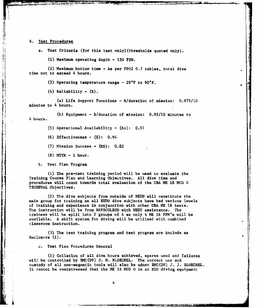
6. Test Procedures
a. Test Criteria (for this test only)(thresholds quoted only).
(1) Maximum operating depth - 150 FSW.
(2) Maximum bottom time - As per PP02 0.7 tables, total divetime not to exceed 4 hours.
(3) Operating temperature range - 29OF to 900F.
(4) Reliability - (R).
(a) Life Support Functions - R/duration of mission: 0.975/10minutes to 4 hours.
(b) Equipment - R/duration of mission: 0.95/10 minutes to4 hours.
(5) Operational Availability - (Ao): 0.9/
(6) Effectiveness - (E): 0.94
(7) Mission Success - (MS): 0.82
(8) MTTR - 1 hour.
b. Test Plan Program
(1) The pre-test training period will be used to evaluate theTraining Course Plan and Learning Objectives. All dive time andprocedures will count towards total evaluation of the UBA MK 16 MOD 0TECHEVAL Objectives.
(2) The dive subjects from outside of NEDU will constitute themain group for training as all NEDU dive subjects have had various levelsof training and experience in conjunction with other UBA MK 16 tests.The instruction will be from NAVSCOLEOD with NEDU assistance. Thetrainees will be split into 2 groups of 4 as only 4 MK 16 PPM's will beavailable. A shift system for diving will be utilized with combinedclassroom instruction.
(3) The test training program and test program are include as
Enclosure (1).
c. Test Plan Procedures General
(1) Collation of all dive hours achieved, spares used and failureswill be controlled by BMC(DV) J. H. BLOECHEL. The correct use andcustody of all non-magnetic tools will also be udner BMC(DV) J. J. BLOECHEL.It cannot be overstressed that the MK 16 MOD 0 is an EOD diving equipment
4
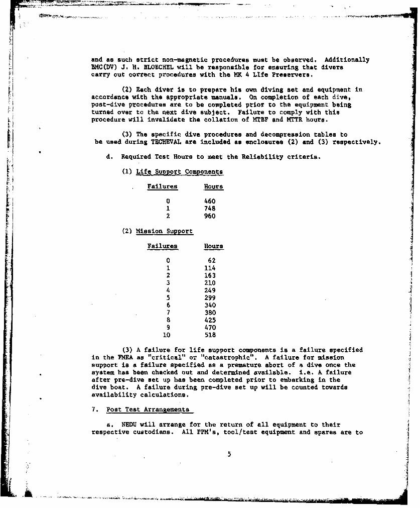
and as such strict non-magnetic procedures must be observed. AdditionallyflMC(DV) J. H. BLOECHEL will be responsible for ensuring that diverscarry out correct procedures with the MK 4 LIfe Preservers.
(2) Each diver is to prepare his own diving set and equipment inaccordance with the appropriate manuals. On completion of each dive,post-dive procedures are to be completed prior to the equipment beingturned over to the next dive subject. Failure to comply with thisprocedure will invalidate the collation of MTBF and MTTR hours.
(3) The specific dive procedures and decompression tables toI be used during TECHEVAL are included as enclosures (2) and (3) respectively.
d. Required Test Hours to meet the Reliability criteria.
(1) Life Support Components
Failures Hours
0 4601 7482 960
(2) Mission Support
Failures Hoursj
0 62
1 1142 1633 2104 2495 2996 3407 3808 4259 470
10 518
(3) A failure for life support components is a failure specifiedin the PMEA as "critical" or "catastrophic". A failure for missionsupport is a failure specified as a premature abort of a dive once the
* system has been checked out and determined available. i.e. A failureafter pre-dive set up has been completed prior to embarking in thedive boat. A failure during pre-dive set up will be counted towardsavailability calculations.
7. Post Test Arrangements
a. NEDU will arrange for the return of all equipment to theirrespective custodians. All PPM's, tool/test equipment and spares are to
5
..... ..

be returned to NAVEODFAC on completion of the test for magneticcleanliness testing.
8. Personnel
Test Direetor ,- LCDR N. J. HARWOOD, RNDive Officers - LCDR J. T. HARRISON, USN
- LCDR J. W. ENNIS, USN- LT N. G. GARON, USN
Master Diver - CPO(D) C. A. KIDMAN, RNDive Supervisors - ENC(DV) H. L. ALEXANDER, USN
- CPO(D) C. A. KIDMAN, RN- MMCS(DV) D. E. DODDS, USN
Medical Officer - LT C. G. GRAY, MC, USN; until 28 Apr- CAPT W. H. SPAUR, MC, USN; from 28 Apr
Human Factors Engineer - LTJG D. J. STYER, Sr. MSC, USNMK 16 MOD 0 Dive Subjects - MNl(DV) W. A. BRADFIELD, USN
- ABHI(DV) R. S. CROWDER, USN- LT N. G. GARON, USN- CPO(D) B. 3. FUR,4ER, RAN- GMGl(DV) A. W. PAAUWE, USN- LCDR J. W. ENNIS, USN/
LCDR J. T. HARRISON, USN- UTCS(DV) J. J. BECKER, USN- Ht(DV) J. P. BLACKSHIRE, USN-MM2(DV) C. W. WENTZEL, USN*- CWO2 W. A. BRINDLE, USN*
Medical Corpsman - HMCS(DV) T. G. HOLMES, USN; until 31 May- HMCS(DV) C. K. BLAIR, USN; from 30 May
Equipment Maintainer - BMC(DV) J. H. BLOECHEL, USN- EMCS(DV) C. P. WILKINSON, USN
Boat Maintainer - EIC(DV) C. W. CLACKLEY, USNStandby Divers & Tenders - LTJG D. J. STYER, Sr., MCS, USN
- BM2(DV) D. L. HUGHES, Jr., USN**; until31 May
- ENI(DV) J. L. DAIGLE, USN; until 31 May- BTI(DV) L. P. SIEMIET, USN; until 31 May- MMCS(DV) D. E. DODDS, USN- EMCS(DV) C. P. WILKINSON, USN- CEI(DV) M. R. ANDERSON, USN; until 31 May- BMl(DV) J. E. DEARING, USN; from 30 May- ENC(DV) R. R. SHAMBERGER, USN; until
31 May
NOTE: * indicates Advance Party to Key West and MISS swims.** indicates Advance Party to Key West.
9. Safety Rules and Precautions
a. As promulgated by the U. S. Navy Diving Manual, UBA MK 15 O&M Manual,UBA MK 16 MOD 0 O&M Manual (DRAFT), Life Preserver MK 4 O&M Manual, PRC
6

rr
O&M Manual (DRAFT) (Extracts in accordance with enclosure (4)), proceduresin accordance with enclosures (2) and (5), and decompression tables inaccordance with enclosure (3).
b. No diver is to carryout any diving for a period of at least 12 hoursbefore or after each MK 16 dive.
c. On completion of any dive requiring decompression stops, the diveris to remain with the dive team until reaching the close proximity of thetwo lock RCC. He is to remain in company with his dive buddy and within
10 minutes of the RCC for a 2 hour period after surfacing.
d. A nutritious diet is important for the long and arduous dives.
-No alcohol is to be consumed within the 24 hours preceeding a dive.
*• a. Further guidance and instructions on all dive procedures will bei in accordance with Enclosure (2), and these procedures will be exercisedduring the training period.
f. The PRC is to be available at the dive site throughout the test.Extracts from the PRC O&M Manual (DRAFT) as amended by NEDU are inaccordance with enclosure (4). This extract is to be read by all theTECHEVAL team.
10. Logistic Support Required
a. Transportation - By commercial air to NEDU (for EOD personneloutside of Panama City). As arranged by NEDU Operations Officer fromNEDU to Key West and return, except EOD personnel from outside PanamaCity who will return direct to parent commands by commercial air.
b. Boats - NADC - Swift boats.
-NCSC EOD Detachment - Boston Whaler, rubber boat.
NAVSEA provided to NEDU Monarch 23 ft.
c. Accouodation, Workshops and Office Space - Overnight boardingas booked in advance by NEDU. Workshops, NADC Bldg. No. 28, Pier AreaRoom 657, Lab 624, Storage Room 880. Office, Room 115.
d. HP Sodasorb - 20 pails at NEDU, 100 pails at Key West(transportation from NEDU 9 May)(1 pail - 37 lbs.).
a. 02 - 6 x 200 cult. bottles from NADC; 02 refilled by NADC.
11. Funding Sourcet
I a. NAVSEA Funding has been transferred to NEDU for this test.

PRIM
12. Report Production
a. NZDU wiil produce the TECHEVAL report within 30 days of completionof the test.
13. Commant./Additional Information
8
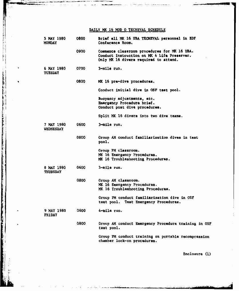
DAILY MK 16 MOD 0 TECHEVAL SCHEDULE
5 MAY 1980 0800 Brief all HK 16 URA TECHEVAL personnel in EDFMONDAY Conference Room.
0900 Commence classroom procedures for MK 16 UBA.Conduct Instruction on MK 4 Life Preserver.Only MK 16 divers required to attend.
6 MAY 1980 0700 3-mile run.
TUESDAY
0800 MK 16 pre-dive procedures.
Conduct initial dive in OSF test pool.
Buoyancy adjustments, etc.Emergency Procedure brief.Conduct post dive procedures.
Split MK 16 divers into two dive teams.
7 MAY 1980 0600 3-mile run.i WEDNESDAY
0800 Group AM conduct familiarization dives in testpool.Group PM classroom.
NK 16 Emergency Procedures.MK 16 Troubleshooting Procedures.
8 MAY 1980 0600 3-mile run.THURSDAY
0800 Group AM classroom.MK 16 Emergency Procedures.MK 16 Troubleshooting Procedures.
Group PM conduct familiarization dive in OSFtest pool. Test Emergency Procedures.
9 MAY 1980 0600 4-mile run.FRIDAY
0800 Group AM conduct Emergency Procedure training in OSFtest pool.
Group PM conduct training on portable recompressionchamber lock-on procedures.
Enclosure (1)
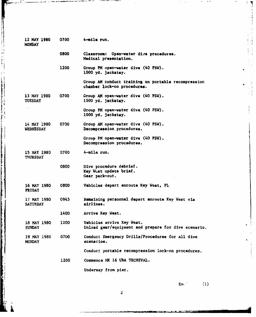
12 MAY 1980 0700 4-uile run.MONDAY
0800 Classroom: Open-water diie procedures.Medical presentation.
1200 Group PM open-water dive (40 PSW).1000 yd. Jackstay.
Group AM conduct training on portable recompressionchamber lock-on procedures.
13 MAY 1980 0700 Group AM open-water dive (40 FSW).TUESDAY 1000 yd. jackstay.
Group PM open-water dive (40 FSW).1000 yd. jackstay.
14 MAY 1980 0700 Group AM open-water dive (40 FSW).WEDNESDAY Decompression procedures.
Group PM open-water dive (40 FSW).Decompression procedures.
15 MAY 1980 0700 4-mile run.THURSDAY
0800 Dive procedure debrief.Key Wcst update brief.Gear pack-out.
16 MAY 1980 0800 Vehicles depart enroute Key West, FLFRIDAY
17 MAY 1980 0945 Remaining personnel depart enroute Key West viaSATURDAY airlines.
1400 Arrive Key West.
18 MAY 1980 1200 Vehicles arrive Key West.SUNDAY Unload gear/equipment and prepare for dive scenario.
19 MAY 1980 0700 Conduct Emergency Drills/Procedures for all dive
MONDAY scenarios.
Conduct portable recompression lock-on procedures.
1200 Commence MY. 16 UBA TECHEVAL.
Underway from pier.
En (1)
2

1300 On station. Commence Dive (40 FSW/2 HR).
1700 Depart dive site.
1800 Return to pier. Conduct post-dive procedures.
20 MAY 1980 0700 Underway from pier.TUESDAY
0800 On station. Commence Dive (40 FSW/2 HR).
1200 Depart dive site.
1300 Return to pier. Conduct post-dive procedures.
1400 Underway from pier.
1500 On station. Commence Dive (40 FSW/2 ER).
1900 Depart dive site.
2000 Return to pier. Conduct post-dive procedures.
21 May 1980 0700 Underway from pier.Wednesday
0800 On station. Commence Dive (40 FSW/4 HR).
1200 Depart dive site.
1300 Return to pier. Conduct post-dive procedures
1400 Underway from pier.
1500 On station. Commence Dive (40 FSW/4 HR).
22 May 1980 0700 Underway from pier.THURSDAY
0800 On station. Commence Dive (40 FSW/4 HR)
1200 Depart dive site.
1300 Return to pier. Conduct post-dive procedures.
1400 Underway from pier.
1500 On station. Commence Dive (40 FSW/4 HR).
1900 Depart dive site.
Enclosure (1)
3

~........ ....
2200 Return to pier. Conduct past-dive procedures.
23 May 1980 0700 Underway from pier.FRIDAY
0800 On station. Commence Dive (40 FSW/4 HR).
1200 Depart dive site.
1300 Return to pier. Conduct post-dive procedures.
Ii1400 Underway from pier.
1500 On station. Commence Dive (40 FSW/4 HR).
1900 Depart dive site.
2000 Return to pier. Conduct post-dive procedures.
24 May 1980 Gear maintenance and equipment upkeep.SATURDAY
25May 1980 Non-dive day.SNDAY
26 May 1980 0700 Underway from pier.MONDAY
0800 on station. Commence Dive (40 FSW/4 HR).
1200 depart dive site.
1300 Return to pier. Conduct post-dive procedures.
1400 Underway from pier.
1500 On station. Commence Dive (40 FSW/4 HR).
1900 Depart dive site.
2000 Return to pier. Conduct post-dive procedures.
27 May 1980 0700 Underway from pier.TUESDAY
0800 On station. Commence Dive (60 FSW/180 MIN).
1200 Depart dive site.
1300 Return to pier. Conduct post-dive procedures.
4

1400 Underway from pier.
1500 On station. Commence Dive (60 FSW/180 MIN).
1900 Depart dive site.
2000 Return to pier. Conduct post-dive procedures.
28 May 1980 0700 Underway from pier.WEDNESDAY
0800 On station. Commence Dive (60 FSW/180 MIN).
1200 Depart dive site.
1300 Return to pier. Conduct post-dive procedures.
1400 Underway from pier.
1500 On station. Commence Dive (60 FSW/180 MIN).
1900 Depart dive site.
2000 Return to pier. Conduct post-dive procedures.
29 May 1980 0700 Underway from pier.THURSDAY
0800 On station. Commence Dive (90 FSW/60 MIN).
1200 Depart dive site.
1300 Return to pier. Conduct post-dive procedures.
1400 Underway from pier.
1500 On station. Commence Dive (90 FSW/60 MIN).
1900 Depart dive site.
2000 Return to pier. Conduct post-dive procedures.
31 May 1980 Gear maintenance and equipment up-keep.SATURDAY
1 June 1980 Non-dive day.SUNDAY
2 June 1980 0700 Underway from pier.MONDAY
Enclosure (1)
5t !
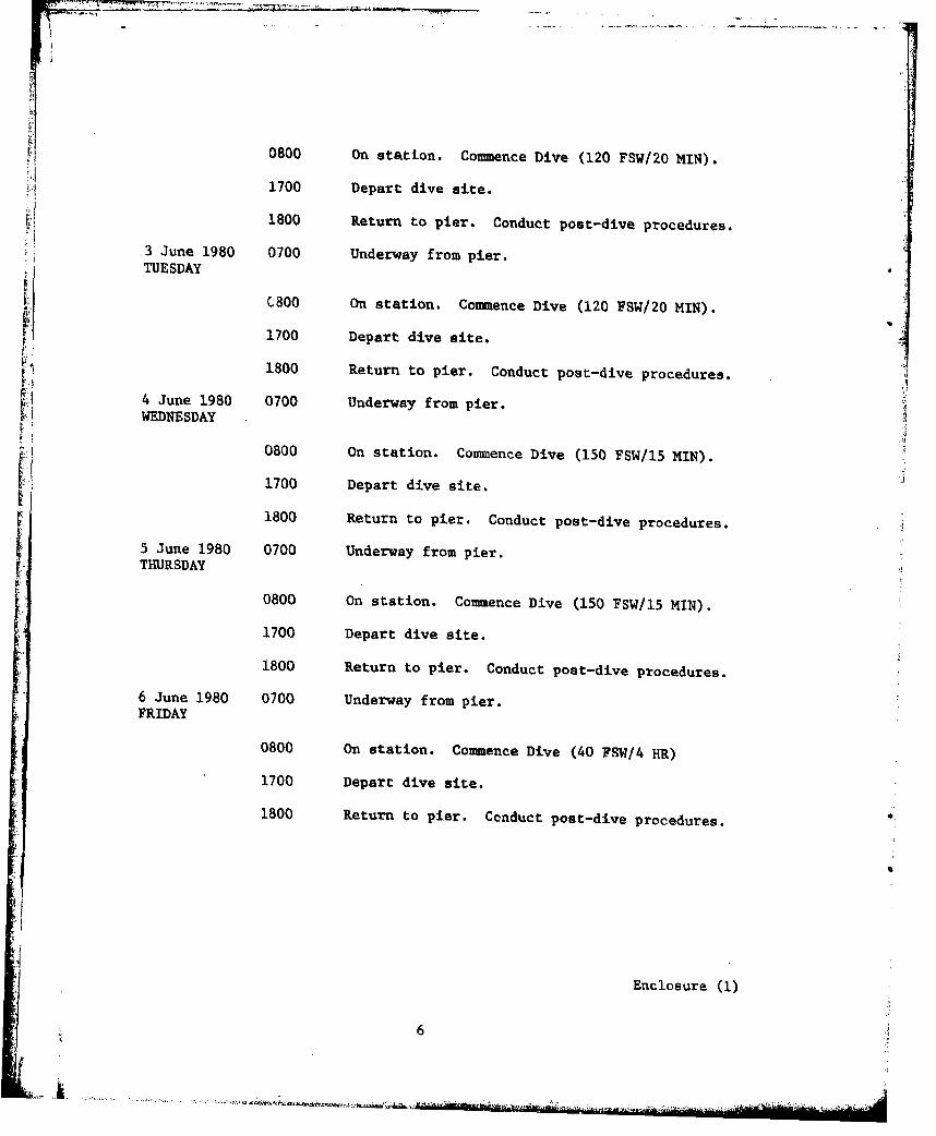
0800 On station. Commence Dive (120 FSW/20 MIlN).
11700 Depart dive aite.
L1800 Return to pier. Conduct post-dive procedures.
3 June 1980 0700 Underway from pier.TUESDAY
k C300 On station. Commence Dive (120 FSW/20 MIN).
1700 Depart dive site.
K1800 Return to pier. Conduct post-dive procedures.
4 June 1980 0700 Underway from pier.WEDNESDAY
0800 On station. Commnence Dive (150 FSW/15 MIN).H1700 Depart dive site.[1800 Return to pier. Conduct post-dive procedures.
5 June 1980 0700 Underway from pier.THURSDAY
0800 On station. Commence Dive (150 FSW/15 MIlN).
1700 Depart dive site.
1800 Return to pier. Conduct post-dive procedures.
6 June 1980 0700 Underway from pier.FRIDAY
0800 On station. Commence Dive (40 FSW/4 HR)
1700 Depart dive site.
1800 Return to pier. Conduct post-dive procedures.
Enclosure (1)
6

TEST PROCEDURE FOR MK 16 MOD 0 TECHEVAL
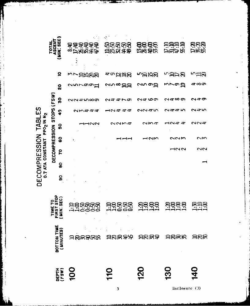
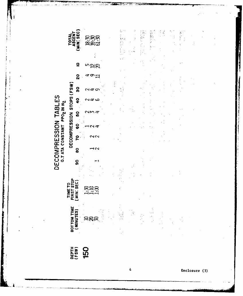
=11. Dive Procedures. The following depths and maximum bottom timeswill be used throughout the test series. All normal decompressionwill be in accordance with the U.S. Navy 0.7 ATA constant PP02 in N2tables (enclosure (3)). Emergency procedure decompression will bein accordance with enclosure (5).
Depth Bottom Time Total Ascent Time(FSW) (Minutes) (Minutes)
40 240 0-.:40 cIi60 180 38.-:0090 60 42::30 secs120 15 26::00150 15 39::30 secs
2. Specific Dive Procedures at Key West
a. Dive Days #1 and #2.
(1) On dive days #1 and #2 the dive depth will be 40 PSW withJ a 120 minute bottom time (bottom time starts when the divers leave the
surface). After pre-dive set ups two (2) sets of divers will dress up
in wet suits and M4K IV life jackets. One diver in each set will bebodily marked by a small float which will be tied off at 40 FSW (the
bothvets ofl diveso wial follow thigs) line. difvfrs somle rasonathedwt
(2) A light jacketay of 1,000 yds will have been layed and
jackstay cannot be used both sets of divers will be given a swim boardwith compass.
(3) When putting the divers in the water, the diver with thefloat line will enter the water first, the 2nd diver will enter thewater and clip up his buddy line. Both divers'will hold the clips abovethe water so that the Dive Supervisor can see that they are properlyjoined. Both divers will then check each other for leaks, if there areno leaks the Dive Supervisor will then tell the divers to leave thesurface. Two (2) minutes before the divers are to come to the surface,the dive safety boat will recover the float line and give the signal of3 pulls (standby to come up), the diver will pass this signal to hisdive buddy. The signal of 4 pulls (come up) will then be given and bothdivers will surface together. The diver with the float line will give 1pull (left bottom) when both divers leave the bottom.
(4) Both divers will come directly to the surface (at 60 FSWper min) as no decompression will be required.
Enclosure (2)
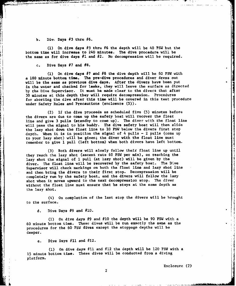
b. Divk Days #3 thru #6.
(1) On dive days #3 thru #6 the depth will be 40 FSW but thebottom time will increase to 240 minutes. The dive procedure will bethe same as for dive days #1 and #2. No decompression will be required.
C. Dive Days #7 and #8.
(1) On dive days #7 and #8 the dive depth will be 60 FSW witha 180 minute bottom time. The pre-dive procedures and diver dress outwill be the same as previous dive days. After the divers have been putin the water and checked for leaks, they will leave the surface as directedby the Dive Supervisor. It must be made clear to the divers that after30 minutes at this depth they will require decompression. Proceduresfor aborting the dive after this time will be covered in this test procedure
under Safety Rules and Precautions (enclosure (5)).
(2) If the dive proceeds as scheduled five (5) minutes beforethe divers are due to come up the safety boat will recover the floatline and give 3 pulls (standby to come up). The diver with the float line
the lazy shot down the float line to 10 FSW below the divers first stopwillh passti i osto the signal to h4 buddy. Th div saeybotulls thoen slidto your lazy shot) will be given; the diver with the float line must
r remember to give 1 pull (left bottom) when both divers have left bottom.
the rech(3) Both divers will slowly follow their float line up untilthe rechthe lazy shot (ascent rate 60 FSW per min), on reaching the
lazy shot the signal of 1 pull (at lazy shot) will be given by theJ diver. The float line will be recovered by the safety boat. The Dý..ve
Supervisor will check markings on both the float line and lazy shot lineand then bring the divers to their first stop. Decompression will becompletely run by the safety boat, and the divers will follow the lazyshot when it moves upward to the next decompression stop. The diverwithout the float line must ensure that he stays at the same depth asthe lazy shot.
(4) on completion of the last stop the divers will be broughtto the surface.
d. Dive Days #9 and #10.
(1) On dive days #9 and #10 the depth will be 90 FSW with a60 minute bottom time. These dives will be run exactly the same as theprocedures for the 60 FSW dives except the stoppage depths will bedeeper.
e. Dive Days #11 and #1l2.
(1) On dive days #1ll and #12 the depth will be 120 FSW with a15 minute bottom time. These dives will be conducted from's diving I
platform.
Enclosure (2)2
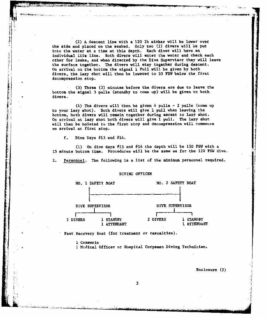
(2) A descent line with a 120 lb sinker will be lower overthe side and placed on the seabed. Only two (2) divers will be putinto the water at a time at this depth. Each diver will have anindividual life line. Both divers will enter the water and check eachother for leaks, and when directed by the Dive Supervisor they will leavethe surface together. The divers will stay together during descent.On arrival on the bottom the signal 1 Pull will be given by bothdivers, the lazy shot will then be lowered to 10 FSW below the firstdecompression stop.
(3) Three (3) minutes before the divers are due to leave thebottom the signal 3 pulls (standby to come up) will be given to bothdivers.
(4) The divers Will then be given 4 pulls - 2 pulls (come up
to your lazy shot). Both divers will give 1 pull when leaving thebottom, both divers will remain together during ascent to lazy shot.On arrival at lazy shot both divers will give 1 pull. The lazy shot
* will then be hoisted to the first stop and decompression will conmieyce
I. on arrival at first stop.
f. Dive Days #13 and #14.I
(1) On dive days #13 and #14 the depth will be 150 PSW with a15 minute bottom time. Procedures will be the same as for the 120 FSW dive.
2. Personnel. The following is a list of the minimum personnel required.
DIVING OFFICER
NO. 1 SAFETY BOAT No. 2 SAFETY BOAT
DIVE SUPERVISOR DIVE SUPERVISOR
2 DIVERS I STANDBY 2 DIVERS 1 STANDBY1 ATTENDANT 1 ATTENDANT
*Fast Recovery Boat (for treatment or casualties).
1 Coxswain
* . 1 Me'dical Officer or Hospital Corpsman Diving Technician.
1 Enclosure (2)
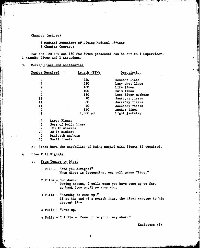
Chamber (ashore)
1 Medical Attendant o1 Diving Medical Officer1 Chamber Operator
For the 120 FSW and 150 FSW dives personnel can be cut to 1 Supervisor,1 Standby diver and 1 Attendant.
3. Marked Lines and Accessories
Number Required Length (FSW) Description
2 250 Descent lines2 120 Lazy shot lines2 180 Life lines2 100 Swim lines2 180 Lost diver markers
11 90 Jackstay risers11 60 Jackstay risers11 40 Jackstay risers
2 140 Anchor lines1 1,000 yd Light Jackstay
4 Large Floats2 Sets of buddy lines2 120 lb sinkers
20 30 lb sinkers2 Danforth anchors
15 Small floats
All lines have the capability of being marked with floats if required.
4 Line Pull Signals
a. From Tender to Diver
1 Pull - "Are you alright?"When diver is descending, one pull means "Stop."
2 Pulls - "Go down."During ascent, 2 pulls mean you have come up to far,go back down until we stop you.
3 Pulls - "Standby to come up."If at the end of a search line, the diver returns to hisdescent line.
4 Pulls - "Come up."
4 Pulls - 2 Pulls - "Come up to your lazy *hot."
Enclosure (2)
4
b. From Diver to Tender
I Pull - "I am airight"l or "I am on the bottom."
"I am at my lazy shot" or "I am at my descent line."
2 Pulls - "Lower" or "Give me slack."
3 Pulls - "Take up my slack."
4 Pulls - "I want to come up."
C. Emergency Signals
2-2-2 Pulls - "I need the assistance of the standby diver."
3-3-3 Pulls -"I am fouled but can clear myself."
j 4-4-4 Pulls -"Emergency! Recover me immediately."* (This signal does not require answering)
5. Safety Rules and Precautions. The safety of divers is of theupmost priority during this test series.* The following rules andprecautions must be adhered to.
a. Aborting a Dive. (Diver feels fatigued but is not in anemergency situation.) Diver will give one pull to call attention, thesafety boat will then recover the marker and answer the signal. Thediver will then give 4 pulls (I want to come up) before the dive safetyboat answers, the Dive Supervisor will check the divers time and ifdecompression is required the lazy shot will be lowered and the signalof 4 pulls - 2 pulls will be given to the diver. If no decompression isrequired the signal will be answered by 4 pulls (come up) and the diverswill return to the surface.
b. Divers Become Unbuddied and Lose Each Other. Both divers inthe event of losing sight of each other will surface immediately. Referto enclosure (5) for handling of divers after surfacing.
C. Diver's UBA Becomes Defective at Depth
(1) Complete loss of gas: At dive depths of 120 FSW and*150 PSW a SCUBA bottle filled with air will be stopped on the descent* line approximately 10 FSW from the bottom. Procedure for the use of
the SCUBA bottle will be in accordance with enclosure (5).
(2) 02 add valve remains open - secure 02 bottle and returnto the surface using M4K 16 Mod 0 emergency procedure for this failure mode.
Enclosure (2)
5
d. A halo will be available for emergency use if the situationrequires rapid reaction that cannot be carried out by one of the diveboats.
e. A standby diver on SCUBA will be in the imediate vicinityduring jackstay swims, one for each set of divers.
f. A standby diver in a MK-15 will be available on immediatenotice during 120 FSW and 150 FSW dives.
g. If for some reason the dive marker float becomes detached froma dive pair they will be called up by either Hydrophone or a soundsignal.
I"i
" ~Enclosure (2)
A7I6
I -°
•,ova
DECOMPRESSION TABLES
0.7 ATA CONSTANT PPO2 I N2 2
Enclosure (3)

LI z w.__
uj~ v8 c 8RE88
UiC
'NCr
CL
0
LU--
U.
0-
0jo 0
1 Enclosure (3)

2 w
0 CN.'4 :r1" C4 N t#Lt L0O 0O C"( ýg -rL O0ýC
C-v. 0 tI'-C C t 4N-1 3-C4 -r - L D 00 w J-I :I UNt.0 00 a10~
4z (ccl~K4
0' 1J
0
C; 0
00
2 Enclosure (3)
w to
IL*OR
LJL t% m "L WR ý C-4CJLntm re CIm
0 C%-V -Jt C% JN'-J.? rN-IC'4-TU CNCN.~n
LJ 0
o-0
CL-
o oQW
0a0
:E0 0 00
3- Vnlour (3) C=C)'1r- - DC: D-
Aw0)
4* z 00~
~ to
<t -. C nZ
a- 0
CO
z U))
4) Enlsr (3

L..
r7
"EXTRACTS FROM THE DRAFT PRC MANUAL
Enclosure (4)
6--
IL C06-
U
UEnclosure (4)

CHAPTER 1
GENERAL INFORMATION
1.0 INTRODUCTION
The Portable Recompression Chamber (PRC) is a one man hyperbaric
k.system designed for providing immediate recompression treatment to divers
suffering from decompression sickness or gas embolism. It is to be deployed
to remote dive sites where -recompression treatment can be administered within
five minutes to a diver shoving symptoms of these pressure-related injuries.I
The PRC can also serve as a means of transporting a stricken diver, whileA
undergoing recompression treatment, to a larger hyperbaric facility for more
definitive treatment and care.
rThe PRC is not intended as a substitute for double-lock recompression
chambers. The PRC serves as an emergency chamber at sites where double-lock
K chambers are not immediately available.
1.1 SCOPE OF MANUAL
This manual describes the purpose, limitations, treatment procedures,
operation, planning, maintenance and components of the U.S. Navy's Portable
Recompression Chamber. The certification procedures for personnel are
included in the Personnel Qualification Schedule (PQS).
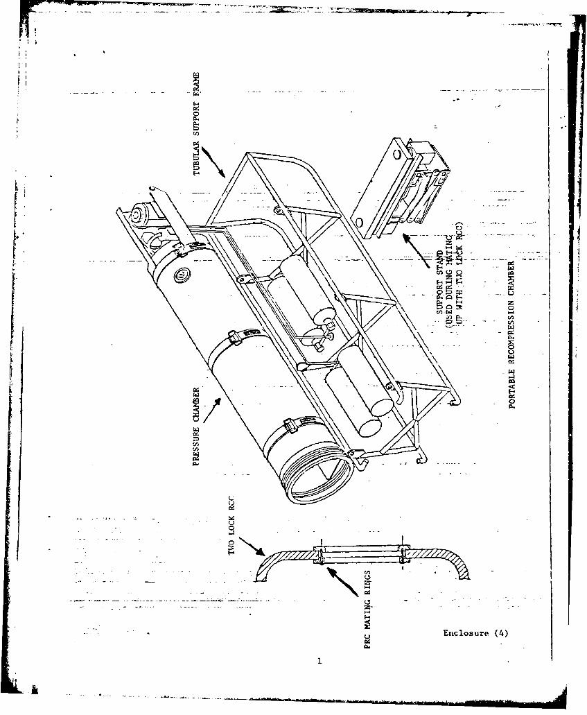
1.2 DESCRIPTION
The PRC is 106 inches long and weighs 350 pounds. It consists of a
one-man single-lock pressure chamber with recirculating, semi-closed-circuit
Enclosure (4)
2

life support system and a communication system. The chamber and piping
are mounted on a tubular support frame that serves as a stand and as a
means to facilitate transportation. A series of quick release pins hold
the chamber to the support frame. By removing the support frame, the PRC
can be passed through a circular opening of 23 3/4 inches in diameter such
as the torpedo hatch if a submarine. The PRC has a design working pressure
of 73.5 psig (165 Feet of Sea Water - FSW); however, the maximum normal
operating pressure is 44.5 psig to effect treatment at depths equivalent
to 100 FSW.
The PRC can be operated in an open-circuit or semi-closed circuit
mode if operation. The open-circuit mode is a single-pass system in which
two (2) actual cubic feet per minute* (acfm) of fresh air are metered into
the chamber, ducted to the patient, and then vented. The semi-closed circuit
mode uses approximately .5 standard cubic feet per minute (scfm) of incoming
fresh air to recirculate the breathed air, through a CO2 scrubber, by means
of an air ejector that is designed to recirculate at least two (2) acfm of
air to the patient at any operating depth. For both modes, compressed air
is supplied from twin SCUBA tanks.
A mating adapter system is included with each PRC. This adapter
system is used to mate the PRC to a Navy double lock aluminum recompression
chamber such that a patient can be transferred under pressure without
interrupting the treatment schedule.
*acfm - scfm x depth in atmospheres
Enclosure (4)
k.
CHAPTER 2
OPERATIONS
2.1 INTRODUCTION
This chapter provides condensed information for the diagnosis,
recompression treatment, and transportation of decompression sickness and
gas embolization casualties. The U.S. Navy Diving Manual, Volume I,
contains more complete information. This chapter also provides detailed
information for operational planning and operation of the PRC.
The PRC is intended to provide definitive initial treatment and
may serve to transport the injured diver, while undergoing treatment, to
a larger recompression chamber. A mating adapter system is included in
order to effect transfer upon arrival at the treatment facility. An
alternative surfacing and transfer procedure is provided. A rapid and well
throught-out transportation plan is extremely important when the PRC is
employed.
Treatment in the Portable Recompression Chamber is severely dis-
advantaged because of it being a small, single-lock, one-man system laLking
oxygen treatment capability. The advantage of the PRC is its portability
to remote dive sites for operations not supported by larger surface craft.
The compromised treatment mode can only be overcome by immediate, on-site
recompression treatment. If the PRC is not at the dive site, or if
treatment is delayed more than minutes, a poor outcome can be expected.
Therefore, the PRC should be positioned so that an injured diver can be
brought to the chamber within 5 minutes of surfacing.
L Enclosure (4)t4
Because of lack of oxygen treatment and inability to gain access
to the injured diver once pressurized, the usable treatment modes are
limited and all diving accidents will be treated with the PRC Treatment
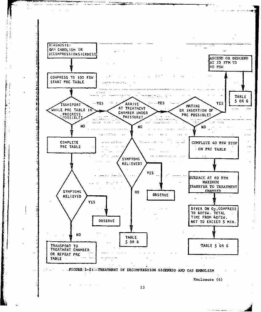
Table (Table 2-1). Figure 2-1, "Diagnosis of Decompression Sickness and
Gas Embolism" and Figure 2-2, "Treatment of Decompression Sickness and Gas
Embolism" provide guidelines for management of diving casualties with the PRC.
2.2 TREATMENT PROCEDURES
V Actions in each case, in 'he order of priority, usually are: first
aid (assure clear airway, restore breathing, assure heart function, and
stop massive bleeding); examination; diagnosis; and treatment in accordance
with the PRC Treatment Table.
required, the following step-by-step procedures will be followed:A
a. Clean, disrobe, and dress the patient for the ambient
temperature. Care must be taken not to introduce any materials into the
PRC which would contaminate the atmosphere or cause a fire hazard.
b. Always place the patient in the PRC head first and secure
with straps. The supine or prone position should be utilized as directed
by the patient's condition at the time of recompression. For example, if
vomiting is likely, the chest-down position is favored.
c. Always start treatment on the PRC Treatment Table for all cases
of gas embolism and decompression sickness. Treatment tables longer than
the PRC schedule are not to be initiate4 even if the patient is deteriorating.
Enclosure (4)
5
d. Commence recompression as rapidly as possible. DO NOT DELAY
TREATMENT BECAUSE OF A COMUNICATION MALFUNCTION.
e. The PRC Table is to be completed and the patient removed from
the PRC, even if relief is not complete or if there is recurrence during
t'eatment.
f. At the end of the PRC Treatment Table, if transfer has not
been effected, the patient must be removed, hydrated, encouraged to urinate,
and re-evaluated. A repeat PRC Table then may be warranted in cases with
residual symptoms. In addition, recurrence during treatment or following
treatment may be treated with a repeat PRC Table.
g. Observe patient for 12 hours aft';r treatment for recurrence
of symptoms.
EMF- .NCY CONSULTATION IS AVAILABLE ON 24 HOUR CALL AT THE NAVY
EXPERIMENTAL DIVING UNIT, PANAMA CITY, FLORIDA 32407. TELEPHONE AUTOVON
436-4351 OR COMMERCIAL (904) 234-4351.
2.3 TRANSPORTATION
The patient Is to be transported in the PRC, while undergoing
treatn* _, .o a *L..: treatment chamber only if transportation will not
interfere with the proper administration of the Treatment Table. Con-
ducting the PRC Table treatment has first priority. Transportation to
a larger treatment r;.aber enables the casualty to be treated with the more
effective Table 5 or 6 of the U.S. Navy Diving Manual, and allows retreat-
ment on Table 5 or 6 if relief is not complete with the PRC Table.
Enclosure (4)
6
m--
2.4 PATIENT
A patient may be transferred from the PRC to a larger treatment
chamber by mating, by insertion, or by decompression, transfer and
recompression. Insertion or mating are the preferred methods of transfer
because depressurization is not required.
2.4.1 Mating
By utilizing the mating adapter system, (see paragraph 2-13) the
PRC can be mated to the standard Navy aluminum double lock recompression
chamber. After mating, compress or decompress, whichever is appropriate,
to 60 FSW and transfer patient to the double lock chamber. Treat in
accordance with Table 5 or 6.
2.4.2 Insertion
Tranfer by insertion requires that the treatment chamber be of
sufficient size to accept the entire PRC and allow removal of the patient
from the PRC. Once the PRC is inside the treatment chamber, compress the
treatment: chamber and compress or decompress the PRC, whichever is appropriate,
to 60 FSW and transfer the patient. Treat in accordance with Table 5 or 6.
2.4.3 Decompression - Transfer - Recompression
If mating or insertion of the PRC is NOT possible, complete the
40 FSW stop in the PRC. Decompression and recompression procedures, as
follows, are to be completed in 5 minutes or less:
a. Surface no faster than 60 feet/minute.
b. Transfer patient to larger chamber.
Enclosure (4)
7

c. Compress to 60 FSW in the larger chamber, breathing 0 2 from
the surface.
d. Treat with Table 5 or 6. A repeat treatment in accordance
with Table 5 or 6 may be warranted in cases with residual symptoms.
2.5 USE OF PRC IN OMITTE.D DECOMPRESSION
Certain emergencies may interrupt or prevent specified decompression.
Blow-up, exhausted air supply, bodily injury and similar situ~ations constitute
such emergencies. If the diver shows any signs of decompression sickness
or gas embolism, immediate treatment using the PRC Table is essentioL. Even
if the diver shows no symptoms of decompression sickness, ocri'Jtted d~ccompz~ession
must be made up !ai some manner to avert later difficulty.
The Surface Decompression Table Using Air may be used in the PRC,
to make up omitted decompression, only if the emergency surface interval
occurs at such a time that water stops are not required or have already
been completed.
When the conditions which permit the use of the Surface Decompression
Table Using Air are NOT fulfilled, the diver's decompression has been com-
promised. Special care must be taken to detect signs of decompression sick-
ness, regardless of what action is initiated. The diver must be returned
to pressure as soon as possible and the PRC Table completed. If the diver
can be transported while undergoing the PRC Table and transferred to a
double lock chamber, treatment may be completed using Table 5.
Enclosure (4)
8
2.6 OTHER USES O THE PRC
The PRC is for immediate, emergency treatment of decompression
sickness and gas embolism at diving sites where a Navy double lock
recompression chamber is not available. The PRC also provides capability
to transport the patient while he is undergoing recompression treatment.
The PRC is not to be used for surface decompression, pressure tests,
or indoctrination dives.
K The PRC may be used for the training and certification of the PRC
chamber operators. A 60 FSW for 10 min with stops of 5 min at 40, 30, 20,
and 10 ft may be used for training and familiarization purposes.
The Diving Manual requirement to have a chamber on site for surface-
supplied air or helium-oxygen diving deeper than 170 feet cannot be fulfilled
by the PRC. The YRC does meet the requirements for a chamber on site for
scuba and mixed gas scuba diving.
2.7 ABORT PROCEDURES
In an emergency, the PRC Table may be aborted during compression
or during the initial 25 minutes of bottom time by using the no-decompression
tables of the Standard Air Tables. An emergency abort may worsen decompression
sickness. Recompression and PRC Table treatment should follow immediately
if the cause of the emergency can be corrected.
Figure 2-1, "Diagnosis of Decompression Sickness and Gas Embolism"
and Figure 2-2, "Procedures for Treatment of Decompression Sickness and
Gas Embolism" will be helpful in the diagnosis of and treatment of patients.
Enclosure (4)
9
2.3 tERMAL CONSIDERATIONS
Under high environmental temperature conditions, or when placed in
direct sunlight, the PRC is subject to sufficient heat build-up to
result in heat stres.s to the diver. In addition, metabolic heat pro-
duced by the diver's body is confined to the chamber, and water vapor
from diver sweat production causes the relative humidity within the
PRC to quickly approach 100%. Air flow within the chamber is slight,
and this impairs heat loss as well. Heat build-up, which begins with
compression and may continue for the entire six-hour PRC Table, causes
increasing stress on the diver hour by hour. Physiological changes from
heat stress, including dehydration and low blood pressure, may interfere
with successful treatment of decompression sickness. For these reasons,
the PRC cannot be utilized at ambient shaded temperatures of greater
than 850F (29.SC) for six hours or 95°F (35 0 C) for two hours.
Normally, most heat loss occurs at the skin surface where heat is
transferred from deep body tissues by the flow of blood. As the heat
content of the body increases, surface skin blood vessel dilation occurs,
thereby increasing blood flow to the skin and allowing heat loss by
convection and radiation. In addition, water is deposited at the skin
surface by increased sweat gland activity and diffusion through the skin.
Evaporation of this water results in a large increase in the rate of
coolinp. Although the body can produce sweat at a high rate, evaporative
heat loss is limited by skin temperature; the difference or gradient
between water vapor pressure at the skin and in surrounding air; and
movement of air across the body surface.
Enclosure (4)
10

When the temperature within the PRC is high, evaporative-heat lops
can not compensate for the heat load. This is attributable to failure
to achieve a high perspiration rate, or to failure to achieve a high
evaporative rate. Even when the perspiration rate is high, conditions
of high relative humidity and low ventilation in the PRC seriously limit
cooling by evaporation. In addition, the maximum attainable perspiration
rate of the average person is about 30 ml or 2 ounces per minute. However,
at these rates of sweating, even with adequate consumption of salt and
water, the sweating mechanism fatigues in three to four hours, resulting
in a significant decrease in the rate of perspiration. This maximum rate
of sweating can also be limited by incomplete acclimatization of the
individual to the hot environment.
Failure to completely replace water lost by sweating may lead toI elevation of body temperature and dehydration. Overheating of the diver
initially causes generalized symptoms which may be confused with symptoms
caused by the diving accident, and may not be recognized as being related
to the effects of-heat. Presenting symptoms of heat exhaustion may
include headache, dizziness, fainting, confusion, incoordination, visual
disturbances, vomiting, and profound weakness. The skin is usually moist
and clammy, and the pulse is weak and rapid. Progression of s~mptoms with
failure of temperature regulation results in heat stroke, which is
characterized by increased body temperature, delerium, and hot, dry, flushed
skin with diminished or absent sweating. This is associated with a high
mortality rate.
S~uccessful treatment of decompression sickness depends upon adequate
hydration. Thirst is unreliable as an indicator of the water intake
11 Enclosure (4)
necessary to compensate for heavy sweating, and isolation of the patient
within the PRC makes it difficult to assess his overall fluid balance.
Because of these factors, warm weather PRC operations are limited by
the guidelines outlined in Section 2.8.1.
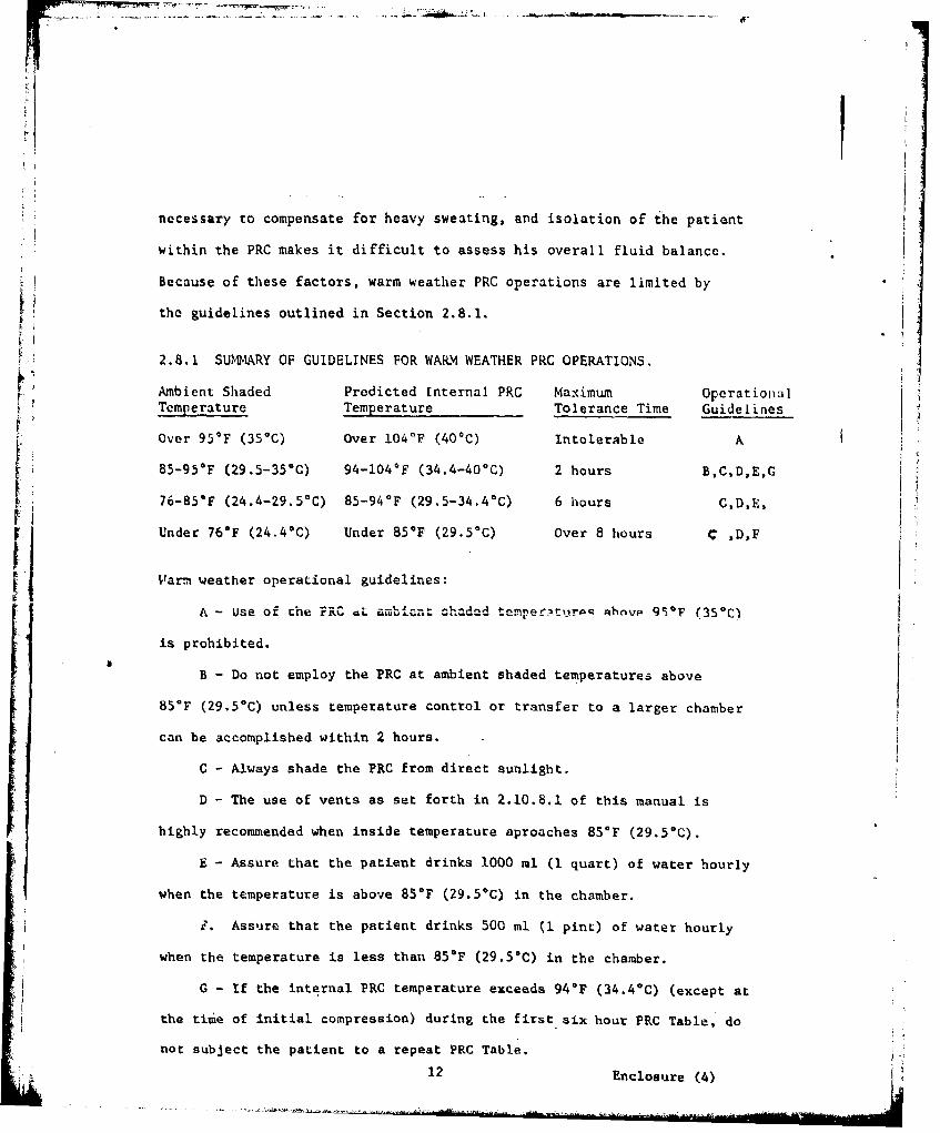
2.8.1 SURY OF GUIDELINES FOR WARM WEATHER PRC OPERATIONS.
Ambient Shaded Predicted Internal PRC Maximum Operational,Temperature Temperature Tolerance Time Guidelines
OOver 95*F (35*) over I04*F (40*C) Intolerable A
85-95*F (29.5-350C) 94-104•F (34.4-40-C) 2 hours B,C,D,E,G
76-85*F (24.4-29.5%C) 85-94°F (29.5-34.4-C) 6 hours CD,E,
Under 76OF (24.4*C) Under 85*F (29.5*C) Over 8 hours C ,D,F
Warm weather operational guidelines:
A - use of Lhe PRC oL ambinct chaded tempe t'jrpq Ahovp ()F9 (350C)
is prohibited.
B - Do not employ the PRC at ambient shaded temperatures above
85°F (29.5*C) unless temperature control or transfer to a larger chamber
can be accomplished within 2 hours.
C - Always shade the PRC from direct sunlight.
D - The use of vents as set forth in 2.10.8.1 of this manual is
highly recommended when inside temperature aproaches 85 0 F (29.50C).
E - Assure that the patient drinks 1000 ml (I quart) of water hourly
when the temperature is above 85*F (29.50C) in the chamber.
i?. Assure that the patient drinks 500 ml (1 pint) of water hourly
when the temperature is less than 85*F (29.5C) in the chamber.
G - If the internal PRC temperature exceeds 94*F (34.4°C) (except at
the time of initial compression) during the first six hour PRC Table, do
not subject the patient to a repeat PRC Table.12 Enclosure (4)
DIAGNOSIS: __________________________
GA EMBOL I S ORDECOMPRESSIONSICKNESS)
S CEND-OR DESCEND
tAT 25 FPM TO
660 FSW
COMPRESS TO 100 FSW .. --
START PRC TABLE
-RNPOTYES ARRIVE _-YES MTN --TRANSPORCTABEI AT TREATMENT OR INSERTION OF
I --- -- COMPLETE 40 FSW STOP 1
PCTBEON PRC TABLE j
SRACE AT 60 FPM
TRANSFER TO TREATMENT
IDIVER ON O2 ,COMPRESS
NOT TO EXCEED 5MIN.
HO
TRNS5R TO TABLE 5 'OR 6
TREATMENT CHAMBER IOR REPEAT PC .- __________
* TABLE ... . -.
--FIGURE: 24 i .,TREAT-NENT OF DECON1'RISStON SIMKESS -AND GAS -KMBWkISM -
Enclosure (4)
13
-- 7I
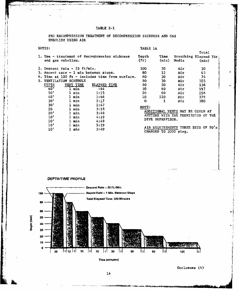
TABLE 2-1
PRC RECOMPRESSION TREATMENT OF DECOMPRESSION SICKNESS AND GASEMBOLISM USING AIR
NOTES: TABLE IATotal
1. Use - treatment of decompression sickness Depth Time Breathing Elapsed Tivrand gas embolism. (ft) (min) Media (min)
2. Descent rate - 25 ft/mmn. 100 30 Air 303. Ascent rate - i min between stops. 80 12 Air 434. Time at 100 ft - includes time from surface. 60 30 Air 745. VENTILATION SCHEDULE 50 30 Air 105hDEPTH VENT TIME ELAPSED TIME 40 30 Air 136
60' 1 mn :44 30 60 Air 19750' 1 min 1:15 20 60 Air 25840' 1 min 1:46 10 120 Air 37930' 1 min 2:17 0 1 Air 38030' 1 min 2:4720 1 min 3:18 NOTE:20 1 rn 3:18 ADDITIONAL VENTS MAY BE GIVEN AT20' 1 min 3:48 ANYTIME WITH THE PERMISSION OF THE10' 1 mfn 4 :149 DIVE SUPERVISOR.10' 1 min 4:49i0' 1 min 5:1910' 1 min 5:49 AIR REQUIREMENTS THREE SETS OF 90's
CHARGED TO 3000 pisg.
IIi
DEPTH/TIME PROFILE
Descent Rate 25 Ft./Min.
100 Ascent Rate 1 Min. Between Stops
Total Elapsed Time: 380 Minutes
60
S 40 -CL
20
30 1112111 30 1 301 30 11 60 -1 60 1l 120 Il
Time (minutes)
Enclosure (4)}
_1W
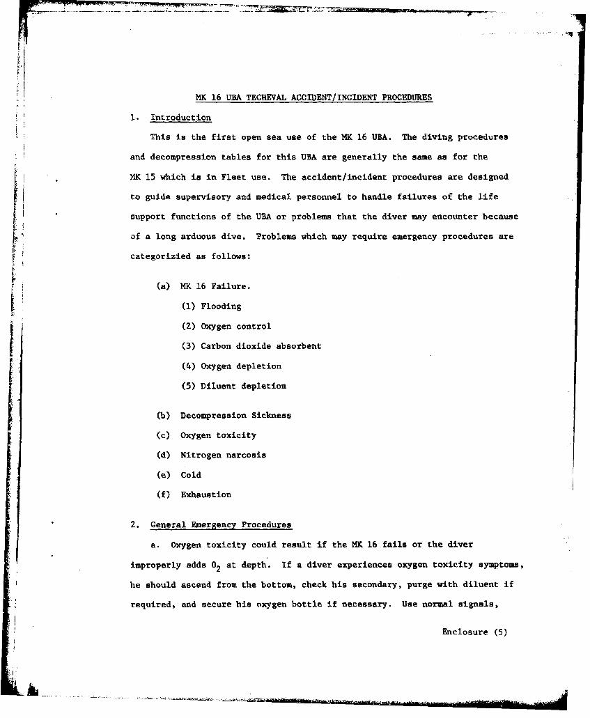
MK 16 UBA TECHEVAL ACCIDENT/INCIDENT PROCEDURES
1. Introduction
This is the first open sea use of the MK 16 UBA. The diving procedures
and decompression tables for this UBA are generally the same as for the
M4K 15 which is in Fleet use. The accident/incident procedures are designed
to guide supervisory and medical personnel to handle failures of the life
support functions of the UBA or problems that the diver may encounter because
of a long arduous dive. Problems which may require emergency procedures are
categorizied as follows:
(a) MK 16 Failure.
(1) Flooding
(2) Oxygen control
(3) Carbon dioxide absorbentF
(4) Oxygen depletion
(5) Diluent depletion
(b) Decompression Sickness
(c) Oxygen toxicity
(d) Nitrogen narcosis
(e) Cold
(f) Exhaustion
2. General Emergency Procedures
a. Oxygen toxicity could result if the MK 16 fails or the diver
improperly adds 02 at depth. If a diver experiences oxygen toxicity symptoms,
he should ascend from the bottom, check his secondary, purge with diluent if
required, and secure his oxygen bottle if necessary. Use normal signals,
Enclosure (5)
left bottom, arrived lazy shot, etc., if possible. He should switch to
SCUBA as soon as possible, and begin decompression according to procedures
using Equivalent Air Depth. If a diver experiences a convulsion, his
dive buddy should try to maintain his depth until the convulsion has
subsided and hit the diluent purge button on the rig. When the convulsion
has subsided, the buddy diver will make a controlled ascent to the surface
assisting the disabled diver.
b. Decompression sickness is improbable on the 40 FSW dives but is
possible on all the deeper dives. The diver could develop decompression
sickness during decompression. If symptoms are recognized, the diver should
signal f or assistance from the standby diver (2-2-2 pulls). The stricken
diver should attempt to complete decompression stops through the 30 FSW stop if
possible. He can then directly surface, using signals from the 30 FSW stop.
If the diver is uncertain as to the cause Of symptoms, he should switch toA
the air SCUBA.FC. The emergency procedure for any diver who arrives on the surface with
symptoms or signs of decompression sickness or air embolism is to immediately
compress the diver in the Portable Recompression Chamber (PRC), begin the
PRC Table and plan for an orderly transfer to the double lock recomnpression
chamber on shore.
d. It two divers have symptoms and require recompression, the Dive
Medical Officer or Hospital Corpsman Diving Technician is to recompress one
in the PRC and begin oxygen by mask and intravenous Ringer's lactate on the
other while proceedink to the double lock recompression chamber.
Enclosure (5)
2
e. Nitrogen narcosis may occur at 120 and 150 FSW. If narcosis persists
and seems to get worse on the bottom, the diver or divers will ascend and
give normal signals for decompression. Once the diver leaves the bottom,
symptoms shculd stop.
'f. If the diver becomes cold or exhausted before finishing the dive,
he should begin the procedures for decompression and surfacing.
3. Procedures for Specific Depth Dives
L The diver's actions for failure of the MK 16 depend upon the function
LI j ~lost. If the UBA can be manually operated, the diver is to initiate the
procedures for decompression and surfacing. Switching to air SCUBA procedures
are available for the 60, 90, 120, and 150 FSW dives.
i7
a. 40 FSW dives
The divers are buddy-line-attached swimmers towing a marker buoy.
Decompression sickness is not a consideration. If a diver has MK 16 failure
or a problem, divers are to come to the surface controlling the rate of
ascent at less than 60 ft/min if possible.
b. 60 and 90 FSW dives
(1) The divers are buddy-line-attached swimmers towing a marker
buoy. Decompression sickness is possible if a controlled ascent with
appropriate decompression stops is not followed.
(2) If there develops a MK 16 failure or a diver problem, the divers
will signal I pull on the float marker line, and when returned from topside,
four pulls to indicate leaving bottom. A Dive Supervisor, seeing the float
3 Enclosure (5)13
signal, will lower the lazy shot with SCUBA cylinder filled with air. The
diver who has a problem or a rig failure, on reaching the lazy shot, will
go on air SCUBA if necessary. Decompression can be continued on the MlK 16
if it is operable. The divers will give one pull when the diver is ready
to commence decompression on the lazy shot. The buddy diver should remain
on his MlK 16 and assist the other diver. The Dive Supervisor will control
decompression and complete all stops on the 0.7 ATA P0 in N2 Table
if the divers are on MK 16. If one diver is on air SCUBA,, both divers will
complete the 0.7 ATA Po in N Table to the first stop on the Air Equivalent2 2
Table, then complete all the appropriate Standard Air Table stops.
(3) The appropriate Air Equivalent Table will be calculated
using the 100 FSW Standard Air Table for the 90 FSW actual depth dives, and
the 60 FSW Standard Air Table for the 60 FSW actual depth dives. The bottom
time used to select the table will be all the time from leaving the surface
to the first stop on the appropriate Standard Air Table, and includes the
times of the stops on the 0.7 ATA P02 in N 2 Table.
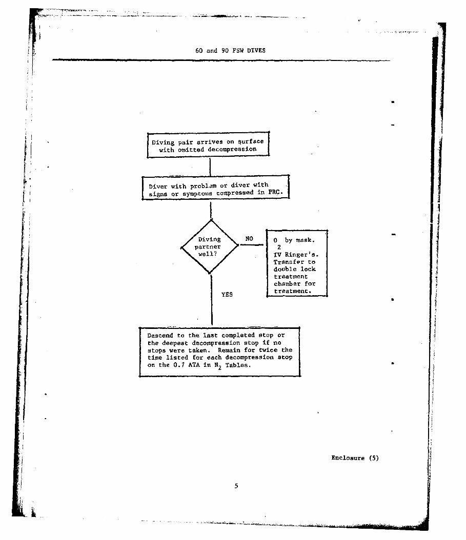
(4) If a diver surfaces because of MK 16 failure or any other
problem and has omitted any decompression, that diver will have immediate
recompression treatment in the PRC. His diving partner will also have
omitted decompression but can descend again to the depth of his last
completed stop or to the deepest decompression stop if no stops were taken.
He will remain for twice the time listed for each decompression stop on the
0.7 ATA P 0 in N 2Table. Keep the surface interval less than 5 min if2 2
possible, but the Dive Supervisor must check the diver's rig to ensure it
will sustain the diver for the extended decompression obligation. The Dive
Supervisor must be prepared to switch this diver from his M4K 16 to a standby
M4K 15 if necessary so that the added decompressiom time will not be compromised
by depletion of gas supplies or carbon dioxide absorbent failure.
Enclosure '('5)
60 and 90 FSW DIVES
1Diving pair arrives on 4urfacewith omitted decompresyion
Diver with problem or diver with
V signs or symptoms compressed in PRC.
Diving NO 0 by mask.
Spartner 2well? >IV Ringer's.
Transfer to.I double lock
treatmentchamber for
YES treatment.
Descend to the last completed stop orthe deepest decompression stop if nostops were taken. Remain for twice thetime listed for each decompression stopon the 0.7 ATA in N2 Tables.
i •i
Enclosure (5)
5
&I

c. 120 and 150 FSW
(1) The divers are tethered by separate life lines. Decompression
sickness is possible even following the appropriate decompression tables.
If one diver has a problem or a rig failure, he should ascend to the SCUBA
cylinder filled with air secured 10 PSW from the bottom. The other diver
will assist him and when ready to come up Co their lazy shot will give
a signal of 1 pull followed by four pulls. A further SCUBA cylinder will
also be secured to the lazy shot. On arrival at the lazy shot, a signal
of one pull will be given by the divers. When on their stops, the diver
on the SCUBA will give the signal of two pulls - two pulls - two pulls
(require standby divers). The standby diver will go down and check the
divers and report back to the Dive Supervisor.
(2) The partner who has no problem should remain on his MK 16,
remain on his line, and continue an orderly decompression on the 0.7 ATA
PO2 in Nitrogen Table if the diver with the problem is on air SCUBA appears
well.
(3) The diver on air SCUBA is to complete all stops on the 0.7 ATA
PO 2 in Nitrogen Table to the first stop on the Air Equivalent Table, then
complete all the appropriate standard air stops. The Air Equivalent Table
is calculated using the 130 PSW Standard Air Table for the 120 FSW actual
depth dive and the 170 PSW Standard Air Table f or the 150 PSW actual depth
dive. The bottom time used to select the table will be all the time from
leaving the surface to the first stop on the appropriate Standard Air Table.
(4) If a diver surfaces because of MK 16 failure or any other
problem and has omitted any decompression, that diver should have immediate
Enclosure (5)
6

recompression treatment in the PR.C. If his diving partner also surfaces
he will have omitted decompression but can descend again to the depth of his
last completed stop or to the deepest decompression stop If no stops were
taken. He should remain at each decompression stop twice the time listed
on the 0.7 ATA in N2Table. The surface interval will be kept to less than
5 minutes if possible. The Dive Supervisor must check the diver's rig to
ensure that it will sustain the diver for the extended decompression
obligation. The Dive Supervisor should be prepared to switch this diver
from his HK 16 to a standby M4K 15 if necessary so that added decompression time
will not be compromised by depletion of gas supplies or carbon dioxide
absorbent failure.
Enclosure (5)
7

120 AND 150 FSW DIVES
Diving pair arrives pn surfacewith omitted decompression
I Diver with problam or diver withsigns or symptoms compressed in PRC.
II
Diving NO 0 by mask.partner 2well? IV Ringer's.
Transfer todouble locktreatmentchamber for
YES treatment.
Descend to the last completed stop orthe deepest decompression stop if nostops were taken. Remain for twice thetime listed for each decompression stopon the 0.7 ATA in N2 Tables.
Enclosure (5)
!, ~8
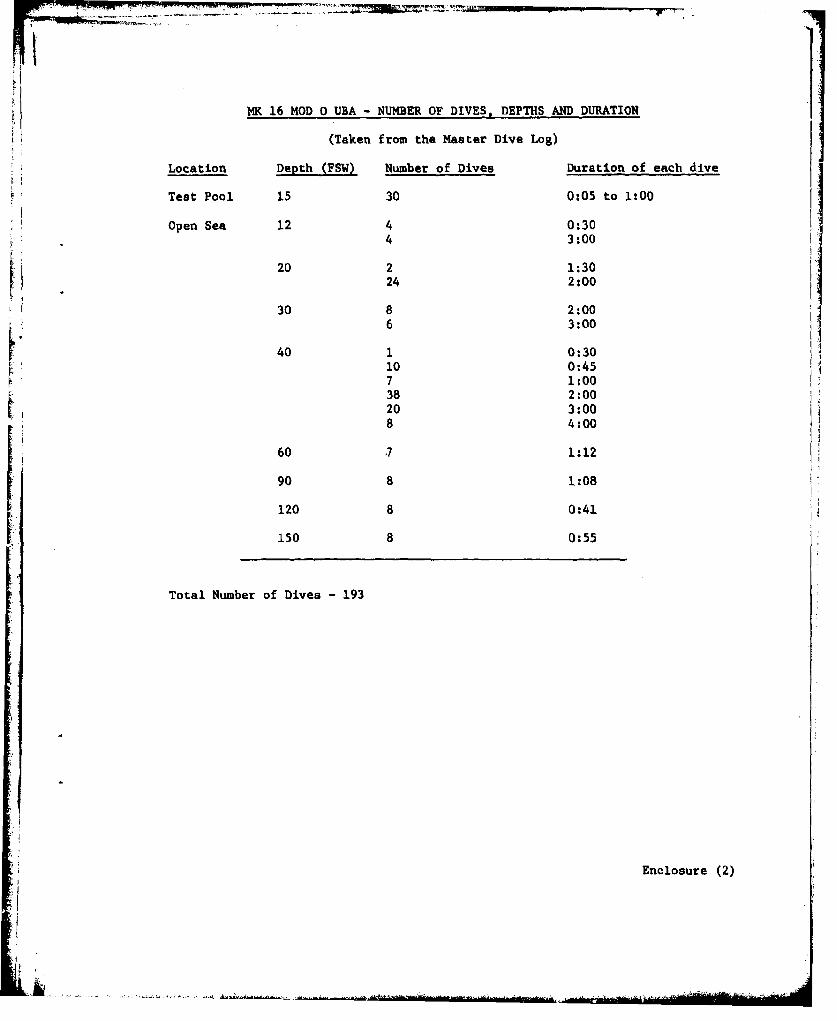
MK 16 MOD 0 UBA - NUMBER OF DIVES, DEPTHS AND DURATION
(Taken from the Master Dive Log)
Location Depth (FSW) Number of Dives Duration of each dive
Test Pool 15 30 0:05 to 1:00
Open Sea 12 4 0:304 3:00
20 2 1:3024 2:00
30 8 2:006 3:00
40 1 0:3010 0:457 1:0038 2:0020 3:008 4:00
60 .7 1:12
90 8 1:08
120 8 0:41
150 8 0:55
Total Number of Dives - 193
Enclosure (2)
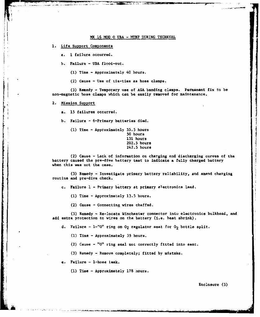
MKO 16 MOD 0 UBA -MTBF DURING TECHEVAL
1. Life Support Components
a. 1 failure occurred.
b. Failure - UBA flood-out.
(1) Time -Approximately 40 hours.
(2) Cause -Use of tie-ties as hose clamps.
(3) Remedy -Temporary use of AGA banding clamps. Permanent fix to beIi non-magnetic hose clamps which can be easily removed for maintenance.
2. Mission Support
a. 15 failures occurred.J
b. Failure -6-Primary batteries died.
[I (1) Time -Approximately 35.5 hours50 hours131. hours202.5 hours
242.5 hours
(2) Cause - Lack of information on charging and discharging curves of thebattery caused the pre-dive battery test to indicate a fully charged batterywhen this was not the case.
(3) Remedy - Investigate primary battery reliability, and amend chargingroutine and pre-dive check.
c. Failure 1I Primary battery at primary electronics lead.
(1) Time -Approximately 13.5 hours.
(2) Cause -Connecting wires chaf fed.
(3) Remedy -Re-locate Winchester connector intu electronics bulkhead, andadd extra protection to wires on the battery (i.e. heat shrink).
d. Failure - l-"0" ring on 02 regulator seat for 02 bottle split.
(1) Time -Approximately 35 hours.
(2) Cause -"0" ring seal not correctly fitted into seat.
(3) Remedy -Remove completely; fitted by mistake.
e. Failure - 1-hose leak.
(1) Time -Approximately 178 hours.
Enclosure (3)
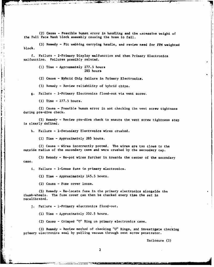
(2) Cause - Possible human error in handling and the excessive weight ofthe Full Face Mask block assembly causing the hose to fail.
(3) Remedy - Fit webbing carrying handle, and review need for FFM weightedblock.
f. Failure - 2-Primary Display malfunction and then Primary Electronicsmalfunction. Failures possibly related.
(1) Time - Approxmately 277.5 hours285 hours
(2) Cause - Hybrid Chip failure in Primary Electronics.
(3) Remedy - Review reliability of hybrid chips.
g. Failure - 1-Primary Electronics flood-out via vent screw.
(1) Time - 277.5 hours.
(2) Cause - Possible human error in not checking the vent screw tightnessduring pre-dive check.
(3) Remedy - Review pre-dive check to ensure the vent screw tightness stepis clearly defined.
h. Failure - 1-Secondary Electronics wires crushed.
(1) Time - Approximately 285 hours.
(2) Cause - Wires incorrectly potted. The wires are too close to theoutside radius of the secondary case and were crushed by the secondary cap.
(3) Remedy - Re-pot wires further in towards the center of the secondarycase.
i. Failure - 1-Loose fuze in primary electronics.
(1) Time - Approximately 145.5 hours.
(2) Cause - Fuze cover loose.
(3) Remedy - Re-locate fuze in the primary electronics alongside thethumb-wheels. The fuze cover can then be checked every time the set isrecalibrated.
J. Failure - 1-Primary electronics flood-out.
(1) Time - Approximately 202.5 hours.
(2) Cause - Crimped "0" Ring on primary electronics case.
- (3) Remedy - Review method of checking "0" Rings, and investigate checkingprimary electronics seal by pulling vacuum through vent screw penetrator.
Enclosure (3)
2

1K 16 MOD 0 UBA SPARE PARTS OUTFIT - PROPOSED LIST
Spare Parts For Three MK 16 MOD 0 UBA's
1 Primary cable 1 Secondary cable
1 Electronics cable to canister 1 Diluent HP hose
1 Canister securing nut (starbolt) 1 Upper moisture pad securing ring
1 Secondary display assembly 1 Primary electronics assembly (including
1 Primary display assembly Lee valve)
6 Hoses -, mouthpiece 2 Pressure gage - adapter couplings
6 Fuses 3/10 amp 6 Dunce caps
6 Large yellow thread protectors (outside) 9 Primary batteries
6 Sets of harness pins 21 Secondary batteries
1 Vent valve complete 1 Diaphragm
3 02 by-pass Dill valves 3 02 pneumatics check valves
1 Primary electronics vent valve screw 3 Diluent by-paso Dill valves
3 02 in-line filters 1 Backpack cover latch complete
12 Upper moisture pads 3 Diluent in-line filters
3 Pad compression 12 Lower moisture pads
2 Check valve housings (AGA) 1 Spare mouthpiece complete (AGA)
2 Sets AGA O-rings complete (AGA) 6 Check valves (AGA)
6 Sets hose clamps complete 2 Screws for mouthpiece collar (AGA)
1 Set of all screws/washers/nuts/etc. 1 Set of all O-rings used or cleaned in
1 ,Diaphragm clamp pre-dive/post-dive and PMS
3 Diluent add Dill valves 1 Set hydrophobic filters
1 Diluent regulator complete 1 02 regulator complete
1 Diluent regulator spring 1 02 regulator spring
1 Set diluent regulator shims 1 Set 02 regulator shims
1 Set by-pass springs and washers 1 By-pass valve button
7 Primary battery chargers 1 02 HP hose
3 Grommett, sensorEnclosure (4)
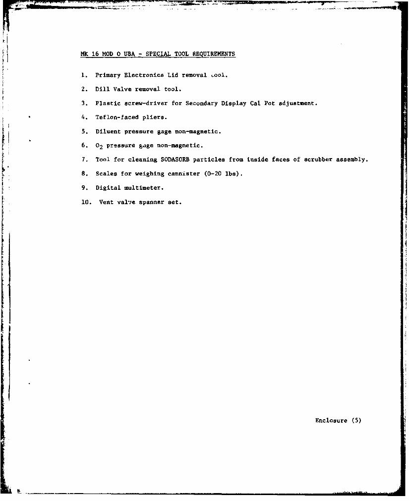
MK 16 MOD 0 UBA - SPECIAL TOOL REQUIREMENTS
1. Primary Electronics Lid removal .ool.
2. Dill Valve removal tool.
3. Plastic screw-driver for Secondary Display Cal Pot adjustment.
4. Teflon-faced pliers.
5. Diluent pressure gage non-magnetic.
6. 02 pressure gage non-magnetic.
7. Tool for cleaning SODASORB particles from inside faces of scrubber assembly.
8. Scales for weighing cannister (0-20 ibs).
9. Digital multimeter.
10. Vent valve spanner set.
Enclosure (5)
M4K 16 MOD 0 UBA -TRAINING COURSE PLAN AND LEARNING OBJECTIVES -NEDU COMMENTS
1. The present Navy Training Plan (NTP) states that a basic M4K 16 MOD 0 UBACourse will be 8 days and a refresher 5 days. These course lengths appear tobe very short as the 14K 16 MOD 0 UBA, while not a complex equipment, requiresa greater understanding of its operation and maintenance than previous EODdiving equipments. It is recommended that the course be designed without timeconstraints and the course length, vis-a-vis course content, be reviewed tomeet training constraints such as number of days available.
2. The Instructional Systems Development - Phase 11 Preliminary appears to bebased on the Pre-dive and Supervisor Check Lists. This is not considered to be
a practical method; and, when used during TECHEVAL, confused the Dive Subjects.A more practical approach would be to use the basic format in the O&M Manualplus other minor adjustments, i.e.:
a. Medical Aspects appertaining to the M4K 16 MOD 0 UBA.
b. Equipmene function and fit by sub-assemblies (including tools and test
equipment).I c. Total equipment operation.
d. Mixed Gas Transfer System.I
e. Pre-dive checks.
f. Emergency procedures.
g. Post-dive checks.
h. Trouble shooting.
i. Maintenance.
J. Supervisor checks.
k. Use of decompression tables.
3. To assist in the practical instruction of emergency procedures, a method ofmanipulating the primary display and switching the primary battery on and offshould be developed. An instructor display should be available showing whetherthe "LEE" valve is open or shut at the time the battery power is turned off, anda repeat secondary display should be situated topside to enable the instructor tomonitor UBA status. A bone-conductor type diver/topside communicator will berequired to use this proposed training aid effectively.
Enclosure (6)
......

MK 16 MOD 0 UBA - ENGINEERING CHANGE PROPOSALS (ECP's)
1. As a result of not only TECHEVAL but all DT II1, the following ECP's areproposed. Each sub-assembly is taken in turn as laid out in the Parts Lists inthe DRAFT O&M Manual using part descriptions from these lists.
2. Scrubber Assembly
a. The Assembly Diaphragm, on several occasions, was incorrectly fitted to theCenter Section Assembly and prevented the correct operation of the Diluent addvalve. The Band Assembly holding the Assembly Diaphragm also was incorrectlyfitted. The O&M Manual should stress the need to ensure the Assembly Diaphragmis correctly fitted to the Center Section Assembly and the Band Assembly locatedsuch that the tensioning screw is easily accessable when the Scrubber Assembly isfitted into the back-pack and that the screw does not foul the correct fitting ofthe Diluent Bottle. The addition of a lip to the Assembly Diaphragm will ensurethe diaphragm is evenly fitted to the Center Section Assembly prior to the BandAssembly being tightened.
b. The Absorbent Pads (also called Discs) are manufactured of a material thatreacts with the caustic solution that can exit the Canister Assembly. This materialShould be changed to a non-reactive material. The Top Pads (three) should be replacedwith one thick pad the same thickness as the Bottom Pad.
c. The Bottom Pad Support was removed before TECHEVAL as not required. It hadnot been part of the MK 16 MOD 0 USA outfit in previous tests.
d. The Assembly Cover is secured to the Center Section by a Star Bolt. Duringinitial tests, it was noted that the cover can flex. It is recomnended that thecover is secured with four pins and locking slides around the lower edge of the
cover. This will not only hold the cover firmly on, but prevent the "0" ring sealfrom being broken and relieve tension off the Center Section Assembly. One cover wascracked during TECHEVAL when a UBA was dropped onto the bottom of the dive boatstriking a sharp edge. The divers also reported that fish were attracted to thereflection off the cover. The recommended change for these two problems is toleave the Assembly Cover as it is now, but use the Backpack Cover configuration asprovided for the MK 15 UBA.
e. The Band Assembly nylon screw showed excessive wear for the number of timesthis screw was used. This may have been due to incorrect screw-drivers being used,and should be further examined during OPEVAL. The rivets holding the band and thenylon adjustment fixture together showed rust. This should also be examined furtherduring OPEVAL.
3. Center Section Assembly
a. The exhalation and inahaltion ports should be increased to 1-1/4" diaueter.The hose connections should also be larger, and the hose fittings made such that theinternal diameters of the hoses and the ports remains equal.
b. Consideration should be made to changing the support lid as noted in 2.d.above. This can then enable the Bracket, Sensor, to be part of the moulded center
Enclosure (7)
• • . . . -' '-- ',•.. ..... - • '•, •, .... • ........• • ... • ' i* • •'• • • • • •:1... . •!'•'"•i ........
section structure with the Sensor, Hyperbaric Oxygen then becoming a plug-in unitthereby eliminating many small metal parts, including the Star Bolt.
c. The connection wires for the sensors are exposed, and require care to
avoid catching them with the Canister Assembly during pre-dive assembly. These
wires would also be eliminated with the inclusion of paragraph b. above as an ECP.
d. The sensor bracket should be clearly numbered (I to 3) to ensure theF sensor and the thumb-wheel calibration switches in the electronics assembly are
easily identified, i.e. 1=1, 2-2, 3-3.
4. Canister Assembly
a. The Pad Compression was "eaten" away by the caustic reaction of the
SODASORB and should be replaced with a new non-reactive material.
b. The ribs on the bottom outside of the Housing Canister can foul on the"ostand-off" screws by the Exhalation Port. The Housing Canister should be etchedwith line up marks or a gap left in all the lower ribs.
5. Electronics Assembly
V a. The Cover, Battery Electronics is difficult to remove, and the presentspecial tool is causing wear on the Cover and Assembly, Electronics Housing. A
modification should be made to the Cover to allow easier removal.
b. The Ring, Locking became very tight on at least two of the PPM's, andrequired excessive effort to remove It. in some cases use of a chain wrench was
required. The reason should be investigated and overcome.
c. The battery connectors should be re-sighted with the female connector beingFmoulded into the battery lower bulkhead. This connector must be watertight. The
present cable penetrators are not.
d. The Electronics Fuze should be re-sighted from the bottom of the electronicssection to a position next to the thumb-wheel pots. This will enable easy replace-ment of the Fuze by the operator.
e. The Assembly, Oxygen Valve should be made part of the whole electronicsassembly, and the present requirement to replace the valve if it fails shouldbecome a replacement of the whole electronics assembly. This will enable a better
* and permanent water tight seal to be fitted between the Valve and ElectronicsAssembly.
f. There is no way to check the Electronics Assembly for water-tightness. Itis considered that a leak test using a low vacuum by fitting a vacuum puup and
* gauge into the vent screw hole during pre-dive procedures, could provide the answer.Further investigation is recommended.
g, Many of the divers indicate that -in External "ON-OFF" switch should befitted to enable long transits to the dive sight with the set checked-out ready fordiving but with no discharge on the battery. The problem of the battery dischargingmay be overcome once the reliability of both the electronics and batteries havebeen established. However, the incorporation of an "ON-OFF" switch should stillbe considered.
Enclosure (7)k 2

6. Primary Display Assembly
a. The clarity of the LED's was a major concern during TECHEVAL. In brightsunlight and clear water, the LED could not be clearly seen. The green LED alsoturned yellow at approximately 15 FSW. It is recommended that back-shielding beprovided to ensure the LED's are not blocked out by background lighting. Therewere no night dives so the clarity at night was not tested. A night evolutionshould be carried out during OPEVAL and the clarity of the LED's re-evaluated.
* b. There were several comments from the divers on the size and location ofthe Primary Display. This should be checked again during OPEVAL.
* c. The light code caused comment. It was considered to be confusing as theindication still requires the secondary to be checked and a decision to be madeas to what a change of lights really means. The requirements at the Primary
Display indications vis-a-vis the EOD mission and operational requirement shouldbe reviewed and re-established with any changes incorporated into the productionequipments such as using one (RED) warning light which indicates any of the rigfailures/malfunctions and the diver then using the Secondary and aborting the dive.
7. Secondary Display
a. The Secondary Display is large and bulky; and, when attached to the harness,is difficult to locate and re-connect when the MK 16 MOD 0 UBA is worn with the
MK 4 Life Preserver. The Snap (Spring) hook is not reliable. It can jam open or
"Jump" its hook. It is not possible to check if the unit is water-tight prior tothe dive. The readout is difficult to locate on the cylindrical housing, and theread out is poor in low visibility. The Secondary Battery can stick in the batterypocket due to suction, and the battery connectors should be reversed (the femalein the bulkhead not the male) to prevent irrepairable damage to the male connector.The internal bulkhead should be water-tight. For all of the above problems it isrecommended that a new design secondary be produced of a much smaller size with arechargeable battery common to the Primary Battery (i.e. 6V gel battery) and locatedin the Backpack. A further recommendation of combining this display with a shared-time HP bottle gage display would also enhance the overall diver safety andoperation. (The gage will be referred to in a later sub-paragraph.)
8. Regulator Assemblies, Oxygen - Diluent
a. The Bottle Valve Asi3embly is difficult to pass through the Yoke, Regulatorbecause the Regulator Assembly is fixed to the Backpack. Towards the end ofTECR~EVAL brass slivers were being pressed Into the bottle "W~ring and causing highusage of the "O"rings. The hardness of the metal and design of the Yoke shouldbe reviewed. (This will be referred to in a later sub-paragraph.)
b. The Knob, Regulator is difficult to tighten and release, and should bereplaced with a "T" handle.
9. Bottle and Valve Assemblies, Oxygen - DiluentJ1
a. The handle on the Valve Assembly is difficult to turn while in the water.The backpack access to the handle is very poor when wearing gloves, and needs to
Enclosure (7)
3
be enlarged. The need to be able to turn off the bottles in the water is essentialas this evolution is a listed Emergency Procedure. The design should be reviewedin conjunction with sub-paragraph 8a above.
b. The Bottle Assembly interface with the Regulator Assembly started to showwear towards the end of TECHEVAL, and slivers of brass were being pressed into thebottle "O"ring. The hardness of the metal should be reviewed. (See sub-paragraph8a above.)
c. The present bottle color coding should be increased to ensure the bottlescannot be interchanged accidentally, i.e. Oxygen all green, diluent all black or, atleast, color-coded around the bottle necks.
10. Cover Housing Assembly
a. The whole of the MK 16 MOD 0 UBA components are a tight fit in the Backpackand the Cover Housing. On two of the PPM's, it was difficult to fit the Cover Housing.It is recommended that the Backpack size be slightly increased, and a new design Cover
Housing, as presently used with the HK 15 UBA, be introduced, (See sub-paragraph2.d. bove.b. The Primary Cable Securing Clamp on the Backpack broke on several occasions,
sad the Cover Housing fouled the cable. The design should be reviewed and modifiedas necessary to overcome this problem.
311. High Pressure Gage Assembly[ a. The present Gages are too small, fog up and are located in the wrong place.They should be changed and care taken to ensure they can be easily read under alloperational diving conditions.
b. The location and securing method of the Gages to the Harness needs to bei~roved. Account should be taken of the fit of the MK 4 Life Preserver and thelocation of the Gages.
c. It is recommended that as a long-term goal, the Oxygen and Diluent Cagesbe re-designed as one unit possibly combined with a new Secondary Display. Usingpressure transducers, it should be possible to reduce the gages to a time-sharingLCD using the same power source as the Secondary Display. This will reduce thenumber of cables and fittings from the Backpack to the front of the Harness from3 to 1. It should be noted that when the Secondary Display has to be checkedduring miost Emergency Procedures, it is also necessary to check the H.P. Gages.A combined design will therefore be easier for the operator.
12. Harness Assembly
a. The Harness Assembly requires a lifting point to be fitted between theShoulder Straps and behind the diver's neck to assist with the handling of theURlA when out of the water.
b. The pins securing the harness to the backpack come loose and fall out.-The pins should be changed.
Enclosure (7)
4
c. The Quick-Release Buckle on the Waist Strap is similar to that of theMK 4 Life Preserver. Should there ever arise a need to ditch the set whil( inthe water it could confuse the diver as to which buckle he should release. Thisproblem should be further reviewed during OPEVAL.
d. During TECHEVAL and other pool tests at NEDU, the divers have voiced anopinion that an optional jockstrap should be fitted. The desirability of ajockstrap should be examined during OPEVAL.
e. Some of the divers had difficulty with their weight belt and the basicconfiguration of the set. This was with those divers who required a large numberof weights. No solution is offered but the use of large hip weights was not
totally successful due to the side hinges on the backpack getting in the way.This problem whould be further evaluated during OPEVAL.
13. Pneumatics Assembly
a. The Pneumatics Assembly has one unsolved problem. When carrying out benchtests it was noted that when the Diluent Bottle was removed and the Oxygen Bottlestill connected up, when the Oxygen By-pass was operated to remove HP oxygen fromthe Oxygen Regulator prior to Oxygen Bottle removal, oxygen leaked up through theDiluent Regulator. The reverse happened when the Oxygen Bottle was disconnectedwith the Diluent Bottle connected up and the Diluent By-pass activated. The onlylogical conclusion is that the By-pass Dill Valve Housings allow gas to leak backup past the outside of the Dill Valve. The concern is that the oxygen clean systemcan be contaminated with air and that oxygen can pass through an unclean system inthe diluent side of the assembly. This problem needs to be resolved and gascontamination prevented.
b. The by-pass push buttoms should be changed to indicate 02 or diluent. It isrecommended that the same code is used as the MK 15 UBA, 02 has an "0" and diluenthas a "Cone".
14. Shipping Container
a. The Shipping Container cannot hold the Full Face Mask (FFM). If the FFM isremoved from the system, the container is large enough, but its weight, plus theMK 16 MOD 0 UBA, is over 70 lbs. Therefore, is can not be shipped as personalbaggage by air freight. It may be desirable to have a second container for the HPBottles (which could include the FFM if still required) thereby keeping the weightsof each container below 70 lbs. The HP bottle container is also desirable to enablethe bottles to be safely removed from the UBA and stowed where they cannot rollaround.
15. Full Face Mask (FFM)
a. Considerable effort has been expended to overcome the problems arising fromthe hydro-static lung loading pressure variations of the MK 16 MOD 0 UBA and thenon-magnetic FIM interface. The nose-clearing device in the FFM was also found tobe unsuitable due to the need to over-tighten the FFM to overcome the face maskleaks. After considerable effort to resolve the IM squeeze effect, gas leaks,water leaks, nose-clearing device and general comfort, it is recommended that theFM be replaced with a mouthpiece and swim-mask. The swim-mask should be a low
Enclosure (7)
5 -

-Wolume "pinocchio"-type which will reduce the face-squeeze problem. The mouthpieceshould have a retaining strap to prevent the hydro-static lung loading pressure"variation causing the mouthpiece to "blow-out" of the diver's mouth.
b. The present hose clamps require replacement with a non-magnetic easily
Simove~able type that will ensure a water-tight seal under all operational divingconditions.
16. Buoyancy
a. Several divers complained of poor buoyancy control in shallow water (0-30[SW). This is a real problem when attempting to maintain accurate depths for,decompression. It is recommended that either a descending line be used for alldecompression dives or a bouyancy compensator is introduced as part of the MK 16WD 0 UBA outfit.
17. Compatibility with other essential diver's equipments
a. The MK 16 MOD 0 UBA should be tested with all the diver-worn equipmentsproposed in the EOD operational scenario. This should include all diving suits(ry and wet types) and life preservers. TECHEVAL did not fully exploit thismkpect of the total EOD system.
ii.
Enclosure (7)
6
1 4 ---.--.

El .
MK 16 MOD 0 UBA - PRE-PRODUCTION MODEL (PPM) CONFIGURATION DIFFERENCES
1I All PPM's
a. Sensor ID should be permanently marked.
b. Dunce caps to be available for 02 and diluent regulators when bottlesnot fitted.
c. Dust caps to be available for inhalation/exhalation ports when hosesdisconnected.
2. PPM o
a. Thumb wheel calibration pots in a different order to the other 5 PPM's -
Sre-arrange order.
b. Bottle cushion pads missing - fit new pads.
c. HP gage adaptors of old design - change to new design.
d. Secondary male winchester connector broken - refit with new connector.
3. PPM 2
a. Bottle cushion pads missing - fit new pads.
b. HP gage adaptors of old design - change to new design.
c. Diluent regulator assembly, knob, regulator - change to tee-bar type.
d. Diluent and 02 regulator support bracket screws incorrect type - changeto correct type.
e. Primary electronics mount bracket screws are a different type to otherPPM's - change screws and/or fitting.
4. PPM3
a. Bottle cushion pads missing - fit new pads.
b. Diluent and 02 regulator assemblies, knob, regulator - change to tee-bartype.
c. Rubber pads on regulator support brackets - to be fitted.
d. Screw missing from latch assembly - replace.
5. PPM4
a. Latch broken - replace.
b. Primary electronics defective - repair.
Enclosure (8)
'n

=7 '
c. Diluent and 02 regulator assemblies, knob, regulator -change to tee-bar type.
6. PPM 5
a. Diluent and 02 regulator assemblies, knob, regulator - change to tee-bartype.
7. PPM6
a. Diluent and 02 regulator assemblies, knob, regulator - change to tee-barrU type.
b. Secondary assembly wiring crushed -replace and re-pot towards center ofassembly and clear of cap.
2Enclosure (B)A
-. -- - mm
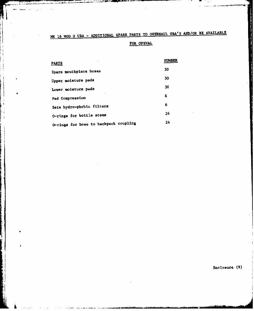
MK 16 MOD 0 UBA - ADDITIONL" SPARE PARTS TO OVERHAUL UBA'S AND/OR BE AVAILABLE
FOR OPEVAL
PARTS ME
Spare mouthpiece hoses 30
Upper moisture pads 30
Lower moisture pads 30
Pad Compression 6
Sets hydro-phobic filters 6
O-rings for bottle stems 24
O-rings for hose to backpack coupling 24
Enclosure (9)
JI
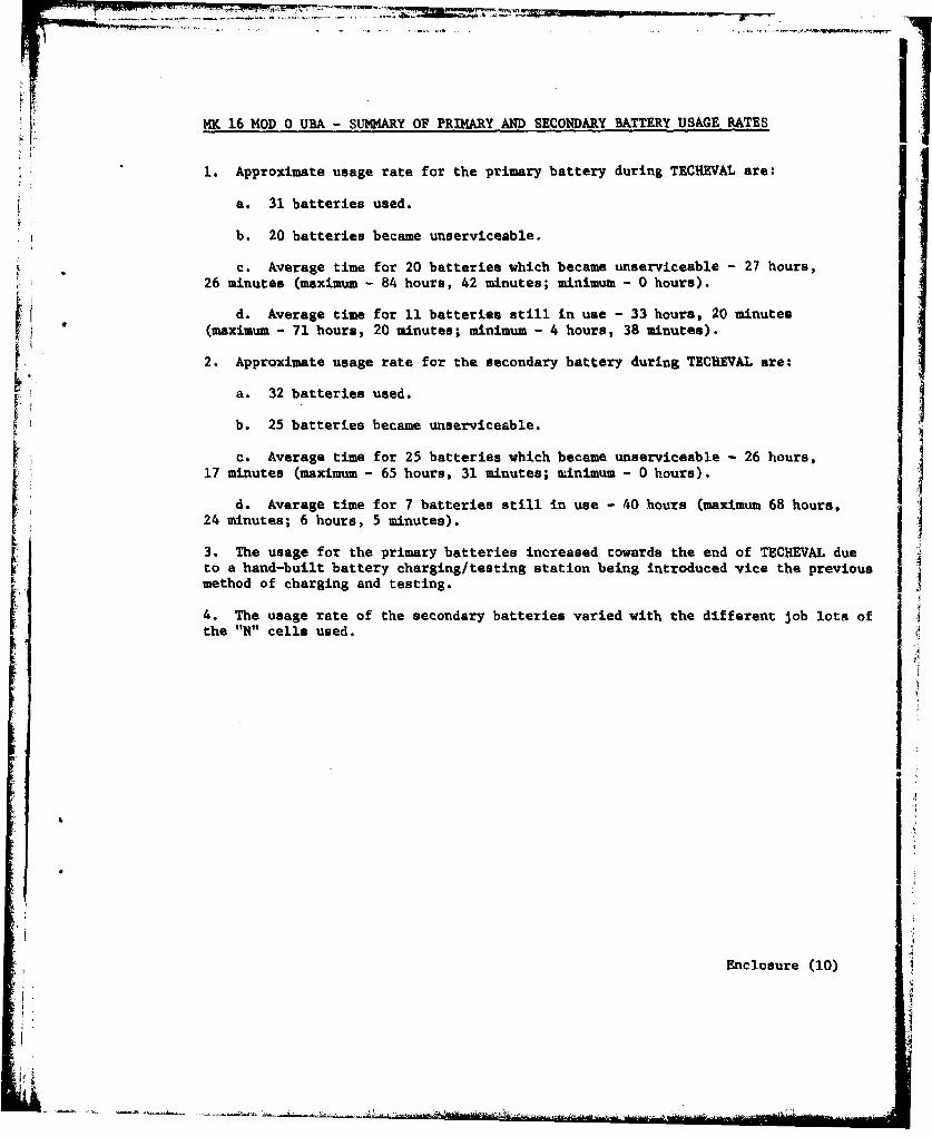
MK .16 MOD 0 U- SUMMARY OF PRIMARY AND SECONDARY BATTERY USAGE RATES
1. Approximate usage rate for the primary battery during TECHEVAL are:
a. 31 batteries used.
b. 20 batteries became unserviceable.
c. Average time for 20 batteries which became unserviceable - 27 hours,26 minutes (maximum - 84 hours, 42 minutes; minimum - 0 hours).
d. Average time for 11 batteries still in use - 33 hours, 20 minutes(maximum - 71 hours, 20 minutes; minimum - 4 hours, 38 minutes).
2. Approximate usage rate for the secondary battery during TECHEVAL are:
a. 32 batteries used.
b. 25 batteries became unserviceable.
c. Average time for 25 batteries which became unserviceable - 26 hours,17 minutes (maximum - 65 hours, 31 minutes; minimum - 0 hours).
d. Average time for 7 batteries still in use - 40 hours (maximum 68 hours,
24 minutes; 6 hours, 5 minutes).
3. The usage for the primary batteries increased towards the end of TECHEVAL dueto a hand-built battery charging/testing station being introduced vice the previousmethod of charging and testing.
4. Te usage rate of the secondary batteries varied with the different job lots of
the "N" cells used.
Enclosure (10)
I t

MK 16 MOD 0 UBA PRIMARY BATTERY CHARGING STATION AND METER FOR SECONDARY BATTERY
CHECK WIRING DIAGRAM AND OPERATING PROCEDURE
VOTE: Color code refers to colored sectors on meter faces.
Primary Voltmeter Primary Ampmeter Secondary Battery Tester
Red - 0 - 4.66 VDC Red - 6.80 - 119.0 mA Red - 0 - 7.40 VDCOrange - 4.66- 5.40 VDC Yellow - 52.2 - 68.0 mA Orange * 7.40 -8.94 VDCYellow - 5.40 - 5.95 VDC Green - 17.5 - 52.2 mA Green - 8.94 - 10 VDCGreen - 5.95 - 8.00 VDC
1. Good charger (no load)
a. Voltmeter - Orange (switch UP)
b. Ammeter - Green (saitch UP)
2. Bad charger (no load)
a. Voltmeter - Red (switch UP)
b. Am•eter - Green (switch UP)
3. Bad charger (with load)
a. Voltmeter - Green or Yellow (switch UP)
b. Ammeter - No Plunctuation
4. Bad battery
a. OPEN
(1) Voltmeter - Green or Yellow
(2) Ammeter - No Flunctuation
b. SHORT
(1) Voltmeter - Green (high)
(2) Ammeter - Red (high)
c. REVERSED LEADS
(I) Voltmeter - Red (pegged)
(2) Ammeter - Red (high)Enclosure (11)
i-
L !
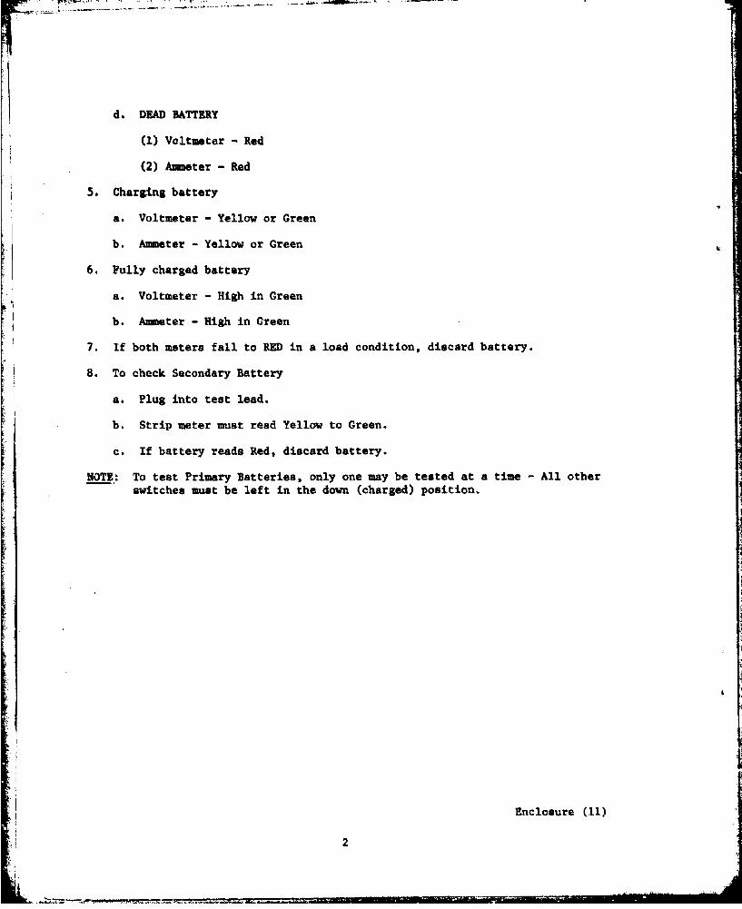
d.* DEAD BATTERY
(1) Voltmeter -Red
(2) Ammeter - Red
5. Charging battery
a. Voltmeter - Yellow or Green
b. Ammeter - Yellow or Green
6. Fully charged battery
a. Voltmeter - High in Green
b. Ammeter - High in Green
7. If both meters fall to RED in a load condition, discard battery.
8. To check Secondary Battery
a. Plug into test lead.
b. Strip meter must read Yellow to Green.
c. If battery reads Red, discard battery.-Alote
NOTE.: To test Primary Batteries, only one may be tested at a time-Alote
switches must be left in the down (charged) position.
Enclosure (11)
2

= LUFU 'U
LU
O a"
MWg
04.40
aa2N
UU
I-d
2412
LU6
UA
'go
Enclosure (1