lecture presentation - physics...
TRANSCRIPT

Chapter 16
Lecture Presentation
Superposition and Standing
Waves
© 2015 Pearson Education, Inc.

Slide 16-2
Chapter 16 PreviewLooking Ahead: Superposition
• Where the two water waves meet, the motion of the water
is a sum, a superposition, of the waves.
• You’ll learn how this interference can be constructive or
destructive, leading to larger or smaller amplitudes.
© 2015 Pearson Education, Inc.
Slide 16-3
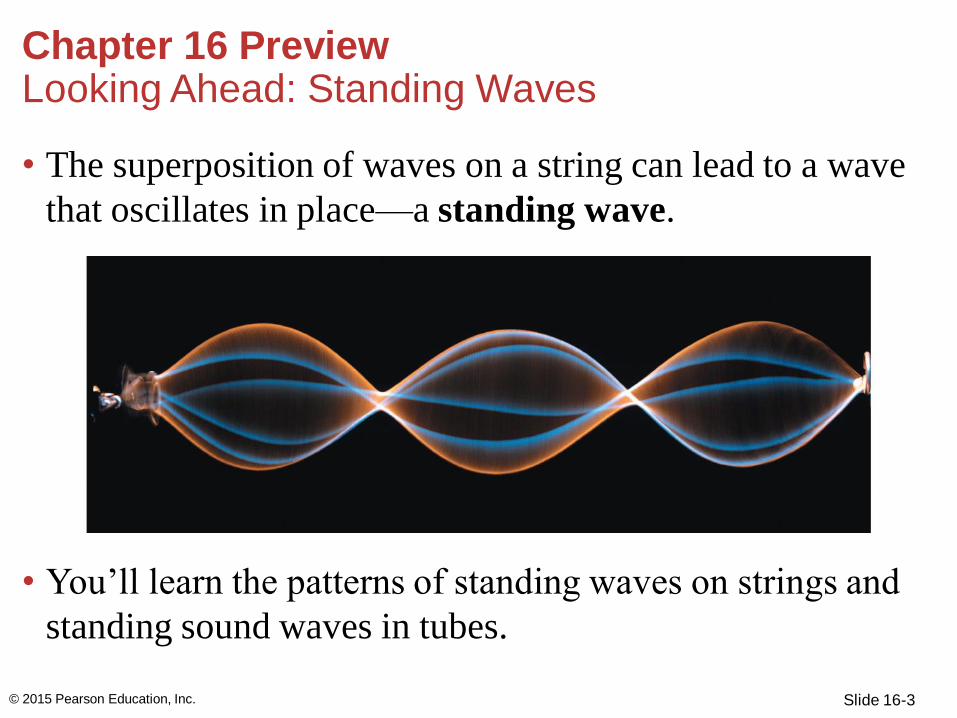
• The superposition of waves on a string can lead to a wave
that oscillates in place—a standing wave.
• You’ll learn the patterns of standing waves on strings and
standing sound waves in tubes.
Chapter 16 PreviewLooking Ahead: Standing Waves
© 2015 Pearson Education, Inc.

Slide 16-4
Chapter 16 PreviewLooking Ahead
© 2015 Pearson Education, Inc.
Text: p. 500

Section 16.1 The Principle of Superposition
© 2015 Pearson Education, Inc.
Slide 16-6
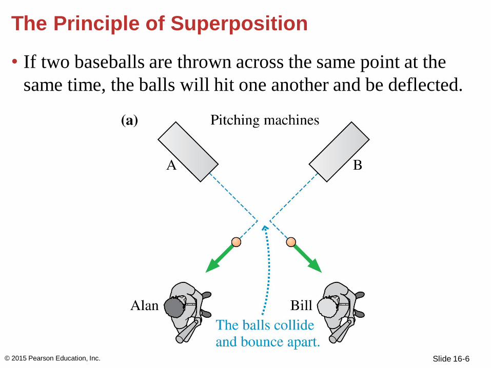
The Principle of Superposition
• If two baseballs are thrown across the same point at the
same time, the balls will hit one another and be deflected.
© 2015 Pearson Education, Inc.

Slide 16-7
The Principle of Superposition
• Waves, however, can pass
through one another. Both
observers would hear
undistorted sound, despite
the sound waves crossing.
© 2015 Pearson Education, Inc.

Slide 16-8
The Principle of Superposition
© 2015 Pearson Education, Inc.

Slide 16-9
The Principle of Superposition
• To use the principle of superposition, you must know the
displacement that each wave would cause if it were alone
in the medium.
• Then you must go through the medium point by point and
add the displacements due to each wave at that point.
© 2015 Pearson Education, Inc.

Slide 16-10
Constructive and Destructive Interference
• The superposition of two waves is called interference.
• Constructive interference occurs when both waves are
positive and the total displacement of the medium is larger
than it would be for either wave separately.
© 2015 Pearson Education, Inc.

Slide 16-11
Constructive and Destructive Interference
• The superposition of two waves is called interference.
• Constructive interference occurs when both waves are
positive and the total displacement of the medium is larger
than it would be for either wave separately.
© 2015 Pearson Education, Inc.

Slide 16-12
Constructive and Destructive Interference
• Destructive interference is when the displacement of the
medium where the waves overlap is less than it would be
due to either of the waves separately.
• During destructive interference, the energy of the wave is
in the form of kinetic energy of the medium.
© 2015 Pearson Education, Inc.

Slide 16-13
Constructive and Destructive Interference
• Destructive interference is when the displacement of the
medium where the waves overlap is less than it would be
due to either of the waves separately.
• During destructive interference, the energy of the wave is
in the form of kinetic energy of the medium.
© 2015 Pearson Education, Inc.

Slide 16-14
Constructive and Destructive Interference
• Destructive interference is when the displacement of the
medium where the waves overlap is less than it would be
due to either of the waves separately.
• During destructive interference, the energy of the wave is
in the form of kinetic energy of the medium.
© 2015 Pearson Education, Inc.

Section 16.2 Standing Waves
© 2015 Pearson Education, Inc.

Slide 16-16
Standing Waves
• Waves that are “trapped” and cannot travel in either
direction are called standing waves.
• Individual points on a string oscillate up and down, but
the wave itself does not travel.
• It is called a standing wave because the crests and troughs
“stand in place” as it oscillates.
© 2015 Pearson Education, Inc.

Slide 16-17
Superposition Creates a Standing Wave
• As two sinusoidal waves of equal wavelength and
amplitude travel in opposite directions along a string,
superposition will occur when the waves interact.
© 2015 Pearson Education, Inc.

Slide 16-18
Superposition Creates a Standing Wave
© 2015 Pearson Education, Inc.

Slide 16-19
Superposition Creates a Standing Wave
© 2015 Pearson Education, Inc.

Slide 16-20
Superposition Creates a Standing Wave
• The two waves are represented by red and by orange in the
previous figures. At each point, the net displacement of the
medium is found by adding the red displacement and the
orange displacement. The blue wave is the resulting wave
due to superposition.
© 2015 Pearson Education, Inc.

Slide 16-21
Nodes and Antinodes
• In a standing wave pattern,
there are some points that
never move. These points
are called nodes and are
spaced λ/2 apart.
• Antinodes are halfway
between the nodes, where
the particles in the medium
oscillate with maximum displacement.
© 2015 Pearson Education, Inc.

Slide 16-22
Nodes and Antinodes
• The wavelength of a
standing wave is twice the
distance between successive
nodes or antinodes.
• At the nodes, the
displacement of the two
waves cancel one another by
destructive interference. The
particles in the medium at a
node have no motion.
© 2015 Pearson Education, Inc.

Slide 16-23
Nodes and Antinodes
• At the antinodes, the two
waves have equal magnitude
and the same sign, so
constructive interference at
these points give a
displacement twice that of
the individual waves.
• The intensity is maximum
at points of constructive
interference and zero at
points of destructive
interference.
© 2015 Pearson Education, Inc.

Section 16.3 Standing Waves on a String
© 2015 Pearson Education, Inc.

Slide 16-25
Reflections
• A wave pulse traveling along
a string attached to a wall
will be reflected when it
reaches the wall, or the
boundary.
• All of the wave’s energy is
reflected; hence the
amplitude of a wave
reflected from a boundary
is unchanged.
• The amplitude does not change, but
the pulse is inverted.
© 2015 Pearson Education, Inc.

Slide 16-26
Reflections
• Waves also reflect from a discontinuity, a point where
there is a change in the properties of the medium.
• At a discontinuity, some of the wave’s energy is
transmitted forward and some is reflected.
© 2015 Pearson Education, Inc.

Slide 16-27
Reflections
• When the string on the right is more massive, it acts like a
boundary so the reflected pulse is inverted.
© 2015 Pearson Education, Inc.

Slide 16-28
Try It Yourself: Through the Glass Darkly
A piece of window glass is a
discontinuity to a light wave, so
it both transmits and reflects
light. To verify this, look at the
windows in a brightly lit room
at night. The small percentage
of the interior light that reflects from windows is more
intense than the light coming in from outside, so reflection
dominates and the windows show a mirror-like reflection of
the room. Now turn out the lights. With no more reflected
interior light you will be able to see the transmitted light
from outside.
© 2015 Pearson Education, Inc.

Slide 16-29
Creating a Standing Wave
• Standing waves can be
created by a string with
two boundaries where
reflections occur. A
disturbance in the middle
of the string causes waves
to travel outward in both
directions.
• The reflections at the ends
of the string cause two
waves of equal amplitude and wavelength to travel in
opposite directions along the string.
© 2015 Pearson Education, Inc.
[Insert Figure 16.11]

Slide 16-30
Creating a Standing Wave
• Two conditions must be
met in order to create
standing waves on the
string:
• Because the string is
fixed at the ends, the
displacements at x = 0
and x = L must be zero
at all times. Stated
another way, we require
nodes at both ends of the string.
• We know that standing waves have a spacing of λ/2 between
nodes. This means that the nodes must be equally spaced.
© 2015 Pearson Education, Inc.
[Insert Figure 16.11
(repeated).]

Slide 16-31
Creating a Standing Wave
• There are three possible
standing-wave modes of a
string.
• The mode number m helps
quantify the number of
possible waves in a standing
wave. A mode number m 1
indicates only one wave, m 2
indicates 2 waves, etc.
© 2015 Pearson Education, Inc.

Slide 16-32
Creating a Standing Wave
• Different modes have different
wavelengths.
• For any mode m the wavelength is
given by the equation
• A standing wave can exist on the
string only if its wavelength is
one of the values given by this
equation.
© 2015 Pearson Education, Inc.

Slide 16-33
Creating a Standing Wave
• The oscillation frequency corresponding to wavelength λm
is
• The mode number m is equal to the number of
antinodes of the standing wave.
© 2015 Pearson Education, Inc.

Slide 16-34
Creating a Standing Wave
• The standing-wave modes are frequencies at which the
wave “wants” to oscillate. They can be called resonant
modes or resonances.
© 2015 Pearson Education, Inc.

Slide 16-35
The Fundamental and Higher Harmonics
• The first mode of the standing-wave modes has the
frequency
• This frequency is the fundamental frequency of the
string.
© 2015 Pearson Education, Inc.

Slide 16-36
The Fundamental and Higher Harmonics
• The frequency in terms of the fundamental frequency is
fm = mf1 m = 1, 2, 3, 4, . . .
• The allowed standing-wave frequencies are all integer
multiples of the fundamental frequency.
• The sequence of possible frequencies is called a set of
harmonics.
• Frequencies above the fundamental frequency are referred
to as higher harmonics.
© 2015 Pearson Education, Inc.

Slide 16-37
Example 16.2 Identifying harmonics on a string
A 2.50-m-long string vibrates
as a 100 Hz standing wave
with nodes at 1.00 m and
1.50 m from one end of the
string and at no points in
between these two.
Which harmonic is this?
What is the string’s
fundamental frequency? And
what is the speed of the
traveling waves on the string?
© 2015 Pearson Education, Inc.

Slide 16-38
Example 16.2 Identifying harmonics on a string (cont.)
PREPARE We begin with the
visual overview in
FIGURE 16.15, in which we
sketch this particular standing
wave and note the known and
unknown quantities. We set
up an x-axis with one end of
the string at x 0 m and the
other end at x 2.50 m. The ends of the string are nodes,
and there are nodes at 1.00 m and 1.50 m as well, with no
nodes in between.
© 2015 Pearson Education, Inc.

Slide 16-39
Example 16.2 Identifying harmonics on a string (cont.)
We know that standing-wave
nodes are equally spaced, so
there must be other nodes on
the string, as shown in Figure
16.15a. Figure 16.15b is a
sketch of the standing-wave
mode with this node
structure.
© 2015 Pearson Education, Inc.

Slide 16-40
Example 16.2 Identifying harmonics on a string (cont.)
SOLVE We count the number
of antinodes of the standing
wave to deduce the mode
number; this is mode m = 5.
This is the fifth harmonic.
The frequencies of the
harmonics are given by fm =
mf1, so the fundamental
frequency is
© 2015 Pearson Education, Inc.

Slide 16-41
Example 16.2 Identifying harmonics on a string (cont.)
The wavelength of the
fundamental mode is
λ1 = 2L = 2(2.50 m) = 5.00 m,
so we can find the wave speed
using the fundamental
relationship for sinusoidal
waves:
v = λ1f 1 = (20 Hz) (5.00 m) = 100 m/s
© 2015 Pearson Education, Inc.

Slide 16-42
Example Problem
A particular species of spider spins a web with silk threads
of density 1300 kg/m3 and diameter 3.0 μm. A passing insect
brushes a 12-cm-long strand of the web, which has a tension
of 1.0 mN, and excites the lowest frequency standing wave.
With what frequency will the strand vibrate?
© 2015 Pearson Education, Inc.

Slide 16-43
Stringed Musical Instruments
• The fundamental frequency can be written in terms of the
tension in the string and the linear density:
• When you pluck a bow or string of an instrument, initially
you excite a wide range of frequencies; however the
resonance sees to it that the only frequencies to persist are
those of the possible standing waves.
• On many instruments, the length and tension of the strings
are nearly the same; the strings have different frequencies
because they differ in linear density.
© 2015 Pearson Education, Inc.

Slide 16-44
Example 16.4 Setting the tension in a guitar string (cont.)
SOLVE The linear density of the string is
We can rearrange Equation 16.5 for the fundamental
frequency to solve for the tension in terms of the other
variables:
© 2015 Pearson Education, Inc.

Slide 16-45
Two strings with linear densities of 5.0 g/m are stretched
over pulleys, adjusted to have vibrating lengths of 50 cm,
and attached to hanging blocks. The block attached to String
1 has a mass of 20 kg and the block attached to String 2 has
mass M. When driven at the same frequency, the two strings
support the standing waves shown.
A. What is the driving frequency?
B. What is the mass of the block
suspended from String 2?
Example Problem
© 2015 Pearson Education, Inc.

Slide 16-46
Standing Electromagnetic Waves
• A laser establishes standing light waves between two
parallel mirrors that reflect light back and forth.
• The mirrors are the boundaries and therefore the light
wave must have a node at the surface of each mirror.
© 2015 Pearson Education, Inc.

Slide 16-47
Example 16.5 Finding the mode number for a laser (cont.)
SOLVE The standing light wave in a laser cavity has a mode
number m that is roughly
ASSESS The wavelength of light is very short, so we’d
expect the nodes to be closely spaced. A high mode number
seems reasonable.
© 2015 Pearson Education, Inc.

Section 16.4 Standing Sound Waves
© 2015 Pearson Education, Inc.
Slide 16-49
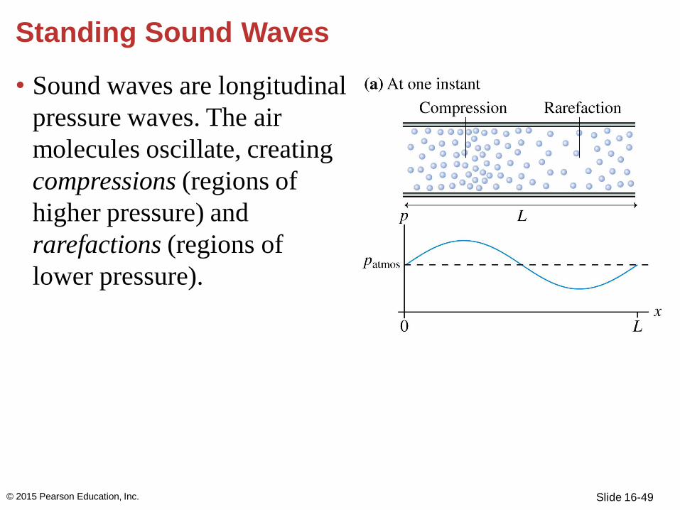
Standing Sound Waves
• Sound waves are longitudinal
pressure waves. The air
molecules oscillate, creating
compressions (regions of
higher pressure) and
rarefactions (regions of
lower pressure).
© 2015 Pearson Education, Inc.

Slide 16-50
Standing Sound Waves
• Sound waves traveling in a
tube eventually reach the
end where they encounter
the atmospheric pressure
of the surrounding
environment: a discontinuity.
• Part of the wave’s energy is
transmitted out into the
environment, allowing you
to hear the sound, and part is
reflected back into the tube.
© 2015 Pearson Education, Inc.

Slide 16-51
Standing Sound Waves
• Air molecules “slosh” back
and forth, alternately pushing
together (compression) and
pulling apart (rarefaction).
© 2015 Pearson Education, Inc.

Slide 16-52
Standing Sound Waves
• A column of air open
at both ends is an
open-open tube.
• The antinodes of a
standing sound wave
are where the pressure
has the largest
variation: maximum
compressions and
rarefactions.
© 2015 Pearson Education, Inc.
[Insert Figure 16.18 (c).]

Slide 16-53
Standing Sound Waves
• Air molecules in tubes that are closed at one or both ends
will rush toward the wall, creating a compression, and then
rush away leaving a rarefaction.
• Thus a closed end of an air column is an antinode of
pressure.
© 2015 Pearson Education, Inc.

Slide 16-54
Standing Sound Waves
© 2015 Pearson Education, Inc.

Slide 16-55
Standing Sound Waves
© 2015 Pearson Education, Inc.

Slide 16-56
Standing Sound Waves
© 2015 Pearson Education, Inc.

Slide 16-57
Standing Sound Waves
• The wavelengths and frequencies of an open-open tube
and a closed-closed tube are
• The fundamental frequency of an open-closed tube is
half that of an open-open or a closed-closed tube of the
same length.
[Insert Equation 16.7 p. 511]
© 2015 Pearson Education, Inc.

Slide 16-58
Standing Sound Waves
© 2015 Pearson Education, Inc.
Text: p. 511

Slide 16-59
Standing Sound Waves
© 2015 Pearson Education, Inc.
Text: p. 512

Slide 16-60
Standing Sound Waves
• The curve of equal
perceived loudness shows
the intensity level required
for different frequencies to
give the impression of equal
loudness.
• The two dips on the curve
are resonances in the ear
canal where pitches that should seem quieter produce the
same perceived loudness.
© 2015 Pearson Education, Inc.

Section 16.5 Speech and Hearing
© 2015 Pearson Education, Inc.

Slide 16-62
The Frequency Spectrum
• Most sounds are a mix, or
superposition, of different
frequencies.
• The frequency spectrum of
a sound is a bar chart showing
the relative intensities of
different frequencies.
• Your brain interprets the fundamental frequency as the
pitch and uses the higher harmonics to determine the tone
quality, or timbre.
© 2015 Pearson Education, Inc.
Slide 16-63
The Frequency Spectrum
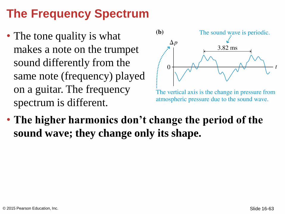
• The tone quality is what
makes a note on the trumpet
sound differently from the
same note (frequency) played
on a guitar. The frequency
spectrum is different.
• The higher harmonics don’t change the period of the
sound wave; they change only its shape.
© 2015 Pearson Education, Inc.

Slide 16-64
Vowels and Formants
• Speech begins with the
vibration of vocal cords,
stretched tissue in your
throat.
• Your vocal cords produce
a mix of different
frequencies as they
vibrate—the fundamental frequency and a mixture of
higher harmonics.
• This creates the pitch of your voice and can be changed by
changing the tension in your vocal cords.
© 2015 Pearson Education, Inc.

Slide 16-65
Vowels and Formants
• Sound then passes through
your vocal tract—a series of
cavities including the throat,
mouth, and nose—that act
like tubes.
• The standing-wave
resonances in the vocal tract
are called formants.
© 2015 Pearson Education, Inc.

Slide 16-66
Vowels and Formants
• You change the shape and
frequency of the formants,
and thus the sounds you
make, by changing your
mouth opening and the
shape and position of your
tongue.
© 2015 Pearson Education, Inc.

Section 16.6 The Interference of Waves from Two Sources
© 2015 Pearson Education, Inc.

Slide 16-68
Interference Along a Line
• Two loudspeakers are
spaced exactly one
wavelength apart.
Assuming the sound
waves are identical, the
waves will travel on top of
each other.
• Superposition says that for
every point along the line,
the net sound pressure will
be the sum of the
pressures.
© 2015 Pearson Education, Inc.

Slide 16-69
Interference Along a Line
• Because the loudspeakers
are spaced one wavelength
apart, the crests and
troughs are aligned, and
therefore are in phase.
• Waves that are in phase
will have constructive
interference.
© 2015 Pearson Education, Inc.

Slide 16-70
Interference Along a Line
• If d1 and d2 are the
distances from the
loudspeakers to the
observer, their difference is
called the path-length
difference.
• Two waves will be in
phase and will produce
constructive interference
any time their path-length
difference is a whole
number of wavelengths.
© 2015 Pearson Education, Inc.

Slide 16-71
Interference Along a Line
• When the speakers are
separated by half a
wavelength, the waves are
out of phase.
• The sum of the two waves
is zero at every point; this
is destructive interference.
© 2015 Pearson Education, Inc.

Slide 16-72
Interference Along a Line
• Two wavelengths will
be out of phase and will
produce destructive
interference if their
path-length difference
is a whole number of
wavelength plus half a
wavelength.
© 2015 Pearson Education, Inc.

Slide 16-73
Interference Along a Line
• For two identical sources of waves, constructive
interference occurs when the path-length difference is
• Destructive interference occurs when the path-length
difference is
© 2015 Pearson Education, Inc.

Slide 16-74
Interference Along a Line
• If two loudspeakers are side by
side, and one emits the exact
inverse of the other speaker’s
wave, then there will be
destructive interference and the
sound will completely cancel.
• Headphones with active noise
reduction measure the ambient
sound and produce an inverted
version to add to it, lowering the
overall intensity of the sound.
© 2015 Pearson Education, Inc.

Slide 16-75
Interference of Spherical Waves
• In practice, sound waves
from a speaker or light
waves emitted from a
lightbulb spread out as
spherical waves.
© 2015 Pearson Education, Inc.

Slide 16-76
Interference of Spherical Waves
• Interference occurs where
the waves overlap.
• The red dot represents a
point where two wave crests
overlap, so the interference is
constructive.
• The black dot is at a point
where a crest overlaps a
trough, so the wave
interference is destructive.
© 2015 Pearson Education, Inc.

Slide 16-77
Interference of Spherical Waves
• Counting the wave fronts,
we see that the red dot is
three wavelengths from
speaker 2 and two
wavelengths from speaker 1.
The path-length difference is
Δr = r2 – r1 = λ
• The path-length of the black
dot is Δr = ½ λ.
© 2015 Pearson Education, Inc.

Slide 16-78
• The general rule for identifying whether constructive or
destructive interference occurs is the same for spherical
waves as it is for waves traveling along a line.
• Constructive interference occurs when
• Destructive interference occurs when
Interference of Spherical Waves
© 2015 Pearson Education, Inc.

Slide 16-79
Interference of Spherical Waves
© 2015 Pearson Education, Inc.
Text: p. 519

Slide 16-80
Example 16.11 Is the sound loud or quiet?
Two speakers are 3.0 m apart
and play identical tones of
frequency 170 Hz. Sam stands
directly in front of one speaker
at a distance of 4.0 m. Is this a
loud spot or a quiet spot? Assume
that the speed of sound in air is
340 m/s.
PREPARE FIGURE 16.31 shows a visual overview of the
situation, showing the positions of and path lengths from
each speaker.
© 2015 Pearson Education, Inc.

Slide 16-81
Example 16.11 Is the sound loud or quiet? (cont.)
SOLVE Following the steps in
Tactics Box 16.1, we first
compute the path-length
difference. r1, r2, and the
distance between the speakers
form a right triangle, so we can
use the Pythagorean theorem to find
Thus the path-length difference is
∆r = r2 r1 = 1.0 m
© 2015 Pearson Education, Inc.

Slide 16-82
Example 16.11 Is the sound loud or quiet? (cont.)
Next, we compute the wavelength:
The path-length difference is λ, so this is a point of
destructive interference. Sam is at a quiet spot.
© 2015 Pearson Education, Inc.

Slide 16-83
Example Problem
Two speakers emit identical sinusoidal waves. The speakers
are placed 4.0 m apart. A listener moving along a line in
front of the two speakers finds loud and quiet spots as
shown in the following figure. The grid lines are spaced at
1.0 m. What is the frequency of the sound from the two
speakers?
© 2015 Pearson Education, Inc.

Section 16.7 Beats
© 2015 Pearson Education, Inc.

Slide 16-85
Beats
• The superposition of two waves with slightly different
frequencies can create a wave whose amplitude shows a
periodic variation.
© 2015 Pearson Education, Inc.

Slide 16-86
Beats
• The ear hears a single tone that is modulated. The
distinctive sound pattern is called beats.
© 2015 Pearson Education, Inc.

Slide 16-87
Beats
• The air oscillates against your
eardrum at frequency
• The beat frequency is the
difference between two
frequencies that differ slightly:
• fosc determines the pitch, fbeat determines the frequency of
the modulations.
© 2015 Pearson Education, Inc.

Slide 16-88
Summary: General Principles
© 2015 Pearson Education, Inc. Text: p. 523

Slide 16-89
Summary: General Principles
© 2015 Pearson Education, Inc.
Text: p. 523

Slide 16-90
Summary: Important Concepts
© 2015 Pearson Education, Inc.
Text: p. 523

Slide 16-91
Summary: Important Concepts
© 2015 Pearson Education, Inc.
Text: p. 523

Slide 16-92
Summary: Important Concepts
© 2015 Pearson Education, Inc.
Text: p. 523

Slide 16-93
Summary: Applications
© 2015 Pearson Education, Inc.
Text: p. 523

Slide 16-94
Summary: Applications
© 2015 Pearson Education, Inc.
Text: p. 523

Slide 16-95
Summary
© 2015 Pearson Education, Inc.
Text: p. 523

Slide 16-96
Summary
© 2015 Pearson Education, Inc.
Text: p. 523

Slide 16-97
Summary
© 2015 Pearson Education, Inc.
Text: p. 523