lecture 2 review - trinity college, dublin · lecture objectives •linear circuit •superposition...
TRANSCRIPT

Lecture 2 Review
• Methods of Analysis
—Nodal analysis
• Without Voltage Sources
• With Voltage Sources
—Mesh analysis
• Without Current Sources
• With Coltage Sources
—Analysis by Inspection

Quiz
An open-loop gain: 2105
Input resistance: 2 M Output resistance: 50 Find the closed-loop gain:
s
o
v
v

Lecture 3 DC Circuits Circuit Theorems: to simplify circuit analysis

Lecture Objectives
• Linear circuit
• Superposition
• Equivalent Circuits
—Simple Circuits
—Y- Transforms
—Source transformation
—Thevenin's theorem
—Norton's theorem
• Maximum power transfer

Linear circuit
Linear Circuit Input(excitation),i Output(response), v
• Linearity Property
—Homogeneity:
—Additivity:
iRv
000101 )( , kvRikRkivkii
21212121 )( , vvRiRiRiiviii

Example: Linearity
Assume I0 = 1 A,… the source current Is =? 5 A
Since Is = 15 A = 3 × 5A, according to linearity (homogeneity), I0 = ? 3 A
3V
5V
8V
1A 2A
3A
6V
14V
2A
5A

Superposition: several sources
• Linear circuit: Additivity
• Voltage or Current = algebraic sum of v or i due to each independent source acting alone, respectively.
• Can we use superposition for power? No! Why?
If there are N sources, you’ll need to do similar calculation N times.

Example: Superposition
Use the superposition theorem to find v in the circuit:
v = 10 V
Voltage source 0 V Short circuit
Current source 0 A Open circuit
Turn off
How about dependent sources?

Equivalence of circuits
• Series-parallel combination • Y- transformation • Source Transformation • Thevenin’s Theorem • Norton’s Theorem
a
b
What elements are in the box?
What is the behaviour of the circuit? Voltage-Current relation
Voltage-current relation at terminals a and b is identical to that of its equivalent circuit.
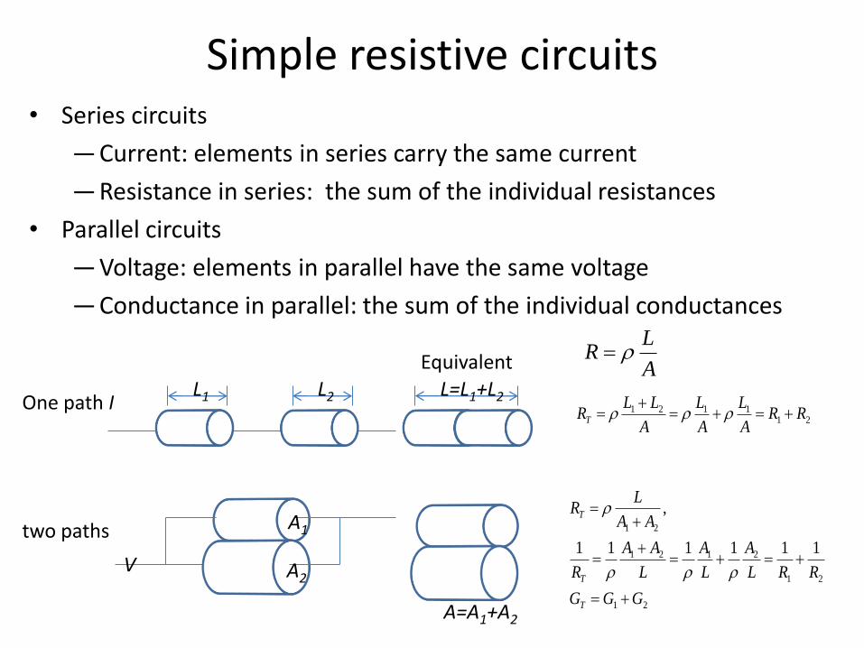
• Series circuits
— Current: elements in series carry the same current
— Resistance in series: the sum of the individual resistances
• Parallel circuits
— Voltage: elements in parallel have the same voltage
— Conductance in parallel: the sum of the individual conductances
Simple resistive circuits
A
LR
One path I L2 L1
211121 RR
A
L
A
L
A
LLRT
two paths
A=A1+A2
A1
A2
21
21
2121
21
111111
,
GGG
RRL
A
L
A
L
AA
R
AA
LR
T
T
T
V
L=L1+L2
Equivalent
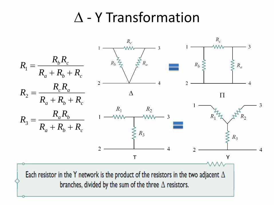
- Y Transformation
cba
ba
cba
ac
cba
cb
RRR
RRR
RRR
RRR
RRR
RRR
3
2
1
Y T

Y- Transformation

Example
Obtain the equivalent resistance Rab for the circuit and use it to find current i

Source transformation
SouceCurrent A Source VoltageA
Check: Voltage Source Current Source Turn-off source R
Open Circuit
Short Circuit
sv Ris
R
vs
si
Replacing a voltage source vs in series with a resistor R by a current source is in parallel with a resistor R, or vice versa.
R
R
That’s what the external sources ‘feel’
this part of the circuit. That’s how this part of circuit acts on
the load as a ’source’.

Example
Use source transformation to find vo in the circuit

Thevenin's theorem
Other elements - fixed
Load – variable
Vth : Open circuit voltage
RTh : the input resistance at the terminals when the independent sources are turned off

Example
Find the Thevenin equivalent circuit of the circuit, to the left of the terminals a-b. Then find the current through RL = 6, 16, and 36

Norton's theorem

Maximum power transfer
• Minimizing power dissipated in the process of transmission and distribution • Maximize the power delivered to a load
LRip 2LTh
Th
RR
Vi
L
LTh
ThL R
RR
VRip
2
2

Apendix

Op Amp - typical packages
Looking from the top
Pin 1 is always to the left of the notch or dot.
741 General-purpose: Fairchild Semiconductor … Intel
For package information: http://www.intersil.com/design/packages/
1. An active circuit element 2. Perform mathematical
operations

Feedback path - example
An open-loop gain: 2105
Input resistance: 2 M Output resistance: 50 Find the closed-loop gain:
s
o
v
v
Nodal analysis
Feedback: negative feedback
9999699.1s
o
v
v
Insensitive to A
This is tedious.

Ideal Op Amp
• Infinite open-loop gain, • Infinite input resistance, • Zero output resistance,
A
iR
0oR
Virtual open circuit i1 = i2 =0
Virtual close circuit vd = 0; v1 = v2

Idea Op Amp - Example
Rework it using the ideal op amp model
v1
v2
3
1
3
1
10201010
os vvvv
021 vv
2
1020
0
1010
033
s
o
os
v
v
vv
9999699.1s
o
v
v
Working with non-ideal: Negligibly small error results from assuming ideal op amp characteristics Virtual open circuit: i1 = i2 =0 Virtual close circuit: vd = 0; v1 = v2
i2 =0
i1 =0
Node 1:
Idea Op Amp: 021 ii
Idea Op Amp:

Lecture 4 DC Circuits Capacitors and Inductors