lecture 5-2: sequential circuit design continued
TRANSCRIPT

Lecture 5-2: Sequential Circuit Design continued
FSM design
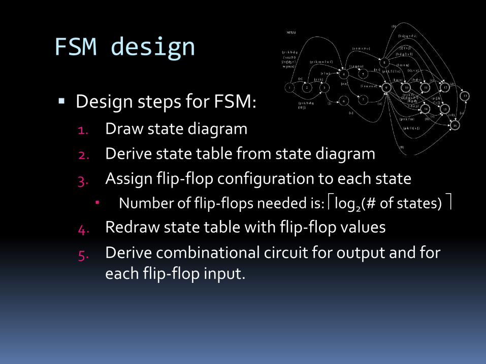
§ Design steps for FSM:1. Draw state diagram2. Derive state table from state diagram3. Assign flip-flop configuration to each state
Number of flip-flops needed is: élog2(# of states) ù4. Redraw state table with flip-flop values5. Derive combinational circuit for output and for
each flip-flop input.

State diagrams with output
§ Output values are incorporated into the state diagram, depending on the type of machine.
A/0 B/11
Input(s)State/ Output(s)
ØMoore Machine
C D1/0
Input(s) / Output(s)State
ØMealy Machine
Example #4: Sequence Recognizer
§ Recognize a sequence of input values, and raise a signal if that input has been seen.
§ Example: Three high values in a rowú Understood to mean that the input has been high
for three rising clock edges.ú Assumes a single input IN and a single output Z.
Step 1: State diagram
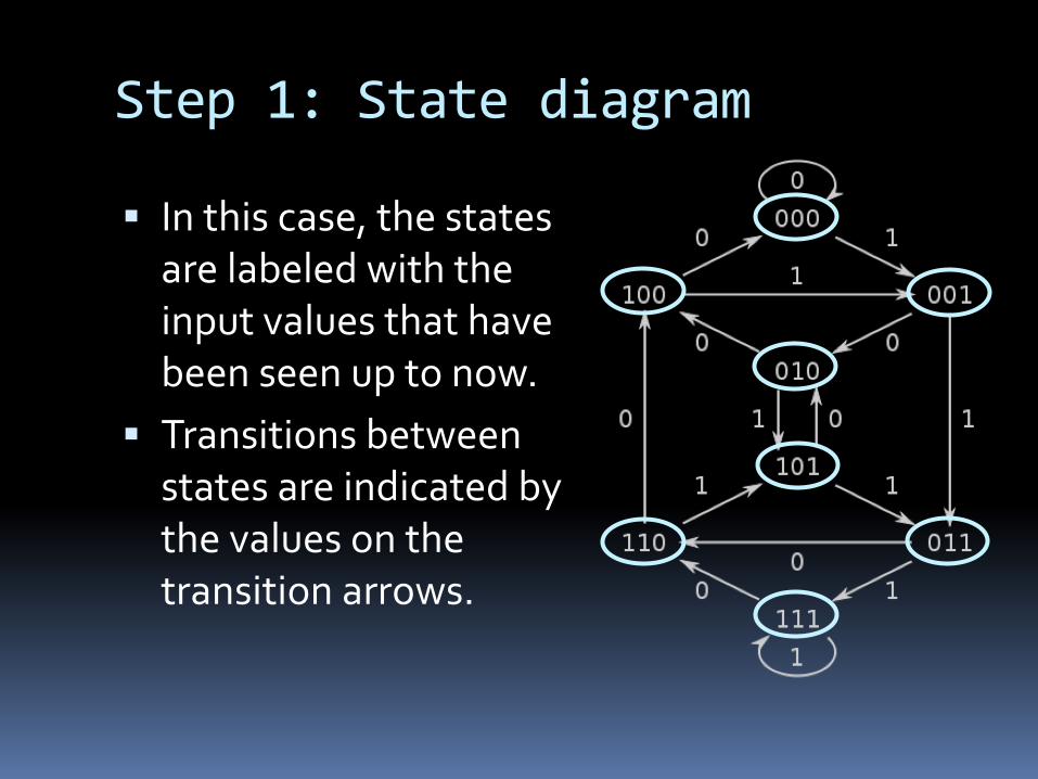
§ In this case, the states are labeled with the input values that have been seen up to now.
§ Transitions between states are indicated by the values on the transition arrows.
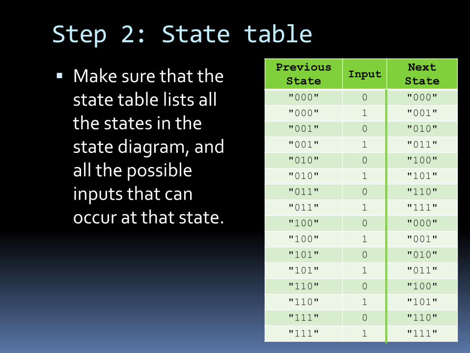
Step 2: State table§ Make sure that the
state table lists all the states in the state diagram, and all the possible inputs that can occur at that state.
Previous State
InputNext State
"000" 0 "000"
"000" 1 "001"
"001" 0 "010"
"001" 1 "011"
"010" 0 "100"
"010" 1 "101"
"011" 0 "110"
"011" 1 "111"
"100" 0 "000"
"100" 1 "001"
"101" 0 "010"
"101" 1 "011"
"110" 0 "100"
"110" 1 "101"
"111" 0 "110"
"111" 1 "111"
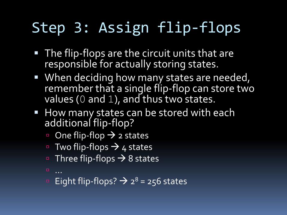
Step 3: Assign flip-flops§ The flip-flops are the circuit units that are
responsible for actually storing states.§ When deciding how many states are needed,
remember that a single flip-flop can store two values (0 and 1), and thus two states.
§ How many states can be stored with each additional flip-flop?ú One flip-flop à 2 statesú Two flip-flops à 4 statesú Three flip-flops à 8 statesú …ú Eight flip-flops? à 28 = 256 states
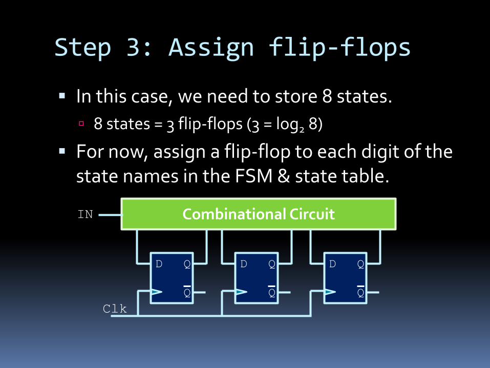
Step 3: Assign flip-flops
§ In this case, we need to store 8 states.ú 8 states = 3 flip-flops (3 = log2 8)
§ For now, assign a flip-flop to each digit of the state names in the FSM & state table.
D Q
Q
Combinational Circuit
D Q
Q
D Q
QClk
IN
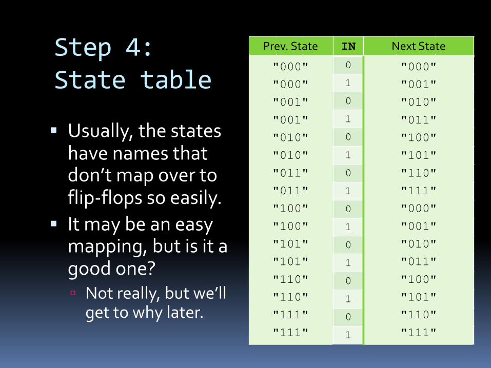
Step 4: State table
§ Usually, the states have names that don’t map over to flip-flops so easily.
§ It may be an easy mapping, but is it a good one?ú Not really, but we’ll
get to why later.
F2 F1 F0 IN F2 F1 F00 0 0 0 0 0 0
0 0 0 1 0 0 1
0 0 1 0 0 1 0
0 0 1 1 0 1 1
0 1 0 0 1 0 0
0 1 0 1 1 0 1
0 1 1 0 1 1 0
0 1 1 1 1 1 1
1 0 0 0 0 0 0
1 0 0 1 0 0 1
1 0 1 0 0 1 0
1 0 1 1 0 1 1
1 1 0 0 1 0 0
1 1 0 1 1 0 1
1 1 1 0 1 1 0
1 1 1 1 1 1 1
"000"
"000"
"001"
"001"
"010"
"010"
"011"
"011"
"100"
"100"
"101"
"101"
"110"
"110"
"111"
"111"
Prev. State
"000"
"001"
"010"
"011"
"100"
"101"
"110"
"111"
"000"
"001"
"010"
"011"
"100"
"101"
"110"
"111"
Next State
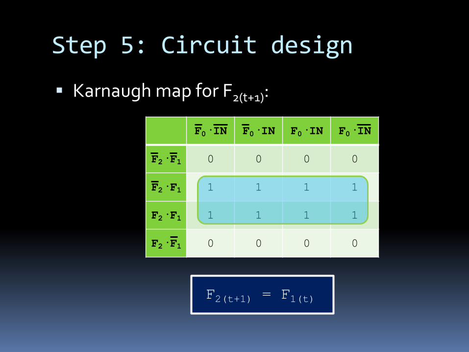
Step 5: Circuit design
§ Karnaugh map for F2(t+1):
F0·IN F0·IN F0·IN F0·IN
F2·F1 0 0 0 0
F2·F1 1 1 1 1
F2·F1 1 1 1 1
F2·F1 0 0 0 0
F2(t+1) = F1(t)
Step 5: Circuit design
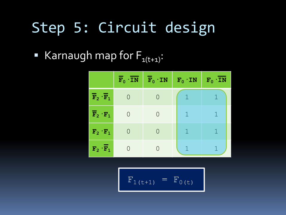
§ Karnaugh map for F1(t+1):
F0·IN F0·IN F0·IN F0·IN
F2·F1 0 0 1 1
F2·F1 0 0 1 1
F2·F1 0 0 1 1
F2·F1 0 0 1 1
F1(t+1) = F0(t)
Step 5: Circuit design
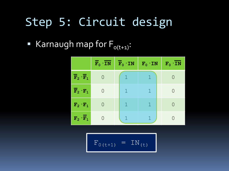
§ Karnaugh map for F0(t+1):
F0·IN F0·IN F0·IN F0·IN
F2·F1 0 1 1 0
F2·F1 0 1 1 0
F2·F1 0 1 1 0
F2·F1 0 1 1 0
F0(t+1) = IN(t)
Step 5: Circuit design
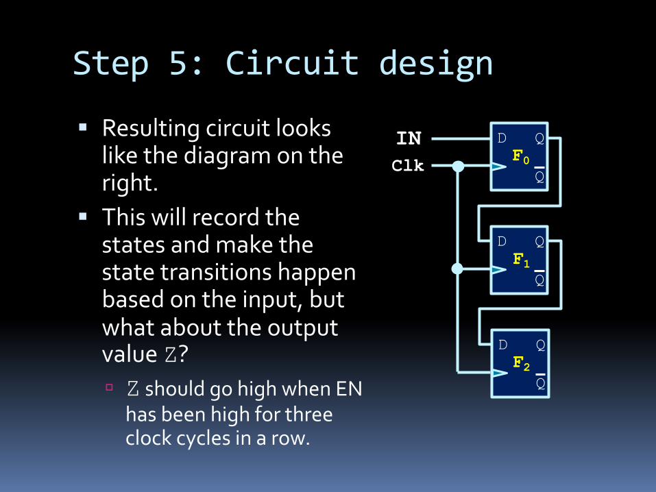
§ Resulting circuit looks like the diagram on the right.
§ This will record the states and make the state transitions happen based on the input, but what about the output value Z?ú Z should go high when EN
has been high for three clock cycles in a row.
D Q
Q
D Q
Q
D Q
QF0
F1
F2
INClk
Step 5: Circuit design
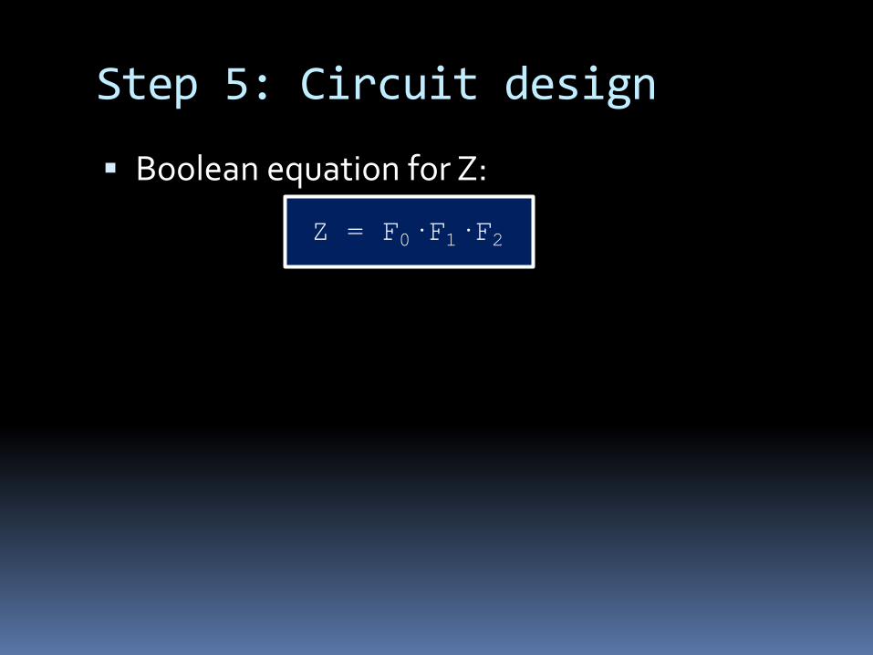
§ Boolean equation for Z:
Z = F0·F1·F2

FSM design
§ Design steps for FSM:1. Draw state diagram2. Derive state table from state diagram3. Assign flip-flop configuration to each state
Number of flip-flops needed is: élog2(# of states) ù4. Redraw state table with flip-flop values5. Derive combinational circuit for output and for
each flip-flop input.
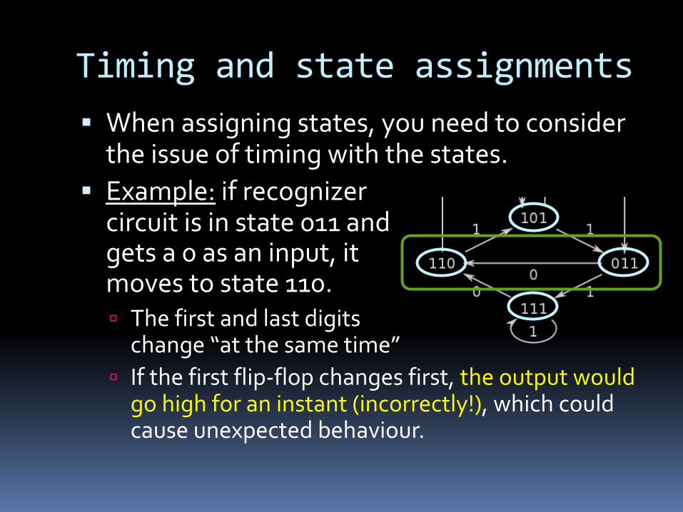
Timing and state assignments§ When assigning states, you need to consider
the issue of timing with the states.§ Example: if recognizer
circuit is in state 011 andgets a 0 as an input, itmoves to state 110.ú The first and last digits
change “at the same time”ú If the first flip-flop changes first, the output would
go high for an instant (incorrectly!), which could cause unexpected behaviour.
Timing and state assignments§ So how do you solve this?§ Possible solutions:
1. Whenever possible, make flip-flop assignments such that neighbouring states differ by at most one flip-flop value (state encoding differs by one bit).
2. If “intermediate” state output is the same as starting or destination state à no problem
3. Add intermediate transition states between start and end
1. Use unused flip-flop states or may need to add more

Question #4§ How would we make the following Finite
State Machine?

Example #5§ Exploding Pen
ú Starts disarmedú 3 clicks to armú 3 clicks to disarm
§ https://youtu.be/Vi4LmILZU0g
ú Note: Please do not use the knowledge you've gained in this course to develop exploding pens.
ú Note 2: If you do, please don't use them for evil