sequential circuit design with verilog - uc santa barbara - sequential circuit...sequential circuit...
TRANSCRIPT
Sequential Circuit Design with Verilog
ECE 152A – Winter 2012
February 15, 2012 ECE 152A - Digital Design Principles 2
Reading Assignment
Brown and Vranesic 6 Combinational – Circuit Building Blocks
6.6 Verilog for Combinational Circuits 6.6.1 The Conditional Operator 6.6.2 The If-Else Statement 6.6.3 The Case Statement

February 15, 2012 ECE 152A - Digital Design Principles 3
Reading Assignment
Brown and Vranesic (cont) 7 Flip-Flops, Registers, Counters, and a Simple
Processor 7.12 Using Storage Elements with CAD Tools
7.12.2 Using Verilog Constructs for Storage Elements 7.12.3 Blocking and Non-Blocking Assignments 7.12.4 Non-Blocking Assignments for Combinational
Circuits 7.12.5 Flip-Flops with Clear Capability
7.13 Using Registers and Counters with CAD Tools 7.13.3 Using Verilog Constructs for Registers and Counters
February 15, 2012 ECE 152A - Digital Design Principles 4
The Gated D Latch
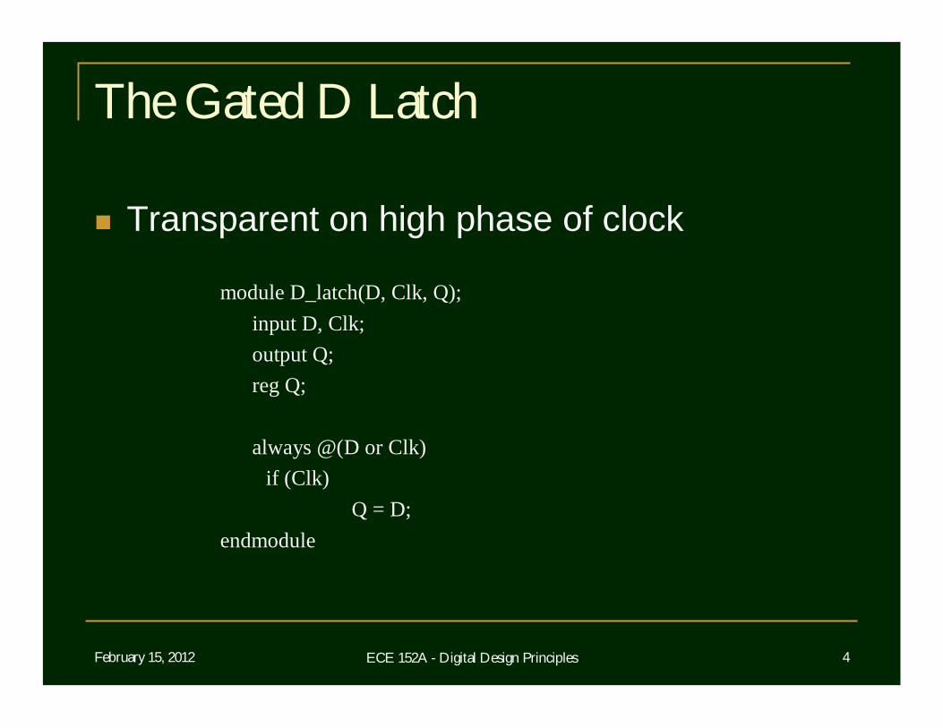
Transparent on high phase of clock
module D_latch(D, Clk, Q);input D, Clk;output Q;reg Q;
always @(D or Clk)if (Clk)
Q = D;endmodule
February 15, 2012 ECE 152A - Digital Design Principles 5
The Gated D Latch
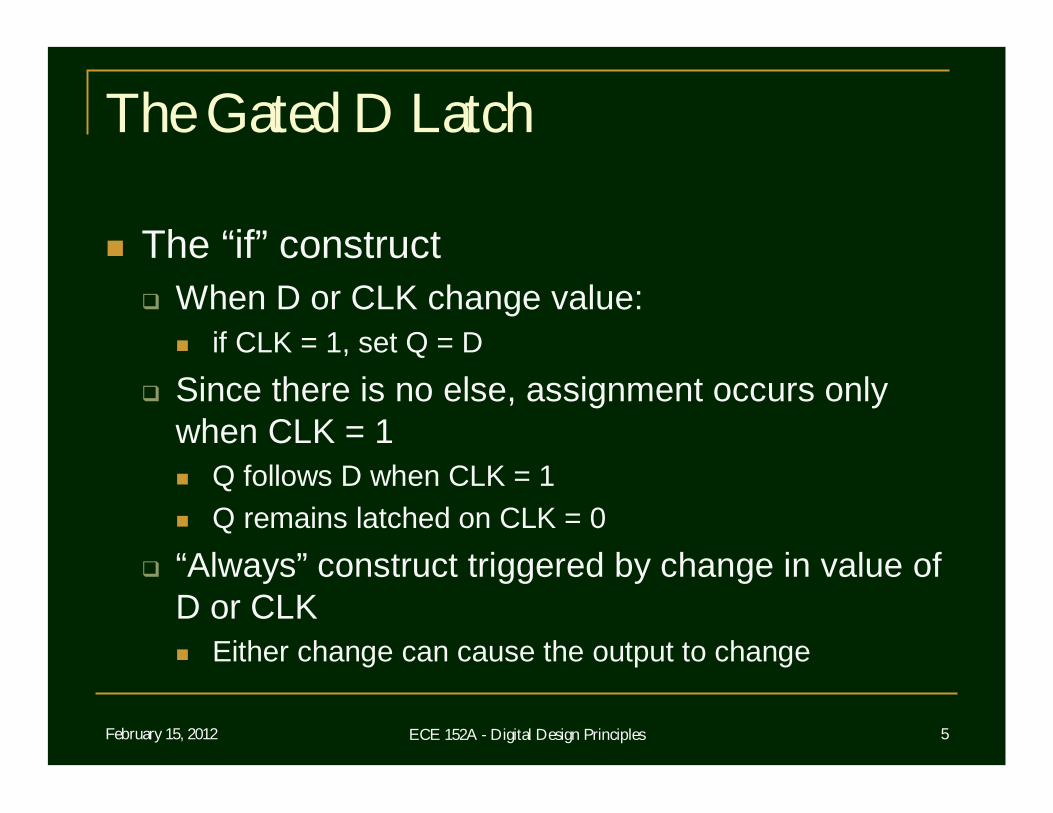
The “if” construct When D or CLK change value:
if CLK = 1, set Q = D Since there is no else, assignment occurs only
when CLK = 1 Q follows D when CLK = 1 Q remains latched on CLK = 0
“Always” construct triggered by change in value of D or CLK Either change can cause the output to change
February 15, 2012 ECE 152A - Digital Design Principles 6
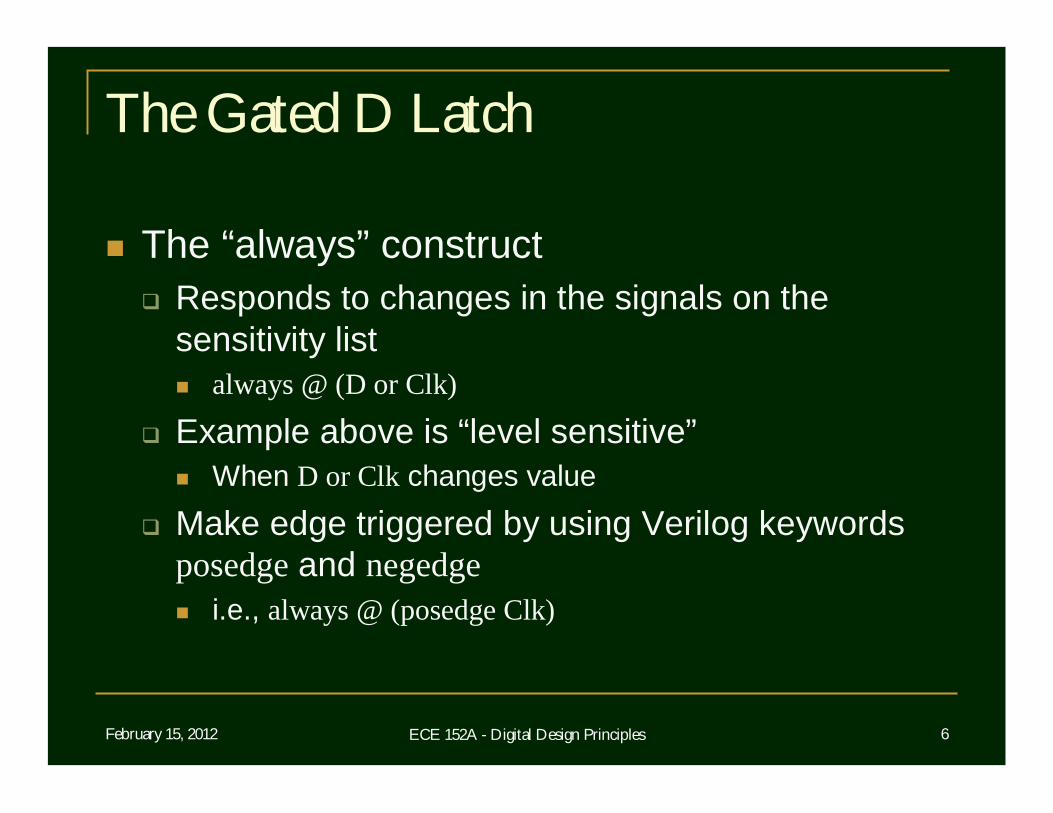
The Gated D Latch
The “always” construct Responds to changes in the signals on the
sensitivity list always @ (D or Clk)
Example above is “level sensitive” When D or Clk changes value
Make edge triggered by using Verilog keywords posedge and negedge i.e., always @ (posedge Clk)
February 15, 2012 ECE 152A - Digital Design Principles 7
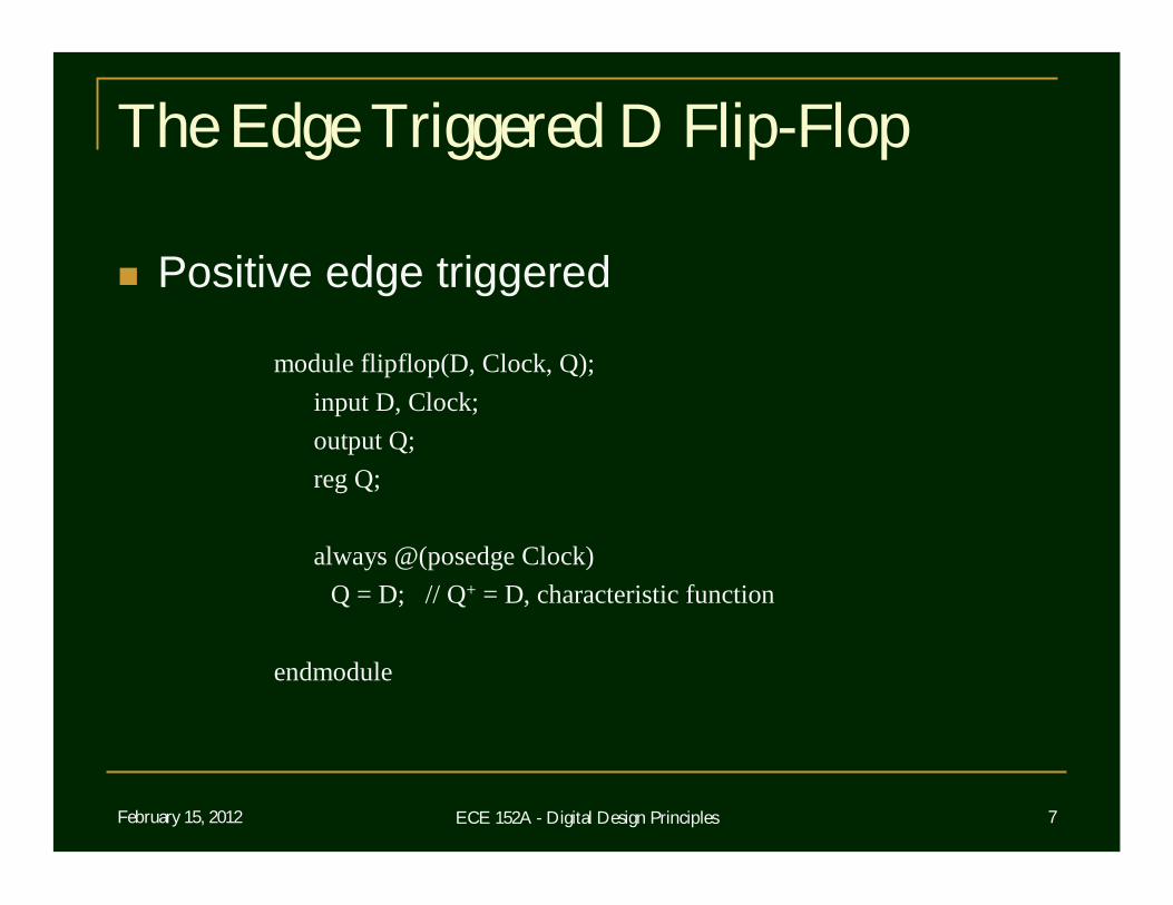
The Edge Triggered D Flip-Flop
Positive edge triggered
module flipflop(D, Clock, Q);input D, Clock;output Q;reg Q;
always @(posedge Clock)Q = D; // Q+ = D, characteristic function
endmodule
February 15, 2012 ECE 152A - Digital Design Principles 8
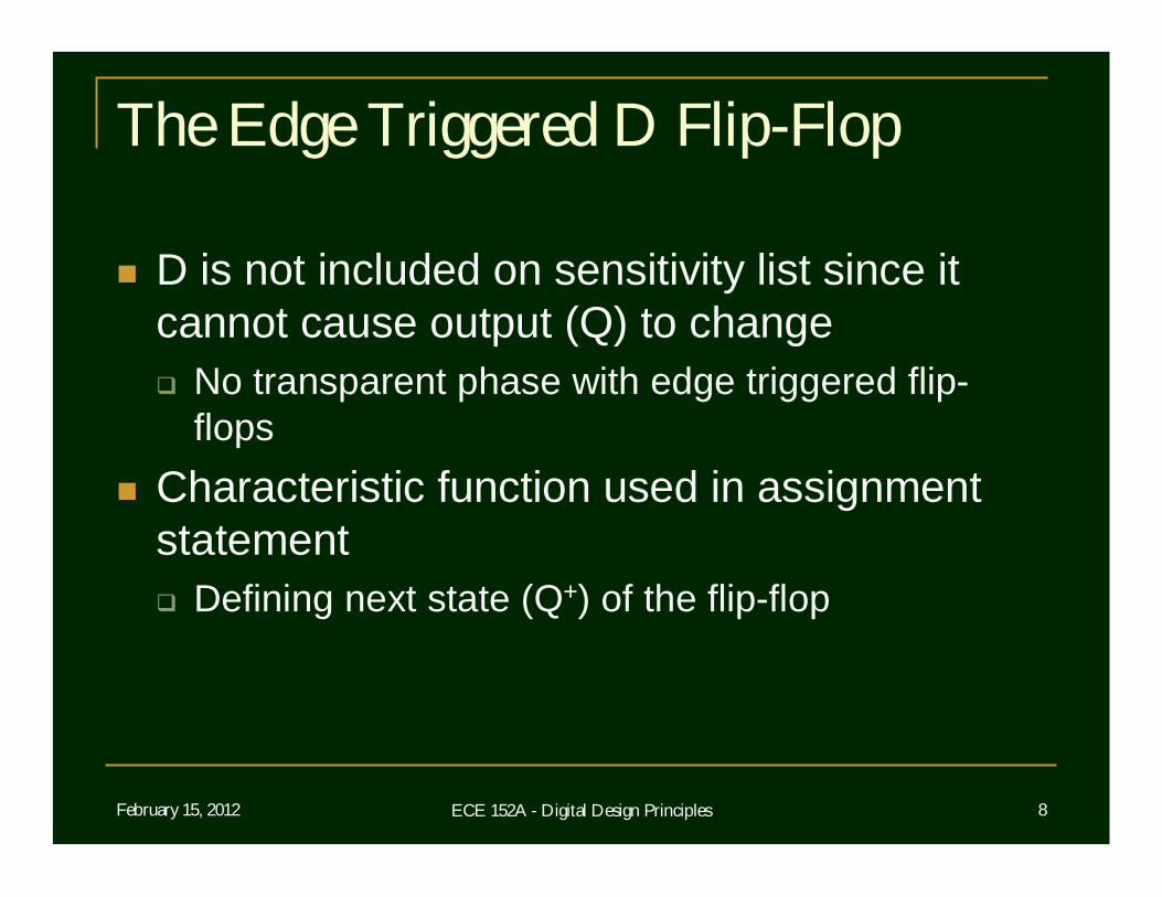
The Edge Triggered D Flip-Flop
D is not included on sensitivity list since it cannot cause output (Q) to change No transparent phase with edge triggered flip-
flops Characteristic function used in assignment
statement Defining next state (Q+) of the flip-flop
February 15, 2012 ECE 152A - Digital Design Principles 9
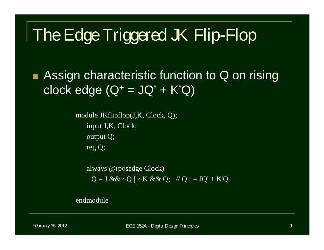
The Edge Triggered JK Flip-Flop
Assign characteristic function to Q on rising clock edge (Q+ = JQ’ + K’Q)
module JKflipflop(J,K, Clock, Q);input J,K, Clock;output Q;reg Q;
always @(posedge Clock)Q = J && ~Q || ~K && Q; // Q+ = JQ' + K'Q
endmodule
February 15, 2012 ECE 152A - Digital Design Principles 10
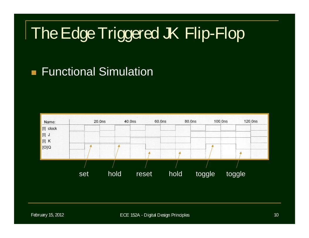
The Edge Triggered JK Flip-Flop
Functional Simulation
set hold reset hold toggle toggle
February 15, 2012 ECE 152A - Digital Design Principles 11
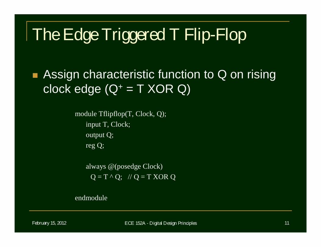
The Edge Triggered T Flip-Flop
Assign characteristic function to Q on rising clock edge (Q+ = T XOR Q)
module Tflipflop(T, Clock, Q);input T, Clock;output Q;reg Q;
always @(posedge Clock)Q = T ^ Q; // Q = T XOR Q
endmodule
February 15, 2012 ECE 152A - Digital Design Principles 12
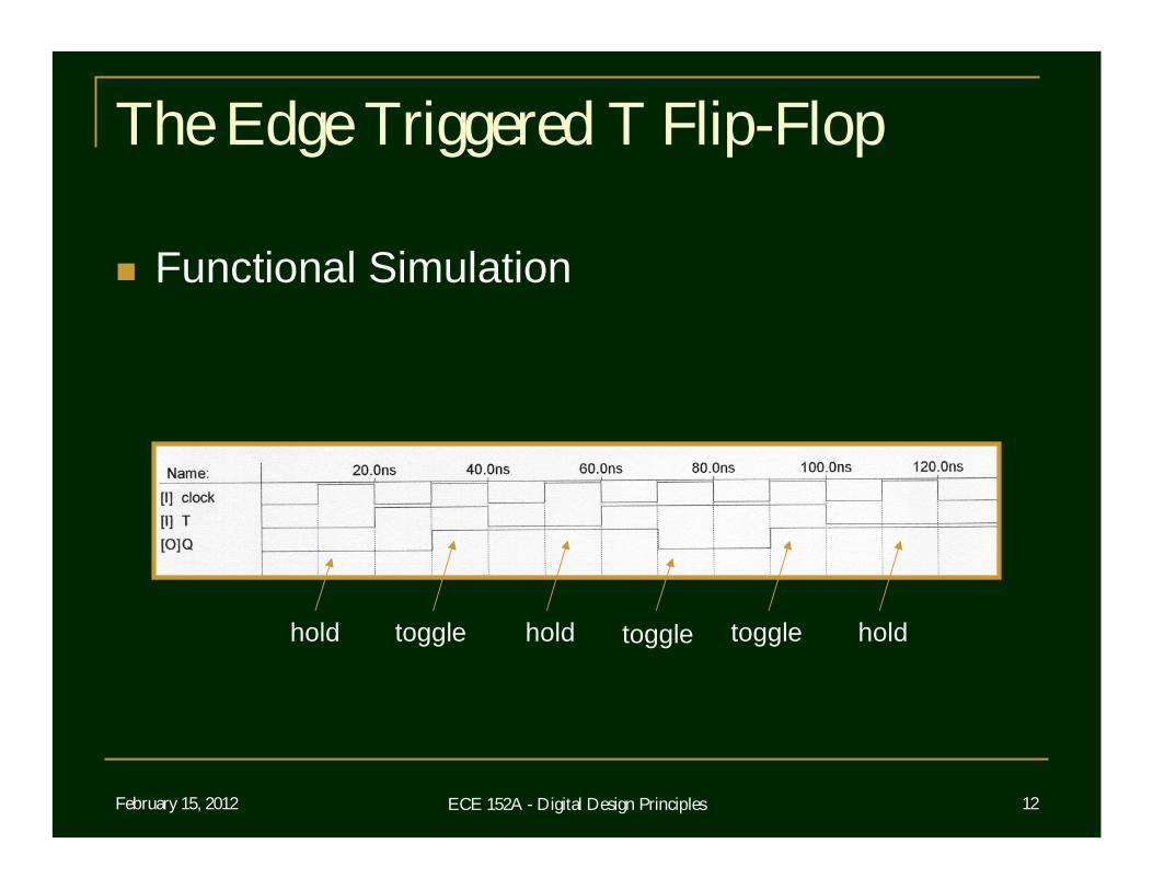
The Edge Triggered T Flip-Flop
Functional Simulation
hold toggle hold toggle toggle hold
February 15, 2012 ECE 152A - Digital Design Principles 13
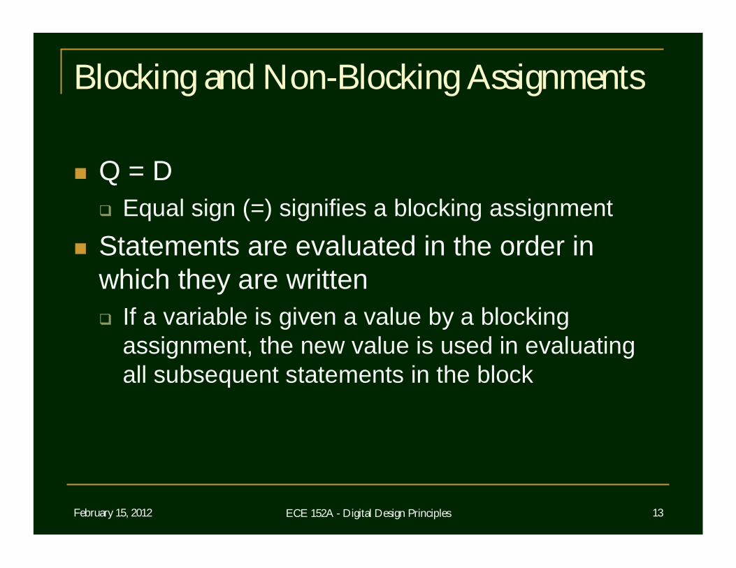
Blocking and Non-Blocking Assignments
Q = D Equal sign (=) signifies a blocking assignment
Statements are evaluated in the order in which they are written If a variable is given a value by a blocking
assignment, the new value is used in evaluating all subsequent statements in the block
February 15, 2012 ECE 152A - Digital Design Principles 14
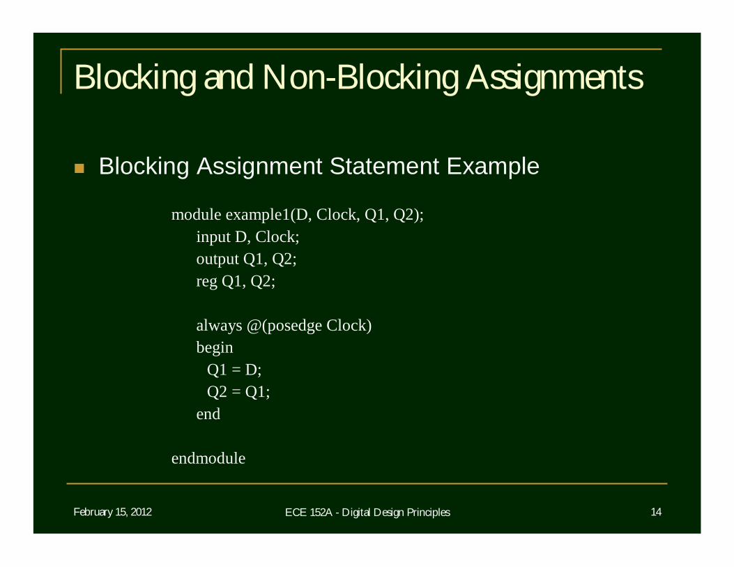
Blocking and Non-Blocking Assignments
Blocking Assignment Statement Example
module example1(D, Clock, Q1, Q2);input D, Clock;output Q1, Q2;reg Q1, Q2;
always @(posedge Clock)begin
Q1 = D;Q2 = Q1;
end
endmodule
February 15, 2012 ECE 152A - Digital Design Principles 15
Blocking and Non-Blocking Assignments
Example synthesizes two positive edge triggered D flip-flops Both flip-flops triggered by same clock edge
Both assignments in always block are blocking Q1 gets the value D Q2 then gets the new value of Q1
Q1+, which is now D
February 15, 2012 ECE 152A - Digital Design Principles 16
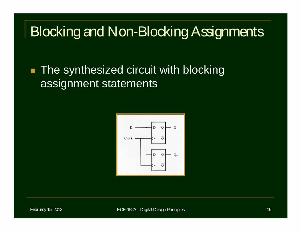
Blocking and Non-Blocking Assignments
The synthesized circuit with blocking assignment statements
February 15, 2012 ECE 152A - Digital Design Principles 17
Blocking and Non-Blocking Assignments
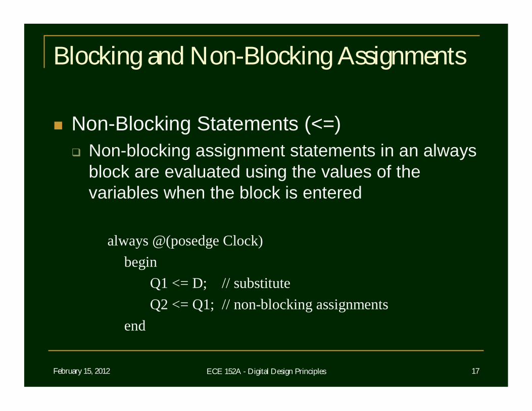
Non-Blocking Statements (<=) Non-blocking assignment statements in an always
block are evaluated using the values of the variables when the block is entered
always @(posedge Clock)begin
Q1 <= D; // substituteQ2 <= Q1; // non-blocking assignments
end
February 15, 2012 ECE 152A - Digital Design Principles 18
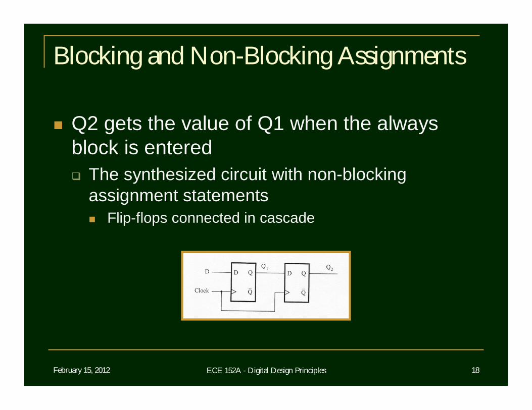
Blocking and Non-Blocking Assignments
Q2 gets the value of Q1 when the always block is entered The synthesized circuit with non-blocking
assignment statements Flip-flops connected in cascade
February 15, 2012 ECE 152A - Digital Design Principles 19
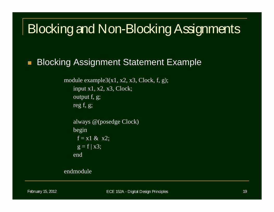
Blocking and Non-Blocking Assignments
Blocking Assignment Statement Example
module example3(x1, x2, x3, Clock, f, g);input x1, x2, x3, Clock;output f, g;reg f, g;
always @(posedge Clock)begin
f = x1 & x2;g = f | x3;
end
endmodule
February 15, 2012 ECE 152A - Digital Design Principles 20
Blocking and Non-Blocking Assignments
Both f and g are implemented as the outputs of D flip-flops Synthesized as flip-flops because the sensitivity
list of the always block specifies posedge Clock “g” gets the new value (Q+) of “f” OR’d with x3
February 15, 2012 ECE 152A - Digital Design Principles 21
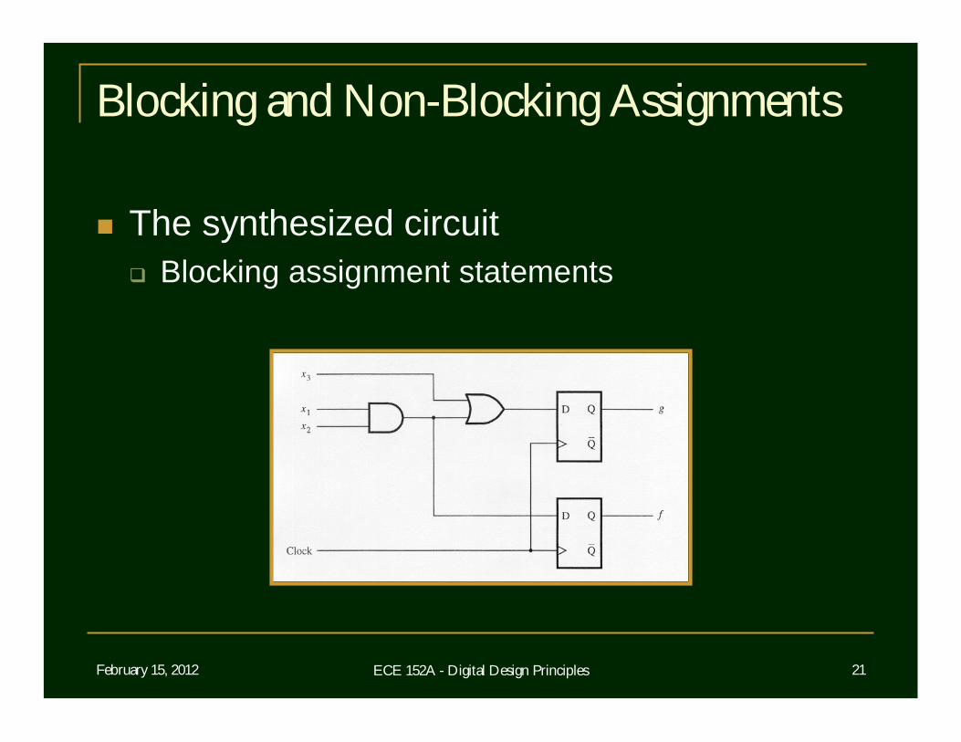
Blocking and Non-Blocking Assignments
The synthesized circuit Blocking assignment statements
February 15, 2012 ECE 152A - Digital Design Principles 22
Blocking and Non-Blocking Assignments
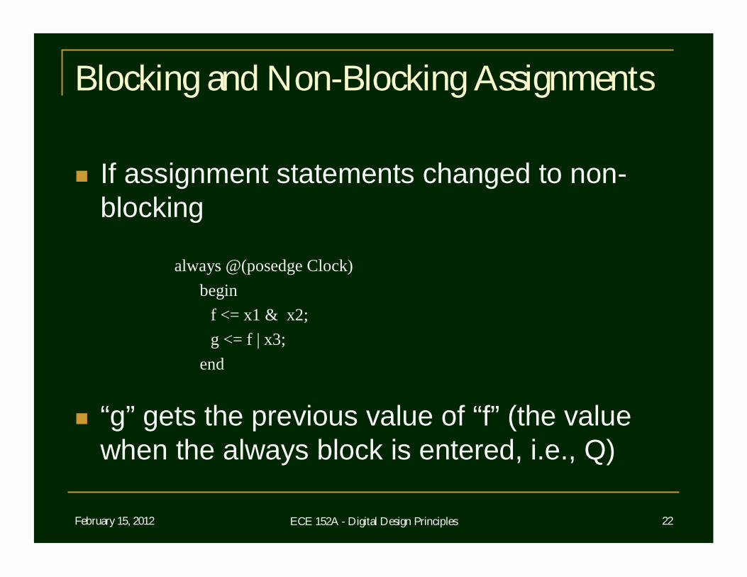
If assignment statements changed to non-blocking
always @(posedge Clock)begin
f <= x1 & x2;g <= f | x3;
end
“g” gets the previous value of “f” (the value when the always block is entered, i.e., Q)
February 15, 2012 ECE 152A - Digital Design Principles 23
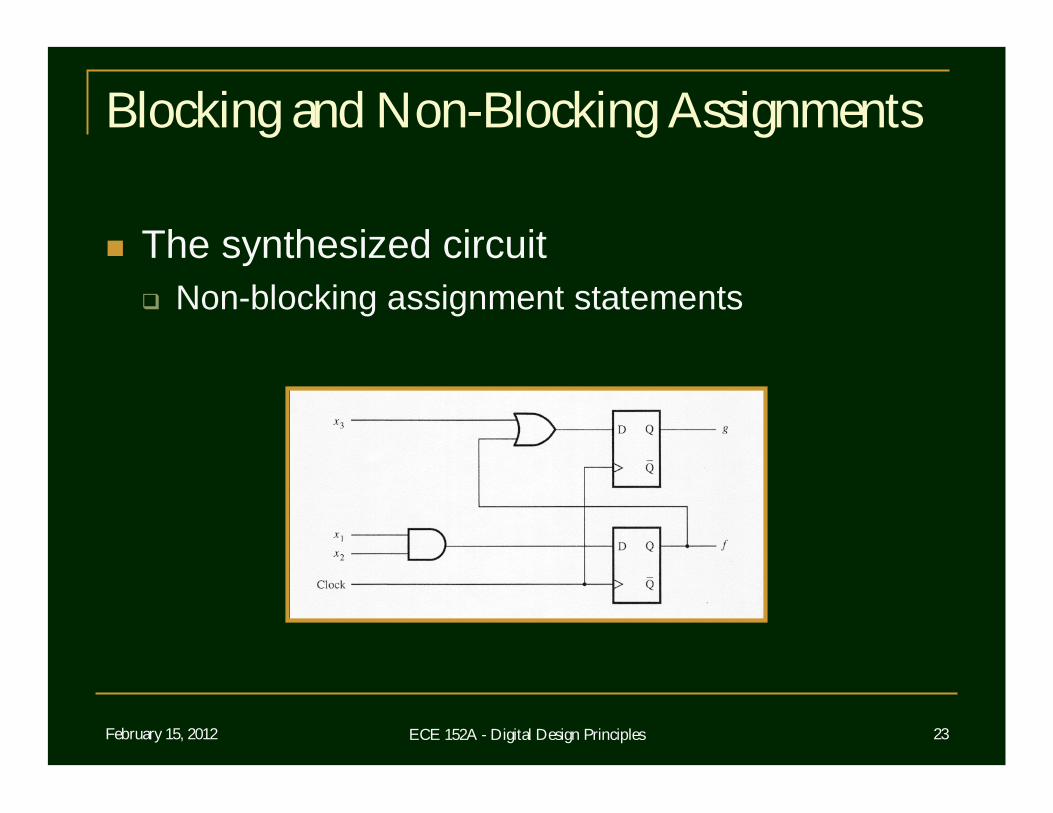
Blocking and Non-Blocking Assignments
The synthesized circuit Non-blocking assignment statements
February 15, 2012 ECE 152A - Digital Design Principles 24
Blocking and Non-Blocking Assignments
General Rule The results of non-blocking assignments are
visible only after all of the statements in the always block have been evaluated
When there are multiple assignments to the same variable inside an always block, the result of the last assignment is maintained
February 15, 2012 ECE 152A - Digital Design Principles 25
Flip-Flops with Clear
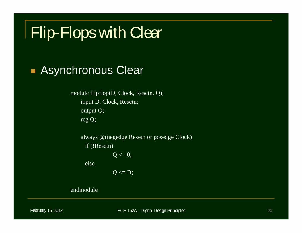
Asynchronous Clear
module flipflop(D, Clock, Resetn, Q);input D, Clock, Resetn;output Q;reg Q;
always @(negedge Resetn or posedge Clock)if (!Resetn)
Q <= 0; else
Q <= D;
endmodule
February 15, 2012 ECE 152A - Digital Design Principles 26
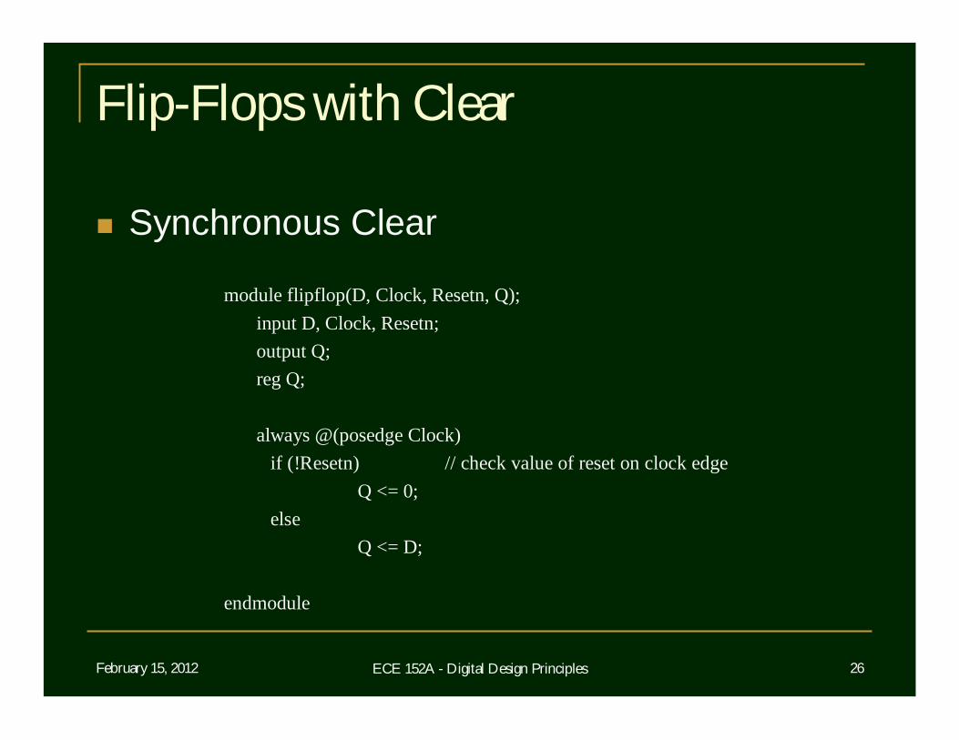
Flip-Flops with Clear
Synchronous Clear
module flipflop(D, Clock, Resetn, Q);input D, Clock, Resetn;output Q;reg Q;
always @(posedge Clock)if (!Resetn) // check value of reset on clock edge
Q <= 0;else
Q <= D;
endmodule
February 15, 2012 ECE 152A - Digital Design Principles 27
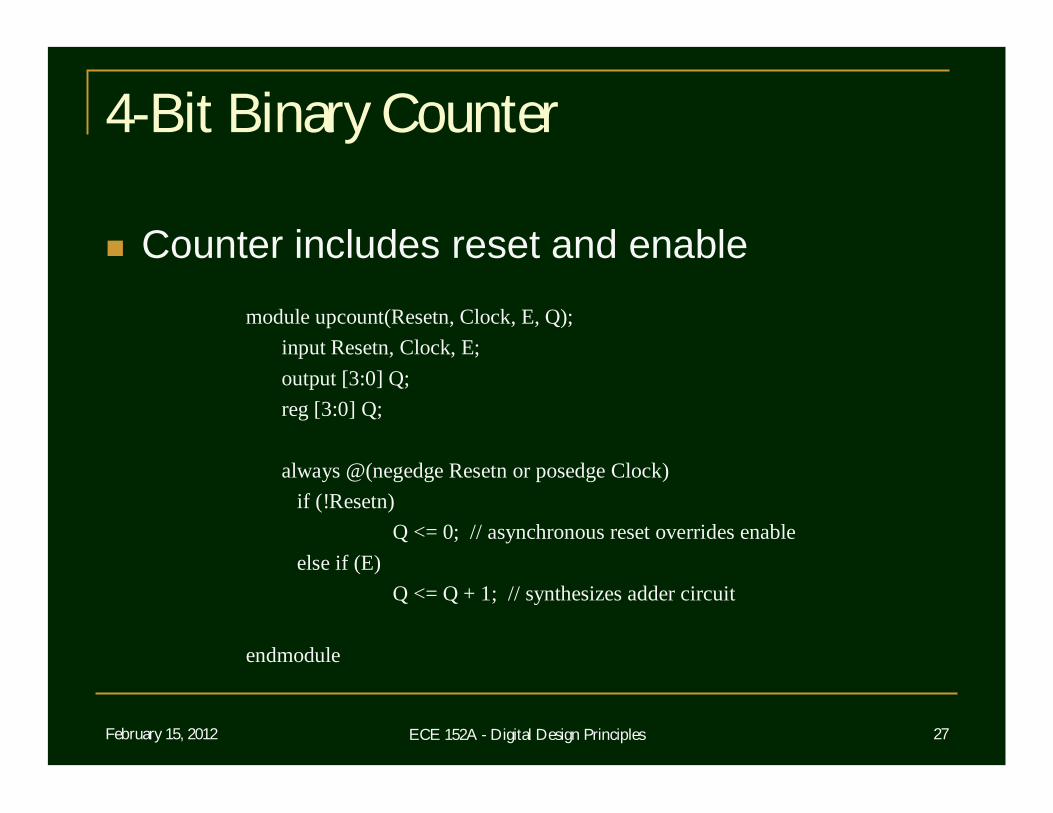
4-Bit Binary Counter
Counter includes reset and enablemodule upcount(Resetn, Clock, E, Q);
input Resetn, Clock, E;output [3:0] Q;reg [3:0] Q;
always @(negedge Resetn or posedge Clock)if (!Resetn)
Q <= 0; // asynchronous reset overrides enable else if (E)
Q <= Q + 1; // synthesizes adder circuit
endmodule
February 15, 2012 ECE 152A - Digital Design Principles 28
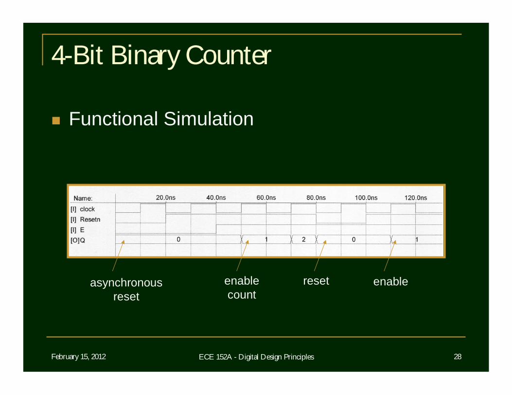
4-Bit Binary Counter
Functional Simulation
asynchronousreset
enablecount
reset enable
February 15, 2012 ECE 152A - Digital Design Principles 29
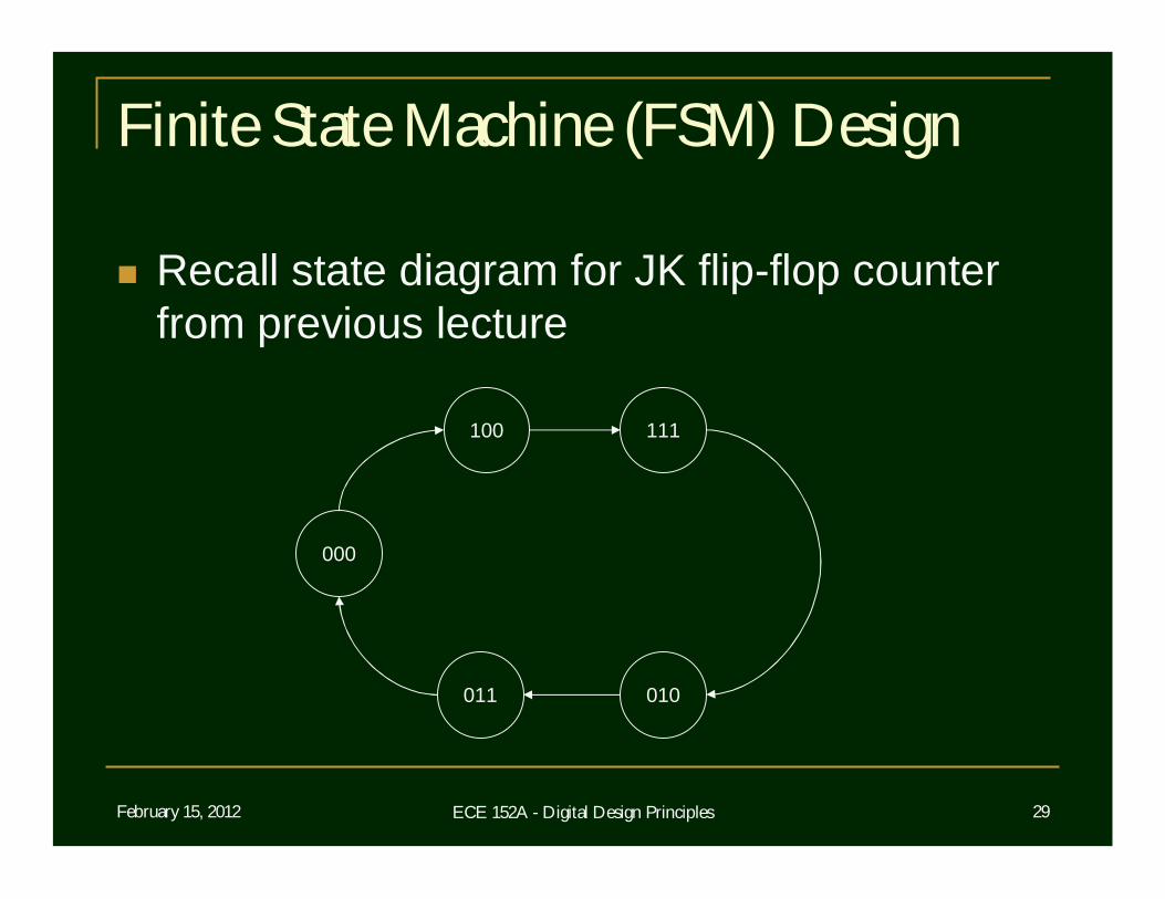
Finite State Machine (FSM) Design
Recall state diagram for JK flip-flop counter from previous lecture
100 111
011
000
010
February 15, 2012 ECE 152A - Digital Design Principles 30
Finite State Machine (FSM) Design
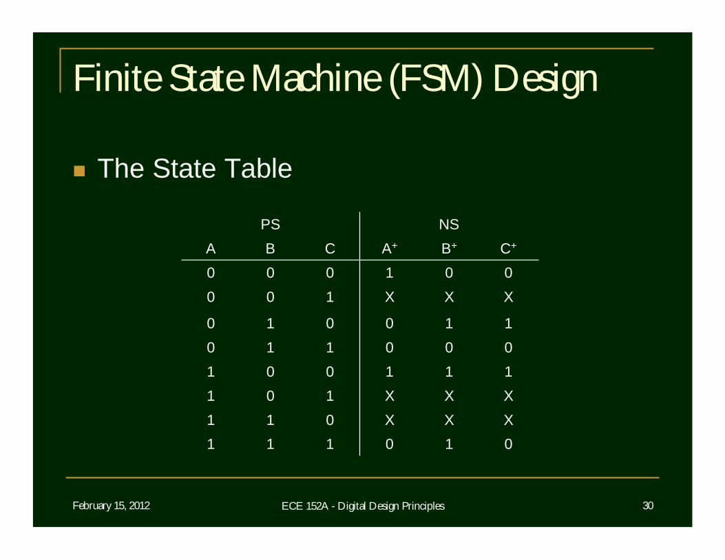
The State Table
010111XXX011XXX101111001000110110010
XXX100001000
C+B+A+CBANSPS
February 15, 2012 ECE 152A - Digital Design Principles 31
Finite State Machine (FSM) Design
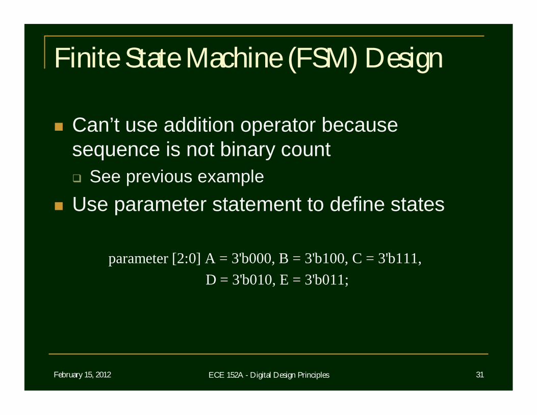
Can’t use addition operator because sequence is not binary count See previous example
Use parameter statement to define states
parameter [2:0] A = 3'b000, B = 3'b100, C = 3'b111, D = 3'b010, E = 3'b011;
February 15, 2012 ECE 152A - Digital Design Principles 32
Finite State Machine (FSM) Design
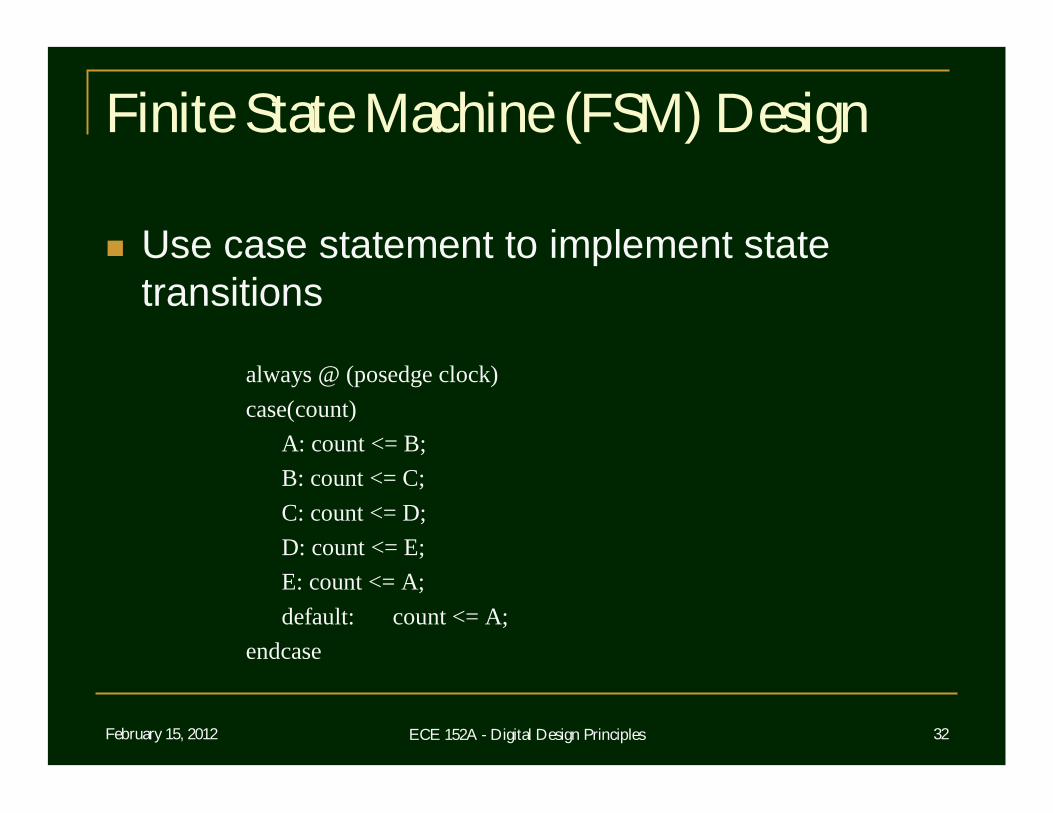
Use case statement to implement state transitions
always @ (posedge clock)case(count)
A: count <= B;B: count <= C;C: count <= D;D: count <= E;E: count <= A;default: count <= A;
endcase
February 15, 2012 ECE 152A - Digital Design Principles 33
Finite State Machine (FSM) Design
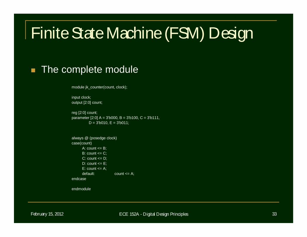
The complete modulemodule jk_counter(count, clock);
input clock;output [2:0] count;
reg [2:0] count;parameter [2:0] A = 3'b000, B = 3'b100, C = 3'b111,
D = 3'b010, E = 3'b011;
always @ (posedge clock)case(count)
A: count <= B;B: count <= C;C: count <= D;D: count <= E;E: count <= A;default: count <= A;
endcase
endmodule
February 15, 2012 ECE 152A - Digital Design Principles 34
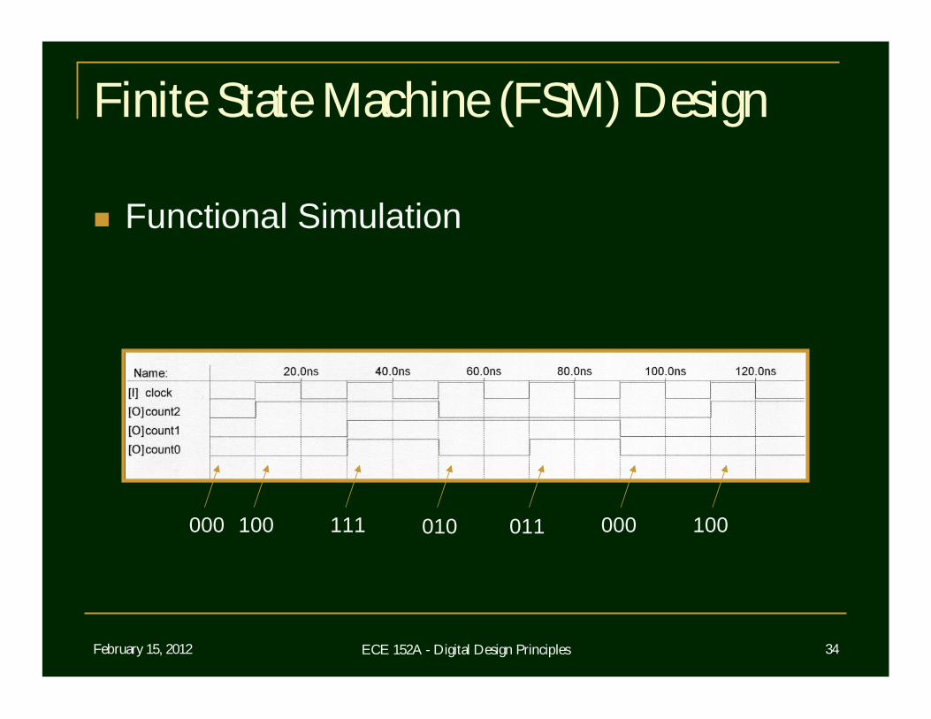
Finite State Machine (FSM) Design
Functional Simulation
000 100 111 010 011 000 100