leading partner in test & mechatronic simulation
TRANSCRIPT

1
Leading Partner in Test & Mechatronic Simulation
TEA Pipe Fully integrated solution inside Virtual.Lab Motion / Catia V5 LMS 3D division

copyright LMS International - 2013
2
Analyses of flexible parts with TEA Pipe Beam
Chapter 3
Pipe connections

copyright LMS International - 2013
copyright LMS International - 2013
1. Introduction
2. Collector
3. Separator
4. Assembly
Content
copyright LMS International - 2013
copyright LMS International - 2013
1. Introduction Several pipes/hoses can be connected with so called Collectors or Separators. The results will be a connection object (Assembly), which is an independent object. The following picture shows some use cases and the used terminology within TEA-PIPE.
Pipe connections

copyright LMS International - 2013
copyright LMS International - 2013
Terminology: Collector: external part as a connecting part. It’s made of connection points, which define the orientation points for the pipes/hoses to be mounted. "Inactive“ pipe connector : end of a pipe/hose, which is connected to a collector Separator : external part as a “distance keeper” of 2 parts. Separator Slot : cut out of a separator in which the pipe/hose will be hold. Separator Support : part of the pipe/hose, which will be snapped in the separator slot. Assembly : number of independent pipe/hoses, collectors and separators, which are used for a common simulation. Assembly Element : Element which is part of a an assembly (pipe/hose, collector, or separator).
Pipe connections
copyright LMS International - 2013
copyright LMS International - 2013
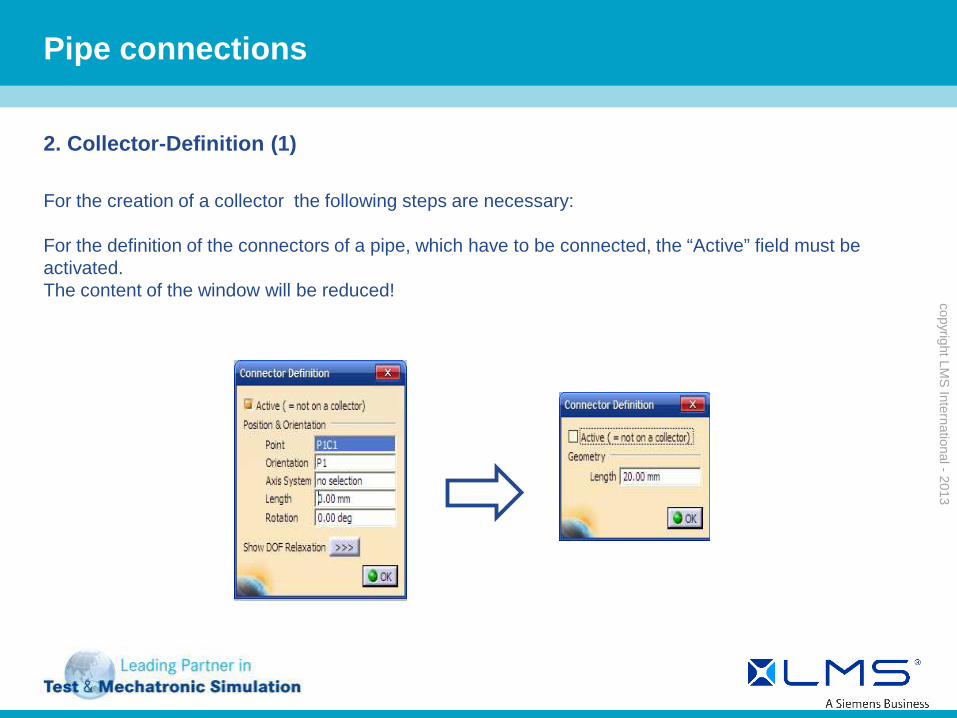
2. Collector-Definition (1) For the creation of a collector the following steps are necessary: For the definition of the connectors of a pipe, which have to be connected, the “Active” field must be activated. The content of the window will be reduced!
Pipe connections

copyright LMS International - 2013
copyright LMS International - 2013
2. Collector-Definition (2)
The function “Create Pipe collector” is available in the Wireframe And Surface Geometry or Part Design workbench. The “Create Pipe collector” icon will be used for creation of a new Pipe Collector in the actual part. The collector definition window is divided in several tab pages: · General : used to define geometrical and physical properties including nozzles ; · Kinematic : is used for the definition of kinematic or dynamic accelerations (only, when a collector is defined as fixed ).
Pipe connections

copyright LMS International - 2013
copyright LMS International - 2013
2. Collector-definition (3) First of all, choice of the part, which represents the collector. Accelerations will be defined as rigid body vectors. For example gravity is defined as (0 m_s2 ; 0 m_s2 ; -9.81 m_s2). The connectors themselves will be defined in Nozzles. To add one, click ‘+’ in the listing area, afterwards fill out all fields. To remove a Nozzle, just click on ‘-’ in the listing area. To edit a Nozzle just double click on it.
Pipe 1
Pipe 2
Pipe 3
Pipe connections

copyright LMS International - 2013
copyright LMS International - 2013
2. Collector-Definition (4) Additional nozzles can be connected to the collector (see picture below).
Pipe 1
Pipe 2
Pipe 3
Pipe connections
copyright LMS International - 2013
copyright LMS International - 2013
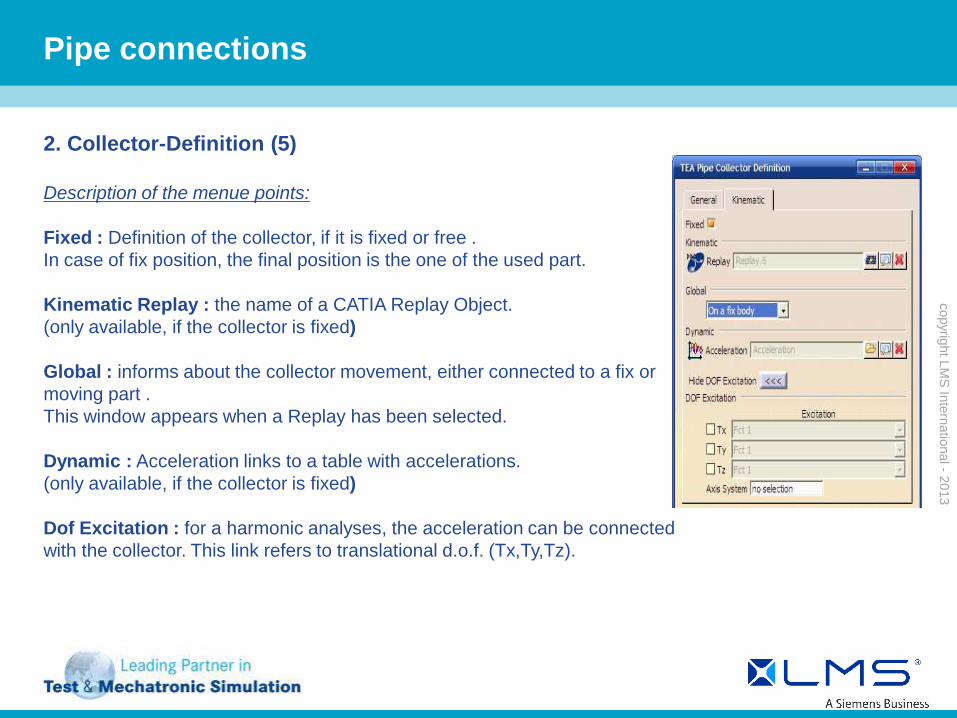
2. Collector-Definition (5) Description of the menue points: Fixed : Definition of the collector, if it is fixed or free . In case of fix position, the final position is the one of the used part. Kinematic Replay : the name of a CATIA Replay Object. (only available, if the collector is fixed) Global : informs about the collector movement, either connected to a fix or moving part . This window appears when a Replay has been selected. Dynamic : Acceleration links to a table with accelerations. (only available, if the collector is fixed) Dof Excitation : for a harmonic analyses, the acceleration can be connected with the collector. This link refers to translational d.o.f. (Tx,Ty,Tz).
Pipe connections

copyright LMS International - 2013
copyright LMS International - 2013
2. Collector Definition (6) Symbolic representation A symbolic representation will be shown in the 3D View. A yellow spline represents the pipe/hose and the collector will be shown as blue dotted lines from the collector center to each nozzle.
Pipe connections
copyright LMS International - 2013
copyright LMS International - 2013
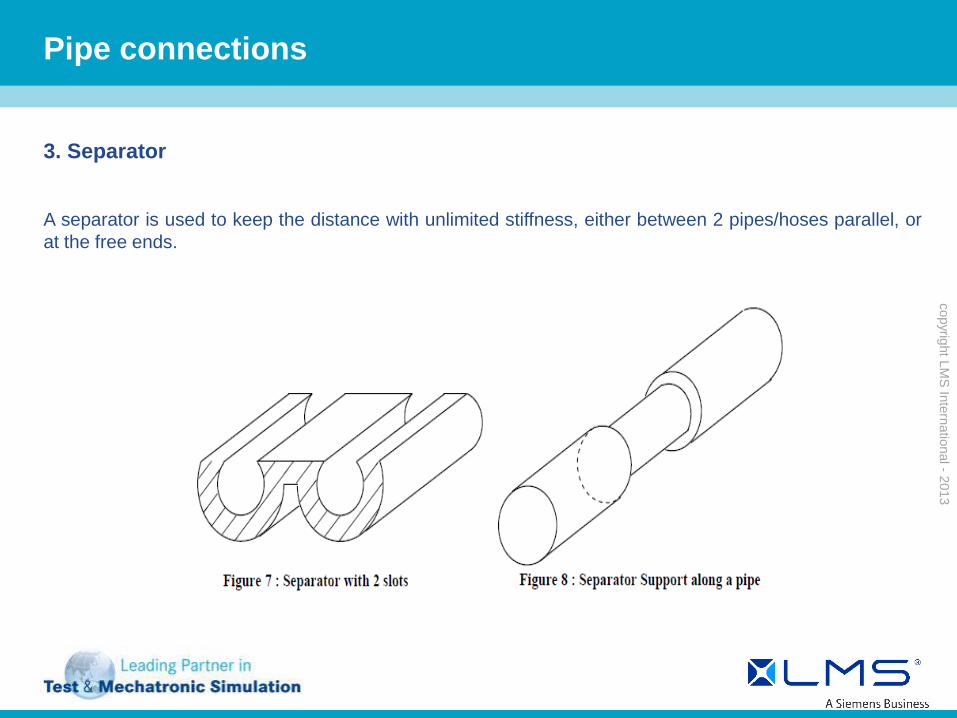
3. Separator
A separator is used to keep the distance with unlimited stiffness, either between 2 pipes/hoses parallel, or at the free ends.
Pipe connections
copyright LMS International - 2013
copyright LMS International - 2013
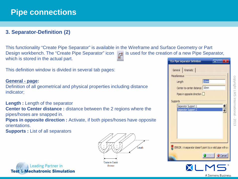
3. Separator-Definition (2)
This functionality “Create Pipe Separator” is available in the Wireframe and Surface Geometry or Part Design workbench. The “Create Pipe Separator” icon is used for the creation of a new Pipe Separator, which is stored in the actual part. This definition window is divided in several tab pages: General - page: Definition of all geometrical and physical properties including distance indicator; Length : Length of the separator Center to Center distance : distance between the 2 regions where the pipes/hoses are snapped in. Pipes in opposite direction : Activate, if both pipes/hoses have opposite orientations. Supports : List of all separators
Pipe connections

copyright LMS International - 2013
copyright LMS International - 2013
3. Separator-Definition (3) Kinematic - page: here the definition of all kinematic or dynamic accelerations can be made (if a collector is defined as fixed). Fixed: defines if a separator has a fix or free position Position Axis System : Definition of the axis system in end position and the orientation of a separator (if a separator is defined as fixed). DOF Relaxation : release of single components in translational or rotational frame (if a separator is defined as fixed) Kinematic Replay : Connection to a REPLAY object. Global informs about the movement of a separator, either connected to a fixed or moving part. This window section appears only when a replay was selected. Acceleration : refers to a table with accelerations. (if a collector is defined as fixed). Dof Excitation : used for a harmonic response analyses. The acceleration can be connected to the separator. This link refers to translational d.o.f. (Tx,Ty,Tz).
Pipe connections
copyright LMS International - 2013
copyright LMS International - 2013
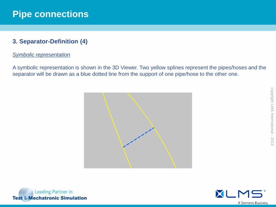
3. Separator-Definition (4) Symbolic representation A symbolic representation is shown in the 3D Viewer. Two yellow splines represent the pipes/hoses and the separator will be drawn as a blue dotted line from the support of one pipe/hose to the other one.
Pipe connections
copyright LMS International - 2013
copyright LMS International - 2013
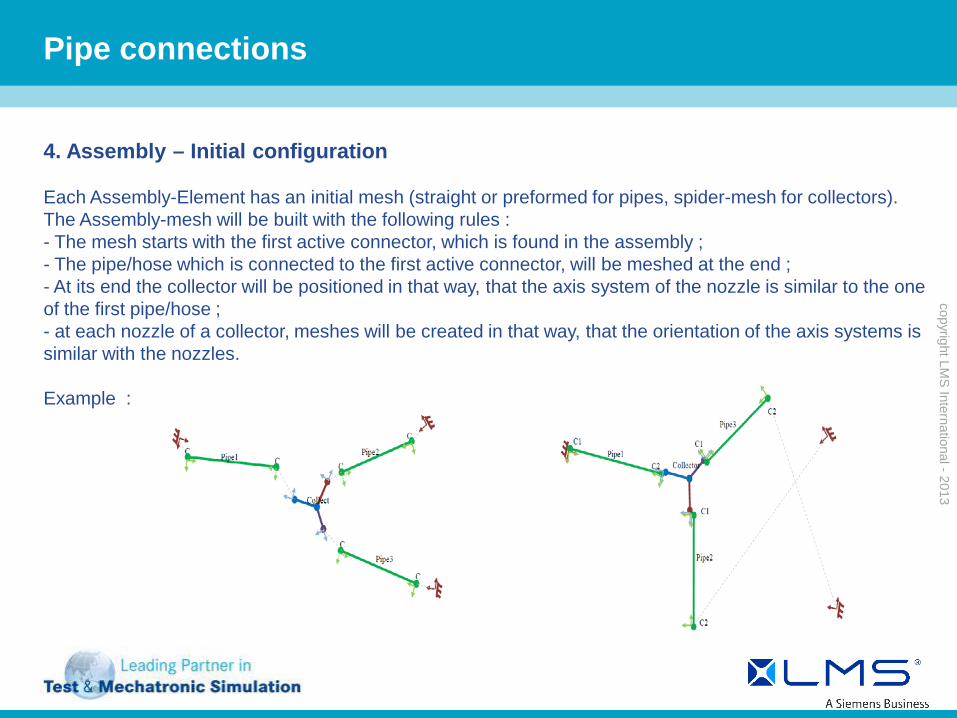
4. Assembly – Initial configuration Each Assembly-Element has an initial mesh (straight or preformed for pipes, spider-mesh for collectors). The Assembly-mesh will be built with the following rules : - The mesh starts with the first active connector, which is found in the assembly ; - The pipe/hose which is connected to the first active connector, will be meshed at the end ; - At its end the collector will be positioned in that way, that the axis system of the nozzle is similar to the one of the first pipe/hose ; - at each nozzle of a collector, meshes will be created in that way, that the orientation of the axis systems is similar with the nozzles. Example :
Pipe connections

copyright LMS International - 2013
copyright LMS International - 2013
4. Assembly – Simulation (1)
The simulation of an assembly is used in the same way as for a classical pipes/hoses with the TEA Pipe Application-Object. All assembly-elements will be listed in the window "Assembly“ . To have access, just double click on it. The assembly window contains 2 pages: -Assembly Description : List of all Assembly-Elements (double click to activate)
Pipe connections

copyright LMS International - 2013
copyright LMS International - 2013
4. Assembly – Simulation (2)
-History Definition : description of the history for the assembly.
Pipe connections