l d operators manuals manual/56402 29.0...• do not nm an engine with the air intake (suencer)...
TRANSCRIPT

-(f.RIJ .· .. · " . ~ . ., . _,.
"' "' () q
· .li L D 'II'
OPERATORS MANUAL .· MARINE DIESEL GENERATORS
29.0 EGED 60Hz 23.0 EGED 50 Hz Single and Three Phase .
PUBLICATION NO. 056402 REVISIONO
MARCH 2017
member' WESTERBEKE CORPORATION • MYLES STANDISH INDUSTRIAL PARK ~--- 150 JOHN HANCOCK ROAD, TAUNTON, MA 02780·7319 U.S.A. §.J!H TEL: (508)823·7677 • FAX: {508)884-9688 • WEBSITE: WWW. WESTERBEKE.COM

CALIFORNIA PROPOSITION 65 WARNING
Diesel engine exhaust and some of its constituents are known to the State of California to cause cancerJ birth defectsJ and other reproductive harm.
A wARNING: Exhaust gasses contain Carbon Monoxide, an odorless and colorless gas. Carbon Monoxide is poisonous and can cause unconsciousness and death. Symptoms of Carbon Monoxide exposure can include: • Dizziness •Nausea •Headache
• Throbbing in Temples • Muscular Twitching • Vomiting
• Weakness and Sleepiness •Inability to Think Coherently
IF YOU OR ANYONE ELSE EXPERIENCE ANY OF THESE SYMPTOMS, GET OUT INTO THE FRESH AIR IMMEDIATELY. If symptoms persist, seek medical attention. Shut down the unit and do not restart until it has been inspected and repaired.
This WARNING DECAL is provided by WESTERBEKE and should be fixed to a bulkhead near your engine or generator.
WESTERBEKE also recommends installing CARBON MONOXIDE DETECTORS in the living/sleeping quarters of your vessel. They are inexpensive and easily obtainable at your local marine store.

SAFETY INSTRUCTIONS IRTRODUCnON Read this safety 11Ullluol carefully. Most accidents are caused by failure to follow fundamental rules and precautions. Know when dangerous conditions exist and toke the necessary precautions to protect yourself, your personne4 and your machinery. The foUowing sofety instruciions are in compliance with the American Boat and Yacht Council (ABYC) standards.
PREVENT ELEcTRIC SHOCK
A WARNING: liD IIIII tout:h AC electrical t:llllllet:tiDifS while IIIJine/s runlling. Lethal raltage is ptt~Sent at tllese t:D111181:ti1111SI
• Do not oPerate tbis machinery without electrical enclosures and co:vers in place.
• Shut off electrical power before accessing electrical equipment ·
• Use insulated mats whenever working on electrical equipment
• Make sure your clothing and skin are dty, not damp (particularly shoes) when handling electrical'equipment.
• Remove wristwatch and all jewelry when working on electrical equipment
PREVENT BURRS- HOT ENGINE
A WARNING: Do 11111 fDIIDb bill tlllg/ne patls or 8Xhstlst"""" comptlllllllls. A IIIIJIIIng engine gets ,.
' • Monitor EingiQe -~ cooiant ievei at the plastic
coolant recovery·tank and periodiCaly at the filler atp location on the water jacketed exhau.<tt manifold, but only when the engine is COLD.
j AwA1818: ___ ,.,.,_
• In case of an engine overheat, allow the engine to cool before touching the engine or checking the coolant.
PREVENT BURNS- FIRE
I A WARIIIIIG: Flnl""" ...... illjmp ... _, ]
• Prevent flash fires. Do not smoke or permit flames or sparlcs to occur near the fuel injector, fuel line, filter, fuel pump, or other potential sources of spilled fuel or fuel vapors. Use a suitable container to catch all fuel when removing the fuel lines or fuel filters.
• Do not operate with the air cleaner/silencer removed. Backfire can cause severe injury or death.
• Do not smoke or permit flames or sparks to occur near the fuel system. J(eep ~compartment and the engine 'clean imd free of debris to minimize the chances of fire. wq,e up all spilled fuel and engine oil.
• Be aware- diesel fuel will bum.
PREVENT BURNS- EXPLOSION
A WARNING: Exp/llsiiiiiS frllm fuel V11J1D1S can t:aiiSI1
Injury D1 dlllf#'l
• . Follow re--fueling safety instructions. Keep the vessel's hatches closed when fueling. Open and ventilate the cabin after fueling. Check below for fumes/vapor refore running the blower. Run the blower per four minutes before starting your engine.
• All fuel vapors are highly explosive. Use extreme care . when handling and storing fuels. Store fuel in a well-ventilated area away from spark-producing equipment and out of the ~h of children.
• Do not fill the fuel tank(s) while the ,engine while it is running. • Shut off the fuel service Valve at the engine when servicing
the fuel system. Take care in catching any fuel that might spill. DO NOT allow any smoking, open flames, or other . sources of fire near the fuel system or engine when servicing. Ensure proper ventilation exists when servicing the fuel system.
• Qo not alter or modify the fuel system. · • ~~ sure all fuel supplies have a positive shutoff valve. • Be certain fuel line fittings are ?dequately tightened and
free of leaks. • Make sure a fire extinguisher is installed nearby and is
properly maintained. Be familiar with its proper use. Extinguishers rated ABC by the NFPA are appropriate for all applications encountered in this environment.
Engines & Generators
i

SAFETY INSTRUCTIONS ACCIDENTAL STARTING
A WARNING: Accidental starting can cause injury or death!
• Disconnect the battery cables before servicing the engine/ generator. Remove the negative lead first and reconnect it last.
• Make certain all personnel are clear of the engine before starting.
• Make certain all covers, guards, and hatches are reinstalled before starting the engine.
BAmRY EXPLOSION
A WARNING: Battery explosion can cause injury or death!
• Do not smoke or allow an open flame near the battery being serviced. Lead acid batteries emit hydrogen, a highly explosive gas, which can be ignited by electrical arcing or by lit tobacco products. Shut off all electrical equipment in the vicinity to prevent electrical arcing during servicing.
• Never connect the negative(-) battery cable to the positive ( +) connection terminal of the starter solenoid. Do not test the battery condition by shorting the terminals together. Sparks could ignite battery gases or fuel vapors. Ventilate any compartment containing batteries to prevent accumulation of explosive gases. To avoid sparks, do not disturb the battery charger connections while the battery is being charged.
• Avoid contacting the terminals with tools, etc., to prevent bums or sparks that could cause an explosion. Remove wristwatch, rings, and any other jewelry before handling the battery.
• Always tum the battery charger off before disconnecting _ the battery connections. Remove the negative lead first and reconnect it last when disconnecting the battery.
BAnERYACID
A WARNING: Sulfuric acid in batteries can cause severe injury or death!
• When servicing the battery or checking the electrolyte level, wear rubber gloves, a rubber apron, and eye protection. Batteries contain sulfuric acid which is destructive. If it comes in contact with your skin, wash it off at once with water. Acid may splash on the skin or into the eyes inadvertently when removing electrolyte caps.
TOXIC EXHAUST GASES
A WARNING: Carbon monoxide (CO} is a deadly gas!
• Ensure that the exhaust system is adequate to expel gases discharged from the engine. Check the exhaust system regularly for leaks and make sure the exhaust manifolds are securely attached and no warping exists. Pay close attention to the manifold, water injection elbow, and exhaust pipe nipple.
• Be sure the unit and its surroundings are well ventilated. • In addition to routine inspection of the exhaust system,
install a carbon monoxide detector. Consult your boat builder or dealer for installation of approved detectors.
• For additional information refer to ABYC T-22 (educational information on Carbon Monoxide).
A WARNING: Carbon monoxide (CO) is an invisible odorless gas. Inhalation produces flu-like symptoms, nausea or death!
• Do not use copper tubing in diesel exhaust systems. Diesel fumes can rapidly destroy copper tubing in exhaust systems. Exhaust sulfur causes rapid deterioration of copper tubing resulting in exhaust/water leakage.
• Do not install exhaust outlet where exhaust can be drawn through portholes, vents, or air conditioners. If the engine exhaust discharge outlet is near the waterline, water could enter the exhaust discharge outlet and close or restrict the flow of exhaust. Avoid overloading the craft.
• Although diesel engine exhaust gases are not as toxic as exhaust fumes from gasoline engines, carbon monoxide gas is present in diesel exhaust fumes. Some of the symptoms or signs of carbon monoxide inhalation or poisoning are: Vomiting Dizziness Throbbing in temples Muscular twitching Intense headache Weakness and sleepiness
AVOID MOVING PARTS
A WARNING: Rotating parts can cause injury or death!
• Do not service the engine while it is running. If a situation arises in which it is absolutely necessary to m'ake operating adjustments, use extreme care to avoid touching moving parts and hot exhaust system components.
Engines & Generators
ii
SAFETY INSTRUCTIONS a Do not wear loose clothing or jewehy when servicing
equipment: avoid wearing loose jackets, shirts, sleeves, rings, necklaces or bmcelets that could be caught in
. maving parts. • Make sure all attaching hardware is properly tightened.
Keep protective shields and guards in their respective places at all times. · ·
a Do not check fluid levels or the drive belt's tension while . the engine is operating.
IIi Stay clear of the drive shaft and the transmission coupling when the engine is running; h3ir and clothing can easily be caught in these rotating parts.
HAZARDOUS NOISE
A WARNING: High llt1ise IBvetsl:atl t:BIISfl bearing IIISSI
~ Never operate an engine without its -muffler installed. • Do not nm an engine with the air intake (sUencer)
removed.
A WARNING: Dollllf Pllltk Dll macblnety PJbell,. are . mBIItally D1 physlally /muipat;llatstJ by fatl!lllel
OPERATORS MANUAL ·Many of the preceding safety tips and warnings ate-repeated in yOur opemtors Manual along with other cautions and notes to highlight critical inforination. Read your manual carefully, m•tain your equipment. and follow all safety procedures. .
ENGINE AID GENERATOR INSTALLATIONS . Preparations to install an engine should begin with a thorough examiDation of the American Boat and Yacht Council's (ABYQ standat:ds. These standards ate a combination of soun:es including the USCG and the NPPA. Sections of the ABYC standards of particular interest are:
H-32 Ventilation for boats using diesel fuel H-33 Diesel Fuel Systems P-1 Installatiion of Exhaust Systems for Propulsion
and Auxiliary Engines P-4 Marine Jnbo$'d Engines and Transmissions E-ll AC & DC Electrical Systems on Boats TA Batteries and Battery Chargers
All installations must comply with the Federal Code of Regulations (FCR.).
ABYC, NFPA AND USCG PUBUCAnONS FOR .. INSTALLING MARINE ENGINES AND GENERATORS
Read the following ABYC, NFPA and USCG publications for safety codes and standards. Follow their recommendations when insialUng your UNIVERSAL engine ABYC (American Boat and Yacht Council) "Safety Standaras for Small Craft'' .
Order From: ABYC 613 Third Dtreet, Suite 10 Annapolis, MD 21403 (410) 990-4460
· www.abycinc.O!J NFPA (National Fire Protection Association) "Fue Protection Standard for Motor Craft" Order From~ NFPA 1 Ba.tterymarch Park P.O. Box 9101 Quincy, MA 02269--9101 USCG (United States Coast Guard) "CFR 33 AND CFR46'• Code.ofFedeml Regulations Order From: U.S. Government Printing Office Washington, D.C. 20404
I""''V"IWESTERSEKB (Engines & Generators
••• Ill

.INSTALLATION
When installing WESTERBEKE engines and generators it is important that strict attention be paid to the following information:
CODES AND REGULATIONS Strict federal regulations, ABYC guidelines, and safety codes must be complied with when installing engines and generators in a marine environment.
SIPHON-BREAK For installations where the exhaust manifold/water injected exhaust elbow is close to or will be below the vessel's waterline, provisions must be made to install a siphonbreak in the raw water supply hose to the exhaust elbow. This hose must be looped a minimum of 2ft' above the vessel's waterline. Failure to use a siphon-break' when the exhaust manifold injection porl Ia at or below the loaJ1 waterline will result in raw water damage to Ow engine and po~Bible Jlboding of the boat. If you have any doubt abOut' the positii;>.n of t}w. water-injected exhaust elbow relative : to· the vessel's watedirte.under the vessel's various operating cOnditions, install a siphon-break. .. ,. .. . . .....
AVAILABLE FROM YOUR. WESTERBEKE
NOTE: A si.Phon~break requires periodic inspection ·and cleaning to ensure proper operation. Failure to properly maintain a siphon-break can· result in catastrophic en~ne damage. CoMllt the siphon-break manufacturer for proper maintenance.
. DEALER
EXHAUST SYSTEM · Tlie exhauSt system's hose 'Mli~t:~ certified for marine use. Corrugated Marine Exhaust Hose is recommen~~ The use of this type of hose; a,llows for extreme bends and turns without the~ of additiinal fitting and clamps to accomplish these bends and turns .In this regard, a single length of coxrugated 9xhaust hose can be used. 'The system MUST be designed to prevent the entry of water·into the exhaust syste~ · under any sea conditions and at any angle of vessels heal.
A detailed Marine lnstaHation Manual covering gasoline and diesel engines an~ generators is supplied wHb ~ unit sold. This manual Js also available In pdf format on our website to download We~lte: www.westerbeke.com
l"YYV'IWESTERBEKE l Eng/,_ & Generators
iv
SIPHON-BREAK WfTH fifAINLES, LOOP FOR 1" HOSE . PART NO. 044010

TABLE OF CONTENTS
Parts Identification ............................................. 2 Glow Plugs ......................................................... 21 Introduction ......................................................... 3 Inspection and Testing ................................. 21 Fuel, Engine Oil and Engine Coolant.. ................ 5 Alternators ......................................................... 22 Preparations for Initial Start·Up ......................... 6 Testing and Troubleshooting ....................... 22 Control Panel ....................................................... 7 Battery Care ................................................. 24
Manual Engine Shut-Off ............................... 7 Starter Motor ..................................................... 25 Starting/Stopping Procedure ............................... 8
Remote Panels ............................................... 8 . Testing with Electrical Jumper .................... 25 Testing with Screwdriver ............................. 26
Benerator Break-In Procedure ... : ........................ 9 Removing for Service .................................. 27 Daily Routine ....................................................... 9 Raw Water Pump (Exploded View) .................... 28 Maintenance Schedule ..................................... 1 o Fuel System ........................................... : ........... 12 Cooling System .................................................. t3',,
Raw Water Intake ........................................ 13 Draining the Raw Water System ................. 13 Fresh Water Cooling Circuit ......................... 14 Changing the Coolant. ................................. 14 Thermostat ................................................... 15 Raw Water Cooling Circuit ......................... 16 Heat Exchanger ........................................... 16 Raw Water Pump ......................................... 16
Engine Lubricating Oil ....................................... 17 Engine Oil Change ...................................... 17
Water Heater Installation (Optional) ................. 29 Remote 011 Filter (Optional) .............................. 30 Block Heater (Optional) .................................... .30 Specifications .................................................... 31 Benerator Information ...................................... .33 Twelve Lead Winding Connections .................. .34 Electronic Regulation (AVR) ............................. 35 Internal Wiring Diagram .................................... 37 AC Outlet Configuration ..................................... 37 Shore Power Transfer Switch ........................... .38 Lay·Up and Recommissioning.' .......................... 39 Suggested Spares ............................................. .41
Engine Troubleshooting ..................................... 18 Wiring Diagrams and Schematics .................... .42 Engine AdJustments ........................................... 19
Drive Belt Adjustment ................................. 19 Fuel Injectors ............................................... 19 Troubleshooting Instrument Gauges ........... 19 Testing Oil Pressure ..................................... 20 Checking Valve Clearance ........................... 20 Valve Adjustment. ........................................ 20
r.viWE§I"ERBEKE l Engines & Generators
1

PARTS IDENTIFICATION
CONNECTION FOR SIPHON BREAK
REAR
FUEL LIFT
MANIFOLD PRESSURE CAP COOLA~T FILL
DRIVE BELT COVER
DC ALTERNATO
FRONT.
FLEXIBLE ISOLATED MOUNTS
COOLANT FILL
RIGHT SIDE
CONTROl
LEFT. SIDE
Engines & Generators
2
OIL FILL I
PUMP
DC FIELD BREAKER
SYPHON BREAK CONNECTION
INTRODUCTION This WESTERBEKE Diesel Generator is a product of WESTERBEKE's long years of experience and advanced . technology. We take great pride in the superior durability and dependable performance of our engines and generators. Thank you for selecting WESTERBEKE. In order to get the full use and benefit from your generator it is important that you operate and maintain it correctly~ This manual is designed to help you do this. Please, read this manual carefully and observe all the safety precautions throughout Should your generator require servicing, contact your nearest WESTERBEKE dealer for assistance. This is your operators manual. Along wi~ ~ manual, .there is an Installation Manual and Parts Information. A Semce Manual is available in pdf form on our website or can be ordered in book form from a WESTERBEKFJUNIVERSAL Dealer
WARRANTY PROCEDURES Your WESTERBEKE Warranty Statement is included in the product documentation package. There is a Warranty Registration Card you can fill out and mail to Westerbeke · Corporation or go to our website:www. westerbeke.com and register your products warranty on line. You should receive a Customer Identification card in the mail within 60 days of registering. If.you do not, please contact the factory and have your product model number, serial number and in service · date available.
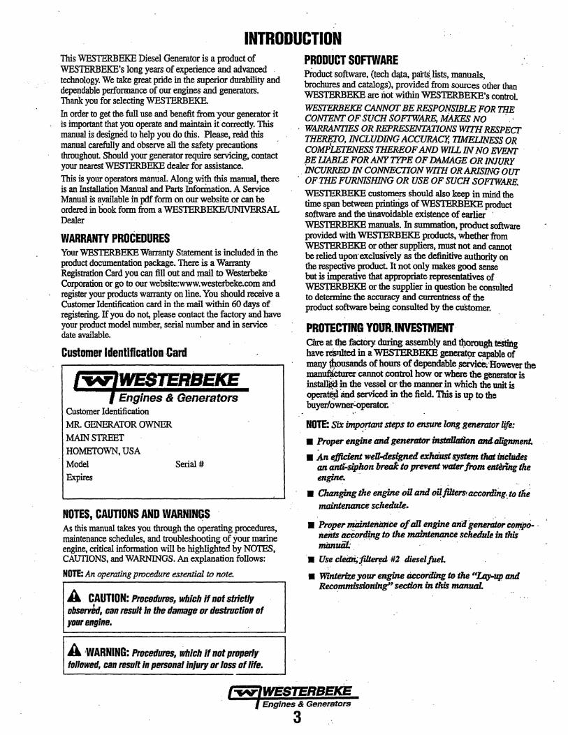
Customer Identification Card
I,.,IWESTERSEKE I Engines & Generators
Customer Identification MR. GENERATOR OWNER MAIN STREET HOMETOWN, USA Model Expires
Serihl #
NOTES, CAUTIONS AND WARNINGS As this manual takes you through the operating procedures, maintenance schedules, and troubleshooting of your marine engine, critical information will be highlighted by NOTES, CAUTIONS, and WARNINGS. An explanation follows:
NOTE: An operating procedure essential to note.
A CAUTION: Proceduress which if not strictly observed, can result In the damage or destruction of your engine.
A ·WARNING: Procedures, which If not properly followed, can result in personal injury or loss of life.
PRODUCT SOFTWARE Pioduct software, (tech dlUa. pans, lists, manuals, brochures and catalogs), provided from sources other than WESTERBEKE are not within WESTERBEKE's control. WESTERBEKE CANNOT BE RESPONSIBLE FOR THE CONTENT OF SUCH SOFTWARE, MAKEs NO . WARRANTIES OR REPRESENTATIONS WITH RESPECT THERETO, INCLUDING ACCURACY; TIMELINESS OR COMP'zErENESS THEREOF AND W1U IN NO EVENT · BE UABLE FOR ANY TYPE OF DAMAGE OR INJURY iNCURRED IN CONNECI10N WITH OR ARISING OUT
.. OF THE FURNISHING OR USE OF SUCH SOF1WARE. WESTERBEKE customers should also keep in mind the time span between printirigs ofWESTERBEKE product software and the tinavoidable existence of earlier · WESTERBEKE manuals. In summation, product software provided with WESTERBEKE products, whether from WESTERBEKE or other suppliers, must not and cannot be relied upon· exclusively as the definitive authority on the respective product It not only makes good sense but is imperative that appropriate representatives of WES'IERBEKE or the supplier in question be consnited to detennine the accuracy and currentness of the product software being consulted by the customer.
PROTECTING YOUR. INVESTMENT· care at~ factory during assembly and tl)orough testing have n$tdted in a WESTERBEKE generat9r capable of Ill8I).Y tbousands of hours of dependable ~ce~ ·However the manuflicturer cannot control how or where the generator is install~ in the vessel or the manner in which the unit is operat6jl 'and serviced in the field. This is up to the buyer/owner.:Operator. ·
;•
NOTE: SU: imp~rtant steps to ensure long generaJor life:
• Proper engine and generotor insttlllaiion and.alignment.
• An efficient weU-designed exhtiust system that irtt;,.ludes an mzti:.siphon breafc to prevent water from entering the engine.
. . . . • Changing the engine oil and oil filters' accordiit.g .. to tlie
maintenance scltedule.
• .Proper niainte1tizliee of all engine a7ii1 generfdor compo- · ne1its accortli;ng to the maintenance schedule in this mimuii! . .
·• Use clei:bi;:(ilierf!d #2 diesel fUel.
• Wznterize your engine ticcoriliitg to the ""Lay-up and Reco;mmissioninlf' section in this manuaL
Engines & Generators
3

INTRODUCTION SERIAL NUMBER LOCATION The engine's model and serial number are lo,cate<i on a nameplate mounted on the side of the water jacketed exhaust manifold. The engine's serial number is also found stamped in the engine block on a flat surface just above the the side oil fill opening. Take time to enter this information below on the illustrated nameplate.
50 HZ. 60HZ.
I
An identification plate on the top of the engine air intake also displays the engine model and serial number.
CARBON MONOXIDE DETECTOR WESTERBEKE recommends mounting a carbon monoxide detector in the vessels living quarters. Carbon monoxide, even in small amounts, is deadly. The presence of carbon monoxide indicates an exhaust leak from the engine or generator or from the exhaust elbow/exhaust hose, or the fumes from a nearby vessel are entering your boat. If carbon monoxide is present, ventilate the area with clean air and correct the problem immediately!
NOTE: A carbon monoxide warning decal has been provided by WESTERBEKE. Affix this decal in a visible position in the engine room.
UNDERSTANDING THE DIESEL ENGINE The diesel engine closely resembles the gasoline engine, since the mechanism is essentially the same. The cylinders are arranged above a closed crankcase; the crankshaft is of the same general type as that of a gasoline engine; and the diesel engine has the same types of valves, camshaft, pistons, connecting rods and lubricating system. Therefore, to a great extent, a diesel engine requires the same preventive maintenance as a gasoline engine. The most important factors are proper ventilation and proper maintenance of the fuel, lubricating and cooling systems. Replacement of fuel and lubricating filter elements at the time periods specified is a must, and frequent checking for contaillination (that is, water, sediment, etc.) in the fuel system is also essential. Another important factor is the use of the same brand of high detergent diesel lubrication oil designed specifically for diesel engines. The diesel engine does differ from the gasoline engine, however, in its method of handling and firing of fuel. The carburetor and ignition systems are done away with and in their place is a single component - the fuel injection pump -which performs the function of both.
ORDERING PARTS Whenever replacement/service parts are needed, always provide the generator model number, engine serial number, and generator serial number as they appear on the silver and black name plate located on the generator end. You must provide us with this information so we may properly identify your generator set. In addition, include a complete part description and part number for each part needed (see the separately furnished Parts List). Also insist upon WESTERBEKE packaged parts because will fit or generic parts are frequently not made to the same specifications as original equipment.
SPARES AND ACCESSORIES Certain spares will be needed to support and maintain your WESTERBEKE generator. Your local WESTERBEKE dealer will assist you in preparing an inventory of spare parts. See the SPARE PARTS page in this manual. For Engine and Generator Acces8ories, see the ACCESSORIES brochure.
INSTALLATION MANUAL The Westerbeke Installation Manual publication #043268 is supplied with this unit.
Engines & Generators
4
DIESEL FUEL, ENGINE OIL AND ENGINE COOLANT
DIESEL FUEL Use a diesel fuel that meets the requirements of No. 2-D SAE J 313 and has a Cetane rating of #45 or higher grade of diesel fuel according to ASTM 0975
Care Of The Fuel Supply Use only clean diesel fuel! The clearance of the components in your engines fuel injection pump is very critical; invisible dirt particles which might pass through the primary and secondary filters can damage these finely machined parts. It is impm1ant to buy clean fuel, and keep it dean. The best fuel can be rendered unsatisfactory by careless handling or improper storage facilities. To ensure that the fuel going into the tank for your engine's daily use is clean and pure, the f-ollowing practice is advisable: Pin-chase a well-known brand of fuel. The use of additives to combat BAC1ERIAL growth in the fuel tank is recommended such as Bio-Bor and an additive such as Diesel Kleen + Cetane Boost. to help restore lubricity back into the diesel fuel when an Ultra Low Sulfur diesel is being used. Install and regularly service a good, visual-type fuel filter/water separator between the fuel tank and the engine. The Raycor 500 MA or 230 RMAM are good examples of such filters. A 10 micron filter element is recommended.
ENGINE OIL Use a heavy duty diesel oil with an API classification ofCF, CG-4, CH-4 or CI-4. Change the engine oil and filter after an initial 50 hours of break-in operation. Then follow the oil and filter change intervals as specified in the MAINTENANCE SCHEDULE in this manual. Westerbeke Corporation does not approve or disapprove the use of synthetic oils. If synthetic oils are used, engine break-in must be performed using conventional oil. Oil change intervals must be as listed in the MAINTENANCE SCHEDULE section of this manual and not be extended if synthetic oils are used.
· NOTE: The infonnation above supersedes all previous statements regarding synthetic oil.
SAE OIL VISCOSITY .. For all temperature ranges: SAE 15W-40 or SAE lOW-40 ...
· ENGINE COOLANT WESTERBEKE recommends a mixture of 50% antifreeze and 50% distilled water. Distilled water is free from the chemicals that can corrode internal engine surfaces. The antifreeze performs double duty. It allows the engine to run at proper temperatures by transferring heat away from the engine to the coolant, and lubricates and protects the cooling circuit from rust and corrosion. Look for a good quality antifreeze that contains Supplemental Cooling Additives (SCAs) that keep the antifreeze chemically balanced, crucial to long term protection. The distilled water and antifreeze should be premixed before being poured into the cooling circuit.
NOTE: Look for the new environmentally-friendly long lasting antifreezethat'is now available.
. PURCHASING ANTIFREEZE Select a brand of antifreeze specified for diesel engines. Antifreeze specified for diesel engines contains a special additive to protect against cavitation erosion of the engine's cylinder walls. Prestone and Zerex are two nationally known brands that offer antifreeze specifically for use in diesel engines. Select the pre-mixed variety so that the correct mixture will always be added to the cooling system when needed. Change the antifreeze mixture according to the MA1NTENANCE SCHEJ?ULE in this manual.
MAINTEN.A8CE . Change the eniirte coolant every five years regardless ~f the number of operating hours as the chemical additives that protect and lubricate the engine have a limited ll.fe.
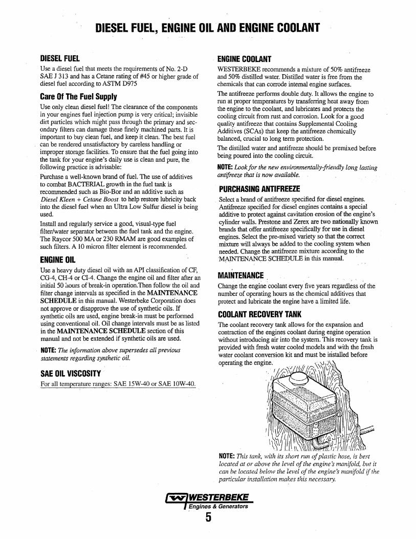
COOLANT RECOVERY TANK The coolant recovery tank allows for the expansion and contraction of the engines coolant during engine operation without iJ;ttroducing air into the system. This recovery tank is provided with fresh water cooled models and with the fresh water coolant conversion kit and must be installed before operating the engine.
. . f
. I
NOTE: This tank, ;vith its short run of plastic hose, is best located at or above the level of the engines tnanifold, but it can be located below the level of the engines manifold if the particular installation maJ:es this necessary.
Engines & Generators .. 5
PREPARATIONS FOR INITIAL START-UP
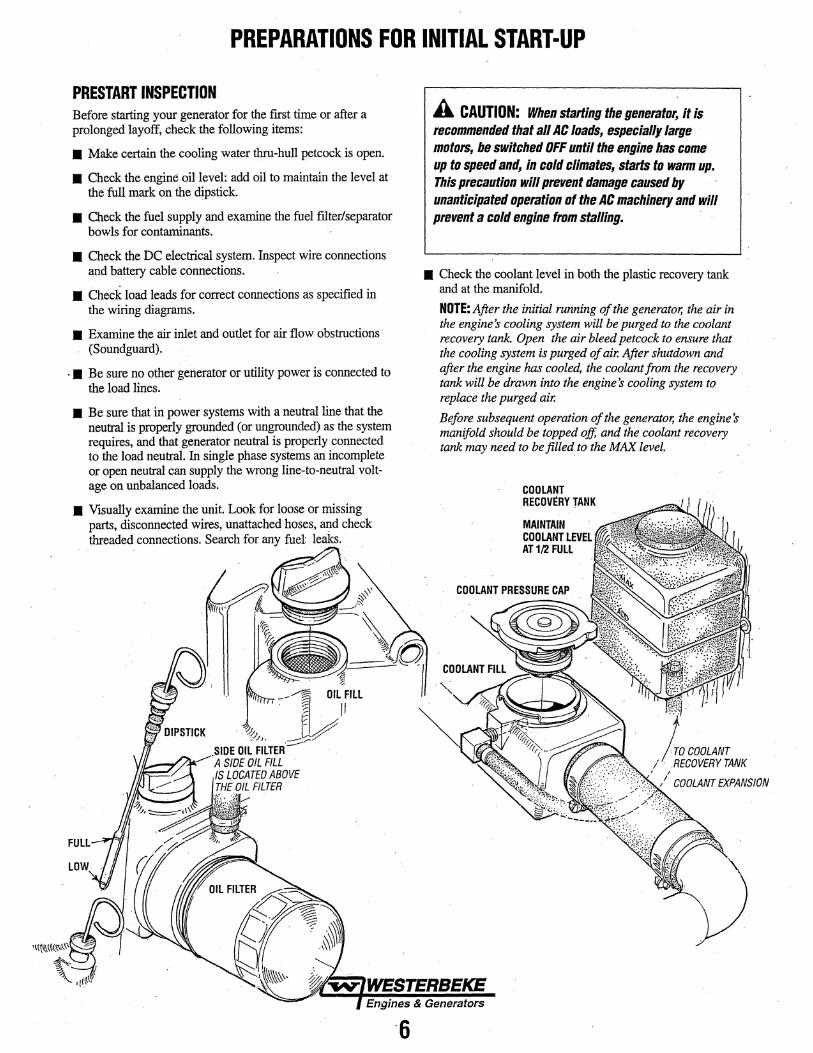
PRESTART INSPECTION Before starting your generator for the first time or after a prolonged layoff, check the following items:
• Make certain the cooling water thru-hull petcock is open.
• Check the engine oil level: add oil to maintain the level at the full mark on the dipstick.
• Check the fuel supply and examine the fuel fiiter/separator bowls for contaminants.
• Check the DC electrical system. Inspect wire connections and battery cable connections.
• Check load leads for correct connections as specified in the wiring diagrams.
• Examine the air inlet and outlet for air flow obstructions (Soundguard).
. • Be sure no other generator or utility power is connected to the load lines.
• Be sure that in power systems with a neutral line that the neutral is properly grounded (or ungrounded) as the system requires, and that generator neutral is properly connected to the load neutral. In single phase systems an incomplete or open neutral can supply the wrong line-to-neutral voltage on unbalanced loads.
• Visually examine the unit. Look for loose or missing parts, disconnected wires, unattached hoses, and check threaded connections. Search for any fuel' leaks.
A CAUTION: When starting the generator, it is recommended that all AC loads, especially large motors, be switched OFF until the engine has come up to speed and, in cold climates, starts to warm up. This precaution will prevent damage caused by unanticipated operation of the AC machinery and will prevent a cold engine from stalling.
• Check the coolant level in both the plastic recovery tank and at the manifold.
NOTE: After the initial running of the generator, the air in the engine's cooling system will be purged to the coolant recovery tank. Open the air bleed petcock to ensure that the cooling system is purged of air. After shutdown and after the engine has cooled, the coolant from the recovery . tank will be drawn into the engine 's cooling system to replace the purged air.
Before subsequent operation of the generator, the engine's manifold should be topped off, and the coolant recovery tank may need to be filled to the MAX level.
COOLANT RECOVERY TANK
MAINTAIN COOLANT LEVEL AT 1/2 FULL

GENERATOR INSTRUMENT CONTROL PANELS DESCRIPTION AND OPERATING INSTRUCTIONS
DESCRIPTION The Generators Instrument Control contains a compact gauge package, contrQl r9Cker switches, circuit fuses, check engine light, emergency stop toggle switch and a recording · hourmeter. These comJ>9nents are descdbed below. The 8 pin connector that is on the side of the Control Box is used to connect an optional remote Start/Stop panel or a second Control Panel. When an optional panel is connected, the 8 pin connector with jumper should be kept for future needs when · troubleshoolin$· Secure it to the lifting eye.
OR alATION STARTING/STOPPING INSTRUCTIONS
--· -START: The START rocker switch, when depressed. activates the starter motor. The starter M terminal then supplies DC power ·to the pull coil of the fuel solenoid .allowing fuel delivery to the injectors.
NOTE: It is important to closely monitor the panel gauges, Become aware of the normal engine readings and take immediate action if these readings start to vary.
---·--------~- .. -.
*STOP: The STOP rocker switch when pressed and held, ··opens the DC circuit supplying power to the·K2 Run Relay. De-acti.vati.ng it and shutting down ,th• engine drive.
THIS PANEL CANA~SO BE ., REMOTFLYUJCATED; REFER. TO THE FOLLOWING.PAGE
EMERGENCY STOP· 20A DC BREAKER
Fuse/DC Breaker: The control box has a 7.5 amp automotive type fuse to protect the-run circuit and remote panel: :A 20 amp DC breaker is on the control box protecting the unit's DC circuits and acts as an Emergency Stop Switch.
20A DC Breaker/Emergency Stop Switcb : This rocker switch on the front of the panel is Nonnally oH When depressed, it will open the DC circuit to the Control Box and shut the engine down. When servicing. this switch can be used as a breaker to prevent an accidental start.
Remote Panel Plug-In: A plug on the side on the 90ntrol box will allow for the mount:in~ of the remote instrument panel or the remote panel start/stop.
Coolalt Temperature: Engine coolant (water) temperature should normally indicate: 175° to.195°F (80° to 90°C).
*:MANUAL ENGINE SHUT·OFF
Engine Oil Pressure: Oil Pressure (psi) may fluctuate · depending on the generator load but should range between
• 35 to 55 psi. ·
DC Volts: Indicates the amount the battery is being charged and show 13V to 14V.
Hourmeter: Registers elapsed time and is used as a guide for when to perfonn scheduled maintenance.
Prebeat: The. PREHEAT rocker switch serves two purposes:
1. It activates th~ preheat circuit. 2. lt activates the .. K2 Run Relay. This supplies DC power to the Instrument.pahel.and Hour MeterDC power to the fuel pump. the Hold cOilm the fuel sol6!loid and the R terminal on the DC alternator.· .·
Should the engine fail: to stop when the fuel shut off solenoid is de~energised when the STOP button is depressed. The engine is equiped with a manual shut-off lever. This is located just below the fixed throttle le.ver on the side of the engine block below the fuel injection pmnp/Move this l~ver to the left and hold it there until the engine comes to a stop. Then release.
1-w"IWESTERB§KE ) EngineS & Generators 7 ... -

OPTIONAL REMOTE CONTROL PANELS OPERATING INSTRUCTIONS
DESCRIPTION There are several options available when selecting remote operation of your generator. 1. Mo'unt a second (repeating) Instrument Control Panel in a
remote location.
2. Simply remove the Instrument Control Panel from the control box and mount it as a remote panel.
NOTE: The Instrument Control Panel can be replaced by installing a basic start/stop panel in the control box.
3. Mount a remote start/stop control panel ina remote location.
The remote )?anels connect to the 15 pin plug on the back of the control box using the extension harnesses listed below.
EXTENSION HARNESS PN#056236 EG DIESEL (8 PIN) 15FT PN#056235 EG DIESEL (8 PIN) 30FT
REMOTE START/STOP PANEL· DESCRIPTION The Remote Start/Stop Panel has the same three rocker switches as the Instrument Control Panel. Their function is the same. This panel has a RELEASE STARTER LED. This LED will illuminate when the PREHEAT is depressed. When this panel is remote mounted, this LED will indicate when the generator has started. When depressing the START rocker switch, this LED will dim. When the generator starts, the LED will brighten. This indicates to release the START rocker switch. The PREHEAT rocker switch is held depressed for about 4-5 seconds to allow the oil pressure to reach 10 psi, then release it. For the REMOTE START/STOP PANEL wiring diagram and wiring harness, refer to the Table of Contents.
INSTRUMENT CONTROL PANEL(AS A REMOTE PANEL) PN56246
REMOTE START/STOP PANEL PN56320
Engines & Generators
8

GENERATOR BREAK-IN PROCEDURE DESCRIPTION Although your engine has experienced a minimum of one hour of test operations at the factory to make sure accurate assembly procedures were followed and that the engine operated properly, a break-in time is required. The service life of your engine is dependent upon how the engine is operated and serviced during its initial hours of use. Breaking in a new engine basically involves seating the piston rings to the cylinder walls. Excessive oil consumption and smoky operation indicate that the cylinder walls are glazed or scored, which is caused by overloading the engine during the break-in period. Your new engine requires approximately 50 hours of initial conditioning operation to break in each moving pari in order to maximize the perfonnance and service life of the engine. Perform this conditioning carefully, keeping in mind the following: Start the engine according to the STARTING PROCEDURE section. Run the engine while checking that all systems (raw water pump, oil pressure, battery charging) are functioning.
AFTER START·UP Once the generator has been started, check for proper operation and then encourage a fast warm-up. Run the generator between 20% and 60% of full-load for the first tO hours.
After the first 10 hours of the generator's operation, the load can be increased to the full-load rated output, then periodically vary the load.
Avoid overload at all times. An overload is signaled by smoky exhaust with reduced output voltage and frequency. Monitor the current being drawn from the generator and keep it within the generator's rating. Since the generator operates at 1800 rpm to produce 60 hertz (or at 1500 rpm to produce 50 Hertz), control of the generator's break-in is governed by the current drawn from the generator.
NOTE: Be aware of motor starting loads and the high current draw required for starting motors. This starting amperage draw can be 3 to 5 times normal running amperage. See GENERATOR INFORMATION in this manual.
GENERATOR' ADJUSTMENTS Once the generator has been placed in operation and during the initial 50 hours ofbreak.-in operation or after, the no-load AC voltage output may need adjustment using the voltage pod on the AVR found in the generators control box. Review the GENERATOR section of this manual for infonnation.
THE DAILY ROUTINE CHECK LIST Follow this check list each day before starting your generator. • Check that all generator circuit breakers (power panel) are
in the off position before starting.
• Record the hounnete:r reading in your log (engine hours relate to the maintenance schedule).
Any deficiency or problems in the following items must be corrected before start-up.
• Visually inspect the engine for fuel, oil, or water leaks.
• Check the oil level (dipstick).
• Check the coolantlevel in the coolant recovery tank.
• Check your fuel supply.
• Check the starting batteries (weekly).
• Check drive belts for wear and proper tension (weekly).
CHECK WITH ENGINE RUNNING
• Check for abnormal noise such as knocking, vibration and blow-back sounds. ·
• Confirm exhaust smoke: When the engine is cold - white smoke. When the engine is warm- almost smokeless. When the engine is overloaded - some black smoke.
NOTE: Some unstable running may occur in a cold engine. This condition should abate as normal operating temperature is reached and loads are applied.
CAUTION: Do not operate the generator for long periods of time without a load being placed on the
=generator.
STOPPING THE GENERATOR Remove the AC amperage loads from the generator one at a time. Allow the generator to run for 3-5 minutes to stabilize the operating temperatures. Then depress the STOP switch and ·hold. depressed until the generator comes to a complete STOP.
Engines & Generators
9

MAINTENANCE SCHEDULE WARNING: Nevsr attempt to perform any SBtvice while the engine is running. Wear the proper safety equipment such as goggles and gloves, and use the correct tools for each job. When SBtViclng/replacing DC components, turn off the DC circuit breaker on the Control Box or tum off thti battery switch.
SCHEDULED MAINTENANCE Maintenance procedures are all detailed in this manual.
I DAllY CHECK BEFORE START-UP
Coolant Level
Engine Oil Level
Fuel/Water Separator (owner installed}
Fuel Supply
Visual Inspection of Engine Keep the engine surface clean, dirt and oil wiHlnhibit the engines ability to dfsapate heat
Drive Belts
'INITIAl 50 HOURS OF':OPERATION
Engine Oil and Filter
*Exhaust System
•valve Adjustment
Inlet Fuel Filter
Fuel filler
Generator
I EVERY 50 OPERATING HOURS OR MONTHLY
Drive Belt
Starting Batteries
Electric Fuel Pump
Zinc Anode
I EVERY 100 OPERATING HOURS OR YEARLY
Air Intake and Filter {if applicable)
EXPLANATION OF SCHEDULED MAINTENANCE
Check at recovery tank, if empty, check at manifold. Add coolant if needed.
Oil level should indicate between MAX and LOW on dipstick. Do not overfill!
Check for water and dirt in fuel. Drain filter if necessary. Replace filter every 250 operating hours or once a year.
Use properly filtered #2 diesel with a Cetane rating of #45 or higher. Check that there is adequate fuel for the vessel's needs.
Check for fuel, oil and water and exhaust leaks. Check that the water injected exhaust elbow securing v-clamp is tight. No exhaust leaks around the elbow. Inspect wifing and electrical connections .. Look for loose bolts/hardware and correct as needed.
Inspect for frayed edges. Belts must be properly tensioned.
Initial engine oil and filter change at 50 hours, then every 250 hours.
Check security of water Injected exhaust elbow to exhaust manifold. Ensure there are no leaks. ·
Check adjustment of valves at 50 hours, then every 500 hours.
Initial change.
Initial change.
Check that AC connections are secure with no chafing.
Inspect for proper tension (3/8" to 1/2" deflection) and adjust if needed. Check belt for slipping, cracking and wear. Adjust tension or replace as needed. Replace cover.
Check electrolyte levels Make sure cables and connections are in good order. Clean off corrosion if needed. Apply petroleum jelly to terminals for corrosion protection.
Inspect for leaks, ensure fuel and electrical connections are clean and tight.
Inspect and clean zinc anode. Replace if necessary. Note the condition, then determine your own inspection schedule.
Keep air intake clear of obstructions. Clean air fflter (if applicable).
*WESTERBEKE recommends this service be performed by an knowledgeable mechanic.
l"fN'f'IIESIERBEICIE · Engines & Generators
10

MAINTENANCE SCHEDULE NOTE: Use the engine hourrneter gauge to log your engine hours or record your engune hours running time.
SCHEDULED MAINTENANCE
I EVERY 250 OPERATING HOURS OR YEARLY
Exhaust Elbow/Exhaust System
Fuel Filler and O·Rings
Inlet Fuel Filter
Generator
Hoses
Fuel Water Separator Filler
DC Alternator
Engine Oil and Filter
Raw Water Pump Impeller
EVERY 500 OPERATING HOURS OR FIVE YEARS
Raw Water Pump
Coolant System
*Valve Clearances
Cooling System Hoses
EXPLANATION OF SCHEDULED MAINTENANCE
Check the structual integrity of the water injected exhaust elbow {asting. Check the integrity of the exhaust system attached to the elbow. All hose connections should be secure. No chaffing. No exhaust leaks. Hoses and muffler are in good serviceable condition. NOTE: An exhaust leak will cause exposure to diesel exhaust!
Remove and replace fuel filter and all sealing 0-rings.
Remove and replace inlet fuel filter.
Check that AC connections are clean and secure. Ensure wires have no chafing. See GENERATOR INFORMATION.
Engine hoses should be firm and tight. Replace if hoses become spongy, brittle or delaminated. Check and tighten all hose clamps as needed.
Inspect bowl for dirt or water in fuel. Drain and replace filter.
Inspect wiring, connections should be tight. Alternator should be clean and free of corrision. Check mounting bracket and alternator bolt. All should be tight.
Change engine oil and filter every 250 hours or yearly.
Remove and inspect impeller. Replace if blades have cracks or missing.
Remove and disassemble the pump and inspect all parts: drive gear, pump shaft, wear plate and cover for wear and corrosion. Replace the impeller and gasket. Lubricate the impeller at re-assembly.
Drain, flush and re-fill the cooling system with appropriate antifreeze mix. Inspect the condition of the sealing gaskets of the pressure cap. Clean out coolant recovery tank and connecting hose.
Adjust valves. (Incorrect valve clearance will result in poor engine performance.)
Check hose condition and securing clamps, replace as needed.
EVERY 1000 OPERATING HOURS OR OR EVERY FIVE YEARS
Heat Exchanger
Starter Motor
Fuel Injectors
Position Crankcase Ventilation Valve
Remove the heat exchanger for professional cleaning and pressure testing.
Check solenoid and motor for corrosion. Remove and lubricate. Clean and lubricate the starter motor pinion drive.
Pressure test the injectors, rebuild at 1500 hours.
Disassemble and clean. Replace as needed.
*WESTERBEKE recommends this service be performed by an knowledgeable mechanic.
Engines & Generators
11

FUEL SYSTEM DIESEL FUEL Use No.2-D (SAE J313) diesel fuel with a Cetane rating of #45 or higher. A lower Cetane rating will result in combustion deposits with the exhaust and poor engine peiformance. Use an additive such as "Diesel Kleen+
· Cetane Boost to help restore lubricity with low sulfur diesel. . ..
FUEL WATER SEPARATOR· A primary fuel :filter of the water separating type must be instailed between the fuel. tank and the engine to remove water apd other contaminants from the fuel before they can be carried to the fuel system on the engine.
A typical fuel :filter/water separator is illustrated in this diagram. This is the Raycor Model 500 MA. Keep in mind that "if a water separator type :filter is not installed between the fuel supply tank and engine-mounted fuel system, any water in the fuel. will affect the fuel pump, engine :filter, and injection equipment. The owner/operator is responsible for making
· certain the fuel reaching the engine's injection equipment is free of impurities. This process is accomplished by installing ·and maintaining a proper filtration/separation system.
TYPICAl FUEl FILTER/WATER SEPARATOR
FUEL INJECTION PUMP
1 0 micron filter element recommended.
The fuel injection pump is the most important component of the diesel engine, requiring the utmost caution in handling. The fuel injection pump has been thoroughly bench-tested and the owner-operator is cautioned not to attempt to service it If it requires servicing, remove it and take it to an authorizep fuel injection pump service facility. Do not attempt to disassemble and repair it. Do not send the timing shims with the injection pump, leave on engine.
BLEED SCREW The bleed ~re.w on the injection pump should be left in the open position. This will then allow for ease in priming the engine's fuel system and during engine operation allow for air in the system to be delivered to the fuel tank through the fuel return system.
ENGINE FUEL FILTER Perioilically check the fuel connections and the filter bowl for Ieakage. Change the filter element after the first 50 hours. See the MAINTENANCE SCHEDULE. .
Changing the Filter Cartridge 1. Shut off the fuel supply.
' NOTE: Slide a plastic bag up over the fuel filter cartridge as it wiU be full of fuel.
2. l!nscrew the cartridge from its housing and remove the cartridge and its gasket.
3. Wipe both the housing and the top of the new cartridge with clean fuel.
4. To help reduce fuel system priming, fill the fuel filter with diesel before installing. This will dramatically reduce the priming time needed to purge air from the engines fuel system before starting.
5. Install the new cartridge and spin on real tight by ha!!d. 6. Open the fuel supply. Run the engine to inspect for leaks.
FUEL LIFT PUMP
LIGHTLY WIPE WITH CLEAN FUEL WHEN INSTALLING THE NEW FUEL ALTER CARTRIDGE
iNCOMING FUEL
Periodically check the fuel connections to and out of the pump and make sure that no leakage is present and that the fittings are tight and secure. The DC ground connection at
. one ofthe pumps J.l10Unting bolts should be clean and well secured by the mounting bolts to ensure proper pump operations.
INLET FUEb,FILTER To ensure clean fuel into the fuel lift pump, there is a small in-line fuel filter connected to th~ fuel lift pump ell~ow. This fil~r should be replaced every 250 hours of operation.
,..,..,.,WESJ!RBEKE .Engines It Generators
12
COOLING SYSTEM
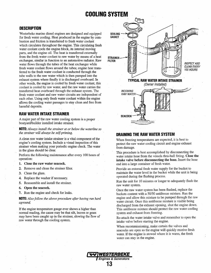
DESCRIPnDN Westerbeke marine diesel engines are designed and equipped SEALING for fresh water cooling. Heat produced in the engine by com- GASKET bustion and friction is transferred to fresh water coolant· which circulates throughout the engine. This circulating fresh water coolant c.ools the engine block; its internal moving parts, and the engine oil. The heat is transferred externally from the fresq water coolant to raw water by means of a heat STRAINER --rJM""' exchanger, similar in function to an automotive radiator. Raw 'FILTER water flows through the tubes of the heat exchanger while fresh water coolant flows around the tubes; engine heat trans-ferred to the fresh water coolant is conducted through the tube walls to the raw water which is then pumped into the exhaust system where finally it is discharged overboard. In other words, the engine is cooled by fresh water coolant, this coolant is cooled by raw water, and the raw water carries the transferred heat overboard through the exhaust system. The fresh water coolant and raw water circuits are independent of each other. Using only fresh water coolant within the engine allows the cooling water passages to stay clean and free from harmful deposits.
RAW WATER INTAKE STRAINER A major part of the raw water cooling system is a proper boatyard/builder installed intake strainer.
NOTE: Always install the strainer at or below the waterline so the strainer will always be self-priming.
A clean raw water intake strainer is a vital component of the engine's cooling system. Include a visual inspection of this strainer when making your periodic engine check The water in the glass should be clear. Perform the following maintenance after every 100 hours of operation: 1. Close the raw water seacock. 2. Remove and clean the strainer filter. 3. Clean the glass. 4. Replace the washer if necessary. 5. Reassemble and install the strainer. 6. Open the seacock. 7. Run the engine and check for leaks.
NOTE: Also follow the above procedure after having run hard agroun4.
If the engine temperature gauge ever shows a higher than · normal reading, the cause may be that silt, leaves or grass
may have been caught up in the strainer, slowing the flow of ·raw water through the cooling system.
TYPICAL RAW WATER INTAKE STRAINER (Owner Installed)
SEA COCK
~
DRAINING THE RAW WATER SYSTEM
INSPECT AND ' CLEAN EVERY
100HOURS
When freezing temperatures are expected, it is best to protect the raw water cooling circuit and engine exhaust
· from damage. This procedure is best accomplished by disconnecting the water intake hose from the vessels thru-hull fitting. Close the intake valve before disconnecting the hose. Insert the hose end into a large container of fresh water. Provide an external fresh water supply for the bucket to maintain the water level in the bucket while the unit is being operated during the flushing process. Run the unit for 10 minutes or longer to adequately flush the raw water system. Once the raw water system has been flushed, replace the buckets content with a 50/50 antifreeze mixture. Run the engine and allow this mixture to be pumped through the raw water circuit. Once this antifreeze mixture is visible being discharged from the exhaust opening, shut the engine down. This antifreeze mixture should protect the raw water cooling system and exhaust from freezing. Re-attach .the water intake valve and remember to open the intake valve before starting the engine. When recommissioning, make certain the valves and seacocks are open so the engine will quickly receive fresh water. If the engine is stowed where it is warm, the fresh water can stay in the engine.
Engines & Generatol"$
13

COOLING SYSTEM
FRESH WATER COOLING CIRCUIT NOTE: Refer to the ENGINE COOLANT section for the recommended antifreeze and water mixture to be used as the fresh water coolant.
Fresh water coolant is pumped through the engine by a circulating pump, absorbing heat from the engine. The coolant then passes through the thermostat into the manifold, to the heat exchanger where it is cooled, and returned to the engine block via the suction side of the circulating pump.
When the engine is started cold, external coolant flow is prevented by the closed thermostat (although some coolant flow is bypassed around the thermostat to prevent the exhaust manifold from overheating). As the engine warms up, the thermostat gradually opens, allowing full flow of the engine's coolant to flow unrestricted to the external portion of the cooling system.
TO COOLANT RECOVERY TANK
KEEP THE COOLANT PASSAGE CLEAR
FROM COOLANTRECOVERY TANK
COOLANT EXPANSION
PRESSURE /CAP
COOLANT RETRACTION
NOTE: Periodically check the condition of the manifold pressure cap. Ensure the upper and lower rubber seals are in good condition. Check to ensure . the vacuum valve opens and closes tightly. Cany a spare cap. Check also to ensure the coolant passage is clear so coolant within. the,system is able to expand and contract SEAL to and from the coolant recove1y tank..
Coolant Recovery Tank A coolant recovery tank allows for engine coolant expansion and contraction during engine operation, without any significant loss of coolant and without introducing air into the cooling system. This tank should 9e located at or ~hove the engine manifold level and should be ea.Sily accessible.
NOTE: 11zis tank, with its short run of plastic hose, is best located at or above tlze level of the engine :S manifold.
CHANGING COOLANT The engine's coolant must be changed according to the MAINTENANCE SCHEDULE. If the coolant is allowed to become contaminated, it can lead to overheating problems.
A CAUTION: Proper cooling system maintenance is critical; a substantial number of engine failures can be traced back to cooling system corrosion.
Drain the engine coolant by loosening the drain plug on the engine block and opening the manifold pressure cap. Flush the system with fresh water, then start th~ refill process.
NOTE: The drain on the heat exchanger should also be us(td to help drain engine coolant.
OIL GALLERY
Refilling the Coolant After closing the engine block drain, pour clean, premixed antifreeze coolant into the open filler neck. When coolant is visible in the filler neck, start the engine. Open the air bleed petcocks when present on the thermostat housing and heat exchanger.
Monitor the coolant in the filler neck and add as needed to keep it filled. Monitor the air bleed petcocks and when clear coolant is flowing from them close each. Top off the filler neck with coolant and install the pressure cap.
Remove the cap on the coolant recovery tank and fill with coolant mix to halfway between LOW and MAX and replace the cap. Run the engine and observe the coolant expansion flow into the recovery tank.
After checking for leaks, stop the engine and allow it to cool. Coolant should draw back into the cooling system as the engine cools down. Add coolant to the recovery tank if needed. Clean up any spilled coolant.
A WARNING: Beware of the hot engine coolant. Wear protective gloves.
Engines & Generators
14

COOLING SYSTEM THERMOSTAT A thennostat, located near the manifold at the front of the engine, controls the coolant temperature as the coolant continuously flows through the closed cooling circuit. When the engine is first started, the closed thermostat prevents coolant from flowing (some coolant is by~passed through a bole in the thermostat to prevent the exhaust manifold from overheating). As the engine warms up, the thermostat gradually opens. The thermostat is accessible and can be checked, cleaned, or replaced easily. Carry a spare thermostat and gasket.
REPLACING THE THERMOSTAT 1. Drain off some coolant: Release the coolant pressure cap ·
and drain the coolant to the approximate level off the · thermostat housing. This can be done using the heat exchanger drain plug.
2. Rotate the thermostat assembly: Loosen the hose clamp as shown and remove the three allen screws that hold down the thermostat housing cover, the assembly can now be twisted enough to access the gasket and thermostat.
3. Remove/replace the gasket and thermostat: When installing the new parts, apply a thin coat of sealant on both side of the gasket before pressing it into place.
HEAT EXCHANGER
~~. / , ~ 4. R,-and~ Thm lhe cov« back intO place>md
THERMOSTAT ASSEMBtY
GASKET SEAL WfTHHI-TACK #052946
COOLANT TEMPERATURE ~NS~R 11035109
~·
.... ....:::::::-:- r tighten the three screws. Do not over-ti.ghten! Tighten the
l~ bose clamp and tighten the drains. Top off the coolant and · run the engine. Check for normal temperature and for any
· leaks around the thennostat assembly: 1 . .
THERMOSTAT HOUSING
A CAUTION: The e1111ine lfiUSI be allowed to cool down before attempting these procedures. Not DIJ.IY is the surface of the engine hot but coolant temperatures can be at 190• F.
Engines & Generators
15

COOLING SYSTEM.
RAW WATER COOUNG CIRCUIT· The raw water flow is created by a positive displacement impeller pump. This pump draws water directly from the ocean, lake, or river through a hose to the water strainer. The . raw water passes from the strainer through the heat exchanger (through the beat exchanger tubes) where it cools the engine ·circulating fresh water coolant. The raw water is then discharged into the water injected exhaust elbow, mixing with and cooling the exhaust gasses. This mixture of exhaust gas and raw water is pushed overboard.
Raw Water Pump The raw water pump is a self-priming, rotary pump with a non-ferrous housing and a neoprene impeller. The impeller has flexible vanes which wipe against a curved cam plate within the impeller housing, producing the pumping action. On no account should this pump be run dry as water acts as a lubricant for the impe1ler. There should always be a spare
·impeller and impeller cover gasket aboard (an impeller kit). Raw water pump impeller failures occur when lubricant (raw water) is not present during engine operation. Such failures are not warrantable, and operators are cautioned to make sure raw water flow is present at start-up.
·-" ' ~·- ··- -· NOTE: Should a failure occur with the pumps internal parts (seals and bearings), it may be more cost efficient to purchase a new pump and rebuild the original pump as aspare. ·
·Inspecting/Changing the Raw Water Pump Impeller Close the raw water intake valve. Remove the pump cover and, with the proper size impeller tool, carefully pry the impeller out of the pump (the impeller can be pried out using 1\ pair of screwdrivers if an impeller puller is unavailable. Take care riot to tear the impeller). Install the new. impeller and
. gasket. ·Move the blades to conform to the curved cam plate and' push the impeller into the pumps housing. When assembling, apply a thin coating of lubricant to the impeller and gasket. Open the raw water intake valve. Run the engine and check for leaks around the pump. Also check for water discharge at the stem tube. Absence of w.ater flow indicates the pump has not primed itself properly.
NOTE: Never allow the pump to run dry. Even a short period of dry running may destroy the impeller.
RAW WATER PUMP PN52650
INSPECTION: CHECK THE BASE OF EACH BLADE BY BENOING VIGOROUSLY. REPLACE THE IMPELLER IF THERE ARE
·ANY CRACKS.
. NEW .BAD
Heat Exchanger PN. 052493
v.~RAW WATER DRAIN -~·······'-----···· . .
-~
CLEAN' AND ' REUSE
ZINC ANODES
The heat exchanger is made up of a copper tube which encloses a number of small cupro-ilickel tubes. Raw water is pumped through these small tubes and antifreeze coolant from the engine is circulated around the tubes. The raw water removes heat from the antifreeze coolant.
Zinc Anode A zinc anode, or pencil, is located in the raw water cooling circuit within the heat exchanger. The putpose of the zinc anode is to sacrifice itself to electrolysis action taking place in the raw water cooling circuit, thereby reducing the effects of electrolysis on other components of the system. The condition ofthe zinc anode should be checked monthly and the anode cleaned or replaced as required. Spare anodes should be carried on board.
NOTE: Electrolysis action is the result of each particular installation and vessel location; not that of the generator.
If the zinc pencil needs replacement, hold the hex boss into which the zinc pencil is threaded with a wrench while loosening the anode with another wrench. This prevents the hex boss from possibly tearing off the exchanger shell. Mter removing the zinc, note the condition of it. If the zinc is in poor condition, there are probably a lot of zinc flakes within
. the exchanger. Remove the end of the heat exchanger and clean the inside of all zinc debris. Always have a spare heat exchanger end gasket in case the present one becomes damaged when removing the end cover. Replace the gasket (refer to your engine model's heat exchanger end gasket part number); a-ring, cover, and install a new zinc pencil.
Heat Exchanger Service After approximately 1000 hours of operation, remove, clean and presSure test the engine's heat exchanger. (A local automotive radiator shop should be able to clean and test the heat
i exchanger.) •: '
·. · NOTE: Operating in sz'lty and/or tropical waters may require ,.,A,rrt:J'...;' that a heat exchanger cleaning be performed more often than
every 1000 hours.
Enf1ines & Generators
16
ENGINE LUBRICATING OIL
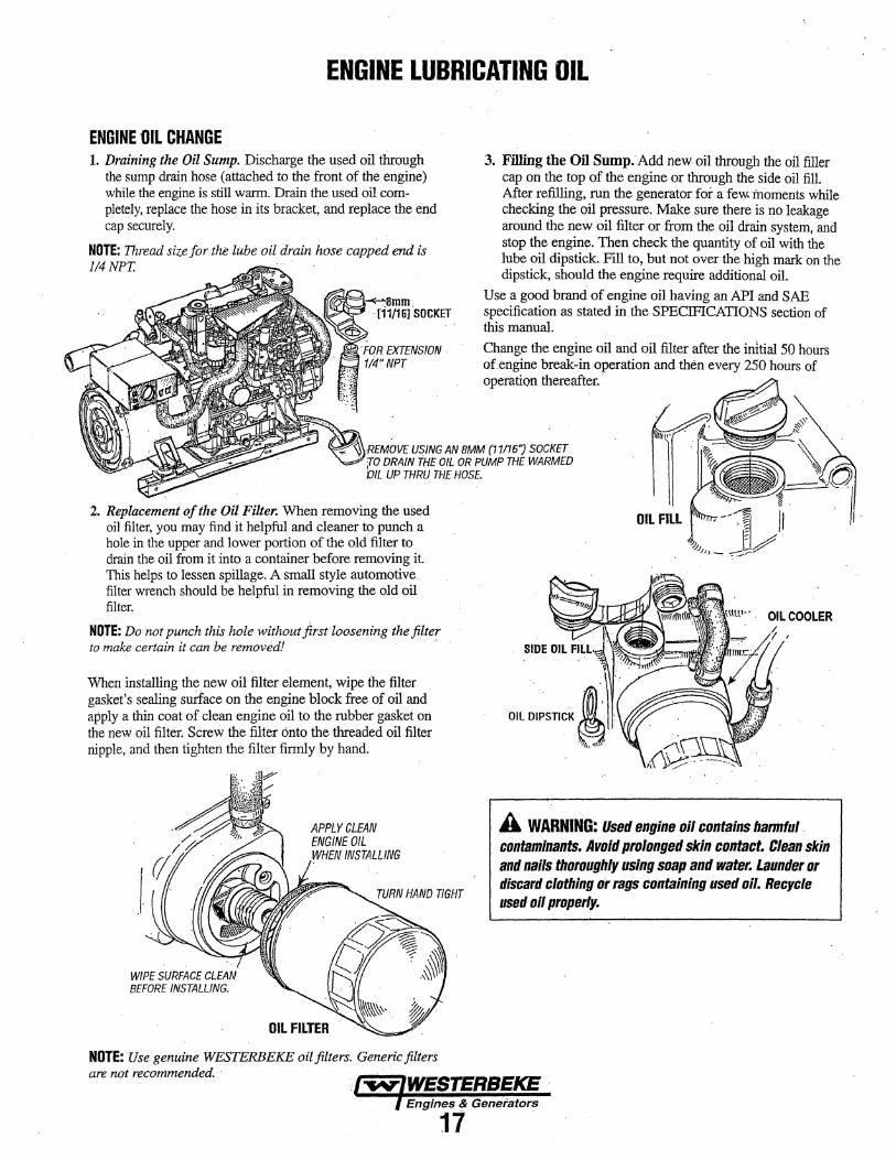
ENGINE {)IL CHANGE 1. Draining the Oil Sump. Discharge the used oil through
the sump drain hose (attached to the front of the engine) while tl1e engine is still warm. Drain the used oil com" pletely, replace the hose in its bracket, and replace the end cap securely.
NOTE: Thread size for the lube oil drain hose capped end is I/4NPT.
3. Filling the Oil Sump.Add new oil through the oil filler cap on the top of the engine or through the side oil fill. After refilling, run the generator for a few. moments while checking the oil pressure. Make sure there is no leakage around the new oil filter or from the oil drain system, and stop the engine. Then check the quantity of oil with the lube oil dipstick. Fill to, but not over the high mark on the dipstick, should the engine require additional oil.
Use a good brand of engine oil having an API and SAE specification as stated in the SPECIFICATIONS section of this manual.
Change the engine oil and oil filter after the initial 50 hours ofengine break~in operation and then every 250 hours of operation thereafter. ·
\IW<CIVIUVI: USING AN BMM (11/16"} SOCKET DRAIN THE OIL OR PUMP THE WARMED UP THRU THE HOSE.
2. Replacemmt of the Oil Filter. When removing the used oil filter, you may find it helpful and cleaner to punch a hole in tl1e upper and lower portion of the old filter to drain the oil from it into a container before removing it. This helps to lessen spillage. A small style automotive filter wrench should be helpful in removing the old oil filter.
NOTE: Do not punch this hole without flrst loosening the filter to make certain it can be removed! ·
When installing the new oil filter element, wipe the filter gasket's sealing surface on the engine block free of oil and apply a thin coat of clean engine oil to the rubber gasket on the new oil filter. Screw the filter onto the threaded oil filter nipple, and then tighten the filter firmly by hand.
WIPE SURFACE CLEAN BEFORE INSTALLING.
APPLY CLEAN ENGINE OIL WHEN INSTALLING
NOTE: Use genuine WESTERBEKE oil filters. Generic filters are not recommended. ·
OIL COOLER
A WARNING: Used engine oil contains harmful. contaminants. Avoid prolonged skin contact. Clean skin and nails thoroughly using soap and water. Launder or discard clothing or rags containing used oil. Recycle used oil properly.
Engines & Generators
17 .
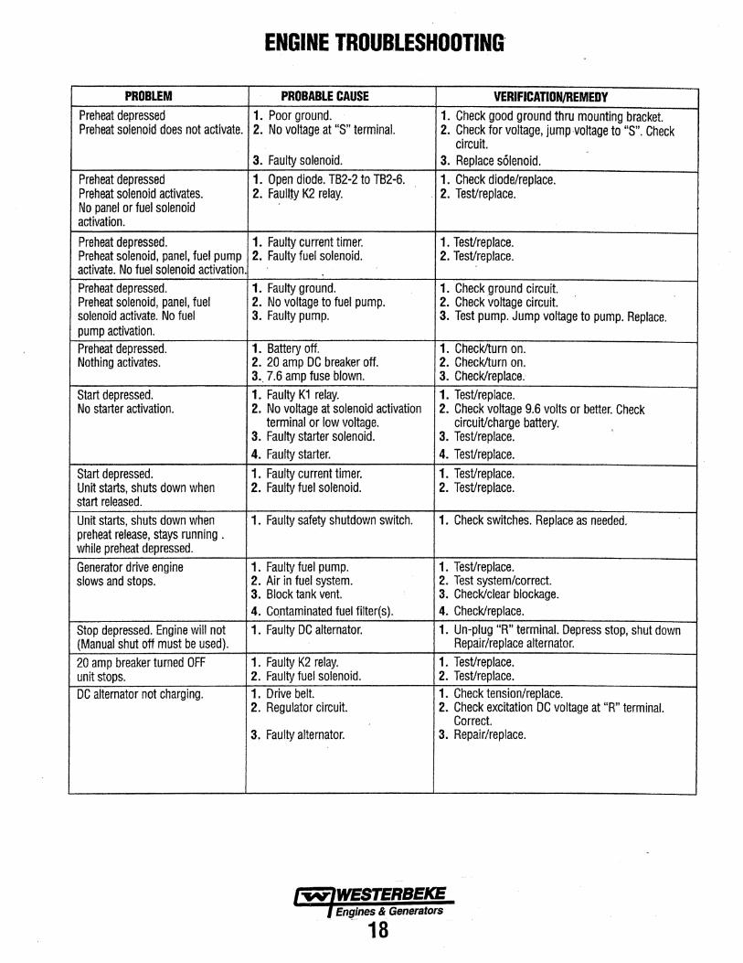
ENGINE TROUBLESHOOTING·
PROBLEM PROBABLE CAUSE VERIFJCAnON,IREMEDY Preheat depressed 1. Poor ground. 1. Check good ground thru mounting bracket. Preheat solenoid does not activate. 2. No voltage at "S" terminal. 2. Check for voltage, jump -voltage to "S". Check
circuit. 3. Faulty solenoid. 3. Replace solenoid.
Preheat depressed 1. Open diode. TB2-2 to TB2-6. 1. Check diode/replace. Preheat solenoid activates. 2. Fau!Jty K2 relay. . 2. TesVreplace. No panel or fuel solenoid activation.
Preheat depressed. 1. Faulty current timer. 1. Test/replace. Preheat solenoid, panel, fuel pump 2. Faulty fuel solenoid. 2. TesVreplace. activate. No fuel solenoid activation. .
Preheat depressed. 1. Faulty ground. 1. Check ground circuit. Preheat solenoid, panel, fuel 2. No voltage to fuel pump. 2. Check voltage circuit. solenoid activate. No fuel 3. Faulty pump. 3. Test pump. Jump voltage to pump. Replace. pump activation. Preheat depressed. 1. Battery off. 1. Check/turn on. Nothing activates. 2. 20 amp DC breaker off. 2. Check/turn on.
3._ 7.6 amp fuse blown. 3. Check/replace.-Start depressed. 1. Faulty K1 relay. 1. TesVreplace. No starter activation. 2. No voltage at solenoid activation 2. Check voltage 9.6 volts or better. Check
terminal or low voltage. circuit/charge battery. ' 3. Faulty starter solenoid. 3. TesVreplace.
4. Faulty starter. 4. TesVreplace. Start depressed. 1. Faulty current timer. 1. TesVreplace. Unit starts, shuts down when 2. Faulty fuel solenoid. 2. Test/replace. start released. Unit starts, shuts down when 1. Faulty safety shutdown switch. 1. Check switches. Replace as needed. preheat release, stays running . while preheat depressed. Generator drive engine 1. Faulty fuel pump. 1. Test/replace. slows and stops. 2. Air in fuel system. 2. Test system/correct.
3. Block tank vent. 3. Check/clear blockage. 4. Co_ntaminated fuel filter(s). 4. Check/replace.
Stop depressed. Engine will not 1. Faulty DC alternator. 1. Un-plug "R" terminal. Depress stop, shut down (Manual shut off must be used). Repair/replace alternator. 20 amp breaker turned OFF 1. Faulty K2 relay. 1. TeSVreplace. unit stops. 2. Faulty fuel solenoid. 2. Test/replace. DC alternator not charging. 1. Drive belt. 1. Check tension/replace.
2. Regulator circuit. 2. Check excitation DC voltage at "R" terminal. Correct.
3. Faulty alternator. 3. Repair/replace.
l"ff'V"iWESTERBEKE Engines & Generators . . -- 18 ..

ENGINE ADJUSTMENTS · DRIVE BELT ADJUSTMENT For your safety, WESTERBEKE generator models come equipped with belt guards that cover the belt(s) on the front of the engine. ("Out of Sight-Out of Mind". The belt guard is NOT installed for that purpose). Operators are advised that proper inspection, service and maintenance is required.
The drive belts must be properly tensioned. Excessive drive belt tension can cause rapid wear of the belt and reduce the · service life of the fresh water pump's bearing. A slack belt or the presence of oil on the belt can cause belt slipping, resulting in high operating temperatures.
The generator has one drive belt that drives the DC alternator. The tension adjustment procedure for the belt is as follows:
A WARNING: Never attempt to check or adjust the drive belt's tension while the engine is in operation.
1. Remove the belt guard.
2. Loosen the alternator adjusting strap bolt and the base mounting bolt.
3. With the belt loose, inspect for wear, cracks, and frayed edges.
4. Pivot the alternator on the base mounting bolt to the left or right as required, to loosen or tighten.
5. The drive belt is properly adjusted if it can be deflected no . less than 3/8 inch (10mm) and no more than 1/2 inch
(12mm) as the belt is depressed with the thumb at the midpoint between the two pulleys on the longest span of the belt.
6. Operate the generator for about 5 minutes then shut down and recheck the belt tension.
7. Replace the belt guard.
FUEL INJECTORS Fuel injectors should be removed for service/rebuild and reinstalled by a competent mechanic. Information regarding fuel injector removal/inspection/rebuild/testing is found in the Service Manual for the models listed in thus manual. An authorized Fuel Injection shop should be contacted when fuel injection is required. Injector servicing at a Fuel Injection shop is performed in a "clean room" environment generally not fo1;1nd in your standard diesel service shop.
Authorized Fuel Injection Repair Shops can be located through your area yellow pages.
NOTE: Clean the area around the base of the injector prior to lifting it out of the cylinder head to help prevent any rust or debris from falling down into the injector hole. If the injector will not lift out easily and is held in by carbon build up or the like, work the injector si9-e to side with the aid of the l7mm deep socket wrench to free it and then lift it out.
TYPICALALTERNATOR ASSEMBLY
TROUBLESHOOTING WATER TEMPERATURE AND OIL PRESSURE GAUGES
If the gauge reading is other than what is normally indicated by the gauge when the instrument panel is energized, the first step is to check for 12 volts DC between the ignition (B+) and the Negative (B-) terminals of the gauge. Assuming that there is 12 volts as required, leave the instrument panel energized( engine on( and perform the following steps:
1. Disconnect the sender wire at the gauge and see if the gauge reads zero, which is the normal reading for this situation.
2. Remove the electrical connection at the sender on the engine and ground it to the engine metal. The gauge should register full scale, which is the normal reading for this situation.
If both of the gauge tests are positive, the gauge is undoubtedly OK and the problem lies either with the conductor from the sender to the gauge or with the sender.
If either of the gauge tests are negative, the gauge is probably defective and should be replaced.
Assuming the gauge is OK, check the conductor from the sender to the sender terminal at the gauge for continuity. Check that the engine block is connected to the ground. Some starters have isolated ground terminals and if the battery is connected to the starter (both plus and minus terminals), the ground side will not necessarily be connected to the block.

ENGINE ADJUSTMENTS NOTE: WESTERBEKE recommends that the following engine adjustments be performed by a competent engine mechanic. The information below is provided to assist the mechanic.
VALVE ADJUSTMENT OIL MANIFOLD
TIMING WINDOW . ( located on the engine bell housing )
TESTING OIL PRESSURE To test the oil pressure, remove the oil pressure sender, then install a mechanical oil pressure gauge in it's place. After warming up the engine, set the engine speed at idle and read . the oil pressure gauge. OIL PRESSURE WILL RANGE BETWEEN 50 AND 55PSI AT 1800 RPM
LOW OIL PRESSURE ·The specific safe minimum oil pressure is 5 - 10 psi. A gradual loss of oil pressure usually indicates wom bearings. For additional information on low oil pressure readings, see the ENGINE TROUBLESHOOTING chart.
CHECKING VALVE CLEARANCE NOTE: Valve clearance must be checked and adjusted when
the engine is cold.
1. Remove the head cover. 2. Align the ITC timing mark on the flywheel (as viewed
thru the timing window on the bell housing) so that the #1 piston comes to the top dead center of its compression stroke.·
3. Loosen the Jock nut (2) and loosen the adjusting screw (1).
4. Loosen the Jock nut and return the adjusting screw. 5. Slightly push the rocker arm (intake side) by your fingers·
and screw in the adjusting screw slowly until you feel the screw touch the top of the valve stem, then tighten the Jock nut.
6. Loosen the lock nut (4) of adjusting screw (3) (push rod side) and insert the thickness gauge between the rocker arm and the bridge head. Set the adjusting screw to the specific clearance, then tighten the lc::k nut.
7. Adjust the clearance between the rocker arm (exhaust side) and the exhaust valve to the specific clearance ..
FACTORY SPEC.
ADJUSTING SCREwS 3
location of piston
When No.1 piston is compression top dead center
When No.1 piston is overlap position
_cylinc!er Adjuslmt.nt
1st
2nd
3rd
4th
1st
2nd
3rd
4th
Tightening torque Cylinder head cover screw
·Enttines & Generators
20
ADJUSTING SCREWS.1
... ... I. ,Y alve arrangement ·
IN.
* *
* *
6.9 to 11.3 N·m 0.7 to 1.15 kgf·m 5.1 to 8.32 ft-lbs
EX.
*
*
*
*
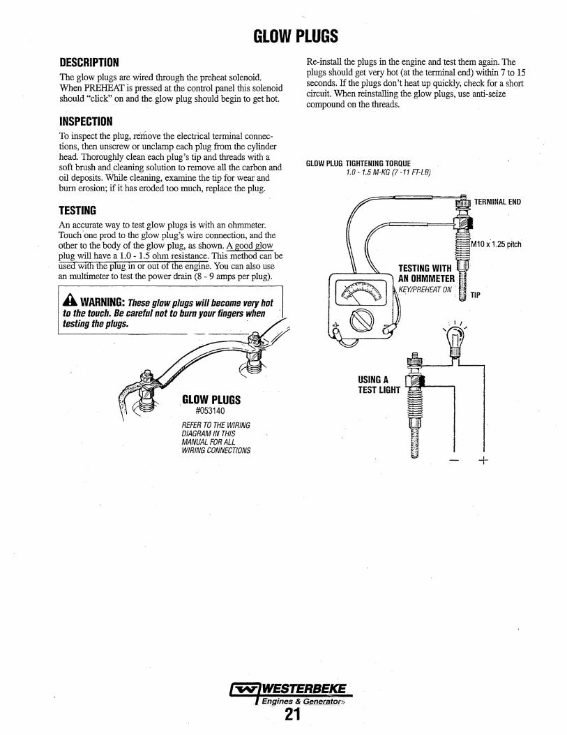
GLOW PLUGS DESCRIPTION The glow plugs are wired through the preheat solenoid. When PREHEAT is pressed at the control panel this solenoid should "click" on and the glow plug should begin to get hot.
INSPECTION To inspect the plug, remove the electrical terminal connections, then unscrew or unclamp each plug from the cylinder head. Thoroughly clean each plug's tip and threads with a soft bru~ and.cleaning solution to remove all the carbon and oil deposits. While cleaning, examine the tip for wear and burn erosion; if it has eroded too much, replace the plug.
TESTING An accurate way to test glow plugs is with an ohnuneter. Touch 'one prod to the glow plug's wire connection, and the other to the body of the glow plug, as shown. A good glow plug will have a 1.0 - 1.5 ohm resistance. This method can be used wtth the plug in or out of the engine. You can also use an multimeter to test the power drain (8 - 9 amps per plug).
A WARNING: These glow plugs will become very hot to the touch. Be careful not to burn your fingers when testing the plugs.
GLOW PLUGS ' #053140
REFER TO THE WIRING DIAGRAM IN THIS MANUAL FOR ALL WIRING CONNECTIONS
Re-install the plugs in the engine and test them again. The plugs should get very hot (at the tetnrinal end) within 7 to 15 seconds. If the plugs don't heat up quickly, check for a short circuit. When reinstalling the glow plugs, use anti-seize compound on !he threads.
GUIW PLUG TIGHTENING TORQUE 1.0-1.5 M-KG (7 -11 FT-LB)
USING A TEST LIGHT
I...,..,.IWESTERIIEKE . ) Engines ~ GJ!.nera.tC!J'S
21

_A~TERNATORS TESTING/TROUBLESHOOTING 1#10 ORANGE 8 TO STARTER SOLENOID
DESCRIPTION
ALTERNATOR · '5DAMP
GROUND
REFER TO THE WIRING DIAGRAM IN THIS MANUAL FOR ALL WIRING CONNECTIONS
'The following inforination applies to the staijdard alternators that are supplied with WESTERBEKE'S Engines and Generators.
ELECTRICAL CHARGING CIRCUIT The charging system consists of an alternator with a voltage regulator, an engine DC wiring batness, a mounted DC circuit breaker and a battery with connecting cables. Because of the use of integrated circuits (IC's}, the electronic voltage regulator is very compact and is mounted internally or on the back of the alternator. It is desirable to test the chargfug system (alternator and voltage regulator) using the wiring harness and electrical loads that are a permanent part of the system and will then provide the technician with an operational test of the charging system as well as the major components of the electl;;ical system. · ·
ALTERNATOR DESCRIPTION ,The stator is connected.to a three-phase,.full-wave bridge rectifiey package which contains six diodes, The bridge · converts the AC generated in the stator to a DC output for battery charging and accessories, Power to the regulator and. the field of the integral regulator alternator is provided by the field .diode (or diode trio) p~kage contained in the alternator.
These alternators produce a rated output of 50 amps. Rated output is achieved at approxiillately 6000 alternator rpm at an ambient temperature of 75° F (23.8° C). The alternators are designed to operate in an ambient temperature range of -40o to 212° F ( -40o to 100° C).
VOLTAGE REGULATOR The integral voltage regulator is an electronic switching device which senses the system voltage level and switches the voltage applied to the field in order to maintain a proper system voltage.
The regulator design utilizes all-silicon semi conductors and thick-film assembly techniques. After the voltage has been adjusted to the proper regulating valve, the entire circuit is encapsulated to protect the circuit and the components from possible damage due to handling or vibration.
ALTERNATOR TROUBLEsHOOTING Use this troubleshooting section to detennine if a problem exists with the charging circuit or with the alternator. If it is determined that the alternator or voltage regulator is faulty, have a qualified technician check it · '
A WARNING: A working altemator runs bot. A failed altematot can beciJIIIB very bot. Do not touch the alternator until if has cooled.
LOW BATTERY/FAULTY CIRCUIT If the starter only moans or makes a clicking sOund instead of spinning the engine to life it is likely a low battery or a faulty connection in the starting circuit and not an alternator problem.
PREUMINARY INSPECTION Before starting the actual alternator and voltage regulator, testing the following checks are recommended. 1. Make certain your alternator is securely mounted. . 2. Check the drive belts for pioper tension. Replace the beh
if it is worn or glazed.
3. Check that all terminals, connectors and plugs are clean and tight Loose or corroded connections cause high resistance and this could c_ause overcharging, undercharging or damage to the charging system. Badly corroded battery cables could prevent the battery from reaching a fully charged condition.
4. Check the condition of the battery and charge if necessary. A low or discharged battery may cause false or misleading readings in the tests.
NOTE: An isolator with a diode, a solenoid, or a battery selector switch is usually mounted in the circuit to isolate the batteries so the starting battery is not discharged along with the house batteries. If the isolator is charging the starting battery but not the hOJlSe btlttery, the altemator is OK and the problem·is i1i the batt~'ry charging circUit. ·
,,.,• I
I..,.,.,.IWESTERBEKE l Enflil)@§..# Gt!P~rators
22

ALTERNATORS TESTING/TROUBLESHOOTING
TESTING THE ALTERNATOR
A CAUTION: Before starting the engine make certain that everyone is clear of moving parts! Keep away from sheaves and belts during test procedures.
1. Start the Engine.
2. Mter the engine has run for a few minutes, measure the starting battery voltage at the battery termimJls using a multimeter set on DC volts.
a. If the voltage is increasing toward 14 volts, the alternator is working.
b. If the voltage remains around 12 volts, a problem exists with either the alternator or the charging circuit; continue with Steps 3 through 6i.
3. Turn off the engine. Inspect all wiring and connection.s. . Ensure that the battery terminals and the engine ground' connections are tight and clean
4. If a battery selector switch is in the charging circuit,ensure that it is on the ·correct battery.
5. Check the battery voltage. If your battery is in good condition the reading should be 12 to 13 volts.
6. Load test the battery if there is a possible issue with weak/faulty cell.
MEASURING BATTERY VOLTAGE
TESTING THE OUTPUT CIRCUIT 1. Connect the positive probe to the output terminal B and
connect the negative probe to ground.
2. Wiggle the engine wiring harness while observing the voltmeter. The meter should indicate the approximate battery voltage, and should not vary. If no reading is obtained, or if the reading varies, check the alternator output circuit for loose or dirty connections or damaged wiring.
3. Start the engine.
4. Repeat the same measurement, the negative probe to ground, ~he positive probe to B with the engine running. The voltage reading should be between 13.5 and 14.5 volts. If your alternator is over or under-charging, have it repaired at a reliable service shop.
5. If the previous test reads only battery voltage at terminal B, use the meter to measure the DC excitation terminal. If 12 volts is not present at exciter terminal R, inspect the wiring for breaks and poor connections. Jump 12 volts from a 12 volt source (such as the battery) and operate the alternator. If the voltage output is 13-14 volts, .. then the alternator is OK.
TESTING THE OUTPUT CIRCUIT ENGINE RUNNING
Engines &. Generators
23
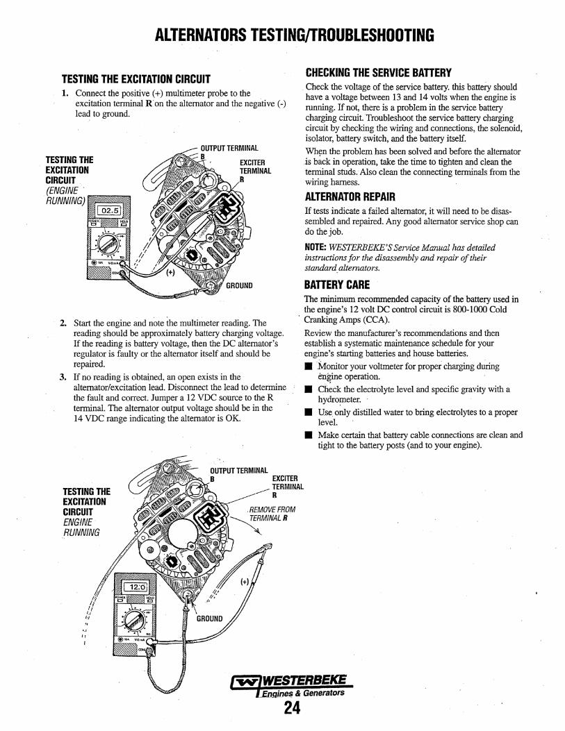
ALTERNATORS TESTING/TROUBLESHOOTING . .
TESTING THE EXCITAnON CIRCUIT 1. Connect the positive ( +) multimeter probe to the
excitation terminal R'onthe alternator and the negative(-) lead to ground.
TESTING THE . EXCITATION
CIRCUIT (ENGINE. RUNNING)
2. Start the engine and note the multimeter reading. The reading should be approximately battery charging voltage. If the reading is battery voltage, then the DC alternator's regulat01; is faulty or the alternator itself and should be repaired.
3. If no reading is obtained, an open exists in the alternator/excitation lead. Disconnect the lead to determine the fault and correct. Jumper a 12 VDC source to the R terminal. The alternator output voltage should be in the 14 VDC range indicating the alternator is OK
OUTPUT TERMINAL EXCITER
CHECKING THE SERVICE BATTERY . Check the voltage of the service battery. this batteiy should have a voltage between 13 and 14 volts when the engine is running. If not, there is a problem in the service battery charging circuit Troubleshoot the service battery charging circuit by checking the wiring and connections, the solenoid, isolator, battery switch, and the battery itself. Whyn the problem has been solved and before the alternator -is hack in operation, take the time to tighten and clean the temiinai studs. Also clean the connecting terminals from the wiring hamess.
ALTERNATOR REPAIR If tests indicate a failed alternator, it will need to be disassembled and repaired. A:n.y good alternator service shop can do the job.
NOTE: WESTERBEKE'SService Manual has detailed instructions for the disassembly and repair of their standard. altenwtors.
BATTERY CARE The minimum recommended capacity of the battery used in the engine's 12 volt DC control circuit is 800-1000 Cold
. Cranking Amps (CCA).
Review the manufacturer's recommendations and then estab:tish a systematic maintenanCe schedule for your engine's starting batteries and house batteries. • Monitor your voltmeter for proper charging during
engine operation. • ch~ck the electrolyte level and specific gravity with a
hydro~eter. · • U.S~. only distilled water to bring electrolytes to a proper
level. • Make certain that battery cable connections are clean and
tight to the battery posts (and to your engine).
TESTING THE EXCITATION CIRCUIT ENGINE· .RUNNING
TERMINAL R
'·' ,,
24

STARTER MOTOR ELECTRICAL TESTING
START
. BATTERY SWITCH
TESTING WITH AN ELECTRICAL JUMPER ~---··REFER TO THE ILLUSTRATION BELOW
NEGATIVE
TYPICAL DIAGRAM
TROUBLESHOOl:ING/INSPECTION Prior to testing, make certain the ships batteries are at full charge and that the starting syste1i1 wiring connections (tenninals) are clean and tight. Pay particular attention to the grmmd wire connections on the engine block.
To check the wiring, try cranking the starter for a few cycles, not more than three crank cycles at a time, then run your hand along the wires and terminals looking for warm . spots that indicate resistance. Repair or replace any trouble spots.
Using a multimeter, test the voltage between the positive terminal stud on the start solenoid and the engine block (ground).
If you rend 12 volts, the srnrter is faulty. If nothing happens at all, the solenoid is not getting current. Check the battery and inspect the wiring connections. It is also possible that the solenoid is defective.
REFER TOTHE.WIRING DIAGRAM IN THIS MANUAL FOR WIRE CONECTIONS .
Remove the Tenninal S wire from the ignition and attach the lead from the electrical jumper. Leave the + positive
·battery att{lched and clip the jumper aligater fitting to that terminal. The push button should crank the starter.
'If the push button fru1s to crank the starter and the batteries · wiring and wired connections have been checked, the starter needs to be removed for service.
· NOTE: This electricaljumper can be fabricated using a standard push button and two connecting wires.
TO REMOVE FOR SERVICE. .1. Turn off the DC battery switch.
, 2. If necessary, remove any components to gain full access to the starter motor.
3. Label and disconnect the wiring from the starter. (Do not allow wires to touch, tape over the terminals).
4. Remove the starter mounting bolts.
: 5. Remove the starter from the engine.ln sbme cases the starter will have to be turned to a different angle to clear obstructions,
NOTE: WESTERBEKE uses an ignition proof starter approved by the U.S. Coast Guard. If it is necessary to replace the starter, purchase a new starter from a WESTERBELE dealer/distributor.·
STARTER/SOLENOID TESTING
Engines & Generator$
25

STARTER MOTOR PN.053295
DESCRIPTION The starting system includes the battery, starter motor, solenoid, and struter button.
. When the struter button on the instrument panel is depressed, current flows and energizes the starter's solenoid coil. The energized coil becomes an electromagnet, which pulls the plunger into the coil, and closes a set of contacts which allow high current to reach the starter motor. At the same time, the plunger also serves to push that starter pinion to mesh with the teeth on the flywheel. ·
To prevent damage to the starter motor when the engine starts, the pinion gear incorporates an over-mmling(one-way) clutch which is splined to the struter annature shaft. The rotation of the mmling engine may speed the rotation of the pinion but not the starter motor itself.
Once the struied button is released, the current flow ceases, stopping the activation of the solenoid. The plunger is pulled out of contact with the battery-to~start cables by a coil spring, and the flow of electricity is intermpted to the starter. This weakens the magnetic fields and the starter ceases its rotation. As the solenoid plunger is released, its movement also pulls the starter drive gear fi:om its engagement with the engine flywheel.
TERMINALS
MOTOR
TYPICAL STARTER MOTOR REFER TO THE Wiff!NG DIAGRAM IN THIS MANUAL
SOLENOID
TROUBLESHOOTING TESTING WITH A SCREWDRIVER Prior to testing, make certain the ships batteries are at full charge and that the starting system v.'iring cormections (te1minals) are clean and tight. Pay particular ;:tttention to the ground wire cOimections on the engine block.
To check the wiring, try crarlkiug the starter for a few seconds, never more than 1 0 seconds at a time, then run your hand along the wires and tenninals looking for wa1111 spots that indicate resistru1ce. Repair or replace mw tr·ouble spots.
Using a multimeter, test the voltage between the positive tenninal stud on the strut solenoid and the engine block (ground).
If you read 12 volts, tl1e starter is faulty.
SOLENOID
IGNITION TERMINAL.r
\
I ( n
To test the·ignition circuit, locate the ignition(s) terminal (it is one of the small tenninal studs and is wired to the ignjtion circuit). Use a screwdriver, don't touch the blade, to jump from that ignjtion tem:linal to the positive battery connection terminal on the solenoid.
If the starter cranks, the fault lies with the ignition circuit. If the solenoid clicks but nothing else happens, the starter motor is probably faulty.
SOLENOID
IGNITION TERMINAL
~ . If nothing at all happens the solenoid isn't getting current. . Check the battery isolation switch and inspect the wiring cmmections. It is also possible that the solenoid is defective.
A WARNING: There will be arching and sparks will fly when jumping terminals. Be certain··the engine space is free of potf#ntially explosive fumes! especially gasoline.
Engines & Generators
26
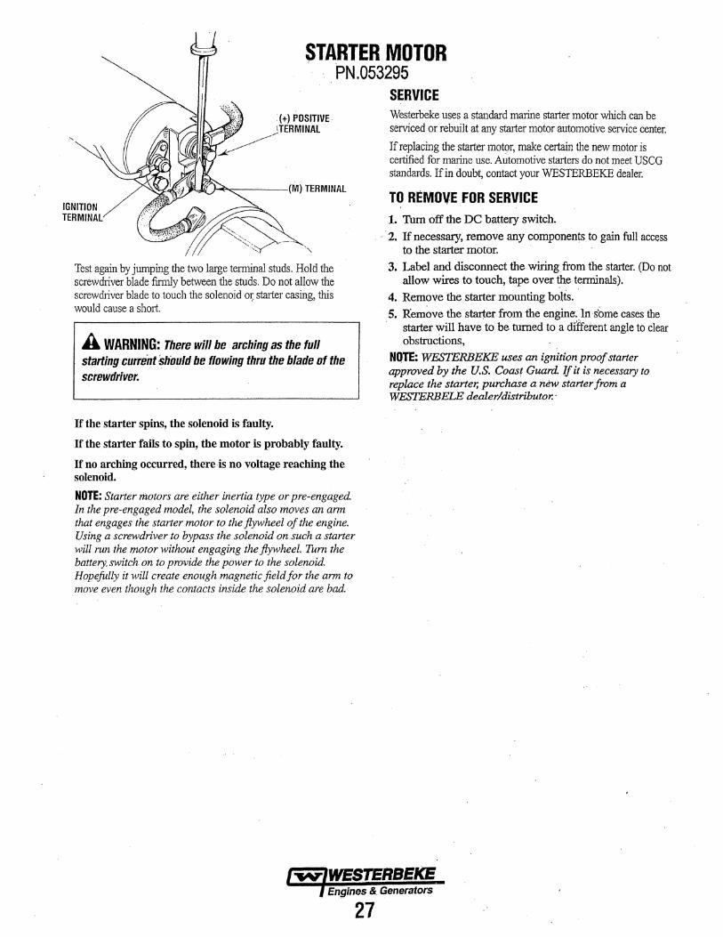
STARTER MOTOR , PN.053295
IGNITION TERMINAL
Test again by jumping the two large temrinal studs. Hold the screwdriver blade finnly between the studs. Do not allow the screwdriver blade to touch the solenoid o~ starter casing, this would cause a short.
A WARNING: There will be arching as the full starting current 5/iould be flowing thru'the blade of the screwdriver.
If the starter spins, the solenoid is faulty.
If the_ starter fails to spin, the motor is probably faulty.
If no arching occurred, there-is no voltage reaching the solenoid.
NOTE: Starter motors are either inertia type or pre-engaged. In the pre-engaged model, the solenoid also moves an arm that engages the starter motor to the flywheel of the engine. Using a screwdriver to bypass the solenoid on such a starter will run the IJWtor without engaging the flywheel. Tum the battery. switch on to provide the power to the solenoid. Hopefully it will create enough magnetic field for the arm to move even though the contacts inside the solenoid are bad.
SERVICE Westerbeke uses a standard marine starter motor which can be serviced or rebuilt at any starter motor automotive service center.
If replacing the starter motor, make certain the new motor is certified for marine use. Automotive starters do not meet USCG standards. If in doubt, contact your WESTERBEKE dealer.
TO REMOVE FOR SERVICE 1. Thm off the DC battery switch.
. ·· · 2. If necessary, remove any components to gain full access to the starter motor.
3. Label and disconnect the wiring from the starter. (Do not allow wires to touch, tape over~ tenninals).
4. Remove the starter mounting b~lts. , 5. Remove the starter from the engine~ ln·sbme cases the · starter will have to be turned to a di'ffetent angle to clear
obstructions, NQTE: WESTERBEKE uses an ignition proof starter approved by the U.S. Coast Guard. If it is necessary to replace the starter, purchase a new starter from a WESTERBELE dealer/distributor.·
1-w'IWESTERBEKE )engines &. Generators
27

RAW WATER PUMP #052650 DISASSEMBLY 1. With the pump removed from the engine, remove cover
#3, the gasket #4 and withdraw the impeller #5. 2. Remove the cam securing screw #10 and remove the
cam#8. 3. Remove the inner wear plate #6. 4. Remove the internal circlip #18. . S. Support the pump housing on a press with the impeller
opening up. · 6. Press the shaft assembly #15, #16-1, #17 and#16-2 out of
the pump housing through the drive end. Spacer #14 and slinger #13 will come out with the shaft: assembly.
7. Remove bearing #16-2 from the shaft, extemal circlip #17 and bearing #16-1.
8. Push shaft water seal #7 out of the pump housing through the impeller opening. Note the orientation of the seal for CGtreetibstallation of the new seal. · · .
ASSEMBLY 1. Assemble bearing #16-2 onto the shaft Install extemal
circlip #17 and position bearing #16-2 so it just contacts the circlip. Install bearing #16-1 onto the sh;rft and
· position ii so it contacts the circlip and bearipg #16-2.
FRONT ASSEMBLY
#2'ENO COVER SCREWS (6) M4x-tox8MM 034463
#6 WEAR PlATE 302574
. . 2. Install the spacer #14 and slinger #13 on the shaft. Warm
the housing so to provide an easier press fit of the shaft/bearing assembly into the housing. Using an appropriate press, press the shaft bearing assembly into the ho'!lsing so that the bearing #16-2 just clears the intemal_ circlip #18 retaining slot ·
3. Install theintemal circlip #18. 4. Press -the shaft bearing assembly so the bearing #16-2 just
contacts the internal circlip #18. Rotate the shaft to ensure no binding.
. S. Apply rome glycerine io the sealing lip of the shaft water seal #7 properly orientated. Using a twisting motion, slide the seal over the shaft until it t9ntacts the recess for the seal in the housing. Then carefully press the seal fully into the recess.
6. Insta,ll the~ wear plate #6 and the cam #8, applying some se8Iant on the cams securing screw #10.
7. Apply some glycerine to the surface of the impeller's housing and install the impeller #5.
8. Apply some glycerine to the vanes of the impeller that · will contact the cover #3. Install the gasket #4 and cover
#3 and secure with the 6 screws· #2. 9. Re-install the pump on the engine.
·.#10 CAM RETAINING SC.REW .053372 ..
- \ . ;:iEE REAR ASSEMBLY BELOW
ROTE: The parts shown along with . a glycerine pi:zck are included in . WESTERBEKE'S PUMP KlT#053375
·~ ,. .
·#16-l-2 . . . . SHAFT BALL BEARING (2)
053366
#18 ;em cuP ........ ,.-. l"ffi!:JWESTERBEKE ~ '!nqi!Jes & (Jenerators ~~~~~P f:irs INTO ·
GROOvE IN PUMP BODY . . . . .

WATER HEATER: {OWNERS OPTION)) INSTALLATION INSTRUCTIONS
WATER HEATER INSTALLATIONS These engines are equipped with connections for the plumbing of engine coolant to transfer heat to an on-board water heater. The water heater should be mounted in a convenient location either in a high or low position in relation to the engine, so that the connecting hoses from the heater to the engine can run in a reasonably direct line without any loops which might trap air. Hoses should rise continuously from their low point at the heater to the engine so that air will rise miturally from the heater to the engine. If trapped air is able to rise to the heater, then an air bleed petcock must be installed at the higher fitting on the heater for bleeding air while filling the system.
THERMOSTAT HOUSING
---,.;·..-- .
NOTE: If any portion of the heatine circuit rises above the engine's own pressure cap, then a pressurized'(aluminum) remote expansion tank (Kit #024177) must be installed in the circuit to become the highest point. Tee the remote expansion tank into the heater circuit, choosing the hisher of the two connections for the return. Tee at the heater, and plumb a single line up to the tanks location and the other back to the engine's return. Install the remote expansion tank in a convenient location so the coolant level can easily be checked. The remote expansion tank will now serve as a check and system fill point. The plastic coolant recovery tank is not used when the remote expansion tank kit is installed, since this tank serves the same junction. Remove and store the plastic recovery tank if it has been already installed.
The pressure cap on the engine's manifold should be installed after the engine's cooling system is filled with coolant. Finish filling the cooling system from the remote tank after the system is filled and is free of air and exhibits good coolant circulation. During engine operation, checking
. the engine's coolant should be done at the remote tank and not at the engine manifold cap. The hose connection from the heater to the remote expansion tank should·berouted and supported so it rises continuously from the heater to the tank, ~nabling any air in tl:}e s}'stem to rise up to the tank and out of the system.
NOTE: An air bleed petcock is located on the engine :r thennostat housing. Open this petcock when filling the engine's co,oling system. This will help to allow air to vent from the cooling system as coolant is added.
_.....,...- OWNERS HOT WATER HOSE FROM HOT WATER TANK.
WATER HEATER CONNECTIDNS
_ ...
OWNERS HOT WATER HEATER (TYPICAL)
Engines & Generators
29

REMOTE OIL FILTER (OPTIONAL) PN:054372
APPLY A THIN COAT OF CLEAN OIL TO THE O·RING WHEN INSTALLING THIS KIT. THREAD THE KIT ON, THEN HAND TIGHTEN AN AODITIONAl3/4 TURN AFTER THE 0-RING CONTACTS THE BASE. . .
THE "OUT" CONNECTION HOSE MUST ATTACH TO THE "IN" CONNECTION AT THE REMOTE OIL FILTER.
INSTALLATION
NOTE; The "ln nand "out" ma1*im1s~ on the kit (if the hoses are n:muvo:••.:.• for /nstallationJ so they can be ~conndCt&d correctly.
This popular accessory 'is. used to relocate the engine's oil filter from the engine to a more convenient location such as an engine room bulkhead. · ·
NOTE: Refer to ENGINE OIL CHANGE in this manual for in.Structions on removing the oil filter. To install, simply remove the engine oil filter and thread on WESTBRBEKE's remote oil filter kit as shown. Always -install. this kit with the oil filter facing down as illustrated. Contact your WESTERBEKE dealer for more information.
APPLY A THIN COAT OF CLEAN OIL TO THE FILTER GASKET WHEN INSTAlLING. AFTER THE FILTER CONTACTS THE BASE. tighten It firmly by hand ·
A CAUTION: It is vital to install the oil lines cori'Bctly.,Jf the oil flows in the reverse direction, the by-pass valve in the filter asembly will prevent the oil from reaching the engine, causing an intemal engine failure. If there is no oil pressure reading, shutdown immediately and check the hose connections.
'(OPTIONAL) BLOCK HEATER PN:055667 (120V)
DESCRIPTION A Block Heater can be installed in the engine block in place of the Block Drain plug which is located on the side of the engine block next to the side oil fill. The Block Heater kits include the power cord and contain items needed to install the heater with illustrated instructions. Contact your WESTERBEKE DEALER for more information ..
NOTE: The Block Heater must always be immersed in coolant and the Block Heater can not be operated with the engine rnnning.
(REMOVE TO INSERT BLOCK HEATER)
PN:055668 (240V)
v .
· ·ADAPTER ~ PN:055666
.~})).W .
BLOCK HEATER KIT 240V PN:055668 INCLUDES A 6'(1.83M) POWER CORD WITH A SCHUKA PLUG (CEE 7/7 230V)
BLOCK HEATER KIT 120V PN:055669 WITH POWER CORD
fY.T{WESTERBEKE. Enaines & Generators
30

SPECIFICATIONS • GENERATORS 29.0/23.0 EGED
Engine Type
Aspiration
Compression Ratio
Governor
Combustion Chamber
Bore & Stroke
Piston Displacement
Firing Order :
Inclination
Weight (dry)
GENERAL Diesel. four-cycle. four-cylinder. fresh water-cooled, vertical in-line overhead valve mechanism.(42 hp at 1800 rpm maximum).
Naturally aspirated.
22.6:1
Electronic
Swirl type.
98 x 110 mm (3.86 x4.93 inches)
3.62 liters (220.9 cubic inches)
1 - 3- 4 -2
Continuous 20° Temporary 30° (not to exceed 10 min.)
11351bs (514.8 kgs)
TUNE-UP SPECIFICATIONS Compression Pressure (allowable limit)
Variation between cylinders
Injection Timing
Engine Speed
Valve Clearance (engine cold)
Injector Pressure
Valve Timing
626 psi ( 44 kg/em') at 250 rpm (472 psi (30.5 kg/em')
10% or less
9·sroc 1800 rpm 60 Hertz 1500 rpm 50 Hertz
0.23-0.27 mm (0.00091-0.01 06)
1991- 2134 psi (140 -150 kgf/cm').
Intake Opens 14° BTDC Intake Closes 36° ABDC
Exhaust Opens 45° BBDC Exhaust Closes 17o ATDC
ELECTRICAL SYSTEM Starting Battery
Battery Capacity
DC Charging Alternator
Starter
Starting Aid
Cold Cranking Current
12 Volt DC H negative ground
800- 1000 Cold Cranking Amps (CCA}
50 Amp rated. belt-driven
2.5Kw. 12 VDC direct drive
Glow plugs. sheathed type
150- 200 amps (includes glow plugs)
lUBRICATION ·SY.STEM General
Oil Filter
Sump Capacity (not including filter)
Operating Oil Pressure (engine hot)
Oil Grade
Pressure fed system with external relief valve.
Full flow, paper element. spin·on type.
14.0 U.S. qts (13.2 liters)
28- 57 psi (2.0- 4.0 kg/em')
API Specification CF. CG-4. or Cl-4 SAE 10W·40 or 15W-40
General
Operating Temperature
Fresh Water Pump
Raw Water Pump
Raw Water Flow at 1800 rpm.
System Capacity (Fresh Water)
General
Fuel
Fuel Injection Pump
Fuel Injection Timing
Injector Nozzle
Fuel Filter
Air Intake
Air Flow Combustion
COOLING SYSTEM Fresh water-cooled engine block, Ulermostatically-controlled with heat exchanger.
160° - 180° F (71 o - 82° C)
Centrifugal type, metal impeller, belt-driven.
Positive displacement, rubber impeller, gear-driven.
i 1.0 US gpm (41.6lpm).
16.0 qts (15.11iters)
FUEL SYSTEM Open flow. self bleeding - self priming (electromagnetic fuel pump)
No. 2 diesel oil (cetane rating of 45 or higher).
Bosch type mini pump
gosmc Bosch throttle type.
Spin-on Type
Metal screen/intake silencer !Jox
115 cfm (3.2 cmm) at 1800 rpm
GENERATOR COOLING Air Requirements (generator cooling)
0.8 Power factor unit. 500 CFM (15.0 CMM)
NOTE: Increase cooling air flow 15% tor for slower turning 50 Hertz units.
Generator Compartment Ambient Temperature Recommendations
Single Phase
Single Phase
Voltage- 3 Phase
Voltage regulation:
Frequency regulation:
122°F (500C) maximum
NOTE: Forced ventilation should be provided to maintain generator compartment temperature below 122'F (50°C)
AC GENERATOR Brushless. four-pole revolving field. sealed lubricated, single bearing design. 12 wire reconnectable, with solid-state voltage regulator.
Reconnectable to Double Delta
120 or i 20/240 Volts - 60 Hertz 230 Volts- 50 Hertz
± 2% no load to full rated amperage outlet.
± .3 Hertz (.5%) no load to fu!l rated amperage outlet.
Engines & Generators
31

SPECIFICATIONS 29.0/23.0 EGEO AC GENERATOR (Single Phase) AC GENERATOR (3 Phase)
Single Phase Brushless, six-pole, revolving field. Three Phase Brushless, six-pole, revolving field. Sealed Seal lubricated, single bearing design. lubricated, single-bearing design. 12 Lead 12 lead reconnectable, (Double Delta for reconnectable. Solid state voltage regulator. 120/240 volts, 60hz.) (Series Star for 230
Voltage - 3 phase Low Voltage WYE 240 Volts volts, 50hz) with solid state regulator. (60 Hertz) High Voltage WYE 480 Volts
Voltage 120 or 120/240 volts- 60 hertz DELTA 277 Volts 230 Volts - 50 Hertz
Voltage - 3 Phase High Voltage WYE 400 Volts Voltage Regulation ±2% no load to full load. (50 Hertz) DELTA 230 Volts
Frequency Regulation 3 Hertz (.5%) no load to full load. Amperage - 3 phase Low Voltage WYE 87.3Amps
Rating (Volts AC) (60 Hertz) High Voltage WYE 43.6 Amps
DELTA 75.6 Amps 60 Hz (1800 rpm) 120 volts 275 amps
120/240 volts 275/137.5 amps Amperage - 3 phase High Voltage WYE 41.5 Amps (50 Hertz) DELTA 72.2 Amps
50 Hz (1500. rpm) 230 volts 113 amps
Generator Cooling 500 cfm (14.1 cmm) Generator Cooling 500 cfm (14.1 cmm) Air requirements
Air requirements (60hz at 1800 rpm) NOTE: Increase air supply 15% for 50 Hertz (Single & 3 phase) NOTE: Increase air supply 15% tor 50 Hertz operation (1500 rpm)
operation (1500 rpm)
Generator Compartment 122°F (50°C) maximum Generator Compartment 122°F (50°C} maximum Ambient Temperature
Ambient Temperature Recommendations NOTE: Forced ventilation should be provided Recommendations NOTE: Forced ventilation should be provided to maintain generator compattment
to maintain generator compattment temperatures below 122"F (50•C). temperatures below 122°F (50°C).
Engines & Generators
32

GENERATOR INFORMATION USE OF ELECTRIC MOTORS The power required to start an electric motor is considerably more than is required to keep it running after it is started. Some motors require much more current to start them than . others. Split-phase (AC) motors require more current to start, under similar circumstances, than other types. They are commonly used on easy-starting loads, such as washing machines, or where loads are applied after the motor is started, such as smail power tools. Because they require 5 to 7 times as much current to start as to run, their use should be avoided, whenever possible, if the electric motor is to be driven by a small generator. Capacitor and repulsion-induction motors require from 2 to 4 times as much current to start as to run. The current required to start any motor varies with the load connected to it. An electric motor connected to an air compressor, for example, will require more current than a motor to which no load is connected.
In general, the current required to start 115-Volt motors connected to medium starting loads will be approximately as follows:
MOTOR SIZE AMPS FOR AMPS FOR (HP) RUNNING STARTING
(AMPERES) (AMPERES) 1/6 3.2 6.4 to 22.4* 1/4 4.6 9.2 to 32.2* 1/3 5.2 1 0.4 to 72.8* 1/2 7.2 14.4 to 29.2* 3/4 10.2 20.4 to 40.8 • 1 13 2.0 to 52
*NOTE: In the above table the maximum Amps for Starting is more for some small motors than for larger ones. The reason for this is that the hardest starting types (split-phase) are not made in larger sizes.
Because the heavy surge of current needed for starting motors is required.for only an instant, the generator will not be damaged if it can bring the motor up to speed in a few seconds. If difficulty is experienced in starting motors, turn off all other electrical loads and, if possible, reduce the load on the electric motor.
Required Operating Speed . Run the generator first with no load applied, then at half the generator's capacity, and finally loaded to its fuil.capacity as indicted on the generator's data plate. The output voltage should be checked periodically to ensure proper operation of the generating plant and the appliances it supplies. If an AC voltmeter or ampere meter is not installed to monitor voltage and load, check it with a portable meter and amp probe~
NOTE: When the vessel in which the generator is installed contains AC equipment of 120 volts only, it is recommended that the generator's AC terminal block be configured to provide one 120 voltAC hot leg for the vessel's distribution panel. This will ensure good motor starting response from the generator.
Generator Frequency Adjustment Frequency is a direct result of engine/generator speed, as indicated by the following:
• When the generator is run at 1800 RPM, the AC voltage output frequency is 60 Hertz.
• When the generator is run at 1500 RPM, the AC voltage output frequency is 50 Hertz.
Therefore, to change the generator's frequency, the generator's drive engine's speed must be changed. A reconfiguration 6f the AC output connections at the generator is also neces-
,sary.
Generator Maintenance • Maintaining reasonable cleanliness is important.
Connections of terminal boards and rectifiers may become corroded, and insulation su:faces may start conducting if salts, dust, engine exhaust, carbon, etc. are allowed to build up. Clogged ventilation openings may cause excessive heating and reduced life of. windings.
• For unusually severe conditions, thin rust-inhibiting petroleum-base coatings, should be sprayed or brushed over all surfaces to reduce rusting and corrosion. Typical materials suggested are Daubert Chemical Co. "Non-Rust AC-41 0" and Ashland "Tectyle 506" or equivalent.
• In addition to periodic cleaning, the generator should be inspected for (a) tightness of ail connections, (b) evidence of overheated terminals and (c) loose or damaged wires.
• The drive discs on single bearing generators should be checked periodically if possible for tightness of screws , and for any evidence of incipient cracking failure. Discs
. should not be allowed to become rusty because rust may accelerate cracking. The bolts which fasten the drive disc to the generator shaft must be hardened steel SAE grade 8, identified by 6 radial marks, one at each of the 6 corners of the head.
• The rear armature bearing is lubricated and sealed; no maintenance is required. However, if the bearing becomes noisy or rough-sounding, have it replaced.
• Examine bearing at periodic intervals. No side movement of shaft should be detected when force is applied. if side motion is detectable, bearings are wearing o:r wear on shaft of bearing socket outside bearing has occurred. Repair n;mst be made quickly or major components will rub and cause major damage to generator.
The generator's data plate gives the voltage,current, and frequency rating of the generator. An AC wiring decal is on the inside of the louvered cover at the generator end that includes the AC voltage connections. These voltage diagrams are also shown on these pages.

TWELVE LEAD WINDING/TERMINAL BOARD CONNECTIONS
(SERIES WYE) L
SERIES 2 STAR 3 N
L 5
10::11 2-3 6-7 4-8-12 0 0 0 1 5 9
L1 L3 N
50 Hz L-L 400 volts 50 Hz L-N 230 volts 60 Hz L-L 480 volts 60 Hz L-N 277 volts
PARALLEL DELTA
L
. 10-1~
L1
~· 5 7
L2
L
6-8
9 11
l3
50 Hz L-L 115 volts 60HzL-L 138 volts
DOUBLE DELTA
a-WIRE. 7 10
L
0
L ,._4--:....:;j.~--,~ l
8-11 2-3 . 6-9 0 0
AND (NOMINAL) VOLTAGES
(PARALLEL WYE) 113 L
PARALLEL " STAR
L
10-12
SINGLE PHASE PARALLEl ZIG-ZAG
7 5
L,.2 L3 N
50 Hz L-L 200 volts 50 Hz L-N 115 volts 60 Hz L-L 240 volts 60 Hz L-N 138 volts
L N
10-12 ,.-{'-'--~
2-4 ij 1 3 5 7 9-11
N 1..1 L2
50 Hz L-L 230 volts 50 Hz L-N 115 volts 60 Hz L-L 277 volts 60 Hz L-N 138 volts (Refer to Note #1)
l
0
0
o· Note #1 Single phase amperage load. The phase current must not exceed the nominal value.
1 10 5 12
f t · L2 N L1
50 Hz L-L 230 volts 50 Hz L-N 115 volts 60Hz L-L 240 volts 60Hz L-N 120 volts
Note #2 1111-ee phase zig-zag connection, The rated pm11er must be multiplied by 0.866.
34
L
SERIES v DELTA 10
9 ~ L 8 7 N
10-11 .. 2-3 ·o 6-7 0 0
5-4
l-1· L2 L3 50 Hz L-L 230 volts 50 Hz t-N 115 volts 60Hz L-L 277 volts 60Hz L-N 138 volts (Refer to Note #1)
L\!_ THREE PHASE 'i; 2
ZIG-ZAG ~L
. 10, . 4 6 5
l .s
8-10 2-12 4-6
L
0
0 0 0 3-7-11
b 5 9 r Q I t ' l1 L2 L3 N
50 Hz L-L 346 volts 50 Hz L-N 200 volts 60Hz L-L 415 volts 60 Hz L-N 240 volts (Refer to Note #2)
DOUBLE DEJ.TA a-WIRE.·
L
8-11 2-3 6-9 0
~ 0
1 10 5 12 7 4
N L1 50 Hz L-N 230 volts 60Hz L-N 240 volts
10
o·
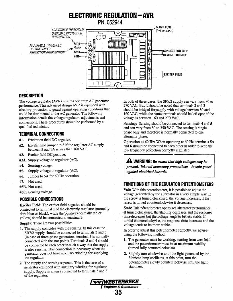
ELECTRONIC REGULATION-AVR PN. 052944.
OLD 'N
ADJUSTABLE THRESH OVERLOAD PROTECTJO = o·
:QO · 0 1 .. 1
/
. SAMP.FUSE 54456) (PN.O
I'NTERVE'NTIO'N · .
I·'---' z~
1--l
.. -~
ADJUSTABLE THRESHOLD . HAmrfzp OF UNDERSPEED _;./' e PROTECTION J'NTERVfNTIO'N : stab
volt
~~ «iil oo: B G;)::e· . """"' 7
~~. . :::: ~ ~!i!' 0 0::: ~ :~
CONNECT FOR 60Hz REMOVE FOR 50Hz
1-
1-
r-
~~::0 D ..
DESCRIPnON The voltage regulator (AVR) ensures optimum AC generator . ·Performance. This.advanced design AVR is equipped with circuitry protection to guard against operating conditions that could be detrimental to the AC generator. The following information details the voltage regulators adjustments and connections. These procedilres should ~ performed by a qualified technician.
TERMINAL CONNECTIONS #1. Excitation field DC negative. #2. Exciter field jumper to 3 if the regulator AC supply
between 5 and 3A is less than 160 VAC. #3. Exciter field DC positive, #3A. Supply voltage to regulator (AC), #4. Sensing voltage. #5. Supply voltage to regulator (AC). #6. Jumper to SA for 60 Hz operation. #7. Not used. #5B. Not used. #5C. Sensing voltage.
POSSIBLE CONNECTIONS ExCite~ Field: The exciter field negative should be connected to terminall of the electr9~ regulator (poJ1.llally . dark blue Or black}. while the '{jositi~~'trtbrmally red or ·. . . . yellow) should be ponnected to tehninal3. Supply: There are two possibilities. 1. The supply coincides with the sensing. In this case the
· SR7/2 supply should be connected to terminals 3 and 5 (in case of three-phase generators, terminal 5 is normally connected with the star po,int). Terminals 3 and 4 should be connected to each other in such a way that the supply is also sensing. This connection in necessary when the
. generator does not have auxiliary winding for supplying the regulator.
2. The supply and sensing separate. This is the case of a generator equipped with auxiliary winding for regulator supply. Supply is always connected to terminals 3 and 5 of the regulatm:.
0 [
,......$.: . ....... ~ D ~ 4-
I: "'-f4 J:::..l
EXCITER FIELD
I . .
In both of these cases, the SR7/2 supply can vary from 80 to 270 VAC. But it &J:wuld be noted that terminals 2 and 3 should be bridged 'fer; supply with voltage between 80 and · 160 VAC, while the Sa.riie terminals should be left open if the voltage is between 160.~d. 270 VAC.
· Sensing: · Sensing shouldbe~connected to termimtls 4 and 5 and can vary from 80 to 3SOVAC. The sensing is single phase only and therefore is normally connected to one · alternator phase. Operation at 60 Hz: When operating at 60Hz, terminals SA and 6 should be conne<;ted to eaeh other in order to keep the low frequency J?!Otection correctly regulated.
A WARNING: Be aware that high voltages may be present. Take all necessary precautlo"- . to sate guard against electrical hazarils.
FUNCTIONS OF THE REGULATOR POTENTIOMETERS Volt: With this potentiometer, it is possible to adjust the voltage generated.by the alternator in a very simple way. If the screw is turned clockwise, the voltage increases, if the screw is turned counterclockwise it decreases. Stab: This potentiometer optimizes'altemator performance.
·.Ifti!irie(i ~loC~se,~the:·~ility ~reases.and the response :. time~~but.thif:;vofta ·· teilds.t6-beless stable. If ' ..... , ............ ' . ge . .. . .
tumecf coiiiiterdlock:Wise, the response litfie increases and the voltage tends to be more stable. In order to a~just this potentiometer correctly;·w~a4~se· using the following method. 1. The g~erator must be working, starting from zero load
· and the potentiometer must be at maximum stability (turned fully counterclockwise).
2. Slightly tum clockwise until the light generated by the filanient lamp oscillates, at this point. tum the potentiometer slowly counterclockwise until the light stabilizes.
I""'IV.jfYESISRBEKE {EngJ.nes ~ (i.enerators

ELECTRONIC REGULATION- AVR CONTROL PANEL
REFER TO THE COMPLETE WIRING DIAGRAM #52951 IN THIS MANUAl.
TERMINAL BLOCK
l
Hertz: With this potentiometer, which is normally pre-calibrated then sealed by the manufacturer, it is. possible to adjust the low frequency protection intervention. To. recalibrate tlus protection, you must take the generator'to a normal zero load condition, tum the potentiometer clockwise until the limit position is reached, then decrease the nominal speed by 10 %. Then turn the potentiometer counterclockwise and measure the voltage value until it has decreased by 5 volts.
TERMINAL BL()CK CONNECTIONS SHOWN ARE CONFIGURED fOR ~ARALLEL·WYE 190/208 VAC
REHR TO 56481 fOR OTHER ill] : Ll,
i r;; CONfIGURATION omONS
. = [g)
!ill &.. -AVR MODEL SR7 0 0
0 ~ tf,IH1'
When the speed decreases by more than 10% of the nominal value, the voltage also decreases proportionally, blocking generator overheating. Even ifwe.,advise calibrating this. protection at 10% of the nominal value, it is obviously possible to calibrate the threshold at other values. · 11 f5'IDOii:1 12
'----;.9.:...-t;! i 10
Amp: With this potentiometer, it is possible to adjust the intervention level of the overload protection. This protection system has an intervention delay, which permits a temporary overload, necessary when starting motors or similar applications. To modify tlus protection, you must overload the generator by 15% of the normal load, tum the potentiometer to minimum (counterclockwise) and wait about twenty seconds. During this period of time the voltage value decreases. In this condition and while turning the potentiometer clockwise, fix the generator voltage value at 10% less than the nominal one. At this point, while the initial overload is being removed, the voltage increases to the nominal value. Fuse: The electronic regulator is equipped with a fuse, which
I I I I :::l!L_ '---0---' J"""c;:3 ~
=
1 • ': 8
s I I 6
EXCIT£R r-----, ~B~LU ___________ +-;~-~=·=r+~~
~. I BLU -.rEt i ' Circuit '-----._... _ __.
Breaker DC Field
protects the alternator from overheating in cases of regulator ....,..~- --. malfunction. The fuse (250V.:.5A, quick acting, F type) can be l C STATOR l replaced easily. 2:========~·tf:::~i====== -----------, -~~ I ~ I r_:_. _ _j ___ -:- ___ __.; __ 1
1 I I I s:::;;;;;;;;;;;:H:::::4=====::7 I EXCITER 1 I 1 · 6 t- s
I A l I I 4):=t~~~c::t=t:::t:==~3 l t I I 2---] 1 I . I I 1 I I I I I I I I I I I I I I t I L---~-----------1 ----------- · ·'FUsE
:J 50Hz
VOLTAGE REGULATOR ~L.T~B~.L~UE~#~16~ .. -. ----~--~----r--~~
YEllOW YELLOW#1&.
~ ....
RED
RED
. Ef!gin~ & Generators
36
JNTEBNAL WIRING DIAGRAM 12 ·wiRE RECONNECT ABLE
WITH SR7·2G AVR
.

INTERNAL WIRING SCHEMATIC EXCITER ROTOR/ROTATING FIELD
NOTE: A booklet "BE GENERATORS" Ele~tri~al Testing & Troubleshooting Guide. A basic gut~e ts available in pdf form to download off our webstte www. westerbeke.com
EXCITER ROTOR ; WINDINGS
GREER
ISOlATION DIODE PlATES
AC. OUJPUJ- CDNFIGQRAliO __ N S_· - . .
"$ERIE$·~
. :480Y l60l'!z 40QYI/50Hz· ·
"PARALLEL. WYE" zo8V/66Hi 200V150Hz
*CONNECT AC BOND WIRE IF REQUIRED BY LOCAL REGlJLAT IONS
0 6+9
0 8+11
'"DOUSU! DELTA" 13·WIRI!!. SPIJT SlliiOLI'! PHASE!
120·240V /60Hz 11 0· 230V /~QHz
RED
TRANSIENT
----i I I I I I I
"SEFjlE$ DELTA" i40V/60Hz 230V/50Hz
+
"'PARAL.U!L DELTA" 12oV/60Hi 115V/50Hz
""DOIJBI.E DEl. TA" (2·WIRE SINGLE PI:!ASEI
Z40V/60HZ 230Vi50Hz
EOE I-PHASE I 3·PHASE
37

SHORE POWER TRANSFER SWITCH CONNECTION.S If the installer coimects shore power to the vessel's AC circuit, this must be done by means of the SHORE POWER/ OFF/SHIPS GEN. Set the transfer sWitch shown in the diagrams to the OFF position. This switch prevents simultaneous connection of shor~ power to generator output.
A CAUTION: Damage to the generator can resuit if utility shore power and generator output are connected at the same time. This type of generator damage is not covered under the wauanty; it is the installer's responsibility to make sure all AC connections are correct.
A CAUTION: Heavy motor.foads should be shut oU before switching shore power to !{enerator power or vfce~versa because voltage surges induced by switching with heavy AC loads on the vessel being operated may cal/SI1 damage to the exc11er circuit components In the generator.
Shore Power Connections (60 Hertz) GENERATOR
Ship to Shore SWitch (3 Pole)
---, I I I I I I I l
~ ..... _ _/
t ~ T oR-=o""'u~ND~..._---IIII•
230 Volt/50 Hertz Two Wire Configur.ation Notice the repositioning-of. the white ground lead on the terminal block to the generator case.
N Ship to Shore Switch· · -GENERATOR
GROUND .u
~ GENERATORiSHORE ::J SWITCH = ,-,
" ' '-----+{'1 ~f-l>'-___...1l1 I I
r-----3----+{3) ' 2 I ' , .. _ ....
.... -.. . . _...". ~'....,____.,___,. • N
(NEUTML)• I. ·~ ,.....:-----t.~. 7 ' ,
. '. , ,_,. .
SHIP'S LDAO
SHORE ll1 N J . '=' GROUND
SHIP'S -=- .GROUND
T
SHORE POWER L1230V 50Hz
SHORE POWER TRANSFER SWITCH AND ,CONNECTION SHOWN ARE FOR SINGtE PHASE ONLY
~. SHORE PO.WER NOTE: SHIP TO SHORE SWITCHES ARE AVAILABLE AT YOUR WESTERBEKE DEALER.
NOTE: Diagram shows connections' for a two-wire, 120 volt system. For a three-wire system. use the dotted lines for the other hot leg.
(-w'lqBIERBEKE ) Eng/!J~~·~· Generators
38

LAY·UP & RECOMMISSIONING GENERAL Many owners rely on their boatyards to prepare their craft, including engines and generators, for lay-up during the off-season or for long periods of inactivity. Others prefer to accomplish lay-up preparation themselves.
The procedures which follow will allow you to perform your own lay-up and recommissioning, or you may use them as a check list if others do the procedures.
These procedures should afford your engine protection during a lay-up and also help familiarize you with the maintenance needs of your engine.
If you have any questions regarding lay-up procedures, call your local servicing dealer; he will be more than willing to provide assistance.
Propeller Shaft Coupling [Propulsion Engine] The transmission and propeller half couplings should always be opened up and the bolts removed when the boat is hauled out of the water or moved from land to water, and during storage in the cradle. The flexibility of the boat often puts a severe strain on the propeller shaft or coupling or both, while the boat is taken out or put in the water. In some cases, the shaft has actually been bent by these strains. This does not apply to small boats that are hauled out of the water when not in use, unless they have been dry for a considerable period of time.
Fresh Water Cooling Circuit A 50-50 solution of antifreeze and distilled water is recommended for use in the coolant system at all times. This solution may require a higher concentration of antifreeze, depending on the area's winter climate. Check the solution to make sure the antifreeze protection is adequate.
Should more antifreeze be needed, drain an appropriate amount from the engine block and add a more concentrated mixture. Operate the engine to ensure a complete circulation and mixture of the antifreeze concentration throughout the cooling system. Now recheck the antifreeze solution's strength.
Lubrication System With the engine warm, drain all the engine oil from the oil sump. Remove and replace the oil filter and fill the sump with new oil. Use the correct grade of oil. Refer to the ENGINE LUBRICATING OIL pages in this manual for the oil changing procedure. Run the engine and check for proper oil pressure and make sure there are no leaks.
A CAUTION: Do not leave the engine's old engine oil in the sump over the lay-up period. Lubricating oil and combustion deposits combine to produce harmful chemicals which can reduce the life of your engine's internal parts.
Fuel System [Gasoline] Top off your fuel tanks with unleaded gasoline of 89 octane or higher. A fuel conditioner such as Sta-Bil gasoline stabilizer should be added. Change the element in your gasoline/water separator and clean the metal bowl. Re-install and make certain there are no leaks. Clean up any spilled fuel.
Fuel System [Diesel] Top off your fuel tanks with No. 2 diesel fuel. Fuel additives such as BioBor and Diesel Kleen + Cetane Boost should be added at this time to control algae and condition the fuel. Care should be taken that the additives used are compatible with the primary fuel filter/water separator used in the system. Change the element in your primary fuel filter/water separator, if the fuel system has one, and clean the separator sediment bowl.
Change the fuel filter elements on the engine and bleed the fuel system, as needed. Start the engine and allow it to run for 5 - 10 minutes to make sure no air is left in the fuel system. Check for any leaks that may have been created in the fuel system during this servicing, correcting them as needed. Operating the engine for 5 - 10 minutes will help allow movement of the treated fuel through the injection equipment on the engine.
Raw Water Cooling Circuit Close the through-hull seacock. Remove the raw water intake hose from the seacock. Place the end of this hose into a five gallon bucket of clean fresh water. Before starting the engine, check the zinc anode found in the primary heat exchanger on the engine and clean or replace it as required, and also clean any zinc debris from inside the heat exchanger where the zinc anode is located. Clean the raw water strainer.
Start the engine and allow the raw water pump to draw the fresh water through the system. When the bucket is empty, stop the engine and refill the bucket with an antifreeze solution slightly stronger than needed for winter freeze protection in your area.
Start the engine and allow all of this mixture to be drawn through the raw water system. Once the bucket is empty, stop the engine. This antifreeze mixture should protect the raw water circuit from freezing during the winter lay-up, as well as providing corrosion protection.
Remove the impeller from your raw water pump (some antifreeze mixture will accompany it, so catch it in a bucket). Examine the impeller. Acquire a replacement, if needed, and a cover gasket. Do not replace the impeller (into the pump) until recommissioning, but replace the cover and gasket.
Intake Manifold and Thru-Hull Exhaust Place a clean cloth, lightly soaked in lubricating oil, in the opening of the intake manifold to block the opening. Do not shove the cloth out of sight. (If it is not visible at recommissioning, and an attempt is made to start the engine, you may need assistance of the servicing dealer. Make a note to remove the cloth prior to start-up. The thru-hull exhaust port can be blocked in the same manner.
Engines & Generators
39

LAY·UP & RECOMMISSIONING Starter Motor Lubrication and cleaning of the starter drive pinion is advisable, if access to the starter pennits its easy removal. Make sure the battery connections are shut off before attempting to remove the starter. Take care in properly replacing any electrical connections removed from the starter.
Cylinder Lubrication [Diesel] If you anticipate a long lay-up period (12 months or more) WESTERBEKE recommends removal of the glow plugs for access to the cylinders. Squirt some Marvel Mystery Oil into each cylinder to help prevent the piston rings from adhering to the cylinder walls. Rotate the engine crankshaft by hand two revolutions and re-install the glow plugs. If your engine does not have glow plugs, the injectors will have to be removed. Be sure to have replacement sealing washers for the injectors and return fuel line as needed.
Intake Manifold [Gasoline} Clean the filter screen in the flame arrester, and place a clean cloth lightly soaked in lube oil around the flame arrester to block any opening. Also place an oil-soaked cloth in the through-hull exhaust port, Make a note to remove cloths prior to start-up!
Cylinder Lubrication [Gasoline] After engine shutdown, remove the spark plugs and spray a small amount of fogging oil into each cylinder. Rotate the crankshaft manually two complete revolutions. Re-install the spark plugs loosely for winter. lay-up. NOTE: At spring commissioning, remove the plugs and rotate the crankshaft two full revolutions. Re-install the spark plugs, tightening properly and connecting the high tension leads fully onto each spark plug.
Batteries If batteries are to be left on board during the lay-up period, make sure that they are fully charged, and will remain that way, to prevent them from freezing. If there is any doubt that the batteries will not remain fully charged, or that they will be subjected to severe environmental conditions, remove the batteries and store them in a wanner, more compatible environment.
A WARNING: Lead acid batteries emit hydrsg811, a highly·exp/oslve gas, which can be ignited by electrical arcing or a lighted cigarette, ciga~ or pipe. Bo not smoke or allow an open flame near the battery being serviced. Shut off all electrical equipment in the vicinity to prevent electric.al arcing during servicing.
Transmission [Propulsion Engine] Check or change the fluid in the transmission as required Wipe off grime and grease and t{JUch up any unpainted areas. Protect the coupling and the output flange with an anti-corrosion coating. Check that the transmission vent is open. For additional information, refer to the TRANSMISSION SECTION.
Spare Parts Lay-up time provides a good opportunity to inspect your Westerbeke engine to see if external items such as drive belts or coolant hoses need replacement. Check your basic spares kit and order items not on hand, or replace those items used during the lay-up, such as filters and zinc anodes. Refer to the SPARE PARTS section of this manual. Recommissioning The recommissioning of your Westerbeke engine after a seasonal lay-up generally follows the same procedures as those described in the PREPARATIONS FOR STARTING section regarding preparation for starting and normal starts. However, some of the lay-up procedures will need to be counteracted before starting the engine.
1. Remove the oil-soaked cloths from the intake manifold. 2. Remove the raw water pump cover and gasket and
discard the old gasket. Install the raw water pump impeller removed during lay-up (or a replacement, if required). Install the raw water pump cover with a new cover gasket.
3. Reinstall the batteries that were removed during the lay-up, and reconnect the battery cables, making sure the terminals are clean and that the connections are tight. Check to make sure that the batteries are fully charged.
A CAUTION: Wear rubber gloves, a rubber apron, and eye protection when servicing batteries. Lead acid batteries emit hydrogen, a highly explosive gas, which can be ignited by electrical arcing or a lighted cigarette, cigar, or pipe. Bo not smoke or allow an open flame near the battery being serviced. Shut off all electrical equipment in the vicinity to prevent electrical arcing during servicing.
4. Remove the spark plugs, wipe clean, re-gap, and install to proper tightness [gasoline].
5. Check the condition of the zinc anode in the raw water circuit and clean or replace the anode as needed. Note that it is not necessary to flush the antifreeze/fresh water solution from the raw water coolant system. When the engine is put into operation, the system will self-flush in a short period of time with no adverse affects. It is advisable, as either an end of season or recommissioning service, to inspect the area where the zinc is located in the heat exchanger and clear any and all zinc debris from that area.
6. Start the engine in accordance with procedures described in the PREPARATIONS FOR STARTING section of this manual.
-.v- WESTERBEKE. Ennines & Generators ~4[

SUGGESTED SPARE PARTS WESTERBEKE MARINE DIESEL GENERATORS.
CONTACT YOUR WESTERBEKE DEALER FOR ADDITIONAL SUGGESTIONS AND INFORMATION
FUEL/WATER . · FILTERS
FUEL SYSTEM
. .
FUEL INJECTOR
MATCHING DRIVf
.BELTS
. HARDWARE KIT}d·bsL.Jl~iE;. WATER PUMP IMPELLER AND
.. THERMOSTAT AND GASKET
WESTERBEKE also offers two Spare Parts Kits, each packaged in a rugged hinged toolbox. Kit "A" includes the basic spares. Kit "B" is for more extensive off~shore cruising.
KIT A ZINC ANODES DRIVE BELTS OIL FILTER FUEL FILTER HEAT EXCHANGER GASKET IMPELLER KIT FUEL SYSTEM HARDWARE KIT FUEL PUMP INLET FILTER
0-RING
SPARE PARTS KITS
MOLDED . HOSE KIT INA CANVAS CARRYING BAG
KIT 8 ZINC ANODES DRIVE BELTS Oil FILTER FUEl FILTER HEAT EXCHANGER GASKET IMPELLER KIT INJECTOR OVERliA.UL GASKET KIT G[OW:P£UG FUEL SYSTEM HARDWARE KIT FUEl PUMP INlET _FILTER
. t"ff'tTIWESTERBEKE ) Engjpes ~J~eneratQfS
41

.&:::a. N
OIL PRESSURE SENDER
50A·I2VDC .. r-~-., JUMPER
1 "' «<u~ -----------------------'e 'e'--- 1 CONNECTOR II? IELIR£0 OPT ~ONAL.J : . - 5_636~-
, BATTERY SWITCH I I I
~--] ~ h_ ~~-TTER.!_E._YDC ___ .. ___ _j--~--~---
41
PANEL BOX
20A CIRCUIT BREAKER-12VDC
fll£116£1itY $101 III!Cl!
'-1 r==1 ------------
• •••• -4-nVtVIUt V'IO'ICil<POio l>.>t\.l.bo.4,o>(p N,.,.,..:::l-..1-.1 f4c:ltU>N-
~~~;:s: :S::O:lO:IQ::O "'0-.~z= ,..,...ml"""lrn trJ ~(I)V1(A(n
:...!"~~:n 1"'1->G!IGlCi) !11t2Z:Y"rlf'l'1,r"\ J:cnz.•:z --< "' <e:::;q....,.;~"'q,.,
>- CX:-t r-~r--"' .... tl) r-1.111MO r- . G\O,...,Ut'-10 "()). ="~.: c»o,
0' (;) Q) ~~;::;;r--t ,. ~
~ ., ~
:e -z-~~~ = ~·=~........ . z ~~ ...... ... ..., .... ..... :=c 1,
:0~ ·. I ~c. 0 -· :):II ~ C): ~ .... 1: n ,~.
~ > § == 0
z ;:f.t:: U1: Q')l W: ....... I U'1:
I
-··-··-··1 [
i i : i I . i i
E-r------------------------=================~•~E~D~tv~J~oJ I
I I I I I
EXHAUST TEMPERATURE
SWITCH
~ ~
;,
0 ;;
~1 . . LED ORIEWTATIOH FUSE 7. SA
I T 2 I : L.._.: _M~E~~-- .. _ .. _ .. _ .. _ .. ____ --~~-WtH .. ___ J ·-··---------------·--·----------·------------:

r----------: OPTIONAL,-
~ 8sWl!uv! I '-
~----------
WIRING SCHEMATIC #56375
PREHEAT SOLENOID
BATTERY I Z VI>C
GLOWPLUGS ONE PER C'fl.
S_TARTER
+-------------~r~r--'7------.----------~ I
ZOA CIRCUIT r( BREfUR I~
EMERGENCY..._ STOP
7.5A FUSE
TBI-2
I I
I STARTER 'I SOLENOID
I I
I
'---....1
FUEL STOP SOLENIOD
AL T£RNATOR
TBZ-1 FUEL PUMP
I. IIORMAll Y ClOSEDFIRE SUPPRESS IOif SYSTEM CONNECT ION. REIIDVE JUMP£R
EXH. TEMP WATER TEMP OIL PRESS SWITC!f SWITCH SWITCH.
DIODE 56282
TBN &-----<
KI•START RElAY
,..---+-------r-------~8~6 re~s ______ .__TB_1_·9~
WATER TEMP. SEND£~
OIL PRESJ, SEHDn
TBl-5 TB2·C TBI·IO
0 INSTRUIIEHT PANEl COllECTOR P'INS
IW'/WESTEFIBEKE-iEnglnes &'Gsner-t.tors
43

REMOTE START/STOP PANE£S·
r ··-··-··-··-·· .. _ .. - ·· -;-··-··- .. _ ··-··-··- .. -··1 . . . .
I
· INSTRUMENT CONTROL PANEL PN. 56246 I
• I
STOP I SWITCH 114 RED START . SWITCH i . . ~-~-w·-··-··-··--·-··-··--·-··.--··-··-··--·-·•-··-··-
EXTENSION HARNESSES PN. 05. 6236 E.G DIE. SEL (8 PfNJ •15 feet PN. 056235 EG DIESEL (8 PIN} -30 feet
. Engin~s & f)enerators
44
.. I .
114 RtDIWKT
I
STOP I SWITCH :
~~~-··-··-··_j
.--
EXTENSION HARNESSES . PN. 056236 EG DIESEL (8 PINJ •15 .feet' PN. 056235 EG DIESEL (B.' PIN} -30 feet
STOP/START PANEL PN. 56320


1236-212017