kg w · pdf filekg w 17 dewargefäße für magnetrührwerk typ mrd-e dewar...
TRANSCRIPT

KGW
17
Dewargefäße für Magnetrührwerk Typ MRD-E
Dewar flask for magnetic stirrer
Récipients Dewar pour agitateur magnétique
MRD 1 - E
Technische Daten / Technical Specifications / Caractéristiques
Dewar Typ MRD 1-E MRD 2S-Efür / for / pour IKA IKA
Color SQUID Big SQUID
Art. Nr. 11621 11622-S
Inhalt (ml) 550 2300ContentCapacité
Innendurchmesser (mm) 85 138Inside DiameterDiamètre intérieur
Innenhöhe (mm) 100 160Inside heightHauteur intérieure
Anwendung
- Vermischen von Substanzen imBereich von –200 bis +200 °C
- vielfältige Anwendung im Labor
Vorteile
- isolierter Rührbehälter- kompakte Bauweise- hohe Standfestigkeit- kurzer Abstand zum Rührer-
stäbchen- Dewargefäß lieferbar:- voll versilbert (Standard)- versilbert mit Sichtstreifen
Applications
- mixing of substances in the rangeof –200 to +200 °C
- flexible use in laboratory
Advantages
- insulated stirrer flask- compact design- good tipping stability- short distance to the stirring rod- Dewar flask deliverable:- Fully silvered (Standard)- Silvered with viewing stripes
Application
- Mélange de substances dans lerégime de –200 à +200 °C
- Application multiple dans lelaboratoire
Avantages
- Récipient d’agitation isolé- Mode de construction compacte- Résistance statique haute- Distance courte à la barre de
l’agitateur- Récipient Dewar livrable:- Complètement argenté (standard)- Argenté avec des rubans visuels
Beispiel / Example Color Squid Beispiel /Example Big Squid
Typ MRD 1-E Typ MRD 2S-E
Lieferumfang ohne Magnetrührer Lieferumfang ohne Magnetrührer
Delivery without magnetic stirrer Delivery without magnetic stirrer

2 KGW
Eine über 50 jährige Erfahrung bei der Her-stellung von Gefäßen und Systemen zur Lagerung und zum Transport von flüssigen Gasen, der Temperierung und Isolierung von Laborgeräten aus Glas und Metall er-möglichen es KGW- ISOTHERM Produkte für die Forschung und Technik in hoher Qualität herzustellen und zu vertreiben. Die regelmäßig überprüfte Qualität, der in der Herstellung verwendeten Materialien und eine kontinuierliche Qualitätsprüfung während der Herstellung von KGW - ISO-THERM Produkten, haben ein großes Ver-trauen zwischen Anwender und Hersteller geschaffen. Moderne Methoden in der Ent-wicklung (CAD) und der Herstellung von Produkten, sowie ein angewandtes zertifi-ziertes Qualitäts-Management haben das Vertrauen in KGW-ISOTHERM Produkte verstärkt.Außer der umfangreichen Angebots- palet-te, der im Katalog vorhandenen Produkte, fertigt KGW - ISOTHERM kundenspezi-fische Geräte und Behälter in Serie und Einzelanfertigung.
An experience of more than 50 years at the manufacture of flasks and systems for storage and transport of liquid gases, tem-pering and insulation of laboratory devices made of glass or metal enables KGW - ISOTHERM to produce and distribute high quality products for science and industry. The periodically controlled quality of the materials used in manufacture and the quality control while production of the KGW - ISOTHERM products have been develo-ped a high confidence between user and manufacturer. Modern methods in develop-ment (CAD) and manufacture of products such as a certified quality management have been increased the confidence in KGW- ISOTHERM products.Products other than the products described in the catalogue, KGW- ISOTHERM manu-factures devices and containers according to the customers requirements in series or individual fabrication.
Une expérience de plus de 50 années avec la fabrication de vases et systèmes pour le stockage et le transport de gaz liquides, de la températion et isolation d‘appareillage de laboratoire de verre et de métal, le rend possible pour l‘usine de KGW-ISOTHERM à fabriquer et vendre des produits de haute qualité pour la recherche et la technique. La qualité régulièrement vérifiée des ma-tériaux utilisés dans la fabrication et une inspection de qualité continue pendant la fabrication de produits KGW-ISOTHERM ont créé une grande confiance entre l‘utilisateur et producteur. Des méthodes modernes dans le développement (CAD) et la fabrication de produits, ainsi qu‘un management de qualité appliqué à certifi-cation ont de plus augmenté la confiance en produits KGW-ISOTHERM. En sus de la gamme d‘offre compréhensive des produits listés au catalogue la société KGW-ISOTHERM fabrique des appareils et vases en série et hors série.
KARLSRUHER GLASTECHNISCHES WERKSchieder GmbH
Germany
D - 76185 KarlsruheGablonzer Straße 6
Telefon 0049 721 95897-0 Telefax 0049 721 95897-77
[email protected](com)
KGW

KGW 3
Material - GlasAlle von KGW-ISOTHERM produzier-ten Glasgeräte werden aus Borosili-katglas 3.3 DIN/ISO 3585 hergestellt.
Chemische EigenschaftenWasserbeständigkeit:nach DIN-ISO 719 (98 C)Säurebeständigkeit:nach DIN-ISO 1776Laugenbeständigkeitsklassenach ISO 695-A2
Optische Eigenschaften Spektralbereich, in dem dieAbsorption vernachlässigbar ist:310 -2200nm
Physikalische Eigenschaftenlinearer Ausdehnungskoeffizient:(bei 20-300 C): 3,3 x 10⁻⁶ 1/KDichte: 2,23 g/cm3spez. Wärmekapazität: 910 J/kgKTransformationstemperatur 525 C
Einsatztemperatur Dewargefäße+200°C bis –200°C
Reinigung
Die Reinigung von KGW-ISOTHERM Laborgeräten aus Glas kann manuell im Tauchbad oder maschinell in der Laborspülmaschine durchgeführt wer-den. Der Fachhandel bietet Ihnen ein umfangreiches Programm an Reini-gern an.Wichtig: Glasgeräte dürfen nie mit Scheuermittel oder Scheuer-schwämmen, sowie anderen Ge-genständen die die Glasoberfläche beschädigen oder verletzen, gerei-nigt werden .
Normen und Richtlinien
Alle KGW Glasgeräte werden un-ter Berücksichtigung der deutschen AD - Merkblätter, der europäischen Richtlinie über Druckgeräte 97/23/EG und der DIN 12492 “Geräte mit Vakuumisolierung” hergestellt. Sofern Normen für die Verbindungsbauteile wie Kugelschliffe oder Kegelschliffe vorhanden sind, werden diese ange-wendet. (z.B. DIN 12242 - 1 und DIN 12244 - 1)
Prüfungen
Jedes KGW-ISOTHERM Produkt un-terliegt der Einzelprüfung und Kenn- zeichnung, sowie der Dokumentation aller Produktionsdaten.
Material - GlassAll glass devices produced by KGW- ISOTHERM are strictly made of Boro-silicat- glass 3.3 DIN/ISO 3585.
Chemical CharacteristicsHydrolytic resistance:according DIN-ISO 719 (98 C)Acid resistanceaccording DIN-ISO 1776Alkaline resistance classaccording ISO 695-A2
Optical CharacteristicsSpectral region, where theabsorption is negligible low:310 - 2200 nm
Physical Characteristicslinear expansion factor:(at 20-300 C): 3,3 x 10⁻⁶ 1/KDensity: 2,23 g/cm3specific thermal capacity: 910J/kgKTransformation temperature 525 C
Surrounding temperature Dewar vessels+200°C to –200°C
Cleaning
The cleaning of KGW - ISOTHERM la-boratory glass devices can be realised manual or in a laboratory dish washer. The commerce offers a large program of purifiers.Important: Do not clean glass de-vices with scouring powders or scouring swabs such as other de-vices that could damage or hurt the glass surface.
Standards and Regulations
All glass devices are manufactured ac-cording the German ”AD–Merkblätter” the EU Pressure Equipment Directive 97/23/EG, and the DIN 12492 “De-vices with vacuum insulation” If there are standards for joint components like spherical ground joints or conical ground joints, KGW-ISOTHERM take them to account.( e.g. DIN 12242-1 and DIN 12244-1)
Quality Control
Each KGW - ISOTHERM product is defeated by an individual quality con-trol and designation such as docu-mentation of all production data.
Matériau - verreTous les appareils de verre produits de KGW-ISOTHERM sont exclusive-ment fabriqués de verre de borosilica-te 3.3 DIN/ISO 3585.
Propriétés ChimiqueRésistance hydrolytique:selon DIN-ISO 719 (98 C)Résistance aux acidesselon DIN-ISO 1776Classe de résistance aux liquidesselon ISO 695-A2
Propriétés optiquesdomaine spectral, dans lequell‘absorption est négligeablement peu: environ 310 à 2200 nm
Propriétés physiquescoefficient linéaire:(20-300 C) 3,3 x 10⁻⁶ 1/Kdensité: 2,23 g/cm3capacité calorique: 910 J/kgKtempérature de transformation 525 C
Température ambiante Dewar récipients+200°C et –200°C
Nettoyage
Le nettoyage des appareils de labo-ratoire de verre KGW-ISOTHERM peut être effectué manuellement dans l‘immersion ou mécaniquement dans la machine à rincer de laboratoire. Le commerce spécialisé offre un pro-gramme compréhensif de produits à nettoyer.Important: Des appareils de ver-re ne doivent jamais être nettoyés avec des produits à écurer o des serpillières et d‘autres objets, qui lèsent la surface.
Standards et Directives
Tous les appareils de verre sont pro-duits tenant en considération le dé-cret des réservoirs sous allemand «AD-Merkblätter», EU réservoirs sous pression européen décret 97/23/EG et du standard DIN 12492 «Appareils avec isolation à vide». En cas qu’il y a des standards pour les composants de raccord comme des assemblages sphériques rodés ou des assembla-ges coniques rodés, ceux-ci sont ap-pliqués (p.e.DIN 12242-1 et 12244-1)
Epreuves
Chaque produit KGW-ISOTHERM est soumis à une épreuve individuelle et à un marquage ainsi qu‘à la documen-tation de toutes les données de pro-duction.
Weitere Informationen siehe: www.kgw-isotherm.de/vkinfo.htmlMore information under: www.kgw-isotherm.com/vkinfo.html 07/2015

4 KGW
Inhalt
Content
Table des matières
6 Dewargefäße zylindrisch, Typ 00 bis S22, (0,1 - 8 L) Dewarflaskscylindrical,Type00toS22,(0,1-8L) RécipientsDewarcylindrique,Types00-S22,(0,1-8L)
8 ErsatzgläserfürDewargefäßezylindrisch GlassrefillforDewarflaskscylindrical RécipientsDewardereplacement
10 DewargefäßemitNormgewinde Dewarflaskswithscrewflange RécipientsDewaravecfilet
12 DewargefäßemitFlansch Dewarflaskswithflange RécipientsDewaravecbride
14 DewargefäßemitflachemBoden Dewarflaskswithflatbottom RécipientsDewaravecfondplat
16 DewargefäßeinSchalenform Dewarflasksdish-shaped RécipientsDewarenformedecoupelles
18 DewargefäßefürMagnetrührer Dewarflasksformagneticstirrer RécipientDewarpouragitateurmagnét
19 TemperierbecherfürMagnetrührwerk Temperingbeakersformagneticstirrer Bécherthermostablepouragitateurmagnétique
20 Dewar-TransportgefäßemitDeckel,Typ26bis29,(1-4L) Dewar-carryingflaskswithlid,Type26to29,(1-4L) RécipientsDewardetransport,Types26-29,(1-4L)
22 GroßeDewargefäße,Typ30/4bis35,(4-40L) LargeDewarflasks,Type30/4to35,(4-40L) RécipientsDewargrands,Types30/4-35,(4-40L)
24 GroßeDewarIsoliergefäßeinKastenform, Typ131-135,(10-40L) LargeinsulatingDewarflasksboxedshaped Type131-135,(10-40L) RécipientsDewarisolantsgrandeenformedeboîte Types131-135,(10-40L)
26 Groß-Isolierbox,(50-420L) Largeinsulationbox,(50-420L) boîted‘isolationgrands,(50-420L)
28 DewargefäßeinKugelform,Typ21bis24,(1-10L) SphericalDewarflasks,Type21to24,(1-10L) RécipientsDewarspherique,Types21-24,(1-10L))
30 TemperierbecherausGlas Temperingbeakersinglass Bécherdetempérationdeverre
30 TemperierbecherausEdelstahl Temperingbeakersinstainlesssteel Bécherdetempérationd‘acierfin
32 Entsorgungskannen Wastedisposaltanks Brocsd‘elimination
34 DewargefäßeausEdelstahl,TypDSS/GSS,(0,5-6L) Dewarflasksmadeofstainlesssteel,TypeDSS/GSS,(0,5-6L) RécipientsDeward‘acierfin,TypesDSS/GSS,(0,5-6L)
17
Dewargefäße für Magnetrührwerk Typ MRD-E
Dewar flask for magnetic stirrer
Récipients Dewar pour agitateur magnétique
MRD 1 - E
Technische Daten / Technical Specifications / Caractéristiques
Dewar Typ MRD 1-E MRD 2S-Efür / for / pour IKA IKA
Color SQUID Big SQUID
Art. Nr. 11621 11622-S
Inhalt (ml) 550 2300ContentCapacité
Innendurchmesser (mm) 85 138Inside DiameterDiamètre intérieur
Innenhöhe (mm) 100 160Inside heightHauteur intérieure
Anwendung
- Vermischen von Substanzen imBereich von –200 bis +200 °C
- vielfältige Anwendung im Labor
Vorteile
- isolierter Rührbehälter- kompakte Bauweise- hohe Standfestigkeit- kurzer Abstand zum Rührer-
stäbchen- Dewargefäß lieferbar:- voll versilbert (Standard)- versilbert mit Sichtstreifen
Applications
- mixing of substances in the rangeof –200 to +200 °C
- flexible use in laboratory
Advantages
- insulated stirrer flask- compact design- good tipping stability- short distance to the stirring rod- Dewar flask deliverable:- Fully silvered (Standard)- Silvered with viewing stripes
Application
- Mélange de substances dans lerégime de –200 à +200 °C
- Application multiple dans lelaboratoire
Avantages
- Récipient d’agitation isolé- Mode de construction compacte- Résistance statique haute- Distance courte à la barre de
l’agitateur- Récipient Dewar livrable:- Complètement argenté (standard)- Argenté avec des rubans visuels
Beispiel / Example Color Squid Beispiel /Example Big Squid
Typ MRD 1-E Typ MRD 2S-E
Lieferumfang ohne Magnetrührer Lieferumfang ohne Magnetrührer
Delivery without magnetic stirrer Delivery without magnetic stirrer
18
Temperierbecher für Magnetrührwerk Typ MRT-E
Tempering beakers for magnetic stirrer
Bécher thermostatable pour agitateur magnétique
Beispiel / Example MRT-E Beispiel /Example Color Squid
Lieferumfang ohne Magnetrührer Lieferumfang ohne Magnetrührer
Delivery without magnetic stirrer Delivery without magnetic stirrer
Anwendung
- Vermischen von Substanzen- vielfältige Anwendung im Labor
Vorteile
- kompakte Bauweise- hohe Standfestigkeit- kurzer Abstand zum Rührer-
stäbchen- Temperierbecher lieferbar:- voll ummantelt (Standard)- mit Sichtfenster
Applications
- mixing of substances- flexible use in laboratory
Advantages
- compact design- good tipping stability- short distance to the stirring rod- tempering beakers deliverable:- aluminium cover (Standard)- silvered with viewing stripes
Application
- Mélange de substances- Application multiple dans le
laboratoire
Avantages
- Mode de construction compacte- Résistance statique haute- Distance courte à la barre
del’agitateur- Bécher thermostatable livrable:- Aluminium enveloppe (standard)- Argenté avec des fenêtre visuels
Technische Daten / Technical Specifications / Caractéristiques
Dewar Typ MRT 1-E MRT 2S-Efür / for /pour IKA IKA
Color SQUID Big SQUID
Art. Nr. 11626 11627-S
Inhalt (ml) 550 2300ContentCapacité
Innendurchmesser (mm) 85 138Inside DiameterDiamètre intérieur
Innenhöhe (mm) 100 160Inside heightHauteur intérieure

KGW 5
36 ITETHitze-undGefrierschutzbehälter fürMeßdatenspeicher ITETthermalprotectiondevicesfordatalogs ITETcartersdeprotectionthermiquepourles enregistreursdedonnées
38 Kühlfalle(Typ:GKF) Coldtrap(Type:GKF) Piègecryogénique(Type:GKF)
40 Kühlfinger Coldtrap Doigtréfrigé
42 KühlfallenkurzeVersion(TypKF29) Coldtrapsshortversion(type:KF29) Piègesàfroidversioncourte(Types:KF29)
44 KühlfallenlangeVersion(TypKFL29) Coldtrapslongversion(type:KFL29) Piègesàfroidversionlongue(Types:KFL29)
46 KühlfallenmitVakuumflanschen Coldtrapwithvacuumflange Piègeàfroidavecbrideàvide
48 Kühlfallenzweiteilig Coldtrap,twosections Piègeàfroid
49 KühlfalleninSondergrößen Coldtrapsinspecialsizes Piègesàfroiddansdestaillesspéciales
50 KühlfalleTypKF54V Coldtrapsoutofstainlesssteel Piègesàfroidsenacierinoxydable
52 Chemiepumpstandmit2Kühlfallen Chemistrypumpdevicewith2coldtraps Etatd‘pompesdechemie,deuxdoigtsréfrig
54 ChemiepumpstandGP3miteinerKühlfalle undPumpgabelmitBelüftung ChemistrypumpdeviceGP3withcoldtrap andpumpforkwithaeration UnitéchimiquedepompageGP3avecunpiège derefroidissementetunefourchettedepompage avecventilation
56 NiveauregulierungssystemefürflüssigeStickstoff Levelcontrolsystemsforliquidnitrogen Systèmesdecontrôledeniveaupourl‘azoteliquide
57 NiveauregulierungssystemebeiKühlfallenanwendungen Levelcontrolsystemsforcoldtrapapplications Syst.decontrôledeniveaupourutilisationdepiègeàfroid
60 NiveauregelgerätfürflüssigStickstoff Levelcontrolforliquidnitrogen Instr.deregulationduniveaupourLN2
62 Sonderausführungen Additionaloptions Équipementspécial
64 Flüssig-StickstoffbehälterausEdelstahl TypAPOLLO,(50-350L) LiquidnitrogencontaineroutofStainlessSteel TypeAPOLLO,(50-350L) écipientspourLN2d‘acierfin,TypeAPOLLO,(50-350L)
66 Flüssig-StickstoffbehälterausEdelstahl TypJUNO,(20L) LiquidnitrogencontaineroutofStainlessSteel TypeJUNO,(20L) écipientspourLN2d‘acierfin,TypeJUNO,(20L)
68 Flüssig-StickstoffbehälterzylindrischEdelstahl TypDSS-D,(5–570L) Liquidnitrogencontainer,cylindrical,StainlessSteel TypeDSS-D,(5–570L) RécipientspourLN2,cylindrique,d’acierfin TypeDSS-D,(5–570L)
70 ProbenlagerbehälterTypBIOSAFE,(40-220L) SamplestoragecontainertypeBIOSAFE,(40-220L) Récipientdestockaged‘échantillon,TypeBIOSAFE,(40-220L)
72 Flüssig-StickstoffbehälterAluminium,TypALU,(12-99L) Liquidnitrogencontaineraluminium,TypeALU,(12-99L) RécipientspourLN2d’aluminium,TypeALU,(12-99L)
74 LN2LagerbehälterausAluminium,TypALU-CD,(12,5-60L) LN2storagecontainermadeofalu,TypeALU-CD,(12,5-60L) RécipientspourLN2enaluminium,TypeALU-CD,(12,5-60L)
76 LN2LagerbehälterausAluminium,TypALU-CD-DMT,(12,5-35L) LN2storagecont.madeofalu,TypeALU-CD-DMT,(12,5-35L) RécipientspourLN2enalu,TypeALU-CD-DMT,(12,5-35L)
78 Flüssig-StickstoffbehälterAluminium,TypBIO,(3-40L) LiquidnitrogencontainerAluminium,TypeBIO,(3-40L) RécipientspourLN2d’aluminium,TypeBIO,(3-40L)
80 Flüssig-StickstoffbehälterAluminium TypArpege,(40-170L) LiquidnitrogencontainerAluminium TypeArpege,(40-170L) RécipientspourLN2d’aluminium TypeArpege,(40-170L)
82 Flüssig-StickstoffbehälterAluminium TypVoyageur,(1,75-12L) LiquidnitrogencontainerAluminium TypeVoyageur,(1,75-12L) RécipientspourLN2d’aluminium TypeVoyageur,(1,75-12L)
84 KaltgasSysteme+120°Cbis–180°C Kaltgassystems+120°Cto–180°C Kaltgassystème+120°Cde–180°C
86 KaltgasTieftemperatursystemTypTG-LKF-H Kaltgas/coolingsystemsTypeTG-LKF-H KaltgasSystèmepourgazfroidtypTG-LKF-H
88 Reaktionsgefäße,(0,25-30L) Reactionvessels,(0,25-30L) Récipientsderéaction,(0,25-30L)
105 ZubehörfürReaktionsgefäße Accessoriesforreactionvessels Accessoirespourrécipientsderéaction
114 KompletteReaktionsgefäßaufbauten mitGestellundZubehör Reactionvesselassemblieswithframeandaccessories Récipientderéactioncomplètesavecporteuretdes accessoires
118 Kolonnen Columns Colonnes
41
Chemiepumpstand mit zwei Kühlfallen Typ CP
Chemistry pump device with two cold traps
Etat de pompes de chimie avec deux doigts réfrigérant
Applications
- flexible applications in laboratory
e.g. for - drying processes
- condensation processes
- vacuum technology
- gas cleaning
Advantages
- compact design
- easy handling
- suitable for aggressive mediums
- glass components in Borosilicat 3.3
- O-Ring sealed spherical joints
incl. fork clamps
- frame work on wheels
- table board made of PE
- parallel operation with 2 cold traps
On failure of one cold trap the
other cold trap keeps on working
- alternate operation with 1 cold trap
The cold trap in use is chosen
by the valve adjustment
Article number
Type with pressure gauge: CP 1
Article No.: 1707
Type without pressure gauge: CP 2
Article No.: 1708
technical data see back side
Anwendung
- vielfältige Anwendung im Labor
z.B. bei - Trocknungsprozessen
- Kondensationsprozessen
- Vakuumtechnik
- Gasreinigung
Vorteile
- kompakte Bauweise
- einfache Handhabung
- geeignet für aggressive Medien
- Glasbauteile aus Borosilicatglas 3.3
- O-Ring gedichtete Kugelschiffe
inkl. Gabel-Klammern
- fahrbares Gestell
- Tischplatte aus PE
- paralleler Betrieb über 2 Kühlfallen
Bei Ausfall einer Kühlfalle arbeitet
die andere Kühlfalle weiter.
- wechselseitiger Betrieb (1 Kühlfalle)
Durch die Ventileinstellung wird die
eingesetzte Kühlfalle ausgewählt.
Artikelnummer
Typ mit Manometer: CP 1
Artikel Nr.: 1707
Typ ohne Manometer: CP 2
Artikel Nr.: 1708
technische Daten siehe Rückseite
Application
- Application multiple dans le laboratoire
p.e. chez - des processus de séchage
- processus de condensation
- techniques sous vide
- purification de gaz
Avantages
- Mode de construction compact
- Maniement simple
- Approprié pour des milieus agressifs
- Composants verre de borosilicate 3.3
- Rodages sphériques obturés par
anneau d’étanchéité torique
incl. brides à fourchette
- échafaudage mobile
- Dessus de table de PE
- Opération parallèle (2 doigts réfrigerant)
En cas de défaillance d’un doigt
réfrigérant l’autre doigt réfrigérant
continue à fonctionner.
- Opération réciproque (1 doigt réfriger.)
Le doigt réfrigérant appliqué est
selectionné à l’aide de l’ajustage
de soupape.
Numéro d’article
Type avec manomètre: CP 1
No. d’article: 1707
Type sans manomètre: CP 2
No. d’article: 1708
caractéristiques techniques voir verso
Lieferumfang ohne Vakuumpumpe / Delivery without vacuum pump
Technische Änderungen vorbehalten / All rights reserved for technical changes
KühlfalleCold trap
AuflageringPlastic ring
CO2 GitterCO2 wire basket
DewargefäßDewar flask

6 KGW
Anwendung
- vielfältige Anwendung im Labor- Kühlung kleiner Proben- Lagerung: - flüssig Stickstoff ( LN2 ) - Trockeneis ( CO2 ) - andere Kühlmedien- Anwendung als Isolierbehälter
Vorteile
- hohe Isolierfähigkeit- einfache Handhabung- aus Borosilicatglas 3.3- lieferbar: - voll versilbert ( Standard ) - versilbert mit Sichtstreifen - verkürzt
Ausführungen
C: blau beschichtete Metall-HülleG-C: blau beschichtete Metall-Hülle mit seitlichem Griff
Dewargefäße zylindrisch Typ 00 - S 22Dewar flasks cylindricalRécipients Dewar cylindrique
Application
- flexible applications in laboratory- cooling of small samples- storage: - liquid nitrogen ( LN2 ) - dry ice ( CO2 ) - other coolants - as insulating flask
Advantages
- high insulating ability- easy handling- made of Borosilicatglass 3.3 - deliverable: - fully silvered ( standard ) - silvered with viewing stripes - shortened
Versions
C: blue coated metall coverG-C: blue coated metall cover with side grip
Application
- Application multiples dans le laboratoire- Réfriegération des petits échantillons- Stockage: - azote liquide ( LN2 ) - acide carbonique solide (CO2)- d‘autres agents refroidisseurs- Application comme récipient isolant
Avantages
- Haute capacité isolante- Maniement simple- De verre de borosilicate 3.3 - Livrable: - complètement argenté (standard) - argenté avec des rubans visuels - raccourci
Versions
C: enveloppe de métal enduite bleueG-C: enveloppe de métal enduite bleue, avec poignée laterale
Typ C / Type C Typ G-C / Type G-C
technische Daten siehe rechte Seite / technical data see right page / caractéristiques techniques voir page de droite

KGW 7
LN2 - Verdampfungsrate gemessen mit Stopfen / LN2 – evaporation rate measured with plugL/d = Liter pro Tag / L/d = litre per day
Technische Angaben / Technical Specifications / Caratéristiques techniques
Typ max.Inhalt A B C D E Gewicht StandzeitLN2 VerdampfungrateLN2Type max.Content Weight HoldingtimeLN2 EvaporationrateLN2Types Capacitémax. poids DurabiltéLN2 Tauxd‘évaporationLN2
ca.[ml] mm mm mm mm mm ca.[kg] ca.[h] ca.[L/d]
00 C 100 40 56 63 90 135 0,2 7 0,30 C 200 40 56 63 170 215 0,3 21 0,21 C 300 47 60 72 190 240 0,3 31 0,22 C 450 47 60 72 270 310 0,5 46 0,253 C 500 57 70 81 210 260 0,5 30 0,354 C 750 57 70 81 310 370 0,8 59 0,35 C 1250 57 70 81 500 550 1,3 118 0,256 C 800 67 80 90 240 295 0,6 54 0,357 C 1200 67 80 90 350 395 0,8 98 0,38 C 1700 67 80 90 500 560 1,1 136 0,39 C 1000 77 95 105 235 290 0,7 60 0,3510 C 1500 77 95 105 345 395 1,1 80 0,411 C 2100 77 95 105 500 550 1,8 130 0,412 C 1500 90 115 124 245 300 1,1 53 0,513 C 2000 90 115 124 340 390 1,4 90 0,514 C 3200 90 115 124 600 665 2,5 193 0,4515 C 1500 100 120 130 240 300 1,2 49 0,716 C 2000 100 120 130 290 345 1,4 77 0,617 C 4000 100 120 130 600 660 2,9 156 0,6518 C 2500 110 130 140 290 345 1,7 74 0,719 C 5000 110 130 140 600 660 3,2 207 0,620 C 3000 138 160 165 230 280 1,4 55 1,2S 21 C 4000 138 160 165 310 375 2,4 92 1,0S 22 C 8000 138 160 165 600 660 4,6 220 0,9
Artikel-Nummern / Article numbers / Référence
Typ ArtikelNr. Typ ArtikelNr.Type ArticleNo. Type ArticleNo.Types Référence Types Référence
00 C 10210 C 1022 G 0 C 10611 C 1023 G 1 C 10622 C 1024 G 2 C 10633 C 1025 G 3 C 10644 C 1026 G 4 C 10655 C 10276 C 1028 G 6 C 10667 C 1029 G 7 C 10678 C 102109 C 10211 G 9 C 106810 C 10212 G 10 C 106911 C 1021312 C 10214 G 12 C 1061013 C 10215 G 13 C 1061114 C 1021615 C 10217 G 15 C 1061216 C 10218 G 16 C 1061317 C 1021918 C 10220 G 18 C 1061419 C 1022120 C 10222 G 20 C 10615S 21 C 10223 GS 21 C 10616S 22 C 10224 GS 22 C 10617
Dewargefäße zylindrisch / Dewar flasks cylindrical / Récipients Dewar cylindrique

8 KGW
technische Daten siehe rechte Seite / technical data see right page / caractéristiques techniques voir page de droite
Anwendung - Ersatzglas für Dewargefäß zylindrisch, siehe Seite 6-7
Vorteile
- hohe Isolierfähigkeit- einfache Handhabung- aus Borosilicatglas 3.3- lieferbar:- voll versilbert ( Standard )- unversilbert- versilbert mit Sichtstreifen- verkürzt
Ausführungen
A: Ersatzglas ( ohne Umhüllung )
Zubehör - lose aufliegender Isolierstopfen
Ersatzgläser für Dewargefäße zylindrisch Typ 00 - S 22Glass Refills for Dewar flasks cylindricalVerres de replacement pour récipient Dewar cylindrique
Application - glass refill for Dewar flasks cylindrical, see page 6-7
Advantages - high insulating ability- easy handling- made of Borosilicatglass 3.3- deliverable:- fully silvered (standard)- not silvered- silvered with viewing stripes- shortened
Versions A: glass refill (without cover)
Accessories
- loose lied insulation plug
Application - Verres de remplacement pour récipient Dewar cylindrique, voir page 6-7
Avantages
- Haute capacité isolante- Maniement simple- De verre borosiclicate 3.3- Livrable: - complètement argenté (standard) - non argenté - argenté avec des rubans visuels - raccourci
Versions
A: verre de remplacement (sans enveloppe)
Accessoire - Bouchon isolante resonte amovible
Typ A / Type A Stopfen / Plug

KGW 9
1. Dewar / Dewar flask / Typ A2. Montage-Gummi / mounting rubber3. Schaumstoff-Puffer / cellular-buffer4. Umhüllung / cover
Technische Angaben / Technical Specifications / Caratéristiques techniques
Typ max.Inhalt A B DType max.Content Types Capacitémax.
ca.[ml] mm mm mm
00 A 100 40 56 900 A 200 40 56 1701 A 300 47 60 1902 A 450 47 60 2703 A 500 57 70 2104 A 750 57 70 3105 A 1250 57 70 5006 A 800 67 80 2407 A 1200 67 80 3508 A 1700 67 80 5009 A 1000 77 95 23510 A 1500 77 95 34511 A 2100 77 95 50012 A 1500 90 115 24513 A 2000 90 115 34014 A 3200 90 115 60015 A 1500 100 120 24016 A 2000 100 120 29017 A 4000 100 120 60018 A 2500 110 130 29019 A 5000 110 130 60020 A 3000 138 160 230S 21 A 4000 138 160 310S 22 A 8000 138 160 600
Ersatzgläser für Dewargefässe zylindrisch / Glass Refills for Dewar flasks cylindrical / Récipients Dewar de replacement
Artikel-Nummern / Article numbers / Référence
Typ ArtikelNr. Stopfen für Typ ArtikelNr.Type ArticleNo. Plug for type ArticleNo.Types Référence Bouchon pour les type Référence
00 A 1011 00 17210 A 1012 0 17221 A 1013 1 17232 A 1014 2 17243 A 1015 3 17254 A 1016 4 17265 A 1017 5 17276 A 1018 6 17287 A 1019 7 17298 A 10110 8 172109 A 10111 9 1721110 A 10112 10 1721211 A 10113 11 1721312 A 10114 12 1721413 A 10115 13 1721514 A 10116 14 1721615 A 10117 15 1721716 A 10118 16 1721817 A 10119 17 1721918 A 10120 18 1722019 A 10121 19 1722120 A 10122 20 17222S 21 A 10123 S 21 17223S 22 A 10124 S 22 17224
Typ A

10 KGW
technische Daten siehe rechte Seite / technical data see right page / caractéristiques techniques voir page de droite
Anwendung
- verschließbare Dewargefäße- auslaufgeschützte Isolier- behälter- bei Verwendung gasender Kühlmittel auf max. Druck von 0,1 bar achten !
Vorteile
- mit Normgewinde GL32 oder GL45- einfache Handhabung- aus Borosilicatglas 3.3- lieferbar:- voll versilbert ( Standard )- unversilbert- versilbert mit Sichtstreifen- verkürzt
Ausführungen C: blau beschichtete Metall-HülleA: Ersatzglas (ohne Umhüllung)
Dewargefäße mit Normgewinde Typ GEWDewar flasks with screw flangeRécipients Dewar avec filet
Application
- lockable Dewar flasks- overflow protected Dewar flasks- if using gassing coolants, take care of the max. over pressure of 0,1 bar !
Advantages - with screw flange GL 32 or GL 45- easy handling- made of Borosilicatglass 3.3- deliverable:- fully silvered ( standard )- not silvered- silvered with viewing stripes- shortened
Versions C: blue-coated metal coverA: glass refill ( without cover )
Application
- Récipient Dewar verrouillable- Récipient isolant protégé contre un écoulement non intenté- Lors l‘applications d‘agents réfrigérants à dégagement gazeux il faut faire attention à une pression max. 0,1 bar !
Avantages - Avec filet standard GL32 ou GL45- Maniement simple- De verre de borosilicate 3.3- Livrable:- complètement argenté (standard)- non argenté- argenté avec des rubans visuels- raccourci
Versions
C: enveloppe de métal enduite bleueA: verre de remplacement (sans enveloppe)
Typ GEW II C / Type GEW II C Typ GEW II A / Type GEW II ALieferumfang ohne Deckel / Delivery without lid

KGW 11
Technische Angaben / Technical Specifications / Caratéristiques techniques
Typ max.Inhalt A B C D E F Gewicht GewindeType max.Content Weight screwflangeTypes Capacitémax. poids filet
ca.[ml] mm mm mm mm mm mm ca.[kg]
GEW 00 I 100 40 56 63 90 135 190 0,2 GL 32GEW 0 I 200 40 56 63 170 215 270 0,3 GL 32GEW 1 I 300 47 60 72 190 240 295 0,3 GL 32GEW 2 I 450 47 60 72 270 310 365 0,5 GL 32
GEW 00 II 100 40 56 63 90 135 185 0,2 GL 45GEW 0 II 200 40 56 63 170 215 265 0,3 GL 45GEW 1 II 300 47 60 72 190 240 290 0,3 GL 45GEW 3 II 500 57 70 81 210 260 320 0,5 GL 45GEW 4 II 750 57 70 81 310 370 430 1,0 GL 45GEW 6 II 800 67 80 90 240 295 355 0,6 GL 45GEW 7 II 1200 67 80 90 350 395 455 0,9 GL 45
Artikel-Nummern / Article numbers / Référence
Typ ArtikelNr. Ersatzglas ArtikelNr.Type ArticleNo. Glass Refill ArticleNo.Types Référence Récipient replacement Référence
GEW 00 I C 1091 GEW 00 I A 1081GEW 0 I C 1092 GEW 0 I A 1082GEW 1 I C 1093 GEW 1 I A 1083GEW 2 I C 1094 GEW 2 I A 1084
GEW 00 II C 1095 GEW 00 II A 1085GEW 0 II C 1096 GEW 0 II A 1086GEW 1 II C 1097 GEW 1 II A 1087GEW 3 II C 1098 GEW 3 II A 1088GEW 4 II C 1099 GEW 4 II A 1089GEW 6 II C 10910 GEW 6 II A 10810GEW 7 II C 10911 GEW 7 II A 10811
Dewargefäße mit NormgewindeDewar flasks with screw flangeRécipients de Dewar avec filet

12 KGW
Dewargefäße mit Flansch Typ NF, FDewar flasks with flangeRécipients Dewar avec bride
Anwendung - in Anlagen, Apparaten in denen ein gasdichter Verschluss erforderlich ist- Anwendung als Isolierbehälter- bei Verwendung gasender Kühlmittel auf max. Druck von 0,1 bar achten !
Vorteile - Typenreihe NF: mit Schottflansch- Typenreihe F: mit Planflansch- einfache Handhabung- aus Borosilicatglas 3.3- lieferbar: - voll versilbert ( Standard ) - versilbert mit Sichtstreifen - verkürzt
Ausführungen C: blau beschichtete Metall-HülleA: Ersatzglas ( ohne Umhüllung )
Application - in plants where a gas-tight joint is required- suitable as insulating flask- if using gassing coolants, take care of the max. over pressure of 0,1 bar !
Advantages - type series NF: incl. Schott flange- type series F: incl. face flange- easy handling- made of Borosilicatglass 3.3- deliverable:- fully silvered ( standard )- silvered with viewing stripes- shortened
Versions C: blue-coated metal coverA: glass refill ( without cover )
Application - Dans des installations, des appareils, dans lesquels une fermeture étanche aux gaz est requise- Application comme récipient isolant- Lors d‘applications d‘agents réfrigérants à dégagement gazeux il faut faire attention à une pression max. 0,1 bar !
Avantages - typesNF: avec bride de cloison étanche- types F: avec bride plane- Maniement simple- De verre borosilicate 3.3- Livrable:- complètement argenté (standard)- argenté avec des rubans visuels- raccourci
Versions C: enveloppe de métal enduite bleueA: Verre de remplacement (sans enveloppe)
Typ NF-C / Type NF-C Typ F-C / Type F-C
technische Daten siehe rechte Seite / technical data see right page / caractéristiques techniques voir page de droite

KGW 13
Typ NF
Typ F
Technische Angaben / Technical Specifications / Caratéristiques techniques
Typ max.Inhalt A B C D E Gewicht Schott-flansch
Type max.Content Weight Schottflange
Types Capacitémax. poids Schottbride
ca.[ml] mm mm mm mm mm ca.[kg]
NF 7 C 1200 67 80 90 400 445 1,0 NW 60NF 8 C 1700 67 80 90 550 610 1,3 NW 60NF 11 C 2100 77 95 105 550 600 2,0 NW 60NF 14 C 3300 90 115 124 660 720 2,9 NW 100NF 17 C 4100 100 120 130 660 720 3,3 NW 100NF 19 C 5100 110 130 140 660 720 3,6 NW 100NF S22 C 8100 138 160 165 660 735 5,3 NW 150
F 0 C 200 40 56 60 160 215 0,3F 1 C 300 47 60 70 180 240 0,3F 3 C 500 57 70 80 200 260 0,5F 6 C 800 67 80 90 230 295 0,6F 7 C 1200 67 80 90 340 395 0,8F 9 C 1000 77 95 105 225 290 0,7F 10 C 1500 77 95 105 335 395 1,1F 12 C 1500 90 115 130 235 300 1,1F 13 C 2000 90 115 130 330 390 1,4F 15 C 1500 100 120 135 230 300 1,2F 16 C 2000 100 120 135 280 345 1,4F 18 C 2500 110 130 145 280 345 1,7F 19 C 5000 110 130 145 590 660 3,2F S21 C 4000 138 160 175 300 375 2,4F S22 C 8000 138 160 175 590 660 4,6
Dewargefäße mit FlanschDewar flasks with flangeRécipients Dewar avec bride
Artikel-Nummern / Article numbers / Référence
Typ ArtikelNr. Ersatzglas ArtikelNr. Typ ArtikelNr. Ersatzglas ArtikelNr.Type ArticleNo. Glass Refill ArticleNo. Type ArticleNo. Glass Refill ArticleNo.Types Référence Récipient
replacement Référence Types Référence Récipient
replacement Référence
NF 7 C 11411 NF 7 A 1141 F 0 C 1121 F 0 A 1111NF 8 C 11412 NF 8 A 1142 F 1 C 1122 F 1 A 1112NF 11 C 11413 NF 11 A 1143 F 3 C 1123 F 3 A 1113NF 14 C 11414 NF 14 A 1144 F 6 C 1124 F 6 A 1114NF 17 C 11415 NF 17 A 1145 F 7 C 1125 F 7 A 1115NF 19 C 11416 NF 19 A 1146 F 9 C 1126 F 9 A 1116NF S22 C 11417 NF S22 A 1147 F 10 C 1127 F 10 A 1117
F 12 C 1128 F 12 A 1118F 13 C 1129 F 13 A 1119F 15 C 11210 F 15 A 11110F 16 C 11211 F 16 A 11111F 18 C 11212 F 18 A 11112F 19 C 11213 F 19 A 11113F S21 C 11214 F S21 A 11114F S22 C 11215 F S22 A 11115

14 KGW
technische Daten siehe rechte Seite / technical data see right page / caractéristiques techniques voir page de droite
Dewargefäße mit flachem Boden Typ FB Dewar flasks with flat bottomRécipients Dewar avec fond plat
Anwendung - Anwendung auf Magnetrührern- vielfältige Anwendung im Labor- Kühlung kleiner Proben- Lagerung: - flüssig Stickstoff (LN2) - Trockeneis (CO2 ) - andere Kühlmedien- Anwendung als Isolierbehälter
Vorteile - niedrige Verdampfungsrate- einfache Handhabung- Aluminium-Hülle: - antimagnetisch - nicht rostend- aus Borosilicatglas 3.3- lieferbar: - voll versilbert (Standard) - versilbert mit Sichtstreifen - verkürzt
Ausführungen CAL: Struktur - Aluminium - Umhüllung
Zubehör - lose aufliegender Isolierstopfen
Application - suitable on magnetic stirrer- flexible applications in laboratory- cooling of small samples- storage: - liquid nitrogen (LN2 ) - dry ice (CO2 ) - other coolants- suitable as insulating flask
Advantages - low evaporation rate- easy handling- aluminium cover: - antimagnetic - stainless- made of Borosilicatglass 3.3- deliverable: - fully silvered (standard) - silvered with viewing stripes - shortened
Versions CAL: structured aluminium cover
Accessories - loose lied insulating plug
Application - sur des agitateurs magnétiques - Application multiple dans le laboratoire- Réfrigeration d‘echantillons petit - Stockage: - azote liquide (LN2 ) - glace sèche ( CO2 ) - d‘autres agents réfrigérants- Application comme récipient isolant
Avantages - Taux d‘évaporation bas- Maniement simple- Enveloppe d‘aluminium -antimagnétique - antirouille- De verre borosilicate 3.3- Livrable: - complètement argenté (standard) - argenté avec des rubans visuels - raccourci
VersionsCAL: structure - aluminium - enve-loppe
Accessoire - Bouchon isolante reposant amovible
Typ FB-CAL / Type FB-CAL Typ FB-CAL mit Sichtstreifen Type FB-CAL with viewing stripes

KGW 15
14
Artikel-Nummern / Article numbers / Référence
Dewargefäße mit flachem Boden
Dewar flasks with flat bottom
Récipients Dewar avec fond plat
Technische Angaben / Technical Specifications / Caractéristiques techniques
LN2 - Verdampfungsrate gemessen mit Stopfen / LN2 – evaporation rate measured with plug
L/d = Liter pro Tag / L/d = litre per day
Typ max. Inhalt A B C D E Gewicht Standzeit LN2 Verdampfungrate LN2Type max. Content Weight Holding time LN2 Evaporation rate LN2Types Capacité max. poids Durabilité LN2 Taux d' évaporation LN2
ca. [ ml ] mm mm mm mm mm ca. [ kg ] ca. [ hours ] ca. [ L / d ]
FB 0 CAL 150 37 50 58 140 170 0,3 12 0,25FB 1 CAL 250 47 60 72 140 170 0,4 13 0,35FB 3 CAL 450 57 70 81 185 220 0,5 28 0,35FB 6 CAL 650 67 80 90 185 220 0,6 32 0,4FB 9 CAL 850 77 95 105 185 220 0,9 32 0,55FB 12 CAL 1200 90 115 124 185 225 1,2 33 0,7FB 18 CAL 2100 107 130 140 235 275 1,8 52 0,9
Typ Artikel Nr. Stopfen für Typ Artikel Nr.Type Article No. Plug for type Article No.Types Référence Bouchon pour type Référence
FB 0 CAL 1151 FB 0 CAL 1651FB 1 CAL 1152 FB 1 CAL 1652FB 3 CAL 1153 FB 3 CAL 1653FB 6 CAL 1154 FB 6 CAL 1654FB 9 CAL 1155 FB 9 CAL 1655FB 12 CAL 1156 FB 12 CAL 1656FB 18 CAL 1157 FB 18 CAL 1657
Dewargefäße mit flachem BodenDewar flasks with flat bottomRécipients Dewar avec fond plat
Technische Angaben / Technical Specifications / Caratéristiques techniques
Typ max.Inhalt A B C D E Gewicht StandzeitLN2 VerdampfungrateLN2Type max.Content Weight HoldingtimeLN2 EvaporationrateLN2Types Capacitémax. poids DurabilitéLN2 Tauxd‘évaporationLN2
ca.[ml] mm mm mm mm mm ca.[kg] ca.[h] ca.[L/d]
FB 0 CAL 150 37 50 58 140 170 0,3 12 0,25FB 1 CAL 250 47 60 72 140 170 0,4 13 0,35FB 3 CAL 450 57 70 81 185 220 0,5 28 0,35FB 6 CAL 650 67 80 90 185 220 0,6 32 0,4FB 9 CAL 850 77 95 105 185 220 0,9 32 0,55FB 12 CAL 1200 90 115 124 185 225 1,2 33 0,7FB 18 CAL 2100 107 130 140 235 275 1,8 52 0,9
LN2 – Verdampfungsrate gemessen in Stopfen / LN2 – evaporation rate measured with plug L/d = Liter pro Tag / L/d = litre per day
Artikel-Nummern / Article numbers / Référence
Typ ArtikelNr. Stopfen für Typ ArtikelNr.Type ArticleNo. Plug for type ArticleNo.Types Référence Bouchon pour type Référence
FB 0 CAL 1151 FB 0 CAL 1651FB 1 CAL 1152 FB 1 CAL 1652FB 3 CAL 1153 FB 3 CAL 1653FB 6 CAL 1154 FB 6 CAL 1654FB 9 CAL 1155 FB 9 CAL 1655FB 12 CAL 1156 FB 12 CAL 1656FB 18 CAL 1157 FB 18 CAL 1657

16 KGW
technische Daten siehe rechte Seite / technical data see right page / caractéristiques techniques voir page de droite
Dewargefäße in Schalenform Typ SCHDish-shaped Dewar flasksRécipients Dewar en forme de coupelles
Anwendung - Temperierung von Rundkolben- Kühlung kleiner Proben- Anwendung als Wärme- oder Kältebad- Anwendung auf Magnetrührern
Vorteile - einfache Handhabung- Aluminium-Hülle: - antimagnetisch - nicht rostend- aus Borosilicatglas 3.3- voll versilbert
Ausführungen CAL: Struktur - Aluminium - Um-hüllungA: Ersatzglas (ohne Umhüllung)
Application - tempering of round bottom flasks- cooling of small samples- suitable as a hot or cold bath- suitable on magnetic stirrer
Advantages - easy handling- aluminium cover: - antimagnetic - stainless- made of Borosilicatglass 3.3- fully silvered
Versions CAL: structured aluminium coverA: glass refill (without cover)
Application - Tempérisation de ballons ronds- Réfrigération d‘échantillons petits- Comme bain de chaleur et de froid- Sur des agitateurs magnétiques
Avantages - Maniement simple- Enveloppe d‘aluminium: - antimagnétique - antirouille- De verre borosilicate 3.3- complètement argenté
Versions CAL: structure - aluminium - enve-loppeA: Verre de remplacement (sans enveloppe)
Typ SCH-CAL / Type SCH-CAL Typ SCH-A / Typ SCH-A

KGW 17
1. Dewar / Dewar flask / Typ A2. Montage-Gummi / mounting rubber3. Schaumstoff-Puffer / cellular-buffer4. Umhüllung / cover
Dewargefäße in SchalenformDish-shaped Dewar flasksRécipient-Dewar en forme de coupelles
Technische Angaben / Technical Specifications / Caratéristiques techniques
Typ max.Inhalt A B C D E Gewicht fürRundkolben mitInhaltType max.Content Weight forroundbottomflask withContentTypes Capacitémax. poids pourballonàfondrond avecCapacité
ca.[ml] mm mm mm mm mm ca.[kg] Øa.[mm] max.[ml]
SCH 6 CAL 80 67 80 90 40 75 0,2 51 50SCH 9 CAL 120 77 95 110 50 90 0,2 64 100SCH 15 CAL 260 100 120 130 65 110 0,4 85 250SCH 18 CAL 400 110 130 138 70 115 0,5 85 250SCH 20 CAL 800 138 160 170 80 125 0,6 105 500SCH 30 CAL 1600 170 205 215 110 145 1,5 131 / 166 1000 / 2000SCH 31 CAL 2700 200 230 238 125 160 2,1 185 3000SCH 33 CAL 5300 250 280 292 150 195 3,2 236 6000
Artikel-Nummern / Article numbers / Référence
Typ ArtikelNr. Ersatzglas ArtikelNr. Deckelfür Material ArtikelNr.Type ArticleNo. Glass Refill ArticleNo. Lidfor Material ArticleNo.Types Référence Récipient
replacement Référence Couverclede Matériel Référence
SCH 6 CAL 1191 SCH 6 A 1171 SCH 6 CAL PE 1670SCH 9 CAL 1192 SCH 9 A 1172 SCH 9 CAL PE 1671SCH 15 CAL 1193 SCH 15 A 1173 SCH 15 CAL PE 1672SCH 18 CAL 1194 SCH 18 A 1174 SCH 18 CAL PE 1673SCH 20 CAL 1195 SCH 20 A 1175 SCH 20 CAL PE 1674SCH 30 CAL 1196 SCH 30 A 1176 SCH 30 CAL ALU / PU 1675SCH 31 CAL 1197 SCH 31 A 1177 SCH 31 CAL ALU / PU 1676SCH 33 CAL 1198 SCH 33 A 1178 SCH 33 CAL ALU / PU 1677
Typ A
Deckel / Lid / Couvercle = ALU/PU Deckel / Lid / Couvercle = PE

18 KGW
Dewargefäße für Magnetrührwerk Typ MRD-EDewar flask for magnetic stirrerRécipients Dewar pour agitateur magnétique
MRD 1 - E
Technische Daten / Technical Specifications / CaractéristiquesDewar Typ MRD 1-Efür / for / pour IKA - Color SQUID
Art. Nr. 11624
Inhalt (ml) 550Content Capacité
Innendurchmesser (mm) 85 Inside DiameterDiamètre intérieur
Innenhöhe (mm) 100 Inside heightHauteur intérieure
Anwendung- Vermischen von Substanzen im Bereich von –200 bis +200 °C- vielfältige Anwendung im Labor
Vorteile- isolierter Rührbehälter- kompakte Bauweise- hohe Standfestigkeit- kurzer Abstand zum Rührerstäbchen- Dewargefäß lieferbar: - voll versilbert (Standard) - versilbert mit Sichtstreifen
Applications- mixing of substances in the range of –200 to +200 °C- flexible use in laboratory
Advantages- insulated stirrer flask- compact design- good tipping stability- short distance to the stirring rod- Dewar flask deliverable: - Fully silvered (Standard) - Silvered with viewing stripes
Application- Mélange de substances dans le régime de –200 à +200 °C- Application multiple dans le laboratoire
Avantages- Récipient d’agitation isolé- Mode de construction compacte- Résistance statique haute- Distance courte à la barre de l’agitateur- Récipient Dewar livrable: - Complètement argenté (standard) - Argenté avec des rubans visuels
Typ MRD 1-E / Type MRD 1-E Lieferumfang ohne Magnetrührer Delivery without magnetic stirrer
17
Dewargefäße für Magnetrührwerk Typ MRD-E
Dewar flask for magnetic stirrer
Récipients Dewar pour agitateur magnétique
MRD 1 - E
Technische Daten / Technical Specifications / Caractéristiques
Dewar Typ MRD 1-E MRD 2S-Efür / for / pour IKA IKA
Color SQUID Big SQUID
Art. Nr. 11621 11622-S
Inhalt (ml) 550 2300ContentCapacité
Innendurchmesser (mm) 85 138Inside DiameterDiamètre intérieur
Innenhöhe (mm) 100 160Inside heightHauteur intérieure
Anwendung
- Vermischen von Substanzen imBereich von –200 bis +200 °C
- vielfältige Anwendung im Labor
Vorteile
- isolierter Rührbehälter- kompakte Bauweise- hohe Standfestigkeit- kurzer Abstand zum Rührer-
stäbchen- Dewargefäß lieferbar:- voll versilbert (Standard)- versilbert mit Sichtstreifen
Applications
- mixing of substances in the rangeof –200 to +200 °C
- flexible use in laboratory
Advantages
- insulated stirrer flask- compact design- good tipping stability- short distance to the stirring rod- Dewar flask deliverable:- Fully silvered (Standard)- Silvered with viewing stripes
Application
- Mélange de substances dans lerégime de –200 à +200 °C
- Application multiple dans lelaboratoire
Avantages
- Récipient d’agitation isolé- Mode de construction compacte- Résistance statique haute- Distance courte à la barre de
l’agitateur- Récipient Dewar livrable:- Complètement argenté (standard)- Argenté avec des rubans visuels
Beispiel / Example Color Squid Beispiel /Example Big Squid
Typ MRD 1-E Typ MRD 2S-E
Lieferumfang ohne Magnetrührer Lieferumfang ohne Magnetrührer
Delivery without magnetic stirrer Delivery without magnetic stirrer
Beispiel /Example Color SquidLieferumfang ohne Magnetrührer Delivery without magnetic stirrer

KGW 19
Temperierbecher für Magnetrührwerk Typ MRT-ETempering beakers for magnetic stirrerBécher thermostatable pour agitateur magnétique
Beispiel / Example MRT-E Beispiel /Example Color SquidLieferumfang ohne Magnetrührer Lieferumfang ohne Magnetrührer Delivery without magnetic stirrer Delivery without magnetic stirrer
Anwendung- Vermischen von Substanzen- vielfältige Anwendung im Labor
Vorteile- kompakte Bauweise- hohe Standfestigkeit- kurzer Abstand zum Rührerstäbchen- Temperierbecher lieferbar: - voll ummantelt (Standard) - mit Sichtfenster
Applications- mixing of substances- flexible use in laboratory
Advantages- compact design- good tipping stability- short distance to the stirring rod- tempering beakers deliverable: - aluminium cover (Standard) - silvered with viewing stripes
Application- Mélange de substances- Application multiple dans le laboratoire
Avantages- Mode de construction compacte- Résistance statique haute- Distance courte à la barre del’agitateur- Bécher thermostatable livrable: - Aluminium enveloppe (standard) - Argenté avec des fenêtre visuels
Technische Daten / Technical Specifications / CaractéristiquesDewar Typ MRT 1-Efür / for /pour IKA - Color SQUID
Art. Nr. 11629
Inhalt (ml) 550 Content Capacité
Innendurchmesser (mm) 85Inside DiameterDiamètre intérieur
Innenhöhe (mm) 100Inside heightHauteur intérieure
18
Temperierbecher für Magnetrührwerk Typ MRT-E
Tempering beakers for magnetic stirrer
Bécher thermostatable pour agitateur magnétique
Beispiel / Example MRT-E Beispiel /Example Color Squid
Lieferumfang ohne Magnetrührer Lieferumfang ohne Magnetrührer
Delivery without magnetic stirrer Delivery without magnetic stirrer
Anwendung
- Vermischen von Substanzen- vielfältige Anwendung im Labor
Vorteile
- kompakte Bauweise- hohe Standfestigkeit- kurzer Abstand zum Rührer-
stäbchen- Temperierbecher lieferbar:- voll ummantelt (Standard)- mit Sichtfenster
Applications
- mixing of substances- flexible use in laboratory
Advantages
- compact design- good tipping stability- short distance to the stirring rod- tempering beakers deliverable:- aluminium cover (Standard)- silvered with viewing stripes
Application
- Mélange de substances- Application multiple dans le
laboratoire
Avantages
- Mode de construction compacte- Résistance statique haute- Distance courte à la barre
del’agitateur- Bécher thermostatable livrable:- Aluminium enveloppe (standard)- Argenté avec des fenêtre visuels
Technische Daten / Technical Specifications / Caractéristiques
Dewar Typ MRT 1-E MRT 2S-Efür / for /pour IKA IKA
Color SQUID Big SQUID
Art. Nr. 11626 11627-S
Inhalt (ml) 550 2300ContentCapacité
Innendurchmesser (mm) 85 138Inside DiameterDiamètre intérieur
Innenhöhe (mm) 100 160Inside heightHauteur intérieure

20 KGW
technische Daten siehe rechte Seite / technical data see right page / caractéristiques techniques voir page de droite
Dewar Transport Gefäße Typ 26 - 29Dewar carrying flasks Récipients de transport Dewar
Typ B / Type B Typ B-E / Type B-E
Application - Stockage et transport de marchan- dises sensibles à la chaleur, p.e. glace sèche (CO2)- Application multiple dans le laboratoire- Réfrigération des échantillons petits- Application comme récipient isolant- Lors du stockage d‘azote liquide il faut percer un trou au milieu du couvercle (diam. environ 2 mm ).
Avantages - Structure robuste- De verre de borosilicate 3.3- Couvercle isolé, qui est tenu par deux ressorts- Etrier de suspension d‘aluminium
Versions B: enveloppe de métal enduite bleueB-E: enveloppe d‘acier finA: Verre de remplacement (sans enveloppe)
Application - storage and transport of temperature-sensitive goods e.g. dry ice (CO2)- flexible applications in laboratory- cooling of small samples- as high quality insulating flask- when storing liquid nitrogen (LN2) a hole (Ø ca. 2 mm) in centre of the lid is necessary.
Advantages - robust design- made of Borosilicatglass 3.3- with insulating lid held by two spring clips- incl. handle made of aluminium
Versions B: blue-coated metal coverB-E: stainless steel coverA: glass refill (without cover)
Anwendung - Lagerung und Transport von wärmeempfindlichen Gütern z.B. Trockeneis (CO2)- vielfältige Anwendung im Labor- Kühlung kleiner Proben- Anwendung als Isolierbehälter- bei Lagerung von flüssigem Stickstoff muss mittig in den Deckel ein Loch (Ø ca. 2 mm) gebohrt werden.
Vorteile - robuster Aufbau- aus Borosilicatglas 3.3- isolierter Deckel, der von zwei Federn gehalten wird- Tragebügel aus Aluminium
Ausführungen B: blau beschichtete Metall-HülleB-E: Umhüllung aus EdelstahlA: Ersatzglas (ohne Umhüllung)

KGW 21
1. Deckel / lid2. Dewar / Dewar flask / Typ A3. Montage-Gummi / mounting rubber4. Schaumstoff-Puffer / cellular-buffer5. Umhüllung mit Tragegriff / cover with handle
Dewar-Transport-GefäßeDewar carrying flasksRécipients de transport Dewar
Technische Angaben / Technical Specifications / Caratéristiques techniques
Typ max.Inhalt A B C D E Gewicht StandzeitLN2 VerdampfungrateLN2Type max.Content Weight HoldingtimeLN2 EvaporationrateLN2Types Capacitémax. poids DurabiltéLN2 Tauxd‘évaporationLN2
ca.[L] mm mm mm mm mm ca.[kg] ca.[h] ca.[L/d]
26 B (26 BE) 1 100 120 132 150 215 1,5 17 1,227 B (27 BE) 2 138 160 170 170 245 2,3 23 1,928 B (28 BE) 3 138 160 170 230 305 2,8 40 1,629 B (28 BE) 4 138 160 170 310 385 3,3 71 1,4
Artikel-Nummern / Article numbers / Référence
Typ ArtikelNr. Typ ArtikelNr. Ersatzglas ArtikelNr.Type ArticleNo. Type ArticleNo. Glass Refill ArticleNo.Types Référence Types Référence Récipient
replacement Référence
26 B 1211 26 BE 1221 26 A 120127 B 1212 27 BE 1222 27 A 120228 B 1213 28 BE 1223 28 A 120329 B 1214 29 BE 1224 29 A 1204
Typ A
L/d = Liter pro Tag / litre per day

22 KGW
technische Daten siehe rechte Seite / technical data see right page / caractéristiques techniques voir page de droite
Große Dewar Isoliergefäße Typ 30/4 - 35Large insulating Dewar flasks Récipients Dewar isolants grande
Application - storage and transport of temperature sensitive goods e.g. dry ice (CO2)- suitable as insulating flask
Advantages - robust design- large opening- made of Borosilicatglass 3.3- insulating lid with handle- handle or two side grips
deliverable:- fully silvered ( standard )- silvered with viewing stripes- shortened
Versions C: blue-coated metal coverCAL: structured aluminium cover Type 40 to 47 are used as glass refills of type 30/4 to 35
Accessories - linen bag for easy handling of dry ice (CO2)- insulating discs, recommendable when storing dry ice- with spring-clipped lid
Anwendung - Lagerung und Transport von wärmeempfindlichen Gütern z.B. Trockeneis (CO2)- Anwendung als Isolierbehälter
Vorteile - robuster Aufbau- große Öffnung- aus Borosilicatglas 3.3- isolierter Deckel mit Griff- Tragebügel oder zwei Griffe
lieferbar: - vollversilbert (Standard)- versilbert mit Sichtstreifen- verkürzt
Ausführungen C: blau beschichtete Metall-HülleCAL:Struktur-Aluminium-Umhüllung Typ 40 bis 47 wird als Ersatzglas von Typ 30/4 bis 35 verwendet.
Zubehör - Leinenbeutel zur einfachen Hand- habung von Trockeneis (CO2) - Isolierscheiben, empfehlenswert bei der Lagerung von Trockeneis- mit Spannverschluss
Application - Stockage et transport de marchandises sensibles à la chaleur, p.e. glace sèche (CO2)- Application comme récipient isolant
Avantages - Structure robuste- Orifice grand- De verre borosilicate 3.3 - Couvercle isolé avec poignée- Etrier de suspension ou 2 poignées
Livrable: - complètement argenté(standard)- argenté avec des rubans visuels- raccourci
Versions C: enveloppe de métal enduite bleueCAL: enveloppe d‘aluminium structuré Type 40 à 47 est utilisé comme verre de remplacement du type 30/4 à 35
Accessoires - Sachet de toile pour le maniement simple de glace sèche (CO2)- Disques isolants recommen- dables lors du stockage de glace sèche- avec fermeture à genouillère
Typ 33-35C Typ 30/4-32C Typ 33-35CAL Typ 40-47Type 33-35C Type 30/4-32C Type 33-35CAL Type 40-47

KGW 23
1. Deckel / lid2. Dewar / Dewar flask3. Montage-Gummi / mounting rubber4. Tragegriff / handle5. Umhüllung / cover
Große Dewar IsoliergefässeLarge insulating Dewar flasksRécipients Dewar isolants grands
Technische Angaben / Technical Specifications / Caratéristiques techniques
Typ max.Inhalt A B C D E Gewicht VerdampfungrateCO2
Type max.Content Weight EvaporationrateCO2
Types Capacitémax. poids Tauxd‘évaporationCO2
ca.[L] mm mm mm mm mm ca.[kg] ca.[kg/d]
30/4 C (30/4 CAL) 4 158 183 210 250 340 5 0,4530/7 C (30/7 CAL) 7 158 183 210 400 490 6 0,430 C (30 CAL) 7 200 230 250 275 385 6 0,4531 C (31 CAL) 10 200 230 250 350 475 8 0,432 C (32 CAL) 14 200 230 250 500 610 9 0,433 C (33 CAL) 21 250 280 300 480 615 14 0,634 C (34 CAL) 28 250 280 300 620 750 16 0,635 C (35 CAL) 40 280 330 355 650 780 23 0,9
CO2 – Verdampfungsrate gemessen mit Isolierscheibe / CO2 – evaporation rate measured with insulated disc kg / d = Kilogramm pro Tag / kg / d = kilogram per day
Artikel-Nummern / Article numbers / Référence
Typ ArtikelNr. Typ ArtikelNr. Tragebügel ZweiGriffe Leinenbeutelinklusive
Ersatzglas ArtikelNr.
Type ArticleNo. Type ArticleNo. Handle Twogrips Linen-bags incluted
Glass Refill ArticleNo.
Types Référence Types Référence Etier Deuxpoignées Sachetdetoileinclusivement
Récipient replacement
Référence
30 / 4 C 1248 30/4 CAL 1258 x 40 123130 / 7 C 1249 30/7 CAL 1259 x 41 123230 C 1241 30 CAL 1251 x 42 123331 C 1242 31 CAL 1252 x 43 123432 C 1243 32 CAL 1253 x 44 123533 C 1244 33 CAL 1254 x x 45 123634 C 1245 34 CAL 1255 x x 46 123735 C 1246 35 CAL 1256 x x 47 1238
Leinenbeutel für Typ ArtikelNr.Linen-bags for type CatalogNo.Sachet de toile pour type Référence
31 C (31 CAL) 163232 C (32 CAL) 163333 C (33 CAL) 163434 C (34 CAL) 163535 C (35 CAL) 1636
Isolierscheiben für Typ ArtikelNr.Insulating disc for type CatalogNo.Disque isolants pour type Référence
31 C (31 CAL) 164232 C (32 CAL) 164333 C (33 CAL) 164434 C (34 CAL) 164535 C (35 CAL) 1646

24 KGW
Große Dewar Isoliergefäße in Kastenform Typ 131 - 135Large insulating Dewar flasks boxed-shapedRécipients Dewar isolants grande en forme de boîte
Typ 133 / Type 133 Typ 133 / Type 133Application
- storage and transport of temperature sensitive goods e.g. dry ice (CO2)- suitable as insulating flask
Advantages- good tipping stability- robust design- large aperture- made of Borosilicatglass 3.3- incl. - insulated lid - quick release clamp - two side grips
deliverable:- fully silvered (standard)- silvered with viewing stripes- shortened
Versions- blue-coated metal cover Type 43 to 47 are used as glass refills of type 131 to 135
Accessories- linen bag for easy handling of dry ice (CO2)- insulating discs, recommendable for storing of dry ice- metal roller base for type 135
Anwendung- Lagerung und Transport von wärmeempfindlichen Gütern z.B. Trockeneis (CO2)- Anwendung als Isolierbehälter
Vorteile- hohe Standfestigkeit- robuster Aufbau- große Öffnung- aus Borosilicatglas 3.3- inkl. - isolierter Klappdeckel - Schnellspannverschluss - zwei seitliche Tragegriffe
lieferbar: - vollversilbert ( Standard )- versilbert mit Sichtstreifen- verkürzt
Ausführungen- blau beschichtete Metall-Umhüllung Typ 43 bis 47 wird als Ersatzglas von Typ 131 bis 135 verwendet.
Zubehör- Leinenbeutel zur Handhabung von Trockeneis (CO2) - Isolierscheiben, empfehlenswert bei der Lagerung von Trockeneis- Rolluntersatz für Typ 135
Application- Stockage et transport de marchandises sensibles à la chaleur p.e. glace sèche (CO2)- Application comme récipient isolant
Avantages- Stabilité statique grande- Structure robuste- Orifice grand- De verre borosilicate 3.3- incl. - couvercle rabattant isolé - fermeture de serrage instantanée - deux étriers de support latéraux
Livrable: - complètement argenté (standard)- argenté avec des rubans visuels- raccourci
Versions - Enveloppe de métal enduite bleu Type 43 à 47 est utilisé comme verre de remplacement du type 131 à 135
Accessoires- Sachet de toile pour le maniement de glace sèche (CO2) - Disques isolants recommen- dables lors du stockage de glace sèche- Base de roulement pour type 135
technische Daten siehe rechte Seite / technical data see right page / caractéristiques techniques voir page de droite

KGW 25
24
Große Dewar Isoliergefässe in Kastenform
Large insulating Dewar flasks boxed-shaped
Récipients Dewar isolants grande en forme de boîte
Technische Angaben / Technical Specifications / Caractéristiques techniques
Artikel-Nummern / Article numbers / Référence
CO2 - Verdampfungsrate gemessen mit Isolierscheibe / CO2 – evaporation rate measured with insulated disc
kg / d = Kilogramm pro Tag / kg / d = kilogram per day
Typ max. Inhalt A B C D E Gewicht Verdampfungrate CO2Type max. Content Weight Evaporation rate CO2 Types Capacité max. poids Taux d' évaporation CO2
ca. [ L ] mm mm mm mm mm ca.[ kg ] ca. [ kg / d ]
131 10 200 230 290 350 500 17 0,4132 14 200 230 290 500 635 19 0,4133 21 250 280 360 480 630 24 0,6134 28 250 280 360 620 765 27 0,6135 40 280 330 410 650 800 35 0,9
Typ Artikel Nr. Ersatzglas Artikel Nr. Leinenbeutel inklusiveType Article No. Glass Refill Article No. Linen-bags inclutedTypes Référence Récipient replacement Référence Sachet de toile inclusivement
131 1262 43 1234132 1263 44 1235133 1264 45 1236134 1265 46 1237 X135 1266 47 1238 X
Leinenbeutel für Typ Artikel Nr. Isolierscheiben für Typ Artikel Nr. Rolluntersatz für Typ Artikel Nr.Linen-bags for type Article No. Insulating disc for type Article No. Rollerbase for type Article No.Sachet de toile pour type Référence Disque isolants pour type Référence Base rollette pour type Référence 131 1632 131 1642 132 1633 132 1643 133 1634 133 1644 134 1635 134 1645 135 1636 135 1646 135 1268
25
Groß-Isolierbox Typ COB
Large insulation box
Boîte d'isolation grande
Typ COB 420 Typ COB 160
Applications
- storage and transport of
temperature sensitive goods
e. g. - dry ice (CO2
)
- biological samples
- food
- Box meets Euro-standard IN-IR-RRC
- storage and transport by the use
of cooling elements
Advantages
- robust construction
- polyurethane foam insulation core
60-90 mm thick
- low own weight
- lid is lockable
- handle for easy carrying
- overpressure valve
Accessories
- roller base
- cooling elements (on request)
technical data see back side
Anwendung
- Lagerung und Transport von
wärmeempfindlichen Gütern
z. B. - Trockeneis (CO2
)
- biologische Proben
- Lebensmittel
- Box entspricht Euro-Norm IN-IR-RRC
- Lagerung und Transport unter
Verwendung von Kühlakkus
Vorteile
- robuste Bauweise
- Isolierung aus Polyurethan-Schaum
60-90 mm dick
- geringes Eigengewicht
- Deckel fest verschließbar
- Tragegriffe
- Überdrucksicherung
Zubehör
- Rolluntersatz
- Kühlakkus auf Anfrage
technische Daten siehe Rückseite
Application
- Stockage et transport de
marchandises sensibles à la chaleur
p.e. - glace sèche (CO2
)
- échantillons biologiques
- victuailles
- Boîte correspond avec standard
européen IN-IR-RRC
- Stockage et transport sous l'utili-
sation d'accumulateurs réfrigérants
Avantages
- Mode constructif robuste
- Isolation de mousse polyuréthanique
d'une épaisseur de 60-90 mm
- Poids propre petit
- Couvercle bien fermant
- Poignées de support
- Surpression soupape
Accessoires
- Base de roulement
- Accumulateurs réfrigérants
sur demande
caractéristiques techniques voir verso
24
Große Dewar Isoliergefässe in Kastenform
Large insulating Dewar flasks boxed-shaped
Récipients Dewar isolants grande en forme de boîte
Technische Angaben / Technical Specifications / Caractéristiques techniques
Artikel-Nummern / Article numbers / Référence
CO2 - Verdampfungsrate gemessen mit Isolierscheibe / CO2 – evaporation rate measured with insulated disc
kg / d = Kilogramm pro Tag / kg / d = kilogram per day
Typ max. Inhalt A B C D E Gewicht Verdampfungrate CO2Type max. Content Weight Evaporation rate CO2 Types Capacité max. poids Taux d' évaporation CO2
ca. [ L ] mm mm mm mm mm ca.[ kg ] ca. [ kg / d ]
131 10 200 230 290 350 500 17 0,4132 14 200 230 290 500 635 19 0,4133 21 250 280 360 480 630 24 0,6134 28 250 280 360 620 765 27 0,6135 40 280 330 410 650 800 35 0,9
Typ Artikel Nr. Ersatzglas Artikel Nr. Leinenbeutel inklusiveType Article No. Glass Refill Article No. Linen-bags inclutedTypes Référence Récipient replacement Référence Sachet de toile inclusivement
131 1262 43 1234132 1263 44 1235133 1264 45 1236134 1265 46 1237 X135 1266 47 1238 X
Leinenbeutel für Typ Artikel Nr. Isolierscheiben für Typ Artikel Nr. Rolluntersatz für Typ Artikel Nr.Linen-bags for type Article No. Insulating disc for type Article No. Rollerbase for type Article No.Sachet de toile pour type Référence Disque isolants pour type Référence Base rollette pour type Référence 131 1632 131 1642 132 1633 132 1643 133 1634 133 1644 134 1635 134 1645 135 1636 135 1646 135 1268
Roller base for type
KGW-1268 Rolluntersatz für Typ 135 Roller base for type 135
24
Große Dewar Isoliergefässe in Kastenform
Large insulating Dewar flasks boxed-shaped
Récipients Dewar isolants grande en forme de boîte
Technische Angaben / Technical Specifications / Caractéristiques techniques
Artikel-Nummern / Article numbers / Référence
CO2 - Verdampfungsrate gemessen mit Isolierscheibe / CO2 – evaporation rate measured with insulated disc
kg / d = Kilogramm pro Tag / kg / d = kilogram per day
Typ max. Inhalt A B C D E Gewicht Verdampfungrate CO2Type max. Content Weight Evaporation rate CO2 Types Capacité max. poids Taux d' évaporation CO2
ca. [ L ] mm mm mm mm mm ca.[ kg ] ca. [ kg / d ]
131 10 200 230 290 350 500 17 0,4132 14 200 230 290 500 635 19 0,4133 21 250 280 360 480 630 24 0,6134 28 250 280 360 620 765 27 0,6135 40 280 330 410 650 800 35 0,9
Typ Artikel Nr. Ersatzglas Artikel Nr. Leinenbeutel inklusiveType Article No. Glass Refill Article No. Linen-bags inclutedTypes Référence Récipient replacement Référence Sachet de toile inclusivement
131 1262 43 1234132 1263 44 1235133 1264 45 1236134 1265 46 1237 X135 1266 47 1238 X
Leinenbeutel für Typ Artikel Nr. Isolierscheiben für Typ Artikel Nr. Rolluntersatz für Typ Artikel Nr.Linen-bags for type Article No. Insulating disc for type Article No. Rollerbase for type Article No.Sachet de toile pour type Référence Disque isolants pour type Référence Base rollette pour type Référence 131 1632 131 1642 132 1633 132 1643 133 1634 133 1644 134 1635 134 1645 135 1636 135 1646 135 1268
25
Groß-Isolierbox Typ COB
Large insulation box
Boîte d'isolation grande
Typ COB 420 Typ COB 160
Applications
- storage and transport of
temperature sensitive goods
e. g. - dry ice (CO2
)
- biological samples
- food
- Box meets Euro-standard IN-IR-RRC
- storage and transport by the use
of cooling elements
Advantages
- robust construction
- polyurethane foam insulation core
60-90 mm thick
- low own weight
- lid is lockable
- handle for easy carrying
- overpressure valve
Accessories
- roller base
- cooling elements (on request)
technical data see back side
Anwendung
- Lagerung und Transport von
wärmeempfindlichen Gütern
z. B. - Trockeneis (CO2
)
- biologische Proben
- Lebensmittel
- Box entspricht Euro-Norm IN-IR-RRC
- Lagerung und Transport unter
Verwendung von Kühlakkus
Vorteile
- robuste Bauweise
- Isolierung aus Polyurethan-Schaum
60-90 mm dick
- geringes Eigengewicht
- Deckel fest verschließbar
- Tragegriffe
- Überdrucksicherung
Zubehör
- Rolluntersatz
- Kühlakkus auf Anfrage
technische Daten siehe Rückseite
Application
- Stockage et transport de
marchandises sensibles à la chaleur
p.e. - glace sèche (CO2
)
- échantillons biologiques
- victuailles
- Boîte correspond avec standard
européen IN-IR-RRC
- Stockage et transport sous l'utili-
sation d'accumulateurs réfrigérants
Avantages
- Mode constructif robuste
- Isolation de mousse polyuréthanique
d'une épaisseur de 60-90 mm
- Poids propre petit
- Couvercle bien fermant
- Poignées de support
- Surpression soupape
Accessoires
- Base de roulement
- Accumulateurs réfrigérants
sur demande
caractéristiques techniques voir verso
24
Große Dewar Isoliergefässe in Kastenform
Large insulating Dewar flasks boxed-shaped
Récipients Dewar isolants grande en forme de boîte
Technische Angaben / Technical Specifications / Caractéristiques techniques
Artikel-Nummern / Article numbers / Référence
CO2 - Verdampfungsrate gemessen mit Isolierscheibe / CO2 – evaporation rate measured with insulated disc
kg / d = Kilogramm pro Tag / kg / d = kilogram per day
Typ max. Inhalt A B C D E Gewicht Verdampfungrate CO2Type max. Content Weight Evaporation rate CO2 Types Capacité max. poids Taux d' évaporation CO2
ca. [ L ] mm mm mm mm mm ca.[ kg ] ca. [ kg / d ]
131 10 200 230 290 350 500 17 0,4132 14 200 230 290 500 635 19 0,4133 21 250 280 360 480 630 24 0,6134 28 250 280 360 620 765 27 0,6135 40 280 330 410 650 800 35 0,9
Typ Artikel Nr. Ersatzglas Artikel Nr. Leinenbeutel inklusiveType Article No. Glass Refill Article No. Linen-bags inclutedTypes Référence Récipient replacement Référence Sachet de toile inclusivement
131 1262 43 1234132 1263 44 1235133 1264 45 1236134 1265 46 1237 X135 1266 47 1238 X
Leinenbeutel für Typ Artikel Nr. Isolierscheiben für Typ Artikel Nr. Rolluntersatz für Typ Artikel Nr.Linen-bags for type Article No. Insulating disc for type Article No. Rollerbase for type Article No.Sachet de toile pour type Référence Disque isolants pour type Référence Base rollette pour type Référence 131 1632 131 1642 132 1633 132 1643 133 1634 133 1644 134 1635 134 1645 135 1636 135 1646 135 1268
24
Große Dewar Isoliergefässe in Kastenform
Large insulating Dewar flasks boxed-shaped
Récipients Dewar isolants grande en forme de boîte
Technische Angaben / Technical Specifications / Caractéristiques techniques
Artikel-Nummern / Article numbers / Référence
CO2 - Verdampfungsrate gemessen mit Isolierscheibe / CO2 – evaporation rate measured with insulated disc
kg / d = Kilogramm pro Tag / kg / d = kilogram per day
Typ max. Inhalt A B C D E Gewicht Verdampfungrate CO2Type max. Content Weight Evaporation rate CO2 Types Capacité max. poids Taux d' évaporation CO2
ca. [ L ] mm mm mm mm mm ca.[ kg ] ca. [ kg / d ]
131 10 200 230 290 350 500 17 0,4132 14 200 230 290 500 635 19 0,4133 21 250 280 360 480 630 24 0,6134 28 250 280 360 620 765 27 0,6135 40 280 330 410 650 800 35 0,9
Typ Artikel Nr. Ersatzglas Artikel Nr. Leinenbeutel inklusiveType Article No. Glass Refill Article No. Linen-bags inclutedTypes Référence Récipient replacement Référence Sachet de toile inclusivement
131 1262 43 1234132 1263 44 1235133 1264 45 1236134 1265 46 1237 X135 1266 47 1238 X
Leinenbeutel für Typ Artikel Nr. Isolierscheiben für Typ Artikel Nr. Rolluntersatz für Typ Artikel Nr.Linen-bags for type Article No. Insulating disc for type Article No. Rollerbase for type Article No.Sachet de toile pour type Référence Disque isolants pour type Référence Base rollette pour type Référence 131 1632 131 1642 132 1633 132 1643 133 1634 133 1644 134 1635 134 1645 135 1636 135 1646 135 1268
Roller base for type
KGW-1268 Rolluntersatz für Typ 135 Roller base for type 135
KGW-1268 Rolluntersatz für Typ 135Roller base for type 135
Große Dewar Isoliergefässe in KastenformLarge insulating Dewar flasks boxed shapedRécipients Dewar isolants grands en forme de boîte
Technische Angaben / Technical Specifications / Caratéristiques techniques
Typ max.Inhalt A B C D E Gewicht VerdampfungrateCO2
Type max.Content Weight EvaporationrateCO2 Types Capacitémax. poids Tauxd‘évaporationCO2
ca.[L] mm mm mm mm mm ca.[kg] ca.[kg/d]
131 10 200 230 290 350 500 17 0,4132 14 200 230 290 500 635 19 0,4133 21 250 280 360 480 630 24 0,6134 28 250 280 360 620 765 27 0,6135 40 280 330 410 650 800 35 0,9
CO2 – Verdampfungsrate gemessen mit Isolierscheibe / CO2 – evaporation rate measured with insulated disc kg / d = Kilogramm pro Tag / kg / d = kilogram per day
Leinenbeutel für Typ ArtikelNr. Isolierscheiben für Typ ArtikelNr. Rolluntersatz für Typ ArtikelNr.Linen-bags for type ArticleNo. Insulating disc for type ArticleNo. Rollerbase for type ArticleNo.Sachet de toile pour type Référence Disque isolants pour type Référence Base rollette pour type Référence
131 1632 131 1642 132 1633 132 1643 133 1634 133 1644 133 1268-133134 1635 134 1645 134 1268-134135 1636 135 1646 135 1268-135
Artikel-Nummern / Article numbers / Référence
Typ ArtikelNr. Leinenbeutelinklusive Ersatzglas ArtikelNr.Type ArticleNo. Linen-bagsincluted Glass Refill ArticleNo.Types Référence Sachetdetoileinclusivement Récipient replacement Référence
131 1262 43 1234132 1263 44 1235133 1264 x 45 1236134 1265 x 46 1237135 1266 x 47 1238

26 KGW
Groß-Isolierbox Typ COBLarge insulation boxBoîte d‘isolation grande
Typ COB 420 / Type COB 420 Typ COB 160 / Type COB 160
Applications - storage and transport of temperature sensitive goods e. g. - dry ice (CO2) - biological samples - food- Box meets Euro-standard IN-IR-RRC- storage and transport by the use of cooling elements
Advantages - robust construction- polyurethane foam insulation core 60-90 mm thick- low own weight- lid is lockable- handle for easy carrying- overpressure valve
Accessories - roller base- cooling elements (on request)
Anwendung - Lagerung und Transport von wärmeempfindlichen Gütern z. B. - Trockeneis (CO2) - biologische Proben - Lebensmittel- Box entspricht Euro-Norm IN-IR-RRC- Lagerung und Transport unter Verwendung von Kühlakkus
Vorteile - robuste Bauweise - Isolierung aus Polyurethan- Schaum 60-90 mm dick- geringes Eigengewicht- Deckel fest verschließbar- Tragegriffe- Überdrucksicherung
Zubehör - Rolluntersatz- Kühlakkus auf Anfrage
Application - Stockage et transport de march- andises sensibles à la chaleur p.e. - glace sèche (CO2) - échantillons biologiques - victuailles- Boîte correspond avec standard européen IN-IR-RRC- Stockage et transport sous l‘utili sation d‘accumulateurs réfrigérants
Avantages - Mode constructif robuste- Isolation de mousse polyuréthanique d‘une épaisseur de 60-90 mm- Poids propre petit- Couvercle bien fermant- Poignées de support- Surpression soupape
Accessoires - Base de roulement- Accumulateurs réfrigérants sur demande
technische Daten siehe rechte Seite / technical data see right page / caractéristiques techniques voir page de droite
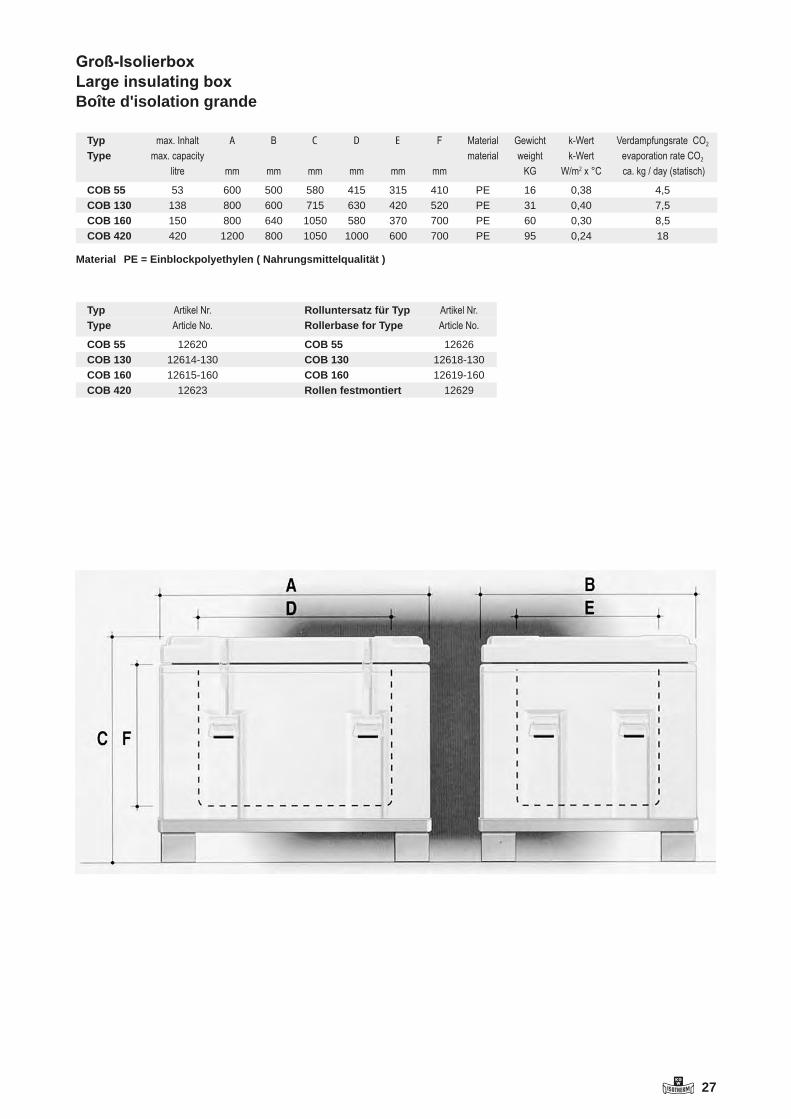
KGW 27
Groß-Isolierbox Large insulating boxBoîte d'isolation grande
Typ max.Inhalt A B C D E F Material Gewicht k-Wert VerdampfungsrateCO2
Type max.capacity material weight k-Wert evaporationrateCO2
litre mm mm mm mm mm mm KG W/m2x°C ca.kg/day(statisch)
COB 55 53 600 500 580 415 315 410 PE 16 0,38 4,5COB 130 138 800 600 715 630 420 520 PE 31 0,40 7,5COB 160 150 800 640 1050 580 370 700 PE 60 0,30 8,5COB 420 420 1200 800 1050 1000 600 700 PE 95 0,24 18
Material PE = Einblockpolyethylen ( Nahrungsmittelqualität )
Typ ArtikelNr. Rolluntersatz für Typ ArtikelNr.Type ArticleNo. Rollerbase for Type ArticleNo.
COB 55 12620 COB 55 12626COB 130 12614-130 COB 130 12618-130COB 160 12615-160 COB 160 12619-160COB 420 12623 Rollen festmontiert 12629

28 KGW
technische Daten siehe rechte Seite / technical data see right page / caractéristiques techniques voir page de droite
Dewargefäße in Kugelform Typ 21 - 24Spherical Dewar flasksRécipients Dewar sphérique
Application - storage and transport of liquid nitrogen (LN2)
Advantages - low evaporation rate- good tipping stability- made of Borosilicatglass 3.3- incl. loose lied lid- incl. handle- deliverable: - fully silvered (standard) - silvered with viewing stripes
Versions AL: aluminium cover, brushedA: glass refill (without cover)
Anwendung - Lagerung und Transport von flüssigem Stickstoff (LN2)
Vorteile - niedrige Verdampfungsrate- hohe Standfestigkeit- aus Borosilicatglas 3.3- inkl. lose aufliegender Isolierdeckel- inkl. Tragebügel - lieferbar: - vollversilbert (Standard) - versilbert mit Sichtstreifen
Ausführungen AL: Aluminium-Umhüllung, gebürstetA: Ersatzglas (ohne Umhüllung)
Application - Stockage et transport d‘azote liquide (LN2)
Avantages - Taux d’ évaporistation bas- Stabilité statique haute- De verre borosilicate 3.3- Incl. couvercle isolant - Incl. étrier de transport- Livrable: - complètement argenté (standard) - argenté avec des rubans visuels
Versions AL: enveloppe d‘aluminium brosséeA: Verre de remplacement (sans enveloppe)
Typ AL / Type AL Typ A / Type A

KGW 29
1. Deckel / lid2. Oberteil / upper part3. Montage-Gummi / mounting rubber4. Dewar / Dewar flask / Typ A5. Schaumstoff-Puffer / cellular-buffer6. Stoßgummi / shock rubber7. Unterteil / bottom part
28
Dewar-Gefäße in Kugelform
Spherical Dewar flasks
Récipients Dewar sphérique
Technische Angaben / Technical Specifications / Caractéristiques techniques
Artikel-Nummern / Article numbers / Référence
L/d = Liter pro Tag / L/d = litre per day
1 Deckel / lid
2 Oberteil / upper part
3 Montage-Gummi / mounting rubber
4 Dewar / Dewar flask
5 Schaumstoff-Puffer / cellular-buffer
6 Stoßgummi / shock rubber
7 Unterteil / bottom part
Typ Artikel Nr. Ersatzglas Artikel Nr.Type Article No. Glass Refill Article No.Types Référence Récipient replacement Référence
21 AL 1291 21 A 127122 AL 1292 22 A 127223 AL 1293 23 A 127324 AL 1294 24 A 1274
50
95
210 65
Dewar-Gefäße in KugelformSpherical Dewar flasksRécipients Dewar sphérique
Typ max.Inhalt A B C D H B1 C1 H1 E1Type max.Content Types Capacitémax.
ca.[L] mm mm mm mm mm mm mm mm mm
21 AL 1 30 50 165 210 70 60 175 150 30022 AL 3 60 85 205 305 110 105 225 210 38023 AL 5 60 85 250 350 110 105 260 275 45024 AL 10 65 95 310 380 85 105 330 310 480
Typ max.Inhalt Gewicht StandzeitLN2 VerdampfungrateLN2Type max.Content Weight HoldingtimeLN2 EvaporationrateLN2Types Capacitémax. poids AutononieLN2 Tauxd‘évaporationLN2
ca.[L] ca.[kg] ca.[d] ca.[L/d]
21 AL 1 1,6 5 0,222 AL 3 3,1 7 0,423 AL 5 4,4 12 0,424 AL 10 6,6 16 0,6
L /d = Liter pro Tag / L/d = litre per day
Artikel-Nummern / Article numbers / Référence
Typ ArtikelNr. Ersatzglas ArtikelNr.Type ArticleNo. Glass Refill ArticleNo.Types Référence Récipient replacement Référence
21 AL 1291 21 A 127122 AL 1292 22 A 127223 AL 1293 23 A 127324 AL 1294 24 A 1274
Typ A

30 KGW
technische Daten siehe rechte Seite / technical data see right page / caractéristiques techniques voir page de droite
Temperierbecher aus Glas Typ TTempering beakers made of glass Typ T-GLBécher thermostatable de verre
Typ T / Type T
Temperierbecher aus Edelstahl Typ TSS-GTempering beakers made of stainless steelBécher thermostatable inox
Application- Maintaining temperature of liquids - The cooling agent heated by a thermaostat is cirulating in the chamber of this double-walled vessel.
Advantages- made of Borosilicatglass 3.3- operating temperature max. 300 °C / Typ T max. 120 °C / Typ T-GL- coolant ram pressure max. 0,5 bar- high thermal resistance- very good chemical resistance- transparency- deliverable:- various special jacket joints- special dimensions
Application
- Maintaining temperature of liquids- The cooling agent heated by a thermostat is cirulating in the chamber of this double-walled vessel.
Advantages
- made of stainless steel- high mechanical breaking strength- stainless- operating temperature max. 200 °C (further temperatu- res by request)- coolant ram pressure max. 0,5 bar
Anwendung
- Temperierung von Flüssigkeiten- Das Temperiermedium wird mit Hilfe eines Thermostaten durch die doppelwandige Hülle gepumpt.
Vorteile
- Aus Edelstahl- hohe mechanische Bruch- festigkeit- nicht rostend- Einsatztemperatur max. 200 °C (weitere Temperaturen auf Anfrage)- Kühlmittelstaudruck max. 0,5 bar
Application- Réglage température de liquides- Le milieu de tempérisation est pompé à travers de l‘enveloppe à double paroi à l‘aide d‘un thermostat.
Avantages- De verre borosilicate 3.3- Température d‘opération max. 300 °C / Typ T max. 120 °C / Typ T-GL- Pression de la retenue d‘agent réfrigérant max. 0,5 bar- thermorésistance haute- Stabilité chimique très bonne- Transparence- Livrable:- connexions manteaux spéciales- dimensions speciales
Anwendung- Temperierung von Flüssigkeiten- Das Temperiermedium wird mit Hilfe eines Thermostaten durch die doppelwandige Hülle gepumpt.
Vorteile- aus Borosilicatglas 3.3- Einsatztemperatur max. 300 °C / Typ T max. 120 °C / Typ T-GL- Kühlmittelstaudruck max. 0,5 bar- hohe Wärmebeständigkeit- sehr gute chemische Beständigkeit- Transparenz- lieferbar:- mit Sonder-Mantelanschlüssen - Sonderabmessungen
Application
- Tempérisation de liquides- Le milieu de tempérisation est pompé à travers de l‘enveloppe à double paroi à l‘aide d‘un thermostat.
Avantages
- D‘acier fin- Résistance à la rupture bonne- antirouille- Température d‘opération max. 200 °C (d‘autres tempéra- tures sur demande)- Pression de retenue d‘agent réfrigérant max. 0,5 bar
Typ T-GL / Type T-GLTyp TSS-G / Type TSS-G

KGW 31
Typ T
Typ T-GL
Typ TSS-G
30
Temperierbecher aus Glas
Tempering beakers made of glass
Bécher thermostatable de verre
Technische Angaben / Technical Specifications / Caractéristiques techniques
Temperierbecher aus Edelstahl
Tempering beakers made of stainless steel
Bécher thermostatable inox
Technische Angaben / Technical Specifications / Caractéristiques techniques
Artikel-Nummern / Article numbers / Référence
Artikel-Nummern / Article numbers / Référence
Weitere Größen und Abmessungen auf Anfrage.
Different sizes and measurements on request.
Typ T
Typ T-GL
Typ TSS
Temperierbecher aus GlasTempering beakers made of glassBécher de temérisation de verre
Technische Angaben / Technical Specifications / Caratéristiques techniques
Typ max.Inhalt A B D E GewichtType max.Content WeightTypes Capacitémax. poids
ca.[ml] mm mm mm mm ca.[kg]
T 250 250 55 70 115 120 0,2T 600 600 77 95 135 150 0,4T 2000 2000 112 135 200 210 0,9
Artikel-Nummern / Article numbers / Référence
Typ ArtikelNr. Typ ArtikelNr. GlasgewindeType ArticleNo. Type ArticleNo. GlassscrewthreadTypes Référence OliveØ Types Référence GL OliveØ
T 250 1351 12 T - GL 250 1355 14 9T 600 1352 12 T - GL 600 1356 14 9T 2000 1353 12 T - GL 2000 1357 18 11
Weitere Größen und Abmessungen auf Anfrage.Different sizes and measurements on request.
Temperierbecher aus EdelstahlTempering beakers made of stainless steelBécher de temérisation de d'ancier fin
Technische Angaben / Technical Specifications / Caratéristiques techniques
Typ max.Inhalt A B D E GewichtType max.Content WeightTypes Capacitémax. poids
ca.[ml] mm mm mm mm ca.[kg]
TSS-G 500 500 65 87 180 203 0,6TSS-G 1000 1000 85 107 206 231 0,9TSS-G 1000 W 1000 100 122 157 177 0,7TSS-G 2000 2000 100 122 285 312 1,3TSS-G 3000 3000 185 200 160 190 1,5TSS-G 6000 6000 185 200 270 300 2,2
Artikel-Nummern / Article numbers / Référence
Typ ArtikelNr.Type ArticleNo.Types Référence OliveØTSS-G 500 2204 9TSS-G 1000 2200 9TSS-G 1000 W 2205 9TSS-G 2000 2201 9TSS-G 3000 2202 9TSS-G 6000 2203 9

32 KGW
technische Daten siehe rechte Seite / technical data see right page / caractéristiques techniques voir page de droite
Typ E Type E
Entsorgungskannen Typ EWaste disposal tanksBrocs d‘élimination
Applications - storage and transport of aggressive waste in laboratory
Advantages - good tipping stability- made of Borosilicatglass 3.3- The glass is resistant against nearly all kinds of chemicals- According DIN12111, 12116, 52322 the glass fulfils the conditions of: - hydrologic class 1 - acid class 1 - alkaline class 2- The glass surface will only be attacked by: - hydrofluoric acid - heated phosphoric acid - alkaline solutions (in high concentration)
Standard equipment - screw lock- overpressure safety device- handle- glass insert- red-coated cover- warning stickers
Anwendung - Lagerung und Transport von aggressiven Abfallstoffen im Labor
Vorteile - hohe Standfestigkeit- aus Borosilicatglas 3.3- Der Glaseinsatz ist resistent gegen fast alle Chemikalien. - Gemäß DIN 12111, 12116, 52322 erfüllt das Glas die Bedingungen der: - Hydrologischen Klasse 1 - Säureklasse 1 - Laugenklasse 2- Die Glasoberfläche wird nur angegriffen von: - Fluss-Säure - erhitzte Phosphorsäure - alkalische Lösungen (hochkonzentriert)
Ausstattung serienmäßig - Schraubverschluss- Überdrucksicherung- Tragebügel- Glaseinsatz- rot beschichtete Umhüllung- Gefahrgut-Aufkleber
Application - Stockage et transport des déchets agressifs dans le laboratoire
Avantages - Stabilité statique haute- De verre borosilicate 3.3 (DURAN)- Le verre est résistant contre presque toutes les substances chimiques.- Selon DIN12111, 12116, 52322 le verre remplit les conditions de: - la classe 1 hydrologique - classe 1 d‘acide - classe 2 de lessive alcaline- La surface de verre n‘est attaquée que par: - l‘acide fluorhydrique - l‘acide phosphorique chauffé - les solutions alcalines (de concentration haute)
Equipement de série - Fermeture à vis- Dispositif protecteur contre surpression- Etrier de transport- Insert de verre- Enveloppe enduite rouge- Bien dangereux-étiquette adhésive

KGW 33
Eine Bedienungsanleitung und weitere Ausführungen finden Sie unter www.kgw-isotherm.de/produkte/kanne.html
A user’s manual and further designs can be found under www.kgw-isotherm.com/produkte/kanne.html
32
Entsorgungskannen
Waste disposal tanks
Brocs d’elimination
Technische Angaben / Technical Specifications / Caractéristiques techniques
Artikel-Nummern / Article numbers / Référence
Typ max. Inhalt A B C D E GewichtType max. Content WeightTypes Capacité max. poids
ca. [ L ] mm mm mm mm mm ca. [ kg ]
E 0 4 87 205 230 325 360 3,5E 1 8 87 250 265 370 420 4,5E 2 15 87 310 330 400 450 6,5
Typ Artikel Nr.Type Article No.Types Référence
E 0 1625E 1 1621E 2 1622
Eine Bedienungsanleitung und weitere Ausführungen finden Sie unter
www.kgw-isotherm.de/produkte/kanne.html
A user’s manual and further designs can be found under
www.kgw-isotherm.com/produkte/kanne.html
EntsorgungskannenWaste disposal tanksBrocs d'elimination
Technische Angaben / Technical Specifications / Caratéristiques techniques
Typ max.Inhalt A B C D E GewichtType max.Content WeightTypes Capacitémax. poids
ca.[L] mm mm mm mm mm ca.[kg]
E 0 4 87 205 230 325 360 3,5E 1 8 87 250 265 370 420 4,5E 2 15 87 310 330 400 450 6,5
Artikel-Nummern / Article numbers /Référence
Typ ArtikelNr.Type ArticleNo.Types Référence
E 0 1625E 1 1621E 2 1622

34 KGW
technische Daten siehe rechte Seite / technical data see right page / caractéristiques techniques voir page de droite
Typ DSS / Type DSS
Dewargefäße aus Edelstahl Typ GSSDewar flasks made of stainless steel Typ DSSRécipients Dewar d‘acier fin
Typ GSS / Type GSS
Application - flexible applications in laboratory- cooling of small samples- storage and transport of :- liquid nitrogen (LN2)- dry ice (CO2) - other coolants- suitable as insulating flask
Advantages - high mechanical breaking strength- easy handling- made of stainless steel- with carrying handle (except type DSS/GSS 500)
Accessories - loose lied insulating plug
Anwendung - vielfältige Anwendung im Labor- Kühlung kleiner Proben- Lagerung und Transport von:- Flüssig-Stickstoff (LN2)- Trockeneis (CO2)- andere Kühlmedien- als Isolierbehälter
Vorteile - hohe mechanische Bruch- festigkeit- einfache Handhabung- aus Edelstahl- mit Tragebügel (außer Typ DSS/GSS 500)
Zubehör - lose aufliegender Isolierstopfen
Application - Application multiple dans le laboratoire- Refroidissement d‘échantillons petits- Stockage et transport:- d‘azote liquide (LN2)- de glace sèche (CO2)- d‘autres milieus réfrigérants- Comme récipient isolant
Avantages - Résistance haute à la rupture mécanique- Maniement simple- D‘acier fin- incl. étrier de support (excepté type DSS/GSS 500)
Accessoires - Bouchon isolant reposant amovible

KGW 35
Dewargefäße aus EdelstahlDewar flasks made of stainless steelRécipients Dewar d' acier fin
Technische Angaben / Technical Specifications / Caratéristiques techniques
Typ max.Inhalt A B D E Gewicht StandzeitLN2 VerdampfungrateLN2Type max.Content Weight HoldingtimeLN2 EvaporationrateLN2Types Capacitémax. poids DurabiltéLN2 Tauxd‘évaporationLN2
ca.[ml] mm mm mm mm ca.[kg] ca.[h] ca.[L/d]
DSS + GSS500 500 65 87 180 203 0,6 12 1,01000 1000 85 107 206 231 0,9 21 0,91000 W 1000 100 122 157 177 0,7 15 1,62000 2000 100 122 285 312 1,3 42 1,13000 3000 185 200 160 190 1,5 22 3,16000 6000 185 200 270 300 2,2 49 2.9
Artikel-Nummern / Article numbers / Référence
Typ ArtikelNr. Stopfen für Typ ArtikelNr. Typ ArtikelNr.Type ArticleNo. Plug for type ArticleNo. Type ArticleNo.Types Référence Bouchon pour type Référence Types Référence
DSS + GSSGSS 500 2304 500 2680 DSS 500 2100GSS 1000 2300 1000 2681 DSS 1000 2101GSS 1000 W 2301 1000 W 2682 DSS 1000 W 2102GSS 2000 2303 2000 2682 DSS 2000 2103GSS 3000 2302 3000 2683 DSS 3000 2104GSS 6000 2305 6000 2683 DSS 6000 2105
LN2 - Verdampfungsrate gemessen mit Stopfen / LN2 – evaporation rate measured with plugL/d = Liter pro Tag / L/d = litre per day

36 KGW
Thermische Isolation von Meßdatenloggern Typ ITETThermal Insulation of Data Measuring LogsThermique isolation des enregistreurs de données de mesure
In refrigeration plants, conveyor, paint or temper ovens, or anywhere where extre-me temperatures are encountered, the exact control of temperature is critical in the quality of the product. Warm handling processes are frequently assisted by tem-perature data devices which control the product through the high and low tempe-rature boundaries. Usually the operating temperature of data logs is in the band of 0° to 60° Celsius. So a thermal insulation is necessary.
ITET is a series of powerful performance hot and cold protection devices developed to provide extreme control in critical situ-ations. It is possible to control the para-meters at the critical spots in the product while the process is running. The sensor is fixed at or in the product and measures the temperature. A remote cable is no longer necessary.
Dans les installations frigorifiques, dans les fours de cuisson à tapis, de trempe ou laquage, le contrôle exact de la tem-pérature est d‘une importance primordiale pour la qualité du produit traité lorsque des températures extrêmes sont atteintes. Les processus de traitement thermique sont souvent surveillés à l‘aide d‘enregistreurs de mesure qui accompagnent le produit lors du passage dans les zones de tem-pératures basses ou élevées. Une isolation thermique de l‘appareil est indispensable puisque l‘écart de températures des enre-gistreurs va généralement de 0°C à 60°C. ITET est une gamme de puissants carters de protection thermique et antigel dévelop-pés pour des applications diverses. Ils per-mettent, combinées avec les enregistreurs de données, de relever les valeurs mesu-rés en cours des processus aux points cri-tiques du produit. Le capteur est fixé sur le produit ou placé à l‘intérieur de celui-ci pour y mesurer l‘évolution de la tempéra-ture. Il n‘éxsiste donc plus aucune manipu-lation encombrante avec des cables.
In Gefrieranlagen, Durchlauf-, Lackier- oder Temperöfen, überall dort wo extreme Temperaturen zum Einsatz kommen, trägt die exakte Temperaturüberwachung maß-geblich zur Qualität der behandelten Pro-dukte bei. Wärmebehandlungs-Prozesse werden häufig mit Hilfe von Meßdatenlog-gern überwacht, welche gemeinsam mit dem Produkt durch die Hoch- bzw. Tief-temperaturzone fahren. Da der Betriebs-temperaturbereich von Meßdatenloggern üblicherweise nur von 0°C bis ca. 60°C reicht, ist eine thermische Isolierung des Gerätes unerläßlich.
ITET ist eine Serie von leistungsstarken Hitze- und Gefrierschutzbehältern, die für eine Vielzahl von Anwendungen entwickelt wurden. Sie ermöglichen es, gemeinsam mit dem Datenlogger, Messwerte während des Prozesses an den kritischen Stellen des Produktes aufzuzeichnen. Der Sensor wird am oder im Produkt fixiert und mißt dort den Temperatur- verlauf. Ein umständ-liches Handtieren mit Schleppkabeln ent-fällt.

KGW 37
Standzeit / Operating time / Durabilité
Typ Standzeit bei Einsatztemperatur [Std. : min] *Type Operating time at surrounding temperature [h : min] *Types Durabilité de la température ambiante [h:min] *
UmgebungstemperaturAmbient temperatureTempérature ambiente
100°C 150°C 200°C
ITET 1 K 8:00 5:00 3:30ITET 1 M 9:00 5:30 4:00ITET 1 W (spritzwasserdicht) 5:45 3:30ITET 1 D (druckfest 4 bar) 8:00 5:00 3:30ITET 2 K 15:45 9:30 6:30ITET 2 G 13:00 8:15 5:45ITET 2 G (Phasenw.) 51:30 23:00 12:00
Umgebungstemperatur -100°C -50°CITET 1 L (Tieftemperatur) 2:30 3:30
Sonderausführungen Special Request Versions spéciales
Falls Sie ein Isolationsproblem haben, bitte fragen Sie bei uns an. Wir werden bemüht sein, Ihnen einen Isolierbehälter anzubie-ten, der Ihren Anforderungen entspricht.Für weitere Informationen stehen wir Ihnen gerne zur Verfügung.(Germany) Fax. 0049 721 / 95897-77
If you have any insulation problem, please send us your requests. We will try to offer an insulation device, that meets your re-quests.
For further information contact us for assis-tance.(Germany) Fax. 0049 721 / 95897-77
Si vous avez un problème d`isolation, veuillez vouz mettre en rapport avec nous. Nous mettrons tout en oeuvre pour vous offrir un carter répondant a vos besoins.Nous restons à votre disposition pour tou-tes autres questions:(Germany) Fax. 0049 721 / 95897-77
Sonderkatalog auf Anfrage oder im Internet unter www.kgw-isotherm.de/downloadsSpecial catalogue on request or on our website www.kgw-isotherm.com/downloads
Technische Änderungen vorbehalten / All rights reserved for technical changes
* Die Standzeit ist die von der Umgebungstemperatur abhängige Einsatzdauer, bei der die Innentemperatur stets im Bereich von 0°C bis 60°C liegt (TStart = 20°C).
* The operating time is the maximal time while the inner temperature is in the range of 0°C to 60°C (TStart=20°C). The operating time depends on the surrounding temperature
* La durabilité (temps où la temperature intérieure reste entre 0° et 60°C) est dépante de la temperature ambiente. (Tdéart= 20°C)
Technische Spezifikationen / Technical data / Spécifications techniques
Typ Maße für DatenloggerDimensions for loggerDim. de l’enregistreurca. [ mm ]
Maße außenouter DimensionsDim. à l’extérieurca. [ mm ]
Gewicht Best.Nr.Type Weight Order No.Types Poids Référence
ca. [ kg ]Ø B H Ø H
ITET 1 K 72 190 120 380 3,5 50011ITET 1 M 145 280 210 530 8,5 50013ITET 1 W 72 190 120 400 3,5 50014ITET 1 D 72 190 155 410 7,0 50015ITET 1 L 72 190 120 380 3,5 50016ITET 2 K 72 190 150 380 4,5 50021ITET 2 G 145 180 240 480 13,5 50022ITET 2 G (Phasenw.) 130 60 190 240 480 16,5 50023

38 KGW
technische Daten siehe rechte Seite / technical data see right page / caractéristiques techniques voir page de droite
Kühlfalle Typ GKFCold trapPiège cryogénique
Typ GKF / Type GKF
Anwendung
- Gasreinigung durch Konden- sation, z.B. in Vakuumanlagen
Vorteile
- aus Borosilicatglas 3.3- hohe chemische Beständigkeit- hohe thermische Beständigkeit- lieferbar: - Typ GKF: Aluminiumfuss (Standard) Rundumschutz - mit Sonderanschlüssen z.B. KF Flansch 16-25
Application
- Nettoyage de gaz par condensation p.e. installations à vide
Avantages
- De verre de borosilicate 3.3 - Résistance chimique haute- Résistance thermique haute- Livrable: - Type GKF: base aluminium (standard) Protection tout autour - avec connexions spéciales p.e. bride KF 16-25
Applications
- gas cleaning by condensation e.g. in vacuum systems
Advantages
- made of Borosilicatglass 3.3- good chemical resistance- good thermal resistance- deliverable: - Type GKF: aluminium foot (Standard), all around protection - with special joints: e.g. KF flange 16-25
Typ Anschlüsse Artikel Nr.GKF NS 29/32 1702GKF-GL25 Glasgewinde
mit Oliven (Da13) 1702-GL25
GKF-KF25 Glasflansch KF-NW25 mit Klammern und NBR-O-Ring
1702-KF25
GKF-S29 Kugelschliffe S29 1702-S29
Type Connections Article No.GKF NS 29/32 1702GKF-GL25 Glass screws
with olives (Da13) 1702-GL25
GKF-KF25 Glass flange KF-NW25 with clamps and NBR-O rings
1702-KF25
GKF-S29 Spherical joints S29 1702-S29

KGW 39
Kühlfalle Typ GKFCold trapPiège cryogénique
Construction Details
- two condensation walls, cooled by liquid nitrogen (LN2 )- integrated Dewar flask- viewing stripes for observing the condensation process - condensate outlet with O - ring sealing- protective cover made of aluminium- coolant capacity : ca. 1100 ml- condensate capacity: ca. 250 ml- joints: - to pump: ground cone NS 29 - to plant: socket NS 29 - insulating lid
Konstruktionsmerkmale
- zwei mit flüssigem Stickstoff (LN2 ) gekühlte Kondensations- Wandungen- integriertes Dewargefäß- Sichtstreifen zur Beobachtung des Kondensationsprozesses- Kondensatablass mit O-Ring- dichtung- Schutzumhüllung aus Aluminium- Kühlmittelinhalt: ca. 1100 ml- Kondensatvolumen : ca. 250 ml- Anschlüsse : - Pumpseitig: Kernschliff NS 29 - Anlagenseitig: Hülse NS 29 - Isolierdeckel
Caractéristiques constructives
- Deux parois de condensation réfrigérées avec de l’azote liquide (LN2)- Récipient Dewar intégré- Rubans visuels pour l’obser- vation du processus de conden- sation- Décharge de condensat avec anneau torique d’étanchéité- Enveloppe de protection d’aluminium- Contenu d’agent réfrigérant: 1100 ml- Volume de condensat: 250 ml- Connexions : - de côté de pompe: rodage mâle NS29 - de côté d’installation: enve- loppe NS29 - Couvercle isolant
Kühlfallenkatalog auf Anfrage oder im Internet unter www.kgw-isotherm.de/downloadsCold trap catalogue on request or on our website www.kgw-isotherm.com/downloads
38
Kühlfalle Typ GKF
Cold trap
Piège cryogénique
Construction Details
- two condensation walls,
cooled by liquid nitrogen (LN2 )
- integrated Dewar flask
- viewing stripes for observing the
condensation process
- condensate outlet with O - ring sealing
- protective cover made of aluminium
- coolant capacity : ca. 1100 ml
- condensate capacity: ca. 250 ml
- joints:
to pump: ground cone NS 29
to plant: socket NS 29
- insulating lid
Konstruktionsmerkmale
- zwei mit fl. Stickstoff (LN2 ) gekühlte
Kondensations-Wandungen
- integriertes Dewargefäß
- Sichtstreifen zur Beobachtung
des Kondensationsprozesses
- Kondensatablass mit O-Ringdichtung
- Schutzumhüllung aus Aluminium
- Kühlmittelinhalt: ca. 1100 ml
- Kondensatvolumen : ca. 250 ml
- Anschlüsse :
- Pumpseitig: Kernschliff NS 29
- Anlagenseitig: Hülse NS 29
- Isolierdeckel
Caractéristiques constructives
- Deux parois de condensation
réfrigérées avec de l’azote liquide (LN2)
- Récipient Dewar intégré
- Rubans visuels pour l’observation
du processus de condensation
- Décharge de condensat avec anneau
torique d’étanchéité
- Enveloppe de protection d’aluminium
- Contenu d’agent réfrigérant: 1100 ml
- Volume de condensat: 250 ml
- Connexions :
de côté de pompe:rodage mâle NS29
de côté d’installation: enveloppe NS29
- Couvercle isolant
Kühlfallenkatalog auf Anfrage oder im Internet unter www.kgw-isotherm.de/downloads
Cold trap catalogue on request or on our website www.kgw-isotherm.com/downloads

40 KGW
technische Daten siehe rechte Seite / technical data see right page / caractéristiques techniques voir page de droite
Kühlfinger Cold trap Doigt réfrigérant
Typ KF 29-K Typ KF 29-OK Typ KF 29-GL Typ KF 29-GL-AType KF 29-K Type KF 29-OK Type KF 29-GL Type KF 29-GL-A
Kühlfallen: Funktion Aufbau und WirkungsweiseKühlfallen werden zum Auskondensieren von Feuch-tigkeit oder Lösungsmittel in Verbindung mit Vaku-umpumpen eingesetzt. Hierbei kann die Kühlfalle un-terschiedliche Aufgaben wahrnehmen. Die gängigste Anwendung ist das Auskondensieren von Feuchtigkeit oder Lösungsmittel bei Drehschieber - Vakuumpumpen oder Hochvakuumanlagen mit Öldiffusions - oder Tur-bomolekularpumpen. Hierfür werden normalerweise gängige Kühlmittel wie flüssiger Stickstoff (LN2) oder Trockeneis (CO2) mit Aceton eingesetzt.
Cold traps: construction, operation and principlesCold traps are used in conjunction with vacuum pumps to collect condensation produced from humidity or sol-vents and these cold traps can be used for many diffe-rent tasks. The most common application is collecting condensation produced from humidity or solvents from rotating discs, vacuum pumps or high vacuum systems that use‘s oil diffusion or turbo-molecular pumps. In this case a common coolant such as liquid nitrogen (LN2) or dry-ice (CO2) with acetone is normally used.
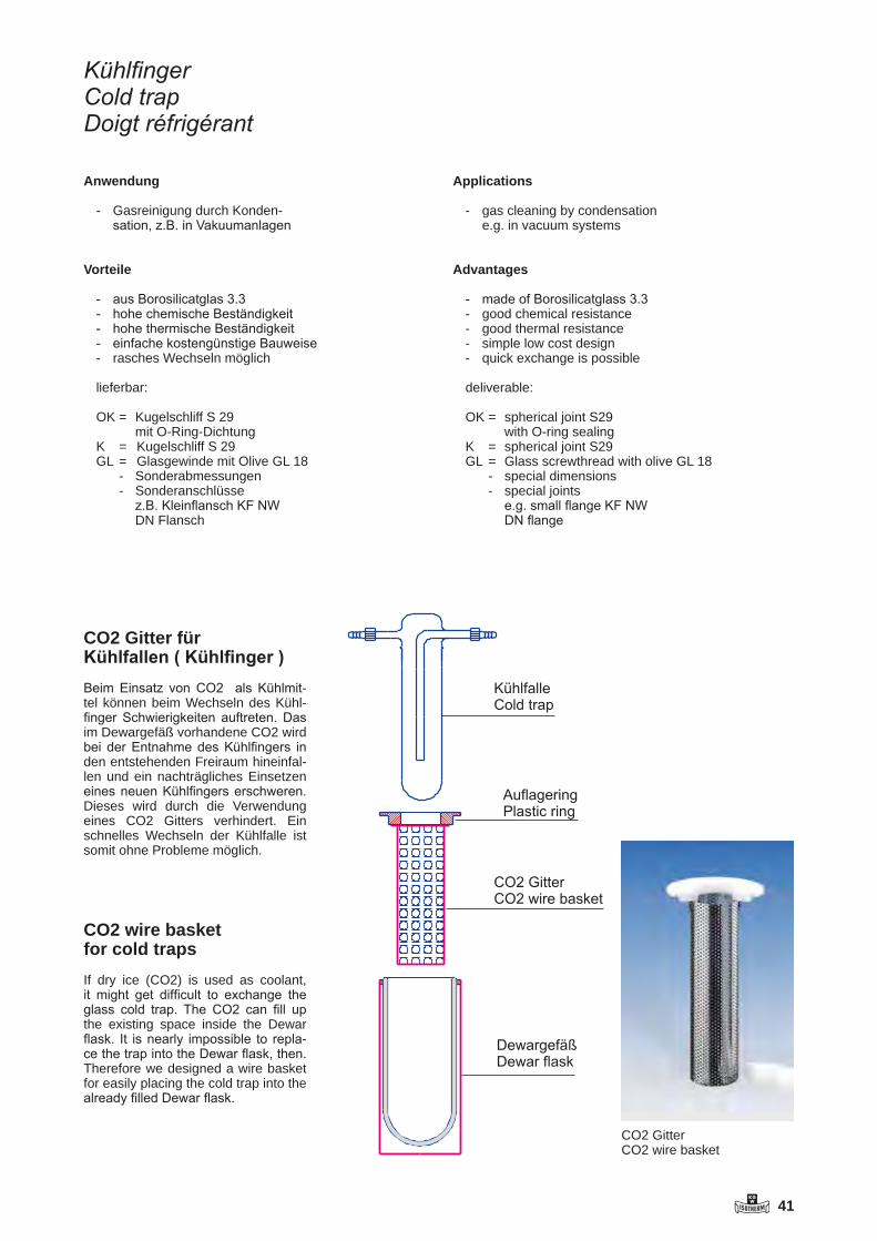
KGW 41
Applications
- gas cleaning by condensation e.g. in vacuum systems
Advantages
- made of Borosilicatglass 3.3- good chemical resistance- good thermal resistance- simple low cost design- quick exchange is possible
deliverable:
OK = spherical joint S29 with O-ring sealingK = spherical joint S29 GL = Glass screwthread with olive GL 18 - special dimensions - special joints e.g. small flange KF NW DN flange
Anwendung
- Gasreinigung durch Konden- sation, z.B. in Vakuumanlagen
Vorteile
- aus Borosilicatglas 3.3- hohe chemische Beständigkeit- hohe thermische Beständigkeit- einfache kostengünstige Bauweise- rasches Wechseln möglich
lieferbar: OK = Kugelschliff S 29 mit O-Ring-DichtungK = Kugelschliff S 29 GL = Glasgewinde mit Olive GL 18 - Sonderabmessungen - Sonderanschlüsse z.B. Kleinflansch KF NW DN Flansch
KühlfingerCold trapDoigt réfrigérant
CO2 Gitter für Kühlfallen ( Kühlfinger )Beim Einsatz von CO2 als Kühlmit-tel können beim Wechseln des Kühl-finger Schwierigkeiten auftreten. Das im Dewargefäß vorhandene CO2 wird bei der Entnahme des Kühlfingers in den entstehenden Freiraum hineinfal-len und ein nachträgliches Einsetzen eines neuen Kühlfingers erschweren. Dieses wird durch die Verwendung eines CO2 Gitters verhindert. Ein schnelles Wechseln der Kühlfalle ist somit ohne Probleme möglich.
CO2 wire basket for cold trapsIf dry ice (CO2) is used as coolant, it might get difficult to exchange the glass cold trap. The CO2 can fill up the existing space inside the Dewar flask. It is nearly impossible to repla-ce the trap into the Dewar flask, then. Therefore we designed a wire basket for easily placing the cold trap into the already filled Dewar flask.
KühlfalleCold trap
AuflageringPlastic ring
CO2 GitterCO2 wire basket
DewargefäßDewar flask
CO2 GitterCO2 wire basket

42 KGW
Kühlfallen kurze VersionCold traps short version
Kühlfallen kurze Version (Kühlfinger)Einfache Kühlfallen, auch Kühlfinger genannt, sind für Standard-Anwendungen in Verbindung mit Va-kuumpumpen. Hierbei werden Feuchtigkeit oder Lö-sungsmittel im Bereich der chemischen Anwendung auskondensiert. Die Kühlfalle wird hierbei zum Schutz der Vakuumpumpe eingesetzt. Die Besonderheit bei diesem Aufbau ist, dass der Anwender kein Stativ zum Halten der Kühlfalle benötigt. Die Kühlfalle besitzt ei-nen Wulst, mit dem sie in den Auflagering des Dewar-gefäßes eingehängt wird. Ein schnelles Wechseln der Kühlfalle ist somit ohne Probleme möglich.
Cold Traps short version (cold finger condenser)Simple cold traps, which are also known as cold fin-ger condensers, are used in standard applications in conjunction with vacuum pumps and the condensati-on is forced out of the humidity or solvents used in the chemical applications. The cold trap is used to protect the vacuum pump in this case and the speciality of this type of construction is that the user does not need to use a stand to hold the cold trap. The cold trap has a rim, which is hung inside the Dewar-flask‘s support ring. The cold trap can be changed very quickly without any problems arising.
50
205
160
50
205
160
50
205
160
Kühlfinger komplett mit Kondensat Kühlmittel Art.Nr.
Dewar und Kunststoffring theoret.Vol. theoret.Vol. Art.No.
Cold trap complete with Condensate Coolant
Dewar and plastic ring theoret.cap. theoret.cap.
Typ / Type KF 29-K 150 ml 1000 ml 1731
Typ / Type KF 29-OK 150 ml 1000 ml 1735
Typ / Type KF 29-GL 150 ml 1000 ml 1740
Zubehör / accessorie Art.No.
CO2 GitterCO2 wire basket 17570
Kühlfalle komplett Typ KF 29-GLCold trap complete Type KF 29-GL
Kühlfalle zu KF 29-KCold trap for KF 29-K
theoret.Vol. = Theoretisches Volumentheoret cap. = theoretical capacity
Ersatzteile auf Anfrage oder im Kühlfallenkatalog unter www.kgw-isotherm.deAccessories on request or on our Homepage under www.kgw-isotherm.de
Kühlfalle zu KF 29-OKCold trap for KF 29-OK
Kühlfalle zu KF 29-GLCold trap for KF 29-GL

KGW 43
Kühlfallen kurze Version mit AusgussöffnungCold traps short version with a spout
Kühlfallen kurze Version mit AusgussöffnungEine erweiterte Ausführung sind Kühlfallen mit einer Ausgussöffnung. Diese Kühlfallen sind wie die Stan-dard Kühlfallen aufgebaut und besitzen ein Glasgewin-de GL 32 mit Verschlusskappe als Ausgussöffnung. Mit dieser Ausgussöffnung lässt sich das Kondensat ohne Schwierigkeiten aus den Kühlfallen entnehmen und die Kühlfallen sind leicht und einfach zu reinigen.
Cold traps short version with a spoutAn upgraded version is a cold trap with an outlet. These cold traps are constructed in the same way as standard cold traps but have a GL 32 glass thread together with a screw-on cap, which is the actual spout. With the help of this spout the condensate can easily be poured out of the cold trap. Therefore the cold trap is easily to clean.
50
205
160
50
205
160
50
160
205
Kühlfinger komplett mit Kondensat Kühlmittel Art.Nr.
Dewar und Kunststoffring theoret.Vol. theoret.Vol. Art.No.
Cold trap complete with Condensate Coolant
Dewar and plastic ring theoret.cap. theoret.cap.
Typ / Type KF 29-K-A 150 ml 1000 ml 17370
Typ / Type KF 29-OK-A 150 ml 1000 ml 17371
Typ / Type KF 29-GL-A 150 ml 1000 ml 17372
Zubehör / accessorie Art.No.
CO2 GitterCO2 wire basket 17570
Kühlfalle komplett Typ KF 29-GL-ACold trap complete Type KF 29-GL-A
Kühlfalle zu KF 29-K-ACold trap for KF 29-K-A
theoret.Vol. = Theoretisches Volumentheoret cap. = theoretical capacity
Ersatzteile auf Anfrage oder im Kühlfallenkatalog unter www.kgw-isotherm.deAccessories on request or on our Homepage under www.kgw-isotherm.de
Kühlfalle zu KF 29-OK-ACold trap for KF 29-OK-A
Kühlfalle zu KF 29-GL-ACold trap for KF 29-GL-A

44 KGW
Kühlfallen lange VersionCold traps long version
Kühlfallen lange Version (Kühlfinger)Einfache Kühlfallen, auch Kühlfinger genannt, sind für Standard-Anwendungen in Verbindung mit Va-kuumpumpen. Hierbei werden Feuchtigkeit oder Lö-sungsmittel im Bereich der chemischen Anwendung auskondensiert. Die Kühlfalle wird hierbei zum Schutz der Vakuumpumpe eingesetzt. Die Besonderheit bei diesem Aufbau ist, dass der Anwender kein Stativ zum Halten der Kühlfalle benötigt. Die Kühlfalle besitzt ei-nen Wulst, mit dem sie in den Auflagering des Dewar-gefäßes eingehängt wird. Ein schnelles Wechseln der Kühlfalle ist somit ohne Probleme möglich.
Cold Traps long version (cold finger condenser)Simple cold traps, which are also known as cold fin-ger condensers, are used in standard applications in conjunction with vacuum pumps and the condensati-on is forced out of the humidity or solvents used in the chemical applications. The cold trap is used to protect the vacuum pump in this case and the speciality of this type of construction is that the user does not need to use a stand to hold the cold trap. The cold trap has a rim, which is hung inside the Dewar-flask‘s support ring. The cold trap can be changed very quickly without any problems arising.
50
260
180
50
260
180
50
180
260
Kühlfinger komplett mit Kondensat Kühlmittel Art.Nr.
Dewar und Kunststoffring theoret.Vol. theoret.Vol. Art.No.
Cold trap complete with Condensate Coolant
Dewar and plastic ring theoret.cap. theoret.cap.
Typ / Type KFL 29-K 250 ml 2000 ml 17360
Typ / Type KFL 29-OK 250 ml 2000 ml 17361
Typ / Type KFL 29-GL 250 ml 2000 ml 17362
Zubehör / accessorie Art.No.
CO2 GitterCO2 wire basket 17571
Kühlfalle komplett Typ KF 29-GLCold trap complete Type KF 29-GL
Kühlfalle zu KFL 29-KCold trap for KFL 29-K
theoret.Vol. = Theoretisches Volumentheoret cap. = theoretical capacity
Ersatzteile auf Anfrage oder im Kühlfallenkatalog unter www.kgw-isotherm.deAccessories on request or on our Homepage under www.kgw-isotherm.de
Kühlfalle zu KFL 29-OKCold trap for KFL 29-OK
Kühlfalle zu KFL 29-GLCold trap for KFL 29-GL

KGW 45
Kühlfallen lange Version mit AusgussöffnungCold traps long version with a spout
Kühlfallen lange Version mit AusgussöffnungEine erweiterte Ausführung sind Kühlfallen mit einer Ausgussöffnung. Diese Kühlfallen sind wie die Stan-dard Kühlfallen aufgebaut und besitzen ein Glasgewin-de GL 32 mit Verschlusskappe als Ausgussöffnung. Mit dieser Ausgussöffnung lässt sich das Kondensat ohne Schwierigkeiten aus den Kühlfallen entnehmen und die Kühlfallen sind leicht und einfach zu reinigen.
Cold traps long version with a spoutAn upgraded version is a cold trap with an outlet. These cold traps are constructed in the same way as standard cold traps but have a GL 32 glass thread together with a screw-on cap, which is the actual spout. With the help of this spout the condensate can easily be poured out of the cold trap. Therefore the cold trap is easily to clean.
50
180
260
50
260
180
50
260
180
Kühlfinger komplett mit Kondensat Kühlmittel Art.Nr.
Dewar und Kunststoffring theoret.Vol. theoret.Vol. Art.No.
Cold trap complete with Condensate Coolant
Dewar and plastic ring theoret.cap. theoret.cap.
Typ / Type KFL 29-K 250 ml 2000 ml 17385
Typ / Type KFL 29-OK 250 ml 2000 ml 17386
Typ / Type KFL 29-GL 250 ml 2000 ml 17387
Zubehör / accessorie Art.No.
CO2 GitterCO2 wire basket 17571
Kühlfalle komplett Typ KF 29-GL-ACold trap complete Type KF 29-GL-A
Kühlfalle zu KFL 29-K-ACold trap for KFL 29-K-A
theoret.Vol. = Theoretisches Volumentheoret cap. = theoretical capacity
Ersatzteile auf Anfrage oder im Kühlfallenkatalog unter www.kgw-isotherm.deAccessories on request or on our Homepage under www.kgw-isotherm.de
Kühlfalle zu KFL 29-OK-ACold trap for KFL 29-OK-A
Kühlfalle zu KFL 29-GL-ACold trap for KFL 29-GL-A

46 KGW
Kühlfallen (Kühlfinger mit KF NW Vakuumflanschen)Cold traps (cold finger condenser with KF NW flange)
Kühlfallen ( Kühlfinger mit KF NW Vakuumflanschen ) Einfache Kühlfallen, auch Kühlfinger genannt, sind für Standard-Anwendungen in Verbindung mit Va-kuumpumpen. Hierbei werden Feuchtigkeit oder Lö-sungsmittel im Bereich der chemischen Anwendung auskondensiert. Die Kühlfalle wird hierbei zum Schutz der Vakuumpumpe eingesetzt. Die Besonderheit bei diesem Aufbau ist, dass der Anwender kein Stativ zum Halten der Kühlfalle benötigt. Die Kühlfalle besitzt ei-nen Wulst, mit dem sie in den Auflagering des Dewar-gefäßes eingehängt wird. Ein schnelles Wechseln der Kühlfalle ist somit ohne Probleme möglich. Die Vaku-umkleinflansche aus Glas ermöglichen das Anschlie-ßen an Pumpstände mit metallischen Vakuum-Klein-flanschen.
Cold Traps ( cold finger condenser with KF NW flange)Simple cold traps, which are also known as cold finger condensers, are used in standard applications in con-junction with vacuum pumps and the condensation is forced out of the humidity or solvents used in the che-mical applications. The cold trap is used to protect the vacuum pump in this case and the speciality of this type of construction is that the user does not need to use a stand to hold the cold trap. The cold trap has a rim, which is hung inside the Dewar flask‘s support ring. The cold trap can be changed very quickly without any pro-blems arising. With glass vacuum flanges you are able to connect this cold trap directly to the metal flanges of a high vacuum pump.
Kühlfalle für KF 29-NW 16Cold trap for KF 29-NW 16
theoret.Vol. = Theoretisches Volumen theoret cap. = theoretical capacity
Ersatzteile auf Anfrage oder im Kühlfallenkatalog unter www.kgw-isotherm.deAccessories on request or on our Homepage under www.kgw-isotherm.de
Kühlfalle für KF 29-NW 16-ACold trap for KF 29-NW 16-A
205
160
50
205
160
GL 32
50
Rändel-Mutterknurled nut
Pertinax-PlattePertinax-plate
Pertinax-Platte mitGewindestäbe
Pertinax-plate withthreaded spindle
Zentrierring mit O-Ringouter centering ringwith O-ringPerbunan
Rändel-Mutterknurled nut
Pertinax-PlattePertinax-plate
Pertinax-Platte mitGewindestäbe
Pertinax-plate withthreaded spindle
Zentrierring mit O-Ringouter centering ringwith O-ringPerbunan
Metall Flansch NW 10/16metal flange NW 10/16
Glasflansch NW 10/16glass flange NW 10/16
Aufbau der KF NWVerbindungen
Configuration of theNW connection
Kühlfallen komplett Kondensat Kühlmittel Dewar Kühlfallen Best.Nr.
Typ theoret.Vol. theoret.Vol. Typ Anschlüsse
Cold traps complete Condensate Coolant Dewar Coldtrap Art.No.
Type theoret.cap. theoret.cap. Type joints
Typ KF 29-NW 16 150 ml 1000 ml 12 C KF NW 16 1731-NW16
Typ KF 29-NW 25 150 ml 1000 ml 12 C KF NW 25 1731-NW25
Typ KF 29-NW 16-A 150 ml 1000 ml 12 C KF NW 16 17370-NW16
Typ KF 29-NW 25-A 150 ml 1000 ml 12 C KF NW 25 17370-NW25
AnschlussartenNW 16 = Vakuumkleinflansch NW 16NW 25 = Vakuumkleinflansch NW 25 - A = Kühlfalle mit Auslauf GL 32
Conection typesNW 16 = Vacuum flange NW 16NW 25 = Vacuum flange NW 25A = cold trap fitted with a spout GL 32

KGW 47
Kühlfallen lange Version (Kühlfinger mit KF NW Vakuumflanschen)Cold traps long version (cold finger condenser with KF NW flange)
Kühlfallen lange Version ( Kühlfinger mit KF NW Vakuumflanschen ) Einfache Kühlfallen, auch Kühlfinger genannt, sind für Standard-Anwendungen in Verbindung mit Va-kuumpumpen. Hierbei werden Feuchtigkeit oder Lö-sungsmittel im Bereich der chemischen Anwendung auskondensiert. Die Kühlfalle wird hierbei zum Schutz der Vakuumpumpe eingesetzt. Die Besonderheit bei diesem Aufbau ist, dass der Anwender kein Stativ zum Halten der Kühlfalle benötigt. Die Kühlfalle besitzt ei-nen Wulst, mit dem sie in den Auflagering des Dewar-gefäßes eingehängt wird. Ein schnelles Wechseln der Kühlfalle ist somit ohne Probleme möglich. Die Vaku-umkleinflansche aus Glas ermöglichen das Anschlie-ßen an Pumpstände mit metallischen Vakuum-Klein-flanschen.
Cold Traps long version ( cold finger condenser with KF NW flange)Simple cold traps, which are also known as cold finger condensers, are used in standard applications in con-junction with vacuum pumps and the condensation is forced out of the humidity or solvents used in the che-mical applications. The cold trap is used to protect the vacuum pump in this case and the speciality of this type of construction is that the user does not need to use a stand to hold the cold trap. The cold trap has a rim, which is hung inside the Dewar flask‘s support ring. The cold trap can be changed very quickly without any pro-blems arising. With glass vacuum flanges you are able to connect this cold trap directly to the metal flanges of a high vacuum pump.
Kühlfalle komplett Typ KFL 29-NW 16Cold trap compl. Type KFL 29-NW 16
Kühlfalle für KFL 29-NW 16Cold trap for KFL 29-NW 16
Kühlfalle für KFL 29-NW 16-ACold trap for KFL 29-NW 16-A
260
180
50
260
180
GL 32
50
Rändel-Mutterknurled nut
Pertinax-PlattePertinax-plate
Pertinax-Platte mitGewindestäbe
Pertinax-plate withthreaded spindle
Zentrierring mit O-Ringouter centering ringwith O-ringPerbunan
Rändel-Mutterknurled nut
Pertinax-PlattePertinax-plate
Pertinax-Platte mitGewindestäbe
Pertinax-plate withthreaded spindle
Zentrierring mit O-Ringouter centering ringwith O-ringPerbunan
Metall Flansch NW 10/16metal flange NW 10/16
Glasflansch NW 10/16glass flange NW 10/16
Aufbau der KF NWVerbindungen
Configuration of theNW connection
theoret.Vol. = Theoretisches Volumen theoret cap. = theoretical capacity
Ersatzteile auf Anfrage oder im Kühlfallenkatalog unter www.kgw-isotherm.deAccessories on request or on our Homepage under www.kgw-isotherm.de
Kühlfallen komplett Kondensat Kühlmittel Dewar Kühlfallen Best.Nr.
Typ theoret.Vol. theoret.Vol. Typ Anschlüsse
Cold traps complete Condensate Coolant Dewar Coldtrap Art.No.
Type theoret.cap. theoret.cap. Type joints
Typ KFL 29-NW 16 250 ml 2000 ml 18 C KF NW 16 17360-NW16
Typ KFL 29-NW 25 250 ml 2000 ml 18 C KF NW 25 17360-NW25
Typ KFL 29-NW 16-A 250 ml 2000 ml 18 C KF NW 16 17380-NW16
Typ KFL 29-NW 25-A 250 ml 2000 ml 18 C KF NW 25 17380-NW25

48 KGW
Kühlfallen, zweiteilig, in kurzer und langer VersionCold traps, two sections, in short and long version
Kühlfalle, zweiteilig, in kurzer und langer VersionEine besondere Ausführung sind zweiteilige Kühlfallen in der Standard- und in der langen Version, mit einen NS 45/40 Kegelschliff als Verbindungsteil. Bei diesen Kühlfallen kann der Kondensatraum vom Oberteil der Kühlfallen getrennt werden. Somit ist die Entnahme des Kondensates und das Reinigen der Kühlfallen sehr leicht durchzuführen. Diese Ausführung eignet sich auch für einen festen Einbau der Kühlfallen in eine Apparatur, da zur Kondensat-leerung nur das Unterteil von der Kühlfallen abgenommen werden muss. Das Verbindungsteil NS45/40 wird mit einer Federstahl-klemme gesichert und ist im Lieferumfang enthalten.
Cold traps, two sections, in short and long versionsThe two section cold trap is a special design availab-le in both, standard and long version. It has a conical ground joint NS 45/40 as connection part. The conden-sation area can be separated from the upper section of cold trap. Therefore it is easy to pour out the condensa-te and to clean the whole cold trap. This version is also perfect, if the cold trap is permanently installed in an apparatus, since the upper section can stay, while the lower section is taken off for cleaning. The connection part NS 45/40 is secured by a spring clamp out of steel that is included in the scope of delivery.
T
NS 45
50
T
50
NS 45NS 45
50
T
Kühlfalle komplettType KF 29-GL-Z Cold trap complete Type KF 29-GL-Z
Kühlfalle für KF 29-ZCold trap for KF 29-Z
theoret.Vol. = Theoretisches Volumentheoret cap. = theoretical capacity
Ersatzteile auf Anfrage oder im Kühlfallenkatalog unter www.kgw-isotherm.deAccessories on request or on our Homepage under www.kgw-isotherm.de
Kühlfalle für KF 29 O-ZCold trap for KF 29 OK
Kühlfalle für KF 29-GL-ZCold trap for KF 29-GL-Z
Kühlfinger kurze Version, zweiteilig Kondensat Kühlmittel
mit Dewar und Kunststoffring Länge T theoret.Vol. theoret.Vol. Art.Nr.
Cold trape in short version, two section Condensate Coolant
with Dewar and plastic ring lenght T theoret.cap. theoret.cap. Art.No.
Typ KF 29-K-Z 200 150 ml 1000 ml 17400
Typ KF 29-OK-Z 200 150 ml 1000 ml 17401
Typ KF 29-GL-Z 200 150 ml 1000 ml 17402
Kühlfinger langer Version, zweiteilig Kondensat Kühlmittel
mit Dewar und Kunststoffring Länge T Volumen Volumen Art.Nr.
Cold trape in long version, two section Condensate Coolant
with Dewar and plastic ring lenght T theoret.cap. theoret.cap. Art.No.
Typ KFL 29-K-Z 260 250 ml 2000 ml 17410
Typ KFL 29-OK-Z 260 250 ml 2000 ml 17411
Typ KFL 29-GL-Z 260 250 ml 2000 ml 17412

KGW 49
Große Kühlfallen in Sondergrößen nach KundenwunschBigger cold traps, produced to customer´s specifications
Ersatzteile auf Anfrage oder im Kühlfallenkatalog unter www.kgw-isotherm.deAccessories on request or on our Homepage under www.kgw-isotherm.de
100
200
Dewar Type 44X
300
Kühlfalle KS-10-K25-44Xcold trap KS-10-K25-44X
Aluminium CALSchutzumhüllung
aluminium casing CAL
Auflageringplastic ring
KF NW 25 mit Pertinax Klammer und O-Ring
KF NW 25 with Pertinax clamp and O-ring
50
0
45
0
80
158
GL25 mit OliveGL25 with olive
Dewar Type 41X (CAL)
Kühlfalle KS-8-G25-41Xcold trap KS-8-G25-41X
260
13
Aluminium CALSchutzumhüllung
aluminium casing CAL
Auflageringplastic ring
35
0
40
0
Sonderkühlfalle Typ KFS-8-G25-41X
Technische Daten
KühlfalleKondensatmenge, theoretisch 1,2 LiterKondensatmenge, realistisch 0,6 Liter
DewarLN2 Kühlmittel max. 4,6 Liter
Custom-made glass cold trap,Type KFS-8-G25-41X
Technical data
Cold trapcalculated condensate capacity: 1,2 litrerealistic condensate capacity: 0,6 litre
Dewar flaskmaximum capacity of coolant: 4,6 litres
Sonderkühlfalle Typ KFS-10-K25-44X
Technische Daten
KühlfalleKondensatmenge, theoretisch 2,2 LiterKondensatmenge, realistisch 1,1 Liter
DewarLn2 Kühlmittel max. 8,1 Liter
Custom-made glass cold trapType KFS-10-K25-44X
Technical data
Cold trapcalculated condensate capacity: 2,2 litresrealistic condensate capacity: 1,1 litre
Dewar flaskmaximum capacity of coolant: 8,1 litres

50 KGW
Kühlfalle aus V2A Typ KF 54 V mit DewargefäßCold trap made of stainless steel Type KF 54 V with Dewar flask
KühlfalleCold trap
AuflageringPlastic ring
DewargefäßDewar flask
Kühlfalle / Cold trapTyp /TypeKF 54 V-K16-Z-DSS2000
Kühlfalle / Cold trapTyp / TypeKF 54 V-K16-Z-18C
Kühlfalle / Cold trapTyp / TypeS 54 V-K16-Z
Technische Daten
Dewargefäß Typ 18 C oderDewargefäß Typ DSS 2000Edelstahl / Chromnickelstahl
Auflagering = PE, weiß, zweiteilig
Technische Daten der KühlfalleAnschlüsse der Kühlfalle = KF NW 16 Kühlfalle zweiteilig KF NW 50
Kühlfalle Material V2A V2A / 1.4301
Druckbereich der Kühlfalle Vakuum bis 10* mbarDruck bis 3 bar Überdruck
Technical Data
Dewar flask Type 18 C orDewar flask Type DSS 2000stainless steel
Plastic ring = PE, white, two-parted
Description of the cold trapconnectors of the cold trap = KF NW 16 cold trap two-parted with KF NW 50
Cold trap material V2A / 1.4301
Pressure range of the cold trapup to 3 bar excess pressure vacuum up to 10* mbar
Ersatzteile auf Anfrage oder im Kühlfallenkatalog unter www.kgw-isotherm.deAccessories on request or on our Homepage under www.kgw-isotherm.de

KGW 51
Große Kühlfallen in Sondergrößen nach KundenwunschBigger cold traps, produced to customer´s specifications
KühlfalleCold trap
AuflageringPlastic ring
CO2-GitterCO2 wire basket
DewargefäßDewar flask
Ersatzteile auf Anfrage oder im Kühlfallenkatalog unter www.kgw-isotherm.deAccessories on request or on our Homepage under www.kgw-isotherm.de
Dewar mit CO2-Gitter und Auflagering
Dewar flask with Co2 wire basket and plastic ring
Kühlfallen komplett Kondensat Kühlmittel Dewar Kühlfallen Best.Nr.
Volumen Volumen Typ Anschlüsse
Cold traps complete Condensate Coolant Dewar Coldtrap Art.No.
capacity capacity Type joints
Typ KF 54V-K16-Z-18C 200ml 1,6Liter 18 C KFNW16 17110
Typ KF 54V-K16-Z-DSS2000 200ml 1,2Liter DSS 2000 KFNW16 17111
Kühlfallen komplett mit CO2 Gitter Kondensat Kühlmittel Dewar Kühlfallen Best.Nr.
Volumen Volumen Typ Anschlüsse
Cold traps complete with CO2 wire basket Condensate Coolant Dewar Coldtrap Art.No.
capacity capacity Type joints
Typ KF 54V-K16-Z-18C-CO2 200ml 1,6Liter 18 C KFNW16 17130
Typ KF 54V-K16-Z-DSS2000-CO2 200ml 1,2Liter DSS 2000 KFNW16 17131
Kühlfalle zweiteilig
Cold trap two parted
CO2-Gitter mit Auflagering(zweiteilig)
Co2 wire basket with plastic ring (two parted)

52 KGW
technische Daten siehe rechte Seite / technical data see right page / caractéristiques techniques voir page de droite
Chemiepumpstand mit zwei Kühlfallen Typ CPChemistry pump device with two cold traps
Applications
- flexible applications in laboratory e.g. for: - drying processes - condensation processes - vacuum technology - gas cleaning
Advantages
- compact design- easy handling- suitable for aggressive mediums- glass components in Borosilicat 3.3- O-ring sealed spherical joints incl. fork clamps- mobile rack- PE table board - parallel operation with 2 cold traps. On failure of one cold trap the other cold trap keeps on working- alternate operation with 1 cold trap. The cold trap in use is chosen by the valve adjustment
Article numberType with manometer: CP 1Article No.: 1707
Type without manometer: CP 2Article No.: 1708
Anwendung
- vielfältige Anwendung im Labor z.B. bei: - Trocknungsprozessen - Kondensationsprozessen - Vakuumtechnik - Gasreinigung
Vorteile
- kompakte Bauweise- einfache Handhabung- geeignet für aggressive Medien- Glasbauteile aus Borosilicatglas 3.3- O-Ring gedichtete Kugelschiffe inkl. Gabel-Klammern - fahrbares Gestell- Tischplatte aus PE- paralleler Betrieb über 2 Kühlfallen. Bei Ausfall einer Kühlfalle arbeitet die andere Kühlfalle weiter.- wechselseitiger Betrieb (1 Kühlfalle). Durch die Ventilein- stellung wird die eingesetzte Kühlfalle ausgewählt.
ArtikelnummerTyp mit Manometer: CP 1Artikel Nr.: 1707
Typ ohne Manometer: CP 2Artikel Nr.: 1708
Lieferumfang ohne Vakuumpumpe / Delivery without vacuum pumpTechnische Änderungen vorbehalten / All rights reserved for technical changes
41
Chemiepumpstand mit zwei Kühlfallen Typ CP
Chemistry pump device with two cold traps
Etat de pompes de chimie avec deux doigts réfrigérant
Applications
- flexible applications in laboratory
e.g. for - drying processes
- condensation processes
- vacuum technology
- gas cleaning
Advantages
- compact design
- easy handling
- suitable for aggressive mediums
- glass components in Borosilicat 3.3
- O-Ring sealed spherical joints
incl. fork clamps
- frame work on wheels
- table board made of PE
- parallel operation with 2 cold traps
On failure of one cold trap the
other cold trap keeps on working
- alternate operation with 1 cold trap
The cold trap in use is chosen
by the valve adjustment
Article number
Type with pressure gauge: CP 1
Article No.: 1707
Type without pressure gauge: CP 2
Article No.: 1708
technical data see back side
Anwendung
- vielfältige Anwendung im Labor
z.B. bei - Trocknungsprozessen
- Kondensationsprozessen
- Vakuumtechnik
- Gasreinigung
Vorteile
- kompakte Bauweise
- einfache Handhabung
- geeignet für aggressive Medien
- Glasbauteile aus Borosilicatglas 3.3
- O-Ring gedichtete Kugelschiffe
inkl. Gabel-Klammern
- fahrbares Gestell
- Tischplatte aus PE
- paralleler Betrieb über 2 Kühlfallen
Bei Ausfall einer Kühlfalle arbeitet
die andere Kühlfalle weiter.
- wechselseitiger Betrieb (1 Kühlfalle)
Durch die Ventileinstellung wird die
eingesetzte Kühlfalle ausgewählt.
Artikelnummer
Typ mit Manometer: CP 1
Artikel Nr.: 1707
Typ ohne Manometer: CP 2
Artikel Nr.: 1708
technische Daten siehe Rückseite
Application
- Application multiple dans le laboratoire
p.e. chez - des processus de séchage
- processus de condensation
- techniques sous vide
- purification de gaz
Avantages
- Mode de construction compact
- Maniement simple
- Approprié pour des milieus agressifs
- Composants verre de borosilicate 3.3
- Rodages sphériques obturés par
anneau d’étanchéité torique
incl. brides à fourchette
- échafaudage mobile
- Dessus de table de PE
- Opération parallèle (2 doigts réfrigerant)
En cas de défaillance d’un doigt
réfrigérant l’autre doigt réfrigérant
continue à fonctionner.
- Opération réciproque (1 doigt réfriger.)
Le doigt réfrigérant appliqué est
selectionné à l’aide de l’ajustage
de soupape.
Numéro d’article
Type avec manomètre: CP 1
No. d’article: 1707
Type sans manomètre: CP 2
No. d’article: 1708
caractéristiques techniques voir verso
Lieferumfang ohne Vakuumpumpe / Delivery without vacuum pump
Technische Änderungen vorbehalten / All rights reserved for technical changes

KGW 53
Components
1 conection to vacuum pump small flange KF NW 162 manometer, vertical rotatable3 cold trap with Dewar flask and holding ring4 3-way stopcock for choo- sing of the operating cold traps5 vacuum joint for vacuum hose (ca. 10 mm)6 PE table board 7 mobile rack out of aluminium profile with 4 lockable castors
Technical Specifications
Dewar: Type : 12 CAL-SContent : 1000mlcold trap: Type : S 29 O
Further types
- 2 cold taps connected in series- for continuous operation one cold trap is exchangeable while operation- with special joints
Komponenten
1 Anschluss Vakuumpumpe Kleinflansch KF NW 162 Manometer, drehbar um vertikale Achse3 Kühlfinger mit Dewargefäss und Haltering4 Drei-Wege-Glasventil zur Aus- wahl der eingesetzten Kühlfal- len5 Vakuummanschluss für Vakuum- schlauch (ca. 10 mm)6 Tischplatte aus PE7 Fahrbares Gestell aus Alumini- umprofil mit 4 festellbaren Lenk- rollen
Technische Daten
Dewar: Typ : 12 CAL-SNutzvolumen: : 1000 ml Kühlfinger: Typ : S 29 O
Weitere Ausführungen
- 2 Kühlfallen in Reihe geschaltet- zum kontinuierlichen Betrieb Eine Kühlfalle kann während des Betriebes entnommen werden.- mit Sonderanschlüssen
Kühlfallenkatalog auf Anfrage oder im Internet unter www.kgw-isotherm.de/downloadsCold trap catalogue on request or on our website www.kgw-isotherm.com/downloads
Chemiepumpstand mit zwei Kühlfallen Typ CPChemistry pump device with two cold traps

54 KGW
Chemiepumpstand mit einer Kühlfalle GP3und Pumpgabel mit BelüftungChemistry pump device with one cold trapand pump fork with aeration
Chemiepumpstand GP3 mit einer Kühl-falle und Pumpgabel mit BelüftungDer Pumpstand GP3 ist ein fahrbarer Chemiepumpstand mit einer Kühlfalle und einer Pumpgabel mit einer sepa-raten Belüftungsleitung.Die Pumpgabel hat 4 einzeln schaltbare Vakuumventile und zusätzlich 4 einzeln schaltbare Belüftungsventile, so dass jeder einzelne Probebehälter von der Pumpgabel an- oder abgekoppelt werden kann. Durch diesen Auf-bau kann jeder einzelne Probebehälter von der Vakuum-pumpe abgekoppelt oder belüftet werden, ohne dass das Vakuum der anderen Probebehälter beeinträchtigt wird.Der Typ GP3 besitzt einen Kleinflansch KF-NW 16 mit Vakuum-Manometer. Statt des Vakuum-Manometers kann auch ein elektronisches Vakuummessgerät ange-schlossen werden. Der Pumpstand wird standardmäßig ohne Vakuumpumpe geliefert.
Chemistry pump device GP3 with cold trap and pump fork with aerationType GP3 is a mobile chemistry pump stand with a cold trap and a pump fork with a separate aeration cell.The pump fork has four independently switched vacuum valves and additionally four independently switched ae-ration valves, so that every sample holder can get indi-vidually evacuated or aerated. Through this type of as-sembling, every sample holder can get disconnected or aerated separately without affecting the vacuum of the other sample holders.Type GP3 has a small flange KF-NW 16 with vacuum ma-nometer. Instead of the vacuum manometer you can also connect an electronic vacuum gauge. The pump stand will be delivered as standard without suitable vacuum pump.

KGW 55
Komponenten 1) Gummischlauch mit Flansch KF-NW 16 2) Gummischlauch für 10mm-Schlaucholive 3) Pumpgabel-Halter 4) Vakuumpumpe (nicht im Lieferumfang enthalten) 5) Kühlfalle / Kühlfinger KFL 29-GL (CP) 6) Wulst an der Umhüllung des Dewargefäßes 7) Pumpgabel mit separater Belüftungsleitung. 8) 6mm-Produran-Ventil mit O-Ring und GL18- Glasgewinde mit 10mm-PTFE-Olive 9) Vakuumflansch mit Manometer 9a) KF-NW 16 mit Schlaucholive10) Belüftungsanschluss mit GL18-Glasgewinde mit 10mm-PTFE-Olive (abgewinkelt)11) PE-Tischplatte12) Aluminiumprofil-Gestell13) Vier Lenkrollen mit Feststeller
Technische Daten Dewar Typ 18 CAL-S mit Wulst Nutzvolumen mit Kühlfalle: 2000mlKühlfinger-Kondensat-Volumen: max. 250ml
Weitere Ausführungen auf Anfrage - mit einer größeren oder zwei Kühlfallen. - mit einer GKF-Kühlfalle.- usw.
Typ GP3 mit Manometer Best. Nr. 17530
1
5
6
4
13
11
12
2
3789 10
9a
Chemiepumpstand mit einer Kühlfalle GP3und Pumpgabel mit BelüftungChemistry pump device with one cold trapand pump fork with aeration
Component parts 1) Rubber hose with small flange KF-NW 16 2) Rubber hose for 10mm-olives 3) Pump-fork support 4) Vacuum pump (not included in scope of delivery) 5) Cold trap type KFL 29-GL (CP) 6) Bulge on Dewar flask’s casing 7) Pump fork with aeration cell 8) 6mm-Produran valve with O-ring seal and GL18 glassscrew thread with 10mm-PTFE-olive 9) Vacuum flange with manometer9a) KF-NW 16 with 10mm-olive10) Aeration port GL18-glass screw thread with 10mm-PTFE-olive (angled)11) PE-table plate12) Aluminum-profile rack13) Four lockable guide rolls
Technical dataDewar type 18 CAL-S with bulgeEffective capacity with cold trap: 2000mlCondensate capacity of cold trap: 250ml at maximum
Other versions on request- with a larger cold trap or, with two cold traps. - with a GKF-cold trap.- and so on.
Type GP 3 with manometer Art. No. 17530
1
5
6
4
13
11
12
2
3789 10
9a
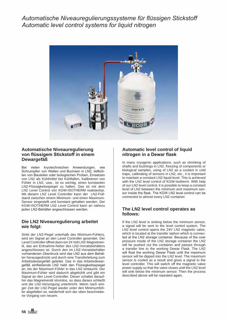
56 KGW
Automatische Niveauregulierungssysteme für flüssigen StickstoffAutomatic level control systems for liquid nitrogen
Automatische Niveauregulierung von flüssigem Stickstoff in einem DewargefäßBei vielen kryotechnischen Anwendungen, wie Schrumpfen von Wellen und Buchsen in LN2, tiefküh-len von Bauteilen oder biologischen Proben, Einsetzen von LN2 als Kühlmittel bei Kühlfallen, Kalibrieren von Fühler in LN2, usw., ist es wichtig, einen konstanten LN2-Flüssigkeitsspiegel zu halten. Das ist mit dem LN2 Level Control von KGW-ISOTHERM realisierbar. Mit diesem LN2 Level Controller kann der LN2-Füll-stand zwischen einem Minimum- und einen Maximum-Sensor eingestellt und konstant gehalten werden. Der KGW-ISOTHERM LN2 Level Control kann an nahezu jeden LN2-Behälter angeschlossen werden.
Die LN2 Niveauregulierung arbeitet wie folgt:Sinkt der LN2-Pegel unterhalb des Minimum-Fühlers, wird ein Signal an den Level Controller gesendet. Der Level Controller öffnet dann ein 24 Volt LN2-Magnetven-til, das am Entnahme-heber des LN2-Vorratsbehälters angeschlossen ist. Durch den im LN2-Vorratsbehälter vorhandenen Überdruck wird das LN2 aus dem Behäl-ter herausgedrückt und durch eine Transferleitung zum Arbeitsdewargefäß geleitet. Das in das Arbeitsdewar-gefäß einfließende LN2 hebt den Flüssigkeitsspiegel an, bis der Maximum-Fühler in das LN2 eintaucht. Der Maximum-Fühler wird dadurch abgekühlt und gibt ein Signal an den Level Controller. Dieser schaltet darauf-hin das Magnetventil stromlos, so dass dieses schließt und die LN2-Versorgung unterbricht. Wenn nach eini-ger Zeit der LN2-Pegel wieder unter den Minimumfüh-ler abgefallen ist, wiederholt sich der oben beschriebe-ne Vorgang von neuem.
Automatic level control of liquid nitrogen in a Dewar flaskIn many cryogenic applications, such as shrinking of shafts and bushings in LN2, freezing of components or biological samples, using of LN2 as a coolant in cold traps, calibrating of sensors in LN2, etc., it is important to maintain a constant LN2 liquid level. This is achieved with the LN2 level control of KGW-Isotherm. With help of our LN2 level control, it is possible to keep a constant level of LN2 between the minimum and maximum sen-sor inside the flask. The KGW LN2 level control can be connected to almost every LN2 container.
The LN2 level control operates as follows:If the LN2 level is sinking below the minimum sensor, a signal will be sent to the level control system. The LN2 level control opens the 24V LN2 magnetic valve, which is located at the transfer siphon which is connec-ted at the LN2 storage container. Because of the over pressure inside of the LN2 storage container the LN2 will be pushed out the container and passes through a transfer line to the working Dewar Flask. The LN2 will float the working Dewar Flask until the maximum sensor will be dipped into the LN2 level. The maximum sensor is cooled as a result and gives a signal to the level controller. This will switch off the magnetic valve power supply so that the valve closes until the LN2 level will sink below the minimum sensor. Then the process described above will be repeated again.

KGW 57
Automatische LN2-Niveauregulierung für manuelle Schrumpfungsvorrich-tungenUm manuelle oder automatische Verbindungen durch Schrumpfung sicher zu stellen, ist es wichtig, dass im-mer eine ausreichende Kühlung der zu schrumpfen-den Bauteile gewährleistet ist. Beim Schrumpfen von Buchsen oder Wellen, wird meistens LN2 als Kühlmit-tel eingesetzt. Durch ein automatisches LN2 Niveau-regelsystem kann die notwendige Kühlung mittels LN2 sichergestellt werden. Eine sichere Funktion der Schrumpfung ist somit gewährleistet.
Automatic LN2 - level control devices for manual shrinkingTo make manual or automatic connections safely through shrinking, it is important that a sufficient coo-ling is ensured at the shrinking components. LN2 is usually used as coolant for shrinking bushes or shafts. With help of an automatic LN2 level control system the necessary cooling can be ensured. The cooling via LN2 can be secured for the shrinking process.
1) LN2 Vorratsbehälter2) Heber mit Magnetventil3) Transferleitung4) LN2 Level Controller5) Abgasrohr6) Buchsen Halter7) Minimum-/ Maximum-Fühler8) zu schrumpfende Buchse9) Arbeitsdewargefäß
1) LN2 Storage container2) Siphon with magnetic valve3) Transfer line4) LN2 level control5) Exhausting pipe6) Bushes holder7) Min. max. sensor8) Sample / probe for shrinking9) Working Dewar flask
Automatische LN2-Niveauregulierung für manu-elle Schrumpfungsvorrichtungen mit zwei Halter für die zu schrumpfenden Buchsen, Dewarge-fäß, Deckel, Abgasrohr und einem 35 Liter LN2 Behälter. Best. Nr. 2760-35
Automatic LN2 - level control devices for ma-nual shrinking with two holder for the shrinking bushes, Dewar flask, lid, gas outlet tube and LN2 store vessel with 35 litre. Art.No. 2760-35

58 KGW
Automatische LN2 - Niveauregulierung bei Kühlfallen-AnwendungenAutomatic LN2 - level control devices for manual shrinking
Um die Kondensationsleistung einer Kühlfalle sicher zu stellen, ist es wichtig, einen weitestgehend kon-stanten LN2-Flüssig-keitspegel im Dewargefäß zu halten. Durch diesen konstanten LN2 Flüssigkeits-pegel wird sichergestellt, dass immer die gesamte Kondensatgefrierwand der Kühlfalle funktionsfähig ist und somit das Nutzvolumen der Kühlfalle genutzt werden kann. Der LN2-Füllstand kann mit dem LN2 Level Controller zwischen einem Minimum- und ei-nem Maximum-Sensor eingestellt und konstant ge-halten werden.
To make manual or automatic connections safe-ly through shrinking, it is important that a sufficient cooling is ensured at the shrinking components. LN2 is usually used as coolant for shrinking bushes or shafts. With help of an automatic LN2 level control system the necessary cooling can be ensured. The cooling via LN2 can be secured for the shrinking pro-cess.
1) LN2 Vorratsbehälter2) Heber mit Magnetventil3) Transferleitung4) LN2 Level Controller5) Abgasrohr6) Kühlfalle7) Minimum-/ Maximum-Fühler8) Phasenseparator9) Dewargefäß
1) LN2 Storage container2) Siphon with magnetic valve3) Transfer line4) LN2 level control5) Exhausting pipe6) Cold tap7) Min. max. sensor8) Phase separator 9) Dewar flask
Automatische LN2 - Niveauregulierung mit einer Edelstahl Kühlfalle Typ S 54V-K16-Z, Dewargefäß, Deckel, Abgasrohr und einem 25 Liter LN2 Behälter.Best. Nr. 2750-25
Automatic LN2 - level control with a stainless steal cold trap S 54V-K16-Z, Dewar flask, lid, gas outlet tube and LN2 store vessel with 25 litre. Art.No. 2750-25
Automatische LN2 - Niveauregulierung mit einer Glas Kühlfalle Typ SL29-GL-A, Dewargefäß, Deckel, Abgas-rohr und einem 25 Liter LN2 Behälter. Best. Nr. 2755-25
Automatic LN2 - level control with a glass cold trap SL 29 GL-A, Dewar flask, lid, gas outlet tube and LN2 store vessel with 25 litre. Art.No. 2755-25

KGW 59
AnwendungsbeispieleApplication Examples
Automatische LN2-Niveauregulierung an einem Dewargefäß für Zugversuche
Automatic LN2 - level control devices on a Dewar flask for a tension test
Automatische LN2-Niveauregulierung mit einem korrespondierenden Dewargefäß
Automatic LN2 - level control devices with a corresponding Dewar flask
Automatische LN2-Niveauregulierung mit zwei Dewargefäße
Automatic LN2 - level control devices with two Dewar flasks

60 KGW
technische Daten siehe rechte Seite / technical data see right page / caractéristiques techniques voir page de droite
Niveauregelgerät für flüssigen StickstoffLevel control for liquid nitrogen
Anwendung
- Niveauregelung von flüssigem Stickstoff (LN2 ) in offenen Dewar-Gefäßen- automatische Nachfüllvorricht- ung für flüssigen Stickstoff (LN2)- Das Gerät öffnet zur Befüllung das Magnetventil am Vorrats- tank
Vorteile
- manuelle oder automatische Befüllung- Kabelbruchsicherung der Sensoren- optische Anzeige des Schalt- zustandes- akustische und optische Fehleranzeige
Lieferumfang LEVEL CONTROL LN2
- zwei Temperaturfühler PT 100 (Minimum-, Maximum- Sensoren)- Regelgerät mit:- Anschluss LN2-Magnetventil(24V)- Sensor-Funktionsüberwachung
Artikelnummer
Typ: LEVEL CONTROL LN2Art.Nr: 1301
Application
- Level control of liquid nitrogen (LN2) in unsealed Dewar flasks- Automatic refill device for liquid nitrogen ( LN2 )- For refilling, the controller opens the magnetic valve at the reservoir tank
Advantages
- manual or automatic refill- cable break saving of sensors- visual indicator of switching status- audible and visual error display
Delivery LEVEL CONTROL LN2
- two temperature sensors PT 100 (minimum-, maximum sensors)- Controller incl.:- socket LN2- magnetic valve (24V)- function control for sensor
Article number
Type: LEVEL CONTROL LN2Art.No.: 1301
Art. Nr. 1301 Art. Nr. 1305 Art. Nr. 1304

KGW 61
Niveauregelgerät für flüssigen StickstoffLevel control for liquid nitrogen
Components
1) LN2 storage container2) LN2 transfer siphon3) LN2 transfer tube4) Working Dewar flask5) Min.- max. sensors6) LN2 Level Controller
Accessories
- Temperature sensor PT 100 Art.Nr: 1302
- Magnetic valve for liquid nitrogen (LN2) (24 V) Art.Nr: 1303
- LN2 transfer siphon with magnetic valve for reservoir tanks with safety device TYPE 1 Art.Nr: 1304
- LN2 transfer siphon with magnetic valve for reservoir tanks without safety device TYPE 2 Art.Nr: 1305
Komponenten
1) LN2 Vorratsbehälter2) LN2 Entnahmeheber3) LN2 Befüllleitung4) Arbeitsdewar5) Min.- Max. Fühler6) LN2 Level Controller
Zubehör
- Temperaturfühler PT 100 Art.Nr: 1302
- Magnetventil für flüssigen Stickstoff (LN2) (24 V) Art.Nr: 1303
- LN2 Entnahmeheber mit Magnetventil für Vorratsbehälter mit Sicherheitsarmatur TYP 1 Art.Nr: 1304
- LN2 Entnahmeheber mit Magnetventil für Vorratsbehälter ohne Sicherheitsarmatur TYP 2 Art.Nr: 1305

62 KGW
LN2 Niveauregulierung mit einer KühlfalleLN2 level control on a cold trap
Elektrischer Gaserzeuger für einen DruckaufbauElectrical gas generator for pressure
LN2 Behälter auf einem Rollwagen mit großen RädernLN2 cryo vessel on a rolling track with big rollers
Niveauregelgerät für flüssigen StickstoffLevel control for liquid nitrogen

KGW 63
Zubehör / Accessoires
BefülleinrichtungDie Befülleinrichtung ermöglicht das Befüllen eines Stickstoffbehälters ohne den Heber vom Behälter zu entfernen. Die Einrichtung besteht aus:1) Dem Befüllflansch mit LN2-Ventil, Abgasventil, Übergangsverschraubung, O-Ring und Spannring für NW 50. Befüllflansch Best. Nr.: 26062) Dem Befüllschlauch mit beidseitiger Überwurfmutter für die Übergangsverschraubung. Befüllschlauch Best.Nr.: 2607
Filling systemThe filling system is an equipment to fill in LN2 into a vessel without removing the LN2 siphon. The filling system is made of:1) The filling flange with LN2 valve, waste gas valve, screw adapter, O-ring and clamp for NW 50. Filling flange No.: 2606 2) The filling hose has got two screw couplings for the screw adapter. Filling hose No.: 2607
LN2 Behälter mit BefüllflanschLN2 cryo vessel with a fill-in flange
Niveauregelgerät für flüssigen StickstoffLevel control for liquid nitrogen

64 KGW
Vakuumisolierte Edelstahlbehälter für flüssigen Stickstoff Typ APOLLOVacuum-insulated stainless steel containers for liquid nitrogen Type APOLLO
EigenschaftenHohe mechanische Festigkeit, da der Behälter aus Edel-stahl gefertigt wird. Niedrige Verdampfungsrate durch Mehrschich-ten-Superisolation im Vakuumraum. Lange haltbar durch ro-buste konstruktive Auslegung, Fertigung und Materialauswahl. Lange Standzeit des Isoliervakuums durch den Einsatz von Getterwerkstoffen
Ausstattung serienmäßigIntergrierte Sicherheitseinrichtung am Behälterhals Vakuumverschluß mit SicherheitsventilLeichtgängige RollenKleinflanschanschluss KF NW 50Heber mit einem Abfüllschlauch mit MetallgewebeSchub- und Schutzrahmen.FüllstandsanzeigeDruckaufbau durch Flüssigkeitsentnahme ohne Fremdenergiezufuhr
CharacteristicsHigh mechanical stability, the container is made of stainless steel. Low evaporation rate by multi-layer superinsolation in the vacuum space. Very durable by robust constructive design, pro-duction and choice of material. Long-lasting insulating vacuum by the use of getter materials.
Standard epuipmentIntegrated safety devices at the container neckVacuum lock with safety valveEasy running castorsSmall-flange connection KF NW 50Transfer siphon with transfer hose covered with metallic tissueHand and protection ringContents gaugePressure attachment by fluid removal without external power supply
technische Daten siehe rechte Seite / technical data see right page / caractéristiques techniques voir page de droite

KGW 65
Abb. mit Druckaufbauregler (Sonderausstattung)With pressure built-up controller (optionally)
Flüssigstoff-Behälter aus Edelstahl zur Lagerung und Transport von flüssigen StickstoffLiquid nitrogen container made of stainless steel for storage and transport of liquid nitrogen
Technische Daten / Technical data
Typ / Type Apollo 50 100 150 200 350
Best. Nr. / Art. No. 2507 2508 2509 2510 2513
Geometrisches VolumenCapacity
(l) 49,5 99,2 149,5 198,5 348
BetriebsüberdruckMax. operating overpressure
(bar) 1,3 1,3 1,3 2,0 2,0
Gewicht leer / Weight empty (kg) 44 62 79 100 160
Gewicht voll / Weight full (kg) 85 145 204 266 450
Gesamthöhe / Overal height (cm) 80 114 146 117 165
Durchmesser / Diameter (cm) 50 50 50 70 70
Gesamtbreite / Overall width (cm) 65 65 65 80 80
Verdampfungsrate statischEvaporation rate static
(% / 24h ) 2,0 1,2 1,0 0,6 0,5
Technische Änderungen vorbehalten.All rights reserved for technical changes.

66 KGW
Flüssig-Stickstoffbehälter aus Edelstahl Typ JUNO, (20 L)Liquid nitrogen container out of Stainless Steel Type JUNO, (20 L)
Area of application- for liquid nitrogen (LN2)- pressure-less space for coolants- laboratory technology- medicinal technology- biotechnology- storing and transport
Features of performance- reliably and economically- low own weight- compact construction- nominal capacity 20 litres
Types and accessories- double wall, vacuum insulated aluminium vessel- multi-layer super insolation in the vacuum space- carrier ring with side grips - loose lid-on plug - vessel with KF NW 50 for a LN2- siphon - over pressure valve- manometer
Temperature range LN2 -196°C
Pressure range Pressure less or up to max. 1,3 bar
Safety advises and regulations- always wear protective glasses and protective gloves- national regulations for laboratories- company- guide lines- safety regulations for handling with liquid gases- ADR regulations
Evaporation rateDaily evaporation and static holding time were determined at 20°C, 1013 mbar, container stationary, lid closed and without transfer si-phon. These are nominal values that may change depending on the age and use of the container.
easy
robust
efficient
low-priced
Juno 20with KF NW 50 flange,over pressure valveand manometer
Anwendungsbereiche- für flüssigen Stickstoff- druckloser Kühlmittelraum- Labortechnik- Medizintechnik- Biotechnologie- Lagerung und Kurzstreckentransport
Leistungsmerkmale- zuverlässig und wirtschaftlich- Leicht, robust und zuverlässig - kompakte Bauform- Nennvolumen von 20 Liter
Ausführungen und Zubehör- Doppelwandig, vakuumisolierter Edelstahl- Superisolationsfolie im Vakuumraum- Tragering mit Griffe- Lose aufliegender Deckel- Behälterflansch KF NW 50 für LN2 Entnahmeheber- Überdruckventil- Manometer
Temperaturbereich- LN2 -196°C
Druckbereich- Drucklos oder bis max. 1,3 bar
Sicherheitshinweise und Richtlinien- Schutzbrille und Schutzhandschuhe tragen- Richtlinien für das Labor der BG- Betriebinterne Richtlinien- Sicherheitsrichtlinien für Umgang mit Flüssiggasen- ADR Richtlinien
VerdampfungsrateDie tägliche Verdampfung und die statistische Haltezeit wurden bei 20°C ,1013 Hektopascal, bei ruhig stehendem Behälter, ver-schlossenem Deckel und ohne Entnahmeheber ermittelt. Es sind Nominalwerte, die sich je nach Alter und Einsatz des Behälters verändern können.
Einfach
Robust
Effizient
Preiswert
Juno 20mit KF NW 50,
Überdruckventilund Manometer

KGW 67
Entnahmeschlauch aus Edelstahl / Transfer hose made of stainless steel
Art.-No. 2612
Entnahmerohr mit Phasenseparator / Transfer tube with phase separator
Art.-No. 2613
Verschraubungskupplung für Rohranschluß (D.a. = 8 mm) Screw coupling with tube fitting for pipe joint (D.a. = 8 mm), Art.-No. 2614
Übergangsverschraubung / Screw adapter Art.-No. 2615
Spannring und O-Ringdichtung mit Zentrierung Clamp and O-ring with centering
Art.-No. 2618 + 2619
Zubehör / Accessories
Entnahmeheber mit Übergangsverschraubung, Druck-ablaßhahn und Flüssigkeitshahn aus EdelstahlBest.-Nr. 2610
Transfer siphon incl. pressure reduction valve, fluid valve made of stainless steel and screw adapterArt.-No. 2610
2
4
3
15
Entnahmeheber Transfer siphon
Typ JUNO 20Best.-Nr. 2505
Geometrisches Volumen (l) 20
Betriebsüberdruck (bar) 1,3
Gewicht leer (kg) 13
Gewicht voll (kg) 29
Gesamthöhe (mm) 660
Durchmesser (mm) 394
Verdampfungsrate statisch (ca.L / Tag) 0,8
Statische Haltezeit (ca.Tage) 25
Rolluntersatz Best.-Nr. 2640-CD
Typ JUNO 20Art.-No. 2505
Capacity (l) 20
Max. operating overpressure (bar) 1,3
Weight empty (kg) 13
Weight full (kg) 29
Overall height (mm) 660
Diameter (mm) 394
Evaporation rate static (ca.L / Day) 0,8
Static holding time (ca. days) 25
Roller base Art.-No. 2640-CD
Flüssig-Stickstoffbehälter aus Edelstahl Typ JUNO, (20 L)Liquid nitrogen container out of Stainless Steel Type JUNO, (20 L)
Technische Daten Technical data

68 KGW
Zylindrische Dewargefäße aus Edelstahl für flüssigen Stückstoff zur Verwendung im Labor oder in der IndustrieCylindrical Dewar vessels made of stainless steel for liquid nitrogen for use in laboratories and industries
+ Hergestellt aus hoch korrosionsbeständigem Edelstahl+ Oberfläche metallisch blank geschliffen+ Mit Superisolation und Isolierdeckel+ Einfacher Transport durch Handgriffe+ Hohe Standfestigkeit+ Abgeflachter Innenboden
+ Manufactured out of high quality stainless steel + Surface with a brushed finish+ Use of super-insulating foil and insulating lid+ Easy carrying due to side grips+ High stability+ Flattened internal bottom
Typ DSS-D(Standard)
Typ DSS-DF(Sonderausführung
Custom made)

KGW 69
Dewargefäße Typ DSS - D mit Isolierdeckel und HandgriffenDewargefäße Typ DSS - DF mit Flansch auf Anfrage Auf Anfrage können auch Zwischengrößen und Sonderanfertigungen geliefert werden-
Dewar vessels Type DSS - D with insulating lid and side gripsDewar vessels Type DSS - DF with flange on requestIntermediate sizes and special designs can be supplied on request
Technische Änderungen vorbehalten / All rights reserved for technical changes
Typ DSS - D Typ DSS - DF
Zylindrische Dewargefäße aus EdelstahlCylindrical Dewar vessels made of stainless steel
Typ Di Da H.I. H.A. VolumenLiter Gewichtleerkg ArtikelNr.Type mm mm mm mm capacitylitres weightemptykg ArticleNo.
DSS - D 150 / 450 150 205 450 580 8 10 2401DSS - D 200 / 400 200 255 400 530 12,5 10 2402DSS - D 200 / 450 200 255 450 580 14 15 2403DSS - D 200 / 600 200 255 600 730 18 16 2404DSS - D 200 / 900 200 255 900 1030 28 17 2405DSS - D 250 / 300 250 305 300 430 14 13 2406DSS - D 250 / 450 250 305 450 580 22 17 2407DSS - D 250 / 600 250 305 600 730 30 18 2408DSS - D 250 / 750 250 305 750 880 37 24 2409DSS - D 250 / 1250 250 305 1250 1380 61 34 2410DSS - D 300 / 500 300 355 500 630 35 20 2411DSS - D 300 / 600 300 355 600 730 42,5 22 2412DSS - D 300 / 750 300 355 750 880 53 23 2413DSS - D 300 / 1250 300 355 1250 1380 88 35 2414DSS - D 400 / 500 400 458 500 630 63 30 2415DSS - D 400 / 750 400 458 750 880 94 39 2416DSS - D 400 / 800 400 458 800 930 100,5 40 2417DSS - D 400 / 1250 400 458 1250 1380 157 65 2418DSS - D 400 / 1350 400 458 1350 1480 170 68 2419DSS - D 500 / 800 500 557 800 930 157 58 2420DSS - D 500 / 1000 500 557 1000 1130 196 71 2421DSS - D 500 / 1300 500 557 1300 1430 255 95 2422DSS - D 600 / 1100 600 650 1100 1230 311 95 2423DSS - D 700 / 900 700 750 900 1030 346 97 2424DSS - D 900 / 900 900 1000 900 1030 572 125 2425

70 KGW
technische Daten siehe rechte Seite / technical data see right page / caractéristiques techniques voir page de droite
Technisches Datenblatt zu Cryobehälter aus Aluminium oder Edelstahl Typ BIOSAFETechnical data sheet for cryo vessel out of Aluminium or stainless steel Type BIOSAFE
Area of application
· storring of 2ml or 5 ml vials in liquid nitrogen or in the N2 gas phase · Laboratory technique· medicinal technique· Biotechnology
Features of performance
· reliably and economically· robustly and reliably· nominal capacity from 121 to 251 litres, optional 420 litres
Performance
BIOSAFE Including container con-trol and supervision with:
· Filling state announcement· Temperature announcement· LN2 Level regulation· LN2 filling stop when lid is open · Would pass away alarm announcements in text in clear· alarm exit free of potential for building technology
· and a lot more.
Anwendungsbereiche
· Lagerung von 2ml und 5 ml Ampullen in flüssigem Stickstoff oder optional in der Gasphase· Labortechnik· Medizintechnik· Biotechnologie
Leistungsmerkmale
· zuverlässig und wirtschaftlich· robust und zuverlässig · Nennvolumen von 121 bis 251 Liter, optional auch 420 Liter
Ausführung
· BIOSAFE inklusive Behälter- steuerung und Überwachung mit:
· Füllstandanzeige· Temperaturanzeige· LN2 Niveauregulierung· LN2 Füllstop bei geöffnetem Deckel· Verschiede Alarmmeldungen in Klartext· potentialfreier Alarmausgang für Gebäudetechnik
· und vieles mehr.
BIOSAFE aus Edelstahl 120 und 220 BIOSAFE made of stainless steel 120 and 220
BIOSAFE aus Aluminium Typ 40 und 60BIOSAFE made of Aluminium Type 40 and 60

KGW 71
Typ Biosafe BS 40 BS 60 BS 120 BS 220Material Aluminium Aluminium Edelstahl Edelstahl
Stainless steel Stainless steelBest.-Nr. / Art.-No. KGW 2320 2321 2322 2323
Geometrisches VolumenCapacity (l) 121 175 151 251
Volumen unterhalb des StellbodenCapacity under the platform (l) ca. 10 ca. 10 21 35
Gewicht leerWeight empty (kg) 43 53 100 175
HalsdurchmesserNeck diameter (mm) 216 216 514 664
GesamthöheOveral height (mm) 965 959 1045 1180
StellhöheHeight (mm) 560 560 625 625
DurchmesserDiameter (mm) 559 665 560 710
Verdampfungsrate statischEvaporation rate static (% / 24h ) 1,19 1,19 2,30 2,00
Typ / Type BS 40 BS 60 BS 120 BS 220Ampullentürme kleinvial racks, smallBest.-Nr. / Art.-No.
Typ ATK 4 x 85x854 x No. 2330
4 x 85x854 x No. 2330
Ampullentürme großvial racks, bigBest.-Nr. / Art.-No.
Typ ATG inklusiveincluded
inklusiveincluded
6 x 140x1456 x No. 2331
12 x 140x14512 x No. 2331
Anzahl der AmpullentürmeNumber of vial racks 4 6
Anzahl der EtagenNumber of stages 10 10 10 10
Größe der CryoboxenBest.-Nr. / Art.-No. TypATK 76x76mm
40xNo.265376x76mm
40xNo.2653
Size of the cryo boxesBest.-Nr. / Art.-No. Typ ATG 133x133mm
40xNo.2654133x133mm60xNo.2654
133x133mm60xNo.2654
133x133mm120xNo.2654
Anzahl pro Box Capacity per box
2ml(ATK)2ml(ATG) 100 100 25
10025
100
Anzahl der RöhrchenNumber of vials
Stückpiece 4000 6000 7000 13000
Technische Daten/Technical Data
Lagerkapazität für 2ml Röhren / Storage capacity of 2ml vials (Standard)

72 KGW
Flüssigstickstoff-Behälter aus Aluminium Typ ALULiquid nitrogen container made of aluminium Type ALU
Eigenschaften
Leichter Aluminiumbehälter mit Verbundwerkstoffen im HalsbereichNiedriges EigengewichtSuperisolationsfolie im VakuumraumGeringe Verdampfungsraten
Characteristics
Light aluminium container with compount materials in the neck rangeLow own weightSuper-insolation foil in the vacuum spaceLow evaporation rate
Ausstattung serienmäßig
Tragebügel oder HandgriffeVakuumventilKleinflansch KF NW 50Lose aufliegender Stopfen
Standard equipment
Handle or side gripsVacuum valveSmall-flange KF NW 50Loosely resting plug
technische Daten siehe rechte Seite / technical data see right page / caractéristiques techniques voir page de droite
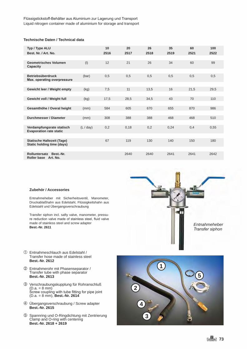
KGW 73
Entnahmeschlauch aus Edelstahl / Transfer hose made of stainless steel
Best.-Nr. 2612
Entnahmerohr mit Phasenseparator / Transfer tube with phase separator
Best.-Nr. 2613
Verschraubungskupplung für Rohranschluß (D.a. = 8 mm) Screw coupling with tube fitting for pipe joint (D.a. = 8 mm), Best.-Nr. 2614
Übergangsverschraubung / Screw adapter Best.-Nr. 2615
Spannring und O-Ringdichtung mit Zentrierung Clamp and O-ring with centering
Best.-Nr. 2618 + 2619
Zubehör / Accessories
Entnahmeheber mit Sicherheitsventil, Manometer, Druckablaßhahn aus Edelstahl, Flüssigkeitshahn aus Edelstahl und Übergangsverschraubung
Transfer siphon incl. safty valve, manometer, pressu-re reduction valve made of stainless steel, fluid valve made of stainless steel and screw adapterBest.-Nr. 2611
Flüssigstickstoff-Behälter aus Aluminium zur Lagerung und TransportLiquid nitrogen container made of aluminium for storage and transport
Technische Daten / Technical data
Typ / Type ALUBest. Nr. / Art. No.
102516
202517
262518
352519
602521
1002522
Geometrisches VolumenCapacity
(l) 12 21 26 34 60 99
BetriebsüberdruckMax. operating overpressure
(bar) 0,5 0,5 0,5 0,5 0,5 0,5
Gewicht leer / Weight empty (kg) 7,5 11 13,5 16 21,5 29,5
Gewicht voll / Weight full (kg) 17,5 28,5 34,5 43 70 110
Gesamthöhe / Overal height (mm) 584 605 670 655 870 986
Durchmesser / Diameter (mm) 308 388 388 468 468 510
Verdampfungsrate statischEvaporation rate static
(L / day) 0,2 0,18 0,2 0,24 0,4 0,55
Statische Haltezeit (Tage)Static holding time (days)
67 119 130 140 150 180
Rolluntersatz Best.-Nr.Roller base Art. No.
2640 2640 2641 2641 2642
2
4
3
15
Entnahmeheber Transfer siphon

74 KGW
technische Daten siehe rechte Seite / technical data see right page / caractéristiques techniques voir page de droite
Technisches Datenblatt zu Dewargefäßen aus AluminiumTyp ALU-CD
Technical data sheet for Dewar vessel out of Aluminiumtype ALU-CD
Area of application
· for liquid nitrogen (LN2)· pressure-less space for coolants· Laboratory technique· medicinal technique· Biotechnology· storing and transport
Features of performance
· reliably and economically· Low own weight · nominal capacity from 12 to 60 litres
Description of Alumini-um Dewar vessel
Types and accessories· double wall, vacuum insulated aluminium vessel· multi-layer superinsolation in the vacuum space· side grips or handle · Loosely resting plug · vessel with KF NW 50 for a LN2- siphon
Temperature range· LN2 -196°C
Pressure range· Press less or up to max. 0,5 bar
Anwendungsbereiche
· für flüssigen Stickstoff· druckloser Kühlmittelraum· Labortechnik· Medizintechnik· Biotechnologie· Lagerung und Kurzstrecken- transport
Leistungsmerkmale
· zuverlässig und wirtschaftlich· Leicht, robust und zuverlässig · Nennvolumen von 12 bis 60 Liter
Beschreibung der Gefäße
Ausführungen und Zubehör· Doppelwandige, vakuumisolierte Aluminiumbehälter· Superisolationsfolie im Vakuumraum· Tragegriffe oder Tragebügel· Lose aufliegender Deckel· Behälterflansch KF NW 50 für LN2 Entnahmeheber
Temperaturbereich· LN2 -196°C
Druckbereich· Drucklos oder bis max. 0,5 bar
ALU - CD 25 mit Entnahme-HeberALU - CD 25 with transfer siphon
ALU - CD 12 mit TragebügelALU - CD 12 with handle

KGW 75
Sicherheitshinweise und Richtlinien
· Schutzbrille und Schutzhandschuhe tragen· Richtlinien für das Labor der BG· Betriebinterne Richtlinien· Sicherheitsrichtlinien für den Umgang mit Flüssiggas
Safety advises and regulations
· always wear protective glasses and protective gloves· national regulations for laboratories· company- internal regulations· safety regulations for handling with liquid gases
Typ / Type ALU-CD 12 25 35 50 60
Best.-Nr. / Art. No. 2701 2702 2703 2704 2705
Geometrisches VolumenCapacity (l) 12,5 25 35 50 60
BetriebsüberdruckMax. operating overpressure (bar) 0,5 0,5 0,5 0,5 0,5
Gewicht leerWeight empty (kg) 8,1 10 13 17 20
Gewicht vollWeight full (kg) 18,1 31 41,5 57,5 68,5
GesamthöheOveral height (mm) 600 684 591 675 865
Durchmesser außenDiameter (mm) 310 395 480 500 486
Verdampfungsrate statischEvaporation rate static
(L / Tag)(L / day) 0,2 0,25 0,3 0,3 0,4
Rolluntersatz Best.-Nr.Roller base Art. No. 2640-CD 2641-CD 2642-CD 2641-CD
Entnahmeschlauch aus Edelstahl / Transfer hose made of stainless steel
Best.-Nr. 2612
Entnahmerohr mit Phasenseparator / Transfer tube with phase separator
Best.-Nr. 2613
Verschraubungskupplung für Rohranschluß (D.a. = 8 mm) Screw coupling with tube fitting for pipe joint (D.a. = 8 mm), Best.-Nr. 2614
Übergangsverschraubung / Screw adapter Best.-Nr. 2615
Spannring und O-Ringdichtung mit Zentrierung Clamp and O-ring with centering
Best.-Nr. 2618 + 2619
Zubehör / Accessories
Entnahmeheber mit Sicherheitsventil, Manometer, Druckablaßhahn aus Edelstahl, Flüssigkeitshahn aus Edelstahl und Übergangsverschraubung
Transfer siphon incl. safty valve, manometer, pressu-re reduction valve made of stainless steel, fluid valve made of stainless steel and screw adapterBest.-Nr. 2611
2
4
3
15
Entnahmeheber Transfer siphon

76 KGW
technische Daten siehe rechte Seite / technical data see right page / caractéristiques techniques voir page de droite
Dewargefäßen aus Aluminium Typ ALU-CD-DMT mit Schöpfkelle für die DermatologieDewar vessel out of Aluminium type ALU-CD-DMT with dipper for dermatology
ALU-CD 25-DMT mit Schöpfkelle und RolluntersatzALU-CD 25-DMT with dipper and roller base
ALU-CD 12-DMTmit SchöpfkelleALU-CD 12-DMT with dipper
Anwendungsbereiche
· Lagerung von flüssigem Stickstoff· Labortechnik· Medizintechnik· Biotechnologie· Lagerung und Kurzsteckentransport
Leistungsmerkmale
· zuverlässig und wirtschaftlich· Leicht, robust und zuverlässig· leichte LN2-Entnahme· einfaches tiefkühlen der Probe in LN2· Nennvolumen von 12 bis 35 Liter
Beschreibung der Gefäße Typ DMT
Ausführungen und Zubehör
· Doppelwandige, vakuumisolierte Aluminiumbehälter· Superisolationsfolie im Vakuumraum· Tragegriffe oder Tragebügel· Lose aufliegender Deckel· Behälterflansch KF NW 50 mit Schöpfkellenhalter· Schöpfkelle zur LN2-Entnahme
Temperaturbereich: LN2 -196°C
Druckbereich: Drucklos oder bis max. 0,5 bar
Area of application
· pressure-less space for coolants· Laboratory technique· medicinal technique· Biotechnology· storing and transport
Features of performance
· reliably and economically· low own weight· simple LN2 removal· easy cool down a sample in LN2· nominal capacity from 12 to 35 litres
Description of Aluminium Dewar vessel Type DMT
Types and accessories
· double wall, vacuum insulated aluminium vessel· multi-layer superinsolation in the vacuum space· side grips or handle· loosely resting plug· vessel with KF NW 50 and dipper holder· dipper to take out LN2
Temperature range: LN2 -196°C
Pressure range: Press less or up to max. 0,5 bar

KGW 77
Sicherheitshinweise und Richtlinien
· Schutzbrille und Schutzhandschuhe tragen· Richtlinien für das Labor der BG· Betriebsinterne Richtlinien· Sicherheitsrichtlinien für den Umgang mit Flüssiggase
Safety advises and regulations
· always wear protective glasses and protective gloves· national regulations for laboratories· company- internal regulations· safety regulations for handling with liquid gases
Technisches Datenblatt zu Typ ALU-CD-DMT mit SchöpfkelleTechnical data sheet for Type ALU-CD-DMT with dipper
SchöpfkelleDipper
SchöpfkellenhalterDipper holder
Typ / Type ALU-CD-DTM 12-DMT 25-DMT 35-DMT
Best.-Nr. 2701-DMT 2702-DMT 2703-DMT
Geometrisches VolumenCapacity (l) 12,5 25 35
Halsdurchmesser H 1Neck diameter H 1 (mm) 69 69 79
Gewicht vollWeight full (kg) 18,1 31 41,5
GesamthöheOveral height (mm) 600 684 591
Durchmesser außenDiameter outside (mm) 310 395 480
Schöpfkellen VolumenDipper capacity (ml) 60 60 60
Verdampfungsrate statischEvaporation rate static
(L/Tag)(L/day) 0,2 0,25 0,3
Rolluntersatz Best.-Nr.Roller base Art.-No. 2640-CD 2641-CD
Ersatzteile / Spare parts Best.-Nr.
SchöpfkelleDipper 2630
Schöpfkellenhalter für H1 = 69Dipper holder for H1 = 69 2631
Schöpfkellenhalter für H1 = 79Dipper holder for H1 = 79 2632

78 KGW
Flüssigstickstoff-Behälter aus Aluminium Typ BIO zur Lagerung und Transport von biologischen MaterialienLiquid nitrogen container made of aluminium Type BIO for storage and transport of biological materials
EigenschaftenLeichter Aluminiumbehälter mit Verbundwerk-stoffen im HalsbereichNiedriges EigengewichtSuperisolationsfolie im VakuumraumGeringe AbdampfratenDie Behälter erfüllen die internationalen Vor-schriften für den Transport auf der Straße (ADR)und der Schiene (RID)
Ausstattung serienmäßigTragebügel oder HandgriffeVakuumventilLose aufliegender StopfenInklusive KanisterKanister aus Kunststoff SerienmäßigKanister aus Edelstahl auf Anfrage
CharacteristicsLight aluminium container with compound materialsin the neck rangeLow own weightSuper-insulation foil in the vacuum spaceLow evaporation rateAll the vessels comply with international regulationsapplicable to the transport of hazardous goods byroad (ADR) or rail (RID).
Standard equipmentTransport handleVacuum valveLoose lied-on plugInclusive canisterCanister made of plastic, standardCanister made of stainless steal on request
technische Daten siehe rechte Seite / technical data see right page / caractéristiques techniques voir page de droite

KGW 79
Flüssigkeitsstickstoff-Behälter aus Aluminium Typ BIO zur Lagerung und Transport von biologischen MaterialienLiquid nitrogen container made of aluminium Type BIO for storage and transport of biological materials
Technische Daten / Technical data
Typ / Type BIO GT 2 GT 3 GT 9 GT 11 GT 18 GT 21 GT 26 GT 35 GT 38 GT 40
Best.-Nr. / Art. No. 2535/2 2535 2536-9 2537 2533 2538 2534 2539 2540 2541
Geometrisches VolumenCapacity
(l) 2 3,7 9,3 12,2 17,5 21 26,7 34 37 40
Gewicht leer / Weight empty (kg) 1,9 4,5 8,2 9,2 10,5 13 14,8 15 19 24
Gewicht voll / Weight full (kg) 3,5 7,5 16 19 25 31 36 43 49 57
HalsdurchmesserNeck diameter
(mm) 30 50 50 50 80 50 80 50 80 120
Gesamthöhe / Overal height (mm) 392 405 450 630 580 660 460 660 715 710
Durchmesser / Diameter (mm) 174 250 358 308 308 388 468 468 468 468
Verdampfungsrate statischEvaporation rate static
(L / day) 0,08 0,11 0,11 0,09 0,26 0,09 0,29 0,09 0,15 0,29
Statische StandzeitStatic holding time
(Tage)(days)
25 33 84 130 69 225 90 350 245 140
Kanister / canister 3 6 6 6 6 6 9 6 6 10Kunststoff / plastic X XEdelstahl / Stainless steel X X X X X X X X
Durchmesser KanisterDiameter of canister
(mm) 26 38 38 38 67 38 67 38 67 73
Höhe KanisterHeight of canister
(mm) 120 120 120 280 280 280 110 280 280 280
Rolluntersatz Best.Nr.Roller base Art. No.
2645 2646 2646 2646 2646
Anzahl von 2ml Ampullenim Ampullenhalter ( 6 Stück )
180 612 180 180 612 1200
Pailetten 0,25 ml 330 1560 1560 3120 9840 3120 7380 3120 9840 16400
Pailetten 0,5 ml 150 720 720 1440 4380 1440 3285 1440 4380 7300
Informationen zur Lagerung von 5 ml Ampullen auf Anfrage.Information about storing 5 ml vials on request.
Technische Änderungen vorbehalten.All rights reserved for technical changes.
Die tägliche Verdampfung und die statische Haltezeit wurden bei 20°C ,1013 Hektopascal, bei ruhig stehenden Behälter, verschlossenem Deckelund ohne Kanister bzw. Einhängesysteme ermittelt. Es sind Nominalwerte,die sich je nach Alter und Einsatz des Behälters verändern können.
Daily evaporation and static holding time are measured at 20°C,1013 mb, vessel stationary, lid closed and without inventory system. These values are nominal and can vary according to age and applicationof the container.

80 KGW
technische Daten siehe rechte Seite / technical data see right page / caractéristiques techniques voir page de droite
EigenschaftenLeichter Aluminiumbehälter mit Verbundwerkstoffenim HalsbereichNiedrige Verdampfungsrate Superisolationsfolie im VakuumraumNiedriges Eigengewicht
Ausstattung serienmäßigSeitliche Handgriffe Vakuum-Sicherheitsventil Elektronische Füllstandanzeige und Temperaturanzeige, Serveroption + Verbindung 20,4mA + RS485 + MEMO Rückverfolgbarkeit (+ Autofill)
ZubehörRolluntersatz
Flüssigkeitsstickstoff-Behälter aus Aluminium Typ ARPEGEzur Lagerung von biologischen MaterialienLiquid nitrogen container made of aluminium Type ARPEGEfor storage of biological materials
CharacteristicsLight aluminium container with compound materialsin the neck rangeLow evaporation rate Super-insulation foil in the vacuum spaceLow own weight
Standard equipmentHandleSafety vacuum valvelevel and temperature indicator, server option + connec-tion 20,4mA + RS485 + MEMO retraceability (+ autofill)
AccessoriesRoller base

KGW 81
Flüssigkeitsstickstoff-Behälter aus Aluminium Typ ARPEGE zur Lagerung von biologischen MaterialienLiquid nitrogen container made of aluminium Type ARPEGE for storage of biological materials
Technische Daten nur für LN2 Flüssigkeitslagerung / Technical data only for storage in liquid nitrogen (LN2)
Typ / Type ARPEGE A 40 A 70 A 110 A 140 A 170
Geometrisches Volumen / Capacity (l) 40 70 116 144 172
Gewicht leer / Weight empty (kg) 25 33 42 50 56
Gewicht voll / Weight full (kg) 57 91 136 166 195
Halsdurchmesser / Neck diameter (mm) 120 215 215 215 215
Gesamthöhe / Overal height (mm) 735 738 962 911 1028
Durchmesser / Diameter (mm) 467 586 586 683 683
Verdampfungsrate statischEvaporation rate static
(L / day) 0,30 0,60 0,65 0,65 0,70
Lagerkapazität für 2ml Röhren / Storage capacity of 2ml vials (Standard)
Einhängegestelle / Number of racks 6 4 4 6 6
Anzahl der Etagen / Number of stages 5 5 9 8 10
Größe der Cryoboxen / Size of the cryo boxes (mm) 76x76 133x133 133x133 133x133 133x133
Kryoboxen pro Behälter / cryo boxes per vessels Stück/piece 30 20 36 48 60
Anzahl pro Box / capacity per box 2 ml 25 100 100 100 100
Anzahl der Röhrchen / Number of vials 2 ml 750 2000 3600 4800 6000
Technische Änderungen vorbehalten / All rights reserved for technical changes.
Die tägliche Verdampfung und die statische Haltezeit wurden bei 20°C ,1013 Hektopascal, bei ruhig stehenden Behälter, verschlossenem Deckel und ohne Kanister bzw. Einhängesysteme ermittelt. Es sind Nominalwerte, die sich je nach Alter und Einsatz des Behälters verändern können.
Daily evaporation and static holding time are measured at 20°C, 1013 mb, vessel stationary, lid closed and without inventory system. These values are nominal and can vary according to age and application of the container.
Informationen zur Lagerung von Pailetten, Gasphasenlagerung und 5ml Ampullen auf Anfrage.Information about storing straws, gas storage or 5ml vials on request.
Typ / Type ARPEGE A 40 A 70 A 110 A 140 A 170
Bestell-Nr. / Art.- No.
BehälterfürFlüssigphasenlagerungohneRacksmitelektroni-scheFüllstandsanzeigeundTemperaturanzeige,Serveroption+Verbindung20,4mA+RS485+MEMORückverfolgbarkeit
Cryovesselforliquidstoragewithoutracks,withlevelandtemperatureindicator,serveroption+connection20,4mA+RS485+MEMOretraceability
2542 - L 2543 - L 2544 - L 2545 - L 2546 - L
BehälterfürFlüssigphasenlagerungohneRacksmitelektronischeFüllstandsanzeigeundTemperaturanzeige,Serveroption+Autofill+Verbindung20,4mA+RS485+MEMORückverfolgbarkeit
Cryovesselforliquidstoragewithoutracks,withlevelandtemperatureindicator,serveroption+autofill+connection20,4mA+RS485+MEMOretraceability
2543 - LA 2544 - LA 2545 - LA 2546 - LA
BehälterfürGasphasenlagerungohneRacksmitelektronischeFüllstandsanzeigeundTemperaturanzeige,Serveroption+Autofill+Verbindung20,4mA+RS485+MEMORückverfolg-barkeit
Cryovesselforgasstoragewithoutracks,withlevelandtemperatureindicator,serveroption+autofill+connection20,4mA+RS485+MEMOretraceability
2543 - GA 2544 - GA 2545 - GA 2546 - GA
Zubehör Accessories
Racks(1Satz) Racks(1set) 2542-R 2543-R 2544-R 2545-R 2546-R
Kryobox76x76für25Ampullen Cryobox76x76for25vials 2653
Kryobox133x133für100Ampullen Cryobox133x133for100vials 2654 2654 2654 2654
2mlAmpullen(100Stück) 2mlvials(100piece) 2652 2652 2652 2652 2652
Rolluntersatz Rollerbase 2649 2647 2647 2648 2648

82 KGW
EigenschaftenLeichter Aluminiumbehälter mit Verbundwerkstoffenim HalsbereichNiedrige Verdampfungsrate Superisolationsfolie im VakuumraumNiedriges EigengewichtDer flüssige Stickstoff ist in einer porösen Massegesichert Kein Auslaufen des flüssigen StickstoffesProbe lagert in der GasphaseErfüllt alle internationalen Vorschriften für denStraßenverkehr (ADR), Schiene (RID) und Luftverkehr (IATA-OACI)
Ausstattung serienmäßigVakuum-SicherheitsventilInklusive EinhängekanisterTragebügel oder Trageriemen
ZubehörSchutzverpackung für den Transport
Flüssigkeitsstickstoff-Behälter aus Aluminium Typ VOYAGEURzum sicheren Transport von biologischen MaterialienLiquid nitrogen container made of aluminium Type VOYAGEURfor the safety transport of biological materials
CharacteristicsLight aluminium container with compound materialsin the neck rangeLow evaporation rate Super-insulation foil in the vacuum spaceLow own weightThe liquid nitrogen is absorbed in a porous substanceNo risk of spilling liquid nitrogenThe samples are preserved in gaseous phase Complying with international regulations applicableto the transport of hazardous goods by road (ADR),rail (RID) and by air (IATA-OACI)
Standard equipmentSafety vacuum valveInclusive canistersHandle or carrying strap
AccessoriesProtective casing for transport
technische Daten siehe rechte Seite / technical data see right page / caractéristiques techniques voir page de droite

KGW 83
Flüssigkeitsstickstoff-Behälter aus Aluminium Typ VOYAGEUR für den sicheren Transport von biologischen MaterialienLiquid nitrogen container made of aluminium Type VOYAGEUR for safety transport of biological materials
Technische Daten / Technical data
Typ / Type VOYAGEUR V 2 V 5 V 12 Voyageur plus
Best.-Nr. / Art. No. 2548-V2 2548-V5 2548-V12 2549
Nutzinhalt / Capacity (l) 1,75 6,5 15 20,6
Davon in der porösen Masse / Absorbed capacity (l) 1,35 4,8 10,5 7,2
Gewicht leer / Weight empty (kg) 2,4 7,5 11,6 14,2
Gewicht voll / Weight full (kg) 3,5 11,3 20 20
Halsdurchmesser / Neck diameter (mm) 30 50 80 215
Gesamthöhe / Overal height (mm) 395 550 570 575
Durchmesser / Diameter (mm) 174 248 308 356
Verdampfungsrate statisch / Evaporation rate static (L / day) 0,10 0,13 0,24 0,80
Statische StandzeitStatic holding time
(Tage)(days)
13 37 44 9,5
KanisterCanister
Stückpiece
2 2 2
Durchmesser / Diameter (mm) 26 41 71
Höhe / Height (mm) 120 280 280
Lagerkapazität für 2ml Röhren / Storage capacity of 2ml vials
Anzahl der Röhrchen / Number of vials 2 ml 84 252 500bei Verwendung von Einhänge-
gestell 5 Etagen
Informationen zur Lagerung von 5 ml Röhren oder Pailetten auf AnfrageInformation about storing 5 ml vials or straws on request
Transport-Schutzverpackungen V 2 V 5 V 12 Plus
aus Kunststoff 2548-V2SK 2548-V5SK 2548-V12SK 2549-SK
Datenlogger zur Erfassung der Temperaturdaten während des Transportes
2548-DL 2548-DL 2548-DL 2548-DL
Technische Änderungen vorbehalten.All rights reserved for technical changes.
Die tägliche Verdampfung und die statische Haltezeit wurden bei 20°C ,1013 Hektopascal, bei ruhig stehenden Behälter, verschlossenem Deckel und ohne Kanister bzw. Einhängesysteme ermittelt. Es sind Nominalwerte, die sich je nach Alter und Einsatz des Behälters verändern können.
Daily evaporation and static holding time are measured at 20°C, 1013 mb, vessel stationary, lid closed and without inven-tory system. These values are nominal and can vary according to age and application of the container.

84 KGW
Was ist KALTGAS ?KALTGAS ist ein Temperiersystem für einen Tem-peraturbereich von –180°C bis +120°C, bei dem die eigentliche Temperiereinrichtung von der zu kühlen-den Probe räumlich getrennt ist. Tiefe Temperaturen werden durch den Einsatz von kaltem Stickstoffgas erreicht. Das Gas wird durch Verdampfung von flüs-sigem Stickstoff erzeugt, mit Hilfe eines Wärmetau-schers temperiert und durch eine isolierte Leitung zur Probe geleitet.Da bei KALTGAS-Anlagen das eigentliche Tempe-riersystem von der Probekammer abkoppelbar ist, kann eine einzige Anlage für verschiedene Kühl-anwendungen oder Temperierkammern eingesetzt werden. Eine weitere Besonderheit des KALTGAS-Systems ist die Kühlung von Proben im freien Raum. Hierbei wird die Probe im offenen Raum mit kaltem Stickstoffgas angeblasen. Somit kann man auch Bauteile oder Geräte im eingebauten Zustand oder während des Betriebes temperieren.
Anwendungsbeispiele– Thermische Prüfung von Kunststoffen, Metallen,
Verbundwerkstoffen usw.– Kühlung elektronischer Bauteile– Temperierung bei Prüfungen der Qualitätskont-
rolle– Schockgefrierung von biologischen Proben, Le-
bensmitteln, anderen Materialien– Temperierung von Versuchsproben bei: + Zug- oder Torsionsversuch + Kerbschlagversuch + Chemischen oder physikal. Versuchen + Verfahrenstechnischen Prozessen– Proben-Kühlung bei Diffraktometern, Spektro-
metern und Detektoren– Tieftemperatur- und Kryotechnik
AufbauKALTGAS-Anlagen arbeiten mit flüssigem Stickstoff als Kältemittel und zeichnen sich durch eine beson-ders hohe Kühlleistung aus. Eine KALTGAS-Anlage besteht aus den Komponenten:
– Regeleinheit– Flüssig-Stickstoff-Behälter– Stickstoff-Verdampfer– Isolierte Rohrleitung– ggf. Temperierkammer– Temperiermodul
Aufgrund des modularen Konzeptes des KALT-GAS-Systems kann jede Anlage genau auf die kun-denspezifischen Anforderungen angepaßt werden.
What is KALTGAS ?KALTGAS is a tempering system for a tem-perature range in between –180° C and +120° C with a se-paration of the primary tempering devices and the specimen that is to be cooled. Low temperatures are available by the use of cold nitrogen gas. The gas is generated by evapo-ration of liquid nitrogen, then tempered by a tempering module and guided through an insulated pipe to the specimen.Due to the separation of the primary tempering de-vice and the specimen chamber, it is possible to operate various test chambers with only one KALT-GAS system. Another feature of KALTGAS is the cooling of specimens in the free space. With this, the specimen is blown in the free space. It is there-fore possible to test components or units while as-sembled or in operation.
Examples of applications– Thermal testing of plastics, metals, compound
materials and so on.– Cooling of electronical components– Tempering at tests of the quality control– Shock-freezing of biological specimens, food
and other materials– Tempering of test specimens at + tension- torsion, or notched bar tests + chemical or physical tests + process engeneering– Specimen-cooling at diffractometers, spectro-
meters und detectors– low-temperature techniques and cryogenics
DesignKALTGAS systems work with liquid nitrogen as coo-ling agent and have therefore the advantage of a very high cooling performance. A KALTGAS system is designed by the following components:
– Control unit– Liquid nitrogen container– Nitrogen evaporator– Insolatad pipe– in the need a tempering chamber– Tempering module
Due to the modular concept of KALTGAS, every system can be designed exactly according to the costumer-related requirements.
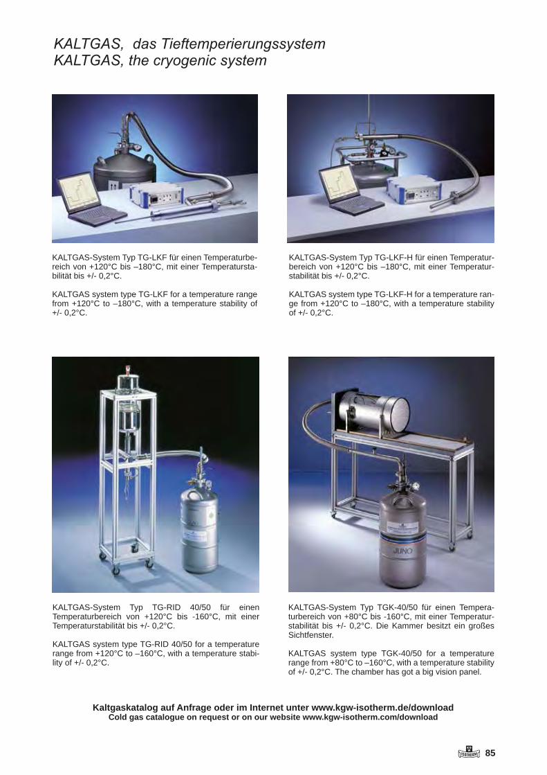
KGW 85
KALTGAS, das TieftemperierungssystemKALTGAS, the cryogenic system
KALTGAS-System Typ TG-LKF-H für einen Temperatur-bereich von +120°C bis –180°C, mit einer Temperatur-stabilität bis +/- 0,2°C.
KALTGAS system type TG-LKF-H for a temperature ran-ge from +120°C to –180°C, with a temperature stability of +/- 0,2°C.
KALTGAS-System Typ TGK-40/50 für einen Tempera-turbereich von +80°C bis -160°C, mit einer Temperatur-stabilität bis +/- 0,2°C. Die Kammer besitzt ein großes Sichtfenster.
KALTGAS system type TGK-40/50 for a temperature range from +80°C to –160°C, with a temperature stability of +/- 0,2°C. The chamber has got a big vision panel.
KALTGAS-System Typ TG-LKF für einen Temperaturbe-reich von +120°C bis –180°C, mit einer Temperatursta-bilität bis +/- 0,2°C.
KALTGAS system type TG-LKF for a temperature range from +120°C to –180°C, with a temperature stability of +/- 0,2°C.
KALTGAS-System Typ TG-RID 40/50 für einen Temperatur bereich von +120°C bis -160°C, mit einer Temperaturstabilität bis +/- 0,2°C.
KALTGAS system type TG-RID 40/50 for a temperature range from +120°C to –160°C, with a temperature stabi-lity of +/- 0,2°C.
Kaltgaskatalog auf Anfrage oder im Internet unter www.kgw-isotherm.de/downloadCold gas catalogue on request or on our website www.kgw-isotherm.com/download

86 KGW
KALTGAS ist ein Temperierungssystem, das auf der tiefen Temperatur des flüssigen Stickstoffes als Kältemittel aufbaut. Der flüssige Stickstoff wird in einem Kryobehälter mittels einer Heizung (Jet) verdampft. Hierdurch wird ein konstanter, tiefkal-ter Gasstrom erzeugt. Durch Variieren der Heizung (Jet) am Sicherheits-Controller (SC5), kann sowohl die Kühlleistung, als auch das Gasstromvolumen verändert werden, ebenso kann man durch Vari-ieren der Jet-Leistung der LN2-Verbrauch auf ein Minimum reduzieren. Der tiefkalte Gasstrom wird anschließend durch eine vakuumisolierte, flexible Metallleitung zu einem Wärmetauscher (Heater) geführt. Der Wärmetauscher hat die Aufgabe, den kalten Gasstrom auf die gewünschte Temperatur zu erwärmen. Somit steht am Ausgang des Kaltgas-schlauches ein fest definierter Gasstrom mit einer fest definierten Temperatur als Kühlgas zur Verfü-gung. Ein KALTGAS-System kann innerhalb von wenigen Minuten einen –170°C kalten Gasstrom erzeugen. Der Einsatz verschiedener Tempera-turregler, ermöglicht den optimalen kundenspezifi-schen Aufbau eines KALTGAS-Systems. Mit einem Standard Sicherheits-Controller (SC5) erreicht man eine Temperaturstabilität kleiner +/-0,2°C.
Mit diesem konstanten Gasstrom kann zum Beispiel eine Kammer temperiert werden. (siehe Typ TGK). Neben der hohen Abkühlgeschwindigkeit und der guten Regelstabilität ist der modulare Aufbau ein weiterer Vorteil von KALTGAS-Systemen. Durch Austauschen einzelner Bauteile, wie z.B. der N2-Gasleitung, des Jets oder des Heaters, kann die Abkühlgeschwindigkeit oder der LN2 Verbrauch, sowie die Einsatzart, verändert werden. Die Grund-module wie LN2-Behälter, Vakuumpumpe oder Temperaturregelung bleiben unverändert.
KALTGAS is a tempering system that utilizes the very low temperature of liquid nitrogen as a coo-ling agent. The Jet vaporizes the liquid nitrogen in a cryogenic container, producing a steady cryoge-nic gas flow. This LN2 vaporizer (Jet) can be ad-justed to minimize liquid nitrogen consumption and to change both the cooling rate and the volume of the gas flow. The cryogenic gas flow is then piped through a vacuum insulated flexible metal line (N2 gas line) to a heat exchanger (heater). The heat exchanger is designed to heat the cold gas flow to the desired temperature. The final product, a clearly quantified gas flow exiting the heat exchanger at a clearly defined temperature, is ready for use as a cooling agent. A KALTGAS system needs only a few minutes to produce a cold gas flow with a tempera-ture of -170°C (-274°F). Configuring the KALTGAS system to any customer‘s individual environment is possible thanks to various temperature controllers that can be embedded inside the safety control unit. Those temperature controllers are available with or without interfaces. With the standard safety control unit (SC5) , a temperature stability of better than ± 0.2°C can be achieved. The steady gas flow can be used to temper a chamber (TG-K KALTGAS).
In addition to their high cooling speed and good control stability, another advantage of KALTGAS systems is their modular design. By swapping out individual modules such as the N2 gas line, the LN2 vaporizer (Jet) or the heater, it is possible to change the cooling speed, LN2 consumption as well as the application. The basic modules, including the LN2 container, the vacuum pump and the safety control unit, remain unchanged.
Kaltgas Tieftemperatursystem Typ TG-LKF-Hfür den Temperaturbereich von +120°C bis -180°C
Kaltgas cooling system type TG-LKF-Hfor cooling applications from +120°C (+248°F) to -180°C (-292°F)

KGW 87
Technische Daten:
Typ TG-LKF-H 63/50
Ln2 Verdampfer (Jet) = 500 Watt Heater = 630Watt LN2 Verbrauch ca. 1,1 l/h bis 11 l/h Liter pro StundeRohrleitung V2A, Länge1,8 Meter, mit Vak. Pumpeund Gasaustrittsdüse = KF NW 40,Heber für LN2-Behälter mit KF NW 50
Best. Nr. TG-LKF-H 63/50
Zubehör: LN2-Behälter von 20 Liter bis 350 Liter Volumen
Weitere Leistungen von KALTGAS-Systemen auf Anfrage. Technische Änderungen vorbehalten
Technical data:
Model TG-LKF-H 63/50
LN2 vaporizer (Jet)= 500 wattsHeater = 630 wattsLN2 consumption = 1.1l/h to 11l/h (liters per hour)N2 gas line = V2A, length 1.8 meters, flexible, with vacuum pump and gas outlet noozle = KF NW 40,siphon for LN2 container with KF NW 50
Order No.: TG-LKF-H 63/50
Accessories: LN2 container with 20 to 350 liter capacity
Further information on KALTGAS systems available.Technical data subject to change.
-200
-150
-100
-50
0
50
Tem
p. C
°
Minuten / minutes
Gas‐Temperaturactual temperature
Sollwertset point
88 KGW
ReaktionsgefäßeReaction vesselsRécipients de réaction
All reaction vessels manufactured by KGW-ISOTHERM are based on plane flange system by Schott (NW 60 to NW 200). This standardised flange system provides customers with a comprehen-sive range of accessories and replace-ment parts. The O-ring groove in the vessel‘s flange facilitates simple and safe mounting of the vessel with the as-sociated lid.
Our reaction vessels are offered accor-ding to standard in 3 versions: single-walled, double-walled and triple-walled. Vessels with, or without bottom outlet. Such bottom outlet can e.g. be a valve or a spherical joint.
There are different thermal-jacket con-nections possible for heatable reaction vessels. Beside the classic plane flan-ges DN15 or DN 25 also glass threads with plastic screw olives are offered.
All reaction vessels including the stan-dard types are only made on customer’s order. Therefore, modifications to joints or flanges are usually offered at no extra cost.
For reaction vessels with an indicated operating overpressure a temperature difference inside the glass wall of 50 K (for three-wall vessels 30 K) may not to be exceeded. Fore more information please have a look into our operating manuals under download on our web-site.
Each manufactured reaction vessel is compression tested after its production. Therefore the reactor must stand the one and a half time of nominal pressure at ambient temperature.
Other versions than those described here are always possible. On request we can supply you with a professional over-view of our products per CAD drawings. A comprehensive range of accessories completes our program of reaction ves-sels. This is so large that it cannot be reproduced in the catalogue. If you need parts that are not shown, please do not hesitate to contact us. We will try to offer the desired part or a suitable alternative, then.
Alle von KGW-ISOTHERM hergestell-ten Reaktionsgefäße bauen auf dem Planflansch-System von Schott (NW 60 bis NW 200) auf. Mit diesem genormten Flanschsystem steht dem Kunden ein umfangreiches Zubehör- und Ersatzteil-programm zur Verfügung. Durch die O-Ringnut im Gefäßflansch ist ein leichter und sicherer Aufbau des Gefäßes mit dem dazugehörigen Deckel möglich.
Unsere Reaktionsgefäße werden stan-dardmäßig in 3 Versionen angeboten: einwandig, doppelwandig und dreiwan-dig. Gefäße mit oder ohne Bodenablauf. Solch Bodenablauf kann z.B. ein Ventil oder ein Kugelschiff sein.
Bei temperierbaren Reaktionsgefäßen sind verschiedene Kühlmittelanschlüsse möglich. Neben den klassischen Plan-flanschen DN15 oder DN 25 werden auch Glasgewinde mit abschraubbaren Kunststoffoliven angeboten.
Alle Reaktionsgefäße, auch die Stan-dardtypen, werden nach Kundenauftrag produziert. Änderungen bei Anschlüs-sen oder Flansche werden daher meist ohne Aufpreis angeboten.
Bei Reaktionsgefäßen mit einem ange-gebenen Betriebsüberdruck darf eine Temperaturdifferenz in der Glaswand von 50 K (für Dreiwandgefäße 30 K) nicht überschritten werden. Weitere In-formationen hierzu finden Sie in den Be-triebsanleitungen unter Downloads im Internet.
Alle Reaktionsgefäße werden nach der Herstellung einer Einzeldruckprüfung im Werk unterzogen. Dabei wird das Reak-tionsgefäß mit dem 1,5 - fachen Nenn-druck bei Raumtemperatur geprüft.
Außer den hier aufgeführten Ausführun-gen sind auf Wunsch weitere Ausfüh-rungen jederzeit möglich. Mittels CAD wird Ihnen ein qualifiziertes Angebot mit Zeichnung unterbreitet. Ein umfangrei-ches Zubehörprogramm rundet den Be-reich der Reaktionsgefäße ab. Nicht alle Zubehörteile können in unseren Katalog abgebildet werden. Sollten Sie nicht ab-gebildete Bauteile benötigen, fragen Sie diese bitte an. Wir werden versuchen, Ihnen dann das gewünschte Teil oder eine Alternative anzubieten.
Tout récipient de réaction fabriqué par KGW-Isotherm est conçu sur la base de la technique de rodage plan de Schott (DN 60 à DN 200). Grâce à cette tech-nique normalisée, notre clientèle tire entièrement profit du grand nombre d’accessoires et de pièces de rechange offert. De plus, la rainure judicieuse, réa-lisée dans le rodage plan du récipient pour accueillir le joint torique, assure un assemblage facile et fiable du récipient avec son couvercle.
Nos récipients de réaction sont disponi-bles en trois modèles standard différents : à simple paroi, à double paroi et à triple paroi. Récipients avec ou sans vidan-ge au fond. Cela signifie que le fond du récipient peut être doté, par exemple, d’une vanne de vidange ou d’un rodage sphérique.
Les récipients de réaction résistants à la chaleur permettent diverses possibilités de raccordement de réfrigérants. C’est ainsi que nous proposons, outre les rodages plans classiques d’un diamèt-re nominal DN15 ou DN 25, aussi des embouts filetés en verre fermés par des olives plastique qui se laissent dévisser.
Nos récipients de réaction, y compris les types standard, sont tous réalisés selon les spécifications du client. Cela nous permet, dans la plupart des cas, de renoncer à une majoration des prix lorsque nous adaptons les raccords ou rodages.
Si les récipients de réaction seront ex-posés à des surpressions de service, qui doivent être indiquées, la fluctuation de la température agissant sur la paroi en verre ne doit pas excéder 50 K (30 K pour la paroi triple). Vous trouverez de plus amples informations à ce sujet dans les instructions de service téléchargeab-les sur internet.
Avant que nos récipients de réaction quittent notre usine, nous les soumet-tons individuellement à un contrôle de solidité. Dans ce cadre, chaque récipient de réaction doit résister à une pression nominale multipliée par 1,5 lorsqu’il règ-ne une température ambiante normale.
Demandez-nous aussi d’autres modèles que nous sommes en mesure de réali-ser à tout moment, selon vos exigences. Nous vous soumettrons volontiers une offre qualifiée, y compris le dessin DAO appartenant. Mais cela n’est pas tout. Vous bénéficierez également de not-re vaste gamme d’accessoires pour le secteur des récipients de réaction pour laquelle, pour des raisons de volume du catalogue, nous ne sommes pas en me-sure de spécifier tous les éléments. Si vous ne trouvez pas l’accessoire requis parmi les composants représentés, il vous suffira donc de nous le demander. Nous entreprendrons tout afin de vous satisfaire soit par la pièce souhaitée, soit par une pièce équivalente.
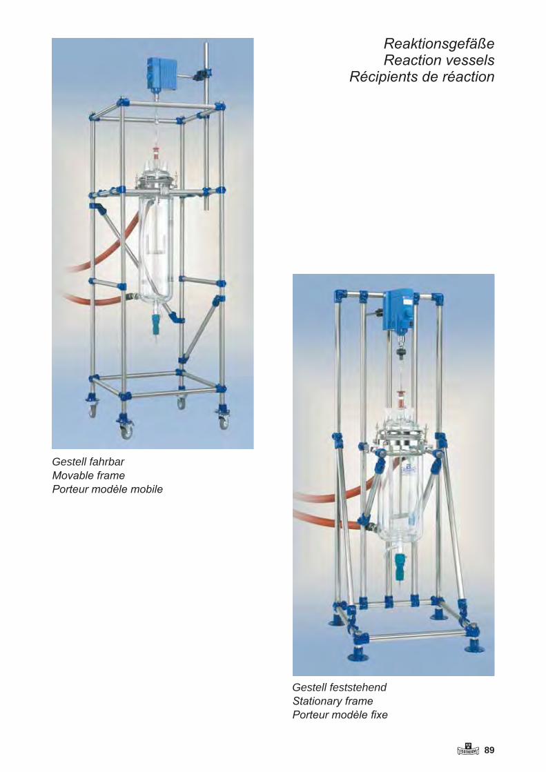
KGW 89
ReaktionsgefäßeReaction vessels
Récipients de réaction
Gestell fahrbarMovable framePorteur modèle mobile
Gestell feststehendStationary framePorteur modèle fixe

90 KGW
1) Reaktor Volumen (Seite 65 bis 71) Flanschgröße NW 60 bis 200 Ablaufventil ( Ventil Typ L oder Typ J) Temperiermantelanschlüsse ( GL 18 oder DN 15)
2) Temperiermantelanschluss DN 15 Metalladapter DN 15 (Seite 75) Dichtung DN 15 ( Silicon oder PTFE) Temperierschlauch (0,5 bis 3 Meter)
3) Deckel Flanschgröße NW 60 bis 200 (Seite 72 und 73) Anschluss mittig (NS 29/32 oder NS 45/40) Anschluss seitlich ( 14/23 bis NS 45/40 / (schräg oder gerade)
4) O-Ring Größe NW 60 bis NW 200 (Seite 76) Silikon FEP – ummantelt
5) Rührer Rührerwelle ( 8,10 oder 16mm) (Seite 78 und 79) Ankerrührer Propellerrührer
6) Rührverschluss Anschluss (NS 29/32 oder NS 45/40) (Seite 81) Standard - Rührverschluss PTFE-Rührverschluss Magnet-Rührverschluss
7) Rührkupplung Rührerwelle ( 8,10 oder 16mm) (Seite 80) Typ RKS Typ RKG Typ RKK
8) Verschluss und Halter Größe NW 60 bis NW 200 für Reaktoren Typ Vario Grip (Seite 76 und 77) Typ Universalverbinder Typ Einhängeverbinder
9) Gestelle Tischgestell (Seite 82 und 83) Feststehendes Gestell Fahrbares Gestell Easy Frame
Weiteres Zubehör auf Anfrage.
Was benötigt man für einen kompletten Reaktor mit Zubehör

KGW 91
1) reactor capacity (page 65 to 71) size of flange NW 60 to 200 outlet valve ( valve type L or type J) thermal jacket connection ( GL 18 or DN 15)
2) thermal jacket connection DN 15 metal adapter DN 15 (page 75) sealant DN 15 ( silicone or PTFE) thermal jacket hose ( 0,5 to 3 meters)
3) reactor lid size of flange NW 60 to 200 (page 72 and 73) centre socket ( NS 29/32 or NS 45/40) side socket ( NS 14/23 to NS 45/40 / straight or angled)
4) O-ring size NW 60 to 200 (page 76) silicone FEP-coated
5) stirrer shaft of stirrer ( 8,10 or 16 mm) (page 78 and 79) anchor stirrer propeller stirrer
6) dynamic seals for stirrer joint ( NS 29/32 or 45/40) (page 81) standard dynamic stirrer seal PTFE-stirrer seal magnetic stirrer coupling
7) coupling for stirrer shaft of stirrer ( 8,10 or 16 mm) (page 80) type RKS type RKG type RKK
8) seal and holdersize NW 60 to 200 for reaction vessels type ”Vario Grip” (page 76 and 77) type universal supporting device type supporting device
9) frames table frame (page 82 and 83) stationary frame movable frame cylindrically Easy Frame
Further accessories on request.
What do you need for a complete reactor with accessories

92 KGW
65
Reaktionsgefäße zylindrisch
Reaction vessels cylindrically
Récipients de réaction cylindrique
Reaktionsgefäße zylindrisch mit „L“ Ventil
Reaction vessels cylindrically with „L“ valve
Récipients de réaction cylindrique avec vanne „L“
B e st.N r V o lu m e n D .A . F .H . H . I . F la n sch B .D .b a r
TR G N 6937 250 70 100 130 N W 60 2 ,5 ba rTR G N 6935 500 70 190 220 N W 60 2 ,5 ba rTR G N 6936 1000 70 380 410 N W 60 2 ,5 ba r
TR G N 6941 500 110 80 110 N W 100 1 ,5 ba rTR G N 6942 1000 110 150 180 N W 100 1 ,5 ba rTR G N 6943 2000 110 270 300 N W 100 1 ,5 ba rTR G N 6944 3000 110 390 420 N W 100 1 ,5 ba rTR G N 6945 4000 110 530 560 N W 100 1 ,5 ba r
TR G N 6956 500 130 60 90 N W 120 1 ,3 ba rTR G N 6957 1000 130 100 130 N W 120 1 ,3 ba rTR G N 6958 2000 130 190 220 N W 120 1 ,3 ba rTR G N 6959 3000 130 280 310 N W 120 1 ,3 ba rTR G N 6960 4000 130 360 390 N W 120 1 ,3 ba rTR G N 6961 5000 130 460 490 N W 120 1 ,3 ba rTR G N 6962 6000 130 540 570 N W 120 1 ,3 ba r
TR G N 6948 4000 160 240 280 N W 150 1 ,0 ba rTR G N 6949 5000 160 290 330 N W 150 1 ,0 ba rTR G N 6950 6000 160 350 390 N W 150 1 ,0 ba rTR G N 6951 8000 160 460 500 N W 150 1 ,0 ba rTR G N 6952 10000 160 580 620 N W 150 1 ,0 ba r
TR G N 6963 5000 215 160 200 N W 200 0 ,5 ba rTR G N 6964 6000 215 200 240 N W 200 0 ,5 ba rTR G N 6965 8000 215 260 300 N W 200 0 ,5 ba rTR G N 6966 10000 215 320 360 N W 200 0 ,5 ba rTR G N 6967 15000 215 500 540 N W 200 0 ,5 ba rTR G N 6967-20 20000 215 650 725 N W 200 0 ,5 ba r
Be st.Nr V olum e n D.A. F .H. H.I. F la nsch B.D.ba r
TRG N 6901 250 70 100 130 NW 60 2,5 barTRG N 6902 500 70 190 220 NW 60 2,5 barTRG N 6903 1000 70 380 410 NW 60 2,5 bar
TRG N 6908 500 110 80 110 NW 100 1,5 barTRG N 6909 1000 110 150 180 NW 100 1,5 barTRG N 6910 2000 110 270 300 NW 100 1,5 barTRG N 6911 3000 110 390 420 NW 100 1,5 barTRG N 6912 4000 110 530 560 NW 100 1,5 bar
TRG N 6923 500 130 60 90 NW 120 1,3 barTRG N 6924 1000 130 100 130 NW 120 1,3 barTRG N 6925 2000 130 190 220 NW 120 1,3 barTRG N 6926 3000 130 280 310 NW 120 1,3 barTRG N 6927 4000 130 360 390 NW 120 1,3 barTRG N 6928 5000 130 460 490 NW 120 1,3 barTRG N 6929 6000 130 540 570 NW 120 1,3 bar
TRG N 6914 4000 160 240 280 NW 150 1,0 barTRG N 6915 5000 160 290 330 NW 150 1,0 barTRG N 6916 6000 160 350 390 NW 150 1,0 barTRG N 6917 8000 160 460 500 NW 150 1,0 barTRG N 6918 10000 160 580 620 NW 150 1,0 bar
TRG N 6930 5000 215 160 200 NW 200 0,5 barTRG N 6931 6000 215 200 240 NW 200 0,5 barTRG N 6932 8000 215 260 300 NW 200 0,5 barTRG N 6933 10000 215 320 360 NW 200 0,5 barTRG N 6934 15000 215 500 540 NW 200 0,5 barTRG N 6934-20 20000 215 650 725 NW 200 0,5 bar
Reaktionsgefäße zylindrischReaction vessels cylindricallyRécipients de réaction cylindrique
Reaktionsgefäße zylindrisch mit "L" VentilReaction vessels cylindrically with "L" valveRécipients de réaction cylindrique avec vanne „L“
Art.Nr Volumen D.A. F.H. H.I. Flansch B.D.barTRGN 6901 250 70 100 130 NW 60 2,5 barTRGN 6902 500 70 190 220 NW 60 2,5 barTRGN 6903 1000 70 380 410 NW 60 2,5 barTRGN 6908 500 110 80 110 NW 100 1,5 barTRGN 6909 1000 110 150 180 NW 100 1,5 barTRGN 6910 2000 110 270 300 NW 100 1,5 barTRGN 6911 3000 110 390 420 NW 100 1,5 barTRGN 6912 4000 110 530 560 NW 100 1,5 barTRGN 6923 500 130 60 90 NW 120 1,3 barTRGN 6924 1000 130 100 130 NW 120 1,3 barTRGN 6925 2000 130 190 220 NW 120 1,3 barTRGN 6926 3000 130 280 310 NW 120 1,3 barTRGN 6927 4000 130 360 390 NW 120 1,3 barTRGN 6928 5000 130 460 490 NW 120 1,3 barTRGN 6929 6000 130 540 570 NW 120 1,3 barTRGN 6914 4000 160 240 280 NW 150 1,0 barTRGN 6915 5000 160 290 330 NW 150 1,0 barTRGN 6916 6000 160 350 390 NW 150 1,0 barTRGN 6917 8000 160 460 500 NW 150 1,0 barTRGN 6918 10000 160 580 620 NW 150 1,0 barTRGN 6930 5000 215 160 200 NW 200 0,5 barTRGN 6931 6000 215 200 240 NW 200 0,5 barTRGN 6932 8000 215 260 300 NW 200 0,5 barTRGN 6933 10000 215 320 360 NW 200 0,5 barTRGN 6934 15000 215 500 540 NW 200 0,5 barTRGN 6934-20 20000 215 650 725 NW 200 0,5 bar
Art.Nr Volumen D.A. F.H. H.I. Flansch B.D.barTRGN 6937 250 70 100 130 NW 60 2,5 barTRGN 6935 500 70 190 220 NW 60 2,5 barTRGN 6936 1000 70 380 410 NW 60 2,5 barTRGN 6941 500 110 80 110 NW 100 1,5 barTRGN 6942 1000 110 150 180 NW 100 1,5 barTRGN 6943 2000 110 270 300 NW 100 1,5 barTRGN 6944 3000 110 390 420 NW 100 1,5 barTRGN 6945 4000 110 530 560 NW 100 1,5 barTRGN 6956 500 130 60 90 NW 120 1,3 barTRGN 6957 1000 130 100 130 NW 120 1,3 barTRGN 6958 2000 130 190 220 NW 120 1,3 barTRGN 6959 3000 130 280 310 NW 120 1,3 barTRGN 6960 4000 130 360 390 NW 120 1,3 barTRGN 6961 5000 130 460 490 NW 120 1,3 barTRGN 6962 6000 130 540 570 NW 120 1,3 barTRGN 6948 4000 160 240 280 NW 150 1,0 barTRGN 6949 5000 160 290 330 NW 150 1,0 barTRGN 6950 6000 160 350 390 NW 150 1,0 barTRGN 6951 8000 160 460 500 NW 150 1,0 barTRGN 6952 10000 160 580 620 NW 150 1,0 barTRGN 6963 5000 215 160 200 NW 200 0,5 barTRGN 6964 6000 215 200 240 NW 200 0,5 barTRGN 6965 8000 215 260 300 NW 200 0,5 barTRGN 6966 10000 215 320 360 NW 200 0,5 barTRGN 6967 15000 215 500 540 NW 200 0,5 barTRGN 6967-20 20000 215 650 725 NW 200 0,5 bar
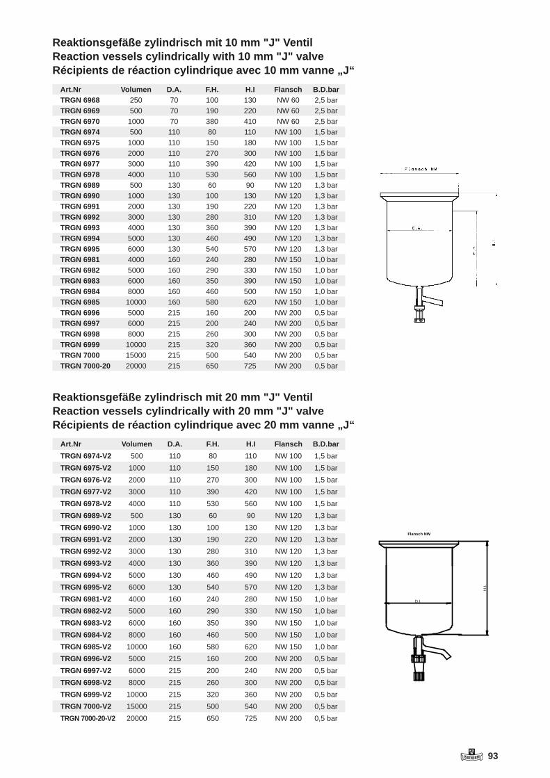
KGW 93
66
Reaktionsgefäße zylindrisch mit „J“ Ventil
Reaction vessels cylindrically with „J“ valve
Récipients de réaction cylindrique avec vanne „J“
Temperierbare Reaktionsgefäße mit Heizmantelanschluss GL18-Olive
Heatable reaction vessels with thermal jacket connection GL18-Olive
Réacteurs thermostatable avec connecteur pour enveloppe GL18-Olive
Be st.Nr V olum e n D.A. D.I. F.H. H.I. Fla nsch B.D.ba r
TRGN 7001 250 100 60 100 150 NW 60 2,5 barTRGN 7002 500 100 60 190 240 NW 60 2,5 barTRGN 7003 1000 100 60 380 430 NW 60 2,5 bar
TRGN 7007 500 140 100 80 140 NW 100 1,5 barTRGN 7008 1000 140 100 150 210 NW 100 1,5 barTRGN 7009 2000 140 100 270 330 NW 100 1,5 barTRGN 7010 3000 140 100 390 450 NW 100 1,5 barTRGN 7011 4000 140 100 530 590 NW 100 1,5 bar
TRGN 7022 500 160 120 60 120 NW 120 1,3 barTRGN 7023 1000 160 120 100 160 NW 120 1,3 barTRGN 7024 2000 160 120 190 250 NW 120 1,3 barTRGN 7025 3000 160 120 280 340 NW 120 1,3 barTRGN 7026 4000 160 120 360 420 NW 120 1,3 barTRGN 7027 5000 160 120 460 520 NW 120 1,3 barTRGN 7028 6000 160 120 540 600 NW 120 1,3 bar
TRGN 7013 4000 200 150 240 315 NW 150 1,0 barTRGN 7014 5000 200 150 290 365 NW 150 1,0 barTRGN 7015 6000 200 150 350 425 NW 150 1,0 barTRGN 7016 8000 200 150 460 535 NW 150 1,0 barTRGN 7017 10000 200 150 580 655 NW 150 1,0 bar
TRGN 7029 5000 250 200 160 235 NW 200 0,5 barTRGN 7030 6000 250 200 200 275 NW 200 0,5 barTRGN 7031 8000 250 200 260 335 NW 200 0,5 barTRGN 7032 10000 250 200 320 395 NW 200 0,5 barTRGN 7033 15000 250 200 540 615 NW 200 0,5 barTRGN 7033-20 20000 250 200 650 725 NW 200 0,5 bar
Be st.Nr V olum e n D.A. F.H. H.I F la nsch B.D.ba r
TRGN 6968 250 70 100 130 NW 60 2,5 barTRGN 6969 500 70 190 220 NW 60 2,5 barTRGN 6970 1000 70 380 410 NW 60 2,5 bar
TRGN 6974 500 110 80 110 NW 100 1,5 barTRGN 6975 1000 110 150 180 NW 100 1,5 barTRGN 6976 2000 110 270 300 NW 100 1,5 barTRGN 6977 3000 110 390 420 NW 100 1,5 barTRGN 6978 4000 110 530 560 NW 100 1,5 bar
TRGN 6989 500 130 60 90 NW 120 1,3 barTRGN 6990 1000 130 100 130 NW 120 1,3 barTRGN 6991 2000 130 190 220 NW 120 1,3 barTRGN 6992 3000 130 280 310 NW 120 1,3 barTRGN 6993 4000 130 360 390 NW 120 1,3 barTRGN 6994 5000 130 460 490 NW 120 1,3 barTRGN 6995 6000 130 540 570 NW 120 1,3 bar
TRGN 6981 4000 160 240 280 NW 150 1,0 barTRGN 6982 5000 160 290 330 NW 150 1,0 barTRGN 6983 6000 160 350 390 NW 150 1,0 barTRGN 6984 8000 160 460 500 NW 150 1,0 barTRGN 6985 10000 160 580 620 NW 150 1,0 bar
TRGN 6996 5000 215 160 200 NW 200 0,5 barTRGN 6997 6000 215 200 240 NW 200 0,5 barTRGN 6998 8000 215 260 300 NW 200 0,5 barTRGN 6999 10000 215 320 360 NW 200 0,5 barTRGN 7000 15000 215 500 540 NW 200 0,5 barTRGN 7000-20 20000 215 650 725 NW 200 0,5 bar
Reaktionsgefäße zylindrisch mit 10 mm "J" VentilReaction vessels cylindrically with 10 mm "J" valveRécipients de réaction cylindrique avec 10 mm vanne „J“
Art.Nr Volumen D.A. F.H. H.I Flansch B.D.barTRGN 6968 250 70 100 130 NW 60 2,5 barTRGN 6969 500 70 190 220 NW 60 2,5 barTRGN 6970 1000 70 380 410 NW 60 2,5 barTRGN 6974 500 110 80 110 NW 100 1,5 barTRGN 6975 1000 110 150 180 NW 100 1,5 barTRGN 6976 2000 110 270 300 NW 100 1,5 barTRGN 6977 3000 110 390 420 NW 100 1,5 barTRGN 6978 4000 110 530 560 NW 100 1,5 barTRGN 6989 500 130 60 90 NW 120 1,3 barTRGN 6990 1000 130 100 130 NW 120 1,3 barTRGN 6991 2000 130 190 220 NW 120 1,3 barTRGN 6992 3000 130 280 310 NW 120 1,3 barTRGN 6993 4000 130 360 390 NW 120 1,3 barTRGN 6994 5000 130 460 490 NW 120 1,3 barTRGN 6995 6000 130 540 570 NW 120 1,3 barTRGN 6981 4000 160 240 280 NW 150 1,0 barTRGN 6982 5000 160 290 330 NW 150 1,0 barTRGN 6983 6000 160 350 390 NW 150 1,0 barTRGN 6984 8000 160 460 500 NW 150 1,0 barTRGN 6985 10000 160 580 620 NW 150 1,0 barTRGN 6996 5000 215 160 200 NW 200 0,5 barTRGN 6997 6000 215 200 240 NW 200 0,5 barTRGN 6998 8000 215 260 300 NW 200 0,5 barTRGN 6999 10000 215 320 360 NW 200 0,5 barTRGN 7000 15000 215 500 540 NW 200 0,5 barTRGN 7000-20 20000 215 650 725 NW 200 0,5 bar
Reaktionsgefäße zylindrisch mit 20 mm "J" VentilReaction vessels cylindrically with 20 mm "J" valveRécipients de réaction cylindrique avec 20 mm vanne „J“
Art.Nr Volumen D.A. F.H. H.I Flansch B.D.barTRGN 6974-V2 500 110 80 110 NW 100 1,5 barTRGN 6975-V2 1000 110 150 180 NW 100 1,5 barTRGN 6976-V2 2000 110 270 300 NW 100 1,5 barTRGN 6977-V2 3000 110 390 420 NW 100 1,5 barTRGN 6978-V2 4000 110 530 560 NW 100 1,5 barTRGN 6989-V2 500 130 60 90 NW 120 1,3 barTRGN 6990-V2 1000 130 100 130 NW 120 1,3 barTRGN 6991-V2 2000 130 190 220 NW 120 1,3 barTRGN 6992-V2 3000 130 280 310 NW 120 1,3 barTRGN 6993-V2 4000 130 360 390 NW 120 1,3 barTRGN 6994-V2 5000 130 460 490 NW 120 1,3 barTRGN 6995-V2 6000 130 540 570 NW 120 1,3 barTRGN 6981-V2 4000 160 240 280 NW 150 1,0 barTRGN 6982-V2 5000 160 290 330 NW 150 1,0 barTRGN 6983-V2 6000 160 350 390 NW 150 1,0 barTRGN 6984-V2 8000 160 460 500 NW 150 1,0 barTRGN 6985-V2 10000 160 580 620 NW 150 1,0 barTRGN 6996-V2 5000 215 160 200 NW 200 0,5 barTRGN 6997-V2 6000 215 200 240 NW 200 0,5 barTRGN 6998-V2 8000 215 260 300 NW 200 0,5 barTRGN 6999-V2 10000 215 320 360 NW 200 0,5 barTRGN 7000-V2 15000 215 500 540 NW 200 0,5 barTRGN 7000-20-V2 20000 215 650 725 NW 200 0,5 bar
Flansch NW
D.I.
H.I.

94 KGW
66
Reaktionsgefäße zylindrisch mit „J“ Ventil
Reaction vessels cylindrically with „J“ valve
Récipients de réaction cylindrique avec vanne „J“
Temperierbare Reaktionsgefäße mit Heizmantelanschluss GL18-Olive
Heatable reaction vessels with thermal jacket connection GL18-Olive
Réacteurs thermostatable avec connecteur pour enveloppe GL18-Olive
Be st.Nr V olum e n D.A. D.I. F.H. H.I. Fla nsch B.D.ba r
TRGN 7001 250 100 60 100 150 NW 60 2,5 barTRGN 7002 500 100 60 190 240 NW 60 2,5 barTRGN 7003 1000 100 60 380 430 NW 60 2,5 bar
TRGN 7007 500 140 100 80 140 NW 100 1,5 barTRGN 7008 1000 140 100 150 210 NW 100 1,5 barTRGN 7009 2000 140 100 270 330 NW 100 1,5 barTRGN 7010 3000 140 100 390 450 NW 100 1,5 barTRGN 7011 4000 140 100 530 590 NW 100 1,5 bar
TRGN 7022 500 160 120 60 120 NW 120 1,3 barTRGN 7023 1000 160 120 100 160 NW 120 1,3 barTRGN 7024 2000 160 120 190 250 NW 120 1,3 barTRGN 7025 3000 160 120 280 340 NW 120 1,3 barTRGN 7026 4000 160 120 360 420 NW 120 1,3 barTRGN 7027 5000 160 120 460 520 NW 120 1,3 barTRGN 7028 6000 160 120 540 600 NW 120 1,3 bar
TRGN 7013 4000 200 150 240 315 NW 150 1,0 barTRGN 7014 5000 200 150 290 365 NW 150 1,0 barTRGN 7015 6000 200 150 350 425 NW 150 1,0 barTRGN 7016 8000 200 150 460 535 NW 150 1,0 barTRGN 7017 10000 200 150 580 655 NW 150 1,0 bar
TRGN 7029 5000 250 200 160 235 NW 200 0,5 barTRGN 7030 6000 250 200 200 275 NW 200 0,5 barTRGN 7031 8000 250 200 260 335 NW 200 0,5 barTRGN 7032 10000 250 200 320 395 NW 200 0,5 barTRGN 7033 15000 250 200 540 615 NW 200 0,5 barTRGN 7033-20 20000 250 200 650 725 NW 200 0,5 bar
Be st.Nr V olum e n D.A. F.H. H.I F la nsch B.D.ba r
TRGN 6968 250 70 100 130 NW 60 2,5 barTRGN 6969 500 70 190 220 NW 60 2,5 barTRGN 6970 1000 70 380 410 NW 60 2,5 bar
TRGN 6974 500 110 80 110 NW 100 1,5 barTRGN 6975 1000 110 150 180 NW 100 1,5 barTRGN 6976 2000 110 270 300 NW 100 1,5 barTRGN 6977 3000 110 390 420 NW 100 1,5 barTRGN 6978 4000 110 530 560 NW 100 1,5 bar
TRGN 6989 500 130 60 90 NW 120 1,3 barTRGN 6990 1000 130 100 130 NW 120 1,3 barTRGN 6991 2000 130 190 220 NW 120 1,3 barTRGN 6992 3000 130 280 310 NW 120 1,3 barTRGN 6993 4000 130 360 390 NW 120 1,3 barTRGN 6994 5000 130 460 490 NW 120 1,3 barTRGN 6995 6000 130 540 570 NW 120 1,3 bar
TRGN 6981 4000 160 240 280 NW 150 1,0 barTRGN 6982 5000 160 290 330 NW 150 1,0 barTRGN 6983 6000 160 350 390 NW 150 1,0 barTRGN 6984 8000 160 460 500 NW 150 1,0 barTRGN 6985 10000 160 580 620 NW 150 1,0 bar
TRGN 6996 5000 215 160 200 NW 200 0,5 barTRGN 6997 6000 215 200 240 NW 200 0,5 barTRGN 6998 8000 215 260 300 NW 200 0,5 barTRGN 6999 10000 215 320 360 NW 200 0,5 barTRGN 7000 15000 215 500 540 NW 200 0,5 barTRGN 7000-20 20000 215 650 725 NW 200 0,5 bar
67
Temperierbare Reaktionsgefäße mit Heizmantelanschluss DN15-Flansch
Heatable reaction vessels with thermal jacket connection DN15 flange
Réacteurs thermostatable avec connecteur pour enveloppe bride DN15
Temperierbare Reaktionsgefäße mit Heizmantelanschluss GL18-Olive und „J“ Ventil
Heatable reaction vessels with thermal jacket connection GL18-Olive and „J“ valve
Réacteurs thermostatable avec connecteur pour enveloppe GL18-Olive et vanne „J“
Best.Nr Volumen D.A. D.I. F.H. H.I. Flansch B.D.bar
TRGN 7066 250 100 60 100 150 NW 60 2,5 barTRGN 7067 500 100 60 190 240 NW 60 2,5 barTRGN 7068 1000 100 60 380 430 NW 60 2,5 bar
TRGN 7073 500 140 100 80 140 NW 100 1,5 barTRGN 7074 1000 140 100 150 210 NW 100 1,5 barTRGN 7075 2000 140 100 270 330 NW 100 1,5 barTRGN 7076 3000 140 100 390 450 NW 100 1,5 barTRGN 7077 4000 140 100 530 590 NW 100 1,5 bar
TRGN 7088 500 160 120 60 120 NW 120 1,3 barTRGN 7089 1000 160 120 100 160 NW 120 1,3 barTRGN 7090 2000 160 120 190 250 NW 120 1,3 barTRGN 7091 3000 160 120 280 340 NW 120 1,3 barTRGN 7092 4000 160 120 360 420 NW 120 1,3 barTRGN 7093 5000 160 120 460 520 NW 120 1,3 barTRGN 7094 6000 160 120 540 600 NW 120 1,3 bar
TRGN 7079 4000 200 150 240 315 NW 150 1,0 barTRGN 7080 5000 200 150 290 365 NW 150 1,0 barTRGN 7081 6000 200 150 350 425 NW 150 1,0 barTRGN 7082 8000 200 150 460 535 NW 150 1,0 barTRGN 7083 10000 200 150 580 655 NW 150 1,0 bar
TRGN 7095 5000 250 200 160 235 NW 200 0,5 barTRGN 7096 6000 250 200 200 275 NW 200 0,5 barTRGN 7097 8000 250 200 260 335 NW 200 0,5 barTRGN 7098 10000 250 200 320 395 NW 200 0,5 barTRGN 7099 15000 250 200 540 615 NW 200 0,5 barTRGN 7099-20 20000 250 200 650 725 NW 200 0,5 bar
Be st.Nr V olum e n D.A. D.I. F .H. H.I. F la nsch B.D.ba r
TRG N 7100 250 100 60 100 150 NW 60 2,5 barTRG N 7101 500 100 60 190 240 NW 60 2,5 barTRG N 7102 1000 100 60 380 430 NW 60 2,5 bar
TRG N 7106 500 140 100 80 140 NW 100 1,5 barTRG N 7107 1000 140 100 150 210 NW 100 1,5 barTRG N 7108 2000 140 100 270 330 NW 100 1,5 barTRG N 7109 3000 140 100 390 450 NW 100 1,5 barTRG N 7110 4000 140 100 530 590 NW 100 1,5 bar
TRG N 7121 500 160 120 60 120 NW 120 1,3 barTRG N 7122 1000 160 120 100 160 NW 120 1,3 barTRG N 7123 2000 160 120 190 250 NW 120 1,3 barTRG N 7124 3000 160 120 280 340 NW 120 1,3 barTRG N 7125 4000 160 120 360 420 NW 120 1,3 barTRG N 7126 5000 160 120 460 520 NW 120 1,3 barTRG N 7127 6000 160 120 540 600 NW 120 1,3 bar
TRG N 7113 4000 200 150 240 315 NW 150 1,0 barTRG N 7114 5000 200 150 290 365 NW 150 1,0 barTRG N 7115 6000 200 150 350 425 NW 150 1,0 barTRG N 7116 8000 200 150 460 535 NW 150 1,0 barTRG N 7117 10000 200 150 580 655 NW 150 1,0 bar
TRG N 7128 5000 250 200 160 235 NW 200 0,5 barTRG N 7129 6000 250 200 200 275 NW 200 0,5 barTRG N 7130 8000 250 200 260 335 NW 200 0,5 barTRG N 7131 10000 250 200 320 395 NW 200 0,5 barTRG N 7132 15000 250 200 540 615 NW 200 0,5 barTRG N 7132-20 20000 250 200 650 725 NW 200 0,5 bar
Temperierbare Reaktionsgefäße mit Heizmantelanschluss DN15-FlanschHeatable reaction vessels with thermal jacket joint DN15 flangeRéacteurs thermostatable avec connecteur pour enveloppe bride DN15
Art.Nr Volumen D.A. D.I. F.H. H.I. Flansch B.D.barTRGN 7066 250 100 60 100 150 NW 60 2,5 barTRGN 7067 500 100 60 190 240 NW 60 2,5 barTRGN 7068 1000 100 60 380 430 NW 60 2,5 barTRGN 7073 500 140 100 80 140 NW 100 1,5 barTRGN 7074 1000 140 100 150 210 NW 100 1,5 barTRGN 7075 2000 140 100 270 330 NW 100 1,5 barTRGN 7076 3000 140 100 390 450 NW 100 1,5 barTRGN 7077 4000 140 100 530 590 NW 100 1,5 barTRGN 7088 500 160 120 60 120 NW 120 1,3 barTRGN 7089 1000 160 120 100 160 NW 120 1,3 barTRGN 7090 2000 160 120 190 250 NW 120 1,3 barTRGN 7091 3000 160 120 280 340 NW 120 1,3 barTRGN 7092 4000 160 120 360 420 NW 120 1,3 barTRGN 7092 5000 160 120 460 520 NW 120 1,3 barTRGN 7094 6000 160 120 540 600 NW 120 1,3 barTRGN 7079 4000 200 150 240 315 NW 150 1,0 barTRGN 7080 5000 200 150 290 365 NW 150 1,0 barTRGN 7081 6000 200 150 350 425 NW 150 1,0 barTRGN 7082 8000 200 150 460 535 NW 150 1,0 barTRGN 7083 10000 200 150 580 655 NW 150 1,0 barTRGN 7095 5000 250 200 160 235 NW 200 0,5 barTRGN 7096 6000 250 200 200 275 NW 200 0,5 barTRGN 7097 8000 250 200 260 335 NW 200 0,5 barTRGN 7098 10000 250 200 320 395 NW 200 0,5 barTRGN 7099 15000 250 200 540 615 NW 200 0,5 barTRGN 7099-20 20000 250 215 650 725 NW 200 0,5 bar
66
Reaktionsgefäße zylindrisch mit „J“ Ventil
Reaction vessels cylindrically with „J“ valve
Récipients de réaction cylindrique avec vanne „J“
Temperierbare Reaktionsgefäße mit Heizmantelanschluss GL18-Olive
Heatable reaction vessels with thermal jacket connection GL18-Olive
Réacteurs thermostatable avec connecteur pour enveloppe GL18-Olive
Be st.Nr V olum e n D.A. D.I. F.H. H.I. Fla nsch B.D.ba r
TRGN 7001 250 100 60 100 150 NW 60 2,5 barTRGN 7002 500 100 60 190 240 NW 60 2,5 barTRGN 7003 1000 100 60 380 430 NW 60 2,5 bar
TRGN 7007 500 140 100 80 140 NW 100 1,5 barTRGN 7008 1000 140 100 150 210 NW 100 1,5 barTRGN 7009 2000 140 100 270 330 NW 100 1,5 barTRGN 7010 3000 140 100 390 450 NW 100 1,5 barTRGN 7011 4000 140 100 530 590 NW 100 1,5 bar
TRGN 7022 500 160 120 60 120 NW 120 1,3 barTRGN 7023 1000 160 120 100 160 NW 120 1,3 barTRGN 7024 2000 160 120 190 250 NW 120 1,3 barTRGN 7025 3000 160 120 280 340 NW 120 1,3 barTRGN 7026 4000 160 120 360 420 NW 120 1,3 barTRGN 7027 5000 160 120 460 520 NW 120 1,3 barTRGN 7028 6000 160 120 540 600 NW 120 1,3 bar
TRGN 7013 4000 200 150 240 315 NW 150 1,0 barTRGN 7014 5000 200 150 290 365 NW 150 1,0 barTRGN 7015 6000 200 150 350 425 NW 150 1,0 barTRGN 7016 8000 200 150 460 535 NW 150 1,0 barTRGN 7017 10000 200 150 580 655 NW 150 1,0 bar
TRGN 7029 5000 250 200 160 235 NW 200 0,5 barTRGN 7030 6000 250 200 200 275 NW 200 0,5 barTRGN 7031 8000 250 200 260 335 NW 200 0,5 barTRGN 7032 10000 250 200 320 395 NW 200 0,5 barTRGN 7033 15000 250 200 540 615 NW 200 0,5 barTRGN 7033-20 20000 250 200 650 725 NW 200 0,5 bar
Be st.Nr V olum e n D.A. F.H. H.I F la nsch B.D.ba r
TRGN 6968 250 70 100 130 NW 60 2,5 barTRGN 6969 500 70 190 220 NW 60 2,5 barTRGN 6970 1000 70 380 410 NW 60 2,5 bar
TRGN 6974 500 110 80 110 NW 100 1,5 barTRGN 6975 1000 110 150 180 NW 100 1,5 barTRGN 6976 2000 110 270 300 NW 100 1,5 barTRGN 6977 3000 110 390 420 NW 100 1,5 barTRGN 6978 4000 110 530 560 NW 100 1,5 bar
TRGN 6989 500 130 60 90 NW 120 1,3 barTRGN 6990 1000 130 100 130 NW 120 1,3 barTRGN 6991 2000 130 190 220 NW 120 1,3 barTRGN 6992 3000 130 280 310 NW 120 1,3 barTRGN 6993 4000 130 360 390 NW 120 1,3 barTRGN 6994 5000 130 460 490 NW 120 1,3 barTRGN 6995 6000 130 540 570 NW 120 1,3 bar
TRGN 6981 4000 160 240 280 NW 150 1,0 barTRGN 6982 5000 160 290 330 NW 150 1,0 barTRGN 6983 6000 160 350 390 NW 150 1,0 barTRGN 6984 8000 160 460 500 NW 150 1,0 barTRGN 6985 10000 160 580 620 NW 150 1,0 bar
TRGN 6996 5000 215 160 200 NW 200 0,5 barTRGN 6997 6000 215 200 240 NW 200 0,5 barTRGN 6998 8000 215 260 300 NW 200 0,5 barTRGN 6999 10000 215 320 360 NW 200 0,5 barTRGN 7000 15000 215 500 540 NW 200 0,5 barTRGN 7000-20 20000 215 650 725 NW 200 0,5 bar
Temperierbare Reaktionsgefäße mit Heizmantelanschluß GL18-OliveHeatable reaction vessels with thermal jacket joint GL18-OliveRéacteurs thermostatable avec connecteur pour enveloppe GL18-Olive
Art.Nr Volumen D.A. D.I. F.H. H.I. Flansch B.D.barTRGN 7001 250 100 60 100 150 NW 60 2,5 barTRGN 7002 500 100 60 190 240 NW 60 2,5 barTRGN 7003 1000 100 60 380 430 NW 60 2,5 barTRGN 7007 500 140 100 80 140 NW 100 1,5 barTRGN 7008 1000 140 100 150 210 NW 100 1,5 barTRGN 7009 2000 140 100 270 330 NW 100 1,5 barTRGN 7010 3000 140 100 390 450 NW 100 1,5 barTRGN 7011 4000 140 100 530 590 NW 100 1,5 barTRGN 7022 500 160 120 60 120 NW 120 1,3 barTRGN 7023 1000 160 120 100 160 NW 120 1,3 barTRGN 7024 2000 160 120 190 250 NW 120 1,3 barTRGN 7025 3000 160 120 280 340 NW 120 1,3 barTRGN 7026 4000 160 120 360 420 NW 120 1,3 barTRGN 7027 5000 160 120 460 520 NW 120 1,3 barTRGN 7028 6000 160 120 540 600 NW 120 1,3 barTRGN 7013 4000 200 150 240 315 NW 150 1,0 barTRGN 7014 5000 200 150 290 365 NW 150 1,0 barTRGN 7015 6000 200 150 350 425 NW 150 1,0 barTRGN 7016 8000 200 150 460 535 NW 150 1,0 barTRGN 7017 10000 200 150 580 655 NW 150 1,0 barTRGN 7029 5000 250 200 160 235 NW 200 0,5 barTRGN 7030 6000 250 200 200 275 NW 200 0,5 barTRGN 7031 8000 250 200 260 335 NW 200 0,5 barTRGN 7032 10000 250 200 320 395 NW 200 0,5 barTRGN 7033 15000 250 200 540 615 NW 200 0,5 barTRGN 7033-20 20000 250 215 650 725 NW 200 0,5 bar

KGW 95
66
Reaktionsgefäße zylindrisch mit „J“ Ventil
Reaction vessels cylindrically with „J“ valve
Récipients de réaction cylindrique avec vanne „J“
Temperierbare Reaktionsgefäße mit Heizmantelanschluss GL18-Olive
Heatable reaction vessels with thermal jacket connection GL18-Olive
Réacteurs thermostatable avec connecteur pour enveloppe GL18-Olive
Be st.Nr V olum e n D.A. D.I. F.H. H.I. Fla nsch B.D.ba r
TRGN 7001 250 100 60 100 150 NW 60 2,5 barTRGN 7002 500 100 60 190 240 NW 60 2,5 barTRGN 7003 1000 100 60 380 430 NW 60 2,5 bar
TRGN 7007 500 140 100 80 140 NW 100 1,5 barTRGN 7008 1000 140 100 150 210 NW 100 1,5 barTRGN 7009 2000 140 100 270 330 NW 100 1,5 barTRGN 7010 3000 140 100 390 450 NW 100 1,5 barTRGN 7011 4000 140 100 530 590 NW 100 1,5 bar
TRGN 7022 500 160 120 60 120 NW 120 1,3 barTRGN 7023 1000 160 120 100 160 NW 120 1,3 barTRGN 7024 2000 160 120 190 250 NW 120 1,3 barTRGN 7025 3000 160 120 280 340 NW 120 1,3 barTRGN 7026 4000 160 120 360 420 NW 120 1,3 barTRGN 7027 5000 160 120 460 520 NW 120 1,3 barTRGN 7028 6000 160 120 540 600 NW 120 1,3 bar
TRGN 7013 4000 200 150 240 315 NW 150 1,0 barTRGN 7014 5000 200 150 290 365 NW 150 1,0 barTRGN 7015 6000 200 150 350 425 NW 150 1,0 barTRGN 7016 8000 200 150 460 535 NW 150 1,0 barTRGN 7017 10000 200 150 580 655 NW 150 1,0 bar
TRGN 7029 5000 250 200 160 235 NW 200 0,5 barTRGN 7030 6000 250 200 200 275 NW 200 0,5 barTRGN 7031 8000 250 200 260 335 NW 200 0,5 barTRGN 7032 10000 250 200 320 395 NW 200 0,5 barTRGN 7033 15000 250 200 540 615 NW 200 0,5 barTRGN 7033-20 20000 250 200 650 725 NW 200 0,5 bar
Be st.Nr V olum e n D.A. F.H. H.I F la nsch B.D.ba r
TRGN 6968 250 70 100 130 NW 60 2,5 barTRGN 6969 500 70 190 220 NW 60 2,5 barTRGN 6970 1000 70 380 410 NW 60 2,5 bar
TRGN 6974 500 110 80 110 NW 100 1,5 barTRGN 6975 1000 110 150 180 NW 100 1,5 barTRGN 6976 2000 110 270 300 NW 100 1,5 barTRGN 6977 3000 110 390 420 NW 100 1,5 barTRGN 6978 4000 110 530 560 NW 100 1,5 bar
TRGN 6989 500 130 60 90 NW 120 1,3 barTRGN 6990 1000 130 100 130 NW 120 1,3 barTRGN 6991 2000 130 190 220 NW 120 1,3 barTRGN 6992 3000 130 280 310 NW 120 1,3 barTRGN 6993 4000 130 360 390 NW 120 1,3 barTRGN 6994 5000 130 460 490 NW 120 1,3 barTRGN 6995 6000 130 540 570 NW 120 1,3 bar
TRGN 6981 4000 160 240 280 NW 150 1,0 barTRGN 6982 5000 160 290 330 NW 150 1,0 barTRGN 6983 6000 160 350 390 NW 150 1,0 barTRGN 6984 8000 160 460 500 NW 150 1,0 barTRGN 6985 10000 160 580 620 NW 150 1,0 bar
TRGN 6996 5000 215 160 200 NW 200 0,5 barTRGN 6997 6000 215 200 240 NW 200 0,5 barTRGN 6998 8000 215 260 300 NW 200 0,5 barTRGN 6999 10000 215 320 360 NW 200 0,5 barTRGN 7000 15000 215 500 540 NW 200 0,5 barTRGN 7000-20 20000 215 650 725 NW 200 0,5 bar
67
Temperierbare Reaktionsgefäße mit Heizmantelanschluss DN15-Flansch
Heatable reaction vessels with thermal jacket connection DN15 flange
Réacteurs thermostatable avec connecteur pour enveloppe bride DN15
Temperierbare Reaktionsgefäße mit Heizmantelanschluss GL18-Olive und „J“ Ventil
Heatable reaction vessels with thermal jacket connection GL18-Olive and „J“ valve
Réacteurs thermostatable avec connecteur pour enveloppe GL18-Olive et vanne „J“
Best.Nr Volumen D.A. D.I. F.H. H.I. Flansch B.D.bar
TRGN 7066 250 100 60 100 150 NW 60 2,5 barTRGN 7067 500 100 60 190 240 NW 60 2,5 barTRGN 7068 1000 100 60 380 430 NW 60 2,5 bar
TRGN 7073 500 140 100 80 140 NW 100 1,5 barTRGN 7074 1000 140 100 150 210 NW 100 1,5 barTRGN 7075 2000 140 100 270 330 NW 100 1,5 barTRGN 7076 3000 140 100 390 450 NW 100 1,5 barTRGN 7077 4000 140 100 530 590 NW 100 1,5 bar
TRGN 7088 500 160 120 60 120 NW 120 1,3 barTRGN 7089 1000 160 120 100 160 NW 120 1,3 barTRGN 7090 2000 160 120 190 250 NW 120 1,3 barTRGN 7091 3000 160 120 280 340 NW 120 1,3 barTRGN 7092 4000 160 120 360 420 NW 120 1,3 barTRGN 7093 5000 160 120 460 520 NW 120 1,3 barTRGN 7094 6000 160 120 540 600 NW 120 1,3 bar
TRGN 7079 4000 200 150 240 315 NW 150 1,0 barTRGN 7080 5000 200 150 290 365 NW 150 1,0 barTRGN 7081 6000 200 150 350 425 NW 150 1,0 barTRGN 7082 8000 200 150 460 535 NW 150 1,0 barTRGN 7083 10000 200 150 580 655 NW 150 1,0 bar
TRGN 7095 5000 250 200 160 235 NW 200 0,5 barTRGN 7096 6000 250 200 200 275 NW 200 0,5 barTRGN 7097 8000 250 200 260 335 NW 200 0,5 barTRGN 7098 10000 250 200 320 395 NW 200 0,5 barTRGN 7099 15000 250 200 540 615 NW 200 0,5 barTRGN 7099-20 20000 250 200 650 725 NW 200 0,5 bar
Be st.Nr V olum e n D.A. D.I. F .H. H.I. F la nsch B.D.ba r
TRG N 7100 250 100 60 100 150 NW 60 2,5 barTRG N 7101 500 100 60 190 240 NW 60 2,5 barTRG N 7102 1000 100 60 380 430 NW 60 2,5 bar
TRG N 7106 500 140 100 80 140 NW 100 1,5 barTRG N 7107 1000 140 100 150 210 NW 100 1,5 barTRG N 7108 2000 140 100 270 330 NW 100 1,5 barTRG N 7109 3000 140 100 390 450 NW 100 1,5 barTRG N 7110 4000 140 100 530 590 NW 100 1,5 bar
TRG N 7121 500 160 120 60 120 NW 120 1,3 barTRG N 7122 1000 160 120 100 160 NW 120 1,3 barTRG N 7123 2000 160 120 190 250 NW 120 1,3 barTRG N 7124 3000 160 120 280 340 NW 120 1,3 barTRG N 7125 4000 160 120 360 420 NW 120 1,3 barTRG N 7126 5000 160 120 460 520 NW 120 1,3 barTRG N 7127 6000 160 120 540 600 NW 120 1,3 bar
TRG N 7113 4000 200 150 240 315 NW 150 1,0 barTRG N 7114 5000 200 150 290 365 NW 150 1,0 barTRG N 7115 6000 200 150 350 425 NW 150 1,0 barTRG N 7116 8000 200 150 460 535 NW 150 1,0 barTRG N 7117 10000 200 150 580 655 NW 150 1,0 bar
TRG N 7128 5000 250 200 160 235 NW 200 0,5 barTRG N 7129 6000 250 200 200 275 NW 200 0,5 barTRG N 7130 8000 250 200 260 335 NW 200 0,5 barTRG N 7131 10000 250 200 320 395 NW 200 0,5 barTRG N 7132 15000 250 200 540 615 NW 200 0,5 barTRG N 7132-20 20000 250 200 650 725 NW 200 0,5 bar
Temperierbare Reaktionsgefäße mit Heizmantelanschluss GL18-Olive und 10 mm "J" VentilHeatable reactions vessels with thermal jacket joint GL18-Olive and 10 mm "J" valveRéacteurs thermostatable avec connecteur pour enveloppe GL18-Olive et 10 mm vanne „J“
Art.Nr Volumen D.A. D.I. F.H. H.I. Flansch B.D.barTRGN 7100 250 100 60 100 150 NW 60 2,5 barTRGN 7101 500 100 60 190 240 NW 60 2,5 barTRGN 7102 1000 100 60 380 430 NW 60 2,5 barTRGN 7106 500 140 100 80 140 NW 100 1,5 barTRGN 7107 1000 140 100 150 210 NW 100 1,5 barTRGN 7108 2000 140 100 270 330 NW 100 1,5 barTRGN 7109 3000 140 100 390 450 NW 100 1,5 barTRGN 7110 4000 140 100 530 590 NW 100 1,5 barTRGN 7121 500 160 120 60 120 NW 120 1,3 barTRGN 7122 1000 160 120 100 160 NW 120 1,3 barTRGN 7123 2000 160 120 190 250 NW 120 1,3 barTRGN 7124 3000 160 120 280 340 NW 120 1,3 barTRGN 7125 4000 160 120 360 420 NW 120 1,3 barTRGN 7126 5000 160 120 460 520 NW 120 1,3 barTRGN 7127 6000 160 120 540 600 NW 120 1,3 barTRGN 7113 4000 200 150 240 315 NW 150 1,0 barTRGN 7114 5000 200 150 290 365 NW 150 1,0 barTRGN 7115 6000 200 150 350 425 NW 150 1,0 barTRGN 7116 8000 200 150 460 535 NW 150 1,0 barTRGN 7117 10000 200 150 580 655 NW 150 1,0 barTRGN 7128 5000 250 200 160 235 NW 200 0,5 barTRGN 7129 6000 250 200 200 275 NW 200 0,5 barTRGN 7130 8000 250 200 260 335 NW 200 0,5 barTRGN 7131 10000 250 200 320 395 NW 200 0,5 barTRGN 7132 15000 250 200 540 615 NW 200 0,5 barTRGN 7132-20 20000 250 215 650 725 NW 200 0,5 bar
Art.Nr Volumen D.A. D.I. F.H. H.I. Flansch B.D.barTRGN 7100-V2 250 100 60 100 150 NW 60 2,5 barTRGN 7101-V2 500 100 60 190 240 NW 60 2,5 barTRGN 7102-V2 1000 100 60 380 430 NW 60 2,5 barTRGN 7106-V2 500 140 100 80 140 NW 100 1,5 barTRGN 7107-V2 1000 140 100 150 210 NW 100 1,5 barTRGN 7108-V2 2000 140 100 270 330 NW 100 1,5 barTRGN 7109-V2 3000 140 100 390 450 NW 100 1,5 barTRGN 7110-V2 4000 140 100 530 590 NW 100 1,5 barTRGN 7121-V2 500 160 120 60 120 NW 120 1,3 barTRGN 7122-V2 1000 160 120 100 160 NW 120 1,3 barTRGN 7123-V2 2000 160 120 190 250 NW 120 1,3 barTRGN 7124-V2 3000 160 120 280 340 NW 120 1,3 barTRGN 7125-V2 4000 160 120 360 420 NW 120 1,3 barTRGN 7126-V2 5000 160 120 460 520 NW 120 1,3 barTRGN 7127-V2 6000 160 120 540 600 NW 120 1,3 barTRGN 7113-V2 4000 200 150 240 315 NW 150 1,0 barTRGN 7114-V2 5000 200 150 290 365 NW 150 1,0 barTRGN 7115-V2 6000 200 150 350 425 NW 150 1,0 barTRGN 7116-V2 8000 200 150 460 535 NW 150 1,0 barTRGN 7117-V2 10000 200 150 580 655 NW 150 1,0 barTRGN 7128-V2 5000 250 200 160 235 NW 200 0,5 barTRGN 7129-V2 6000 250 200 200 275 NW 200 0,5 barTRGN 7130-V2 8000 250 200 260 335 NW 200 0,5 barTRGN 7131-V2 10000 250 200 320 395 NW 200 0,5 barTRGN 7132-V2 15000 250 200 540 615 NW 200 0,5 barTRGN 7132-20-V2 20000 250 215 650 725 NW 200 0,5 bar
Temperierbare Reaktionsgefäße mit Heizmantelanschluss GL18-Olive und 20 mm "J" VentilHeatable reactions vessels with thermal jacket joint GL18-Olive and 20 mm "J" valveRéacteurs thermostatable avec connecteur pour enveloppe GL18-Olive et 20 mm vanne „J“
Flansch NW
D.A.
D.I. F.H
.
H.I.

96 KGW
68
Temperierbare Reaktionsgefäße mit Heizmantelanschluss DN15-Flansch und „J“ Ventil
Heatable reaction vessels with thermal jacket connection DN15 flange and „J“valve
Réacteurs thermostatable avec connecteur pour enveloppe bride DN15 et vanne „J“
Temperierbare Reaktionsgefäße mit Heizmantelanschluss GL18-Olive und „L“ Ventil
Heatable reaction vessels with thermal jacket connection GL18-Olive and „L“ valve
Réacteurs thermostatable avec connecteur pour enveloppe GL18-Olive et vanne „L“
Be st.Nr V olum e n D.A. D.I. F.H. H.I. Fla nsch B.D.ba r
TRGN 7166 250 100 60 100 150 NW 60 2,5 barTRGN 7167 500 100 60 190 240 NW 60 2,5 barTRGN 7168 1000 100 60 380 430 NW 60 2,5 bar
TRGN 7172 500 140 100 80 140 NW 100 1,5 barTRGN 7173 1000 140 100 150 210 NW 100 1,5 barTRGN 7174 2000 140 100 270 330 NW 100 1,5 barTRGN 7175 3000 140 100 390 450 NW 100 1,5 barTRGN 7176 4000 140 100 530 590 NW 100 1,5 bar
TRGN 7187 500 160 120 60 120 NW 120 1,3 barTRGN 7188 1000 160 120 100 160 NW 120 1,3 barTRGN 7189 2000 160 120 190 250 NW 120 1,3 barTRGN 7190 3000 160 120 280 340 NW 120 1,3 barTRGN 7191 4000 160 120 360 420 NW 120 1,3 barTRGN 7192 5000 160 120 460 520 NW 120 1,3 barTRGN 7193 6000 160 120 540 600 NW 120 1,3 bar
TRGN 7179 4000 200 150 240 315 NW 150 1,0 barTRGN 7180 5000 200 150 290 365 NW 150 1,0 barTRGN 7181 6000 200 150 350 425 NW 150 1,0 barTRGN 7182 8000 200 150 460 535 NW 150 1,0 barTRGN 7183 10000 200 150 580 655 NW 150 1,0 bar
TRGN 7194 5000 250 200 160 235 NW 200 0,5 barTRGN 7195 6000 250 200 200 275 NW 200 0,5 barTRGN 7196 8000 250 200 260 335 NW 200 0,5 barTRGN 7197 10000 250 200 320 395 NW 200 0,5 barTRGN 7198 15000 250 200 540 615 NW 200 0,5 barTRGN 7198-20 20000 250 200 650 725 NW 200 0,5 bar
Be st.Nr V olum e n D.A. D.I. F .H. H.I. F la nsch B.D.ba r
TRG N 7199 250 100 60 100 150 NW 60 2,5 barTRG N 7200 500 100 60 190 240 NW 60 2,5 barTRG N 7201 1000 100 60 380 430 NW 60 2,5 bar
TRG N 7205 500 140 100 80 140 NW 100 1,5 barTRG N 7206 1000 140 100 150 210 NW 100 1,5 barTRG N 7207 2000 140 100 270 330 NW 100 1,5 barTRG N 7208 3000 140 100 390 450 NW 100 1,5 barTRG N 7209 4000 140 100 530 590 NW 100 1,5 bar
TRG N 7220 500 160 120 60 120 NW 120 1,3 barTRG N 7221 1000 160 120 100 160 NW 120 1,3 barTRG N 7222 2000 160 120 190 250 NW 120 1,3 barTRG N 7223 3000 160 120 280 340 NW 120 1,3 barTRG N 7224 4000 160 120 360 420 NW 120 1,3 barTRG N 7225 5000 160 120 460 520 NW 120 1,3 barTRG N 7226 6000 160 120 540 600 NW 120 1,3 bar
TRG N 7212 4000 200 150 240 315 NW 150 1,0 barTRG N 7213 5000 200 150 290 365 NW 150 1,0 barTRG N 7214 6000 200 150 350 425 NW 150 1,0 barTRG N 7215 8000 200 150 460 535 NW 150 1,0 barTRG N 7216 10000 200 150 580 655 NW 150 1,0 bar
TRG N 7227 5000 250 200 160 235 NW 200 0,5 barTRG N 7228 6000 250 200 200 275 NW 200 0,5 barTRG N 7229 8000 250 200 260 335 NW 200 0,5 barTRG N 7230 10000 250 200 320 395 NW 200 0,5 barTRG N 7231 15000 250 200 540 615 NW 200 0,5 barTRG N 7231-20 20000 250 200 650 725 NW 200 0,5 bar
Temperierbare Reaktionsgefäße mit Heizmantelanschluss DN15-Flansch und 10 mm "J" VentilHeatable reaction vessels with thermal jacket joint DN15 flange and 10 mm "J"valveRéacteurs thermostatable avec connecteur pour enveloppe bride DN15 et 10 mm vanne „J“
Art.Nr Volumen D.A. D.I. F.H. H.I. Flansch B.D.barTRGN 7166 250 100 60 100 150 NW 60 2,5 barTRGN 7167 500 100 60 190 240 NW 60 2,5 barTRGN 7168 1000 100 60 380 430 NW 60 2,5 barTRGN 7172 500 140 100 80 140 NW 100 1,5 barTRGN 7173 1000 140 100 150 210 NW 100 1,5 barTRGN 7174 2000 140 100 270 330 NW 100 1,5 barTRGN 7175 3000 140 100 390 450 NW 100 1,5 barTRGN 7176 4000 140 100 530 590 NW 100 1,5 barTRGN 7187 500 160 120 60 120 NW 120 1,3 barTRGN 7188 1000 160 120 100 160 NW 120 1,3 barTRGN 7189 2000 160 120 190 250 NW 120 1,3 barTRGN 7190 3000 160 120 280 340 NW 120 1,3 barTRGN 7191 4000 160 120 360 420 NW 120 1,3 barTRGN 7192 5000 160 120 460 520 NW 120 1,3 barTRGN 7193 6000 160 120 540 600 NW 120 1,3 barTRGN 7179 4000 200 150 240 315 NW 150 1,0 barTRGN 7180 5000 200 150 290 365 NW 150 1,0 barTRGN 7181 6000 200 150 350 425 NW 150 1,0 barTRGN 7182 8000 200 150 460 535 NW 150 1,0 barTRGN 7183 10000 200 150 580 655 NW 150 1,0 barTRGN 7194 5000 250 200 160 235 NW 200 0,5 barTRGN 7195 6000 250 200 200 275 NW 200 0,5 barTRGN 7196 8000 250 200 260 335 NW 200 0,5 barTRGN 7197 10000 250 200 320 395 NW 200 0,5 barTRGN 7198 15000 250 200 540 615 NW 200 0,5 barTRGN 7198-20 20000 250 200 650 725 NW 200 0,5 bar
Art.Nr Volumen D.A. D.I. F.H. H.I. Flansch B.D.barTRGN 7166-V2 250 100 60 100 150 NW 60 2,5 barTRGN 7167-V2 500 100 60 190 240 NW 60 2,5 barTRGN 7168-V2 1000 100 60 380 430 NW 60 2,5 barTRGN 7172-V2 500 140 100 80 140 NW 100 1,5 barTRGN 7173-V2 1000 140 100 150 210 NW 100 1,5 barTRGN 7174-V2 2000 140 100 270 330 NW 100 1,5 barTRGN 7175-V2 3000 140 100 390 450 NW 100 1,5 barTRGN 7176-V2 4000 140 100 530 590 NW 100 1,5 barTRGN 7187-V2 500 160 120 60 120 NW 120 1,3 barTRGN 7188-V2 1000 160 120 100 160 NW 120 1,3 barTRGN 7189-V2 2000 160 120 190 250 NW 120 1,3 barTRGN 7190-V2 3000 160 120 280 340 NW 120 1,3 barTRGN 7191-V2 4000 160 120 360 420 NW 120 1,3 barTRGN 7192-V2 5000 160 120 460 520 NW 120 1,3 barTRGN 7193-V2 6000 160 120 540 600 NW 120 1,3 barTRGN 7179-V2 4000 200 150 240 315 NW 150 1,0 barTRGN 7180-V2 5000 200 150 290 365 NW 150 1,0 barTRGN 7181-V2 6000 200 150 350 425 NW 150 1,0 barTRGN 7182-V2 8000 200 150 460 535 NW 150 1,0 barTRGN 7183-V2 10000 200 150 580 655 NW 150 1,0 barTRGN 7194-V2 5000 250 200 160 235 NW 200 0,5 barTRGN 7195-V2 6000 250 200 200 275 NW 200 0,5 barTRGN 7196-V2 8000 250 200 260 335 NW 200 0,5 barTRGN 7197-V2 10000 250 200 320 395 NW 200 0,5 barTRGN 7198-V2 15000 250 200 540 615 NW 200 0,5 barTRGN 7198-20-V2 20000 250 200 650 725 NW 200 0,5 bar
Temperierbare Reaktionsgefäße mit Heizmantelanschluss DN15-Flansch und 20 mm "J" VentilHeatable reaction vessels with thermal jacket joint DN15 flange and 20 mm "J"valveRéacteurs thermostatable avec connecteur pour enveloppe bride DN15 et 20 mm vanne „J“
Flansch NW
D.A.
D.I. F.H
.
H.I.
BildzeigtReakto
rmitM
etalladapte
r,Best.-Nr.4200
Pictu
resh
owsreacto
rwithmeta
lladapte
r,Art.-Nr.4
200

KGW 97
68
Temperierbare Reaktionsgefäße mit Heizmantelanschluss DN15-Flansch und „J“ Ventil
Heatable reaction vessels with thermal jacket connection DN15 flange and „J“valve
Réacteurs thermostatable avec connecteur pour enveloppe bride DN15 et vanne „J“
Temperierbare Reaktionsgefäße mit Heizmantelanschluss GL18-Olive und „L“ Ventil
Heatable reaction vessels with thermal jacket connection GL18-Olive and „L“ valve
Réacteurs thermostatable avec connecteur pour enveloppe GL18-Olive et vanne „L“
Be st.Nr V olum e n D.A. D.I. F.H. H.I. Fla nsch B.D.ba r
TRGN 7166 250 100 60 100 150 NW 60 2,5 barTRGN 7167 500 100 60 190 240 NW 60 2,5 barTRGN 7168 1000 100 60 380 430 NW 60 2,5 bar
TRGN 7172 500 140 100 80 140 NW 100 1,5 barTRGN 7173 1000 140 100 150 210 NW 100 1,5 barTRGN 7174 2000 140 100 270 330 NW 100 1,5 barTRGN 7175 3000 140 100 390 450 NW 100 1,5 barTRGN 7176 4000 140 100 530 590 NW 100 1,5 bar
TRGN 7187 500 160 120 60 120 NW 120 1,3 barTRGN 7188 1000 160 120 100 160 NW 120 1,3 barTRGN 7189 2000 160 120 190 250 NW 120 1,3 barTRGN 7190 3000 160 120 280 340 NW 120 1,3 barTRGN 7191 4000 160 120 360 420 NW 120 1,3 barTRGN 7192 5000 160 120 460 520 NW 120 1,3 barTRGN 7193 6000 160 120 540 600 NW 120 1,3 bar
TRGN 7179 4000 200 150 240 315 NW 150 1,0 barTRGN 7180 5000 200 150 290 365 NW 150 1,0 barTRGN 7181 6000 200 150 350 425 NW 150 1,0 barTRGN 7182 8000 200 150 460 535 NW 150 1,0 barTRGN 7183 10000 200 150 580 655 NW 150 1,0 bar
TRGN 7194 5000 250 200 160 235 NW 200 0,5 barTRGN 7195 6000 250 200 200 275 NW 200 0,5 barTRGN 7196 8000 250 200 260 335 NW 200 0,5 barTRGN 7197 10000 250 200 320 395 NW 200 0,5 barTRGN 7198 15000 250 200 540 615 NW 200 0,5 barTRGN 7198-20 20000 250 200 650 725 NW 200 0,5 bar
Be st.Nr V olum e n D.A. D.I. F .H. H.I. F la nsch B.D.ba r
TRG N 7199 250 100 60 100 150 NW 60 2,5 barTRG N 7200 500 100 60 190 240 NW 60 2,5 barTRG N 7201 1000 100 60 380 430 NW 60 2,5 bar
TRG N 7205 500 140 100 80 140 NW 100 1,5 barTRG N 7206 1000 140 100 150 210 NW 100 1,5 barTRG N 7207 2000 140 100 270 330 NW 100 1,5 barTRG N 7208 3000 140 100 390 450 NW 100 1,5 barTRG N 7209 4000 140 100 530 590 NW 100 1,5 bar
TRG N 7220 500 160 120 60 120 NW 120 1,3 barTRG N 7221 1000 160 120 100 160 NW 120 1,3 barTRG N 7222 2000 160 120 190 250 NW 120 1,3 barTRG N 7223 3000 160 120 280 340 NW 120 1,3 barTRG N 7224 4000 160 120 360 420 NW 120 1,3 barTRG N 7225 5000 160 120 460 520 NW 120 1,3 barTRG N 7226 6000 160 120 540 600 NW 120 1,3 bar
TRG N 7212 4000 200 150 240 315 NW 150 1,0 barTRG N 7213 5000 200 150 290 365 NW 150 1,0 barTRG N 7214 6000 200 150 350 425 NW 150 1,0 barTRG N 7215 8000 200 150 460 535 NW 150 1,0 barTRG N 7216 10000 200 150 580 655 NW 150 1,0 bar
TRG N 7227 5000 250 200 160 235 NW 200 0,5 barTRG N 7228 6000 250 200 200 275 NW 200 0,5 barTRG N 7229 8000 250 200 260 335 NW 200 0,5 barTRG N 7230 10000 250 200 320 395 NW 200 0,5 barTRG N 7231 15000 250 200 540 615 NW 200 0,5 barTRG N 7231-20 20000 250 200 650 725 NW 200 0,5 bar
Temperierbare Reaktionsgefäße mit Heizmantelanschluss GL18-Olive und "L" VentilHeatable reaction vessels with thermal jacket joint GL18-Olive and "L" valveRéacteurs thermostatable avec connecteur pour enveloppe GL18-Olive et vanne „L“
Art.Nr Volumen D.A. D.I. F.H. H.I. Flansch B.D.barTRGN 7199 250 100 60 100 150 NW 60 2,5 barTRGN 7200 500 100 60 190 240 NW 60 2,5 barTRGN 7201 1000 100 60 380 430 NW 60 2,5 barTRGN 7205 500 140 100 80 140 NW 100 1,5 barTRGN 7206 1000 140 100 150 210 NW 100 1,5 barTRGN 7207 2000 140 100 270 330 NW 100 1,5 barTRGN 7208 3000 140 100 390 450 NW 100 1,5 barTRGN 7209 4000 140 100 530 590 NW 100 1,5 barTRGN 7220 500 160 120 60 120 NW 120 1,3 barTRGN 7221 1000 160 120 100 160 NW 120 1,3 barTRGN 7222 2000 160 120 190 250 NW 120 1,3 barTRGN 7223 3000 160 120 280 340 NW 120 1,3 barTRGN 7224 4000 160 120 360 420 NW 120 1,3 barTRGN 7225 5000 160 120 460 520 NW 120 1,3 barTRGN 7226 6000 160 120 540 600 NW 120 1,3 barTRGN 7212 4000 200 150 240 315 NW 150 1,0 barTRGN 7213 5000 200 150 290 365 NW 150 1,0 barTRGN 7214 6000 200 150 350 425 NW 150 1,0 barTRGN 7215 8000 200 150 460 535 NW 150 1,0 barTRGN 7216 10000 200 150 580 655 NW 150 1,0 barTRGN 7227 5000 250 200 160 235 NW 200 0,5 barTRGN 7228 6000 250 200 200 275 NW 200 0,5 barTRGN 7229 8000 250 200 260 335 NW 200 0,5 barTRGN 7230 10000 250 200 320 395 NW 200 0,5 barTRGN 7231 15000 250 200 540 615 NW 200 0,5 barTRGN 7231-20 20000 250 200 650 720 NW 200 0,5 bar
69
Temperierbare Reaktionsgefäße mit Heizmantelanschluss DN15-Flansch und „L“ Ventil
Heatable reaction vessels with thermal jacket connection DN15 flange and „L“valve
Réacteurs thermostatable avec connecteur pour enveloppe bride DN15 et vanne „L“
Temperierbare Reaktionsgefäße mit Heizmantelanschluss GL18-Olive und Ablauf S40-Schliff
Heatable reaction vessels with thermal jacket connection GL18-Olive and drain S40 joint
Réacteurs thermostatable avec connecteur pour enveloppe GL18-Olive et vidange par
rodage sphérique S40
Be st.Nr Volum e n D.A. D.I. F.H. H.I. Fla nsch B.D.ba r
TRGN 7264 250 100 60 100 150 NW 60 2,5 barTRGN 7265 500 100 60 190 240 NW 60 2,5 barTRGN 7266 1000 100 60 380 430 NW 60 2,5 bar
TRGN 7271 500 140 100 80 140 NW 100 1,5 barTRGN 7272 1000 140 100 150 210 NW 100 1,5 barTRGN 7273 2000 140 100 270 330 NW 100 1,5 barTRGN 7274 3000 140 100 390 450 NW 100 1,5 barTRGN 7275 4000 140 100 530 590 NW 100 1,5 bar
TRGN 7286 500 160 120 60 120 NW 120 1,3 barTRGN 7287 1000 160 120 100 160 NW 120 1,3 barTRGN 7288 2000 160 120 190 250 NW 120 1,3 barTRGN 7289 3000 160 120 280 340 NW 120 1,3 barTRGN 7290 4000 160 120 360 420 NW 120 1,3 barTRGN 7291 5000 160 120 460 520 NW 120 1,3 barTRGN 7292 6000 160 120 540 600 NW 120 1,3 bar
TRGN 7278 4000 200 150 240 315 NW 150 1,0 barTRGN 7279 5000 200 150 290 365 NW 150 1,0 barTRGN 7280 6000 200 150 350 425 NW 150 1,0 barTRGN 7281 8000 200 150 460 535 NW 150 1,0 barTRGN 7282 10000 200 150 580 655 NW 150 1,0 bar
TRGN 7293 5000 250 200 160 235 NW 200 0,5 barTRGN 7294 6000 250 200 200 275 NW 200 0,5 barTRGN 7295 8000 250 200 260 335 NW 200 0,5 barTRGN 7296 10000 250 200 320 395 NW 200 0,5 barTRGN 7297 15000 250 200 540 615 NW 200 0,5 barTRGN 7297-20 20000 250 200 650 725 NW 200 0,5 bar
Be st.Nr V olum e n D.A. D.I. F .H. H.I. F la nsch B.D.ba r
TRG N 7298 250 100 60 100 150 NW 60 2,5 barTRG N 7299 500 100 60 190 240 NW 60 2,5 barTRG N 7300 1000 100 60 380 430 NW 60 2,5 bar
TRG N 7304 500 140 100 80 140 NW 100 1,5 barTRG N 7305 1000 140 100 150 210 NW 100 1,5 barTRG N 7306 2000 140 100 270 330 NW 100 1,5 barTRG N 7307 3000 140 100 390 450 NW 100 1,5 barTRG N 7308 4000 140 100 530 590 NW 100 1,5 bar
TRG N 7319 500 160 120 60 120 NW 120 1,3 barTRG N 7320 1000 160 120 100 160 NW 120 1,3 barTRG N 7321 2000 160 120 190 250 NW 120 1,3 barTRG N 7322 3000 160 120 280 340 NW 120 1,3 barTRG N 7323 4000 160 120 360 420 NW 120 1,3 barTRG N 7324 5000 160 120 460 520 NW 120 1,3 barTRG N 7325 6000 160 120 540 600 NW 120 1,3 bar
TRG N 7311 4000 200 150 240 315 NW 150 1,0 barTRG N 7312 5000 200 150 290 365 NW 150 1,0 barTRG N 7313 6000 200 150 350 425 NW 150 1,0 barTRG N 7314 8000 200 150 460 535 NW 150 1,0 barTRG N 7315 10000 200 150 580 655 NW 150 1,0 bar
TRG N 7326 5000 250 200 160 235 NW 200 0,5 barTRG N 7327 6000 250 200 200 275 NW 200 0,5 barTRG N 7328 8000 250 200 260 335 NW 200 0,5 barTRG N 7329 10000 250 200 320 395 NW 200 0,5 barTRG N 7330 15000 250 200 540 615 NW 200 0,5 barTRG N 7330-20 20000 250 200 650 725 NW 200 0,5 bar
Temperierbare Reaktionsgefäße mit Heizmantelanschluss DN15-Flansch und "L" VentilHeatable reaction vessels with thermal jacket joint DN15 flange and "L"valveRéacteurs thermostatable avec connecteur pour enveloppe bride DN15 et vanne „L“
Art.Nr Volumen D.A. D.I. F.H. H.I. Flansch B.D.barTRGN 7264 250 100 60 100 150 NW 60 2,5 barTRGN 7265 500 100 60 190 240 NW 60 2,5 barTRGN 7266 1000 100 60 380 430 NW 60 2,5 barTRGN 7271 500 140 100 80 140 NW 100 1,5 barTRGN 7272 1000 140 100 150 210 NW 100 1,5 barTRGN 7273 2000 140 100 270 330 NW 100 1,5 barTRGN 7274 3000 140 100 390 450 NW 100 1,5 barTRGN 7275 4000 140 100 530 590 NW 100 1,5 barTRGN 7286 500 160 120 60 120 NW 120 1,3 barTRGN 7287 1000 160 120 100 160 NW 120 1,3 barTRGN 7288 2000 160 120 190 250 NW 120 1,3 barTRGN 7289 3000 160 120 280 340 NW 120 1,3 barTRGN 7290 4000 160 120 360 420 NW 120 1,3 barTRGN 7291 5000 160 120 460 520 NW 120 1,3 barTRGN 7292 6000 160 120 540 600 NW 120 1,3 barTRGN 7278 4000 200 150 240 315 NW 150 1,0 barTRGN 7279 5000 200 150 290 365 NW 150 1,0 barTRGN 7280 6000 200 150 350 425 NW 150 1,0 barTRGN 7281 8000 200 150 460 535 NW 150 1,0 barTRGN 7282 10000 200 150 580 655 NW 150 1,0 barTRGN 7293 5000 250 200 160 235 NW 200 0,5 barTRGN 7294 6000 250 200 200 275 NW 200 0,5 barTRGN 7295 8000 250 200 260 335 NW 200 0,5 barTRGN 7296 10000 250 200 320 395 NW 200 0,5 barTRGN 7297 15000 250 200 540 615 NW 200 0,5 barTRGN 7297-20 20000 250 200 650 720 NW 200 0,5 bar

98 KGW
69
Temperierbare Reaktionsgefäße mit Heizmantelanschluss DN15-Flansch und „L“ Ventil
Heatable reaction vessels with thermal jacket connection DN15 flange and „L“valve
Réacteurs thermostatable avec connecteur pour enveloppe bride DN15 et vanne „L“
Temperierbare Reaktionsgefäße mit Heizmantelanschluss GL18-Olive und Ablauf S40-Schliff
Heatable reaction vessels with thermal jacket connection GL18-Olive and drain S40 joint
Réacteurs thermostatable avec connecteur pour enveloppe GL18-Olive et vidange par
rodage sphérique S40
Be st.Nr Volum e n D.A. D.I. F.H. H.I. Fla nsch B.D.ba r
TRGN 7264 250 100 60 100 150 NW 60 2,5 barTRGN 7265 500 100 60 190 240 NW 60 2,5 barTRGN 7266 1000 100 60 380 430 NW 60 2,5 bar
TRGN 7271 500 140 100 80 140 NW 100 1,5 barTRGN 7272 1000 140 100 150 210 NW 100 1,5 barTRGN 7273 2000 140 100 270 330 NW 100 1,5 barTRGN 7274 3000 140 100 390 450 NW 100 1,5 barTRGN 7275 4000 140 100 530 590 NW 100 1,5 bar
TRGN 7286 500 160 120 60 120 NW 120 1,3 barTRGN 7287 1000 160 120 100 160 NW 120 1,3 barTRGN 7288 2000 160 120 190 250 NW 120 1,3 barTRGN 7289 3000 160 120 280 340 NW 120 1,3 barTRGN 7290 4000 160 120 360 420 NW 120 1,3 barTRGN 7291 5000 160 120 460 520 NW 120 1,3 barTRGN 7292 6000 160 120 540 600 NW 120 1,3 bar
TRGN 7278 4000 200 150 240 315 NW 150 1,0 barTRGN 7279 5000 200 150 290 365 NW 150 1,0 barTRGN 7280 6000 200 150 350 425 NW 150 1,0 barTRGN 7281 8000 200 150 460 535 NW 150 1,0 barTRGN 7282 10000 200 150 580 655 NW 150 1,0 bar
TRGN 7293 5000 250 200 160 235 NW 200 0,5 barTRGN 7294 6000 250 200 200 275 NW 200 0,5 barTRGN 7295 8000 250 200 260 335 NW 200 0,5 barTRGN 7296 10000 250 200 320 395 NW 200 0,5 barTRGN 7297 15000 250 200 540 615 NW 200 0,5 barTRGN 7297-20 20000 250 200 650 725 NW 200 0,5 bar
Be st.Nr V olum e n D.A. D.I. F .H. H.I. F la nsch B.D.ba r
TRG N 7298 250 100 60 100 150 NW 60 2,5 barTRG N 7299 500 100 60 190 240 NW 60 2,5 barTRG N 7300 1000 100 60 380 430 NW 60 2,5 bar
TRG N 7304 500 140 100 80 140 NW 100 1,5 barTRG N 7305 1000 140 100 150 210 NW 100 1,5 barTRG N 7306 2000 140 100 270 330 NW 100 1,5 barTRG N 7307 3000 140 100 390 450 NW 100 1,5 barTRG N 7308 4000 140 100 530 590 NW 100 1,5 bar
TRG N 7319 500 160 120 60 120 NW 120 1,3 barTRG N 7320 1000 160 120 100 160 NW 120 1,3 barTRG N 7321 2000 160 120 190 250 NW 120 1,3 barTRG N 7322 3000 160 120 280 340 NW 120 1,3 barTRG N 7323 4000 160 120 360 420 NW 120 1,3 barTRG N 7324 5000 160 120 460 520 NW 120 1,3 barTRG N 7325 6000 160 120 540 600 NW 120 1,3 bar
TRG N 7311 4000 200 150 240 315 NW 150 1,0 barTRG N 7312 5000 200 150 290 365 NW 150 1,0 barTRG N 7313 6000 200 150 350 425 NW 150 1,0 barTRG N 7314 8000 200 150 460 535 NW 150 1,0 barTRG N 7315 10000 200 150 580 655 NW 150 1,0 bar
TRG N 7326 5000 250 200 160 235 NW 200 0,5 barTRG N 7327 6000 250 200 200 275 NW 200 0,5 barTRG N 7328 8000 250 200 260 335 NW 200 0,5 barTRG N 7329 10000 250 200 320 395 NW 200 0,5 barTRG N 7330 15000 250 200 540 615 NW 200 0,5 barTRG N 7330-20 20000 250 200 650 725 NW 200 0,5 bar
Temperierbare Reaktionsgefäße mit Heizmantelanschluss GL18-Olive und Ablauf S40-SchliffHeatable reaction vessels with thermal jacket joint GL18-Olive and outlet S40 jointRéacteurs thermostatable avec connecteur pour enveloppe GL18-Olive et vidangepar rodage sphérique S40
Art.Nr Volumen D.A. D.I. F.H. H.I. Flansch B.D.barTRGN 7298 250 100 60 100 150 NW 60 2,5 barTRGN 7299 500 100 60 190 240 NW 60 2,5 barTRGN 7300 1000 100 60 380 430 NW 60 2,5 barTRGN 7304 500 140 100 80 140 NW 100 1,5 barTRGN 7305 1000 140 100 150 210 NW 100 1,5 barTRGN 7306 2000 140 100 270 330 NW 100 1,5 barTRGN 7307 3000 140 100 390 450 NW 100 1,5 barTRGN 7308 4000 140 100 530 590 NW 100 1,5 barTRGN 7319 500 160 120 60 120 NW 120 1,3 barTRGN 7320 1000 160 120 100 160 NW 120 1,3 barTRGN 7321 2000 160 120 190 250 NW 120 1,3 barTRGN 7322 3000 160 120 280 340 NW 120 1,3 barTRGN 7323 4000 160 120 360 420 NW 120 1,3 barTRGN 7324 5000 160 120 460 520 NW 120 1,3 barTRGN 7325 6000 160 120 540 600 NW 120 1,3 barTRGN 7311 4000 200 150 240 315 NW 150 1,0 barTRGN 7312 5000 200 150 290 365 NW 150 1,0 barTRGN 7313 6000 200 150 350 425 NW 150 1,0 barTRGN 7314 8000 200 150 460 535 NW 150 1,0 barTRGN 7315 10000 200 150 580 655 NW 150 1,0 barTRGN 7326 5000 250 200 160 235 NW 200 0,5 barTRGN 7327 6000 250 200 200 275 NW 200 0,5 barTRGN 7328 8000 250 200 260 335 NW 200 0,5 barTRGN 7329 10000 250 200 320 395 NW 200 0,5 barTRGN 7330 15000 250 200 540 615 NW 200 0,5 barTRGN 7330-20 20000 250 200 650 720 NW 200 0,5 bar
70
Temperierbare Reaktionsgefäße mit Heizmantelanschluss DN15 Flansch und Ablauf S40-Schliff
Heatable reaction vessels with thermal jacket connection DN15 flange and drain S40 joint
Réacteurs thermostatable avec connecteur pour enveloppe bride DN15 et vidange par
rodage sphérique S40
Temperierbare Reaktionsgefäße mit flachem Boden und Heizmantelanschluss GL18-
Olive
Heatable reaction vessels with flat bottom and thermal jacket connection GL18-olive
Réacteurs thermostatable avec fond plat et connecteur pour enveloppe GL18-Olive
Be st.Nr V olum e n D.A. D.I. F.H. H.I. Fla nsch B.D.ba r
TRGN 7397 250 100 60 100 150 NW 60 2,5 barTRGN 7398 500 100 60 190 240 NW 60 2,5 barTRGN 7399 1000 100 60 380 430 NW 60 2,5 bar
TRGN 7403 500 140 100 80 140 NW 100 1,5 barTRGN 7404 1000 140 100 150 210 NW 100 1,5 barTRGN 7405 2000 140 100 270 330 NW 100 1,5 barTRGN 7406 3000 140 100 390 450 NW 100 1,5 barTRGN 7407 4000 140 100 530 590 NW 100 1,5 bar
TRGN 7418 500 160 120 60 120 NW 120 1,3 barTRGN 7419 1000 160 120 100 160 NW 120 1,3 barTRGN 7420 2000 160 120 190 250 NW 120 1,3 barTRGN 7421 3000 160 120 280 340 NW 120 1,3 barTRGN 7422 4000 160 120 360 420 NW 120 1,3 barTRGN 7423 5000 160 120 460 520 NW 120 1,3 barTRGN 7424 6000 160 120 540 600 NW 120 1,3 bar
TRGN 7410 4000 200 150 240 315 NW 150 1,0 barTRGN 7411 5000 200 150 290 365 NW 150 1,0 barTRGN 7412 6000 200 150 350 425 NW 150 1,0 barTRGN 7413 8000 200 150 460 535 NW 150 1,0 barTRGN 7414 10000 200 150 580 655 NW 150 1,0 bar
TRGN 7425 5000 250 200 160 235 NW 200 0,5 barTRGN 7426 6000 250 200 200 275 NW 200 0,5 barTRGN 7427 8000 250 200 260 335 NW 200 0,5 barTRGN 7428 10000 250 200 320 395 NW 200 0,5 barTRGN 7429 15000 250 200 540 615 NW 200 0,5 barTRGN 7429-20 20000 250 200 650 725 NW 200 0,5 bar
Be st.Nr V olum e n D.A. D.I. F.H. H.I. Fla nsch B.D.ba r
TRGN 7363 250 100 60 100 150 NW 60 2,5 barTRGN 7364 500 100 60 190 240 NW 60 2,5 barTRGN 7365 1000 100 60 380 430 NW 60 2,5 bar
TRGN 7370 500 140 100 80 140 NW 100 1,5 barTRGN 7371 1000 140 100 150 210 NW 100 1,5 barTRGN 7372 2000 140 100 270 330 NW 100 1,5 barTRGN 7373 3000 140 100 390 450 NW 100 1,5 barTRGN 7374 4000 140 100 530 590 NW 100 1,5 bar
TRGN 7385 500 160 120 60 120 NW 120 1,3 barTRGN 7386 1000 160 120 100 160 NW 120 1,3 barTRGN 7387 2000 160 120 190 250 NW 120 1,3 barTRGN 7388 3000 160 120 280 340 NW 120 1,3 barTRGN 7389 4000 160 120 360 420 NW 120 1,3 barTRGN 7390 5000 160 120 460 520 NW 120 1,3 barTRGN 7391 6000 160 120 540 600 NW 120 1,3 bar
TRGN 7377 4000 200 150 240 315 NW 150 1,0 barTRGN 7378 5000 200 150 290 365 NW 150 1,0 barTRGN 7379 6000 200 150 350 425 NW 150 1,0 barTRGN 7380 8000 200 150 460 535 NW 150 1,0 barTRGN 7381 10000 200 150 580 655 NW 150 1,0 bar
TRGN 7392 5000 250 200 160 235 NW 200 0,5 barTRGN 7393 6000 250 200 200 275 NW 200 0,5 barTRGN 7394 8000 250 200 260 335 NW 200 0,5 barTRGN 7395 10000 250 200 320 395 NW 200 0,5 barTRGN 7396 15000 250 200 540 615 NW 200 0,5 barTRGN 7396-20 20000 250 200 650 725 NW 200 0,5 bar
Temperierbare Reaktionsgefäße mit Heizmantelanschluss DN15 Flansch und Ablauf S40-SchliffHeatable reaction vessels with thermal jacket joint DN15 flange and outlet S40 jointsRéacteurs thermostatable avec connecteur pour enveloppe bride DN15 et vidange par rodage sphérique S40
Art.Nr Volumen D.A. D.I. F.H. H.I. Flansch B.D.barTRGN 7363 250 100 60 100 150 NW 60 2,5 barTRGN 7364 500 100 60 190 240 NW 60 2,5 barTRGN 7365 1000 100 60 380 430 NW 60 2,5 barTRGN 7370 500 140 100 80 140 NW 100 1,5 barTRGN 7371 1000 140 100 150 210 NW 100 1,5 barTRGN 7372 2000 140 100 270 330 NW 100 1,5 barTRGN 7373 3000 140 100 390 450 NW 100 1,5 barTRGN 7374 4000 140 100 530 590 NW 100 1,5 barTRGN 7385 500 160 120 60 120 NW 120 1,3 barTRGN 7386 1000 160 120 100 160 NW 120 1,3 barTRGN 7387 2000 160 120 190 250 NW 120 1,3 barTRGN 7388 3000 160 120 280 340 NW 120 1,3 barTRGN 7389 4000 160 120 360 420 NW 120 1,3 barTRGN 7390 5000 160 120 460 520 NW 120 1,3 barTRGN 7391 6000 160 120 540 600 NW 120 1,3 barTRGN 7377 4000 200 150 240 315 NW 150 1,0 barTRGN 7378 5000 200 150 290 365 NW 150 1,0 barTRGN 7379 6000 200 150 350 425 NW 150 1,0 barTRGN 7380 8000 200 150 460 535 NW 150 1,0 barTRGN 7381 10000 200 150 580 655 NW 150 1,0 barTRGN 7392 5000 250 200 160 235 NW 200 0,5 barTRGN 7393 6000 250 200 200 275 NW 200 0,5 barTRGN 7394 8000 250 200 260 335 NW 200 0,5 barTRGN 7395 10000 250 200 320 395 NW 200 0,5 barTRGN 7396 15000 250 200 540 615 NW 200 0,5 barTRGN 7396-20 20000 250 200 650 720 NW 200 0,5 bar

KGW 99
Art.Nr Volumen D.A. D.I. F.H. H.I. Flansch B.D.bar
TRGN-7600 4000 250 200 170 245 150 1
TRGN-7601 5000 250 200 210 285 150 1
TRGN-7602 6000 250 200 260 335 150 1
TRGN-7603 10000 300 260 250 325 150 0,5
TRGN-7604 15000 300 260 345 420 150 0,5
TRGN-7605 20000 300 260 440 515 150 0,5
TRGN-7606 10000 300 260 250 325 200 0,5
TRGN-7607 15000 300 260 345 420 200 0,5
TRGN-7608 20000 300 260 440 515 200 0,5
TRGN-7609 30000 300 260 630 705 200 0,1
Bauchige Reaktoren mit Heizmantelanschluss DN15 FlanschBelly shaped reaction vessel without outlett thermal jacket connection DN15 flange
Art.Nr Volumen D.A. D.I. F.H. H.I. Flansch B.D.bar
TRGN-7630 4000 250 200 170 245 150 1
TRGN-7631 5000 250 200 210 285 150 1
TRGN-7632 6000 250 200 260 335 150 1
TRGN-7633 10000 300 260 250 325 150 0,5
TRGN-7634 15000 300 260 345 420 150 0,5
TRGN-7635 20000 300 260 440 515 150 0,5
TRGN-7636 10000 300 260 535 325 200 0,5
TRGN-7637 15000 300 260 345 420 200 0,5
TRGN-7638 20000 300 260 440 515 200 0,5
TRGN-7639 30000 300 260 630 705 200 0,1
Art.Nr Volumen D.A. D.I. F.H. H.I. Flansch B.D.bar
TRGN 7630-V2 4000 250 200 170 245 150 1
TRGN 7631-V2 5000 250 200 210 285 150 1
TRGN 7632-V2 6000 250 200 260 335 150 1
TRGN 7633-V2 10000 300 260 250 325 150 0,5
TRGN 7634-V2 15000 300 260 345 420 150 0,5
TRGN 7635-V2 20000 300 260 440 515 150 0,5
TRGN 7636-V2 10000 300 260 535 325 200 0,5
TRGN 7637-V2 15000 300 260 345 420 200 0,5
TRGN 7638-V2 20000 300 260 440 515 200 0,5
TRGN 7639-V2 30000 300 260 630 705 200 0,1
Bauchige Reaktoren mit Heizmantelanschluss DN15 Flansch und 10 mm „J“ VentilBelly shaped reaction vessel without outlett thermal jacket connection DN15 flange and10 mm „J“ valve
Bauchige Reaktoren mit Heizmantelanschluss DN15 Flansch und 20 mm „J“ VentilBelly shaped reaction vessel without outlett thermal jacket connection DN15 flange and20 mm „J“ valve
F.H
D.A.
D.I
H.I
Flansch NW
D.A.
D.I
F.H
H.I.
Flansch NW
D.A.
D.I
F.H
H.I.
Flansch NW

100 KGW
70
Temperierbare Reaktionsgefäße mit Heizmantelanschluss DN15 Flansch und Ablauf S40-Schliff
Heatable reaction vessels with thermal jacket connection DN15 flange and drain S40 joint
Réacteurs thermostatable avec connecteur pour enveloppe bride DN15 et vidange par
rodage sphérique S40
Temperierbare Reaktionsgefäße mit flachem Boden und Heizmantelanschluss GL18-
Olive
Heatable reaction vessels with flat bottom and thermal jacket connection GL18-olive
Réacteurs thermostatable avec fond plat et connecteur pour enveloppe GL18-Olive
Be st.Nr V olum e n D.A. D.I. F.H. H.I. Fla nsch B.D.ba r
TRGN 7397 250 100 60 100 150 NW 60 2,5 barTRGN 7398 500 100 60 190 240 NW 60 2,5 barTRGN 7399 1000 100 60 380 430 NW 60 2,5 bar
TRGN 7403 500 140 100 80 140 NW 100 1,5 barTRGN 7404 1000 140 100 150 210 NW 100 1,5 barTRGN 7405 2000 140 100 270 330 NW 100 1,5 barTRGN 7406 3000 140 100 390 450 NW 100 1,5 barTRGN 7407 4000 140 100 530 590 NW 100 1,5 bar
TRGN 7418 500 160 120 60 120 NW 120 1,3 barTRGN 7419 1000 160 120 100 160 NW 120 1,3 barTRGN 7420 2000 160 120 190 250 NW 120 1,3 barTRGN 7421 3000 160 120 280 340 NW 120 1,3 barTRGN 7422 4000 160 120 360 420 NW 120 1,3 barTRGN 7423 5000 160 120 460 520 NW 120 1,3 barTRGN 7424 6000 160 120 540 600 NW 120 1,3 bar
TRGN 7410 4000 200 150 240 315 NW 150 1,0 barTRGN 7411 5000 200 150 290 365 NW 150 1,0 barTRGN 7412 6000 200 150 350 425 NW 150 1,0 barTRGN 7413 8000 200 150 460 535 NW 150 1,0 barTRGN 7414 10000 200 150 580 655 NW 150 1,0 bar
TRGN 7425 5000 250 200 160 235 NW 200 0,5 barTRGN 7426 6000 250 200 200 275 NW 200 0,5 barTRGN 7427 8000 250 200 260 335 NW 200 0,5 barTRGN 7428 10000 250 200 320 395 NW 200 0,5 barTRGN 7429 15000 250 200 540 615 NW 200 0,5 barTRGN 7429-20 20000 250 200 650 725 NW 200 0,5 bar
Be st.Nr V olum e n D.A. D.I. F.H. H.I. Fla nsch B.D.ba r
TRGN 7363 250 100 60 100 150 NW 60 2,5 barTRGN 7364 500 100 60 190 240 NW 60 2,5 barTRGN 7365 1000 100 60 380 430 NW 60 2,5 bar
TRGN 7370 500 140 100 80 140 NW 100 1,5 barTRGN 7371 1000 140 100 150 210 NW 100 1,5 barTRGN 7372 2000 140 100 270 330 NW 100 1,5 barTRGN 7373 3000 140 100 390 450 NW 100 1,5 barTRGN 7374 4000 140 100 530 590 NW 100 1,5 bar
TRGN 7385 500 160 120 60 120 NW 120 1,3 barTRGN 7386 1000 160 120 100 160 NW 120 1,3 barTRGN 7387 2000 160 120 190 250 NW 120 1,3 barTRGN 7388 3000 160 120 280 340 NW 120 1,3 barTRGN 7389 4000 160 120 360 420 NW 120 1,3 barTRGN 7390 5000 160 120 460 520 NW 120 1,3 barTRGN 7391 6000 160 120 540 600 NW 120 1,3 bar
TRGN 7377 4000 200 150 240 315 NW 150 1,0 barTRGN 7378 5000 200 150 290 365 NW 150 1,0 barTRGN 7379 6000 200 150 350 425 NW 150 1,0 barTRGN 7380 8000 200 150 460 535 NW 150 1,0 barTRGN 7381 10000 200 150 580 655 NW 150 1,0 bar
TRGN 7392 5000 250 200 160 235 NW 200 0,5 barTRGN 7393 6000 250 200 200 275 NW 200 0,5 barTRGN 7394 8000 250 200 260 335 NW 200 0,5 barTRGN 7395 10000 250 200 320 395 NW 200 0,5 barTRGN 7396 15000 250 200 540 615 NW 200 0,5 barTRGN 7396-20 20000 250 200 650 725 NW 200 0,5 bar
Temperierbare Reaktionsgefäße mit flachem Boden und Heizmantelanschluss GL18-OliveHeatable reaction vessels with flat bottom and thermal jacket joint GL18-oliveRéacteurs thermostatable avec fond plat et connecteur pour enveloppe GL18-Olive
Art.Nr Volumen D.A. D.I. F.H. H.I. Flansch B.D.barTRGN 7397 250 100 60 100 150 NW 60 2,5 barTRGN 7398 500 100 60 190 240 NW 60 2,5 barTRGN 7399 1000 100 60 380 430 NW 60 2,5 barTRGN 7403 500 140 100 80 140 NW 100 1,5 barTRGN 7404 1000 140 100 150 210 NW 100 1,5 barTRGN 7405 2000 140 100 270 330 NW 100 1,5 barTRGN 7406 3000 140 100 390 450 NW 100 1,5 barTRGN 7407 4000 140 100 530 590 NW 100 1,5 barTRGN 7418 500 160 120 60 120 NW 120 1,3 barTRGN 7419 1000 160 120 100 160 NW 120 1,3 barTRGN 7420 2000 160 120 190 250 NW 120 1,3 barTRGN 7421 3000 160 120 280 340 NW 120 1,3 barTRGN 7422 4000 160 120 360 420 NW 120 1,3 barTRGN 7423 5000 160 120 460 520 NW 120 1,3 barTRGN 7424 6000 160 120 540 600 NW 120 1,3 barTRGN 7410 4000 200 150 240 315 NW 150 1,0 barTRGN 7411 5000 200 150 290 365 NW 150 1,0 barTRGN 7412 6000 200 150 350 425 NW 150 1,0 barTRGN 7413 8000 200 150 460 535 NW 150 1,0 barTRGN 7414 10000 200 150 580 655 NW 150 1,0 barTRGN 7425 5000 250 200 160 235 NW 200 0,5 barTRGN 7426 6000 250 200 200 275 NW 200 0,5 barTRGN 7427 8000 250 200 260 335 NW 200 0,5 barTRGN 7428 10000 250 200 320 395 NW 200 0,5 barTRGN 7429 15000 250 200 540 615 NW 200 0,5 barTRGN 7429-20 20000 250 200 650 720 NW 200 0,5 bar
71
Temperierbare Reaktionsgefäße mit flachem Boden und Heizmantelanschluss DN15 Flansch
Heatable reaction vessels with flat bottom and thermal jacket connection DN15 flange
Réacteurs thermostatable avec fond plat et connecteur pour enveloppe bride DN15
Temperierbare Reaktionsgefäße mit Vakuummantel, Heizmantelanschluss DN15 Flansch
und „J“ Ventil
Heatable reaction vessels with vacuum jacket, thermal jacket connection DN15 flange
and „J“valve
Réacteurs thermostatable avec enveloppe sous vide, connecteur pour enveloppe de
chauffage bride DN15 et vanne „J“
Best.Nr Volumen D.A. D.I. F.H. H.I. Flansch B.D.bar
TRGN 7462 250 100 60 100 150 NW 60 2,5 barTRGN 7463 500 100 60 190 240 NW 60 2,5 barTRGN 7464 1000 100 60 380 430 NW 60 2,5 bar
TRGN 7469 500 140 100 80 140 NW 100 1,5 barTRGN 7470 1000 140 100 150 210 NW 100 1,5 barTRGN 7471 2000 140 100 270 330 NW 100 1,5 barTRGN 7472 3000 140 100 390 450 NW 100 1,5 barTRGN 7473 4000 140 100 530 590 NW 100 1,5 bar
TRGN 7484 500 160 120 60 120 NW 120 1,3 barTRGN 7485 1000 160 120 100 160 NW 120 1,3 barTRGN 7486 2000 160 120 190 250 NW 120 1,3 barTRGN 7487 3000 160 120 280 340 NW 120 1,3 barTRGN 7488 4000 160 120 360 420 NW 120 1,3 barTRGN 7489 5000 160 120 460 520 NW 120 1,3 barTRGN 7490 6000 160 120 540 600 NW 120 1,3 bar
TRGN 7476 4000 200 150 240 315 NW 150 1,0 barTRGN 7477 5000 200 150 290 365 NW 150 1,0 barTRGN 7478 6000 200 150 350 425 NW 150 1,0 barTRGN 7479 8000 200 150 460 535 NW 150 1,0 barTRGN 7480 10000 200 150 580 655 NW 150 1,0 bar
TRGN 7491 5000 250 200 160 235 NW 200 0,5 barTRGN 7492 6000 250 200 200 275 NW 200 0,5 barTRGN 7493 8000 250 200 260 335 NW 200 0,5 barTRGN 7494 10000 250 200 320 395 NW 200 0,5 barTRGN 7495 15000 250 200 540 615 NW 200 0,5 barTRGN 7495-20 20000 250 200 650 725 NW 200 0,5 bar
Typ A
Typ B
Temperierbare Reaktionsgefäße mit flachem Boden und Heizmantelanschluss DN15 FlanschHeatable reaction vessels with flat bottom and thermal jacket joint DN15 flangeRéacteurs thermostatable avec fond plat et connecteur pour enveloppe bride DN15
Art.Nr Volumen D.A. D.I. F.H. H.I. Flansch B.D.barTRGN 7462 250 100 60 100 150 NW 60 2,5 barTRGN 7463 500 100 60 190 240 NW 60 2,5 barTRGN 7464 1000 100 60 380 430 NW 60 2,5 barTRGN 7469 500 140 100 80 140 NW 100 1,5 barTRGN 7470 1000 140 100 150 210 NW 100 1,5 barTRGN 7471 2000 140 100 270 330 NW 100 1,5 barTRGN 7472 3000 140 100 390 450 NW 100 1,5 barTRGN 7473 4000 140 100 530 590 NW 100 1,5 barTRGN 7484 500 160 120 60 120 NW 120 1,3 barTRGN 7485 1000 160 120 100 160 NW 120 1,3 barTRGN 7486 2000 160 120 190 250 NW 120 1,3 barTRGN 7487 3000 160 120 280 340 NW 120 1,3 barTRGN 7488 4000 160 120 360 420 NW 120 1,3 barTRGN 7489 5000 160 120 460 520 NW 120 1,3 barTRGN 7490 6000 160 120 540 600 NW 120 1,3 barTRGN 7476 4000 200 150 240 315 NW 150 1,0 barTRGN 7477 5000 200 150 290 365 NW 150 1,0 barTRGN 7478 6000 200 150 350 425 NW 150 1,0 barTRGN 7479 8000 200 150 460 535 NW 150 1,0 barTRGN 7480 10000 200 150 580 655 NW 150 1,0 barTRGN 7491 5000 250 200 160 235 NW 200 0,5 barTRGN 7492 6000 250 200 200 275 NW 200 0,5 barTRGN 7493 8000 250 200 260 335 NW 200 0,5 barTRGN 7494 10000 250 200 320 395 NW 200 0,5 barTRGN 7495 15000 250 200 540 615 NW 200 0,5 barTRGN 7495-20 20000 250 200 650 720 NW 200 0,5 bar

KGW 101
Temperierbare Reaktionsgefäße mit Vakuummantel, Heizmantelanschluss DN15 Flansch und „J“ VentilHeatable reaction vessels with vacuum jacket, with thermal jacket joint DN15 flange and "J"valveRéacteurs thermostatable avec enveloppe sous vide, connecteur pour enveloppede chauffage bride DN15 et vanne „J“
Art.Nr Volumen D.A. D.I. F.H. H.I. Flansch B.D.bar BauformTRGN 7550 250 130 60 100 150 NW 60 2,5 bar ATRGN 7551 500 130 60 185 235 NW 60 2,5 bar ATRGN 7560 250 150 100 50 110 NW 100 1,5 bar ATRGN 7561 500 150 100 75 135 NW 100 1,5 bar ATRGN 7562 1000 150 100 140 200 NW 100 1,5 bar ATRGN 7566 1000 190 120 110 170 NW 120 1,3 bar ATRGN 7567 2000 190 120 190 250 NW 120 1,3 bar ATRGN 7575 2000 225 150 130 245 NW 150 1,0 bar BTRGN 7576 3000 225 150 190 305 NW 150 1,0 bar BTRGN 7577 5000 225 150 300 415 NW 150 1,0 bar BTRGN 7579 10000 225 150 575 690 NW 150 1,0 bar BTRGN 7580 5000 300 200 185 305 NW 200 0,5 bar BTRGN 7581 6000 300 200 210 330 NW 200 0,5 bar BTRGN 7583 10000 300 200 340 460 NW 200 0,5 bar BTRGN 7584 15000 300 200 495 615 NW 200 0,5 bar BTRGN 7585 20000 300 200 650 770 NW 200 0,5 bar B
Form B / Shape B
71
Temperierbare Reaktionsgefäße mit flachem Boden und Heizmantelanschluss DN15 Flansch
Heatable reaction vessels with flat bottom and thermal jacket connection DN15 flange
Réacteurs thermostatable avec fond plat et connecteur pour enveloppe bride DN15
Temperierbare Reaktionsgefäße mit Vakuummantel, Heizmantelanschluss DN15 Flansch
und „J“ Ventil
Heatable reaction vessels with vacuum jacket, thermal jacket connection DN15 flange
and „J“valve
Réacteurs thermostatable avec enveloppe sous vide, connecteur pour enveloppe de
chauffage bride DN15 et vanne „J“
Best.Nr Volumen D.A. D.I. F.H. H.I. Flansch B.D.bar
TRGN 7462 250 100 60 100 150 NW 60 2,5 barTRGN 7463 500 100 60 190 240 NW 60 2,5 barTRGN 7464 1000 100 60 380 430 NW 60 2,5 bar
TRGN 7469 500 140 100 80 140 NW 100 1,5 barTRGN 7470 1000 140 100 150 210 NW 100 1,5 barTRGN 7471 2000 140 100 270 330 NW 100 1,5 barTRGN 7472 3000 140 100 390 450 NW 100 1,5 barTRGN 7473 4000 140 100 530 590 NW 100 1,5 bar
TRGN 7484 500 160 120 60 120 NW 120 1,3 barTRGN 7485 1000 160 120 100 160 NW 120 1,3 barTRGN 7486 2000 160 120 190 250 NW 120 1,3 barTRGN 7487 3000 160 120 280 340 NW 120 1,3 barTRGN 7488 4000 160 120 360 420 NW 120 1,3 barTRGN 7489 5000 160 120 460 520 NW 120 1,3 barTRGN 7490 6000 160 120 540 600 NW 120 1,3 bar
TRGN 7476 4000 200 150 240 315 NW 150 1,0 barTRGN 7477 5000 200 150 290 365 NW 150 1,0 barTRGN 7478 6000 200 150 350 425 NW 150 1,0 barTRGN 7479 8000 200 150 460 535 NW 150 1,0 barTRGN 7480 10000 200 150 580 655 NW 150 1,0 bar
TRGN 7491 5000 250 200 160 235 NW 200 0,5 barTRGN 7492 6000 250 200 200 275 NW 200 0,5 barTRGN 7493 8000 250 200 260 335 NW 200 0,5 barTRGN 7494 10000 250 200 320 395 NW 200 0,5 barTRGN 7495 15000 250 200 540 615 NW 200 0,5 barTRGN 7495-20 20000 250 200 650 725 NW 200 0,5 bar
Typ A
Typ B
Form A / Shape A Form B / Shape B

102 KGW
72
Deckel für Reaktionsgefäße
Lid for reaction vessels
Couvercle pour récipients de réaction
Flansch NW Mittelhals Seitenhals Seitenhals Höhe P max Best.Nr.Flange NW Centre socket Side sockets Side sockets Height barBride NW Col central Cols latéraux Cols latéraux Hauteur
schräg/angl. geradeincliné droit
60 29/32 125 1,5 D 420060 29/32 1 x 14/23 125 1,5 D 420160 29/32 2 x 14/23 125 1,5 D 420260 29/32 1 x 14/23 1 x 14/23 125 1,5 D 420360 29/32 1 x 19/26 125 1,5 D 420460 29/32 1 x 19/26 125 1,5 D 420560 29/32 2 x 14/23 1 x 19/26 125 1,5 D 420660 29/32 2 x 19/26 1 x 14/23 125 1,5 D 4207
100 29/32 125 1,0 D 4210100 29/32 1 x 14/23 125 1,0 D 4211100 29/32 2 x 14/23 125 1,0 D 4212100 29/32 3 x 14/23 125 1,0 D 4213100 29/32 1 x 29/32 125 1,0 D 4214100 29/32 2 x 29/32 1 x 14/23 125 1,0 D 4215100 29/32 3 x 29/32 125 1,0 D 4216100 29/32 2 x 29/32 2 x 14/23 125 1,0 D 4217100 45/40 150 1,0 D 4218100 45/40 1 x 29/32 150 1,0 D 4219100 45/40 2 x 29/32 1 x 14/23 150 1,0 D 4220
120 29/32 125 1,0 D 4235120 29/32 1 x 29/32 125 1,0 D 4236120 29/32 2 x 29/32 125 1,0 D 4237120 29/32 3 x 29/32 125 1,0 D 4238120 29/32 1 x 29/32 1 x 14/23 125 1,0 D 4239120 29/32 2 x 29/32 1 x 14/23 125 1,0 D 4240120 29/32 3 x 29/32 1 x 14/23 125 1,0 D 4241120 29/32 4 x 29/32 125 1,0 D 4242120 29/32 1 x 14/23 1 x 14/23 125 1,0 D 4243120 29/32 2 x 14/23 1 x 14/23 125 1,0 D 4244120 29/32 1 x 29/32 1 x 29/32 125 1,0 D 4245120 29/32 1 x 29/32 1 x 19/26 125 1,0 D 4246120 29/32 2 x 29/32 1 x 19/26 125 1,0 D 4247120 29/32 3 x 29/32 1 x 19/26 125 1,0 D 4248120 45/40 1 x 14/23 150 1,0 D 4249120 45/40 2 x 14/23 1 x 14/23 150 1,0 D 4250120 45/40 2 x 14/23 2 x 29/32 150 1,0 D 4251120 45/40 2 x 29/32 150 1,0 D 4252120 45/40 3 x 29/32 1 x 14/23 150 1,0 D 4253120 45/40 2 x 29/32 2 x 14/23 150 1,0 D 4254
Alle Deckel werden auftragsbezogen gefertigt. Auf Wunsch können statt der
Normschliffe auch wahlweise GL-Gewinde, Kugelschliffe oder Planflansche,
zum Teil ohne Aufpreis, angesetzt werden.
Deckel für ReaktionsgefäßeLid for reaction vesselsCouvercle pour récipients de réaction
Alle Deckel werden auftragsbezogen gefertigt. Auf Wunsch können statt der Normschliffe auch wahlweise GL-Gewinde, Kugelschliffe oder Planflansche,
zum Teil ohne Aufpreis, angesetzt werden.
Flansch NW Mittelhals Seitenhals Seitenhals Höhe P max Art.Nr.Flange NW Centre socket Side sockets Side sockets Height barBride NW Col central Cols latéraux Cols latéraux Hauteur
schräg/angl. geradeincliné droit
60 29/32 125 1,5 420060 29/32 1 x 14/23 125 1,5 420160 29/32 2 x 14/23 125 1,5 420260 29/32 1 x 14/23 1 x 14/23 125 1,5 420360 29/32 1 x 19/26 125 1,5 420460 29/32 1 x 19/26 125 1,5 420560 29/32 2 x 14/23 1 x 19/26 125 1,5 420660 29/32 2 x 19/26 1 x 14/23 125 1,5 4207
100 29/32 125 1,0 4210100 29/32 1 x 14/23 125 1,0 4211100 29/32 2 x 14/23 125 1,0 4212100 29/32 3 x 14/23 125 1,0 4213100 29/32 1 x 29/32 125 1,0 4214100 29/32 2 x 29/32 1 x 14/23 125 1,0 4215100 29/32 3 x 29/32 125 1,0 4216100 29/32 2 x 29/32 2 x 14/23 125 1,0 4217100 1 x 45/40 150 1,0 4218100 1 x 45/40 1 x 29/32 150 1,0 4219100 1 x 45/40 2 x 29/32 1 x 14/23 150 1,0 4220
120 29/32 125 1,0 4235120 29/32 1 x 29/32 125 1,0 4236120 29/32 2 x 29/32 125 1,0 4237120 29/32 3 x 29/32 125 1,0 4238120 29/32 1 x 29/32 1 x 14/23 125 1,0 4239120 29/32 2 x 29/32 1 x 14/23 125 1,0 4240120 29/32 3 x 29/32 1 x 14/23 125 1,0 4241120 29/32 4 x 29/32 125 1,0 4242120 29/32 1 x 14/23 1 x 14/23 125 1,0 4243120 29/32 2 x 14/23 1 x 14/23 125 1,0 4244120 29/32 1 x 29/32 1 x 29/32 125 1,0 4245120 29/32 1 x 29/32 1 x 19/26 125 1,0 4246120 29/32 2 x 29/32 1 x 19/26 125 1,0 4247120 29/32 3 x 29/32 1 x 19/26 125 1,0 4248120 45/40 1 x 14/23 150 1,0 4249120 45/40 2 x 14/23 1 x 14/23 150 1,0 4250120 45/40 2 x 14/23 2 x 29/32 150 1,0 4251120 45/40 2 x 29/32 150 1,0 4252120 45/40 3 x 29/32 1 x 14/23 150 1,0 4253120 45/40 2 x 29/32 2 x 14/23 150 1,0 4254

KGW 103
73
Deckel für Reaktionsgefäße
Lid for reaction vessels
Couvercle pour récipients de réaction
Flansch NW Mittelhals Seitenhals Seitenhals Höhe P max Best.Nr.Flange NW Centre socket Side sockets Side sockets Height barBride NW Col central Cols latéraux Cols latéraux Hauteur
schräg/angl. geradeincliné droit
150 29/32 1 x 29/32 125 1,0 D 4261150 29/32 2 x 29/32 125 1,0 D 4262150 29/32 3 x 29/32 125 1,0 D 4263150 29/32 1 x 29/32 1 x 14/23 125 1,0 D 4264150 29/32 2 x 29/32 1 x 14/23 125 1,0 D 4265150 29/32 3 x 29/32 1 x 14/23 125 1,0 D 4266150 29/32 4 x 29/32 125 1,0 D 4267150 29/32 1 x 14/23 1 x 14/23 125 1,0 D 4268150 29/32 2 x 14/23 1 x 14/23 125 1,0 D 4269150 29/32 1 x 29/32 1 x 29/32 125 1,0 D 4270150 29/32 1 x 29/32 1 x 19/26 125 1,0 D 4271150 29/32 2 x 29/32 1 x 19/26 125 1,0 D 4272150 29/32 3 x 29/32 1 x 19/26 125 1,0 D 4273150 45/40 1 x 14/23 150 1,0 D 4274150 45/40 2 x 14/23 1 x 14/23 150 1,0 D 4275150 45/40 2 x 14/23 2 x 29/32 150 1,0 D 4276150 45/40 2 x 29/32 150 1,0 D 4277150 45/40 3 x 29/32 1 x 14/23 150 1,0 D 4278150 45/40 2 x 29/32 2 x 14/23 150 1,0 D 4279
200 29/32 145 1,0 D 4285200 29/32 1 x 29/32 145 1,0 D 4286200 29/32 2 x 29/32 145 1,0 D 4287200 29/32 3 x 29/32 145 1,0 D 4288200 29/32 1 x 29/32 1 x 14/23 145 1,0 D 4289200 29/32 2 x 29/32 1 x 14/23 145 1,0 D 4290200 29/32 3 x 29/32 1 x 14/23 145 1,0 D 4291200 29/32 4 x 29/32 145 1,0 D 4292200 29/32 1 x 14/23 1 x 14/23 145 1,0 D 4293200 29/32 2 x 14/23 1 x 14/23 145 1,0 D 4294200 29/32 1 x 29/32 1 x 29/32 145 1,0 D 4295200 29/32 1 x 29/32 1 x 19/26 145 1,0 D 4296200 29/32 2 x 29/32 1 x 19/26 145 1,0 D 4297200 29/32 3 x 29/32 1 x 19/26 145 1,0 D 4298200 45/40 1 x 14/23 170 1,0 D 4299200 45/40 2 x 14/23 1 x 14/23 170 1,0 D 4300200 45/40 2 x 14/23 2 x 29/32 170 1,0 D 4301200 45/40 2 x 29/32 170 1,0 D 4302200 45/40 3 x 29/32 1 x 14/23 170 1,0 D 4303200 45/40 2 x 29/32 2 x 14/23 170 1,0 D 4304
All lids are manufactured on customer’s order,
only. On request there can be alternatively set
GL-glass threads, spherical joints or plane flan-
ges instead of mentioned NS ports, partly wit-
hout additional charges.
Tous les couvercles sont réalisés selon la spécifi-
cation de commande. Sur demande, il est pos-
sible de monter à la place des rodages normaux
des filets calibre GL, de meulages sphériques et
rodages plans, dans certain cas sans majoration
de prix.
Deckel für ReaktionsgefäßeLid for reaction vesselsCouvercle pour récipients de réaction
All lids are manufactured on customer’s order, only. On request there can be alternatively set GL-glass threads, spherical joints or plane flanges instead of mentioned NS ports, partly without additional char-ges.
Tous les couvercles sont réalisés selon la spécifica-tion de commande. Sur demande, il est possible de monter à la place des rodages normaux des filets ca-libre GL, de meulages sphériques et rodages plans, dans certain cas sans majoration de prix.
Flansch NW Mittelhals Seitenhals Seitenhals Höhe P max Art.Nr.Flange NW Centre socket Side sockets Side sockets Height barBride NW Col central Cols latéraux Cols latéraux Hauteur
schräg/angl. geradeincliné droit
150 29/32 1 x 29/32 125 1,0 4261150 29/32 2 x 29/32 125 1,0 4262150 29/32 3 x 29/32 125 1,0 4263150 29/32 1 x 29/32 1 x 14/23 125 1,0 4264150 29/32 2 x 29/32 1 x 14/23 125 1,0 4265150 29/32 3 x 29/32 1 x 14/23 125 1,0 4266150 29/32 4 x 29/32 125 1,0 4267150 29/32 1 x 14/23 1 x 14/23 125 1,0 4268150 29/32 2 x 14/23 1 x 14/23 125 1,0 4269150 29/32 1 x 29/32 1 x 29/32 125 1,0 4270150 29/32 1 x 29/32 1 x 19/26 125 1,0 4271150 29/32 2 x 29/32 1 x 19/26 125 1,0 4272150 29/32 3 x 29/32 1 x 19/26 125 1,0 4273150 45/40 1 x 14/23 150 1,0 4274150 45/40 2 x 14/23 1 x 14/23 150 1,0 4275150 45/40 2 x 14/23 2 x 29/32 150 1,0 4276150 45/40 2 x 29/32 150 1,0 4277150 45/40 3 x 29/32 1 x 14/23 150 1,0 4278150 45/40 2 x 29/32 2 x 14/23 150 1,0 4279
200 29/32 145 1,0 4285200 29/32 1 x 29/32 145 1,0 4286200 29/32 2 x 29/32 145 1,0 4287200 29/32 3 x 29/32 145 1,0 4288200 29/32 1 x 29/32 1 x 14/23 145 1,0 4289200 29/32 2 x 29/32 1 x 14/23 145 1,0 4290200 29/32 3 x 29/32 1 x 14/23 145 1,0 4291200 29/32 4 x 29/32 145 1,0 4292200 29/32 1 x 14/23 1 x 14/23 145 1,0 4293200 29/32 2 x 14/23 1 x 14/23 145 1,0 4294200 29/32 1 x 29/32 1 x 29/32 145 1,0 4295200 29/32 1 x 29/32 1 x 19/26 145 1,0 4296200 29/32 2 x 29/32 1 x 19/26 145 1,0 4297200 29/32 3 x 29/32 1 x 19/26 145 1,0 4298200 45/40 1 x 14/23 170 1,0 4299200 45/40 2 x 14/23 1 x 14/23 170 1,0 4300200 45/40 2 x 14/23 2 x 29/32 170 1,0 4301200 45/40 2 x 29/32 170 1,0 4302200 45/40 3 x 29/32 1 x 14/23 170 1,0 4303200 45/40 2 x 29/32 2 x 14/23 170 1,0 4304

104 KGW
Reaktionsgefäße BauteileReaction vessels ComponentsRécipients de réaction Composants
Bottom outlet
The bottom outlet is available in three ver-sions.
Industrial valve J (linear closing)
The industrial valve is a dead volume free PTFE spindle valve with sloped outlet. The spindle shall be pressed in without turning. In the valve housing is an additional spring mounted in. So the spring pressure of the spindle to the valve seat can be increased spring- loaded and the spindle regulates itself. This guarantees a good tightness at large variations of temperature. The indus-trial valve is available with a 10 mm bore hole (standard) and as desired with a 20 mm bore hole.
Laboratory valve L
The laboratory valve is a dead volume free PTFE spindle valve with the spindle being pressed in while turning. The valve has an 10 mm bore hole.
Spherical ground joint S 40
according to DIN 12244 ( Part 1 )
Bodenablauf
Der Bodenablauf ist in drei Versionen ver-fügbar.
Industrieventil J (li-near schließend)
Das Industrieventil ist ein totvolumen- frei-es PTFE-Spindelventil mit einem Schrä-gablauf, bei dem die PTFE- Spindel linear (ohne Drehung) in den Dichtsitz eindrückt. Im Ventilgehäuse ist zusätzlich eine Druck-feder eingebaut, mit der man den Druck der Spindel auf den Ventilsitz federbelas-tend erhöhen kannund die Spindel sich dadurch selbst nach-stellt. Hieraus ergibt sich auch bei Tempe-raturschwankungen eine hohe Dichtigkeit. Das Industrieventil gibt es mit 10 mm Boh-rung (Standard) und auf Wunsch mit 20 mm Bohrung.
Laborventil L
Das Laborventil ist ein totvolumenfreies PTFE-Spindelventil, bei dem die Spindel drehend in den Dichtungssitz eingepresst wird. Das Ventil hat eine 10mm Bohrung.
Kugelschliff S 40
Gemäß DIN 12244 ( Teil 1 )
Soupapes
On peut recevoir la soupape en trois ver- sions diverses.
Soupape industrielle J (fermant linéaire)
La soupape industrielle est une soupape de broche PTFE sans volume mort avec un écoulement incliné, où la broche de PTFE s‘inserre linéairement sans rotati-on dans son logement d‘étanchéité. Dans l‘emboîtement de soupape un ressort à pression est additionnellement installé, avec lequel on peut augmenter la pressi-on de la broche au logement de soupape en chargeant le ressort et en vertu de cela rajustant la broche. A cause de cela il ré-sulte une étanchéité haute aussi en cas d‘oscillations de température. Il y a la sou-pape industrielle avec perçage de 10 mm (standard) et sur demande avec perçage de 20 mm.
Soupape de laboratoire L
La soupape de laboratoire est une soupape de broche sans volume mort PTFE, chez laquelle la broche est serrée en tournant au logement d‘obturation. La soupape a un perçage de 10 mm.
Meulage sphériques rodés S40
Selon DIN 12244 ( Part 1 )
Labor Ventil Typ „L“ 10 mmLaboratory valve Typ „L“ 10 mm
Industrie Ventil Typ „J“ 10 mmIndustrial valve Typ „J“ 10 mm
Industrie Ventil Typ „J“ 20 mmIndustrial valve Typ „J“ 20 mm

KGW 105
Reaktionsgefäße ZubehörReaction vessels AccessoriesRécipients de réaction Accessories
Temperiermantelanschluss
Der Temperiermantelanschluss ist in drei Versionen verfügbar.
1 Glasgewindeanschluss GL 18- mit Kunststoffoliven (PBT/PTFE)
für Schläuche mit einem Innen-durchmesser von 10 mm.
- Innendurchmesser Olive ca. 7 mm- Zubehör zu Gewindeanschluss
GL18- Kunststoffolive gerade 4044- Kunststoffolive abgewinkelt 4044/A
2 DN15 GlasflanschZubehör zu Glasflansch DN15- Metalladapter Thermostatschlauch (DN15 auf M16 x 1) 4200- Silikon-Dichtung DN15 4201- PTFE-Dichtung DN15 4202
3 DN25 GlasflanschZubehör zu Glasflansch DN25 - Metalladapter Thermostatschlauch
(DN25 auf M16 X 1) 4205- Silikon-Dichtung DN25 4206
PTFE-Dichtung DN25 4207
Connexion pour enve-loppe de chauffage
On peut recevoir la connexion pour enveloppe de chauffage en trois versions diverses.
1 Raccord à filetage de verre GL 18- avec olive plastique (PBT/PTFE),
pour des tuyaux flexibles présen- tant un diamètre intérieur de 10 mm
- Diamètre intérieur de l’olive 7 mm.- Accessories pour racccord GL18- Olive plastique droite 4044- Olive plastique angulaire 4044/A
2 Bride de verre DN15Accessories pour Bride deverre DN15- adaptateurs de métal pour tuyaux
de thermostat (DN15 - M16x1) 4200
- Etoupage de silicone DN15 4201- Etoupage PTFE DN15 4202
3 Bride de verre DN 25Accessories pour Bride deverre DN25- adaptateurs de métal pour tuyaux
de thermostat (DN25 - M16x1) 4205
- Etoupage de silicone DN25 4206- Etoupage PTFE DN25 4207
Thermal jacket connection
The thermal jacket connection is available in three versions.
1 Glass-thread connection GL 18 - with plastic olive (PBT/PTFE) for hoses with an internal diameter of
10mm. - Internal diameter of olive is 7mm- Accessories for thread connection
GL18- Plastic olive straight 4044- Plastic olive angled 4044/A
2 DN15 glass flange Accessories for DN15 glass flange- Metal adapter for thermostat
hoses (DN15 to M16x1) 4200- Silicone sealant DN15 4201- PTFE-sealant DN15 4202
3 DN25 glass flange Accessories for DN25 glass flange- Metal adapter for thermostat
hoses (DN25 to M16x1) 4205- Silicone sealant DN25 4206- PTFE-sealant DN25 4207
DN 15 GL 18
Temperaturbereich von –180° C bis maximal +300° CTemperature range from –180° C up to +300° CPlage de température entre –180° C et +300° C
Temperaturbereich von –10° C bis maximal +120° CTemperature range from –10° C up to +120° CPlage de température entre –10° C et +120° C
„Dichtunsmaterial DN15/25 Sealant meterial DN15/25
Etoupage matériau DN15/25“Art. Nr.
„Temperaturbereich Temperature range
Plage de température“
Silicone 4201 / 4206 -40° C bis/to +150° CPTFE 4202 / 4207 -180° C bis/to +220° C
Special seal 4203 / 4208 für hohe Temperaturen bis zu +300° C for very high temperautes up to +300° C

106 KGW
für Flansch Art.Nr.(Silikon) Art.Nr.(Silikon,FEPummantelt)for flange Art.No.(Silicone) Art.No.(Silicone,FEPcovered)pour bride Réference(Silicone) Réference(SiliconeFEPenrobés)
NW 60 4052 4057NW 100 4053 4058NW 120 4054 4059NW 150 4055 4060NW 200 4056 4061
O-Ringe aus SilikonSilicone o-ringsAnneaux d‘étanchéité toriques de silicone
für Flansch Art.Nr.for flange Art.No.pour bride Réference
NW 60 4047NW 100 4048NW 120 4049NW 150 4050NW 200 4051
Schnellspannverschluss aus EdelstahlQuick release clamp made of stainless steelFermeture à serrage rapide d‘acier fi
für Flansch Art.Nr.for flange Art.No.pour bride Réference
NW 60 4260NW 100 4261NW 120 4262NW 150 4263NW 200 4264
Flanschverbinder aus Edelstahl mit zwei StativstäbenFlange connector made of stainless steel with two supporting rodsConnecteur de bride avec des barres de support d’acier fin
76
O-Ringe aus Silikon
Silicone o-rings
Anneaux d'étanchéité toriques de silicone
für Flansch Art.Nr. (Silikon) Art.Nr. (Silikon, FEP-ummantelt, nahtlos)
for flange Art.No. (Silicone) Art.No. (Silicone, FEP covered, seamless)
pour bride Réference (Silicone) Réference (silicone FEP enrobés)
NW 60 4052 4057
NW 100 4053 4058
NW 120 4054 4059
NW 150 4055 4060
NW 200 4056 4061
Schnellspannverschluss aus Edelstahl
Quick release clamp made of stainless steel
Fermeture à serrage rapide d'acier fin
für Flansch Art.Nr.
for flange Art.No.
pour bride Réference
NW 60 4047
NW 100 4048
NW 120 4049
NW 150 4050
NW 200 4051
Flanschverbinder aus Edelstahl mit zwei Stativstäben
Flange connector made of stainless steel with two supporting rods
Connecteur de bride avec des barres de support d’acier fin
für Flansch Art.Nr.
for flange Art.No.
pour bride Réference
NW 60 4260
NW 100 4261
NW 120 4262
NW 150 4263
NW 200 4264

KGW 107
Zweifachhalterung Typ „Vario-Grip“Double holder type „Vario-Grip“Attache double du type „Vario-Grip“Diese Halterung erlaubt es, den Deckel oder das Gefäß aus der Halte-rung oder dem Aufbau zu entnehmen, ohne den Aufbau zu demontieren. Die Haltestäbe können horizontal oder vertikal eingesetzt werden.
This holder allows to remove the lid or vessel from the holder or the set-up without dismounting the set-up.The supporting rods can be utilised vertically or horizontally.
Cette attache permet de prendre le couvercle ou le récipient hors de l‘attache ou de l‘ensemble sans démonter l‘ensemble. Les barres de fixation peuvent être appliquées horizontalement ou verticalement.
EinhängeverbinderSupporting deviceConnecteurs d‘accrochage d‘acier finmassive Ausführung, zum Einbau in Tragegestell, Tragegestell-Material-stärke: Standard 27mm, auf Wunsch 13 oder 30mm
massive version for installation in supporting frame, thickness supporting frame : standard 27mm, on request 13 or 30mm
exécution massive pour l‘installation dans cadre porteur, épaisseur du cadre porteur stand. 27mm, sur demande 13 ou 30mm
für Flansch Art.Nr.for flange Art.No.pour bride Réference
NW 60 4265NW 100 4266NW 120 4267NW 150 4268NW 200 4269
für Flansch Art.Nr.for flange Art.No.pour bride Réference
NW 100 4062NW 120 4062/ANW 150 4063NW 200 4064
für Flansch Art.Nr.for flange Art.No.pour bride Réference
NW 60 4065/BNW 100 4065NW 120 4065/ANW 150 4066NW 200 4067
Universalverbinder aus EdelstahlUniversal supporting device made of stainless steelConnecteurs universels d‘acier finmassive Ausführung zum festen Einbau an einer Stativwand.
massive version for installation in a rod frame
en exécution massive, pour l‘installation fixe dans une paroi de support.
77
Zweifachhalterung Typ "Vario-Grip"
Double holder type "Vario-Grip"
Attache double du type "Vario-Grip"
Diese Halterung erlaubt es, den Deckel oder das Gefäß aus der Halterung oder dem Aufbau zu entnehmen,
ohne den Aufbau zu demontieren. Die Haltestäbe können horizontal oder vertikal eingesetzt werden.
This holder allows to remove the lid or vessel from the holder or the set-up without dismounting the set-up.
The supporting rods can be utilised vertically or horizontally.
Cette attache permet de prendre le couvercle ou le récipient hors de l'attache ou de l'ensemble sans démonter
l'ensemble. Les barres de fixation peuvent être appliquées horizontalement ou verticalement.
für Flansch Art.Nr.
for flange Art.No.
pour bride Réference
NW 60 4265
NW 100 4266
NW 120 4267
NW 150 4268
NW 200 4269
Universalverbinder aus Edelstahl
Universal supporting device made of stainless steel
Connecteurs universels d'acier fin
massive Ausführung zum festen Einbau an einer Stativwand.
massive version for installation in a rod frame
en exécution massive, pour l'installation fixe dans une paroi de support.
für Flansch Art.Nr.
for flange Art.No.
pour bride Réference
NW 100 4062
NW 120 4062/A
NW 150 4063
NW 200 4064
Einhängeverbinder / Supporting device / Connecteurs d'accrochage d'acier fin
massive Ausführung, zum Einbau in Tragegestell, Tragegestell-Materialstärke: Standard 27mm, auf Wunsch 13 oder 30mm
massive version for installation in supporting frame, thickness supporting frame : standard 27mm, on request 13 or 30mm
exécution massive pour l'installation dans cadre porteur, épaisseur du cadre porteur stand. 27mm, sur demande 13 ou 30mm
für Flansch Art.Nr.
for flange Art.No.
pour bride Réference
NW 60 4065/B
NW 100 4065
NW 120 4065/A
NW 150 4066
NW 200 406777
Zweifachhalterung Typ "Vario-Grip"
Double holder type "Vario-Grip"
Attache double du type "Vario-Grip"
Diese Halterung erlaubt es, den Deckel oder das Gefäß aus der Halterung oder dem Aufbau zu entnehmen,
ohne den Aufbau zu demontieren. Die Haltestäbe können horizontal oder vertikal eingesetzt werden.
This holder allows to remove the lid or vessel from the holder or the set-up without dismounting the set-up.
The supporting rods can be utilised vertically or horizontally.
Cette attache permet de prendre le couvercle ou le récipient hors de l'attache ou de l'ensemble sans démonter
l'ensemble. Les barres de fixation peuvent être appliquées horizontalement ou verticalement.
für Flansch Art.Nr.
for flange Art.No.
pour bride Réference
NW 60 4265
NW 100 4266
NW 120 4267
NW 150 4268
NW 200 4269
Universalverbinder aus Edelstahl
Universal supporting device made of stainless steel
Connecteurs universels d'acier fin
massive Ausführung zum festen Einbau an einer Stativwand.
massive version for installation in a rod frame
en exécution massive, pour l'installation fixe dans une paroi de support.
für Flansch Art.Nr.
for flange Art.No.
pour bride Réference
NW 100 4062
NW 120 4062/A
NW 150 4063
NW 200 4064
Einhängeverbinder / Supporting device / Connecteurs d'accrochage d'acier fin
massive Ausführung, zum Einbau in Tragegestell, Tragegestell-Materialstärke: Standard 27mm, auf Wunsch 13 oder 30mm
massive version for installation in supporting frame, thickness supporting frame : standard 27mm, on request 13 or 30mm
exécution massive pour l'installation dans cadre porteur, épaisseur du cadre porteur stand. 27mm, sur demande 13 ou 30mm
für Flansch Art.Nr.
for flange Art.No.
pour bride Réference
NW 60 4065/B
NW 100 4065
NW 120 4065/A
NW 150 4066
NW 200 4067
77
Zweifachhalterung Typ "Vario-Grip"
Double holder type "Vario-Grip"
Attache double du type "Vario-Grip"
Diese Halterung erlaubt es, den Deckel oder das Gefäß aus der Halterung oder dem Aufbau zu entnehmen,
ohne den Aufbau zu demontieren. Die Haltestäbe können horizontal oder vertikal eingesetzt werden.
This holder allows to remove the lid or vessel from the holder or the set-up without dismounting the set-up.
The supporting rods can be utilised vertically or horizontally.
Cette attache permet de prendre le couvercle ou le récipient hors de l'attache ou de l'ensemble sans démonter
l'ensemble. Les barres de fixation peuvent être appliquées horizontalement ou verticalement.
für Flansch Art.Nr.
for flange Art.No.
pour bride Réference
NW 60 4265
NW 100 4266
NW 120 4267
NW 150 4268
NW 200 4269
Universalverbinder aus Edelstahl
Universal supporting device made of stainless steel
Connecteurs universels d'acier fin
massive Ausführung zum festen Einbau an einer Stativwand.
massive version for installation in a rod frame
en exécution massive, pour l'installation fixe dans une paroi de support.
für Flansch Art.Nr.
for flange Art.No.
pour bride Réference
NW 100 4062
NW 120 4062/A
NW 150 4063
NW 200 4064
Einhängeverbinder / Supporting device / Connecteurs d'accrochage d'acier fin
massive Ausführung, zum Einbau in Tragegestell, Tragegestell-Materialstärke: Standard 27mm, auf Wunsch 13 oder 30mm
massive version for installation in supporting frame, thickness supporting frame : standard 27mm, on request 13 or 30mm
exécution massive pour l'installation dans cadre porteur, épaisseur du cadre porteur stand. 27mm, sur demande 13 ou 30mm
für Flansch Art.Nr.
for flange Art.No.
pour bride Réference
NW 60 4065/B
NW 100 4065
NW 120 4065/A
NW 150 4066
NW 200 4067

108 KGW
Rührer aus Glas und EdelstahlStirrer out of glass and stainless steelAgitateurs en verre ou en V4AHierfür werden folgende Angaben benötigt (siehe auch Aufbauskizze und Beispiel unten):Following specifications are needed (please have a look at general drawing and example at bottom):Pour cela les indications suivantes sont nécessaires (voir vers le bas le croquis de construction et un exemple):
Rührertyp / Type of stirrer / Agitateur typeAnkerrührer mit zwei Armen Best. Nr. = AZAnchor stirrer with two armsAgitateur à ancre avec deux brasAnkerrührer mit vier Armen Best. Nr. = AVAnchor stirrer with four armsAgitateur à ancre avec quatre brasPropellerrührer mit drei Armen Best. Nr. = PDPropeller stirrer with three bladesAgitateur en hélice avec trois brasPropellerrührer mit vier Armen Best. Nr. = PVPropeller stirrer with four bladesAgitateur en hélice avec quatre brasZweite Ebene, mit zusätzlichem Z Best. Nr. = **ZSecond stage, marked with additional Z Deuxième niveau, marqué avec un Z supplémentaire
Wellendurchmesser / Shaft diameter / Diamètre de l’arbre 8 mm Best. Nr. = W8 10 mm Best. Nr. = W10 16 mm Best. Nr. = W16
Material / Material / MatériauxGlas/glass/verre Best. Nr. = GV4A Best. Nr. = VV4A, PFA-beschichtet/PFA coated/revêtement PFA Best. Nr. = PFA
Gefäßtyp /Type of reactor / Récipient type Best. Nr. = TRGN****- oder Angabe der kompletten Innenhöhe und Flanschgröße- or inner height of reactor and flange size- ou indication de la hauteur à l’intérieur du réacteur et de la dimension de bride
Deckeltyp / Type of lid / Couvercle type Best. Nr. = D****- oder Deckel-Gesamthöhe- or total height of lid- ou hauteur totale de couverture
Verwendeter Rührverschluss Best. Nr. = Art. Nr. des RührverschlussesUsed stirrer seal = Art. No. of stirrer seal Tête d’agitation utilisée = Référence tête d’agitation- Typ oder Bestellnummer, siehe Seite 82- type, or article number, please have a look at page 82- type ou référence, voir page 82
Beispiel / Example / Exemple(1) Propellerrührer mit vier Armen und einer zweiten Ebene(2) 16er Welle(3) aus V4A – (4) für Reaktor Typ TRGN7197(5) Deckel Typ D4303(6) Rührverschluss Typ RV 16/45(1) Propeller stirrer with four blades and second stage(2) 16mm shaft(3) out of V4A – (4) for reactor type TRGN7197(5) lid type D4303(6) stirrer seal type RV16/45(1) Agitateur en hélice avec quatre bras deuxième niveau(2) 16mm arbre(3) en V4A(4) pour réacteur type TRGN7197(5) couvercle type D4303(6) tête d’agitation type RV16/45
Art. Nr.: PVZ W16 V TRGN7197 D4303 40466
Typ AZ
Typ PV
Typ PVZ

KGW 109
Rührer aus V2A, PTFE-beschichtetStirrer out of V2A, PTFE coatedAgitateurs en V2A, revêtement PTFEHierfür werden folgende Angaben benötigt (siehe auch Aufbauskizze und Beispiel unten):Following specifications are needed (please have a look at general drawing and example at bottom):Pour cela les indications suivantes sont nécessaires (voir vers le bas le croquis de construction et un exemple):
Rührertyp / Type of stirrer / Agitateur typeAnkerrührer mit zwei Armen Best. Nr. = AZAnchor stirrer with two armsAgitateur à ancre avec deux bras
Ankerrührer mit vier Armen Best. Nr. = AVAnchor stirrer with four armsAgitateur à ancre avec quatre bras
Propellerrührer mit drei Armen Best. Nr. = PDPropeller stirrer with three bladesAgitateur en hélice avec trois bras
Propellerrührer mit vier Armen Best. Nr. = PVPropeller stirrer with four bladesAgitateur en hélice avec quatre bras
Zweite Ebene, mit zusätzlichem Z Best. Nr. = **ZSecond stage, marked with additional ZDeuxième niveau, marqué avec un Z supplémentaire
Wellendurchmesser / Shaft diameter / Diamètre de l’arbre 8 mm Best. Nr. = W8 10 mm Best. Nr. = W10 16 mm Best. Nr. = W16- Folgende Typen sind hierfür erhältlich: Wellendurchmesser zu Flanschgröße:- Following types are available: shaft diameter to flange size- Les types suivants sont disponibles pour cela: Diamètre de vague à la dimension de bride
Material / Material / Matériaux Best. Nr. = B
Gefäßtyp /Type of reactor / Récipient type Best. Nr. = TRGN****- oder Angabe der kompletten Innenhöhe und Flanschgröße- or inner height of reactor and flange size- ou indication de la hauteur à l’intérieur du réacteur et de la dimension de bride
Deckeltyp / Type of lid / Couvercle type Best. Nr. = D****- oder Deckel-Gesamthöhe- or total height of lid- ou hauteur totale de couverture
Verwendeter Rührverschluss Best. Nr. = Art. Nr. des RührverschlussesUsed stirrer seal = Art. No. of stirrer seal Tête d’agitation utilisée = Référence tête d’agitation- Typ oder Bestellnummer, siehe Seite 82- type, or article number, please have a look at page 82- type ou référence, voir page 82
Beispiel / Example / Exemple(1) Ankerrührer mit zwei Armen – (2) 8er Welle – (3) aus V2A (PTFE-beschichtet) –(4) für Reaktor Typ TRGN7168 – (5) Deckel Typ D4201 – (6) Rührverschluss Typ RVFE 8/29(1) Anchor stirrer with two arms – (2) 8mm shaft – (3) out of V2A (PTFE coated) – (4) for reactor type TRGN7168 – (5) lid type D4201 – (6) stirrer seal type RVFE 8/29(1) Agitateur à ancre avec deux bras – (2) 8mm arbre – (3) en V2A (revêtement PTFE) –(4) pour réacteur type TRGN7168 – (5) couvercle type D4201 – (6) tête d’agitation type RVFE 8/29
Art. Nr.: AZ W8 B TRGN7168 D4201 40451
Rührertyp Ø Ø Ø Ø ØType of stirrer NW60 NW100 NW120 NW150 NW200Agitateur type
AZ 8 8 & 10 8 & 10 10 & 16 16PZ 8 8 & 10 8 & 10 10 & 16 16PD 8 8 & 10 8 & 10 10 & 16 10 & 16PV 8 8 & 10 10 10 & 16 10 & 16

110 KGW
RührkupplungenStirrer couplingsAgitateurs à accouplementsRührkupplungen ( Edelstahl ) werden zum Schwingungsausgleich zwischen Rührer und Rührwerkzeug eingesetzt.Stirrer couplings (stainless steel) are used to compensate any vibrations between the stirrer and stirring machine.Agitateur à accouplement sont appliqués pour l‘égalisation entre l‘agitateur et l‘outil d‘agitation.
Rührerkupplung mit KardanStirrer couplings with cardanAgitateurs à accouplements avec cardan
MetallschläucheMetal hoses Tuyaux flexibles de métalthermisch isoliert, mit beidseitigen Gewindeanschlüssen M16x1, passend zu Standardgewinde v. Umwälzthermostaten, max. Einsatztemperatur 300° C.thermally insulated, with M16x1 threaded joints on both sides, matches to standard threads of circulation thermostats, max. operating temperature 300° Cisolés thermiquement ayant des raccords filetés M16x1 appropriés au filet standard des thermostats de circulation, température d‘application max. 300° C
Typ RKSWellenfixierung mit Gummiring / Shaft fastening by rubber ring /Fixation de l’arbre par anneau caoutchouc
Typ RKGWellenfixierung mit Gewindestiften / Shaft fastening with headless pins / Fixation de l’arbre par tiges filetées
Typ RKKWellenfixierung mit Gummiring / Shaft fastening by rubber ringFixation de l’arbre par anneau caoutchouc
Typ Wellenanschluss Art.Nr.Type Stirrershaftrelief Art.No.Type Boutd‘arbre Réference
RKS 8 / 10 8 mm 40470RKS 16 13-14 mm 40472
Typ Wellenanschluss Art.Nr.Type Stirrershaftrelief Art.No.Type Boutd‘arbre Réference
RKG 6 6,5 mm 404721RKG 8 / 10 8 mm 404731RKG 13 13 mm 404741RKG 14 14 mm 404751
Typ Wellenanschluss Art.Nr.Type Stirrershaftrelief Art.No.Type Boutd‘arbre Réference
RKK 10 8 mm 40477RKK 16 13 mm 40478
Länge Art.Nr.Lenght Art.No.Longueur Réference
0,5 m 42151,0 m 42161,5 m 42172,0 m 4218
Rührkupplungen mit GewindestiftenStirrer couplings with headless pinsAgitateurs à accouplements avec tiges filetéesfür hohe Drehmomente, aus Edelstahlfor high torques, out of stainless steelde rotation élevés, d’acier fin

KGW 111
Rührverschlüsse aus GlasStirrer seals out of glassTêtes d’agitation en verreDer KGW Rührverschluss ist sowohl für den Vakuum- als auch für den Überdruckbereich geeignet. Er verfügt über zwei getrennte PTFE Lippendichtungen, die für Über- o. Unterdruckanwendungen durch Wechsel der Einbaulage angepasst werden.The KGW dynamic stirrer seal is suitable for both vacuum and excess pressure areas. It has two separate PTFE seals which can be adapted for excess pressure and vacuum applications by alternating of their mounting direction.La fermeture d‘agitation KGW est appropriée pour vacuum et aussi pour le secteur de surpression. Elle possède deux joints à lèvres PTFE séparés l‘un de l‘autre, qui sont adaptés pour des applications de surpression et de souspression en changeant la position d‘installation.
Typ RVfür Rührer aus Glas oder V4Afor glass or V4A stirrers pour agitateurs en verre ou en V4A
Rührverschlüsse aus PTFEPTFE-stirrer sealsTêtes d’agitation en PTFE
Typ RVFEfür PTFE-beschichtete Rührer aus V2Afor PTFE-coated V2A stirrerspour agitateurs en V2A revêtu PTFE
Magnet-RührverschlüsseMagnetic stirrer sealsMagnétique têtes d’agitationVakuum-Magnet-Rührverschlusskupplung aus Edelstahl 1.4401 CrNiMo, mit Permanentmagneten, absolut gasdicht und vakuumfest, säure- und laugenbeständig, max. Drehzahl 2.500 U/min.Vacuum and magnetic stirrer-seal coupling out of stainless steel 1.4401 CrNiMo, with permanent magnets, absolutely gas- and vacuum-tight acid- and alkali-resistant, maximum full speed 2.500 r.p.m.Connexion magnétique pour tête d’agitation, en acier 1.4401 CrNiMo, avec aimants permanent, étanche au gaz et sous vide, résistant aux acides et alcalins- max. rotation 2.500 tours par minute.
Typ MRK mit Klemmring für 8mm oder 10mm Rührerwith clamping ring for 8mm or 10 mm stirrersavec anneau de serrage pour arbres 8mm ou10mm
Gleitring-Rührverschlüsse auf Anfrage / Sliding-ring seals (ceramic) on request / Bague coulissante fermetures (céramique) sur demande
Typ Welle Kegel-Schliff Art.Nr.Type Shaft Conicaljoint Art.No.Type Arbre Rodages Réference
RV 8 / 29 8 mm NS 29 40461RV 10 / 29 10 mm NS 29 40462RV 16 / 29 16 mm NS 29 40463RV 8 / 45 8 mm NS 45 40464RV 10 / 45 10 mm NS 45 40465RV 16 / 45 16 mm NS 45 40466
Typ Welle Kegel-Schliff Art.Nr.Type Shaft Conicaljoint Art.No.Type Arbre Rodages Réference
RVFE 8 / 29 8 mm NS 29 40451RVFE 10 / 29 10 mm NS 29 40452RVFE 10 / 45 10 mm NS 45 40453RVFE16 / 45 16 mm NS 45 40454
Typ Drehmoment Kegel-Schliff Art.Nr.Type Torque Conicaljoint Art.No.Type Couplederotation Rodages Réference
MRK 1/40 40 29/32 404901MRK 1/60 60 29/32 404911MRK 1/90 90 29/32 404921MRK 1/120 120 29/32 404931
MRK 2/40 40 40/45 404941MRK 2/60 60 40/45 404951MRK 2/90 90 40/45 404961MRK 2/120 120 40/45 404971

112 KGW
Gestelle für ReaktionsgefäßeFrames for reaction vesselsPorteurs pour des récipients de réaction
Gestell feststehendFrame stationaryPorteur modèle fixe
Gestell fahrbarFrame moveable Porteur modèle mobile
TischgestellTable framePorteur modèle de table
Fahrbares Gestell Grundmaß Gesamthöhe Flansche Best.Nr.basicdimension totalheight DIN12214 Art.No.
Rohrdurchm. 3/4“ 400 x 400 1200 NW 100 7685tube diameter 3/4“ 450 x 450 1300 NW 120 7686
500 x 500 1500 NW 150 7687600 x 600 1800 NW 200 7688
Tischgestell Grundmaß Gesamthöhe Flansche Best.Nr.basicdimension totalheight DIN12214 Art.No.
Rohrdurchm. 3/4“ 200 x 400 X NW 60 7690tube diameter 3/4“ 300 x 400 X NW 100 7691
300 x 450 X NW 120 7692350 x 450 X NW 150 7693400 x 500 X NW 200 7694
Feststehendes Gestell Grundmaß Gesamthöhe Flansche Best.Nr.basicdimension totalheight DIN12214 Art.No.
Rohrdurchm. 3/4“ 400 x 400 1200 NW 100 7680tube diameter 3/4“ 450 x 450 1300 NW 120 7681
500 x 500 1500 NW 150 7682600 x 600 1800 NW 200 7683
Tragering Standard Ø Da Ø Di Flansche Best.Nr.
DIN12214 Art.No.
Rohrdurchm. 3/4“tube diameter 3/4“
250 190 150 / 200 7697
Tragering für große ReaktionsgefäßeSupporting ring for large reaction vesselsBague de support pour des récipients de réaction grande
X = abhängig ReaktorhöheX = related to height of reactor

KGW 113
Vorteile des Gestells Typ Easy Frame– Schnelles Wechseln des Reaktors– Ein- und Ausbau des Reaktor kann problemlos durch eine Person erfolgen– Kein Öffnen und Verschieben von Gestellrohren beim Einbauen des Reaktors, wie bei herkömm- lichen Gestellen– Kein Beschädigen des Flansches oder des Ablaufventils bei der Montage des Reaktors
Das fahrbare Gestell Typ Easy Frame besteht aus:– Einem V2A Rohrrahmen mit blau beschichteten Aluminium-Verbindern– Einer Fixierplatte aus Aluminium und einen Bockring mit Schutzpolster für den Reaktor– Zwei verstellbare Flanschfixierer zum Sichern und Halten des Reaktors am Flansch– Eine Haltestange für das Rührwerk und Rollen
Advantages of the rack type Easy Frame– fast changing of reactor – only one person can easily install or remove the reactor– no more loosening and dislocating of rack pipes while mounting the reactor, as necessary with ordinary frames– reducing the risk of damage at flange or bottom outlet valve while mounting the reactor
The mobile rack type Easy Frame consists of: – a stainless steel pipe frame with blue coated aluminum connectors– a setting board out of aluminum and a insert with cushioning– two adjustable flange holders for positioning and securing the reactor at its flange– a stirrer machine rod and wheels
Aufbau, Einzelteile und Funktionsweise des fahrbaren GestellsTyp Easy Frame
Construction, component parts and functional characteristics ofmobile rack type Easy Frame
Weitere Größen und Ausführungen auf AnfrageFurther sizes and designs on request.
Größen des fahrbaren Gestell Typ Easy FrameSize of mobile rack type Easy Frame
Easy Frame Grundmaß Höhe Schott-Flansch Best.Nr.basicdimension height
Rohrdurchmesser 3/4“ 500 x 500 1400 NW 150 7701500 x 500 1600 NW 150 7702500 x 500 1800 NW 150 7703
Rohrdurchmesser 3/4“ 500 x 500 1400 NW 200 7704500 x 500 1600 NW 200 7705500 x 500 1800 NW 200 7706

114 KGW

KGW 115
Temperierbarer Reaktoraufbau besteht aus:einem temperierbaren Reaktor mit J-Ventil 10mm, Metalladap-ter DN15 auf M16x1 (PTFE Flachdichtung), einem Deckel mit drei seitlichen NS 29/32 Anschlüssen schräg und einem pas-senden Anschluss mittig, O-Ring FEP ummantelt, Fixierplatte, Flanschfixierer, Propellerrührer aus V4A, Rührkupplung RKG, Rührverschluss RV und Gestell Typ Easy Frame aus V2A Rohr.
The Reactor assembly for maintai-ning temperature consists of:a heatable reactor with bottom outlet valve type „J“; metal ad-apters DN15 to male thread M16x1 for thermostat hoses and PTFE flat gaskets; a lid with three angular side sockets NS 29/32, one suitable centre socket and FEP coated O ring; a setting board; flange holders; V4A propeller stirrer; stirrer cou-pling RKG, dynamic stirrer seal RV and frame out of V2A tubes type Easy Frame.
Komplette Reaktionsgefäßaufbauten mit fahrbarem Gestell und Zubehör Typ Easy FrameComplete reaction vessel assemblies with mobile rack and accessories type Easy Frame
Weiteres notwendiges Zubehör: Metallschläuche, Rührmotor, ThermostatAuf Wunsch kann auch ein Ankerrührer geliefert werden.
Further essential accessories: thermostat hoses, stirrer machine, thermostat.On request we could also deliver an anchor stirrer.
Reaktoren mit fahrbaren Gestell Typ Easy FrameReactor with mobile rach type Easy Frame
Reaktor Reaktor Reaktor H.I. Welle Deckel Best. Nr.Volumen Typ-KGW Flansch Reaktor Mittelhals KGWLiter TRGN NW NS29oder45
Reactor Reactor Reactor H.I. Shaft Lid Art. No.capacity KGWtype flange Reactor centresocket KGWlitres TRGN NW NS29or45
4 7179 150 315 10 NS 29 RK-EF 155 7180 150 365 10 NS 29 RK-EF 166 7181 150 425 16 NS 45 RK-EF 178 7182 150 535 16 NS 45 RK-EF 18
10 7183 150 655 16 NS 45 RK-EF 19
5 7194 200 235 16 NS 45 RK-EF 206 7195 200 275 16 NS 45 RK-EF 218 7196 200 335 16 NS 45 RK-EF 22
10 7197 200 395 16 NS 45 RK-EF 2315 7198 200 615 16 NS 45 RK-EF 2420 7198-20 200 760 16 NS 45 RK-EF 2530 7639 200 735 16 NS 45 RK-EF 30

116 KGW
Komplette Reaktionsgefäßaufbauten mit Gestell und ZubehörReaction vessel assemblies with frame and accessories
Reaktoraufbau temperierbar besteht aus:
einem temperierbaren Reaktor mit J-Ventil 10mm, Metalladapter DN15 auf M16x1(PTFE Flachdichtung), einem Deckel mit drei seitlichen NS 29/32 An-schlüsse schräg und einem passenden Anschluss mittig, O-Ring FEP umman-telt, Einhängeverbinder, Propellerrührer aus V4A, Rührkupplung RKG, Rühr-verschluss RV und Gestell aus V2A Rohr.
Weiteres notwendiges Zubehör: Metallschläuche, Rührmotor, Thermostat
Auf Wunsch kann auch ein Ankerrührer geliefert werden.
Reactor construction for maintaining temperature consists of the following:
a heatable reactor with 10 mm „J“ valve, metal adapter DN15 to M16x1 (PTFE sealants); a lid with three angular side sockets NS 29/32 and one suitable centre socket; an FEP coated O-ring; supporting device, V4A propeller stirrer, stirrer coupling RKG, dynamic stirrer seal RV and frame out of V2A tubes.
Further essential accessories: thermostat hoses, stirring machine, thermostat
On request we could also deliver an anchor stirrer.
Reaktor Reaktor Reaktor H.I. Deckel Best. Nr.Volumen Typ-KGW Flansch Reaktor Rührerwelle Mittelhals KGWLiter TRGN NW NS29oder45
Reactor Reactor Reactor H.I. Lid Art. No.capacity KGWtype flange Reactor Stirrershaft centresocket KGWlitres TRGN NW NS29or45
0,5 7172 100 140 10 NS 29 RK-FB 11 7173 100 210 10 NS 29 RK-FB 22 7174 100 330 10 NS 29 RK-FB 33 7175 100 450 10 NS 29 RK-FB 44 7176 100 590 10 NS 29 RK-FB 5
4 7179 150 315 16 NS 29 RK-FB 65 7180 150 365 16 NS 29 RK-FB 76 7181 150 425 16 NS 45 RK-FB 88 7182 150 535 16 NS 45 RK-FB 9
5 7194 200 235 16 NS 45 RK-FB 106 7195 200 275 16 NS 45 RK-FB 118 7196 200 335 16 NS 45 RK-FB 12

KGW 117
Komplette Reaktionsgefäßaufbauten mit Gestell und ZubehörReaction vessel assemblies with frame and accessories
Reaktoraufbau temperierbar besteht aus:
einem temperierbaren Reaktor mit J-Ventil 10mm, Metalladapter DN15 auf M16x1(PTFE Flachdichtung), einem Deckel mit drei seitlichen NS 29/32 Anschlüsse schräg und einem passenden Anschluss mittig, O-Ring FEP ummantelt, Einhängeverbinder, Propellerrührer aus V4A, Rührkupplung RKG, Rührverschluss RV und Gestell aus V2A Rohr.
Weiteres notwendiges Zubehör: Metallschläuche, Rührmotor, Thermostat
Auf Wunsch kann auch ein Ankerrührer geliefert werden.
Reactor construction for maintaining temperature consists of the following:
a heatable reactor with 10 mm „J“ valve, metal adapter DN15 to M16x1 (PTFE sealants); a lid with three angular side sockets NS 29/32 and one suitable centre socket; an FEP coated O-ring; sup-porting device, V4A propeller stirrer, stirrer coupling RKG, dynamic stirrer seal RV and frame out of V2A tubes.
Further essential accessories: thermostat hoses, stirring machine, thermostat
On request we could also deliver an anchor stirrer.
Reaktoren ab 5 Liter: Gestell mit TrageringReactors with 5 litres, or more: Frame with supporting ring
Reaktoren mit fahrbarem GestellReactor with movable frame
Reaktor Reaktor Reaktor H.I. Deckel Best.Nr.Volumen Typ-KGW Flansch Reaktor Rührerwelle Mittelhals KGW
TRGN NW NS29oder45
Reactor Reactor Reactor H.I. Lid Art. nocapacity KGWtype flange Reactor Stirrershaft centresocket KGWlitres TRGN NW NS29or45
4 7179 150 315 10 NS 29 RK-FB 155 7180 150 365 10 NS 29 RK-FB 166 7181 150 425 16 NS 45 RK-FB 178 7182 150 535 16 NS 45 RK-FB 18
10 7183 150 655 16 NS 45 RK-FB 19
5 7194 200 235 16 NS 45 RK-FB 206 7195 200 275 16 NS 45 RK-FB 218 7196 200 335 16 NS 45 RK-FB 22
10 7197 200 395 16 NS 45 RK-FB 2315 7198 200 615 16 NS 45 RK-FB 2420 7198-20 200 760 16 NS 45 RK-FB 25

118 KGW
KolonnenColumnsColonnes
Vakuumisolierte Vigreux-KolonneVacuum-insulated Vigreux columnIsolation à vide colonne Vigreux
Kolonne mit SchutzumhüllungColumn with protectiv casingColonne avec protectrice
Vakuumisolierte Füllkörper-KolonneVacuum-insulated packed columnIsolation à vide colonne de corps remplissage

KGW 119
KolonnenColumnsColonnes
Alle von KGW-ISOTHERM produzierten Kolonnen werden entsprechend der Norm 12492 „Geräte mit Vakuumisolierung“ her-gestellt und geprüft. Jede Kolonne wird ei-ner Einzelprüfung bei einer Temperatur von 200° C unterzogen. Alle Kolonnen werden standard- mäßig mit gegenüberliegendem Sichtstreifen gefertigt. Die in den Tabellen aufgelisteten Typen sind nur eine Auswahl der gängigsten Kolonnen.
Alle Kolonnen, auch die Standardtypen, werden nach Kundenbestellung gefertigt. Änderungen bei Anschlüssen (Schliffe) werden daher meist ohne Aufpreis ange-boten.Außer den hier aufgeführten Ausführungen sind auf Wunsch weitere Ausführungen jederzeit möglich. Mittels CAD wird Ihnen ein qualifiziertes Angebot mit Zeichnung unterbreitet.
Füllkörper-Kolonnen
mit Normschliffen oder Kugelschliffen
Füllkörper-Kolonnen haben eine gute Trennwirkung mit großen Durchsätzen bei kleinem Betriebsvolumen und geringem Druckverlust. Im unteren Teil der Kolonne ist ein Trichter zur Aufnahme der Füllkörper eingeschmolzen. Dieser vermeidet eine Randgängigkeit der Kolonne. Bei Verwen-dung von kleineren Füllkörpern müssen zuerst größeren Füllkörper in den Trichter eingebracht werden, um ein Durchfallen der kleineren Füllkörper durch die Bohrun-gen im Trichter zu verhindern. Die Bohrun-gen im Trichter garantieren einen freien Querschnitt von mindestens 50 Prozent der Fläche der eingesetzten Schliffverbin-dung.
Vigreux-Kolonnen
mit Normschliffen oder Kugelschliffen
Vigreux-Kolonnen eignen sich wesentlich besser für den Einsatz im Vakuum als Füllkörper-Kolonnen, da die Druckdifferenz äußerst gering ist. Sie haben gegenüber Füllkörper-Kolonnen eine sehr geringe Trennwirkung.
All columns produced by KGW-Isotherm are manufactured and tested to standard 12492 „Devices with vacuuminsulation“. Each column is subjected to an individual test at a temperature of 200° C. All columns are manufactured with opposi-te viewing stripes as standard. The types listed in the tables are only a selection of our saleable columns.
All columns including the standard types are produced to the costumer‘s order. Therefore modifications to the ground glass joints are usually offered free of extra charge.In addition to the types described here, other versions are available on request at any time. With the aid of CAD we are able to send you on request an offer with dra-wings.
Packed columns
with standard or spherical ground joints
Packed columns have excellent rectifying characteristics and ensure high through-puts for small operating volume and low pressure drops. A funnel for fixing of the packings is fused into the lower part of the column. This avoids by-passing at the edges of the column. When smaller pa-ckings are used, larger packings must first be inserted in the funnel to avoid that the smaller packings falling through the aper-tured funnel. The apertures in the funnel garantees a free cross section of at least 50 percent of the base of ground joint.
Vigreux columns
with standard or spherical ground joints
Vigreux-columns are far more suitable for vacuum applications than packed columns, as the pressure difference isextremely low. Compared to packed columns, they have a very low rectifying effect.
Toutes les colonnes produites par KGW-ISOTHERM sont fabriquées et éprouvées selon le standard 12492 „Appareilsavec isolation à vide“. Chaque colonne est soumise à un essai individuel à une tem-pérature de 200° C. Toutes les colonnes sont fabriquées comme standard avec un ruban visuel situé vis-à-vis. Les types listés dans les tableaux ne sont q‘un choix des colonnes les plus courantes.
Toutes les colonnes, aussi les types stan-dard, sont fabriquées selon commande du client. Des modifications chez lesraccords (rodages) sont pour cela offertes sans surcharge pour la plupart. En sus des versions listées ici d‘autres ver-sions sont toujours possibles à fabri quer sur demande. Moyennant CAD on vous soumettra une offre qualifiée avec dessin.
Colonnes de corps remplissage
rodages standardisés ou sphériques
Des colonnes de corps de remplissage ont un bon effet de séparation avec des grands débits, le volume d‘opérationétant petit et la perte de pression étant fai-ble. Dans la partie inférieure de la colonne il y a un entonnoir refondu pour la récepti-on des corps de rem plis sage. Celui-ci évite une marche au bord de la colonne. Lors d‘un utilisage de corps de remplissage plus petits il faut d‘abord entrer des corps de remplissage plus grands dans l‘entonnoir, afin d‘éviter que des corps de remplissa-ge plus petits tombent à travers les perça-ges dans l‘entonnoir. Les perçages dans l‘entonnoir garantissent une section libre d‘au moins 50 pourcent de la face de la connexion de rodage appliquée.
Colonnes Vigreux
rodages standardisés ou sphériques
Les colonnes Vigreux sont essentiellement mieux appropriées pour l‘application sous vide que les colonnes à corps de remplis-sage, parce que la différence de pression est extrêmement petite. Elles ont au cont-raste à la colonne de corps de remplissage un effet de séparation très faible.
Kolonnenkatalog auf Anfrage oder im Internet unter www.kgw-isotherm.de/downloadColumns catalogue on request or on our website www.kgw-isotherm.com/download

120 KGW