kellogg telephone handbook - 1000-series masterphones - …
TRANSCRIPT

TCI Library - http://www.telephonecollectors.info/inbox
TELEPHONE HANDBOOK
•1000 SERIES MASTERPHONES
'K.~ S«JttdlDaMt adS~~6650 SOUTH CICERO AVENUE
CHICAGO 38, ILLINOIS

TCI Library - http://www.telephonecollectors.info/inbox
1000 SERIES MASTERPHONES
Compiled, Edited. and Produced by
~f~MJf"'fJP4tlr.6650 S. Cicero Ave., Chicago 38, III.Branches: Los Angeles - San Francisco - Kansas City

TCI Library - http://www.telephonecollectors.info/inbox
ii
Copyright 1947
KELLOGG SWITCHBOARD AND SUPPLY COMPANY
6650 South Cicero Avenue
CHICAGO 38, ILLINOIS
U.S.A.
Printed in the United Statesof America

TCI Library - http://www.telephonecollectors.info/inbox
This is a practical handbook for the non-technical man. It
covers in a simple manner how to install and maintain
Kellogg No. 1000 Series Masterphones.
It is not intended that this handbook be a technical manual,
but rather an easily understood guide to assist installers and
maintenance men.
If technical information is desired, advise us of your par
ticular problem and we will gladly furnish detailed informa
tion.
iii

TCI Library - http://www.telephonecollectors.info/inbox
TABLE OF CONTENTS
SECTION I-INSTALLATION
PAGE NO.
General 2
Installation Procedure 5
Example Use of Charts.. . .. . .. . .. . . 6
Chart No. I-Common Battery (Combined Sets
Only) 8
Chart No.2-Magneto (Local Battery, or Common
Battery Signalling and Local Battery Talking) . .. 9
Chart No.3-Common Battery & Local Battery Using
Desk Set Boxes 10
To Remove Housing on No. 1000 and No. 1100 Series
Masterphones 11
Desk Masterphones (1000 Series) 11
Wall Masterphones (1100 Series) 14
Assembling Housing on No. 1000 and No. 1100 Series
Masterphones 16
Desk Masterphones (1000 Series) 16
Wall Masterphones (1100 Series) 16
Tests After Installation . . . . . . . . . . . . . . . . . . . . . . . . . . . .. 18
Talking and Listening Tests . . . . . . . . . . . . . . . . . . . . . .. 18
Ringing Tests, Precautions & Adjustments 18
iv

TCI Library - http://www.telephonecollectors.info/inbox
SECTION 11- COMMON BATTERY
MAINTENANCE AND TROUBLE CLEARING
PAGE NO.
General 25
Reported Trouble . . . . . . . . . . . . . . . . . . . . . . . . . . . . . . . . . . .. 26
Traced to Station Equipment . . . . . . . . . . . . .. 26
Can't Be Heard ',' 27
Can't Hear (Poor or No Reception) 29
Intermittent Operation or Noises 31
Ringer Trouble , 31
Bells Don't Ring . . . . . . . . . . . . . . . . . . . . . . . . . . . . . . . .. 31
Bells Ring Too Loud or Not Loud Enough . . . . . . . . .. 33
Bell Tapping 35
SECTION III - KELLOGG MASTER-DIAL
PAGE NO.
General 37
Dial Number Card 37
Lubrication 40
Spring Contacts 42
v

TCI Library - http://www.telephonecollectors.info/inbox
Kellogg No. 1000 Type Desk Masterphone
vi

TCI Library - http://www.telephonecollectors.info/inbox
Kellogg No. 0-1000 Type Desk Masterphone
vii
TCI Library - http://www.telephonecollectors.info/inbox
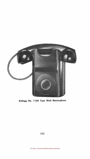
Kellogg No. 1100 Type Wall Masterphone
viii

TCI Library - http://www.telephonecollectors.info/inbox
Kellogg No. 0-1100 Type Wall Masterphone
ix

TCI Library - http://www.telephonecollectors.info/inbox
SECTION I
INSTALLATION
1

TCI Library - http://www.telephonecollectors.info/inbox
2
SECTION I - INSTALLATIONGENERAL
The Kellogg No. 1000 Series desk type or No. 1100 Serieswall type Masterphones are designed for common batteryservice but may be adapted for local battery service. Allparts such as switch-hook, condenser, ringer and inductioncoil are mounted on one base assembly (see figure 1).
Figure 1 - Base Assembly
The Masterphone is adjusted to operate under normal lineconditions before leaving the Kellogg Factory.
© Kellogg Switchboard & Supply Co., 1947

TCI Library - http://www.telephonecollectors.info/inbox
There are three adjustable links (see figure 2), which maybe modified to adapt the telephone to particular requirements. They are as follows:
Link No.1 is for changing the ringer circuit from metallicto divided (grounded) ringing (see figure 3).
LhR .1~ 70 acljwsf !'orcI/v/cleci or melgille; ringing.
L/nR 2 ~ 70 attiC/sf .,corslJorf~ medi'um~ or lonf! /00/'
L/n!? 3 - To acljt/sfposH/on Tor 05 or /.0 ml!
Figure 2 - Adjustable Links
Link No.2 (figure 4) is for adjustment of the transmittercircuit to adapt it to a long or short loop (distance in ohmsfor central office) .
Link No.3 has two taps which adapt the condenser capaci-
3
© Kellogg Switchboard & Supply Co., 1947

TCI Library - http://www.telephonecollectors.info/inbox
4
ties to match the various type ringers used with these sets(see figure 5).
Metallic Divided
Figure 3 - link No. 1
All common battery telephones are shipped from theKellogg factory with the three links arranged for the following conditions:
Link No. I-For metallic ringingLink No.2-For long loop conditions
© Kellogg Switchboard & Supply Co., 1947

TCI Library - http://www.telephonecollectors.info/inbox
Link No.3-For condenser capacity to match ringer furnished ~ith telephone (for example, 16 cycle, 1 mf.; 16%cycle, 1 mf.; 50 cycle,.5 mf.).
Short Medium
Figure 4 - Link No. 2
Long
INSTALLATION PROCEDURE
No. I-Determine frequency of ringer to be used (either16,16%,20,25 cycle and so forth).
No.2-Determine whether metallic or divided (grounded)ringing connection is required.
No.3-Determine whether distance from central officewill require a long or short loop connection.
5
© Kellogg Switchboard & Supply Co., 1947

TCI Library - http://www.telephonecollectors.info/inbox
6
No.4-Refer to Charts No. 1, No. 2 and No. 3 for correctlink connections.
No.5-Make changes in link connections when necessaryas determined from charts. (Charts No.1, No.2 and No.3follow on pages 8, 9 and 10.)
1.0 mf. 0.5 mf.
Figure 5 - Link No. 3
EXAMPLE USE OF CHARTS
This example provides for the installation of a commonbattery telephone equipped with a 42 cycle ringer, dividedringing, with a long loop connection.
Refer to Chart No. 142 cycle (Column A). Divided ringing(Column B). We find the position of Link No.1 should beon "D" position (Column C). Link No.2 in position 2 or 3and Link No. ain position marked.5 mf.
The~~me procedure should be followed for various cycleringers as shown on this chart for common battery service.
© Kellogg Switchboard & Supply Co" 1947

TCI Library - http://www.telephonecollectors.info/inbox
This procedure applies to Chart No.2 except that the location of the No.2 link is always in the No.1 position.
NOTE: See note under charts 1 and 2 for divided ringing.
NOTE: See chart 3 for common and local battery sets usingdesk set boxes (old style with ringer, condenser and induction coil).
7
© Kellogg Switchboard & Supply Co .• 1947

TCI Library - http://www.telephonecollectors.info/inbox
8
Common Battery (Combined Sets Only)CHART 1
Pri nt No. 21258
cyc:e of 1- Ty:e of 1Position of 1- POsiiion-~ link 20 --1 Position of
Ringer Ringiog link 1 . Shut loop I long loop link 3
f6 I Metallic I M 1 2 or 3 I 1 mf.16 Divided D 1 2 or 3 \ 1 mI.162/3 1 Metallic 1 MIn2 or 3 1 1 mf.162j3 I Divided I D 1 2 or 3 I 1 mf.20 I Metallic I MIl 2 or 3 I 1mf.20 I Divided I D 1 1 I 2 or 3 1 mI.BA & SA 1 MefiillcT-M '~-I--I--I-2 or 3 1.5 mI. or 1 mI.BA I Divided I D I 1 I 2 or 3 1·5 mf. or 1mI.-BB-&SB-I-Meblllcl~M-I~I---1 -far3-1 1 mf.
BB I Divided I D \ 1 I 2 or 3 \ 1 mI.-13-cTSC-IMeEillicl-M~ 11--1--1- 2or3 1 1mI.
BC I Divided I D 1 I 2 or 3 I 1 mf.25 I Metallic 1--Mil \ 2 or 3 I .5 mI.25 1 Divided I D I 1 I 2 or 3 I .5 mI.
-30--I--Metallic-
1--M---
1
1-I-- \ 20r3-\- .5ml-.-30 I Divided I D 1 1 2 or 3 \ .5 mf.
-331/-3-1 Metallic I Muul --I-\-20r3 1-.5mr.-33113 I Divided I D I 1 1 2 or 3 I .5 mf.
42 - --I-Metallic I M-\--I--I-2 or 3-1--.5mC--42 I Divided I D I 1 I 2 or 3 I .5 mf.
-~~-~I-~i~l~'~fl~~-1 t -I-~~~~-I-:E~r--54 \ Metalllc-I-M- II 1 --\--2 or 3-1- .5 mC-54 I Divided I D 1 2 or 3 I .5 mI.
-60---I-M-etallic I M-11--I--1-2or3-1u-:-5~
60 I Divided I D 1 I 2 or 3 1 .5 mI.-66~~1 Metallic I M II 1 1 2m3-1--.5~
66 I Divided I D 1 I 2 or 3 I .5 mf.662/3 I Metallicl~M--I--I- -1--2 or3-1--.5~66% I Divided I D I 1 I 2 or 3 I .5 mf.
NOTE: For divided ringing a three (3) conductor cord must be used.*Using Code No. 113-A Induction Coil.
© 1<~llc99 Switchboord & Supply Co., 1947

TCI Library - http://www.telephonecollectors.info/inbox
A
Magneto (Local Battery), or Common BatterySignalling and Local Battery Talking
(Combined Sets Only)CHART 2
Print No. 21258
I. I 0 IC,cle .f T,pe 01 Posillon 01 Pasilian 01 Polillan 01Rinre, Ringinr link 1 link 2' link 3
f6 I Metallic M II 1 11 1 mf.16 Divided D 1 1 mi.16213 I Metallic M II 1 I' 1 mi.162/ 3 Divided D 1 1 mf.20 I Metallic Mil I 1 mf.20 Divided D 1 1 mi.BA & SA I Metallic M II 1 1.5 mi. or 1 mi.BA Divided D 1.5mi. or 1 mi.SB & SB II Metallic M _II 1 I 1 mi.BB Divided D 1 I 1 mf.BC & SC I Metallic --M-- I 1 I 1 mi.BC I Divided D 1 I 1 mi.25 I Metallic -.-Mil I .5 mi.25 Divided 1 D 1'.5mf.
-30'--II~I-iC-I--M---I--1--1 .5 mi.30 Divided D 1 .5 mi.331/3 I Metallic I Mil I .5 mf.33113 Divided I D 1 I .5 mi.42 I Metallic I Mil I .5 mf.42 Divided D 1 I .5 mi.50 I Metallic , Mil I .5 mi.50 Divided I D I 1 I .5 mi.54 I Metallic I Mil I .5 mi.54 Divided D 1 .5 mi.60 I Metallic I Mil I .5 mi.60 Divided I D 1 .5 mf.66 I Metallic I Mil I .5 mi.66 Divided I D I 1 I .5 mi.66% I Metallic I Mil I .5 mf.661/3 Divided D 1 .5 mf.
NOTE: For divided ringing a three (3) conductor cord must be used.*Using Code No. 114-A Induction Coil.
9
© Kellogg Swilchboord & Supply Co., 1947

TCI Library - http://www.telephonecollectors.info/inbox
10
Common BaHery and Local BaHeryUsing Desk Set Boxes (Old style with ringer,
condenser and induction coil)CHART 3
Print No. 21260
A B C D
IE
Cycle Type POliti on Position Position01 of 'f of 01
Ringer Ringing link 1 Link 2 I Link 3
Does notapply
Does notapply
Not used IShOr\ Loop I Long1Loop Not used
© Kellogg Switchboord & Supply Co., 1947

TCI Library - http://www.telephonecollectors.info/inbox
To Remove Housing on No.1 000 andNo. 1100 Series Masterphones
Desk Masterphones (1000 Series)
Back out screw recessed in the front end of the base plateas illustrated in figure 6. Swing housing upward away fromthe base plate and then disengage from the projection located at the rear end of the base plate (see figure 7). Re-
Figure 6 - Loosening Housing Screw
11
© Kellogg Switchboard & Supply Co., 1947

TCI Library - http://www.telephonecollectors.info/inbox
12
move the 'dial plug from the interconnecting block (figure
8) on dial telephones and the Press- to-Talk leads on Press-
figure 7 - Removing Desk Housing
© Kellogg Switchboard & Supply Co., 1947

TCI Library - http://www.telephonecollectors.info/inbox
to-Talk telephones. The housing is then completely disconnected and may be set aside. On manual telephones no circuit disconnections are required for this operation.
Figure 8 - Removing Dial Plug
13
© Kellogg Switc!lboord & Supply Co., 1947

TCI Library - http://www.telephonecollectors.info/inbox
14
Wall Masterphones (J 100 Series)
To remove housing pull the proj ection (figure 9) locatedbetween the sound holes on the bottom of the housing forward until the catch disengages the base plate and the lower
Figure 9 - Pulling Housing Projection
© Kellogg Switchboard & Supply Co., 1947

TCI Library - http://www.telephonecollectors.info/inbox
part of the housing can be moved away from the base plate.With the top as a hinge, swing the housing upwards untilthe housing is disengaged from the base plate projection(see figU1'e 10).
Figure 10 - Removing Wall Housing
Remove the dial plug from the interconnecting block ondial telephones (figure 8) and the Press-to-Talk leads onPress-to-Talk telephones. The housing is then completelydisconnected and may be set aside. On manual telephonesno circuit disconnections are required for this operation.
15
© Kellogg Switchboard & Supply Co., 1947

TCI Library - http://www.telephonecollectors.info/inbox
IG
Assembling Housing on No. 1000 and
No. 1100 Series Masterphones
Desk Masterphones (J 000 Series)Be sure that all parts previously disconnected have been
properly reconnected and cords and wiring dressed withinthe instrument to avoid interference with moving parts.
Step I-Invert the housing and base plate.
Step 2-Hold base plate at a slight angle so that the ringergongs do n:>t strike the housing.
Step 3-Slide the base plate so the projecting ear entersthe opening in the housing catch.
Step 4-Locate the line and handset cord in openings provided and close set.
Step 5-Engage screw and tighten with a screw driver.
Wall Masterphones (J J00 Series)
Before replacing the housing check that all parts previously disconnected have been properly reconnected. Cordsand wiring should be dressed within the instrument to avoidinterference with moving parts.
Step I-Place the base plate in a vertical position.
Step 2---Hold the housing at a slight angle so that it clearsthe ringer gongs.
Step 3-Center the top of the housing uver and above thetop side of the base plate assembly.
Step 4-Move the housing downward until the projectingear of the base enters the opening in the housing catch.
© Kellogg Switchboar~ & Supply Co., 1947

TCI Library - http://www.telephonecollectors.info/inbox
Step 5-Move the lower portion of the housing toward thebase plate. After contact apply sufficient pressure on thelower portion to engage the spring catch.
When the spring catch engages the base plate it will beaccompanied by a distinct "snap." Check by pulling forwardon the housing. When properly engaged it will be lockedsecurely at both top and bottom.
17
© Kellogg Switchboard & Supply Co., 1947

TCI Library - http://www.telephonecollectors.info/inbox
18
TESTS AFTER INSTALLATION
Talking and Listening Tests
In a normal tone of voice with the mouthpiece directly infront of and within one inch of the lips talk to the centraloffice operator, wire chief or other designated persons. Thetelephone should provide good transmission and receptionwith little side tone.
If side tone and transmission qualities (on common battery telephones only) are not as desired, move Link No.2(figure 4) to Position 1, 2 or 3, leaving it in the locationwhich provides the best transmission.
Ringing Tests, Precautions and Ad;ustments
Obtain a ring back over the line and check for properoperation of the ringer.
On bridged-selective ringing, observe that no other station bells operate on the assigned frequency of station beinginstalled.
© Kellogg Switchboard & Supply C~., 1947

TCI Library - http://www.telephonecollectors.info/inbox
On desk Masterphones connected for divided (grounded)ringing, where the ringer does not operate, reverse linewires (inside wires) L1 and L2 (figure 11) at the terminalblock at the junction of the cord and the inside wire.
Figure 11 - Reversing Line Wires on Terminal Block
19
© Kellogg Switchboard & Supply Co., 1947

TCI Library - http://www.telephonecollectors.info/inbox
20
For divided (grounded) ringing on wall Masterphoneswhere the ringer does not operate, reverse the line wires(inside wires Ll and L2 (fig1..~re 12) at the terminal block
on the base assembly.
Figure 12 - Reversing Line Wires on Base Assembly
When pulsating super-imposed ringing is used in con-
© Kellogg Switchboard & Supply Co., 1947

TCI Library - http://www.telephonecollectors.info/inbox
nection with the vacuum tube for station selection it willbe necessary to determine the correct connection for Line 1and Line 2 and the proper polarity of the ringers as well. Ifnecessary this may be done by reversing the Line 1 andLine 2 leads (figure 11), and the red and black leads of the
Figure 13 - Reversing Ringer Leads
ringer (figure 13). Another method would be to determinethe tip or ring of the line through use of a handset andconnect the side over which the telephone will be rung tothe L1 lead. The normal connection is the red wire from
21
© Kellogg Switchboard & Supply Co., 1947

TCI Library - http://www.telephonecollectors.info/inbox
22
the ringer connecting to Link No.3 (Rt) and the blackwire from the ringer to R2 (-) negative currents. When
the ringer leads are reversed (that is, the black wire of the
ringer Link No.3 (Rl) and red wire of ringer to Rz), theringer is connected for positive (+) currents.
If bell tapping occurs in dial telephones using biased
ringers, reverse the red and black ringer leads (see figure
13). Where it is found that reversing the ringer leads does
Figure 14 - Increasing Bias Tension
not correct the condition connect them for the least disturbing tapping and increase the bias tension (figure 14).
© Kellogg Switchboord & Supply Co., 1947

TCI Library - http://www.telephonecollectors.info/inbox
Bias tension should not be greater than necessary sinceexcessive tension affects the quality of the ring.
No corrective measures can be taken to prevent tappingwhen straight line (SA-SB-SC) ringers are used.
Figure 15 - Adjusting Ringer Gongs
If the ringer does not operate properly, minor adjust
ments can be made by loosening the gong mounting screwsslightly so that the gongs may be rotated until the desiredringing tone is obtained. Hold the gongs securely, tightenthe mounting screws (see figure 15) and retest for ringing
as the gong positions may have been altered during thetightening.
23
© Kellogg Switchboard & Supply Co., 1947

TCI Library - http://www.telephonecollectors.info/inbox
24
SECTION II
COMMON BATTERYMAINTENANCE
AND TROUBLE CLEARING
© Kellogg Swilchboord & Supply Co., 1947

TCI Library - http://www.telephonecollectors.info/inbox
SECTION 11- COMMON BATTERY
MAINTENANCE AND TROUBLE CLEARING
. GENERALA voltmeter test should be made on all lines on which a
subscriber's report of trouble has been received. A largenumber of troubles which affect the operation of stationequipment are found in other classes of plant associatedwith the subscriber's circuit. These troubles should becleared before the final test is made at the station.
As a rule trouble clearing at the subscriber's premisesshould be limited to those cases which can easily be corrected and repaired. When in doubt, replace the instrument.
25
© Kellogg Switchboard & Supply Co" 1947

TCI Library - http://www.telephonecollectors.info/inbox
26
REPORTED TROUBLE
Traced to Station Equipment
Remove the housing from the Masterphone so that thecomponent parts of the base assembly are accessible. Disconnect the interior wire on the wall Masterphone, or theline cord on the desk Masterphone (figure 16) from the L l'
Figure 16 - Disconnecting Line Leads
L2 and ground terminals on the connecting block, and againdetermine if the line is normal toward the central office. Ifthe line is clear, the trouble is likely to be in the telephoneinstrument.
© Kellogg Switchboard & Supply Co., 1947

TCI Library - http://www.telephonecollectors.info/inbox
Can't Be Heard
The following procedure will localize the fault. Test aftereach step before proceeding to the next one.
oFigure 17 - Replacing Transmitter
Step I-Replace the transmitter capsule with one knownto be good and determine that the mouthpiece is satisfactory(see figure 17).
Step 2-Check that Link 2 (figure 4) is in the correct
position for the station involved. Refer to Chart No. 1.
27
© Kellogg Switchboard & Supply Co., 1947

TCI Library - http://www.telephonecollectors.info/inbox
28
Step 3-Defective Induction Coil. Replace induction coil(Code No. 113A) with one known to be satisfactory (seefigure 18).
Figure 18 - Replacing Induction Coil
Step 4-Replace the complete telephone with one knownto be satisfactory. If this does not clear the fault rechecktoward the central office for other sources of trouble.
© Kellogg Switchboard & Supply Co., J 947

TCI Library - http://www.telephonecollectors.info/inbox
Can't Hear (Poor or No Reception)
The following procedure will localize the fault. Test aftereach step before proceeding to the next one.
Figure 19 - Replacing Receiver
Step I-Damaged receiver or ear cap. Replace the capsulewith one known to be good (figure 19). Be sure that proper
ear cap is used. The proper cap is one which screws flushwith the handset receiver recess.
29
© Kellogg Switchbo:Hd r. Supply C~., 1'747

TCI Library - http://www.telephonecollectors.info/inbox
30
Step 2-Defective condenser. Replace the condenser withone known to be good (see figure 20).
Step 3-Defective induction coil. Replace the inductioncoil (Code No. 113A) with one known to be good (see
figure 18).
Figure 20 - Replacing Condenser
Step 4-Replace the complete telephone with one knownto be satisfactory. If this does not clear the trouble rechecktoward the central office for other sources of trouble.
© Kellogg Switchboard & Supply Co., 1947

TCI Library - http://www.telephonecollectors.info/inbox
Intermittent Operation or Noises
This trouble is usually caused by loose assemblies, connections or broken wires and cords.
The following procedure will localize the fault. Test aftereach step before proceeding to the next one.
Step I-Bend and shake line <:nd handset cords. Move ortap the various circuit elements such as dial, condenser andinduction coil for loose connections. Check screws holdingthe links for tightness.
Step 2-Replace the complete telephone set with oneknown to be satisfactory. If this does not clear the fault,recheck toward the central office for other sources of trouble.
Ringer Trouble
Telephone ringer trouble may be caused by various conditions, but a very simple test will disclose the source. Besure and cl~eck that the proper frequency ringer is installed.Determine if Link 3 (figure 5) is in the correct position forthe ringer involved, and that Link 1 (figure 3) is connectedfor either metallic or divided (grounded) ringing as required. See Chart No. I.
All ringers are factory adjusted to operate on averagevoltages most commonly used. They are equipped with anadjustment screw to adjust air gaps between the armatureand the pole pieces. This adjustment is provided to compensate for various ringing voltages.
Bells Don" Ring-The following procedure will localizethe fault. Test after each step before proceeding to the nextone.
31
© Kellogg Switchboord 8. SUPf.l)' Co" 1947

TCI Library - http://www.telephonecollectors.info/inbox
32
Step I-Open condenser. Replace with one known to begood (see fig1iTe 20).
Figure 21 - Removir.g Ringer Screw
Step 2-Defective ringer. Replace ringer with one knownto be good, and of the correct frequency and resistance (seefigure 21).
Step 3-Replace the complete telephone with one knownto be satisfactory. If this does not clear the fault, rechecktoward th(-! central office for other sources of troublp.
© Kellogg Switchboard & Supply Co., 1947

TCI Library - http://www.telephonecollectors.info/inbox
Bells Ring Too Loud or
Bells Don't Ring Loud Enough-
Biased & Straight Line Ringers-The following procedurewill help localize the fault. Test after each step beforeproceeding to the next one.
Figure 22 - Adjusting Gong Spacing
Step I-Check the gong adjustment by holding first oneand then the other side of the armature against its respective pole piece (see figure 22).
33
© Kellogg Switchboard & Supply Co., 1947

TCI Library - http://www.telephonecollectors.info/inbox
34
Step 2-Adjust the space between the gong and the clapperto approximately %:! inch by rotating each gong about itsmounting screw until the desired spacing of ~32 inch isattained. Slight deviations from the ~32 inch spacing may bemade for louder or softer ringing.
Step 3-Adjust the tension on the biased ringers with aminimum amount of tension to prevent tapping (see figure23).
Figure 23 - Adjusting Tension on Biased Ringers
Step 4-Test the ringer and be sure that the clapper strikesboth gongs and gives a satisfactory ring.
Step 5-Replace the complete telephone with one knownto be satisfactory. If this does not clear the trouble, rechecktoward the central office for other sources of trouble.
© Kellogg Switchboard & Supply Co., 1947

TCI Library - http://www.telephonecollectors.info/inbox
Harmonic Ringers-Merely adjust the gong spacing forthe desired tone quality (see figure 22).
Bell Tapping-The following procedure will help to localize the fault. Test after each step before proceeding to thenext one.
Step l-Check code of ringer. If a straight line ringer isinstalled, replace with a biased ringer.
Figure 24 - Reversing Ringer Leads
Step 2-Reverse the ringer leads Rl and R2 on AC ringing systems (see figure 24) If this does not clear the troubleconnect the ringer for the least objectionable tapping andincrease the bias tension only to the point where bell tappingceases (see figure 23).
35
© Kellogg Switchboard & Supply Co" 1947

TCI Library - http://www.telephonecollectors.info/inbox
36
SECTION III
KELLOGG MASTER DIAL
© Kellogg Switchboard & Supply Co., 1947

TCI Library - http://www.telephonecollectors.info/inbox
SECTION III - KELLOGG MASTER DIALGENERAL
The Kellogg Master Dial has been properly adjusted aftermanufacture and should require a minimum of attention.The following servicing or adjusting may be performed bylocal repair or maintenance personnel if necessary.
(a) Dial Number Card(b) Lubrication(c) Spring Contacts
Kellogg Master Dial
DIAL NUMBER CARDThe dial number card is mounted under a circular trans
parent protector in a retaining ring. To change the dial number card, remove the card retaining ring by rotating it
37
© Kellogg Switchboard & Supply Co., 1947

TCI Library - http://www.telephonecollectors.info/inbox
38
approximately 15° in either direction (see figure 25). KelloggCode No. 86 Tool is available for removing and reassembling
Figure 25 - Removing Dial Number Card
the dial retaining ring. The dial number card and transparent protector are notched in order that they can be
© Kellogg Switchboard & Supply Co., 1947

TCI Library - http://www.telephonecollectors.info/inbox
inserted in one position only in the retaining ring (see fig
ure 26).
Figure 26 - Dial Card, Protector and Ring
To re-assemble, pla~ce the retaining ring assembly in thefinger plate recess approximately 15° from its normal vertical position and rotate the ring to the normal vertical position.
39
© Kellogg Switchboard & Supply Co., 1947

TCI Library - http://www.telephonecollectors.info/inbox
40
LUBRICATION
If the dial ever becomes dry or sluggish, lubricate the sixbearing points indicated in figures 27 and 28.
Pill/oil SlaTf' BecTr/0!1(rrom')
Figure 27 - Dial Lubrication Points (Front)
From the front of the dial, after removing the retainingring, number card, and the finger plate, the top main shaftbearing and top pinion staff bearing can be lubricated (seefigure 27).
From the rear of the dial, the lower main shaft bearing,
© Kellogg Switchboard & Supply Co., 1947

TCI Library - http://www.telephonecollectors.info/inbox
lower pinion staff bearing and the two governor shaft bearings can be lubricated (see figure 28).
Ph/on Sfal'!' 8ean'n.:!(Rear)
/1Iorm Shaf'l 8earin,ys/
Figure 28 - Dial Lubrication Points (Rearl
Apply a drop of Kellogg Special Dial Lubricant to each ofthe bearings by means of a small applicator or a piece ofclean bare wire approximately No. 20 B&S gauge. Caution:Use only Kellogg Special Dial Lubricant for this purpose.
41
© Kellogg Switchboard & Supply Co., 1947

TCI Library - http://www.telephonecollectors.info/inbox
42
SPRING CONTACTS
If the spring contacts are dirty or corroded use a KelloggNo. 68 Contact Burnisher to clean. Inserting the blade ofthe Burnisher between the two contacts and with normalspring pressure, burnish the contacts two or three times(see figure 29).
Figure 29 - Cleaning Spring Contact
It is recommended that any other adjustments be madeby a person familiar with the Master Dial maintenance,who has all the tools and equipment needed to adjust itproperly. Otherwise the dials should be returned to Kelloggfor repair and adjustment.
© Kellogg Switchboard & Supply Co., 1947

TCI Library - http://www.telephonecollectors.info/inbox