kc series gas fired water heating system -...
TRANSCRIPT

Printed in U.S.A. REVISED 12/10
AERCO International, Inc. • 159 Paris Ave. • Northvale, New Jersey 07647 • Phone: 201-768-2400 • FAX: 201-768-7789
KC Series Gas Fired Water Heater GF-111 OMM-xxxx-xx Operation and Maintenance Manual
Applicable to Serial Numbers G-02-530 and above KC Series Gas Fired Water Heating System
Natural Gas or Propane Fired, Condensing and Forced Draft Hot Water Heater
1,000,000 BTU/HR Input
Patent No. 4,852,524
Printed in U.S.A. REVISED JANUARY, 2009
AERCO International, Inc. • 159 Paris Ave. • Northvale, New Jersey 07647 • Phone: 201-768-2400 • FAX: 201-768-7789
KC Series Gas Fired Water Heater GF-111 OMM-xxxx_xx Operation and Maintenance Manual
Telephone Support Direct to AERCO Technical Support (8 to 5 pm EST, Monday through Friday) (800) 526-0288
AERCO International, Inc. 159 Paris Avenue Northvale, NJ 07647-0128 www.aerco.com © AERCO International, Inc., 2009 The information contained in this operation and m aintenance manual is subject to change without notice from AERCO International, Inc. AERCO makes no warranty of any kind with respect t o this material, i ncluding but not limited to implied warranties of merchantability and fitness for a particular application. AERCO International is not liable for errors appearing in this manual. Nor f or i ncidental or co nsequential damages occurring i n co nnection w ith t he furnishing, performance, or use of this material.

CONTENTS
i
GF-111 THE AERCO KC1000 GAS FIRED DOMESTIC WATER HEATER Operating & Maintenance Instructions
FOREWARD A
Section 1 – SAFETY PRECAUTIONS 1-1 Para. Subject Page 1.1 Warnings & Cautions 1-1 1.2 Emergency Shutdown 1-2
Para. Subject Page 1.3 Prolonged Shutdown 1-2
Section 2 – INSTALLATION PROCEDURES 2-1 Para. Subject Page 2.1 Receiving the Unit 2-1 2.2 Unpacking 2-1 2.3 Installation 2-2 2.4 Gas Supply Piping 2-4 2.5 Electrical Supply 2-5
Para. Subject Page 2.6 Field Control Wiring 2-6 2.7 Flue Gas Vent Installation 2-8 2.8 Combustion Air 2-8
Section 3 – CONTROL PANEL OPERATING PROCEDURES 3-1 Para. Subject Page 3.1 Introduction 3-1 3.2 Control Panel Description 3-1 3.3 Control Panel Menus 3-3 3.4 Operating Menu 3-4 3.5 Setup Menu 3-4
Para. Subject Page 3.6 Configuration Menu 3-6 3.7 Tuning Menu 3-7 3.8 Start Sequence 3-7 3.9 Start/Stop Levels 3-9
Section 4 – INITIAL START-UP 4-1 Para. Subject Page 4-1 Initial Startup Requirements 4-1 4-2 Tools and Instrumentation for
Combustion Calibration 4-1
4-3 Natural Gas Combustion Calibration
4-2
Para. Subject Page 4-4 Propane Combustion Calibration 4-5 4.5 Unit Reassembly 4-5 4.6 Temperature Control Calibration 4-6 4.7 Over-Temperature Limit Switch
Adjustments 4-7

CONTENTS
ii
Section 5 – SAFETY DEVICE TESTING PROCEDURES 5-1 Para. Subject Page 5.1 Testing of Safety Devices 5-1 5.2 Low Gas Pressure Fault Test 5-1 5.3 High Gas Pressure Test 5-1 5.4 Low Water Level Fault Test 5-2 5.5 Water Temperature Fault Test 5-2 5.6 Interlock Tests 5-3 5.7 Flame Fault Test 5-3 5.8 Air Flow Fault Test 5-4
Para. Subject Page 5.9 SSOV Proof of Closure Switch 5-4 5.10 Purge Switch Open During
Purge 5-5
5.11 Ignition Switch Open During Ignition
5-5
5.12 Safety Pressure Relief Valve Test
5-6
Section 6 – MAINTENANCE 6-1 Para. Subject Page 6.1 Maintenance Schedule 6-1 6.2 Spark Ignitor 6-1 6.3 Flame Detector 6-2 6.4 Combustion Calibration 6-2 6.5 Safety Device Testing 6-2 6.6 BTU Transmitter Pump
Lubrication 6-2
Para. Subject Page 6.7 BTU Transmitter Assembly 6-3 6.8 Manifold and Exhaust Tubes 6-5 6.9 Heat Exchanger Inspection 6-8 6.10 Condensate Drain Assembly 6-9
Section 7 – TROUBLESHOOTING 7-1 Para. Subject Page 7.1 Introduction 7-1
Para. Subject Page
APPENDICES App Subject Page A Water Heater Menu Item
Descriptions A-1
B Startup, Status and Fault Messages
B-1
C Temperature Sensor Resistance Chart
C-1
D Water Heater Default Settings D-1
App Subject Page E Dimensional and Parts Drawings E-1 F Piping Drawings F-1 G Wiring Schematics G-1 H KC1000 Control Panel Views H-1
WARRANTIES W-1
FOREWORD
A
Foreword The AERCO KC Water Heating System is a true industry advance that meets the needs of today's energy and environmental concerns. Designed for use in any potable water heating system, it provides constant temperature water, regardless of flow rate. It’s small space requirements and venting capabilities allow maximum installation flexibility. The KC Heater’s load tracking controls modulate over a 20:1 turndown ratio for natural gas units and a 14:1 turndown ratio for propane units to match fluctuating system loads and yield high thermal efficiencies. With it’s compact design and direct or chimney venting, the KC Water Heating System is adaptable to any installation. Efficiency, reliability and longevity make the KC Water Heating System a true step forward in Water Heating System design. After prolonged shutdown, it is recommended that the startup procedures in Section 4 and test procedures in Section 5 of this manual be performed to verify system operating parameters. If there is an emergency, turn off the electrical power supply to the KC Heater or close the manual gas valve located before the unit. The installer is to identify the emergency shut-off device. FOR SERVICE OR PARTS, contact your local sales representative or AERCO INTERNATIONAL. NAME: ORGANIZATION:
ADDRESS: TELEPHONE: INSTALLATION DATE: ____________________________________________________


SAFETY PRECAUTIONS
1-1
SECTION 1 -- SAFETY PRECAUTIONS
1.1 WARNINGS & CAUTIONS Installers and operating personnel MUST, at all times, observe all safety regulations. The following warnings and cautions are general and must be given the same attention as specific precautions included in these instructions. In addition to all the requirements included in this AERCO Instruction Manual, the installation of units MUST conform with local building codes, or, in the absence of local codes, ANSI Z223.1 (National Fuel Gas Code Publication No. NFPA-54) for gas-fired heaters and ANSI/NFPASB for LP gas-fired heaters. Where applicable, the equipment shall be installed in accordance with the current Installation Code for Gas Burning Appliances and Equipment, CGA B149, and applicable Provincial regulations for the class; which should be carefully followed in all cases. Authorities having jurisdiction should be consulted before installations are made.
IMPORTANT This Instruction Manual is an integral part of the product and must be maintained in legible condition. It must be given to the user by the installer and kept in a safe place for future reference.
WARNINGS! MUST BE OBSERVED TO PREVENT SERIOUS INJURY.
WARNING! BEFORE ATTEMPTING TO PERFORM ANY MAINTENANCE ON THE UNIT, SHUT OFF ALL GAS AND ELECTRICAL INPUTS TO THE UNIT.
WARNING DO NOT USE MATCHES, CANDLES, FLAMES, OR OTHER SOURCES OF IGNITION TO CHECK FOR GAS LEAKS.
WARNING! THE EXHAUST VENT PIPE OF THE UNIT OPERATES UNDER A POSITIVE PRESSURE AND THERE-FORE MUST BE COMPLETELY SEALED TO PREVENT LEAKAGE OF COMBUSTION PRODUCTS INTO LIVING SPACES.
WARNING! FLUIDS UNDER PRESSURE MAY CAUSE INJURY TO PERSONNEL OR DAMAGE TO EQUIPMENT WHEN RELEASED. BE SURE TO SHUT OFF ALL INCOMING AND OUTGOING WATER SHUTOFF VALVES. CAREFULLY DECREASE ALL TRAPPED PRESSURES TO ZERO BEFORE PERFORMING MAINTENANCE.
WARNING! ELECTRICAL VOLTAGES OF 120 VAC ARE USED IN THIS EQUIP-MENT. THEREFORE THE COVER ON THE UNIT’S POWER BOX (LOCATED ON THE FRONT RIGHT SIDE OF THE UNIT UNDER THE HOOD AND SHEET METAL SIDE PANEL) MUST BE INSTALLED AT ALL TIMES, EXCEPT DURING MAINTENANCE AND SERVICING.
CAUTIONS! Must be observed to prevent equip-ment damage or loss of operating effectiveness.
CAUTION! Many soaps used for gas pipe leak testing are corrosive to metals. The piping must
CAUTION!
be rinsed thoroughly with clean water after leak checks have been completed.
DO NOT use this heater if any part has been under water. Call a qualified service technician to inspect and replace any part that has been under water.

SAFETY PRECAUTIONS
1-2
1.2 EMERGENCY SHUTDOWN If overheating occurs or the gas supply fails to shut off, close the manual gas shutoff valve (Figure 1-1) located external to the unit.
IMPORTANT The Installer must identify and indicate the location of the emergency shutdown manual gas valve to operating personnel.
1.3 PROLONGED SHUTDOWN After prolonged shutdown, it is recommended that the startup procedures in Chapter 4 and the safety device test procedures in Chapter 5 of this manual be performed, to verify all system-operating parameters. If there is an emergency, turn off the electrical power supply to the AERCO heater and close the manual gas valve located upstream the unit. The installer must identify the emergency shut-off device.
MANUAL GAS SHUTOFF VALVE
VALVE OPEN VALVE CLOSED
Figure 1-1
Manual Gas Shutoff Valve

INSTALLATION
2-1
SECTION 2 - INSTALLATION 2.1 RECEIVING THE UNIT Each KC1000 Heater is shipped as a single crated unit. The unit shipping weight is approxi-mately 1500 lb. and must be moved with the proper rigging equipment for safety and to avoid damage. The unit should be completely inspected at the time of receipt from the carrier before the bill of lading is signed. Each unit has Tip-N-Tell indicator on the outside of the crate. This indicates if the unit has been turned on its side.
If the Tip-N-Tell indicator is tripped, do not sign for the shipment. Note the information on the carrier’s paperwork and request a freight claim and inspection by a claims adjuster before proceeding. Any other visual damage to the packaging materials should also be made clear to the delivering carrier.
2.2 UNPACKING Carefully unpack the unit. Take care not to damage the unit jacket when cutting away packaging materials. A close inspection of the unit should be made to determine if there has been any damage incurred during shipment that was not indicated by the Tip-N-Tell indicator.
The freight carrier should be notified immediately if any damage is detected. The following acces-sories come standard with each unit and are packed separately within the unit’s packing con-tainer • Spare Spark Ignitor • Spare Flame Detector • Manual 1-1/4" Gas Shutoff Valve • Drain Valve Assembly • ASME Pressure/Temperature Relief Valve • Ignitor Removal Tool (1 per Site) • Regulator Adjustment Tool (1 per Site) • 2 Lifting Lugs • Stainless Steel Condensate Cup • Flue Clamps (2 Pieces) • Shell Cap • Wing nut for shell cap Optional accessories are also separately packed within the unit’s packing container. Standard and optional accessories shipped with the unit should be identified and put in a safe place until installation/use.
Figure 2.1 Heater Clearance

INSTALLATION
2-2
2.3 INSTALLATION The unit must be installed with the prescribed clearances for service as shown in Fig 2.1 These are the minimum
clearance dimensions required by AERCO. Local building codes may require more clearance and take precedence.
KEEP UNIT AREA CLEAR AND FREE FROM COMBUSTIBLE MATERIALS AND FLAMMABLE VAPORS AND LIQUIDS.
WARNING !
2.3.1 SETTING THE UNIT Locate the lifting lugs, shipped with the unit, and attach them to the 5/8” x 11 studs at the top of the unit. Remove the unit from the wooden skid and place in position using a block and tackle or hoist attached to the lifting lugs. (see Fig. 2.2). USE THE LIFTING LUGS TO MOVE THE UNIT. The KC-1000 is U/L approved for installation on combustible flooring. A 4” to 6" high housekeep-ing concrete pad is recommended and allows for sufficient drainage of the condensate. The unit must be secured using only the holes provided in the frame base. Do not use piping to secure the unit in place. See drawing AP-A-576 in Appendix E for the base frame dimensions. In multiple unit installations, it is important to plan the position of each unit. Sufficient space for piping connections and maintenance require-ments must be given. All piping must include ample provision for expansion.
Figure 2.2 Lifting Lug Location
2.3.2 WATER INLET AND OUTLET PIPING The locations of the 2" NPT cold water inlet and hot water outlet piping connections are shown in Figure 2.3. Flow rates through the unit are limited to 30 gpm continuous and 40 gpm intermittent. Shut-off valves and union conections must be installed in the inlet and outlet lines for maintenance. The use of dielectric unions is recommended. Install the piping and accesso-ries as per the following drawings, located in Appendix F of this manual. • SD-A-424 for single units • SD-A-425 for multiple units • SD-A-432 for single units with a stratified tank • SD-A-434 for multiple units with a stratified storage tank
NOTE: All piping must be arranged so that it does not interfere with removal of any cover, inhibit service or maintenance, or prevent access between the unit and walls, or another unit.
Figure 2.3 Inlet and Outlet Location

INSTALLATION
2-3
2.3.3 TEST HOSE BIB A Test Hose Bib connection, upstream of the shut off valve on the hot water outlet, is required for startup and testing. It should be a minimum of 3/4". It cannot be omitted (See Fig. 2.4a)
Figure 2.4a
Hose Bib Location 2.3.4 PRESSURE/TEMPERATURE RELIEF AND DRAIN VALVE INSTALLATION An ASME rated Pressure/Temperature Relief Valve is supplied with each unit. The valve setpoint is 150 psig/210°F. Install the relief valve as shown in Fig. 2.4b. A suitable pipe compound should be used on the threaded connections. Any excess should be wiped off to avoid getting any into the valve body. The relief valve should be pipied to within 12 inches of the floor to prevent injury in the event of a discharge. The relief piping must be full size, 1-1/2”, without reduction. No valves, restrictions, or other blockages are allowed in the discharge line. In multiple unit installations the discharge lines must not
be manifolded together. Each must be individually run to a suitable discharge location.
A 1” drain valve assembly is furnished with each unit. The assembly should be installed as shown in Figure 2.4b. The drain should be hard piped to a suitable drain. 2.3.5 SYSTEM RECIRCULATION The system recirculating line ties into the unit at the recirculating tee fitting provided in the drain valve assembly (see Fig. 2.4b). Shut off valves
and union connections are recommended for maintenance. Recirculation flow rates must be kept to 8 gpm or less. In a multiple unit installation, each unit must be tied into the system recirculation system.
Figure 2.4b Pressure/Temperature Relief and Drain
Valve Installation Location
2.3.6 CONDENSATE PIPING The KC Heater is designed to condense. Therefore, the installation site must include suitable provisions for condensate drainage or collection. A stainless steel condensate cup is separately packed within unit’s shipping container. To install the condensate cup, proceed as follows:
1. Remove the left side panel and only the left half of the rear cover to provide access to the exhaust manifold and burner (Figure 2.5).
2. Insert the 1-3/4 inch manifold drain hose into the condensate cup. Allow the cup to rest on the floor directly beneath the manifold drain hole (Figure 2.5).
3. Attach a length of 3/4 inch I.D. polypropylene tubing to the condensate cup drain tube and route it to a floor drain. . If a floor drain is not available, a condensate pump can be used to remove the condensate to drain. The condensate drain line must be removable for routine maintenance. Therefore, DO NOT hard-pipe.
4. Replace the rear cover and side panel on the unit.

INSTALLATION
2-4
TEMPERATURE SENSOR
EXHAUSTMANIFOLD
CONDENSATEDRAIN
BURNER
HOSE CLAMP
1-3/4" O.D. x 8-1 /2 “ LG.SILICONE HOSE
5/8" O.D. TUBE CONN.
CONDENSATE CUPPLACED ON FLOOR
Figure 2.5 Condensate Drain Assembly Location
2.4 GAS SUPPLY PIPING AERCO Gas Fired Equipment Gas Components and Supply Design Guide (GF-1030) should be consulted before any gas piping is designed or started.
WARNING ! DO NOT USE MATCHES, CANDLES, FLAMES OR OTHER SOURCES OF IGNITION TO CHECK FOR GAS LEAKS.
CAUTION ! Many soaps used for gas pipe leak testing are corrosive to metals. The piping must be rinsed thoroughly with clean water after leak checks have been completed.
NOTE: All gas piping must be arranged so that it does not interfere with removal of any cover, inhibit service or maintenance, or prevent access between the unit and walls, or another unit. The location of the 1-1/4" inlet gas connection on the right side of the unit is shown in Figure 2.6.
Figure 2.6 Gas Supply Regulator and Manual Shut -
Off Valve Location All pipe should be de-burred and internally cleared of any scale or iron chips before installation. No flexible connectors or non-approved gas fittings should be installed. Piping should be supported from floor or walls only and must not be secured to the unit. A suitable piping compound approved for use with gas should be used sparingly. Any excess must be wiped off to prevent clogging of components. To avoid damage to the unit when pressure testing gas piping, isolate the unit from the gas supply piping. At no time should there be more than 1 psig maximum to the unit. Bubble test all external piping thoroughly for leaks using a soap and water solution or suitable equivalent. The gas piping must meet all applicable codes.
2.4.1 GAS SUPPLY PRESSURE REGULATOR A mandatory external, in line, supply gas regu-lator (supplied by others) should be positioned as shown in Figure 2.6. Union connections should be placed in the proper locations to allow maintenance of the regulator if required.

INSTALLATION
2-5
NOTE: An individual gas pressure regulator must be installed upstream of each unit. The regulator must regulate gas pressure to 8.5” W.C. for FM gas train and 8.9” W.C. for IRI gas trains at 1,000,000 BTU/H for natural gas and propane units. The maximum static inlet pressure to the unit must not exceed 14” W.C. Minimum gas pressure is 8.5” W.C. for FM gas trains and 8.9” W.C. IRI gas trains when the unit is firing at maximum input. Gas pressure should not exceed 10.5” W.C. at any time when the unit is firing. Proper sizing of the gas supply regulator in delivering the correct gas flow and outlet pressure is mandatory. The gas supply pressure regulator must maintain the gas pressure at a minimum of 8.5” W.C. (FM) or 8.9” W.C. (IRI) when the unit is at maximum BTU input (1,000,000 BTU/HR). The supply gas regulator must be able to supply sufficient capacity volume, (1000 cfh), to the unit and should have no more than 1" droop from minimum to full fire. The supply gas regulator must also be rated to handle the maximum incoming gas pressure. When the gas supply pressure will not exceed 14” W.C. a non-lock up, or flow through style regulator, may be used. When supply gas pressure will exceed 14” W.C., a lock up style regulator must be used. The gas supply regulator must be propery vented to outdoors. Consult the local gas utility for exact requirements concerning venting of supply gas regulators.
CAUTION! A lockup style regulator must be used when gas supply pressure exceeds 14” W.C.
2.4.2 MANUAL GAS SHUTOFF VALVE A 1-1/4” manual gas shutoff valve is furnished with each unit and should be positioned as shown in Figure 2.6. The valve must be installed upstream of the gas supply regulator in a readily accessible location.
2.4.3 IRI GAS TRAIN KIT The IRI gas train is an optional gas train required in some areas by code or for insurance pur-poses. The IRI gas train comes pre-assembled and wired from the factory. See Appendix E, Drawing SD-A-606.
The IRI gas train may be ordered pre-assembled or as separate components. If either IRI gas train option is ordered a complete instructional package, detailing field installation will be included. To obtain a copy of an IRI instructional package prior to the equipment shipping contact your local representative or AERCO.
2.5 ELECTRICAL SUPPLY The AERCO Gas Fired Equipment Electrical Power Wiring Guide, (GF-1060), must be consulted in addition to the following material before wiring to the unit is started. AC power connection to the unit are made at the Power Box.This box is located on the front right side of the unit as shown in Figure 2.7.
POWER BOX
BLOWERSSOVACTUATOR
FRAME
Figure 2.7 AC Power Box Location
NOTE: All electrical conduit and hardware should be installed so that it does not interfere with the removal of any cover, inhibit service or maintenance, or prevent access between the unit and walls or another unit.
INSTALLATION
2-6
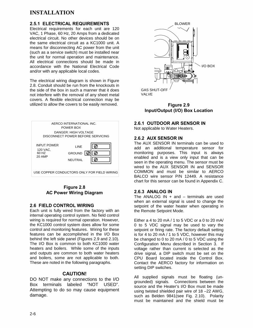
2.5.1 ELECTRICAL REQUIREMENTS Electrical requirements for each unit are 120 VAC, 1 Phase, 60 Hz, 20 Amps from a dedicated electrical circuit. No other devices should be on the same electrical circuit as a KC1000 unit. A means for disconnecting AC power from the unit (such as a service switch) must be installed near the unit for normal operation and maintenance. All electrical connections should be made in accordance with the National Electrical Code and/or with any applicable local codes. The electrical wiring diagram is shown in Figure 2.8. Conduit should be run from the knockouts in the side of the box in such a manner that it does not interfere with the removal of any sheet metal covers. A flexible electrical connection may be utilized to allow the covers to be easily removed.
USE COPPER CONDUCTORS ONLY FOR FIELD WIRING
60 HZ
DISCONNECT POWER BEFORE SERVICINGDANGER: HIGH VOLTAGE
20 AMP
120 VAC,
NEUTRAL
GROUND
LINE
POWER BOXAERCO INTERNATIONAL INC.
INPUT POWER
Figure 2.8
AC Power Wiring Diagram 2.6 FIELD CONTROL WIRING Each unit is fully wired from the factory with an internal operating control system. No field control wiring is required for normal operation. However, the KC1000 control system does allow for some control and monitoring features. Wiring for these features can be accomplished in the I/O Box behind the left side panel (Figures 2.9 and 2.10). The I/O Box is common to both KC1000 water heaters and boilers. While some of the inputs and outputs are common to both water heaters and boilers, some are not applicable to both. These are noted in the following paragraphs.
CAUTION! DO NOT make any connections to the I/O Box terminals labeled “NOT USED”. Attempting to do so may cause equipment damage.
GAS SHUT-OFFVALVE
I/O BOX
BLOWER
Figure 2.9 Input/Output (I/O) Box Location
2.6.1 OUTDOOR AIR SENSOR IN Not applicable to Water Heaters. 2.6.2 AUX SENSOR IN The AUX SENSOR IN terminals can be used to add an additional temperature sensor for monitoring purposes. This input is always enabled and is a view only input that can be seen in the operating menu. The sensor must be wired to the AUX SENSOR IN and SENSOR COMMON and must be similar to AERCO BALCO wire sensor P/N 12449. A resistance chart for this sensor can be found in Appendix C. 2.6.3 ANALOG IN The ANALOG IN + and – terminals are used when an external signal is used to change the setpoint of the water heater when operating in the Remote Setpoint Mode. Either a 4 to 20 mA / 1 to 5 VDC or a 0 to 20 mA/ 0 to 5 VDC signal may be used to vary the setpoint or firing rate. The factory default setting is for 4 to 20 mA / 1 to 5 VDC, however this may be changed to 0 to 20 mA / 0 to 5 VDC using the Configuration Menu described in Section 3. If voltage rather than current is selected as the drive signal, a DIP switch must be set on the CPU Board located inside the Control Box. Contact the AERCO factory for information on setting DIP switches. All supplied signals must be floating (un-grounded) signals. Connections between the source and the Heater’s I/O Box must be made using twisted shielded pair wire of 18 –22 AWG, such as Belden 9841(see Fig. 2.10). Polarity must be maintained and the shield must be

INSTALLATION
2-7
connected only at the source end. It must be left floating (not connected) at the Heater’s I/O Box. Whether using voltage or current for the drive signal, they are linearly mapped to a 40°F to 240°F setpoint or a 0% to 100% firing rate. No scaling for these signals is provided 2.6.4 B.M.S. (PWM) IN Not applicable to Water Heaters. 2.6.5 SHIELD The SHIELD terminals are used to terminate any shields used on sensor wires connected to the unit. Shields must only be connected to these terminals. 2.6.6 mA OUT These terminals provide a 4 to 20 mA output that can be used to monitor setpoint ( to 220°F), outlet temperature (
to 245°F), or fire rate (0% to 100%). This function is enabled in the Configuration Menu (Section 3, Table 3.4).
2.6.7 RS-485 COMM These terminals are used for RS-485 MODBUS serial communication between the unit and an external “Master”, such as an Energy Manage-ment System. 2.6.8 EXHAUST SWITCH IN These terminals permit an external exhaust switch to be connected to the exhaust manifold of the boiler. The exhaust sensor should be a normally open type switch (such as AERCO P/N 123463) that closes (trips) at 500°F. 2.6.9 INTERLOCKS The unit offers two interlock circuits for interfacing with Energy Management Systems and auxiliary equipment such as pumps or louvers or other accessories. These interlocks are called the Remote Interlock and Delayed Interlock (Fig. 2.10). The wiring terminals for these interlocks are located inside the I/O Box on the left side of the unit. The I/O Box cover contains a wiring diagram which shows the terminal strip locations for these interlocks labeled REMOTE INTL’K IN and DELAYED INTL’K IN. Both interlocks, described below, are factory wired in the closed position.
NOTE: Both the Delayed Interlock and Remote Interlock must be in the closed position to allow the unit to fire.
2.6.9.1 REMOTE INTERLOCK IN The remote interlock circuit (REMOTE INTL’K IN) is provided to remotely start (enable) and stop (disable) the unit if desired. The circuit is 24 VAC and comes factory pre-wired closed (jumped). 2.6.9.2 DELAYED INTERLOCK The delayed interlock circuit (DELAYED INTL’K IN) is typically used in conjunction with the auxiliary relay described in paragraph 2.6.11. This interlock circuit is located in the purge section of the start string. It can be connected to the proving device (end switch, flow switch etc.) of an auxiliary piece of equipment started by the unit’s auxiliary relay. The delayed interlock must be closed for the heater to fire. If the delayed interlock is connected to a proving device that requires time to close (make), a time delay (Aux Start On Dly) that holds the start sequence of the unit long enough for a proving switch to make (close) can be programmed. Should the proving switch not prove within the programmed time frame, the unit will shut down. The Aux Start On Dly can be programmed from 0 to 120 seconds. This option is locate in the Configuration Menu (Section 3). 2.6.10 FAULT RELAY The fault relay is a single pole double throw (SPDT) relay having a normally open and normally closed set of relay contacts that are rated for 5 amps at 120 VAC and 5 amps at 30 VDC. The relay energizes when any fault condi-tion occurs and remains energized until the fault is cleared and the CLEAR button is depressed. The fault relay connections are shown in Figure 2.10. 2.6.11 AUXILIARY RELAY CONTACTS Each unit is equipped with a single pole double throw (SPDT) relay that is energized when there is a demand for heat and de-energized after the demand for heat is satisfied. The relay is pro-vided for the control of auxiliary equipment, such as pumps and louvers, or can be used as a unit status indictor (firing or not firing). Its contacts are rated for 120 VAC @ 5 amps. Refer to Figure 2.10 to locate the AUX RELAY terminals for wiring connections.

INSTALLATION
2-8
mA OUT
RS-485COMM.
+
-
+-
ANALOG IN
SENSOR COMMONOUTDOOR SENSOR IN REMOTE INTL'K IN
B.M.S. (PWM) IN
SHIELD
+-
+-
AUX SENSOR IN
NOT USED
EXHAUST SWITCH IN
DELAYED INTL'K IN
FAULT RELAY120 VAC, 5A, RES
AUX RELAY120 VAC, 5A, RES
G
RELAY CONTACTS:120 VAC, 30 VDC5 AMPS RESISTIVE
DANGER120 VAC USED
IN THIS BOX
NOT USED NOT USEDNCCOMNO
NCCOMNO
NOT USED
Figure 2.10 I/O Box Wiring
2.7 FLUE GAS VENT INSTALLATION AERCO Gas Fired Venting and Combustion Air Guide, GF-1050, must be consulted before any flue or combustion air venting is designed or installed. Suitable, U/L approved, positive pressure, watertight vent materials MUST be used for safety and UL certification. Because the unit is capable of discharging low temperature exhaust gases, the flue must be pitched back towards the unit a minimum of 1/4" per foot to avoid any condensate pooling and to allow for proper drainage. While there is a positive flue pressure during operation, the combined pressure drop of vent and combustion air systems must not exceed 140 equivalent feet of 0.81” W.C. Fittings as well as pipe lengths must be calculated as part of the equivalent length. For a natural draft installation the draft must not exceed - 0.25” W.C. These factors must be planned into the vent installation. If the maximum allowable equivalent lengths of piping are exceeded, the unit will not operate properly or reliably.
2.8 COMBUSTION AIR The AERCO Gas-Fired Heater Venting and Combustion Air Guide, GF-1050 MUST be consulted before any flue or inlet air venting is designed or installed. Air supply is a direct requirement of ANSI 223.1, NFPA-54, and local codes. These codes should be consulted before a permanent design is determined. The combustion air must be free of chlorine, halogenated hydrocarbons or other chemicals that can become hazardous when used in gas-fired equipment. Common sources of these compounds are swimming pools, degreasing compounds, plastic processing, and refrigerants. Whenever the environment contains these types of chemicals, combustion air MUST be supplied from a clean area outdoors for the protection and longevity of the equipment and warranty validation. The more common methods of combustion air supply are outlined in the following paragraphs. For combustion air supply from ducting, consult AERCO GF-1050, Gas Fired Venting and Combustion Air Guide.

INSTALLATION
2-9
2.8.1 COMBUSTION AIR FROM OUTSIDE THE BUILDING Air supplied from outside the building must be provided through two permanent openings. For each unit these two openings must have a free area of not less than one square inch for each 4000 BTUs input of the equipment or 250 square inches of free area. The free area must take into account restrictions such as louvers and bird screens.
2.8.2 COMBUSTION AIR FROM INSIDE THE BUILDING When combustion air is provided from within the building, it must be supplied through two permanent openings in an interior wall. Each opening must have a free area of not less than one square inch per 1000 BTUH of total input or 1000 square inches of free area. The free area must take into account any restrictions such as louvers.
2.8.3 SEALED COMBUSTION The unit is UL approved for a 100% sealed combustion application when installed properly. When a sealed combustion air application is installed, the sealed combustion air piping must be deducted from the maximum allowable discharge piping amounts. Each unit must have a minimum 6" diameter connection made to the optional Inlet Air Adapter # GM-18917 available from AERCO. This Adapter bolts directly on to the air inlet of the unit blower. See installation instructions with Adapter. All inlet air ducts must be sealed air tight.


CONTROL PANEL OPERATING PROCEDURES
3-1
SECTION 3 - CONTROL PANEL OPERATING PROCEDURES
3.1. INTRODUCTION The information in this Section provides a guide to the operation of the KC1000 Water Heater using the Control Panel mounted on the front of the unit. It is imperative that the initial startup of this unit be performed by factory trained personnel. Operation prior to initial startup by factory trained personnel will void the equipment warranty. In addition, the following WARNINGS and CAUTIONS must be observed at all times.
CAUTION: All initial installation procedures must be satisfied before attempting to start the unit.
WARNING: ELECTRICAL VOLTAGES IN THIS SYSTEM INCLUDE 120 AND 24 VOLTS AC. IT MUST NOT BE SERVICED OR ACCESSED BY OTHER THAN FACTORY CERTIFIED SERVICE TECHNICIANS.
WARNING:
DO NOT ATTEMPT TO DRY FIRE THE HEATER. STARTING THE UNIT WITHOUT A FULL WATER LEVEL CAN SERIOUSLY DAMAGE THE UNIT AND MAY RESULT IN PERSONNEL INJURY OR PROPERTY DAMAGE. THIS SITUATION WILL VOID ANY WARRANTY.
3.2. CONTROL PANEL DESCRIPTION The KC1000 Control Panel shown in Figure 3-1 contains all of the controls, indicators and displays necessary to operate, adjust and troubleshoot the KC1000 Water Heater. These operating controls, indicators and displays are listed and described in Table 3-1. Additional information on these items are provided in the individual operating procedures provided in this Section.
31 2
7
4
6
10 89
5
11
12
Figure 3-1. Control Panel Front View

CONTROL PANEL OPERATING PROCEDURES
3-2
Table 3-1. Operating Controls, Indicators and Displays
ITEM NO.
CONTROL, INDICATOR OR DISPLAY
FUNCTION
1 Four Status LEDs indicate the current operating status as follows:
LED Status Indicators
COMM Lights when RS-232 communication is occurring MANUAL Lights when the unit is being controlled using the front panel
keypad. REMOTE Lights when the unit is being controlled by an external signal
from an Energy Management System DEMAND Lights when there is a demand for heat. 2 VFD Display Vacuum Fluorescent Display (VFD) consists of 2 lines, each
capable of displaying up to 16 alphanumeric characters. The information displayed includes: Startup Messages Alarm Messages Operating Status Messages Menu Selection
3 OUTLET TEMPERATURE Display
3–Digit, 7–Segment LED display continuously displays the outlet water temperature. The °F or °C LED next to the display lights to indicate whether the displayed temperature is in degrees Fahrenheit or degrees Celsius.
4 RS-232 Port Port permits a Laptop Computer or External Modem to be connected to the water heater Control Panel.
5 READY Indicator Lights when all Pre-Purge conditions have been satisified. 6 ON/OFF Switch Enables and disables heater operation. 7 LOW WATER LEVEL
TEST/RESET Switches Allow the operator to test the operation of the water level monitor. Pressing TEST opens the water level probe circuit and simulates a Low Water Level alarm. Pressing RESET resets the water level monitor circuit. Pressing CLEAR resets the display.
8 FAULT Indicator Red FAULT LED indicator lights when a heater alarm condition occurs. An alarm message will appear in the VFD.
9 CLEAR Key Turns off the FAULT indicator and clears trhe alarm message if the alarm is no longer valid. Lockout type alarms will be latched and cannot be cleared by simply pressing this key. Troubleshooting may be required to clear these types of alarms
10 Consists of 6 keys which provide the following functions for the Control Panel Menus:
MENU Keypad
MENU Steps through the main menu categories shown in Figure 3-2. The Menu categories wrap around in the order shown.
BACK Allows you to go back to the previous menu level without changing any information. Continuously pressing this key will bring you back to the default status display in the VFD. Also, this key allows you to go back to the top of a main menu category.
CONTROL PANEL OPERATING PROCEDURES
3-3
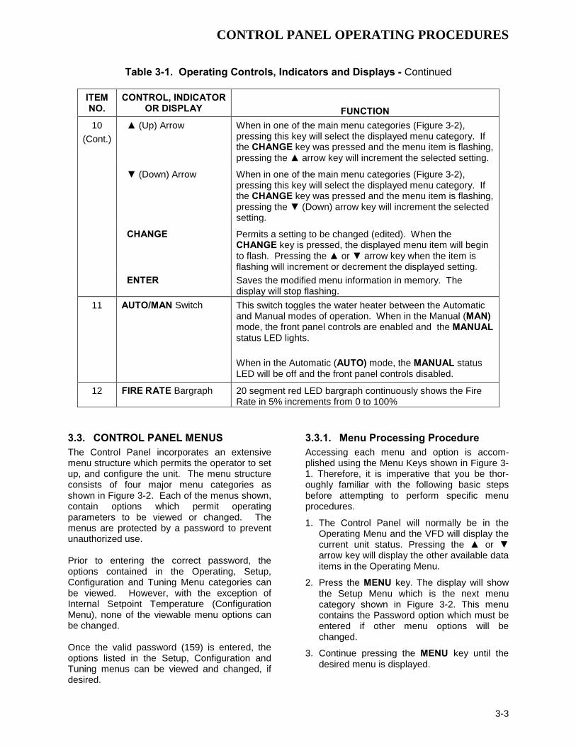
Table 3-1. Operating Controls, Indicators and Displays - Continued
ITEM NO.
CONTROL, INDICATOR OR DISPLAY
FUNCTION
10 (Cont.)
(Up) Arrow When in one of the main menu categories (Figure 3-2), pressing this key will select the displayed menu category. If the CHANGE key was pressed and the menu item is flashing, pressing the arrow key will increment the selected setting.
(Down) Arrow When in one of the main menu categories (Figure 3-2), pressing this key will select the displayed menu category. If the CHANGE key was pressed and the menu item is flashing, pressing the (Down) arrow key will increment the selected setting.
CHANGE Permits a setting to be changed (edited). When the
CHANGE key is pressed, the displayed menu item will begin to flash. Pressing the or arrow key when the item is flashing will increment or decrement the displayed setting.
ENTER Saves the modified menu information in memory. The display will stop flashing.
11 AUTO/MAN Switch This switch toggles the water heater between the Automatic and Manual modes of operation. When in the Manual (MAN) mode, the front panel controls are enabled and the MANUAL status LED lights.
When in the Automatic (AUTO) mode, the MANUAL status LED will be off and the front panel controls disabled.
12 FIRE RATE Bargraph 20 segment red LED bargraph continuously shows the Fire Rate in 5% increments from 0 to 100%
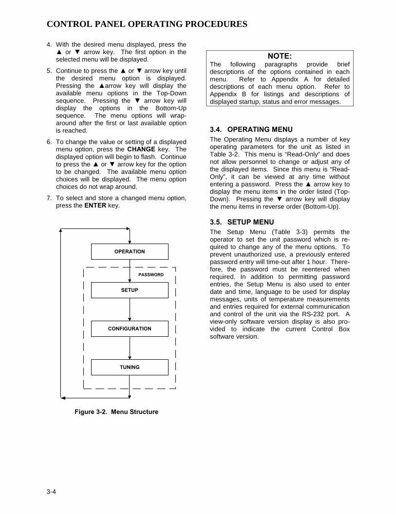
3.3. CONTROL PANEL MENUS The Control Panel incorporates an extensive menu structure which permits the operator to set up, and configure the unit. The menu structure consists of four major menu categories as shown in Figure 3-2. Each of the menus shown, contain options which permit operating parameters to be viewed or changed. The menus are protected by a password to prevent unauthorized use. Prior to entering the correct password, the options contained in the Operating, Setup, Configuration and Tuning Menu categories can be viewed. However, with the exception of Internal Setpoint Temperature (Configuration Menu), none of the viewable menu options can be changed. Once the valid password (159) is entered, the options listed in the Setup, Configuration and Tuning menus can be viewed and changed, if desired.
3.3.1. Menu Processing Procedure Accessing each menu and option is accom-plished using the Menu Keys shown in Figure 3-1. Therefore, it is imperative that you be thor-oughly familiar with the following basic steps before attempting to perform specific menu procedures.
1. The Control Panel will normally be in the Operating Menu and the VFD will display the current unit status. Pressing the or arrow key will display the other available data items in the Operating Menu.
2. Press the MENU key. The display will show the Setup Menu which is the next menu category shown in Figure 3-2. This menu contains the Password option which must be entered if other menu options will be changed.
3. Continue pressing the MENU key until the desired menu is displayed.
CONTROL PANEL OPERATING PROCEDURES
3-4
4. With the desired menu displayed, press the or arrow key. The first option in the selected menu will be displayed.
5. Continue to press the or arrow key until the desired menu option is displayed. Pressing the arrow key will display the available menu options in the Top-Down sequence. Pressing the arrow key will display the options in the Bottom-Up sequence. The menu options will wrap-around after the first or last available option is reached.
6. To change the value or setting of a displayed menu option, press the CHANGE key. The displayed option will begin to flash. Continue to press the or arrow key for the option to be changed. The available menu option choices will be displayed. The menu option choices do not wrap around.
7. To select and store a changed menu option, press the ENTER key.
OPERATION
SETUP
CONFIGURATION
TUNING
PASSWORD
Figure 3-2. Menu Structure
NOTE: The following paragraphs provide brief descriptions of the options contained in each menu. Refer to Appendix A for detailed descriptions of each menu option. Refer to Appendix B for listings and descriptions of displayed startup, status and error messages.
3.4. OPERATING MENU The Operating Menu displays a number of key operating parameters for the unit as listed in Table 3-2. This menu is “Read-Only” and does not allow personnel to change or adjust any of the displayed items. Since this menu is “Read-Only”, it can be viewed at any time without entering a password. Press the arrow key to display the menu items in the order listed (Top-Down). Pressing the arrow key will display the menu items in reverse order (Bottom-Up).
3.5. SETUP MENU The Setup Menu (Table 3-3) permits the operator to set the unit password which is re-quired to change any of the menu options. To prevent unauthorized use, a previously entered password entry will time-out after 1 hour. There-fore, the password must be reentered when required. In addition to permitting password entries, the Setup Menu is also used to enter date and time, language to be used for display messages, units of temperature measurements and entries required for external communication and control of the unit via the RS-232 port. A view-only software version display is also pro-vided to indicate the current Control Box software version.

CONTROL PANEL OPERATING PROCEDURES
3-5
NOTE The Outdoor Temp display item shown with an asterisk in Table 3-2 will not be displayed unless the Outdoor Sensor function has been enabled in the Configuration Menu (Table 3-4).
Table 3-2. Operating Menu
Available Choices or Limits Menu Item Display Minimum Maximum Default
Status Message Active Setpoint 40°F 240°F Aux Temp 30°F 245°F Outdoor Temp* -70°F 130°F Fire Rate In 0% Max Fire Rate Flame Strength 0% 100% Run Cycles 0 999,999 Run Hours 0 999,999 Fault Log 0 9 0
Table 3-3. Setup Menu
Available Choices or Limits Menu Item Display Minimum Maximum Default Passsword 0 9999 0 Language English English Time 12:00 am 11:59 pm Date 01/01/00 12/31/99 Unit of Temp Fahrenheit
Celsius Fahrenheit
Comm Address 0 127 0 Baud Rate 2400
4800 9600 19.2K
9600
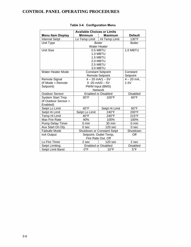
Software Ver 0.00 Ver 9.99 3.6. CONFIGURATION MENU The Configuration Menu shown in Table 3-4 permits adjustment of the Internal Setpoint (Setpt) temperature regardless of whether the valid password has been entered. Setpt is required for operation in the Constant Setpoint mode. The remaining options in this menu require the valid password to be entered, prior to changing existing entries. This menu contains a number of other configuration settings which may or may not be displayed, depending on the current operating mode setting.
NOTE: The Configuration Menu settings shown in Table 3-4 are Factory-Set in accordance with the requirements specified for each individual order. Therefore, under normal operating conditions, no changes will be required.
CONTROL PANEL OPERATING PROCEDURES
3-6
Table 3-4. Configuration Menu
Available Choices or Limits Menu Item Display Minimum Maximum Default Internal Setpt Lo Temp Limit Hi Temp Limit 130°F Unit Type Boiler
Water Heater Boiler
Unit Size 0.5 MBTU 1.0 MBTU 1.5 MBTU 2.0 MBTU 2.5 MBTU 3.0 MBTU
1.0 MBTU
Water Heater Mode Constant Setpoint Remote Setpoint
Constant Setpoint
Remote Signal (If Mode = Remote Setpoint)
4 – 20 mA/1 – 5V 0 -20 mA/0 – 5V
PWM Input (BMS) Network
4 – 20 mA, 1-5V
Outdoor Sensor Enabled or Disabled Disabled System Start Tmp (If Outdoor Sensor = Enabled)
30°F 100°F 60°F
Setpt Lo Limit 40°F Setpt Hi Limit 60°F Setpt Hi Limit Setpt Lo Limit 240°F 200°F Temp Hi Limit 40°F 240°F 215°F Max Fire Rate 40% 100% 100% Pump Delay Timer 0 min 30 min 0 min Aux Start On Dly 0 sec 120 sec 0 sec Failsafe Mode Shutdown or Constant Setpt Shutdown mA Output Setpoint, Outlet Temp,
Fire Rate Out, Off Off
Lo Fire Timer 2 sec 120 sec 2 sec Setpt Limiting Enabled or Disabled Disabled Setpt Limit Band 0°F 10°F 5°F

CONTROL PANEL OPERATING PROCEDURES
3-7
3.7. TUNING MENU The Tuning Menu items in Table 3-5 are Factory set for each individual unit.
Do not change these menu entries unless specifically requested to do so by Factory-Trained personnel.
Table 3-5. Tuning Menu
Available Choices or Limits Menu Item Display Minimum Maximum Default Min Load Adj -50°F 50°F 0°F Max Load Adj -50°F 50°F 0°F FFWD Temp 30°F 245°F Outlet Feedback On
Off On
Reset Defaults? Yes No
Are You Sure?
No
3.8. START SEQUENCE When the Control Box ON/OFF switch is set to the ON position, it checks all pre-purge safety switches to ensure they are closed. These switches include: • Safety Shut-Off Valve Proof of Closure
(POC) switch • Low Water Level switch • High Water Temperature switch • High Gas Pressure switch • Low Gas Pressure switch If all of the above switches are closed, the READY light above the ON/OFF switch will light and the unit will be in the Standby mode. When there is a demand for heat, the following events will occur:
NOTE: If any of the Pre-Purge safety device switches are open, the appropriate fault message will be displayed. Also, the appropriate fault messages will be displayed throughout the start sequence, if the required conditions are not observed.
1. The DEMAND LED status indicator will light.
2. The unit checks to ensure that the proof of closure switch in the Safety Shut-Off Valve (SSOV) is closed (Figure 3-3).
Figure 3-3.
Safety Shut-Off Valve
3. With all required safety switches closed, a purge cycle will be initiated and the following events will occur:

CONTROL PANEL OPERATING PROCEDURES
3-8
(a) Blower relay energizes and turns on blower.
(b) Air/Fuel Valve rotates to the full-open purge position and closes purge position switch. The dial on the Air/Fuel Valve (Figure 3-4) will read 100 to indicate that the valve is full-open (100%).
(c) The FIRE R ATE bargraph will show 100%.
STEPPERMOTOR
DETAIL "A"
DIAL(DETAIL “A”)
100
BLO
WE
R
BU
RN
ER
Figure 3-4.
Air/Fuel Valve In Purge Position
4. Next, the blower proof switch (Figure 3-5) closes and the display will show Purging and indicate the elapsed time of the purge cycle in seconds. The normal (default) time for the purge cycle is 7 seconds.
154 155
AIR/FUEL VALVE
BLOWER PROOFSWITCH
TO FRAMEHARNESS
Figure 3-5.
Blower Proof Switch
5. Upon completion of the purge cycle, the Control Box initiates an ignition cycle and the following events occur:
(a) The Air/Fuel Valve rotates to the low-fire ignition position and closes the ignition switch. The dial on the Air/Fuel Valve (Figure 3-6) will read between 25 and 35 to indicate that the valve is in the low-fire position.
(b) The igniter relay is activated and pro-vides ignition spark.
(c) The gas Safety Shut Off Valve (SSOV) is energized (opened) allowing gas to flow into the Air/Fuel Valve.
6. Up to 7 seconds will be allowed for ignition to be detected. The igniter relay will be turned off one second after flame is detected.
7. After 2 seconds of continuous flame, Flame Proven will be displayed and the flame strength will be indicated. After 5 seconds, the current date and time will be displayed in place of the flame strength.

CONTROL PANEL OPERATING PROCEDURES
3-9
STEPPERMOTOR
DETAIL "A"
DIAL(DETAIL “A”)
BLO
WE
R
BU
RN
ER
25
Figure 3-6.
Air/Fuel Valve In Ignition Position
8. With the unit firing properly, it will be controlled by the temperature controller cir-cuitry. The FIRE R ATE will be continuously displayed on the front panel bargraph.
9. Once the demand for heat has been satisfied, the Control Box will turn off the gas valve. The blower relay will be deactivated and the Air/Fuel Valve will be closed. Standby will be displayed.
3.9. START/STOP LEVELS The start and stop levels are the fire rate percentages that start and stop the unit, based on load. These levels are Factory preset as follows for natural gas and propane units:
• Start Level: 20% (All units) • Stop Level: 13% (Natural Gas) • Stop Level: 16% (Propane)
Normally, these settings should not require adjustment.

INITIAL START-UP
4-1
SECTION 4 - INITIAL START- UP 4.1 INITIAL START- UP REQUIREMENTS The initial start-up of the KC-1000 Water Heater is comprised of the following steps: • Installation 100% completed (Section 2) • Combustion calibration • Proper setting of controls and limits • Temperature calibration • Safety device testing (Section 5) Installation procedures must be 100% complete before performing initial start-up. The initial start-up must be successfully completed prior to plac-ing the unit into service. Starting a unit without the proper piping, venting, or electrical systems can be dangerous and void the product’s warranty. These start-up instructions should be followed precisely in order to safely operate the unit at a high thermal efficiency, and with low flue gas emissions. Initial unit start-up must be performed ONLY by AERCO factory trained start-up and service personnel. After following the steps in this section, it will be necessary to perform the safety device testing procedures in Section 5 to complete the initial unit start-up. An AERCO Gas Fired Startup Sheet included with each KC-1000 must be completed for each unit for warranty validation. A copy must be returned promptly to AERCO at: AERCO International, Inc. 159 Paris Ave. Northvale, NJ 07647
WARNING! DO NOT ATTEMPT TO FIRE THE UNIT WITHOUT FULL WATER LEVEL. THIS CAN SERIOUSLY DAMAGE THE UNIT AND MAY RESULT IN PERSONAL INJURY OR PROPERTY DAMAGE. THIS IS NOT COVERED BY WARRANTY.
CAUTION! All installation procedures in Section 2 must be completed before attempting to start the unit.
4.2 TOOLS AND INSTRUMENTATION FOR COMBUSTION CALIBRATION To properly perform combustion calibration, the proper instruments and tools must be used and correctly installed on the unit. The following paragraphs outline the necessary tools and instrumentation as well as their installation. 4.2.1 REQUIRED TOOLS AND INSTRUMENTATION The following tools and instrumentation are necessary to perform combustion calibration of the unit: 1. A digital combustion analyzer with oxygen
accuracy to 0.4%, and carbon monoxide in PPM.
2. *A 16" W.C. manometer and plastic tubing. 3. One 1/4” and two 1/8” NPT-to-barbed fittings
for use with manometers. 4. AERCO differential gas pressure regulator
adjustment tool P/N GM-122643 (one supplied per installation)
5. Small and large flat blade screwdrivers. 6. 7/16" open end wrench and small adjustable
wrenches. 7. Tube of silicone adhesive *For propane fired units, an additional 8" W.C. manometer and 1/2" NPT to barbed fitting is needed.
4.2.2 INSTALLING THE SUPPLY GAS MANOMETER 1. Close the main manual gas supply valve up
stream of the unit. 2. Remove the 1/4" NPT pipe plug from the
port on the inlet side of the safety shut off valve (see Figure 4.1).
3. Install a barbed fitting into the pipe plug
tapping. 4. Attach one end of a length of plastic tubing
to the barbed fitting and one end to the 16" W.C. manometer.

INITIAL START-UP
4-2
SSOV
1/4" NPT PLUG(INSTALLMANOMETERHERE)
Figure 4.1
1/4” Gas Plug Location
4.2.3 PREPARING THE FLUE VENT PROBE HOLE 1. If the unit has been installed using the
recommended AL29-4C vent, there will be a 3/8” hole, 18” to 24” above the exhaust manifold. The outer vent section, that covers vent section connections must be loosened and slid down to uncover the hole (see Fig. 4.2).
2. If equipped with one, adjust the stop on the
combustion analyzer probe so that it extends into the flue gas flow without hitting the opposite wall of the flue. Do not insert the probe at this time.
3/8" - 1/2"HOLE FOR
COMBUSTIONANALYZER
PROBE
EXHAUSTMANIFOLD
12" - 18"
Figure 4.2
Analyzer Probe Hole Location
4.2.4 INSTALLING THE DIFFERENTIAL REGULATOR ADJUSTMENT TOOL
1. Remove the cap from the differential pres-sure regulator (see Fig. 4.3).
2. Place the gasket from the regulator cap onto
the regulator adjustment tool. 3. Prior to Installing the tools on the regulator
pull up the tool's screwdriver blade. Then thread the tool into the regulator.
4. Engage the tool’s screwdriver blade into the
regulator’s adjustment screw slot
.
REGULATORADJUSTMENTTOOL (P/N 122643)
DIFFERENTIALPRESSUREREGULATOR
REGULATOR CAP
CAP GASKET
Figure 4.3
Differential Regulator Adjustment Tool Installation
IMPORTANT The unit is shipped from the factory set up for either natural gas or propane, as specified by the Style No. on the Sales Order. For propane units, refer to paragraph 4.4.
4.3 NATURAL GAS COMBUSTION CALIBRATION The KC-1000 is shipped combustion calibrated from the factory. Recalibration as part of a start-up is necessary due to altitude, gas BTU content, gas supply piping and supply regulators. Factory test data sheets are shipped with each unit as a reference. The following combustion calibration procedure closely follows the factory procedure. By follow-ing this procedure readjustment of combustion will be kept to a minimum.

INITIAL START-UP
4-3
1. Open the supply and return valves to the unit and ensure that the system pumps are running.
2. Open the gas supply valve(s) to the unit. 3. If a lockup style regulator is installed as a
gas supply regulator, adjust the gas supply until a reading of 12” W.C. static pressure is obtained.
4. Set the ON/OFF switch in the OFF position.
Turn on AC power to the unit. The display will show LOSS OF POWER and the time and date.
5. Set the unit to the Manual Mode by pressing
the AUTO/MAN switch. A flashing Manual Fire Rate message will be displayed with the present rate in %. Also, the MANUAL LED will light.
NOTE: For a review of control panel operating pro-cedures, see Section 3. 6. Adjust the rate to 0% by pressing the
arrow key. 7. Set the ON/OFF switch to the ON position. 8. Change the firing rate to 25% using the
arrow key. This will put the unit into the starting sequence.
NOTE:
On initial start-up, or return to service from a fault condition, the unit will remain at a 29% firing rate for two-minutes, although the control signal may indicate a greater input. 9. Following the warm-up period, increase the
firing rate in 20% increments while monitor-ing the gas pressure after every increase. If gas pressure dips below 8.5” W.C. for FM gas trains and 8.9” for IRI gas trains at any input percentage, stop and raise the pres-sure. Once 100% is reached, adjust the gas pressure for 8.5” W.C. or 8.9” W.C.
NOTE: If 8.5” W.C. for FM gas trains or 8.9” W.C. for IRI gas trains cannot be obtained at the 100% firing rate, it will be necessary to stop calibration and contact the local AERCO representative in your area. Running the unit on insufficient gas pressure will void the warranty. 10. Once 8.5” W.C. or 8.9” W.C. is set at the
100% level change the firing rate to 30%.
Insert the combustion analyzer probe into the stack.
NOTE:
Always go to a percentage of firing rate from the same direction, (i.e., 100% to 30% or 30% to 20%). Whenever going to a firing rate from below (i.e., 20% to 30%), first go above then back down to the desired firing rate. This is necessary due to hysteresis in the air/fuel stepper motor. Hysteresis causes the air/fuel valve to stop in a slightly different position if the firing rate percentage is approached from below or above. This results in a difference in oxygen readings for the same firing rate percentage causing unnecessary recalibration. 11. Allow enough time for the combustion
analyzer to settle. Compare the measured oxygen level to the oxygen range for intake air temperature in Table 1.
Table 1
Combustion Oxygen Levels for a 30% Firing Rate
Inlet Air Temp
Oxygen (+0.2/-1.0)
Carbon Monoxide
-20°F 7.5 % <50 ppm 0°F 7.3 % <50 ppm 10°F 7.2 % <50 ppm 30°F 6.8 % <50 ppm 50°F 6.4 % <50 ppm 60°F 6.2 % <50 ppm 70°F 6.0 % <50 ppm 80°F 5.8 % <50 ppm 90°F 5.6 % <50 ppm 100°F 5.4 % <50 ppm
12. If the measured oxygen level is within the
range in Table 1, no adjustment is neces-sary. Proceed to step 17.
13. If the measured oxygen level is below the
range in Table 1, rotate the differential regulator adjustment tool counterclockwise 1/4 to 1/2 revolution to decrease gas flow.
14. Wait for the combustion analyzer to settle,
then compare the new oxygen reading to Table 1. Repeat adjustment until oxygen is within the specified range.
INITIAL START-UP
4-4
15. If the measured oxygen level is above the oxygen range in Table 1, rotate the differen-tial regulator adjustment tool clockwise 1/4 to 1/2 revolution to increase gas flow.
16. Wait for the analyzer reading to settle, then
compare the new reading to Table 1. Repeat adjustment until oxygen is within the speci-fied range.
NOTE:
Adjust only the differential regulator at 30% control signal; do not adjust the air shutter. 17. Once the oxygen level is within the specified
range at 30%, change the firing rate to 16%. 18. Oxygen levels at the 16% firing rate should
be as shown in Table 2. No adjustment should be necessary. Contact the Factory if the oxygen or carbon monoxide levels are not within the specified range.
Table 2 Combustion Oxygen Levels for a 16%
Firing Rate
Inlet Air Temp
Oxygen (+0.2/-1.0)
Carbon Monoxide
-20°F <12 % <50 ppm 0°F <12 % <50 ppm 10°F <12 % <50 ppm 30°F <12 % <50 ppm 50°F <11 % <50 ppm 60°F <11 % <50 ppm 70°F <11 % <50 ppm 80°F <11 % <50 ppm 90°F <10 % <50 ppm 100°F <10 % <50 ppm
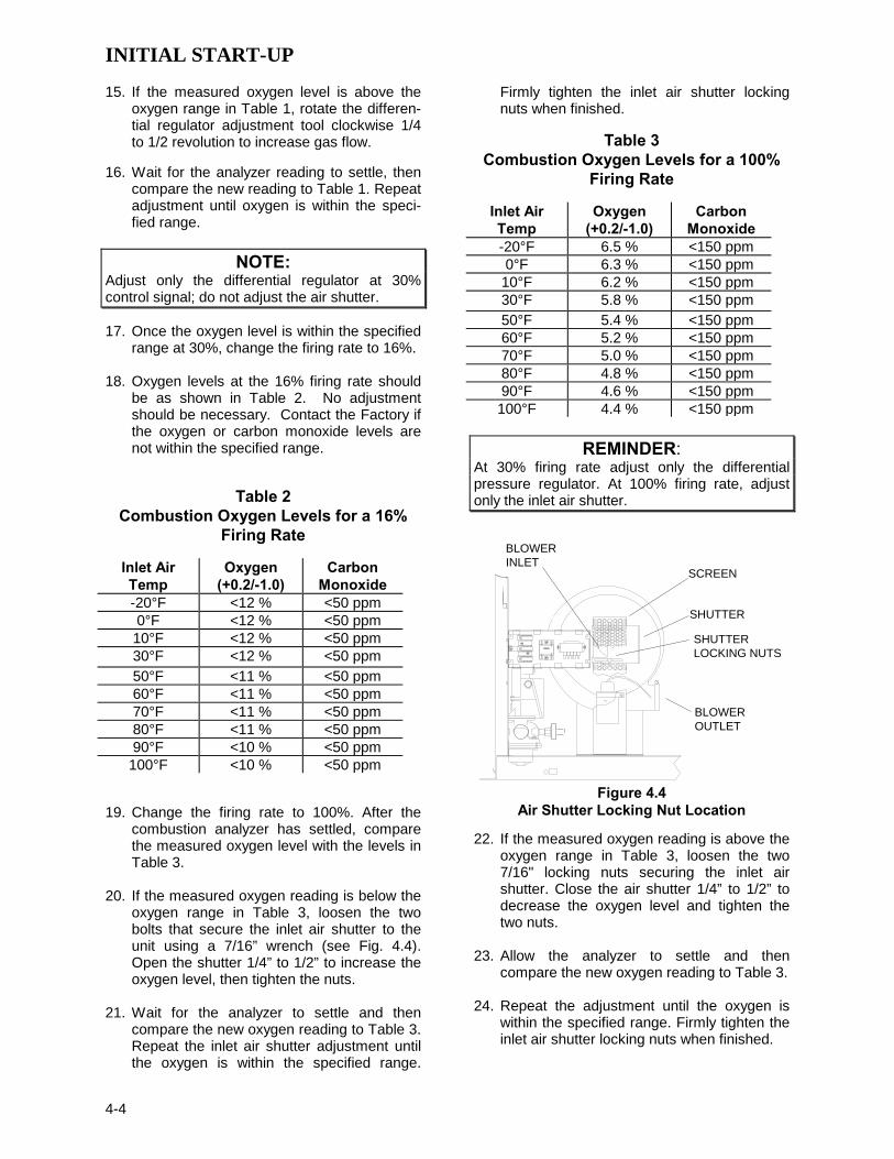
19. Change the firing rate to 100%. After the
combustion analyzer has settled, compare the measured oxygen level with the levels in Table 3.
20. If the measured oxygen reading is below the
oxygen range in Table 3, loosen the two bolts that secure the inlet air shutter to the unit using a 7/16” wrench (see Fig. 4.4). Open the shutter 1/4” to 1/2” to increase the oxygen level, then tighten the nuts.
21. Wait for the analyzer to settle and then
compare the new oxygen reading to Table 3. Repeat the inlet air shutter adjustment until the oxygen is within the specified range.
Firmly tighten the inlet air shutter locking nuts when finished.
Table 3
Combustion Oxygen Levels for a 100% Firing Rate
Inlet Air Temp
Oxygen (+0.2/-1.0)
Carbon Monoxide
-20°F 6.5 % <150 ppm 0°F 6.3 % <150 ppm 10°F 6.2 % <150 ppm 30°F 5.8 % <150 ppm 50°F 5.4 % <150 ppm 60°F 5.2 % <150 ppm 70°F 5.0 % <150 ppm 80°F 4.8 % <150 ppm 90°F 4.6 % <150 ppm 100°F 4.4 % <150 ppm
REMINDER:
At 30% firing rate adjust only the differential pressure regulator. At 100% firing rate, adjust only the inlet air shutter.
BLOWEROUTLET
BLOWERINLET
SCREEN
SHUTTER
SHUTTERLOCKING NUTS
Figure 4.4 Air Shutter Locking Nut Location
22. If the measured oxygen reading is above the oxygen range in Table 3, loosen the two 7/16" locking nuts securing the inlet air shutter. Close the air shutter 1/4” to 1/2” to decrease the oxygen level and tighten the two nuts.
23. Allow the analyzer to settle and then
compare the new oxygen reading to Table 3. 24. Repeat the adjustment until the oxygen is
within the specified range. Firmly tighten the inlet air shutter locking nuts when finished.

INITIAL START-UP
4-5
NOTE:
Adjust the inlet air shutter only at 100% firing rate. Do not adjust the differential pressure regulator. 25. Change the firing rate to 30%. Allow time for
the combustion analyzer to settle. Check the measured oxygen reading to insure that it is still within the range as per Table 1.
26. Continue this procedure until all oxygen
levels are within the ranges specified in Tables 1, 2 and 3.
27. Record all readings on the AERCO start-up
sheet provided with each unit. Proceed to paragraph 4.5.
4.4 PROPANE COMBUSTION CALIBRATION For propane units it will be necessary to install an additional 8” W.C. manometer. This manometer will be used to measure the pressure drop across the air/propane mixing orifice. After performing the setup procedures in paragraphs 4,2.2 through 4.2.4, install the 8” W.C. manometer as described in steps 1, 2 and 3 which follow. 1. Referring to Fig. 4.5, remove the 1/8” NPT
plug from the gas inlet pipe ahead of the burner and install a 1/8” NPT barbed fitting.
2. Remove the 1/2” NPT plug from the tee
located after the air pressure regulator and install a 1/2” barbed fitting (see fig. 4.5).
3. Attach the 8” W.C. manometer to the barbed
fittings installed in steps 1 and 2.
NOTE: The combustion calibration data in Tables 1, 2 and 3 apply to both natural gas and propane units. Therefore, refer to these Tables when performing propane combustion calibration.
4. While performing the combustion calibration
procedure in paragraph 4.3, measure the pressure drop across the air/propane mixing orifice using the 0-8” W.C. manometer.
5. This reading should remain a constant 3.8”
to 4” W.C. throughout the operating range.
6. If the pressure drop is not within this range, remove the cap from the air pressure regula-tor.
7. Using a flat blade screwdriver adjust the
regulator until 3.8”-4.0” W.C. is obtained. Clockwise will increase the reading and counter-clockwise will decrease the reading.
8. If adjustments are made to this regulator it
will be necessary to recheck oxygen settings at 16%, 30%, and 100% firing rates.
NOTE:
After an adjustment is made to the air regulator, the cap must be put back on securely to obtain an accurate reading.
Figure 4.5
Propane Air Differential Pressure Taps
4.5 UNIT REASSEMBLY Once combustion calibration is set properly, the unit can be re-assembled for permanent opera-tion. 1. Set the ON/OFF switch to the OFF position.
Disconnect the AC power supply from the unit.
2. Shut off the gas supply to the unit. 3. Remove any regulator adjustment tools by
first pulling up the screwdriver blade to disengage it from the regulator adjusting screw, and then turning the tool out of the top of the regulator.
4. Apply a drop of silicone to the regulator
adjusting screw to lock its setting. 5. Remove the gasket from the tool and place it
back onto the regulator cap.

INITIAL START-UP
4-6
6. Reinstall the cap and gasket back on the regulator. Tighten the cap using a screw-driver or wrench.
7. Remove all of the manometers and barbed fittings and reinstall the pipe plugs using a suitable thread compound.
8. Remove the combustion analyzer probe
from the vent hole. Seal the probe hole and replace the vent connection cover.
9. Replace the unit’s panels and hood.
4.6 TEMPERATURE CONTROL CALIBRATION Although the unit comes factory set and calibrated for a 130°
F setpoint it is usually necessary to recalibrate temperature control. There are two primary adjustments for performing temperature calibration. These are Min Load Adj and Max Load Adj (minimum and maximum load adjustment).
Adjustments to these settings are made at minimum and maximum load conditions and should be made in small increments from 1 to 3 degrees. After making an adjustment, outlet water temperature must be allowed to settle for several minutes prior to making further adjustments. When calibrating temperature control, observe the following: 1. The unit must be in the Auto mode of
operation. 2. The Outlet Feedback option in the Tuning
Menu must be off while performing calibra-tion.
3. Monitor the OUTLET T EMPERATURE dis-
play and FIRE R ATE bar-graph display to set load conditions and see the effect of adjustments.
4. Perform the calibration using the Tuning
Menu of the Control Box. 5. Make small adjustments and allow time be-
tween adjustments for the outlet temperature to stabilize.
6. Maintain water flow as constant as possible
during these adjustments. 7. Ensure that recirculation loops are opera-
tional while the calibration is being performed.
4.6.1 SETTING THE OUTLET WATER TEMPERATURE SETPOINT The setpoint temperature of the unit may be changed by following the procedure below. However, once a setpoint has been changed, recalibration may be necessary. The tempera-ture calibration procedures are provided in paragraphs 4.6.2 and 4.6.3 To adjust the unit’s setpoint, proceed as follows: 1. Press the MENU key until Configuration
Menu is displayed. 2. Press the or arrow key until Internal
Setpt is displayed along with the present setpoint temperature.
3. To change the setpoint, press the CHANGE
key. The display will begin to flash. 4. Press the or arrow key until the desired
setpoint is displayed. 5. Press the ENTER key to save the change.
4.6.2 MINIMUM LOAD ADJUSTMENT With the unit in operation, check the temperature control at minimum load as follows: 1. While monitoring the FIRE RATE display,
create a minimum load on the system that will yield a steady fire rate between 25% and 35%.
NOTE: It may be desirable to shut off the outlet valve and use the hose bib to simulate a minimum flow load condition. 2. Wait several minutes to allow the outlet
temperature to stabilize under load conditions.
3. Once stabilized, the OUTLET
TEMPERATURE display should read no more than 2 to 3 degrees above the unit’s setpoint.
4. If the outlet temperature is stabilized,
proceed to the Maximum Load Adjustment procedure in paragraph 4.6.3. If the unit is not stabilized, proceed to step 5.
5. Press the MENU key and select the Tuning
Menu.

INITIAL START-UP
4-7
6. Press the or arrow key until Min Load Adj is displayed.
7. Press the CHANGE key. The display will
begin to flash. 8. Raise or lower the minimum load adjustment
in increments of one or two using the or arrow key. Increasing this value will increase the outlet water temperature, while decreasing it will decrease the water tem-perature.
9. Press ENTER to save the change. Allow
time for the system to stabilize between adjustments
10. Repeat steps 5 through 9 as needed until
the temperature is stabilized at no more than 2 to 3 degrees above the setpoint.
4.6.3 MAXIMUM LOAD ADJUSTMENT Check the temperature control at minimum load as follows: 1. While monitoring the FIRE RATE display,
create a maximum load on the system that will yield a steady fire rate between 80% and 90%.
NOTE:
It may be necessary to open the outlet valve if it was closed during minimum load adjustment to obtain a sufficient flow rate for maximum adjustment. 2. Wait several minutes to allow the outlet
temperature to stabilize under load conditions.
3. Once the temperature has stabilized, the
OUTLET T EMPERATURE display should read no more than 2 to 3 degrees below the unit’s setpoint.
4. If the outlet temperature is stabilized, no
adjustment is necessary. If the unit is not stabilized, proceed to step 5.
5. Press the MENU key and select the Tuning
Menu. 6. Press the or arrow key until Max Load
Adj is displayed. 7. Press the CHANGE key. The display will
begin to flash.
8. Raise or lower the maximum load adjustment using the or arrow key. Increasing this value will increase outlet water temperature, while decreasing it will decrease water temperature.
9. Press ENTER to save the change. Allow
time for the system to stabilize between adjustments
10. Repeat steps 5 through 9 as needed until
the temperature is stabilized 2 to 3 degrees below the setpoint.
11. If the outlet temperature does not maintain
setpoint after a reasonable amount of time and adjustment, contact your local AERCO representative.
NOTE:
After performing Temperature Calibration and prior to placing the water heater in service, be sure to turn the Outlet Feedback option in the Tuning Menu back to ON.
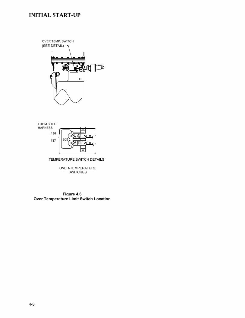
4.7 OVER-TEMPERATURE LIMIT SWITCH ADJUSTMENTS There are two Over-Temperature Limit switches that turn off the unit when the outlet water temperature becomes too hot. The lower over-temperature limit switch is adjustable and should be adjusted 20°F to 40°F above the operating header temperature. The upper over-tempera-ture limit switch is a manual reset device and is not adjustable. It will shut the unit off if the water temperature reaches 200°F. DO NOT attempt to adjust its setpoint. To adjust the lower over temperature switch limit switch: 1. Remove the wing nut from the top center of
the shell cap. Lift the cap off the shell. 2. The two over-temperature limit switches are
located at the top of the shell (see Fig. 4.6). Do not adjust the upper switch it has been factory preset. Adjust the lower switch between 20° to 40°F higher than the maximum header temperature the unit may see.
3. Replace the shell cap and wing nut.
INITIAL START-UP
4-8
OVER-TEMPERATURESWITCHES
209
TEMPERATURE SWITCH DETAILS
137
HARNESS
136
FROM SHELL
NC
NC
CNO
C
25
OVER TEMP. SWITCH
(SEE DETAIL)
Figure 4.6 Over Temperature Limit Switch Location

SAFETY DEVICE TESTING
5-1
SECTION 5 - SAFETY DEVICE TESTING PROCEDURES 5.1 TESTING OF SAFETY DEVICES Periodic testing of all controls and safety devices is required to insure that they are operating as designed. Precautions must be taken while tests are being performed to protect against bodily injury and property damage. Systematic and thorough testing of the operating and safety controls should be performed on a scheduled basis, or whenever a control compo-nent has been serviced or replaced. All testing must conform to local jurisdictions or codes such as ASME CSD-1.
NOTE: MANUAL and AUTO modes are required to perform the following tests. For a complete explanation of these modes, see Section 3.
NOTE: It will be necessary to remove the sheet metal covers and cap from the unit to perform the following tests.
WARNING! ELECTRICAL VOLTAGES IN THIS SYSTEM INCLUDE 120 AND 24 VOLTS AC. POWER MUST BE REMOVED PRIOR TO PERFORMING WIRE REMOVAL OR OTHER TESTING PROCEDURES THAT CAN RESULT IN ELECTRICAL SHOCK. 5.2 LOW GAS PRESSURE FAULT TEST 1. Shut off the gas supply to the unit. 2. Install a 0-16” W.C. manometer in the gas
pipe assembly below the low gas pressure switch. (See Fig. 5.1)
3. Open the gas supply to the unit and depress
the CLEAR button to clear any fault mes-sages..
4. Place the unit in Manual Mode and fire the
unit at a firing rate between 25% and 30%. 5. Slowly close the manual gas supply valve
while monitoring the gas pressure. The unit should fault and shutdown on LOW GAS PRESSURE when the manometer indicates approximately 6.5” W.C.
6. Open the gas supply to the unit and press the CLEAR button on the Control Box.
7. The unit should restart.
1/4" NPT PLUG(INSTALLMANOMETER
HERE)
SSOV
Figure 5.1
1/8” Pipe Plug Position for Manometer Installation
NOTE: After faulting the unit, the fault message will be displayed and the fault indicator light will flash until the CLEAR button is pressed.
5.3 HIGH GAS PRESSURE TEST 1. Start the unit in manual mode and fire be-
tween 25% and 30%. 2. Remove either wire # 150 or wire #151 from
the high gas pressure switch. See Fig. 5.2. 3. The unit should shut down on a HIGH GAS
PRESSURE FAULT. 4. Reconnect the wire previously removed from
the high gas pressure switch and depress the CLEAR button.
5. The unit should restart.

SAFETY DEVICE TESTING
5-2
HIGH GASPRESSURE
SWITCH
Figure 5.2
High Gas Pressure Switch 5.4 LOW WATER LEVEL FAULT TEST 1. Set the ON/OFF switch in the OFF position. 2. Close the shut-off valves in the supply and
return piping to the unit. 3. Open the drain valve on the unit. 4. Allow air flow into the unit by either opening
the relief valve or by removing the 1/4” plug in the top of the unit.
5. The LOW WATER LEVEL message will be
displayed and the FAULT LED will flash after the water level has gone below the level of the probe.
6. Set the ON/OFF switch to ON. The READY
light should remain off and the unit should not start. If the unit does start, shut the unit off immediately and refer fault to qualified service personnel.
7. Close the drain and pressure relief valve or
reinstall the plug in the top of the unit if removed.
8. Open the water shut-off valve in the return
piping to the unit to fill the shell. 9. Open the water shut-off valve in the supply
piping to the unit.
10. After the shell is full, press the LOW WATER LEVEL RESET button to reset the low water cutoff. Press the CLEAR button to reset the FAULT LED and clear the error message.
11. Set the ON/OFF switch to the ON position.
The unit is now ready for operation. 5.5 WATER TEMPERATURE FAULT TEST 1. In the normal operating mode, allow the unit
to stabilize at its setpoint. 2. Lower the adjustable temperature limit
switch setting to match the outlet water tem-perature. (See Fig. 5.3).
209137
HARNESS
136
FROM SHELL
NC
NC
CNO
C
120
180
150
DIAL
TEMPERATURE LIMIT SWITCHSETTING
Figure 5.3 Temperature Limit Switch Setting
3. Once the switch setting is approximately at the actual water temperature, the unit should shutdown. The FAULT LED should be flashing and the message HIGH WATER TEMP SWITCH OPEN should be displayed. The unit should not start.
4. Reset the temperature limit switch setting to
its prior setting. 5. The unit should start once the adjustable
temperature limit switch setting is above the actual outlet water temperature.

SAFETY DEVICE TESTING
5-3
5.6 INTERLOCK TESTS The unit is equipped with two interlock circuits called the Remote Interlock and Delayed Inter-lock. Terminal connections for these circuits are located in the I/O Box and are labeled REMOTE INTL’K IN and DELAYED INTL’K IN. These circuits can shut down the unit in the event that an interlock is opened. These interlocks are shipped from the factory jumped (closed). However, each of these interlocks may be utilized in the field as a remote stop and start, an emergency cut-off, or to prove that a device such as a pump gas booster, or louver is operational.
5.6.1 REMOTE INTERLOCK 1. Remove the cover from the I/O Box and
locate the REMOTE INTL’K IN terminals. 2. Start the unit in manual mode and fire at
25% to 30% firing rate. 3. If there is a jumper across the REMOTE
INTL’K IN terminals, remove one side of the jumper. If the interlock is being controlled by an external device, either open the interlock via the external device or disconnect one of the wires leading to the external device.
4. The unit should shut down and display
INTERLOCK OPEN. 5. Once the interlock connection is recon-
nected, the INTERLOCK OPEN message should automatically clear and the unit should resume running.
5.6.2 DELAYED INTERLOCK 1. Remove the cover from the I/O Box and
locate the DELAYED INTL’K IN terminals. 2. Start the unit in manual mode and fire at a
25% to 30% firing rate. 3. If there is a jumper across the DELAYED
INTL’K IN terminals, remove one side of the jumper. If the interlock is connected to a proving switch of an external device, discon-nect one of the wires leading to the proving switch.
4. The unit should shut down and display
DELAYED INTERLOCK OPEN. The FAULT LED should be flashing.
5. Once the interlock connection is recon-nected, depress the CLEAR button. The unit should start.
5.7 FLAME FAULT TEST 1. Place the ON/OFF switch in the OFF
position. 2. Place the unit in the Manual Mode and set
the firing rate between 25% and 30%. 3. Close the manual leak detection valve
located between the safety shut-off valve and the differential regulator (see Fig. 5.4).
4. Start the unit. 5. The unit should shut down after reaching the
Ignition cycle and display FLAME LOSS DURING IGN.
6. Open the valve previously closed in step 3
and depress the CLEAR button. 7. Restart the unit and allow it to prove flame. 8. Once flame is proven, close the manual leak
detection valve located between the safety shut-off valve and the differential regulator.
9. The unit should shut down and display
FLAME LOSS DURING RUN. 10. Open the valve previously closed in step 8
and depress the CLEAR button. The unit should restart and fire.
Figure 5.4
Manual Leak Detection Valve

SAFETY DEVICE TESTING
5-4
5.8 AIR FLOW FAULT TEST 1. Start the unit in manual mode and set the
fire rate between 25% and 30%. 2. Once the unit has proved flame, remove
either wire #154 or #155 from the blower proof switch (see Fig. 5.5) located on the air/fuel valve.
3. The unit should shut down and display
AIRFLOW FAULT DURING RUN. 4. Replace the wire previously removed from
the blower-proof switch and depress the CLEAR button. The unit should restart.
WARNING! ELECTRICAL VOLTAGES IN THIS SYSTEM INCLUDE 120 AND 24 VOLTS AC. POWER MUST BE REMOVED PRIOR TO PERFORMING WIRE REMOVAL OR OTHER TESTING PROCEDURES THAT CAN RESULT IN ELECTRICAL SHOCK.
154 155
AIR/FUEL VALVE
BLOWER PROOFSWITCH
TO FRAMEHARNESS
Figure 5.5 Blower Proof Switch Location and Wiring
5.9 SSOV PROOF OF CLOSURE SWITCH 1. Set the unit’s ON/OFF switch to the OFF
position. Place the unit in manual mode and set the fire rate between 25% and 30%.
2. Remove the Safety Shut-Off Valve (SSOV)
cover to access the terminal connections. See Fig. 5.6. For units with IRI gas trains, access the terminal connections of the downstream SSOV (see drawing SD-A-606 in Appendix E).
3. Remove either wire #149 or #148 from the
SSOV. 4. The unit should fault and display SSOV
SWITCH OPEN. 5. Replace the wire previously removed and
depress the CLEAR button. 6. Start the unit. 7. Remove the wire again when the unit
reaches the purge cycle. 8. The unit should shut down and display
SSOV FAULT DURING PURGE. 9. Replace the wire on the SSOV and depress
the CLEAR button. The unit should restart.
SSOVACTUATOR
COVER
SSOVCOVERSCREW
Figure 5.6
SSOV Actuator Cover Screw Location
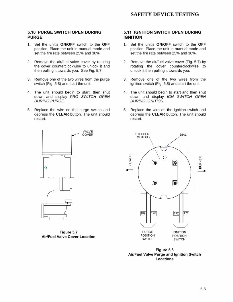
SAFETY DEVICE TESTING
5-5
5.10 PURGE SWITCH OPEN DURING PURGE 1. Set the unit’s ON/OFF switch to the OFF
position. Place the unit in manual mode and set the fire rate between 25% and 30%.
2. Remove the air/fuel valve cover by rotating
the cover counterclockwise to unlock it and then pulling it towards you. See Fig. 5.7.
3. Remove one of the two wires from the purge
switch (Fig. 5.8) and start the unit. 4. The unit should begin to start, then shut
down and display PRG SWITCH OPEN DURING PURGE.
5. Replace the wire on the purge switch and
depress the CLEAR button. The unit should restart.
VALVECOVER
Figure 5.7 Air/Fuel Valve Cover Location
5.11 IGNITION SWITCH OPEN DURING IGNITION 1. Set the unit’s ON/OFF switch to the OFF
position. Place the unit in manual mode and set the fire rate between 25% and 30%.
2. Remove the air/fuel valve cover (Fig. 5.7) by
rotating the cover counterclockwise to unlock it then pulling it towards you.
3. Remove one of the two wires from the
ignition switch (Fig. 5.8) and start the unit. 4. The unit should begin to start and then shut
down and display IGN SWITCH OPEN DURING IGNITION.
5. Replace the wire on the ignition switch and
depress the CLEAR button. The unit should restart.
IGNITIONPOSITIONSWITCH
PURGEPOSITIONSWITCH
169 170 172 171
STEPPERMOTOR
DIAL
BLO
WE
R
BU
RN
ER
Figure 5.8 Air/Fuel Valve Purge and Ignition Switch
Locations

SAFETY DEVICE TESTING
5-6
5.12 SAFETY PRESSURE RELIEF VALVE TEST Test the safety Pressure Relief Valve in accordance with ASME Boiler and Pressure Vessel Code, Section VI.

MAINTENANCE
6-1
SECTION 6 – MAINTENANCE
6.1 MAINTENANCE SCHEDULE The KC1000 Heater requires regular routine maintenance to maintain efficiency and reliability. For best operation and life of the unit, the following routine maintenance procedures should be performed in the time periods specified in Table 6-1. Appendix I contains recommended spare parts lists for maintenance of the KC1000 Heater.
WARNING! TO AVOID PERSONAL INJURY, BEFORE SERVICING:
(A) DISCONNECT AC POWER TO THE UNIT (B) SHUT OFF THE GAS SUPPLY TO THE UNIT
(C) ALLOW THE UNIT TO COOL TO A SAFE TEMPERATURE
6.2 SPARK IGNITOR The spark ignitor (part no.GP-122435-S) is located in the body of the burner (see Fig. 6.1). The ignitor may be HOT. Care should be exercised. It is easier to remove the ignitor from the unit after the unit has cooled to room temperature.
CAUTION! The ignitor must be removed and installed using the ignitor removal tool provided with the unit(s). Damage to the burner due to using a socket for removal and installation of the ignitor is not covered under warranty To inspect/replace the Ignitor: 1. Set the ON/OFF switch on the control panel to the OFF position and disconnect AC power from the
unit. 2. For access to the spark ignitor, remove the unit’s right side panel. Access can also be gained tby
removing the rear panels and condensate drainage system 3. Disconnect the ignitor cable from the ignitor extension. Remove the silicone ignitor plug from the
burner shell by simultaneously twisting and pulling downward. 4. Insert the ignitor removal tool into the burner shell, where the ignitor plug was removed. Screw the
outer barrel of the tool into the burner shell. Push the inner barrel up and fit the hexagonal end of the tool over the ignitor. Unscrew the ignitor from the burner head and then the tool from the burner shell.
5. The ignitor is gapped at 1/8-inch. If there is a substantial erosion of the spark gap or ground electrode,
the ignitor should be replaced. If carbon build-up is present, clean the ignitor using fine emery cloth. Repeated carbon build-up on the ignitor is an indication that a check of the combustion settings is required (refer to Section 4 for Combustion Calibration).
6. Prior to reinstalling the ignitor, a very light coating of anti-seize compound must
be applied to the ignitor threads.
CAUTION! The ignitor must be removed and installed using the ignitor removal tool provided with the unit(s). Damage to the burner due to using a socket for removal and installation of the ignitor is not covered under warranty. 7. Reinstall the ignitor assembly using the ignitor removal tool. Do not over tighten the ignitor. A slight
snugging up is sufficient. 8. Reinstall the ignitor plug into the burner shell by simultaneously twisting and pushing it into the shell. 9. Reattach the ignitor cable to the extension and verify that it “clicks” into place. 10. Replace the rear cover panels or right side panel. Replace the condensate cup to drain tubing.

MAINTENANCE
6-2
SPARK IGNITORASSEMBLY
BURNERSHELL
FLAMEDETECTOR
SILICONEPLUG
Figure 6.1 Spark Ignitor and Flame Detector Location
Table 6-1. Maintenance Schedule
Section Item 6 Mos. 12 Mos. 24 Mos. Labor Time 6.2 Spark Ignitor
(GP-122435-S) Inspect Replace 15 mins.
6.3 Flame Detector (GM-123428) Inspect Replace 15 mins.
6.4 Combustion Adjustments. Check Check 1 hr.
6.5 Testing of Safety Controls Test 20 mins.
6.6 BTU Transmitter Pump Oil 15 mins.
6.7 BTU Transmitter Inspect & clean if necessary 50 mins.
6.8 *Manifold & Tubes Inspect & clean if
necessary 4 hrs.
6.9 Heat Exchanger **Inspect Inspect and Clean (as required)
Inspect and Clean (as required) 1.5 to 3.5 hrs.
6.10 Condensate Drain Inspect Inspect &
Clean 30 mins.
6.11 Low Water Cutoff Probe (69126) Inspect Inspect Replace (Every 24
Mos.) 20 mins.
* Recommended only when unit will be run in an extreme condensing mode for prolonged periods of time. ** In areas where water quality is poor or not qualified, inspection and cleaning may be required to assure trouble-free operation. Hard water deposits must be removed to prevent corrosion and leaking. Checking at more frequent intervals may be required to prevent scale buildup. See page 6-13 for information about removing scale deposits using AERCO HydroSkrub scale remover.
6.3 FLAME DETECTOR The flame detector (part no. GM-123428) is located in the body of the burner (see Fig. 6.1). The flame detector may be HOT. Allow the unit to cool sufficiently before removing the flame detector. To inspect or replace the flame detector: 1. Set the ON/OFF switch on the control panel, to the OFF position and disconnect AC power from the
unit.

MAINTENANCE
6-3
2. Remove the left side panel from the unit.
3. Disconnect the flame detector lead wire and unscrew the flame detector and remove it from the burner.
4. Inspect the detector thoroughly. If eroded, the detector should be replaced. A white coating is an indication of oxidation, which may be removed with an abrasive cloth (such as Scotch Brite).
NOTE: Although flame strength may be checked using the C-More controller display (see OPERATING MENU, Section 3.4 on page 3-5 and Table 3.2), it is strongly recommended that you instead use the procedure as described in Section 6.3, page 6-18 for accurate flame strength measurement and to assure trouble free operation of the flame detection circuit.
5. Reinstall the flame detector hand tight only, and reconnect the flame detector lead wire.
6. Replace any panels previously removed.
6.4 COMBUSTION CALIBRATION Combustion settings must be checked at the intervals shown in Table 6-1 as part of the maintenance requirements. Refer to Section 4 for combustion calibration instructions.
6.5 SAFETY DEVICE TESTING Systematic and thorough tests of the operating and safety devices should be performed to ensure that they are operating as designed. Certain code requirements, such as ASME CSD-1, require that these tests be performed on a scheduled basis. Test schedules must conform to local jurisdictions. The results of the tests should be recorded and preserved as directed by ruling jurisdictions. See Section 5-Safety Device Testing Procedures.
6.6 BTU TRANSMITTER PUMP LUBRICATION The BTU Transmitter pump should be lubricated every six months. There are two oil ports located on the top of the pump, (see Fig. 6.2). Oil using 4 to 5 drops of SAE20 weight non-detergent oil at each port. DO NOT OVER OIL.
Figure 6.2
BTU Transmitter Pump Oil Port Locations
6.7 BTU TRANSMITTER ASSEMBLY The BTU Transmitter is a crucial part of the unit’s temperature control system. It must be inspected and kept free of scale and debris in order for the unit to maintain accurate outlet water temperatures. To inspect the transmitter: 1. Place the ON/OFF switch in the OFF position. 2. Remove the sheet metal side panels and hood from the unit.

MAINTENANCE
6-4
3. Shut the water inlet, outlet and recirculation valves to the unit. 4. Open the drain valve on the unit. 5. Slowly open the pressure relief valve to allow air-flow into the unit. 6. Fully drain the unit. 7. Disconnect electrical power from the unit. 8. Remove the 4 screws holding the BTU transmitter pump to the impeller housing. Remove and set the
pump aside, (See Fig. 6.3).
NOTE: It is not necessary to disconnect the electrical wires to the pump.
Figure 6.3
BTU Transmitter Pump Disassembly
9. Using a 5/8” and 9/16” wrench, loosen the 4 compression fittings holding the lower tubing assembly in place, (See Fig. 6.4).
COMPRESSIONFITTINGS
LOWER TUBING ASSEMBLY

MAINTENANCE
6-5
Figure 6.4 Compression Fitting Locations
10. Carefully remove the lower tubing assembly taking care not to lose either the cold water or hot water
mixing orifice, (See Fig. 6.5). 11. Loosen the compression fitting holding the hydraulic zero and control orifice tube assembly to the
pump’s impeller housing, (See Fig. 6.6).
NOTE: The cold water mixing orifice (P/N GP-122401) is slightly larger than the hot water mixing orifice (P/N GP-
122760). Each orifice must be correctly installed for proper temperature control.
HYDRAULIC ZERO & CONTROL ORIFICE TUBING ASSEMBLY
COLD WATER MIXING ORIFICE
HOT WATER MIXING ORIFICE
HYDRAULIC ZERO NEEDLE VALVE
LOWER TUBING ASSEMBLY
Figure 6.5 BTU Transmitter Disassembly
COMPRESSIONFITTINGS
IMPELLERHOUSING
PUMP OUTLETTUBE

MAINTENANCE
6-6
Figure 6.6 BTU Transmitter Pump Compression Fitting Locations
12. Remove the compression fitting at the top of the impeller housing and remove the impeller housing,
(See Fig. 6.6). HOT WATER TUBE
COMPRESSION FITTING
BALL VALVE
Figure 6.7 BTU Transmitter Hot Water Tube Disassembly
13. Remove the compression fitting securing the pump outlet tube to the ball valve and remove the pump outlet tube.
14. Remove the ball valve connected to the hot water tube coming from the top of the shell by loosening
the compression fitting securing it to the hot water tube, (See Fig. 6.7).
15. Loosen the compression fitting at the top of the shell holding the hot water tube, (See Fig. 6.8). Slide the hot water tube down slightly but do not remove it from the unit. Remove the
16. Inspect all fittings and tubing for blockage due to scale or debris. Clean or replace as necessary.
fitting.
17. Inspect the mixing orifice for blockage or degradation due to erosion, (See Fig. 6.5). Clean or replace as necessary.
18. The pump impeller may be checked by removing the 4 screws from the cover encasing the impeller in the housing, (See Fig. 6.9).
HOT WATER TUBE
COMPRESSION FITTING

MAINTENANCE
6-7
Figure 6.8 BTU Transmitter Shell Components
IMPELLER HOUSING
COVER
Figure 6.9 Impeller Housing Disassembly
19. Once the BTU transmitter has been inspected and cleaned, reassemble in the reverse order.
NOTE:
Do not attempt to adjust the Hydraulic Zero Needle Valve. This is a factory-preset item. Refer to Figure 6.5. If setting has been tampered with or BTU transmitter is being replaced, see procedure in Section
6.12, page 6-17.
NOTE: Compression fittings are nickel-plated and should be replaced only with nickel-plated fittings. Do not use
brass fittings.
6.8 MANIFOLD AND EXHAUST TUBES The presence of even trace amounts of chlorides and/or sulfur, in the combustion air and fuel sources, can lead to the formation of deposits on the inside of the exchanger tubes, the exhaust manifold, and/or the condensate cup. The degree of deposition is influenced by the extent of the condensing operation and the chloride and sulfur levels that vary significantly from application to application. The following parts will be necessary for reassembly after inspection:
GP-122537 Exhaust Manifold to Combustion Chamber
Gasket GP-18900 Manifold to Tubesheet
Gasket GP-18899 Burner Gasket GP-122551 Burner Release Gasket GP-161151 Combustion Chamber Liner
To remove the manifold for inspection: 1. Disconnect AC power and turn off the gas supply to the unit. 2. Remove the sheet metal covers from the unit. 3. Disconnect the plastic tubing from the condensate cup to drain and remove the rear covers.
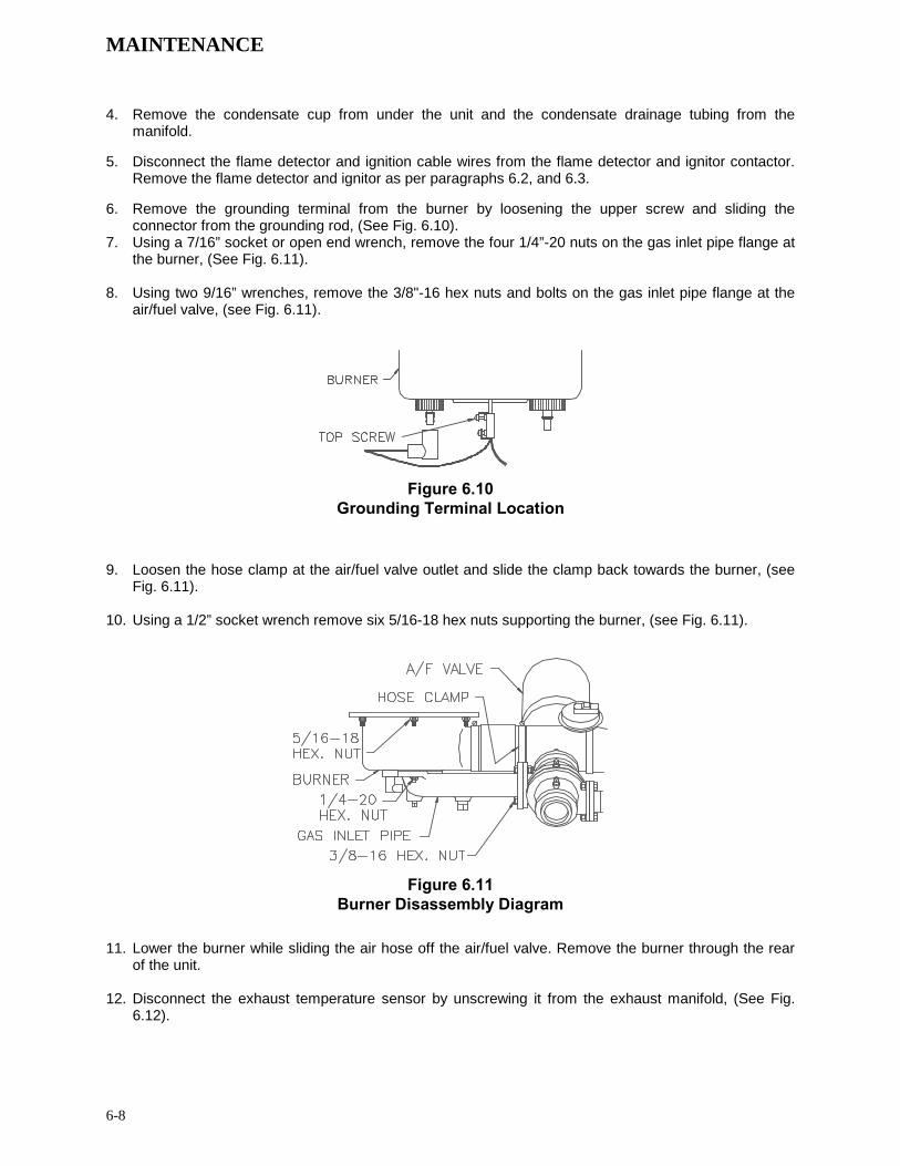
MAINTENANCE
6-8
4. Remove the condensate cup from under the unit and the condensate drainage tubing from the manifold.
5. Disconnect the flame detector and ignition cable wires from the flame detector and ignitor contactor.
Remove the flame detector and ignitor as per paragraphs 6.2, and 6.3. 6. Remove the grounding terminal from the burner by loosening the upper screw and sliding the
connector from the grounding rod, (See Fig. 6.10). 7. Using a 7/16” socket or open end wrench, remove the four 1/4”-20 nuts on the gas inlet pipe flange at
the burner, (See Fig. 6.11). 8. Using two 9/16” wrenches, remove the 3/8"-16 hex nuts and bolts on the gas inlet pipe flange at the
air/fuel valve, (see Fig. 6.11).
Figure 6.10 Grounding Terminal Location
9. Loosen the hose clamp at the air/fuel valve outlet and slide the clamp back towards the burner, (see
Fig. 6.11). 10. Using a 1/2” socket wrench remove six 5/16-18 hex nuts supporting the burner, (see Fig. 6.11).
Figure 6.11 Burner Disassembly Diagram
11. Lower the burner while sliding the air hose off the air/fuel valve. Remove the burner through the rear
of the unit. 12. Disconnect the exhaust temperature sensor by unscrewing it from the exhaust manifold, (See Fig.
6.12).

MAINTENANCE
6-9
Figure 6.12 Exhaust Sensor Connector Location
13. Disconnect the air/fuel valve wiring harness connector from the control panel. 14. Disconnect wires #24 and #17 from the blower proof switch (See Fig. 6.13).
TO FRAMEHARNESS
BLOWER PROOF SWITCH
AIR/FUEL VALVE
Figure 6.13
Blower Proof Switch Wire Location (older style switch shown at left, newer style at right)
15. Loosen the hose clamp on the air/fuel valve inlet and slide the clamp back towards the blower, (See
Fig. 6.14).
To Frame Harness

MAINTENANCE
6-10
Figure 6.14 Air/Fuel Valve Inlet Hose Clamp
16. Using an 11/16” wrench, loosen the compression fittings on the feedback tube between the air/fuel valve and the differential pressure regulator. Remove the feedback tube, (See Fig. 6.15).
17. Using two 9/16” wrenches remove the two 3/8-16 hex nuts and bolts securing the air/fuel valve to the
differential pressure regulator, (See Fig. 6.15). 18. Remove the air/fuel valve, taking care not to damage the flexible tubing on the throat of the air/fuel
valve.
Figure 6.15 Feedback Tube and Air/Fuel Valve to Differential Regulator Bolts
19. Remove the flue venting from the exhaust manifold. 20. Removing the exhaust manifold insulation will prevent it from being damaged and will make it easier
to handle the exhaust manifold once it is removed. Using a 7/16” wrench or socket, remove the 3 bolts and fender washers securing the insulation to the exhaust manifold.
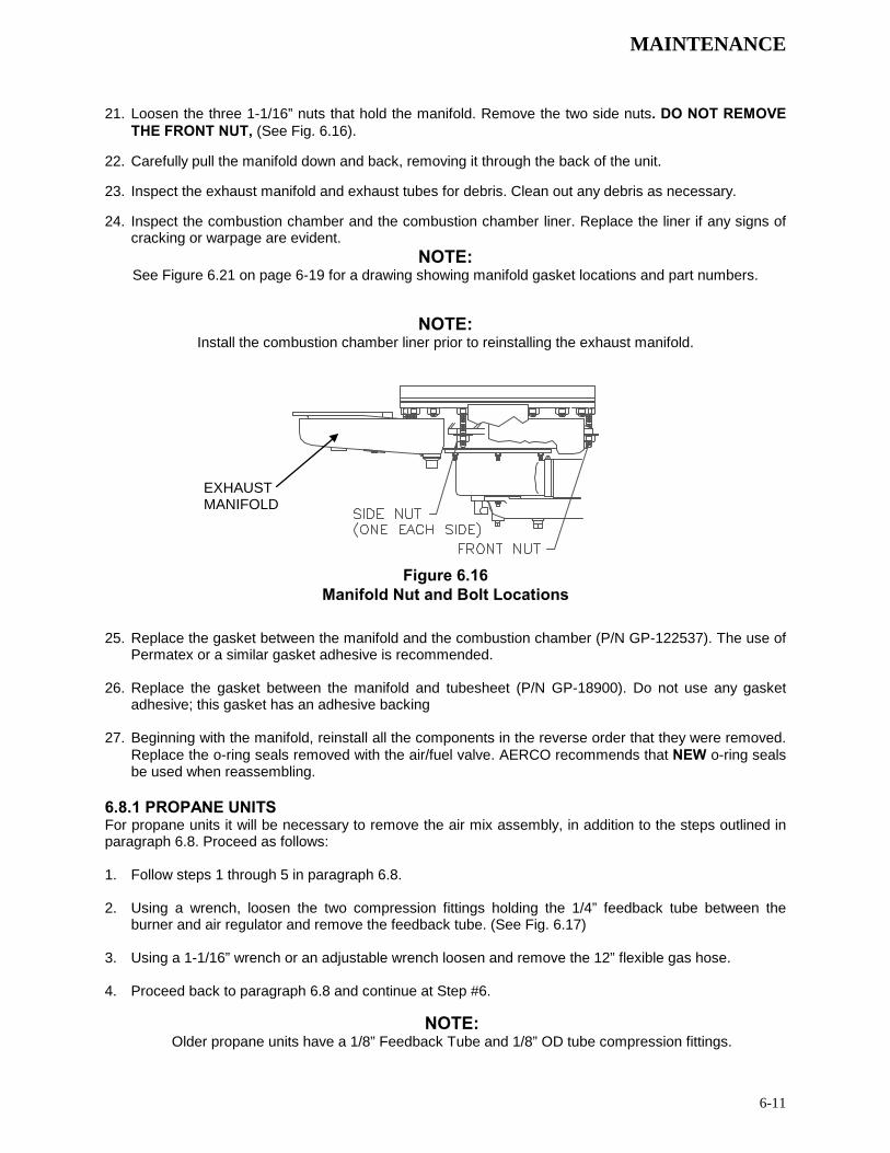
MAINTENANCE
6-11
21. Loosen the three 1-1/16” nuts that hold the manifold. Remove the two side nuts. DO NOT REMOVE THE FRONT NUT, (See Fig. 6.16).
22. Carefully pull the manifold down and back, removing it through the back of the unit. 23. Inspect the exhaust manifold and exhaust tubes for debris. Clean out any debris as necessary. 24. Inspect the combustion chamber and the combustion chamber liner. Replace the liner if any signs of
cracking or warpage are evident. NOTE:
See Figure 6.21 on page 6-19 for a drawing showing manifold gasket locations and part numbers.
NOTE:
Install the combustion chamber liner prior to reinstalling the exhaust manifold.
Figure 6.16 Manifold Nut and Bolt Locations
25. Replace the gasket between the manifold and the combustion chamber (P/N GP-122537). The use of
Permatex or a similar gasket adhesive is recommended. 26. Replace the gasket between the manifold and tubesheet (P/N GP-18900). Do not use any gasket
adhesive; this gasket has an adhesive backing 27. Beginning with the manifold, reinstall all the components in the reverse order that they were removed.
Replace the o-ring seals removed with the air/fuel valve. AERCO recommends that NEW o-ring seals be used when reassembling.
6.8.1 PROPANE UNITS For propane units it will be necessary to remove the air mix assembly, in addition to the steps outlined in paragraph 6.8. Proceed as follows: 1. Follow steps 1 through 5 in paragraph 6.8. 2. Using a wrench, loosen the two compression fittings holding the 1/4” feedback tube between the
burner and air regulator and remove the feedback tube. (See Fig. 6.17) 3. Using a 1-1/16” wrench or an adjustable wrench loosen and remove the 12” flexible gas hose. 4. Proceed back to paragraph 6.8 and continue at Step #6.
NOTE: Older propane units have a 1/8” Feedback Tube and 1/8” OD tube compression fittings.
EXHAUST MANIFOLD
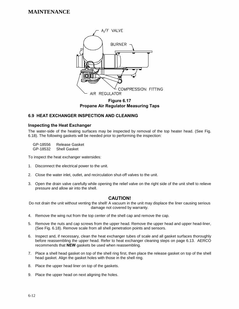
MAINTENANCE
6-12
Figure 6.17 Propane Air Regulator Measuring Taps
6.9 HEAT EXCHANGER INSPECTION AND CLEANING Inspecting the Heat Exchanger The water-side of the heating surfaces may be inspected by removal of the top heater head. (See Fig. 6.18). The following gaskets will be needed prior to performing the inspection:
GP-18556 Release Gasket GP-18532 Shell Gasket
To inspect the heat exchanger watersides: 1. Disconnect the electrical power to the unit. 2. Close the water inlet, outlet, and recirculation shut-off valves to the unit. 3. Open the drain valve carefully while opening the relief valve on the right side of the unit shell to relieve
pressure and allow air into the shell.
CAUTION! Do not drain the unit without venting the shell! A vacuum in the unit may displace the liner causing serious
damage not covered by warranty. 4. Remove the wing nut from the top center of the shell cap and remove the cap. 5. Remove the nuts and cap screws from the upper head. Remove the upper head and upper head-liner,
(See Fig. 6.18). Remove scale from all shell penetration points and sensors. 6. Inspect and, if necessary, clean the heat exchanger tubes of scale and all gasket surfaces thoroughly
before reassembling the upper head. Refer to heat exchanger cleaning steps on page 6.13. AERCO recommends that NEW gaskets be used when reassembling.
7. Place a shell head gasket on top of the shell ring first, then place the release gasket on top of the shell
head gasket. Align the gasket holes with those in the shell ring. 8. Place the upper head liner on top of the gaskets. 9. Place the upper head on next aligning the holes.
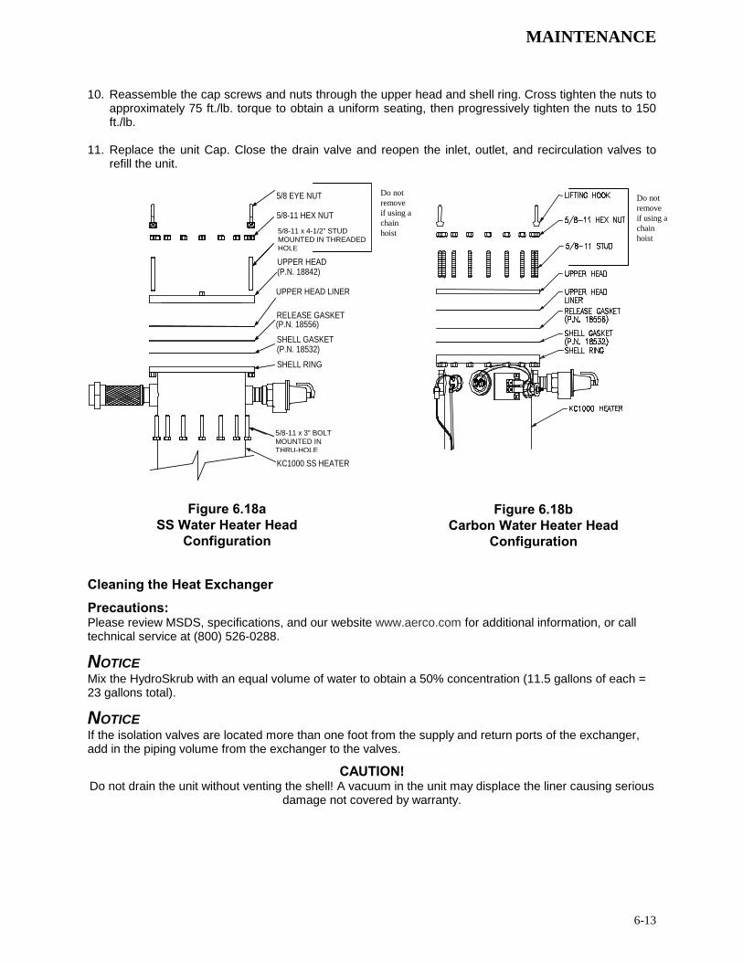
MAINTENANCE
6-13
10. Reassemble the cap screws and nuts through the upper head and shell ring. Cross tighten the nuts to approximately 75 ft./lb. torque to obtain a uniform seating, then progressively tighten the nuts to 150 ft./lb.
11. Replace the unit Cap. Close the drain valve and reopen the inlet, outlet, and recirculation valves to
refill the unit.
5/8-11 HEX NUT
5/8-11 X 3" CAP SCREW
KC1000 SS HEATER
5/8 EYE NUT
5/8-11 X 4-1/2" STUD
UPPER HEAD (P.N. 18842)
UPPER HEAD LINER
RELEASE GASKET(P.N. 18556)SHELL GASKET(P.N. 18532)SHELL RING
Cleaning the Heat Exchanger
Precautions: Please review MSDS, specifications, and our website www.aerco.com for additional information, or call technical service at (800) 526-0288.
NOTICE Mix the HydroSkrub with an equal volume of water to obtain a 50% concentration (11.5 gallons of each = 23 gallons total).
NOTICE If the isolation valves are located more than one foot from the supply and return ports of the exchanger, add in the piping volume from the exchanger to the valves.
CAUTION! Do not drain the unit without venting the shell! A vacuum in the unit may displace the liner causing serious
damage not covered by warranty.
Figure 6.18b Carbon Water Heater Head
Configuration
Figure 6.18a SS Water Heater Head
Configuration
5/8-11 x 4-1/2” STUD MOUNTED IN THREADED HOLE
Do not remove if using a chain hoist
Do not remove if using a chain hoist
5/8-11 x 3” BOLT MOUNTED IN THRU-HOLE

MAINTENANCE
6-14
Figure 6.19 – HydroSkrub Pumping System Set-Up Diagram for KC-1000 Pumping System Set-Up Directions 1. Turn off the water heater and close all isolation valves.
2. Drain at least half of the Heat Exchanger water-side volume. The KC-1000 heat exchanger holds a total volume of 23 gallons. Use 11.5 gallons of HydroSkrub mixed with an equal volume of water (23 gallons of HydroSkrub/water solution) to clean.
3. Close the Drain Valve.
4. Check that all connections are secure and all appropriate equipment valves are open.
Cleaning Procedure 5. Slowly add prescribed amount of HydroSkrub to the circulating bucket.
6. If recommended quantity exceeds volume of the bucket, turn on pump at this stage.
7. Plug in the pump and periodically check for leaks. Maintain liquid level in the bucket, as a lowering volume indicates an open drain or system. Operating level should be 1/3 of the receiving bucket, the remaining space is for foaming and expansion.
8. Check circuit again. The HydroSkrub solution should flow from the circulation bucket, through the pump and the equipment and back to the top of the bucket.
9. Return discharge foaming indicates active HydroSkrub solution and presence of mineral deposits.
10. Additional HydroSkrub and/or water may be required to maintain circulation and to prevent the pump from cavitating.
11. Circulate through the Heat Exchanger and piping for 1 to 3 hours. Estimate circulation period based on the time in service and water hardness. If heating equipment is more than 40 gallons, circulation time may need to be extended to complete cleaning. When foaming action stops, HydroSkrub

MAINTENANCE
6-15
strength is depleted (two pounds of deposits removed per gallon used) or the equipment is free from calcium and other water formed mineral deposits.
12. Periodically test the solution for effectiveness to determine if more HydroSkrub is needed—refer to “Testing hydroSkrob Effectiveness” for details. If the cleaning solution is expended before circulation time is up, additional HydroSkrub will be needed and circulation time may be extended to complete the cleaning.
13. Upon completion, begin flushing procedure by adding water to the circulation bucket, then disconnect return valve from the circulating bucket and thoroughly flush. Continue water flushing the equipment for a minimum of 10 minutes or until discharge runs clear.
14. HydroSkrub is biodegradable, and in most instances may be purged down sewers. Check with local authorities before disposing of any complex compositions.
15. Turn off water, unplug pump and immediately close discharge valves to prevent backflow.
16. Completely drain pump bucket. Disconnect hoses from equipment and liberally rinse bucket, pump, and associated hosing before neatly stowing.
Testing HydroSkrub Effectiveness There are two methods of testing the effectiveness of HydroSkrub during cleaning: the calcium carbonate spot test of the circulating solution and the charting of a trend in the pH of the cleaning solution.
Calcium Carbonate Spot Test A calcium carbonate spot test is performed by exposing a form of calcium carbonate to the HydroSkrub solution. Samples of the deposit, a Tums or Rolaids tablet, or bare concrete can be used. Observe the reaction of the HydroSkrub solution on the calcium carbonate. Foaming and bubbling indicates the solution is still active. Little or no reaction indicates that the solution is expended. This test should be performed near the end of the circulating time. If the solution has been expended, more HydroSkrub will be required to complete the job. If the solution is still active at the end of the time, all the scale has been dissolved.
pH Trend Charting The initial pH of the cleaning solution will measure between 1-3 (See pH sheet on HydroSkrub packaging). To test the effectiveness of the circulating solution as a function of pH, take readings at regular intervals and chart as a trend. Note that the deposits can cause a premature jump in the pH. After circulating for approximately 75% of the cycle time, begin testing the pH at 10-15 minute intervals. Once the solution’s pH reads 6.0-7.0 on three or more consecutive readings, the solution is expended. If the pH reads below 6.0 after the circulating time, the application is clean.
6.10 CONDENSATE DRAIN ASSEMBLY KC Heaters contain a condensate drain cup (Figure 2.5) which should be inspected and cleaned annually to ensure proper operation.
To inspect and clean, proceed as follows:
1. Remove the left side panel and left rear cover to provide access to the condensate drain components (see Figure 2.6).
2. Disconnect the drain hose attached to the exhaust manifold.
3. Disconnect the plastic tubing from the condensate cup drain tube to the drain
4. Remove the condensate cup from under the unit. Thoroughly clean the cup and inspect drain tube for blockage.
5. Check to ensure that the condensate drain opening in the exhaust manifold is not blocked.
6. Flush out the drain hose and plastic tubing.
7. After the above items have been cleaned and inspected, reassemble the condensate drain components by reversing the previous steps.
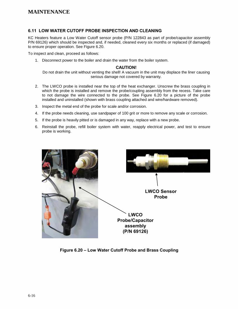
MAINTENANCE
6-16
6.11 LOW WATER CUTOFF PROBE INSPECTION AND CLEANING KC Heaters feature a Low Water Cutoff sensor probe (P/N 122843 as part of probe/capacitor assembly P/N 69126) which should be inspected and, if needed, cleaned every six months or replaced (if damaged) to ensure proper operation. See Figure 6.20.
To inspect and clean, proceed as follows:
1. Disconnect power to the boiler and drain the water from the boiler system.
CAUTION! Do not drain the unit without venting the shell! A vacuum in the unit may displace the liner causing
serious damage not covered by warranty.
2. The LWCO probe is installed near the top of the heat exchanger. Unscrew the brass coupling in which the probe is installed and remove the probe/coupling assembly from the recess. Take care to not damage the wire connected to the probe. See Figure 6.20 for a picture of the probe installed and uninstalled (shown with brass coupling attached and wire/hardware removed).
3. Inspect the metal end of the probe for scale and/or corrosion.
4. If the probe needs cleaning, use sandpaper of 100 grit or more to remove any scale or corrosion.
5. If the probe is heavily pitted or is damaged in any way, replace with a new probe.
6. Reinstall the probe, refill boiler system with water, reapply electrical power, and test to ensure probe is working.
Figure 6.20 – Low Water Cutoff Probe and Brass Coupling
LWCO Sensor Probe
LWCO Probe/Capacitor
assembly (P/N 69126)

MAINTENANCE
6-17
6.12 HYDRAULIC ZERO NEEDLE VALVE ADJUSTMENT (C-MORE CONTROL BOX) The Hydraulic Zero Needle Valve is factory set in new equipment and should not be changed unless the BTU Transmitter is being replaced. If adjustment is necessary, the following procedure must be followed to assure optimum temperature control. Hydraulic Zero Needle Valve Adjustment Instructions
1) Enter SETUP menu and change the password from 0 to 159, then press the ENTER key to activate Level 1 access.
2) Scroll through the TUNING menu until Outlet Feedback/YES is displayed. Press the CHANGE key, then using the UP or DOWN arrow keys, toggle the Outlet Feedback to NO and press ENTER to accept the change.
3) Using a 7/16” wrench, loosen the locking nut on the hydraulic zero needle valve.
4) Rotate the needle valve fully clockwise, opening the valve.
5) Start the 3 to 6 GPM flow rate through the unit.
6) Place the temperature controller in MANUAL mode and set a 20% firing rate.
7) Maintain an outlet temperature between 135° and 140° F. Adjust firing rate as necessary to maintain the above outlet temperature.
8) Scroll through the TUNING menu to get FFW Temp (Feed Forward Temperature) displayed on the top line. The temperature value is displayed on the bottom line. This is a measurement of the water temperature at the BTU transmitter sensor.
9) Adjust the needle valve until the FFW Temp is 18° to 24° F below the outlet temperature and stable (i.e., if the outlet temperature is 135° F, then the FFW Temp should read between 117° to 111° F.
Now complete the Temperature Control Calibration per Section 4.6 in this manual. At the end of that procedure, the Feedback will be turned on prior to heater operation in automatic control.
NOTES:
1) The BTU Transmitter assembly must be thoroughly cleaned prior to adjusting the Hydraulic Zero Needle Valve.
2) The lock nut on the needle valve must be loosened prior to adjustment. The needle valve must be open approximately 2-1/2 CCW turns prior to starting this procedure.
3) It is recommended that the unit’s outlet be closed off and the hose bib be used to set the 3 to 6 GPM flow rate.
4) It is mandatory that the 3 to 6 GPM be steady. VARYING flow rates will result in improper setting of the Hydraulic Zero Needle Valve and temperature control inconsistencies.
NOTE
Close the needle valve CW to lower the Feed Forward Temperature and open the needle valve CCW to raise the Feed Forward Temperature.
Once the hydraulic zero needle valve has been set, gently lock it in place using the locking nut.
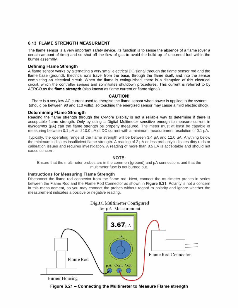
6.13 FLAME STRENGTH MEASURMENT The flame sensor is a very important safety device. Its function is to sense the absence of a flame (over a certain amount of time) and so shut off the flow of gas to avoid the build up of unburned fuel within the burner assembly.
Defining Flame Strength A flame sensor works by alternating a very small electrical DC signal through the flame sensor rod and the flame base (ground). Electrical ions travel from the base, through the flame itself, and into the sensor completing an electrical circuit. When the flame is extinguished, there is a disruption of this electrical circuit, which the controller senses and so initiates shutdown procedures. This current is referred to by AERCO as the flame strength (also known as flame current or flame signal).
CAUTION! There is a very low AC current used to energise the flame sensor when power is applied to the system
(should be between 90 and 110 volts), so touching the energized sensor may cause a mild electric shock. Determining Flame Strength Reading the flame strength through the C-More Display is not a reliable way to determine if there is acceptable flame strength. Only by using a Digital Multimeter sensitive enough to measure current in microamps (µA) can the flame strength be properly measured. The meter must at least be capable of measuring between 0.1 µA and 10.0 µA of DC current with a minimum measurement resolution of 0.1 µA.
Typically, the operating range of the flame strength will be between 3.4 µA and 12.0 µA. Anything below the minimum indicates insufficient flame strength. A reading of 2 µA or less probably indicates dirty rods or calibration issues and requires investigation. A reading of more than 8.5 µA is acceptable and should not cause concern.
NOTE: Ensure that the multimeter probes are in the common (ground) and µA connections and that the
multimeter fuse is not burned out.
Instructions for Measuring Flame Strength Disconnect the flame rod connector from the flame rod. Next, connect the multimeter probes in series between the Flame Rod and the Flame Rod Connector as shown in Figure 6.21. Polarity is not a concern in this measurement, so you may connect the probes without regard to polarity and ignore whether the measurement indicates a positive or negative reading.
Figure 6.21 – Connecting the Multimeter to Measure Flame strength

MAINTENANCE
6-19
Check for the following during the reading:
• Measure the voltage in µA between the flame rod and the flame connector. If the flame senser is operating correctly, the reading will be between 3.4 µA and 12.0 µA. If there is a lower voltage reading or no voltage, check to make sure that the wires from the control module to the flame-sensing rod are correctly connected and ensure the the flame rod or the wire connected to it is grounded properly.
• If the reading is still too low, ensure that the flame rod and burner are clean and free of dust, dirt, or debris. If they are not, take them out, clean them, and reinstall. Cleaning removes impedance from the current circuit and thus should increase the flame current.
• If a low reading is still observed, replace the flame-sensing rod. A new flame sensing rod should now produce the correct measurement. However, if an acceptable measurement is still not observed, the problem may lie in the controller.
• Chassis grounds on the shell and on the back of the C-More controller should be checked for continuity. Resistance must not exceed 1 Ω (ohm) on any ground attached to the heat exchanger and the C-More controller.
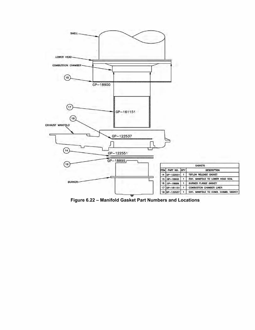
Figure 6.22 – Manifold Gasket Part Numbers and Locations
TROUBLESHOOTING
7-1
SECTION 7- TROUBLESHOOTING GUIDE
7.1 INTRODUCTION This troubleshooting guide is intended to aid service/maintenance personnel in isolating the cause of a fault in a KC 1000 Water Heater. The troubleshooting procedures contained herein are presented in tabular form on the following pages. These tables are comprised of three columns labeled: Fault Indication, Probable Cause and Corrective Action. The numbered items in the Probable Cause and Corrective Action columns correspond to each other. For example, Probable Cause No. 1 corresponds to Corrective Action No. 1, etc. When a fault occurs in the KC1000 Water Heater, proceed as follows to isolate and correct the fault: 1. Observe the fault messages displayed in the
Control Box display.
2. Refer to the Fault Indication column in the following troubleshooting tables and locate the Fault that best describes the existing conditions.
3. Proceed to the Probable Cause column and
start with the first item (1) listed for the Fault Indication.
4. Perform the checks and procedures listed in
the Corrective Action column for the first Probable Cause candidate.
5. Continue checking each additional Probable
Cause for the existing fault until the fault is corrected.
6. If the fault cannot be corrected using the
information provided in the Troubleshooting Tables, contact your local AERCO Representative.

TROUBLESHOOTING
7-2
KC1000 WATER HEATER TROUBLESHOOTING TABLE
FAULT INDICATION PROBABLE CAUSES CORRECTIVE ACTION AIRFLOW FAULT
DURING IGNITION 1. Blower stopped running due to
thermal or current overload 2. Blocked Blower inlet or inlet ductwork
3. Blocked airflow switch
4. Defective airflow switch
1. Check combustion blower for signs of excessive heat or high current drain that may trip thermal or current overload devices.
2. Inspect the inlet to the combustion blower including any duct work leading up to the combustion blower for signs of blockage.
3. Remove the airflow switch and inspect for signs of blockage, clean or replace as necessary.
4. Measure the airflow switch for continuity with the combustion blower running. If there is an erratic resistance reading or the resistance reading is greater than zero ohms, replace switch.
AIRFLOW FAULT DURING PURGE
1. Blower not running
2. Defective Air Flow Switch
3. Blocked Air flow Switch
4. Blocked Blower inlet or inlet ductwork.
5. No voltage to switch from control box.
1. Start the unit. If the blower does not run check the blower solid state relay for input and output voltage. If the relay is okay, check the blower.
2. Start the unit. If the blower runs, check the airflow switch for continuity. Replace the switch if there is no continuity.
3. Remove the air flow switch and inspect for signs of blockage, clean or replace as necessary.
4. Inspect the inlet to the combustion blower including any ductwork leading up to the combustion blower for signs of blockage.
5. Measure for 24 VAC during start sequence from each side of the switch to ground. If 24VAC is not present refer to qualified service personnel.
AIRFLOW FAULT DURING RUN
1. Blower stopped running due to thermal or current overload
2. Blocked Blower inlet or inlet ductwork
3. Blocked airflow switch
4. Defective airflow switch
5. Combustion oscillations
1. Check combustion blower for signs of excessive heat or high current draw that may trip thermal or current overload devices.
2. Inspect the inlet to the combustion blower including any ductwork leading up to the combustion blower for signs of blockage.
3. Remove the airflow switch and inspect for signs of blockage, clean or replace as necessary.
4. Measure the airflow switch for continuity with the combustion blower running. If there is an erratic resistance reading or the resistance reading is greater than zero ohms, replace the switch.
5. Run unit to full fire. If the unit rumbles or runs rough, perform combustion calibration.

TROUBLESHOOTING
7-3
KC1000 WATER HEATER TROUBLESHOOTING TABLE – Continued
FAULT INDICATION PROBABLE CAUSES CORRECTIVE ACTION DELAYED
INTERLOCK OPEN 1. Delayed Interlock Jumper not
installed or removed. 2. Device proving switch hooked to
interlocks is not closed
1. Check for a jumper properly installed across the delayed interlock terminals in the I/O box.
2. If there are 2 external wires on these terminals, check to see if an end switch for a device such as a pump, louver, etc. is tied these interlocks. Ensure that the device and or its end switch are functional. (jumper may be temporarily installed to test interlock)
DIRECT DRIVE SIGNAL FAULT
1. Unit “Type” is improperly set up as Boiler instead of Water Heater.
1. Check the “Unit Type” menu option in the Configuration Menu to ensure that the Unit Type is set to Water Heater. Change menu option if necessary.
FLAME LOSS DURING IGN
1. Worn flame detector
2. No spark from Spark Plug
3. Defective Ignition Transformer
4. Defective Ignition/Stepper (IGST) Board
5. Defective SSOV
6. Defective Differential Pressure Regulator
7. Carbon or other debris on Burner
1. Remove and inspect the flame detector for signs of wear. Replace if necessary.
2. Close the internal gas valve in the boiler. Install and arc a spark ignitor outside the unit.
3. If there is no spark, check for 120VAC at the primary side to the ignition transformer during the ignition cycle.
4. If 120VAC is not present, the IGST Board in the Control Box may be defective. Refer fault to qualified service personnel.
5. While externally arcing the spark ignitor, observe the open/close indicator in the Safety Shut-Off Valve to ensure it is opening. If the valve does not open, check for 120VAC at the valves input terminals. If 120VAC is not present, the IGST board in the Control Box may be defective. Refer fault to qualified service personnel.
6. Check gas pressure readings using a gauge or manometer into and out of the Air/Fuel Valve to ensure gas is getting to the burner.
7. Remove the burner and inspect for any carbon or debris. Clean and reinstall
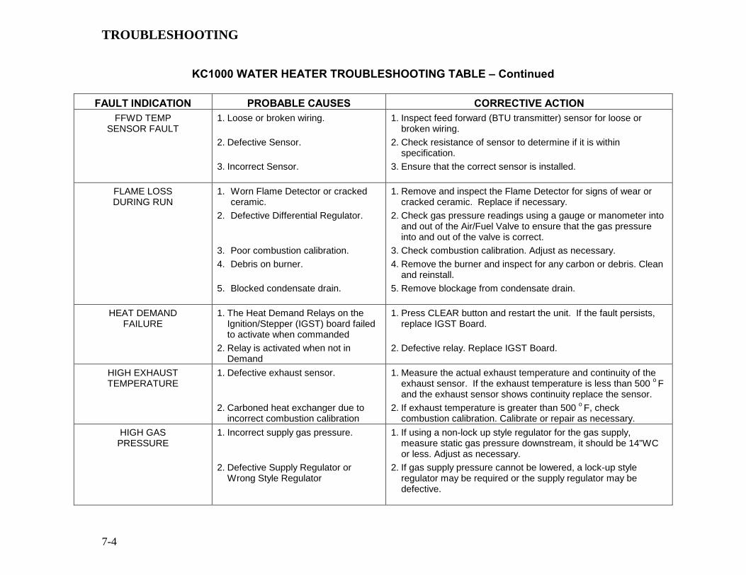
TROUBLESHOOTING
7-4
KC1000 WATER HEATER TROUBLESHOOTING TABLE – Continued
FAULT INDICATION PROBABLE CAUSES CORRECTIVE ACTION
FFWD TEMP SENSOR FAULT
1. Loose or broken wiring.
2. Defective Sensor.
3. Incorrect Sensor.
1. Inspect feed forward (BTU transmitter) sensor for loose or broken wiring.
2. Check resistance of sensor to determine if it is within specification.
3. Ensure that the correct sensor is installed.
FLAME LOSS DURING RUN
1. Worn Flame Detector or cracked ceramic.
2. Defective Differential Regulator.
3. Poor combustion calibration. 4. Debris on burner.
5. Blocked condensate drain.
1. Remove and inspect the Flame Detector for signs of wear or cracked ceramic. Replace if necessary.
2. Check gas pressure readings using a gauge or manometer into and out of the Air/Fuel Valve to ensure that the gas pressure into and out of the valve is correct.
3. Check combustion calibration. Adjust as necessary. 4. Remove the burner and inspect for any carbon or debris. Clean
and reinstall. 5. Remove blockage from condensate drain.
HEAT DEMAND FAILURE
1. The Heat Demand Relays on the Ignition/Stepper (IGST) board failed to activate when commanded
2. Relay is activated when not in Demand
1. Press CLEAR button and restart the unit. If the fault persists, replace IGST Board.
2. Defective relay. Replace IGST Board.
HIGH EXHAUST TEMPERATURE
1. Defective exhaust sensor.
2. Carboned heat exchanger due to incorrect combustion calibration
1. Measure the actual exhaust temperature and continuity of the exhaust sensor. If the exhaust temperature is less than 500 o F and the exhaust sensor shows continuity replace the sensor.
2. If exhaust temperature is greater than 500 o F, check combustion calibration. Calibrate or repair as necessary.
HIGH GAS PRESSURE
1. Incorrect supply gas pressure.
2. Defective Supply Regulator or Wrong Style Regulator
1. If using a non-lock up style regulator for the gas supply, measure static gas pressure downstream, it should be 14”WC or less. Adjust as necessary.
2. If gas supply pressure cannot be lowered, a lock-up style regulator may be required or the supply regulator may be defective.

TROUBLESHOOTING
7-5
KC1000 WATER HEATER TROUBLESHOOTING TABLE – Continued
FAULT INDICATION PROBABLE CAUSES CORRECTIVE ACTION
(continued) 3. Defective High Gas Pressure Switch
3. Remove the leads from the high gas pressure switch and measure continuity across the common and normally closed terminals with the unit not firing. Replace the switch if it does not show continuity.
HIGH WATER TEMP SWITCH OPEN
1. Scaled BTU Transmitter. 2. Faulty Water Temperature Switch.
3. Faulty Temperature Sensor
4. Unit in MANUAL Mode
5. Unit setpoint is greater than Over Temperature Switch setpoint
1. Inspect and clean the BTU transmitter per Maintenance Section. 2. Test the temperature switch to insure it trips at its actual water
temperature setting. 3. Using the resistance charts in Appendix C, measure the
resistance of Shell sensor and BTU sensor at a known water temperature.
4. If unit is in Manual Mode, switch to Auto Mode.
5. Check setpoint of unit and setpoint of Temperature Switch. Ensure that the temperature switch is set 20 degrees higher than the unit’s setpoint.
HIGH WATER TEMPERATURE
1. See HIGH WATER TEMP SWITCH OPEN.
2. Temp HI Limit setting is too low.
1. See HIGH WATER TEMP SWITCH OPEN 2. Check Temp HI Limit Setting.
IGN BOARD COMM FAULT
1. Communication fault has occurred between the PMC board and Ignition/Stepper (IGST) board
1. Press CLEAR button and restart unit. If fault persists, contact qualified Service Personnel.

TROUBLESHOOTING
7-6
KC1000 WATER HEATER TROUBLESHOOTING TABLE – Continued
FAULT INDICATION PROBABLE CAUSES CORRECTIVE ACTION IGN SWTCH CLOSED
DURING PURGE 1. Air/Fuel Valve not rotating
2. Defective or shorted switch
3. Switch wired incorrectly
4. Defective Power Supply Board or fuse
5. Defective IGST Board
1. Start the unit. The Air/Fuel Valve should rotate to the purge (open) position. If the valve does not rotate at all or does not rotate fully open, check the Air/Fuel Valve calibration. If calibration is okay, the problem may be in the Air-Fuel Valve or the Control Box. Refer to qualified service personnel.
2. If the Air/Fuel Valve does rotate to purge, check the ignition switch for continuity between the N.O. and COM terminals. If the switch shows continuity when not in contact with the cam replace the switch.
3. Check to ensure that the switch is wired correctly (correct wire numbers on the normally open terminals). If the switch is wired correctly, replace the switch
4. Check DS1 & DS2 LEDs on Power Supply Board. If they are not steady ON, replace Power Supply Board.
5. Check “Heartbeat” LED DS1 and verify it is blinking ON & OFF every second. If not, replace IGST Board.
IGN SWTCH OPEN DURING IGNITION
1. Air/Fuel Valve not rotating to ignition position.
2. Defective ignition switch
3. Defective Power Supply Board or fuse
4. Defective IGST Board
1. Start the unit. The Air/Fuel Valve should rotate to the purge (open) position, then back to ignition position (towards closed) during the ignition cycle. If the valve does not rotate back to the ignition position, check the Air/Fuel Valve calibration. If calibration is okay, the problem may be in the Air/Fuel Valve or the Control Box. Refer fault to qualified service personnel.
2. If the Air/Fuel Valve does rotate to the ignition position, check the ignition position switch for continuity between the N.O. and COM terminals when in contact with the cam.
3. Check DS1 & DS2 LEDs on Power Supply Board. If they are not steady ON, replace Power Supply Board.
4. Check “Heartbeat” LED DS1 and verify it is blinking ON & OFF every second. If not, replace IGST Board.
INTERLOCK OPEN
1. Interlock jumper not installed or removed
2. Energy Management System does not have boiler enabled.
3. Device proving switch hooked to interlocks is not closed.
1. Check for a jumper properly installed across the interlock terminals in the I/O box
2. If there are two external wires on these terminals check any Energy Management system to see if they have the units disabled (a jumper may be temporarily installed to see if the interlock circuit is functioning).
3. Check that proving switch for any device hooked to the interlock circuit is closing and that the device is operational.
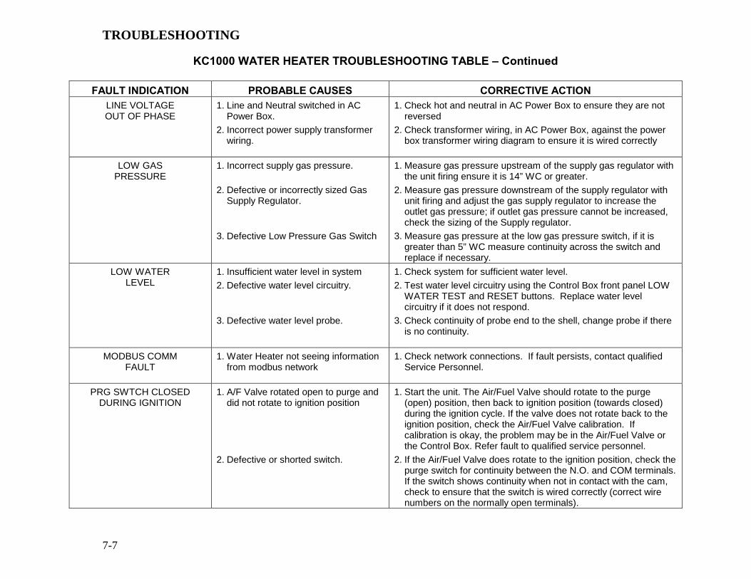
TROUBLESHOOTING
7-7
KC1000 WATER HEATER TROUBLESHOOTING TABLE – Continued
FAULT INDICATION PROBABLE CAUSES CORRECTIVE ACTION LINE VOLTAGE OUT OF PHASE
1. Line and Neutral switched in AC Power Box.
2. Incorrect power supply transformer wiring.
1. Check hot and neutral in AC Power Box to ensure they are not reversed
2. Check transformer wiring, in AC Power Box, against the power box transformer wiring diagram to ensure it is wired correctly
LOW GAS PRESSURE
1. Incorrect supply gas pressure.
2. Defective or incorrectly sized Gas Supply Regulator.
3. Defective Low Pressure Gas Switch
1. Measure gas pressure upstream of the supply gas regulator with the unit firing ensure it is 14” WC or greater.
2. Measure gas pressure downstream of the supply regulator with unit firing and adjust the gas supply regulator to increase the outlet gas pressure; if outlet gas pressure cannot be increased, check the sizing of the Supply regulator.
3. Measure gas pressure at the low gas pressure switch, if it is greater than 5” WC measure continuity across the switch and replace if necessary.
LOW WATER LEVEL
1. Insufficient water level in system 2. Defective water level circuitry.
3. Defective water level probe.
1. Check system for sufficient water level. 2. Test water level circuitry using the Control Box front panel LOW
WATER TEST and RESET buttons. Replace water level circuitry if it does not respond.
3. Check continuity of probe end to the shell, change probe if there is no continuity.
MODBUS COMM FAULT
1. Water Heater not seeing information from modbus network
1. Check network connections. If fault persists, contact qualified Service Personnel.
PRG SWTCH CLOSED DURING IGNITION
1. A/F Valve rotated open to purge and did not rotate to ignition position
2. Defective or shorted switch.
1. Start the unit. The Air/Fuel Valve should rotate to the purge (open) position, then back to ignition position (towards closed) during the ignition cycle. If the valve does not rotate back to the ignition position, check the Air/Fuel Valve calibration. If calibration is okay, the problem may be in the Air/Fuel Valve or the Control Box. Refer fault to qualified service personnel.
2. If the Air/Fuel Valve does rotate to the ignition position, check the purge switch for continuity between the N.O. and COM terminals. If the switch shows continuity when not in contact with the cam, check to ensure that the switch is wired correctly (correct wire numbers on the normally open terminals).

TROUBLESHOOTING
7-8
KC1000 WATER HEATER TROUBLESHOOTING TABLE – Continued
FAULT INDICATION PROBABLE CAUSES CORRECTIVE ACTION (continued) 3. Switch wired incorrectly.
4. Defective Power Supply Board or fuse
5. Defective IGST Board
3. If the switch is wired correctly, replace the switch. 4. Check DS1 & DS2 LEDs on Power Supply Board. If they are not
steady ON, replace Power Supply Board. 5. Check “Heartbeat” LED DS1 and verify it is blinking ON & OFF
every second. If not, replace IGST Board. PRG SWTCH OPEN
DURING PURGE 1. Defective purge switch.
2. No voltage present at switch.
3. Switch wired incorrectly.
4. Defective Power Supply Board or fuse
5. Defective IGST Board
1. If the air-fuel valve does rotate, check the purge switch for continuity when closing. Replace switch if continuity does not exist.
2. Measure for 24 VAC from each side of the switch to ground. If 24VAC is not present, refer fault to qualified service personnel.
3. Check to ensure that the switch is wired correctly (correct wire numbers on the normally open terminals).
4. Check DS1 & DS2 LEDs on Power Supply Board. If they are not steady ON, replace Power Supply Board.
5. Check “Heartbeat” LED DS1 and verify it is blinking ON & OFF every second. If not, replace IGST Board.
REMOTE SETPT SIGNAL FAULT
1. Remote setpoint signal not present: Not yet installed. Wrong polarity. Signal defective at source. Broken or loose wiring.
2. Signal is not isolated (floating) if 4 to 20 mA.
3. Control Box signal type selection switches not set for correct signal type (voltage or current).
1. Check I/O Box to ensure signal is hooked up. Hook up if not installed. If installed, check polarity. Measure signal level. Check continuity of wiring between source and boiler.
2. Check signal at source to ensure it is isolated.
3. Check DIP switch on PMC board to ensure it is set correctly for the type of signal being sent. Check control signal type set in Configuration Menu.
RESIDUAL FLAME
1. SSOV not fully closed.
2. Defective Flame Detector.
1. Check open/close indicator window of Safety Shut-Off Valve (SSOV) and ensure that the SSOV is fully closed. If not fully closed, replace the valve and or actuator. Close gas shut-off valve downstream of SSOV. Install a manometer or gauge in a gas test port between the SSOV and the gas shut off valve. If a gas pressure reading is observed replace the SSOV valve and or actuator.
2. Replace Flame Detector.
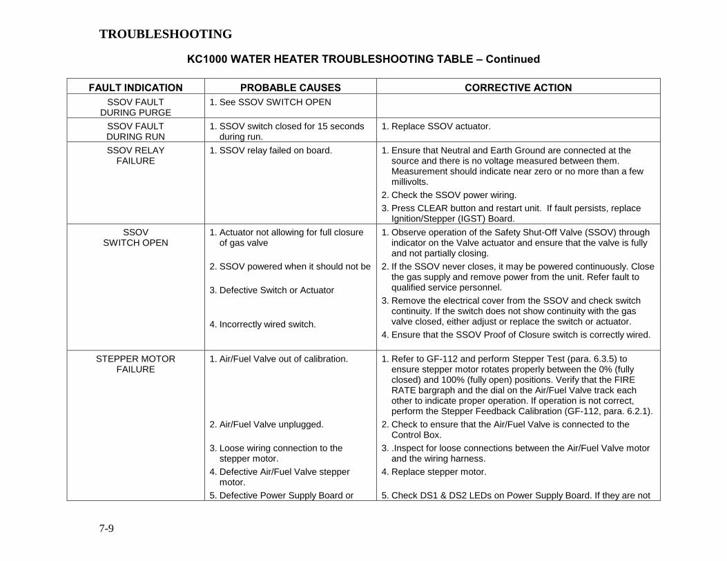
TROUBLESHOOTING
7-9
KC1000 WATER HEATER TROUBLESHOOTING TABLE – Continued
FAULT INDICATION PROBABLE CAUSES CORRECTIVE ACTION SSOV FAULT
DURING PURGE 1. See SSOV SWITCH OPEN
SSOV FAULT DURING RUN
1. SSOV switch closed for 15 seconds during run.
1. Replace SSOV actuator.
SSOV RELAY FAILURE
1. SSOV relay failed on board. 1. Ensure that Neutral and Earth Ground are connected at the source and there is no voltage measured between them. Measurement should indicate near zero or no more than a few millivolts.
2. Check the SSOV power wiring. 3. Press CLEAR button and restart unit. If fault persists, replace
Ignition/Stepper (IGST) Board. SSOV
SWITCH OPEN 1. Actuator not allowing for full closure
of gas valve
2. SSOV powered when it should not be
3. Defective Switch or Actuator
4. Incorrectly wired switch.
1. Observe operation of the Safety Shut-Off Valve (SSOV) through indicator on the Valve actuator and ensure that the valve is fully and not partially closing.
2. If the SSOV never closes, it may be powered continuously. Close the gas supply and remove power from the unit. Refer fault to qualified service personnel.
3. Remove the electrical cover from the SSOV and check switch continuity. If the switch does not show continuity with the gas valve closed, either adjust or replace the switch or actuator.
4. Ensure that the SSOV Proof of Closure switch is correctly wired.
STEPPER MOTOR FAILURE
1. Air/Fuel Valve out of calibration.
2. Air/Fuel Valve unplugged.
3. Loose wiring connection to the stepper motor.
4. Defective Air/Fuel Valve stepper motor.
5. Defective Power Supply Board or
1. Refer to GF-112 and perform Stepper Test (para. 6.3.5) to ensure stepper motor rotates properly between the 0% (fully closed) and 100% (fully open) positions. Verify that the FIRE RATE bargraph and the dial on the Air/Fuel Valve track each other to indicate proper operation. If operation is not correct, perform the Stepper Feedback Calibration (GF-112, para. 6.2.1).
2. Check to ensure that the Air/Fuel Valve is connected to the Control Box.
3. .Inspect for loose connections between the Air/Fuel Valve motor and the wiring harness.
4. Replace stepper motor.
5. Check DS1 & DS2 LEDs on Power Supply Board. If they are not

TROUBLESHOOTING
7-10
fuse 6. Defective IGST Board
steady ON, replace Power Supply Board. 6. Check “Heartbeat” LED DS1 and verify it is blinking ON & OFF
every second. If not, replace IGST Board.

APPENDIX A
A-1
WATER HEATER MENU ITEM DESCRIPTIONS
MENU LEVEL & FUNCTION DESCRIPTION
OPERATING MENU
Active Setpoint This is the setpoint temperature to which the control is operating when operating in the Constant Setpoint or Remote Setpoint Mode. When in the Constant Setpoint Mode, this value is equal to the Internal Setpoint setting in the Configuration Menu. When in the Remote Setpoint Mode, this value is the setpoint equivalent to the remote analog signal supplied to the unit.
Aux Temp For monitoring purposes only
Outdoor Temp Displayed only if outdoor sensor is enabled in the Configuration Menu.
Flow Rate Flow rate in GPM is displayed only if flow sensor is enabled.
Fire Rate Out Actual fire rate as shown on bar-graph. This function must be factory-enabled.
Flame Strength Displays flame strength from 0 to 100%.
Run Cycles Displays the total number of run cycles from 0 to 999,999.
Run Hours Displays total run time of unit in hours from 0 to 999,999.
Fault Log Displays information on the last 9 faults.

APPENDIX A
A-2
WATER HEATER MENU ITEM DESCRIPTIONS - Continued
MENU LEVEL & OPTION DESCRIPTION
SETUP MENU
Password Allows password to be entered.
Once the valid password (159) is entered, options in the Setup, Configuration and Tuning Menus can be modified.
Language English Only
Time Displays time from 12:00am to 11:59pm.
Date Displays dates from 01/01/00 to 12/31/99
Unit of Temp Permits selection of temperature displays in degrees Fahrenheit (°F) or degrees Celsius (°C). Default is °F.
Comm Address For RS-485 communications (0 to 127). Default address is 0. RS-232 should have its own (programmable) password.
Baud Rate Allows communications Baud Rate to be set (2400 to 19.2K). Default is 9600.
Software Version Identifies the current software version of the control box (Ver 0.00 to Ver 9.99).

APPENDIX A
A-3
WATER HEATER MENU ITEM DESCRIPTIONS - Continued
MENU LEVEL & OPTION DESCRIPTION
CONFIGURATION MENU
Internal Setpoint Allows internal setpoint to be set. Default is 130°F.
Unit Type Allows selection of Boiler or Water Heater.
Unit Size Sets unit size from 0.5 to 3.0 MBTUs. Default is 1.0 MBTU.
Heater Mode It allows selection of either the Constant Setpoint or Remote Setpoint Mode. Default is Constant Setpoint.
Remote Signal Used to set the type of external signal which will be used when operating in the Remote Setpoint Mode. The factory default is 4-20 mA/1-5V.
Setpoint Lo Limit Used to set the minimum allowable setpoint (40°F to Setpoint Hi Limit). Default is 60°F
Setpoint Hi Limit Used to set the maximum allowable setpoint (Setpoint Lo Limit to 240°F). Default is 200°F.
Temp Hi Limit This is the maximum allowable outlet temperature (30 to 230°F). Any temperature above this setting will turn off the unit. The temperature must then drop 5° below this setting to allow the unit to run. Default Hi Limit is 215°F.
Max Fire Rate Sets the maximum allowable fire rate for the unit (40% to 100%). Default is 100%.
Aux Start On Dly Specifies the amount of time to wait (0 to 120 sec.) between activating the Aux Relay (due to a demand) and checking the pre-purge string to start the boiler. Default is 0 sec.
Failsafe Mode Allows the Failsafe mode to be set to either Constant Setpoint or Shutdown. Default is Shutdown.
mA Output Can be set to allow this output to monitor Setpoint, Outlet Temperature, Fire Rate Out, or be set to OFF. Default is OFF.
Lo Fire Timer Specifies how long (2 to 120 sec.) to remain in the low fire position after ignition, before going to the desired output. Default is 2 sec.
Setpt Limiting Allows Setpt Limiting to be enabled or disabled. Default is disabled.
Setpt Limit Band When Setpt Limiting is enabled, this menu item allows the Setpt Limit Band to be set from 0°F to 10°F. Default is 5°F.

APPENDIX A
A-4
WATER HEATER MENU ITEM DESCRIPTIONS - Continued
MENU LEVEL & OPTION DESCRIPTION
TUNING MENU
Prop Band Generates a fire rate based on the error that exists between the setpoint temperature and the actual outlet temperature. If the actual error is less than the proportional band setting (1 to 120°F), the fire rate will be less than 100%. If the error is equal to or greater than the proportional band setting, the fire rate will be 100%. (Default is 8°F for a Water Heater)
Integral Gain This sets the fraction of the output, due to setpoint error, to add or subtract from the output each minute to move towards the setpoint. Gain is adjustable from 0.00 to 2.00 (Default is 1.60 for a Water Heater).
Derivative Time This value (0.0 to 2.0 min.) responds to the rate of change of the setpoint error. This is the time that this action advances the output. (Default is 0.10 min. for a Water Heater)
Min Load Adj Setting is adjustable from -50°F to +50°F (Default is zero). It adjusts the output by adding an offset to the breakpoint chart at minimum flow. This is used to fine tune Feed-Forward (FFWD) output at low flow levels.
Max Load Adj Setting is adjustable from -50°F to +50°F (Default is zero). It adjusts the output by changing the scaling of the breakpoint chart at maximum flow.
FFWD Temp Displays the Feed-Forward temperature.
Outlet Feedback Used to Enable or Disable feedback. Disable this function for Feed-Forward control only.
Feedback Gain* Adjustable from 0.01 to 1.00 (Default is 0.05).
Breakpoint at 100%
Thru
Breakpoint at 0%
Allows breakpoint temperature settings (30°F to 240°F) to be entered for 100% to 0% in 10% increments. See Appendix D for default values.
Reset Defaults? Allows all Tuning Menu items to be reset to their Factory Default values.
*Only displayed when Heater Tuning Display is enabled by factory authorized personnel.

APPENDIX B
B-1
STARTUP, STATUS AND FAULT MESSAGES
STARTUP AND STATUS MESSAGES
MESSAGE DESCRIPTION DISABLED
HH:MM pm MM/DD/YY Displayed if ON/OFF switch is set to OFF. The display also shows the time and date that the unit was disabled.
STANDBY Displayed when ON/OFF switch is in the ON position, but there is no demand for heat. The time and date are also displayed.
DEMAND DELAY XX sec
Displayed if Demand Delay is active.
PURGING XX sec
Displayed during the purge cycle during startup. The duration of the purge cycle counts up in seconds.
IGNITION TRIAL XX sec
Displayed during ignition trial of startup sequence. The duration of cycle counts up in seconds.
FLAME PROVEN
Displayed after flame has been detected for a period of 2 seconds. Initially, the flame strength is shown in %. After 5 seconds has elapsed, the time and date are shown in place of flame strength.
WARMUP XX sec
Displayed for 2 minutes during the initial warmup only.
WAIT Prompts the operator to wait.

APPENDIX B
B-2
FAULT MESSAGES
FAULT MESSAGE FAULT DESCRIPTION HIGH WATER TEMP
SWITCH OPEN The High Water Temperature Limit Switch is open.
LOW WATER LEVEL
The Water Level Control board is indicating low water level.
LOW GAS PRESSURE
The Low Gas Pressure Limit Switch is open.
HIGH GAS PRESSURE
The High Gas Pressure Limit Switch is open.
INTERLOCK OPEN
The Remote Interlock is open.
DELAYED INTERLOCK OPEN
The Delayed Interlock is open.
AIRFLOW FAULT DURING PURGE
The Blower Proof Switch opened during purge.
PRG SWTCH OPEN DURING PURGE
The Purge Position Limit switch on the air/fuel valve opened during purge.
IGN SWTCH OPEN DURING IGNITION
The Ignition Position Limit switch on the air/fuel valve opened during ignition.
IGN SWTCH CLOSED DURING PURGE
The Ignition Position Limit switch on the air/fuel valve closed during purge.
PRG SWTCH CLOSED DURING IGNITION
The Purge Position Limit switch on the air/fuel valve closed during ignition.
AIRFLOW FAULT DURING IGN
The Blower Proof Switch opened during ignition.
AIRFLOW FAULT DURING RUN
The Blower Proof Switch opened during run.
SSOV SWITCH OPEN
The SSOV switch opened during standby.
SSOV FAULT DURING PURGE
The SSOV switch opened during purge.
SSOV FAULT DURING IGN
The SSOV switch closed or failed to open during ignition.
SSOV FAULT DURING RUN
The SSOV switch closed for more than 15 seconds during run.
SSOV RELAY FAILURE
A failure has been detected in one of the relays that control the SSOV.
FLAME LOSS DURING IGN
The Flame signal was not seen during ignition or lost within 5 seconds after ignition.
FLAME LOSS DURING RUN
The Flame signal was lost during run.
HIGH EXHAUST TEMPERATURE
The High Exhaust Temperature Limit Switch is closed.
LOSS OF POWER
A power loss had occurred. The time and date when power was restored is displayed.

APPENDIX B
B-3
FAULT MESSAGES - Continued
FAULT MESSAGE FAULT DESCRIPTION RESIDUAL
FLAME The Flame signal was seen for more than 60 seconds during standby.
HEAT DEMAND FAILURE
The Heat Demand Relays on the Ignition board failed to activate when commanded.
IGN BOARD COMM FAULT
A communication fault has occurred between the CPU board and Ignition board.
DIRECT DRIVE SIGNAL FAULT
The direct drive signal is not present or is out of range.
REMOTE SETPT SIGNAL FAULT
The remote setpoint signal is not present or is out of range.
OUTDOOR TEMP SENSOR FAULT
The temperature measured by the Outdoor Air Sensor is out of range.
OUTLET TEMP SENSOR FAULT
The temperature measured by the Outlet Sensor is out of range.
FFWD TEMP SENSOR FAULT
The temperature measured by the FFWD Sensor is out of range.
HIGH WATER TEMPERATURE
The temperature measured by the Outlet Sensor exceeded the Temp Hi Limit setting.
LINE VOLTAGE OUT OF PHASE
The High AC voltage is out of phase from the low AC voltage.
STEPPER MOTOR FAILURE
The stepper motor failed to move the valve to the desired position.
NETWORK COMM FAULT
The RS-485 network information is not present or is corrupted.


APPENDIX C
C-1
Temperature Sensor Resistance Chart (Balco)

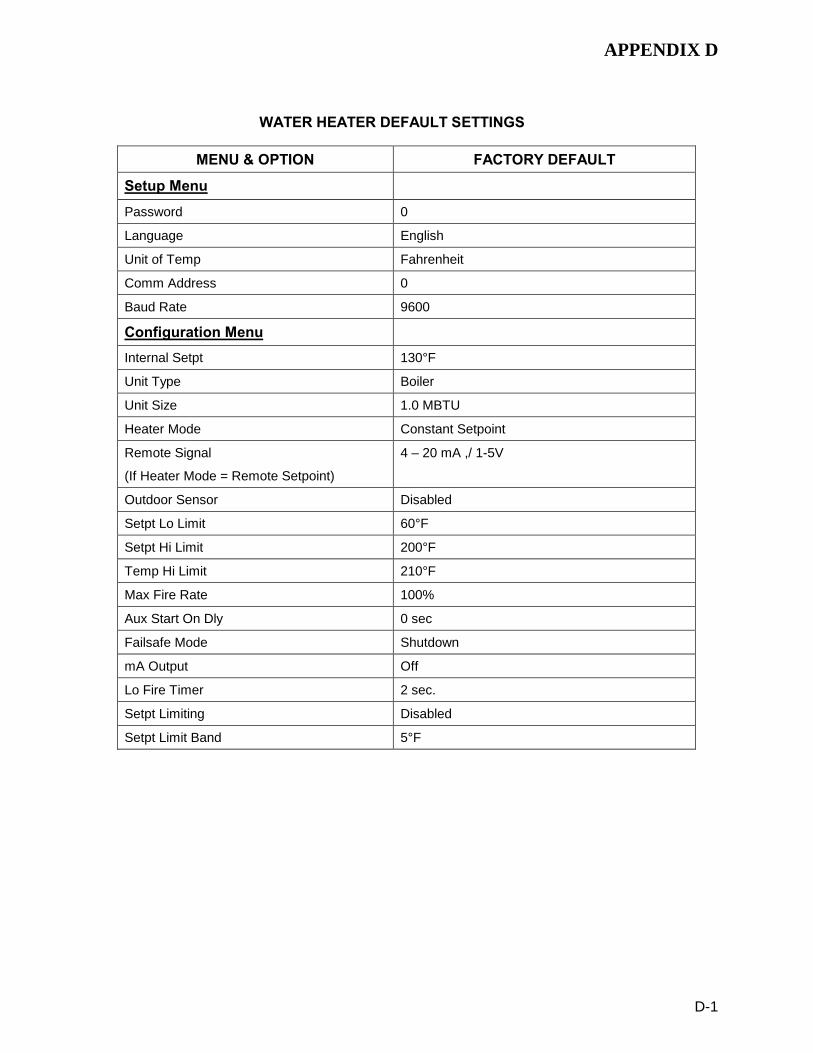
APPENDIX D
D-1
WATER HEATER DEFAULT SETTINGS
MENU & OPTION FACTORY DEFAULT
Setup Menu
Password 0
Language English
Unit of Temp Fahrenheit
Comm Address 0
Baud Rate 9600
Configuration Menu Internal Setpt 130°F
Unit Type Boiler
Unit Size 1.0 MBTU
Heater Mode Constant Setpoint
Remote Signal
(If Heater Mode = Remote Setpoint)
4 – 20 mA ,/ 1-5V
Outdoor Sensor Disabled
Setpt Lo Limit 60°F
Setpt Hi Limit 200°F
Temp Hi Limit 210°F
Max Fire Rate 100%
Aux Start On Dly 0 sec
Failsafe Mode Shutdown
mA Output Off
Lo Fire Timer 2 sec.
Setpt Limiting Disabled
Setpt Limit Band 5°F

APPENDIX D
D-2
WATER HEATER DEFAULT SETTINGS - Continued
MENU & OPTION FACTORY DEFAULT
Tuning Menu Prop Band 8°F
Integral Gain 1.60
Derivative Time 0.10 min
Min Load Adj 0°F
Max Load Adj 0°F
FFWD Temp N/A
Outlet Feedback On
Feedback Gain 0.05
Breakpoint At 100% 77°F
Breakpoint At 90% 81°F
Breakpoint At 80% 85°F
Breakpoint At 70% 91°F
Breakpoint At 60% 95°F
Breakpoint At 50% 102°F
Breakpoint At 40% 110°F
Breakpoint At 30% 112°F
Breakpoint At 20% 114°F
Breakpoint At 10% 130°F
Breakpoint At 0% 135°F
Reset Defaults? No

APPENDIX E
E-1
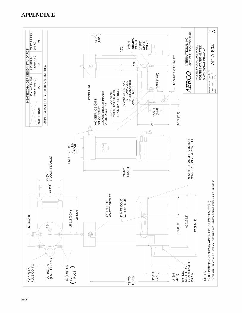
APPENDIX E
E-2
18(4
5.7)
49 (1
24.5
)
57 (1
44.8
)
16-3
/4
22-5
/8
71-7
/8
71-7
/8
19 (4
8)
15-1
/2 (3
9.4)
6 (1
5.2)
I.D
.FL
UE
CO
NN
.
3/4
(1.9
) DIA
.
(EN
CLO
SU
RE
)
PR
ES
S./T
EM
P.
RE
LIE
F
2" N
PT
HO
T
2" N
PT
CO
LD
3-1/
8 (7
.9)
(182
.6)
5-3/
4 (1
4.6)
RE
MO
TE A
LAR
M &
CO
NTR
OL
CO
NN
EC
TIO
N -
3/4
CO
ND
UIT
1-1/
4 N
PT
GA
S IN
LET
(182
.6)
(57.
5)
(42.
5)
LIFT
ING
LU
G
VA
LVE
1"N
PT
DR
AIN
VA
LVE
5/8"
I.D
.M
ALE
HO
SE
CO
ND
EN
SA
TED
RA
IN
2"N
PT
RE
CIR
CC
ON
N.
1) A
LL D
IME
NS
ION
S S
HO
WN
AR
E IN
INC
HE
S (C
EN
TIM
ETE
RS
)A
P-A
-804
NO
TES
:
PO
TAB
LE W
ATE
R H
EA
TER
INTE
RN
ATI
ON
AL
INC
.
1:24
P.K
./G.K
.D
ATE
DW
N B
Y
SIZ
ES
CA
LE
AP
PD
CH
KD
B
WA
TER
OU
TLE
T
WA
TER
INLE
T
29
3 (8
)
c.g.
INLE
T A
DA
PTE
R
CO
MB
. AIR
INTA
KE
AERC
ON
OR
THV
ALE
, NE
W J
ER
SE
Y 0
7647
MO
DE
L K
C10
00 G
AS
FIR
ED
22-1
/4 (5
7)
47 (1
19.4
)
22 (5
6)(F
LOO
R F
LAN
GE
)
2) D
RA
IN V
ALV
E &
RE
LIE
F V
ALV
E A
RE
INC
LUD
ED
SE
PA
RA
TELY
IN S
HIP
ME
NT
A2-
1-95
DIM
EN
SIO
NA
L D
RA
WIN
G
AC
SE
RV
ICE
C0N
N.
3/4
CO
ND
UIT
120V
AC
SIN
GLE
PH
AS
E20
AM
P W
/GR
D
35 (8
9)
TYP
.4-
PLC
S(
)
c.g.
78-1
/2(1
99.4
)
13-9
/16
(34.
4)
3/4"
NP
T G
AS
VE
NT
CO
NN
. FO
R "I
RI G
AS
TRA
IN O
PTI
ON
" ON
LY
(OP
TIO
NA
L O
.A.
AV
AIL
. - 6
" OD
)
HE
AT
EX
CH
AN
GE
R D
ES
IGN
STA
ND
AR
DS
MA
XIM
UM
TEM
P. (
°F)
AS
ME
B &
PV
CO
DE
SE
CTI
ON
IV S
TAM
P H
LW
SH
ELL
SID
E
PR
ES
S. (
PS
IG)
155
MA
X. W
OR
KIN
GTE
ST
PR
ES
S.
(PS
IG)
210
233
RE
V.
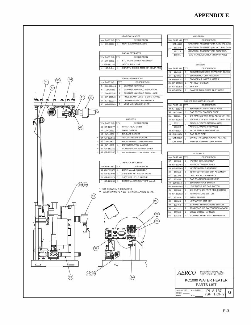
APPENDIX E
E-3
1/8" NPT x 3/8" O.D. TUBE AL. COMP. FTG.
3/8" NPT x 3/8" O.D. TUBE AL. COMP. FTG.
32 GP-122614 1
29
35
31
GM-20934 1
123581
GP-161146
1
1 BLOWER TO AIR VA. INLET HOSE
GAS INLET PIPE
30
34
GP-18894 1
GP-161147 1
GAS PRESS. CONTROL TUBE
VALVE TO BURNER AIR HOSE
33201211
1AIR/FUEL VALVE (NATURAL GAS)
36 GM-20874 1BURNER ASSEMBLY (NATURAL GAS)
28 GP-122561 1 DAMPER TO BLOWER INLET HOSE
27 GP-122835 2 SPACER
26 GP-122669 1 AIR INLET SCREEN
25 GP-161152 1
23 124935 1
BLOWER AIR INLET SHUTTER
BLOWER (INCLUDES CAPACITOR 124936)
1/4" MNPT x 1/8" FNPT RED. BUSHING
44
45
GP-122403
123536
1
1
LOW PRESSURE GAS SWITCH
EXH. MANIFOLD TO COMB. CHAMB. GASKET18 GP-122537 1
EXH. MANIFOLD TO LOWER HEAD SEAL
17 GP-161151 1
15
16 1GP-18899
GP-18900 1
COMBUSTION CHAMBER LINER
BURNER FLANGE GASKET
14 GP-122551 1 TEFLON RELEASE GASKET
21
20
19
GP-122608
GP-122573 1
1
GM-122828 1
1-1/2" NPT P&T RELIEF VALVE
1-1/2" NPT x 3" LG. NIPPLE
DRAIN VALVE ASSEMBLY
1/4"NPT x 3/8"O.D. TUBE 90° COMP. FTG.4 GP-8-3-1 1
EXHAUST MANIFOLD
ITEM QTYPART NO. DESCRIPTION
HOSE CLAMP 13/16" - 1-3/4"∅ RANGE
1GM-1233527 EXHAUST MANIFOLD DRAIN HOSE
8 GP-122540 1
5
6 GP-20885
GM-20844-2
1
1
EXHAUST MANIFOLD INSULATION
EXHAUST MANIFOLD
46 GP-122822 1 TEMPERATURE SWITCH
43 61002-14 1
38
2
41
GM-20872 1
181198
GP-122464
1
1
BLOWER PROOF SWITCH
CONTROL BOX ASSEMBLY
BTU TRANSMITTER ASSEMBLY
IGNITION TRANSFORMER
BLOWER MOTOR CAPACITOR24 124936 1
22 24
37
19
38
46
21 20
25
26
4544
48
47
49 123463 EXHAUST TEMPERATURE SWITCH1
47 123448 SHELL SENSOR1
48 122843 LOW WATER CUT-OFF1
GP-161145 HOT SUPPLY LINE13
16155937 POWER BOX ASSEMBLY1
PART NO.ITEM QTY
LOAD-ALERT PARTS
DESCRIPTION
PART NO.ITEM QTY
OTHER ACCESSORIES
DESCRIPTION
PART NO.ITEM QTY
CONTROLS
DESCRIPTION
PART NO.ITEM QTY
BLOWER
DESCRIPTION
PART NO.ITEM QTY
BURNER AND AIR/FUEL VALVE
DESCRIPTION
ITEM
HEAT EXCHANGER
PART NO. QTY DESCRIPTION
HEAT EXCHANGER ASS'Y1 GM-20881 1
UPPER HEAD LINER
SHELL GASKET
RELEASE GASKET
GP-123077
GP-18532
GP-18556
11
12
13
2
1
1
DESCRIPTIONPART NO.ITEM QTY
GASKETS
39 GP-122569 1 IGNITION CABLE ASSEMBLY
GAS TRAIN WIRING HARNESS116145042
39
40 161560 1 INPUT/OUTPUT (I/O) BOX ASSEMBLY
CONDENSATE CUP ASSEMBLYGP-1233379 1
VENT MOUNTING FLANGEGP-12284910 2
23
* GP-123050 1 EXTERNAL GAS SHUT-OFF VALVE
* - NOT SHOWN IN THE DRAWING
TEMPERATURE SWITCH THERMOWELL12371150 2
50
SHELL WIRING HARNESS
EXHAUST TEMP. SWITCH HARNESS52
51
124334
161569
1
1
**
**
**
**
**
** - SEE DRAWING PL-A-136 FOR INSTALLATION DETAIL
51
KC1000 WATER HEATERPARTS LIST
DATE
DATESCALEAPPD.
DWN.BY CZ
(SH. 1 OF 2)PL-A-137041304
G
NORTHVALE, NJ 07647INTERNATIONAL, INC.AERCO
GAS TRAIN ASSEMBLY (IRI; NATURAL GAS)
GAS TRAIN ASSEMBLY (FM; NATURAL GAS)GM-18997
PART NO.
22
ITEM
1811821
QTY DESCRIPTION
GAS TRAIN
BURNER ASSEMBLY (PROPANE)GM-20933
201222 AIR/FUEL VALVE (PROPANE)
GAS TRAIN ASSEMBLY (FM; PROPANE)
GAS TRAIN ASSEMBLY (IRI; PROPANE)181191
181123

APPENDIX E
E-4
14
36
3516 34
7
15
18
17
1
6
10
33 29
32 31 30
40
241
3
4
27 28
49
43
SEE DETAIL "A"
EXPLODEDDETAIL "A"
13
12
11
42
9
5
8
SEE DRAWING PL-A-134 FOR AVAILABLE PARTS
52
AERCOKC1000 WATER HEATER
CZDWN.BY
APPD.SCALE
041304DATE
(SH. 2 OF 2)PL-A-137
DATEG
INTERNATIONAL, INC.NORTHVALE, NJ 07647
PARTS LIST

APPENDIX E
E-5
1 1/
2" S
AFE
TY S
HU
T-O
FF V
ALV
E
DIF
FER
EN
TIA
L P
RE
SS
UR
E R
EG
ULA
TOR
W/ B
RO
WN
SP
RIN
G
BU
RN
ER
/GA
S V
A. A
DA
PTO
R
2 3 4 51
GM
-161
095
GA
S C
OC
K
GP
-122
415
GP
-122
409
11
1241
501
53
42
1
1
1241
381
SS
OV
AC
TUA
TOR
FRO
NT
VIE
WLE
FT S
IDE
VIE
WR
EA
R V
IEW
DE
SC
RIP
TIO
NIT
EM
PA
RT
NO
.RE
Q
PA
RTS
LIS
T
AERC
OIN
TER
NA
TIO
NA
L, IN
C.
NO
RTH
VA
LE, N
J 0
7647
(FA
CTO
RY
MU
TUA
L)
AP
PD
.S
CA
LED
ATE
CZ
DW
N.B
YD
ATE
0430
02
PL-
A-1
35DR
EV
.
6
7
GP
-122
548
61
SP
RIN
G (B
RO
WN
) FO
R D
IFFE
RE
NTI
AL
PR
ES
SU
RE
RE
GU
LATO
R
- TH
E S
EC
ON
D O
-RIN
G (N
OT
SH
OW
N IN
TH
E D
RA
WIN
G) G
OE
S T
O T
HE
GA
S O
UTL
ET
FLA
NG
E O
F TH
E A
IR-F
UE
L V
ALV
E.
*
GA
S T
RA
IN O
-RIN
G*
GP
-122
406
27
RIG
HT
SID
E V
IEW
KC
1000
NA
T. G
AS
TR
AIN
AS
SE
MB
LY
8
8 9G
P-1
2240
3G
P-1
2241
2
1 1LO
W G
AS
PR
ES
SU
RE
SW
ITC
H
HIG
H G
AS
PR
ES
SU
RE
SW
ITC
H
* *** * *
- WH
EN
OR
DE
RIN
G G
AS
TR
AIN
AS
SE
MB
LIE
S, T
HE
GA
S P
RE
SS
UR
E S
WIT
CH
IS O
RD
ER
ED
SE
PA
RA
TELY
9"F
OR
BO
ILE
R O
NLY
" R
EF
LOC
ATI
ON
OF
HIG
H G
AS
P
RE
SS
UR
E S
WIT
CH
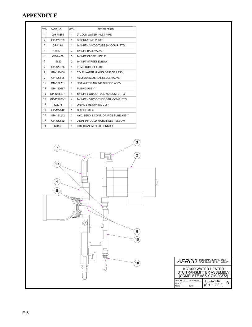
APPENDIX E
E-6
5
4
13
7
18
16
6
2
3
1/4"NPT x 3/8"OD TUBE 90° COMP. FTG.
PUMP OUTLET TUBE
1/4"NPT STREET ELBOW
1/4"NPT CLOSE NIPPLE
1/4"NPT BALL VALVE
CIRCULATING PUMP
2" COLD WATER INLET PIPE1 GM-18859 1
GP-122756
GP-9-430
12820-1
GP-8-3-1
GP-1227592
4
3
6
5
7
1
1
3
12823 2
3
1
2"NPT 90° COLD WATER INLET ELBOW
HYD. ZERO & CONT. ORIFICE TUBE ASS'Y
1/4"NPT x 3/8"OD TUBE STR. COMP. FTG.
1/4"NPT x 3/8"OD TUBE 45° COMP. FTG.
HOT WATER MIXING ORIFICE ASS'Y
COLD WATER MIXING ORIFICE ASS'Y
BTU TRANSMITTER SENSOR
ORIFICE DISC
ORIFICE RETAINING CLIP
TUBING ASS'Y
HYDRAULIC ZERO NEEDLE VALVE
122075
GP-122677-1
GP-122613-1
GM-122687
GM-122761
GP-122506
GM-122400
11
9
8
10
12
14
13
1
1
1
1
1
4
1
123449
GP-122552
GM-161212
GP-122512
16
15
17
18
1
1
1
1
ITEM QTY.PART NO. DESCRIPTION
NORTHVALE, NJ 07647
(SH. 1 OF 2)PL-A-134
KC1000 WATER HEATERBTU TRANSMITTER ASSEMBLY(COMPLETE ASS’Y GM-20872)
INTERNATIONAL, INC.
SCALE
APPD.
DWN.BY 041304CZ
DATE
DATE
AERCO
B

APPENDIX E
E-7
17
14
J
15
1
5
9
8
4
5
11
10
413
12
NORTHVALE, NJ 07647
(SH. 2 OF 2)PL-A-134
KC1000 WATER HEATERBTU TRANSMITTER ASSEMBLY(COMPLETE ASS’Y GM-20872)
INTERNATIONAL, INC.
SCALE
APPD.
DWN.BY 041304CZ
DATE
DATE
AERCO
B

APPENDIX E
E-8
DW
N.B
YS
CA
LEA
PP
D.
KC
1000
WA
TER
HE
ATE
RIR
I GA
S T
RA
IN
SD
-A-6
0603
0801
PD
RD
ATE
DA
TEN
TSR
EV
.D
NO
RTH
VA
LE, N
J 0
7647
INTE
RN
ATI
ON
AL,
INC
.AE
RCO
3/4"
NO
RM
ALL
Y O
PE
NV
EN
T V
ALV
EP
/N G
P-1
2277
4
SS
OV
AC
TUA
TOR
W/ P
.O.C
. SW
ITC
HP
/N 1
2413
8
TO A
IR-F
UE
L V
ALV
E A
SS
'Y
1 1/
4" N
PT
GA
S R
EG
ULA
TOR
P/N
GP
-122
415
(NA
T. G
AS
)
123
543
(PR
OP
AN
E)
1 1/
2" IR
I SS
OV
P/N
124
137
VE
NT
TO A
TMO
SP
HE
RE
PE
R A
NS
I Z22
3.1
(NFP
A54
)
HE
ATE
R
BO
UN
DA
RY
SS
OV
AC
TUA
TOR
W/O
P.O
.C. S
WIT
CH
P/N
690
38
LOW
GA
S P
RE
SS
UR
E S
WIT
CH
P/N
GP
-122
403
TOP
VIE
W

APPENDIX F
F-1

APPENDIX F
F-2

APPENDIX F
F-3

APPENDIX F
F-4

APPENDIX F
F-5


APPENDIX G
G-1
CLOSURE SWITCHPROOF OF
GRN
WHT
60 H
z
120
VA
C IN
20 A N
EU
GN
D
HO
T
NC
C
GN
H
GN
D
HG
N
12
34
56
12
34
56
78
91
23
45
67
89
1011
1213
1415
12
34
56
78
910
1112
CO
NTR
OL
BO
X C
ON
NE
CTO
RS
LOW GAS PRESS. SW.
BLOWER PROOF SW.
SAFETY SHUTOFF VALVE
OV
ER
TE
MP
ER
ATU
RE
SW
ITC
HE
S
BLO
WE
R
IGNITOR
TRA
NS
FOR
ME
R
WATER LEVEL PROBE
FLAME ROD
AC WIRING BOX
SH
ELL
TEM
P.
SE
NS
OR
GA
S F
IRE
DS
YS
TEM
SC
HE
MA
TIC
1616
13
16-P
IN C
ON
NE
CTO
R19
-PIN
CO
NN
EC
TOR
9-P
IN C
ON
NE
CTO
R7-
PIN
CO
NN
EC
TOR
MA
NU
AL
RE
SE
T
HIGH GAS PRESS. SW.
BLK
STE
PP
ING
MO
TOR
PURGEPOSITION
IGNITIONPOSITION
SWITCH
SWITCH
AIR
/FU
EL
VA
LVE
BLKYEL
WHT
535K
C
B
A3
RED
GRN
BLU
210
K
1
(KC
100
0)
150
151
153
152
153
152
151
150
7
133
134
1819
1716
1415
1613
154
AU
TO R
ES
ET
IGN
ITIO
N
265
200
BLO
WE
R
XFO
RM
ER
RE
LAY
24 V
AC
194
193
192
191
190
195
201
206
209
208
210
203
202
204
FUS
E
FUS
E
203
206
207
265
205
210
20420
2
207
209
200
201
SE
NS
OR
* FF
WD
TEM
P.
180
* BTU PUMP
183
183
184
182
191
141
184
194
193
137
155
136 15
413
519
213
818
214
019
019
517
217
117
016
916
816
716
616
516
416
316
216
114
914
814
714
614
5
141
149
148
146
145
147
181
136
137
209
208
* W
ATE
R H
EA
TER
S O
NLY
6-P
IN C
ON
NE
CTO
R
SH
EE
T 1
OF
2
321
TO C
ON
TRO
L B
OX
320
321
322
TO B
UR
NE
R
GN
D
AS
FO
LLO
WS
UN
LES
S O
THE
RW
ISE
SP
EC
IFIE
D
THIR
D A
NG
LE P
RO
JEC
TIO
N
ALL
DIM
EN
SIO
NS
AR
E IN
INC
HE
S A
ND
ALL
TO
LER
AN
CE
S A
RE
XX
±.0
15 X
XX
± .0
05 F
RA
CTI
ON
S 1
/32±
AN
GLE
S ±
1°
PE
RP
EN
DIC
ULA
RIT
Y/P
AR
ALL
ELI
SM
/FLA
TNE
SS
.003
TO
TAL
DIA
ME
TER
S O
N A
CO
MM
ON
AX
IS
ALL
DIM
EN
SIO
NS
AR
E A
FTE
R F
INIS
H O
R P
LATI
NG
RE
LEA
SE
D F
OR
PR
OD
UC
TIO
N
THE
SE
DR
AW
ING
S A
ND
/OR
SP
EC
IFIC
ATI
ON
S A
RE
TH
E P
RO
PE
RTY
OF
AE
RC
O IN
TER
NA
TIO
NA
L, IN
C. T
HE
Y A
RE
ISS
UE
D IN
STR
ICT
CO
NFI
DE
NC
E A
ND
SH
ALL
NO
T B
E R
EP
RO
DU
CE
D, C
OP
IED
, OR
US
ED
AS
TH
E B
AS
IS F
OR
MA
NU
FAC
TUR
E O
R S
ALE
OF
AP
PA
RA
TUS
WIT
HO
UT
PE
RM
ISS
ION
OF
THE
OW
NE
R.
FIM
AR
EV
ISIO
NS
RE
VE
CO
0613
02M
DC
K'D
DA
TEB
Y
159
PA
RIS
AV
E, N
OR
THV
ALE
, N.J
.
0613
02M
DO
RIG
INA
L
BD
RA
WN
BY
:D
ATE
:
DA
TE:
CH
EC
KE
D B
Y:
DW
G. S
IZE
MA
T'L
SP
EC
.:
TITL
E
.005
TO
TAL
CRE
VD
WG
. NO
.:
BFY
PA
DD
ED
GR
OU
ND
WIR
ES
320
, 321
& 3
2210
0703
JM03
1603
GE
NE
RA
L C
OR
RE
CTI
ON
S T
O S
CH
EM
ATI
CC
GK
UM
C
173
1K
INTE
RN
ATI
ON
AL
INC
.

APPENDIX G
G-2
CO
NTR
OL
BO
X C
ON
NE
CTO
RS
GA
S F
IRE
D B
OIL
ER
SY
STE
MW
IRIN
G S
CH
EM
ATI
C
1616
13
1210
1113
1416
1517
1819
2120
2223
24
24-P
IN C
ON
NE
CTO
R
241
240
242
243
244
245
251
246
250
247
252
254
253
96
87
54
31
2 212
220
221
211
219
16-P
IN C
ON
NE
CTO
R
85
46
79
12
311
1614
1513
1210
226
213
214
216
215
76
7
5
34
6
12
OUTIN
OUTIN
INOUT
FAULTRELAY
NOT USED
DELAYED INTLK
EXHAUST TEMP
REMOTE INTLK
N.O.
C43
5
12
NOT USED
N.C.C
N.O.N.C. RELAY
AUX
121314
11SENSOR EXCIT. (12 VDC)
BMS (PWM) IN
ANALOG IN
OXYGEN SENSOR IN
FLOW SENSOR IN
CO SENSOR IN
+
-
-
+
-
+-
+
AUX SENSOR INSENSOR COMMON IN
-
+
1 OUTDOOR AIR SENSOR IN
987
5
34
2
6
10
OUT
IN
LONWORKSAB
GND
4
1
21
-
+
2
21
3
3
ANALOG OUT
1516 SHIELD
B
RS-485 IN
A
12
43
78
65
910
1211
87
65
43
21
87
65
43
21
1211
109
1314
15
231
234
232
233
238
236
235
237
239
INP
UT/
OU
TPU
T B
OX
(KC
100
0)
+
-
LS2
1
LS1
LS4
LS3
J3J2
J1
SH
EE
T 2
OF
2
AS
FO
LLO
WS
UN
LES
S O
THE
RW
ISE
SP
EC
IFIE
D
THIR
D A
NG
LE P
RO
JEC
TIO
N
ALL
DIM
EN
SIO
NS
AR
E IN
INC
HE
S A
ND
ALL
TO
LER
AN
CE
S A
RE
XX
±.0
15 X
XX
± .0
05 F
RA
CTI
ON
S 1
/32±
AN
GLE
S ±
1°
PE
RP
EN
DIC
ULA
RIT
Y/P
AR
ALL
ELI
SM
/FLA
TNE
SS
.003
TO
TAL
DIA
ME
TER
S O
N A
CO
MM
ON
AX
IS
ALL
DIM
EN
SIO
NS
AR
E A
FTE
R F
INIS
H O
R P
LATI
NG
SE
E S
HE
ET
ON
E
THE
SE
DR
AW
ING
S A
ND
/OR
SP
EC
IFIC
ATI
ON
S A
RE
TH
E P
RO
PE
RTY
OF
AE
RC
O IN
TER
NA
TIO
NA
L, IN
C. T
HE
Y A
RE
ISS
UE
D IN
STR
ICT
CO
NFI
DE
NC
E A
ND
SH
ALL
NO
T B
E R
EP
RO
DU
CE
D, C
OP
IED
, OR
US
ED
AS
TH
E B
AS
IS F
OR
MA
NU
FAC
TUR
E O
R S
ALE
OF
AP
PA
RA
TUS
WIT
HO
UT
PE
RM
ISS
ION
OF
THE
OW
NE
R.
RE
VIS
ION
SR
EV
EC
OC
K'D
DA
TEB
Y
159
PA
RIS
AV
E, N
OR
THV
ALE
, N.J
.
0613
02M
DO
RIG
INA
L
BD
RA
WN
BY
:D
ATE
:
DA
TE:
CH
EC
KE
D B
Y:
DW
G. S
IZE
MA
T'L
SP
EC
.:
TITL
E
.005
TO
TAL
CRE
VD
WG
. NO
.:
16
INTE
RN
ATI
ON
AL
INC
.

APPENDIX H
I-1
CONNECTOR BOARDP/N 124366
POWER SUPPLY BOARDP/N 124362
LOW WATER CUTOFF BOARD P/N 124363
PMC BOARDP/N 124364
IGNITION/STEPPER BOARD
P/N 124361
V.F.D. DISPLAYMODULE
P/N 124527
DISPLAY BOARDP/N 124365
FISH PAPER INSULATORP/N 124960
FRONT FACE PLATE, KC1000
P/N 124949
HORIZONTAL OVERLAY, KC1000
P/N 124717
KC1000 CONTROL PANEL EXPLODED VIEW
ENCLOSUREP/N 124951
KC1000 CONTROL PANEL EXPLODED VIEW

APPENDIX H
I-2
P1P2P3P4P5P6
SHELL HARNESSCONNECTOR
(19 PIN)
INTERLOCK HARNESSCONNECTOR
(16 PIN)
EXT. SENSOR/COMMHARNESS CONNECTOR
(24 PIN)
GAS TRAIN HARNESSCONNECTOR
(9 PIN)
A/F VALVEHARNESS
CONNECTOR(16 PIN)
SENSORHARNESS
CONNECTOR(7 PIN)
TO INPUT/OUTPUT (I/O) BOX
KC1000 CONTROL PANEL REAR VIEW

APPENDIX I
I-1
CONNECTOR BOARDP/N 124366
POWER SUPPLY BOARDP/N 124362
LOW WATER CUTOFF BOARD P/N 124363
PMC BOARDP/N 124364
IGNITION/STEPPER BOARD
P/N 124361
V.F.D. DISPLAYMODULE
P/N 124527
DISPLAY BOARDP/N 124365
FISH PAPER INSULATORP/N 124960
FRONT FACE PLATE, KC1000
P/N 124949
HORIZONTAL OVERLAY, KC1000
P/N 124717
KC1000 CONTROL PANEL EXPLODED VIEW
ENCLOSUREP/N 124951
KC1000 CONTROL PANEL EXPLODED VIEW
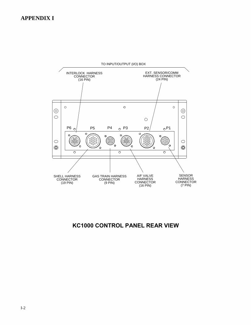
APPENDIX I
I-2
P1P2P3P4P5P6
SHELL HARNESSCONNECTOR
(19 PIN)
INTERLOCK HARNESSCONNECTOR
(16 PIN)
EXT. SENSOR/COMMHARNESS CONNECTOR
(24 PIN)
GAS TRAIN HARNESSCONNECTOR
(9 PIN)
A/F VALVEHARNESS
CONNECTOR(16 PIN)
SENSORHARNESS
CONNECTOR(7 PIN)
TO INPUT/OUTPUT (I/O) BOX
KC1000 CONTROL PANEL REAR VIEW

03/01/05 W-1 (D102.0)
STANDARD WARRANTY: Gas-Fired Water Heater
INTERNATIONAL, INC. PRESSURE VESSEL: 10 YEARS NON-PRORATED The shell shall carry a non-prorated 10 year guarantee f rom shipment against leakage due to thermal shock, water side corrosion, mechanical defects or workmanship. HEAT EXCHANGER TUBES/COMBUSTION CHAMBER: 5 YEARS The heat exchanger/combustion chamber shall carry a 5 year prorated, limited warranty from shipment against any co ndensate co rrosion, t hermal st ress failure, m echanical def ects or workmanship. O peration of t he boi ler using contaminated ai r w ill void the warranty. The heat exchangers combustion ch amber sh all not be w arranted f rom f ailure due t o scaling, liming, corrosion, or er osion due t o w ater or i nstallation co nditions. AERCO will r epair, r ebuild or exchange, at i ts option t he heat ex changer/combustion ch amber acco rding t o t he f ollowing schedule:
Year 3
Discount From Then Prevailing List Price 100%
4 70% 5 40%
“C-MORE” CONTROL PANEL: 2 YEARS FROM SHIPMENT AERCO labeled control panels are conditionally warranted against failure for (2) two years from shipment. OTHER COMPONENTS: 18 MONTHS FROM SHIPMENT All other components, with the ex ception of the ignitor and f lame detector, are conditionally guaranteed against any failure for 18 months from shipment. AERCO shall accept no responsibility if such item has been improperly installed, operated, or maintained or i f t he buy er has permitted any unauthorized modification, adjustment, and/or repairs to the item. The warranty as set forth on the back page of the Operations & Maintenance Manual is in lieu of and not in addi tion to any other express or implied warranties in any documents, or under any l aw. N o sa lesman or ot her r epresentative of AERCO has any authority to expand warranties beyond the f ace of t he sa id w arranty and pur chaser sh all not r ely on any or al statement ex cept as stated i n t he sa id w arranty. A n O fficer of A ERCO m ust do any modifications to t his warranty i n w riting. AERCO M AKES NO W ARRANTY O F MERCHANTABILITY OR F ITNESS F OR P ARTICULAR P URPOSE O R A NY O THER EXPRESS O R I MPLIED W ARRANTIES. AERCO di sclaims all r esponsibility f or any special, incidental or consequential damages. Any cl aim r elating t o t he pr oduct m ust be f iled w ith AERCO not later than 14 day s after the event-giving rise to such claim. Any claims relating to this product shall be limited to the sale price of the product at the time of sale. The sale of the product is specifically conditioned upon acceptance of these terms.

03/01/05 W-2 (D102.1)
STANDARD WARRANTY: Gas-Fired Water Heater
INTERNATIONAL, INC. CONDITIONS OF WARRANTY Should an AERCO gas-fired (natural gas or propane only) water heater or hydronic boiler fail for any of t he abov e r easons within t he sp ecified t ime per iod f rom t he dat e of or iginal shipment(s), AERCO shall at its option modify, repair or exchange the defective item. AERCO shall have the option of having the item returned, FOB its factory, or to make field replacements at t he point of i nstallation. I n no ev ent shal l AERCO be hel d liable for replacement labor charges or for freight or handling charges. AERCO shall accept no responsibility if such item has been improperly installed, operated, or maintained or i f t he buy er has permitted any unauthorized modification, adjustment, and/or repairs to the item. The use of replacement parts not manufactured or sold by AERCO will void any warranty, express or limited. In or der to pr ocess a w arranty cl aim a f ormal pur chase or der number is required prior to shipment of any warranty item. In addition, the returned item must include a Returned Goods Authorization (RGA) label, attached to the shipping carton, w hich identifies the item's return address, register number and factory authorized RGA number. Warranty coverage for all components and equipment mentioned in said warranty are not valid unless the water heater or hydronic boiler is started up by a factory certified SST (Service, Start-Up and Troubleshooting) Technician and an AERCO start-up sheet is completed. This warranty co verage i s only appl icable w ithin t he United S tates and C anada. All ot her geographical areas carry a standard warranty of 18 months from date of shipment or 12 months from startup, whichever comes first.