gf-128 - home | aercoaerco.com/sites/default/files/document/document/gf-128_omm-0079_0b...gas-fired...
TRANSCRIPT

GF-128 OMM-0079_0B
AERCO International, Inc. · 100 Oritani Dr. · Blauvelt, New York 10913 · Phone: 800-526-0288
INNOVATION Series Gas-Fired Water Heaters
USER MANUAL
Natural Gas Modulating, Condensing Water Heater Models: · INN600 · INN800 · INN1060 Applicable to Serial Numbers G-10-1350 to G-11-0563 Other documents for this product include: · GF-5030 INN Gas Supply Guide · GF-5050 INN Venting Guide · GF-5060 INN Elect. Power Guide · GF-5080 INN Sizing Guide Copies of these documents are included in Appendices J thru M of this Manual
Released: 07/21/2011
Installation, Operation, and Maintenance

GF-128 Innovation Series Water Heaters OMM-0079_0B USER MANUAL
Page 2 of 200 AERCO International, Inc. · 100 Oritani Dr. · Blauvelt, NY 10913 · Ph.: 800-526-0288 07/21/11
Disclaimer The information contained in this manual is subject to change without notice from AERCO International, Inc. AERCO makes no warranty of any kind with respect to this material, including but not limited to implied warranties of merchantability and fitness for a particular application. AERCO International is not liable for errors appearing in this manual. Nor for incidental or consequential damages occurring in connection with the furnishing, performance, or use of this material.
Technical Support: (Mon–Fri, 8am-5pm EST)
1-800-526-0288
www.aerco.com
Innovation Series Water Heaters GF-128 Table of Contents USER MANUAL OMM-0079_0B
07/21/11 AERCO International, Inc. · 100 Oritani Dr. · Blauvelt, NY 10913 · Ph: 800-526-0288 Page 3 of 200
TABLE OF CONTENTS FOREWORD ................................................................................................................... 7
CHAPTER 1. SAFETY PRECAUTIONS .................................................................. 9
1.1 WARNINGS & CAUTIONS ................................................................................................. 9
1.2 EMERGENCY SHUTDOWN ............................................................................................. 10
1.3 PROLONGED SHUTDOWN ............................................................................................. 10
CHAPTER 2. INSTALLATION ............................................................................... 13
2.1 INTRODUCTION ............................................................................................................... 13
2.2 RECEIVING THE UNIT ..................................................................................................... 13
2.3 UNPACKING .................................................................................................................... 13
2.4 SITE PREPARATION ....................................................................................................... 13 2.4.1 Installation Clearances ..............................................................................................14 2.4.2 Setting the Unit ..........................................................................................................15
2.5 WATER INLET AND OUTLET PIPING ............................................................................. 15
2.6 TEST HOSE BIB CONNECTION ...................................................................................... 16
2.7 PRESSURE & TEMPERATURE RELIEF VALVE INSTALLATION .................................. 17
2.8 SYSTEM RECIRCULATION LOOP .................................................................................. 17
2.9 CONDENSATE DRAIN & PIPING .................................................................................... 17
2.10 GAS SUPPLY PIPING .................................................................................................... 19 2.10.1 Gas Supply Specifications. ........................................................................................20 2.10.2 Manual Gas Shutoff Valve .........................................................................................20 2.10.3 External Gas Supply Regulator ..................................................................................20
2.11 AC ELECTRICAL POWER WIRING ............................................................................... 21 2.11.1 Electrical Power Requirements ..................................................................................21
2.12 FIELD CONTROL WIRING ............................................................................................. 22 2.12.1 Outdoor Air Sensor ....................................................................................................23 2.12.2 AUX SENSOR IN ......................................................................................................23 2.12.3 ANALOG IN ...............................................................................................................23 2.12.4 B.M.S. (PWM) IN .......................................................................................................24 2.12.5 SHIELD .....................................................................................................................24 2.12.6 mA OUT ....................................................................................................................24 2.12.7 EXHAUST SENSOR IN .............................................................................................24 2.12.8 INTERLOCKS............................................................................................................24 2.12.9 FAULT RELAY ..........................................................................................................25 2.12.10 AUXILIARY RELAY CONTACTS.............................................................................25
2.13 FLUE GAS VENT INSTALLATION ................................................................................. 25
2.14 COMBUSTION AIR ......................................................................................................... 25 2.14.1 Combustion From Outside the Building .....................................................................26 2.14.2 Combustion Air from Inside the Building ....................................................................26

GF-128 Innovation Series Water Heaters OMM-0079_0B USER MANUAL Table of Contents
Page 4 of 200 AERCO International, Inc. · 100 Oritani Dr. · Blauvelt, NY 10913 · Ph.: 800-526-0288 07/21/11
2.15 SEALED COMBUSTION ................................................................................................. 26
CHAPTER 3. OPERATION .................................................................................... 27
3.1 INTRODUCTION ............................................................................................................... 27
3.2 CONTROL PANEL DESCRIPTION .................................................................................. 27
3.3 CONTROL PANEL MENUS .............................................................................................. 31 3.3.1 Menu Processing Procedure ......................................................................................31
3.4 OPERATING MENU ......................................................................................................... 32
3.5 SETUP MENU ................................................................................................................... 33
3.6 CONFIGURATION MENU ................................................................................................. 34
3.7 TUNING MENU ................................................................................................................. 35
3.8 START SEQUENCE ......................................................................................................... 36
3.9 START/STOP LEVELS ..................................................................................................... 38
CHAPTER 4. INITIAL START-UP ......................................................................... 41
4.1 INITIAL START-UP REQUIREMENTS ............................................................................. 41
4.2 TOOLS AND INSTRUMENTATION FOR COMBUSTION CALIBRATION ....................... 41 4.2.1 Required Tools & Instrumentation..............................................................................41 4.2.2 Installing Gas Supply Manometer ..............................................................................42 4.2.3 Accessing the Analyzer Probe Port ............................................................................42
4.3 NATURAL GAS COMBUSTION CALIBRATION .............................................................. 43
4.4 REASSEMBLY ................................................................................................................. 45
4.5 TEMPERATURE CONTROL CALIBRATION ................................................................... 45 4.5.1 Setting the Outlet Water Temperature Setpoint .........................................................45 4.5.2 Minimum Load Adjustment ........................................................................................46 4.5.3 Maximum Load Adjustment .......................................................................................46
4.6 OVER-TEMPERATURE LIMIT SWITCHES ...................................................................... 47
CHAPTER 5. SAFETY DEVICE TESTING ............................................................ 49
5.1 TESTING OF SAFETY DEVICES ..................................................................................... 49
5.2 LOW GAS PRESSURE FAULT TEST .............................................................................. 49
5.3 HIGH GAS PRESSURE TEST .......................................................................................... 50
5.4 LOW WATER LEVEL FAULT TEST ................................................................................. 50
5.5 WATER TEMPERATURE FAULT TEST .......................................................................... 51
5.6 INTERLOCK TESTS ......................................................................................................... 52 5.6.1 Remote Interlock .......................................................................................................52 5.6.2 Delayed Interlock .......................................................................................................53
5.7 FLAME FAULT TESTS ..................................................................................................... 53
5.8 AIR FLOW FAULT TESTS ............................................................................................... 54

Innovation Series Water Heaters GF-128 Table of Contents USER MANUAL OMM-0079_0B
07/21/11 AERCO International, Inc. · 100 Oritani Dr. · Blauvelt, NY 10913 · Ph: 800-526-0288 Page 5 of 200
5.9 SSOV PROOF OF CLOSURE SWITCH ........................................................................... 56
5.10 PURGE SWITCH OPEN DURING PURGE ..................................................................... 56
5.11 IGNITION SWITCH OPEN DURING IGNITION ............................................................... 57
5.12 SAFETY PRESSURE RELIEF VALVE TEST .................................................................. 58
CHAPTER 6. MAINTENANCE .............................................................................. 59
6.1 MAINTENANCE SCHEDULE ........................................................................................... 59
6.2 IGNITER-INJECTOR ........................................................................................................ 60
6.3 FLAME DETECTOR ......................................................................................................... 61
6.4 COMBUSTION CALIBRATION ........................................................................................ 62
6.5 SAFETY DEVICE TESTING ............................................................................................. 62
6.6 FIRESIDE INSPECTION ................................................................................................... 62
6.7 WATERSIDE INSPECTION .............................................................................................. 65
6.8 HEAT EXCHANGER CLEANING ..................................................................................... 67 6.8.1 Pumping System Set-Up Instructions ........................................................................67 6.8.2 Cleaning Procedure ...................................................................................................68 6.8.3 Testing HydroSkrub Effectiveness .............................................................................69
6.9 CONDENSATE DRAIN TRAP .......................................................................................... 69
6.10 AIR FILTER REPLACEMENT .......................................................................................... 70
6.11 SHUTTING THE WATER HEATER DOWN FOR AN EXTENDED PERIOD OF TIME ...... 71
6.12 PLACING THE HEATER BACK IN SERVICE AFTER A PROLONGED SHUTDOWN .... 71
CHAPTER 7. TROUBLESHOOTING GUIDE ........................................................ 73
7.1 INTRODUCTION ............................................................................................................... 73
7.2 ADDITIONAL FAULTS WITHOUT SPECIFIC FAULT MESSAGES ................................. 84
CHAPTER 8. RS232 COMMUNICATION .............................................................. 87
8.1 INTRODUCTION ............................................................................................................... 87
8.2 RS232 COMMUNICATION SETUP .................................................................................. 87
8.3 MENU PROCESSING UTILIZING RS232 COMMUNICATION ......................................... 87
8.4 DATA LOGGING .............................................................................................................. 88 8.4.1 Fault Log ...................................................................................................................88 8.4.2 Operation Time Log ...................................................................................................89 8.4.3 Sensor Log ................................................................................................................89
GF-128 Innovation Series Water Heaters OMM-0079_0B USER MANUAL Table of Contents
Page 6 of 200 AERCO International, Inc. · 100 Oritani Dr. · Blauvelt, NY 10913 · Ph.: 800-526-0288 07/21/11
APPENDIX A: WATER HEATER MENU ITEM DESCRIPTIONS ............................... 91
APPENDIX B: STARTUP, STATUS AND FAULT MESSAGES ................................. 95
APPENDIX C 99TEMPERATURE SENSOR RESISTANCE/VOLTAGE CHART ........ 99
APPENDIX D: WATER HEATER DEFAULT SETTINGS .......................................... 101
APPENDIX E: PARTS LIST DRAWINGS .................................................................. 103
APPENDIX F: PIPING DRAWINGS ........................................................................... 113
APPENDIX G: C-MORE CONTROL PANEL VIEWS ................................................ 127
APPENDIX H: C-MORE WIRING DIAGRAMS .......................................................... 129
APPENDIX I: RECOMMENDED SPARES ................................................................ 137
APPENDIX J: GF-5030: GAS COMPONENTS & SUPPLY DESIGN GUIDE .......... 139
APPENDIX K: GF-5050: VENTING & COMBUSTION AIR GUIDE ......................... 151
APPENDIX L: GF-5060: ELECTRICAL POWER GUIDE ......................................... 175
APPENDIX M: GF-5080: COMMERCIAL LAUNDRY SIZING GUIDE ..................... 183
APPENDIX N: LIMITED WARRANTY ....................................................................... 195
Innovation Series Water Heaters GF-128 Foreword USER MANUAL OMM-0079_0B
07/21/11 AERCO International, Inc. · 100 Oritani Dr. · Blauvelt, NY 10913 · Ph: 800-526-0288 Page 7 of 200
FOREWORD The AERCO Innovation Series Water Heaters are modulating units which represent a true industry advance that meets the needs of today's energy efficiency and environmental concerns. Designed for use in any domestic water heating system, each Innovation model provides precisely-controlled potable water within ±2°F of setpoint, regardless of flow rate. Innovation’s compact size and varied venting capabilities allow maximum installation flexibility. The Innovation Series Heaters, with their load tracking controls modulate over a 20:1 turn down ratio to match the system demand and yield high thermal efficiencies. When installed and operated on natural gas in accordance with this Instruction Manual, the Innovation Series Models covered herein comply with the NOx emission standards outlined in:
· South Coast Air Quality Management District (SCAQMD), Rule 1146.2 · Texas Commission on Environmental Quality (TCEQ), Title 30, Chapter 117,
Rule 117.465
Whether used in singular or modular arrangements, the Innovation Heaters offer the maximum flexibility in venting with minimum installation space requirements. Innovation’s advanced electronic controls offer simplified integration with today’s Energy Management Systems. For service or parts, contact your local sales representative or AERCO INTERNATIONAL. NAME: ORGANIZATION:
ADDRESS: TELEPHONE: INSTALLATION DATE: ___________________________________________________

GF-128 Innovation Series Water Heaters OMM-0079_0B USER MANUAL Foreword
Page 8 of 200 AERCO International, Inc. · 100 Oritani Dr. · Blauvelt, NY 10913 · Ph.: 800-526-0288 07/21/11
This Page Is Intentionally Blank
Chapter 1 Innovation Series Water Heaters GF-128 Safety Precautions USER MANUAL OMM-0079_0B
07/21/11 AERCO International, Inc. · 100 Oritani Dr. · Blauvelt, NY 10913 · Ph: 800-526-0288 Page 9 of 200
CHAPTER 1. SAFETY PRECAUTIONS 1.1 WARNINGS & CAUTIONS Installers and operating personnel MUST, at all times, observe all safety regulations. The following warnings and cautions are general and must be given the same attention as specific precautions included in these instructions. In addition to all the requirements included in this AERCO Instruction Manual, the installation of units MUST conform with local building codes, or, in the absence of local codes, ANSI Z223.1 (National Fuel Gas Code Publication No. NFPA-54) for gas-fired heaters and ANSI/NFPASB for LP gas-fired heaters. Where applicable, the equipment shall be installed in accordance with the current Installation Code for Gas Burning Appliances and Equipment, CSA B149.1, and applicable Provincial regulations for the class; which should be carefully followed in all cases. Authorities having jurisdiction should be consulted before installations are made.
See pages 11 and 12 for important information regarding installation of units within the Commonwealth of Massachusetts.
IMPORTANT This Instruction Manual is an integral part of the product and must be maintained in legible condition. It must be given to the user by the installer and kept in a safe place for future reference.
IMPORTANT Read the following restrictions prior to installing the water heater: 1. The water heater can only be used for applications where the chlorine concentrations Do Not Exceed 4 mg/L which is the Environmental Protection Agency limit for chlorine concentrations in drinking water. 2. Do Not use this heater for a pool heating application.
WARNING DO NOT USE MATCHES, CANDLES, FLAMES, OR OTHER SOURCES OF IGNITION TO CHECK FOR GAS LEAKS.
WARNING FLUIDS UNDER PRESSURE MAY CAUSE INJURY TO PERSONNEL OR DAMAGE TO EQUIPMENT WHEN RELEASED. BE SURE TO SHUT OFF ALL INCOMING AND OUTGOING WATER SHUTOFF VALVES. CAREFULLY DECREASE ALL TRAPPED PRESSURES TO ZERO BEFORE PERFORMING MAINTENANCE.
WARNING ELECTRICAL VOLTAGES UP TO 120 VAC MAY BE USED IN THIS EQUIPMENT. THEREFORE THE COVER ON THE UNIT’S POWER BOX (LOCATED BEHIND THE FRONT PANEL DOOR) MUST BE INSTALLED AT ALL TIMES, EXCEPT DURING MAINTENANCE AND SERVICING.
WARNING A DOUBLE-POLE SWITCH MUST BE INSTALLED ON THE ELECTRICAL SUPPLY LINE OF THE UNIT. THE SWITCH MUST BE INSTALLED IN AN EASILY ACCESSIBLE POSITION TO QUICKLY AND SAFELY DISCONNECT ELECTRICAL SERVICE. DO NOT AFFIX SWITCH TO UNIT SHEET METAL ENCLOSURES.
GF-128 Innovation Series Water Heaters Chapter 1 OMM-0079_0B USER MANUAL Safety Precautions
Page 10 of 200 AERCO International, Inc. · 100 Oritani Dr. · Blauvelt, NY 10913 · Ph.: 800-526-0288 07/21/11
CAUTIONS Must be observed to prevent equipment damage or loss of operating effectiveness.
CAUTION Many soaps used for gas pipe leak testing are corrosive to metals. The piping must be rinsed thoroughly with clean water after leak checks have been completed.
CAUTION DO NOT use this heater if any part has been under water. Call a qualified service technician to inspect and replace any part that has been under water.
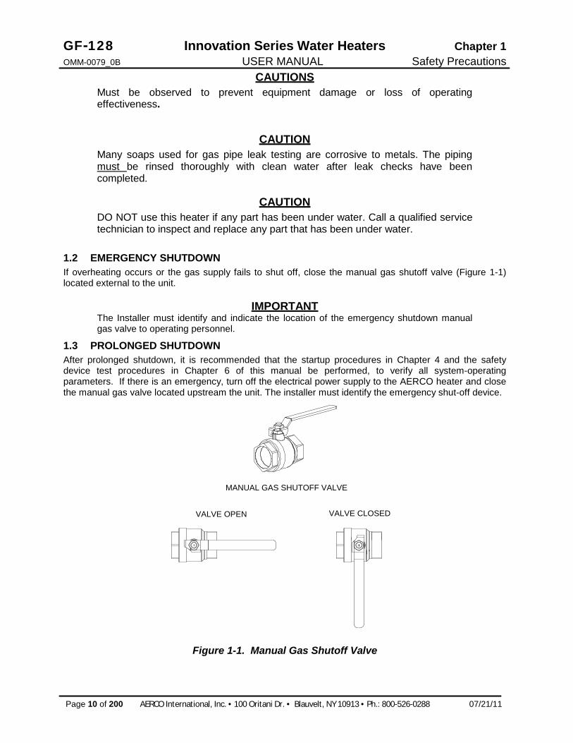
1.2 EMERGENCY SHUTDOWN If overheating occurs or the gas supply fails to shut off, close the manual gas shutoff valve (Figure 1-1) located external to the unit.
IMPORTANT The Installer must identify and indicate the location of the emergency shutdown manual gas valve to operating personnel.
1.3 PROLONGED SHUTDOWN After prolonged shutdown, it is recommended that the startup procedures in Chapter 4 and the safety device test procedures in Chapter 6 of this manual be performed, to verify all system-operating parameters. If there is an emergency, turn off the electrical power supply to the AERCO heater and close the manual gas valve located upstream the unit. The installer must identify the emergency shut-off device.
MANUAL GAS SHUTOFF VALVE
VALVE OPEN VALVE CLOSED
Figure 1-1. Manual Gas Shutoff Valve

Chapter 1 Innovation Series Water Heaters GF-128 Safety Precautions USER MANUAL OMM-0079_0B
07/21/11 AERCO International, Inc. · 100 Oritani Dr. · Blauvelt, NY 10913 · Ph: 800-526-0288 Page 11 of 200
IMPORTANT – FOR MASSACHUSETTS INSTALLATIONS Water heater Installations within the Commonwealth of Massachusetts must conform to the following requirements: · Heater must be installed by a plumber or a gas fitter who is licensed within the
Commonwealth of Massachusetts. · Prior to unit operation, the complete gas train and all connections must be leak
tested using a non-corrosive soap. · The vent termination must be located a minimum of 4 feet above grade level.
If side-wall venting is used, the installation must conform to the following requirements extracted from 248 CMR 5.08 (2):
(a) For all side wall horizontally vented gas fueled equipment installed in every dwelling, building or structure used in whole or in part for residential purposes, including those owned or operated by the Commonwealth and where the side wall exhaust vent termination is less than seven (7) feet above finished grade in the area of the venting, including but not limited to decks and porches, the following requirements shall be satisfied:
1. INSTALLATION OF CARBON MONOXIDE DETECTORS. At the time of installation of the side wall horizontal vented gas fueled equipment, the installing plumber or gasfitter shall observe that a hard wired carbon monoxide detector with an alarm and battery back-up is installed on the floor level where the gas equipment is to be installed. In addition, the installing plumber or gasfitter shall observe that a battery operated or hard wired carbon monoxide detector with an alarm is installed on each additional level of the dwelling, building or structure served by the side wall horizontal vented gas fueled equipment. It shall be the responsibility of the property owner to secure the services of qualified licensed professionals for the installation of hard wired carbon monoxide detectors.
a. In the event that the side wall horizontally vented gas fueled equipment is installed in a crawl space or an attic, the hard wired carbon monoxide detector with alarm and battery back-up may be installed on the next adjacent floor level.
b. In the event that the requirements of this subdivision can not be met at the time of completion of installation, the owner shall have a period of thirty (30) days to comply with the above requirements; provided, however, that during said thirty (30) day period, a battery operated carbon monoxide detector with an alarm shall be installed.
2. APPROVED CARBON MONOXIDE DETECTORS. Each carbon monoxide detector as required in accordance with the above provisions shall comply with NFPA 720 and be ANSI/UL 2034 listed and IAS certified.
3. SIGNAGE. A metal or plastic identification plate shall be permanently mounted to the exterior of the building at a minimum height of eight (8) feet above grade directly in line with the exhaust vent terminal for the horizontally vented gas fueled heating appliance or equipment. The sign shall read, in print size no less than one-half (1/2) inch in size, "GAS VENT DIRECTLY BELOW. KEEP CLEAR OF ALL OBSTRUCTIONS".
4. INSPECTION. The state or local gas inspector of the side wall horizontally vented gas fueled equipment shall not approve the installation unless, upon inspection, the inspector observes carbon monoxide detectors and signage installed in accordance with the provisions of 248 CMR 5.08(2)(a)1 through 4.

GF-128 Innovation Series Water Heaters Chapter 1 OMM-0079_0B USER MANUAL Safety Precautions
Page 12 of 200 AERCO International, Inc. · 100 Oritani Dr. · Blauvelt, NY 10913 · Ph.: 800-526-0288 07/21/11
(b) EXEMPTIONS: The following equipment is exempt from 248 CMR 5.08(2)(a)1 through 4:
1. The equipment listed in Chapter 10 entitled "Equipment Not Required To Be Vented" in the most current edition of NFPA 54 as adopted by the Board; and
2. Product Approved side wall horizontally vented gas fueled equipment installed in a room or structure separate from the dwelling, building or structure used in whole or in part for residential purposes.
(c) MANUFACTURER REQUIREMENTS - GAS EQUIPMENT VENTING SYSTEM PROVIDED. When the manufacturer of Product Approved side wall horizontally vented gas equipment provides a venting system design or venting system components with the equipment, the instructions provided by the manufacturer for installation of the equipment and the venting system shall include:
1. Detailed instructions for the installation of the venting system design or the venting system components; and
2. A complete parts list for the venting system design or venting system.
(d) MANUFACTURER REQUIREMENTS - GAS EQUIPMENT VENTING SYSTEM NOT PROVIDED. When the manufacturer of a Product Approved side wall horizontally vented gas fueled equipment does not provide the parts for venting the flue gases, but identifies "special venting systems", the following requirements shall be satisfied by the manufacturer:
1. The referenced "special venting system" instructions shall be included with the appliance or equipment installation instructions; and
2. The "special venting systems" shall be Product Approved by the Board, and the instructions for that system shall include a parts list and detailed installation instructions.
(e) A copy of all installation instructions for all Product Approved side wall horizontally vented gas fueled equipment, all venting instructions, all parts lists for venting instructions, and/or all venting design instructions shall remain with the appliance or equipment at the completion of the installation. ______________________________________ [End of Extracted Information From 248 CMR 5.08 (2)]

Chapter 2 Innovation Series Water Heaters GF-128 Installation USER MANUAL OMM-0079_0B
07/21/11 AERCO International, Inc. · 100 Oritani Dr. · Blauvelt, NY 10913 · Ph: 800-526-0288 Page 13 of 200
CHAPTER 2. INSTALLATION 2.1 INTRODUCTION This Chapter provides the descriptions and procedures necessary to unpack, inspect and install AERCO Innovation Water Heater Models INN 600, INN 800 and INN 1060.
2.2 RECEIVING THE UNIT Each Innovation Water Heating System is shipped as a single crated unit. The shipping weight is approximately 1200 pounds. The unit must be moved with the proper rigging equipment for safety and to avoid equipment damage. The unit should be completely inspected for evidence of shipping damage and shipment completeness at the time of receipt from the carrier and before the bill of lading is signed.
NOTE AERCO is not responsible for lost or damaged freight. Each unit has a Tip-N-Tell indicator on the outside of the crate. This indicates if the unit has been turned on its side during shipment. If the Tip-N-Tell indicator is tripped, do not sign for the shipment. Note the information on the carrier’s paperwork and request a freight claim and inspection by a claims adjuster before proceeding. Any other visual damage to the packaging materials should also be made clear to the delivering carrier.
2.3 UNPACKING Carefully unpack the unit taking care not to damage the unit enclosure when cutting away packaging materials
After unpacking, a close inspection of the unit should be made to ensure that there is no evidence of damage not indicated by the Tip-N-Tell indicator. The freight carrier should be notified immediately if any damage is detected.
The following accessories come standard with each unit and are either packed separately within the unit’s shipping container or are factory installed on the unit:
· Pressure/Temperature Gauge · Spare Spark Igniter-Injector · Spare Flame Detector · ASME Pressure Relief Valve · Condensate Drain Trap · 1-1/2” Gas Supply Shutoff Valve When optional accessories are ordered, they may be packed within the unit’s shipping container, factory installed on the unit, or packed and shipped in a separate container. Any standard or optional accessories shipped loose should be identified and stored in a safe place until ready for installation or use.
2.4 SITE PREPARATION Ensure that the site selected for installation of the Innovation Water Heater includes:
· Access to AC Input Power at 120 VAC, Single-Phase, 60 Hz @ 20 Amps. · Access to Natural Gas line at a minimum pressure of 4 inches W.C.

GF-128 Innovation Series Water Heaters Chapter 2 OMM-0079_0B USER MANUAL Installation
Page 14 of 200 AERCO International, Inc. · 100 Oritani Dr. · Blauvelt, NY 10913 · Ph.: 800-526-0288 07/21/11
2.4.1 Installation Clearances Innovation Models 790 and 1060 are packaged in enclosures having identical exterior dimensions. The unit must be installed with the prescribed clearances for service as shown in Figure 2-1. The minimum clearance dimensions, required by AERCO, are listed below. However, if Local Building Codes require additional clearances, these codes shall supersede AERCO’s requirements. Minimum acceptable clearances required are as follows:
· Sides: 24 inches · Front : 24 inches · Rear: 30 inches · Top: 18 inches All gas piping, water piping and electrical conduit or cable must be arranged so that they do not interfere with the removal of any panels, or inhibit service or maintenance of the unit.
Figure 2-1 Innovation Water Heater Clearances
WARNING KEEP THE UNIT AREA CLEAR AND FREE FROM ALL COMBUSTIBLE MATERIALS AND FLAMMABLE VAPORS OR LIQUIDS.
CAUTION While packaged in the shipping container, the unit must be moved by pallet jack or forklift from the FRONT ONLY.
FOR MASSACHUSSETTS ONLY: For Massachusetts installations, the unit must be installed by a plumber or gas-fitter who is licensed within the Commonwealth of Massachusetts. In addition, the installation must comply with all requirements specified in Chapter 1 (Safety Precautions), pages 11 and 12.

Chapter 2 Innovation Series Water Heaters GF-128 Installation USER MANUAL OMM-0079_0B
07/21/11 AERCO International, Inc. · 100 Oritani Dr. · Blauvelt, NY 10913 · Ph: 800-526-0288 Page 15 of 200
2.4.2 Setting the Unit The unit must be installed on a 4 inch to 6 inch housekeeping pad to ensure proper condensate drainage. If anchoring the unit, refer to the dimensional drawings in Appendix F for anchor locations. Two lifting lugs are provided at the top of the heat exchanger as shown in Figure 2-2. USE THESE TWO LUGS TO LIFT AND MOVE THE UNIT. Remove the top panel from the unit to provide access to the lifting lugs. Remove the four (4) lag screws securing the unit to the shipping skid. Lift the unit off the shipping skid and position it on the 4 inch to 6 inch housekeeping concrete pad (required) in the desired location.
Figure 2-2
Partial Top View Showing Lifting Tab Location
In multiple unit installations, it is important to plan the position of each unit in advance. Sufficient space for piping connections and future service/maintenance requirements must also be taken into consideration. All piping must include ample provisions for expansion.
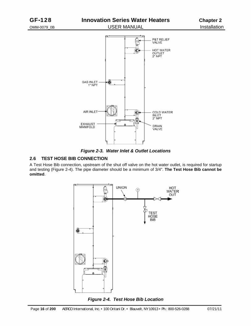
2.5 WATER INLET AND OUTLET PIPING The locations of the 2" NPT cold water inlet and hot water outlet piping connections are shown in Figure 2-3. Flow rates through the unit are limited to 30 gpm continuous and 40 gpm intermittent.
Shut-off valves and union connections must be installed in the inlet and outlet lines for maintenance. The use of dielectric unions is recommended.
NOTE: All piping must be arranged so that it does not interfere with removal of any covers, inhibit service or maintenance, or prevent access between the unit and walls, or another unit.
GF-128 Innovation Series Water Heaters Chapter 2 OMM-0079_0B USER MANUAL Installation
Page 16 of 200 AERCO International, Inc. · 100 Oritani Dr. · Blauvelt, NY 10913 · Ph.: 800-526-0288 07/21/11
Figure 2-3. Water Inlet & Outlet Locations 2.6 TEST HOSE BIB CONNECTION A Test Hose Bib connection, upstream of the shut off valve on the hot water outlet, is required for startup and testing (Figure 2-4). The pipe diameter should be a minimum of 3/4". The Test Hose Bib cannot be omitted.
Figure 2-4. Test Hose Bib Location

Chapter 2 Innovation Series Water Heaters GF-128 Installation USER MANUAL OMM-0079_0B
07/21/11 AERCO International, Inc. · 100 Oritani Dr. · Blauvelt, NY 10913 · Ph: 800-526-0288 Page 17 of 200
NOTE: The maximum working pressure for installations within the Province of Alberta is 87 psig. Therefore, a pressure & temperature relief valve with a setting of 75 psig/210°F is supplied with Alberta shipments. See Drawing AP-A-863 in Appendix E.
2.7 PRESSURE & TEMPERATURE RELIEF VALVE INSTALLATION An ASME rated Pressure & Temperature (P&T) Relief Valve is supplied with each Innovation Water Heater. With the exception of Alberta installations (see above Note), the valve setpoint is 150 psig/210°F. The P&T Relief Valve is installed at the top of the Recirculation Loop Assembly as shown in Figure 2-5. A suitable pipe joint compound should be used on the threaded connections. Any excess should be wiped off to avoid getting any into the valve body. The relief valve should be piped to within 12 inches of the floor to prevent injury in the event of a discharge. The relief piping must be full size, 1-1/2”, without reduction. No valves, restrictions, or other blockages are allowed in the discharge line. In multiple unit installations the discharge lines must not be manifolded together. Each must be individually run to a suitable discharge location.
Figure 2-5. P&T Relief Valve Location
2.8 SYSTEM RECIRCULATION LOOP The System Recirculation Loop Assembly is located at the rear of the unit as shown in Figure 2-5. This assembly contains a recirculator pump which connects between the upper hot water outlet and lower cold water inlet of the unit’s heat exchanger. The purpose of this loop is to provide feed-forward (FFWD) temperature control by mixing a portion of the hot water outlet with the cold water inlet of the unit. Temperature sensors located in the hot water outlet and cold water inlet provide temperature data to the C-More Control System. The Control System utilizes this data to modulate the fire rate (Air/Fuel Valve position) to precisely maintain the hot water outlet temperature at the selected setpoint temperature.
2.9 CONDENSATE DRAIN & PIPING The Innovation Water Heater is designed to condense water vapor from the flue products. Therefore, the installation must have provisions for suitable condensate drainage or collection.
The condensate drain port, is located on the exhaust manifold at the rear of the unit (Figure 2-6). This drain port must be connected to the Condensate Trap (part no. 24060) which is packed separately within the unit’s shipping container. The Condensate Trap inlet and outlet connections contain tapped 3/4” NPT ports.

GF-128 Innovation Series Water Heaters Chapter 2 OMM-0079_0B USER MANUAL Installation
Page 18 of 200 AERCO International, Inc. · 100 Oritani Dr. · Blauvelt, NY 10913 · Ph.: 800-526-0288 07/21/11
Figure 2-6. Condensate Drain Connection Location A sample Condensate Trap installation is shown in Figure 2-7. However, the actual installation details for the trap will vary depending on the available clearances, housekeeping pad height/ dimensions and other prevailing conditions at the site. the following general guidelines must be observed to ensure proper condensate drainage:
· The condensate trap inlet (Figure 2-6) must be level with, or lower than the exhaust manifold drain port.
· The base of the condensate trap must be supported to ensure that it is level (horizontal). · The trap must be removable for routine maintenance. AERCO recommends that a union be utilized
between the exhaust manifold condensate drain port and the trap inlet port. While observing the above guidelines, install the condensate trap as follows,
1. Connect the condensate trap inlet to the exhaust manifold drain connection using the appropriate piping components (nipples, reducers, elbows, etc.) for the heater installation site.
2. At the condensate trap outlet, install a 3/4” NPT nipple.
3. Connect a length of 1” I.D polypropylene hose to the trap outlet and secure with a hose clamp.
4. Route the hose on the trap outlet to a nearby floor drain. If a floor drain is not available, a condensate pump can be used to remove the condensate to drain. The maximum condensate flow rate is 20 GPH. The condensate drain trap, associated fittings and drain line must be removable for routine maintenance.

Chapter 2 Innovation Series Water Heaters GF-128 Installation USER MANUAL OMM-0079_0B
07/21/11 AERCO International, Inc. · 100 Oritani Dr. · Blauvelt, NY 10913 · Ph: 800-526-0288 Page 19 of 200
Figure 2-7. Sample Condensate Trap Installation 2.10 GAS SUPPLY PIPING The AERCO Innovation Gas Components and Supply Design Guide, GF-5030 (see Appendix J) must be consulted prior to designing or installing any gas supply piping.
WARNING NEVER USE MATCHES, CANDLES, FLAMES OR OTHER SOURCES OF IGNITION TO CHECK FOR GAS LEAKS.
CAUTION Many soaps used for gas pipe leak testing are corrosive to metals. Therefore, piping must be rinsed thoroughly with clean water after leak checks have been completed.
NOTE All gas piping must be arranged so that it does not interfere with removal of any covers, inhibit service/maintenance, or restrict access between the unit and walls, or another unit.
Innovation units contain a 1 inch NPT gas inlet connection on the rear of the unit as shown in Figure 2-3.
Prior to installation, all pipes should be de-burred and internally cleared of any scale, metal chips or other foreign particles. Do Not install any flexible connectors or unapproved gas fittings. Piping must be supported from the floor, ceiling or walls only and must not be supported by the unit.
A suitable piping compound, approved for use with natural gas, should be used. Any excess must be wiped off to prevent clogging of components.
To avoid unit damage when pressure testing gas piping, isolate the unit from the gas supply piping. At no time should the gas pressure applied to the unit exceed 14” W.C.. Leak test all external piping thoroughly using a soap and water solution or suitable equivalent. The gas piping used must meet all applicable codes.

GF-128 Innovation Series Water Heaters Chapter 2 OMM-0079_0B USER MANUAL Installation
Page 20 of 200 AERCO International, Inc. · 100 Oritani Dr. · Blauvelt, NY 10913 · Ph.: 800-526-0288 07/21/11
2.10.1 Gas Supply Specifications. The gas supply input specifications to the unit for Natural Gas are as follows:
The maximum static pressure to the unit must not exceed 14” W.C. The gas supply pressure to the unit must be of sufficient capacity to provide 1060 cfh while maintaining the gas pressure at 7 inches W.C. for FM gas trains.
2.10.2 Manual Gas Shutoff Valve A manual shut-off valve must be installed in the gas supply line upstream of the Heater as shown in Figure 2-8. Maximum allowable gas pressure to the Heater is 14” W.C.
NOTE Paragraph 2.10.3 applies only to water heater installations within the Commonwealth of Massachusetts.
2.10.3 External Gas Supply Regulator For Massachusetts installations, a mandatory external gas supply regulator must be positioned as shown in Figure 2-6. The gas supply regulator must be properly vented to outdoors. Consult the local gas utility for detailed requirements concerning venting of the the supply gas regulator.
NOTE The external regulator must be capable of regulating 40,000 – 1,060,000 BTU/HR of natural gas while maintaining a gas pressure of 7.0” W.C. to the unit.
CAUTION A lock-up style regulator MUST be used when gas supply pressure will exceed 14” W.C.
Figure 2-8. Manual Gas Shut-Off Valve Location

Chapter 2 Innovation Series Water Heaters GF-128 Installation USER MANUAL OMM-0079_0B
07/21/11 AERCO International, Inc. · 100 Oritani Dr. · Blauvelt, NY 10913 · Ph: 800-526-0288 Page 21 of 200
2.11 AC ELECTRICAL POWER WIRING The AERCO Innovation Electrical Power Wiring Guide, GF-5060 (see Appendix L), must be consulted prior to connecting any AC power wiring to the unit. External AC power connections are made to the unit inside the Power Box on the front panel of the unit. Remove the front door of the unit to access the Power Box mounted directly above the Control Box. Loosen the four Power Box cover screws and remove cover to access the AC terminal connections inside the Power Box (Figure 2-9).
Figure 2-9. Power Box With Cover Removed
NOTE All electrical conduit and hardware must be installed so that it does not interfere with the removal of any unit covers, inhibit service/maintenance, or prevent access between the unit and walls or another unit.
2.11.1 Electrical Power Requirements The AERCO Innovation Heater accepts 120 VAC, single-phase, 60 Hz @ 20A. The Power Box contains a terminal block as shown in Figure 2-8. In addition, a wiring diagram showing the required AC power connections is provided on the front cover of the Power Box.
Each unit must be connected to a dedicated electrical circuit. NO OTHER DEVICES SHOULD BE ON THE SAME ELECTRICAL CIRCUIT AS THE HEATER.
A double-pole switch must be installed on the electrical supply line in an easily accessible location to quickly and safely disconnect electrical service. DO NOT attach the switch to sheet metal enclosures of the unit.
After placing the unit in service, the ignition safety shutoff device must be tested. If an external electrical power source is used, the installed boiler must be electrically bonded to ground in accordance with the requirements of the authority having jurisdiction. In the absence of such requirements, the installation shall conform to National Electrical Code (NEC), ANSI/NFPA 70 and/or the Canadian Electrical Code (CEC) Part I, CSA C22.1 Electrical Code.
For electrical power wiring diagrams, see the AERCO Innovation Electrical Power Wiring Guide, (GF-5060).

GF-128 Innovation Series Water Heaters Chapter 2 OMM-0079_0B USER MANUAL Installation
Page 22 of 200 AERCO International, Inc. · 100 Oritani Dr. · Blauvelt, NY 10913 · Ph.: 800-526-0288 07/21/11
Figure 2-10. AC Terminal Block Configurations
2.12 FIELD CONTROL WIRING Each unit is fully wired from the factory with an internal operating control system. No field control wiring is required for normal operation. However, the C-More control system used with all Innovation Heaters does allow for some control and monitoring features. Wiring connections for these features are made in the Input/Output (I/O) Box. The I/O Box is located on the upper-left portion of the unit front panel (Figure 2-11) behind the removable front panel door. To access the I/O Box terminal strips shown in Figure 2-11, loosen the four cover screws and remove the cover. All field wiring is installed from the rear of the panel by routing the wires through one of the four bushings provided.
Refer to the wiring diagram provided on the cover of the I/O Box (Figure 2-12) when making all wiring connections.
Figure 2-11. Input/Output (I/O) Box Location Since identical I/O Boxes are used with both AERCO gas-fired boilers and water heaters, some of the input and output connections apply only to boilers while others are common to both boilers and heaters. These I/O Box connections are noted in the following paragraphs.

Chapter 2 Innovation Series Water Heaters GF-128 Installation USER MANUAL OMM-0079_0B
07/21/11 AERCO International, Inc. · 100 Oritani Dr. · Blauvelt, NY 10913 · Ph: 800-526-0288 Page 23 of 200
CAUTION DO NOT make any connections to the I/O Box terminals labeled “NOT USED”. Attempting to do so may cause equipment damage.
Figure 2-12. I/O Box Terminal Strips
2.12.1 Outdoor Air Sensor Not Applicable to Water Heaters.
2.12.2 AUX SENSOR IN The AUX SENSOR IN terminals can be used to add an additional temperature sensor for monitoring purposes. This input is always enabled and is a view only input that can be seen in the operating menu. The sensor must be wired to the AUX SENSOR IN and SENSOR COMMON and must be similar to AERCO BALCO wire sensor P/N 12449. A resistance chart for this sensor is located in APPENDIX C.
2.12.3 ANALOG IN The ANALOG IN + and – terminals are used when an external signal is used to change the setpoint (Remote Setpoint Mode) of the heater.
Either a 4 to 20 mA /1 to 5 VDC or a 0 to 20 mA/ 0 to 5 VDC signal may be used to vary the setpoint or air/fuel valve position. The factory default setting is for 4 to 20 mA / 1 to 5 VDC, however this may be changed to 0 to 20 mA / 0 to 5 VDC using the Configuration Menu described in Chapter 3.
If voltage rather than current is selected as the drive signal, a DIP switch must be set on the PMC Board located inside the Control Box. Contact the AERCO factory for information on setting DIP switches.

GF-128 Innovation Series Water Heaters Chapter 2 OMM-0079_0B USER MANUAL Installation
Page 24 of 200 AERCO International, Inc. · 100 Oritani Dr. · Blauvelt, NY 10913 · Ph.: 800-526-0288 07/21/11
All supplied signals must be floating (unground-ed) signals. Connections between the source and the Heater’s I/O Box must be made using twisted shielded pair of 18–22 AWG wire such as Belden 9841(see Figure 2-12). Polarity must be maintained and the shield must be connected only at the source end and must be left floating (not connected) at the Heater’s I/O Box.
Whether using voltage or current for the drive signal, they are linearly mapped to a 40°F to 240°F setpoint or a 0% to 100% air/fuel valve position. No scaling for these signals is provided
2.12.4 B.M.S. (PWM) IN Not Applicable to Water Heaters
2.12.5 SHIELD The SHIELD terminals are used to terminate any shields used on sensor wires connected to the unit. Shields must only be connected to these terminals.
2.12.6 mA OUT These terminals provide a 4 to 20 mA output that can be used to monitor setpoint ( 40°F to 240°F), outlet temperature (30°F to 240°F), or air/fuel valve position (0% to 100% open). This function is enabled in the Configuration Menu (Chapter 3, Table 3-4).
2.12.7 EXHAUST SENSOR IN These terminals permit an exhaust sensor to be connected to the exhaust manifold of the heater.
2.12.8 INTERLOCKS The unit offers two interlock circuits for interfacing with Energy Management Systems and auxiliary equipment such as pumps or louvers or other accessories. These interlocks are called the Remote Interlock and Delayed Interlock (Figure 2-12). The wiring terminals for these interlocks are located inside the I/O Box on the left side of the unit. The I/O Box cover contains a wiring diagram which shows the terminal strip locations for these interlocks (REMOTE INTL’K IN and DELAYED INTL’K IN). Both interlocks, described below, are factory wired in the closed position.
NOTE:
Both the Delayed Interlock and Remote Interlock must be in the closed position for the unit to fire.
2.12.8.1 REMOTE INTERLOCK IN The remote interlock circuit is provided to remotely start (enable) and stop (disable) the unit if desired. The circuit is labeled REMOTE INTL’K IN and is located inside the I/O Box on the left side of the unit. The circuit is 24 VAC and comes factory pre-wired closed (jumped).
2.12.8.2 DELAYED INTERLOCK IN The delayed interlock is typically used in conjunction with the auxiliary relay described in paragraph 2.12.10. This interlock circuit is located in the purge section of the start string. It can be connected to the proving device (end switch, flow switch etc.) of an auxiliary piece of equipment started by the unit’s auxiliary relay. The delayed interlock must be closed for the heater to fire. If the delayed interlock is connected to a proving device that requires time to close (make), a time delay (Aux Start On Dly) that holds the start sequence of the unit long enough for a proving switch to make (close) can be programmed.
Should the proving switch not prove within the programmed time frame, the unit will shut down. The Aux Start On Dly can be programmed from 0 to 120 seconds. This option is locate in the Configuration Menu (Chapter 3).
Chapter 2 Innovation Series Water Heaters GF-128 Installation USER MANUAL OMM-0079_0B
07/21/11 AERCO International, Inc. · 100 Oritani Dr. · Blauvelt, NY 10913 · Ph: 800-526-0288 Page 25 of 200
2.12.9 FAULT RELAY The fault relay is a single pole double throw (SPDT) relay having a normally open and normally closed set of relay contacts that are rated for 5 amps at 120 VAC and 5 amps at 30 VDC. The relay energizes when any fault condition occurs and remains energized until the fault is cleared and the CLEAR button is depressed. The fault relay connections are shown in Figure 2-12.
2.12.10 AUXILIARY RELAY CONTACTS Each unit is equipped with a single pole double throw (SPDT) relay that is energized when there is a demand for heat and de-energized after the demand for heat is satisfied. The relay is provided for the control of auxiliary equipment, such as pumps and louvers, or can be used as a unit status indictor (firing or not firing). Its contacts are rated for 120 VAC @ 5 amps. Refer to Figure 2-12 to locate the AUX RELAY terminals for wiring connections.
2.13 FLUE GAS VENT INSTALLATION AERCO Gas Fired Venting and Combustion Air Guide, GF-5050 (see Appendix K) must be consulted before any flue or combustion air venting is designed or installed. Suitable, U/L approved, positive pressure, watertight vent materials MUST be used for safety and UL certification. Because the unit is capable of discharging low temperature exhaust gases, the flue must be pitched back towards the unit a minimum of 1/4" per foot to avoid any condensate pooling and to allow for proper drainage.
While there is a positive flue pressure during operation, the combined pressure drop of vent and combustion air systems must not exceed 140 equivalent feet of 1.9” W.C. Fittings as well as pipe lengths must be calculated as part of the equivalent length. For a natural draft installation the draft must not exceed - 0.10” W.C. These factors must be planned into the vent installation. If the maximum allowable equivalent lengths of piping are exceeded, the unit will not operate properly or reliably.
For Massachusetts installations, the Heatfab Division of the Selkirk Corporation provides vent systems which conform to all applicable requirements for installations within the Commonwealth of Massachusetts. Contact information for this supplier is as follows:
Selkirk Corporation Heatfab Division 130 Industrial Blvd. Turners Falls, MA 01376 Phone: 1-800-772-0739 www.heat-fab.com
2.14 COMBUSTION AIR The AERCO Gas-Fired Heater Venting and Combustion Air Guide, GF-5050 MUST be consulted before any flue or inlet air venting is designed or installed. Air supply is a direct requirement of ANSI 223.1, NFPA-54, CSA B149.1 and local codes. These codes should be consulted before a permanent design is determined.
The combustion air must be free of chlorine, halogenated hydrocarbons or other chemicals that can become hazardous when used in gas-fired equipment. Common sources of these compounds are swimming pools, degreasing compounds, plastic processing, and refrigerants. Whenever the environment contains these types of chemicals, combustion air MUST be supplied from a clean area outdoors for the protection and longevity of the equipment and warranty validation.
The more common methods of combustion air supply are outlined in the following paragraphs. For combustion air supply from ducting, consult the AERCO GF-5050, Gas Fired Venting and Combustion Air Guide.

GF-128 Innovation Series Water Heaters Chapter 2 OMM-0079_0B USER MANUAL Installation
Page 26 of 200 AERCO International, Inc. · 100 Oritani Dr. · Blauvelt, NY 10913 · Ph.: 800-526-0288 07/21/11
2.14.1 Combustion From Outside the Building Air supplied from outside the building must be provided through two permanent openings. For each unit these two openings must have a free area of not less than one square inch for each 4000 BTUs input of the equipment or 250 square inches of free area. The free area must take into account restrictions such as louvers and bird screens. For Canada installations, refer to the requirements specified in CSA B149.1-10, 8.4.1 and 8.4.3.
2.14.2 Combustion Air from Inside the Building When combustion air is provided from within the building, it must be supplied through two permanent openings in an interior wall. Each opening must have a free area of not less than one square inch per 1000 BTUH of total input or 1000 square inches of free area. The free area must take into account any restrictions, such as louvers.
2.15 SEALED COMBUSTION The AERCO Innovation Water Heater is UL listed for 100%-sealed combustion. For sealed combustion installations, the screen inlet air ductwork must then be attached directly to the unit’s air inlet.
In a sealed combustion air application, the combustion air ducting pressure losses must be taken into account when calculating the total maximum allowable venting run. See the AERCO Innovation Venting and Combustion Air Guide, GF-5050. When using the heater in a sealed combustion air configuration, each unit must have a minimum 6 inch diameter connection at the unit.

Chapter 3 Innovation Series Water Heaters GF-128 Operation USER MANUAL OMM-0079_0B
07/21/11 AERCO International, Inc. · 100 Oritani Dr. · Blauvelt, NY 10913 · Ph: 800-526-0288 Page 27 of 200
CHAPTER 3. OPERATION
3.1 INTRODUCTION The information in this Chapter provides a guide to the operation of the Innovation Water Heater using the Control Panel mounted on the front of the unit. It is imperative that the initial startup of this unit be performed by factory trained personnel. Operation prior to initial startup by factory trained personnel will void the equipment warranty. In addition, the following WARNINGS and CAUTIONS must be observed at all times.
CAUTION All of the installation procedures in Chapter 2 must be completed before attempting to start the unit.
WARNING ELECTRICAL VOLTAGES IN THIS SYSTEM INCLUDE 120 AND 24 VOLTS AC. IT MUST BE SERVICED ONLY BY FACTORY CERTIFIED SERVICE TECHNICIANS
WARNING DO NOT ATTEMPT TO DRY FIRE THE UNIT. STARTING THE UNIT WITHOUT A FULL WATER LEVEL CAN SERIOUSLY DAMAGE THE UNIT AND MAY RESULT IN INJURY TO PERSONNEL OR PROPERTY DAMAGE. THIS SITUATION WILL VOID ANY WARRANTY.
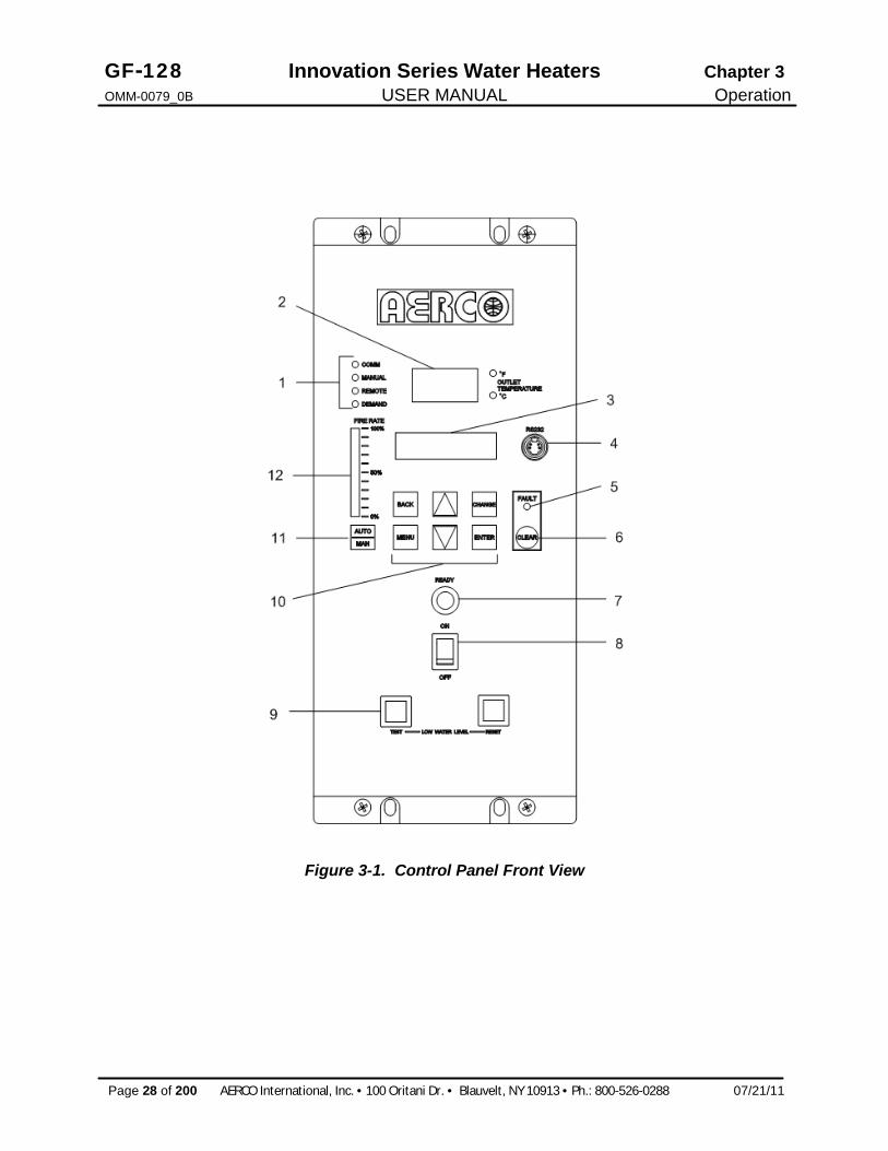
3.2 CONTROL PANEL DESCRIPTION The Innovation Control Panel shown in Figure 3-1 contains all of the controls, indicators and displays necessary to operate, adjust and troubleshoot the Innovation Water Heater. These operating controls, indicators and displays are listed and described in Table 3-1. Additional information on these items is provided in the individual operating procedures provided in this Chapter.
GF-128 Innovation Series Water Heaters Chapter 3 OMM-0079_0B USER MANUAL Operation
Page 28 of 200 AERCO International, Inc. · 100 Oritani Dr. · Blauvelt, NY 10913 · Ph.: 800-526-0288 07/21/11
Figure 3-1. Control Panel Front View

Chapter 3 Innovation Series Water Heaters GF-128 Operation USER MANUAL OMM-0079_0B
07/21/11 AERCO International, Inc. · 100 Oritani Dr. · Blauvelt, NY 10913 · Ph: 800-526-0288 Page 29 of 200
Table 3-1 Operating Controls, Indicators and Displays
ITEM NO.
CONTROL, INDICATOR OR DISPLAY
FUNCTION
1 LED Status Indicators Four Status LEDs indicate the current operating status as follows:
COMM Lights when RS-232 communication is occurring
MANUAL Lights when the unit is being controlled using the front panel keypad.
REMOTE Lights when the unit is being controlled by an external signal from an Energy Management System
DEMAND Lights when there is a demand for heat.
2 OUTLET TEMPERATURE Display
3–Digit, 7–Segment LED display continuously displays the outlet water temperature. The °F or °C LED next to the display lights to indicate whether the displayed temperature is in degrees Fahrenheit or degrees Celsius. The °F or °C blinks when operating in the Deadband Mode.
3 VFD Display Vacuum Fluorescent Display (VFD) consists of 2 lines each capable of displaying up to 16 alphanumeric characters. The information displayed includes: Startup Messages Fault Messages Operating Status Messages Menu Selection
4 RS-232 Port Port permits a Laptop Computer or External Modem to be connected to the unit’s Control Panel.
5 FAULT Indicator Red FAULT LED indicator lights when a heater alarm condition occurs. An alarm message will appear in the VFD.
6 CLEAR Key Turns off the FAULT indicator and clears the alarm message if the alarm is no longer valid. Lockout type alarms will be latched and cannot be cleared by simply pressing this key. Troubleshooting may be required to clear these types of alarms.
7 READY Indicator Lights ON/OFF switch is set to ON and all Pre-Purge conditions have been satisfied.
8 ON/OFF Switch Enables and disables heater operation.
9 LOW WATER LEVEL TEST/RESET Switches
Allows operator to test operation of the water level monitor. Pressing TEST opens the water level probe circuit and simulates a Low Water Level alarm. Pressing RESET resets the water level monitor circuit. Pressing the CLEAR key (item 6) resets the display.

GF-128 Innovation Series Water Heaters Chapter 3 OMM-0079_0B USER MANUAL Operation
Page 30 of 200 AERCO International, Inc. · 100 Oritani Dr. · Blauvelt, NY 10913 · Ph.: 800-526-0288 07/21/11
Table 3-1 Operating Controls, Indicators and Displays – Continued ITEM NO.
CONTROL, INDICATOR OR DISPLAY
FUNCTION
10 MENU Keypad Consists of 6 keys which provide the following functions for the Control Panel Menus:
MENU Steps through the main menu categories shown in Figure 3-2. The Menu categories wrap around in the order shown.
BACK Allows you to go back to the previous menu level without changing any information. Continuously pressing this key will bring you back to the default status display in the VFD. Also, this key allows you to go back to the top of a main menu category.
▲ (UP) Arrow When in one of the main menu categories (Figure 3-2), pressing the ▲ arrow key will select the displayed menu category. If the CHANGE key was pressed and the menu item is flashing, pressing the ▲ arrow key will increment the selected setting.
▼ (DOWN) Arrow When in one of the main menu categories (Figure 3-2), pressing this key will select the displayed menu category. If the CHANGE key was pressed and the menu item is flashing, pressing the ▼ arrow key will decrement the selected setting.
CHANGE Permits a setting to be changed (edited). When the CHANGE key is pressed, the displayed menu item will begin to flash. Pressing the ▲ or ▼ arrow key when the item is flashing will increment or decrement the displayed setting.
ENTER Saves the modified menu settings in memory. The display
will stop flashing.
11 AUTO/MAN Switch This switch toggles the heater between the Automatic and Manual modes of operation. When in the Manual (MAN) mode, the front panel controls are enabled and the MANUAL status LED lights. When in the Automatic (AUTO) mode, the MANUAL status LED will be off and the front panel controls disabled.
12 VALVE POSITION Bargraph
20 segment red LED bargraph continuously shows the Air/Fuel Valve position in 5% increments from 0 to 100%

Chapter 3 Innovation Series Water Heaters GF-128 Operation USER MANUAL OMM-0079_0B
07/21/11 AERCO International, Inc. · 100 Oritani Dr. · Blauvelt, NY 10913 · Ph: 800-526-0288 Page 31 of 200
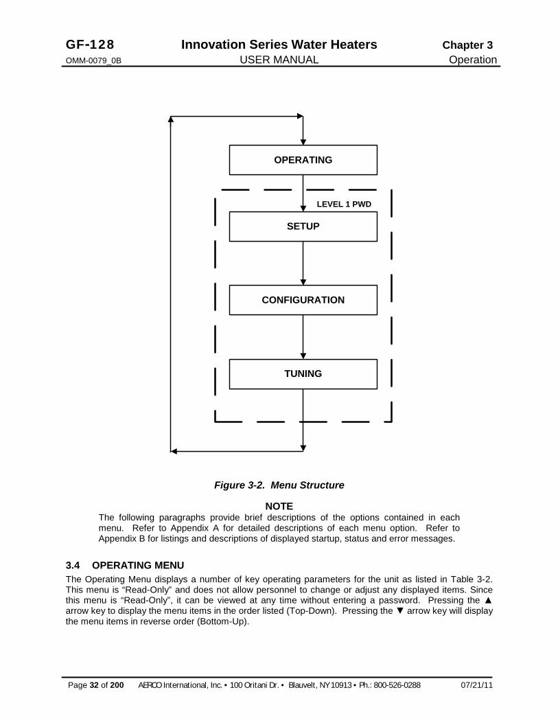
3.3 CONTROL PANEL MENUS The Control Panel incorporates an extensive menu structure which permits the operator to set up, and configure the unit. The menu structure consists of five major menu categories which are applicable to this manual. These categories are shown in Figure 3-2. Each of the menus shown, contain options which permit operating parameters to be viewed or changed. The menus are protected by a password levels to prevent unauthorized use.
Prior to entering the correct password, the options contained in the Operation, Setup, Configuration and Tuning Menu categories can be viewed. However, with the exception of Internal Setpoint Temperature (Configuration Menu), none of the viewable menu options can be changed.
Once the valid level 1 password (159) is entered, the options listed in the Setup. Configuration and Tuning Menus can be viewed and changed, if desired.
3.3.1 Menu Processing Procedure Accessing and initiating each menu and option is accomplished using the Menu Keys shown in Figure 3-1. Therefore, it is imperative that you be thoroughly familiar with the following basic steps before attempting to perform specific menu procedures.
1. The Control Panel will normally be in the Operating Menu and the VFD will display the current unit status. Pressing the ▲ or ▼ arrow key will display the other available data items in the Operating Menu.
2. Press the MENU key. The display will show the Setup Menu, which is the next menu category shown in Figure 3-2. This menu contains the Password option which must be entered if other menu options will be changed.
3. Continue pressing the MENU key until the desired menu is displayed.
4. With the desired menu displayed, press the ▲ or ▼ arrow key. The first option in the selected menu will be displayed.
5. Continue to press the ▲ or ▼ arrow key until the desired menu option is displayed. Pressing the ▲ arrow key will display the available menu options in the Top-Down sequence. Pressing the ▼ arrow key will display the options in the Bottom-Up sequence. The menu options will wrap-around after the first or last available option is reached.
6. To change the value or setting of a displayed menu option, press the CHANGE key. The displayed option will begin to flash. Press the ▲ or ▼ arrow key to scroll through the available menu option choices for the option to be changed. The menu option choices do not wrap around.
7. To select and store a changed menu item, press the ENTER key.
GF-128 Innovation Series Water Heaters Chapter 3 OMM-0079_0B USER MANUAL Operation
Page 32 of 200 AERCO International, Inc. · 100 Oritani Dr. · Blauvelt, NY 10913 · Ph.: 800-526-0288 07/21/11
OPERATING
SETUP
CONFIGURATION
TUNING
LEVEL 1 PWD
Figure 3-2. Menu Structure
NOTE The following paragraphs provide brief descriptions of the options contained in each menu. Refer to Appendix A for detailed descriptions of each menu option. Refer to Appendix B for listings and descriptions of displayed startup, status and error messages.
3.4 OPERATING MENU The Operating Menu displays a number of key operating parameters for the unit as listed in Table 3-2. This menu is “Read-Only” and does not allow personnel to change or adjust any displayed items. Since this menu is “Read-Only”, it can be viewed at any time without entering a password. Pressing the ▲ arrow key to display the menu items in the order listed (Top-Down). Pressing the ▼ arrow key will display the menu items in reverse order (Bottom-Up).

Chapter 3 Innovation Series Water Heaters GF-128 Operation USER MANUAL OMM-0079_0B
07/21/11 AERCO International, Inc. · 100 Oritani Dr. · Blauvelt, NY 10913 · Ph: 800-526-0288 Page 33 of 200
3.5 SETUP MENU The Setup Menu (Table 3-3) permits the operator to enter the unit password (159) which is required to change the menu options. To prevent unauthorized use, the password will time-out after 1 hour. Therefore, the correct password must be reentered when required. In addition to permitting password entries, the Setup Menu is also used to enter date and time, units of temperature measurements and entries required for external communication and control of the unit via the RS-232 port. A view-only software version display is also provided to indicate the current Control Box software version.
NOTE The Outdoor Temp display item shown with an asterisk in Table 3-2 will not be displayed unless the Outdoor Sensor function has been enabled in the Configuration Menu (Table 3-4).
Table 3-2. Operating Menu
Available Choices or Limits Menu Item Display Minimum Maximum Default
Status Message
Active Setpoint 40°F 240°F
Inlet Temp 40°F 140°F
AIR Temp -70°F 245°F
Outdoor Temp* -70°F 130°F
Valve Position In 0% 100%
Valve Position Out 0% 100%
FFWD Temp 80°F 160°F
Flame Strength 0% 100%
Run Cycles 0 999,999,999
Run Hours 0 999,999,999
Fault Log 0 19 0
Table 3-3. Setup Menu Available Choices or Limits
Menu Item Display Minimum Maximum Default Passsword 0 9999 0
Language English English
Time 12:00 am 11:59 pm
Date 01/01/00 12/31/99
Unit of Temp Fahrenheit or Celsius Fahrenheit
Comm Address 0 127 0
Baud Rate 2400, 4800, 9600, 19.2K 9600
Software Ver 0.00 Ver 9.99

GF-128 Innovation Series Water Heaters Chapter 3 OMM-0079_0B USER MANUAL Operation
Page 34 of 200 AERCO International, Inc. · 100 Oritani Dr. · Blauvelt, NY 10913 · Ph.: 800-526-0288 07/21/11
3.6 CONFIGURATION MENU The Configuration Menu shown in Table 3-4 permits adjustment of the Internal Setpoint (Setpt) temperature regardless of whether the valid password has been entered. Setpt is required for operation in the Constant Setpoint mode. The remaining options in this menu require the valid password to be entered, prior to changing existing entries. This menu contains a number of other configuration settings which may or may not be displayed, depending on the current operating mode setting.
NOTE The Configuration Menu settings shown in Table 3-4 are Factory-Set in accordance with the requirements specified for each individual order. Therefore, under normal operating conditions, no changes will be required.
Table 3-4. Configuration Menu Available Choices or Limits
Menu Item Display Minimum Maximum Default Internal Setpt Lo Temp
Limit Hi Temp Limit 130°F
Unit Type KC Boiler, KC Boiler LN, BMK Boiler, BMK Boiler LN, BMK Boiler Dual, KC Water
Heater, KC Water Heater LN, INN
INN
Unit Size
0.5 MBTU, 1.0 MBTU 1.5 MBTU, 2.0 MBTU 3.0 MBTU, 3.5 MBTU 4.0 MBTU, 5.0 MBTU
6.0 MBTU
1.0 MBTU
Fuel Type Natural Gas, Propane Natural Gas
Water Heater Mode Constant Setpoint, Remote Setpoint,
Constant Setpoint
Remote Signal (If Mode = Remote Setpoint, Direct Drive or Combination)
4 – 20 mA/1 – 5V 0 -20 mA/0 – 5V
PWM Input (BMS) Network
4 – 20 mA, 1-5V
Bldg Ref Temp (If Mode = Outdoor Reset)
40°F 230°F 70°F
Reset Ratio (If Mode = Outdoor Reset)
0.1 9.9 1.2
Outdoor Sensor Enabled or Disabled Disabled
System Start Tmp (If Outdoor Sensor = Enabled)
30°F 100°F 60°F
Chapter 3 Innovation Series Water Heaters GF-128 Operation USER MANUAL OMM-0079_0B
07/21/11 AERCO International, Inc. · 100 Oritani Dr. · Blauvelt, NY 10913 · Ph: 800-526-0288 Page 35 of 200
Table 3-4. Configuration Menu - Continued Available Choices or Limits
Menu Item Display Minimum Maximum Default Setpt Lo Limit 40°F Setpt Hi Limit 60°F
Setpt Hi Limit Setpt Lo Limit 220°F 140°F
Temp Hi Limit 40°F 240°F 160°F
Max Valve Position 40% 100% 100%
Pump Delay Timer 0 min. 30 min. 0 min.
Aux Start On Dly 0 sec. 120 sec. 0 sec.
Failsafe Mode Shutdown or Constant Setpt Shutdown
*Analog Output (See CAUTION at end of Table 3-4 )
Off, Setpoint, Outlet Temp, Valve Position 4-20 mA,
Valve Position 0-10V
*Valve Position 0-10V
Low Fire Timer 2 sec. 600 sec. 2 sec.
Setpt Limiting Enabled or Disabled Disabled
Setpt Limit Band 0°F 10°F 0
Network Timeout 5 Sec 999 Sec 30 Sec
HI DB Setpt EN 0% 100% 30%
Demand Offsert 0 25 0
Deadband High 0 25 0
Deadband Low 0 25 0 *CAUTION:
DO NOT CHANGE the Analog Output Menu Item from its Default setting (Valve Position 0-10V).
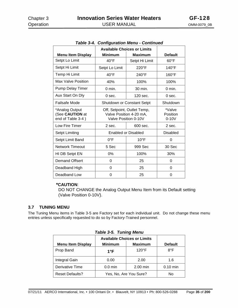
3.7 TUNING MENU The Tuning Menu items in Table 3-5 are Factory set for each individual unit. Do not change these menu entries unless specifically requested to do so by Factory-Trained personnel.
Table 3-5. Tuning Menu Available Choices or Limits
Menu Item Display Minimum Maximum Default Prop Band 1°F 120°F 8°F
Integral Gain 0.00 2.00 1.6
Derivative Time 0.0 min 2.00 min 0.10 min
Reset Defaults? Yes, No, Are You Sure? No
GF-128 Innovation Series Water Heaters Chapter 3 OMM-0079_0B USER MANUAL Operation
Page 36 of 200 AERCO International, Inc. · 100 Oritani Dr. · Blauvelt, NY 10913 · Ph.: 800-526-0288 07/21/11
3.8 START SEQUENCE When the Control Box ON/OFF switch is set to the ON position, it checks all pre-purge safety switches to ensure they are closed. These switches include:
· Safety Shut-Off Valve Proof of Closure (POC) switch · Low Water Level switch · High Water Temperature switch · High Gas Pressure switch · Low Gas Pressure switch · Blower Proof switch If all of the above switches are closed, the READY light above the ON/OFF switch will light and the unit will be in the Standby mode.
When there is a demand for hot water, the following events will occur:
NOTE If any of the Pre-Purge safety device switches are open, the appropriate fault message will be displayed. Also, the appropriate messages will be displayed throughout the start sequence, if the required conditions are not observed.
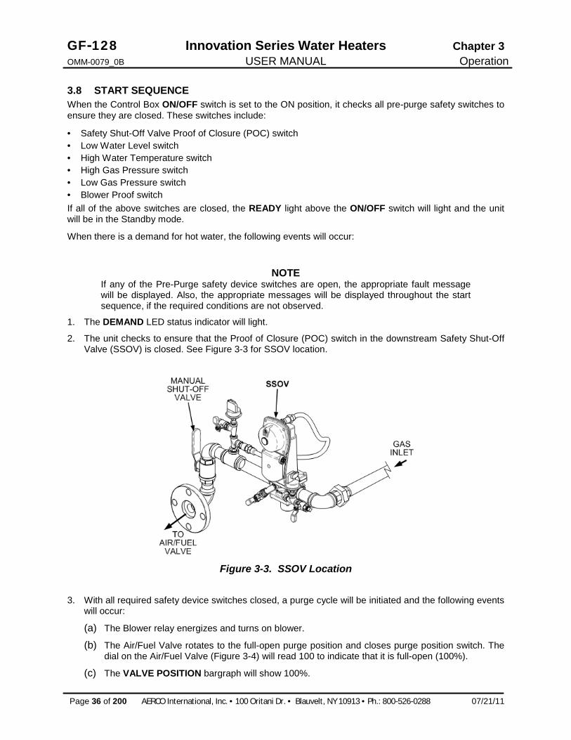
1. The DEMAND LED status indicator will light.
2. The unit checks to ensure that the Proof of Closure (POC) switch in the downstream Safety Shut-Off Valve (SSOV) is closed. See Figure 3-3 for SSOV location.
Figure 3-3. SSOV Location
3. With all required safety device switches closed, a purge cycle will be initiated and the following events will occur:
(a) The Blower relay energizes and turns on blower.
(b) The Air/Fuel Valve rotates to the full-open purge position and closes purge position switch. The dial on the Air/Fuel Valve (Figure 3-4) will read 100 to indicate that it is full-open (100%).
(c) The VALVE POSITION bargraph will show 100%.

Chapter 3 Innovation Series Water Heaters GF-128 Operation USER MANUAL OMM-0079_0B
07/21/11 AERCO International, Inc. · 100 Oritani Dr. · Blauvelt, NY 10913 · Ph: 800-526-0288 Page 37 of 200
Figure 3-4. Air/Fuel Valve In Purge Position
4. Next, the blower proof switch on the Air/Fuel Valve (Figure 3-5) closes. The display will show Purging and indicate the elapsed time of the purge cycle in seconds.
Figure 3-5. Blower Proof Switch
5. Upon completion of the purge cycle, the Control Box initiates an ignition cycle and the following events occur:
(a) The Air/Fuel Valve rotates to the low-fire ignition position and closes the ignition switch. The dial on the Air/Fuel Valve (Figure 3-6) will read between 25 and 35 to indicate that the valve is in the low-fire position.
(b) The igniter relay is activated and provides ignition spark.
(c) The gas Safety Shut-Off Valve (SSOV) is energized (opened) allowing gas to flow into the Air/Fuel Valve.
GF-128 Innovation Series Water Heaters Chapter 3 OMM-0079_0B USER MANUAL Operation
Page 38 of 200 AERCO International, Inc. · 100 Oritani Dr. · Blauvelt, NY 10913 · Ph.: 800-526-0288 07/21/11
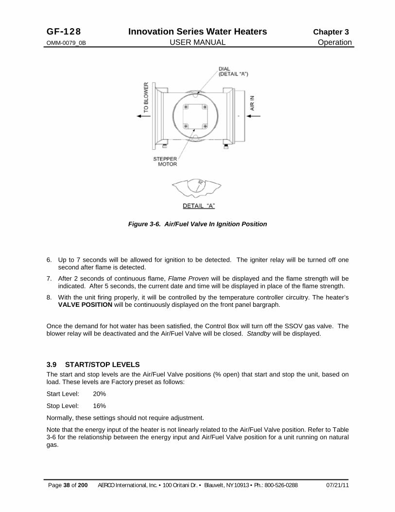
Figure 3-6. Air/Fuel Valve In Ignition Position
6. Up to 7 seconds will be allowed for ignition to be detected. The igniter relay will be turned off one second after flame is detected.
7. After 2 seconds of continuous flame, Flame Proven will be displayed and the flame strength will be indicated. After 5 seconds, the current date and time will be displayed in place of the flame strength.
8. With the unit firing properly, it will be controlled by the temperature controller circuitry. The heater’s VALVE POSITION will be continuously displayed on the front panel bargraph.
Once the demand for hot water has been satisfied, the Control Box will turn off the SSOV gas valve. The blower relay will be deactivated and the Air/Fuel Valve will be closed. Standby will be displayed.
3.9 START/STOP LEVELS The start and stop levels are the Air/Fuel Valve positions (% open) that start and stop the unit, based on load. These levels are Factory preset as follows:
Start Level: 20%
Stop Level: 16%
Normally, these settings should not require adjustment.
Note that the energy input of the heater is not linearly related to the Air/Fuel Valve position. Refer to Table 3-6 for the relationship between the energy input and Air/Fuel Valve position for a unit running on natural gas.

Chapter 3 Innovation Series Water Heaters GF-128 Operation USER MANUAL OMM-0079_0B
07/21/11 AERCO International, Inc. · 100 Oritani Dr. · Blauvelt, NY 10913 · Ph: 800-526-0288 Page 39 of 200
Table 3-6. Relationship Between Air/Fuel Valve Position and Energy Input For Unit Running On Natural Gas
Air/Fuel Valve Position (% Open)
Energy Input (BTU/Hr)
Heater Energy Input (% of Full Capacity)
0% 0 0 10% 0 0 16%
(Stop Level) 45,000 4.2%
20% 97,000 10% 30% 222,000 22% 40% 416,000 42% 50% 520,000 52% 60% 645,000 65% 70% 715,000 72% 80% 845,000 85% 90% 930,000 93%
100% 1,060,000 100%

GF-128 Innovation Series Water Heaters Chapter 4 OMM-0079_0B USER MANUAL Initial Start-Up
Page 40 of 200 AERCO International, Inc. · 100 Oritani Dr. · Blauvelt, NY 10913 · Ph.: 800-526-0288 07/21/11
This Page Is Intentionally Blank

Chapter 4 Innovation Series Water Heaters GF-128 Initial Start-Up USER MANUAL OMM-0079_0B
07/21/11 AERCO International, Inc. · 100 Oritani Dr. · Blauvelt, NY 10913 · Ph: 800-526-0288 Page 41 of 200
CHAPTER 4. INITIAL START-UP 4.1 INITIAL START-UP REQUIREMENTS The requirements for the initial start-up of the Innovation Water Heater consists of the following:
· Complete installation (Chapter 2) · Set proper controls and limits (Chapter 3) · Perform combustion calibration · Test safety devices (Chapter 5)
All applicable installation procedures in Chapter 2 must be fully completed prior to performing the initial start-up of the unit. The initial start-up must be successfully completed prior to putting the unit into service. Starting a unit without the proper piping, venting, or electrical systems can be dangerous and may void the product warranty. The following start-up instructions should be followed precisely in order to operate the unit safely and at a high thermal efficiency, with low flue gas emissions.
Initial unit start-up must be performed ONLY by AERCO factory trained start-up and service personnel. After performing the start-up procedures in this Chapter, it will be necessary to perform the Safety Device Testing procedures specified in Chapter 5 to complete all initial unit start-up requirements.
An AERCO Gas Fired Startup Sheet, included with each Innovation Heater, must be completed for each unit for warranty validation and a copy must be returned promptly to AERCO at: AERCO International, Inc. 100 Oritani Drive Blauvelt, New York 10913
WARNING DO NOT ATTEMPT TO DRY FIRE THE HEATER. STARTING THE UNIT WITHOUT A FULL WATER LEVEL CAN SERIOUSLY DAMAGE THE UNIT AND MAY RESULT IN INJURY TO PERSONNEL OR PROPERTY DAMAGE. THIS SITUATION WILL VOID ANY WARRANTY.
4.2 TOOLS AND INSTRUMENTATION FOR COMBUSTION CALIBRATION To properly perform combustion calibration, the proper instruments and tools must be used and correctly attached to the unit. The following paragraphs outline the necessary tools and instrumentation as well as their installation.
4.2.1 Required Tools & Instrumentation The following tools and instrumentation are necessary to perform combustion calibration of the unit:
· Digital Combustion Analyzer: Oxygen accuracy to ± 0.4%; Carbon Monoxide (CO) and Nitrogen Oxide (NOx) resolution to 1PPM.
· 16 inch W.C. manometer or equivalent gauge and plastic tubing.
· 1/8 inch NPT-to-barbed fittings for use with gas supply manometer or gauge.
· Small and large flat blade screwdrivers.
· Tube of silicone adhesive

GF-128 Innovation Series Water Heaters Chapter 4 OMM-0079_0B USER MANUAL Initial Start-Up
Page 42 of 200 AERCO International, Inc. · 100 Oritani Dr. · Blauvelt, NY 10913 · Ph.: 800-526-0288 07/21/11
4.2.2 Installing Gas Supply Manometer The gas supply manometer is installed in the gas train as follows:
1. Close the main manual gas supply shut-off valve upstream of the unit.
2. Remove the front door and left side panels from the heater to access the gas train components.
3. Remove the 1/8 inch NPT pipe plug from the leak detection ball valve on the downstream side of the Safety Shut Off Valve (SSOV) as shown in Figure 4-1.
4. Install a NPT-to-barbed fitting into the tapped plug port.
5. Attach one end of the plastic tubing to the barbed fitting and the other end to the 16 inch W.C. manometer.
Figure 4-1. 1/8 Inch Gas Plug Location
4.2.3 Accessing the Analyzer Probe Port The unit contains a 1/8” NPT port at the rear of the exhaust manifold. This port is located above the condensate drain connection as shown in Figure 4-2. Prepare the port for the combustion analyzer probe as follows:
1. Refer to Figure 4-2 and remove the 1/8” NPT plug from the rear of the exhaust manifold.
2. If necessary, adjust the stop on the combustion analyzer probe so it will extend mid-way into the flue gas flow. DO NOT install the probe at this time.
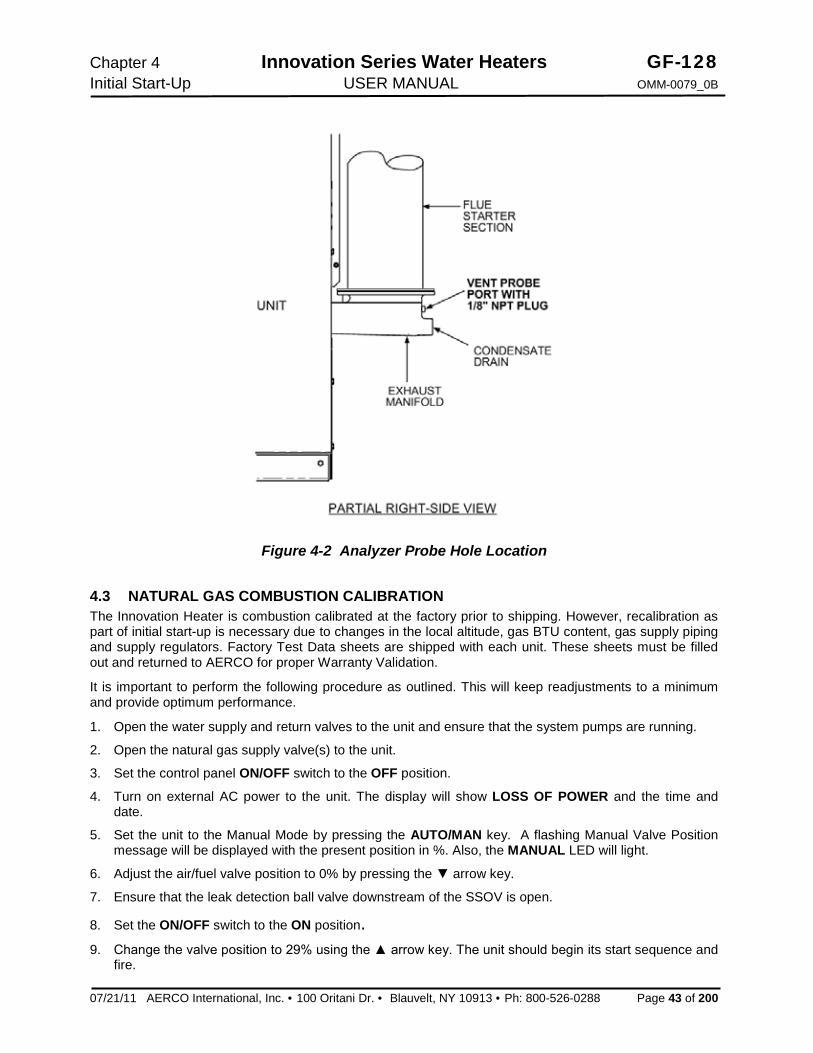
Chapter 4 Innovation Series Water Heaters GF-128 Initial Start-Up USER MANUAL OMM-0079_0B
07/21/11 AERCO International, Inc. · 100 Oritani Dr. · Blauvelt, NY 10913 · Ph: 800-526-0288 Page 43 of 200
Figure 4-2 Analyzer Probe Hole Location
4.3 NATURAL GAS COMBUSTION CALIBRATION The Innovation Heater is combustion calibrated at the factory prior to shipping. However, recalibration as part of initial start-up is necessary due to changes in the local altitude, gas BTU content, gas supply piping and supply regulators. Factory Test Data sheets are shipped with each unit. These sheets must be filled out and returned to AERCO for proper Warranty Validation.
It is important to perform the following procedure as outlined. This will keep readjustments to a minimum and provide optimum performance.
1. Open the water supply and return valves to the unit and ensure that the system pumps are running.
2. Open the natural gas supply valve(s) to the unit.
3. Set the control panel ON/OFF switch to the OFF position.
4. Turn on external AC power to the unit. The display will show LOSS OF POWER and the time and date.
5. Set the unit to the Manual Mode by pressing the AUTO/MAN key. A flashing Manual Valve Position message will be displayed with the present position in %. Also, the MANUAL LED will light.
6. Adjust the air/fuel valve position to 0% by pressing the ▼ arrow key.
7. Ensure that the leak detection ball valve downstream of the SSOV is open.
8. Set the ON/OFF switch to the ON position. 9. Change the valve position to 29% using the ▲ arrow key. The unit should begin its start sequence and
fire.

GF-128 Innovation Series Water Heaters Chapter 4 OMM-0079_0B USER MANUAL Initial Start-Up
Page 44 of 200 AERCO International, Inc. · 100 Oritani Dr. · Blauvelt, NY 10913 · Ph.: 800-526-0288 07/21/11
10. Next, verify that the gas pressure downstream of the SSOV is within the range of 2.6” to 2.8” W.C. If gas pressure adjustment is required, remove the brass hex nut on the SSOV actuator to access the gas pressure adjustment screw (Figure 4-3). Make gas pressure adjustments using a flat-tip screwdriver to obtain a gas pressure within the required range of 2.6” to 2.8” W.C.
Figure 4-3. Gas Pressure Adjustment Screw Location
11. Using the ▲ arrow key, Increase the valve open position to 100%. Verify that the gas pressure at the inlet of the SSOV is 7.0” W.C. Readjust the inlet gas pressure if necessary.
12. Next, decrease the valve open position to 16% using the ▼ arrow key.
13. Insert the combustion analyzer probe int the 1/8” port at the rear of the exhaust manifold. Allow enough time for the combustion analyzer to settle.
14. Verify that the oxygen (O2) level is within the range shown below Also, ensure that the carbon monoxide (CO) and nitrogen oxide (NOx) readings do not exceed the values shown.
Combustion Oxygen Level at
16% Valve Position Oxygen %
± 0.5 Carbon
Monoxide
NOx 6.5 % <50 ppm <15 ppm
15. If the oxygen level is not within the required tolerance, the gas pressure on the downstream side of the
SSOV must be adjusted using the adjustment screw on the SSOV regulator (Figure 4-3). Slowly rotate the gas pressure adjustment (approximately 1/4-turn increments). Allow the combustion analyzer to stabilize following each adjustment. Clockwise rotation reduces the oxygen level, while counterclockwise rotation increases the oxygen level.
16. Once the oxygen level is within the required range, the gas pressure on the downstream side of the SSOV should be within the range of 2.6” to 2.8” W.C. at the 16% valve position.
17. Replace the brass cap on the SSOV gas pressure adjustment if it was previously removed.
18. This completes the combustion calibration procedure.

Chapter 4 Innovation Series Water Heaters GF-128 Initial Start-Up USER MANUAL OMM-0079_0B
07/21/11 AERCO International, Inc. · 100 Oritani Dr. · Blauvelt, NY 10913 · Ph: 800-526-0288 Page 45 of 200
4.4 REASSEMBLY Once the combustion calibration adjustments are properly set, the unit can be reassembled for service operation.
1. Set the ON/OFF switch in the OFF position.
2. Disconnect AC power from the unit.
3. Shut off the gas supply to the unit.
4. Remove the manometer and barbed fittings and reinstall the NPT plug using a suitable pipe thread compound.
5. Remove the combustion analyzer probe from the 1/8” vent hole in the exhaust manifold. Replace the 1/8” NPT plug in the manifold.
6. Replace the unit’s side panels and front door.
4.5 TEMPERATURE CONTROL CALIBRATION Although the unit comes factory set and calibrated for a 130°F setpoint it is usually necessary to recalibrate temperature control. There are two primary adjustments for performing temperature calibration. These are Min Load Adj and Max Load Adj (minimum and maximum load adjustment).
Adjustments to these settings are made at minimum and maximum load conditions and should be made in small increments from 1 to 3 degrees. After making an adjustment, the outlet water temperature must be allowed to settle for several minutes prior to making any further adjustments.
When calibrating temperature control, observe the following:
1. The unit must be in the Auto mode of operation.
2. The Outlet Feedback option in the Tuning Menu must be set to OFF while performing calibration.
3. Monitor the OUTLET TEMPERATURE display and VALVE POSITION bar-graph to set load conditions and observe the effect of adjustments.
4. Perform the calibration using the Tuning Menu of the C-More Control Box.
5. Make small adjustments and allow time between adjustments for the outlet water temperature to stabilize.
6. Maintain water flow as constant as possible during these adjustments.
7. Ensure that recirculation loops are operational while the calibration is being performed. 4.5.1 Setting the Outlet Water Temperature Setpoint The setpoint temperature of the unit may be changed by following the procedure below. However, once a setpoint has been changed, recalibration may be necessary. The temperature calibration procedures are provided in paragraphs 4.5.2 and 4.5.3.
To adjust the unit’s setpoint, proceed as follows:
1. Press the MENU key until Configuration Menu is displayed.
2. Press the ▲ or ▼ arrow key until Internal Setpt is displayed along with the present setpoint temperature.
3. To change the setpoint, press the CHANGE key. The display will begin to flash.
4. Press the ▲ or ▼ arrow key until the desired setpoint is displayed.
5. Press the ENTER key to save the change.

GF-128 Innovation Series Water Heaters Chapter 4 OMM-0079_0B USER MANUAL Initial Start-Up
Page 46 of 200 AERCO International, Inc. · 100 Oritani Dr. · Blauvelt, NY 10913 · Ph.: 800-526-0288 07/21/11
4.5.2 Minimum Load Adjustment With the unit in operation, check the temperature control at minimum load as follows:
1. While monitoring the VALVE POSITION bar-graph, create a minimum load on the system that will yield a steady valve position between 25% and 35%.
NOTE It may be desirable to shut off the outlet valve and use the hose bib (see Figure 2-4) to simulate a minimum flow load condition.
2. Wait several minutes to allow the outlet temperature to stabilize under load conditions.
3. Once stabilized, the OUTLET TEMPERATURE display should read no more than 2 to 3 degrees above the unit’s setpoint.
4. If the outlet temperature is stabilized, proceed to the Maximum Load Adjustment procedure in paragraph 4.5.3. If the temperature is not stabilized, proceed to step 5.
5. Press the MENU key and select the Tuning Menu.
6. Press the ▲ or ▼ arrow key until Min Load Adj is displayed.
7. Press the CHANGE key. The display will begin to flash.
8. Raise or lower the minimum load adjustment in increments of one or two using the ▲ or ▼ arrow key. Increasing this value will increase outlet water temperature, while decreasing it will decrease outlet water temperature.
9. Press ENTER to save the change. Allow time for the system to stabilize between adjustments
10. Repeat steps 5 through 9 as needed until the temperature is stabilized at no more than 2 to 3 degrees above the unit’s setpoint.
4.5.3 Maximum Load Adjustment Check the temperature control at maximum load as follows:
1. While monitoring the VALVE POSITION bar-graph, create a maximum load on the system that will yield a steady valve position between 80% and 90%.
NOTE It may be necessary to open the outlet valve if it was closed during minimum load adjustment to obtain a sufficient flow rate for maximum adjustment.
2. Wait several minutes to allow the outlet water temperature to stabilize under load conditions.
3. Once stabilized, the OUTLET TEMPERATURE display should read no more than 2 to 3 degrees below the unit’s setpoint.
4. If the outlet temperature is stabilized, no adjustment is necessary. If the temperature is not stabilized, proceed to step 5.
5. Press the MENU key and select the Tuning Menu.
6. Press the ▲ or ▼ arrow key until Max Load Adj is displayed.
7. Press the CHANGE key. The display will begin to flash.
8. Raise or lower the maximum load adjustment using the ▲ or ▼ arrow key. Increasing this value will increase outlet water temperature, while decreasing it will decrease water temperature.
9. Press ENTER to save the change. Allow time for the system to stabilize between adjustments.

Chapter 4 Innovation Series Water Heaters GF-128 Initial Start-Up USER MANUAL OMM-0079_0B
07/21/11 AERCO International, Inc. · 100 Oritani Dr. · Blauvelt, NY 10913 · Ph: 800-526-0288 Page 47 of 200
10. Repeat steps 5 through 9 as needed until the temperature is stabilized 2 to 3 degrees below the unit’s setpoint.
If the outlet temperature does not maintain setpoint after a reasonable amount of time and adjustment, contact your local AERCO representative.
NOTE: After performing Temperature Calibration and prior to placing the water heater into service, be sure to set the Outlet Feedback option in the Tuning Menu back to ON.
4.6 OVER-TEMPERATURE LIMIT SWITCHES The unit contains both automatic and manual reset over-temperature limit switches. These switches are mounted on a plate as shown in Figure 4-4. The switches can be accessed by opening the front panel door of the unit. The manual reset switch is not adjustable and is permanently fixed at 200°F. This switch will shut down and lock out the heater if the water temperature exceeds 200°F. Following an over-temperature condition, it must be manually reset by pressing the RESET button before the heater can be restarted. The automatic reset over-temperature switch is adjustable and allows the unit to restart, once the temperature drops below its temperature setting. Set the automatic over-temperature switch to the desired setting.
Figure 4-4. Over Temperature Limit Switch Location

GF-128 Innovation Series Water Heaters Chapter 4 OMM-0079_0B USER MANUAL Initial Start-Up
Page 48 of 200 AERCO International, Inc. · 100 Oritani Dr. · Blauvelt, NY 10913 · Ph.: 800-526-0288 07/21/11
This Page Is Intentionally Blank

Chapter 5 Innovation Series Water Heaters GF-128 Safety Device Testing USER MANUAL OMM-0079_0B
07/21/11 AERCO International, Inc. · 100 Oritani Dr. · Blauvelt, NY 10913 · Ph: 800-526-0288 Page 49 of 200
CHAPTER 5. SAFETY DEVICE TESTING
5.1 TESTING OF SAFETY DEVICES Periodic safety device testing is required to ensure that the control system and safety devices are operating properly. The heater control system comprehensively monitors all combustion-related safety devices before, during and after the start sequence. The following tests check to ensure that the system is operating as designed.
Operating controls and safety devices should be tested on a regular basis or following service or replacement. All testing must conform to local codes such as ASME CSD-1.
NOTE MANUAL and AUTO modes of operation are required to perform the following tests. For a complete explanation of these modes, see Chapter 3.
NOTE It will be necessary to remove the front door and side panels from the unit to perform the following tests.
WARNING ELECTRICAL VOLTAGES IN THIS SYSTEM MAY INCLUDE 120 AND 24 VOLTS AC. POWER MUST BE REMOVED PRIOR TO PERFORMING WIRE REMOVAL OR OTHER TEST PROCEDURES THAT CAN RESULT IN ELECTRICAL SHOCK.
5.2 LOW GAS PRESSURE FAULT TEST Refer to Figure 5-1 and ensure that the leak detection ball valve located at the high gas pressure switch is closed.
1. Remove the 1/8“ plug from the ball valve at the low gas pressure switch shown in the lower portion of Figure 5-1.
2. Install a 0 – 16“ W.C. manometer or a W.C. gauge where the 1/8" plug was removed.
3. Slowly open the ball valve near the low gas pressure switch.
4. Place the unit in Manual Mode and adjust the air/fuel valve position (% open) between 25 and 30%.
5. While the unit is firing, slowly close the external manual gas shut-off valve.
6. The unit should shut down and display a LOW GAS PRESSURE fault message at approximately 2.6” W.C. The FAULT indicator should also start flashing.
7. Fully open the external manual gas shut-off valve and press the CLEAR button on the Control Box.
8. The fault message should clear and the FAULT indicator should go off. The unit should restart.
9. Upon test completion, close the ball valve and remove the manometer. Replace the 1/8“ plug removed in step 1.

GF-128 Innovation Series Water Heaters Chapter 5 OMM-0079_0B USER MANUAL Safety Device Testing
Page 50 of 200 AERCO International, Inc. · 100 Oritani Dr. · Blauvelt, NY 10913 · Ph.: 800-526-0288 07/21/11
Figure 5-1. Low & High Gas Pressure Testing
5.3 HIGH GAS PRESSURE TEST To simulate a high gas pressure fault, refer to Figure 5-1 and proceed as follows:
1. Remove the 1/8“ plug from the leak detection ball valve shown in Figure 5-1.
2. Install a 0 – 16” W.C. manometer (or W.C. gauge) where the 1/8” plug was removed.
3. Slowly open the leak detection ball valve
4. Start the unit in Manual mode at a valve position (firing rate) of 25%.
5. Slowly increase the gas pressure using the adjustment screw on the SSOV.
6. The unit should shut down and display a HIGH GAS PRESSURE fault message when the gas pressure exceeds 4.0” W.C. The FAULT indicator should also start flashing.
7. Reduce the gas pressure back to 2.8” W.C.
8. Press the CLEAR button on the Control Box to clear the fault.
9. The fault message should clear and the FAULT indicator should go off. The unit should restart.
10. Upon test completion, close the ball valve and remove the manometer. Replace the 1/8“ plug removed in step 1.
5.4 LOW WATER LEVEL FAULT TEST To simulate a low water level fault:
1. Set the ON/OFF switch to the OFF position
2. Close the water shut-off valves in the supply and return piping to the unit.
3. Slowly open the drain valve on the rear of the unit. If necessary the unit’s relief valve may be opened to aid in draining.
4. Continue draining the unit until a LOW WATER LEVEL fault message is displayed and the FAULT indicator flashes.
5. Place the unit in the Manual Mode and raise the valve position above 30%.

Chapter 5 Innovation Series Water Heaters GF-128 Safety Device Testing USER MANUAL OMM-0079_0B
07/21/11 AERCO International, Inc. · 100 Oritani Dr. · Blauvelt, NY 10913 · Ph: 800-526-0288 Page 51 of 200
6. Set the ON/OFF switch to the ON position. The READY light should remain off and the unit should not start. If the unit does start, shut the unit off immediately and refer fault to qualified service personnel.
7. Close the drain and pressure relief valve used in draining the unit.
8. Open the water shut-off valve in the return piping to the unit.
9. Open the water supply shut-off valve to the unit to refill.
10. After the shell is full, press the LOW WATER LEVEL RESET button to reset the low water cutoff.
11. Press the CLEAR button to reset the FAULT LED and clear the displayed error message.
12. Set the ON/OFF switch to the ON position. The unit is now ready for operation. 5.5 WATER TEMPERATURE FAULT TEST A high water temperature fault is simulated by adjusting the automatic over-temperature switch. This switch is accessible from the front of the unit as shown in Figure 5-2.
1. Start the unit in the normal operating mode. Allow the unit to stabilize at its setpoint.
2. Lower the adjustable over-temperature switch setting to match the displayed OUTLET TEMPERATURE.
3. Once the adjustable over-temperature switch setting is approximately at, or just below, the actual outlet water temperature, the unit should shut down. The FAULT indicator should start flashing and a HIGH WATER TEMP SWITCH OPEN fault message should be displayed. It should not be possible to restart the unit.
4. Reset the adjustable over-temperature switch to its original setting.
5. The unit should start once the adjustable temperature limit switch setting is above the actual outlet water temperature.
6. Once the adjustable over-temperature switch setting is approximately at, or just below, the actual outlet water temperature, the unit should shut down. The FAULT indicator should start flashing and a HIGH WATER TEMP SWITCH OPEN fault message should be displayed. It should not be possible to restart the unit.
7. Reset the adjustable over-temperature switch to its original setting.
8. The unit should start once the adjustable temperature limit switch setting is above the actual outlet water temperature.
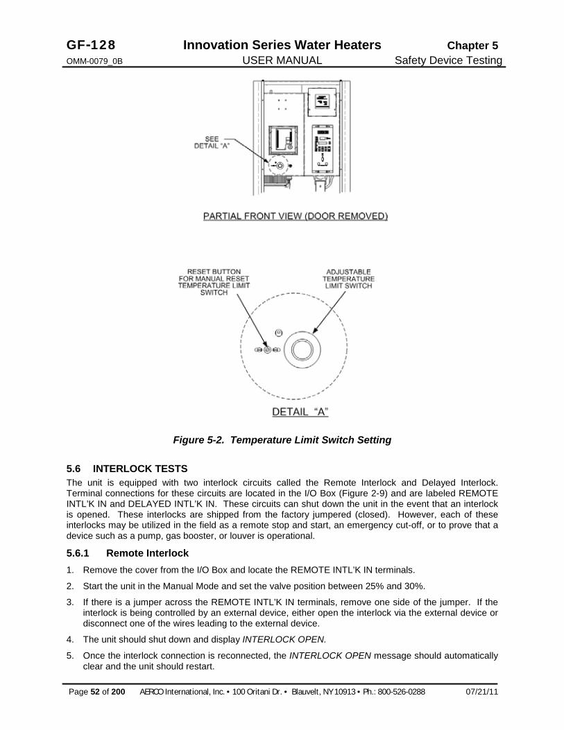
GF-128 Innovation Series Water Heaters Chapter 5 OMM-0079_0B USER MANUAL Safety Device Testing
Page 52 of 200 AERCO International, Inc. · 100 Oritani Dr. · Blauvelt, NY 10913 · Ph.: 800-526-0288 07/21/11
Figure 5-2. Temperature Limit Switch Setting
5.6 INTERLOCK TESTS The unit is equipped with two interlock circuits called the Remote Interlock and Delayed Interlock. Terminal connections for these circuits are located in the I/O Box (Figure 2-9) and are labeled REMOTE INTL’K IN and DELAYED INTL’K IN. These circuits can shut down the unit in the event that an interlock is opened. These interlocks are shipped from the factory jumpered (closed). However, each of these interlocks may be utilized in the field as a remote stop and start, an emergency cut-off, or to prove that a device such as a pump, gas booster, or louver is operational.
5.6.1 Remote Interlock 1. Remove the cover from the I/O Box and locate the REMOTE INTL’K IN terminals.
2. Start the unit in the Manual Mode and set the valve position between 25% and 30%.
3. If there is a jumper across the REMOTE INTL’K IN terminals, remove one side of the jumper. If the interlock is being controlled by an external device, either open the interlock via the external device or disconnect one of the wires leading to the external device.
4. The unit should shut down and display INTERLOCK OPEN.
5. Once the interlock connection is reconnected, the INTERLOCK OPEN message should automatically clear and the unit should restart.

Chapter 5 Innovation Series Water Heaters GF-128 Safety Device Testing USER MANUAL OMM-0079_0B
07/21/11 AERCO International, Inc. · 100 Oritani Dr. · Blauvelt, NY 10913 · Ph: 800-526-0288 Page 53 of 200
5.6.2 Delayed Interlock 1. Remove the cover from the I/O Box and locate the DELAYED INTL’K IN terminals (see Figure 2-12).
2. Start the unit in the Manual Mode at a valve position between 25% and 30%.
3. If there is a jumper across the DELAYED INTL’K IN terminals, remove one side of the jumper. If the interlock is connected to a proving switch of an external device, disconnect one of the wires leading to the proving switch.
4. The unit should shut down and display a DELAYED INTERLOCK OPEN fault message. The FAULT LED should be flashing.
5. Reconnect the wire or jumper removed in step 3 to restore the interlock.
6. Press the CLEAR button to reset the fault.
7. The unit should start.
5.7 FLAME FAULT TESTS Flame faults can occur during ignition or while the unit is already running. To simulate each of these fault conditions, proceed as follows:
1. Set the ON/OFF switch to the OFF position.
2. Place the unit in the Manual Mode and set the valve position between 25% and 30%.
3. Close the manual gas shutoff valve located between the Safety Shut-Off Valve (SSOV) and the Air/Fuel Valve (see Figure 5-3).
4. Set the ON/OFF switch to the ON position to start the unit.
5. The unit should shut down after reaching the Ignition cycle and display FLAME LOSS DURING IGN.
6. Open the valve previously closed in step 3 and press the CLEAR button.
7. Restart the unit and allow it to prove flame.
8. Once flame is proven, close the 1” manual gas shut-off valve located between the SSOV (Figure 5-3) and the Air/Fuel Valve.
9. The unit should shut down and execute an IGNITION RETRY cycle by performing the following steps: (a) The unit will execute a shutdown purge cycle for a period of 15 seconds and display WAIT
FAULT PURGE. (b) The unit will execute a 30 second re-ignition delay and display WAIT RETRY PAUSE. (c) The unit will then execute a standard ignition sequence and display WAIT IGNITION RETRY.
10. Since the manual gas shutoff valve is still closed, the unit will shut down and display FLAME LOSS DURING IGNITION following the IGNITION RETRY cycle.
11. Open the valve previously closed in step 8.
12. Press the CLEAR button. The unit should restart and fire.

GF-128 Innovation Series Water Heaters Chapter 5 OMM-0079_0B USER MANUAL Safety Device Testing
Page 54 of 200 AERCO International, Inc. · 100 Oritani Dr. · Blauvelt, NY 10913 · Ph.: 800-526-0288 07/21/11
Figure 5-3. Manual Gas Shut-Off Valve Location 5.8 AIR FLOW FAULT TESTS These tests check the operation of the Blower Proof Switch and Blocked Inlet Switch shown in Figure 5-4.
1. Disable the blower output drive voltage as follows: (a) Press the MENU key until CONFIGURATION MENU is displayed. (b) Press the ▲ arrow key until the ANALOG OUTPUT function is displayed, then press the
CHANGE key. (c) Press the ▼ arrow key until OFF is displayed, then press the ENTER key.
2. Start the unit in the Manual Mode at a valve position of 25%.
3. The unit should shut down and execute an IGNITION RETRY cycle by performing the following steps: (a) The unit will execute a 30 second re-ignition delay and display WAIT RETRY PAUSE. (b) The unit will then execute a standard ignition sequence and display WAIT IGNITION RETRY.
4. The unit should perform two IGNITION RETRY cycles and then shut down on the third successive ignition attempt. The unit will display AIRFLOW FAULT DURING PURGE.
5. Re-enable the blower output drive voltage by performing the following steps: (a) Press the MENU key until CONFIGURATION MENU is displayed. (b) Press the ▲ arrow key until the ANA-LOG OUTPUT function is displayed, then press the
CHANGE key. (c) Press the ▲ arrow key until VALVE POSITION 0-10V is displayed, then press the ENTER key.
6. Once the unit has proved flame, turn off the blower by going to the Configuration Menu, Analog Output menu item and select OFF.
7. The Blower Proof Switch will open and the blower should stop. The unit should shut down and display AIRFLOW FAULT DURING RUN.
8. Go to the Configuration Menu, Analog Output item and select VALVE POSITION 0-10v.
9. Press the CLEAR button. The unit should restart.

Chapter 5 Innovation Series Water Heaters GF-128 Safety Device Testing USER MANUAL OMM-0079_0B
07/21/11 AERCO International, Inc. · 100 Oritani Dr. · Blauvelt, NY 10913 · Ph: 800-526-0288 Page 55 of 200
10. Next, check the operation of the Blocked Inlet Switch located on the inlet side of the Air/Fuel Valve
(Figure 5-4).
11. Ensure that the sheet metal panels are securely installed on the water heater and the unit is running.
12. At the rear of the unit, partially block the air inlet (Figure 5-5) with a plywood sheet or metal plate.
13. The unit should shut down and again display AIRFLOW FAULT DURING RUN.
14. Unblock the air inlet and press the CLEAR button. The unit should restart.
Figure 5-4. Blower Proof & Blocked Inlet Switch Locations 6.
7. 8.
Figure 5-5. Water Heater Rear View Showing Air Inlet Location

GF-128 Innovation Series Water Heaters Chapter 5 OMM-0079_0B USER MANUAL Safety Device Testing
Page 56 of 200 AERCO International, Inc. · 100 Oritani Dr. · Blauvelt, NY 10913 · Ph.: 800-526-0288 07/21/11
5.9 SSOV PROOF OF CLOSURE SWITCH The SSOV shown in Figure 5-1 contains the proof of closure switch. The proof of closure switch circuit is checked as follows:
1. Set the unit’s ON/OFF switch to the OFF position.
2. Place the unit in Manual Mode and set the valve position between 25% and 30%
3. Refer to Figure 5-1 and locate the SSOV.
4. Remove the cover from the SSOV by loosening the screw shown in Figure 5-6. Lift off the cover to access the terminal wiring connections.
5. Disconnect wire #148 from the SSOV to “open” the proof of closure switch circuit.
6. The unit should fault and display SSOV SWITCH OPEN.
7. Replace wire #148 and press the CLEAR button.
8. Set the ON/OFF switch to ON to start the unit.
9. Remove the wire again when the unit reaches the purge cycle and PURGING is displayed.
10. The unit should shut down and display SSOV FAULT DURING PURGE.
11. Replace the wire on the SSOV and press the CLEAR button. The unit should restart.
Figure 5-6. SSOV Actuator Cover Location 5.10 PURGE SWITCH OPEN DURING PURGE The Purge Switch (and Ignition Switch) is located on the Air/Fuel Valve. To check the switch, proceed as follows:
1. Set the unit’s ON/OFF switch to the OFF position. Place the unit in manual mode and set the valve position between 25% and 30%.
2. Remove the Air/Fuel Valve cover by rotating the cover counterclockwise to unlock it (see Figure 5-7).
3. Remove one of the two wires (#171 or #172) from the Purge Switch (Figure 5-8).
4. Initiate a unit start sequence.
5. The unit should begin it’s start sequence, then shut down and display PRG SWITCH OPEN DURING PURGE.
6. Replace the wire on the Purge Switch and depress the CLEAR button. The unit should restart.

Chapter 5 Innovation Series Water Heaters GF-128 Safety Device Testing USER MANUAL OMM-0079_0B
07/21/11 AERCO International, Inc. · 100 Oritani Dr. · Blauvelt, NY 10913 · Ph: 800-526-0288 Page 57 of 200
5.11 IGNITION SWITCH OPEN DURING IGNITION The Ignition Switch (and the Purge Switch) is located on the Air/Fuel Valve. To check the switch, proceed as follows:
1. Set the unit’s ON/OFF switch to the OFF position.
2. Place the unit in Manual Mode and set the valve position between 25% and 30%.
3. Remove the Air/Fuel Valve cover (Figure 5-5) by rotating the cover counterclockwise to unlock and lift up to remove.
4. Remove one of the two wires (#169 or #170) from the Ignition Switch (Figure 5-8).
5. Initiate a unit start sequence.
6. The unit should begin it’s start sequence and then shut down and display IGN SWITCH OPEN DURING IGNITION.
7. Replace the wire on the Ignition Switch and press the CLEAR button. The unit should restart.
Figure 5-7. Typical Air/Fuel Valve Cover Location
Figure 5-8. Air/Fuel Valve Purge and Ignition Switch Locations

GF-128 Innovation Series Water Heaters Chapter 5 OMM-0079_0B USER MANUAL Safety Device Testing
Page 58 of 200 AERCO International, Inc. · 100 Oritani Dr. · Blauvelt, NY 10913 · Ph.: 800-526-0288 07/21/11
5.12 SAFETY PRESSURE RELIEF VALVE TEST Test the safety Pressure Relief Valve in accordance with ASME Pressure Vessel Code, Section VI.

Chapter 6 Innovation Series Water Heaters GF-128 Maintenance USER MANUAL OMM-0079_0B
07/21/11 AERCO International, Inc. · 100 Oritani Dr. · Blauvelt, NY 10913 · Ph: 800-526-0288 Page 59 of 200
CHAPTER 6. MAINTENANCE
6.1 MAINTENANCE SCHEDULE The Innovation Water Heater requires regular routine maintenance to ensure continued reliable operation throughout the service life of the unit. For optimum operation, AERCO recommends that the following routine maintenance procedures be performed in the time periods specified in Table 6-1.
Appendix I contains a list of the recommended spare parts for maintenance of the Innovation Heater.
WARNING TO AVOID PERSONAL INJURY, PRIOR TO SERVICING ENSURE THAT THE FOLLOWING GUIDELINES ARE STRICTLY OBSERVED: · DISCONNECT THE AC SUPPLY BY TURNING OFF THE SERVICE
SWITCH AND AC SUPPLY CIRCUIT BREAKER. · SHUT OFF THE GAS SUPPLY AT THE MANUAL SHUT-OFF VALVE
PROVIDED WITH THE UNIT · ALLOW THE UNIT TO COOL TO A SAFE WATER TEMPERATURE TO
PREVENT BURNING OR SCALDING
TABLE 6-1 - MAINTENANCE SCHEDULE
PARAGRAPH ITEM 6 Mos. 12 Mos. 24 Mos. Labor Time
6.2 Igniter-Injector (58023) *Inspect Inspect Replace 15 mins.
6.3 Flame Detector (66018) *Inspect Inspect Replace 15 mins.
6.4 Combustion Calibration *Check Check 1 hr.
6.5 Testing of Safety
Devices Test 20 mins.
6.6 Fireside Inspection Inspect &
Clean 2 hrs.
6.7 Waterside Inspection Inspect 1 hr.
6.8 Heat Exchanger
Cleaning Clean 2 hrs.
6.9 Condensate Drain Trap *Inspect Inspect &
Clean 30 mins.
6.10 Air Filter (59138) Replace 5 mins.
* Only performed after initial 6 month period after initial startup.

GF-128 Innovation Series Water Heaters Chapter 6 OMM-0079_0B USER MANUAL Maintenance
Page 60 of 200 AERCO International, Inc. · 100 Oritani Dr. · Blauvelt, NY 10913 · Ph.: 800-526-0288 07/21/11
6.2 IGNITER-INJECTOR The igniter-injector (part no. 58023) is located on the flange of the blower-side intake manifold located at the bottom of the unit’s heat exchanger. In addition to providing the ignition spark required to light the burner, the igniter-injector also contains a gas injector tube which connects to the staged ignition assembly. Figure 6-1 shows the blower-side intake manifold removed from the heater and indicates the locations of the igniter-injector, flame detector and other related components.
The igniter-injector may be hot, therefore, care should be exercised to avoid burns. It is easier to remove the igniter-injector from the unit after the unit has cooled to room temperature.
Figure 6-1. Blower-Side intake Manifold (Shown Removed from Heater)
To inspect/replace the Igniter-Injector:
1. Set the ON/OFF switch on the control panel, to the OFF position. Disconnect AC power from the unit
2. Remove the side and rear panels from the unit.
3. Disconnect the cable from the igniter-injector (Figure 6-1).
4. Refer to the partial exploded view in Figure 6-1 and Figure 6-2. Using a 7/16” open-end wrench, disconnect the compression nut securing the gas injector tube of the igniter-injector to the elbow of the staged ignition solenoid assembly. Disconnect the staged ignition assembly from the igniter-injector.
5. Next, loosen and remove the igniter-injector from the intake manifold flange using a 1" open-end wrench.
6. Check the igniter-injector for evidence of erosion or carbon build-up. If there is evidence of substantial erosion or carbon build-up, the igniter-injector should be replaced. If carbon build-up is present, clean the component using fine emery cloth. Repeated carbon build-up is an indication that the combustion settings of the unit should be checked. Refer to Chapter 4 for combustion calibration procedures.
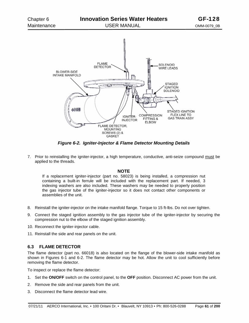
Chapter 6 Innovation Series Water Heaters GF-128 Maintenance USER MANUAL OMM-0079_0B
07/21/11 AERCO International, Inc. · 100 Oritani Dr. · Blauvelt, NY 10913 · Ph: 800-526-0288 Page 61 of 200
Figure 6-2. Igniter-Injector & Flame Detector Mounting Details
7. Prior to reinstalling the igniter-injector, a high temperature, conductive, anti-seize compound must be applied to the threads.
NOTE If a replacement igniter-injector (part no. 58023) is being installed, a compression nut containing a built-in ferrule will be included with the replacement part. If needed, 3 indexing washers are also included. These washers may be needed to properly position the gas injector tube of the igniter-injector so it does not contact other components or assemblies of the unit.
8. Reinstall the igniter-injector on the intake manifold flange. Torque to 15 ft-lbs. Do not over tighten.
9. Connect the staged ignition assembly to the gas injector tube of the igniter-injector by securing the compression nut to the elbow of the staged ignition assembly.
10. Reconnect the igniter-injector cable.
11. Reinstall the side and rear panels on the unit. 6.3 FLAME DETECTOR The flame detector (part no. 66018) is also located on the flange of the blower-side intake manifold as shown in Figures 6-1 and 6-2. The flame detector may be hot. Allow the unit to cool sufficiently before removing the flame detector.
To inspect or replace the flame detector:
1. Set the ON/OFF switch on the control panel, to the OFF position. Disconnect AC power from the unit.
2. Remove the side and rear panels from the unit.
3. Disconnect the flame detector lead wire.

GF-128 Innovation Series Water Heaters Chapter 6 OMM-0079_0B USER MANUAL Maintenance
Page 62 of 200 AERCO International, Inc. · 100 Oritani Dr. · Blauvelt, NY 10913 · Ph.: 800-526-0288 07/21/11
4. Remove the two (2) screws securing the flame detector to the intake manifold (Figures 6-1 and 6-2). The flame detector is secured to the burner intake manifold with one (1) #10-32 screw and one (1) #8-32 screw.
5. Remove the flame detector and gasket from the manifold flange.
6. Thoroughly inspect the flame detector. If eroded, the detector should be replaced. Otherwise, clean the detector with a fine emery cloth.
7. Reinstall the flame detector and flame detector gasket.
8. Reconnect the flame detector lead wire.
9. Reinstall the side and rear panels on the unit. 6.4 COMBUSTION CALIBRATION Combustion settings must be checked at the intervals shown in Table 6-1 as part of the maintenance requirements. Refer to Chapter 4 for combustion calibration instructions.
6.5 SAFETY DEVICE TESTING Systematic and thorough tests of the operating and safety devices should be performed to ensure that they are operating as designed. Also, certain code requirements specify that these tests be performed on a scheduled basis. Test schedules must conform to local jurisdictions. The results of the tests should be recorded in a log book. See Chapter 5 for Safety Device Test Procedures.
6.6 FIRESIDE INSPECTION Fireside inspection of the Innovation Water Heater will include removal of the exhaust manifold, Blower-side intake manifold, and the burner assembly from the Innovation Water Heater.
The purpose of this inspection is to check for the formation of deposits on the inside of the heat exchanger tubes, exhaust manifold, and/or the burner assembly. These deposits can be caused by the presence of even trace amounts of chlorides and/or sulfur, in the combustion air and fuel sources. Such deposits can be influenced by the extent of the condensing operation and the chloride and sulfur levels that can vary significantly from application to application.
Since the fireside inspection will include removal of the exhaust manifold, burner assembly and blower-side intake manifold from the Innovation Water Heater, the following replacement gaskets will be necessary for reassembly upon completion of the inspection:
Part No. Description 18899 Burner Flange Gasket 81048 Flame Detector Gasket 18899 Burner Gasket 124749 Fiber Frax Gasket 161151 Combustion Chamber Liner
(If damaged)
The blower-side intake manifold may be hot. Therefore, allow the unit to cool sufficiently before starting the removal process described in the following steps
1. Set the ON/OFF switch on the control panel, to the OFF position. Disconnect AC power from the unit and turn off the gas supply.
2. Remove the side and rear panels from the unit.
3. Refer to Figures 6-2 and 6-3 to locate the blower-side intake manifold (part no. 44106) at the bottom of the unit's heat exchanger.
4. Disconnect the lead wire from the flame detector installed on the intake manifold flange (Figure 6-2).

Chapter 6 Innovation Series Water Heaters GF-128 Maintenance USER MANUAL OMM-0079_0B
07/21/11 AERCO International, Inc. · 100 Oritani Dr. · Blauvelt, NY 10913 · Ph: 800-526-0288 Page 63 of 200
5. Remove the two (2) screws securing the flame detector to the blower-side intake manifold (24234).
The flame detector is secured to the manifold with one (1) #10-32 screw and one (1) #8-32 screw.
6. Remove the flame detector and gasket from the blower side intake manifold flange.
7. Disconnect the cable from the igniter-injector which is also installed on the blower-side intake manifold flange.
8. Using a 7/16” open-end wrench, disconnect the compression nut securing the gas injector tube of the igniter-injector to the elbow of the staged ignition assembly (see Figure 6-2). Disconnect the staged ignition assembly from the igniter-injector.
9. Next, loosen and remove the igniter-injector from the intake manifold flange using a 1" open-end wrench.
10. Refer to Figure 6-3. Loosen and remove the four (4) 1/4-20 cap screws securing the blower side of the intake manifold (44106). DO NOT REMOVE the two 1/4-20 screws and nuts securing the manifold support bracket.
Figure 6-3. Blower-Side Intake Manifold & Exhaust Manifold Locations
CAUTION The intake manifold, burner and exhaust manifold assemblies weigh approximately 25 pounds. Use care when removing these assemblies in the following steps.
11. While supporting the blower-side intake manifold, loosen and remove the six (6) 5/16-18 hex nuts securing it to the studs protruding from the exhaust manifold.
12. Carefully lower and remove the blower side intake manifold (44106), burner assembly (46023), burner gasket (18899) and fiber frax gasket (124749) from the unit. See Figures 6-3 and 6-4.

GF-128 Innovation Series Water Heaters Chapter 6 OMM-0079_0B USER MANUAL Maintenance
Page 64 of 200 AERCO International, Inc. · 100 Oritani Dr. · Blauvelt, NY 10913 · Ph.: 800-526-0288 07/21/11
13. Disconnect the exhaust temperature sensor (Figure 6-3) by unscrewing it from the exhaust manifold.
14. While supporting the exhaust manifold, remove the two (2) side nuts (Figure 6-5) securing the manifold to the heat exchanger. Loosen, but DO NOT REMOVE the third nut nearest to the front of the unit.
15. Remove the exhaust manifold (44085) from the unit.
16. Inspect the exhaust manifold and burner assemblies for debris. Clean out debris as necessary.
17. Using a flashlight, inspect the combustion chamber liner (161151) shown in Figure 6-5. Replace the liner if there is evidence of cracking or warping.
18. This completes the fireside inspection of the unit.
Figure 6-4. Innovation Heater – Partial Left-Side View
Figure 6-5. Innovation Heater – Partial Cut-Away View

Chapter 6 Innovation Series Water Heaters GF-128 Maintenance USER MANUAL OMM-0079_0B
07/21/11 AERCO International, Inc. · 100 Oritani Dr. · Blauvelt, NY 10913 · Ph: 800-526-0288 Page 65 of 200
Figure 6-6. Combustion Chamber Liner & Gasket Locations
IMPORTANT Prior to reassembly, ensure that the combustion chamber liner is installed prior to reinstalling the exhaust manifold. During reassembly, apply high-temperature, anti-seize lubricant to the threads of the igniter-injector and grounding screw. Also, ensure that the igniter-injector and staged ignition assembly are properly positioned and are not contacting other components. Torque the igniter-injector to 15 ft-lbs.
19. Beginning with the exhaust manifold assembly removed in step 15, reinstall all the components in the reverse order that they were removed.
6.7 WATERSIDE INSPECTION The waterside of the heating surfaces may be inspected by removal of the top heater head. (See Figure 6-6). Prior to performing the inspection, ensure that the following replacement gaskets are available:
GP-18556 Release Gasket GP-18532 Shell Gasket
To inspect the waterside of the heat exchanger, proceed as follows:

GF-128 Innovation Series Water Heaters Chapter 6 OMM-0079_0B USER MANUAL Maintenance
Page 66 of 200 AERCO International, Inc. · 100 Oritani Dr. · Blauvelt, NY 10913 · Ph.: 800-526-0288 07/21/11
1. Disconnect the electrical power to the unit.
2. Close the water inlet, outlet, and recircuation shut-off valves to the unit. 3. Carefully open the drain valve while opening the relief valve on the rear of the unit to relieve pressure
and allow air into the shell.
4. Remove the wing nut from the top center of the shell cap and remove the cap.
5. Remove the nuts and cap screws from the upper head. Remove the upper head and upper head-liner, (See Figure 6-7).
6. Inspect and clean the heat exchanger tubes of scale and all gasket surfaces thoroughly before reassembling the upper head. AERCO recommends that NEW gaskets be used when reassembling.
7. Place a shell head gasket on top of the shell ring first, then place the release gasket on top of the shell head gasket. Align the gasket holes with those in the shell ring.
8. Place the upper head liner on top of the gaskets.
9. Place the upper head on next aligning the holes.
10. Reassemble the cap screws and nuts through the upper head and shell ring. Cross tighten the nuts to approximately 75 ft.-lb. torque to obtain a uniform seating, then progressively tighten the nuts to 150 ft.-lb.
11. Replace the unit Cap. Close the drain valve and reopen the inlet, outlet, and recirculation valve.
Figure 6-7. Flat Style Head Configuration

Chapter 6 Innovation Series Water Heaters GF-128 Maintenance USER MANUAL OMM-0079_0B
07/21/11 AERCO International, Inc. · 100 Oritani Dr. · Blauvelt, NY 10913 · Ph: 800-526-0288 Page 67 of 200
6.8 HEAT EXCHANGER CLEANING AERCO recommends that the heat exchanger of the unit be cleaned annually using a solution of Hydroskrub and water. Hydroskrub is distributed by AERCO International, Inc. and is designed to dissolve the toughest water scale, lime, mud and rust deposits from virtually any type of water-based equipment.
NOTE The following cleaning procedure applies to all sizes WWDW and SWDW Heaters. For Helical Coil Type Water Heaters, refer to the applicable manuals listed in Section 1, page 1-8 of this document for cleaning/descaling procedures.
CAUTION Please review MSDS, specifications, and our website (www.aerco.com) for additional information, or call technical service at (800) 526-0288.
CAUTION Do not drain the unit without venting the shell! A vacuum in the unit may displace the liner causing serious damage not covered by warranty.
6.8.1 Pumping System Set-Up Instructions A sample pumping set-up diagram is shown in Figure 6-8 for an Innovation Water Heater. As this diagram shows, heat exchanger cleaning is accomplished by pumping the HydroSkrub solution from a large circulating bucket to the heat exchanger drain valve, through the heat exchanger and then out through the output connection of the heater. Set up the pumping system as follows: 1. Turn off the water heater and close the inlet and outlet isolation valves.
2. Open the drain valve at the rear of the heater and drain at least half of the heat exchanger water-side volume. When full Innovation models INN800 and INN1060 hold approximately 22 gallons of water. Therefore, drain 11 gallons of water from the heat exchanger.
3. Prepare a 50% solution of Hydroskrub and clean water. The amount of the solution should be approximately equal to the full volume of water that the heat exchanger holds.
4. Mix 11 gallons of HydroSkrub with 11 gallons of water to provide a 50% solution.
5. Close the unit drain valve and connect a suitable size bucket and pump to the unit drain as shown in Figure 6-8.
6. Install a “T”, ball valve and hose connection in the outlet piping of the heater (Figure 6-8). Route the hose back to the top of the circulation bucket.

GF-128 Innovation Series Water Heaters Chapter 6 OMM-0079_0B USER MANUAL Maintenance
Page 68 of 200 AERCO International, Inc. · 100 Oritani Dr. · Blauvelt, NY 10913 · Ph.: 800-526-0288 07/21/11
Figure 6-8. Sample Heat Exchanger Cleaning Set-Up 6.8.2 Cleaning Procedure 1. Slowly add the prescribe amount of the Hydroskrub solution to the circulating bucket.
2. Open the drain valve, outlet hose connection valve and turn on the pump. Periodically check for leaks and maintain the liquid level in the bucket. A lowering volume level is an indication that there is an open drain in the system.
3. Check the cleaning circuit to ensure that the HydroSkrub solution is flowing from the circulation bucket, through the pump and the heater and back to the top of the top of the bucket.
4. Return discharge foaming indicates an active HydroSkrub solution and the presence of mineral deposits in the equipment.
5. Additional HydroSkrub and/or water may be required to maintain circulation and to prevent the pump from cavitating.
6. Circulate the cleaning solution through the heat exchanger and piping for 1 to 3 hours. Estimate the circulation period based on the time in service and water hardness. When the foaming action stops, HydroSkrub strength is depleted (two pounds of deposits removed per gallon used) or the equipment is free from calcium and other water-formed mineral deposits.
7. Periodically test the solution for effectiveness to determine if more HydroSkrub is needed. Refer to “Testing HydroSkrub Effectiveness” in the next paragraph for details. If the cleaning solution is expended before circulation time is up, additional HydroSkrub will be needed and circulation time may be extended to complete the cleaning.
8. Upon completion of the cleaning process, begin flushing the solution by adding clean water to the circulation bucket, then disconnect the return valve and hose connection from the top of the circulating bucket and thoroughly flush. Continue water flushing the equipment for a minimum of 10 minutes or until discharge runs clear.

Chapter 6 Innovation Series Water Heaters GF-128 Maintenance USER MANUAL OMM-0079_0B
07/21/11 AERCO International, Inc. · 100 Oritani Dr. · Blauvelt, NY 10913 · Ph: 800-526-0288 Page 69 of 200
9. HydroSkrub is biodegradable, and in most instances may be purged down sewers. Check with local
authorities before disposing of any complex compositions
10. Turn off water, shut off the pump and immediately close discharge valves to prevent backflow.
11. Completely drain pump bucket. Disconnect the hoses from equipment and thoroughly rinse the bucket, pump, and associated hoses used.
6.8.3 Testing HydroSkrub Effectiveness There are two methods of testing the effectiveness of HydroSkrub during cleaning: the calcium carbonate spot test of the circulating solution and the charting of a trend in the pH of the cleaning solution.
Calcium Carbonate Spot Test A calcium carbonate spot test is performed by exposing a form of calcium carbonate to the HydroSkrub solution. Samples of the deposit, a Tums or Rolaids tablet, or bare concrete can be used. Observe the reaction of the HydroSkrub solution on the calcium carbonate. Foaming and bubbling indicates the solution is still active. Little or no reaction indicates that the solution is expended. This test should be performed near the end of the circulating time. If the solution has been expended, more HydroSkrub will be required to complete the job. If the solution is still active at the end of the time, all the scale has been dissolved.
pH Trend Charting The initial pH of the cleaning solution will measure between 1-3 (See pH sheet on HydroSkrub packaging). To test the effectiveness of the circulating solution as a function of pH, take readings at regular intervals and chart as a trend. Note that the deposits can cause a premature jump in the pH. After circulating for approximately 75% of the cycle time, begin testing the pH at 10-15 minute intervals. Once the solution’s pH reads 6.0-7.0 on three or more consecutive readings, the solution is expended. If the pH reads below 6.0 after the circulating time, the application is clean.
6.9 CONDENSATE DRAIN TRAP The Innovation Water Heater contains a condensate trap as shown in Chapter 2, Figure 2-7. The trap is located external to the unit and attached to the drain connection from the exhaust manifold. This trap should be inspected and, if necessary, cleaned to ensure proper operation. To inspect and clean the trap, proceed as follows:
1. Disconnect the external condensate trap by loosening the union pipe connection between the trap and the exhaust manifold drain.
2. Remove the connections on the inlet and outlet sides of the condensate trap shown in Figure 6-9.
3. Loosen the four (4) thumbscrews securing the cover on the condensate trap. Remove the cover.
4. Remove the float from the condensate trap.
5. Remove the orifice gasket from the trap.
6. Thoroughly clean the trap, float and gasket. Also inspect the drain piping for blockage. If the trap cannot be thoroughly cleaned, replace the trap.
7. After the above items have been thoroughly cleaned and inspected, replace the orifice gasket and float in the condensate trap and replace the trap cover.
8. Reassemble all piping and hose connections to the condensate trap inlet and outlet. Reconnect the trap to exhaust manifold drain.

GF-128 Innovation Series Water Heaters Chapter 6 OMM-0079_0B USER MANUAL Maintenance
Page 70 of 200 AERCO International, Inc. · 100 Oritani Dr. · Blauvelt, NY 10913 · Ph.: 800-526-0288 07/21/11
Figure 6-9. External Condensate Trap 6.10 AIR FILTER REPLACEMENT The Innovation heater is equipped with an air filter (part no. 59138) which should be replaced every 12 months. The air filter is located at the inlet of the air fuel valve as shown in Figure 6-10.
To inspect/replace the air filter, proceed as follows:
To inspect/replace the Igniter-Injector:
1. Set the ON/OFF switch on the control panel, to the OFF position. Disconnect AC power from the unit
2. Remove the side panels from the unit.
3. Refer to Figure 6-10 and locate the air filter attached to the air/fuel valve inlet.
4. Using a flat-tip screwdriver or 5/16” nut driver, loosen the clamp securing the filter to the inlet flange of the air/fuel valve. Remove the filter and clamp.
5. Each replacement air filter is equipped with its own clamp. Therefore, simply install the replacement air filter on inlet flange of the air fuel valve and tighten the clamp with a flat-tip screwdriver or 5/16” nut driver.
6. Replace the side panels on the unit and return heater to service use.
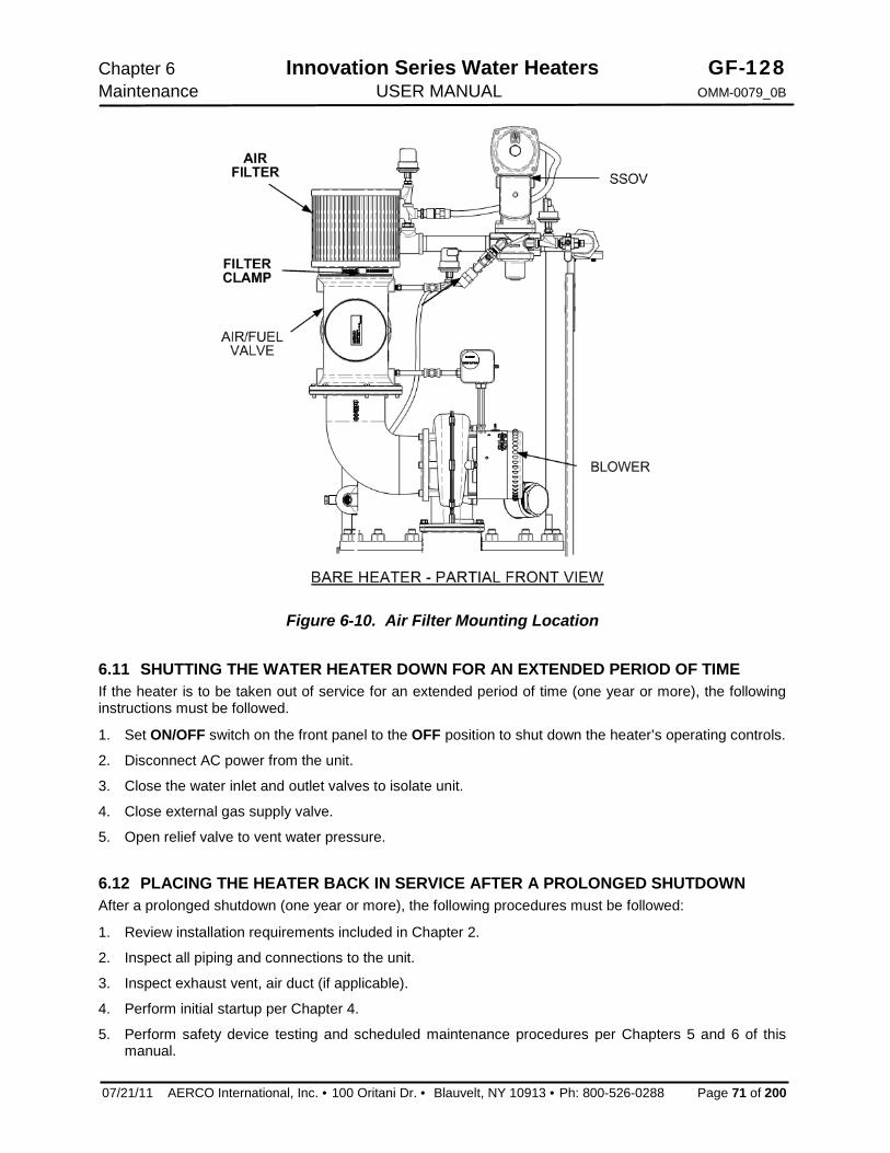
Chapter 6 Innovation Series Water Heaters GF-128 Maintenance USER MANUAL OMM-0079_0B
07/21/11 AERCO International, Inc. · 100 Oritani Dr. · Blauvelt, NY 10913 · Ph: 800-526-0288 Page 71 of 200
Figure 6-10. Air Filter Mounting Location 6.11 SHUTTING THE WATER HEATER DOWN FOR AN EXTENDED PERIOD OF TIME If the heater is to be taken out of service for an extended period of time (one year or more), the following instructions must be followed.
1. Set ON/OFF switch on the front panel to the OFF position to shut down the heater’s operating controls.
2. Disconnect AC power from the unit.
3. Close the water inlet and outlet valves to isolate unit.
4. Close external gas supply valve.
5. Open relief valve to vent water pressure. 6.12 PLACING THE HEATER BACK IN SERVICE AFTER A PROLONGED SHUTDOWN After a prolonged shutdown (one year or more), the following procedures must be followed:
1. Review installation requirements included in Chapter 2.
2. Inspect all piping and connections to the unit.
3. Inspect exhaust vent, air duct (if applicable).
4. Perform initial startup per Chapter 4.
5. Perform safety device testing and scheduled maintenance procedures per Chapters 5 and 6 of this manual.

GF-128 Innovation Series Water Heaters Chapter 7 OMM-0079_0B USER MANUAL Troubleshooting Guide
Page 72 of 200 AERCO International, Inc. · 100 Oritani Dr. · Blauvelt, NY 10913 · Ph.: 800-526-0288 07/21/11
This Page Is Intentionally Blank

Chapter 7 Innovation Series Water Heaters GF-128 Troubleshooting Guide USER MANUAL OMM-0079_0B
07/21/11 AERCO International, Inc. · 100 Oritani Dr. · Blauvelt, NY 10913 · Ph: 800-526-0288 Page 73 of 200
CHAPTER 7. TROUBLESHOOTING GUIDE 7.1 INTRODUCTION This troubleshooting guide is intended to aid service/maintenance personnel in isolating the cause of a fault in a Innovation Water Heater. The troubleshooting procedures contained herein are presented in tabular form on the following pages. These tables are comprised of three columns labeled: Fault Indication, Probable Cause and Corrective Action. The numbered items in the Probable Cause and Corrective Action columns correspond to each other. For example, Probable Cause No. 1 corresponds to Corrective Action No. 1, etc.
NOTE: The front panel of the C-More Control Box contains an RS232 port which can be interfaced to a laptop computer or other suitable device. This RS232 communication feature permits service personnel to view menu items and data logs which can be useful in isolating faults. Refer to Chapter 7 of this manual for detailed RS232 communication set-up and procedures.
When a fault occurs in the unit, proceed as follows to isolate and correct the fault:
1. Observe the fault messages displayed in the Control Box display.
2. Refer to the Fault Indication column in Troubleshooting Table 7-1 which follows and locate the Fault that best describes the existing conditions.
3. Proceed to the Probable Cause column and start with the first item (1) listed for the Fault Indication.
4. Perform the checks and procedures listed in the Corrective Action column for the first Probable Cause candidate.
5. Continue checking each additional Probable Cause for the existing fault until the fault is corrected.
6. Paragraph 7.2 and Table 7-2 contain additional troubleshooting information which may apply when no fault message is displayed.
If the fault cannot be corrected using the information provided in the Troubleshooting Tables, contact your local AERCO Representative.

GF-128 Innovation Series Water Heaters Chapter 7 OMM-0079_0B USER MANUAL Troubleshooting Guide
Page 74 of 200 AERCO International, Inc. · 100 Oritani Dr. · Blauvelt, NY 10913 · Ph.: 800-526-0288 07/21/11
This Page Is Intentionally Blank
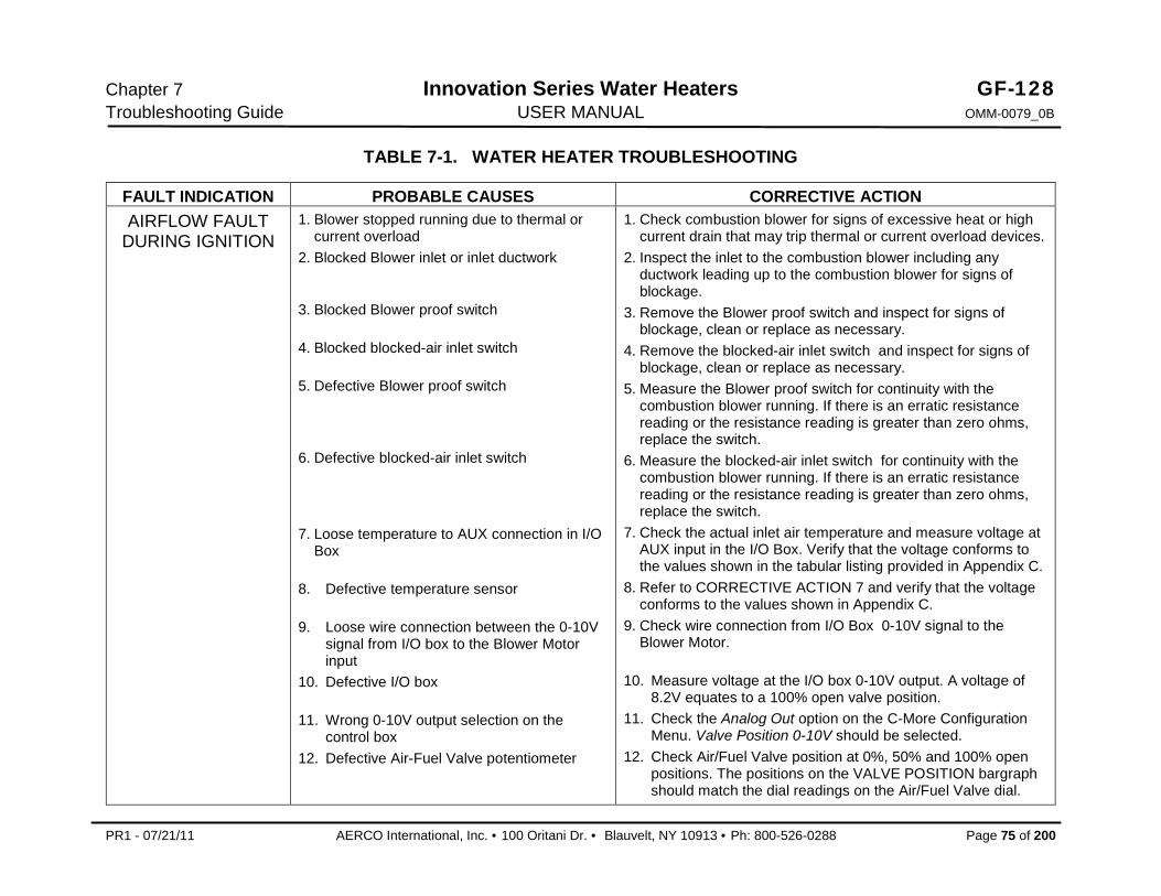
Chapter 7 Innovation Series Water Heaters GF-128 Troubleshooting Guide USER MANUAL OMM-0079_0B
PR1 - 07/21/11 AERCO International, Inc. · 100 Oritani Dr. · Blauvelt, NY 10913 · Ph: 800-526-0288 Page 75 of 200
TABLE 7-1. WATER HEATER TROUBLESHOOTING
FAULT INDICATION PROBABLE CAUSES CORRECTIVE ACTION AIRFLOW FAULT
DURING IGNITION 1. Blower stopped running due to thermal or
current overload 2. Blocked Blower inlet or inlet ductwork
3. Blocked Blower proof switch
4. Blocked blocked-air inlet switch
5. Defective Blower proof switch
6. Defective blocked-air inlet switch
7. Loose temperature to AUX connection in I/O Box
8. Defective temperature sensor
9. Loose wire connection between the 0-10V signal from I/O box to the Blower Motor input
10. Defective I/O box
11. Wrong 0-10V output selection on the control box
12. Defective Air-Fuel Valve potentiometer
1. Check combustion blower for signs of excessive heat or high current drain that may trip thermal or current overload devices.
2. Inspect the inlet to the combustion blower including any ductwork leading up to the combustion blower for signs of blockage.
3. Remove the Blower proof switch and inspect for signs of blockage, clean or replace as necessary.
4. Remove the blocked-air inlet switch and inspect for signs of blockage, clean or replace as necessary.
5. Measure the Blower proof switch for continuity with the combustion blower running. If there is an erratic resistance reading or the resistance reading is greater than zero ohms, replace the switch.
6. Measure the blocked-air inlet switch for continuity with the combustion blower running. If there is an erratic resistance reading or the resistance reading is greater than zero ohms, replace the switch.
7. Check the actual inlet air temperature and measure voltage at AUX input in the I/O Box. Verify that the voltage conforms to the values shown in the tabular listing provided in Appendix C.
8. Refer to CORRECTIVE ACTION 7 and verify that the voltage conforms to the values shown in Appendix C.
9. Check wire connection from I/O Box 0-10V signal to the Blower Motor.
10. Measure voltage at the I/O box 0-10V output. A voltage of 8.2V equates to a 100% open valve position.
11. Check the Analog Out option on the C-More Configuration Menu. Valve Position 0-10V should be selected.
12. Check Air/Fuel Valve position at 0%, 50% and 100% open positions. The positions on the VALVE POSITION bargraph should match the dial readings on the Air/Fuel Valve dial.

GF-128 Innovation Series Water Heaters Chapter 7 OMM-0079_0B USER MANUAL Troubleshooting Guide
Page 76 of 200 AERCO International, Inc. · 100 Oritani Dr. · Blauvelt, NY 10913 · Phone: 800-526-0288 PR1 - 07/21/11
TABLE 7-1. WATER HEATER TROUBLESHOOTING – Continued FAULT INDICATION PROBABLE CAUSES CORRECTIVE ACTION
AIRFLOW FAULT DURING PURGE
1. Blower not running or running too slow
2. Defective Air Flow Switch
3. Blocked Air flow Switch
4. Blocked Blower inlet or inlet ductwork.
5. No voltage to switch from control box.
6. PROBABLE CAUSES from 3 to 12 for AIRFLOW FAULT DURING IGNITION applies for this fault
1. Start the unit. If the blower does not run check the blower solid state relay for input and output voltage. If the relay is okay, check the blower.
2. Start the unit. If the blower runs, check the airflow switch for continuity. Replace the switch if there is no continuity.
3. Remove the air flow switch and inspect for signs of blockage, clean or replace as necessary.
4. Inspect the inlet to the combustion blower including any ductwork leading up to the combustion blower for signs of blockage.
5. Measure for 24 VAC during start sequence from each side of the switch to ground. If 24VAC is not present refer to qualified service personnel.
6. See CORRECTIVE ACTIONS from 3 to 12 for AIRFLOW FAULT DURING IGNITION.
AIRFLOW FAULT DURING RUN
1. Blower stopped running due to thermal or current overload
2. Blocked Blower inlet or inlet ductwork
3. Blocked airflow switch
4. Defective airflow switch
5. Combustion oscillations
6. PROBABLE CAUSES from 3 to 16 for AIRFLOW FAULT DURING IGNITION applies for this fault
1. Check combustion blower for signs of excessive heat or high current draw that may trip thermal or current overload devices.
2. Inspect the inlet to the combustion blower including any ductwork leading up to the combustion blower for signs of blockage.
3. Remove the airflow switch and inspect for signs of blockage, clean or replace as necessary.
4. Measure the airflow switch for continuity with the combustion blower running. If there is an erratic resistance reading or the resistance reading is greater than zero ohms, replace the switch.
5. Run unit to full fire. If the unit rumbles or runs rough, perform combustion calibration.
6. See CORRECTIVE ACTIONS from 3 to 16 for AIRFLOW FAULT DURING IGNITION.

Chapter 7 Innovation Series Water Heaters GF-128 Troubleshooting Guide USER MANUAL OMM-0079_0B
PR1 - 07/21/11 AERCO International, Inc. · 100 Oritani Dr. · Blauvelt, NY 10913 · Ph: 800-526-0288 Page 77 of 200
TABLE 7-1. WATER HEATER TROUBLESHOOTING – Continued
FAULT INDICATION PROBABLE CAUSES CORRECTIVE ACTION DELAYED
INTERLOCK OPEN 1. Delayed Interlock Jumper not
installed or removed. 2. Device proving switch hooked to
interlocks is not closed
1. Check for a jumper properly installed across the delayed interlock terminals in the I/O box.
2. If there are 2 external wires on these terminals, check to see if an end switch for a device such as a pump, louver, etc. is tied these interlocks. Ensure that the device and or its end switch are functional. (jumper may be temporarily installed to test interlock)
DIRECT DRIVE SIGNAL FAULT
1. Direct drive signal is not present: Not yet installed. Wrong polarity. Signal defective at source. Broken or loose wiring.
2. Signal is not isolated (floating). 3. Control Box signal type selection
switches not set for correct signal type (voltage or current).
1. Check I/O Box to ensure signal is hooked up. Hook up if not installed. If installed, check polarity. Measure signal level. Check continuity of wiring between source and unit.
2. Check signal at source to ensure it is isolated. 3. Check DIP switch on PMC board to ensure it is set correctly for
the type of signal being sent. Check control signal type set in Configuration Menu.
FLAME LOSS DURING IGN
1. Burner Ground Screw not installed or loose.
2. Worn flame detector
3. No spark from Spark Plug
4. Defective Ignition Transformer
5. Defective Ignition/Stepper (IGST) Board
6. Defective SSOV
1. Inspect and install/retighten Burner Ground Screw.
2. Remove and inspect the flame detector for signs of wear. Replace if necessary.
3. Close the internal gas valve in the unit. Install and arc a spark ignitor outside the unit.
4. If there is no spark, check for 120VAC at the primary side to the ignition transformer during the ignition cycle.
5. If 120VAC is not present, the IGST Board in the Control Box may be defective. Refer fault to qualified service personnel.
6. While externally arcing the spark ignitor, observe the open/close indicator in the Safety Shut-Off Valve to ensure it is opening. If the valve does not open, check for 120VAC at the valves input terminals. If 120VAC is not present, the IGST board in the Control Box may be defective. Refer fault to qualified service personnel.
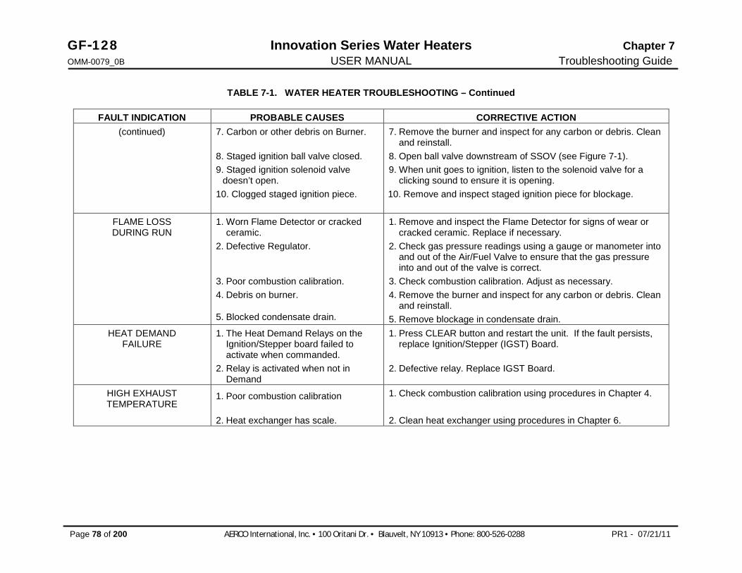
GF-128 Innovation Series Water Heaters Chapter 7 OMM-0079_0B USER MANUAL Troubleshooting Guide
Page 78 of 200 AERCO International, Inc. · 100 Oritani Dr. · Blauvelt, NY 10913 · Phone: 800-526-0288 PR1 - 07/21/11
TABLE 7-1. WATER HEATER TROUBLESHOOTING – Continued
FAULT INDICATION PROBABLE CAUSES CORRECTIVE ACTION (continued) 7. Carbon or other debris on Burner.
8. Staged ignition ball valve closed. 9. Staged ignition solenoid valve
doesn’t open. 10. Clogged staged ignition piece.
7. Remove the burner and inspect for any carbon or debris. Clean and reinstall.
8. Open ball valve downstream of SSOV (see Figure 7-1). 9. When unit goes to ignition, listen to the solenoid valve for a
clicking sound to ensure it is opening. 10. Remove and inspect staged ignition piece for blockage.
FLAME LOSS DURING RUN
1. Worn Flame Detector or cracked ceramic.
2. Defective Regulator.
3. Poor combustion calibration. 4. Debris on burner.
5. Blocked condensate drain.
1. Remove and inspect the Flame Detector for signs of wear or cracked ceramic. Replace if necessary.
2. Check gas pressure readings using a gauge or manometer into and out of the Air/Fuel Valve to ensure that the gas pressure into and out of the valve is correct.
3. Check combustion calibration. Adjust as necessary. 4. Remove the burner and inspect for any carbon or debris. Clean
and reinstall. 5. Remove blockage in condensate drain.
HEAT DEMAND FAILURE
1. The Heat Demand Relays on the Ignition/Stepper board failed to activate when commanded.
2. Relay is activated when not in Demand
1. Press CLEAR button and restart the unit. If the fault persists, replace Ignition/Stepper (IGST) Board.
2. Defective relay. Replace IGST Board.
HIGH EXHAUST TEMPERATURE
1. Poor combustion calibration
2. Heat exchanger has scale.
1. Check combustion calibration using procedures in Chapter 4.
2. Clean heat exchanger using procedures in Chapter 6.

Chapter 7 Innovation Series Water Heaters GF-128 Troubleshooting Guide USER MANUAL OMM-0079_0B
PR1 - 07/21/11 AERCO International, Inc. · 100 Oritani Dr. · Blauvelt, NY 10913 · Ph: 800-526-0288 Page 79 of 200
TABLE 7-1. WATER HEATER TROUBLESHOOTING – Continued
FAULT INDICATION PROBABLE CAUSES CORRECTIVE ACTION HIGH GAS
PRESSURE 1. Incorrect supply gas pressure.
2. Defective SSOV Actuator.
3. Defective High Gas Pressure Switch
1. Check to ensure gas pressure at inlet of SSOV is 2 psig maximum.
2. If gas supply pressure downstream of SSOV Actuator cannot be lowered, to 1.5” W.C. using the gas pressure adjustment screw (see para. 4.3, step 10), the SSOV Actuator may be defective.
3. Remove the leads from the high gas pressure switch and measure continuity across the common and normally closed terminals with the unit not firing. Replace the switch if it does not show continuity.
HIGH WATER TEMP SWITCH OPEN
1. Faulty Water temperature switch.
2. Incorrect PID settings.
3. Faulty shell temperature sensor.
4. Unit in Manual mode 5. Unit setpoint is greater than Over
Temperature Switch setpoint.
6. System flow rate changes are occurring faster than units can respond.
1. Test the temperature switch to insure it trips at its actual water temperature setting.
2. Check PID settings against Menu Default settings in the Appendix. If the settings have been changed, record the current readings then reset them to the default values.
3. Using the resistance charts in the Appendix C, Measure the resistance of Shell sensor and BTU sensor at a known water temperature.
4. If unit is in Manual Mode switch to Auto Mode. 5. Check setpoint of unit and setpoint of Temperature Switch;
Ensure that the temperature switch is set higher than the unit’s setpoint.
6. If the system is a variable flow system, monitor system flow changes to ensure that the rate of flow change is not faster than what the units can respond to.
HIGH WATER TEMPERATURE
1. See HIGH WATER TEMPERATURE SWITCH OPEN.
2. Temp HI Limit setting is too low.
1. See HIGH WATER TEMPERATURE SWITCH OPEN.
2. Check Temp HI Limit setting. IGN BOARD
COMM FAULT 1. Communication fault has occurred
between the PMC board and Ignition/Stepper (IGST) board
1. Press CLEAR button and restart unit. If fault persists, contact qualified Service Personnel.

GF-128 Innovation Series Water Heaters Chapter 7 OMM-0079_0B USER MANUAL Troubleshooting Guide
Page 80 of 200 AERCO International, Inc. · 100 Oritani Dr. · Blauvelt, NY 10913 · Phone: 800-526-0288 PR1 - 07/21/11
TABLE 7-1. WATER HEATER TROUBLESHOOTING – Continued
FAULT INDICATION PROBABLE CAUSES CORRECTIVE ACTION IGN SWTCH CLOSED
DURING PURGE 1. Air/Fuel Valve not rotating
2. Defective or shorted switch
3. Switch wired incorrectly
4. Defective Power Supply Board or fuse
5. Defective IGST Board
1. Start the unit. The Air/Fuel Valve should rotate to the purge (open) position. If the valve does not rotate at all or does not rotate fully open, check the Air/Fuel Valve calibration. If calibration is okay, the problem may be in the Air-Fuel Valve or the Control Box. Refer to qualified service personnel
2. . If the Air/Fuel Valve does rotate to purge, check the ignition switch for continuity between the N.O. and COM terminals. If the switch shows continuity when not in contact with the cam replace the switch.
3. Check to ensure that the switch is wired correctly (correct wire numbers on the normally open terminals). If the switch is wired correctly, replace the switch
4. Check DS1 & DS2 LEDs on Power Supply Board. If they are not steady ON, replace Power Supply Board.
5. Check “Heartbeat” LED DS1 and verify it is blinking ON & OFF every second. If not, replace IGST Board
IGN SWTCH OPEN DURING IGNITION
1. Air/Fuel Valve not rotating to ignition position.
2. Defective ignition switch
3. Defective Power Supply Board or fuse
4. Defective IGST Board
1. Start the unit. The Air/Fuel Valve should rotate to the purge (open) position, then back to ignition position (towards closed) during the ignition cycle. If the valve does not rotate back to the ignition position, check the Air/Fuel Valve calibration. If calibration is okay, the problem may be in the Air/Fuel Valve or the Control Box. Refer fault to qualified service personnel.
2. If the Air/Fuel Valve does rotate to the ignition position, check the ignition position switch for continuity between the N.O. and COM terminals when in contact with the cam.
3. Check DS1 & DS2 LEDs on Power Supply Board. If they are not steady ON, replace Power Supply Board.
4. Check “Heartbeat” LED DS1 and verify it is blinking ON & OFF every second. If not, replace IGST Board.

Chapter 7 Innovation Series Water Heaters GF-128 Troubleshooting Guide USER MANUAL OMM-0079_0B
PR1 - 07/21/11 AERCO International, Inc. · 100 Oritani Dr. · Blauvelt, NY 10913 · Ph: 800-526-0288 Page 81 of 200
TABLE 7-1. WATER HEATER TROUBLESHOOTING – Continued
FAULT INDICATION PROBABLE CAUSES CORRECTIVE ACTION INTERLOCK
OPEN 1. Interlock jumper not installed or
removed 2. Energy Management System does
not have unit enabled.
3. Device proving switch hooked to interlocks is not closed.
1. Check for a jumper properly installed across the interlock terminals in the I/O box.
2. If there are two external wires on these terminals check any Energy Management system to see if they have the units disabled (a jumper may be temporarily installed to see if the interlock circuit is functioning).
3. Check that proving switch for any device hooked to the interlock circuit is closing and that the device is operational.
LINE VOLTAGE OUT OF PHASE
1. Line and Neutral switched in AC Power Box.
2. Incorrect power supply transformer wiring.
1. Check hot and neutral in AC Power Box to ensure they are not reversed
2. Check transformer wiring, in AC Power Box, against the power box transformer wiring diagram to ensure it is wired correctly
LOW GAS PRESSURE
1. Incorrect supply gas pressure.
2. Defective Low Pressure Gas Switch
1. Measure gas pressure upstream of the SSOV Actuator(s) with the unit firing. For FM gas trains, ensure it is between 4.0” W.C. and 2 psig. For IRI gas trains, ensure it is between 4.2" W.C. and 2 psig (see para. 2.7.1).
2. Measure gas pressure at the low gas pressure switch. If it is greater than 2.6” W.C., measure continuity across the switch and replace if necessary.
LOW WATER LEVEL
1. Insufficient water level in system 2. Defective water level circuitry.
3. Defective water level probe.
1. Check system for sufficient water level. 2. Test water level circuitry using the Control Box front panel LOW
WATER TEST and RESET buttons. Replace water level circuitry if it does not respond.
3. Check continuity of probe end to the shell, change probe if there is no continuity.
MODBUS COMM FAULT
Unit not seeing information from Modbus network
Check network connections. If fault persists, contact qualified Service Personnel.
PRG SWTCH CLOSED DURING IGNITION
1. A/F Valve rotated open to purge and did not rotate to ignition position.
1. Start the unit. The Air/Fuel Valve should rotate to the purge (open) position, then back to ignition position (towards closed) during the ignition cycle. If the valve does not rotate back to the ignition position, check the Air/Fuel Valve calibration. If calibration is okay, the problem may be in the Air/Fuel Valve or the Control Box. Refer fault to qualified service personnel.

GF-128 Innovation Series Water Heaters Chapter 7 OMM-0079_0B USER MANUAL Troubleshooting Guide
Page 82 of 200 AERCO International, Inc. · 100 Oritani Dr. · Blauvelt, NY 10913 · Phone: 800-526-0288 PR1 - 07/21/11
TABLE 7-1. WATER HEATER TROUBLESHOOTING – Continued FAULT INDICATION PROBABLE CAUSES CORRECTIVE ACTION
(continued) 2. Defective or shorted switch.
3. Switch wired incorrectly. 4. Defective Power Supply Board or
fuse 5. Defective IGST Board
2. If the Air/Fuel Valve does rotate to the ignition position, check the purge switch for continuity between the N.O. and COM terminals. If the switch shows continuity when not in contact with the cam, check to ensure that the switch is wired correctly (correct wire numbers on the normally open terminals).
3. If the switch is wired correctly, replace the switch. 4. Check DS1 & DS2 LEDs on Power Supply Board. If they are not
steady ON, replace Power Supply Board. 5. Check “Heartbeat” LED DS1 and verify it is blinking ON & OFF
every second. If not, replace IGST Board. PRG SWTCH OPEN
DURING PURGE 1. Defective purge switch.
2. No voltage present at switch.
3. Switch wired incorrectly.
4. Defective Power Supply Board or
fuse 5. Defective IGST Board
1. If the air-fuel valve does rotate, check purge switch for continuity when closing. Replace switch if continuity does not exist.
2. Measure for 24 VAC from each side of the switch to ground. If 24VAC is not present, refer fault to qualified service personnel.
3. Check to ensure that the switch is wired correctly (correct wire numbers on the normally open terminals).
4. Check DS1 & DS2 LEDs on Power Supply Board. If they are not steady ON, replace Power Supply Board.
5. Check “Heartbeat” LED DS1 and verify it is blinking ON & OFF every second. If not, replace IGST Board.
OUTDOOR TEMP SENSOR FAULT
1. Loose or broken wiring. 2. Defective Sensor.
3. Incorrect Sensor.
1. Inspect Outdoor Temperature sensor for loose or broken wiring. 2. Check resistance of sensor to determine if it is within
specification. 3. Ensure that the correct sensor is installed.
RECIRC PUMP FAILURE 1. Internal recirculation pump failed. 1. Replace recirculation pump. REMOTE SETPT SIGNAL FAULT
1. Remote setpoint signal not present: Not yet installed. Wrong polarity. Signal defective at source. Broken or loose wiring.
2. Signal is not isolated (floating) if 4 to 20 mA.
3. Control Box signal type selection switches not set for correct signal type (voltage or current).
1. Check I/O Box to ensure signal is hooked up. Hook up if not installed. If installed, check polarity. Measure signal level. Check continuity of wiring between source and unit.
2. Check signal at source to ensure it is isolated.
3. Check DIP switch on PMC board to ensure it is set correctly for the type of signal being sent. Check control signal type set in Configuration Menu.
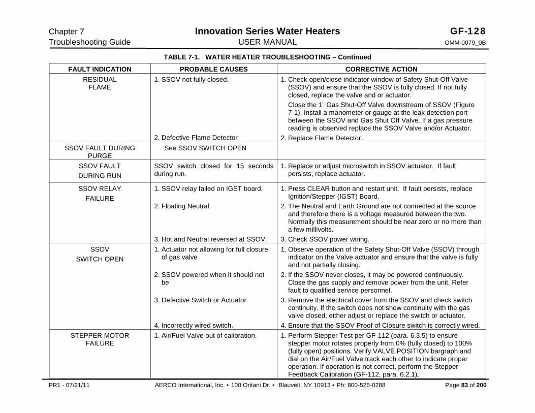
Chapter 7 Innovation Series Water Heaters GF-128 Troubleshooting Guide USER MANUAL OMM-0079_0B
PR1 - 07/21/11 AERCO International, Inc. · 100 Oritani Dr. · Blauvelt, NY 10913 · Ph: 800-526-0288 Page 83 of 200
TABLE 7-1. WATER HEATER TROUBLESHOOTING – Continued
FAULT INDICATION PROBABLE CAUSES CORRECTIVE ACTION RESIDUAL
FLAME 1. SSOV not fully closed.
2. Defective Flame Detector
1. Check open/close indicator window of Safety Shut-Off Valve (SSOV) and ensure that the SSOV is fully closed. If not fully closed, replace the valve and or actuator. Close the 1” Gas Shut-Off Valve downstream of SSOV (Figure 7-1). Install a manometer or gauge at the leak detection port between the SSOV and Gas Shut Off Valve. If a gas pressure reading is observed replace the SSOV Valve and/or Actuator.
2. Replace Flame Detector. SSOV FAULT DURING
PURGE See SSOV SWITCH OPEN
SSOV FAULT DURING RUN
SSOV switch closed for 15 seconds during run.
1. Replace or adjust microswitch in SSOV actuator. If fault persists, replace actuator.
SSOV RELAY FAILURE
1. SSOV relay failed on IGST board.
2. Floating Neutral.
3. Hot and Neutral reversed at SSOV.
1. Press CLEAR button and restart unit. If fault persists, replace Ignition/Stepper (IGST) Board.
2. The Neutral and Earth Ground are not connected at the source and therefore there is a voltage measured between the two. Normally this measurement should be near zero or no more than a few millivolts.
3. Check SSOV power wiring. SSOV
SWITCH OPEN 1. Actuator not allowing for full closure
of gas valve
2. SSOV powered when it should not be
3. Defective Switch or Actuator
4. Incorrectly wired switch.
1. Observe operation of the Safety Shut-Off Valve (SSOV) through indicator on the Valve actuator and ensure that the valve is fully and not partially closing.
2. If the SSOV never closes, it may be powered continuously. Close the gas supply and remove power from the unit. Refer fault to qualified service personnel.
3. Remove the electrical cover from the SSOV and check switch continuity. If the switch does not show continuity with the gas valve closed, either adjust or replace the switch or actuator.
4. Ensure that the SSOV Proof of Closure switch is correctly wired. STEPPER MOTOR
FAILURE 1. Air/Fuel Valve out of calibration.
1. Perform Stepper Test per GF-112 (para. 6.3.5) to ensure stepper motor rotates properly from 0% (fully closed) to 100% (fully open) positions. Verify VALVE POSITION bargraph and dial on the Air/Fuel Valve track each other to indicate proper operation. If operation is not correct, perform the Stepper Feedback Calibration (GF-112, para. 6.2.1).

GF-128 Innovation Series Water Heaters Chapter 7 OMM-0079_0B USER MANUAL Troubleshooting Guide
Page 84 of 200 AERCO International, Inc. · 100 Oritani Dr. · Blauvelt, NY 10913 · Phone: 800-526-0288 PR1 - 07/21/11
TABL 7-1. WATER HEATER TROUBLESHOOTING – Continued
FAULT INDICATION PROBABLE CAUSES CORRECTIVE ACTION (continued) 2. Air/Fuel Valve unplugged.
3. Loose wiring connection to the stepper motor.
4. Defective Air/Fuel Valve stepper motor.
5. Defective Power Supply Board or fuse
6. Defective IGST Board
2. Check that the Air/Fuel Valve is connected to the Control Box. 3. .Inspect for loose connections between the Air/Fuel Valve motor
and the wiring harness. 4. Replace stepper motor.
5. Check DS1 & DS2 LEDs on Power Supply Board. If they are not
steady ON, replace Power Supply Board. 6. Check “Heartbeat” LED DS1 and verify it is blinking ON & OFF
every second. If not, replace IGST Board. 7.2 ADDITIONAL FAULTS WITHOUT SPECIFIC FAULT MESSAGES Refer to Table 7-2 to troubleshoot faults which may occur without a specific fault message being displayed.
TABLE 7-2. WATER HEATER TROUBLESHOOTING WITH NO FAULT MESSAGE DISPLAYED OBSERVED INCIDENT PROBABLE CAUSES CORRECTIVE ACTION
Hard Light-Off 1. Staged Ignition Ball Valve closed.
2. Clogged/damaged Gas Injector on Igniter-Injector (Figure 7-2).
3. Defective Staged Ignition Solenoid (Figure 7-2)
1. Open the 1/4” Staged Ignition Ball Valve on the downstream side of the SSOV (Figure 7-1).
2. Disconnect the Staged Ignition Assembly from the Igniter-Injector and inspect Gas Injector to ensure it is not clogged or damaged.
3. Close the 1” Manual Shutoff Valve and the 1/4” Ball Valve that connects to the flex hose of the Staged Ignition Assy. (Figure 7-1). Attempt to start the unit and listen for a “clicking” sound that the Staged Ignition Solenoid makes during Ignition Trial. If “clicking” sound is not heard after 2 or 3 attempts, replace the Staged Ignition Solenoid.
Fluctuating Gas Pressure 1. Gas pressure going into unit is fluctuating.
2. Damping Orifice not installed.
1. Stabilize gas pressure going into unit. If necessary, troubleshoot Building Supply Regulator.
2. Check to ensure that the Damping Orifice is installed in the SSOV Actuator shown in Figure 7-3. (For IRI Gas Trains, the Damping Orifice is installed in the downstream SSOV Actuator).
Air/Fuel Valve “hunting” at the 80% Valve Position
1. IGST and Power Supply Boards in Control Box are outdated.
1. Check to ensure that the IGST and Power Supply Boards are Rev. E or higher.

Chapter 7 Innovation Series Water Heaters GF-128 Troubleshooting Guide USER MANUAL OMM-0079_0B
07/21/11 AERCO International, Inc. · 100 Oritani Dr. · Blauvelt, NY 10913 · Ph: 800-526-0288 Page 85 of 200
Figure 7-1. Gas Train Component Locations
Figure 7-2. Blower-Side Intake Manifold (Shown removed from Heater)

GF-128 Innovation Series Water Heaters Chapter 7 OMM-0079_0B USER MANUAL Troubleshooting Guide
Page 86 of 200 AERCO International, Inc. · 100 Oritani Dr. · Blauvelt, NY 10913 · Ph.: 800-526-0288 07/21/11
Figure 7-3. SSOV Actuator With Gas Pressure Adjustment & Damping Orifice
Chapter 8 Innovation Series Water Heaters GF-128 RS232 Communication USER MANUAL OMM-0079_0B
07/21/11 AERCO International, Inc. · 100 Oritani Dr. · Blauvelt, NY 10913 · Ph: 800-526-0288 Page 87 of 200
CHAPTER 8. RS232 COMMUNICATION 8.1 INTRODUCTION The RS232 port on the front panel of the C-More Control Box (Figure 3-1) can be interfaced to a laptop computer or other suitable terminal using a RS232 adapter cable. RS232 communication can be accomplished using any “Dumb Terminal” emulation, such as “Hyper Terminal” which is included with Microsoft Windows. The RS232 communication feature permits viewing or changing of Control Panel menu options and also provides access to data logs showing Event Time Line, Fault and Sensor log displays.
8.2 RS232 COMMUNICATION SETUP Regardless of the terminal emulation utilized, the following guidelines must be adhered to when setting up the RS232 communication link:
· Baud Rate – The baud rates which can be used with the C-More Control Panel are: · 2400 · 4800 · 9600 (Default) · 19.2K · Data Format – The program must be set for: 8 data bits, 1 stop bit, no parity and either
Xon/Xoff or No flow control. 8.3 MENU PROCESSING UTILIZING RS232 COMMUNICATION Viewing data logs and viewing or changing Control Panel menu options using RS232 communication is accomplished as follows:
1. Start the emulator software program and ensure that the specified baud rate and data formats have been entered.
2. Press the Enter key on the laptop. An asterisk (*) prompt should appear.
3. At the prompt, enter the valid RS232 password (jaguar) in lower case letters and press Enter.
4. “Welcome to Aerco” will appear in the laptop or “dumb terminal” display with a listing of the following available entry choices:
M = Display next Menu D = Display menu items N = Display next menu items Cxx = Change item xx F = Fault log display S = Sensor log display T = Time line display L = Log off

GF-128 Innovation Series Water Heaters Chapter 8 OMM-0079_0B USER MANUAL RS232 Communication
Page 88 of 200 AERCO International, Inc. · 100 Oritani Dr. · Blauvelt, NY 10913 · Ph.: 800-526-0288 07/21/11
NOTE The Level 1 password (159) must be entered to change options in the Setup, Configuration and Tuning Menus. The Level 2 password (6817) must be entered to view or change options in the Calibration and Diagnostics Menus. With the exception of the password entry, all other keyboard entries can be made using either upper or lower case.
5. To view the available menus in the top-down sequence shown in Figure 3-2, enter M <Rtn>. The Menu title and first 10 options will be displayed.
6. When viewing menus containing more than 10 options, enter N <Rtn> to display the remaining options.
7. Shortcut keys are also available to go directly to a specific menu. These shortcut keys are: m0 Default (Operating) Menu m1 Setup Menu m2 Configuration Menu m3 Tuning Menu m4 Calibration Menu m5 Diagnostic Menu
8. To change a value or setting for a displayed menu option, proceed as follows: (d) Enter C, followed by the number to the right of the displayed option to be changed, and then
press <Rtn>.
Enter the desired value or setting for the option and press <Rtn>. Refer to Chapter 3, Tables 3-2 through 3-5 for allowable entry ranges and settings for the Operating, Setup, Configuration and Tuning Menus. (The Calibration and Diagnostic Menus should only be used by Factory-Trained service personnel).
Menu changes will be stored in non-volatile memory.
9. To redisplay the menu and view the option which was just changed in step 5, enter D and press <Rtn>.
10. To display the Fault (F) Log, Sensor (S) Log or Time (T) Line Log, press F, S or T followed by <Rtn>. Refer to paragraph 9.4 for descriptions and samples of these data logs.
11. To log off and terminate the RS232 com-munication link, press L followed by <Rtn>. 8.4 DATA LOGGING During operation, the C-More Control Panel continuously monitors and logs data associated with operational events, faults and sensor readings associated with the water heater system. Descriptions of these data logs are provided in the following paragraphs. The basic procedure for accessing each data log is described in paragraph 9.3, step 7.
8.4.1 Fault Log The C-More Control Panel logs the last 10 faults (0 – 9) starting with the most recent (#0). They can be viewed in the front panel display or via the RS232 port. The Fault Log cannot be cleared. If the Fault Log already contains 10 faults, the earliest fault is overwritten when a new fault occurs. A sample Fault Log display is shown in Table 8-1.

Chapter 8 Innovation Series Water Heaters GF-128 RS232 Communication USER MANUAL OMM-0079_0B
07/21/11 AERCO International, Inc. · 100 Oritani Dr. · Blauvelt, NY 10913 · Ph: 800-526-0288 Page 89 of 200
NOTE The Operation Time (T) Log can store thousands of records. Therefore, to view the most recently logged record, enter “T” followed by 0 (zero) and press Enter (i.e. T0 <Enter>). To view earlier records in reverse chronological order, enter T and press Enter. To go back 200 or 1000 records, enter T200 or T1000, etc. and press Enter.
8.4.2 Operation Time Log The Operation Time Log consists of a string of ASCII records stored in non-volatile memory within the C-More Control Panel. Events such as power-up, ignition and turn-off are time stamped. Data logged while the unit is running are run-length encoded. Data is logged or the run-length incremented every 30 seconds. For a new run record to be logged, the fire rate or flame strength must change by more than 5%, or the run mode must change. At steady-state, the run-length is allowed to reach a maximum of 30 minutes before the record is logged. This means that no more than 30 minutes of data can be lost if the unit loses power. Table 8-2 shows a sample Operation Time Log for a unit:
The Operation Time Log can only be accessed through the RS232 interface using a laptop or other terminal device. Ten operation time records are displayed for each T command entry. The operation time log can be cleared ONLY by factory authorized personnel using the Clear Log option in the Factory menu.
NOTE The Sensor (S) Log can store up to 1200 records. Therefore, to view the most recently logged record, enter “S” followed by 0 (zero) and then press Enter (i.e. S0 <Enter>). To view earlier records in reverse chronological order, enter S and press Enter. To go back 200 or 700 records, enter S200 or S700, etc. and press Enter.
8.4.3 Sensor Log The sensor values can be logged at a different rate if needed by setting the Sensor Log Interval in the Diagnostics Menu. The log interval can vary from once every minute to once every day. Table 8-3 shows a sample Sensor Log every 5 minutes for a heater running in Constant Setpoint mode.
Table 8-1. Sample Fault Log Display
No. Fault Message Cycle Date Time 0 Direct Drive Signal Fault 609 1/10/02 8:42am 1 Low Gas Pressure 366 7/04/01 5:29pm 2 Loss of Power 0 1/01/01 11:50am
Table 8-2. Sample Operation Time Log Display
Status Fire Rate Flame Run Length Date Time Off, Direct Drive 0 0 8 1/15/02 2:35pm Run, Direct Drive 38 100 34 1/15/02 2:27pm Run, Direct Drive 31 100 30 1/15/02 1:53am Run, Direct Drive 35 100 2 1/15/02 1:23pm Run, Direct Drive 29 100 0 1/15/02 1:21pm Ignition 0 0 0 1/15/02 1:20pm Off, Switch 0 0 35 1/15/02 12:30pm Run, Manual 40 100 0 1/15/02 11:55am Ignition 0 0 0 1/15/02 11:55am Power-up 0 0 0 1/15/02 11:50am

GF-128 Innovation Series Water Heaters Chapter 8 OMM-0079_0B USER MANUAL RS232 Communication
Page 90 of 200 AERCO International, Inc. · 100 Oritani Dr. · Blauvelt, NY 10913 · Ph.: 800-526-0288 07/21/11
Table 8-3. Sample Sensor Log Display Setpt Outlet Outdr FFWD Aux Inlet Exhst CO O2 Flow Date Time 130 181 OPEN OPEN OPEN OPEN OPEN 0 .0 0 1/15/02 5:51pm 130 180 OPEN OPEN OPEN OPEN OPEN 0 .0 0 1/15/02 5:46pm 130 180 OPEN OPEN OPEN OPEN OPEN 0 .0 0 1/15/02 5:41pm 130 179 OPEN OPEN OPEN OPEN OPEN 0 .0 0 1/15/02 5:36pm 130 180 OPEN OPEN OPEN OPEN OPEN 0 .0 0 1/15/02 5:31pm 130 180 OPEN OPEN OPEN OPEN OPEN 0 .0 0 1/15/02 5:26pm 130 180 OPEN OPEN OPEN OPEN OPEN 0 .0 0 1/15/02 5:21pm 130 180 OPEN OPEN OPEN OPEN OPEN 0 .0 0 1/15/02 5:16pm 130 179 OPEN OPEN OPEN OPEN OPEN 0 .0 0 1/15/02 5:11pm 130 180 OPEN OPEN OPEN OPEN OPEN 0 .0 0 1/15/02 5:06pm
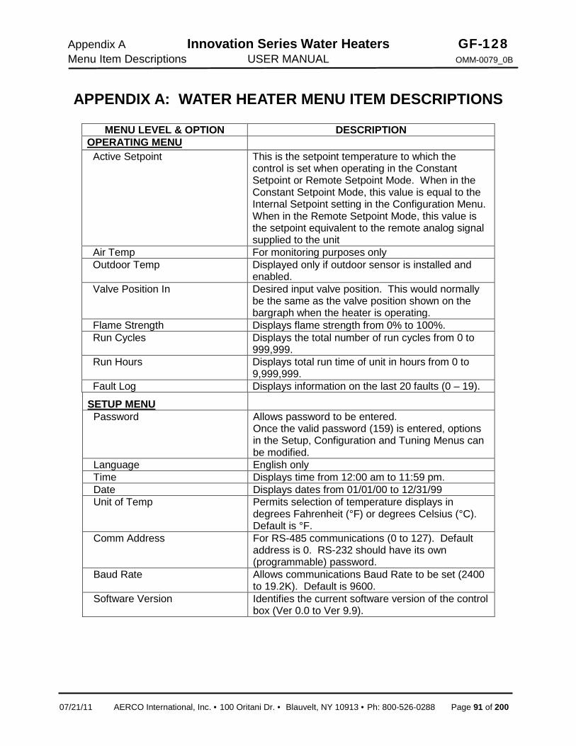
Appendix A Innovation Series Water Heaters GF-128 Menu Item Descriptions USER MANUAL OMM-0079_0B
07/21/11 AERCO International, Inc. · 100 Oritani Dr. · Blauvelt, NY 10913 · Ph: 800-526-0288 Page 91 of 200
APPENDIX A: WATER HEATER MENU ITEM DESCRIPTIONS
MENU LEVEL & OPTION DESCRIPTION OPERATING MENU Active Setpoint This is the setpoint temperature to which the
control is set when operating in the Constant Setpoint or Remote Setpoint Mode. When in the Constant Setpoint Mode, this value is equal to the Internal Setpoint setting in the Configuration Menu. When in the Remote Setpoint Mode, this value is the setpoint equivalent to the remote analog signal supplied to the unit
Air Temp For monitoring purposes only Outdoor Temp Displayed only if outdoor sensor is installed and
enabled. Valve Position In Desired input valve position. This would normally
be the same as the valve position shown on the bargraph when the heater is operating.
Flame Strength Displays flame strength from 0% to 100%. Run Cycles Displays the total number of run cycles from 0 to
999,999. Run Hours Displays total run time of unit in hours from 0 to
9,999,999. Fault Log Displays information on the last 20 faults (0 – 19). SETUP MENU Password Allows password to be entered.
Once the valid password (159) is entered, options in the Setup, Configuration and Tuning Menus can be modified.
Language English only Time Displays time from 12:00 am to 11:59 pm. Date Displays dates from 01/01/00 to 12/31/99 Unit of Temp Permits selection of temperature displays in
degrees Fahrenheit (°F) or degrees Celsius (°C). Default is °F.
Comm Address For RS-485 communications (0 to 127). Default address is 0. RS-232 should have its own (programmable) password.
Baud Rate Allows communications Baud Rate to be set (2400 to 19.2K). Default is 9600.
Software Version Identifies the current software version of the control box (Ver 0.0 to Ver 9.9).

GF-128 Innovation Series Water Heaters Appendix A OMM-0079_0B USER MANUAL Menu Item Descriptions
Page 92 of 200 AERCO International, Inc. · 100 Oritani Dr. · Blauvelt, NY 10913 · Phone: 800-526-0288 07/21/11
WATER HEATER MENU ITEM DESCRIPTIONS – Continued
MENU LEVEL & OPTION DESCRIPTION CONFIGURATION MENU Internal Setpoint Allows internal setpoint to be set . Default is 130°F. Unit Type Allows selection of KC Boiler, KC Boiler LN, BMK
Boiler, BMK Boiler LN, BMK Boiler Dual, KC Water Heater, KC Water Heater LN, Water Heater 2010
Unit Size Sets unit size from 0.5 to 6.0 MBTUs. Default is 1.0 MBTU.
Fuel Type Allows selection of Natural Gas or Propane. Default is Natural Gas.
Heater Mode It allows selection of: Constant Setpoint, or Remote Setpoint. Default is Constant Setpoint Mode.
Remote Signal Used to set the type of external signal which will be used when operating in the Remote Setpoint Mode. The factory default is 4-20 mA/1-5V.
Outdoor Sensor Allows outdoor sensor function to be enabled or disabled. Default is disabled.
Setpoint Lo Limit Used to set the minimum allowable setpoint (40°F to Setpoint Hi Limit). Default is 60°F
Setpoint Hi Limit Used to set the maximum allowable setpoint (Setpoint Lo Limit to 240°F). Default is 200°F.
Temp Hi Limit This is the maximum allowable outlet temperature (40 to 240°F). Any temperature above this setting will turn off the unit. The temperature must then drop 5°F below this setting to allow the unit to run. Default Hi Limit is 160°F.
Max Valve Position Sets the maximum allowable valve position for the unit (40% to 100%). Default is 100%.
Pump Delay Timer Specifies the amount of time (0 to 30 min.) to keep the pump running after the unit turns off. Default is zero.
Aux Start On Dly Specifies the amount of time to wait (0 to 120 sec.) between activating the Aux Relay (due to a demand) and checking the pre-purge string to start the heater. Default is 0 sec.
Failsafe Mode Allows the Failsafe mode to be set to either Constant Setpoint or Shutdown. Default is Shutdown.
Analog Output Must be set to Valve Pos 0-10V. Lo Fire Timer Specifies how long (2 to 600 sec.) to remain in the
low fire position after ignition, before going to the desired output. Default is 2 sec.
Network Timeout Specifies the timeout value (seconds) before a Modbus fault is declared. Available settings range from 5 to 999 seconds. Default is 30 seconds.

Appendix A Innovation Series Water Heaters GF-128 Menu Item Descriptions USER MANUAL OMM-0079_0B
07/21/11 AERCO International, Inc. · 100 Oritani Dr. · Blauvelt, NY 10913 · Ph: 800-526-0288 Page 93 of 200
WATER HEATER MENU ITEM DESCRIPTIONS - Continued
MENU LEVEL & OPTION DESCRIPTION CONFIGURATION MENU (Cont.) HI DB Setpt EN Operating at a Valve Position below this value will
inhibit the DEADBAND feature. When operating at a Valve Position below this value, the effective Setpoint is equal to Active Setpoint + DEADBAND HIGH. Setting range is from 0 to 100. (Default is 30)
Demand Offset This entry will reduce excessive ON/OFF cycling in AUTO mode. When this entry is a non-zero value, the unit will not turn on again until Valve Position In reaches the Start Level value AND the Outlet Temperature goes below the Active Setpoint – Demand Offset. In addition, the heater will fire at the 29% Valve Position level or below for a period of one minute. When this entry is set to zero, the unit will turn on again as soon as the Valve Position in reaches the Start Level value. There will not be a one minute delay when firing at the 29% Valve Position level. Setting range is 0 to 25. (Default is 0)
Deadband High Deadband Low
Deadband High and Deadband Low settings create an “Outlet Temperature” Zone. In which no Valve Position corrections will be attempted. The Deadband ZONE is defined as operating with an Outlet Temperature between Active Setpoint + Deadband High and Active Setpoint – Deadband Low. When the Outlet Temperature reaches Active Setpoint and remains there for a period of 15 seconds, the unit will go into a DEADBAND MODE at which point no Valve Position corrections will be attempted while the Outlet Temperature remains anywhere within the Deadband ZONE. When the unit is in the DEADBAND MODE, the °F or °C LED will flash on and off. When the Outlet Temperature drifts out of the Deadband ZONE, the DEADBAND MODE will be terminated and the PID LOOP will again attempt Valve Position corrections. Setting range is 0 to 25. (Default is 0 for both Deadband High and Deadband Low)

GF-128 Innovation Series Water Heaters Appendix A OMM-0079_0B USER MANUAL Menu Item Descriptions
Page 94 of 200 AERCO International, Inc. · 100 Oritani Dr. · Blauvelt, NY 10913 · Phone: 800-526-0288 07/21/11
WATER HEATER MENU ITEM DESCRIPTIONS - Continued
MENU LEVEL & OPTION DESCRIPTION TUNING MENU Prop Band Generates a valve position based on the error that
exists between the setpoint temperature and the actual outlet temperature. If the actual error is less than the proportional band setting (1 to 120°F), the valve position will be less than 100%. If the error is equal to or greater than the proportional band setting, the valve position will be 8%.
Integral Gain This sets the fraction of the output, due to setpoint error, to add or subtract from the output each minute to move towards the setpoint. Gain is adjustable from 0.00 to 1.00 (Default is 1.6).
Derivative Time This value (0.0 to 20.0 min.) responds to the rate of change of the setpoint error. This is the time that this action advances the output.
Min Load Adj Setting is adjustable from -50°F to +50°F (Default is zero). It adjusts the output by adding an offset to the breakpoint chart at minimum flow. This is used to fine tune Feed-Forward (FFWD) output at low flow levels.
Max Load Adj Setting is adjustable from -50°F to +50°F (Default is zero). It adjusts the output by changing the scaling of the breakpoint chart at maximum flow.
FFWD Temp Displays the Feed-Forward temperature. Outlet Feedback Used to Enable or Disable feedback. Disable this
function for Feed-Forward control only. Feedback Gain* Adjustable from 0.01 to 1.00 (Default is 0.05). Breakpoint at 100% Thru Breakpoint at 0%
Allows breakpoint temperature settings (30°F to 240°F) to be entered for 100% to 0% in 10% increments. See Appendix D for default values.
Reset Defaults? Allows Tuning Menu options to be reset to their Factory Default values.
*Only displayed when Heater Tuning Display is enabled by factory authorized personnel.

Appendix B Innovation Series Water Heaters GF-128 Display Messages USER MANUAL OMM-0079_0B
07/21/11 AERCO International, Inc. · 100 Oritani Dr. · Blauvelt, NY 10913 · Ph: 800-526-0288 Page 95 of 200
APPENDIX B: STARTUP, STATUS AND FAULT MESSAGES
TABLE B-1. STARTUP AND STATUS MESSAGES
MESSAGE DESCRIPTION DEMAND DELAY
XX sec Displayed if Demand Delay is active.
DISABLED HH:MM pm, pm
MM/DD/YY
Displayed if ON/OFF switch is set to OFF. The display also shows the time (am or pm) and date that the unit was disabled.
FLAME PROVEN
Displayed after flame has been detected for a period of 2 seconds. Initially, the flame strength is shown in %. After 5 seconds has elapsed, the time and date are shown in place of flame strength.
IGNITION TRIAL XX sec
Displayed during ignition trial of startup sequence. The duration of cycle counts up in seconds.
PURGING XX sec
Displayed during the purge cycle during startup. The duration of the purge cycle counts up in seconds.
STANDBY Displayed when ON/OFF switch is in the ON position, but there is no demand for heat. The time and date are also displayed.
WAIT Prompts the operator to wait. WARMUP
XX sec Displayed for 2 minutes during the initial warm-up only.

GF-128 Innovation Series Water Heaters Appendix B OMM-0079_0B USER MANUAL Display Messages
Page 96 of 200 AERCO International, Inc. · 100 Oritani Dr. · Blauvelt, NY 10913 · Phone: 800-526-0288 07/21/11
TABLE B-2. FAULT MESSAGES
FAULT MESSAGE FAULT DESCRIPTION
AIRFLOW FAULT DURING PURGE
The Blower Proof Switch opened during purge, or air inlet is blocked.
AIRFLOW FAULT DURING IGN
The Blower Proof Switch opened during ignition.
AIRFLOW FAULT DURING RUN
The Blower Proof Switch opened during run.
DELAYED INTERLOCK OPEN
The Delayed Interlock is open.
DIRECT DRIVE SIGNAL FAULT
The direct drive signal is not present or is out of range.
FFWD TEMP SENSOR FAULT
The temperature measured by the Feed Forward (FFWD) Sensor is out of range.
FLAME LOSS DURING IGN
The Flame signal was not seen during ignition or lost within 5 seconds after ignition.
FLAME LOSS DURING RUN
The Flame signal was lost during run.
HEAT DEMAND FAILURE
The Heat Demand Relays on the Ignition board failed to activate when commanded.
HIGH EXHAUST TEMPERATURE
The High Exhaust Temperature Limit Switch is closed.
HIGH GAS PRESSURE
The High Gas Pressure Limit Switch is open.
HIGH WATER TEMPERATURE
The temperature measured by the Outlet Sensor exceeded the Temp Hi Limit setting.
HIGH WATER TEMP SWITCH OPEN
The High Water Temperature Limit Switch is open.
IGN BOARD COMM FAULT
A communication fault has occurred between the PMC board and Ignition board.
IGN SWTCH CLOSED DURING PURGE
The Ignition Position Limit switch on the Air/Fuel Valve closed during purge.
IGN SWTCH OPEN DURING IGNITION
The Ignition Position Limit switch on the Air/Fuel Valve opened during ignition.
INTERLOCK OPEN
The Remote Interlock is open.
LINE VOLTAGE OUT OF PHASE
The Line (Hot) and Neutral wires are reversed.
LOW GAS PRESSURE
The Low Gas Pressure Limit Switch is open.
LOW WATER LEVEL
The Low Water Cutoff board is indicating low water level.
NETWORK COMM FAULT
The RS-485 network information is not present or is corrupted.
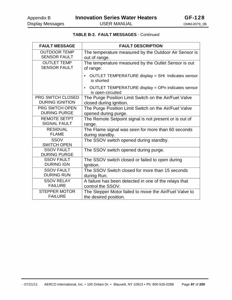
Appendix B Innovation Series Water Heaters GF-128 Display Messages USER MANUAL OMM-0079_0B
- 07/21/11 AERCO International, Inc. · 100 Oritani Dr. · Blauvelt, NY 10913 · Ph: 800-526-0288 Page 97 of 200
TABLE B-2. FAULT MESSAGES - Continued
FAULT MESSAGE FAULT DESCRIPTION OUTDOOR TEMP SENSOR FAULT
The temperature measured by the Outdoor Air Sensor is out of range.
OUTLET TEMP SENSOR FAULT
The temperature measured by the Outlet Sensor is out of range: · OUTLET TEMPERATURE display = SHt Indicates sensor
is shorted
· OUTLET TEMPERATURE display = OPn indicates sensor is open-circuited
PRG SWTCH CLOSED DURING IGNITION
The Purge Position Limit Switch on the Air/Fuel Valve closed during ignition.
PRG SWTCH OPEN DURING PURGE
The Purge Position Limit Switch on the Air/Fuel Valve opened during purge.
REMOTE SETPT SIGNAL FAULT
The Remote Setpoint signal is not present or is out of range.
RESIDUAL FLAME
The Flame signal was seen for more than 60 seconds during standby.
SSOV SWITCH OPEN
The SSOV switch opened during standby.
SSOV FAULT DURING PURGE
The SSOV switch opened during purge.
SSOV FAULT DURING IGN
The SSOV switch closed or failed to open during ignition.
SSOV FAULT DURING RUN
The SSOV Switch closed for more than 15 seconds during Run.
SSOV RELAY FAILURE
A failure has been detected in one of the relays that control the SSOV.
STEPPER MOTOR FAILURE
The Stepper Motor failed to move the Air/Fuel Valve to the desired position.

GF-128 Innovation Series Water Heaters Appendix B OMM-0079_0B USER MANUAL Display Messages
Page 98 of 200 AERCO International, Inc. · 100 Oritani Dr. · Blauvelt, NY 10913 · Phone: 800-526-0288 07/21/11
This Page Is Intentionally Blank
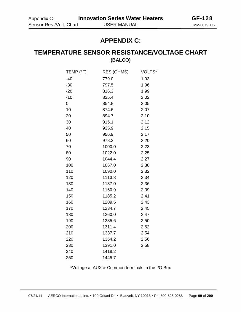
Appendix C Innovation Series Water Heaters GF-128 Sensor Res./Volt. Chart USER MANUAL OMM-0079_0B
07/21/11 AERCO International, Inc. · 100 Oritani Dr. · Blauvelt, NY 10913 · Ph: 800-526-0288 Page 99 of 200
APPENDIX C:
TEMPERATURE SENSOR RESISTANCE/VOLTAGE CHART (BALCO)
TEMP (°F) RES (OHMS) VOLTS* -40 -30 -20 -10 0 10 20 30 40 50 60 70 80 90 100 110 120 130 140 150 160 170 180 190 200 210 220 230 240 250
779.0 797.5 816.3 835.4 854.8 874.6 894.7 915.1 935.9 956.9 978.3 1000.0 1022.0 1044.4 1067.0 1090.0 1113.3 1137.0 1160.9 1185.2 1209.5 1234.7 1260.0 1285.6 1311.4 1337.7 1364.2 1391.0 1418.2 1445.7
1.93 1.96 1.99 2.02 2.05 2.07 2.10 2.12 2.15 2.17 2.20 2.23 2.25 2.27 2.30 2.32 2.34 2.36 2.39 2.41 2.43 2.45 2.47 2.50 2.52 2.54 2.56 2.58
*Voltage at AUX & Common terminals in the I/O Box

GF-128 Innovation Series Water Heaters Appendix C OMM-0079_0B USER MANUAL Sensor Res./Volt. Chart
Page 100 of 200 AERCO International, Inc. · 100 Oritani Dr. · Blauvelt, NY 10913 · Phone: 800-526-0288 06/10/11
This Page Is Intentionally Blank

Appendix D Innovation Series Water Heaters GF-128 Default Settings USER MANUAL OMM-0079_0B
07/21/11 AERCO International, Inc. · 100 Oritani Dr. · Blauvelt, NY 10913 · Ph: 800-526-0288 Page 101 of 200
APPENDIX D: WATER HEATER DEFAULT SETTINGS MENU & OPTION FACTORY DEFAULT
Setup Menu
Password 0
Language English
Unit of Temp Fahrenheit
Comm Address 0
Baud Rate 9600
Configuration Menu
Internal Setpt 130°F
Unit Type Innovation WH
Unit Size 600, 800, 1060 MBH
Fuel Type Natural Gas
Heater Mode Constant Setpoint
Remote Signal (If Heater Mode = Remote Setpoint)
4 – 20 mA ,/ 1-5V
Outdoor Sensor Disabled
Setpt Lo Limit 60°F
Setpt Hi Limit 200°F
Temp Hi Limit 160°F
Max Valve Position 100%
Aux Start On Dly 0 sec
Failsafe Mode Shutdown
mA Output Off
Lo Fire Timer 2 sec.
Setpt Limiting Disabled
Setpt Limit Band 0°F
Network Timeout 30 seconds
HI DB Setpt En 30
Demand Offset 0
Deadband High 0
Deadband Low 0

GF-128 Innovation Series Water Heaters Appendix D OMM-0079_0B USER MANUAL Default Settings
Page 102 of 200 AERCO International, Inc. · 100 Oritani Dr. · Blauvelt, NY 10913 · Phone: 800-526-0288 07/21/11
WATER HEATER DEFAULT SETTINGS - Continued
MENU & OPTION FACTORY DEFAULT
Tuning Menu
Prop Band 8°F
Integral Gain 1.60
Derivative Time 0.10 min
Min Load Adj 0°F
Max Load Adj 0°F
FFWD Temp N/A
Outlet Feedback On
Feedback Gain 0.05
Breakpoint At 100% 83°F
Breakpoint At 90% 84°F
Breakpoint At 80% 85°F
Breakpoint At 70% 86°F
Breakpoint At 60% 87°F
Breakpoint At 50% 88°F
Breakpoint At 40% 92°F
Breakpoint At 30% 105°F
Breakpoint At 20% 124°F
Breakpoint At 10% 136°F
Breakpoint At 0% 138°F
Reset Defaults? No

Appendix E Innovation Series Water Heaters GF-128 Parts Lists Drawings USER MANUAL OMM-0079_0B
07/21/11 AERCO International, Inc. · 100 Oritani Dr. · Blauvelt, NY 10913 · Ph: 800-526-0288 Page 103 of 200
APPENDIX E: PARTS LIST DRAWINGS
AERCO Innovation 1060GAS FIRED WATER HEATER
DIMENSIONAL OUTLINE
AP-A-888CEW 9-14-10
NTS
ALL DIMENSIONS ARE IN INCHES [mm]
A
2" NPTCOLD WATERINLET
INTERNATIONAL INC.NORTHVALE, N.J. 07647
REVDWG. NO.:DWN. BY______ DATE _______
AERCO
SCALE_______ SIZE ________
CHKD BY______ APPD _______
HEAT EXCHANGER DESIGN STANDARDS
MAX. WORKING PRESS. (PSIG)
MAXIMUM TEMP. (°F)
TEST PRESS. (PSIG)
SHELL SIDE 160 210 240ASME B & PV CODE SECTION IV STAMP HLW
MATERIALS OF CONSTRUCTION
PRESSURE VESSEL SHELL: 3/16" THK, STAINLESS 304L, SA-312 [ELECTROLESS NICKEL PLATED]
COMBUSTION CHAMBER
316L STAINLESS HELICAL TUBES, SA-249 DOMED HEAD: 316 STAINLESS, SA-240
TUBESHEET: STAINLESS 316, SA-240 1/4" WALL WELDED TUBE SA-312 TP316
[ALL ELECTROLESS NICKEL PLATED]
79.25 in.[2013.0 mm]
28.00 in.[711.2 mm]
CONTROLPANEL
14.23 in.361.4 mm
2" NPTHOT WATEROUTLET
44.64 in.[1133.9 mm]
24.18 in.[614.2 mm]
22.89 in.[581.4]
44.63 in.[1133.6 mm]
1" NPTNATURALGAS INLET
3/4" NPTCONDENSATEDRAIN
6"CPVC/PVCCOMBUS. AIRINLET
TEMP/PRESSRELIEF VALVE
[1" NPT]
Ø 6.00 Iin.[152.4 mm]
FLUE CONN.
AC SERVICE CONN.3/4" CONDUIT120 VAC SINGLE PHASE20 AMP
23.00 in.[584.2 mm]
9.08 in.[584.2 mm]
33.75 in.[857.3 mm]
Ø 0.75 in.[191.1 mm]
54.83 in.[1392.6 mm]
5.16 in.[131.1 mm]
R 23.00 in.[584.2 mm]
FRONT DOORCLEARANCE

GF-128 INNOVATION SERIES HEATER Appendix E OMM-0079_0B USER MANUAL Parts Lists Drawings
Page 104 of 200 AERCO International, Inc. · 100 Oritani Dr. · Blauvelt, NY 10913 · Phone: 800-526-0288 07/21/11

Appendix E Innovation Series Water Heaters GF-128 Parts Lists Drawings USER MANUAL OMM-0079_0B
07/21/11 AERCO International, Inc. · 100 Oritani Dr. · Blauvelt, NY 10913 · Ph: 800-526-0288 Page 105 of 200

GF-128 INNOVATION SERIES HEATER Appendix E OMM-0079_0B USER MANUAL Parts Lists Drawings
Page 106 of 200 AERCO International, Inc. · 100 Oritani Dr. · Blauvelt, NY 10913 · Phone: 800-526-0288 07/21/11

Appendix E Innovation Series Water Heaters GF-128 Parts Lists Drawings USER MANUAL OMM-0079_0B
07/21/11 AERCO International, Inc. · 100 Oritani Dr. · Blauvelt, NY 10913 · Ph: 800-526-0288 Page 107 of 200

GF-128 INNOVATION SERIES HEATER Appendix E OMM-0079_0B USER MANUAL Parts Lists Drawings
Page 108 of 200 AERCO International, Inc. · 100 Oritani Dr. · Blauvelt, NY 10913 · Phone: 800-526-0288 07/21/11

Appendix E Innovation Series Water Heaters GF-128 Parts Lists Drawings USER MANUAL OMM-0079_0B
07/21/11 AERCO International, Inc. · 100 Oritani Dr. · Blauvelt, NY 10913 · Ph: 800-526-0288 Page 109 of 200

GF-128 INNOVATION SERIES HEATER Appendix E OMM-0079_0B USER MANUAL Parts Lists Drawings
Page 110 of 200 AERCO International, Inc. · 100 Oritani Dr. · Blauvelt, NY 10913 · Phone: 800-526-0288 07/21/11

Appendix E Innovation Series Water Heaters GF-128 Parts Lists Drawings USER MANUAL OMM-0079_0B
07/21/11 AERCO International, Inc. · 100 Oritani Dr. · Blauvelt, NY 10913 · Ph: 800-526-0288 Page 111 of 200
GF-128 INNOVATION SERIES HEATER Appendix E OMM-0079_0B USER MANUAL Parts Lists Drawings
Page 112 of 200 AERCO International, Inc. · 100 Oritani Dr. · Blauvelt, NY 10913 · Phone: 800-526-0288 07/21/11
This Page Is Intentionally Blank

Appendix F Innovation Series Water Heaters GF-128 Piping Drawings USER MANUAL OMM-0079_0B
07/21/11 AERCO International, Inc. · 100 Oritani Dr. · Blauvelt, NY 10913 · Ph: 800-526-0288 Page 113 of 200
APPENDIX F: PIPING DRAWINGS

GF-128 Innovation Series Water Heaters Appendix F OMM-0079_0B USER MANUAL PipingDrawings
Page 114 of 200 AERCO International, Inc. · 100 Oritani Dr. · Blauvelt, NY 10913 · Phone: 800-526-0288 07/21/11
PIPING DRAWINGS

Appendix F Innovation Series Water Heaters GF-128 Piping Drawings USER MANUAL OMM-0079_0B
07/21/11 AERCO International, Inc. · 100 Oritani Dr. · Blauvelt, NY 10913 · Ph: 800-526-0288 Page 115 of 200
PIPING DRAWINGS

GF-128 Innovation Series Water Heaters Appendix F OMM-0079_0B USER MANUAL PipingDrawings
Page 116 of 200 AERCO International, Inc. · 100 Oritani Dr. · Blauvelt, NY 10913 · Phone: 800-526-0288 07/21/11
PIPING DRAWINGS

Appendix F Innovation Series Water Heaters GF-128 Piping Drawings USER MANUAL OMM-0079_0B
07/21/11 AERCO International, Inc. · 100 Oritani Dr. · Blauvelt, NY 10913 · Ph: 800-526-0288 Page 117 of 200
PIPING DRAWINGS

GF-128 Innovation Series Water Heaters Appendix F OMM-0079_0B USER MANUAL PipingDrawings
Page 118 of 200 AERCO International, Inc. · 100 Oritani Dr. · Blauvelt, NY 10913 · Phone: 800-526-0288 07/21/11
PIPING DRAWINGS

Appendix F Innovation Series Water Heaters GF-128 Piping Drawings USER MANUAL OMM-0079_0B
07/21/11 AERCO International, Inc. · 100 Oritani Dr. · Blauvelt, NY 10913 · Ph: 800-526-0288 Page 119 of 200
PIPING DRAWINGS

GF-128 Innovation Series Water Heaters Appendix F OMM-0079_0B USER MANUAL PipingDrawings
Page 120 of 200 AERCO International, Inc. · 100 Oritani Dr. · Blauvelt, NY 10913 · Phone: 800-526-0288 07/21/11
PIPING DRAWINGS

Appendix F Innovation Series Water Heaters GF-128 Piping Drawings USER MANUAL OMM-0079_0B
07/21/11 AERCO International, Inc. · 100 Oritani Dr. · Blauvelt, NY 10913 · Ph: 800-526-0288 Page 121 of 200
PIPING DRAWINGS

GF-128 Innovation Series Water Heaters Appendix F OMM-0079_0B USER MANUAL PipingDrawings
Page 122 of 200 AERCO International, Inc. · 100 Oritani Dr. · Blauvelt, NY 10913 · Phone: 800-526-0288 07/21/11
PIPING DRAWINGS

Appendix F Innovation Series Water Heaters GF-128 Piping Drawings USER MANUAL OMM-0079_0B
07/21/11 AERCO International, Inc. · 100 Oritani Dr. · Blauvelt, NY 10913 · Ph: 800-526-0288 Page 123 of 200
PIPING DRAWINGS

GF-128 Innovation Series Water Heaters Appendix F OMM-0079_0B USER MANUAL PipingDrawings
Page 124 of 200 AERCO International, Inc. · 100 Oritani Dr. · Blauvelt, NY 10913 · Phone: 800-526-0288 07/21/11
PIPING DRAWINGS

Appendix F Innovation Series Water Heaters GF-128 Piping Drawings USER MANUAL OMM-0079_0B
07/21/11 AERCO International, Inc. · 100 Oritani Dr. · Blauvelt, NY 10913 · Ph: 800-526-0288 Page 125 of 200
PIPING DRAWINGS

GF-128 Innovation Series Water Heaters Appendix F OMM-0079_0B USER MANUAL PipingDrawings
Page 126 of 200 AERCO International, Inc. · 100 Oritani Dr. · Blauvelt, NY 10913 · Phone: 800-526-0288
This Page Is Intentionally Blank
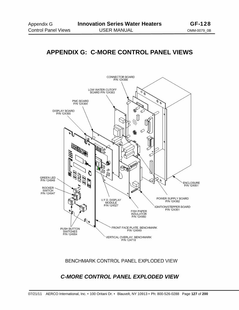
Appendix G Innovation Series Water Heaters GF-128 Control Panel Views USER MANUAL OMM-0079_0B
07/21/11 AERCO International, Inc. · 100 Oritani Dr. · Blauvelt, NY 10913 · Ph: 800-526-0288 Page 127 of 200
APPENDIX G: C-MORE CONTROL PANEL VIEWS
C-MORE CONTROL PANEL EXPLODED VIEW

GF-128 Innovation Series Water Heaters Appendix G OMM-0079_0B USER MANUAL Control Panel Views
Page 128 of 200 AERCO International, Inc. · 100 Oritani Dr. · Blauvelt, NY 10913 · Phone: 800-526-0288
C-MORE CONTROL PANEL VIEWS
C-MORE CONTROL PANEL REAR VIEW

Appendix H C-More Wiring Diagrams
Innovation Series Water Heaters USER MANUAL
APPENDIX H: C-MORE WIRING DIAGRAMS

GF-128 Innovation Series Water Heaters OMM-0079_0B USER MANUAL
This Page Is Intentionally Blank

Appendix H C-More Wiring Diagrams
Innovation Series Water Heaters USER MANUAL

GF-128 Innovation Series Water Heaters OMM-0079_0B USER MANUAL
This Page Is Intentionally Blank

Appendix H C-More Wiring Diagrams
Innovation Series Water Heaters USER MANUAL

GF-128 Innovation Series Water Heaters OMM-0079_0B USER MANUAL
This Page Is Intentionally Blank

Appendix H C-More Wiring Diagrams
Innovation Series Water Heaters USER MANUAL

GF-128 Innovation Series Water Heaters OMM-0079_0B USER MANUAL
This Page Is Intentionally Blank

Appendix I Innovation Series Water Heaters GF-128 Recommended Spares USER MANUAL OMM-0079_0B
07/21/11 AERCO International, Inc. · 100 Oritani Dr. · Blauvelt, NY 10913 · Ph: 800-526-0288 Page 137 of 200
APPENDIX I: RECOMMENDED SPARES
NOTE Refer to the Parts List Illustrations in Appendix E for the locations of the recommended and optional spare parts listed in the following Tables.
Table I-1. Recommended Emergency Spare Parts
DESCRIPTION PART NUMBER 120 VAC/Single-Phase Blower 24111 SSOV Actuator/Regulator Combo - Used on:
· ALL FM gas train models
· Downstream SSOV of DBB (IRI) gas train models
64048
SSOV Actuator Without Proof of Closure Switch - Used on:
· Upstream SSOV of DBB (IRI) gas train models
69038
Temperature Switch - Manual Reset (SEE NOTE 1) 123552
Table I-2. Spare Parts Recommended for Maintenance DESCRIPTION PART NUMBER
Annual Maintenance Kit 58036-TAB 24-month Waterside/Fireside Inspection Kit 58036-TAB
Table I-3. Optional Spare Parts DESCRIPTION PART NUMBER
C-More Control Box 181197 Burner 46023 Temperature Switch - Auto Reset (SEE NOTE 1) 123966
NOTE 1: If unit is installed in the State of Kentucky, contact your local AERCO Sales Representative for Temperature Switch rated for 200°F.

GF-128 Innovation Series Water Heaters Appendix J OMM-0079_0B USER MANUAL Recommended Spares
Page 138 of 200 AERCO International, Inc. · 100 Oritani Dr. · Blauvelt, NY 10913 · Phone: 800-526-0288 07/21/11
This Page Is Intentionally Blank

Appendix J Innovation Series Water Heaters GF-128 GF-5030 Gas Guide USER MANUAL OMM-0079_0B
07/21/11 AERCO International, Inc. · 100 Oritani Dr. · Blauvelt, NY 10913 · Ph: 800-526-0288 Page 139 of 200
APPENDIX J: GF-5030
INNOVATION WATER HEATER GAS COMPONENTS & SUPPLY DESIGN GUIDE

GF-128 Innovation Series Water Heaters Appendix J OMM-0079_0B USER MANUAL GF-5030 Gas Guide
Page 140 of 200 AERCO International, Inc. · 100 Oritani Dr. · Blauvelt, NY 10913 · Ph.: 800-526-0288 07/21/11
This Page Is Intentionally Blank

07/21/11 AERCO International, Inc. · 100 Oritani Dr. · Blauvelt, NY 10913 · Ph: 800-526-0288 Page 141 of 200
GF-5030 Gas Supply Design Guide TAG-0044_0A
GAS SUPPLY DESIGN GUIDE
Natural Gas Modulating, Condensing Water Heater Models: · INN600 · INN800 · INN1060
Released: 05/26/2011
INNOVATION Series Gas-Fired Water Heaters

Page 142 of 200 AERCO International, Inc. · 100 Oritani Dr. · Blauvelt, NY 10913 · Ph.: 800-526-0288 07/21/11
GF-5030 TAG-0044_0A Gas Supply Design Guide
Disclaimer The information contained in this manual is subject to change without notice from AERCO International, Inc. AERCO makes no warranty of any kind with respect to this material, including but not limited to implied warranties of merchantability and fitness for a particular application. AERCO International is not liable for errors appearing in this manual. Nor for incidental or consequential damages occurring in connection with the furnishing, performance, or use of this material.
Pg. 2 of 10
Technical Support: (Mon–Fri, 8am-5pm EST)
1-800-526-0288
www.aerco.com

07/21/11 AERCO International, Inc. · 100 Oritani Dr. · Blauvelt, NY 10913 · Ph: 800-526-0288 Page 143 of 200
GF-5030
Gas Supply Design Guide TAG-0044_0A
General AERCO Innovation Low NOx gas fired water heaters are modulating input devices that require an adequate volume of natural gas at constant pressure for proper operation. The gas requirements specified in this document must be satisfied to ensure efficient combustion. Designers and installers must adhere to the AERCO specifications and those of the local authorities having jurisdiction. A thorough understanding and knowledge of these guidelines is required for the successful design and installation of Innovation Low NOx series water heaters.
Gas Train Components AERCO Innovation gas-fired water heaters are equipped with a standard UL approved/FM compliant gas trains. These gas trains are factory tested and fired, with a minimum number of modular components. The gas train components have been designed to operate at high combustion efficiencies by closely controlling both the volume and air/fuel mixture to the burner. The major internal gas train components are:
* SAFETY SHUT OFF VALVE (SSOV) With BUILT-IN SUPPLY GAS REGULATOR - An electro-hydraulic gas valve, containing a proof of closure switch, is utilized to stop fuel from flowing into the gas train of the heater. This is a 100% tight shutoff device with a visible window indicator showing valve position. Reliable, and a standard industry component, this valve is factory piped with a low gas pressure switch on the inlet side of the valve which monitors the manifold pressure for minimum supply conditions. There is also a high gas pressure switch installed on the outlet side of the gas valve, which shuts down the heater if gas manifold pressures exceed maximum conditions. The actuator has a built-in regulator that replaces the need for an external supply regulator for installations that have supply pressure of up to 14.0” W.C. For installations that have supply pressure greater than 14.0” W.C., see the “Gas Pressure Requirements” section.
* AIR/FUEL VALVE - The air/fuel valve controls the volume and mixture of air and fuel in perfect proportion throughout the entire modulation range of the heater. The valve utilizes one common shaft to simultaneously vary the gas port area and air volume. The gas portion of the valve is a slide port type valve with linear proportion-to-position characteristics. The air side uses a butterfly type valve for adjusting the air volume. The driver of the valve shaft is a precision stepping motor which provides continuous positioning from full input to minimum fire. The air/fuel valve also contains two proof-of-position switches.
* CAST ALUMINUM BLOWER ASSEMBLY - A cast aluminum pre-mix blower ensures the precise mixing of air and fuel prior to entering the burner thereby providing controlled combustion.
* LOW NOx BURNER – The burner provides the actual point of air/fuel contact and combustion into the cylindrical combustion/heat exchanger. Fabricated from metal fiber mesh covering a stainless steel body, the burner is stable throughout the entire input range of the heater. The spark igniter and flame detector for the combustion supervision system are part of this assembly. The burner is easily removable from the heater.
Gas Pressure Requirements The AERCO Innovation Low NOx series heater requires a stable natural gas input pressure. The nominal inlet supply pressure to the heater is 7.0” W.C. The allowable gas inlet pressure range is 4.0” W.C. (min.) to 14.0” W.C. (max.) when firing at maximum input. A low supply gas pressure switch in each gas train prevents the heater from operating without sufficient pressure. Maximum allowable gas pressure is 14.0” W.C. Static gas pressure (when the unit is not firing) may vary, however actual gas pressure should be measured when the unit is in operation (firing). Measure the gas pressure with a manometer at the 1/8” NPT ball valve provided at the SSOV inlet. In a multiple heater installation, gas pressure should initially be set for single heater operation, and then the remaining heaters should be staged on at full fire, to insure gas pressures never fall below the minimum allowable pressure of 4.0” W.C.
An external isolation valve must be installed at each Innovation Low NOx heater, as shown in Diagram 1. This isolation valve is supplied with the heater. For installations that have greater than 14.0” W.C. supply pressure, an external lock-up type regulator must be installed downstream of the isolation valve. The lock-up type regulator(s) must be sized for at least 1,000 cfh, but no more than 1,200 cfh, per heater. External gas regulators are self-contained with tapped diaphragm vent ports allowing the diaphragm to change its position as required. These vents typically require piping to the outside. For details, refer to the paragraph titled “Venting of Gas Supply Regulators” on page 4 of this guide. The SSOV/Regulator in the gas train is factory piped and does not require any vent piping.
Pg. 3 of 10

Page 144 of 200 AERCO International, Inc. · 100 Oritani Dr. · Blauvelt, NY 10913 · Ph.: 800-526-0288 07/21/11
GF-5030 TAG-0044_0A Gas Supply Design Guide
CAUTION! THE AERCO HEATERS MUST BE ISOLATED FROM THE SYSTEM WHEN LEAK TESTING.
Drip legs are typically required at the gas supply of each heater to prevent any dirt, weld slag, or debris from entering the heater gas train inlet pipe. When multiple heaters are installed, some utilities and local codes require a full size drip leg on the main gas supply line in addition to the drip leg at each unit. The bottom of the gas drip leg(s) should be removable without disassembling any gas piping. The weight of the gas pipe should not be supported from the bottom of the drip leg. The drip leg(s) should not be used to support any or part of the gas piping.
Diagram 1. Single Heater Pipe Connections
Custom Gas Trains Some utilities, insurance carriers, and industrial customers have special requirement gas components on high input devices beyond that which are normally supplied with AERCO heaters. Secondary shutoffs, high or low pressure operators, and external regulators are typical of the requirements of gas utilities. It is mandatory that a designer or installer comply with these requirements. AERCO assumes no liability when these requirements are not satisfied for any location or installation. Contact your local gas utility for their specific requirements before installing AERCO equipment. Special gas trains with a double block and bleed (DBB) configuration (formerly IRI) are available from AERCO. Gas inlet pressure requirements are as follows:
Gas Train Natural Gas Side
DBB 7.0” W.C.
Pg. 4 of 10

07/21/11 AERCO International, Inc. · 100 Oritani Dr. · Blauvelt, NY 10913 · Ph: 800-526-0288 Page 145 of 200
GF-5030
Gas Supply Design Guide TAG-0044_0A
Gas Piping All gas piping and components must comply with NFPA local codes, and utility requirements minimum. Only gas approved fittings, valves, or pipe should be utilized.
Standard industry practice for gas piping is Schedule 40 iron pipe and fittings. All high and low gas pressure piping systems must comply with local utility and building codes.
Assembled piping should be clean of all debris, pipe chips, or foreign material to prevent any from entering the Innovation Low NOx series heater gas train. Piping should be tested as prescribed in NFPA 54. Equipment should be isolated before testing any piping system over the allowable pressure. DO NOT EXCEED 14.0” W.C.on the inlet side of the Innovation water heater at any time.
Gas Supply Main Sizing Gas pipe sizing, for either a single or multiple heater installation, shall be sized for a maximum pressure drop of 0.3” W.C., from the source to the final heater. The maximum gas flow rate required is the sum of the maximum inputs of each unit divided by the heat of combustion of the fuel supplied at the location, (approximately 1,030 BTU per cubic foot). The fuel supplier or utility should be consulted to confirm that sufficient volume and normal pressure is provided to the building at the discharge side of the gas meter or supply pipe. For existing installations with gas equipment, gas pressure should be measured with a manometer to be certain sufficient pressure is available. Before sizing gas piping, a survey of all connected gas devices should be made. Gas piping supplying more than one gas device must be able to handle the total connected input within the allowable gas pressure drop. The allowable minimum and maximum gas pressure for each device should be considered. Whenever the minimum and maximum gas pressures vary between devices, gas pressure regulators at each unit should be installed to allow regulation at any individual unit. Gas pressure must never exceed the maximum allowable rating of any connected device.
The total length of gas piping as well as fitting pressure drop must be considered when sizing the gas piping. Total equivalent length should be calculated from the meter or source location to the last heater connected on the header. Gas piping tables 1, 2 and 3 containing data extracted from NFPA 54 should be used as a minimum guideline. (See Tables on the following pages). Gas pipe size should be selected on the total equivalent length from the appropriate pressure table. The gas volume for cfh flow will be the input divided by the calorific value of the fuel to be supplied.
Gas Header Sizing Main supply gas pipe sizing should be developed for the total plant. Heater gas manifold piping should be sized based on the volume requirements and lengths between heaters and the fuel main. Multiple heater manifold sizing (Diagram 2) indicates the proper sizing for units placed on the factory standard 52” centers with 2” takeoffs for each unit. Header sizes can be either full size or stepped in size as units are connected. A typical gas piping header diagram for a 3-Module Innovation Heater Plant is illustrated in Diagram 3.
INNOVATION SERIES GAS HEADER SIZING No. of Heaters 1 2 3 4 5 6 7 8 Sch 40 Iron Pipe* 1.5” 2.5
” 3” 3.
” 4”
4” 5”
5” Diagram 2. Multiple Heater Manifold Chart
*Based on Table 1 on the following page, 1,000 cfh/unit, actual header sizes will vary with length of pipe run and fittings employed. If supply gas pressure exceeds 14.0” W.C., a single header gas manifold lock-up type regulator, -or- individual lock-up regulators can be used to bring the gas pressure down to 14.0” W.C. Header should be located above or behind heater. Gas piping should not be installed directly over top or front of any part of heater. Sufficient clearances for maintenance are required.
Pg. 5 of 10
GASSUPPLY
MANUALSHUTOFFVALVE
DRIPLEG
DRIPLEG
MANUALSHUTOFF
VALVE
Diagram 3
Typical Multiple Heater Manifold Construction

Page 146 of 200 AERCO International, Inc. · 100 Oritani Dr. · Blauvelt, NY 10913 · Ph.: 800-526-0288 07/21/11
GF-5030 TAG-0044_0A Gas Supply Design Guide
Gas Piping Tables
The data in the following pipe and vent sizing tables have been extracted from the National Fire Protection Association Article 54 (NFPA 54)
TABLE 1
Maximum Capacity of Pipe in Cubic Feet of Gas per Hour for Gas Pressures of 0.5 psi or Less and a Pressure Drop of 0.3 inch Water Column
Nominal Iron Pipe
Size (Inches)
Internal
Diameter (Inches)
Total Equivalent Length of Pipe (Feet)
10 20 30 40 50 60 70 80 90 125 150 175 200 2.00 2.067 3,050 2,100 1,650 1,450 1,270 1,150 1,050 990 930 780 710 650 610 2.50 2.469 4,800 3,300 2,700 2,300 2,000 1,850 1,700 1,600 1,500 1,250 1,130 1,050 980 3.00 3.068 8,500 5,900 4,700 4,100 3,600 3,250 3,000 2,800 2,600 2,200 2,000 1,850 1,700 4.00 4.026 17,500 12,000 9,700 8,300 7,400 6,800 6,200 5,800 5,400 4,500 4,100 3,800 3,500
TABLE 2
TABLE 3
Pipe Sizing Table for 2 Pounds Pressure Capacity of Pipes of Different Diameters and Lengths in Cubic Feet per Hour for an Initial Pressure of 2.0 psi with a 10% Pressure Drop and a Gas of 0.6 Specific Gravity
Pipe Size of Schedule 40
Standard Pipe (Inches)
Internal
Diameter (Inches)
Total Equivalent Length of Pipe (Feet) 50 100 150 200 250 300 400 500
2.00 2.067 6589 4528 3636 3112 2758 2499 2139 1896 2.50 2.469 10501 7217 5796 4961 4396 3983 3409 3022 3.00 3.068 18564 12759 10246 8769 7772 7042 6027 5342 3.50 3.548 27181 18681 15002 12840 11379 10311 8825 7821 4.00 4.026 37865 26025 20899 17887 15853 14364 12293 10895 5.00 5.047 68504 47082 37809 32359 28680 25986 22240 19711 6.00 6.065 110924 76237 61221 52397 46439 42077 36012 31917
Pg. 6 of 10
Pipe Sizing Table for 1 Pound Pressure Capacity of Pipes of Different Diameters and Lengths in Cubic Feet per Hour for an Initial Pressure of 1.0 psi with a 10% Pressure Drop and a Gas of 0.6 Specific Gravity
Pipe Size of Schedule 40
Standard Pipe (Inches)
Internal
Diameter (Inches)
Total Equivalent Length of Pipe (Feet)
50 100 150 200 250 300 400 500 2.00 2.067 4245 2918 2343 2005 1777 1610 1378 1222 2.50 2.469 6766 4651 3735 3196 2833 2567 2197 1947 3.00 3.068 11962 8221 6602 5650 5008 4538 3884 3442 3.50 3.548 17514 12037 9666 8273 7332 6644 5686 5039 4.00 4.026 24398 16769 13466 11525 10214 9255 7921 7020 5.00 5.047 44140 30337 24362 20851 18479 16744 14330 12701 6.00 6.065 71473 49123 39447 33762 29923 27112 23204 20566 8.00 7.981 146849 100929 81049 69368 61479 55705 47676 42254

07/21/11 AERCO International, Inc. · 100 Oritani Dr. · Blauvelt, NY 10913 · Ph: 800-526-0288 Page 147 of 200
GF-5030
Gas Supply Design Guide
TABLE 4
Pipe Sizing Table for 5 Pounds Pressure Capacity of Pipes of Different Diameters and Lengths in Cubic Feet per Hour for an Initial Pressure of 5.0 psi with a 10% Pressure Drop and a Gas of 0.6 Specific Gravity
Pipe Size of Schedule 40
Standard Pipe (Inches)
Internal
Diameter (Inches)
Total Equivalent Length of Pipe (Feet) 50 100 150 200 250 300 400 500
2.00 2.067 11786 8101 6505 5567 4934 4471 3827 3391 2.50 2.469 18785 12911 10368 8874 7865 7126 6099 5405 3.00 3.068 33209 22824 18329 15687 13903 12597 10782 9556 3.50 3.548 48623 33418 26836 22968 20365 18444 15786 13991 4.00 4.026 67736 46555 37385 31997 28358 25694 21991 19490 5.00 5.047 122544 84224 67635 57887 51304 46485 39785 35261 6.00 6.065 198427 136378 109516 93732 83073 75270 64421 57095
Venting of Gas Supply Regulators AERCO’s general guidelines for venting of gas regulators are listed below. AERCO recommends that these guidelines be followed to ensure the most reliable and proper operation of AERCO gas fired equipment. It is also recommended that you consult local codes and the gas regulator manufacturer for additional details. Always follow the most stringent guidelines available, including those listed below.
· When venting a gas supply regulator, the vent pipe must be no smaller than the regulator vent size. · In a multiple unit installation, each regulator must have a separate vent line. · Vent lines must not be manifolded together or with any other equipment at the site that also requires
atmospheric vents.
· When sizing the vent, pipe diameters must be increased by one pipe diameter every 20 equivalent feet of pipe. · Each 90° elbow is equivalent to approximately: Þ 2.5 feet for nominal pipe sizes of up to 3/4” Þ 4.5 feet for nominal pipe sizes of up to 1-1/2” Þ 10.5 feet for nominal pipe sizes of up to 4”
· · Each 45° elbow is equivalent to approximately: Þ 1 foot for nominal pipe sizes of up to 3/4” Þ 2 feet for nominal pipe sizes of up to 1-1/2” Þ 5 feet for nominal pipe sizes of up to 4”
Pg. 7 of 10

Page 148 of 200 AERCO International, Inc. · 100 Oritani Dr. · Blauvelt, NY 10913 · Ph.: 800-526-0288 07/21/11
GF-5030 TAG-0044_0A Gas Supply Design Guide
This Page Is Intentionally Blank
Pg. 8 of 10

07/21/11 AERCO International, Inc. · 100 Oritani Dr. · Blauvelt, NY 10913 · Ph: 800-526-0288 Page 149 of 200
GF-5030
Gas Supply Design Guide
NOTES: ______________________________________________________________________________
______________________________________________________________________________
______________________________________________________________________________
______________________________________________________________________________
______________________________________________________________________________
______________________________________________________________________________
______________________________________________________________________________
______________________________________________________________________________
______________________________________________________________________________
______________________________________________________________________________
______________________________________________________________________________
______________________________________________________________________________
______________________________________________________________________________
______________________________________________________________________________
______________________________________________________________________________
______________________________________________________________________________
______________________________________________________________________________
______________________________________________________________________________
______________________________________________________________________________
______________________________________________________________________________
Pg. 9 of 10

Page 150 of 200 AERCO International, Inc. · 100 Oritani Dr. · Blauvelt, NY 10913 · Ph.: 800-526-0288 07/21/11
GF-5030 TAG-0044_0A Gas Supply Design Guide
AERCO INTERNATIONAL, INC. 100 ORITANI DRIVE, BLAUVELT, NY 10913
Visit Us at www.aerco.com
Pg. 10 of 10

Appendix K Innovation Series Water Heaters GF-128 GF-5050 Venting Guide USER MANUAL OMM-0078_0B
07/21/11 AERCO International, Inc. · 100 Oritani Dr. · Blauvelt, NY 10913 · Ph: 800-526-0288 Page 151 of 200
APPENDIX K: GF-5050
INNOVATION WATER HEATER VENTING & COMBUSTION AIR GUIDE
GF-128 Innovation Series Water Heaters Appendix K OMM-0078_0A USER MANUAL GF-5050 Venting Guide
Page 152 of 200 AERCO International, Inc. · 100 Oritani Dr. · Blauvelt, NY 10913 · Ph.: 800-526-0288 07/21/11
This Page Is Intentionally Blank
Venting and Combustion Air Guide
07/21/11 AERCO International, Inc. · 100 Oritani Dr. · Blauvelt, NY 10913 · Ph: 800-526-0288 Page 153 of 200
GF-5050 TAG-0043_0C
VENTING & COMBUSTION AIR GUIDE
Natural Gas Modulating, Condensing Water Heater Models: · INN600 · INN800 · INN1060
Released: 07/21/2011
INNOVATION Series Gas-Fired Water Heaters

GF-5050 TAG-0043_0C Venting and Combustion Air Guide
Page 154 of 200 AERCO International, Inc. · 100 Oritani Dr. · Blauvelt, NY 10913 · Ph.: 800-526-0288 07/21/11
Disclaimer The information contained in this manual is subject to change without notice from AERCO International, Inc. AERCO makes no warranty of any kind with respect to this material, including but not limited to implied warranties of merchantability and fitness for a particular application. AERCO International is not liable for errors appearing in this manual. Nor for incidental or consequential damages occurring in connection with the furnishing, performance, or use of this material.
Pg 2 of 22
Technical Support: (Mon–Fri, 8am-5pm EST)
1-800-526-0288
www.aerco.com

Venting and Combustion Air Guide
07/21/11 AERCO International, Inc. · 100 Oritani Dr. · Blauvelt, NY 10913 · Ph: 800-526-0288 Page 155 of 200
GF-5050 TAG-0043_0C
1 CODES, SAFETY & VENTING SYSTEMS 1.1 APPLICABLE FEDERAL CODES
UNITED STATES: NFPA 54/ANSI Z223.1 National Fuel Gas Code
NFPA/ANSI 211 Chimneys, Fireplaces, Vents and Solid Fuel Burning Appliances
CANADA: CSA B149.1 Installation Codes for Gas-Burning Equipment
CSA B149.2 Installation Codes for Gas-Burning Equipment
The above listed codes contain information for gas vented appliances requiring Category II, III and IV, vent sizing, location, air space clearances to combustibles and safe installation practices. The gas vent installer must be familiar with the above codes, as well as Local Codes and Regulations.
ALL INSTALLATIONS OF WATER HEATERS AND VENTING SHOULD BE DONE ONLY BY QUALIFIED VENTING SYSTEMS PERSONNEL AND IN ACCORDANCE WITH THE MANUFACTURER’S RECOMMENDATIONS.
INSTALLING OR VENTING A HEATER OR ANY OTHER GAS APPLIANCE WITH IMPROPER METHODS OR MATERIALS MAY RESULT IN SERIOUS INJURY OR DEATH DUE TO FIRE OR TO ASPHYXIATION FROM POISONOUS GASES (CARBON MONOXIDE IS ODORLESS AND INVISIBLE).
· FOR CORRECT INSTALLATION OF VENT SYSTEM, READ ALL OF THESE
INSTRUCTIONS AND REFER TO THE VENT PIPE MANUFACTURER’S INSTRUCTIONS.
· FAILURE TO USE THE VENTING SYSTEM DESCRIBED IN THIS DOCUMENT WILL VOID THE MANUFACTURER’S WARRANTY AND MAY RESULT IN RAPID DETERIORATION OF THE VENTING SYSTEM, CREATING A POTENTIAL HEALTH HAZARD.
· FAULTY VENT INSTALLATION CAN ALLOW TOXIC FUMES TO BE
RELEASED INTO LIVING AREAS. THIS MAY CAUSE SERIOUS BODILY INJURY OR PROPERTY DAMAGE. IMPROPER ASSEMBLY MAY ALSO AFFECT VENT PERFORMANCE.
· INSTALL SEPARATE VENTS FOR FORCED EXHAUST APPLIANCES AND
NATURAL DRAFT APPLIANCES. A COMMON VENT BETWEEN NATURAL DRAFT AND FORCED EXHAUST APPLIANCES MAY CAUSE TOXIC GASES TO EXHAUST THROUGH THE NATURAL DRAFT APPLIANCE RATHER THAN TO OUTSIDE AIR. BREATHING EXHAUST GASES WILL CAUSE SERIOUS PERSONAL INJURY OR DEATH.
1.2 GAS VENT CATEGORIES
The Innovation Heater is approved for a Category IV vent configuration as well as for sealed combustion installations. Provisions for combustion and
ventilation air in accordance with Section 5.3, (Air for Combustion and Ventilation) of the National Fuel Gas Code - ANSI Z223.1, or Sections 7.2, 7.3, or 7.4 of CAN/CSA B149, Installation Codes, or applicable provisions of the local building codes.
Pg 3 of 22

GF-5050 TAG-0043_0C Venting and Combustion Air Guide
Page 156 of 200 AERCO International, Inc. · 100 Oritani Dr. · Blauvelt, NY 10913 · Ph.: 800-526-0288 07/21/11
Federal Codes have categorized gas appliances by the vented flue gas pressure and temperature as follows:
· Category I, being a gas appliance that operates with a non-positive vent (or natural drafted vent) connector with a flue gas pressure and temperature at least 140°F (60°C) above its dew point.
· Category II, being a gas appliance that operates with a non-positive vent (or natural drafted vent) connector with a flue gas pressure and temperature less than 140°F (60°C) above its dew point.
· Category III, being a gas appliance that operates with a positive vent (fan forced vent) connector with a flue gas pressure and temperature at least 140°F (60°C) above its dew point.
· Category IV, being a gas appliance that operates with a positive vent (fan forced vent) connector with a flue gas pressure and temperature less than 140°F (60°C) above its dew point.
· Direct Vent, a gas appliance is constructed and installed so that all air for combustion is derived directly from the outdoors and all flue gases are discharged to the outdoors.
1.3 CERTIFIED VENTING MATERIALS FOR FLUE PIPE SYSTYEMS Acceptable materials and manufacturers for flue vent pipe systems are listed below in Option #1 and Option #2.
The Vent Pipe Systems below are used for venting gas burning Category IV appliances. Do not use these vent pipe systems for venting appliances burning fuels such as wood, coal, oil or kerosene.
Maintain clearances from combustible construction for heater, vent connector, and steam and hot-water pipes.
Do not use these vent pipe systems for incinerators of any kind. Do not vent Innovation systems using the same vent piping as being used for either AERCO Benchmark or KC boilers.
OPTION #1 - AL29-4C STAINLESS STEEL
· Flex-L International Inc., StaR 34 Vent · Heat-Fab Inc., Saf-T Vent · Z-Flex Z-Vent · Protech System Inc., Fas N Seal Vent · Metal-Fab Inc., Corr/Guard Vent
OPTION #2 – NON-METALLIC – Use Schedule 40 or thicker, Single-wall, Uninsulated pipes When using Non-Metallic (Plastic) vent systems for Canadian installations, per CSA B149.1,use vent systems that are certified to the Standard for Type BH Gas Venting Systems, ULC-S636. The plastic components, primers and glues of the certified vent system must be from a single system manufacturer and not inter-mixed with other manufacturers vent system parts.
1. PVC
· ASTM F891 · ASTM D2665 · ASTM D1785 · ASTM D2241
Pg 4 of 22

Venting and Combustion Air Guide
07/21/11 AERCO International, Inc. · 100 Oritani Dr. · Blauvelt, NY 10913 · Ph: 800-526-0288 Page 157 of 200
GF-5050 TAG-0043_0C
2. CPVC
· ASTM D2846 · ASTM F441 · ASTM F442
1.4 FACTORY REQUIRED INLET & VENT CONNECTION COMPONENTS The following tabular listing shows the components and part numbers for connecting the air inlet and the exhaust vents for each Innovation model. Basic drawings of the connection components are shown in Figures 1.
COMPONENT
INN600 4 inch Part Numbers
INN800 & INN1060 6 inch Part Numbers
Exhaust - PVC 24287 24286
6" EXHAUST CONNECTION KIT (24286) FOR INN800 & INN1060
4" EXHAUST CONNECTION KIT (24287) FOR INN600
Figure 1. Air Inlet & Vent Connection Components
Pg 5 of 22

GF-5050 TAG-0043_0C Venting and Combustion Air Guide
Page 158 of 200 AERCO International, Inc. · 100 Oritani Dr. · Blauvelt, NY 10913 · Ph.: 800-526-0288 07/21/11
2 COMBUSTION AIR SYSTEM
AIR OPENINGS TO COMBUSTION AREA MUST NOT BE OBSTRUCTED. USING THE
FOLLOWING CHART, ADEQUATE COMBUSTION AIR CAN BE MAINTAINED.
2.1 COMBUSTION AIR REQUIREMENTS The following tabular listing shows the minimum required air openings in square inches (square centimeters) freely communicating with the outdoors for boiler/heater room combustion and ventilation air for each unit. For multiple unit installations, sum the openings for the specific heater sizes.
Minimum Required Air Openings Freely Communicating With the Outdoors For Boiler/Heater Room Combustion & Ventilation Air
Model No.
Two Sealed Combustion or Vertical Ducts Each having an opening in sq. in. (sq.cm) of:
Two Horizontal Ducts Each having an opening in square
inches of
Single Permanent
Opening
INN600 152 in2 (980 cm2) 304 in2 (1961 cm2) 202 (1303) INN800 190 in2 (1226 cm2) 380 in2 (2451 cm2) 253 (1632) INN1060 266 in2 (1716 cm2) 532 in2 (3431 cm2) 354 (2283)
1. The combustion air must be free of chlorine, halogenated hydrocarbons or other chemicals that
can become hazardous when used in gas-fired equipment. Common sources of these compounds are swimming pools, degreasing compounds, plastic processing, and refrigerants. Whenever the environment contains these types of chemicals, combustion air MUST be supplied from a clean area outdoors for the protection and longevity of the equipment and warranty validation.
2. Ventilation of the boiler/heater room must be adequate enough to provide sufficient air to
properly support combustion.
3. When combustion air is brought from outside the building, the boiler/heater room shall be provided with two permanent openings, one commencing 12 inches from the top and one commencing within 12 inches from the bottom of the room (see Figures 2 and 3). The openings shall communicate directly, or by ducts, freely with the outdoors. One of the following methods must be made to provide adequate air for ventilation and combustion.
a. When directly communicating with the outdoors, each opening shall have a minimum free
area of 1 square inch per 4,000 BTU per hour of total input rating of all equipment in the room.
b. When communicating with the outdoors by means of vertical ducts, each opening shall have a minimum free area of 1 square inch per 4,000 BTU per total input rating of all appliances in the room.
c. If horizontal ducts are used, each opening and duct shall have a minimum free area of 1 square inch per 2,000 BTU per hour of total input rating of all appliances in the room.
· Non-motorized louvers and grilles must be fixed in an open position. · Minimum screens mesh size shall not be smaller than ¼ inch mesh.
Pg 6 of 22

Venting and Combustion Air Guide
07/21/11 AERCO International, Inc. · 100 Oritani Dr. · Blauvelt, NY 10913 · Ph: 800-526-0288 Page 159 of 200
GF-5050 TAG-0043_0C
Figure 2. Combustion Air From Outside the building
COMBUSTION AIR FROM EQUIPMENT
ROOM
Figure 3. Combustion Air From Inside and Outside the Building
Pg 7 of 22

GF-5050 TAG-0043_0C Venting and Combustion Air Guide
Page 160 of 200 AERCO International, Inc. · 100 Oritani Dr. · Blauvelt, NY 10913 · Ph.: 800-526-0288 07/21/11
4. When calculating free area using louvers and grilles, the required size of the openings for
combustion, ventilation, and dilution air shall be based on the total free area of each opening.
If the free area through a designed louver or grille is known, it shall be used in calculating the size of opening required to provide the free area specified. If the louver and grille design free areas are not known, the following will be assumed for wooden louvers a 25 percent free area, and for metal louvers and grilles a 75 percent free area opening.
5. When terminating the combustion air through the roof:
a Combustion air inlet must be 3 ft below any vent outlet within 10 ft. See Figure 4. b Combustion air inlet must also face away from the vent outlet. See Figure 4.
6. All inlet air ducts must be sealed air tight.
7. When using sealed combustion, the combustion air inlet and vent outlet must be located on
the same surface (same wall, roof, etc.). See Figures 4 and 5. This is required so that equal pressure zones are acting on both the air inlet and vent outlet. This makes the installation a balanced vent system which helps maintain stable combustion characteristics.
LESS THAN 10 FT(305 CM)
MORE THAN 10 FT(305 CM)
10 FT(305 CM)
NOTE: NO HEIGHT ABOVE RIDGE REQUIRED FOR VENT TERMINATION WHEN DISTANCE FROM RIDGE IS MORE THAN 10 FT (305 CM).IF DISTANCE FROM RIDGE IS LESS THAN 10 FT (305 CM), TERMINATION MUST BE A MIN. OF 2 FT ABOVE RIDGE.
RIDGE
3 FT (91 CM) MINIMUM
3 FT (91 CM) MINIMUM
2 FT (61 CM) MIN.
Figure 4. Roof-Mounted Combustion Air Inlet & Vent Outlet Installations
Pg 8 of 22

Venting and Combustion Air Guide
07/21/11 AERCO International, Inc. · 100 Oritani Dr. · Blauvelt, NY 10913 · Ph: 800-526-0288 Page 161 of 200
GF-5050 TAG-0043_0C
COMBUSTIONAIR
Figure 5. Wall-Mounted Combustion Air Inlet & Vent Outlet Installations
2.2 COMBUSTION AIR PIPE SIZING The maximum length is the combined length of straight horizontal and vertical runs, and the equivalent straight length of fittings. The required lengths for each unit are as follows:
Model No. INN600 INN800 INN1060
Combustion Air Diameter 4” (102 mm)
6 (152 mm)
6 (152 mm)
Maximum Combustion Air Equivalent Feet (Meters)
140 (42.7 m)
140 (42.7 m)
140 (42.7 m)
Pg 9 of 22
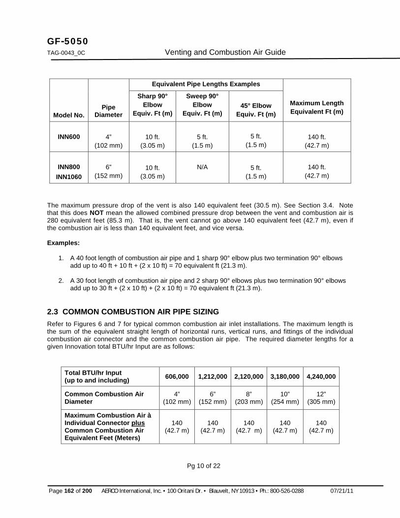
GF-5050 TAG-0043_0C Venting and Combustion Air Guide
Page 162 of 200 AERCO International, Inc. · 100 Oritani Dr. · Blauvelt, NY 10913 · Ph.: 800-526-0288 07/21/11
Model No.
Pipe Diameter
Equivalent Pipe Lengths Examples
Maximum Length Equivalent Ft (m)
Sharp 90° Elbow
Equiv. Ft (m)
Sweep 90° Elbow
Equiv. Ft (m)
45° Elbow
Equiv. Ft (m)
INN600
4”
(102 mm)
10 ft.
(3.05 m)
5 ft.
(1.5 m)
5 ft.
(1.5 m)
140 ft.
(42.7 m)
INN800 INN1060
6”
(152 mm)
10 ft.
(3.05 m) N/A
5 ft.
(1.5 m)
140 ft.
(42.7 m)
The maximum pressure drop of the vent is also 140 equivalent feet (30.5 m). See Section 3.4. Note that this does NOT mean the allowed combined pressure drop between the vent and combustion air is 280 equivalent feet (85.3 m). That is, the vent cannot go above 140 equivalent feet (42.7 m), even if the combustion air is less than 140 equivalent feet, and vice versa. Examples:
1. A 40 foot length of combustion air pipe and 1 sharp 90° elbow plus two termination 90° elbows add up to 40 ft + 10 ft + (2 x 10 ft) = 70 equivalent ft (21.3 m).
2. A 30 foot length of combustion air pipe and 2 sharp 90° elbows plus two termination 90° elbows add up to 30 ft + (2 x 10 ft) + (2 x 10 ft) = 70 equivalent ft (21.3 m).
2.3 COMMON COMBUSTION AIR PIPE SIZING Refer to Figures 6 and 7 for typical common combustion air inlet installations. The maximum length is the sum of the equivalent straight length of horizontal runs, vertical runs, and fittings of the individual combustion air connector and the common combustion air pipe. The required diameter lengths for a given Innovation total BTU/hr Input are as follows:
Total BTU/hr Input (up to and including) 606,000 1,212,000 2,120,000 3,180,000 4,240,000
Common Combustion Air Diameter
4” (102 mm)
6” (152 mm)
8” (203 mm)
10” (254 mm)
12” (305 mm)
Maximum Combustion Air à Individual Connector plus Common Combustion Air Equivalent Feet (Meters)
140 (42.7 m)
140 (42.7 m)
140 (42.7 m)
140 (42.7 m)
140 (42.7 m)
Pg 10 of 22
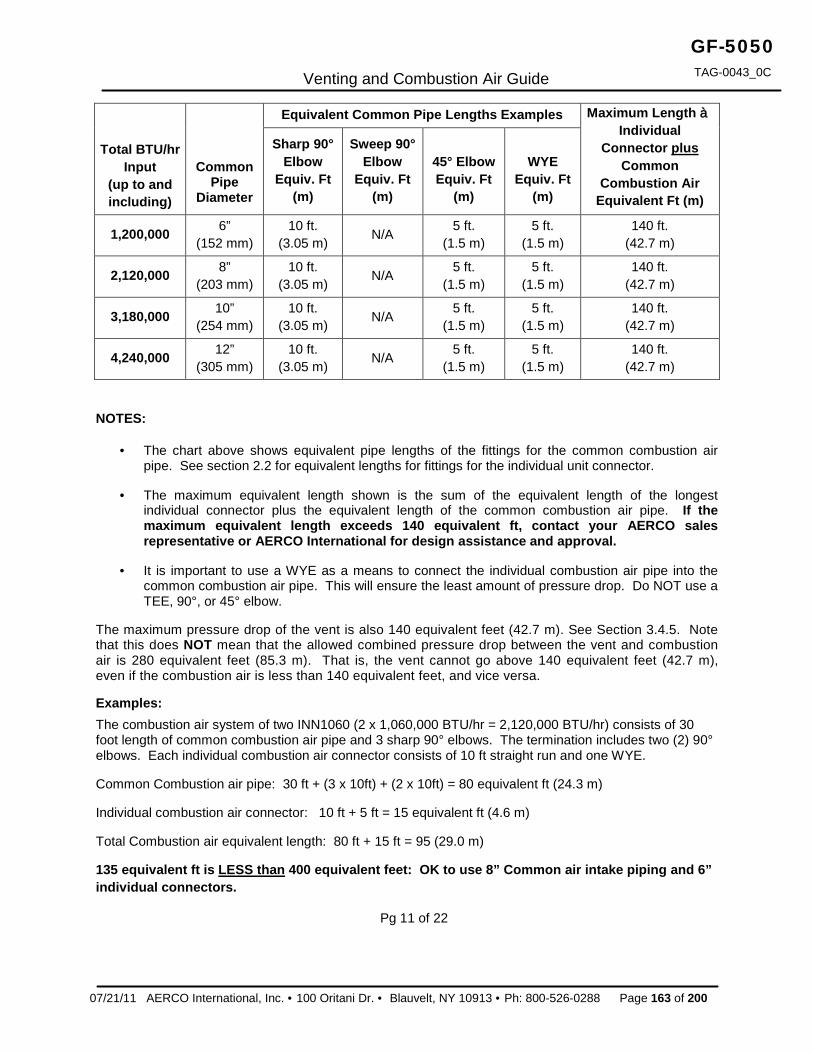
Venting and Combustion Air Guide
07/21/11 AERCO International, Inc. · 100 Oritani Dr. · Blauvelt, NY 10913 · Ph: 800-526-0288 Page 163 of 200
GF-5050 TAG-0043_0C
Total BTU/hr Input
(up to and including)
Common Pipe
Diameter
Equivalent Common Pipe Lengths Examples Maximum Length à Individual
Connector plus Common
Combustion Air Equivalent Ft (m)
Sharp 90° Elbow
Equiv. Ft (m)
Sweep 90° Elbow
Equiv. Ft (m)
45° Elbow Equiv. Ft
(m)
WYE
Equiv. Ft (m)
1,200,000 6” (152 mm)
10 ft. (3.05 m) N/A 5 ft.
(1.5 m) 5 ft.
(1.5 m) 140 ft.
(42.7 m)
2,120,000 8” (203 mm)
10 ft. (3.05 m) N/A 5 ft.
(1.5 m) 5 ft.
(1.5 m) 140 ft.
(42.7 m)
3,180,000 10” (254 mm)
10 ft. (3.05 m) N/A 5 ft.
(1.5 m) 5 ft.
(1.5 m) 140 ft.
(42.7 m)
4,240,000 12” (305 mm)
10 ft. (3.05 m) N/A 5 ft.
(1.5 m) 5 ft.
(1.5 m) 140 ft.
(42.7 m)
NOTES:
· The chart above shows equivalent pipe lengths of the fittings for the common combustion air pipe. See section 2.2 for equivalent lengths for fittings for the individual unit connector.
· The maximum equivalent length shown is the sum of the equivalent length of the longest individual connector plus the equivalent length of the common combustion air pipe. If the maximum equivalent length exceeds 140 equivalent ft, contact your AERCO sales representative or AERCO International for design assistance and approval.
· It is important to use a WYE as a means to connect the individual combustion air pipe into the common combustion air pipe. This will ensure the least amount of pressure drop. Do NOT use a TEE, 90°, or 45° elbow.
The maximum pressure drop of the vent is also 140 equivalent feet (42.7 m). See Section 3.4.5. Note that this does NOT mean that the allowed combined pressure drop between the vent and combustion air is 280 equivalent feet (85.3 m). That is, the vent cannot go above 140 equivalent feet (42.7 m), even if the combustion air is less than 140 equivalent feet, and vice versa. Examples: The combustion air system of two INN1060 (2 x 1,060,000 BTU/hr = 2,120,000 BTU/hr) consists of 30 foot length of common combustion air pipe and 3 sharp 90° elbows. The termination includes two (2) 90° elbows. Each individual combustion air connector consists of 10 ft straight run and one WYE.
Common Combustion air pipe: 30 ft + (3 x 10ft) + (2 x 10ft) = 80 equivalent ft (24.3 m)
Individual combustion air connector: 10 ft + 5 ft = 15 equivalent ft (4.6 m)
Total Combustion air equivalent length: 80 ft + 15 ft = 95 (29.0 m)
135 equivalent ft is LESS than 400 equivalent feet: OK to use 8” Common air intake piping and 6” individual connectors.
Pg 11 of 22

GF-5050 TAG-0043_0C Venting and Combustion Air Guide
Page 164 of 200 AERCO International, Inc. · 100 Oritani Dr. · Blauvelt, NY 10913 · Ph.: 800-526-0288 07/21/11
Figure 6. Roof-Mounted Combustion Air Inlet & Vent Installation
Figure 7. Wall-Mounted Combustion Air Inlet & Vent Installation
Pg 12 of 22

Venting and Combustion Air Guide
07/21/11 AERCO International, Inc. · 100 Oritani Dr. · Blauvelt, NY 10913 · Ph: 800-526-0288 Page 165 of 200
GF-5050 TAG-0043_0C
3 VENT SYSTEM The heater vent is fundamental for correct operation. Being a condensing heater, combustion gases are discharged at a very low temperature. It is therefore necessary for the venting system to be perfectly impermeable to combustion products condensate and to be made of corrosion resistant materials. Typical Category IV venting and sealed combustion illustrations are shown in Figures 2 through 5. The various funnel joints shall be well sealed and/or equipped with suitable gaskets, in order to avoid any condensate drain and/or air intake. Ensure that the heater vent’s section and height conform to national and local regulations (see 1.1 APPLICABLE FEDERAL CODES of this guide).
For water heaters designed for connection to gas vents or chimneys, vent installations shall be in accordance with Part 7, Venting of Equipment, of the National Fuel Gas Code, ANSI Z223.1, or Section 7, Venting Systems and Air Supply for Appliances, of the CAN/CSA B149, Installation Codes, or applicable provisions of the local building codes. The vent system for the Innovation heaters must be installed in accordance with AERCO’s installation instructions described in this guide.
For Category IV Heaters, the vents must be installed to prevent accumulation of condensate, and have means provided for drainage of condensate.
3.1 VENT INSTALLATION
1. The heaters covered in this section are design-certified as Category IV for venting, only when they are installed with manufacturer specified vent system components and installation practices.
2. Install vent pipe beginning at the water heater exhaust manifold vent connector and work toward the vent cap. To attach the exhaust connector to the flue collector, use the screws and the gasket supplied inside the plastic bag. Use a cross-tip (Phillips) screwdriver at least 12 inches (300 mm) long. See Figure 1 for exhaust vent connectors.
3. Vent connectors serving appliances vented by natural draft shall not be connected into any portion of mechanical draft systems operating under positive pressure
4. For Innovation water heaters, horizontal runs shall be sloping upwards not less than 1/4 inch per foot (21 mm/m) from the heater to the vent termination.
5. The instructions for the installation of the venting system shall specify that the horizontal portions of the venting system shall be supported to prevent dips or sags where condensate could collect.
6. Rigidly support vent pipe every 5 feet and at the elbows. Plumber straps may be used.
7. Clearances and enclosures. ALL vent pipe and fittings must be installed with appropriate air space clearances to combustibles. These air space clearances apply to indoor or outdoor vents, whether they are open, enclosed, horizontal or vertical or pass through floors, walls, roofs, or framed spaces. The appropriate air space clearances should be observed between joists, studs, sub floors, plywood, drywall, or plaster enclosures, insulated sheathing, rafters, roofing, and any other combustible material. The minimum air space clearance also applies to electrical wires and any kind of building insulation. For horizontal runs, maintain a minimum air space clearance of 0 inches for 4 inch and 6 inch vent pipe to any combustible material, electric wires, and building materials.
Pg 13 of 22

GF-5050 TAG-0043_0C Venting and Combustion Air Guide
Page 166 of 200 AERCO International, Inc. · 100 Oritani Dr. · Blauvelt, NY 10913 · Ph.: 800-526-0288 07/21/11
DO NOT INSULATE OR OTHERWISE WRAP VENT PIPE OR FITTINGS.
Paragraphs 3.2 and 3.3 discuss specific installation regulations for side-wall and vertical terminations, respectively.
3.2 INSTALLATION PROCEDURE FOR VENTING SYSTEM THROUGH A WALL The minimum distances from adjacent public walkways, adjacent buildings, operable windows and building openings shall not be less that those values specified in the National Fuel Gas Code, ANSI Z223.1 and/or CAN/CSA B149, Installation Codes. Minimum clearance of 4 feet (1.22 m) horizontally from, and in no case above or below, unless a 4-foot (1.22 m) horizontal distances is maintained, from electric meters, gas meters, regulators and relief equipment. Refer to the notes below and Figure 8, when determining the location of the vent outlet.
a. At least 12 inches (31 cm) above finished grade, or at least 12 inches (31 cm) above the normally expected snow accumulation level in geographical areas where snow accumulates. With a vent termination clearance of at least 4 feet (122 cm) from any air openings into a building.
b. In Massachusetts, when side-wall venting is used, the vent termination must be located a minimum of 4 feet above grade. For detailed information pertaining to side-wall venting within the Commonwealth of Massachusetts, see pages 11 and 12 in GF-128.
c. At least 3 feet (92 cm) above any forced air inlet located within 10 feet (305 cm).
d. At least 4 feet (122 cm) horizontally from electric meters, gas meters, regulators and relief equipment.
e. Do not terminate vent over public walkways or over an area where condensate or vapor could create a nuisance or hazard or could be detrimental to the operation of regulators, relief valves, or other equipment.
f. Do not locate the vent termination too close to shrubbery as flue products may stunt growth or kill them.
g. Some building materials may be affected by flue products expelled near unprotected surfaces. Sealing or shielding of exposed surfaces with a corrosion resistant material (such as aluminum sheet) may be required to prevent staining or deterioration.
h. See the National or Canadian Codes listed at the beginning of these instructions for additional information on termination location.
Pg 14 of 22

Venting and Combustion Air Guide
07/21/11 AERCO International, Inc. · 100 Oritani Dr. · Blauvelt, NY 10913 · Ph: 800-526-0288 Page 167 of 200
GF-5050 TAG-0043_0C
VEN
T TE
RM
INA
TIO
NS
MU
ST B
E A
T LE
AST
3
FEET
(92
CM
) AB
OVE
AN
Y FO
RC
ED A
IR
INLE
T LO
CA
TED
WIT
HIN
10
FEET
(305
CM
).
Figu
re 8
. A
ccep
tabl
e Ve
nt T
erm
inat
ion
Loca
tions
CA
TEG
OR
Y IV
VEN
T TE
RM
INA
TIO
NS
MU
ST N
OT
TER
MIN
ATE
OVE
R P
UB
LIC
WA
LKW
AYS
OR
OVE
R
AR
EAS
WH
ERE
CO
ND
ENSA
TE O
R V
APO
R C
OU
LD
CR
EATE
A N
UIS
AN
CE
OR
HA
ZAR
D.
Pg 15 of 22

GF-5050 TAG-0043_0C Venting and Combustion Air Guide
Page 168 of 200 AERCO International, Inc. · 100 Oritani Dr. · Blauvelt, NY 10913 · Ph.: 800-526-0288 07/21/11
3.3 INSTALLATION PROCEDURE FOR VERTICAL VENTING DO NOT INSULATE OR OTHER WISE WRAP VENT PIPE OR FITTINGS. FOLLOW THE VENT PIPE MANUFACTURERS INSTALLATION INSTRUCTIONS FOR VERTICAL VENTING.
The Vent Termination Must Be Located As Follows:
a. Combustion air inlet must be 3 ft below any vent outlet, within 10 ft. See Figure 9.
b. Vertical terminations shall extend at least 3 ft. (0.9 m) above the highest point where it passes through a roof of a building and at least 2 ft. (0.6 m) higher than any portion of the building within a horizontal distance of 10 ft. (3 m). Terminations that extend more than 2 ft above the roof must be laterally supported.
c. Combustion air inlet must also face away from the vent outlet see Figure 9.
d. Use vent pipe manufacturers vent cap, fire stop, support collar, roof flushing, and storm collar.
LESS THAN 10 FT(305 CM)
MORE THAN 10 FT(305 CM)
10 FT(305 CM)
NOTE: NO HEIGHT ABOVE RIDGE REQUIRED FOR VENT TERMINATION WHEN DISTANCE FROM RIDGE IS MORE THAN 10 FT (305 CM).IF DISTANCE FROM RIDGE IS LESS THAN 10 FT (305 CM), TERMINATION MUST BE A MIN. OF 2 FT ABOVE RIDGE.
RIDGE
3 FT (91 CM) MINIMUM
3 FT (91 CM) MINIMUM
2 FT (61 CM) MIN.
Figure 9. Acceptable Combustion Air Inlet & Vent Outlet Configuration

Venting and Combustion Air Guide
07/21/11 AERCO International, Inc. · 100 Oritani Dr. · Blauvelt, NY 10913 · Ph: 800-526-0288 Page 169 of 200
GF-5050 TAG-0043_0C
Pg 16 of 22
3.4 VENT PIPE SIZING The maximum length is the combined length of straight horizontal and vertical runs, and the equivalent straight length of fittings. The required lengths for each heater are as follows:
Model No. INN600 INN800 INN1060
Vent Diameter 4” (102 mm)
6 (152 mm)
6 (152 mm)
Maximum Vent Equivalent Feet (Meters)
140 ft. (42.7 m)
140 ft. (42.7 m)
140 ft. (42.7 m)
Equivalent Vent Length Examples
Model No.
Vent Pipe Diameter
Sharp 90° Elbow
Equiv. Ft. (m)
Sweep 90° Elbow
Equiv. Ft. (m)
45° Elbow Equiv. Ft.
(m)
Equiv. Ft.
(m)
Maximum Length
Equiv. Ft (m)
INN600
4”
(102 mm)
10 ft.
(3.05 m)
5 ft.
(1.5 m)
5 ft.
(1.5 m)
5 ft.
(1.5 m)
140 ft.
(42.7 m)
INN800 INN1060
6”
(152 mm)
10 ft.
(3.05 m) N/A
5 ft.
(1.5 m)
5 ft.
(1.5 m)
140 ft.
(42.7 m)
The maximum pressure drop of the combustion air piping is also 140 equivalent feet (42.7 m). See Section 2.2. Note that this does NOT mean the allowed combined pressure drop between the vent and combustion air is 280 equivalent feet (85.3 m). That is, the vent cannot go above 140 equivalent feet (42.7 m), even if the combustion air is less than 140 equivalent feet, and vice versa. Examples:
1. A 40 foot (12.2 m) length of vent pipe and 1 sharp 90° elbow plus a termination rain cap add up to 40 ft + 10 ft + 10 ft = 60 equivalent ft. (18.3 m)
2. A 30 foot (10.4 m) length of vent pipe and 2 sharp 90° elbows plus a termination rain add up to 30 ft + (2 x 10 ft) + 10 ft = 50 equivalent ft (18.3 m).
Pg 17 of 22

GF-5050 TAG-0043_0C Venting and Combustion Air Guide
Page 170 of 200 AERCO International, Inc. · 100 Oritani Dr. · Blauvelt, NY 10913 · Ph.: 800-526-0288 07/21/11
3.5 COMMON VENT PIPE SIZING Refer to Figures 6 and 7 in Section 2 for typical common vent installations. The maximum length is the sum of the equivalent straight length of horizontal runs, vertical runs, and fittings of the individual vent connector and the common vent pipe. The maximum length is the combined length of straight horizontal and vertical runs, and the equivalent straight length of fittings. The required diameters for a given Innovation total BTU/hr Input are as follows:
Total BTU/hr Input (up to and including) 1,212,000 2,120,000 3,180,000 4,240,000
Common Vent Diameter 6” (152 mm)
8” (203 mm)
10” (254 mm)
12” (305 mm)
Maximum Vent à Individual Connector plus Common Vent Equivalent Feet (Meters)
140 (42.7 m)
140 (42.7 m)
140 (42.7 m)
140 (42.7 m)
Total BTU/hr Input
(up to and including)
Common Vent
Diameter
Equivalent Common Vent Lengths Examples Maximum Length à Individual Connector plus Common Vent Equivalent Ft (m)
Sharp 90° Elbow
Equiv. Ft (m)
Sweep 90° Elbow
Equiv. Ft (m) 45° Elbow
Equiv. Ft (m)
WYE or Termination
Tee or Rain Cap
Equiv. Ft (m)
1,212,000 6” (152 mm)
10 ft. (3.05 m) N/A 5 ft.
(1.5 m) 5 ft.
(1.5 m) 140 ft.
(42.7 m)
2,120,000 8” (203 mm)
10 ft. (3.05 m) N/A 5 ft.
(1.5 m) 5 ft.
(1.5 m) 140 ft.
(42.7 m)
3,180,000 10” (254 mm)
10 ft. (3.05 m) N/A 5 ft.
(1.5 m) 5 ft.
(1.5 m) 140 ft.
(42.7 m)
4,240,000 12” (305 mm)
10 ft. (3.05 m) N/A 5 ft.
(1.5 m) 5 ft.
(1.5 m) 140 ft.
(42.7 m)
NOTES: · The chart above shows equivalent pipe lengths of the fittings for the common vent pipe. See
section 3.4 for equivalent lengths for fittings for the individual heater connector.
· The maximum equivalent length shown is the sum of the equivalent length of the longest individual connector plus the equivalent length of the common vent pipe. If the maximum equivalent length exceeds 140 equivalent ft, contact your AERCO sales representative or AERCO International for design assistance and approval.
· It is important to use a WYE as a means to connect the individual vent into the common vent pipe. This will ensure the least amount of pressure drop. DO NOT use a TEE, 90°, or 45° elbow.
Pg 18 of 22

Venting and Combustion Air Guide
07/21/11 AERCO International, Inc. · 100 Oritani Dr. · Blauvelt, NY 10913 · Ph: 800-526-0288 Page 171 of 200
GF-5050 TAG-0043_0C
The maximum pressure drop of the combustion air piping is also 140 equivalent feet (42.7 m). See Section 3.4. Note that this does NOT mean that the allowed combined pressure drop between the vent and combustion air is 280 equivalent feet (85.3 m). That is, the vent cannot go above 140 equivalent feet (42.7m), even if the combustion air is less than 140 equivalent feet, and vice versa. Example:
The vent system of two INN800 (2 x 800,000 BTU/hr = 1,600,000 BTU/hr) consists of 30 foot length of vent pipe and 2 sharp 90° elbows. A termination cap is also installed. Each individual vent connector consists of 5 ft straight run and one WYE.
Common Vent pipe: 30 ft + (2 x 10ft) + 5 ft = 55 equivalent ft (16.7 m) Individual vent connector: 5 ft + 5 ft = 10 equivalent ft (3.0 m) Total Vent equivalent length: 55 ft + 10 ft = 65 (19.7 m)
60 equivalent ft is LESS than 140 equivalent feet: OK to use 8” Common vent piping and 6” individual connectors.
Pg 19 of 22

GF-5050 TAG-0043_0C Venting and Combustion Air Guide
Page 172 of 200 AERCO International, Inc. · 100 Oritani Dr. · Blauvelt, NY 10913 · Ph.: 800-526-0288 07/21/11
This Page Is Intentionally Blank
Pg 20 of 22

Venting and Combustion Air Guide
07/21/11 AERCO International, Inc. · 100 Oritani Dr. · Blauvelt, NY 10913 · Ph: 800-526-0288 Page 173 of 200
GF-5050 TAG-0043_0C
NOTES: ______________________________________________________________________________
______________________________________________________________________________
______________________________________________________________________________
______________________________________________________________________________
______________________________________________________________________________
______________________________________________________________________________
______________________________________________________________________________
______________________________________________________________________________
______________________________________________________________________________
______________________________________________________________________________
______________________________________________________________________________
______________________________________________________________________________
______________________________________________________________________________
______________________________________________________________________________
______________________________________________________________________________
______________________________________________________________________________
______________________________________________________________________________
______________________________________________________________________________
______________________________________________________________________________
______________________________________________________________________________
______________________________________________________________________________
______________________________________________________________________________
Pg 21 of 22

GF-5050 TAG-0043_0C Venting and Combustion Air Guide
Page 174 of 200 AERCO International, Inc. · 100 Oritani Dr. · Blauvelt, NY 10913 · Ph.: 800-526-0288 07/21/11
AERCO INTERNATIONAL, INC. 100 ORITANI DRIVE, BLAUVELT, NY 10913
Visit Us at www.aerco.com
Pg 22 of 22

Appendix L Innovation Series Water Heaters GF-128 GF-5060 Power Guide USER MANUAL OMM-0079_0B
07/21/11 AERCO International, Inc. · 100 Oritani Dr. · Blauvelt, NY 10913 · Ph: 800-526-0288 Page 175 of 200
APPENDIX L: GF-5060
INNOVATION WATER HEATER ELECTRICAL POWER GUIDE

GF-128 Innovation Series Water Heaters Appendix L OMM-0079_B USER MANUAL GF-5060 Power Guide
Page 176 of 200 AERCO International, Inc. · 100 Oritani Dr. · Blauvelt, NY 10913 · Ph.: 800-526-0288 07/21/11
This Page Is Intentionally Blank

C-More Wiring Diag
07/21/11 AERCO International, Inc. · 100 Oritani Dr. · Blauvelt, NY 10913 · Ph: 800-526-0288 Page 177 of 200
GF-5060 TAG-0045_0A
ELECTRICAL POWER GUIDE
Natural Gas Modulating, Condensing Water Heater Models: · INN600 · INN800 · INN1060
Released: 05/26/2011
INNOVATION Series Gas-Fired Water Heaters

GF-5060 Innovation Series Water Heaters TAG-0045_0A Electrical Power Guide
Page 178 of 200 AERCO International, Inc. · 100 Oritani Dr. · Blauvelt, NY 10913 · Ph.: 800-526-0288 07/21/11
Disclaimer The information contained in this manual is subject to change without notice from AERCO International, Inc. AERCO makes no warranty of any kind with respect to this material, including but not limited to implied warranties of merchantability and fitness for a particular application. AERCO International is not liable for errors appearing in this manual. Nor for incidental or consequential damages occurring in connection with the furnishing, performance, or use of this material.
Pg. 2 of 6
Technical Support: (Mon–Fri, 8am-5pm EST)
1-800-526-0288
www.aerco.com

Electrical Power Guide
07/21/11 AERCO International, Inc. · 100 Oritani Dr. · Blauvelt, NY 10913 · Ph: 800-526-0288 Page 179 of 200
GF-5060 TAG-0045_0A
GENERAL Innovation (INN) Gas Fired Water Heaters are fully factory wired and packaged units which require simple power wiring as part of the installation. This technical guide is intended to help designers provide electrical power wiring (line voltage) to Innovation units. Control wiring details are provided in other publications depending on the intended application. This document is intended as a guide only, and cannot include all alternatives, situations, or be totally inclusive. To comply with all codes and authorities having jurisdiction, designers and installers must plan the electrical wiring carefully and execute the installation completely. Emergency shutoffs, fusible fire switches, break glass stations, and other electrical requirements should be considered and installed whenever necessary.
Heater Electrical Requirements The Innovation water heater requires 120/1Æ/60 Hz electrical supply. The distribution block for field connection is located in the upper right of the control box. All copper wire must be connected to the terminal distribution block. 110 VAC is the minimum allowable supply voltages to the unit. Lower voltages will result in increased wear and premature failure of the blower motor. Wire size and type should be made per the National Electrical Code based on length and load. Refer to Figure 1 for typical service disconnect switch location. Figure 2 shows the location of the Power Box containing the terminal block connections. The Power Box is accessed by opening the front panel door of the unit
Figure 1. Service Switch Typical Location
Pg. 3 of 6
Service Disconnect Switch
Knock-Out for alternate electricalconduit to Service Switch
Control Panel

GF-5060 TAG-0045_0A Electrical Power Guide
Page 180 of 200 AERCO International, Inc. · 100 Oritani Dr. · Blauvelt, NY 10913 · Ph.: 800-526-0288 07/21/11
2T1 6T34T2
120 VAC, 1 PHASE
L1
13NO3L2
6T34T2
2T114NO
A2
5L31L1 A1
4T2A2
3L2
5L3
14NO
A1
13NO
1L1
NEU
GND
6T32T1
TERMINAL BLOCK
UPPER RIGHT CORNER OF FRONT PANEL
POWERBOX
Figure 2. Terminal Block Location
Provisions for Service Designers must provide emergency shutoffs and other devices to satisfy electrical codes. It is also recommended to provide an electrical shutoff disconnect switch of suitable load carrying characteristics on or near each BMK boiler. No electrical boxes or field components should be mounted to the surface of the boiler or where they would interfere with the removal of the side or top panels for maintenance. The disconnect switch should be mounted near the unit as illustrated in Figure 1. Wiring conduit, EMT, or other wiring paths should not be secured to the unit, but supported externally. Electricians should be instructed as to where the wiring conduit should be located, such as away from the relief valve discharge, drains, etc. All electrical conduit and hardware should be installed so that it does not interfere with the removal of any cover, inhibit service or maintenance, or prevent access between the unit and walls or another unit. Boiler Wiring A dedicated protected circuit should be provided from the power source to the boiler. No other electrical devices should be permanently wired on the same circuit. An emergency switch (electrical shutoff) must be in series with the power to the unit. Refer to Figure 3 for the wiring connections to the terminal block contained in the unit’s Power Box. Multiple Unit Wiring Whenever multiple units are installed within the same mechanical spaces, electrical code requirements call for a single electrical shutoff for emergency use. It is the responsibility of the electrical designer to comply with local codes and regulations affecting an individual installation.
L1
GND
TERMINAL BLOCKIN POWER BOX
DISCONNECT SWITCHSINGLE-POLE, 20 AMP
L1
GND
120V/1/60Hz
1 POLE 20 AMPCIR UIT BREAKER
120 VAC, 1 PHASE
NEUNEU
Figure 3. 120V/1Æ/60 Hz Wiring Schematic
Pg. 4 of 6

Electrical Power Guide
07/21/11 AERCO International, Inc. · 100 Oritani Dr. · Blauvelt, NY 10913 · Ph: 800-526-0288 Page 181 of 200
GF-5060 TAG-0045_0A
NOTES: ______________________________________________________________________________
______________________________________________________________________________
______________________________________________________________________________
______________________________________________________________________________
______________________________________________________________________________
______________________________________________________________________________
______________________________________________________________________________
______________________________________________________________________________
______________________________________________________________________________
______________________________________________________________________________
______________________________________________________________________________
______________________________________________________________________________
______________________________________________________________________________
______________________________________________________________________________
______________________________________________________________________________
______________________________________________________________________________
______________________________________________________________________________
______________________________________________________________________________
______________________________________________________________________________
Pg. 5of 6

GF-5060 TAG-0045_0A Electrical Power Guide
Page 182 of 200 AERCO International, Inc. · 100 Oritani Dr. · Blauvelt, NY 10913 · Ph.: 800-526-0288 07/21/11
AERCO INTERNATIONAL, INC. 100 ORITANI DRIVE, BLAUVELT, NY 10913
Visit Us at www.aerco.com
Pg. 6 of 6

Appendix M Innovation Series Water Heaters GF-128 GF-5080 Sizing Guide USER MANUAL OMM-0079_0A
PR1 - 07/21/11 AERCO International, Inc. · 100 Oritani Dr. · Blauvelt, NY 10913 · Ph: 800-526-0288 Page 183 of 200
APPENDIX M: GF-5080
INNOVATION WATER HEATER COMMERCIAL LAUNDRY SIZING GUIDE

GF-128 Innovation Series Water Heaters Appendix M OMM-0079_0A USER MANUAL GF-5080 Sizing Guide
Page 184 of 200 AERCO International, Inc. · 100 Oritani Dr. · Blauvelt, NY 10913 · Ph.: 800-526-0288 07/21/11
This Page Is Intentionally Blank

07/21/11 AERCO International, Inc. · 100 Oritani Dr. · Blauvelt, NY 10913 · Ph: 800-526-0288 Page 185 of 200
GF-5080
TAG-0046_0A
COMMERCIAL LAUNDRY SIZING GUIDE
Natural Gas Modulating, Condensing Water Heater Models: · INN600 · INN800 · INN1060
Released: 05/26/2011
INNOVATION Series Gas-Fired Water Heaters

Page 186 of 200 AERCO International, Inc. · 100 Oritani Dr. · Blauvelt, NY 10913 · Ph.: 800-526-0288 07/21/11
GF-5080 TAG-0046 0A Commercial Laundry Sizing Guide
Disclaimer The information contained in this manual is subject to change without notice from AERCO International, Inc. AERCO makes no warranty of any kind with respect to this material, including but not limited to implied warranties of merchantability and fitness for a particular application. AERCO International is not liable for errors appearing in this manual. Nor for incidental or consequential damages occurring in connection with the furnishing, performance, or use of this material.
Pg. 2 of 10
Technical Support: (Mon–Fri, 8am-5pm EST)
1-800-526-0288
www.aerco.com

07/21/11 AERCO International, Inc. · 100 Oritani Dr. · Blauvelt, NY 10913 · Ph: 800-526-0288 Page 187 of 200
GF-5080
TAG-0046_0A Commercial Laundry Sizing Guide
THE AERCO INNOVATION COMMERCIAL LAUNDRY HOT WATER HEATER SYSTEM The AERCO Innovation system recommended for commercial/industrial laundries (i.e. hospital or hotel laundries) is illustrated in Figure 1 (single unit) or Figure 2 (multiple units). Because laundries are subjected to periodic surge flows, supplementary storage is usually required to keep the maximum load on a gas-fired water heater within the heater’s maximum capacity. PRINCIPAL OF OPERATION BTUs are stored in a stratified storage tank on a constant temperature-variable volume (of hot water) basis, i.e., the system depends on an absolute minimum of mixing of cold water and hot water in the tank. The discharge to the system is taken from the top of the tank and/or the heater. The supply of hot water in the upper portion of the tank is replenished at a constant rate by the heater operating at its maximum capacity. Tank storage must be large enough to accommodate the cumulative surge flows that occur in the maximum usage period. Sizing and selection of the components is covered in the following explanation and example. System set up and adjustment consists simply of setting the system final outlet temperature and adjusting one balancing cock to set the circulating pump to operate at the correct point on its curve. DETERMINATION OF LAUNDRY HOT WATER REQUIREMENTS: AVERAGE HOURLY HOT WATER RATE (AHHWR) Commercial laundry equipment generally uses two gallons or less of 180°F water per pound of cloths or linens washed. This figure is recommended by most machine manufacturers. Most “heavy” work requires a nominal one hour wash cycle, inclusive of loading and unloading the machine, and is based on a 50-60 second fill time. The use of the shorter 30 second fill time will shorten the total cycle only 3 to 4 minutes. The shorter cycles more commonly used are not shorter because of shorter fill time, but, instead, are achieved by the elimination of a suds- or rinse-cycle or both. These are generally employed with synthetic fabrics which also use lower water temperatures. Thus, the figure of two gallons/pound of fabrics being washed can be considered to be two gallons/pound of machine capacity for determination of the AHHWR. If a 30 second fill cycle is standard for the entire laundry operation, this figure might be increased 6 to 7% to 2.14 gallons/pound of machine capacity. However, the figures used are conservative enough to preclude this necessity. Average Hourly Hot Water Rate (AHHWR) = (2) • (total machine capacity in pounds)
SIZING THE INNOVATION SERIES GAS-FIRED HEATER
Heater Capacity (recovery rate) in GPM = AHHWR
= 2GPH • total machine capacity in pounds
60 mins. 60 minutes
(See Chart A for heater selection) SIZING THE STRATIFIED STORAGE TANK Approximately ⅔ of the water usage in the normal laundry machine occurs in a 20 minute time period (⅓) hour. During this period, the heater can make only half of this required amount or ⅓ of the hourly requirement. The stratified storage tank must provide the other half or ⅓ of a full hour requirement. Stratification within the tank precludes 100% usability. Standard practice has shown that the tank is able to deliver between 60% and 80% of its total capacity without excessive temperature degradation. AERCO recommends using 70% of the total capacity of an un-baffled vertical tank piped as shown in Figure 1.
Pg. 3 of 10
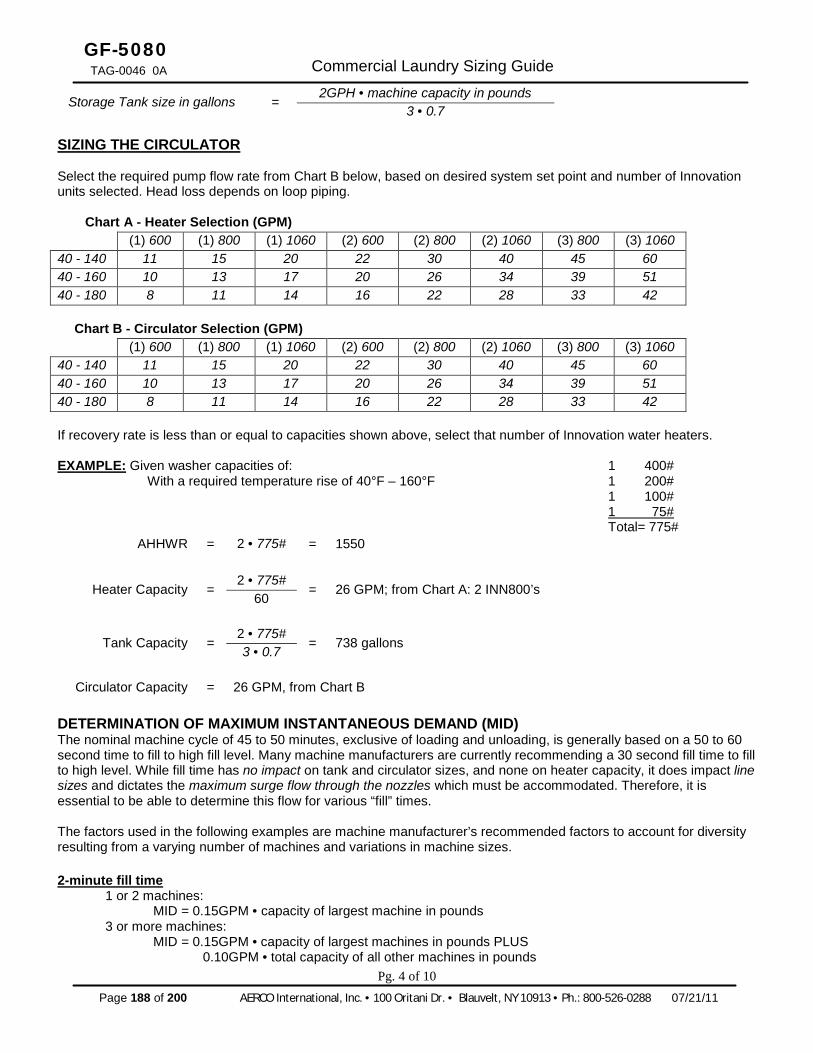
Page 188 of 200 AERCO International, Inc. · 100 Oritani Dr. · Blauvelt, NY 10913 · Ph.: 800-526-0288 07/21/11
GF-5080 TAG-0046 0A Commercial Laundry Sizing Guide
Storage Tank size in gallons = 2GPH • machine capacity in pounds
3 • 0.7 SIZING THE CIRCULATOR Select the required pump flow rate from Chart B below, based on desired system set point and number of Innovation units selected. Head loss depends on loop piping.
Chart A - Heater Selection (GPM) (1) 600 (1) 800 (1) 1060 (2) 600 (2) 800 (2) 1060 (3) 800 (3) 1060 40 - 140 11 15 20 22 30 40 45 60 40 - 160 10 13 17 20 26 34 39 51 40 - 180 8 11 14 16 22 28 33 42
Chart B - Circulator Selection (GPM) (1) 600 (1) 800 (1) 1060 (2) 600 (2) 800 (2) 1060 (3) 800 (3) 1060 40 - 140 11 15 20 22 30 40 45 60 40 - 160 10 13 17 20 26 34 39 51 40 - 180 8 11 14 16 22 28 33 42 If recovery rate is less than or equal to capacities shown above, select that number of Innovation water heaters. EXAMPLE: Given washer capacities of: 1 400# With a required temperature rise of 40°F – 160°F 1 200# 1 100# 1 75# Total= 775#
AHHWR = 2 • 775# = 1550
Heater Capacity = 2 • 775#
= 26 GPM; from Chart A: 2 INN800’s 60
Tank Capacity = 2 • 775#
= 738 gallons
3 • 0.7
Circulator Capacity = 26 GPM, from Chart B DETERMINATION OF MAXIMUM INSTANTANEOUS DEMAND (MID) The nominal machine cycle of 45 to 50 minutes, exclusive of loading and unloading, is generally based on a 50 to 60 second time to fill to high fill level. Many machine manufacturers are currently recommending a 30 second fill time to fill to high level. While fill time has no impact on tank and circulator sizes, and none on heater capacity, it does impact line sizes and dictates the maximum surge flow through the nozzles which must be accommodated. Therefore, it is essential to be able to determine this flow for various “fill” times. The factors used in the following examples are machine manufacturer’s recommended factors to account for diversity resulting from a varying number of machines and variations in machine sizes. 2-minute fill time 1 or 2 machines: MID = 0.15GPM • capacity of largest machine in pounds 3 or more machines: MID = 0.15GPM • capacity of largest machines in pounds PLUS 0.10GPM • total capacity of all other machines in pounds
Pg. 4 of 10

07/21/11 AERCO International, Inc. · 100 Oritani Dr. · Blauvelt, NY 10913 · Ph: 800-526-0288 Page 189 of 200
GF-5080
TAG-0046_0A Commercial Laundry Sizing Guide
1-minute fill time 1 or 2 machines: MID = 0.30GPM • capacity of largest machine in pounds 3 or more machines: MID = 0.30GPM • capacity of largest machines in pounds PLUS 0.15GPM • total capacity of all other machines in pounds 30-second fill time 1 or 2 machines: MID = 0.60GPM • capacity of largest machine in pounds 3 or more machines: MID = 0.60GPM • capacity of largest machines in pounds PLUS 0.25GPM • total capacity of all other machines in pounds SELECTING TANK NOZZLES AND PIPE SIZES Using the calculated MID, select a tank nozzle and pipe sizes from Chart C. Choose tank water inlet and outlet connections to keep velocities below 2 fps (feet per second). Choose sizes to velocities below 7 fps. Note on Figure 1 and Figure 2, that the piping between the tank and heater(s) does not see the MID, only the pumped flow rate. Therefore, this piping only needs to be selected for the pumped flow rate. ALTERNATE SIZING: DESIGNING FOR NO SUPLEMENTAL STORAGE In a small laundry (up to 200 pound total machine capacity, and where fill times of 1 minute or longer are acceptable), it is practical to consider the use of the AERCO Innovation heater without any supplemental storage. Heater capacity is selected equal to the maximum instantaneous demands (MID) as calculated for the standard system above. EXAMPLE (Alternate Sizing): A small laundry with incoming water 40°F in winter and water to machines 160°F has the following laundry machines: 1 with 75 pound capacity 1 with 50 pound capacity 125 pounds = Total Capacity Heater Capacity:
MID for largest machine = 75 pounds • 0.30GPM = 22.5 GPM MID for all other machines = 50 pounds • 0.15GPM = 7.5 GPM
Total MID = 30.0 GPM From Chart A, heater selection is: 2 INN1060 heaters
Pg. 5 of 10

Page 190 of 200 AERCO International, Inc. · 100 Oritani Dr. · Blauvelt, NY 10913 · Ph.: 800-526-0288 07/21/11
GF-5080 TAG-0046 0A Commercial Laundry Sizing Guide
Chart C – Velocity of water in fps (feet per second) in schedule 40 pipe for water at 60°F
GPM 2” 2 ½” 3” 3 ½” 4” 5” 6” 8” 6 0.574 8 0.765
10 0.956 0.670 15 1.43 1.01 20 1.91 1.34 0.868 25 2.39 1.68 1.09 0.812 30 2.87 2.01 1.30 0.974 35 3.35 2.35 1.52 1.14 0.882 40 3.83 2.68 1.74 1.30 1.01 45 4.30 3.02 1.95 1.46 1.13 50 4.78 3.35 2.17 4.62 1.36 60 5.74 4.02 2.60 1.95 1.51 70 6.70 4.69 3.04 2.27 1.76 1.12 80 7.65 5.36 3.47 2.60 2.02 1.28 90 8.60 6.03 3.91 2.92 2.27 1.44 100 9.56 6.70 4.34 3.25 2.52 1.60 1.11 125 11.97 8.38 5.43 4.06 3.15 2.01 1.39 150 14.36 10.05 6.51 4.87 3.78 2.41 1.67 175 16.75 11.73 7.60 5.68 4.41 2.81 1.94 200 19.14 13.42 8.68 6.49 5.04 3.21 2.22 225 15.09 9.77 7.30 5.67 3.61 2.50 1.44 250 10.85 8.13 6.30 4.01 2.78 1.60 275 11.94 8.93 6.93 4.41 3.05 1.76 300 13.00 9.74 7.56 4.81 3.33 1.92 325 14.12 10.53 8.19 5.21 3.61 2.08 350 11.36 8.82 5.62 3.89 2.34 375 12.17 9.45 6.02 4.16 2.40 400 12.98 10.08 6.42 4.44 2.56 425 13.80 10.71 6.82 4.72 2.73 450 14.61 11.34 7.22 5.00 2.89 475 11.97 7.62 5.27 3.04 500 12.60 8.02 5.55 3.21 550 13.85 8.82 6.11 3.53 600 15.12 9.63 6.66 3.85 650 10.43 7.22 4.17 700 11.23 7.78 4.49 750 12.03 8.33 4.81 800 12.83 8.88 5.13 850 13.64 9.44 5.45 900 14.44 9.99 5.77
Pg. 6 of 10
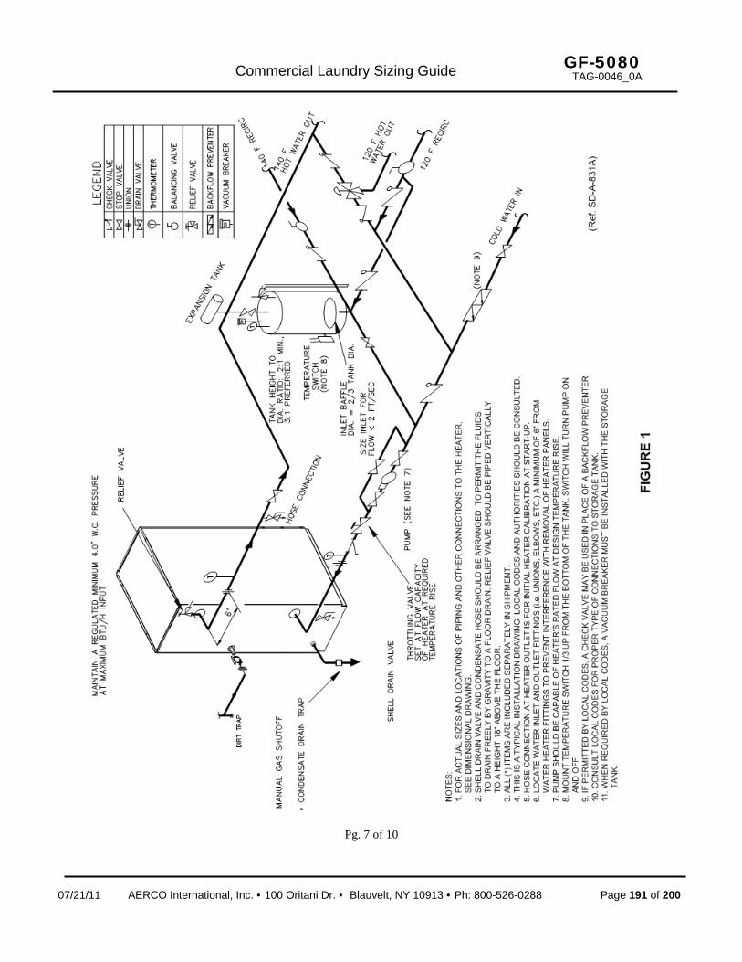
07/21/11 AERCO International, Inc. · 100 Oritani Dr. · Blauvelt, NY 10913 · Ph: 800-526-0288 Page 191 of 200
GF-5080
TAG-0046_0A Commercial Laundry Sizing Guide
Pg. 7 of 10

Page 192 of 200 AERCO International, Inc. · 100 Oritani Dr. · Blauvelt, NY 10913 · Ph.: 800-526-0288 07/21/11
GF-5080 TAG-0046 0A Commercial Laundry Sizing Guide
Pg. 8 of 10

07/21/11 AERCO International, Inc. · 100 Oritani Dr. · Blauvelt, NY 10913 · Ph: 800-526-0288 Page 193 of 200
GF-5080
TAG-0046_0A Commercial Laundry Sizing Guide
NOTES: _______________________________________________________________________________________
_______________________________________________________________________________________
_______________________________________________________________________________________
_______________________________________________________________________________________
_______________________________________________________________________________________
_______________________________________________________________________________________
_______________________________________________________________________________________
_______________________________________________________________________________________
_______________________________________________________________________________________
_______________________________________________________________________________________
_______________________________________________________________________________________
_______________________________________________________________________________________
_______________________________________________________________________________________
_______________________________________________________________________________________
_______________________________________________________________________________________
_______________________________________________________________________________________
_______________________________________________________________________________________
_______________________________________________________________________________________
_______________________________________________________________________________________
_______________________________________________________________________________________
______________________________________________________________________________________
-Pg. 9 of 10
Page 194 of 200 AERCO International, Inc. · 100 Oritani Dr. · Blauvelt, NY 10913 · Ph.: 800-526-0288 07/21/11
GF-5080 TAG-0046 0A Commercial Laundry Sizing Guide
AERCO INTERNATIONAL, INC. 100 ORITANI DRIVE, BLAUVELT, NY 10913
Visit Us at www.aerco.com
Pg. 10 of 10

APPENDIX N WARRANTY
07/21/11 AERCO International, Inc. · 100 Oritani Dr. · Blauvelt, NY 10913 · Ph: 800-526-0288 Page 195 of 200
GF-128
OMM--0079_0B
Innovation Series Water Heaters USER MANUAL
APPENDIX N: WARRANTY
INNOVATION WATER HEATER LIMITED WARRANTY

Page 196 of 200 AERCO International, Inc. · 100 Oritani Dr. · Blauvelt, NY 10913 · Ph.: 800-526-0288 07/21/11
Innovation Series Water Heaters USER MANUAL
GF-128 OMM--0079_0B
This Page Is Intentionally Blank

C-More
07/21/11 AERCO International, Inc. · 100 Oritani Dr. · Blauvelt, NY 10913 · Ph: 800-526-0288 Page 197 of 200
LIMITED WARRANTY: INNOVATION GAS-FIRED WATER HEATER
PRESSURE VESSEL: 10 YEARS NON-PRORATED The shell assembly shall carry a non-prorated 10 year limited warranty from date of shipment against leakage due to thermal shock, water side corrosion, mechanical defects or workmanship.
HEAT EXCHANGER TUBES/COMBUSTION CHAMBER: 10 YEARS The heat exchanger/combustion chamber shall carry a 10 year prorated, limited warranty from date of shipment against any condensate corrosion, thermal stress failure, mechanical defects or workmanship. Operation of the heater using contaminated air will void the warranty. The heat exchangers combustion chamber shall not be warranted from failure due to scaling, liming, corrosion, or erosion due to water or installation conditions. AERCO will repair, rebuild or exchange, at its option the heat exchanger/combustion chamber according to the following schedule:
“C-MORE” CONTROL PANEL: 2 YEARS FROM SHIPMENT AERCO labeled control panels are conditionally warranted against failure for (2) two years from shipment. OTHER COMPONENTS: 18 MONTHS FROM SHIPMENT All other components, with the exception of the igniter and flame detector, are conditionally guaranteed against any failure for 18 months from shipment. The warranty as set forth on the back page of the Operations & Maintenance Manual is in lieu of and not in addition to any other express or implied warranties in any documents, or under any law. No salesman or other representative of AERCO has any authority to expand warranties beyond the face of the said warranty and purchaser shall not rely on any oral statement except as stated in the said warranty. An Officer of AERCO must do any modifications to this warranty in writing. AERCO MAKES NO WARRANTY OF MERCHANTABILITY OR FITNESS FOR PARTICULAR PURPOSE OR ANY OTHER EXPRESS OR IMPLIED WARRANTIES. AERCO disclaims all responsibility for any special, incidental or consequential damages. Any claim relating to the product must be filed with AERCO not later than 14 days after the event-giving rise to such claim. Any claims relating to this product shall be limited to the sale price of the product at the time of sale. The sale of the product is specifically conditioned upon acceptance of these terms.
Year Discount From Then Prevailing List Price
5 100% 6 70% 7 60% 8 50% 9 40%
10 30%

Page 198 of 200 AERCO International, Inc. · 100 Oritani Dr. · Blauvelt, NY 10913 · Ph.: 800-526-0288 07/21/11
LIMITED WARRANTY: INNOVATION GAS-FIRED WATER HEATER
CONDITIONS OF WARRANTY: Should an AERCO gas-fired (natural gas, propane, and natural gas/propane dual fuel only) water heater fail for any of the above reasons within the specified time period from the date of original shipment(s), AERCO shall at its option modify, repair or exchange the defective item. AERCO shall have the option of having the item returned, FOB its factory, or to make field replacements at the point of installation. In no event shall AERCO be held liable for replacement labor charges or for freight or handling charges. AERCO shall accept no responsibility if such item has been improperly installed, operated, or maintained – as defined in AERCO O&M manual OMM-0001, or if the buyer has permitted any unauthorized modification, adjustment, and/or repairs to the item. The use of replacement parts not manufactured or sold by AERCO will void any warranty, express or limited. AERCO shall accept no responsibility if such item has been damaged due to contaminated combustion air containing but not limited to sheetrock particles, plaster board particles, dirt, dust, lint, and corrosive chemicals such as chlorine gas, halogenated hydrocarbons, and Freon. In order to process a warranty claim a formal purchase order number is required prior to shipment of any warranty item. In addition, the returned item must include a Returned Goods Authorization (RGA) label, attached to the shipping carton, which identifies the item's return address, register number and factory authorized RGA number. Warranty coverage for all components and equipment mentioned in said warranty are not valid unless the water heater is started up by a factory certified SST (Service, Start-Up and Troubleshooting) Technician and an AERCO start-up sheet is completed. This warranty coverage is only applicable within the United States and Canada. All other geographical areas carry a standard warranty of 18 months from date of shipment or 12 months from startup, whichever comes first.

Innovation Series Water Heaters GF-128 USER MANUAL OMM-0078_0B
07/21/11 AERCO International, Inc. · 100 Oritani Dr. · Blauvelt, NY 10913 · Ph: 800-526-0288 Page 199 of 200
NOTES: ______________________________________________________________________________
______________________________________________________________________________
______________________________________________________________________________
______________________________________________________________________________
______________________________________________________________________________
______________________________________________________________________________
______________________________________________________________________________
______________________________________________________________________________
______________________________________________________________________________
______________________________________________________________________________
______________________________________________________________________________
______________________________________________________________________________
______________________________________________________________________________
______________________________________________________________________________
______________________________________________________________________________
______________________________________________________________________________
______________________________________________________________________________
______________________________________________________________________________
______________________________________________________________________________
______________________________________________________________________________
______________________________________________________________________________
__________________________________________________________________________

Page 200 of 200 AERCO International, Inc. · 100 Oritani Dr. · Blauvelt, NY 10913 · Ph.: 800-526-0288 07/21/11
© AERCO International, Inc., 2011