kazarians & associates, inc. lng operations risk assessment
TRANSCRIPT
Kazarians & Associates, Inc.
LNG Operations Risk Assessment
Prepared for:
OmniTrans
San Bernardino, California
Prepared by:
Kazarians & Associates, Inc. Glendale, California 91210
1.1.1.1
1.1.1.2 May 2015
K&A Ref. No.5404.150506

Kazarians & Associates, Inc. 5404.R01.150506 i
Table of Contents
Page No.
EXECUTIVE SUMMARY ............................................................................................. E-1
1.0 INTRODUCTION AND SCOPE ........................................................................... 1
2.0 PHYSICAL PROPERTIES OF LNG AND CNG .................................................. 1
3.0 SYSTEMS INCLUDED IN THE ANALYSIS ...................................................... 2
4.0 COMPLIANCE WITH CURRENT STANDARDS .............................................. 3
5.0 SEISMIC VULNERABILITY................................................................................ 6
6.0 OVERALL APPROACH FOR ASSESSEING LNG OPERATIONS RISK ......... 7
7.0 RELEASE SCENARIO ANALYSIS ..................................................................... 9
7.1 Selection and Basis of the Scenario Identification Methodology .................9 7.2 Summary of HAZOP Methodology ..............................................................9 7.3 PHA Study Process and Results ..................................................................11
8.0 HAZARD ZONES ................................................................................................ 13 8.1 Release and Dispersion Phenomena ............................................................13
8.2 Modeling Software ......................................................................................15 8.3 Scenario Definition ......................................................................................16 8.4 Time-Limited Releases ................................................................................17
8.5 Indoor Releases and Containment Size .......................................................18 8.6 Dispersion and Hazard Zones ......................................................................19
8.7 Possibility of Explosion ...............................................................................19 8.8 BLEVE ........................................................................................................21
8.9 Assumptions ................................................................................................22
9.0 PROBABILITIES OF A HAZARDOUS EVENT ............................................... 23
9.1 Event Tree Analysis Methodology ..............................................................23 9.2 Event Probabilities ......................................................................................25
9.3 Hazard Distance vs Probability ...................................................................25
10.0 UNCERTAINTIES ............................................................................................... 27
11.0 CONCLUSIONS AND RECOMMENDATIONS ............................................... 28
12.0 REFERENCES ..................................................................................................... 34
Kazarians & Associates, Inc. 5404.R01.150506 ii
Table of Contents
Appendices
Appendix A – Properties of Natural Gas
Appendix B - Compliance with NFPA 52 Requirements
Appendix C – Industry Incidents Summary
Appendix D – HAZOP Worksheets
Appendix E – Exposure Thresholds
Appendix F – Weather Data
Appendix G – Phast Input/Output Summaries
Appendix H – Event Trees
Page No.
List of Tables
Table 1 – Guide-words Used in the Identification of Parameter Deviations .................... 10
Table 1 – Thermal Radiation Exposure Thresholds ......................................................... 14
Table 3 – Weather Condition Definitions ......................................................................... 17
Table 4 – Overpressure Exposure Thresholds .................................................................. 21
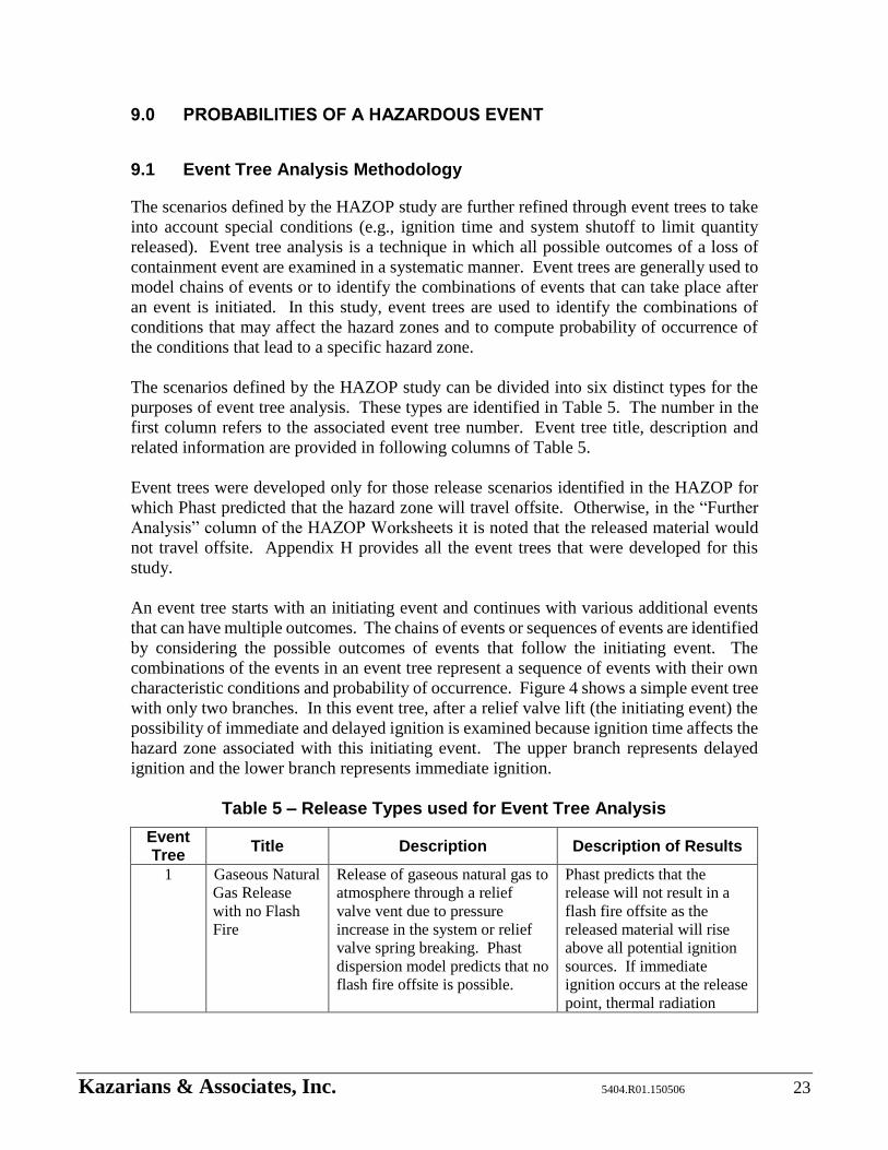
Table 5 – Release Types used for Event Tree Analysis.................................................... 23
Table 6 – Suggested Improvements .................................................................................. 31
List of Figures
Figure 1 – HAZOP Worksheet – An Example ................................................................. 13
Figure 2 – Flow Chart of Release Phenomena.................................................................. 15
Figure 3 – Initial Stages of an Accidental Release as Modelled by Phast ........................ 16
Figure 4 – Example of Event Tree 1 ................................................................................. 24
Figure 5 – Example of Hazard Distance vs Probabilities ................................................. 26
Kazarians & Associates, Inc. 5404.R01.150506 E-1
EXECUTIVE SUMMARY
OmniTrans operates a public transit bus refueling station in the City of San Bernardino that
uses Liquefied Natural Gas (LNG) to fuel buses with Compressed Natural Gas (CNG).
OmniTrans has selected Kazarians & Associates, Inc. to conduct an LNG Operations Risk
Assessment with the specific objectives of:
Ensure compliance with safety and regulatory requirements.
Review of seismic aspects of the systems
An assessment of the probability of an explosive atmosphere
Identification of potential ignition sources
A quantitative analysis of accident scenarios that includes small releases
The probability and consequences of the explosion
Study whether a hazardous or non-hazardous area exists at the fueling site.
The codes and standards that apply to LNG fueling stations are reviewed. A large number
of standards were in effects when the original LNG storage, pumping and vaporization
systems were designed and constructed. Since then, they have been consolidated into
NFPA 52, which addresses LNG storage and fueling systems. In this study, the systems
are reviewed against the current requirements and it is concluded that in general terms the
systems comply with NFPA 52 requirements. There are only a few hardware related
differences between the design and current NPFA 52 requirements. The balance of the
differences relate to administrative issues that are partly met by current practices.
The seismic ruggedness of the systems is also reviewed in this study. The standard that
was used at the time of design is compared with current standards and it is concluded that
the margin of safety used in the original design well covers the new requirements.
Additionally, a system walk-down was conducted. From that direct observation of the
physical systems a few recommendations are proposed to improve seismic safety of the
storage and handling systems.
A risk analysis is conducted to address OmniTrans objectives on the possibility of
explosion, presence of ignition sources and consequences of a release. As part of the risk
analysis, a set of potential release scenarios are identified. The hazard zone of each
scenario is estimated, and for those that can extend outside the facility boundary,
probability of occurrence is estimated. Scenarios are identified by using a well-established
method that is commonly used in the chemicals processing and petroleum refining
industries. The scenarios obtained from that analysis is further refined through the
application of event trees where various potential conditions that can influence the hazard
zone are included in the model. A wide range of scenarios are identified that includes small
and large releases depending on the specific conditions of the event. For example, a flange
failure is expected to lead to a small release, while hose break when unloading a truck is
expected to lead to a large release.

Kazarians & Associates, Inc. 5404.R01.150506 E-2
Several computer programs were examined for estimating the shape and dimensions of
potential hazard zones. Phast computer program was selected for this study since it offers
the most sophisticated features that model release of LNG. Hazard zone computations take
into account release conditions (e.g., liquid release and evaporation), formation of a gas
cloud, and ignition leading to jet fire, pool fire and flash fire. The possibility of a severe
storage tank explosion due to exposure to fire (also known as BLEVE in the industry) and
vapor cloud explosion are examined, and it is concluded that neither pose a credible threat
outside of this facility. However, several scenarios are concluded to have an impact outside
the facility boundary through thermal radiation.
Scenario probabilities are also estimated in this study using failure probabilities and human
error rates provided in various industry sources. The hazard zones are divided into two
categories: (1) potential for injury and (2) severe injury with the possibility of fatality if
the exposed person is unable to self-evacuate. The total probabilities of the two hazard
categories are concluded to be once per 3,500 years and once per 47,000 years,
respectively. These probabilities demonstrate that offsite impact of LNG operation at
OmniTrans facility is a rare event, which is also corroborated by the industry experience.
From a review of industry events since mid-1940s, none of the reported LNG release events
has adversely affected public safety. These probabilities are deemed to be conservative
given the uncertainties in the hazard zone modeling and that event probability sources tend
to report probability values conservatively. From a study of scenario probabilities and
hazard zones it is also concluded that 95% of potential injury scenarios may extend up to
880 feet from the facility boundary and 95% scenarios with the potential for severe injury
may extend up to 175 feet from the facility boundary.
As a final note, it may be added that the objective of this study does not include a
determination regarding acceptable levels of risk associated with LNG storage and
handling systems. This study is an attempt to provide sufficient information to all
stakeholders to allow them to arrive at their own conclusions. There is no regulatory
requirement for OmniTrans to modify any of its current practices, and that this study did
not discover any significant safety deficiencies. However, based on direct inspection of
the physical systems, observations of LNG receiving operations, review of current
OmniTrans practices and review of current codes and standards, suggestions for
improvements are recommended for OmniTrans management’s consideration.
Kazarians & Associates, Inc. 5404.R01.150506 1
1.0 INTRODUCTION AND SCOPE
OmniTrans operates a public transit bus refueling station in the City of San Bernardino that
uses Liquefied Natural Gas (LNG) to fuel buses with Compressed Natural Gas (CNG).
OmniTrans has selected Kazarians & Associates, Inc. to conduct an LNG Operations Risk
Assessment with the specific objectives of:
Assess the probability of an explosive atmosphere and identification of potential
ignition sources at the East Valley storage and fueling site.
Conduct a quantitative analysis that will provide a detailed study of accident
scenarios due to small releases of gas from the facility, and the
probability/consequences of the explosion as compared to other types of fuels.
Study whether a hazardous or non-hazardous area exists at the fueling site.
Review and assess the storage tanks and related operations to ensure compliance
with safety and regulatory requirements.
To achieve the last objective, municipal codes and related standards are reviewed and the
seismic aspects of the LNG facility are studied.
In this study, the various aspects of LNG storage and bus fueling operations are analyzed
from the safety perspective. The design and established practices are compared with
industry standards and practices. Recommendations are proposed to improve the systems
and related operations based on analysts’ experience and comparisons with industry
practices.
The objective of this study does not include a determination regarding acceptable levels of
risk associated with LNG storage and fueling operation. This report will attempt to provide
sufficient information to all stakeholders to allow them to arrive at their own conclusions.
In this report, compliance with applicable standards is addressed first. Seismic aspects of
the system are discussed next. The balance of this report is focused on the potential for an
accidental release and extent of hazard zones.
2.0 PHYSICAL PROPERTIES OF LNG AND CNG
Natural gas is a term used to refer to a mixture of hydrocarbon components that is typically
obtained from oil-wells. Greater than 95% of it is methane. Minor components of natural
gas include ethane, propane, butane, pentane and nitrogen. Therefore, natural gas
properties are very close to those of methane, which are used in this study where data for
natural gas was not available.

Kazarians & Associates, Inc. 5404.R01.150506 2
The boiling point of natural gas is approximately -259°F (-161°C). In order to maintain
natural gas as Liquefied Natural Gas (LNG), it must be subjected to either very high
pressure or very low temperature. At OmniTrans, LNG is maintained at low temperature
in insulated storage vessels.
When released into the atmosphere, LNG vaporizes rapidly by absorbing heat from its
surroundings. Vaporized LNG forms a very cold vapor cloud of natural gas that mixes
with air as wind blows through it. The density of cold natural gas vapor is greater than that
of air. Therefore, in the initial stages of LNG release, its vapors stay close to ground.
However, as it absorbs heat its density decreases reaching its ambient level which is much
lighter than air. At this stage, natural gas rises and dissipates into higher elevations. At
ambient temperature, liquid natural gas will expand up to 600 times its initial volume upon
vaporization.
Natural gas is a flammable substance that when released into the atmosphere it has the
potential to form a combustible vapor cloud. If its concentration in the air is within
flammable range (i.e., 5% to 15% by volume for methane), it may combust in the presence
of an ignition sources. Otherwise, the mixture in air is either too rich [i.e., above upper
flammable limit (UFL), 15%] or too lean [i.e., below lower flammable limit (LFL), 5%].
In addition to fire hazard, the low boiling point of LNG presents safety concerns of
exposure to a cryogenic material. Also, rapid vaporization of LNG can displace air and
pose asphyxiation hazard.
Properties of LNG are further discussed in Appendix A.
3.0 SYSTEMS INCLUDED IN THE ANALYSIS
This study addresses the following elements of the LNG storage and handling related
systems and operations:
Storage tanks and all the equipment located within the Storage Vault
Vaporizers
Buffer tanks and related valving and controls
Fuel dispensers
LNG truck unloading operation
LNG truck unloading operation includes truck movement within the site. Fuel dispensers
are included for the potential for inadvertent relief valve opening and dispensing hose
failure. Bus fueling operation (e.g., improper hose connection to a bus), however, is not
included in this study.

Kazarians & Associates, Inc. 5404.R01.150506 3
4.0 COMPLIANCE WITH CURRENT STANDARDS
The LNG storage and handling systems were originally designed in 2001 and construction
was completed by 2002. Since that time, the bus fueling section of the systems has been
modified. This includes relocation of the buffer tanks and control valves, relocation of fuel
dispensing stations, and the addition of a third fuel dispenser. The design of the
modifications was completed in 2012 and construction will be completed in 2015.
The design of all system components and related structures complies with the codes and
standards in effect at the time of design (i.e., 2001 for LNG storage tanks, pumps and
vaporizer and 2012 for the fuel dispensers.). A variance was issued for storage tank
placement. The codes in effect in 2002 required that the LNG storage tanks be installed
outside. The regulation also stated that the Storage Tanks must be at least 50 feet from the
nearest property. Due to the close proximity of the Storage Tanks to the fence line,
OmniTrans was granted a variance from the Occupational Safety and Health Standards
Board, allowing the Storage Tanks to be located in their current position under the
condition that they be enclosed in a containment vault [OSHSB, 2005].
At the time of the original system design a large number of codes and standards had to be
met. Under current conditions, the primary code to which an LNG fueling system must
comply with is NFPA 52 that has brought together under one document standards that
apply to the design, installation, operation, and maintenance of compressed natural gas
(CNG) and liquid natural gas (LNG) to CNG facilities, in which LNG is stored in ASME
containers of 70,000 gallons or less. Applicable portions of the following publications are
referenced within NFPA 52, and they have therefore been implicitly incorporated as a part
of this evaluation:
National Fire Protection Association
NFPA 30A, Code for Motor Fuel Dispensing Facilities and Repair Garages, 2012
Edition
NFPA 37, Standard for the Installation and Use of Stationary Combustion
Engines and Gas Turbines 2010 edition
NFPA 51B, Standard for Fire prevention During Welding, Cutting, and Other Hot
Work, 2009 edition
NFPA 54, National Fuel Gas Code, 2012 edition
NFPA 59A, Production, Storage, and Handling of Liquefied Natural Gas (LNG),
2013 edition
NFPA 70, “National Electrical Code”, 2011 Edition
NFPA 80, Standard for Fire Doors and Other Opening Protectives, 2013 edition
NFPA 259, Standard Test Method for Potential Heat of Building Materials, 2013
edition
Kazarians & Associates, Inc. 5404.R01.150506 4
NFPA 496, Standard for Purged and Pressurized Enclosures for Electrical
Equipment, 2013 edition.
NFPA-5000, Building Construction and Safety Code, 2012 edition
American Petroleum Institute
API 620, Design and Construction of Large, Welded, Low Pressure Storage Tanks,
1996
American Society of Civil Engineers
ASCE Minimum Design Loads for Buildings and Other Structures, 2010
American Society of Mechanical Engineers
ANSI/ASME B31.3, Process Piping, 2004
ASME Boiler and pressure Vessel Code, Section VIII, X, 2004
ASTM International
ASTM A 47/A47M, Standard Specification for Ferritic Malleable Iron Casting,
1999 (2009).
American National Standards Institute (ANSI)
ANSI/NGV 1, Standard for Compressed Natural Gas Vehicle Fueling Connections
Devices
ANSI/NGV 4.1, NGV Dispensing Systems
ANSI/NGV 4.2, Hoses for Natural Gas Vehicles and Dispensing Systems
ANSI/NGV 4.4, Breakaway Devices for Natural Gas Dispensing Hoses and
Systems
ANSI/NGV 4.6, Manually Operated Valves for Natural Gas Dispensing Systems
ANSI/NGV 4.7, Automatic Pressure Operated Valves for Natural Gas Dispensing
Systems
American Society of Mechanical Engineers (ASME)
Boiler and Pressure Vessel (B&PV) Code)
o Section V - Nondestructive Examination
o Section VII, Division 1 - Pressure Vessels
o Section IX - Welding and Brazing Qualifications
ASME A13.1, Scheme for the Identification of Piping Systems
ASME B16.25, Buttwelding Ends
Kazarians & Associates, Inc. 5404.R01.150506 5
ASME B31.3, Process Piping
American Society for Nondestructive Testing (ASNT)
SNT-TC-1A Recommended Practice
American Welding Society (AWS)
A5.1 Covered Carbon Steel Arc Welding Electrodes
A5.5 Low Alloy Steel Covered Arc Welding Electrodes
In addition to combining the different standards, NFPA 52 includes several revisions that
have been made since 2006. The 2006 edition of NFPA 52 was a complete revision, which
incorporated NFPA 57 “LNG Vehicular Fuel Systems Code” into NFPA 52. Additionally,
the scope of the standard was expanded to include hydrogen, and new chapters were added
that addressed general gaseous hydrogen requirements and equipment qualifications;
service and maintenance of gaseous hydrogen engine fuel systems; gaseous hydrogen
compression, gas processing, storage, and dispensing systems; and liquefied hydrogen
fueling facilities.
The 2010 edition of NFPA 52 includes revisions that mostly address hydrogen related
issues and improves the coordination between this standard and NFPA 55.
In the 2013 revision of NFPA 52 hydrogen systems related requirements are removed and
transferred to NFPA 2. A chapter on general fueling requirements was added to NPFA 52,
and changes were made to the onboard gas detection requirements for LNG-fueled
vehicles. The installation requirements for ASME Tanks for LNG were updated to
coordinate with NFPA 59A.
In this study, the design and operation of LNG storage and handling systems are reviewed
against NFPA 52 requirements to gain an understanding of the differences between systems
design and current requirements. Appendix B provides a list of the relevant requirements
of that standard along with a statement addressing level of compliance. Overall, with the
exception of one clause requiring a deflector, system design is in compliance with current
NFPA 52 requirements. According to Clause 10.2.1.8 of NFPA 52 deflectors should be
installed where there is a possibility of horizontal accidental release of LNG. All other
non-compliant clauses address administrative requirements. For example, clause 7.3.13.1.
requires a periodic hazard analysis of the systems. Recommendations are provided to
OmniTrans to consider incorporating these requirements in their current operations and
safety procedures and policies. These recommendation are further discussed in the
conclusions section of this report.
Kazarians & Associates, Inc. 5404.R01.150506 6
5.0 SEISMIC VULNERABILITY
The seismic vulnerability review focused on the following issues:
Compliance with current applicable standards
Seismic zone 4 review and its relationship with the Richter Scale
Potential mitigation plans and alternatives
Industry Standards
The design standards for the LNG storage and handling systems is comparable to standards
applicable to the chemical plants and refineries. The seismic design standards for these
type of facilities are currently based on the International Building Code [IBC, 2012],
California Building Code [CBC, 2013] and ASCE/SEI 7-10 Minimum Design Loads for
Building and Other Structures [ASCE, 2013]. These standards and building codes replaced
the Uniform Building Code standards. Based on the documentation provided, the standards
used in the design of LNG storage and handling systems was based on Uniform Building
Code 1997 [UBC, 1997] which was the building code in force at the time of the design of
the facility.
Compliance with Current Standards The available plans and documents for the existing Storage Vault and LNG storage tanks
and piping were reviewed for compliance with various standards. The following notes
summarize the observations and findings:
The existing LNG storage tanks and piping and the Storage Vault are designed
based on [UBC, 1997]. The bus fueling (dispensers) and maintenance facility and
the building that houses these systems are designed later and are based on [CBC,
2010] building and the codes in force at the time of design.
The Storage Vault and related equipment and piping are deigned based on the
requirements of Seismic Zone 4, which required the design to consider a minimum
acceleration of 0.6006g. This acceleration level is greater than that of current
requirements based on [CBC 2013] and [ASCE, 2013] for OmniTrans Facility
location. Therefore, the original design used much stricter conditions than what is
required today.
Seismic Hazard A seismic hazard analysis typically involves the consideration of all ground faults that may
affect the facility. An analysis had been done on soil and geology aspects of the site
([Byerly, 1989] and [Ninyo, 1997]) that addresses seismicity of the site. These reports
conclude that the underlying soil of OmniTrans facility is suitable for the buildings and the
facility currently constructed at this site. Underground water was not detected in the test
borings (max depth 51.5ft). Therefore, the site is not susceptible to liquefaction and
seismically induced settlement.
Ground faults that traverse near the facility are identified and analyzed for effective peak
horizontal accelerations in [Ninyo, 1997] and [Byerly, 1989]. Effective peak horizontal
Kazarians & Associates, Inc. 5404.R01.150506 7
accelerations is the bases for building codes used by structural engineers for design
purposes. According to [Ninyo, 1997] and [Byerly, 1989], San Jacinto Fault, which is
located less than one mile from the facility, may produce the largest, 0.47g, effective peak
horizontal acceleration at OmniTrans Facility. Since, in the original design 0.6006g and
in the current additions 0.484g have been used, the design of LNG storage and handling
systems is expected to withstand seismic activities generated by nearby faults.
Potential Mitigation Plans and Alternatives
Based on a site observation walkthrough, the following should be studied further:
Anchorage and foundation of the Vaporizer to verify its seismic design basis
The LNG pipe connection to the northerly site property line retaining and fence
wall to verify that pipe connections to the wall meet seismic design conditions.
The northerly site property line retaining wall and fence wall to verify its seismic
design basis
The two LNG pipe penetrations through the northerly wall of the Storage Vault and
their connections to the Vaporizers to verify that the pipe can flex under seismic
load applied to the building and the Vaporizers
Clearance between the emergency exit stair landing and the LNG storage tanks to
verify that landing structure would not collide with the nearest LNG Storage Tank
outer shell.
6.0 OVERALL APPROACH FOR ASSESSEING LNG OPERATIONS RISK
The overall analysis approach is described in this section. While this section describes the
general approach used in this study, the specifics of each part of the approach are provided
in the sections that follow.
Risk is defined as the answer to the following three questions [CCPS, 2008]:
What can go wrong?
How likely is it?
What would be the consequences?
A collection of the answers to these three questions can characterize the risk of a system or
operation. The information obtained can be manipulated in many different ways to obtain
metrics most useful to the users of the study. In this study, release scenarios that may
impact the public outside facility boundaries are identified, and their likelihoods are
estimated.

Kazarians & Associates, Inc. 5404.R01.150506 8
For the purposes of this study, the first question of risk analysis process (i.e., what can go
wrong) is focused on potential release scenarios of LNG or CNG. To identify these
scenarios, a systematic method, guideword-style Hazard and Operability (HAZOP), is
employed to minimize the chance that an important scenario is missed. This methodology
is commonly used in the chemicals processing and petroleum refining industries to evaluate
safety risk. Additionally, industry events relevant to LNG storage and handling were
reviewed to verify that the identified release scenarios capture those incidents.
The scenarios identified by HAZOP methodology are further refined by applying the Event
Tree Analysis (ETA) methodology, where additional conditions are introduced. For
example, time of ignition affects the outcome of the event. If an ignition source is present
close to the release point, the event may be limited to a pool fire. If the ignition source is
located further down-wind, there could be a potential for flash fire.
The consequences of each scenario are estimated in terms of hazard zones. Hazard zone is
defined as the specific area on the ground where a person may receive harm. Harm is
defined as exposure of the public outside of facility boundaries to fire or explosion
conditions. Exposure to extreme cold caused by an LNG spill or asphyxiation because of
displacement of air are only possible within a very short distance of an LNG spill.
Therefore, these two phenomena are not addressed as concerns for the public outside the
facility. These two phenomena present safety concerns to OmniTrans personnel only, and
are addressed through their internal safety programs.
The chain of events following a release leading up to a harmful condition on the ground
may involve multitudes of complex phenomena. They may involve such phenomena as
LNG release from a narrow opening, liquid evaporation, dispersion of gas cloud, formation
of a flammable mixture and heat flux generated by a fire after ignition. Depending on the
type of phenomena, different computational methods are employed to estimate the
parameters of these conditions with final goal of estimating the shape and extent of ensuing
hazard zone.
The likelihood or probability of each scenario depends on the initiating event of the
scenario, and other conditions that may need to be in place for a certain hazard condition
to be realized. For example, hose failure is an initiating condition that would cause spill
of LNG on the ground outside the Storage Vault. The quantity of LNG spilled will depend
on the time of emergency valve shutoff activated by the truck driver. Probability values of
each event are estimated using industry and other relevant sources.
Kazarians & Associates, Inc. 5404.R01.150506 9
7.0 RELEASE SCENARIO ANALYSIS
7.1 Selection and Basis of the Scenario Identification Methodology
The guideword-style Hazard and Operability (HAZOP) methodology [CCPS, 2008]
augmented with the “what-if” questioning process is employed to identify potential release
scenarios1. This methodology was developed in the chemicals process industry and is now
extensively used in process and refining industries to analyze safety risk of various systems
and operations and is widely accepted by regulatory agencies. The methodology provides
a systematic approach necessary to ensure that almost all important scenarios identified.
This method employs a pre-selected set of parameters and guidewords to facilitate a
thought process for identifying potentially hazardous situations or operating problems.
Automatic and manual operations (e.g., receiving LNG) of the system are analyzed using
the HAZOP study approach. Special conditions and outside influences on the system are
analyzed using the “what-if” approach.
The HAZOP methodology is based on the premise that each component or segment of a
system has a specific design intent, and a deviation from this intent may lead to a hazardous
condition. For example, an LNG Storage Tank is designed to contain a certain amount of
fluid. Maintaining the liquid level within safe limits is a design intent of operating the
vessel. If a vessel is overfilled (a deviation from the design intent) the pressure in the
system may increase and a relief valve may lift to reduce the pressure. If the vessel level
drops below a certain level (also a deviation), pump cavitation and operational problems
may be experienced.
7.2 Summary of HAZOP Methodology
In a HAZOP study, the system is divided into nodes (segments, or process sections). The
nodes may be selected based on the conditions of the effluents in the system. Typically,
nodes are selected based on changes in the physical conditions of the effluent, that is,
changes in pressure, temperature, composition, etc. Vessels, heat exchangers and pumping
devices are typical points around which a node may be selected.
For each node, the design intent is specified. Based on the design intent, the parameters
that describe various conditions of the node are identified. Parameters may include
temperature, pressure, flow, composition, etc. Deviations are identified from the
application of a standard set of guidewords to the parameters. For example, if the
guideword "less" is applied to the parameter "level," the deviation "lower level" is
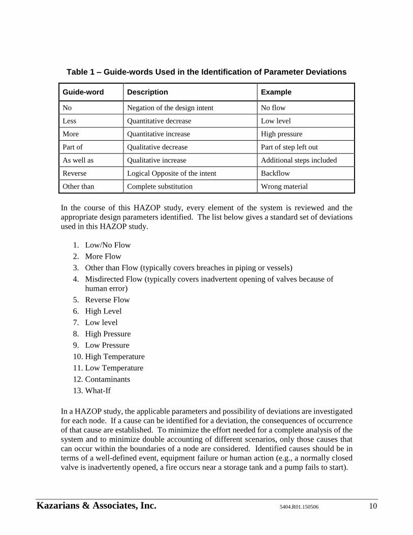
achieved. Table 1 shows the standard set of guidewords [CCPS, 2008].
1 Generally, HAZOP studies in the process industry is conducted with the participation of a team familiar with the design
and operation of the system. In this study, the analysis was conducted by the engineers at Kazarians & Associates, Inc.
A similar study that had been conducted by Loss Control Associates, Inc. [Loss Control, 2001] was consulted. Kazarians
analysis team also consulted with an engineer from NorthStar Engineering, who was involved in the construction of the
system and continues to provide services. Additionally, Kazarians analysis team observed two LNG delivery operations.
Kazarians & Associates, Inc. 5404.R01.150506 10
Table 1 – Guide-words Used in the Identification of Parameter Deviations
Guide-word Description Example
No Negation of the design intent No flow
Less Quantitative decrease Low level
More Quantitative increase High pressure
Part of Qualitative decrease Part of step left out
As well as Qualitative increase Additional steps included
Reverse Logical Opposite of the intent Backflow
Other than Complete substitution Wrong material
In the course of this HAZOP study, every element of the system is reviewed and the
appropriate design parameters identified. The list below gives a standard set of deviations
used in this HAZOP study.
1. Low/No Flow
2. More Flow
3. Other than Flow (typically covers breaches in piping or vessels)
4. Misdirected Flow (typically covers inadvertent opening of valves because of
human error)
5. Reverse Flow
6. High Level
7. Low level
8. High Pressure
9. Low Pressure
10. High Temperature
11. Low Temperature
12. Contaminants
13. What-If
In a HAZOP study, the applicable parameters and possibility of deviations are investigated
for each node. If a cause can be identified for a deviation, the consequences of occurrence
of that cause are established. To minimize the effort needed for a complete analysis of the
system and to minimize double accounting of different scenarios, only those causes that
can occur within the boundaries of a node are considered. Identified causes should be in
terms of a well-defined event, equipment failure or human action (e.g., a normally closed
valve is inadvertently opened, a fire occurs near a storage tank and a pump fails to start).

Kazarians & Associates, Inc. 5404.R01.150506 11
Consequences are the result of the deviation cause and may be expressed in terms of system
condition, release of materials, effects on other equipment, deterioration of equipment,
adverse effects on workers and the public, etc. When expressing the consequences of a
deviation, no limits are imposed in terms of location and area. Consequence discussions
are carried out until all possible adverse conditions are identified.
The possibility of occurrence of the cause of a deviation and severity of the consequences
may be mitigated by existing system features, plant characteristics, and administrative
controls (collectively referred to as safeguards). Existing safeguards are noted in the next
step of HAZOP discussions. Safeguards include such features as relief devices, gas
detectors, maintenance practices and operator training.
7.3 PHA Study Process and Results
Documents Reviewed The following documents are used in the HAZOP study to define the system:
“OmniTrans – San Bernardino, LCNG Transit Station, P&ID”, Drawing 21003-20,
Revision B, December 2001.
“OmniTrans – San Bernardino, LCNG Transit Station, P&ID”, Drawing 21003-20A,
Revision B, December 2001.
“OmniTrans – San Bernardino, LCNG Transit Station, P&ID”, Drawing 21003-21,
Revision B, December 2001.
“OmniTrans – San Bernardino, LCNG Transit Station, P&ID”, Drawing 21003-22,
Revision B, December 2001.
“OmniTrans – San Bernardino, LCNG Transit Station, P&ID”, Drawing 21003-23,
Revision B, December 2001.
“LNG Offload Gas Monitoring Procedure”, April 2003.
“Process Hazard Analysis”, LNG-CNG Fueling System, OmniTrans East Valley, April
2014.
The following documents and information sources were consulted to ensure that all
accident scenarios discussed in them are addressed in the HAZOP study:
“OmniTrans East Valley LNG – CNG Facility, San Bernardino, CA August 21 & 22,
2001”, Process Hazard Analysis. Loss Control Associates, Inc. 2001.
Industry Incidents Summary (see Appendix C)

Kazarians & Associates, Inc. 5404.R01.150506 12
Definition of the Nodes
The system is divided into the following nodes:
Node Description
1 LNG Storage Tanks (V-100 and V-150)
2 LNG from LNG Storage Tank through LNG Pumps (P-200
or P-210) to Positive Displacement LNG Pumps (P-300, P-
310, and P-320)
3 Positive Displacement LNG Pumps (P-300, P-310, and P-
320) through liquid natural gas Vaporizers (H-400 or H-410)
4 CNG from Vaporizers to Buffer System and Dispensing
5 Truck offloading to LNG Storage Tanks (V-100 and V-150)
Assumptions
The analysis is based on the following assumptions:
All maintenance contractors and vendor truck drivers are properly trained on their
assigned tasks and industry accepted safe work practices.
Since they are located inside the Pump Pots, loss of flow to a centrifugal LNG Pump
would not lead to any leaks.
The likelihood of a check valve to stick open is sufficiently small to not warrant
consideration (note that check valves may leak but are very unlikely to cause a severe
pressure boundary failure).
HAZOP Worksheets
The analysis is recorded in a standardized worksheet where the node, deviation, cause,
consequence and safeguards are noted in separate columns. If a scenario leads to an
adverse condition, a reference is added in the last column titled as “Further Analysis”
directing the reader to other studies where the hazard zone of the scenario is estimated.
Appendix D provides a complete set of the HAZOP worksheets developed for this study.
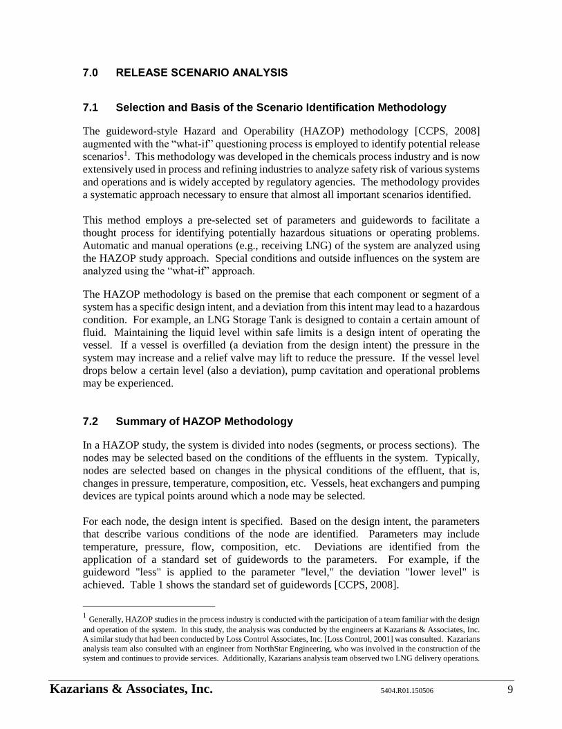
Figure 1 provides an example where three scenarios are included. The first scenario in
Figure 1 describes a 1” pipe break that occurs outside the LNG Storage Vault upstream of
the Vaporizer. This scenario is postulated in Node 3 as part of “Other than Flow” deviation.
The entries in “Further Analysis” column refer to the event tree and hazard zone analysis
cases associated with this scenario. Hazard zone analysis, as discussed later in this report,
is based on the assumption that none of the safeguards are in place. Later when the
likelihood of the scenario is estimated, failure probabilities of the safeguards are included
in those computations. The second example refers to a drain valve left open due to operator
error that leads to vapor release from the vent pipe above the roof line. Hazard zone
analysis has concluded that the gas would disperse upwards and would not pose a hazard
to the public. This is noted in the “Further Analysis” column and the analysis case is
referenced.
Kazarians & Associates, Inc. 5404.R01.150506 13
Safeguards that are credited as a protection layer are prefaced with a “*” (protection layers
are discussed in Section 7.4).
Figure 1 – HAZOP Worksheet – An Example
8.0 HAZARD ZONES
8.1 Release and Dispersion Phenomena
Upon LNG or CNG release, a chain of events unfolds that depend on the release conditions,
location of release, presence of an ignition source and weather condition. A multitude of
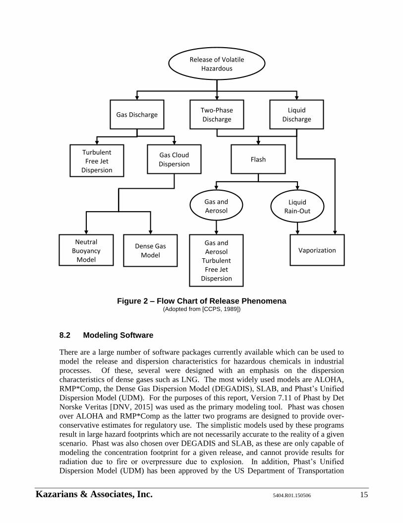
complex thermodynamic phenomena dictate the outcome of the chain of events. Figure 2
provides a graphical representation of the various phenomena and their inter-relationships.
Each scenario starts with an accidental release. The parameters of interest in that part of
the chain of events includes the phase (liquid or gas), release rate and total quantity
released. Phase depends on the location of the breach in the system. For example, a hose
break would result in a liquid release, while a pre-mature relief valve lift would release gas.
The release rate depends on the phase, size of the opening and pressure behind the release
point.

Kazarians & Associates, Inc. 5404.R01.150506 14
In case of liquid release, LNG will evaporate rapidly and form a dense cloud that will
disperse by the wind. In this case, depending on the rate of release, a pool of LNG may
form that will then evaporate and feed gas into the cloud. In case of gas release, the vapor
would form a cloud upon release.
Location of an ignition source affects the size and shape of the hazard zone. If there is an
ignition source near the release point (also known as immediate ignition), the material will
ignite close to the source forming either a jet fire, pool fire, or both. A jet fire occurs when
the material is released under pressure from an opening. If the ignition source is away from
the release point, released gas would have an opportunity to form a flammable cloud as it
is being pushed down the wind, that may then ignite leading either to an explosion or flash
fire that would flash back to the source.
The hazard zone of released LNG and CNG, therefore, depends on the specific conditions
of the release. In case of immediate ignition, the hazard zone would be determined by
thermal radiation from the jet and pool fire. In case of delayed ignition, it would be
determined by the size and shape of the gas cloud. In both cases, the hazard zone depends
on the quantity of heat imparted onto a person standing on the ground. Table 2 represents
the damage thresholds used in this analysis to determine the potential impact of public
exposure to heat from a fire. Appendix E provides the bases of the threshold values
selected for this study.
Table 1 – Thermal Radiation Exposure Thresholds
Thermal Radiation Flux Impact
2 (kW/m2) Pain from exposure in 60 seconds
5 (kW/m2) Second degree burns in 60 seconds
(minor injury in 30 seconds)
10 (kW/m2) Lethal in 60 seconds (possible
fatality)
In the case of delayed ignition, weather condition has an important role in establishing the
size and shape of the gas cloud that may remain within the flammable range. Air enters
the gas cloud because of the turbulent effects of the wind and diffusion. Generally, low
wind speeds are more stable and, therefore, the gas cloud would mix with air at a slower
rate leading to a longer gas cloud within flammable concentration range. At higher wind
speeds, the air is more turbulent, enhancing the mixing process. The net effect of this
condition is a shorter distance where the gas cloud remains within its flammable range.
Appendix F provides information about the weather patterns near the facility.
To estimate the hazard zone of a release, computational methods are needed that take into
account the multitude of phenomena discussed above. Computerized method are needed
for this purpose which are discussed below.
Kazarians & Associates, Inc. 5404.R01.150506 15
Figure 2 – Flow Chart of Release Phenomena (Adopted from [CCPS, 1989])
8.2 Modeling Software
There are a large number of software packages currently available which can be used to
model the release and dispersion characteristics for hazardous chemicals in industrial
processes. Of these, several were designed with an emphasis on the dispersion
characteristics of dense gases such as LNG. The most widely used models are ALOHA,
RMP*Comp, the Dense Gas Dispersion Model (DEGADIS), SLAB, and Phast’s Unified
Dispersion Model (UDM). For the purposes of this report, Version 7.11 of Phast by Det
Norske Veritas [DNV, 2015] was used as the primary modeling tool. Phast was chosen
over ALOHA and RMP*Comp as the latter two programs are designed to provide over-
conservative estimates for regulatory use. The simplistic models used by these programs
result in large hazard footprints which are not necessarily accurate to the reality of a given
scenario. Phast was also chosen over DEGADIS and SLAB, as these are only capable of
modeling the concentration footprint for a given release, and cannot provide results for
radiation due to fire or overpressure due to explosion. In addition, Phast’s Unified
Dispersion Model (UDM) has been approved by the US Department of Transportation
Release of Volatile Hazardous Substance
Gas Discharge Two-Phase Discharge
Liquid Discharge
Turbulent Free Jet
Dispersion
Gas Cloud Dispersion
Flash
Gas and Aerosol
Liquid Rain-Out
Gas and Aerosol
Turbulent Free Jet
Dispersion
Vaporization Dense Gas
Model
Neutral Buoyancy
Model

Kazarians & Associates, Inc. 5404.R01.150506 16
Pipeline and Hazardous Materials Safety Administration (PHMSA) for modeling of
accidental releases of LNG [Quarterman, 2011].
Phast’s UDM is able to provide results for discharge, dispersion, flammable, and explosive
calculations for accidental releases of hazardous substances [Witlox, 2015]. In modeling
a release from a vessel, Phast considers flashing of a liquid release into two-phase flow,
condensation into liquid droplets, rainout, pool formation, and evaporation. Figure 3
provides a visual representation of the various aspects of a release as modeled by Phast
[Shaba, 2013].
Figure 3 – Initial Stages of an Accidental Release as Modelled by Phast (Adopted from [Shaba, 2013])
Following a release, Phast takes into account wind speed, ambient temperature,
atmospheric stability, surface roughness, and other weather conditions in order to
determine the behavior of the resultant vapor cloud as it travels downwind. In the case of
flammable material such as LNG, Phast is able to calculate potential hazard zones based
on thermal radiation due to a fire, or overpressure due to an explosion.
8.3 Scenario Definition
Following the scenario identification process, each potential release scenario from the
HAZOP study is assigned to a release category. For example, in Figure 1 in Further
Analysis column, “HP Liquid Spill 4” and “LP Liquid Venting 6” are two release categories
assigned to the corresponding release scenarios. Since many of the scenarios in the
HAZOP study lead to the same conditions, they are grouped into release categories that
identifies the specific input parameters to be used with the modeling software. Each release
category, along with the relevant Phast inputs and outputs, can be found in Appendix G.
Kazarians & Associates, Inc. 5404.R01.150506 17
It should be noted that based on variations in the process conditions which could impact
the results some HAZOP scenarios may lead to more than one release category. For
example, in Figure 1 “LP Liquid Venting 6” and “Storage Tank Spill 2” are assigned to the
second scenario because in that scenario it is possible for an operator to close the drain
valve upon noticing the spill on the roof. The first category (i.e., “LP Liquid Venting 6”)
represents a release duration of 30 seconds and the second category (i.e., “Storage Tank
Spill 2”) represents a continuous release until the affected storage is emptied. As another
example, if a PSV on top of an LNG Storage Tank spuriously lifts, the liquid level in the
Tank could be one third full, leading to an increased pressure release, or the Tank could be
completely full, leading to a larger quantity of material released, but at a lower pressure.
In this case, the spurious PSV lift identified in the HAZOP is tied to both “LP Vapor
Venting 1” and “LP Vapor Venting 2” release categories for modeling purposes.
As discussed in the previous sections, following an accidental release of natural gas,
ambient conditions have a significant impact on the dispersion of the resultant spill.
Appendix F provides historical weather data for the San Bernardino area, which is used to
define the weather conditions analyzed in this report. For each release scenario, three
weather conditions are analyzed in terms of their ambient temperature, wind speed, and
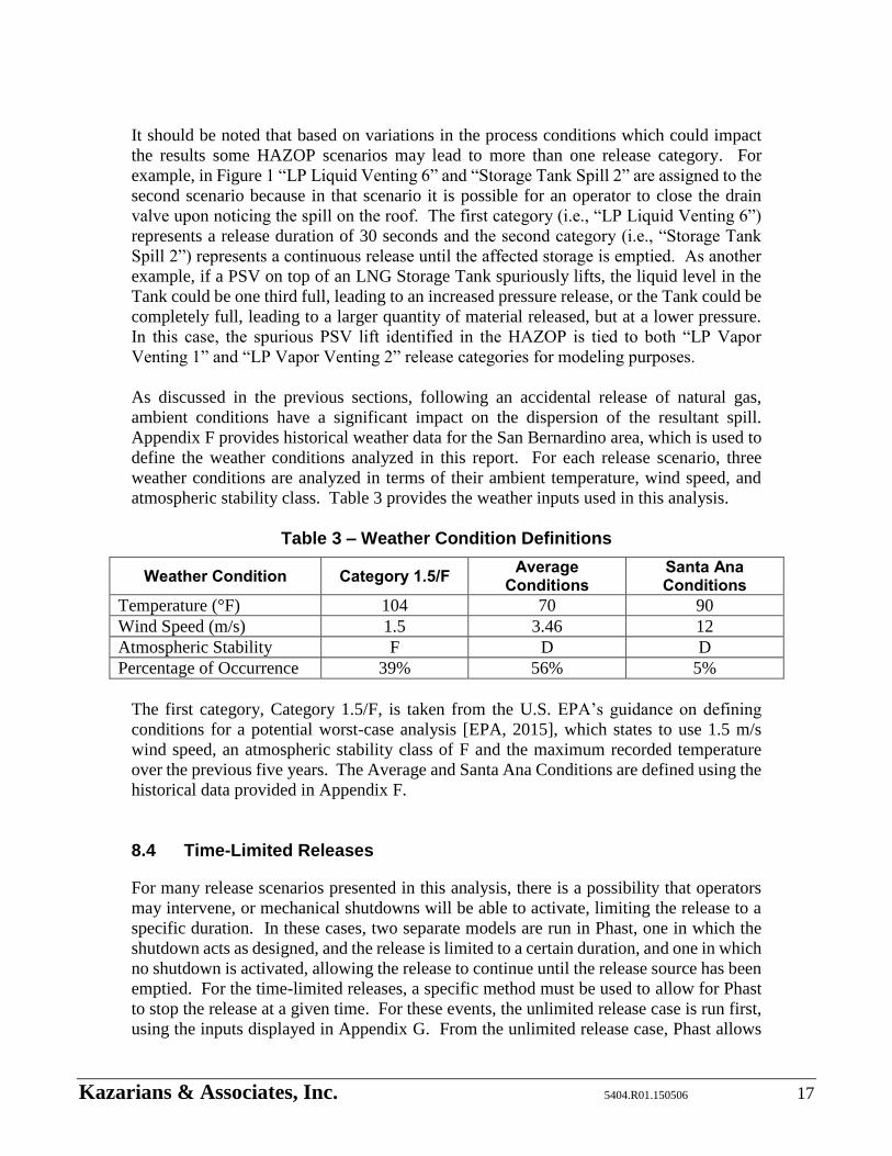
atmospheric stability class. Table 3 provides the weather inputs used in this analysis.
Table 3 – Weather Condition Definitions
Weather Condition Category 1.5/F Average
Conditions Santa Ana Conditions
Temperature (°F) 104 70 90
Wind Speed (m/s) 1.5 3.46 12
Atmospheric Stability F D D
Percentage of Occurrence 39% 56% 5%
The first category, Category 1.5/F, is taken from the U.S. EPA’s guidance on defining
conditions for a potential worst-case analysis [EPA, 2015], which states to use 1.5 m/s
wind speed, an atmospheric stability class of F and the maximum recorded temperature
over the previous five years. The Average and Santa Ana Conditions are defined using the
historical data provided in Appendix F.
8.4 Time-Limited Releases
For many release scenarios presented in this analysis, there is a possibility that operators
may intervene, or mechanical shutdowns will be able to activate, limiting the release to a
specific duration. In these cases, two separate models are run in Phast, one in which the
shutdown acts as designed, and the release is limited to a certain duration, and one in which
no shutdown is activated, allowing the release to continue until the release source has been
emptied. For the time-limited releases, a specific method must be used to allow for Phast
to stop the release at a given time. For these events, the unlimited release case is run first,
using the inputs displayed in Appendix G. From the unlimited release case, Phast allows
Kazarians & Associates, Inc. 5404.R01.150506 18
the user to “Create Source,” which creates a second scenario using the same release results
calculated in the parent case. This new source can then be manually altered to allow the
release to stop at the desired time.
8.5 Indoor Releases and Containment Size
Phast’s modeling software includes a simplistic model for releases which occur inside a
building, such as the LNG Storage Vault. The model is designed to determine the
dispersion and ignition characteristics of the released material by assuming that the
released material is able to perfectly mix with the air inside the building before being
released [Xu, 2014]. The model requires input data on the building size, as well as
ventilation characteristics. While this model works well for small release sizes, Phast is
not reliable for rapid releases of large amounts of material. For example, in the case of a
large liquid spill, the rate of vapor generation from the spill is greater than the rate at which
the ventilation system can remove material from the building. In this event, Phast is unable
to calculate the dispersion characteristics of the release.
For this analysis, the LNG Storage Vault is modeled as an 85.5 feet x 35 feet building, with
a ventilation rate of approximately five air changes per hour when the ventilation is
activated. In this analysis it is assumed that the combustible materials detectors within the
building will activate the ventilation system upon release of LNG.
In addition, there are two containment areas defined within the building - the Pump Area
and the Storage Tank Area. The Pump Area is defined as an area 22 feet by 35 feet, yielding
a surface area of 770 square feet, as well as a height of 4.5 feet. The Storage Tank Area,
which encompasses both the Pump Area and the raised Storage Tank Platform, is defined
as an 85.5 feet x 35 feet space, giving a total surface area of 3,000 square feet. Because
Phast does not allow multiple heights to be specified within one containment area, the
height of the Storage Tank Area is defined as being between that of the Storage Tank
platform and that of the Pump Area. Because the Storage Tank platform accounts for
roughly 2/3 of the total surface area of the Vault, the bottom of the Storage Tank Area is
assumed to be located at 2/3 of the height of the Pump Area, giving an overall height of 16
feet.
With this data, Phast is able to calculate the behavior of small releases within the LNG
Storage Vault. Large releases, however, are unable to be modeled with Phast’s current
limitations. In guidance provided by DNV on indoor release modeling, Xu recommends
that in the event that the release rate is greater than the ventilation rate, the model should
be simulated as an outdoor release [Xu, 2014]. Additionally, because the evaporation rate
is greater than the ventilation rate, pressure will rise in the LNG Storage Vault, building to
the point that the roof vents will open (1 psi above atmospheric pressure), allowing the
vapor cloud to enter the atmosphere directly. Therefore, for large indoor releases,
dispersion modeling was performed as if the release took place outside.

Kazarians & Associates, Inc. 5404.R01.150506 19
8.6 Dispersion and Hazard Zones
Once a release has been properly defined, Phast will produce a series of graphs and reports
detailing the dispersion characteristics for the particular scenario and weather condition.
Downwind dispersion is displayed in terms of the maximum volumetric concentration of
flammable material. In order for a release to ignite, it must be within the flammability
range. That is, the ratio of flammable material to oxygen must be within a given range. As
detailed in Appendix A, the flammability range of natural gas is taken to be between 5 to
15 volume percent in air. Outside these limits, the mixture is either too rich or too lean,
which will not sustain combustion. However, due to the possibility of formation of
flammable pockets within a vapor cloud due to mixing, as well as the uncertainties inherent
in the dispersion model, Phast and PHMSA recommend that the flammable range be
extended to 1/2 of the Lower Flammable Limit in order to form a more conservative picture
of where ignition may occur [Quarterman, 2011]. For this study, 1/2 LFL is taken to be
2.5 volume percent.
If the release material ignited, there are five possible outcomes, depending on the ignition
location (i.e., immediate and delayed ignitions). The possibilities are jet fire, pool fire,
flash fire, Vapor Cloud Explosion (VCE), or BLEVE. A jet fire is caused when the material
exiting the release point is under pressure and ignites, forming a flame pointing in the
direction of the release. A pool fire occurs following a liquid spill, in which the liquid is
allowed to pool prior to ignition, forming a large fire directly above the remaining liquid.
Flash fire occurs when a vapor cloud is ignited in an unconfined area, causing the
flammable material to burn rapidly before extinguishing. VCE and BLEVE are slightly
more complex phenomena, and are described in detail in sections 8.7 and 8.8 below.
8.7 Possibility of Explosion
For an explosion to occur, a vapor cloud must ignite in a confined area. The increased
confinement causes a corresponding increase in flame speed, which can result in a
significant pressure wave. There are a number of models in Phast which may be used to
determine the effect of a vapor cloud explosion, including the TNT method, the Multi-
Energy method, and the Baker-Strehlow-Tang method. For this study, the Baker-Strehlow-
Tang method was chosen over the TNT and Multi-Energy methods, as the latter two
methods do not account for the low reactivity and flame speed of methane [Quest, 1999].
Additionally, the Multi-Energy method assumes a stoichiometric mixture of air and natural
gas [Quest, 1999], which is an over-conservative assumption for this study.
In order to accurately determine the extent of the overpressure, the Baker-Strehlow-Tang
method calculates the flame speed, which is calculated using five input parameters: degree
of confinement, material reactivity, the effect of ground reflection, confined volume, and
congestion.
Degree of confinement refers to the number of spatial dimensions to which the flame path
is restricted. For example, ignition in open atmosphere would be classified as 3D, while
an explosion between two buildings, in which the flame can only propagate upward or to
Kazarians & Associates, Inc. 5404.R01.150506 20
the sides, would be considered 2D confinement. As the number of restricted dimensions
increases, the flame speed and overpressure strength will increase accordingly, as the
explosion energy will be funneled in only a few directions [Taveau, 2012]. As a
conservative measure, all explosions in this study are modeled using 2D confinement.
Material reactivity can be classified as low, medium, or high, depending on the burning
velocity of the gas being analyzed [Taveau, 2012]. Based on the work of Zeeuwen and
Wiekema [Xu, 2014(a)], methane is classified as a low reactivity material, which results in
a lower flame speed (and a correspondingly lower explosive potential) than heavier
hydrocarbons such as propane and butane [Taveau, 2012].
Effect of ground reflection is used to determine the effect of the ground on the explosion
force. That is, when an explosion happens near the ground or a similar surface such as the
roof of a building, the downward force of the flame will be reflected upward by the surface,
increasing the force of the blast in other directions. Phast recommends that for near ground
explosions, the effect of ground reflection be set to a factor of 2 [Xu, 2014(a)].
Confined volume and congestion are parameters which can be calculated based on the area
in which ignition occurs. Phast uses the same approach contained in the TNO Yellow Book
[Xu, 2014(a)], which was written for the Multi-Energy method. The parameters are
calculated for each obstructed region within the volume that could be occupied by the
flammable release cloud. If there is more than one region, a composite value for each
parameter is produced from the individual regional values. Once the volume has been
defined, congestion is calculated as the ratio of the volume which is occupied by
obstructions (e.g., storage tanks, buildings, or equipment) to the total confined volume.
Congestion can be categorized as low, medium, or high, depending on the percentage of
obstruction. Low congestion is defined as a blockage ratio of less than 10%, medium
congestion is defined as between 10% and 40%, while high congestion is defined as a
blockage ratio of greater than 40% [Taveau, 2012].
As an example, for releases occurring near the LNG Tanker Truck the confined volume is
calculated as follows. The driveway around the Truck is partially confined by two parallel
buildings that are 10 feet high and 59 feet apart. The buildings are less than 100 feet long.
The other two sides of the driveway are block walls that are 8 feet tall and 450 feet apart.
Within the driveway, the only obstruction is the Truck, which can be approximated by a
horizontal cylinder 10 feet in diameter and 30 feet long. According to Phast, the obstructed
region should be 1.5 times the diameter, or 15 feet vertically and 10 times the diameter, or
100 feet in length, except where the buildings impose a shorter length [Xu, 2014(a). This
first obstruction region starts at grade, goes up 15 feet, across 59 feet, and lengthwise 100
feet, for a volume of 88,500 feet3.
Within the obstructed region, the only obstruction volume is that of the truck, about 2,360
cubic feet, when modeled as a cylinder. The ratio of volumes is 2.67%, which falls in the
low congestion level. Above this region, there is no obstruction or confinement.

Kazarians & Associates, Inc. 5404.R01.150506 21
Once the appropriate input parameters have been determined, Phast is able to calculate the
strength of the pressure wave generated in the event of an explosion. In order to determine
the hazard zone for an explosion event, damage thresholds have been defined to quantify
the impact of an explosion on surrounding structures or people. Table 4 displays the
damage thresholds used in this study, the bases of which may be found in Appendix E.
Based on the computations done by Phast, it is concluded that for tall the scenarios
considered, a vapor cloud explosion capable of generating the pressures presented in Table
3 is not credible. Therefore, any ignition of a vapor cloud will result in a flash fire as
described in section 8.5.4 above.
Table 4 – Overpressure Exposure Thresholds
Maximum Overpressure
Impact
0.5 psi Windows break (possible slight injuries)
2 psi Structural damage to homes (possible
injury or fatality)
5 psi Homes destroyed (probable fatalities),
eardrums ruptured
8.8 BLEVE
Boiling Liquid Expanding Vapor Explosion (BLEVE) is a well-known phenomenon in the
chemical industry. BLEVE can occur when a storage tank containing liquid is exposed to
an external heat source, such as being totally enveloped in a pool fire. In this case, the
increased heat input from the fire causes the liquid to reach and exceed its boiling point
and pressure in the tank to rise significantly. If the tank is equipped with a relief valve, the
valve will open ejecting vapor to maintain tank pressure below its design limit. As vapor
is released from the tank the liquid level will decrease leaving tank shell unprotected by
the cooling effect of the liquid inside. The external heat source impinging on those parts
of the tank that are no longer protected by the liquid inside may weaken the shell of the
storage tank to the point of failure. Since the tank is under excess pressure, the weakened
tank shell will rapidly propagate to a large break releasing tank contents. The liquid
remaining in the tank, since it is well above its boiling point, will boil rapidly due to the
sudden pressure drop, and the expansion of the resulting vapor can cause a large pressure
wave. In addition, if the material inside the tank is flammable, the released material will
ignite, resulting in a large fireball.
While a BLEVE event would have a large impact on the nearby population, the occurrence
of such an event at the OmniTrans Facility is considered highly unlikely. The conditions
necessary to cause a BLEVE are very specific. A large pool must form directly underneath
the Storage Tank or Tanker truck, which, given the siting of the facility, requires a liquid
leak in a specific location and in a specific direction. Following ignition, the fire must
continue for a long enough duration to vaporize some of the material in the tank, as well
as weaken both the outer and inner Tank shells. Even in the worst case, it can be concluded

Kazarians & Associates, Inc. 5404.R01.150506 22
that there is not sufficient material in the Storage Tanks or Tanker truck to lead to a fire
under these tanks long enough to cause BLEVE conditions. Therefore, such an event is
considered to be of such a low likelihood as to not require further analysis.
8.9 Assumptions
To be able to estimate the hazard zones, it was necessary to make the following
assumptions:
- In the event of a release during truck unloading, the driver or the standby OmniTrans
employee will be able to recognize and respond to a loss of containment within 30
seconds. If they are unable to respond within that time, it is assumed that the release
will continue until the truck empties.
- Similarly, in the event of a release when personnel are not immediately present, it is
assumed that detection and response may take up to an hour, depending on personnel
on site. If the release cannot be stopped within that time, it is assumed that the
release will continue until the affected LNG Storage tank empties.
- The surface roughness factor is taken to be 1m, which is the recommended value for
releases in an urban area [DNV, 2015].
- For the purposes of modeling high pressure LNG, the temperature of the material is
assumed to be -118°F, as this is the maximum liquid temperature of methane before
it becomes supercritical.
- Although the LNG Storage Vault floor is below street level, all releases in the vault
are assumed to be at 0 feet, as Phast does not account for subterranean releases.
- For explosion modeling, areas of minimal congestion (e.g., the vent above the LNG
Storage Vault) were assigned the default confined volume of 1 m3.
- Ignition of a vapor cloud will result in a flash fire throughout the flammable area of
the cloud. Due to the rapid nature of the flash fire, it is assumed that some injuries
may occur if people are exposed to the flame, but it is highly unlikely to result in a
fatal event.
- If a vapor cloud exits the LNG Storage Vault and ignites, it is assumed that the
region of the cloud exiting the Vault will be too rich for flash back to ignite material
remaining inside the Vault.
Kazarians & Associates, Inc. 5404.R01.150506 23
9.0 PROBABILITIES OF A HAZARDOUS EVENT
9.1 Event Tree Analysis Methodology
The scenarios defined by the HAZOP study are further refined through event trees to take
into account special conditions (e.g., ignition time and system shutoff to limit quantity
released). Event tree analysis is a technique in which all possible outcomes of a loss of
containment event are examined in a systematic manner. Event trees are generally used to
model chains of events or to identify the combinations of events that can take place after
an event is initiated. In this study, event trees are used to identify the combinations of
conditions that may affect the hazard zones and to compute probability of occurrence of
the conditions that lead to a specific hazard zone.
The scenarios defined by the HAZOP study can be divided into six distinct types for the
purposes of event tree analysis. These types are identified in Table 5. The number in the
first column refers to the associated event tree number. Event tree title, description and
related information are provided in following columns of Table 5.
Event trees were developed only for those release scenarios identified in the HAZOP for
which Phast predicted that the hazard zone will travel offsite. Otherwise, in the “Further
Analysis” column of the HAZOP Worksheets it is noted that the released material would
not travel offsite. Appendix H provides all the event trees that were developed for this
study.
An event tree starts with an initiating event and continues with various additional events
that can have multiple outcomes. The chains of events or sequences of events are identified
by considering the possible outcomes of events that follow the initiating event. The
combinations of the events in an event tree represent a sequence of events with their own
characteristic conditions and probability of occurrence. Figure 4 shows a simple event tree
with only two branches. In this event tree, after a relief valve lift (the initiating event) the
possibility of immediate and delayed ignition is examined because ignition time affects the
hazard zone associated with this initiating event. The upper branch represents delayed
ignition and the lower branch represents immediate ignition.
Table 5 – Release Types used for Event Tree Analysis
Event Tree
Title Description Description of Results
1 Gaseous Natural
Gas Release
with no Flash
Fire
Release of gaseous natural gas to
atmosphere through a relief
valve vent due to pressure
increase in the system or relief
valve spring breaking. Phast
dispersion model predicts that no
flash fire offsite is possible.
Phast predicts that the
release will not result in a
flash fire offsite as the
released material will rise
above all potential ignition
sources. If immediate
ignition occurs at the release
point, thermal radiation
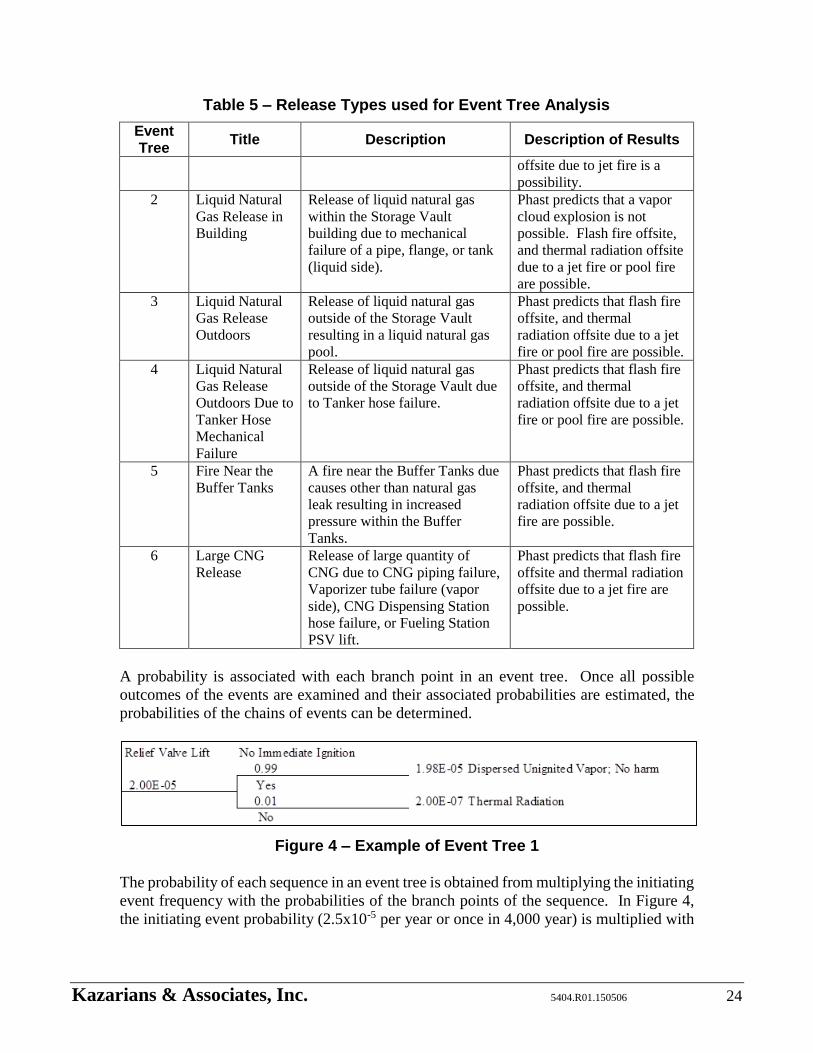
Kazarians & Associates, Inc. 5404.R01.150506 24
Table 5 – Release Types used for Event Tree Analysis
Event Tree
Title Description Description of Results
offsite due to jet fire is a
possibility.
2 Liquid Natural
Gas Release in
Building
Release of liquid natural gas
within the Storage Vault
building due to mechanical
failure of a pipe, flange, or tank
(liquid side).
Phast predicts that a vapor
cloud explosion is not
possible. Flash fire offsite,
and thermal radiation offsite
due to a jet fire or pool fire
are possible.
3 Liquid Natural
Gas Release
Outdoors
Release of liquid natural gas
outside of the Storage Vault
resulting in a liquid natural gas
pool.
Phast predicts that flash fire
offsite, and thermal
radiation offsite due to a jet
fire or pool fire are possible.
4 Liquid Natural
Gas Release
Outdoors Due to
Tanker Hose
Mechanical
Failure
Release of liquid natural gas
outside of the Storage Vault due
to Tanker hose failure.
Phast predicts that flash fire
offsite, and thermal
radiation offsite due to a jet
fire or pool fire are possible.
5 Fire Near the
Buffer Tanks
A fire near the Buffer Tanks due
causes other than natural gas
leak resulting in increased
pressure within the Buffer
Tanks.
Phast predicts that flash fire
offsite, and thermal
radiation offsite due to a jet
fire are possible.
6 Large CNG
Release
Release of large quantity of
CNG due to CNG piping failure,
Vaporizer tube failure (vapor
side), CNG Dispensing Station
hose failure, or Fueling Station
PSV lift.
Phast predicts that flash fire
offsite and thermal radiation
offsite due to a jet fire are
possible.
A probability is associated with each branch point in an event tree. Once all possible
outcomes of the events are examined and their associated probabilities are estimated, the
probabilities of the chains of events can be determined.
Figure 4 – Example of Event Tree 1
The probability of each sequence in an event tree is obtained from multiplying the initiating
event frequency with the probabilities of the branch points of the sequence. In Figure 4,
the initiating event probability (2.5x10⁻⁵ per year or once in 4,000 year) is multiplied with
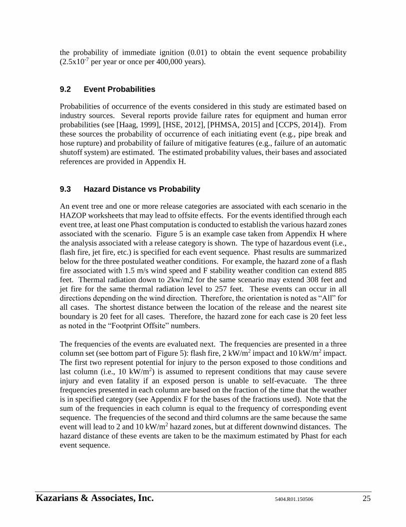
Kazarians & Associates, Inc. 5404.R01.150506 25
the probability of immediate ignition (0.01) to obtain the event sequence probability
(2.5x10⁻⁷ per year or once per 400,000 years).
9.2 Event Probabilities
Probabilities of occurrence of the events considered in this study are estimated based on
industry sources. Several reports provide failure rates for equipment and human error
probabilities (see [Haag, 1999], [HSE, 2012], [PHMSA, 2015] and [CCPS, 2014]). From
these sources the probability of occurrence of each initiating event (e.g., pipe break and
hose rupture) and probability of failure of mitigative features (e.g., failure of an automatic
shutoff system) are estimated. The estimated probability values, their bases and associated
references are provided in Appendix H.
9.3 Hazard Distance vs Probability
An event tree and one or more release categories are associated with each scenario in the
HAZOP worksheets that may lead to offsite effects. For the events identified through each
event tree, at least one Phast computation is conducted to establish the various hazard zones
associated with the scenario. Figure 5 is an example case taken from Appendix H where
the analysis associated with a release category is shown. The type of hazardous event (i.e.,
flash fire, jet fire, etc.) is specified for each event sequence. Phast results are summarized
below for the three postulated weather conditions. For example, the hazard zone of a flash
fire associated with 1.5 m/s wind speed and F stability weather condition can extend 885
feet. Thermal radiation down to 2kw/m2 for the same scenario may extend 308 feet and
jet fire for the same thermal radiation level to 257 feet. These events can occur in all
directions depending on the wind direction. Therefore, the orientation is noted as “All” for
all cases. The shortest distance between the location of the release and the nearest site
boundary is 20 feet for all cases. Therefore, the hazard zone for each case is 20 feet less
as noted in the “Footprint Offsite” numbers.
The frequencies of the events are evaluated next. The frequencies are presented in a three
column set (see bottom part of Figure 5): flash fire, 2 kW/m2 impact and 10 kW/m2 impact.
The first two represent potential for injury to the person exposed to those conditions and
last column (i.e., 10 kW/m2) is assumed to represent conditions that may cause severe
injury and even fatality if an exposed person is unable to self-evacuate. The three
frequencies presented in each column are based on the fraction of the time that the weather
is in specified category (see Appendix F for the bases of the fractions used). Note that the
sum of the frequencies in each column is equal to the frequency of corresponding event
sequence. The frequencies of the second and third columns are the same because the same
event will lead to 2 and 10 kW/m2 hazard zones, but at different downwind distances. The
hazard distance of these events are taken to be the maximum estimated by Phast for each
event sequence.

Kazarians & Associates, Inc. 5404.R01.150506 26
Figure 5 – Example of Hazard Distance vs Probabilities
The event tree analyses provide hazard distances and their probabilities of occurrence for
various scenarios. The scenarios are grouped into those that may cause an injury (i.e., flash
fire and 2kW/m2 exposure events) and may the potential to cause fatality (i.e., 10kW/m2
exposure events). A hazard distance versus probability of occurrence matrix can be put
together for these two cases by bringing together all scenarios. It is common practice to
present the probabilities of exceedance, which represent the probability of occurrence of
certain hazard distance or greater. For example, an event with a maximum impact 100 feet
downwind will also have an impact at 20 feet downwind, and so the probability of
exceedance at 20 feet will take into account the probabilities of all events with a maximum
impact of 20 feet or greater. Appendix H presents the results of the hazard distance vs.
probability calculations, which are based on the offsite footprint distances and probabilities
presented in Table H7 of Appendix H. The probability values in Appendix H are obtained
by adding probabilities that are computed using the event trees for all scenarios that lead
Kazarians & Associates, Inc. 5404.R01.150506 27
to a hazard distance equal or greater than the specified distance. For example, the
probability that a 10kW/m2 hazard zone will exceed beyond 170 feet from the facility
boundary is approximately once per 200,000 year (5x10⁻⁶ per year).
From the data presented in Appendix H it can be concluded that the overall probability of
experiencing an injurious event outside the facility boundaries is approximately once per
4,500 years and the probability of an event with the potential for a fatality offsite is
approximately once per 65,000 years. It is important to understand that these probability
values represent rare events that may never happen in the life of OmniTrans facility. One
method to interpret these values is to consider a large number of similar facilities. For
example, 2x10⁻⁴ per year (once in 5,000 years) can be interpreted as that there is a high
likelihood that the event may occur once within one year if 5,000 similar facilities exist.
Additionally, from the data in Appendix H, the following can be stated:
The hazard zone of 95% of events that may cause injury would not exceed 890 feet
from facility boundary.
The hazard zone of 95% of events that could be fatal would not exceed 180 feet
from facility boundary.
10.0 UNCERTAINTIES
Uncertainty is inherent to risk analysis. As it can be seen in the definition of risk (see
Section 4), one of the three parts that characterize risk deals with the likelihood of what
can wrong. These uncertainties are represented by the event probabilities discussed in the
preceding sections. Point values are used to express these probabilities. For example, in
Appendix H the probability of experiencing a 170 feet or greater hazard zone is 5 x 10⁻⁶
per year, a single value.
There are uncertainties inherent in all engineering computations. These uncertainties arise
from imperfect models of the events and imperfect statistical information. The following
notes address some of the sources of uncertainties that are deemed to be important to this
study.
Single values are used for the input parameters for Phast runs. For example, the
break size is specified as a 3” diameter opening on a hose 15 feet from the storage
tank and pressure behind that point as 80 psig. These single values represent a
range of possible parameter values.
The formulae that form the bases of Phast computations model very complex
physical phenomena in an idealized fashion. Much effort has been expended by
experts to make these computational methods as real as practically possible. But
there are still many uncertainties in these models that cannot be easily eliminated.
Kazarians & Associates, Inc. 5404.R01.150506 28
Two ignition possibilities are considered in this study – immediate and delayed
ignition. The delayed ignition is assumed to occur at the time when the vapor cloud
is at its largest extent downwind. In an actual event, ignition may occur at any time
after a release or not at all. This two-point model used in this study is a crude and
conservative depiction of what may occur in an actual event. It is deemed that this
practice is one of the significant sources of uncertainty in this study and the results
presented are larger than what they may have been if the ignition time was modeled
as a continuum between the point of release and largest cloud extent.
Probability values employed for estimating scenario occurrence probabilities
include uncertainties inherent in all statistical analyses. The values are taken from
industry sources that are based on general industry settings that cover a wide range
of design and application possibilities. These sources generally tend to over-
estimate the probability values due to the nature of risk analysis practices, where
the tendency is to over-estimate the risk to support a risk-averse approach. In some
cases the uncertainties in the probability values can be significant. However, in the
opinion of the analysts of this study, the probability values used are generally over-
estimated.
11.0 CONCLUSIONS AND RECOMMENDATIONS
A study is conducted of the LNG storage and handling systems of OmniTrans public transit
bus refueling station in the City of San Bernardino. The objectives of the study included:
Ensure compliance with safety and regulatory requirements.
Review of seismic aspects of the systems
An assessment of the probability of an explosive atmosphere
Identification of potential ignition sources
A quantitative analysis of accident scenarios that includes small releases
The probability and consequences of the explosion
Study whether a hazardous or non-hazardous area exists at the fueling site.
The codes and standards that apply to LNG fueling stations are reviewed. A large number
of standards were in effects when the original LNG storage, pumping and vaporization
systems were designed and constructed. Since then, they have been consolidated into
NFPA 52, which addresses LNG storage and fueling systems. In this study, the systems
are reviewed against the current requirements and it is concluded that in general terms the
systems comply with NFPA 52 requirements. There are only a few hardware related
differences between the design and current NPFA 52 requirements. The balance of the
differences relate to administrative issues that are partly met by current practices.

Kazarians & Associates, Inc. 5404.R01.150506 29
The seismic ruggedness of the systems is also reviewed in this study. The standard that
was used at the time of design is compared with current standards and it is concluded that
the margin of safety used in the original design well covers the new requirements.
Additionally, a system walk-down was conducted. From that direct observation of the
physical systems a few recommendations are proposed to improve seismic safety of the
storage and handling systems.
To address the last five bulleted items of the objective listed above, a risk analysis is
conducted where a set of potential release scenarios are identified. The hazard zone of
each scenario is estimated, and for those that can extend outside the facility boundary,
probability of occurrence is estimated. Scenarios are identified by using HAZOP
methodology (a method commonly used in the chemicals processing and petroleum
refining industries) and later refined through the application of event trees where various
potential conditions that can influence the hazard zone are included in the model. With
this methodology, a wide range of scenarios are identified that includes small and large
releases depending on the specific conditions of the event. For example, a flange failure is
expected to lead to a small release, while hose break when unloading a truck is expected to
lead to a large release.
Several computer programs were examined for estimating the shape and dimensions of
potential hazard zones. Phast [DNV, 2015] was selected for this study since it offers the
most sophisticated features that model release of LNG. Hazard zone computations take
into account release conditions (e.g., liquid release and evaporation), formation of a gas
cloud, and ignition leading to jet fire, pool fire and flash fire. The possibility of BLEVE
and vapor cloud explosion are examined, and it is concluded that neither pose a credible
threat at this facility. However, several scenarios are concluded to have an impact outside
the facility boundary through thermal radiation.
From these analyses it is concluded that an explosive atmosphere is only possible in
confined spaces. At this facility, the only confined space in which LNG may be released is
the Storage Vault, which is protected through explosion proof electrical equipment (i.e., all
ignition sources are fully isolated within the Vault) and a manually activated foam fire
protection system. As noted above, explosion is not credible in the open areas outside the
Vault.
Specific ignition sources are not examined explicitly in this study. It is assumed that
ignition is possible everywhere. Two ignition times are considered: immediate (i.e.,
ignition occurs upon release of LNG) and delayed (i.e., ignition occurs when the gas cloud
is at is maximum extent within the flammable range.) This leads to conservative results
because it does not take into account the possibility of ignition before maximum extent is
reached, which will predict a smaller hazard zone. It also does not take into account the
possibility of no ignition before the gas dissipates below its flammable concentration.
Scenario probabilities are also estimated in this study using failure probabilities and human
error rates provided in various industry sources. The hazard zones are divided into two
categories: (1) potential for injury and (2) severe injury with the possibility of fatality if

Kazarians & Associates, Inc. 5404.R01.150506 30
the exposed person is unable to self-evacuate. In the first category, flash fire scenarios and
hazard zones of 2kW/m2 thermal radiation are assumed to have the potential to cause an
injury. In the second category, 10kW/m2 thermal radiation is assumed to cause a condition
where, if an exposed person does not get an opportunity to self-evacuate (e.g., falls and
becomes incapacitated), a severe or even a fatal injury is possible. The total probabilities
of the two hazard categories are concluded to be once per 3,500 years and once per 47,000
years, respectively. These probabilities demonstrate that offsite impact of LNG operation
at OmniTrans facility is a rare event, which is also corroborated by the industry experience.
From a review of industry events since mid-1940s, none of the reported LNG release events
has adversely affected public safety. These probabilities are deemed to be conservative
given the uncertainties in the hazard zone modeling and that event probability sources tend
to report probability values conservatively.
From a study of scenario probabilities and hazard zones it is concluded that 95% of
potential injury scenarios may extend up to 880 feet from the facility boundary and 95%
scenarios with the potential for severe injury may extend up to 175 feet from the facility
boundary.
As a final conclusion, it can be stated that there is no regulatory requirement for OmniTrans
to modify any of its current practices, and that this study did not discover any significant
safety deficiencies. However, based on direct inspection of the physical systems,
observations of LNG receiving operations, review of current OmniTrans practices and
review of current codes and standards, a list of recommendations are put together as
potential improvement suggestions for the consideration of OmniTrans management. The
recommendations are listed in Table 6 bellow.
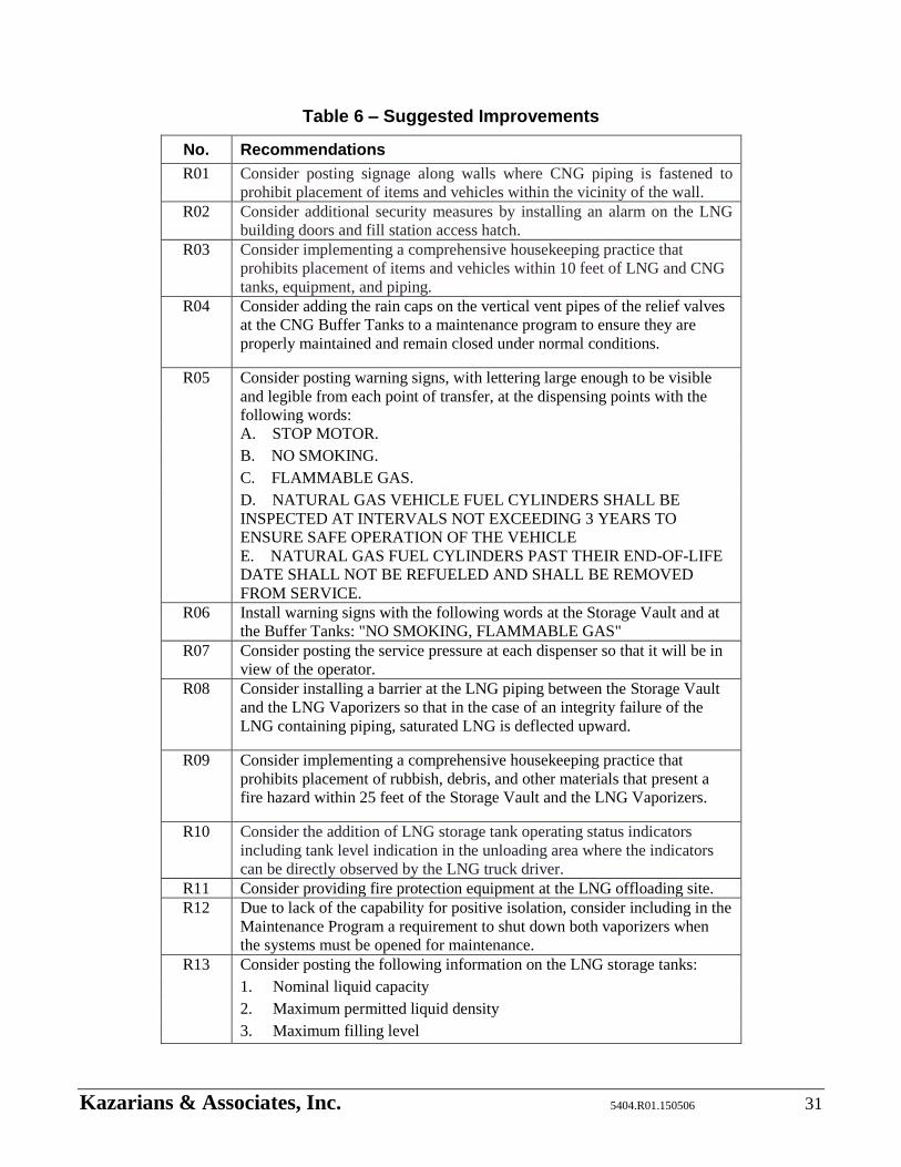
Kazarians & Associates, Inc. 5404.R01.150506 31
Table 6 – Suggested Improvements
No. Recommendations
R01 Consider posting signage along walls where CNG piping is fastened to
prohibit placement of items and vehicles within the vicinity of the wall.
R02 Consider additional security measures by installing an alarm on the LNG
building doors and fill station access hatch.
R03 Consider implementing a comprehensive housekeeping practice that
prohibits placement of items and vehicles within 10 feet of LNG and CNG
tanks, equipment, and piping.
R04 Consider adding the rain caps on the vertical vent pipes of the relief valves
at the CNG Buffer Tanks to a maintenance program to ensure they are
properly maintained and remain closed under normal conditions.
R05 Consider posting warning signs, with lettering large enough to be visible
and legible from each point of transfer, at the dispensing points with the
following words:
A. STOP MOTOR.
B. NO SMOKING.
C. FLAMMABLE GAS.
D. NATURAL GAS VEHICLE FUEL CYLINDERS SHALL BE
INSPECTED AT INTERVALS NOT EXCEEDING 3 YEARS TO
ENSURE SAFE OPERATION OF THE VEHICLE
E. NATURAL GAS FUEL CYLINDERS PAST THEIR END-OF-LIFE
DATE SHALL NOT BE REFUELED AND SHALL BE REMOVED
FROM SERVICE.
R06 Install warning signs with the following words at the Storage Vault and at
the Buffer Tanks: "NO SMOKING, FLAMMABLE GAS"
R07 Consider posting the service pressure at each dispenser so that it will be in
view of the operator.
R08 Consider installing a barrier at the LNG piping between the Storage Vault
and the LNG Vaporizers so that in the case of an integrity failure of the
LNG containing piping, saturated LNG is deflected upward.
R09 Consider implementing a comprehensive housekeeping practice that
prohibits placement of rubbish, debris, and other materials that present a
fire hazard within 25 feet of the Storage Vault and the LNG Vaporizers.
R10 Consider the addition of LNG storage tank operating status indicators
including tank level indication in the unloading area where the indicators
can be directly observed by the LNG truck driver.
R11 Consider providing fire protection equipment at the LNG offloading site.
R12 Due to lack of the capability for positive isolation, consider including in the
Maintenance Program a requirement to shut down both vaporizers when
the systems must be opened for maintenance.
R13 Consider posting the following information on the LNG storage tanks:
1. Nominal liquid capacity
2. Maximum permitted liquid density
3. Maximum filling level
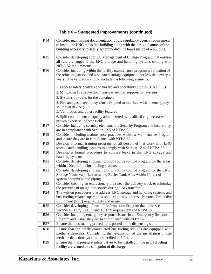
Kazarians & Associates, Inc. 5404.R01.150506 32
Table 6 – Suggested Improvements (continued)
R14 Consider maintaining documentation of the regulatory agency requirement
to install the LNG tanks in a building along with the design features of the
building necessary to safely accommodate the tanks inside of a building.
R15 Consider developing a formal Management of Change Program that ensures
all future changes to the LNG storage and handling systems comply with
NFPA 52 requirements.
R16 Consider including within the facility maintenance program a validation of
the refueling station and associated storage equipment not less than every 4
years. The validation should include the following elements:
1. Process safety analysis and hazard and operability studies (HAZOPS)
2. Mitigating fire protection measures such as suppression systems
3. Systems or vaults for the containers
4. Fire and gas detection systems designed to interface with an emergency
shutdown device (ESD)
5. Ventilation and other facility features
6. Spill containment adequacy administered by qualified engineer(s) with
proven expertise in these fields
R17 Consider including security elements in a Security Program and insure they
are in compliance with Section 12.5 of NFPA 52.
R18 Consider including maintenance practices within a Maintenance Program
and insure they are in compliance with NFPA 52.
R19 Develop a formal training program for all personnel that work with LNG
storage and handling systems to comply with Section 12.4 of NFPA 52.
R20 Develop a formal procedure to address leaks in the LNG storage and
handling systems.
R21 Consider developing a formal ignition source control program for the areas
within 10feet of the bus fueling stations.
R22 Consider developing a formal ignition source control program for the LNG
Storage Vault, vaporizer area and Buffer Tank Area within 10 feet of
system equipment and piping.
R23 Consider creating an exclusionary area near the delivery truck to minimize
the presence of an ignition source during LNG transfer.
R24 The written procedures that address LNG storage and handling systems and
bus fueling related operations shall explicitly address Personal Protective
Equipment (PPE) requirements and usage.
R25 Consider developing a formal Fire Protection Program that addresses
Section 10.13.7, 10.13.8 and 10.13.9 requirements of NFPA 52.
R26 Consider including emergency response issues in an Emergency Response
Program and insure they are in compliance with NFPA 52.
R27 Ensure that bus fueling procedure is posted at the dispensing station.
R28 Ensure that the newly constructed bus fueling stations are equipped with
methane detectors. Consider further evaluation of the installation of site
methane detection systems as specified in 5.2.1.1.1
R29 Ensure that the pressure safety valves to be installed in the new refueling
facility are vented to a safe point of discharge.
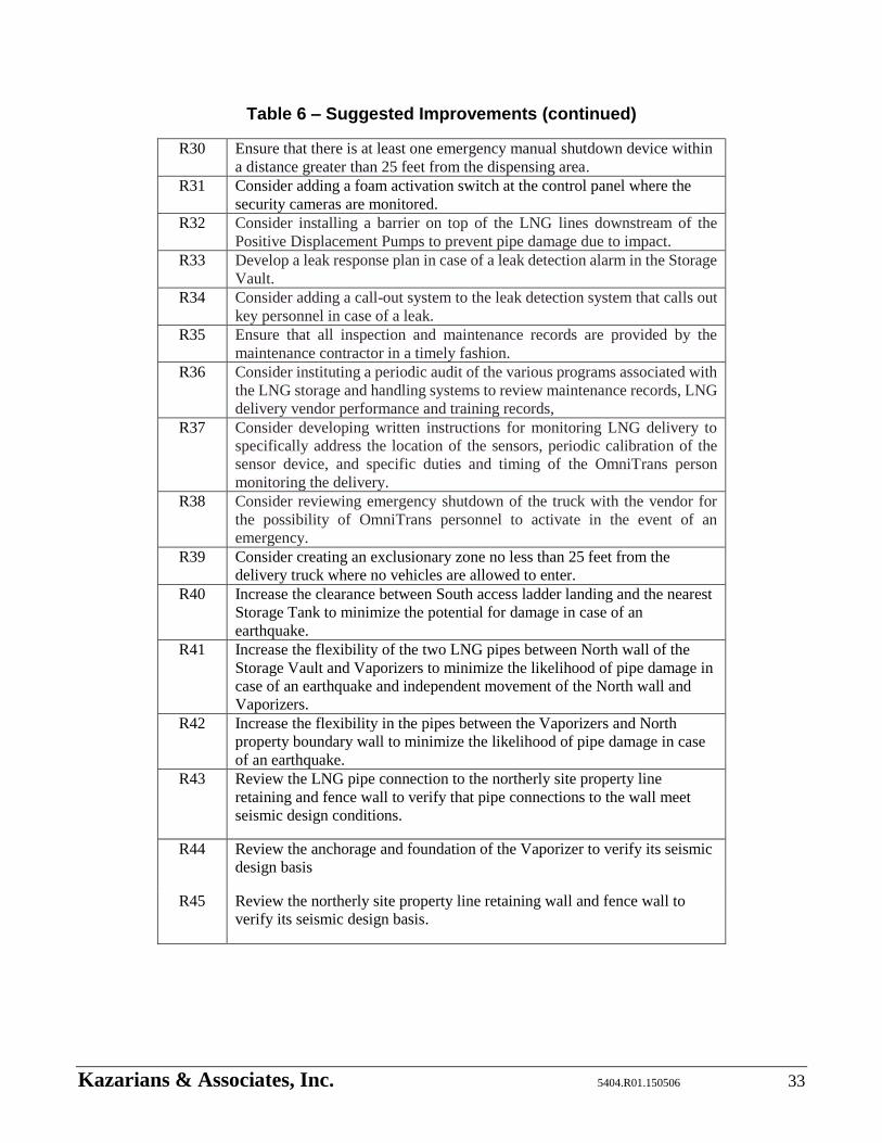
Kazarians & Associates, Inc. 5404.R01.150506 33
Table 6 – Suggested Improvements (continued)
R30 Ensure that there is at least one emergency manual shutdown device within
a distance greater than 25 feet from the dispensing area.
R31 Consider adding a foam activation switch at the control panel where the
security cameras are monitored.
R32 Consider installing a barrier on top of the LNG lines downstream of the
Positive Displacement Pumps to prevent pipe damage due to impact.
R33 Develop a leak response plan in case of a leak detection alarm in the Storage
Vault.
R34 Consider adding a call-out system to the leak detection system that calls out
key personnel in case of a leak.
R35 Ensure that all inspection and maintenance records are provided by the
maintenance contractor in a timely fashion.
R36 Consider instituting a periodic audit of the various programs associated with
the LNG storage and handling systems to review maintenance records, LNG
delivery vendor performance and training records,
R37 Consider developing written instructions for monitoring LNG delivery to
specifically address the location of the sensors, periodic calibration of the
sensor device, and specific duties and timing of the OmniTrans person
monitoring the delivery.
R38 Consider reviewing emergency shutdown of the truck with the vendor for
the possibility of OmniTrans personnel to activate in the event of an
emergency.
R39 Consider creating an exclusionary zone no less than 25 feet from the
delivery truck where no vehicles are allowed to enter.
R40 Increase the clearance between South access ladder landing and the nearest
Storage Tank to minimize the potential for damage in case of an
earthquake.
R41 Increase the flexibility of the two LNG pipes between North wall of the
Storage Vault and Vaporizers to minimize the likelihood of pipe damage in
case of an earthquake and independent movement of the North wall and
Vaporizers.
R42 Increase the flexibility in the pipes between the Vaporizers and North
property boundary wall to minimize the likelihood of pipe damage in case
of an earthquake.
R43 Review the LNG pipe connection to the northerly site property line
retaining and fence wall to verify that pipe connections to the wall meet
seismic design conditions.
R44 Review the anchorage and foundation of the Vaporizer to verify its seismic
design basis
R45 Review the northerly site property line retaining wall and fence wall to
verify its seismic design basis.

Kazarians & Associates, Inc. 5404.R01.150506 34
12.0 REFERENCES
ASCE, 2013 “Minimum Design Loads for Buildings and Other Structures (ASCE/SEI 7-
10)”, 3rd Edition. American Society of Civil Engineers. 2013.
Byerly, 1989 Byerly, John R. “Geotechnical Investigation, Additions to OmniTrans Metro
Facility, 5th Street and Medical Center Drive” February 7, 1989.
Canvey, 1981 “A Second Report: A Review of Potential Hazards from Operations in the
Canvey island/Thurrock Area Three Years after Publication of The Convey
Report,” Health and Safety Executive, Canvey, 1981.
CBC, 2010 “2010 California Building Code”, California Building Standards
Commission, California Code of Regulations, Title 24, Part 2, Volumes 1
and 2. 2010.
CBC, 2013 “2013 California Building Code”, California Building Standards
Commission, California Code of Regulations, Title 24, Part 2, Volumes 1
and 2. 2013.
CCPS, 1989 “Guidelines for Chemical Process Quantitative Risk Analysis”, published
by the Center for Chemical Process Safety of the American Institute of
Chemical Engineers, 1989.
CCPS, 2008 “Guidelines for Hazard Evaluation Procedures”, published by the Center for
Chemical Process Safety of the American Institute of Chemical Engineers,
3rd Edition, April 2008.
CCPS, 2013 “Guidelines for Enabling Conditions and Conditional Modifiers in Layer of
Protection Analysis,” Center for Chemical Process Safety, 2013.
CCPS, 2014 “Guidelines for Initiating Events and Independent Protection Layers in Layer
of Protection Analysis,” Center for Chemical Process Safety, 2014.
DNV, 2015 Phast Modeling Software, version 7.11.33.0. DNV GL AS.
EPA, 2015 "Risk Management Programs for Chemical Accidental Release
Prevention", Federal EPA, 40 CFR Part 68.
Gulliver, 2015 “A Crash Course in Probability,” Economist, Gulliver, Business Travel,
January 20, 2015.
Haag, 1999 “Guidelines for Quantitative Risk Assessment,” Committee for Prevention of
Disasters by Hazardous Materials, Netherlands, CPR 18E, Haag and Ale,
1999.
Kazarians & Associates, Inc. 5404.R01.150506 35
HSE, 2012. “Failure Rate and Event Data for use within Risk Assessments,” Health and
Safety Executive, June 28, 2012.
IBC, 2012 “2012 International Building Code”, International Code Council, Inc. 2011.
Kaplan, 1981 Kaplan, S. and B. John Garrick “On the Quantitative Definition of Risk”,
Risk Analysis, vol. 1, pp.11-27, 1981.
Loss Control, 2001 “PHA Worksheet, OmniTrans East Valley LNG – CNG Facility”,
Loss Control Associates, Inc. August 22, 2001.
Ninyo, 1997 “Geotechnical and Environmental Consulting Services East Valley
Maintenance Facility 1700 West Fifth Street San Bernardino, California”,
Ninyo & Moore Geotechnical and Environmental Sciences Consultants,
Project No. 200932-01. January 13, 1997.
NFPA 2 “NFPA® 2 – Hydrogen Technologies Code”, National Fire Protection
Association. 2011 Edition. Quincy, MA. 2011.
NFPA 52 “NFPA® 52 – Vehicular Gaseous Fuel Systems Code”, National Fire
Protection Association. 2013 Edition. Quincy, MA. 2013.
NFPA 55 “NFPA® 55 – Compressed Gases and Cryogenic Fluids Code”, National
Fire Protection Association. 2013 Edition. Quincy, MA. 2013.
NFPA 59A “NFPA® 59A – Standard for the Production, Storage, and Handling of
Liquefied Natural Gas (LNG)”, National Fire Protection Association. 2013
Edition. Quincy, MA. 2013.
OSHSB, 2005 Rank, Steven L. “In the Matter of an Application for a Permanent Variance
by: OmniTrans 1700 West Fifth Street San Bernardino, CA 92411”,
Occupational Safety and Health Standards Board. OSHSB File No. 04-V-
037. May 19, 2005
PHA, 2001 “OmniTrans East Valley LNG – CNG Facility, San Bernardino, CA August
21 & 22, 2001”, Process Hazard Analysis. Loss Control Associates, Inc. 2001.
PHMSA, 2015 “Nominal Failure Rate Table 1,” U.S. Department of Transportation
Pipelines and Hazardous Materials Safety Administration, February 11,
2015.
Pitblado, 2006 “Potential for BLEVE associated with marine LNG vessel fires,” Robin
Pitblado, Journal of Hazardous Materials, October 13, 2006.
Quarterman, 2011 Quarterman, Cynthia L. Final Decision. In the Matter of Det Norske
Veritas (USA), Inc., Respondent. PHMSA Docket No. 2011-0075. U.S.

Kazarians & Associates, Inc. 5404.R01.150506 36
Department of Transportation Pipeline and Hazardous Materials Safety
Administration. October 7, 2011.
Quest, 1999 “A Comparison of Vapor Cloud Explosion Models.” The Quest Quarterly
Volume 4, Issue 1 (Spring 1999): PDF.
Shaba, 2013 Shaba, Kehinde. PhastTM - Effectively Meeting the LNG Hazard
Management Challenge. DNV Software. March 2013.
Taveau, 2012 Taveau, Jérôme. “The Buncefield Explosion: Were the Resulting
Overpressures Really Unforeseeable?” Process Safety Progress Volume 31,
No. (March 2012): PDF.
UBC, 1997 “1997 Uniform Building Code”, International Conference of Building
Officials, April 1997.
Witlox, 2015 Witlox, Henk W.M., Mike Harper, and Robin Pitblado. Validation of Phast
Dispersion Model as Required for USA LNG Siting Applications. DNV
Software, London, UK, and DNV Houston, Texas, USA, 2015.
Xu, 2014 Xu, Y. Indoor Dispersion. DNV GL - Software. August 2014.
Xu, 2014(a) Xu, Y. Obstructed Region Explosion Model. DNV GL - Software. August
2014.
Appendix A – Properties of Natural Gas
Kazarians & Associates, Inc. 5404.R01.150504 A-1
APPENDIX A – PROPERTIES OF NATURAL GAS
A.1 PHYSICAL PROPERTIES OF NATURAL GAS
Natural Gas is a term used to refer to a mixture of hydrocarbon components that is typically obtained from oil-wells. It consists primarily of methane. Minor components of natural gas include ethane, propane, butane, pentane, nitrogen, and other trace components. The composition of natural gas can vary significantly, depending on the source. Table A-1 contains the typical composition percentages for the constituent components of natural gas as presented by the UnionGas [Reference A-1]. Table A-1 also contains the makeup of the natural gas used at the OmniTrans Facility, as specified in the contract with Clean Energy. This is the composition which is used in the analysis.
Table A-1 - Typical Composition Ranges of Natural Gas Components
Component Typical Composition
Range (mole %) OmniTrans LNG
Composition (mole %)Methane 87.0-96.0 98.0 Ethane 1.8-5.1 1.0 Propane 0.1-1.5 0.2 Butane 0.02-0.6 0.2 Pentane Trace-0.18 0.1
Hexane + Trace - 0.06 Trace Nitrogen 1.3-5.6 0.5
Carbon Dioxide 0.1-1.0 Trace Oxygen 0.01-0.1 Trace
Hydrogen Trace-0.02 Trace Due to its high methane content, natural gas exists as a vapor at ambient conditions. Its boiling point is approximately -260°F. In order to maintain natural gas as Liquefied Natural Gas (LNG), it must be subjected to either very high pressure or very low temperature. When released into the atmosphere, LNG will vaporize rapidly by absorbing heat from its surroundings. In this study, where LNG specific data could not be obtained, the properties of methane are used instead. Table A-2 presents physical property data for methane taken from Reference A-2. Values for the specific heats were taken from the Air Liquide data sheet for methane [Reference A-3]. At ambient temperature, natural gas vapor is less dense than air, causing warm natural gas to rise rapidly when released into the atmosphere. At the low temperatures required to form LNG, however, the density of evolving vapor will be greater than that of the ambient air. Therefore, LNG pools will form a dense vapor cloud, which stays close to the ground until the vapor warms enough to become less dense than air (which occurs at approximately -180°F).
Kazarians & Associates, Inc. 5404.R01.150504 A-2
Table A-2 - Physical Properties of Methane
Name Methane
Formula CH4
Molecular Weight (g/mol) 16.043 g/mol
Boiling Point at 1 atm (°F) -258.68
Liquid Density at -260°F and 14.7 psia (g/mL) 0.42
Specific Gravity at 77°F and 1 atm 0.55
Heat Capacity at Constant Pressure (CP) at atmospheric Temperature and Pressure (kJ/mol K)
0.0358
Heat Capacity at Constant Volume (CV) at atmospheric Temperature and Pressure (kJ/mol K)
0.0274
Heat of Vaporization (kJ/kg) 510.83
At ambient temperature, liquid natural gas will expand up to 600 times its initial volume upon vaporization. A.2 HAZARDS OF NATURAL GAS
Natural gas is a flammable substance. When released into the atmosphere, it has the potential to form a vapor cloud, which may combust if it comes into contact with an ignition source. In order for ignition to occur, the concentration of flammable material in contact with the ignition source must be within a specific range. Outside the bounds of this range, it is either too rich or too lean for combustion to occur. The bounds of this range are termed as the lower flammable limit (LFL) and as upper flammable limit (UFL). For natural gas, the flammable range is 5% to 15% by volume according to Reference A-1. Additionally, the low temperatures required to maintain natural gas in its liquid state present an additional hazard of exposure to cryogenic material. Such exposure can lead to frostbite and possible permanent tissue damage. Natural gas vapor can be an asphyxiation hazard if personnel are trapped within a concentrated vapor cloud. The dense cloud resulting from a release of LNG in a congested area could lead to asphyxiation if operators are unable to quickly evacuate the area.
Kazarians & Associates, Inc. 5404.R01.150504 A-3
A.3 COMBUSTION PROPERTIES OF NATURAL GAS
Combustion Characteristics of Natural Gas Table A-3 presents typical combustion data for natural gas as provided by UnionGas [Reference A-1].
Table A-3 - Combustion Properties of Natural Gas
Name Value
Autoignition Temperature (°F) 1,099
Flammability Range in air (%volume) 5 to 15
Flame Temperature (°F) 3,562
Heating Value Lower Heating Value (LHV) is a measure of the amount of heat released (per unit mass or volume) when a fuel is burned at a specific reference temperature and pressure. Fuels with a larger LHV provide more heat per unit of fuel than those with a small LHV. According to the Department of Energy [Reference A-4], natural gas has an approximate LHV of 20,267 Btu/lb. Higher Heating Value (HHV) is a second measure of a fuel’s heating, and is closely related to LHV. HHV is a measure of the heat produced from the reaction used to determine the LHV, plus the heat produced when the resultant water vapor is condensed. The HHV for natural gas is approximately 22,453 Btu/lb. The difference between HHV and LHV is largely dependent on the amount of hydrogen present in the fuel source. Fuels with higher hydrogen content will form greater amounts of water vapor during combustion, which results in a larger difference in heating value. A.4 REFERENCES
A-1. Chemical Composition of Natural Gas. UnionGas. Retrieved January 29, 2015 from http://www.uniongas.com/about-us/about-natural-gas/Chemical-Composition-of-Natural-Gas.
A-2. Gallant, RW., and Carl L. Yaws. Physical Properties of Hydrocarbons. Volume 1. 2nd ed.
Houston, Texas: Gulf Publishing Company, 1992. A-3. Gas Encyclopedia. Air Liquide. Retrieved February 23, 2015 from
http://encyclopedia.airliquide.com/Encyclopedia.asp?GasID=41#GeneralData. A-4. Boundy, Bob, et al. Biomass Energy Data Book. 4th ed. US Department of Energy, 2011.

Appendix B - Compliance with NFPA 52 Requirements
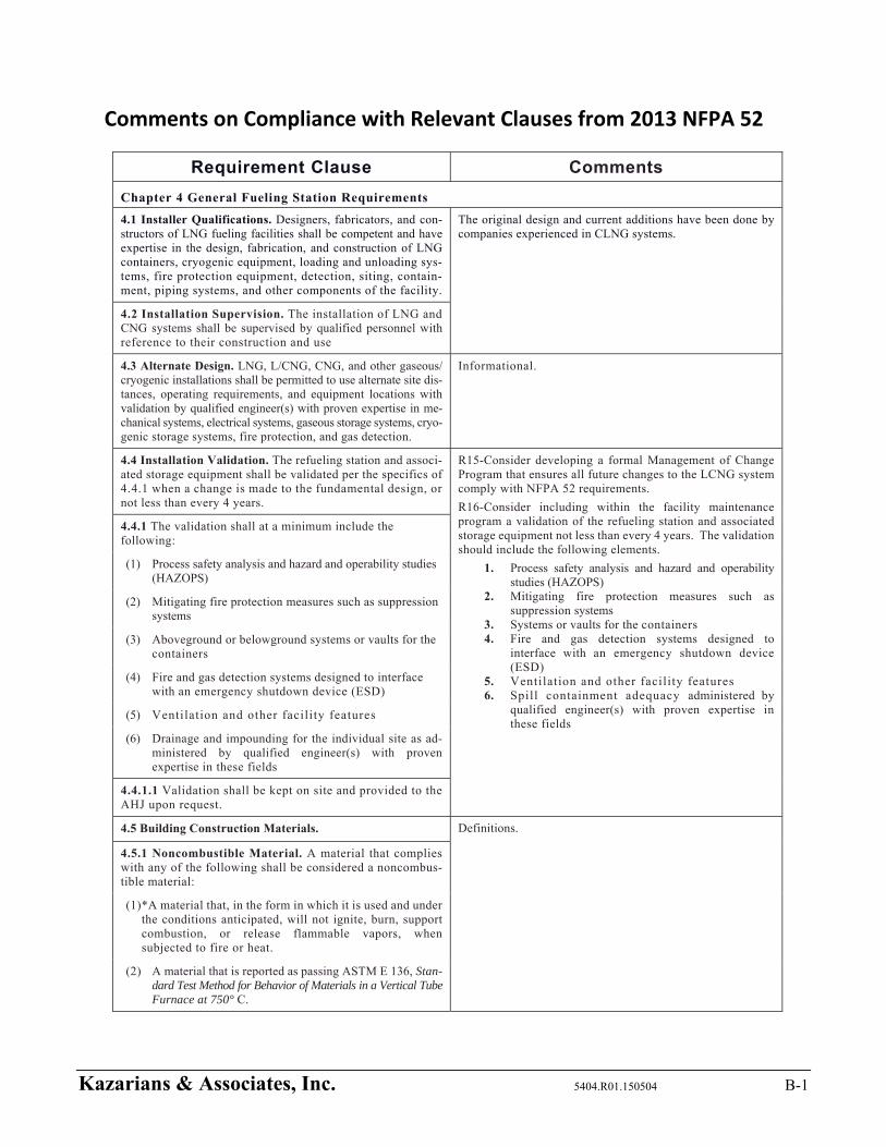
Kazarians & Associates, Inc. 5404.R01.150504 B-1
Comments on Compliance with Relevant Clauses from 2013 NFPA 52
Requirement Clause Comments
Chapter 4 General Fueling Station Requirements
4.1 Installer Qualifications. Designers, fabricators, and con-structors of LNG fueling facilities shall be competent and have expertise in the design, fabrication, and construction of LNG containers, cryogenic equipment, loading and unloading sys-tems, fire protection equipment, detection, siting, contain-ment, piping systems, and other components of the facility.
The original design and current additions have been done by companies experienced in CLNG systems.
4.2 Installation Supervision. The installation of LNG and CNG systems shall be supervised by qualified personnel with reference to their construction and use
4.3 Alternate Design. LNG, L/CNG, CNG, and other gaseous/ cryogenic installations shall be permitted to use alternate site dis-tances, operating requirements, and equipment locations with validation by qualified engineer(s) with proven expertise in me-chanical systems, electrical systems, gaseous storage systems, cryo-genic storage systems, fire protection, and gas detection.
Informational.
4.4 Installation Validation. The refueling station and associ-ated storage equipment shall be validated per the specifics of 4.4.1 when a change is made to the fundamental design, or not less than every 4 years.
R15-Consider developing a formal Management of Change Program that ensures all future changes to the LCNG system comply with NFPA 52 requirements.
R16-Consider including within the facility maintenance program a validation of the refueling station and associated storage equipment not less than every 4 years. The validation should include the following elements.
1. Process safety analysis and hazard and operability studies (HAZOPS)
2. Mitigating fire protection measures such as suppression systems
3. Systems or vaults for the containers 4. Fire and gas detection systems designed to
interface with an emergency shutdown device (ESD)
5. Ventilation and other facility features 6. Spill containment adequacy administered by
qualified engineer(s) with proven expertise in these fields
4.4.1 The validation shall at a minimum include the following:
(1) Process safety analysis and hazard and operability studies (HAZOPS)
(2) Mitigating fire protection measures such as suppression systems
(3) Aboveground or belowground systems or vaults for the containers
(4) Fire and gas detection systems designed to interface with an emergency shutdown device (ESD)
(5) Ventilation and other facility features
(6) Drainage and impounding for the individual site as ad-ministered by qualified engineer(s) with proven expertise in these fields
4.4.1.1 Validation shall be kept on site and provided to the AHJ upon request.
4.5 Building Construction Materials. Definitions.
4.5.1 Noncombustible Material. A material that complies with any of the following shall be considered a noncombus-tible material:
(1) *A material that, in the form in which it is used and under the conditions anticipated, will not ignite, burn, support combustion, or release flammable vapors, when subjected to fire or heat.
(2) A material that is reported as passing ASTM E 136, Stan-dard Test Method for Behavior of Materials in a Vertical Tube Furnace at 750° C.
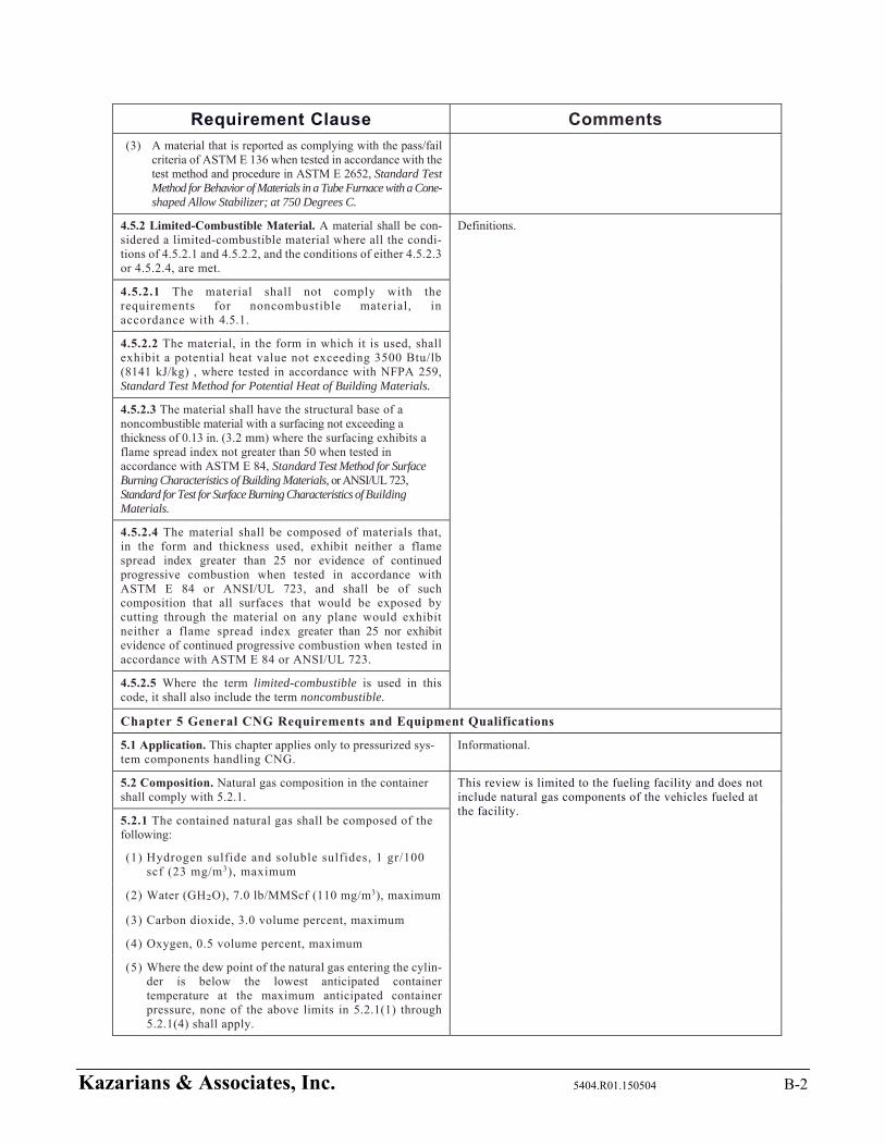
Kazarians & Associates, Inc. 5404.R01.150504 B-2
Requirement Clause Comments
(3) A material that is reported as complying with the pass/fail criteria of ASTM E 136 when tested in accordance with the test method and procedure in ASTM E 2652, Standard Test Method for Behavior of Materials in a Tube Furnace with a Cone-shaped Allow Stabilizer; at 750 Degrees C.
4.5.2 Limited-Combustible Material. A material shall be con-sidered a limited-combustible material where all the condi-tions of 4.5.2.1 and 4.5.2.2, and the conditions of either 4.5.2.3 or 4.5.2.4, are met.
Definitions.
4.5.2.1 The material shall not comply with the requirements for noncombustible material, in accordance with 4.5.1.
4.5.2.2 The material, in the form in which it is used, shall exhibit a potential heat value not exceeding 3500 Btu/lb (8141 kJ/kg) , where tested in accordance with NFPA 259, Standard Test Method for Potential Heat of Building Materials.
4.5.2.3 The material shall have the structural base of a noncombustible material with a surfacing not exceeding a thickness of 0.13 in. (3.2 mm) where the surfacing exhibits a flame spread index not greater than 50 when tested in accordance with ASTM E 84, Standard Test Method for Surface Burning Characteristics of Building Materials, or ANSI/UL 723, Standard for Test for Surface Burning Characteristics of Building Materials.
4.5.2.4 The material shall be composed of materials that, in the form and thickness used, exhibit neither a flame spread index greater than 25 nor evidence of continued progressive combustion when tested in accordance with ASTM E 84 or ANSI/UL 723, and shall be of such composition that all surfaces that would be exposed by cutting through the material on any plane would exhibit neither a flame spread index greater than 25 nor exhibit evidence of continued progressive combustion when tested in accordance with ASTM E 84 or ANSI/UL 723.
4.5.2.5 Where the term limited-combustible is used in this code, it shall also include the term noncombustible.
Chapter 5 General CNG Requirements and Equipment Qualifications
5.1 Application. This chapter applies only to pressurized sys-tem components handling CNG.
Informational.
5.2 Composition. Natural gas composition in the container shall comply with 5.2.1.
This review is limited to the fueling facility and does not include natural gas components of the vehicles fueled at the facility.
5.2.1 The contained natural gas shall be composed of the following:
(1) Hydrogen sulfide and soluble sulfides, 1 gr/100 scf (23 mg/m3), maximum
(2) Water (GH2O), 7.0 lb/MMScf (110 mg/m3), maximum
(3) Carbon dioxide, 3.0 volume percent, maximum
(4) Oxygen, 0.5 volume percent, maximum
(5) Where the dew point of the natural gas entering the cylin-der is below the lowest anticipated container temperature at the maximum anticipated container pressure, none of the above limits in 5.2.1(1) through 5.2.1(4) shall apply.
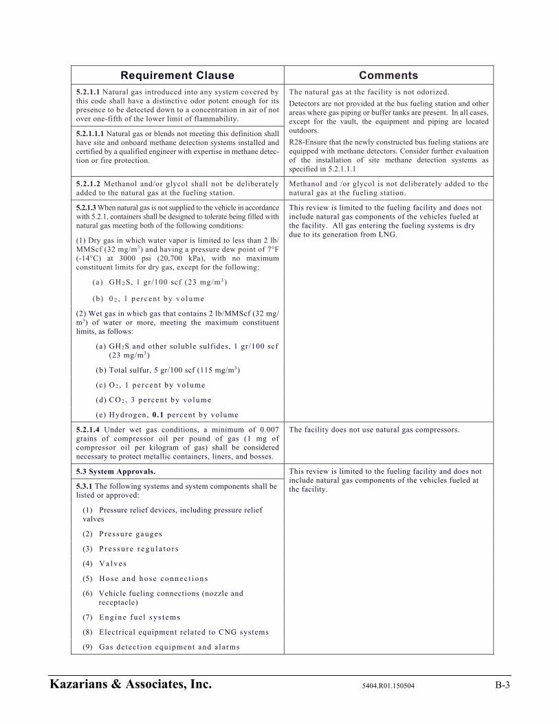
Kazarians & Associates, Inc. 5404.R01.150504 B-3
Requirement Clause Comments
5.2.1.1 Natural gas introduced into any system covered by this code shall have a distinctive odor potent enough for its presence to be detected down to a concentration in air of not over one-fifth of the lower limit of flammability.
The natural gas at the facility is not odorized.
Detectors are not provided at the bus fueling station and other areas where gas piping or buffer tanks are present. In all cases, except for the vault, the equipment and piping are located outdoors.
R28-Ensure that the newly constructed bus fueling stations are equipped with methane detectors. Consider further evaluation of the installation of site methane detection systems as specified in 5.2.1.1.1
5.2.1.1.1 Natural gas or blends not meeting this definition shall have site and onboard methane detection systems installed and certified by a qualified engineer with expertise in methane detec-tion or fire protection.
5.2.1.2 Methanol and/or glycol shall not be deliberately added to the natural gas at the fueling station.
Methanol and /or glycol is not deliberately added to the natural gas at the fueling station.
5.2.1.3 When natural gas is not supplied to the vehicle in accordance with 5.2.1, containers shall be designed to tolerate being filled with natural gas meeting both of the following conditions:
This review is limited to the fueling facility and does not include natural gas components of the vehicles fueled at the facility. All gas entering the fueling systems is dry due to its generation from LNG.
(1) Dry gas in which water vapor is limited to less than 2 lb/ MMScf (32 mg/m3) and having a pressure dew point of 7°F (-14°C) at 3000 psi (20,700 kPa), with no maximum constituent limits for dry gas, except for the following:
(a) GH2S, 1 gr/100 scf (23 mg/m3)
(b) 0 2 , 1 pe rcen t by vo lume
(2) Wet gas in which gas that contains 2 lb/MMScf (32 mg/ m3) of water or more, meeting the maximum constituent limits, as follows:
(a) GH2S and other soluble sulfides, 1 gr/100 scf (23 mg/m3)
(b) Total sulfur, 5 gr/100 scf (115 mg/m3)
(c) O 2 , 1 pe rcen t by vo lume
(d) CO 2 , 3 pe rcen t by vo lume
(e) Hydrogen, 0.1 percent by volume
5.2.1.4 Under wet gas conditions, a minimum of 0.007 grains of compressor oil per pound of gas (1 mg of compressor oil per kilogram of gas) shall be considered necessary to protect metallic containers, liners, and bosses.
The facility does not use natural gas compressors.
5.3 System Approvals. This review is limited to the fueling facility and does not include natural gas components of the vehicles fueled at the facility. 5.3.1 The following systems and system components shall be
listed or approved:
(1) Pressure relief devices, including pressure relief valves
(2) Pressu re gauges
(3) P r e s s u r e r e g u l a t o r s
(4) V a l v e s
(5) H o s e a n d h o s e c o n n e c t i o n s
(6) Vehicle fueling connections (nozzle and receptacle)
(7) E n g i n e fu e l s y s t e m s
(8) Electrical equipment related to CNG systems
(9) Gas detect ion equipment and a larms
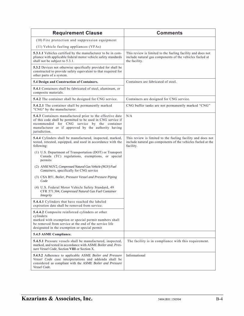
Kazarians & Associates, Inc. 5404.R01.150504 B-4
Requirement Clause Comments
(10) Fire pro tec t ion and suppress ion equipment
(11) Vehicle fuel ing appliances (VFAs)
5.3.1.1 Vehicles certified by the manufacturer to be in com-pliance with applicable federal motor vehicle safety standards shall not be subject to 5.3.1.
This review is limited to the fueling facility and does not include natural gas components of the vehicles fueled at the facility.
5.3.2 Devices not otherwise specifically provided for shall be constructed to provide safety equivalent to that required for other parts of a system.
5.4 Design and Construction of Containers. Containers are fabricated of steel.
5.4.1 Containers shall be fabricated of steel, aluminum, or composite materials.
5.4.2 The container shall be designed for CNG service. Containers are designed for CNG service.
5.4.2.1 The container shall be permanently marked "CNG" by the manufacturer.
CNG buffer tanks are not permanently marked “CNG”
5.4.3 Containers manufactured prior to the effective date of this code shall be permitted to be used in CNG service if recommended for CNG service by the container manufacturer or if approved by the authority having jurisdiction.
N/A
5.4.4 Cylinders shall be manufactured, inspected, marked, tested, retested, equipped, and used in accordance with the following:
This review is limited to the fueling facility and does not include natural gas components of the vehicles fueled at the facility.
(1) U.S. Department of Transportation (DOT) or Transport Canada (TC) regulations, exemptions, or special permits
(2) ANSI NGV2, Compressed Natural Gas Vehicle (NGV) Fuel Containers, specifically for CNG service
(3) CSA B51, Boiler, Pressure Vessel and Pressure Piping Code
(4) U.S. Federal Motor Vehicle Safety Standard, 49 CFR 571.304, Compressed Natural Gas Fuel Container Integrity
5.4.4.1 Cylinders that have reached the labeled expiration date shall be removed from service.
5.4.4.2 Composite reinforced cylinders or other cylinders marked with exemption or special permit numbers shall be removed from service at the end of the service life designated in the exemption or special permit
5.4.5 ASME Compliance.
5.4.5.1 Pressure vessels shall be manufactured, inspected, marked, and tested in accordance with ASME Boiler and. Pres-sure Vessel Code, Section VIII or Section X.
The facility is in compliance with this requirement.
5.4.5.2 Adherence to applicable ASME Boiler and Pressure Vessel Code case interpretations and addenda shall be considered as compliant with the ASME Boiler and Pressure Vessel Code.
Informational
Kazarians & Associates, Inc. 5404.R01.150504 B-5
Requirement Clause Comments
5.4.5.3 Pressure vessels manufactured to the requirements of the ASME Boiler and Pressure Vessel Code shall be registered with the National Board of Boiler and Pressure Vessel Inspectors.
CNG buffer tanks are permanently marked with a National Board registration number.
5.4.6 The + (plus) and * (star) markings on DOT and TC cylinders shall not apply in accordance with DOT and TC regulations for cylinders for flammable compressed gases.
Informational.
5.4.6.1 The star marking shall be removed or obliterated. No such markings were observed on the CNG buffer tanks.
5.4.6.2 The removal of the star marking shall be by peening and otherwise be in accordance with DOT or TC regulations.
5.4.6.3 Grinding shall be prohibited.
5.4.7 The repair or alteration of an ASME pressure vessel shall comply with the requirements of the NB-23, National Board Inspection Code.
R18-Consider including maintenance practices within a Maintenance Program and insure they are in compliance with NFPA 52.
5.4.7.1 Other welding or brazing shall be permitted only on saddle plates, lugs, or brackets attached to the pressure vessel by the pressure vessel manufacturer.
5.4.7.2 The exchange or interchange of pressure vessel ap-purtenances intended for the same purpose shall not be con-sidered a repair or alteration.
Informational.
5.5 Pressure Relief Devices (PRDs). (See Annex C.) This review is limited to the fueling facility and does not include natural gas components of the vehicles fueled at the facility. 5.5.1 Each cylinder complying with 5.4.4 shall be fitted
with one or more pressure relief devices (PRDs) with the number, location, and part number as specified by the cylinder manufacturer and OEM for CNG service for a new vehicle, in accordance with the following:
(1) For a retrofitted vehicle, each cylinder complying with 5.4.4 shall be of the number, location, and part number as specified by the cylinder manufacturer.
(2) A PRD shall be in accordance with one of the following standards:
(a) CGA S-1.1, Pressure Relief Device Standards Part 1 —Cylinders for Compressed Gases
(b) ANSI/IAS PRD 1, Pressure Relief Devices for Natural Gas Vehicle (NGV) Fuel Containers
(c) ANSI/IAS PRD 1a, Addenda to ANSI/IAS PRD 1, Pressure Relief Devices for Natural Gas Vehicle (NGV) Fuel Containers
(d) ANSI/CSA PRD 1b, Addenda to ANSI/IAS PRD I, Pressure Relief Devices for Natural Gas Vehicle (NGV) Fuel Containers
(3) The PRD shall be in direct communication with the fuel and vented to the atmosphere by a method that with-stands the maximum pressure that results.
5.5.1.1 The discharge flow rate of the PRD shall not be re-duced below that required for the capacity of the container upon which the device is installed.
5.5.1.2 PRDs shall be located so that the temperature to which they are subjected is representative of the temperature to which the fuel supply container is subjected.

Kazarians & Associates, Inc. 5404.R01.150504 B-6
Requirement Clause Comments
5.5.1.3 Where parts of the vehicular fuel container are exposed to higher temperatures than the PRD during a localized fire, the fuel container shall be protected by any of the following:
(1) Noncombustible heat-insulating shielding to retard localized heating of the container
(2) Installation of a thermally sensitive "fusing" system to trigger the PRD in a fire situation
(3) Other design for venting of the fuel container in a fire situation
5.5.2 Pressure vessels complying with 5.4.5 or cylinders used for stationary storage without temperature compensation of the storage pressure shall be protected with one or more spring-loaded pressure relief valves in accordance with the ASME Boiler and Pressure Vessel Code.
All CNG buffer tanks are protected with a spring-loaded pressure relief valve.
5.5.2.1 The minimum rate of discharge of PRDs on contain-ers shall be in accordance with CGA S-1.1, Pressure Relief Device Standards — Part 1 — Cylinders for Compressed Gases, or the ASME Boiler and Pressure Vessel Code, whichever is applicable.
The facility is in compliance with this requirement.
5.5.2.2 Pressure relief valves (PRVs) for CNG service shall not be fitted with lifting devices.
No lifting devices were found on the PSVs at CNG dispensers, CNG buffer tanks, LNG vaporizers, LNG pumps, and LNG storage tanks during the inspection on 15.01.22.
5.5.2.2.1 The adjustment, if external, shall be provided with a means for sealing the adjustment to prevent tampering.
No external adjustment devices were found on the PSVs at CNG dispensers, CNG buffer tanks, LNG vaporizers, LNG pumps, and LNG storage tanks during the inspection on 15.01.22.
5.5.2.2.2 If at any time it is necessary to break such a seal, the valve shall be removed from service until it has been reset and sealed.
N/A
5.5.2.2.3 Adjustments shall be made only by the manufacturer or other companies having competent personnel and facilities for the repair, adjustment, and testing of such valves.
Recommendation R18
5.5.2.2.4 The organization making such adjustment shall at-tach a permanent tag with the setting, capacity, and date.
5.5.2.3 PRVs protecting ASME pressure vessels shall be re-paired, adjusted, and tested in accordance with NB-23, Na-tional Board Inspection Code.
5.5.3 Containers and pressure vessels not constructed in ac-cordance with 5.4.4 or 5.4.5 shall be provided with PRDs ap-proved by the authority having jurisdiction.
Pressure vessels are constructed in accordance with 5.4.4 and 5.4.5.
5.6 Pressure Gauges. A pressure gauge, if provided, shall be ca-pable of reading at least 1.2 times the system design pressure.
Pressure gauges inside the CNG dispensers had a range of 1000 psi to 10,000 psi.
5.7 Pressure Regulators. N/A
5.7.1 A pressure regulator inlet and each chamber shall be designed for its service pressure with a pressure safety factor of at least 4.
5.7.2 Low-pressure chambers shall provide for overpressure relief or be able to withstand the service pressure of the up-stream pressure chamber.
Kazarians & Associates, Inc. 5404.R01.150504 B-7
Requirement Clause Comments
5.8 Fuel Lines.
5.8.1 Pipe, tubing, fittings, gaskets, and packing material shall be compatible with the fuel under the maximum service conditions.
All pipe, tubing, fitting, gaskets, and packing material appear to be compatible with the fuel under the maximum service conditions based upon the facility’s successful operating history.
5.8.2 Pipe, tubing, fittings, and other components shall be designed with a minimum safety factor of 3.
The facility is in compliance with this requirement.
5.8.3 Natural gas piping shall be fabricated and tested in ac-cordance with ANSI/ASME B31.3, Process Piping.
5.8.4 The following components shall not be used for CNG service:
None of the listed items were observed in CNG service at the facility.
(1) Fittings, street els, and other piping components of cast irons other than those complying with ASTM A 47, Stan-dard Specification for Ferritic Malleable Iron Castings (Grade 35018); ASTM A 395, Standard Specification for Ferritic Ductile Iron Pressure-Retaining Castings for Use at Elevated Temperatures; and ASTM A 536, Standard Specification for Ductile Iron Castings (Grade 60-40-18)
(2) Plastic pipe, tubing, and fittings for high-pressure service
(3) Galvanized pipe and f i t t ings
(4) Aluminum pipe, tubing, and f i t t ings
(5) Pipe nipples for the initial connection to a container
(6) Copper alloy with copper content exceeding 70 percent
5.8.4.1 The refueling connection shall be permitted to be made of nonsparking wrought aluminum alloy designed for the pressure employed.
Informational.
5.8.4.2 Aluminum pipe, tubing, and fittings shall be permitted to be used downstream of the first-stage pressure regulator in an engine fuel system.
This review is limited to the fueling facility and does not include natural gas components of the vehicles fueled at the facility.
5.8.5 Piping components such as strainers, snubbers, and ex-pansion joints shall be permanently marked by the manufac-turer to indicate the service ratings.
The facility is in compliance with this requirement.
5.9 Valves. The facility is in compliance with this requirement.
5.9.1 Valves, valve packing, and gaskets shall be designed or se-lected for the fuel over the full range of pressures and tempera-tures to which they are subjected under operating conditions.
5.9.1.1 Shutoff valves shall have a rated service pressure not less than the rated service pressure of the entire system and shall be capable of withstanding a hydrostatic test of at least four times the rated service pressure without rupture.
5.9.1.2 Leakage shall not occur at less than 11/2 times the rated service pressure.
Kazarians & Associates, Inc. 5404.R01.150504 B-8
Requirement Clause Comments
5.9.2 Valves of cast irons other than those complying with ASTM A 47, Standard Specification for Ferritic Malleable Iron Castings (Grade 35018); ASTM A 395, Standard Specification for Ferritic Ductile Iron Pressure-Retaining Castings for Use at Elevated Temperatures, and ASTM A 536, Standard Specification for Ductile Iron Castings (Grade 60-40-18), shall not be used as primary stop valves.
5.9.3 Valves of a design that allows the valve stem to be re-moved without removal of the complete valve bonnet or without disassembly of the valve body shall not be used.
The facility is in compliance with this requirement.
5.9.4 The manufacturer shall stamp or otherwise perma-nently mark the valve body to indicate the service ratings.
5.9.4.1 Container valves incorporating integral PRDs complying with 5.5.1 shall not require additional marking.
Informational.
5.10 Hose and Hose Connections. The hoses use to dispense CNG into the buses at the CNG dispensers were marked for CNG service.
5.10.1 Hose and metallic hose shall be constructed of or lined with materials that are resistant to corrosion and expo-sure to natural gas.
5.10.2 Hose, metallic hose, flexible metal hose, tubing, and their connections shall be designed or selected for the most severe pressures and temperatures under normal operating conditions with a burst pressure of at least four times the service pressure.
The hoses use to dispense CNG into the buses at the CNG dispensers were marked 5000 psi.
5.10.3 Prior to use, hose assemblies shall be tested by the OEM or its designated representative at a pressure at least twice the service pressure.
The hoses used to dispense CNG into the buses have been tested by the OEM.
5.10.4 Hose and metallic hose shall be distinctly marked by the OEM or component manufacturer, either by the manufacturer's permanently attached tag or by distinct markings indicating the manufacturer's name or trademark, applicable service identifier, and design pressure.
The hoses are marked as specified.
5.11 Vehicle Fueling Connection. The facility is in compliance with this requirement.
5.11.1 CNG vehicle fueling connection devices shall be listed in accordance with ANSI/IAS NGV1, Standard for Compressed Natural Gas Vehicle (NGV) Fueling Connection Devices.
5.11.2 The use of adapters shall be prohibited. Recommendation R18
Chapter 7 CNG Compression, Gas Processing, Storage, and Dispensing Systems
7.1 Application. Informational
7.1.1 This chapter applies to the design, construction, instal-lation, and operation of containers, pressure vessels, compression equipment, buildings and structures, and associated equipment used for storage and dispensing of CNG as an engine fuel in fleet and public dispensing operations.
7.1.2 Mobile refueling vehicles, temporary trailers (with or without tractors), and other means of providing vehicle refu-eling or onsite storage shall be subject to the same require-ments as a permanent refueling or storage installation, with the exception of vessel requirements.
The facility only operates a permanent refueling and storage installation.
7.1.3 Mobile refueling equipment shall meet the require-ments of DOT or TC.
Kazarians & Associates, Inc. 5404.R01.150504 B-9
Requirement Clause Comments
7.2 System Component Qualifications. System components shall comply with the applicable provisions of Chapter 5 and with Sections 7.5 through 7.13.
Informational.
7.3 General System Requirements. The facility does not receive gas from a supplying utility.
7.3.1 Where systems are served by a gas utility, the utility shall be notified of all CNG installations.
7.3.2 Equipment related to a compression, storage, or dis-pensing installation shall be protected to prevent damage from vehicles and minimize the possibilities of physical damage and vandalism.
Sufficient protection is provided through enclosed buildings, bollards and K-rails placed at strategic locations and security systems control access. Recommendations are provided to enhance existing protections.
R01-Consider posting signage along walls where CNG piping is fastened to prohibit placement of items and vehicles within the vicinity of the wall.
R02-Consider additional security measures by installing an alarm on the LNG building doors and fill station access hatch.
7.3.3 Control devices shall be installed so that internal or external icing or hydrate formation does not cause vehicle or fueling station malfunction.
The facility is in compliance with this requirement.
7.3.4 Vehicles shall not be considered a source of ignition with respect to the provisions of this chapter.
Informational.
7.3.4.1 Vehicles containing fuel-fired equipment (e.g., recre-ational vehicles and catering trucks) shall be considered a source of ignition unless this equipment is shut off completely before entering an area in which ignition sources are not permitted.
R23-Consider creating an exclusionary area near the delivery truck to minimize the presence of an ignition source during LNG transfer.
7.3.5 The fueling connection shall prevent the escape of gas where the connector is not engaged or becomes separated.
The fueling connections were observed to be designed to function in this manner.
7.3.6 Fueling nozzles installed on vehicles less than 10,000 lb (4500 kg) GVWR shall comply with Section 5.11.
This review is limited to the fueling facility and does not include natural gas components of the vehicles fueled at the facility.
7.3.6.1 Larger vehicles such as buses and trucks shall be per-mitted to use fueling nozzles that are designed to prevent the connection of a lower service pressure vehicle to a higher ser-vice pressure source.
This review is limited to the fueling facility and does not include natural gas components of the vehicles fueled at the facility.
7.3.7 Compression equipment shall be designed for use with CNG and for the pressures and temperatures to which it is subjected under operating conditions.
The facility produces CNG by pumping LNG to high pressure and vaporizing it. No mechanical compression equipment is used at the facility.
7.3.8 Compression equipment shall have pressure relief devices that limit each stage pressure to the maximum allowable service pressure for the compression cylinder and piping associated with that stage of compression.
The facility produces CNG by pumping LNG to high pressure and vaporizing it. No mechanical compression equipment is used at the facility.
7.3.9 Where CNG compression equipment is operated unat-tended, it shall be equipped with a high discharge and a low suction pressure automatic shutdown control.
The facility produces CNG by pumping LNG to high pressure and vaporizing it. No mechanical compression equipment is used at the facility.
7.3.10 Control circuits that shut down shall remain down until manually activated or reset after a safe shutdown is performed.
Facility personnel stated the equipment is compliant with this provision.
7.311 Engine-driven compressor installations shall conform, where applicable, to NFPA 37, Standard for the Installation and Use of Stationary Combustion Engines and Gas Turbines.
The facility produces CNG by pumping LNG to high pressure and vaporizing it. No mechanical compression equipment is used at the facility.

Kazarians & Associates, Inc. 5404.R01.150504 B-10
Requirement Clause Comments
7.3.12 Compression equipment shall incorporate a means to minimize liquid carryover to the storage system.
The facility produces CNG by pumping LNG to high pressure and vaporizing it. No mechanical compression equipment is used at the facility.
7.3.13 Modifications to fuel stations including, but not lim-ited to, increases in working pressure or dispensing pressures shall be subject to a complete review in accordance with that required for a new installation to include a notification of any supplying utility (see 7.3.1).
Recommendation R15
7.3.13.1 A hazard analysis of the proposed modification and the startup plan shall be required and prepared prior to the modification and operation of the facility.
7.4 System Siting. CNG compression, storage and dispensing is located and conducted outdoors.
7.4.1 General.
7.4.1.1 CNG compression, storage, and dispensing shall be located and conducted outdoors or indoors in compliance with this section.
7.4.1.2 This equipment shall be installed on foundations with anchoring systems designed to meet the requirements of the adopted building code for the applicable seismic and wind conditions.
The equipment was installed to meet the requirements of the adopted building code for the applicable seismic and wind conditions at the time of it permitting.
7.4.2 Outdoors. CNG buffer tanks are located outdoors.
7.4.2.1 CNG storage containers charged with CNG not con-nected for use shall be located outdoors.
7.4.2.2 A facility in which CNG compression, storage, and dispensing equipment are sheltered by weather protection constructed in accordance with the requirements of the building code and by a roof designed for ventilation and dispersal of escaped gas shall be considered to be located outdoors.
All CNG compression, storage, and dispensing equipment is located outdoors.
7.4.2.3 Compression, storage, and dispensing equipment lo-cated outdoors shall be above ground.
CNG dispenser and CNG buffer tanks are located outdoors above ground.
7.4.2.3.1 Compression, storage, and dispensing equipment located outdoors shall not be beneath electric power lines or where exposed by their failure.
CNG dispenser and CNG buffer tanks are located outdoors and they are not beneath electric power lines.
7.4.2.3.2 Compression, storage, and dispensing equipment located outdoors shall be a minimum of 10 ft (3 m) from the nearest important building or line of adjoining property that is able to be built upon or from any source of ignition.
There is more than 10 feet separation distance between the property boundary and any building to all major equipment storage tanks and piping except for the following.
1-The end of the vaporizer is less than 10 feet from the site boundary. However there is a sidewalk on the other side of the fence which is generally unused.
2-CNG piping is installed on the wall that separates the facility from the street. The closest residence or any building is more than 10 feet away except for the fire pump room which is normally enclosed.
3-The buffer tanks are slightly less than 10 feet from the wall that separates the facility from the street. The closest residence or any building is more than 10 feet away.
Recommendation R22
7.4.2.4 Compression, storage, and dispensing equipment lo-cated outdoors shall be not less than 10 ft (3 m) from the nearest public street or sidewalk line and at least 50 ft (15 m) from the nearest rail of any railroad main track.
CNG dispensers, CNG buffer tanks, LNG vaporizers are all located not less than 10 ft from the nearest public street or sidewalk line. No railroad main track is located within 50 ft.

Kazarians & Associates, Inc. 5404.R01.150504 B-11
Requirement Clause Comments
7.4.2.5 A clear space of at least 3 ft (1 m) shall be provided for access to all valves and fittings of multiple groups of containers.
At least 3 feet of clear space has been provided for access to valves and fitting at the two LNG storage tanks.
7.4.2.6 Combustible material shall not be permitted within 10 ft (3 m) of any stationary container.
Combustible materials were not observed within 10 feet of the LNG storage tanks and the CNG buffer tanks. However given the general observation of housekeeping practices near the LNG building, CNG piping, and dispenser areas the following recommendation is made.
R03-Consider implementing a comprehensive housekeeping practice that prohibits placement of items and vehicles within 10 feet of LNG and CNG tanks, equipment, and piping.
7.4.2.7 The minimum separation between containers and aboveground tanks containing flammable or combustible liq-uids shall be 20 ft (6 m).
No aboveground tanks containing flammable or combustible liquids were observed within 20 ft of CNG containers.
7.4.2.8 During outdoor fueling operations, the point of transfer shall be located at least 10 ft (3 m) from any impor-tant building, mobile home, public sidewalk, highway, street, or road and at least 3 ft (1 m) from storage containers.
Fueling operations are conducted in compliance with this requirement.
7.4.2.8.1 The point of transfer shall be permitted to be located at a lesser distance from buildings or walls constructed of concrete or masonry materials or of other material having a fire resistance rating of at least 2 hours, but at least 10 ft (3 m) from any building openings.
7.4.2.9 Areas for compression, storage, and dispensing shall be classified in accordance with Table 7.4.2.9 for installations of electrical equipment.
Fueling operations are conducted in compliance with this requirement.
7.4.3 Indoors. All Compression, dispensing equipment, and storage containers connected for use are located outside.
7.4.3.1 General. Compression, dispensing equipment, and storage containers connected for use shall be permitted to be located inside of buildings reserved exclusively for these pur-poses or in rooms within or attached to buildings used for other purposes in accordance with this section.
7.4.3.2 Limits of Storage in Buildings. Storage shall be limited to not more than 10,000 scf (283 m3) of natural gas in each building or room.
All storage containers connected for use are located outside.
7.4.3.2.1 CNG stored in vehicle-mounted fuel supply containers shall not be subject to 7.4.3.2.
Informational.
7.4.3.3 Deflagration Venting. All Compression, dispensing equipment, and storage containers connected for use are located outside.
7.4.3.3.1 Deflagration (explosion) venting shall be provided in exterior walls or roof only.
7.4.3.3.2 Vents shall be permitted to consist of any one or any combination of the following:
(1) Walls of l ight mater ia l
(2) Lightly fastened hatch covers
(3) Lightly fastened, outward opening doors in exterior walls
(4) Lightly fastened walls or roofs
7.4.3.3.3 Where applicable, snow loads shall be considered.

Kazarians & Associates, Inc. 5404.R01.150504 B-12
Requirement Clause Comments
7.4.3.4 Rooms Within Buildings. All Compression, dispensing equipment, and storage containers connected for use are located outside.
7.4.3.4.1 Rooms within or attached to other buildings shall be constructed of noncombustible or limited-combustible materials.
7.4.3.4.1.1 Window glazing shall be permitted to be plastic.
7.4.3.4.2 Interior walls or partitions shall be continuous from floor to ceiling, be anchored in accordance with the require-ments of the building code, and have a fire resistance rating of at least 2 hours.
7.4.3.4.3 At least one wall shall be an exterior wall.
7.4.3.4.4 Explosion venting shall be provided in accordance with 7.4.3.3.
7.4.3.4.5 Access to the room shall be from outside the primary structure.
7.4.3.4.6 If access to the room from outside the primary structure is not possible, access from within the primary structure
shall be permitted where such access is made through a bar-rier space having two vapor-sealing, self-closing fire doors rated for the location where installed.
7.4.3.5 Ventilation Inlets and Outlets. All Compression, dispensing equipment, and storage containers connected for use are located outside.
7.4.3.5.1 Indoor locations shall be ventilated utilizing air sup-ply inlets and exhaust outlets arranged to provide uniform air movement throughout the space.
7.4.3.5.2 Inlets shall be uniformly arranged on exterior walls near floor level.
7.4.3.5.3 Outlets shall be located in exterior walls at the highpoint of the room or in the roof.
7.4.3.5.4 Ventilation. All Compression, dispensing equipment, and storage containers connected for use are located outside.
7.4.3.5.4.1 Ventilation shall be by a continuous mechanical ventilation system or by a mechanical ventilation system acti-vated by a continuously monitoring natural gas detection system where a gas concentration of not more than one-fifth of the lower flammable limit is present.
7.4.3.5.4.2 In either case in 7.4.3.5.4.1, the system shall im-mediately shut down the fueling system in the event of detec-tion of an alarm condition or failure of the ventilation system, the detection system, or the controls.
7.4.3.5.5* The ventilation rate shall be at least 1 ft3/min • 12 ft.3 (0.03 m3/min • 0.34 m3) of room volume.
7.4.3.5.6 A ventilation system for a room within or attached to another building shall be separate from any ventilation system for the other building.
7.4.3.6 Where installed, a gas detection system shall be equipped to sound a latched alarm and visually indicate when a maximum of one-fifth of the lower flammable limit is reached.
7.4.3.7 Reactivation of the fueling system shall be by manual restart that is conducted by trained personnel.

Kazarians & Associates, Inc. 5404.R01.150504 B-13
Requirement Clause Comments
7.4.3.8 Buildings and rooms used for compression, storage, and dispensing shall be classified in accordance with Table 7.4.2.9 for installations of electrical equipment.
7.4.3.9 Nonelectrical sources of ignition shall not be permitted.
7.4.3.10 Pressure relief devices on storage systems shall have pressure relief device channels [see 5.5.1(3)] to convey escaping gas to the outdoors and then upward to a safe area to prevent impinging on buildings, other equipment, or areas open to the public (e.g., sidewalks).
7.4.3.11 Warning Signs. All Compression, dispensing equipment, and storage containers connected for use are located outside.
7.4.3.11.1 Access doors shall have warning signs with the words "WARNING — NO SMOKING — FLAMMABLE GAS."
7.4.3.11.2 The wording shall be in plainly legible, bright red letters not less than 1 in. (25 mm) high on a white background.
7.4.3.12 Indoor Fast-Fill Fueling, Outdoor Storage, and Com-pression. Fast-fill fueling indoors shall be permitted where storage and compression equipment is located outdoors com-plying with 7.4.2.1 through 7.4.2.7 and 7.4.2.9.
7.4.3.12.1 Where attended fast-fill fueling is performed in-doors, the following shall be installed:
(1) An emergency manual shutdown device shall be installed as required by 7.11.5.
(2) A gas detection system equipped to sound a latched alarm and visually indicate when a maximum of one-fifth of the lower flammable limit is reached shall be installed.
7.4.3.12.2 The actuation of the gas detection system shall shut down the compressor and stop the flow of gas into the structure.
7.5 Installation of Containers and Container Appurtenances (Other than Pressure Relief Devices).
The CNG buffer tanks are installed above ground in compliance with this requirement.
7.5.1 Storage containers shall be installed above ground on stable, noncombustible foundations or in vaults with ventilation and drainage. (See Section 4.5 for noncombustible.)
7.5.1.1 Horizontal containers shall have no more than two points of support longitudinally.
The CNG buffer tanks are installed in compliance with this requirement.
7.5.1.2 In areas subject to flooding, each container shall be anchored to prevent floating.
The CNG buffer tanks are anchored.
7.5.2 Containers shall be protected by painting or other equivalent means where necessary to inhibit corrosion.
The CNG buffer tanks are painted.
7.5.2.1 Composite containers shall not be painted without prior permission from the container manufacturer.
N/A
7.5.2.2 Horizontally installed containers shall not be in direct contact with each other.
The horizontally installed CNG buffer tanks are not in direct contact with each other.
7.5.2.3 Composite containers shall be protected from UV radiation as required by the manufacturer.
N/A

Kazarians & Associates, Inc. 5404.R01.150504 B-14
Requirement Clause Comments
7.5.3 Means shall be provided to prevent the flow or accumulation of flammable or combustible liquids under containers, such as by grading, pads, or diversion curbs.
The facility is in compliance with this requirement.
7.6 Installation of Pressure Relief Devices. The pressure relief valves are in compliance with this requirement.
7.6.1 Pressure relief valves shall be arranged so that they discharge to a location where escaping gas does not impinge on buildings, other equipment, or areas that are occupiable by the public (see 7.4.3.10).
7.6.2 Pressure relief valves on pressure vessels shall be installed so that any discharge is in a vertical position.
All pressure relief valves on pressure vessel are installed so that any discharge is in a vertical position.
7.6.2.1 Pressure relief valves shall be fitted with rain caps.
The pressure relief valves on the CNG buffer tanks are fitted with rain caps. The pressure relief valves on the CNG dispensers are located under a shelter roof.
7.6.3 A pressure relief valve other than a rupture disc shall be installed in the fueling transfer system to prevent pressures in excess of 125 percent of the vehicle service pressure from being supplied to the vehicle.
Pressure relief valves are installed on the CNG dispensers.
7.6.3.1 The pressure relief valve shall be redundant to and independent from any operating control system used to control the supplied fuel pressure during dispenser operation.
The pressure relief valves are in compliance with this requirement.
7.6.4 The set pressure of the overpressure protection device shall not exceed 125 percent of the service pressure of the fueling nozzle it supplies.
7.6.5 If approved, full port block valves shall be permitted to be installed between the relief valves and the storage vessel or fueling transfer system.
7.6.6 The block valves shall be locked open. The block valves are locked open.
7.7 Installation of Pressure Regulators. The facility is in compliance with this requirement.
7.7.1 Regulators shall be designed, installed, or protected so that their operation is not affected by freezing rain, sleet, snow, ice, mud, insects, or debris.
7.7.2 Regulator protection of 7.7.1 shall be permitted to be integral with the regulator.
Informational.
7.8 Installation of Pressure Gauges. Gauges or other readout devices shall be installed to indicate compression discharge pressure, storage pressure, and dispenser discharge pressure.
The facility does not utilize compressors for the production of CNG. Pressure gauges have been installed on the CNG buffer tanks and the CNG dispensers.
7.9 Installation of Piping and Hoses. The facility is in compliance with this requirement.
7.9.1 Piping and hose shall be run directly with provisions for expansion, contraction, jarring, vibration, and settling.
7.9.1.1 Exterior piping shall be either buried or installed above ground and shall be supported and protected against mechanical damage.
Piping is ether buried or installed above ground and is supported and protected against mechanical damage.
7.9.1.2 Underground piping shall be buried not less than 18 in. (460 mm) below the surface of the ground unless otherwise protected from damage by movement of the ground.
The facility is in compliance with this requirement.
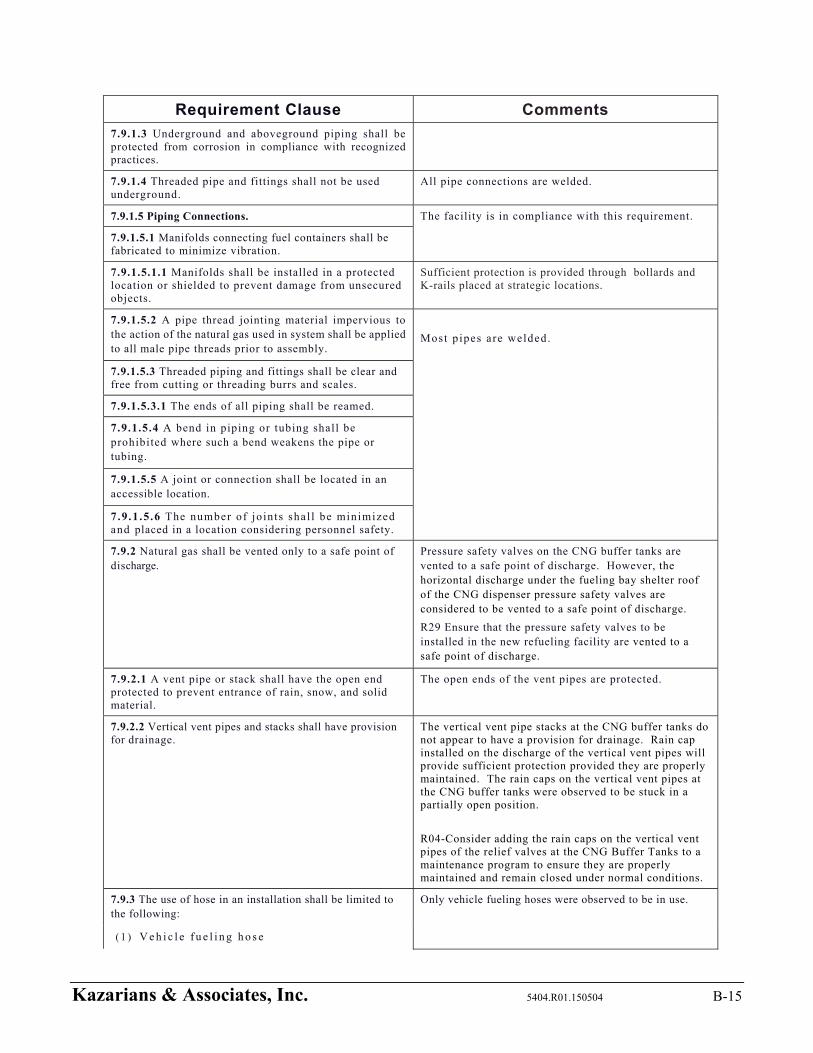
Kazarians & Associates, Inc. 5404.R01.150504 B-15
Requirement Clause Comments
7.9.1.3 Underground and aboveground piping shall be protected from corrosion in compliance with recognized practices.
7.9.1.4 Threaded pipe and fittings shall not be used underground.
All pipe connections are welded.
7.9.1.5 Piping Connections. The facility is in compliance with this requirement.
7.9.1.5.1 Manifolds connecting fuel containers shall be fabricated to minimize vibration.
7.9.1.5.1.1 Manifolds shall be installed in a protected location or shielded to prevent damage from unsecured objects.
Sufficient protection is provided through bollards and K-rails placed at strategic locations.
7.9.1.5.2 A pipe thread jointing material impervious to the action of the natural gas used in system shall be applied to all male pipe threads prior to assembly.
Most p ipes are welded.
7.9.1.5.3 Threaded piping and fittings shall be clear and free from cutting or threading burrs and scales.
7.9.1.5.3.1 The ends of all piping shall be reamed.
7.9.1.5.4 A bend in piping or tubing shall be prohibited where such a bend weakens the pipe or tubing.
7.9.1.5.5 A joint or connection shall be located in an accessible location.
7 .9 .1 .5.6 The number of jo in ts shal l be minimized and placed in a location considering personnel safety.
7.9.2 Natural gas shall be vented only to a safe point of discharge.
Pressure safety valves on the CNG buffer tanks are vented to a safe point of discharge. However, the horizontal discharge under the fueling bay shelter roof of the CNG dispenser pressure safety valves are considered to be vented to a safe point of discharge.
R29 Ensure that the pressure safety valves to be installed in the new refueling facility are vented to a safe point of discharge.
7.9.2.1 A vent pipe or stack shall have the open end protected to prevent entrance of rain, snow, and solid material.
The open ends of the vent pipes are protected.
7.9.2.2 Vertical vent pipes and stacks shall have provision for drainage.
The vertical vent pipe stacks at the CNG buffer tanks do not appear to have a provision for drainage. Rain cap installed on the discharge of the vertical vent pipes will provide sufficient protection provided they are properly maintained. The rain caps on the vertical vent pipes at the CNG buffer tanks were observed to be stuck in a partially open position.
R04-Consider adding the rain caps on the vertical vent pipes of the relief valves at the CNG Buffer Tanks to a maintenance program to ensure they are properly maintained and remain closed under normal conditions.
7.9.3 The use of hose in an installation shall be limited to the following:
Only vehicle fueling hoses were observed to be in use.
( 1 ) V e h i c l e f u e l i n g h o s e

Kazarians & Associates, Inc. 5404.R01.150504 B-16
Requirement Clause Comments
( 2 ) I n le t c onn ec t io n t o co mp res s io n eq u ip me n t
( 3 ) Section of metallic hose not exceeding 36 in. (910 mm) in length in a pipeline to provide flexibility where necessary
7.9.3.1 Each section shall be installed so that it is protected against mechanical damage and is visible for inspection.
The fueling hoses are in compliance with this requirement.
7.9.3.2 The manufacturer's identification shall be retained in each section.
7.9.4 At fueling stations, gas used for calibration and testing shall be vented to a safe location.
Recommendation R18
7.10 System Testing. All piping and hoses are pressurized on a consistent basis as part of normal operation.
7.10.1 Piping, tubing and hose, and hose assemblies shall be leak tested after assembly to prove them free from leaks at a pressure equal to at least the normal service pressure of that portion of the system.
7.10.2 Pressure relief valves shall be tested at least every 3 years.
Recommendation R18
7.11 Installation of Emergency Shutdown Equipment. This review is limited to the fueling facility and does not included natural gas components of the vehicles fueled at the facility. 7.11.1 Manually Operated Container Valve.
7.11.1.1 A manually operated container valve shall be pro-vided for each DOT or TC storage cylinder.
7.11.1.2 Individual groups of manifolded ASME storage vessels without individual storage vessel valves shall be limited to a maximum of 10,000 scf (283 m3).
Each CNG buffer tank is smaller than 283 m3, and each tank has a vessel valve.
7.11.1.2.1 Manifolds serving each group of ASME storage vessels shall be provided with a manually operated shutoff valve.
The CNG buffer tank manifolds each have a manually operated shutoff valve.
7.11.1.3 Individual ASME pressure vessels of any size, not part of a manifold system, shall have a manual shutoff valve.
The ASME CNG buffer tanks are part of a manifold system, and each CNG buffer tank has a manually operated shutoff valve.
7.11.1.4 A manually operated shutoff valve shall be installed at the outlet from the manifold.
The CNG buffer tank manifolds each have a manually operated shutoff valve at the outlet.
7.11.1.5 The valve in 7.11.1.3 shall be located downstream of the backflow check valve specified in 7.11.2.
The valve in 7.1.1.3 is not required, because the CNG buffer tanks are part of a manifold system.
7.11.2 The fill line on a storage container shall be equipped with a backflow check valve to prevent discharge of natural gas from the container in case of the rupture of the line, hose, fittings, or other equipment upstream of the storage containers.
The facility is in compliance with this requirement.
7.11.3 Where excess-flow check valves are used, the closing flow shall be greater than the maximum system design flow rate and less than the flow rating of the piping system that results from a complete line failure between the excess-flow valve and the equipment downstream of the excess-flow check valve.
Excess flow valves are not used.
7.11.4 Gas piping from an outdoor compressor or storage system into a building shall be provided with shutoff valves located outside the building.
Gas piping from an outdoor compressor or storage system does not enter into a building at the facility.
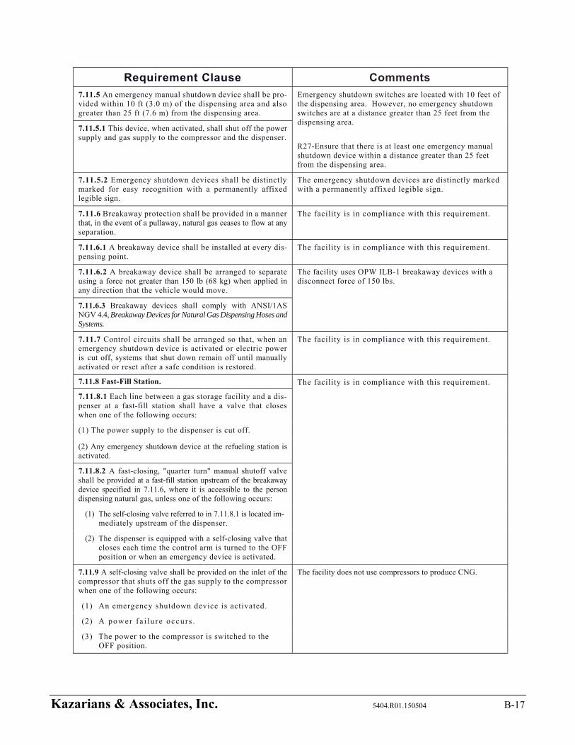
Kazarians & Associates, Inc. 5404.R01.150504 B-17
Requirement Clause Comments
7.11.5 An emergency manual shutdown device shall be pro-vided within 10 ft (3.0 m) of the dispensing area and also greater than 25 ft (7.6 m) from the dispensing area.
Emergency shutdown switches are located with 10 feet of the dispensing area. However, no emergency shutdown switches are at a distance greater than 25 feet from the dispensing area.
R27-Ensure that there is at least one emergency manual shutdown device within a distance greater than 25 feet from the dispensing area.
7.11.5.1 This device, when activated, shall shut off the power supply and gas supply to the compressor and the dispenser.
7.11.5.2 Emergency shutdown devices shall be distinctly marked for easy recognition with a permanently affixed legible sign.
The emergency shutdown devices are distinctly marked with a permanently affixed legible sign.
7.11.6 Breakaway protection shall be provided in a manner that, in the event of a pullaway, natural gas ceases to flow at any separation.
The facility is in compliance with this requirement.
7.11.6.1 A breakaway device shall be installed at every dis-pensing point.
The facility is in compliance with this requirement.
7.11.6.2 A breakaway device shall be arranged to separate using a force not greater than 150 lb (68 kg) when applied in any direction that the vehicle would move.
The facility uses OPW ILB-1 breakaway devices with a disconnect force of 150 lbs.
7.11.6.3 Breakaway devices shall comply with ANSI/1AS NGV 4.4, Breakaway Devices for Natural Gas Dispensing Hoses and Systems.
7.11.7 Control circuits shall be arranged so that, when an emergency shutdown device is activated or electric power is cut off, systems that shut down remain off until manually activated or reset after a safe condition is restored.
The facility is in compliance with this requirement.
7.11.8 Fast-Fill Station. The facility is in compliance with this requirement.
7.11.8.1 Each line between a gas storage facility and a dis-penser at a fast-fill station shall have a valve that closes when one of the following occurs:
(1) The power supply to the dispenser is cut off.
(2) Any emergency shutdown device at the refueling station is activated.
7.11.8.2 A fast-closing, "quarter turn" manual shutoff valve shall be provided at a fast-fill station upstream of the breakaway device specified in 7.11.6, where it is accessible to the person dispensing natural gas, unless one of the following occurs:
(1) The self-closing valve referred to in 7.11.8.1 is located im-mediately upstream of the dispenser.
(2) The dispenser is equipped with a self-closing valve that closes each time the control arm is turned to the OFF position or when an emergency device is activated.
7.11.9 A self-closing valve shall be provided on the inlet of the compressor that shuts off the gas supply to the compressor when one of the following occurs:
The facility does not use compressors to produce CNG.
(1) An emergency shutdown device is activated.
(2) A power f a i lu re occurs .
(3) The power to the compressor is switched to the OFF position.
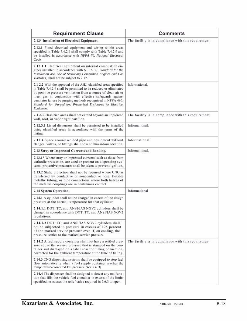
Kazarians & Associates, Inc. 5404.R01.150504 B-18
Requirement Clause Comments 7.12* Installation of Electrical Equipment. The facility is in compliance with this requirement.
7.12.1 Fixed electrical equipment and wiring within areas specified in Table 7.4.2.9 shall comply with Table 7.4.2.9 and be installed in accordance with NFPA 70, National Electrical Code.
7.12.1.1 Electrical equipment on internal combustion en-gines installed in accordance with NFPA 37, Standard for the Installation and Use of Stationary Combustion Engines and Gas Turbines, shall not be subject to 7.12.1.
7.1 2.2 With the approval of the AHJ, classified areas specified in Table 7.4.2.9 shall be permitted to be reduced or eliminated by positive pressure ventilation from a source of clean air or inert gas in conjunction with effective safeguards against ventilator failure by purging methods recognized in NFPA 496, Standard for Purged and Pressurized Enclosures for Electrical Equipment.
Informational.
7.1 2.3 Classified areas shall not extend beyond an unpierced wall, roof, or vapor tight partition.
The facility is in compliance with this requirement.
7.12.3.1 Listed dispensers shall be permitted to be installed using classified areas in accordance with the terms of the listing.
Informational.
7.12.4 Space around welded pipe and equipment without flanges, valves, or fittings shall be a nonhazardous location.
Informational.
7.13 Stray or Impressed Currents and Bonding. Informational.
7.13.1* Where stray or impressed currents, such as those from cathodic protection, are used or present on dispensing sys-tems, protective measures shall be taken to prevent ignition.
7.13.2 Static protection shall not be required where CNG is transferred by conductive or nonconductive hose, flexible metallic tubing, or pipe connections where both halves of the metallic couplings are in continuous contact.
7.14 System Operation. Informational
7.14.1 A cylinder shall not be charged in excess of the design pressure at the normal temperature for that cylinder.
7.14.1.1 DOT, TC, and ANSI/IAS NGV2 cylinders shall be charged in accordance with DOT, TC, and ANSI/IAS NGV2 regulations.
7.14.1.2 DOT, TC, and ANSI/IAS NGV2 cylinders shall not be subjected to pressure in excess of 125 percent of the marked service pressure even if, on cooling, the pressure settles to the marked service pressure.
7.14.2 A fuel supply container shall not have a settled pres-sure above the service pressure that is stamped on the con-tainer and displayed on a label near the filling connection, corrected for the ambient temperature at the time of filling.
The facility is in compliance with this requirement.
7.14.3 CNG dispensing systems shall be equipped to stop fuel flow automatically when a fuel supply container reaches the temperature-corrected fill pressure (see 7.6.3).
7.14.4 The dispenser shall be designed to detect any malfunc-tion that fills the vehicle fuel container in excess of the limits specified, or causes the relief valve required in 7.6.3 to open.
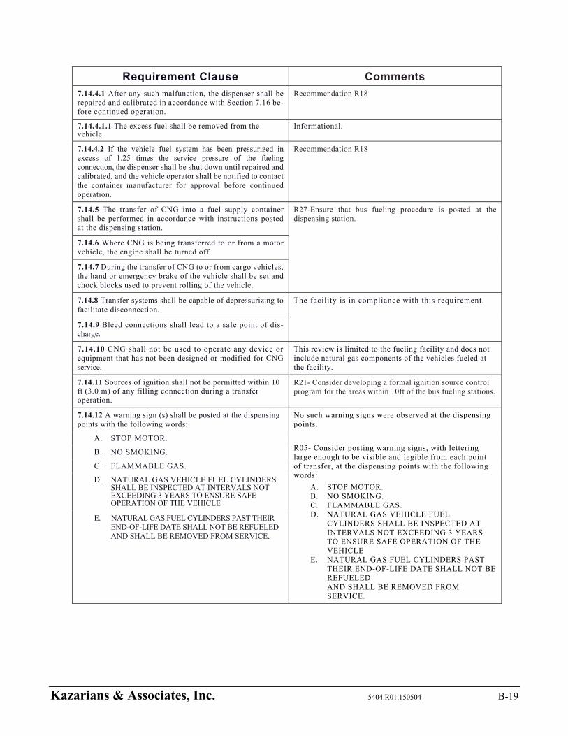
Kazarians & Associates, Inc. 5404.R01.150504 B-19
Requirement Clause Comments
7.14.4.1 After any such malfunction, the dispenser shall be repaired and calibrated in accordance with Section 7.16 be-fore continued operation.
Recommendation R18
7.14.4.1.1 The excess fuel shall be removed from the vehicle.
Informational.
7.14.4.2 If the vehicle fuel system has been pressurized in excess of 1.25 times the service pressure of the fueling connection, the dispenser shall be shut down until repaired and calibrated, and the vehicle operator shall be notified to contact the container manufacturer for approval before continued operation.
Recommendation R18
7.14.5 The transfer of CNG into a fuel supply container shall be performed in accordance with instructions posted at the dispensing station.
R27-Ensure that bus fueling procedure is posted at the dispensing station.
7.14.6 Where CNG is being transferred to or from a motor vehicle, the engine shall be turned off.
7.14.7 During the transfer of CNG to or from cargo vehicles, the hand or emergency brake of the vehicle shall be set and chock blocks used to prevent rolling of the vehicle.
7.14.8 Transfer systems shall be capable of depressurizing to facilitate disconnection.
The facility is in compliance with this requirement.
7.14.9 Bleed connections shall lead to a safe point of dis-charge.
7.14.10 CNG shall not be used to operate any device or equipment that has not been designed or modified for CNG service.
This review is limited to the fueling facility and does not include natural gas components of the vehicles fueled at the facility.
7.14.11 Sources of ignition shall not be permitted within 10 ft (3.0 m) of any filling connection during a transfer operation.
R21- Consider developing a formal ignition source control program for the areas within 10ft of the bus fueling stations.
7.14.12 A warning sign (s) shall be posted at the dispensing points with the following words:
No such warning signs were observed at the dispensing points.
R05- Consider posting warning signs, with lettering large enough to be visible and legible from each point of transfer, at the dispensing points with the following words:
A. STOP MOTOR. B. NO SMOKING. C. FLAMMABLE GAS. D. NATURAL GAS VEHICLE FUEL
CYLINDERS SHALL BE INSPECTED AT INTERVALS NOT EXCEEDING 3 YEARS TO ENSURE SAFE OPERATION OF THE VEHICLE
E. NATURAL GAS FUEL CYLINDERS PAST THEIR END-OF-LIFE DATE SHALL NOT BE REFUELED AND SHALL BE REMOVED FROM SERVICE.
A. STOP MOTOR.
B. NO SMOKING.
C. FLAMMABLE GAS.
D. NATURAL GAS VEHICLE FUEL CYLINDERS SHALL BE INSPECTED AT INTERVALS NOT EXCEEDING 3 YEARS TO ENSURE SAFE OPERATION OF THE VEHICLE
E. NATURAL GAS FUEL CYLINDERS PAST THEIR END-OF-LIFE DATE SHALL NOT BE REFUELED AND SHALL BE REMOVED FROM SERVICE.
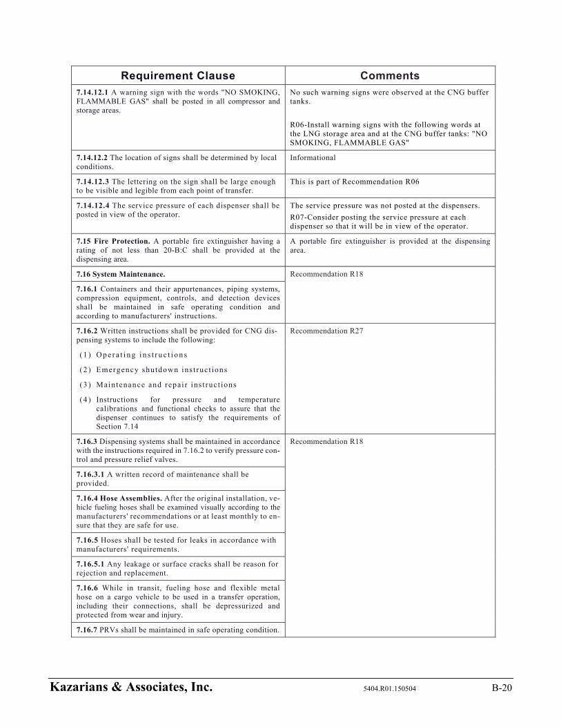
Kazarians & Associates, Inc. 5404.R01.150504 B-20
Requirement Clause Comments
7.14.12.1 A warning sign with the words "NO SMOKING, FLAMMABLE GAS" shall be posted in all compressor and storage areas.
No such warning signs were observed at the CNG buffer tanks.
R06-Install warning signs with the following words at the LNG storage area and at the CNG buffer tanks: "NO SMOKING, FLAMMABLE GAS"
7.14.12.2 The location of signs shall be determined by local conditions.
Informational
7.14.12.3 The lettering on the sign shall be large enough to be visible and legible from each point of transfer.
This is part of Recommendation R06
7.14.12.4 The service pressure of each dispenser shall be posted in view of the operator.
The service pressure was not posted at the dispensers.
R07-Consider posting the service pressure at each dispenser so that it will be in view of the operator.
7.15 Fire Protection. A portable fire extinguisher having a rating of not less than 20-B:C shall be provided at the dispensing area.
A portable fire extinguisher is provided at the dispensing area.
7.16 System Maintenance. Recommendation R18
7.16.1 Containers and their appurtenances, piping systems, compression equipment, controls, and detection devices shall be maintained in safe operating condition and according to manufacturers' instructions.
7.16.2 Written instructions shall be provided for CNG dis-pensing systems to include the following:
Recommendation R27
( 1 ) O p e r a t i n g i n s t r u c t i o n s
( 2 ) Emergency shutdown ins t ruct ions
( 3 ) Maintenance and repai r inst ruct ions
( 4 ) Instructions for pressure and temperature calibrations and functional checks to assure that the dispenser continues to satisfy the requirements of Section 7.14
7.16.3 Dispensing systems shall be maintained in accordance with the instructions required in 7.16.2 to verify pressure con-trol and pressure relief valves.
Recommendation R18
7.16.3.1 A written record of maintenance shall be provided.
7.16.4 Hose Assemblies. After the original installation, ve-hicle fueling hoses shall be examined visually according to the manufacturers' recommendations or at least monthly to en-sure that they are safe for use.
7.16.5 Hoses shall be tested for leaks in accordance with manufacturers' requirements.
7.16.5.1 Any leakage or surface cracks shall be reason for rejection and replacement.
7.16.6 While in transit, fueling hose and flexible metal hose on a cargo vehicle to be used in a transfer operation, including their connections, shall be depressurized and protected from wear and injury.
7.16.7 PRVs shall be maintained in safe operating condition.

Kazarians & Associates, Inc. 5404.R01.150504 B-21
Requirement Clause Comments
7.16.8 Maintenance personnel shall be trained in leak detec-tion procedures and equipment in accordance with manufac-turers' recommendations.
R20-Develop a formal procedure to address leaks in the LNG storage and handling systems.
7.17 Vehicle Fueling Appliances in Nonresidential Occupancies.
The facility does not utilize VFAs (VFA – a listed, self-contained system that compresses natural gas and dispenses the natural gas to a vehicle’s engine fueling system. 7.17.1 VFAs shall not exceed a gas flow of 10
scf/min (0.28 SCM/min).
7.17.2 VFAs shall be listed.
7.17.3 The installation of VFAs shall be exempt from the re-quirements of Sections 5.5 through 5.10, 7.2 through 7.4, 7.6, and 7.8 through 7.16.
7.17.4 VFAs shall be permitted to be used to fill stationary containers at vehicle fueling locations.
7.17.4.1 The method of connecting the WA to such storage shall comply with the provisions of Chapters 5 and 7 and shall be approved.
7.17.4.2 The provisions of 7.17.3 shall apply to the VFA where connected to stationary containers at vehicle fueling loca-tions.
7.17.5 The installation of VFAs shall comply with the require-ments of Chapter 8.
7.17.5.1 The requirements of 8.1.2 and 8.1.3 shall not apply to the installation of VFAs.
7.17.5.2 Gas detectors shall be located in accordance with good engineering practice.
7.17.6 VFAs shall not be installed within 10 ft (3.0 m) of any flammable gas or liquid storage.
7.17.6.1 Storage in the vehicle fuel supply container shall not be subject to 7.17.6.
7.17.7 Where installed indoors in public assembly and educa-tional occupancies, a VFA shall be located in a portion of the occupancy where NFPA 101, Life Safety Code, or the local building code permits the installation of hazardous equipment.
7.17.7.1 Where the VFA is located outdoors, the dispensing point shall be permitted to be located indoors without the need for a separate room.
Chapter 10 LNG Fueling Facilities
10.1 Application. Informational
10.1.1 This chapter applies to the design, siting, construc-tion, installation, spill containment, and operation of containers, pressure vessels, pumps, vaporization equipment, buildings, structures, and associated equipment used for the storage and dispensing of LNG and L/CNG as engine fuel for vehicles of all types.
10.1.2 All dispensing of LNG, including mobile refueling, into vehicle onboard fuel systems shall comply with the re-quirements of a permanent LNG refueling installation at the point of dispensing fuel.
The facility does not dispense LNG.

Kazarians & Associates, Inc. 5404.R01.150504 B-22
Requirement Clause Comments
10.2 Facility Design. The facility is not accessible to the public.
10.2.1 General.
10.2.1.1 LNG fueling facilities that are permitted to be un-attended shall be designed to secure all equipment from tampering.
10.2.1.2 Storage and transfer equipment at unattended facilities shall be secured to prevent tampering.
10.2.1.3 Operating instructions identifying the location and operation of emergency controls shall be posted conspicu-ously in the facility area.
Emergency shutdown buttons are clearly labeled. Electrical shutdown located under the CNG dispensing covered area. CNG dispenser shut down located on the side of the dispenser.
10.2.1.4 LNG fueling facilities transferring LNG during the night shall have permanent, adequate lighting at points of transfer and operation.
The LNG transfer location has adequate lighting at the point of transfer and operation.
10.2.1.5 Designers, fabricators, and constructors of LNG fu-eling facilities shall be competent in the design, fabrication, and construction of LNG containers, cryogenic equipment, loading and unloading systems, fire protection equipment, methane detection, and other components of the facility.
The original design and current additions have been done by companies experienced in CLNG systems.
10.2.1.6 Supervision shall be provided for the fabrication, construction, and acceptance tests of facility components to the extent necessary to ensure that facilities are structurally sound, suitable for the service, and otherwise in compliance with this code.
10.2.1.7 LNG refueling sites utilizing or dispensing saturated LNG with personnel in the immediate vicinity shall provide barrier walls or equal protection in order to protect the refu-eling operator and vehicle.
The facility is not a LNG refueling site.
10.2.1.8 All facility piping other than the refueling hose to the vehicle shall be behind a barrier, which in the case of an equipment or device malfunction deflects the saturated LNG upward.
LNG piping between the LNG storage building and the LNG vaporizers is not behind a barrier.
R08-Consider installing a barrier at the LNG piping between the LNG storage building and the LNG vaporizers so that in the case of an integrity failure of the LNG containing piping saturated LNG is deflected upward.
10.2.2 Siting. The facility is in compliance with this requirement
10.2.2.1 LNG tanks and their associated equipment shall not be located where exposed to failure of overhead electric power lines operating over 600 volts.
10.2.2.2 Vaulted or underground installations shall be deemed to provide engineered protection from overhead power lines.
Informational
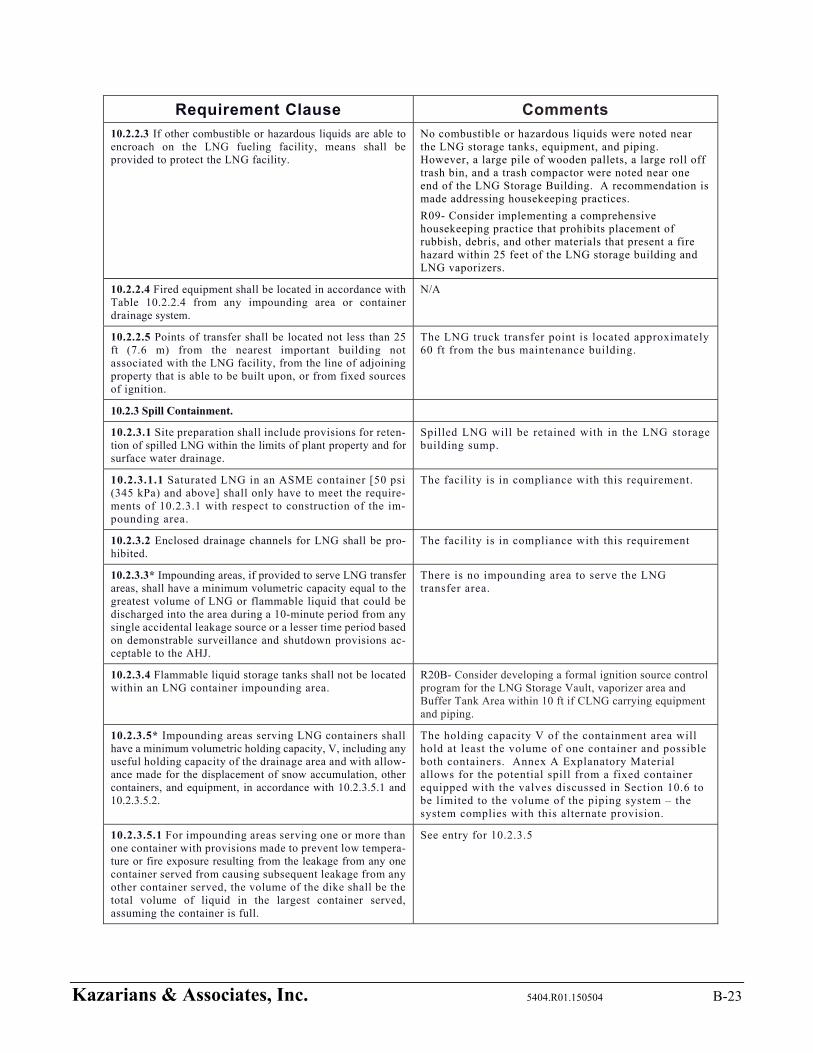
Kazarians & Associates, Inc. 5404.R01.150504 B-23
Requirement Clause Comments
10.2.2.3 If other combustible or hazardous liquids are able to encroach on the LNG fueling facility, means shall be provided to protect the LNG facility.
No combustible or hazardous liquids were noted near the LNG storage tanks, equipment, and piping. However, a large pile of wooden pallets, a large roll off trash bin, and a trash compactor were noted near one end of the LNG Storage Building. A recommendation is made addressing housekeeping practices.
R09- Consider implementing a comprehensive housekeeping practice that prohibits placement of rubbish, debris, and other materials that present a fire hazard within 25 feet of the LNG storage building and LNG vaporizers.
10.2.2.4 Fired equipment shall be located in accordance with Table 10.2.2.4 from any impounding area or container drainage system.
N/A
10.2.2.5 Points of transfer shall be located not less than 25 ft (7.6 m) from the nearest important building not associated with the LNG facility, from the line of adjoining property that is able to be built upon, or from fixed sources of ignition.
The LNG truck transfer point is located approximately 60 ft from the bus maintenance building.
10.2.3 Spill Containment.
10.2.3.1 Site preparation shall include provisions for reten-tion of spilled LNG within the limits of plant property and for surface water drainage.
Spilled LNG will be retained with in the LNG storage building sump.
10.2.3.1.1 Saturated LNG in an ASME container [50 psi (345 kPa) and above] shall only have to meet the require-ments of 10.2.3.1 with respect to construction of the im-pounding area.
The facility is in compliance with this requirement.
10.2.3.2 Enclosed drainage channels for LNG shall be pro-hibited.
The facility is in compliance with this requirement
10.2.3.3* Impounding areas, if provided to serve LNG transfer areas, shall have a minimum volumetric capacity equal to the greatest volume of LNG or flammable liquid that could be discharged into the area during a 10-minute period from any single accidental leakage source or a lesser time period based on demonstrable surveillance and shutdown provisions ac-ceptable to the AHJ.
There is no impounding area to serve the LNG transfer area.
10.2.3.4 Flammable liquid storage tanks shall not be located within an LNG container impounding area.
R20B- Consider developing a formal ignition source control program for the LNG Storage Vault, vaporizer area and Buffer Tank Area within 10 ft if CLNG carrying equipment and piping.
10.2.3.5* Impounding areas serving LNG containers shall have a minimum volumetric holding capacity, V, including any useful holding capacity of the drainage area and with allow-ance made for the displacement of snow accumulation, other containers, and equipment, in accordance with 10.2.3.5.1 and 10.2.3.5.2.
The holding capacity V of the containment area will hold at least the volume of one container and possible both containers. Annex A Explanatory Material allows for the potential spill from a fixed container equipped with the valves discussed in Section 10.6 to be limited to the volume of the piping system – the system complies with this alternate provision.
10.2.3.5.1 For impounding areas serving one or more than one container with provisions made to prevent low tempera-ture or fire exposure resulting from the leakage from any one container served from causing subsequent leakage from any other container served, the volume of the dike shall be the total volume of liquid in the largest container served, assuming the container is full.
See entry for 10.2.3.5
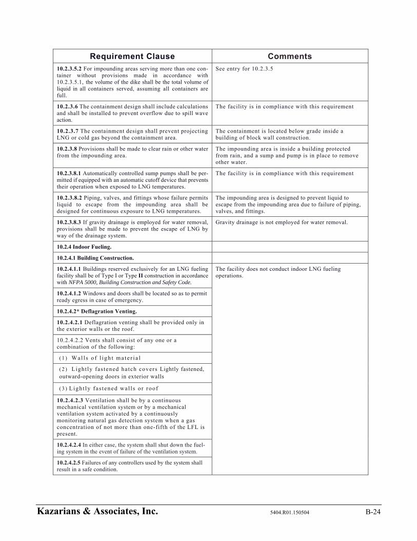
Kazarians & Associates, Inc. 5404.R01.150504 B-24
Requirement Clause Comments
10.2.3.5.2 For impounding areas serving more than one con-tainer without provisions made in accordance with 10.2.3.5.1, the volume of the dike shall be the total volume of liquid in all containers served, assuming all containers are full.
See entry for 10.2.3.5
10.2.3.6 The containment design shall include calculations and shall be installed to prevent overflow due to spill wave action.
The facility is in compliance with this requirement
10.2.3.7 The containment design shall prevent projecting LNG or cold gas beyond the containment area.
The containment is located below grade inside a building of block wall construction.
10.2.3.8 Provisions shall be made to clear rain or other water from the impounding area.
The impounding area is inside a building protected from rain, and a sump and pump is in place to remove other water.
10.2.3.8.1 Automatically controlled sump pumps shall be per-mitted if equipped with an automatic cutoff device that prevents their operation when exposed to LNG temperatures.
The facility is in compliance with this requirement
10.2.3.8.2 Piping, valves, and fittings whose failure permits liquid to escape from the impounding area shall be designed for continuous exposure to LNG temperatures.
The impounding area is designed to prevent liquid to escape from the impounding area due to failure of piping, valves, and fittings.
10.2.3.8.3 If gravity drainage is employed for water removal, provisions shall be made to prevent the escape of LNG by way of the drainage system.
Gravity drainage is not employed for water removal.
10.2.4 Indoor Fueling.
10.2.4.1 Building Construction.
10.2.4.1.1 Buildings reserved exclusively for an LNG fueling facility shall be of Type I or Type II construction in accordance with NFPA 5000, Building Construction and Safety Code.
The facility does not conduct indoor LNG fueling operations.
10.2.4.1.2 Windows and doors shall be located so as to permit ready egress in case of emergency.
10.2.4.2* Deflagration Venting.
10.2.4.2.1 Deflagration venting shall be provided only in the exterior walls or the roof.
10.2.4.2.2 Vents shall consist of any one or a combination of the following:
( 1 ) Wal l s o f l i gh t ma t e r i a l
( 2 ) Light ly fas tened hatch covers Lightly fastened, outward-opening doors in exterior walls
( 3 ) Ligh t ly fa s t ened wa l l s o r roof
10.2.4.2.3 Ventilation shall be by a continuous mechanical ventilation system or by a mechanical ventilation system activated by a continuously monitoring natural gas detection system when a gas concentration of not more than one-fifth of the LFL is present.
10.2.4.2.4 In either case, the system shall shut down the fuel-ing system in the event of failure of the ventilation system.
10.2.4.2.5 Failures of any controllers used by the system shall result in a safe condition.
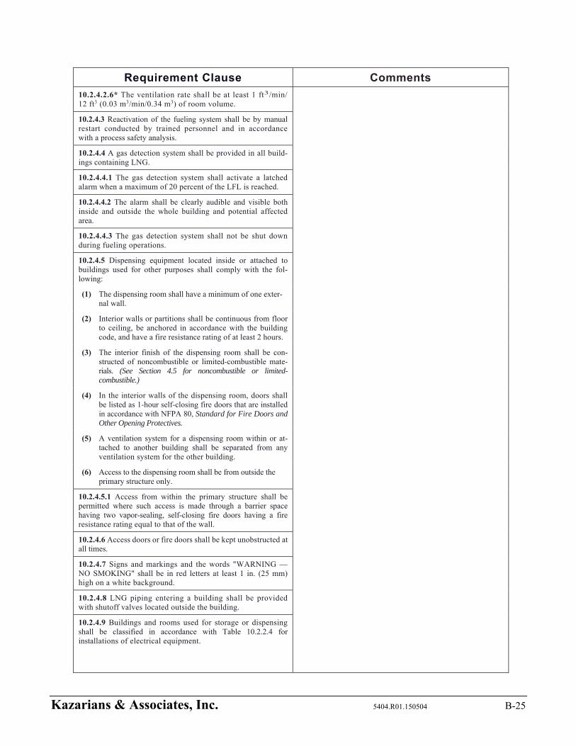
Kazarians & Associates, Inc. 5404.R01.150504 B-25
Requirement Clause Comments
10.2.4.2.6* The ventilation rate shall be at least 1 ft3/min/ 12 ft3 (0.03 m3/min/0.34 m3) of room volume.
10.2.4.3 Reactivation of the fueling system shall be by manual restart conducted by trained personnel and in accordance with a process safety analysis.
10.2.4.4 A gas detection system shall be provided in all build-ings containing LNG.
10.2.4.4.1 The gas detection system shall activate a latched alarm when a maximum of 20 percent of the LFL is reached.
10.2.4.4.2 The alarm shall be clearly audible and visible both inside and outside the whole building and potential affected area.
10.2.4.4.3 The gas detection system shall not be shut down during fueling operations.
10.2.4.5 Dispensing equipment located inside or attached to buildings used for other purposes shall comply with the fol-lowing:
(1) The dispensing room shall have a minimum of one exter-nal wall.
(2) Interior walls or partitions shall be continuous from floor to ceiling, be anchored in accordance with the building code, and have a fire resistance rating of at least 2 hours.
(3) The interior finish of the dispensing room shall be con-structed of noncombustible or limited-combustible mate-rials. (See Section 4.5 for noncombustible or limited-combustible.)
(4) In the interior walls of the dispensing room, doors shall be listed as 1-hour self-closing fire doors that are installed in accordance with NFPA 80, Standard for Fire Doors and Other Opening Protectives.
(5) A ventilation system for a dispensing room within or at-tached to another building shall be separated from any ventilation system for the other building.
(6) Access to the dispensing room shall be from outside the primary structure only.
10.2.4.5.1 Access from within the primary structure shall be permitted where such access is made through a barrier space having two vapor-sealing, self-closing fire doors having a fire resistance rating equal to that of the wall.
10.2.4.6 Access doors or fire doors shall be kept unobstructed at all times.
10.2.4.7 Signs and markings and the words "WARNING —NO SMOKING" shall be in red letters at least 1 in. (25 mm) high on a white background.
10.2.4.8 LNG piping entering a building shall be provided with shutoff valves located outside the building.
10.2.4.9 Buildings and rooms used for storage or dispensing shall be classified in accordance with Table 10.2.2.4 for installations of electrical equipment.
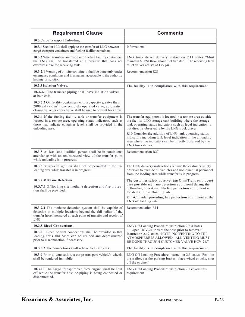
Kazarians & Associates, Inc. 5404.R01.150504 B-26
Requirement Clause Comments
10.3 Cargo Transport Unloading.
10.3.1 Section 10.3 shall apply to the transfer of LNG between cargo transport containers and fueling facility containers.
Informational
10.3.2 When transfers are made into fueling facility containers, the LNG shall be transferred at a pressure that does not overpressurize the receiving tank.
LNG truck driver delivery instruction 2.11 states “Must maintain 60 PSI throughout fuel transfer.” The receiving tank relief valves are set at 175 psi.
10.3.2.1 Venting of on-site containers shall be done only under emergency conditions and in a manner acceptable to the authority having jurisdiction.
Recommendation R23
10.3.3 Isolation Valves. The facility is in compliance with this requirement
10.3.3.1 The transfer piping shall have isolation valves at both ends.
10.3.3.2 On facility containers with a capacity greater than 2000 gal (7.6 m3), one remotely operated valve, automatic closing valve, or check valve shall be used to prevent backflow.
10.3.4 If the fueling facility tank or transfer equipment is located in a remote area, operating status indicators, such as those that indicate container level, shall be provided in the unloading area.
The transfer equipment is located in a remote area outside the facility LNG storage tank building where the storage tank operating status indicators such as level indication is not directly observable by the LNG truck driver.
R10-Consider the addition of LNG tank operating status indicators including tank level indication in the unloading area where the indicators can be directly observed by the LNG truck driver.
10.3.5 At least one qualified person shall be in continuous attendance with an unobstructed view of the transfer point while unloading is in progress.
Recommendation R27
10.3.6 Sources of ignition shall not be permitted in the un-loading area while transfer is in progress.
The LNG delivery instructions require the customer safety observer to exclude all vehicles and non-essential personnel from the loading area while transfer is in progress.
10.3.7 Methane Detection. The customer safety observer (an OmniTrans employee) uses portable methane detection equipment during the offloading operation. No fire protection equipment is located at the offloading site.
R11-Consider providing fire protection equipment at the LNG offloading site.
10.3.7.1 Offloading site methane detection and fire protec-tion shall be provided.
10.3.7.2 The methane detection system shall be capable of detection at multiple locations beyond the full radius of the transfer hose, measured at each point of transfer and receipt of LNG.
Recommendation R11
10.3.8 Bleed Connections. LNG Off-Loading Procedure instruction 2.2.4 states “…Open HCV-21 to vent the hose prior to removal.” Instruction 2.12 states “NOTE: NO VENTING TO THE ATMOSPHERE IS ALLOWED. ALL VENTING MUST BE DONE THROUGH CUSTOMER VALVE HCV-21.”
10.3.8.1 Bleed or vent connections shall be provided so that loading arms and hoses can be drained and depressurized prior to disconnection if necessary.
10.3.8.2 The connections shall relieve to a safe area. The facility is in compliance with this requirement
10.3.9 Prior to connection, a cargo transport vehicle's wheels shall be rendered immobile.
LNG Off-Loading Procedure instruction 2.5 states “Position the trailer, set the parking brakes, place wheel chocks, shut off the engine.”
10.3.10 The cargo transport vehicle's engine shall be shut off while the transfer hose or piping is being connected or disconnected.
LNG Off-Loading Procedure instruction 2.5 covers this requirement.
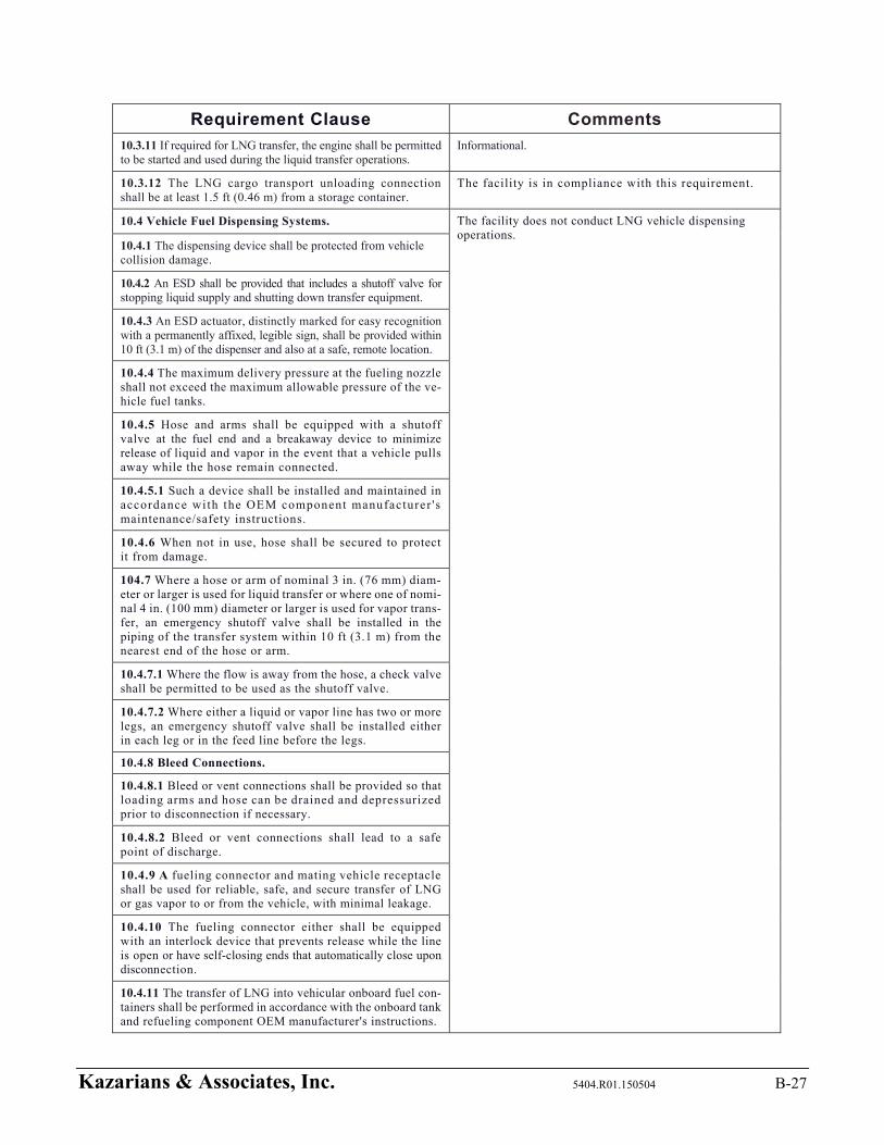
Kazarians & Associates, Inc. 5404.R01.150504 B-27
Requirement Clause Comments
10.3.11 If required for LNG transfer, the engine shall be permitted to be started and used during the liquid transfer operations.
Informational.
10.3.12 The LNG cargo transport unloading connection shall be at least 1.5 ft (0.46 m) from a storage container.
The facility is in compliance with this requirement.
10.4 Vehicle Fuel Dispensing Systems. The facility does not conduct LNG vehicle dispensing operations.
10.4.1 The dispensing device shall be protected from vehicle collision damage.
10.4.2 An ESD shall be provided that includes a shutoff valve for stopping liquid supply and shutting down transfer equipment.
10.4.3 An ESD actuator, distinctly marked for easy recognition with a permanently affixed, legible sign, shall be provided within 10 ft (3.1 m) of the dispenser and also at a safe, remote location.
10.4.4 The maximum delivery pressure at the fueling nozzle shall not exceed the maximum allowable pressure of the ve-hicle fuel tanks.
10.4.5 Hose and arms shall be equipped with a shutoff valve at the fuel end and a breakaway device to minimize release of liquid and vapor in the event that a vehicle pulls away while the hose remain connected.
10.4.5.1 Such a device shall be installed and maintained in accordance with the OEM component manufacturer 's maintenance/safety instructions.
10.4.6 When not in use, hose shall be secured to protect it from damage.
104.7 Where a hose or arm of nominal 3 in. (76 mm) diam-eter or larger is used for liquid transfer or where one of nomi-nal 4 in. (100 mm) diameter or larger is used for vapor trans-fer, an emergency shutoff valve shall be installed in the piping of the transfer system within 10 ft (3.1 m) from the nearest end of the hose or arm.
10.4.7.1 Where the flow is away from the hose, a check valve shall be permitted to be used as the shutoff valve.
10.4.7.2 Where either a liquid or vapor line has two or more legs, an emergency shutoff valve shall be installed either in each leg or in the feed line before the legs.
10.4.8 Bleed Connections.
10.4.8.1 Bleed or vent connections shall be provided so that loading arms and hose can be drained and depressurized prior to disconnection if necessary.
10.4.8.2 Bleed or vent connections shall lead to a safe point of discharge.
10.4.9 A fueling connector and mating vehicle receptacle shall be used for reliable, safe, and secure transfer of LNG or gas vapor to or from the vehicle, with minimal leakage.
10.4.10 The fueling connector either shall be equipped with an interlock device that prevents release while the line is open or have self-closing ends that automatically close upon disconnection.
10.4.11 The transfer of LNG into vehicular onboard fuel con-tainers shall be performed in accordance with the onboard tank and refueling component OEM manufacturer's instructions.
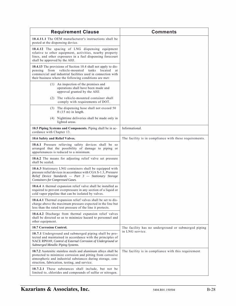
Kazarians & Associates, Inc. 5404.R01.150504 B-28
Requirement Clause Comments
10.4.11.1 The OEM manufacturer's instructions shall be posted at the dispensing device.
10.4.12 The spacing of LNG dispensing equipment relative to other equipment, activities, nearby property lines, and other exposures in a fuel dispensing forecourt shall be approved by the AHJ.
10.4.13 The provisions of Section 10.4 shall not apply to dis-pensing from vehicle-mounted tanks located at commercial and industrial facilities used in connection with their business where the following conditions are met:
(1) An inspection of the premises and operations shall have been made and approval granted by the AHJ.
(2) The vehicle-mounted container shall comply with requirements of DOT.
(3) The dispensing hose shall not exceed 50 ft (15 m) in length.
(4) Nighttime deliveries shall be made only in lighted areas.
10.5 Piping Systems and Components. Piping shall be in ac-cordance with Chapter 13.
Informational.
10.6 Safety and Relief Valves. The facility is in compliance with these requirements.
10.6.1 Pressure relieving safety devices shall be so arranged that the possibility of damage to piping or appurtenances is reduced to a minimum.
10.6.2 The means for adjusting relief valve set pressure shall be sealed.
10.6.3 Stationary LNG containers shall be equipped with pressure relief devices in accordance with CGA S-1.3, Pressure Relief Device Standards — Part 3 — Stationary Storage Containers for Compressed Gases.
10.6.4 A thermal expansion relief valve shall be installed as required to prevent overpressure in any section of a liquid or cold vapor pipeline that can be isolated by valves.
10.6.4.1 Thermal expansion relief valves shall be set to dis-charge above the maximum pressure expected in the line but less than the rated test pressure of the line it protects.
10.6.4.2 Discharge from thermal expansion relief valves shall be directed so as to minimize hazard to personnel and other equipment.
10.7 Corrosion Control. The facility has no underground or submerged piping in LNG service.
10.7.1 Underground and submerged piping shall be pro-tected and maintained in accordance with the principles of NACE RP0169, Control of External Corrosion of Underground or Submerged Metallic Piping Systems.
10.7.2 Austenitic stainless steels and aluminum alloys shall be protected to minimize corrosion and pitting from corrosive atmospheric and industrial substances during storage, con-struction, fabrication, testing, and service.
The facility is in compliance with this requirement
10.7.2.1 These substances shall include, but not be limited to, chlorides and compounds of sulfur or nitrogen.
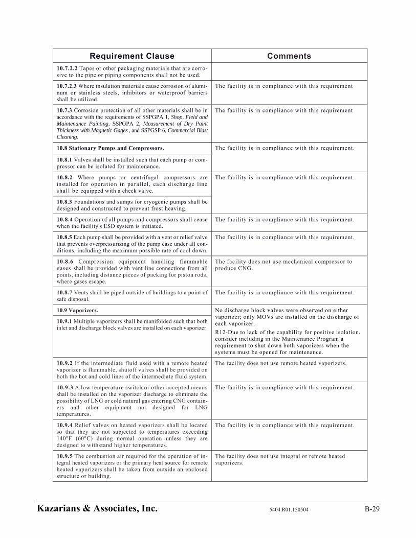
Kazarians & Associates, Inc. 5404.R01.150504 B-29
Requirement Clause Comments
10.7.2.2 Tapes or other packaging materials that are corro-sive to the pipe or piping components shall not be used.
10.7.2.3 Where insulation materials cause corrosion of alumi-num or stainless steels, inhibitors or waterproof barriers shall be utilized.
The facility is in compliance with this requirement
10.7.3 Corrosion protection of all other materials shall be in accordance with the requirements of SSPGPA 1, Shop, Field and Maintenance Painting, SSPGPA 2, Measurement of Dry Paint Thickness with Magnetic Gages-, and SSPGSP 6, Commercial Blast Cleaning.
The facility is in compliance with this requirement
10.8 Stationary Pumps and Compressors. The facility is in compliance with this requirement.
10.8.1 Valves shall be installed such that each pump or com-pressor can be isolated for maintenance.
10.8.2 Where pumps or centrifugal compressors are installed for operation in parallel, each discharge l ine shall be equipped with a check valve.
The facility is in compliance with this requirement.
10.8.3 Foundations and sumps for cryogenic pumps shall be designed and constructed to prevent frost heaving.
10.8.4 Operation of all pumps and compressors shall cease when the facility's ESD system is initiated.
The facility is in compliance with this requirement.
10.8.5 Each pump shall be provided with a vent or relief valve that prevents overpressurizing of the pump case under all con-ditions, including the maximum possible rate of cool down.
The facility is in compliance with this requirement.
10.8.6 Compression equipment handling flammable gases shall be provided with vent line connections from all points, including distance pieces of packing for piston rods, where gases escape.
The facility does not use mechanical compressor to produce CNG.
10.8.7 Vents shall be piped outside of buildings to a point of safe disposal.
The facility is in compliance with this requirement.
10.9 Vaporizers. No discharge block valves were observed on either vaporizer; only MOVs are installed on the discharge of each vaporizer.
R12-Due to lack of the capability for positive isolation, consider including in the Maintenance Program a requirement to shut down both vaporizers when the systems must be opened for maintenance.
10.9.1 Multiple vaporizers shall be manifolded such that both inlet and discharge block valves are installed on each vaporizer.
10.9.2 If the intermediate fluid used with a remote heated vaporizer is flammable, shutoff valves shall be provided on both the hot and cold lines of the intermediate fluid system.
The facility does not use remote heated vaporizers.
10.9.3 A low temperature switch or other accepted means shall be installed on the vaporizer discharge to eliminate the possibility of LNG or cold natural gas entering CNG contain-ers and other equipment not designed for LNG temperatures.
The facility is in compliance with this requirement.
10.9.4 Relief valves on heated vaporizers shall be located so that they are not subjected to temperatures exceeding 140°F (60°C) during normal operation unless they are designed to withstand higher temperatures.
The facility is in compliance with this requirement.
10.9.5 The combustion air required for the operation of in-tegral heated vaporizers or the primary heat source for remote heated vaporizers shall be taken from outside an enclosed structure or building.
The facility does not use integral or remote heated vaporizers.
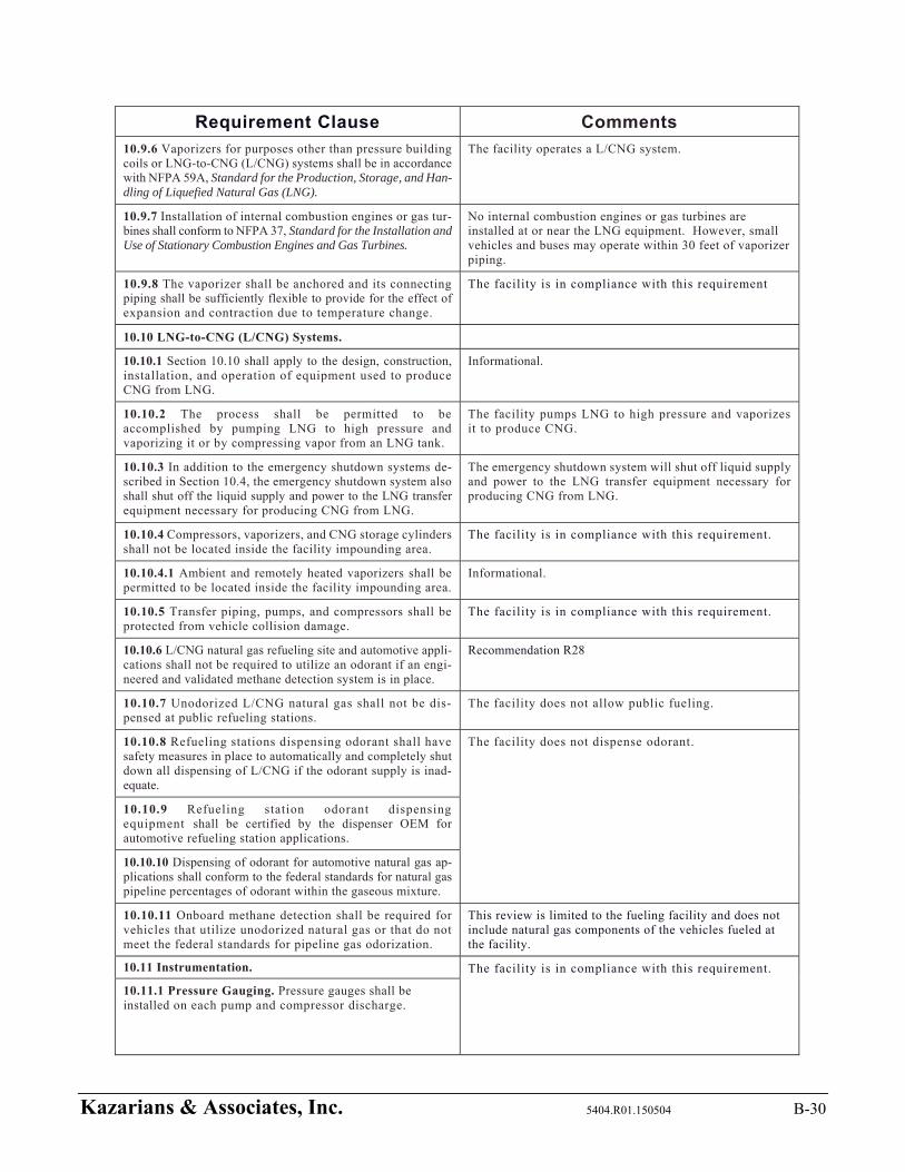
Kazarians & Associates, Inc. 5404.R01.150504 B-30
Requirement Clause Comments
10.9.6 Vaporizers for purposes other than pressure building coils or LNG-to-CNG (L/CNG) systems shall be in accordance with NFPA 59A, Standard for the Production, Storage, and Han-dling of Liquefied Natural Gas (LNG).
The facility operates a L/CNG system.
10.9.7 Installation of internal combustion engines or gas tur-bines shall conform to NFPA 37, Standard for the Installation and Use of Stationary Combustion Engines and Gas Turbines.
No internal combustion engines or gas turbines are installed at or near the LNG equipment. However, small vehicles and buses may operate within 30 feet of vaporizer piping.
10.9.8 The vaporizer shall be anchored and its connecting piping shall be sufficiently flexible to provide for the effect of expansion and contraction due to temperature change.
The facility is in compliance with this requirement
10.10 LNG-to-CNG (L/CNG) Systems.
10.10.1 Section 10.10 shall apply to the design, construction, installation, and operation of equipment used to produce CNG from LNG.
Informational.
10.10.2 The process shall be permitted to be accomplished by pumping LNG to high pressure and vaporizing it or by compressing vapor from an LNG tank.
The facility pumps LNG to high pressure and vaporizes it to produce CNG.
10.10.3 In addition to the emergency shutdown systems de-scribed in Section 10.4, the emergency shutdown system also shall shut off the liquid supply and power to the LNG transfer equipment necessary for producing CNG from LNG.
The emergency shutdown system will shut off liquid supply and power to the LNG transfer equipment necessary for producing CNG from LNG.
10.10.4 Compressors, vaporizers, and CNG storage cylinders shall not be located inside the facility impounding area.
The facility is in compliance with this requirement.
10.10.4.1 Ambient and remotely heated vaporizers shall be permitted to be located inside the facility impounding area.
Informational.
10.10.5 Transfer piping, pumps, and compressors shall be protected from vehicle collision damage.
The facility is in compliance with this requirement.
10.10.6 L/CNG natural gas refueling site and automotive appli-cations shall not be required to utilize an odorant if an engi-neered and validated methane detection system is in place.
Recommendation R28
10.10.7 Unodorized L/CNG natural gas shall not be dis-pensed at public refueling stations.
The facility does not allow public fueling.
10.10.8 Refueling stations dispensing odorant shall have safety measures in place to automatically and completely shut down all dispensing of L/CNG if the odorant supply is inad-equate.
The facility does not dispense odorant.
10.10.9 Refueling station odorant dispensing equipment shall be certified by the dispenser OEM for automotive refueling station applications.
10.10.10 Dispensing of odorant for automotive natural gas ap-plications shall conform to the federal standards for natural gas pipeline percentages of odorant within the gaseous mixture.
10.10.11 Onboard methane detection shall be required for vehicles that utilize unodorized natural gas or that do not meet the federal standards for pipeline gas odorization.
This review is limited to the fueling facility and does not include natural gas components of the vehicles fueled at the facility.
10.11 Instrumentation. The facility is in compliance with this requirement.
10.11.1 Pressure Gauging. Pressure gauges shall be installed on each pump and compressor discharge.
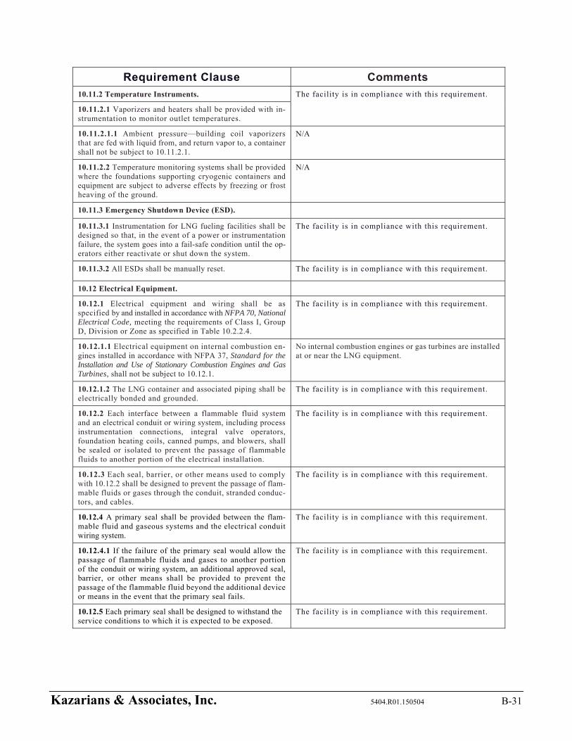
Kazarians & Associates, Inc. 5404.R01.150504 B-31
Requirement Clause Comments
10.11.2 Temperature Instruments. The facility is in compliance with this requirement.
10.11.2.1 Vaporizers and heaters shall be provided with in-strumentation to monitor outlet temperatures.
10.11.2.1.1 Ambient pressure—building coil vaporizers that are fed with liquid from, and return vapor to, a container shall not be subject to 10.11.2.1.
N/A
10.11.2.2 Temperature monitoring systems shall be provided where the foundations supporting cryogenic containers and equipment are subject to adverse effects by freezing or frost heaving of the ground.
N/A
10.11.3 Emergency Shutdown Device (ESD).
10.11.3.1 Instrumentation for LNG fueling facilities shall be designed so that, in the event of a power or instrumentation failure, the system goes into a fail-safe condition until the op-erators either reactivate or shut down the system.
The facility is in compliance with this requirement.
10.11.3.2 All ESDs shall be manually reset. The facility is in compliance with this requirement.
10.12 Electrical Equipment.
10.12.1 Electrical equipment and wiring shall be as specified by and installed in accordance with NFPA 70, National Electrical Code, meeting the requirements of Class I, Group D, Division or Zone as specified in Table 10.2.2.4.
The facility is in compliance with this requirement.
10.12.1.1 Electrical equipment on internal combustion en-gines installed in accordance with NFPA 37, Standard for the Installation and Use of Stationary Combustion Engines and Gas Turbines, shall not be subject to 10.12.1.
No internal combustion engines or gas turbines are installed at or near the LNG equipment.
10.12.1.2 The LNG container and associated piping shall be electrically bonded and grounded.
The facility is in compliance with this requirement.
10.12.2 Each interface between a flammable fluid system and an electrical conduit or wiring system, including process instrumentation connections, integral valve operators, foundation heating coils, canned pumps, and blowers, shall be sealed or isolated to prevent the passage of flammable fluids to another portion of the electrical installation.
The facility is in compliance with this requirement.
10.12.3 Each seal, barrier, or other means used to comply with 10.12.2 shall be designed to prevent the passage of flam-mable fluids or gases through the conduit, stranded conduc-tors, and cables.
The facility is in compliance with this requirement.
10.12.4 A primary seal shall be provided between the flam-mable fluid and gaseous systems and the electrical conduit wiring system.
The facility is in compliance with this requirement.
10.12.4.1 If the failure of the primary seal would allow the passage of flammable fluids and gases to another portion of the conduit or wiring system, an additional approved seal, barrier, or other means shall be provided to prevent the passage of the flammable fluid beyond the additional device or means in the event that the primary seal fails.
The facility is in compliance with this requirement.
10.12.5 Each primary seal shall be designed to withstand the service conditions to which it is expected to be exposed.
The facility is in compliance with this requirement.
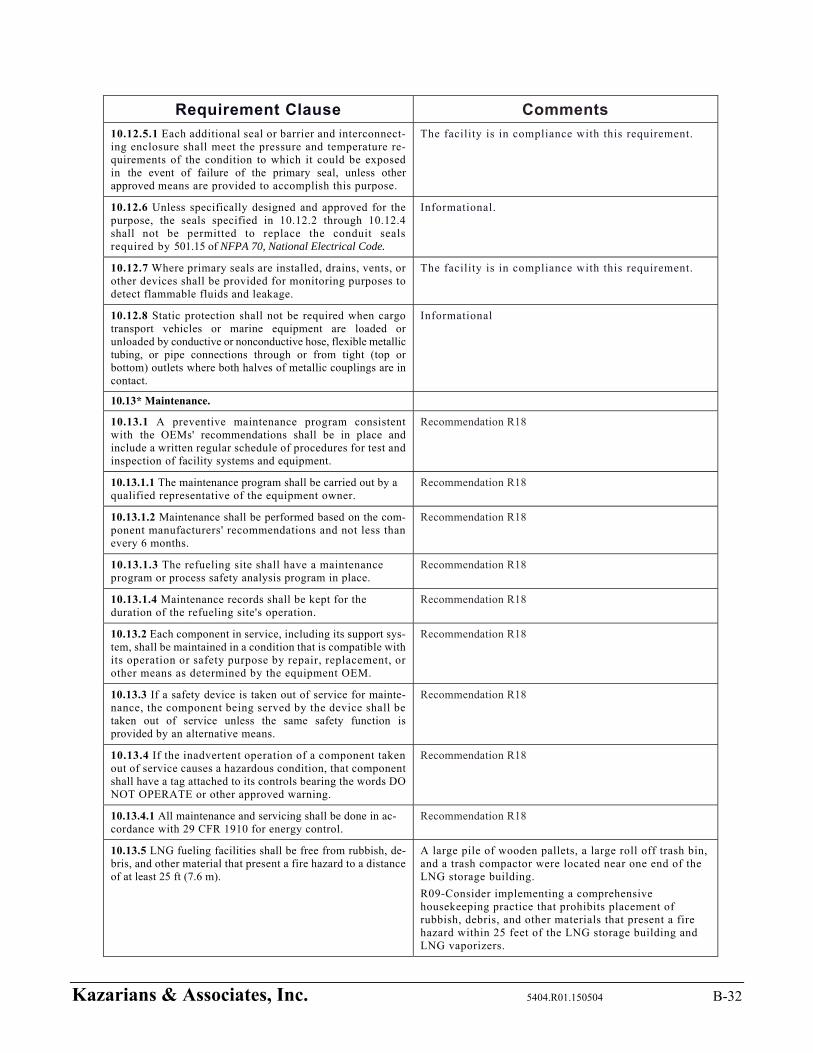
Kazarians & Associates, Inc. 5404.R01.150504 B-32
Requirement Clause Comments
10.12.5.1 Each additional seal or barrier and interconnect-ing enclosure shall meet the pressure and temperature re-quirements of the condition to which it could be exposed in the event of failure of the primary seal, unless other approved means are provided to accomplish this purpose.
The facility is in compliance with this requirement.
10.12.6 Unless specifically designed and approved for the purpose, the seals specified in 10.12.2 through 10.12.4 shall not be permitted to replace the conduit seals required by 501.15 of NFPA 70, National Electrical Code.
Informational.
10.12.7 Where primary seals are installed, drains, vents, or other devices shall be provided for monitoring purposes to detect flammable fluids and leakage.
The facility is in compliance with this requirement.
10.12.8 Static protection shall not be required when cargo transport vehicles or marine equipment are loaded or unloaded by conductive or nonconductive hose, flexible metallic tubing, or pipe connections through or from tight (top or bottom) outlets where both halves of metallic couplings are in contact.
Informational
10.13* Maintenance.
10.13.1 A preventive maintenance program consistent with the OEMs' recommendations shall be in place and include a written regular schedule of procedures for test and inspection of facility systems and equipment.
Recommendation R18
10.13.1.1 The maintenance program shall be carried out by a qualified representative of the equipment owner.
Recommendation R18
10.13.1.2 Maintenance shall be performed based on the com-ponent manufacturers' recommendations and not less than every 6 months.
Recommendation R18
10.13.1.3 The refueling site shall have a maintenance program or process safety analysis program in place.
Recommendation R18
10.13.1.4 Maintenance records shall be kept for the duration of the refueling site's operation.
Recommendation R18
10.13.2 Each component in service, including its support sys-tem, shall be maintained in a condition that is compatible with its operation or safety purpose by repair, replacement, or other means as determined by the equipment OEM.
Recommendation R18
10.13.3 If a safety device is taken out of service for mainte-nance, the component being served by the device shall be taken out of service unless the same safety function is provided by an alternative means.
Recommendation R18
10.13.4 If the inadvertent operation of a component taken out of service causes a hazardous condition, that component shall have a tag attached to its controls bearing the words DO NOT OPERATE or other approved warning.
Recommendation R18
10.13.4.1 All maintenance and servicing shall be done in ac-cordance with 29 CFR 1910 for energy control.
Recommendation R18
10.13.5 LNG fueling facilities shall be free from rubbish, de-bris, and other material that present a fire hazard to a distance of at least 25 ft (7.6 m).
A large pile of wooden pallets, a large roll off trash bin, and a trash compactor were located near one end of the LNG storage building.
R09-Consider implementing a comprehensive housekeeping practice that prohibits placement of rubbish, debris, and other materials that present a fire hazard within 25 feet of the LNG storage building and LNG vaporizers.
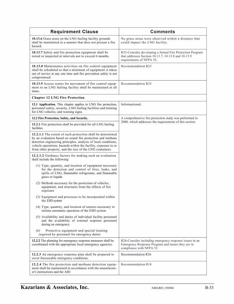
Kazarians & Associates, Inc. 5404.R01.150504 B-33
Requirement Clause Comments
10.13.6 Grass areas on the LNG fueling facility grounds shall be maintained in a manner that does not present a fire hazard.
No grass areas were observed within a distance that could impact the LNG facility.
10.13.7 Safety and fire protection equipment shall be tested or inspected at intervals not to exceed 6 months.
R25-Consider developing a formal Fire Protection Program that addresses Section 10.13.7, 10.13.8 and 10.13.9 requirements of NFPA 52.
10.13.8 Maintenance activities on fire control equipment shall be scheduled so that a minimum of equipment is taken out of service at any one time and fire prevention safety is not compromised.
Recommendation R25
10.13.9 Access routes for movement of fire control equip-ment to an LNG fueling facility shall be maintained at all times.
Recommendation R25
Chapter 12 LNG Fire Protection
12.1 Application. This chapter applies to LNG fire protection, personnel safety, security, LNG fueling facilities and training for LNG vehicles, and warning signs.
Informational.
12.2 Fire Protection, Safety, and Security. A comprehensive fire protection study was performed in 2000, which addresses the requirements of this section.
12.2.1 Fire protection shall be provided for all LNG fueling facilities.
12.2.1.1 The extent of such protection shall be determined by an evaluation based on sound fire protection and methane detection engineering principles, analysis of local conditions, vehicle operations, hazards within the facility, exposure to or from other property, and the size of the LNG containers.
12.2.1.2 Guidance factors for making such an evaluation shall include the following:
(1) Type, quantity, and location of equipment necessary for the detection and control of fires, leaks, and spills of LNG, flammable refrigerants, and flammable gases or liquids
(2) Methods necessary for the protection of vehicles, equipment, and structures from the effects of fire exposure
(3) Equipment and processes to be incorporated within the ESD system
(4) Type, quantity, and location of sensors necessary to initiate automatic operation of the ESD system
(5) Availability and duties of individual facility personnel and the availability of external response personnel during an emergency
(6) Protective equipment and special training required by personnel for emergency duties
12.2.2 The planning for emergency response measures shall be coordinated with the appropriate local emergency agencies.
R26-Consider including emergency response issues in an Emergency Response Program and insure they are in compliance with NFPA 52.
12.2.3 An emergency response plan shall be prepared to cover foreseeable emergency conditions.
Recommendation R26
12.2.4 The fire protection and methane detection equip-ment shall be maintained in accordance with the manufactur-er's instructions and the AHJ
Recommendation R18

Kazarians & Associates, Inc. 5404.R01.150504 B-34
Requirement Clause Comments
12.3 Ignition Source Control. The facility is in compliance with this requirement.
12.3.1 Smoking and ignition sources shall be prohibited, ex-cept in accordance with 12.3.2.
12.3.2 Welding, oxygen—acetylene cutting, and similar operations shall be conducted only when and where specifically authorized and in accordance with the provisions of NFPA 51B, Standard for Fire Prevention During Welding Cutting, and Other Hot Work.
Recommendation R22
12.3.3 Vehicles and other mobile equipment that constitute a potential ignition source shall be prohibited except where spe-cifically authorized and under constant supervision or when at a transfer point specifically for the purpose of transfer.
The facility is in compliance with this requirement.
12.3.4 Vehicles delivering LNG to the facility or vehicles being fueled from the facility shall not be considered sources of ignition.
Informational.
12.3.5 Vehicles containing fuel-fired equipment (e.g., recre-ational vehicles and catering trucks) shall be considered a source of ignition unless all sources of ignition such as pilot lights, electric igniters, burners, electrical appliances, and engines located on the vehicle being refueled are shut off completely before entering an area where ignition sources are prohibited.
The facility is in compliance with this requirement.
12.4 Personnel Safety and Training. Recommendation R19 – Develop a formal training program for all personnel that work with CLNG system to comply with Section 12.4 of NFPA 52. 12.4.1 Qualification of Personnel. All persons employed in
handling and dispensing LNG shall be trained in handling and operating duties and procedures.
12.4.2 Protective clothing, face shield/goggles, and gloves shall be provided for all operators dispensing and handling LNG.
Recommendation R24-The written procedures that address CLNG and bus fueling related operations shall explicitly address Personal Protective Equipment (PPE) requirements and usage.
12.4.2.1 Requirements, as specified in 12.4.2, shall be permit-ted to be excluded where equipment is demonstrated to operate without exposing operators to release of LNG or cold gases.
Informational
12.4.3 Training shall be conducted upon employment and every 2 years thereafter.
Recommendation R19
12.4.4 Training shall include the following: Recommendation R19
(1) Information on the nature, properties, and hazards of LNG in both the liquid and gaseous phases
(2) Specific instructions on the facility equipment to be used
(3) Information on materials that are compatible for use with LNG
(4) Use and care of protective equipment and clothing
(5) Standard first aid and self-aid instruction
(6) Response to emergency situations such as fires, leaks, and spills
(7) Good housekeeping practices
(8) Emergency response plan as required in 12.2.3
(9) Evacuation and fire drills
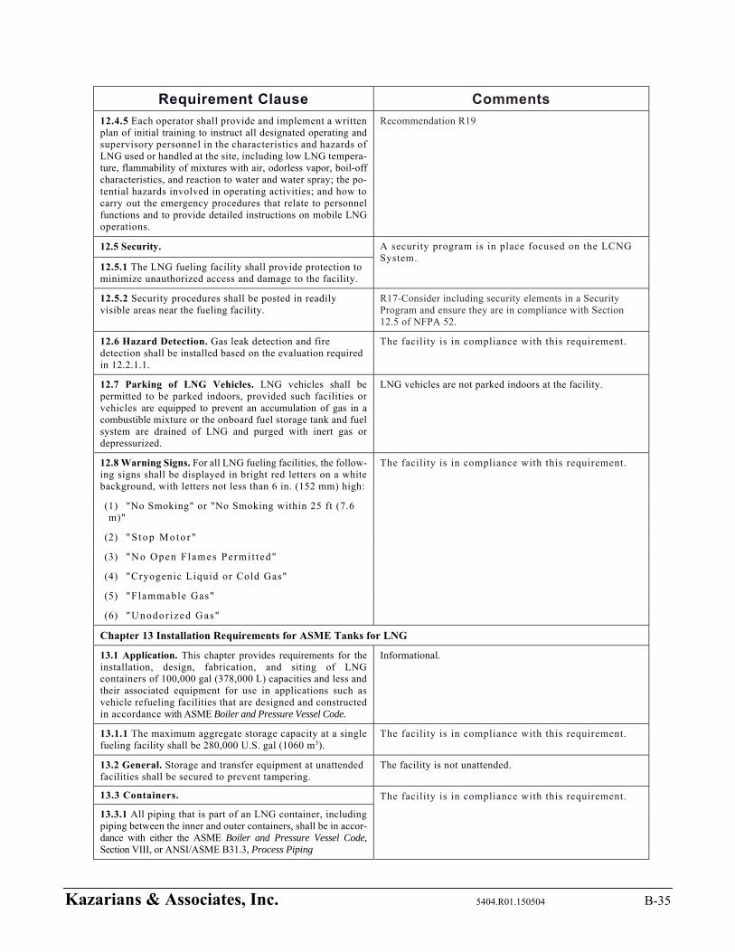
Kazarians & Associates, Inc. 5404.R01.150504 B-35
Requirement Clause Comments
12.4.5 Each operator shall provide and implement a written plan of initial training to instruct all designated operating and supervisory personnel in the characteristics and hazards of LNG used or handled at the site, including low LNG tempera-ture, flammability of mixtures with air, odorless vapor, boil-off characteristics, and reaction to water and water spray; the po-tential hazards involved in operating activities; and how to carry out the emergency procedures that relate to personnel functions and to provide detailed instructions on mobile LNG operations.
Recommendation R19
12.5 Security. A security program is in place focused on the LCNG System.
12.5.1 The LNG fueling facility shall provide protection to minimize unauthorized access and damage to the facility.
12.5.2 Security procedures shall be posted in readily visible areas near the fueling facility.
R17-Consider including security elements in a Security Program and ensure they are in compliance with Section 12.5 of NFPA 52.
12.6 Hazard Detection. Gas leak detection and fire detection shall be installed based on the evaluation required in 12.2.1.1.
The facility is in compliance with this requirement.
12.7 Parking of LNG Vehicles. LNG vehicles shall be permitted to be parked indoors, provided such facilities or vehicles are equipped to prevent an accumulation of gas in a combustible mixture or the onboard fuel storage tank and fuel system are drained of LNG and purged with inert gas or depressurized.
LNG vehicles are not parked indoors at the facility.
12.8 Warning Signs. For all LNG fueling facilities, the follow-ing signs shall be displayed in bright red letters on a white background, with letters not less than 6 in. (152 mm) high:
The facility is in compliance with this requirement.
(1) "No Smoking" or "No Smoking within 25 ft (7.6 m)"
(2) " S t o p M o t o r "
(3) "No Open F lames Permi t t ed"
(4) "Cryogenic Liquid or Cold Gas"
(5) "Flammable Gas"
(6) "Unodor ized Gas"
Chapter 13 Installation Requirements for ASME Tanks for LNG
13.1 Application. This chapter provides requirements for the installation, design, fabrication, and siting of LNG containers of 100,000 gal (378,000 L) capacities and less and their associated equipment for use in applications such as vehicle refueling facilities that are designed and constructed in accordance with ASME Boiler and Pressure Vessel Code.
Informational.
13.1.1 The maximum aggregate storage capacity at a single fueling facility shall be 280,000 U.S. gal (1060 m3).
The facility is in compliance with this requirement.
13.2 General. Storage and transfer equipment at unattended facilities shall be secured to prevent tampering.
The facility is not unattended.
13.3 Containers. The facility is in compliance with this requirement.
13.3.1 All piping that is part of an LNG container, including piping between the inner and outer containers, shall be in accor-dance with either the ASME Boiler and Pressure Vessel Code, Section VIII, or ANSI/ASME B31.3, Process Piping
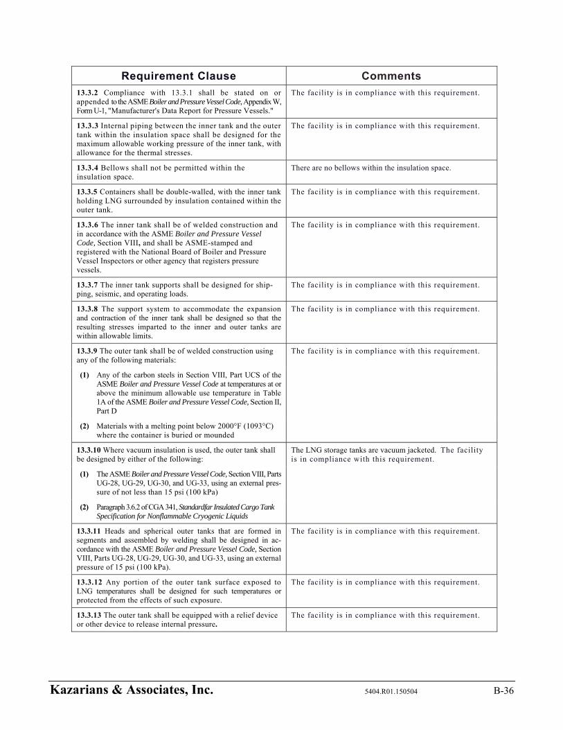
Kazarians & Associates, Inc. 5404.R01.150504 B-36
Requirement Clause Comments
13.3.2 Compliance with 13.3.1 shall be stated on or appended to the ASME Boiler and Pressure Vessel Code, Appendix W, Form U-1, "Manufacturer's Data Report for Pressure Vessels."
The facility is in compliance with this requirement.
13.3.3 Internal piping between the inner tank and the outer tank within the insulation space shall be designed for the maximum allowable working pressure of the inner tank, with allowance for the thermal stresses.
The facility is in compliance with this requirement.
13.3.4 Bellows shall not be permitted within the insulation space.
There are no bellows within the insulation space.
13.3.5 Containers shall be double-walled, with the inner tank holding LNG surrounded by insulation contained within the outer tank.
The facility is in compliance with this requirement.
13.3.6 The inner tank shall be of welded construction and in accordance with the ASME Boiler and Pressure Vessel Code, Section VIII, and shall be ASME-stamped and registered with the National Board of Boiler and Pressure Vessel Inspectors or other agency that registers pressure vessels.
The facility is in compliance with this requirement.
13.3.7 The inner tank supports shall be designed for ship-ping, seismic, and operating loads.
The facility is in compliance with this requirement.
13.3.8 The support system to accommodate the expansion and contraction of the inner tank shall be designed so that the resulting stresses imparted to the inner and outer tanks are within allowable limits.
The facility is in compliance with this requirement.
13.3.9 The outer tank shall be of welded construction using any of the following materials:
The facility is in compliance with this requirement.
(1) Any of the carbon steels in Section VIII, Part UCS of the ASME Boiler and Pressure Vessel Code at temperatures at or above the minimum allowable use temperature in Table 1A of the ASME Boiler and Pressure Vessel Code, Section II, Part D
(2) Materials with a melting point below 2000°F (1093°C) where the container is buried or mounded
13.3.10 Where vacuum insulation is used, the outer tank shall be designed by either of the following:
The LNG storage tanks are vacuum jacketed. The facility is in compliance with this requirement.
(1) The ASME Boiler and Pressure Vessel Code, Section VIII, Parts UG-28, UG-29, UG-30, and UG-33, using an external pres-sure of not less than 15 psi (100 kPa)
(2) Paragraph 3.6.2 of CGA 341, Standardfar Insulated Cargo Tank Specification for Nonflammable Cryogenic Liquids
13.3.11 Heads and spherical outer tanks that are formed in segments and assembled by welding shall be designed in ac-cordance with the ASME Boiler and Pressure Vessel Code, Section VIII, Parts UG-28, UG-29, UG-30, and UG-33, using an external pressure of 15 psi (100 kPa).
The facility is in compliance with this requirement.
13.3.12 Any portion of the outer tank surface exposed to LNG temperatures shall be designed for such temperatures or protected from the effects of such exposure.
The facility is in compliance with this requirement.
13.3.13 The outer tank shall be equipped with a relief device or other device to release internal pressure.
The facility is in compliance with this requirement.
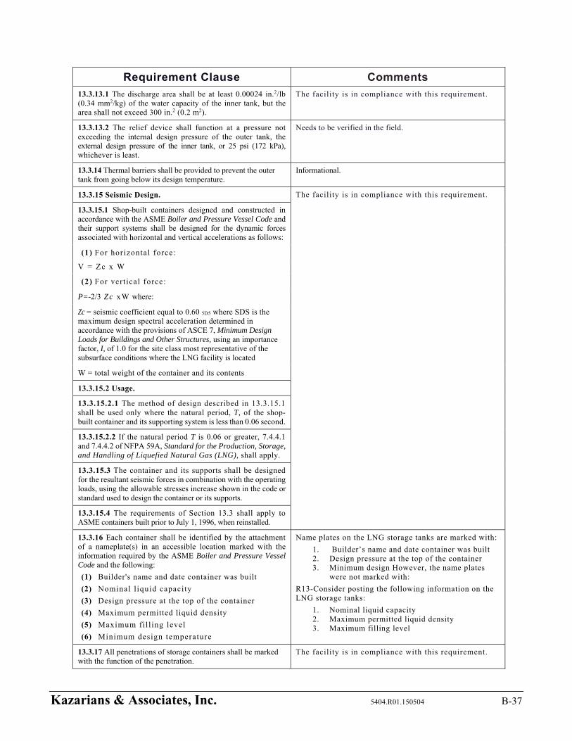
Kazarians & Associates, Inc. 5404.R01.150504 B-37
Requirement Clause Comments
13.3.13.1 The discharge area shall be at least 0.00024 in.2/lb (0.34 mm2/kg) of the water capacity of the inner tank, but the area shall not exceed 300 in.2 (0.2 m2).
The facility is in compliance with this requirement.
13.3.13.2 The relief device shall function at a pressure not exceeding the internal design pressure of the outer tank, the external design pressure of the inner tank, or 25 psi (172 kPa), whichever is least.
Needs to be verified in the field.
13.3.14 Thermal barriers shall be provided to prevent the outer tank from going below its design temperature.
Informational.
13.3.15 Seismic Design. The facility is in compliance with this requirement.
13.3.15.1 Shop-built containers designed and constructed in accordance with the ASME Boiler and Pressure Vessel Code and their support systems shall be designed for the dynamic forces associated with horizontal and vertical accelerations as follows:
(1) For horizontal force:
V = Zc x W
(2) For vert ical force:
P=-2/3 Zc xW where:
Zc = seismic coefficient equal to 0.60 5D5 where SDS is the maximum design spectral acceleration determined in accordance with the provisions of ASCE 7, Minimum Design Loads for Buildings and Other Structures, using an importance factor, I, of 1.0 for the site class most representative of the subsurface conditions where the LNG facility is located
W = total weight of the container and its contents
13.3.15.2 Usage.
13.3.15.2.1 The method of design described in 13.3.15.1 shall be used only where the natural period, T, of the shop-built container and its supporting system is less than 0.06 second.
13.3.15.2.2 If the natural period T is 0.06 or greater, 7.4.4.1 and 7.4.4.2 of NFPA 59A, Standard for the Production, Storage, and Handling of Liquefied Natural Gas (LNG), shall apply.
13.3.15.3 The container and its supports shall be designed for the resultant seismic forces in combination with the operating loads, using the allowable stresses increase shown in the code or standard used to design the container or its supports.
13.3.15.4 The requirements of Section 13.3 shall apply to ASME containers built prior to July 1, 1996, when reinstalled.
13.3.16 Each container shall be identified by the attachment of a nameplate(s) in an accessible location marked with the information required by the ASME Boiler and Pressure Vessel Code and the following:
(1) Builder's name and date container was built
(2) Nominal l iquid capacity
(3) Design pressure at the top of the container
(4) Maximum permitted liquid density
(5) Maximum fil l ing level
(6) Minimum design temperature
Name plates on the LNG storage tanks are marked with:
1. Builder’s name and date container was built 2. Design pressure at the top of the container 3. Minimum design However, the name plates
were not marked with:
R13-Consider posting the following information on the LNG storage tanks:
1. Nominal liquid capacity 2. Maximum permitted liquid density 3. Maximum filling level
13.3.17 All penetrations of storage containers shall be marked with the function of the penetration.
The facility is in compliance with this requirement.
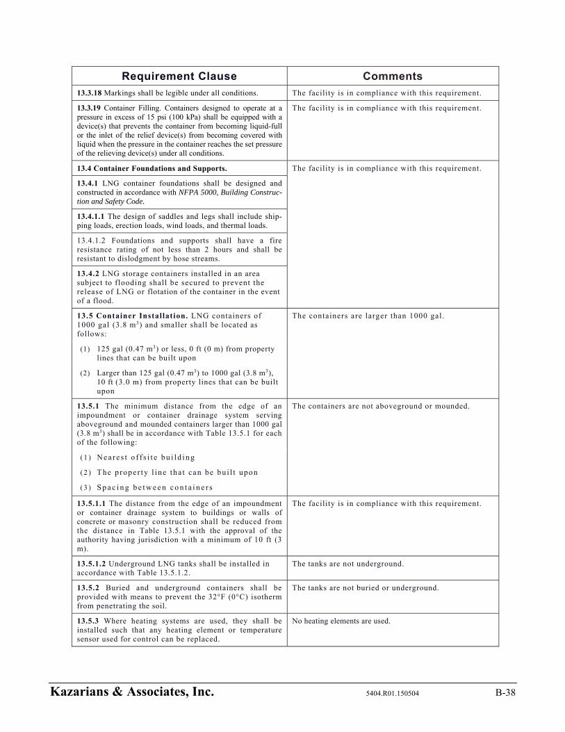
Kazarians & Associates, Inc. 5404.R01.150504 B-38
Requirement Clause Comments
13.3.18 Markings shall be legible under all conditions. The facility is in compliance with this requirement.
13.3.19 Container Filling. Containers designed to operate at a pressure in excess of 15 psi (100 kPa) shall be equipped with a device(s) that prevents the container from becoming liquid-full or the inlet of the relief device(s) from becoming covered with liquid when the pressure in the container reaches the set pressure of the relieving device(s) under all conditions.
The facility is in compliance with this requirement.
13.4 Container Foundations and Supports. The facility is in compliance with this requirement.
13.4.1 LNG container foundations shall be designed and constructed in accordance with NFPA 5000, Building Construc-tion and Safety Code.
13.4.1.1 The design of saddles and legs shall include ship-ping loads, erection loads, wind loads, and thermal loads.
13.4.1.2 Foundations and supports shall have a fire resistance rating of not less than 2 hours and shall be resistant to dislodgment by hose streams.
13.4.2 LNG storage containers installed in an area subject to flooding shall be secured to prevent the release of LNG or flotation of the container in the event of a flood.
13.5 Container Installation. LNG containers of 1000 gal (3.8 m3) and smaller shall be located as follows:
The containers are larger than 1000 gal.
(1) 125 gal (0.47 m3) or less, 0 ft (0 m) from property lines that can be built upon
(2) Larger than 125 gal (0.47 m3) to 1000 gal (3.8 m3), 10 ft (3.0 m) from property lines that can be built upon
13.5.1 The minimum distance from the edge of an impoundment or container drainage system serving aboveground and mounded containers larger than 1000 gal (3.8 m3) shall be in accordance with Table 13.5.1 for each of the following:
The containers are not aboveground or mounded.
( 1 ) N e a r e s t o f f s i t e b u i l d i n g
( 2 ) The p roper ty l ine tha t can be bu i l t upon
( 3 ) S p a c i n g b e t w e e n c o n t a i n e r s
13.5.1.1 The distance from the edge of an impoundment or container drainage system to buildings or walls of concrete or masonry construction shall be reduced from the distance in Table 13.5.1 with the approval of the authority having jurisdiction with a minimum of 10 ft (3 m).
The facility is in compliance with this requirement.
13.5.1.2 Underground LNG tanks shall be installed in accordance with Table 13.5.1.2.
The tanks are not underground.
13.5.2 Buried and underground containers shall be provided with means to prevent the 32°F (0°C) isotherm from penetrating the soil.
The tanks are not buried or underground.
13.5.3 Where heating systems are used, they shall be installed such that any heating element or temperature sensor used for control can be replaced.
No heating elements are used.
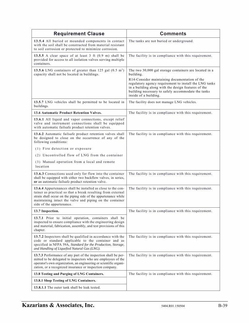
Kazarians & Associates, Inc. 5404.R01.150504 B-39
Requirement Clause Comments
13.5.4 All buried or mounded components in contact with the soil shall be constructed from material resistant to soil corrosion or protected to minimize corrosion.
The tanks are not buried or underground.
13.5.5 A clear space of at least 3 ft (0.9 m) shall be provided for access to all isolation valves serving multiple containers.
The facility is in compliance with this requirement.
13.5.6 LNG containers of greater than 125 gal (0.5 m3) capacity shall not be located in buildings.
The two 30,000 gal storage containers are located in a building.
R14-Consider maintaining documentation of the regulatory agency requirement to install the LNG tanks in a building along with the design features of the building necessary to safely accommodate the tanks inside of a building.
13.5.7 LNG vehicles shall be permitted to be located in buildings.
The facility does not manage LNG vehicles.
13.6 Automatic Product Retention Valves. The facility is in compliance with this requirement.
13.6.1 All liquid and vapor connections, except relief valve and instrument connections shall be equipped with automatic failsafe product retention valves.
13.6.2 Automatic failsafe product retention valves shall be designed to close on the occurrence of any of the following conditions:
The facility is in compliance with this requirement.
( 1 ) F i r e d e t e c t i o n o r e x p o s u r e
( 2 ) Uncont ro l led f low of LNG f rom the conta iner
( 3 ) Manual operat ion from a local and remote locat ion
13.6.3 Connections used only for flow into the container shall be equipped with either two backflow valves, in series, or an automatic failsafe product retention valve.
The facility is in compliance with this requirement.
13.6.4 Appurtenances shall be installed as close to the con-tainer as practical so that a break resulting from external strain shall occur on the piping side of the appurtenance while maintaining intact the valve and piping on the container side of the appurtenance.
The facility is in compliance with this requirement.
13.7 Inspection. The facility is in compliance with this requirement.
13.7.1 Prior to initial operation, containers shall be inspected to ensure compliance with the engineering design and material, fabrication, assembly, and test provisions of this chapter.
13.7.2 Inspectors shall be qualified in accordance with the code or standard applicable to the container and as specified in NFPA 59A, Standard for the Production, Storage, and Handling of Liquefied Natural Gas (LNG).
The facility is in compliance with this requirement.
13.7.3 Performance of any part of the inspection shall be per-mitted to be delegated to inspectors who are employees of the operator's own organization, an engineering or scientific organi-zation, or a recognized insurance or inspection company.
The facility is in compliance with this requirement.
13.8 Testing and Purging of LNG Containers. The facility is in compliance with this requirement.
13.8.1 Shop Testing of LNG Containers.
13.8.1.1 The outer tank shall be leak tested.
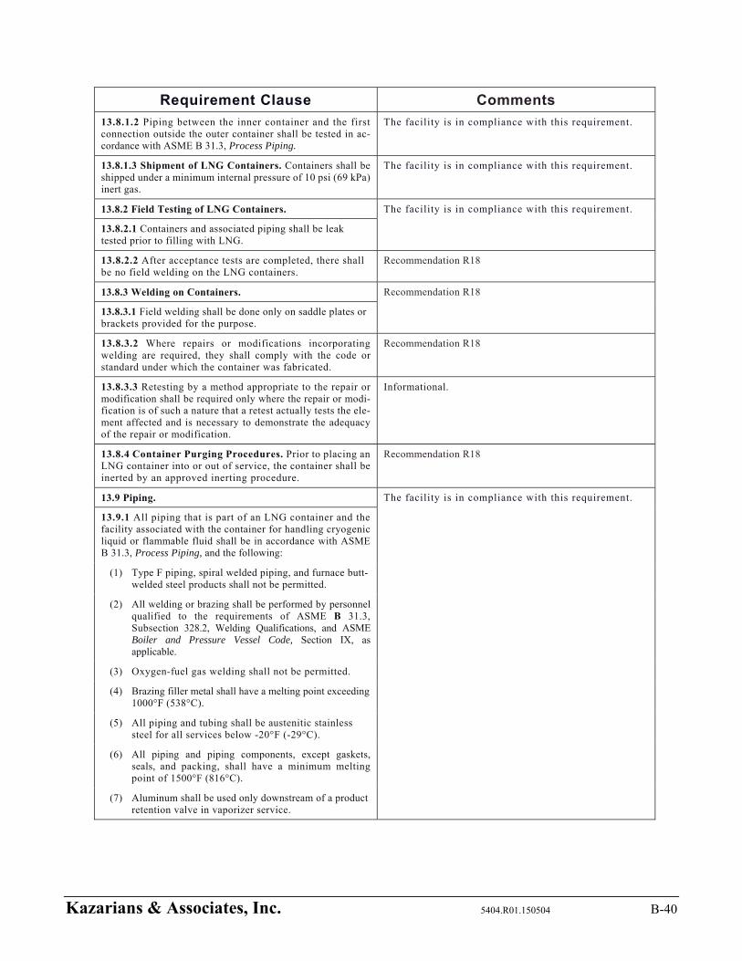
Kazarians & Associates, Inc. 5404.R01.150504 B-40
Requirement Clause Comments
13.8.1.2 Piping between the inner container and the first connection outside the outer container shall be tested in ac-cordance with ASME B 31.3, Process Piping.
The facility is in compliance with this requirement.
13.8.1.3 Shipment of LNG Containers. Containers shall be shipped under a minimum internal pressure of 10 psi (69 kPa) inert gas.
The facility is in compliance with this requirement.
13.8.2 Field Testing of LNG Containers. The facility is in compliance with this requirement.
13.8.2.1 Containers and associated piping shall be leak tested prior to filling with LNG.
13.8.2.2 After acceptance tests are completed, there shall be no field welding on the LNG containers.
Recommendation R18
13.8.3 Welding on Containers. Recommendation R18
13.8.3.1 Field welding shall be done only on saddle plates or brackets provided for the purpose.
13.8.3.2 Where repairs or modifications incorporating welding are required, they shall comply with the code or standard under which the container was fabricated.
Recommendation R18
13.8.3.3 Retesting by a method appropriate to the repair or modification shall be required only where the repair or modi-fication is of such a nature that a retest actually tests the ele-ment affected and is necessary to demonstrate the adequacy of the repair or modification.
Informational.
13.8.4 Container Purging Procedures. Prior to placing an LNG container into or out of service, the container shall be inerted by an approved inerting procedure.
Recommendation R18
13.9 Piping. The facility is in compliance with this requirement.
13.9.1 All piping that is part of an LNG container and the facility associated with the container for handling cryogenic liquid or flammable fluid shall be in accordance with ASME B 31.3, Process Piping, and the following:
(1) Type F piping, spiral welded piping, and furnace butt-welded steel products shall not be permitted.
(2) All welding or brazing shall be performed by personnel qualified to the requirements of ASME B 31.3, Subsection 328.2, Welding Qualifications, and ASME Boiler and Pressure Vessel Code, Section IX, as applicable.
(3) Oxygen-fuel gas welding shall not be permitted.
(4) Brazing filler metal shall have a melting point exceeding 1000°F (538°C).
(5) All piping and tubing shall be austenitic stainless steel for all services below -20°F (-29°C).
(6) All piping and piping components, except gaskets, seals, and packing, shall have a minimum melting point of 1500°F (816°C).
(7) Aluminum shall be used only downstream of a product retention valve in vaporizer service.
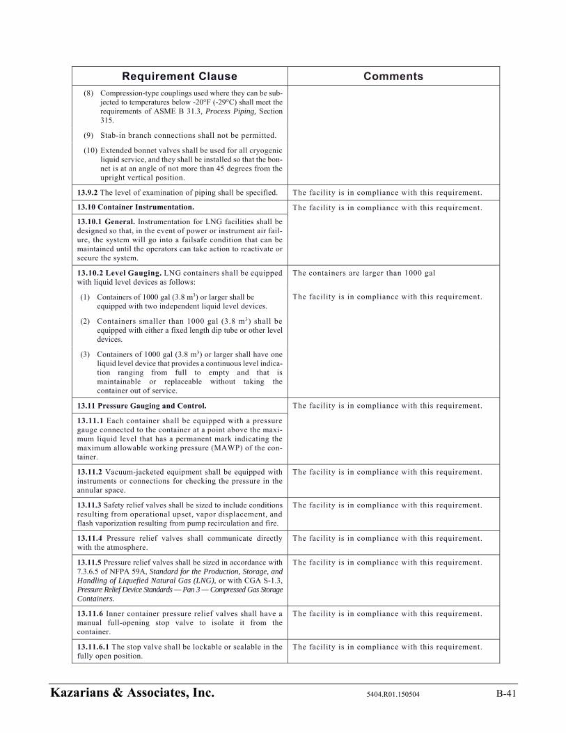
Kazarians & Associates, Inc. 5404.R01.150504 B-41
Requirement Clause Comments
(8) Compression-type couplings used where they can be sub-jected to temperatures below -20°F (-29°C) shall meet the requirements of ASME B 31.3, Process Piping, Section 315.
(9) Stab-in branch connections shall not be permitted.
(10) Extended bonnet valves shall be used for all cryogenic liquid service, and they shall be installed so that the bon-net is at an angle of not more than 45 degrees from the upright vertical position.
13.9.2 The level of examination of piping shall be specified. The facility is in compliance with this requirement.
13.10 Container Instrumentation. The facility is in compliance with this requirement.
13.10.1 General. Instrumentation for LNG facilities shall be designed so that, in the event of power or instrument air fail-ure, the system will go into a failsafe condition that can be maintained until the operators can take action to reactivate or secure the system.
13.10.2 Level Gauging. LNG containers shall be equipped with liquid level devices as follows:
The containers are larger than 1000 gal
The facility is in compliance with this requirement. (1) Containers of 1000 gal (3.8 m3) or larger shall be equipped with two independent liquid level devices.
(2) Containers smaller than 1000 gal (3.8 m3) shall be equipped with either a fixed length dip tube or other level devices.
(3) Containers of 1000 gal (3.8 m3) or larger shall have one liquid level device that provides a continuous level indica-tion ranging from full to empty and that is maintainable or replaceable without taking the container out of service.
13.11 Pressure Gauging and Control. The facility is in compliance with this requirement.
13.11.1 Each container shall be equipped with a pressure gauge connected to the container at a point above the maxi-mum liquid level that has a permanent mark indicating the maximum allowable working pressure (MAWP) of the con-tainer.
13.11.2 Vacuum-jacketed equipment shall be equipped with instruments or connections for checking the pressure in the annular space.
The facility is in compliance with this requirement.
13.11.3 Safety relief valves shall be sized to include conditions resulting from operational upset, vapor displacement, and flash vaporization resulting from pump recirculation and fire.
The facility is in compliance with this requirement.
13.11.4 Pressure relief valves shall communicate directly with the atmosphere.
The facility is in compliance with this requirement.
13.11.5 Pressure relief valves shall be sized in accordance with 7.3.6.5 of NFPA 59A, Standard for the Production, Storage, and Handling of Liquefied Natural Gas (LNG), or with CGA S-1.3, Pressure Relief Device Standards — Pan 3 — Compressed Gas Storage Containers.
The facility is in compliance with this requirement.
13.11.6 Inner container pressure relief valves shall have a manual full-opening stop valve to isolate it from the container.
The facility is in compliance with this requirement.
13.11.6.1 The stop valve shall be lockable or sealable in the fully open position.
The facility is in compliance with this requirement.

Kazarians & Associates, Inc. 5404.R01.150504 B-42
Requirement Clause Comments
13.11.6.2 The installation of pressure relief valves shall allow each relief valve to be isolated individually for testing or main-tenance while maintaining the full relief capacities determined in 7.3.6.5 of NFPA 59A, Standard for the Production, Storage, and Handling of Liquefied Natural Gas (LNG).
The facility is in compliance with this requirement.
13.11.6.3 Where only one pressure relief valve is required, either a full-port opening three-way valve used under the pres-sure relief valve and its required spare or individual valves be-neath each pressure relief valve shall be installed.
The facility is in compliance with this requirement.
13.11.7 Stop valves under individual safety relief valves shall be locked or sealed when opened and shall not be opened or closed except by an authorized person.
The facility is in compliance with this requirement.
13.11.8 Safety relief valve discharge stacks or vents shall be designed and installed to prevent an accumulation of water, ice, snow, or other foreign matter and, if arranged to dis-charge directly into the atmosphere, shall discharge vertically upward.
The facility is in compliance with this requirement.

Appendix C – Industry Incidents Summary

Kazarians & Associates, Inc. 5404.R01.150504 C-1
Appendix C - LNG Industry Incidents
No. Incident
Information and Reference
Initiating Cause and Category
Brief Description of Incident1 Comments Applicable
to Omnitrans
1 Cleveland, Ohio; LNG Peakshaving Facility; October 1944 128 fatalities, 225 injuries “Safety History of International LNG Operations”, Rev. 12, CH IV International, February 8, 2012.
Complete tank failure due to low temperature embrittlement due to construction with improper material for service
On October 20, 1944, the tanks had been filled to capacity in readiness for the coming winter months. About 2:15 PM, the cylindrical tank suddenly failed releasing all of its contents into the nearby streets and sewers of Cleveland. The cloud promptly ignited and a fire ensued which engulfed the nearby tanks, residences and commercial establishments. After about 20 minutes, when the initial fire had nearly died down, the sphere nearest to the cylindrical tank toppled over and released its contents. 9,400 gallons of LNG immediately evaporated and ignited. In all, 128 people were killed and 225 injured. The area directly involved was about three-quarters of a square mile (475 acres) of which an area of about 30 acres was completely devastated.
Tank was built with low nickel content (3.5%) alloy (inappropriate for LNG storage). Storage Tanks at OmniTrans are constructed with proper materials. (SA 553) 8-9% nickel content Modelling: Complete tank failure of one of the storage tanks will be modeled. Applicable: This scenario is not applicable to Omnitrans because any errors in construction material would have been discovered by now.
No
2 Arzew, Algeria, 1964 AND 1965. No injuries “Safety History of International LNG Operations”, Rev. 12,
Lightning strike during venting
During loading operations, lightning struck the forward vent riser of the Methane Progress and ignited vapor which was being routinely vented through the ship venting system. A similar event happened early in 1965 while the vessel was at sea shortly after leaving Arzew. In both cases,
Lightning strikes are not common in the area. Venting during offloading only occurs for a short amount of time. Modelling: Relief valve Applicable: Yes, no injuries.
Yes
1 All entries in this column have been adopted from the references noted in the first column.
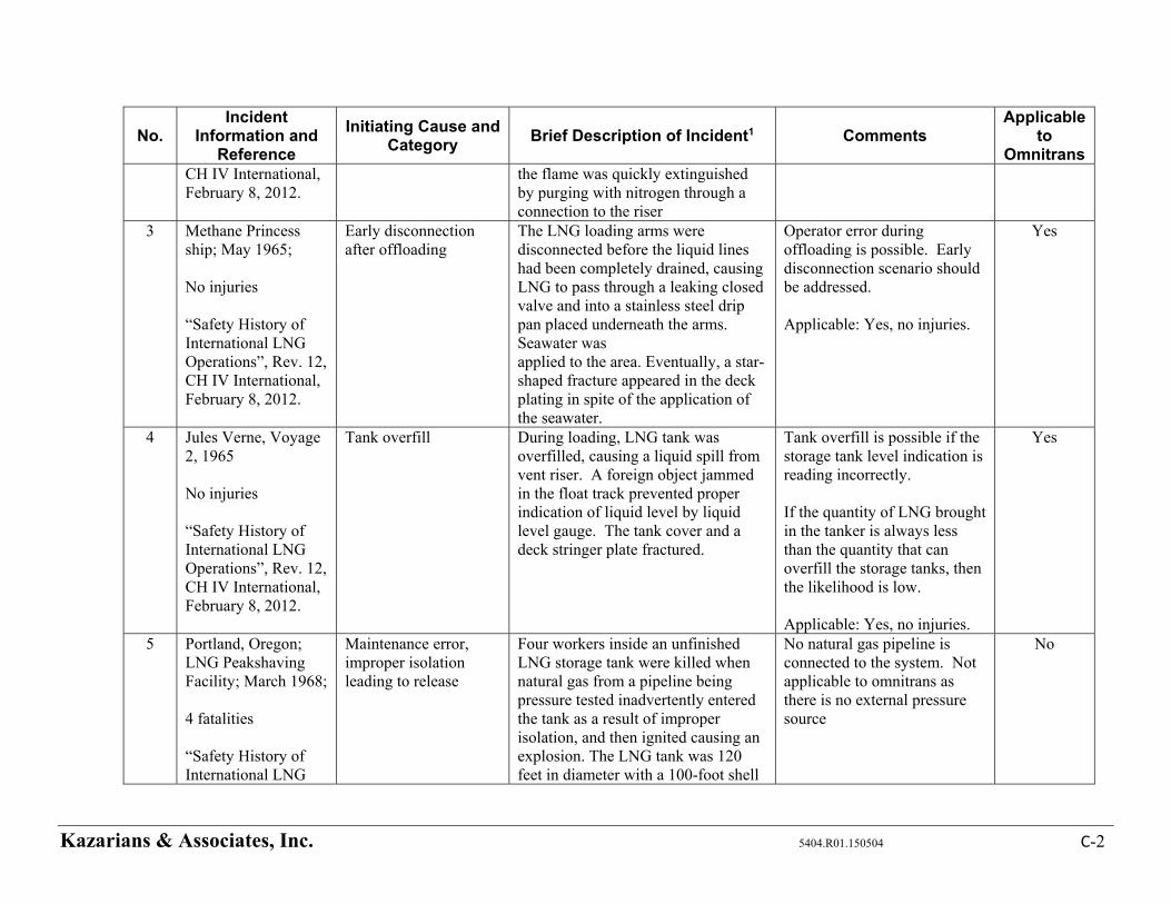
Kazarians & Associates, Inc. 5404.R01.150504 C-2
No. Incident
Information and Reference
Initiating Cause and Category
Brief Description of Incident1 Comments Applicable
to Omnitrans
CH IV International, February 8, 2012.
the flame was quickly extinguished by purging with nitrogen through a connection to the riser
3 Methane Princess ship; May 1965; No injuries “Safety History of International LNG Operations”, Rev. 12, CH IV International, February 8, 2012.
Early disconnection after offloading
The LNG loading arms were disconnected before the liquid lines had been completely drained, causing LNG to pass through a leaking closed valve and into a stainless steel drip pan placed underneath the arms. Seawater was applied to the area. Eventually, a star-shaped fracture appeared in the deck plating in spite of the application of the seawater.
Operator error during offloading is possible. Early disconnection scenario should be addressed. Applicable: Yes, no injuries.
Yes
4 Jules Verne, Voyage 2, 1965 No injuries “Safety History of International LNG Operations”, Rev. 12, CH IV International, February 8, 2012.
Tank overfill During loading, LNG tank was overfilled, causing a liquid spill from vent riser. A foreign object jammed in the float track prevented proper indication of liquid level by liquid level gauge. The tank cover and a deck stringer plate fractured.
Tank overfill is possible if the storage tank level indication is reading incorrectly. If the quantity of LNG brought in the tanker is always less than the quantity that can overfill the storage tanks, then the likelihood is low. Applicable: Yes, no injuries.
Yes
5 Portland, Oregon; LNG Peakshaving Facility; March 1968; 4 fatalities “Safety History of International LNG
Maintenance error, improper isolation leading to release
Four workers inside an unfinished LNG storage tank were killed when natural gas from a pipeline being pressure tested inadvertently entered the tank as a result of improper isolation, and then ignited causing an explosion. The LNG tank was 120 feet in diameter with a 100-foot shell
No natural gas pipeline is connected to the system. Not applicable to omnitrans as there is no external pressure source
No
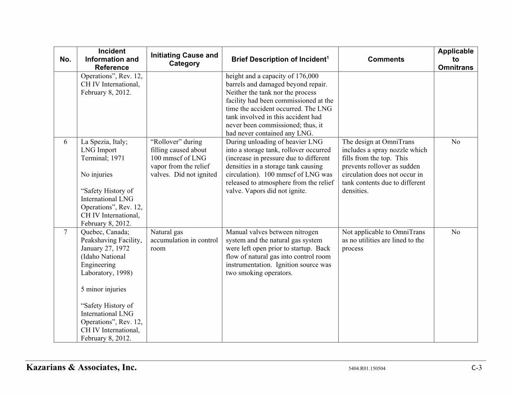
Kazarians & Associates, Inc. 5404.R01.150504 C-3
No. Incident
Information and Reference
Initiating Cause and Category
Brief Description of Incident1 Comments Applicable
to Omnitrans
Operations”, Rev. 12, CH IV International, February 8, 2012.
height and a capacity of 176,000 barrels and damaged beyond repair. Neither the tank nor the process facility had been commissioned at the time the accident occurred. The LNG tank involved in this accident had never been commissioned; thus, it had never contained any LNG.
6 La Spezia, Italy; LNG Import Terminal; 1971 No injuries “Safety History of International LNG Operations”, Rev. 12, CH IV International, February 8, 2012.
“Rollover” during filling caused about 100 mmscf of LNG vapor from the relief valves. Did not ignited
During unloading of heavier LNG into a storage tank, rollover occurred (increase in pressure due to different densities in a storage tank causing circulation). 100 mmscf of LNG was released to atmosphere from the relief valve. Vapors did not ignite.
The design at OmniTrans includes a spray nozzle which fills from the top. This prevents rollover as sudden circulation does not occur in tank contents due to different densities.
No
7 Quebec, Canada; Peakshaving Facility, January 27, 1972 (Idaho National Engineering Laboratory, 1998) 5 minor injuries “Safety History of International LNG Operations”, Rev. 12, CH IV International, February 8, 2012.
Natural gas accumulation in control room
Manual valves between nitrogen system and the natural gas system were left open prior to startup. Back flow of natural gas into control room instrumentation. Ignition source was two smoking operators.
Not applicable to OmniTrans as no utilities are lined to the process
No
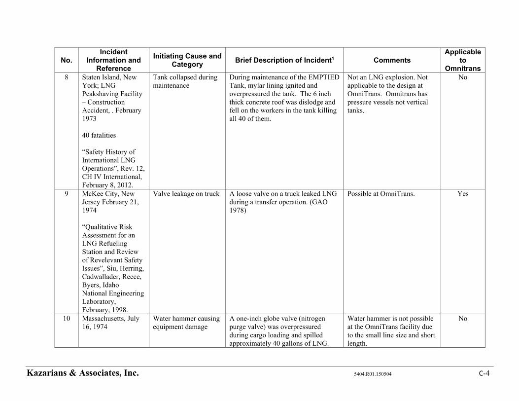
Kazarians & Associates, Inc. 5404.R01.150504 C-4
No. Incident
Information and Reference
Initiating Cause and Category
Brief Description of Incident1 Comments Applicable
to Omnitrans
8 Staten Island, New York; LNG Peakshaving Facility – Construction Accident, . February 1973 40 fatalities “Safety History of International LNG Operations”, Rev. 12, CH IV International, February 8, 2012.
Tank collapsed during maintenance
During maintenance of the EMPTIED Tank, mylar lining ignited and overpressured the tank. The 6 inch thick concrete roof was dislodge and fell on the workers in the tank killing all 40 of them.
Not an LNG explosion. Not applicable to the design at OmniTrans. Omnitrans has pressure vessels not vertical tanks.
No
9 McKee City, New Jersey February 21, 1974 “Qualitative Risk Assessment for an LNG Refueling Station and Review of Revelevant Safety Issues”, Siu, Herring, Cadwallader, Reece, Byers, Idaho National Engineering Laboratory, February, 1998.
Valve leakage on truck A loose valve on a truck leaked LNG during a transfer operation. (GAO 1978)
Possible at OmniTrans. Yes
10 Massachusetts, July 16, 1974
Water hammer causing equipment damage
A one-inch globe valve (nitrogen purge valve) was overpressured during cargo loading and spilled approximately 40 gallons of LNG.
Water hammer is not possible at the OmniTrans facility due to the small line size and short length.
No
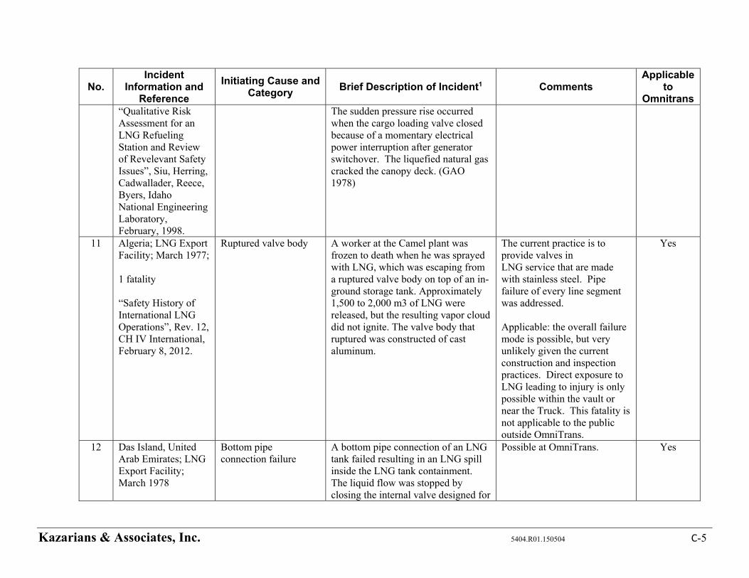
Kazarians & Associates, Inc. 5404.R01.150504 C-5
No. Incident
Information and Reference
Initiating Cause and Category
Brief Description of Incident1 Comments Applicable
to Omnitrans
“Qualitative Risk Assessment for an LNG Refueling Station and Review of Revelevant Safety Issues”, Siu, Herring, Cadwallader, Reece, Byers, Idaho National Engineering Laboratory, February, 1998.
The sudden pressure rise occurred when the cargo loading valve closed because of a momentary electrical power interruption after generator switchover. The liquefied natural gas cracked the canopy deck. (GAO 1978)
11 Algeria; LNG Export Facility; March 1977; 1 fatality “Safety History of International LNG Operations”, Rev. 12, CH IV International, February 8, 2012.
Ruptured valve body A worker at the Camel plant was frozen to death when he was sprayed with LNG, which was escaping from a ruptured valve body on top of an in-ground storage tank. Approximately 1,500 to 2,000 m3 of LNG were released, but the resulting vapor cloud did not ignite. The valve body that ruptured was constructed of cast aluminum.
The current practice is to provide valves in LNG service that are made with stainless steel. Pipe failure of every line segment was addressed. Applicable: the overall failure mode is possible, but very unlikely given the current construction and inspection practices. Direct exposure to LNG leading to injury is only possible within the vault or near the Truck. This fatality is not applicable to the public outside OmniTrans.
Yes
12 Das Island, United Arab Emirates; LNG Export Facility; March 1978
Bottom pipe connection failure
A bottom pipe connection of an LNG tank failed resulting in an LNG spill inside the LNG tank containment. The liquid flow was stopped by closing the internal valve designed for
Possible at OmniTrans. Yes

Kazarians & Associates, Inc. 5404.R01.150504 C-6
No. Incident
Information and Reference
Initiating Cause and Category
Brief Description of Incident1 Comments Applicable
to Omnitrans
No injuries “Safety History of International LNG Operations”, Rev. 12, CH IV International, February 8, 2012.
just such an emergency. A large vapor cloud resulted and dissipated without ignition.
13 Cove Point, Maryland; LNG Import Terminal; October 1979 1 fatality, 1 injury “Safety History of International LNG Operations”, Rev. 12, CH IV International, February 8, 2012.
Explosion due to LNG pump seal leakage into electrical piping
LNG had leaked through an inadequately tightened LNG pump electrical penetration seal, vaporized, passed through 200 feet of underground electrical conduit and entered the substation. Since natural gas was never expected in this substation, no gas detectors had been installed in the building. The natural gas-air mixture was ignited by the normal arcing contacts of a circuit breaker, resulting in an explosion. The explosion killed one operator in the building, seriously injured a second and caused about $3 million in damages. After this incident, building codes pertaining to the equipment and systems downstream of the pump seal were changed.
Addressed. Applicable: The overall failure mode is possible. This fatality is not applicable to the public outside OmniTrans.
Yes
14 Bontang, Indonesia; LNG Export Facility; April 1983
Exchanger rupture due to blind flange left in a flare line during start-up
The main liquefaction column (large vertical, spiral wound, heat exchanger) in Train B ruptured due to overpressurization caused by a blind flange left in a flare line during start-
This was a maintenance error that did not result in a release of LNG. OmniTrans maintenance contractor has proper procedures and
No
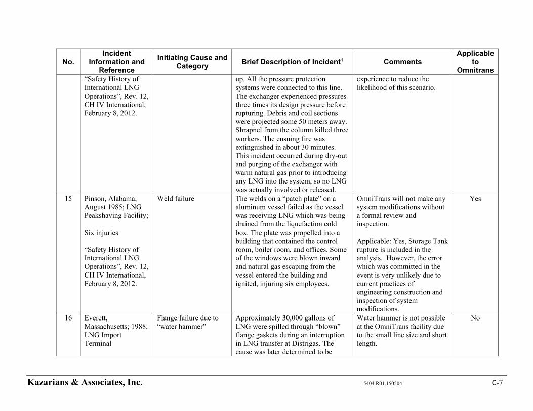
Kazarians & Associates, Inc. 5404.R01.150504 C-7
No. Incident
Information and Reference
Initiating Cause and Category
Brief Description of Incident1 Comments Applicable
to Omnitrans
“Safety History of International LNG Operations”, Rev. 12, CH IV International, February 8, 2012.
up. All the pressure protection systems were connected to this line. The exchanger experienced pressures three times its design pressure before rupturing. Debris and coil sections were projected some 50 meters away. Shrapnel from the column killed three workers. The ensuing fire was extinguished in about 30 minutes. This incident occurred during dry-out and purging of the exchanger with warm natural gas prior to introducing any LNG into the system, so no LNG was actually involved or released.
experience to reduce the likelihood of this scenario.
15 Pinson, Alabama; August 1985; LNG Peakshaving Facility; Six injuries “Safety History of International LNG Operations”, Rev. 12, CH IV International, February 8, 2012.
Weld failure The welds on a “patch plate” on a aluminum vessel failed as the vessel was receiving LNG which was being drained from the liquefaction cold box. The plate was propelled into a building that contained the control room, boiler room, and offices. Some of the windows were blown inward and natural gas escaping from the vessel entered the building and ignited, injuring six employees.
OmniTrans will not make any system modifications without a formal review and inspection. Applicable: Yes, Storage Tank rupture is included in the analysis. However, the error which was committed in the event is very unlikely due to current practices of engineering construction and inspection of system modifications.
Yes
16 Everett, Massachusetts; 1988; LNG Import Terminal
Flange failure due to “water hammer”
Approximately 30,000 gallons of LNG were spilled through “blown” flange gaskets during an interruption in LNG transfer at Distrigas. The cause was later determined to be
Water hammer is not possible at the OmniTrans facility due to the small line size and short length.
No
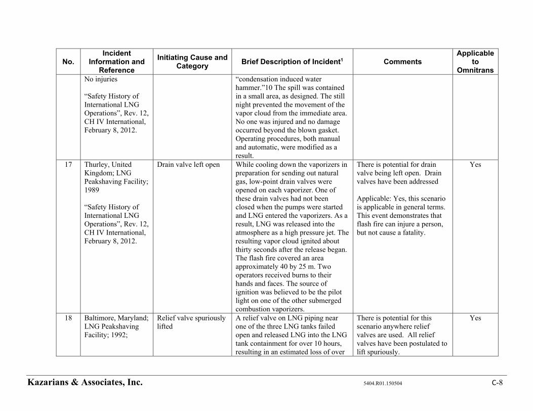
Kazarians & Associates, Inc. 5404.R01.150504 C-8
No. Incident
Information and Reference
Initiating Cause and Category
Brief Description of Incident1 Comments Applicable
to Omnitrans
No injuries “Safety History of International LNG Operations”, Rev. 12, CH IV International, February 8, 2012.
“condensation induced water hammer.”10 The spill was contained in a small area, as designed. The still night prevented the movement of the vapor cloud from the immediate area. No one was injured and no damage occurred beyond the blown gasket. Operating procedures, both manual and automatic, were modified as a result.
17 Thurley, United Kingdom; LNG Peakshaving Facility; 1989 “Safety History of International LNG Operations”, Rev. 12, CH IV International, February 8, 2012.
Drain valve left open While cooling down the vaporizers in preparation for sending out natural gas, low-point drain valves were opened on each vaporizer. One of these drain valves had not been closed when the pumps were started and LNG entered the vaporizers. As a result, LNG was released into the atmosphere as a high pressure jet. The resulting vapor cloud ignited about thirty seconds after the release began. The flash fire covered an area approximately 40 by 25 m. Two operators received burns to their hands and faces. The source of ignition was believed to be the pilot light on one of the other submerged combustion vaporizers.
There is potential for drain valve being left open. Drain valves have been addressed Applicable: Yes, this scenario is applicable in general terms. This event demonstrates that flash fire can injure a person, but not cause a fatality.
Yes
18 Baltimore, Maryland; LNG Peakshaving Facility; 1992;
Relief valve spuriously lifted
A relief valve on LNG piping near one of the three LNG tanks failed open and released LNG into the LNG tank containment for over 10 hours, resulting in an estimated loss of over
There is potential for this scenario anywhere relief valves are used. All relief valves have been postulated to lift spuriously.
Yes
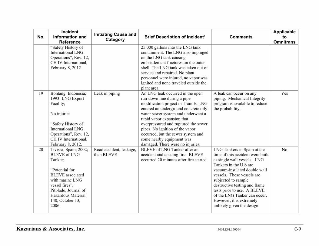
Kazarians & Associates, Inc. 5404.R01.150504 C-9
No. Incident
Information and Reference
Initiating Cause and Category
Brief Description of Incident1 Comments Applicable
to Omnitrans
“Safety History of International LNG Operations”, Rev. 12, CH IV International, February 8, 2012.
25,000 gallons into the LNG tank containment. The LNG also impinged on the LNG tank causing embrittlement fractures on the outer shell. The LNG tank was taken out of service and repaired. No plant personnel were injured, no vapor was ignited and none traveled outside the plant area.
19
Bontang, Indonesia; 1993; LNG Export Facility; No injuries “Safety History of International LNG Operations”, Rev. 12, CH IV International, February 8, 2012.
Leak in piping An LNG leak occurred in the open run-down line during a pipe modification project in Train E. LNG entered an underground concrete oily-water sewer system and underwent a rapid vapor expansion that overpressured and ruptured the sewer pipes. No ignition of the vapor occurred, but the sewer system and some nearby equipment was damaged. There were no injuries.
A leak can occur on any piping. Mechanical Integrity program is available to reduce the probability.
Yes
20 Tivissa, Spain; 2002; BLEVE of LNG Tanker; “Potential for BLEVE associated with marine LNG vessel fires”, Pitblado, Journal of Hazardous Material 140, October 13, 2006.
Road accident, leakage, then BLEVE
BLEVE of LNG Tanker after an accident and ensuing fire. BLEVE occurred 20 minutes after fire started.
LNG Tankers in Spain at the time of this accident were built as single wall vessels. LNG Tankers in the U.S are vacuum-insulated double wall vessels. These vessels are subjected to sample destructive testing and flame tests prior to use. A BLEVE of the LNG Tanker can occur. However, it is extremely unlikely given the design.
No
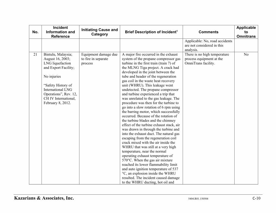
Kazarians & Associates, Inc. 5404.R01.150504 C-10
No. Incident
Information and Reference
Initiating Cause and Category
Brief Description of Incident1 Comments Applicable
to Omnitrans
Applicable: No, road accidents are not considered in this analysis.
21 Bintulu, Malaysia; August 16, 2003; LNG liquefaction and Export Facility; No injuries “Safety History of International LNG Operations”, Rev. 12, CH IV International, February 8, 2012.
Equipment damage due to fire in separate process
A major fire occurred in the exhaust system of the propane compressor gas turbine in the first train (train 7) of the MLNG Tiga project. A crack had developed in the joint between the tube and header of the regeneration gas coil in the waste heat recovery unit (WHRU). This leakage went undetected. The propane compressor and turbine experienced a trip that was unrelated to the gas leakage. The procedure was then for the turbine to go into a slow rotation of 6 rpm using the barring motor, which successfully occurred. Because of the rotation of the turbine blades and the chimney effect of the turbine exhaust stack, air was drawn in through the turbine and into the exhaust duct. The natural gas escaping from the regeneration coil crack mixed with the air inside the WHRU that was still at a very high temperature, near the normal operating exhaust temperature of 570°C. When the gas air mixture reached its lower flammability limit and auto ignition temperature of 537 °C, an explosion inside the WHRU resulted. The incident caused damage to the WHRU ducting, hot oil and
There is no high temperature process equipment at the OmniTrans facility.
No
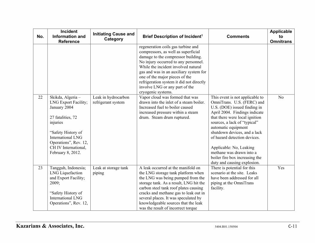
Kazarians & Associates, Inc. 5404.R01.150504 C-11
No. Incident
Information and Reference
Initiating Cause and Category
Brief Description of Incident1 Comments Applicable
to Omnitrans
regeneration coils gas turbine and compressors, as well as superficial damage to the compressor building. No injury occurred to any personnel. While the incident involved natural gas and was in an auxiliary system for one of the major pieces of the refrigeration system it did not directly involve LNG or any part of the cryogenic systems.
22 Skikda, Algeria – LNG Export Facility; January 2004 27 fatalities, 72 injuries “Safety History of International LNG Operations”, Rev. 12, CH IV International, February 8, 2012.
Leak in hydrocarbon refrigerant system
Vapor cloud was formed that was drawn into the inlet of a steam boiler. Increased fuel to boiler caused increased pressure within a steam drum. Steam drum ruptured.
This event is not applicable to OmniTrans. U.S. (FERC) and U.S. (DOE) issued finding in April 2004. Findings indicate that there were local ignition sources, a lack of “typical” automatic equipment shutdown devices, and a lack of hazard detection devices. Applicable: No, Leaking methane was drawn into a boiler fire box increasing the duty and causing explosion.
No
23 Tangguh, Indonesia; LNG Liquefaction and Export Facility; 2009; “Safety History of International LNG Operations”, Rev. 12,
Leak at storage tank piping
A leak occurred at the manifold on the LNG storage tank platform when the LNG was being pumped from the storage tank. As a result, LNG hit the carbon steel tank roof plates causing cracks and methane gas to leak out in several places. It was speculated by knowledgeable sources that the leak was the result of incorrect torque
There is potential for this scenario at the site. Leaks have been addressed for all piping at the OmniTrans facility.
Yes
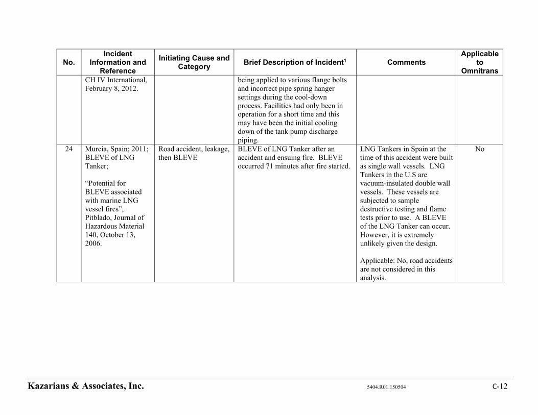
Kazarians & Associates, Inc. 5404.R01.150504 C-12
No. Incident
Information and Reference
Initiating Cause and Category
Brief Description of Incident1 Comments Applicable
to Omnitrans
CH IV International, February 8, 2012.
being applied to various flange bolts and incorrect pipe spring hanger settings during the cool-down process. Facilities had only been in operation for a short time and this may have been the initial cooling down of the tank pump discharge piping.
24 Murcia, Spain; 2011; BLEVE of LNG Tanker; “Potential for BLEVE associated with marine LNG vessel fires”, Pitblado, Journal of Hazardous Material 140, October 13, 2006.
Road accident, leakage, then BLEVE
BLEVE of LNG Tanker after an accident and ensuing fire. BLEVE occurred 71 minutes after fire started.
LNG Tankers in Spain at the time of this accident were built as single wall vessels. LNG Tankers in the U.S are vacuum-insulated double wall vessels. These vessels are subjected to sample destructive testing and flame tests prior to use. A BLEVE of the LNG Tanker can occur. However, it is extremely unlikely given the design. Applicable: No, road accidents are not considered in this analysis.
No

Appendix D – HAZOP Worksheets
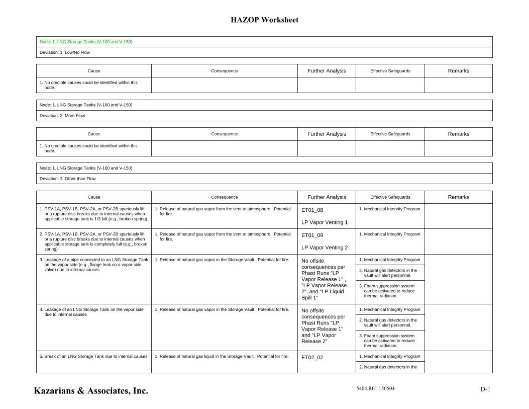
Node: 1. LNG Storage Tanks (V-100 and V-150)
Deviation: 1. Low/No Flow
Cause Consequence Further Analysis Effective Safeguards Remarks
1. No credible causes could be identified within this node.
Node: 1. LNG Storage Tanks (V-100 and V-150)
Deviation: 2. More Flow
Cause Consequence Further Analysis Effective Safeguards Remarks
1. No credible causes could be identified within this node.
Node: 1. LNG Storage Tanks (V-100 and V-150)
Deviation: 3. Other than Flow
Cause Consequence Further Analysis Effective Safeguards Remarks
1. Mechanical Integrity Program1. Release of natural gas vapor from the vent to atmosphere. Potential for fire.
ET01_08
LP Vapor Venting 1
1. PSV-1A, PSV-1B, PSV-2A, or PSV-2B spuriously lift or a rupture disc breaks due to internal causes when applicable storage tank is 1/3 full (e.g., broken spring)
1. Mechanical Integrity Program1. Release of natural gas vapor from the vent to atmosphere. Potential for fire.
ET01_09
LP Vapor Venting 2
2. PSV-1A, PSV-1B, PSV-2A, or PSV-2B spuriously lift or a rupture disc breaks due to internal causes when applicable storage tank is completely full (e.g., broken spring)
1. Mechanical Integrity Program
2. Natural gas detectors in the vault will alert personnel.
3. Foam suppression system can be activated to reduce thermal radiation.
1. Release of natural gas vapor in the Storage Vault. Potential for fire. No offsite consequences per Phast Runs "LP Vapor Release 1" , "LP Vapor Release 2", and "LP Liquid Spill 1"
3. Leakage of a pipe connected to an LNG Storage Tank on the vapor side (e.g., flange leak on a vapor side valve) due to internal causes
1. Mechanical Integrity Program
2. Natural gas detectors in the vault will alert personnel.
3. Foam suppression system can be activated to reduce thermal radiation.
1. Release of natural gas vapor in the Storage Vault. Potential for fire. No offsite consequences per Phast Runs "LP Vapor Release 1" and "LP Vapor Release 2"
4. Leakage of an LNG Storage Tank on the vapor side due to internal causes
1. Mechanical Integrity Program
2. Natural gas detectors in the
1. Release of natural gas liquid in the Storage Vault. Potential for fire. ET02_025. Break of an LNG Storage Tank due to internal causes
HAZOP Worksheet
Kazarians & Associates, Inc. 5404.R01.150504 D-1
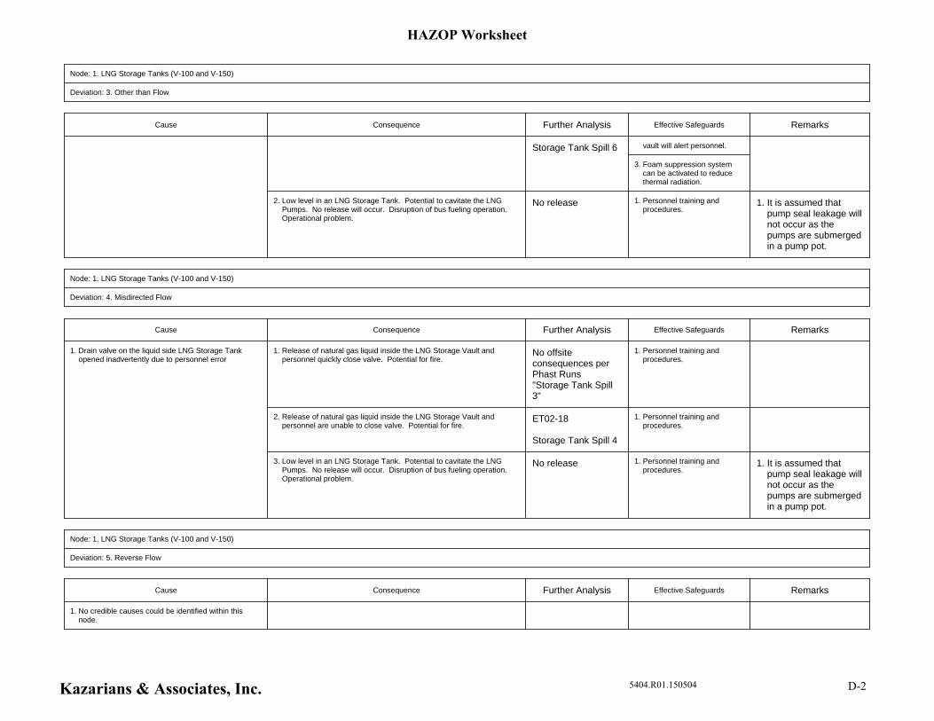
Node: 1. LNG Storage Tanks (V-100 and V-150)
Deviation: 3. Other than Flow
Cause Consequence Further Analysis Effective Safeguards Remarks
vault will alert personnel.
3. Foam suppression system can be activated to reduce thermal radiation.
Storage Tank Spill 6
1. Personnel training and procedures.
1. It is assumed that pump seal leakage will not occur as the pumps are submerged in a pump pot.
2. Low level in an LNG Storage Tank. Potential to cavitate the LNG Pumps. No release will occur. Disruption of bus fueling operation. Operational problem.
No release
Node: 1. LNG Storage Tanks (V-100 and V-150)
Deviation: 4. Misdirected Flow
Cause Consequence Further Analysis Effective Safeguards Remarks
1. Personnel training and procedures.
1. Release of natural gas liquid inside the LNG Storage Vault and personnel quickly close valve. Potential for fire.
No offsite consequences per Phast Runs "Storage Tank Spill 3"
1. Personnel training and procedures.
2. Release of natural gas liquid inside the LNG Storage Vault and personnel are unable to close valve. Potential for fire.
ET02-18
Storage Tank Spill 4
1. Personnel training and procedures.
1. It is assumed that pump seal leakage will not occur as the pumps are submerged in a pump pot.
3. Low level in an LNG Storage Tank. Potential to cavitate the LNG Pumps. No release will occur. Disruption of bus fueling operation. Operational problem.
No release
1. Drain valve on the liquid side LNG Storage Tank opened inadvertently due to personnel error
Node: 1. LNG Storage Tanks (V-100 and V-150)
Deviation: 5. Reverse Flow
Cause Consequence Further Analysis Effective Safeguards Remarks
1. No credible causes could be identified within this node.
HAZOP Worksheet
Kazarians & Associates, Inc. 5404.R01.150504 D-2
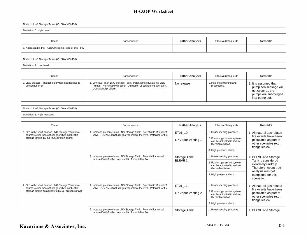
Node: 1. LNG Storage Tanks (V-100 and V-150)
Deviation: 6. High Level
Cause Consequence Further Analysis Effective Safeguards Remarks
1. Addressed in the Truck Offloading Node of this PHA.
Node: 1. LNG Storage Tanks (V-100 and V-150)
Deviation: 7. Low Level
Cause Consequence Further Analysis Effective Safeguards Remarks
1. Personnel training and procedures.
1. It is assumed that pump seal leakage will not occur as the pumps are submerged in a pump pot.
1. Low level in an LNG Storage Tank. Potential to cavitate the LNG Pumps. No release will occur. Disruption of bus fueling operation. Operational problem.
No release1. LNG Storage Tank not filled when needed due to personnel error
Node: 1. LNG Storage Tanks (V-100 and V-150)
Deviation: 8. High Pressure
Cause Consequence Further Analysis Effective Safeguards Remarks
1. Housekeeping practices.
2. Foam suppression system can be activated to reduce thermal radiation.
3. High pressure alarm.
1. All natural gas related fire events have been postulated as part of other scenarios (e.g., flange leaks).
1. Increase pressure in an LNG Storage Tank. Potential to lift a relief valve. Release of natural gas vapor from the vent. Potential for fire.
ET01_10
LP Vapor Venting 1
1. Housekeeping practices.
2. Foam suppression system can be activated to reduce thermal radiation.
3. High pressure alarm.
1. BLEVE of a Storage Tank is considered extremely unlikely. Therefore, event tree analysis was not completed for this scenario.
2. Increase pressure in an LNG Storage Tank. Potential for vessel rupture if relief valve does not lift. Potential for fire.
Storage Tank BLEVE 1
1. Fire in the vault near an LNG Storage Tank from sources other than natural gas when applicable storage tank is 1/3 full (e.g., broken spring)
1. Housekeeping practices.
2. Foam suppression system can be activated to reduce thermal radiation.
3. High pressure alarm.
1. All natural gas related fire events have been postulated as part of other scenarios (e.g., flange leaks).
1. Increase pressure in an LNG Storage Tank. Potential to lift a relief valve. Release of natural gas vapor from the vent. Potential for fire.
ET01_11
LP Vapor Venting 2
1. Housekeeping practices. 1. BLEVE of a Storage 2. Increase pressure in an LNG Storage Tank. Potential for vessel rupture if relief valve does not lift. Potential for fire.
Storage Tank
2. Fire in the vault near an LNG Storage Tank from sources other than natural gas when applicable storage tank is completely full (e.g., broken spring)
HAZOP Worksheet
Kazarians & Associates, Inc. 5404.R01.150504 D-3
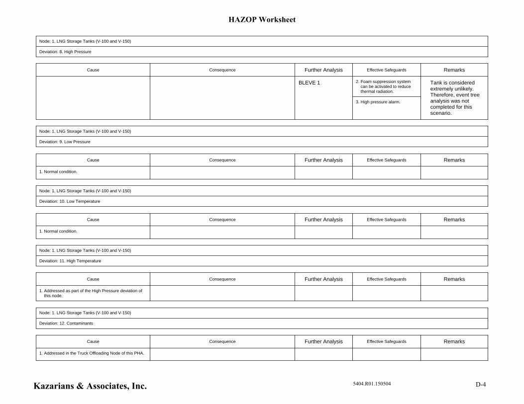
Node: 1. LNG Storage Tanks (V-100 and V-150)
Deviation: 8. High Pressure
Cause Consequence Further Analysis Effective Safeguards Remarks
2. Foam suppression system can be activated to reduce thermal radiation.
3. High pressure alarm.
Tank is considered extremely unlikely. Therefore, event tree analysis was not completed for this scenario.
BLEVE 1
Node: 1. LNG Storage Tanks (V-100 and V-150)
Deviation: 9. Low Pressure
Cause Consequence Further Analysis Effective Safeguards Remarks
1. Normal condition.
Node: 1. LNG Storage Tanks (V-100 and V-150)
Deviation: 10. Low Temperature
Cause Consequence Further Analysis Effective Safeguards Remarks
1. Normal condition.
Node: 1. LNG Storage Tanks (V-100 and V-150)
Deviation: 11. High Temperature
Cause Consequence Further Analysis Effective Safeguards Remarks
1. Addressed as part of the High Pressure deviation of this node.
Node: 1. LNG Storage Tanks (V-100 and V-150)
Deviation: 12. Contaminants
Cause Consequence Further Analysis Effective Safeguards Remarks
1. Addressed in the Truck Offloading Node of this PHA.
HAZOP Worksheet
Kazarians & Associates, Inc. 5404.R01.150504 D-4
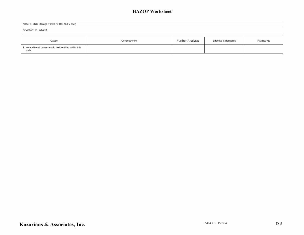
Node: 1. LNG Storage Tanks (V-100 and V-150)
Deviation: 13. What-If
Cause Consequence Further Analysis Effective Safeguards Remarks
1. No additional causes could be identified within this node.
HAZOP Worksheet
Kazarians & Associates, Inc. 5404.R01.150504 D-5
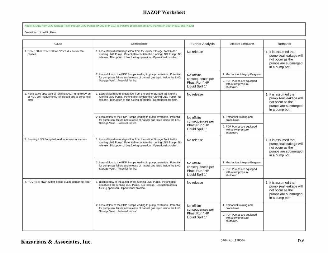
Node: 2. LNG from LNG Storage Tank through LNG Pumps (P-200 or P-210) to Positive Displacement LNG Pumps (P-300, P-310, and P-320)
Deviation: 1. Low/No Flow
Cause Consequence Further Analysis Effective Safeguards Remarks
1. It is assumed that pump seal leakage will not occur as the pumps are submerged in a pump pot.
1. Loss of liquid natural gas flow from the online Storage Tank to the running LNG Pump. Potential to cavitate the running LNG Pump. No release. Disruption of bus fueling operation. Operational problem.
No release
1. Mechanical Integrity Program
2. PDP Pumps are equipped with a low pressure shutdown.
2. Loss of flow to the PDP Pumps leading to pump cavitation. Potential for pump seal failure and release of natural gas liquid inside the LNG Storage Vault. Potential for fire.
No offsite consequences per Phast Run "HP Liquid Spill 1"
1. ROV-100 or ROV-150 fail closed due to internal causes
1. It is assumed that pump seal leakage will not occur as the pumps are submerged in a pump pot.
1. Loss of liquid natural gas flow from the online Storage Tank to the running LNG Pump. Potential to cavitate the running LNG Pump. No release. Disruption of bus fueling operation. Operational problem.
No release
1. Personnel training and procedures.
2. PDP Pumps are equipped with a low pressure shutdown.
2. Loss of flow to the PDP Pumps leading to pump cavitation. Potential for pump seal failure and release of natural gas liquid inside the LNG Storage Vault. Potential for fire.
No offsite consequences per Phast Run "HP Liquid Spill 1"
2. Hand valve upstream of running LNG Pump (HCV-25 or HCV-24) inadvertently left closed due to personnel error
1. It is assumed that pump seal leakage will not occur as the pumps are submerged in a pump pot.
1. Loss of liquid natural gas flow from the online Storage Tank to the running LNG Pump. Potential to cavitate the running LNG Pump. No release. Disruption of bus fueling operation. Operational problem.
No release
1. Mechanical Integrity Program
2. PDP Pumps are equipped with a low pressure shutdown.
2. Loss of flow to the PDP Pumps leading to pump cavitation. Potential for pump seal failure and release of natural gas liquid inside the LNG Storage Vault. Potential for fire.
No offsite consequences per Phast Run "HP Liquid Spill 1"
3. Running LNG Pump failure due to internal causes
1. It is assumed that pump seal leakage will not occur as the pumps are submerged in a pump pot.
1. Blocked flow at the outlet of the running LNG Pump. Potential to deadhead the running LNG Pump. No release. Disruption of bus fueling operation. Operational problem.
No release
1. Personnel training and procedures.
2. PDP Pumps are equipped with a low pressure shutdown.
2. Loss of flow to the PDP Pumps leading to pump cavitation. Potential for pump seal failure and release of natural gas liquid inside the LNG Storage Vault. Potential for fire.
No offsite consequences per Phast Run "HP Liquid Spill 1"
4. HCV-42 or HCV-43 left closed due to personnel error
HAZOP Worksheet
Kazarians & Associates, Inc. 5404.R01.150504 D-6
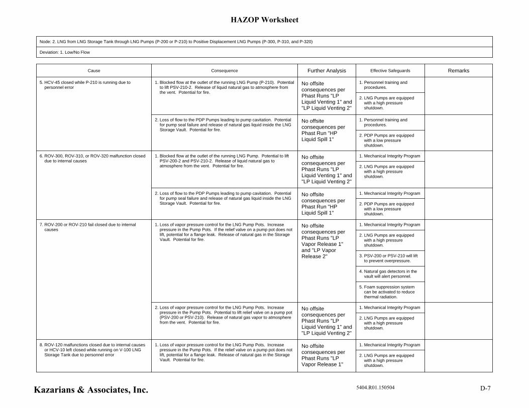
Node: 2. LNG from LNG Storage Tank through LNG Pumps (P-200 or P-210) to Positive Displacement LNG Pumps (P-300, P-310, and P-320)
Deviation: 1. Low/No Flow
Cause Consequence Further Analysis Effective Safeguards Remarks
1. Personnel training and procedures.
2. LNG Pumps are equipped with a high pressure shutdown.
1. Blocked flow at the outlet of the running LNG Pump (P-210). Potential to lift PSV-210-2. Release of liquid natural gas to atmosphere from the vent. Potential for fire.
No offsite consequences per Phast Runs "LP Liquid Venting 1" and "LP Liquid Venting 2"
1. Personnel training and procedures.
2. PDP Pumps are equipped with a low pressure shutdown.
2. Loss of flow to the PDP Pumps leading to pump cavitation. Potential for pump seal failure and release of natural gas liquid inside the LNG Storage Vault. Potential for fire.
No offsite consequences per Phast Run "HP Liquid Spill 1"
5. HCV-45 closed while P-210 is running due to personnel error
1. Mechanical Integrity Program
2. LNG Pumps are equipped with a high pressure shutdown.
1. Blocked flow at the outlet of the running LNG Pump. Potential to lift PSV-200-2 and PSV-210-2. Release of liquid natural gas to atmosphere from the vent. Potential for fire.
No offsite consequences per Phast Runs "LP Liquid Venting 1" and "LP Liquid Venting 2"
1. Mechanical Integrity Program
2. PDP Pumps are equipped with a low pressure shutdown.
2. Loss of flow to the PDP Pumps leading to pump cavitation. Potential for pump seal failure and release of natural gas liquid inside the LNG Storage Vault. Potential for fire.
No offsite consequences per Phast Run "HP Liquid Spill 1"
6. ROV-300, ROV-310, or ROV-320 malfunction closed due to internal causes
1. Mechanical Integrity Program
2. LNG Pumps are equipped with a high pressure shutdown.
3. PSV-200 or PSV-210 will lift to prevent overpressure.
4. Natural gas detectors in the vault will alert personnel.
5. Foam suppression system can be activated to reduce thermal radiation.
1. Loss of vapor pressure control for the LNG Pump Pots. Increase pressure in the Pump Pots. If the relief valve on a pump pot does not lift, potential for a flange leak. Release of natural gas in the Storage Vault. Potential for fire.
No offsite consequences per Phast Runs "LP Vapor Release 1" and "LP Vapor Release 2"
1. Mechanical Integrity Program
2. LNG Pumps are equipped with a high pressure shutdown.
2. Loss of vapor pressure control for the LNG Pump Pots. Increase pressure in the Pump Pots. Potential to lift relief valve on a pump pot (PSV-200 or PSV-210). Release of natural gas vapor to atmosphere from the vent. Potential for fire.
No offsite consequences per Phast Runs "LP Liquid Venting 1" and "LP Liquid Venting 2"
7. ROV-200 or ROV-210 fail closed due to internal causes
1. Mechanical Integrity Program
2. LNG Pumps are equipped with a high pressure shutdown.
1. Loss of vapor pressure control for the LNG Pump Pots. Increase pressure in the Pump Pots. If the relief valve on a pump pot does not lift, potential for a flange leak. Release of natural gas in the Storage Vault. Potential for fire.
No offsite consequences per Phast Runs "LP Vapor Release 1"
8. ROV-120 malfunctions closed due to internal causes or HCV-10 left closed while running on V-100 LNG Storage Tank due to personnel error
HAZOP Worksheet
Kazarians & Associates, Inc. 5404.R01.150504 D-7

Node: 2. LNG from LNG Storage Tank through LNG Pumps (P-200 or P-210) to Positive Displacement LNG Pumps (P-300, P-310, and P-320)
Deviation: 1. Low/No Flow
Cause Consequence Further Analysis Effective Safeguards Remarks
3. PSV-120, PSV-200 or PSV-210 will lift to prevent overpressure.
4. Natural gas detectors in the vault will alert personnel.
5. Foam suppression system can be activated to reduce thermal radiation.
and "LP Vapor Release 2"
1. Mechanical Integrity Program
2. LNG Pumps are equipped with a high pressure shutdown.
2. Loss of vapor pressure control for the LNG Pump Pots. Increase pressure in the Pump Pots. Potential to lift relief valve on a pump pot (PSV-200 PSV-120, or PSV-210). Release of natural gas to atmosphere from the vent. Potential for fire.
No offsite consequences per Phast Runs "LP Liquid Venting 1" and "LP Liquid Venting 2"
1. Mechanical Integrity Program
2. LNG Pumps are equipped with a high pressure shutdown.
3. PSV-200 or PSV-210 will lift to prevent overpressure.
4. Natural gas detectors in the vault will alert personnel.
5. Foam suppression system can be activated to reduce thermal radiation.
1. Loss of vapor pressure control for the LNG Pump Pots. Increase pressure in the Pump Pots. If the relief valve on a pump pot does not lift, potential for a flange leak. Release of natural gas in the Storage Vault. Potential for fire.
No offsite consequences per Phast Runs "LP Vapor Release 1" and "LP Vapor Release 2"
1. Mechanical Integrity Program
2. LNG Pumps are equipped with a high pressure shutdown.
2. Loss of vapor pressure control for the LNG Pump Pots. Increase pressure in the Pump Pots. Potential to lift relief valve on a pump pot (PSV-200 or PSV-210). Release of natural gas to atmosphere from the vent. Potential for fire.
No offsite consequences per Phast Runs "LP Liquid Venting 1" and "LP Liquid Venting 2"
9. ROV-170 malfunctions closed while running on V-150 LNG Storage Tank due to internal causes
1. Mechanical Integrity Program
2. LNG Pumps are equipped with a high pressure shutdown.
3. PSV-170, PSV-200, or PSV-210 will lift to prevent overpressure.
4. Natural gas detectors in the vault will alert personnel.
5. Foam suppression system
1. Loss of vapor pressure control for the LNG Pump Pots. Increase pressure in the Pump Pots. If the relief valve on a pump pot does not lift, potential for a flange leak. Release of natural gas in the Storage Vault. Potential for fire.
No offsite consequences per Phast Runs "LP Vapor Release 1" and "LP Vapor Release 2"
10. HCV-10-1 left closed while running on V-150 LNG Storage Tank due to personnel error
HAZOP Worksheet
Kazarians & Associates, Inc. 5404.R01.150504 D-8
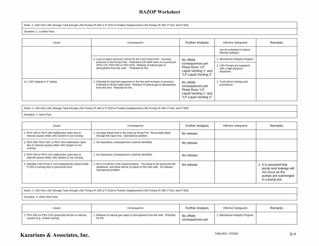
Node: 2. LNG from LNG Storage Tank through LNG Pumps (P-200 or P-210) to Positive Displacement LNG Pumps (P-300, P-310, and P-320)
Deviation: 1. Low/No Flow
Cause Consequence Further Analysis Effective Safeguards Remarks
can be activated to reduce thermal radiation.
1. Mechanical Integrity Program
2. LNG Pumps are equipped with a high pressure shutdown.
2. Loss of vapor pressure control for the LNG Pump Pots. Increase pressure in the Pump Pots. Potential to lift relief valve on a pump pot (PSV-170, PSV-200 or PSV-210). Release of natural gas to atmosphere from the vent. Potential for fire.
No offsite consequences per Phast Runs "LP Liquid Venting 1" and "LP Liquid Venting 2"
1. Truck driver training and procedures.
1. Potential for thermal expansion in the line and increase in pressure. Potential to lift the relief valve. Release of natural gas to atmosphere from the vent. Potential for fire.
No offsite consequences per Phast Runs "LP Liquid Venting 1" and "LP Liquid Venting 2"
11. LNG trapped in 3" piping
Node: 2. LNG from LNG Storage Tank through LNG Pumps (P-200 or P-210) to Positive Displacement LNG Pumps (P-300, P-310, and P-320)
Deviation: 2. More Flow
Cause Consequence Further Analysis Effective Safeguards Remarks
1. Increase liquid level in the lined up Pump Pot. Recirculate liquid through the vapor line. Operational problem.
No release1. ROV-100 or ROV-150 malfunction open due to internal causes while LNG System is not running
1. No hazardous consequences could be identified. No release2. ROV-300, ROV-310, or ROV-320 malfunction open due to internal causes while LNG System is not running
1. No hazardous consequences could be identified. No release3. ROV-200 or ROV-210 malfunction open due to internal causes while LNG System is not running
1. It is assumed that pump seal leakage will not occur as the pumps are submerged in a pump pot.
1. HCV-24 will be in the closed position. The liquid in the pump pot will deadhead, and there will be no liquid on the inlet side. No release. Operational problem.
No release4. Standby LNG Pump P-210 inadvertently started while P-200 is running due to personnel error
Node: 2. LNG from LNG Storage Tank through LNG Pumps (P-200 or P-210) to Positive Displacement LNG Pumps (P-300, P-310, and P-320)
Deviation: 3. Other than Flow
Cause Consequence Further Analysis Effective Safeguards Remarks
1. Mechanical Integrity Program1. Release of natural gas vapor to atmosphere from the vent. Potential for fire.
No offsite consequences per
1. PSV-200 (or PSV-210) spuriously lift due to internal causes (e.g., broken spring)
HAZOP Worksheet
Kazarians & Associates, Inc. 5404.R01.150504 D-9

Node: 2. LNG from LNG Storage Tank through LNG Pumps (P-200 or P-210) to Positive Displacement LNG Pumps (P-300, P-310, and P-320)
Deviation: 3. Other than Flow
Cause Consequence Further Analysis Effective Safeguards Remarks
Phast Run "LP Vapor Venting 3"
1. Mechanical Integrity Program1. Release of natural gas vapor to atmosphere from the vent. Potential for fire.
No offsite consequences per Phast Run "Storage Tank Spill 2"
2. PSV-140 spuriously lifts due to internal causes (e.g., broken spring)
1. Mechanical Integrity Program1. Release of natural gas vapor to atmosphere from the vent. Potential for fire.
No offsite consequences per Phast Run "Storage Tank Spill 2"
3. PSV-120, PSV-160, or PSV-170 spuriously lift due to internal causes (e.g., broken spring)
1. Mechanical Integrity Program 1. Item in parentheses refers to standby equipment.
1. Release of natural gas vapor to atmosphere from the vent. Potential for fire.
No offsite consequences per Phast Run "Storage Tank Spill 2"
4. PSV-200-2 (or PSV-210-2) spuriously lift due to internal causes (e.g., broken spring)
1. Mechanical Integrity Program
2. Natural gas detectors in the vault will alert personnel.
3. Foam suppression system can be activated to reduce thermal radiation.
1. Release of natural gas liquid in the Storage Vault. Potential for fire. No offsite consequences per Phast Runs "LP Vapor Release 1" and "LP Vapor Release 2"
5. Pump Pot flange leak due to internal causes or tightening error
1. Mechanical Integrity Program
2. Natural gas detectors in the vault will alert personnel.
3. Foam suppression system can be activated to reduce thermal radiation.
1. Release of natural gas vapor in the Storage Vault. Potential for fire. No offsite consequences per Phast Runs "LP Vapor Release 1", "LP Vapor Release 2", "LP Liquid Spill 5"
6. Leakage of a pipe on the vapor side (e.g., flange leak on a vapor side valve) due to internal causes
1. Mechanical Integrity Program
2. Natural gas detectors in the vault will alert personnel.
3. Foam suppression system can be activated to reduce thermal radiation.
1. Release of natural gas liquid in the Storage Vault. Potential for fire. ET02_01
Storage Tank Spill 1
7. Leakage of a pipe connected to an LNG Storage Tank on the liquid side (e.g., 3" pipe break) due to internal causes
1. Mechanical Integrity Program
2. *LNG Pumps are equipped with a low pressure shudown.
3. Natural gas detectors in the vault will alert personnel.
1. Release of natural gas liquid in the Storage Vault. Potential for fire. ET02_03
LP Liquid Spill 6 (1/2" pipe
8. Leakage of a pipe on the liquid side (1/2" pipe break downstream of LNG Pumps) due to internal causes
HAZOP Worksheet
Kazarians & Associates, Inc. 5404.R01.150504 D-10
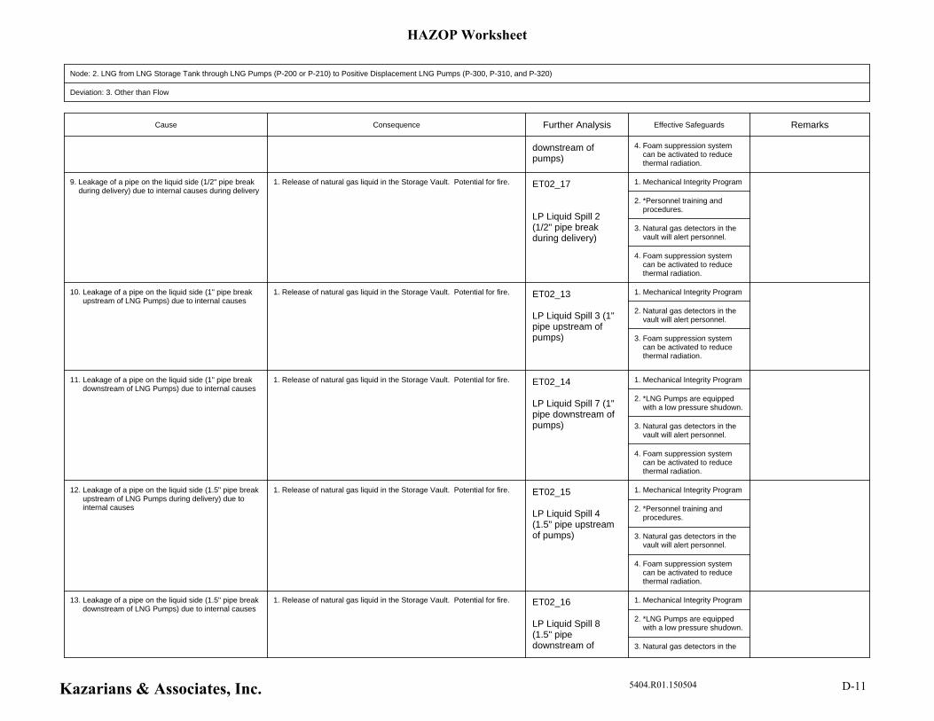
Node: 2. LNG from LNG Storage Tank through LNG Pumps (P-200 or P-210) to Positive Displacement LNG Pumps (P-300, P-310, and P-320)
Deviation: 3. Other than Flow
Cause Consequence Further Analysis Effective Safeguards Remarks
4. Foam suppression system can be activated to reduce thermal radiation.
downstream of pumps)
1. Mechanical Integrity Program
2. *Personnel training and procedures.
3. Natural gas detectors in the vault will alert personnel.
4. Foam suppression system can be activated to reduce thermal radiation.
1. Release of natural gas liquid in the Storage Vault. Potential for fire. ET02_17
LP Liquid Spill 2 (1/2" pipe break during delivery)
9. Leakage of a pipe on the liquid side (1/2" pipe break during delivery) due to internal causes during delivery
1. Mechanical Integrity Program
2. Natural gas detectors in the vault will alert personnel.
3. Foam suppression system can be activated to reduce thermal radiation.
1. Release of natural gas liquid in the Storage Vault. Potential for fire. ET02_13
LP Liquid Spill 3 (1" pipe upstream of pumps)
10. Leakage of a pipe on the liquid side (1" pipe break upstream of LNG Pumps) due to internal causes
1. Mechanical Integrity Program
2. *LNG Pumps are equipped with a low pressure shudown.
3. Natural gas detectors in the vault will alert personnel.
4. Foam suppression system can be activated to reduce thermal radiation.
1. Release of natural gas liquid in the Storage Vault. Potential for fire. ET02_14
LP Liquid Spill 7 (1" pipe downstream of pumps)
11. Leakage of a pipe on the liquid side (1" pipe break downstream of LNG Pumps) due to internal causes
1. Mechanical Integrity Program
2. *Personnel training and procedures.
3. Natural gas detectors in the vault will alert personnel.
4. Foam suppression system can be activated to reduce thermal radiation.
1. Release of natural gas liquid in the Storage Vault. Potential for fire. ET02_15
LP Liquid Spill 4 (1.5" pipe upstream of pumps)
12. Leakage of a pipe on the liquid side (1.5" pipe break upstream of LNG Pumps during delivery) due to internal causes
1. Mechanical Integrity Program
2. *LNG Pumps are equipped with a low pressure shudown.
3. Natural gas detectors in the
1. Release of natural gas liquid in the Storage Vault. Potential for fire. ET02_16
LP Liquid Spill 8 (1.5" pipe downstream of
13. Leakage of a pipe on the liquid side (1.5" pipe break downstream of LNG Pumps) due to internal causes
HAZOP Worksheet
Kazarians & Associates, Inc. 5404.R01.150504 D-11
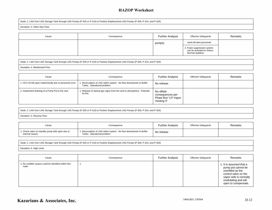
Node: 2. LNG from LNG Storage Tank through LNG Pumps (P-200 or P-210) to Positive Displacement LNG Pumps (P-300, P-310, and P-320)
Deviation: 3. Other than Flow
Cause Consequence Further Analysis Effective Safeguards Remarks
vault will alert personnel.
4. Foam suppression system can be activated to reduce thermal radiation.
pumps)
Node: 2. LNG from LNG Storage Tank through LNG Pumps (P-200 or P-210) to Positive Displacement LNG Pumps (P-300, P-310, and P-320)
Deviation: 4. Misdirected Flow
Cause Consequence Further Analysis Effective Safeguards Remarks
1. Recirculation of LNG within system. No flow downstream to Buffer Tanks. Operational problem.
No release1. HCV-44 left open inadvertently due to personnel error
1. Release of natural gas vapor from the vent to atmosphere. Potential for fire.
No offsite consequences per Phast Run "LP Vapor Venting 4"
2. Inadvertent draining of a Pump Pot to the vent
Node: 2. LNG from LNG Storage Tank through LNG Pumps (P-200 or P-210) to Positive Displacement LNG Pumps (P-300, P-310, and P-320)
Deviation: 5. Reverse Flow
Cause Consequence Further Analysis Effective Safeguards Remarks
1. Recirculation of LNG within system. No flow downstream to Buffer Tanks. Operational problem.
No release1. Check valve on standby pump fails open due to internal causes
Node: 2. LNG from LNG Storage Tank through LNG Pumps (P-200 or P-210) to Positive Displacement LNG Pumps (P-300, P-310, and P-320)
Deviation: 6. High Level
Cause Consequence Further Analysis Effective Safeguards Remarks
1. It is assumed that a pump pot cannot be overfilled as the control valve on the vapor side is normally modulating and will open to compensate.
1. 1. No credible causes could be identified within this node.
HAZOP Worksheet
Kazarians & Associates, Inc. 5404.R01.150504 D-12
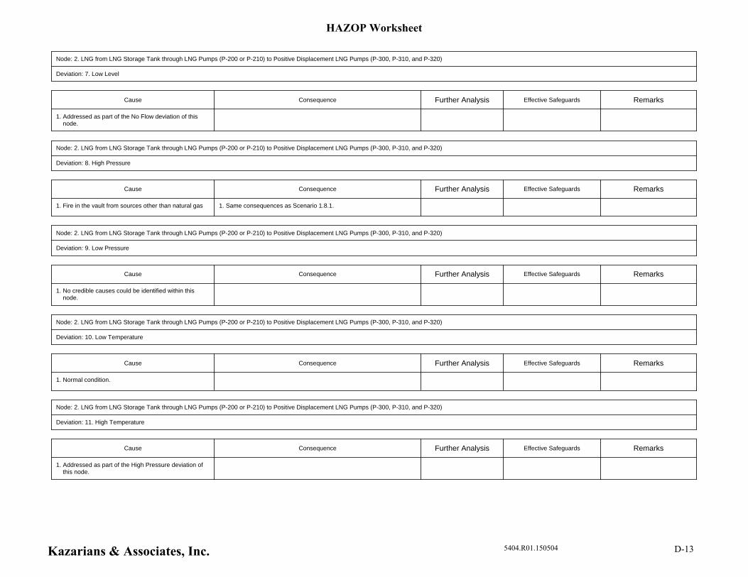
Node: 2. LNG from LNG Storage Tank through LNG Pumps (P-200 or P-210) to Positive Displacement LNG Pumps (P-300, P-310, and P-320)
Deviation: 7. Low Level
Cause Consequence Further Analysis Effective Safeguards Remarks
1. Addressed as part of the No Flow deviation of this node.
Node: 2. LNG from LNG Storage Tank through LNG Pumps (P-200 or P-210) to Positive Displacement LNG Pumps (P-300, P-310, and P-320)
Deviation: 8. High Pressure
Cause Consequence Further Analysis Effective Safeguards Remarks
1. Same consequences as Scenario 1.8.1.1. Fire in the vault from sources other than natural gas
Node: 2. LNG from LNG Storage Tank through LNG Pumps (P-200 or P-210) to Positive Displacement LNG Pumps (P-300, P-310, and P-320)
Deviation: 9. Low Pressure
Cause Consequence Further Analysis Effective Safeguards Remarks
1. No credible causes could be identified within this node.
Node: 2. LNG from LNG Storage Tank through LNG Pumps (P-200 or P-210) to Positive Displacement LNG Pumps (P-300, P-310, and P-320)
Deviation: 10. Low Temperature
Cause Consequence Further Analysis Effective Safeguards Remarks
1. Normal condition.
Node: 2. LNG from LNG Storage Tank through LNG Pumps (P-200 or P-210) to Positive Displacement LNG Pumps (P-300, P-310, and P-320)
Deviation: 11. High Temperature
Cause Consequence Further Analysis Effective Safeguards Remarks
1. Addressed as part of the High Pressure deviation of this node.
HAZOP Worksheet
Kazarians & Associates, Inc. 5404.R01.150504 D-13
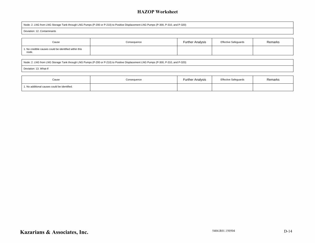
Node: 2. LNG from LNG Storage Tank through LNG Pumps (P-200 or P-210) to Positive Displacement LNG Pumps (P-300, P-310, and P-320)
Deviation: 12. Contaminants
Cause Consequence Further Analysis Effective Safeguards Remarks
1. No credible causes could be identified within this node.
Node: 2. LNG from LNG Storage Tank through LNG Pumps (P-200 or P-210) to Positive Displacement LNG Pumps (P-300, P-310, and P-320)
Deviation: 13. What-If
Cause Consequence Further Analysis Effective Safeguards Remarks
1. No additional causes could be identified.
HAZOP Worksheet
Kazarians & Associates, Inc. 5404.R01.150504 D-14
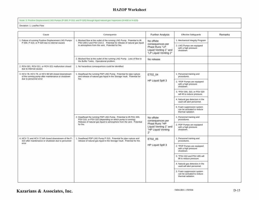
Node: 3. Positive Displacement LNG Pumps (P-300, P-310, and P-320) through liquid natural gas Vaporizers (H-400 or H-410)
Deviation: 1. Low/No Flow
Cause Consequence Further Analysis Effective Safeguards Remarks
1. Mechanical Integrity Program
2. LNG Pumps are equipped with a high pressure shutdown.
1. Blocked flow at the outlet of the running LNG Pump. Potential to lift PSV-200-2 and PSV-210-2. Potential for release of natural gas liquid to atmosphere from the vent. Potential for fire.
No offsite consequences per Phast Runs "LP Liquid Venting 1" and "LP Liquid Venting 2"
2. Blocked flow at the outlet of the running LNG Pump. Loss of flow to the Buffer Tanks. Operational problem.
No release
1. Failure of running Positive Displacement LNG Pumps P-300, P-310, or P-320 due to internal causes
1. No hazardous consequences could be identified.2. ROV-301, ROV-311, or ROV-321 malfunction closed due to internal causes
1. Personnel training and procedures.
2. *PDP Pumps are equipped with a high pressure shutdown.
3. *PSV-300, 310, or PSV-320 will lift to reduce pressure.
4. Natural gas detectors in the vault will alert personnel.
5. Foam suppression system can be activated to reduce thermal radiation.
1. Deadhead the running PDP LNG Pump. Potential for pipe rupture and release of natural gas liquid in the Storage Vault. Potential for fire.
ET02_04
HP Liquid Spill 3
1. Personnel training and procedures.
2. PDP Pumps are equipped with a high pressure shutdown.
2. Deadhead the running PDP LNG Pump. Potential to lift PSV-300, PSV-310, or PSV-320 (depending on which pump is running). Release of natural gas liquid to atmosphere from the vent. Potential for fire.
No offsite consequences per Phast Runs "HP Liquid Venting 1" and "HP Liquid Venting 2"
3. HCV-78, HCV-79, or HCV-80 left closed downstream of the running pump after maintenance or shutdown due to personnel error
1. Personnel training and procedures.
2. *PDP Pumps are equipped with a high pressure shutdown.
3. *PSV-310 and PSV-405 will lift to reduce pressure.
4. Natural gas detectors in the vault will alert personnel.
5. Foam suppression system can be activated to reduce thermal radiation.
1. Deadhead PDP LNG Pump P-310. Potential for pipe rupture and release of natural gas liquid in the Storage Vault. Potential for fire.
ET02_05
HP Liquid Spill 3
4. HCV-71 and HCV-72 left closed downstream of the P-310 after maintenance or shutdown due to personnel error
HAZOP Worksheet
Kazarians & Associates, Inc. 5404.R01.150504 D-15
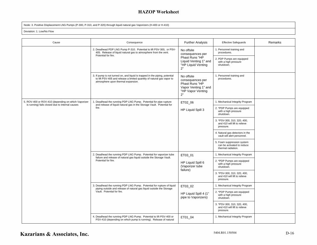
Node: 3. Positive Displacement LNG Pumps (P-300, P-310, and P-320) through liquid natural gas Vaporizers (H-400 or H-410)
Deviation: 1. Low/No Flow
Cause Consequence Further Analysis Effective Safeguards Remarks
1. Personnel training and procedures.
2. PDP Pumps are equipped with a high pressure shutdown.
2. Deadhead PDP LNG Pump P-310. Potential to lift PSV-300, or PSV-405. Release of liquid natural gas to atmosphere from the vent. Potential for fire.
No offsite consequences per Phast Runs "HP Liquid Venting 1" and "HP Liquid Venting 2"
1. Personnel training and procedures.
3. If pump is not turned on, and liquid is trapped in the piping, potential to lift PSV-405 and release a limited quantity of natural gas vapor to atmosphere upon thermal expansion.
No offsite consequences per Phast Runs "HP Vapor Venting 1" and "HP Vapor Venting 2"
1. Mechanical Integrity Program
2. *PDP Pumps are equipped with a high pressure shutdown.
3. *PSV-300, 310, 320, 400, and 410 will lift to relieve pressure.
4. Natural gas detectors in the vault will alert personnel.
5. Foam suppression system can be activated to reduce thermal radiation.
1. Deadhead the running PDP LNG Pump. Potential for pipe rupture and release of liquid natural gas in the Storage Vault. Potential for fire.
ET02_06
HP Liquid Spill 3
1. Mechanical Integrity Program
2. *PDP Pumps are equipped with a high pressure shutdown.
3. *PSV-300, 310, 320, 400, and 410 will lift to relieve pressure.
2. Deadhead the running PDP LNG Pump. Potential for vaporizer tube failure and release of natural gas liquid outside the Storage Vault. Potential for fire.
ET03_01
HP Liquid Spill 6 (Vaporizer tube failure)
1. Mechanical Integrity Program
2. *PDP Pumps are equipped with a high pressure shutdown.
3. *PSV-300, 310, 320, 400, and 410 will lift to relieve pressure.
3. Deadhead the running PDP LNG Pump. Potential for rupture of liquid piping outside and release of natural gas liquid outside the Storage Vault. Potential for fire.
ET03_02
HP Liquid Spill 4 (1" pipe to Vaporizers)
1. Mechanical Integrity Program4. Deadhead the running PDP LNG Pump. Potential to lift PSV-400 or PSV-410 (depending on which pump is running). Release of natural
ET01_04
5. ROV-400 or ROV-410 (depending on which Vaporizer is running) fails closed due to internal causes
HAZOP Worksheet
Kazarians & Associates, Inc. 5404.R01.150504 D-16
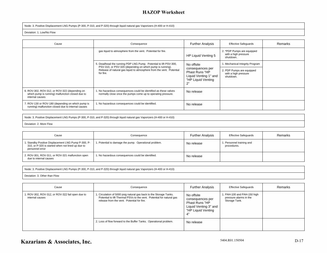
Node: 3. Positive Displacement LNG Pumps (P-300, P-310, and P-320) through liquid natural gas Vaporizers (H-400 or H-410)
Deviation: 1. Low/No Flow
Cause Consequence Further Analysis Effective Safeguards Remarks
2. *PDP Pumps are equipped with a high pressure shutdown.
gas liquid to atmosphere from the vent. Potential for fire.
HP Liquid Venting 5
1. Mechanical Integrity Program
2. PDP Pumps are equipped with a high pressure shutdown.
5. Deadhead the running PDP LNG Pump. Potential to lift PSV-300, PSV-310, or PSV-320 (depending on which pump is running). Release of natural gas liquid to atmosphere from the vent. Potential for fire.
No offsite consequences per Phast Runs "HP Liquid Venting 1" and "HP Liquid Venting 2"
1. No hazardous consequences could be identified as these valves normally close once the pumps come up to operating pressure.
No release6. ROV-302, ROV-312, or ROV-322 (depending on which pump is running) malfunction closed due to internal causes
1. No hazardous consequences could be identified. No release7. ROV-130 or ROV-180 (depending on which pump is running) malfunction closed due to internal causes
Node: 3. Positive Displacement LNG Pumps (P-300, P-310, and P-320) through liquid natural gas Vaporizers (H-400 or H-410)
Deviation: 2. More Flow
Cause Consequence Further Analysis Effective Safeguards Remarks
1. Personnel training and procedures.
1. Potential to damage the pump. Operational problem. No release1. Standby Positive Displacement LNG Pump P-300, P-310, or P-320 is started when not lined up due to personnel error
1. No hazardous consequences could be identified. No release2. ROV-301, ROV-311, or ROV-321 malfunction open due to internal causes
Node: 3. Positive Displacement LNG Pumps (P-300, P-310, and P-320) through liquid natural gas Vaporizers (H-400 or H-410)
Deviation: 3. Other than Flow
Cause Consequence Further Analysis Effective Safeguards Remarks
1. PAH-100 and PAH-150 high pressure alarms in the Storage Tank.
1. Circulation of 5000 psig natural gas back to the Storage Tanks. Potential to lift Thermal PSVs to the vent. Potential for natural gas release from the vent. Potential for fire.
No offsite consequences per Phast Runs "HP Liquid Venting 3" and "HP Liquid Venting 4"
2. Loss of flow forward to the Buffer Tanks. Operational problem. No release
1. ROV-302, ROV-312, or ROV-322 fail open due to internal causes
HAZOP Worksheet
Kazarians & Associates, Inc. 5404.R01.150504 D-17
Node: 3. Positive Displacement LNG Pumps (P-300, P-310, and P-320) through liquid natural gas Vaporizers (H-400 or H-410)
Deviation: 3. Other than Flow
Cause Consequence Further Analysis Effective Safeguards Remarks
1. Mechanical Integrity Program1. Release of natural gas liquid from the vent. Potential for fire. No offsite consequences per Phast Run "HP Liquid Venting 1"
2. PSV-300, PSV-310, or PSV-320 spuriously lift due to internal causes (e.g., broken spring)
1. Mechanical Integrity Program1. Release of natural gas liquid from the vent. Potential for fire. No offsite consequences per Phast Run "HP Liquid Venting 1"
3. PSV-405 spuriously lifts due to internal causes (e.g., broken spring)
1. Mechanical Integrity Program1. Potential for natural gas liquid release from the vent. Potential for fire. No offsite consequences per Phast Run "HP Liquid Venting 1"
4. PSV-400 or PSV-410 spuriously lift due to internal causes (e.g., broken spring)
1. Mechanical Integrity Program
2. *PDP Pumps are equipped with a low pressure shutdown.
3. No sources of mechanical impact.
1. Potential for release of natural gas vapor in the area until personnel intervene and close valve at the storage tank. Potential for fire.
ET06_01
HP Vapor Release 1
1. Mechanical Integrity Program
2. *PDP Pumps are equipped with a low pressure shutdown.
3. No sources of mechanical impact.
2. Potential for release of natural gas vapor in the area until storage tank empties. Potential for fire.
ET06_02
HP Vapor Release 2
3. Potential for loss of flow forward to the Buffer Tanks. Operational problem.
No release
5. H-400 or H-410 Vaporizer tube failure due to internal causes
1. Mechanical Integrity Program1. Potential for natural gas release from the vent. Potential for fire. No offsite consequences per Phast Run "HP Liquid Venting 1"
6. PSV-130, PSV-100, or PSV-150 spuriously lift due to internal causes (e.g., broken spring)
1. Mechanical Integrity Program
2. *PDP Pumps are equipped with a low pressure shutdown.
3. Natural gas detectors in the vault will alert personnel.
4. Foam suppression system
1. Potential for release of natural gas liquid in the Storage Vault. Potential for fire.
ET02_07
HP Liquid Spill 2
7. 3/4" pipe break on the liquid side inside the LNG Storage Vault due to internal causes
HAZOP Worksheet
Kazarians & Associates, Inc. 5404.R01.150504 D-18
Node: 3. Positive Displacement LNG Pumps (P-300, P-310, and P-320) through liquid natural gas Vaporizers (H-400 or H-410)
Deviation: 3. Other than Flow
Cause Consequence Further Analysis Effective Safeguards Remarks
can be activated to reduce thermal radiation.
1. Mechanical Integrity Program
2. *PDP Pumps are equipped with a low pressure shutdown.
3. Natural gas detectors in the vault will alert personnel.
4. Foam suppression system can be activated to reduce thermal radiation.
1. Potential for release of natural gas liquid in the Storage Vault. Potential for fire.
ET02_08
HP Liquid Spill 3
8. 1" pipe break on the liquid side inside the LNG Storage Vault due to internal causes
1. Mechanical Integrity Program
2. *PDP Pumps are equipped with a low pressure shutdown.
3. Natural gas detectors in the vault will alert personnel.
4. Foam suppression system can be activated to reduce thermal radiation.
1. Potential for release of natural gas liquid outside. Potential for fire. ET03_03
HP Liquid Spill 4
9. 1" pipe break on the liquid side outside the LNG Storage Vault due to internal causes
Node: 3. Positive Displacement LNG Pumps (P-300, P-310, and P-320) through liquid natural gas Vaporizers (H-400 or H-410)
Deviation: 4. Misdirected Flow
Cause Consequence Further Analysis Effective Safeguards Remarks
1. Truck driver training and procedures.
1. Release of natural gas liquid from the vent. Potential for fire. No offsite consequences per Phast Runs "LP Liquid Venting 6" and "Storage Tank Spill 2"
1. A drain valve upstream of the Positive Displacement LNG Pumps left open after maintenance
HAZOP Worksheet
Kazarians & Associates, Inc. 5404.R01.150504 D-19
Node: 3. Positive Displacement LNG Pumps (P-300, P-310, and P-320) through liquid natural gas Vaporizers (H-400 or H-410)
Deviation: 5. Reverse Flow
Cause Consequence Further Analysis Effective Safeguards Remarks
1. Potential to send flow up to the discharge point of the standby pump. Flow will not be trapped. Operational problem.
No release1. HCV-78, HCV-79, or HCV-80 (depending on which pump) left open on the standby pump due to personnel error
Node: 3. Positive Displacement LNG Pumps (P-300, P-310, and P-320) through liquid natural gas Vaporizers (H-400 or H-410)
Deviation: 6. High Level
Cause Consequence Further Analysis Effective Safeguards Remarks
1. Not applicable to this node.
Node: 3. Positive Displacement LNG Pumps (P-300, P-310, and P-320) through liquid natural gas Vaporizers (H-400 or H-410)
Deviation: 7. Low Level
Cause Consequence Further Analysis Effective Safeguards Remarks
1. Not applicable to this node.
Node: 3. Positive Displacement LNG Pumps (P-300, P-310, and P-320) through liquid natural gas Vaporizers (H-400 or H-410)
Deviation: 8. High Pressure
Cause Consequence Further Analysis Effective Safeguards Remarks
1. Same consequences as Scenario 1.8.1.1. Fire in the vault from sources other than natural gas
1. Mechanical Integrity Program
2. *PDP Pumps are equipped with a low pressure shutdown.
3. *LNG Pumps are equipped with a low pressure shudown.
4. No sources of fire in the area.
1. Potential for release of natural gas vapor in the area until storage tank empties. Potential for fire.
ET06_13
HP Vapor Release 2
2. Potential to overheat the tubes resulting in tube failure. Potential for loss of flow forward to the Buffer Tanks. Operational problem.
No release
2. Fire near the Vaporizers from sources other than natural gas
HAZOP Worksheet
Kazarians & Associates, Inc. 5404.R01.150504 D-20
Node: 3. Positive Displacement LNG Pumps (P-300, P-310, and P-320) through liquid natural gas Vaporizers (H-400 or H-410)
Deviation: 9. Low Pressure
Cause Consequence Further Analysis Effective Safeguards Remarks
1. No credible causes could be identified within this node.
Node: 3. Positive Displacement LNG Pumps (P-300, P-310, and P-320) through liquid natural gas Vaporizers (H-400 or H-410)
Deviation: 10. Low Temperature
Cause Consequence Further Analysis Effective Safeguards Remarks
1. *TAL-400 or TAL-410 low temperature alarm and shutdown of PDP Pumps.
1. Decreased ability to vaporize liquid natural gas. Potential to send some liquid downstream of the vaporizers. Potential to expose the Priority Panel and Buffer Tanks to low temperature material. Potential for low temperature embrittlement that leads to fracture and failure. Release of natural gas liquid in the area. Potential for fire.
ET03_04
HP Liquid Spill 5
1. H-400 or H-410 Vaporizer fan failure due to internal causes
Node: 3. Positive Displacement LNG Pumps (P-300, P-310, and P-320) through liquid natural gas Vaporizers (H-400 or H-410)
Deviation: 11. High Temperature
Cause Consequence Further Analysis Effective Safeguards Remarks
1. Addressed as part of the High Pressure deviation of this node.
Node: 3. Positive Displacement LNG Pumps (P-300, P-310, and P-320) through liquid natural gas Vaporizers (H-400 or H-410)
Deviation: 12. Contaminants
Cause Consequence Further Analysis Effective Safeguards Remarks
1. No credible causes could be identified within this node.
Node: 3. Positive Displacement LNG Pumps (P-300, P-310, and P-320) through liquid natural gas Vaporizers (H-400 or H-410)
Deviation: 13. What-If
Cause Consequence Further Analysis Effective Safeguards Remarks
1. No additional causes could be identified.
HAZOP Worksheet
Kazarians & Associates, Inc. 5404.R01.150504 D-21
Node: 4. CNG from Vaporizers to Buffer System and Dispensing
Deviation: 1. Low/No Flow
Cause Consequence Further Analysis Effective Safeguards Remarks
1. Mechanical Integrity Program
2. *PDP Pumps are equipped with a high pressure shutdown.
3. *PSV-300, 310, 320, 400, and 410 will lift to relieve pressure.
4. Natural gas detectors in the vault will alert personnel.
5. Foam suppression system can be activated to reduce thermal radiation.
1. Deadhead the running PDP LNG Pump. Potential for pipe rupture and release of liquid natural gas in the Storage Vault. Potential for fire.
ET02_09
HP Liquid Spill 3
1. Mechanical Integrity Program
2. *PDP Pumps are equipped with a high pressure shutdown.
3. *PSV-300, 310, 320, 400, and 410 will lift to relieve pressure.
2. Deadhead the running PDP LNG Pump. Potential for vaporizer tube failure and release of natural gas liquid outside the Storage Vault. Potential for fire.
ET03_05
HP Liquid Spill 6 (Vaporizer tube failure)
1. Mechanical Integrity Program
2. *PDP Pumps are equipped with a high pressure shutdown.
3. *PSV-300, 310, 320, 400, and 410 will lift to relieve pressure.
3. Deadhead the running PDP LNG Pump. Potential for rupture of liquid piping outside and release of natural gas liquid outside the Storage Vault. Potential for fire.
ET03_06
HP Liquid Spill 4 (1" pipe to Vaporizers)
1. Mechanical Integrity Program
2. *PDP Pumps are equipped with a high pressure shutdown.
4. Deadhead the running PDP LNG Pump. Potential to lift PSV-400 or PSV-410 (depending on which pump is running). Release of natural gas liquid to atmosphere from the vent. Potential for fire.
ET01_05
HP Liquid Venting 5
1. Mechanical Integrity Program
2. PDP Pumps are equipped with a high pressure shutdown.
5. Deadhead the running PDP LNG Pump. Potential to lift PSV-300, PSV-310, or PSV-320 (depending on which pump is running). Release of natural gas liquid to atmosphere from the vent. Potential for fire.
No offsite consequences per Phast Runs "HP Liquid Venting 1" and "HP Liquid Venting 2"
1. ROV-500 or ROV-510 left closed due to personnel error
1. It is assumed that the path to all other Buffer Tank relief valves
1. Blocked flow to the associated relief valve. Operational problem. No release2. HCV-71, HCV-72, HCV-73, HCV-74, HCV-75, or HCV-76 left closed due to personnel error
HAZOP Worksheet
Kazarians & Associates, Inc. 5404.R01.150504 D-22

Node: 4. CNG from Vaporizers to Buffer System and Dispensing
Deviation: 1. Low/No Flow
Cause Consequence Further Analysis Effective Safeguards Remarks
remain open.
1. Blocked flow to one of the Buffer Tanks. Reduced pressurized buffer storage capacity. Operational problem.
No release3. HCV-61, HCV-62, HCV-63, HCV-64, HCV-65, or HCV-66 left closed due to personnel error
1. Mechanical Integrity Program
2. *PDP Pumps are equipped with a high pressure shutdown.
3. *PSV-300, 310, 320, 400, and 410 will lift to relieve pressure.
4. Natural gas detectors in the vault will alert personnel.
5. Foam suppression system can be activated to reduce thermal radiation.
1. Deadhead the running PDP LNG Pump. Potential for pipe rupture and release of liquid natural gas in the Storage Vault. Potential for fire.
ET02_10
HP Liquid Spill 3
1. Mechanical Integrity Program
2. *PDP Pumps are equipped with a high pressure shutdown.
3. *PSV-300, 310, 320, 400, and 410 will lift to relieve pressure.
2. Deadhead the running PDP LNG Pump. Potential for vaporizer tube failure and release of natural gas liquid outside the Storage Vault. Potential for fire.
ET03_07
HP Liquid Spill 6 (Vaporizer tube failure)
1. Mechanical Integrity Program
2. *PDP Pumps are equipped with a high pressure shutdown.
3. *PSV-300, 310, 320, 400, and 410 will lift to relieve pressure.
3. Deadhead the running PDP LNG Pump. Potential for rupture of liquid piping outside and release of natural gas liquid outside the Storage Vault. Potential for fire.
ET03_08
HP Liquid Spill 4 (1" pipe to Vaporizers)
1. Mechanical Integrity Program
2. *PDP Pumps are equipped with a high pressure shutdown.
4. Deadhead the running PDP LNG Pump. Potential to lift PSV-400 or PSV-410 (depending on which pump is running). Release of natural gas liquid to atmosphere from the vent. Potential for fire.
ET01_05
HP Liquid Venting 5
1. Mechanical Integrity Program
2. PDP Pumps are equipped with a high pressure shutdown.
5. Deadhead the running PDP LNG Pump. Potential to lift PSV-300, PSV-310, or PSV-320 (depending on which pump is running). Release of natural gas liquid to atmosphere from the vent. Potential for fire.
No offsite consequences per Phast Runs "HP Liquid Venting 1" and "HP Liquid Venting 2"
4. A control valve in the Priority Panel malfunctions closed due to internal error
HAZOP Worksheet
Kazarians & Associates, Inc. 5404.R01.150504 D-23
Node: 4. CNG from Vaporizers to Buffer System and Dispensing
Deviation: 2. More Flow
Cause Consequence Further Analysis Effective Safeguards Remarks
1. Two separate control valves would need to malfunction open in order for an increased flow scenario to occur. This is not credible.
1. 1. No credible causes could be identified within this node.
Node: 4. CNG from Vaporizers to Buffer System and Dispensing
Deviation: 3. Other than Flow
Cause Consequence Further Analysis Effective Safeguards Remarks
1. Mechanical Integrity Program1. Release of natural gas vapor to atmosphere. Potential for fire. ET01_01
Buffer PSV Lift 2
1. A Buffer Tank PSV spuriously lifts due to internal causes (e.g., broken spring)
1. Mechanical Integrity Program
2. *PDP Pumps are equipped with a low pressure shutdown.
1. Release of natural gas vapor in the area until personnel intervene and close valve at the storage tank. Potential for fire.
ET06_03
HP Vapor Release 3
1. Mechanical Integrity Program
2. *PDP Pumps are equipped with a low pressure shutdown.
2. Release of natural gas vapor in the area until storage tank empties. Potential for fire.
ET06_04
HP Vapor Release 4
2. Break of the 1" CNG pipe in the system due to internal causes
1. Mechanical Integrity Program
2. *PDP Pumps are equipped with a low pressure shutdown.
1. Release of natural gas vapor in the area until personnel intervene and close valve at the storage tank. Potential for fire.
ET06_05
Bus Fueling Release 1
1. Mechanical Integrity Program
2. *PDP Pumps are equipped with a low pressure shutdown.
2. Release of natural gas vapor in the area until storage tank empties. Potential for fire.
ET06_06
Bus Fueling Release 2
1. No event tree was created for this scenario as it is directional. If the direction of the release is towards the operator at the dispenser, then
3. Potential for bus unloading operator exposure to high pressure natural gas. Potential for injury.
N/A
3. Leak/rupture of hose at Dispensing Station during CNG loading onto a bus due to internal causes
HAZOP Worksheet
Kazarians & Associates, Inc. 5404.R01.150504 D-24
Node: 4. CNG from Vaporizers to Buffer System and Dispensing
Deviation: 3. Other than Flow
Cause Consequence Further Analysis Effective Safeguards Remarks
an injury will occur.
1. Mechanical Integrity Program1. Release of natural gas vapor to atmosphere. Potential for fire. ET06_09
Bus Fueling Release 5
4. A Fueling Area PSV spuriously lifts due to internal causes (e.g., broken spring)
Node: 4. CNG from Vaporizers to Buffer System and Dispensing
Deviation: 4. Misdirected Flow
Cause Consequence Further Analysis Effective Safeguards Remarks
1. No credible causes could be identified within this node.
Node: 4. CNG from Vaporizers to Buffer System and Dispensing
Deviation: 5. Reverse Flow
Cause Consequence Further Analysis Effective Safeguards Remarks
1. No credible causes could be identified within this node.
Node: 4. CNG from Vaporizers to Buffer System and Dispensing
Deviation: 6. High Level
Cause Consequence Further Analysis Effective Safeguards Remarks
1. Not applicable to this node.
Node: 4. CNG from Vaporizers to Buffer System and Dispensing
Deviation: 7. Low Level
Cause Consequence Further Analysis Effective Safeguards Remarks
1. Not applicable to this node.
HAZOP Worksheet
Kazarians & Associates, Inc. 5404.R01.150504 D-25
Node: 4. CNG from Vaporizers to Buffer System and Dispensing
Deviation: 8. High Pressure
Cause Consequence Further Analysis Effective Safeguards Remarks
1. No sources of fire in the area. 1. All natural gas related fire events have been postulated as part of other scenarios (e.g., flange leaks).
1. Potential to overheat the tanks and increase pressure resulting in tank rupture. Potential for pressure wave and flash fire.
ET05_01
HP Vapor Release 8
1. No sources of fire in the area.2. Potential to overheat the tanks and increase pressure. Potential to lift the relief valves on the Buffer Tanks. Release of natural gas vapor in the area. Potential for fire.
ET01_03
Buffer PSV Lift 1
3. Potential to overheat the tanks and increase pressure resulting in tank rupture. Potential for loss of flow forward to the Dispensing Area. Operational problem.
No release
1. Fire near the Buffer Tanks from sources other than natural gas
1. Mechanical Integrity Program1. Potential to lift a relief valve with the Buffer Tank System. Release of natural gas vapor in the area. Potential for fire.
ET01_02
Buffer PSV Lift 1
2. Priority Panel malfunction sending more CNG than necessary to a Buffer Tank
1. Mechanical Integrity Program
2. *High pressure shutdown.
1. Release of natural gas vapor in the area from the Fueling Area relief valve until personnel intervene and close valve at the storage tank. Potential for fire.
ET06_07
Bus Fueling Release 3
1. Mechanical Integrity Program
2. *High pressure shutdown.
2. Release of natural gas vapor in the area from the Fueling Area relief valve until storage tank empties. Potential for fire.
ET06_08
Bus Fueling Release 4
3. Priority Panel malfunctions causing increased pressure within the Fueling Area piping
Node: 4. CNG from Vaporizers to Buffer System and Dispensing
Deviation: 9. Low Pressure
Cause Consequence Further Analysis Effective Safeguards Remarks
1. No credible causes could be identified within this node.
Node: 4. CNG from Vaporizers to Buffer System and Dispensing
Deviation: 10. Low Temperature
Cause Consequence Further Analysis Effective Safeguards Remarks
1. No credible causes could be identified within this
HAZOP Worksheet
Kazarians & Associates, Inc. 5404.R01.150504 D-26
Node: 4. CNG from Vaporizers to Buffer System and Dispensing
Deviation: 10. Low Temperature
Cause Consequence Further Analysis Effective Safeguards Remarks
node.
Node: 4. CNG from Vaporizers to Buffer System and Dispensing
Deviation: 11. High Temperature
Cause Consequence Further Analysis Effective Safeguards Remarks
1. Addressed as part of the High Pressure deviation of this node.
Node: 4. CNG from Vaporizers to Buffer System and Dispensing
Deviation: 12. Contaminants
Cause Consequence Further Analysis Effective Safeguards Remarks
1. No credible causes could be identified within this node.
Node: 4. CNG from Vaporizers to Buffer System and Dispensing
Deviation: 13. What-If
Cause Consequence Further Analysis Effective Safeguards Remarks
1. Personnel training and procedures.
1. Potential for tank rupture. Potential for personnel exposure. ET06_10
HP Vapor Release 6
1. Personnel training and procedures.
2. Potential for 2" leak from a tank. Potential for personnel exposure. ET06_11
HP Vapor Release 7
1. A Buffer Tank is struck by a moving vehicle due to personnel error
1. Personnel training and procedures.
2. *PDP Pumps are equipped with a low pressure shutdown.
1. Potential for release of natural gas. Potential for fire. ET06_12
HP Vapor Release 5
2. CNG pipe is struck by a moving vehicle due to personnel error
HAZOP Worksheet
Kazarians & Associates, Inc. 5404.R01.150504 D-27
Node: 5. Truck offloading to LNG Storage Tanks (V-100 and V-150)
Deviation: 1. Low/No Flow
Cause Consequence Further Analysis Effective Safeguards Remarks
1. Personnel training and procedures.
2. Pressure indication on the tanker truck.
1. Pressure increase on the truck. Potential to lift the relief valve (set at 70 psig) on the truck. Release of natural gas. Potential for fire.
No offsite consequences per Phast Runs "Tanker PSV Lift 1" and "Tanker PSV Lift 2"
1. HCV-1 or HCV-22 not opened prior to offloading from the tanker truck due to driver error
1. Mechanical Integrity Program
2. Personnel training and procedures.
3. PI-220 pressure indication.
1. Blocked flow at the outlet of the running LNG Pump. Potential to lift PSV-220-2. Potential for release of natural gas liquid to atmosphere from the vent. Potential for fire.
No offsite consequences per Phast Run "Storage Tank Spill 5"
2. ROV-220 malfunctions closed due to internal causes
1. Mechanical Integrity Program
2. Personnel training and procedures.
3. PI-220 pressure indication.
1. Blocked flow at the outlet of the running LNG Pump. Potential to lift PSV-220-2 and PSV-110. Potential for release of natural gas liquid to atmosphere from the vent. Potential for fire.
No offsite consequences per Phast Run "Storage Tank Spill 5"
3. ROV-110 malfunctions closed when filling V-100 due to internal causes
1. Mechanical Integrity Program
2. Personnel training and procedures.
3. PI-220 pressure indication.
1. Blocked flow at the outlet of the running LNG Pump. Potential to lift PSV-220-2 and PSV-110. Potential for release of natural gas liquid to atmosphere from the vent. Potential for fire.
No offsite consequences per Phast Run "Storage Tank Spill 5"
4. HCV-3 closed prior to offloading from the tanker truck when filling V-100 or HCV-3-1 closed prior to offloading from the tanker truck when filling V-150 due to driver error
1. Mechanical Integrity Program
2. Personnel training and procedures.
3. PI-220 pressure indication.
1. Blocked flow at the outlet of the running LNG Pump. Potential to lift PSV-220-2 and PSV-110. Potential for release of natural gas liquid to atmosphere from the vent. Potential for fire.
No offsite consequences per Phast Run "Storage Tank Spill 5"
5. ROV-160 malfunctions closed when filling V-150 due to internal causes
Node: 5. Truck offloading to LNG Storage Tanks (V-100 and V-150)
Deviation: 2. More Flow
Cause Consequence Further Analysis Effective Safeguards Remarks
1. No credible causes could be identified within this node.
HAZOP Worksheet
Kazarians & Associates, Inc. 5404.R01.150504 D-28
Node: 5. Truck offloading to LNG Storage Tanks (V-100 and V-150)
Deviation: 3. Other than Flow
Cause Consequence Further Analysis Effective Safeguards Remarks
1. Mechanical Integrity Program
2. Truck driver training and procedures to close the supply valve upon release.
1. Release of natural gas liquid to atmosphere from the vent. Potential for fire.
No offsite consequences per Phast Run "LP Liquid Venting 4"
1. PSV-240 or PSV-230 spuriously lift during offloading due to internal causes (e.g., broken spring)
1. Mechanical Integrity Program
2. Truck driver training and procedures to close the supply valve upon release.
1. Release of natural gas liquid to atmosphere from the vent. Potential for fire.
No offsite consequences per Phast Run "LP Liquid Venting 4"
2. PSV-220-2, PSV-110, PSV-150, or PSV-160 spuriously lift during offloading due to internal causes (e.g., broken spring)
1. Mechanical Integrity Program
2. Truck driver training and procedures to close the supply valve upon release.
1. Release of natural gas vapor to atmosphere from the vent. Potential for fire.
No offsite consequences per Phast Run "LP Liquid Venting 4"
3. PSV-220 or PSV-250 spuriously lift during offloading due to internal causes (e.g., broken spring)
1. Mechanical Integrity Program1. Release of natural gas vapor to atmosphere from the vent. Potential for fire.
No offsite consequences per Phast Runs "Tanker PSV Lift 1" and "Tanker PSV Lift 2"
4. A PSV on the tanker truck spuriously lifts during offloading due to internal causes (e.g., broken spring)
1. Mechanical Integrity Program of the vendor
2. *Truck driver training and procedures to close the supply valve upon release.
1. Release of natural gas liquid from the tanker until the emergency stop valve closes. Potential for fire.
ET04_01
Tanker Spill 1
5. Loading hose rupture due to improper hose maintenance, internal causes, early disconnection, or truck movement during unloading for any reason and driver is able to push the emergency stop in less than 30 seconds
1. Mechanical Integrity Program of the vendor
2. *Truck driver training and procedures to close the supply valve upon release.
1. Release of natural gas liquid from the tanker until empty. Potential for fire.
ET04_02
Tanker Spill 2
6. Loading hose rupture due to improper hose maintenance, internal causes, early disconnection, or truck movement during unloading for any reason and driver is unable to push the emergency stop
1. Mechanical Integrity Program
2. Truck driver training and procedures to close the supply valve upon release.
1. Release of small amount of natural gas liquid from the tanker. Potential for fire.
No offsite consequences per Phast Runs "Tanker Spill 3" and "Tanker Spill 4"
7. Small hose leak during unloading due to internal causes or poor hose connection
1. Mechanical Integrity Program
2. Natural gas detectors in the vault will alert personnel.
3. Foam suppression system can be activated to reduce thermal radiation.
1. Release of natural gas vapor in the Storage Vault. Potential for fire. No offsite consequences per Phast Runs "LP Vapor Release 1" and "LP Vapor Release 2"
8. Leakage of a pipe on the vapor side (e.g., flange leak on a vapor side valve) due to internal causes
HAZOP Worksheet
Kazarians & Associates, Inc. 5404.R01.150504 D-29

Node: 5. Truck offloading to LNG Storage Tanks (V-100 and V-150)
Deviation: 3. Other than Flow
Cause Consequence Further Analysis Effective Safeguards Remarks
1. Mechanical Integrity Program of the vendor
2. *Truck driver training and procedures to close the supply valve upon release.
1. Release of natural gas liquid from the tanker until the emergency stop valve closes. Potential for fire.
ET02_11
Tanker Spill 6
9. Leakage of a pipe on the liquid side within the LNG Storage Vault during delivery (3" pipe break) due to internal causes and driver is able to push the emergency stop in less than 30 seconds
1. Mechanical Integrity Program of the vendor
2. *Truck driver training and procedures to close the supply valve upon release.
3. Natural gas detectors in the vault will alert personnel.
4. Foam suppression system can be activated to reduce thermal radiation.
1. Release of natural gas liquid from the tanker until empty. Potential for fire.
ET02_12
Tanker Spill 7
10. Leakage of a pipe on the liquid side within the LNG Storage Vault during delivery (3" pipe break) due to internal causes and driver is unable to push the emergency stop
1. Mechanical Integrity Program1. Release of natural gas vapor to atmosphere from the vent. Potential for fire.
No offsite consequences per Phast Run "Tanker Spill 4"
11. PSV-200 spuriously lifts due to internal causes (e.g., broken spring) during filling operation
1. Mechanical Integrity Program1. Release of natural gas liquid in the area. Potential for fire. ET04_03
Tanker Spill 9
12. Break of tanker while onsite
Node: 5. Truck offloading to LNG Storage Tanks (V-100 and V-150)
Deviation: 4. Misdirected Flow
Cause Consequence Further Analysis Effective Safeguards Remarks
1. *Truck driver training and procedures.
1. Release of natural gas liquid from the vent to atmosphere. Potential for fire.
ET01_07
LP Liquid Venting 3
1. HCV-21 left open for too long during delivery due truck driver error or HCV-31a and HCV-27 left open after P-220 Pump Pot is full or HCV-31 left open after P-210 Pump Pot is full due truck driver error
1. Truck driver training and procedures.
1. Release of natural gas liquid from the vent to atmosphere. Potential for fire.
No offsite consequences per Phast Run "Tanker Spill 5"
2. HCV-26 inadvertently left open during delivery due truck driver error
HAZOP Worksheet
Kazarians & Associates, Inc. 5404.R01.150504 D-30
Node: 5. Truck offloading to LNG Storage Tanks (V-100 and V-150)
Deviation: 5. Reverse Flow
Cause Consequence Further Analysis Effective Safeguards Remarks
1. No credible causes could be identified within this node.
Node: 5. Truck offloading to LNG Storage Tanks (V-100 and V-150)
Deviation: 6. High Level
Cause Consequence Further Analysis Effective Safeguards Remarks
1. *Truck driver training and procedures.
1. Increase level and pressure in the affected LNG Storage Tank. Potential to lift the relief valve on the LNG Storage Tank. Release of natural gas liquid from the vent. Potential for fire.
ET01_06
Tanker Spill 8
LP Liquid Venting 5
1. Truck driver lines up tanker truck to wrong Storage Tank (i.e., tank that is already 90% full) instead of empty one or truck driver does not shut off transfer operation when the Storage Tank is full
Node: 5. Truck offloading to LNG Storage Tanks (V-100 and V-150)
Deviation: 7. Low Level
Cause Consequence Further Analysis Effective Safeguards Remarks
1. It is assumed that pump seal leakage will not occur as the pumps are submerged in a pump pot.
1. Insufficient natural gas liquid to the pumps. Potential to cavitate the pumps in the system. Operational problem.
No release1. LNG Storage Tanks not filled in a timely manner due to truck driver error
Node: 5. Truck offloading to LNG Storage Tanks (V-100 and V-150)
Deviation: 8. High Pressure
Cause Consequence Further Analysis Effective Safeguards Remarks
1. Personnel training and procedures.
2. Pressure indication on the tanker truck.
1. Potential to lift the relief valve (set at 70 psig) on the truck. Release of natural gas. Potential for fire.
No offsite consequences per Phast Run "Tanker PSV Lift 2"
1. Truck driver error in exceeding 60 psig within the tanker truck system during pressure buildup
1. Housekeeping practices.
2. High pressure alarm.
1. Increase pressure in the LNG Truck. Potential to lift a relief valve. Release of natural gas vapor from the vent. Potential for fire.
No offsite consequences per Phast Run "Tanker
2. Fire near the LNG Truck from sources other than natural gas
HAZOP Worksheet
Kazarians & Associates, Inc. 5404.R01.150504 D-31
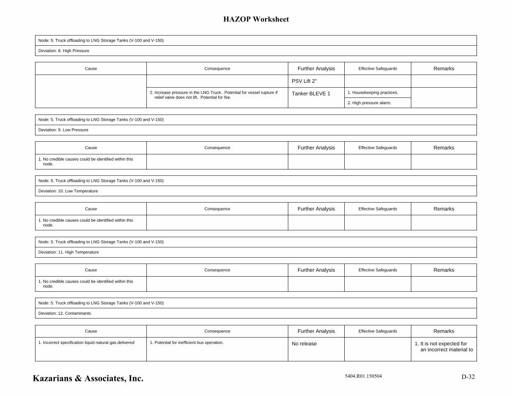
Node: 5. Truck offloading to LNG Storage Tanks (V-100 and V-150)
Deviation: 8. High Pressure
Cause Consequence Further Analysis Effective Safeguards Remarks
PSV Lift 2"
1. Housekeeping practices.
2. High pressure alarm.
2. Increase pressure in the LNG Truck. Potential for vessel rupture if relief valve does not lift. Potential for fire.
Tanker BLEVE 1
Node: 5. Truck offloading to LNG Storage Tanks (V-100 and V-150)
Deviation: 9. Low Pressure
Cause Consequence Further Analysis Effective Safeguards Remarks
1. No credible causes could be identified within this node.
Node: 5. Truck offloading to LNG Storage Tanks (V-100 and V-150)
Deviation: 10. Low Temperature
Cause Consequence Further Analysis Effective Safeguards Remarks
1. No credible causes could be identified within this node.
Node: 5. Truck offloading to LNG Storage Tanks (V-100 and V-150)
Deviation: 11. High Temperature
Cause Consequence Further Analysis Effective Safeguards Remarks
1. No credible causes could be identified within this node.
Node: 5. Truck offloading to LNG Storage Tanks (V-100 and V-150)
Deviation: 12. Contaminants
Cause Consequence Further Analysis Effective Safeguards Remarks
1. It is not expected for an incorrect material to
1. Potential for inefficient bus operation. No release1. Incorrect specification liquid natural gas delivered
HAZOP Worksheet
Kazarians & Associates, Inc. 5404.R01.150504 D-32
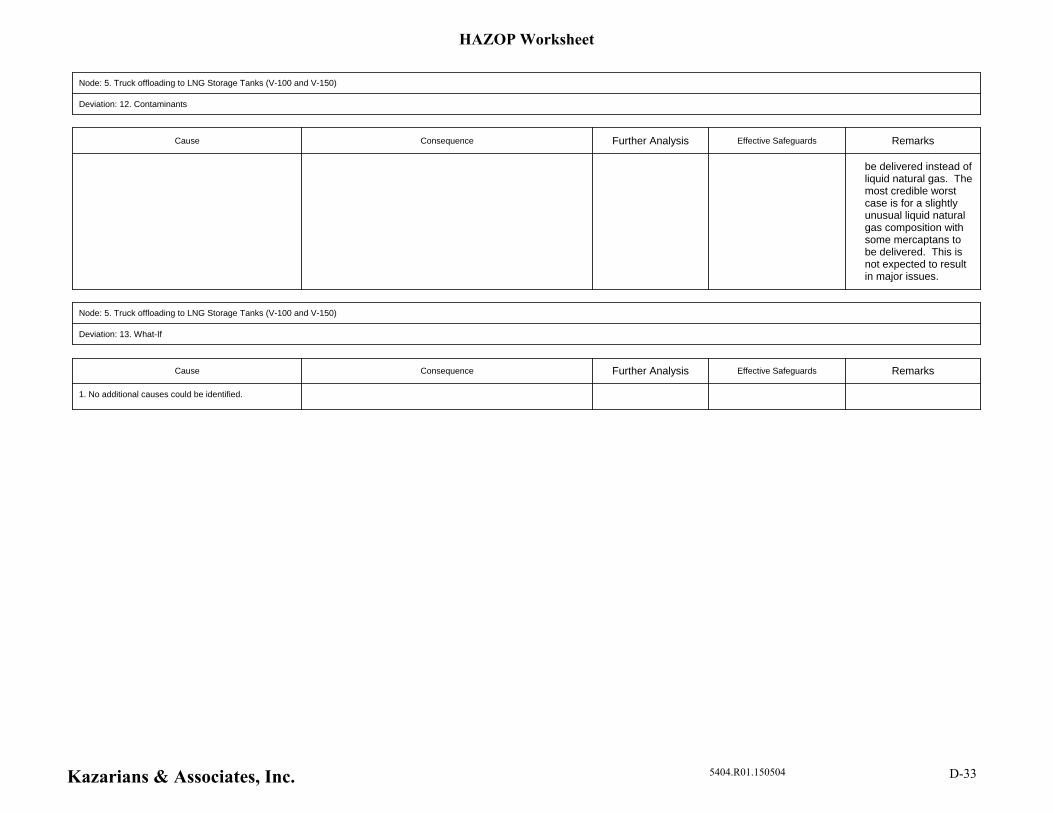
Node: 5. Truck offloading to LNG Storage Tanks (V-100 and V-150)
Deviation: 12. Contaminants
Cause Consequence Further Analysis Effective Safeguards Remarks
be delivered instead of liquid natural gas. The most credible worst case is for a slightly unusual liquid natural gas composition with some mercaptans to be delivered. This is not expected to result in major issues.
Node: 5. Truck offloading to LNG Storage Tanks (V-100 and V-150)
Deviation: 13. What-If
Cause Consequence Further Analysis Effective Safeguards Remarks
1. No additional causes could be identified.
HAZOP Worksheet
Kazarians & Associates, Inc. 5404.R01.150504 D-33

Appendix E – Exposure Thresholds
APPENDIX E - EXPOSURE THRESHOLDS
In the analysis presented in this report, potential impact to the population is classified in terms of exposure thresholds. There are two potential sources of impact to the population: overpressure due to explosion, and thermal radiation due to fire. Each threat has a unique hazard zone that is determined by its effects on both the human body and surrounding structures. E.1 OVERPRESSURE EXPOSURE
If a vapor cloud which is within the flammable region contacts an ignition source, there is the possibility of a detonation. In the event of a detonation, rapid combustion generates a high flame speed, which results in a rapidly expanding pressure wave. This pressure wave has the potential to have an impact on both buildings and personnel, depending on the extent of overpressure. Damage to humans as a result of this pressure wave is typically divided into three categories: Primary, Secondary, and Tertiary [Reference E-1]. Primary damage is defined as damage to the human body directly resulting from the rapid overpressure. Secondary damage encompasses impact to humans due to projectiles or structural damage resulting from the pressure wave. Finally, tertiary damage is a result of physical movement of the body due to the explosion (e.g., striking the head on the ground). Sources provide a wide range of estimates for the correlation between the maximum overpressure and impact on people and structures. Table E-1 provides a matrix of possible damage scenarios and the maximum overpressure at which they may occur, categorized by the reference from which the information was obtained.
Table E-1 – Overpressure Impacts by Reference
Failure Type Maximum Overpressure (Psi)
0.15 0.5 1 2 3.5 5 7 8 15 35
Glass Breaks 3, 5
Windows Shatter 2,3,5 4
People Knocked Down 2
Cinder Block Walls Fail 2,3,5
Partial Collapse of Walls/Roofs 3,5
Rupture Eardrums 4 2
Homes Destroyed 3,5 4
Brick Walls Fail 2,3
Lung Damage 2
Lung Collapse (Fatality) 1 5 2
For the purposes of this report, three major thresholds are presented in the analysis, which can be found in Table E-2 below.
Table E-2 – Overpressure Exposure Thresholds
Maximum Overpressure Impact
0.5 psi Windows Break (possible slight injuries)
2 psi Structural Damage to Homes (possible injury or fatality)
5 psi Homes Destroyed (probable fatalities), Eardrums Ruptured
While sources present varying pressure thresholds for the breaking of glass and windows, 0.5 psi is chosen as an estimate of the normal pressure at which most windows will shatter. ALOHA modelling software [Reference E-4] was developed by the U.S. Environmental Protection Agency specifically for use in determining potential impact on the public due to the accidental release of a hazardous substance. As noted in Table E-1, ALOHA uses a threshold of 1.0 psig for shattered windows. Taking this into account, 0.5 psi is chosen as a more conservative threshold for the breaking of glass. For the second overpressure threshold, 2 psi is used to demonstrate the point at which walls and roofs may sustain structural damage significant enough to cause severe injuries or even a fatality. For the purposes of this report, it is assumed that at an overpressure of 2 psi or greater, fatalities may occur due to the impact of the pressure wave on surrounding structures. The final damage threshold was chosen as 5 psi to represent the point at which homes will be totally destroyed. Above this point, it is assumed that personnel will not survive the blast, as there will be a very high potential for impact from shrapnel or collapsing buildings. E.2 THERMAL RADIATION
The other primary concern in the event of a natural gas release is thermal radiation. Typically, thermal radiation is measured in terms of thermal flux, which is measured in terms of energy per unit area. Additionally, damage to personnel is based on exposure length. A longer exposure time will lead to an increase in injury severity. This means that to determine the consequence of heat exposure, the potential damage thresholds will vary based on exposure time. As a conservative measure, ALOHA modeling software [Reference E-4] uses a 60 second exposure time to determine the potential impact on personnel. Table E-3 presents the effects of exposure at varying thermal radiation levels, grouped by reference source.

Table E-3 – Thermal Radiation Impacts by Reference
Impact on Humans Thermal Radiation Flux (kW/m2)
1.2 2 5 9.5 10 12.5 20 35 37.5
Normal Solar Radiation 1,6,7
Pain at 60 seconds 1,4,6
Injury after 30 seconds 6,7,8
Second Degree Burn after 60 sec 4
Second degree burn after 20 sec 6 1
Lethal within 60 seconds 4
Incapacitation 1
Immediate fatality 1 7 Note that these effects and exposure times are only applicable for personnel who are in direct contact with the heat source. Personnel located within buildings or behind walls will experience a lower thermal flux, and will therefore experience less severe injuries. For the purposes of this report, the thermal radiation damage thresholds listed in Table E-4 below are used to determine the potential impact on the public as a result of exposure to a fire.
Table E-4 - Thermal Radiation Exposure Thresholds
Thermal Radiation Flux Impact
2 (kW/m2) Pain from exposure for 60 seconds
5 (kW/m2) Second degree burns at 60 seconds (minor injury at 30 seconds)
10 (kW/m2) Lethal within 60 seconds (possible fatality)
The thermal radiation thresholds used are the same as those used in the EPA’s ALOHA software. These thresholds are conservative in that they are intended for a 60 second exposure time, meaning that personnel must be unable to evacuate themselves from the area in order for the listed effects to occur. E.3 REFERENCES
E-1. OGP Risk Assessment Data Directory: Vulnerability of Humans. The International Association of Oil and Gas Producers. Report No. 434-14.1. March 2010.
E-2 Toups, Harry J., Fires and Explosions - Fundamentals and Design Considerations
[PowerPoint Slides]. Retrieved February 26, 2015 from www.sache.org / links / Pike21Jul2004 / Fires%20and%20Explosions.ppt.

E-3 Clancey V J, 1972. Diagnostic features of explosion damage, 6th Intl. Meeting on Forensic Sciences, Edinburgh, Scotland.
E-4 ALOHA 5.4.3 Modelling Software, Office of Emergency Management – U.S. EPA and
Emergency Response Division Division – National Oceanic and Atmospheric Administration.
E-5 Handbook of Chemical Hazard Analysis Procedures. Federal Emergency Management
Agency, U.S. Department of Transportation, U.S. Environmental Protection Agency. E-6 Hockey, S M, and P J Rew. Review of Human Response to Thermal Radiation. HSE
Contract Research Report No. 97/1996. Health and Safety Executive. July 2, 1996. E-7 Raj, Phani K. A Review of the Criteria for People Exposure to Radiant Heat Flux from
Fires. Technology & Management Systems, Inc. October 25, 2006. E-8 National Fire Protection Association. (2013). NFPA 59A: Standard for the Production,
Storage, and Handling of Liquefied Natural Gas (LNG).

Appendix F – Weather Data

Kazarians & Associates, Inc. 5404.R01.150504 F-1
APPENDIX F - WEATHER DATA
Historical weather data is used in this report to identify the typical range of weather conditions which may be encountered at the facility. Wind data from the Rialto Air Monitoring Station indicates an average wind speed of 3.46 meters per second (7.74 mph), and a normal wind direction of West-Southwest. Strong winds, however, come primarily from the North or North-Northeast.
Figure F-1 – Rialto Air Monitoring Station Wind Rose
Historical temperature and pressure data can be found in Table F-3 at the end of this appendix. This data is taken from the San Bernardino, California weather station located at a latitude and longitude of N 34°6’21”, W 117°17’49” (Station ID MSDSBO) [Reference F-1]. The data was collected between the period of February 18, 2014 and February 18, 2015.
WIND ROSE PLOT
Station #54166 - , 1981
NORTH
SOUTH
WEST EAST
5%
10%
15%
20%
25%
Wind Speed (m/s)
> 11.06
8.49 - 11.06
5.40 - 8.49
3.34 - 5.40
1.80 - 3.34
0.51 - 1.80
COMPANY NAMEMODELER
PLOT YEAR-DATE-TIME
1981 Jan 1 - Dec 31Midnight - 11 PM
DATE
5/29/2003
DISPLAY
Wind Speed
UNIT
m/s
CALM WINDS
2.42%
AVG. WIND SPEED
3.46 m/s
COMMENTS
PROJECT/PLOT NO.
1981
ORIENTATION
Direction(blowing from)
WRPLOT View 3.5 by Lakes Environmental Software - www.lakes-environmental.com

Kazarians & Associates, Inc. 5404.R01.150504 F-2
From the data, three distinct weather conditions are taken for analysis in this report. The first is “Category 1.5/F.” This category is taken directly from the EPA’s guidance on defining weather conditions for a worst-case release scenario [Reference F-2]. The EPA specifies that a wind speed of 1.5 m/s and an atmospheric stability class of F shall be used, along with the maximum recorded temperature. From Table F-3, the maximum recorded temperature is 104°F. The second weather category, “Average Conditions” is taken from the average wind speed of 3.46 m/s from Figure F-1, and the corresponding D stability class, as well as the average temperature of 70°F from Table F-3. “Santa Ana Conditions” represent the warm, high speed winds common to the San Bernardino area. As reflected in the wind rose, high wind speeds (above 11.06 m/s) come almost exclusively from the North or North-Northeast. To capture this weather condition, Santa Ana Conditions are defined as having a wind speed of 12 m/s, and an atmospheric stability class of D, as well as a temperature of 90°F. In the dispersion modeling, all three weather conditions are analyzed for each release scenario. In order to determine the frequency of a given consequence, the relative probability of occurrence of each weather condition must be taken into account. From the wind rose in Figure F-1, the percentage of occurrence of each category can be obtained. For the purposes of this calculation, “Category 1.5/F” is taken to be the 0.5-1.8 m/s region of Figure F-1, “Average Conditions” are taken to be the 1.80-11.06 m/s regions, and “Santa Ana Conditions” are taken to be the > 11.06 m/s region. Table F-1 below demonstrates the breakdown of wind conditions based on Figure F-1.
Table F-1 – Percent Distribution of Wind Conditions
Direction Category 1.5/F Average
Conditions Santa Ana Conditions
N 2 6.5 3.5 NNW 2.5 2.5 0 NW 3 2 0
WNW 3.5 1.5 0 W 4 9 0
WSW 4.5 16.5 0 SE 4 4 0
SSW 1.5 0.5 0 S 1.5 1 0
SSE 2 0.5 0 SE 1.5 0.5 0
ESE 1 0.5 0 E 1 0.5 0
ENE 2 1 0 NE 2.5 4.5 0.5
NNE 2.5 5 1 Total 39 56 5
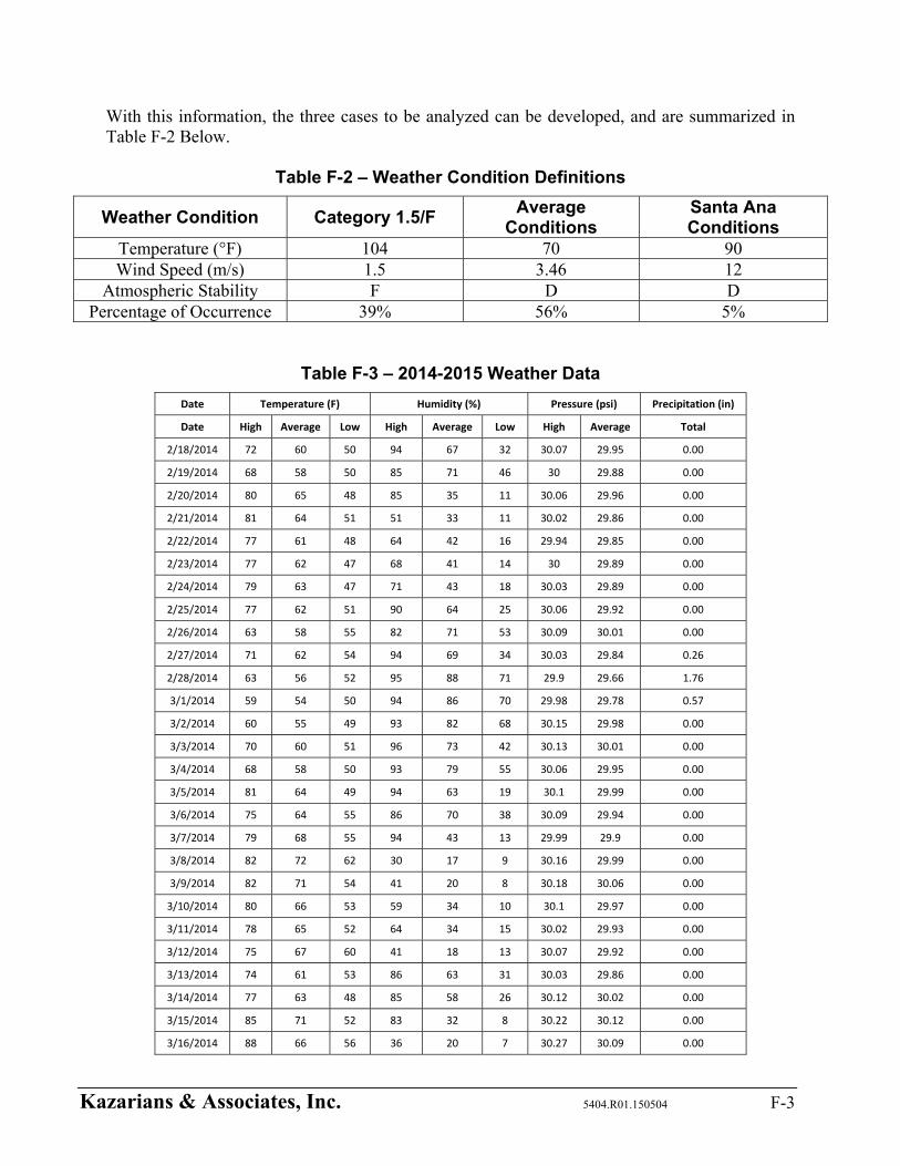
Kazarians & Associates, Inc. 5404.R01.150504 F-3
With this information, the three cases to be analyzed can be developed, and are summarized in Table F-2 Below.
Table F-2 – Weather Condition Definitions
Weather Condition Category 1.5/F Average
Conditions Santa Ana Conditions
Temperature (°F) 104 70 90 Wind Speed (m/s) 1.5 3.46 12
Atmospheric Stability F D D Percentage of Occurrence 39% 56% 5%
Table F-3 – 2014-2015 Weather Data
Date Temperature (F) Humidity (%) Pressure (psi) Precipitation (in)
Date High Average Low High Average Low High Average Total
2/18/2014 72 60 50 94 67 32 30.07 29.95 0.00
2/19/2014 68 58 50 85 71 46 30 29.88 0.00
2/20/2014 80 65 48 85 35 11 30.06 29.96 0.00
2/21/2014 81 64 51 51 33 11 30.02 29.86 0.00
2/22/2014 77 61 48 64 42 16 29.94 29.85 0.00
2/23/2014 77 62 47 68 41 14 30 29.89 0.00
2/24/2014 79 63 47 71 43 18 30.03 29.89 0.00
2/25/2014 77 62 51 90 64 25 30.06 29.92 0.00
2/26/2014 63 58 55 82 71 53 30.09 30.01 0.00
2/27/2014 71 62 54 94 69 34 30.03 29.84 0.26
2/28/2014 63 56 52 95 88 71 29.9 29.66 1.76
3/1/2014 59 54 50 94 86 70 29.98 29.78 0.57
3/2/2014 60 55 49 93 82 68 30.15 29.98 0.00
3/3/2014 70 60 51 96 73 42 30.13 30.01 0.00
3/4/2014 68 58 50 93 79 55 30.06 29.95 0.00
3/5/2014 81 64 49 94 63 19 30.1 29.99 0.00
3/6/2014 75 64 55 86 70 38 30.09 29.94 0.00
3/7/2014 79 68 55 94 43 13 29.99 29.9 0.00
3/8/2014 82 72 62 30 17 9 30.16 29.99 0.00
3/9/2014 82 71 54 41 20 8 30.18 30.06 0.00
3/10/2014 80 66 53 59 34 10 30.1 29.97 0.00
3/11/2014 78 65 52 64 34 15 30.02 29.93 0.00
3/12/2014 75 67 60 41 18 13 30.07 29.92 0.00
3/13/2014 74 61 53 86 63 31 30.03 29.86 0.00
3/14/2014 77 63 48 85 58 26 30.12 30.02 0.00
3/15/2014 85 71 52 83 32 8 30.22 30.12 0.00
3/16/2014 88 66 56 36 20 7 30.27 30.09 0.00
Kazarians & Associates, Inc. 5404.R01.150504 F-4
Table F-3 – 2014-2015 Weather Data
Date Temperature (F) Humidity (%) Pressure (psi) Precipitation (in)
Date High Average Low High Average Low High Average Total
3/17/2014 78 67 54 53 38 16 30.12 29.78 0.00
3/18/2014 78 68 52 88 30 10 29.94 29.81 0.00
3/19/2014 80 61 52 40 27 6 30.06 29.94 0.00
3/20/2014 79 65 52 72 40 13 30.07 29.88 0.00
3/21/2014 69 56 53 87 69 41 30.01 29.92 0.00
3/22/2014 68 59 54 84 69 46 30.1 30 0.00
3/23/2014 73 60 50 88 71 44 30.14 29.99 0.00
3/24/2014 73 62 55 91 73 46 30.11 29.98 0.00
3/25/2014 66 59 56 88 77 58 30.04 29.88 0.00
3/26/2014 63 57 53 92 76 47 29.98 29.88 0.00
3/27/2014 63 57 51 89 68 46 30.09 29.97 0.00
3/28/2014 73 60 48 87 64 33 30.17 30.06 0.00
3/29/2014 80 64 50 87 57 23 30.14 29.95 0.00
3/30/2014 71 62 55 87 59 33 30.05 29.93 0.02
3/31/2014 68 57 48 77 58 32 30.04 29.93 0.00
4/1/2014 61 54 49 93 71 40 30.01 29.91 0.13
4/2/2014 57 50 46 92 79 49 30.08 29.93 0.28
4/3/2014 69 55 42 94 64 27 30.14 30.01 0.00
4/4/2014 64 56 50 82 65 35 30.06 29.91 0.00
4/5/2014 68 58 44 83 60 41 30.05 29.92 0.00
4/6/2014 81 69 50 78 33 12 30.11 29.98 0.00
4/7/2014 89 75 54 61 28 9 30.12 30.02 0.00
4/8/2014 91 73 57 58 31 6 30.13 30 0.00
4/9/2014 91 73 59 51 27 3 30.07 29.94 0.00
4/10/2014 85 70 54 47 26 5 30.01 29.91 0.00
4/11/2014 85 71 62 48 30 7 29.96 29.81 0.00
4/12/2014 70 61 55 86 64 41 29.95 29.85 0.00
4/13/2014 71 60 54 81 65 42 30.03 29.92 0.00
4/14/2014 86 68 51 87 46 7 30.05 29.97 0.00
4/15/2014 85 71 58 54 31 14 30.03 29.82 0.00
4/16/2014 81 65 54 88 57 22 29.88 29.76 0.00
4/17/2014 80 65 55 92 68 35 29.92 29.81 0.00
4/18/2014 76 67 59 84 59 36 29.94 29.83 0.00
4/19/2014 79 66 55 84 61 31 30.05 29.93 0.00
4/20/2014 85 70 57 81 56 24 30.06 29.98 0.00
4/21/2014 87 72 59 77 49 15 30.06 29.93 0.00
4/22/2014 73 63 57 90 67 39 29.98 29.86 0.00
4/23/2014 75 64 54 86 59 32 29.96 29.88 0.00
Kazarians & Associates, Inc. 5404.R01.150504 F-5
Table F-3 – 2014-2015 Weather Data
Date Temperature (F) Humidity (%) Pressure (psi) Precipitation (in)
Date High Average Low High Average Low High Average Total
4/24/2014 81 67 54 67 45 20 29.98 29.87 0.00
4/25/2014 73 62 55 85 60 36 29.94 29.77 0.45
4/26/2014 63 56 49 92 66 43 29.98 29.74 0.19
4/27/2014 68 59 49 84 62 42 30.02 29.94 0.00
4/28/2014 84 69 51 83 42 12 30.02 29.88 0.00
4/29/2014 86 80 72 20 10 6 30.11 30 0.12
4/30/2014 84 76 64 21 10 5 30.11 29.98 0.28
5/1/2014 91 81 68 16 8 4 30.09 29.95 0.00
5/2/2014 97 79 62 35 17 5 30.02 29.9 0.00
5/3/2014 93 78 61 45 23 7 29.97 29.87 0.00
5/4/2014 87 74 60 51 26 10 30.01 29.89 0.00
5/5/2014 79 66 57 73 47 29 30.01 29.89 0.00
5/6/2014 66 59 54 81 64 40 29.93 29.8 0.00
5/13/2014 90 85 80 6 5 4 30.11 30.05 0.00
5/14/2014 97 82 63 21 10 4 30.11 29.98 0.00
5/15/2014 99 79 63 31 17 4 30.07 29.94 0.00
5/16/2014 97 81 65 37 19 5 30.02 29.89 0.00
5/17/2014 91 79 64 51 27 12 29.94 29.83 0.00
5/18/2014 82 70 61 89 59 31 29.9 29.83 0.00
5/19/2014 78 67 60 83 60 36 29.95 29.87 0.00
5/20/2014 70 63 58 81 58 38 29.98 29.91 0.00
5/21/2014 71 63 54 78 61 41 30 29.91 0.00
5/22/2014 69 62 58 86 70 53 30.01 29.94 0.00
5/23/2014 76 66 59 84 68 45 30.03 29.93 0.00
5/24/2014 73 65 60 85 72 53 30.02 29.91 0.00
5/25/2014 87 72 61 85 62 30 29.99 29.85 0.00
5/26/2014 91 76 61 87 56 25 29.98 29.89 0.00
5/27/2014 92 77 62 88 55 21 29.98 29.88 0.00
5/28/2014 89 73 63 89 61 19 29.95 29.81 0.00
5/29/2014 87 72 60 89 60 24 29.92 29.85 0.00
5/30/2014 92 75 61 78 49 13 29.91 29.81 0.00
5/31/2014 90 75 60 73 40 7 29.91 29.84 0.00
6/1/2014 90 76 60 59 33 9 29.9 29.8 0.00
6/2/2014 87 74 61 59 39 15 29.89 29.84 0.00
6/3/2014 91 75 59 65 35 6 29.92 29.8 0.00
6/4/2014 90 76 61 53 30 8 29.87 29.77 0.00
6/5/2014 90 76 62 55 33 13 29.87 29.76 0.00
6/6/2014 86 73 62 81 54 28 29.85 29.78 0.00

Kazarians & Associates, Inc. 5404.R01.150504 F-6
Table F-3 – 2014-2015 Weather Data
Date Temperature (F) Humidity (%) Pressure (psi) Precipitation (in)
Date High Average Low High Average Low High Average Total
6/7/2014 86 70 59 89 64 31 29.86 29.75 0.00
6/8/2014 92 76 61 88 56 24 29.84 29.75 0.00
6/9/2014 96 78 65 78 54 22 29.82 29.72 0.00
6/10/2014 84 72 62 88 65 37 29.91 29.77 0.00
6/11/2014 88 73 61 86 57 21 29.93 29.83 0.00
6/12/2014 89 73 61 88 54 18 29.95 29.88 0.00
6/13/2014 86 70 59 88 57 20 29.96 29.85 0.00
6/14/2014 86 71 59 89 57 22 29.91 29.8 0.00
6/15/2014 84 71 60 89 57 27 29.89 29.8 0.00
6/16/2014 83 70 61 84 56 25 29.92 29.84 0.00
6/17/2014 82 70 60 82 56 29 29.94 29.86 0.00
6/18/2014 84 70 59 86 56 26 29.95 29.87 0.00
6/19/2014 91 75 59 65 42 21 29.96 29.87 0.00
6/20/2014 95 79 63 60 38 16 29.95 29.85 0.00
6/21/2014 93 79 65 74 42 11 29.91 29.83 0.00
6/22/2014 91 74 61 89 56 17 29.93 29.84 0.00
6/23/2014 88 71 62 86 62 22 29.95 29.86 0.00
6/24/2014 87 73 62 87 61 33 29.97 29.87 0.00
6/25/2014 87 76 63 85 57 33 29.93 29.83 0.00
6/26/2014 85 72 63 88 66 35 29.93 29.83 0.00
6/27/2014 85 73 64 82 63 37 29.89 29.81 0.00
6/28/2014 90 75 63 88 63 32 29.89 29.8 0.00
6/29/2014 96 79 64 85 57 25 29.9 29.8 0.00
6/30/2014 91 76 64 89 63 31 29.92 29.8 0.00
7/1/2014 93 77 65 86 62 27 29.9 29.78 0.00
7/2/2014 93 79 65 85 56 26 29.91 29.83 0.00
7/3/2014 99 84 66 83 43 12 29.95 29.83 0.00
7/4/2014 98 83 71 71 45 22 30.03 29.93 0.00
7/5/2014 96 84 72 63 36 15 30.07 29.97 0.00
7/6/2014 96 84 71 50 32 16 30.04 29.9 0.00
7/7/2014 98 85 72 46 29 13 29.95 29.83 0.00
7/8/2014 97 82 69 67 41 17 29.98 29.86 0.00
7/9/2014 95 80 67 84 51 17 29.99 29.87 0.00
7/10/2014 92 75 65 86 60 18 29.99 29.87 0.00
7/11/2014 89 77 65 85 53 26 30.01 29.93 0.00
7/12/2014 90 78 65 78 51 28 30.02 29.91 0.00
7/13/2014 97 82 69 71 48 24 29.96 29.85 0.00
7/14/2014 93 78 71 72 61 36 30.03 29.91 0.00
Kazarians & Associates, Inc. 5404.R01.150504 F-7
Table F-3 – 2014-2015 Weather Data
Date Temperature (F) Humidity (%) Pressure (psi) Precipitation (in)
Date High Average Low High Average Low High Average Total
7/15/2014 90 78 68 79 60 40 30.05 29.96 0.00
7/16/2014 88 76 68 81 59 27 30.06 29.94 0.00
7/17/2014 82 69 63 85 70 38 30.07 29.95 0.00
7/18/2014 87 71 62 84 62 22 30.04 29.92 0.00
7/19/2014 84 74 64 78 61 41 30 29.89 0.00
7/20/2014 86 73 64 84 65 40 30.03 29.92 0.00
7/21/2014 88 75 64 85 60 32 30.07 29.98 0.00
7/22/2014 93 79 65 82 50 23 30.07 29.98 0.00
7/23/2014 98 82 68 61 34 12 30.03 29.89 0.00
7/24/2014 104 87 71 49 26 7 29.93 29.74 0.00
7/25/2014 98 83 71 66 41 18 29.95 29.84 0.00
7/26/2014 97 85 75 66 41 18 30 29.9 0.00
7/27/2014 95 84 72 70 43 23 30.04 29.92 0.00
7/28/2014 96 83 75 43 27 13 30.09 29.98 0.00
7/29/2014 97 86 72 40 25 16 30.07 29.94 0.00
7/30/2014 98 86 72 55 35 18 29.99 29.9 0.00
7/31/2014 99 82 74 61 41 19 29.96 29.84 0.00
8/1/2014 99 84 71 68 45 19 29.94 29.84 0.00
8/2/2014 89 80 72 81 62 42 30.01 29.9 0.03
8/3/2014 91 77 70 88 70 34 29.98 29.87 1.08
8/4/2014 90 78 71 88 61 23 30.02 29.94 0.00
8/5/2014 92 78 63 74 42 13 30.05 29.96 0.00
8/6/2014 88 75 62 85 51 19 30.06 29.93 0.00
8/7/2014 86 77 66 77 52 30 30 29.87 0.00
8/8/2014 90 74 63 90 64 28 29.97 29.85 0.00
8/9/2014 93 76 64 89 63 27 30 29.89 0.00
8/10/2014 94 79 66 87 55 20 30 29.91 0.00
8/11/2014 94 80 69 73 51 20 29.99 29.89 0.00
8/12/2014 94 78 70 74 54 25 29.99 29.88 0.00
8/13/2014 92 77 66 83 58 28 30 29.89 0.00
8/14/2014 95 80 65 82 47 19 29.98 29.89 0.00
8/15/2014 97 81 67 61 40 21 30.01 29.91 0.00
8/16/2014 97 84 71 56 31 18 30.03 29.92 0.00
8/17/2014 97 83 70 51 32 15 29.99 29.86 0.00
8/18/2014 97 81 70 64 44 23 29.9 29.78 0.00
8/19/2014 85 75 65 87 61 32 29.91 29.82 0.00
8/20/2014 83 72 64 85 70 35 29.96 29.89 0.42
8/21/2014 90 76 63 87 61 30 29.97 29.86 0.00
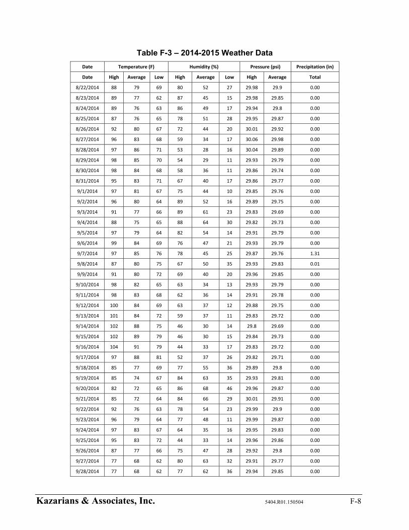
Kazarians & Associates, Inc. 5404.R01.150504 F-8
Table F-3 – 2014-2015 Weather Data
Date Temperature (F) Humidity (%) Pressure (psi) Precipitation (in)
Date High Average Low High Average Low High Average Total
8/22/2014 88 79 69 80 52 27 29.98 29.9 0.00
8/23/2014 89 77 62 87 45 15 29.98 29.85 0.00
8/24/2014 89 76 63 86 49 17 29.94 29.8 0.00
8/25/2014 87 76 65 78 51 28 29.95 29.87 0.00
8/26/2014 92 80 67 72 44 20 30.01 29.92 0.00
8/27/2014 96 83 68 59 34 17 30.06 29.98 0.00
8/28/2014 97 86 71 53 28 16 30.04 29.89 0.00
8/29/2014 98 85 70 54 29 11 29.93 29.79 0.00
8/30/2014 98 84 68 58 36 11 29.86 29.74 0.00
8/31/2014 95 83 71 67 40 17 29.86 29.77 0.00
9/1/2014 97 81 67 75 44 10 29.85 29.76 0.00
9/2/2014 96 80 64 89 52 16 29.89 29.75 0.00
9/3/2014 91 77 66 89 61 23 29.83 29.69 0.00
9/4/2014 88 75 65 88 64 30 29.82 29.73 0.00
9/5/2014 97 79 64 82 54 14 29.91 29.79 0.00
9/6/2014 99 84 69 76 47 21 29.93 29.79 0.00
9/7/2014 97 85 76 78 45 25 29.87 29.76 1.31
9/8/2014 87 80 75 67 50 35 29.93 29.83 0.01
9/9/2014 91 80 72 69 40 20 29.96 29.85 0.00
9/10/2014 98 82 65 63 34 13 29.93 29.79 0.00
9/11/2014 98 83 68 62 36 14 29.91 29.78 0.00
9/12/2014 100 84 69 63 37 12 29.88 29.75 0.00
9/13/2014 101 84 72 59 37 11 29.83 29.72 0.00
9/14/2014 102 88 75 46 30 14 29.8 29.69 0.00
9/15/2014 102 89 79 46 30 15 29.84 29.73 0.00
9/16/2014 104 91 79 44 33 17 29.83 29.72 0.00
9/17/2014 97 88 81 52 37 26 29.82 29.71 0.00
9/18/2014 85 77 69 77 55 36 29.89 29.8 0.00
9/19/2014 85 74 67 84 63 35 29.93 29.81 0.00
9/20/2014 82 72 65 86 68 46 29.96 29.87 0.00
9/21/2014 85 72 64 84 66 29 30.01 29.91 0.00
9/22/2014 92 76 63 78 54 23 29.99 29.9 0.00
9/23/2014 96 79 64 77 48 11 29.99 29.87 0.00
9/24/2014 97 83 67 64 35 16 29.95 29.83 0.00
9/25/2014 95 83 72 44 33 14 29.96 29.86 0.00
9/26/2014 87 77 66 75 47 28 29.92 29.8 0.00
9/27/2014 77 68 62 80 63 32 29.91 29.77 0.00
9/28/2014 77 68 62 77 62 36 29.94 29.85 0.00

Kazarians & Associates, Inc. 5404.R01.150504 F-9
Table F-3 – 2014-2015 Weather Data
Date Temperature (F) Humidity (%) Pressure (psi) Precipitation (in)
Date High Average Low High Average Low High Average Total
9/29/2014 82 71 60 86 59 29 29.95 29.85 0.00
9/30/2014 89 74 60 76 47 18 29.9 29.76 0.00
10/1/2014 90 74 61 67 47 22 29.91 29.75 0.00
10/2/2014 95 81 63 80 29 5 30.02 29.91 0.00
10/3/2014 97 80 60 32 14 3 30.07 29.95 0.00
10/4/2014 99 80 63 36 19 5 30 29.9 0.00
10/5/2014 96 80 63 41 23 8 29.96 29.83 0.00
10/6/2014 96 79 62 48 25 7 29.95 29.83 0.00
10/7/2014 93 79 67 45 28 9 29.95 29.82 0.00
10/8/2014 90 77 64 59 39 15 29.9 29.79 0.00
10/9/2014 82 70 63 87 65 34 29.97 29.89 0.00
10/10/2014 86 73 61 82 58 28 30.01 29.91 0.00
10/11/2014 90 74 60 79 53 21 29.99 29.88 0.00
10/12/2014 87 78 68 76 48 31 29.95 29.83 0.00
10/13/2014 91 74 59 84 51 12 30.01 29.95 0.00
10/14/2014 82 70 59 78 56 35 30.01 29.9 0.00
10/15/2014 78 69 62 89 66 41 30.02 29.92 0.00
10/16/2014 78 67 59 79 61 37 30.03 29.9 0.00
10/17/2014 77 66 57 79 66 40 30.01 29.91 0.00
10/18/2014 78 69 62 81 64 41 29.95 29.82 0.00
10/19/2014 80 68 57 85 65 37 29.94 29.83 0.00
10/20/2014 81 69 60 83 70 44 29.93 29.86 0.00
10/21/2014 81 69 59 90 66 24 29.94 29.83 0.00
10/22/2014 88 70 57 80 54 10 29.99 29.89 0.00
10/23/2014 91 74 59 70 40 8 30.01 29.92 0.00
10/24/2014 93 75 58 62 32 10 30.02 29.92 0.00
10/25/2014 85 73 62 57 37 20 30.06 29.98 0.00
10/26/2014 78 67 55 79 61 35 30.02 29.86 0.00
10/27/2014 79 67 57 80 63 36 29.97 29.86 0.00
10/28/2014 86 69 56 85 57 20 30.03 29.94 0.00
11/16/2014 68 63 52 23 10 6 30.21 30.13 0.00
11/17/2014 74 61 50 28 18 7 30.2 30.08 0.00
11/18/2014 77 61 46 39 23 8 30.2 30.09 0.00
11/19/2014 73 60 47 66 36 11 30.16 30.05 0.00
11/20/2014 67 58 46 86 63 37 30.12 29.97 0.00
11/21/2014 69 60 54 91 71 43 30.06 29.92 0.09
11/22/2014 71 59 47 87 64 30 30.12 30 0.00
11/23/2014 76 65 54 78 32 6 30.19 30.04 0.05

Kazarians & Associates, Inc. 5404.R01.150504 F-10
Table F-3 – 2014-2015 Weather Data
Date Temperature (F) Humidity (%) Pressure (psi) Precipitation (in)
Date High Average Low High Average Low High Average Total
11/24/2014 76 64 50 38 19 10 30.36 30.17 0.00
11/25/2014 79 62 45 44 23 6 30.42 30.27 0.00
11/26/2014 88 66 49 49 27 6 30.29 30.15 0.00
11/27/2014 89 71 50 49 23 6 30.16 30.02 0.00
11/28/2014 82 67 50 51 28 9 30.04 29.89 0.00
11/29/2014 78 61 47 63 41 15 29.95 29.82 0.00
11/30/2014 65 58 51 93 74 56 30.08 29.91 0.04
12/1/2014 68 62 54 95 74 57 30.19 30.03 0.00
12/2/2014 62 58 56 96 85 65 30.05 29.92 1.22
12/3/2014 66 61 58 97 92 82 30.02 29.92 0.62
12/4/2014 69 63 58 97 80 52 30.09 29.94 0.19
12/5/2014 69 60 52 89 71 49 30.14 30.06 0.00
12/6/2014 71 61 54 93 76 50 30.23 30.14 0.00
12/7/2014 77 63 52 87 61 35 30.23 30.09 0.00
12/8/2014 78 63 54 79 57 28 30.13 30.04 0.00
12/9/2014 77 58 51 75 63 27 30.1 30.03 0.00
12/15/2014 64 55 43 87 58 36 30.08 29.98 0.00
12/16/2014 57 53 49 93 80 66 30.05 29.98 0.09
12/17/2014 59 54 50 94 82 63 30.12 29.96 0.53
12/18/2014 62 53 43 94 74 50 30.23 30.11 0.00
12/19/2014 64 52 43 91 74 43 30.24 30.14 0.00
12/20/2014 60 51 44 91 79 63 30.22 30.11 0.00
12/21/2014 67 56 45 95 78 54 30.17 30.05 0.00
12/22/2014 75 60 51 82 63 38 30.07 29.97 0.00
12/27/2014 60 54 43 48 26 17 30.28 30.22 0.00
12/28/2014 60 47 36 64 44 21 30.26 30.09 0.00
12/29/2014 61 47 35 80 57 35 30.12 30 0.00
12/30/2014 53 45 42 79 66 53 29.95 29.86 0.25
12/31/2014 50 44 36 53 34 23 30.01 29.9 0.00
1/1/2015 55 42 30 75 53 30 30.13 30.01 0.00
1/2/2015 57 44 31 77 59 40 30.13 30.01 0.00
1/3/2015 61 47 34 88 66 41 30.25 30.11 0.00
1/4/2015 69 51 36 88 57 24 30.31 30.21 0.00
1/5/2015 77 60 46 65 37 15 30.26 30.14 0.00
1/6/2015 81 64 48 53 34 13 30.2 30.07 0.00
1/7/2015 82 66 51 54 34 15 30.13 30.02 0.00
1/8/2015 69 54 50 70 61 35 30.05 30 0.00
1/9/2015 63 59 54 76 62 48 29.98 29.94 0.00

Kazarians & Associates, Inc. 5404.R01.150504 F-11
Table F-3 – 2014-2015 Weather Data
Date Temperature (F) Humidity (%) Pressure (psi) Precipitation (in)
Date High Average Low High Average Low High Average Total
1/10/2015 65 56 47 87 70 44 30 29.91 0.00
1/11/2015 58 56 54 96 92 84 30.06 29.93 0.29
1/12/2015 65 56 48 98 86 62 30.14 30.02 0.01
1/13/2015 68 59 47 95 51 25 30.08 29.99 0.01
1/14/2015 69 59 50 58 39 23 30.19 30.06 0.00
1/15/2015 72 57 43 71 45 19 30.23 30.12 0.00
1/16/2015 76 59 44 62 41 15 30.18 30.04 0.00
1/17/2015 78 61 48 62 40 17 30.19 30.07 0.00
1/18/2015 77 61 50 65 46 21 30.21 30.1 0.00
1/19/2015 77 60 47 80 55 22 30.14 29.99 0.00
1/20/2015 68 57 48 90 69 43 29.99 29.85 0.00
1/21/2015 72 62 50 95 44 16 30.08 29.9 0.03
1/22/2015 72 64 54 37 19 11 30.23 30.08 0.00
1/23/2015 72 62 45 43 22 9 30.22 30.07 0.00
1/24/2015 76 68 59 33 18 13 30.11 29.98 0.02
1/25/2015 81 66 53 43 28 14 30.04 29.92 0.00
1/26/2015 73 61 56 94 54 26 30.06 29.94 0.22
1/27/2015 71 62 54 96 70 41 30.16 30.06 0.02
1/28/2015 72 62 51 81 55 34 30.14 30.03 0.00
1/29/2015 72 64 59 63 46 34 30.04 29.95 0.00
1/30/2015 65 60 56 85 63 43 29.95 29.78 0.02
1/31/2015 68 60 51 95 65 38 29.94 29.79 0.00
2/1/2015 75 62 50 72 49 25 30.07 29.94 0.00
2/2/2015 81 63 48 71 46 15 30.06 29.94 0.00
2/3/2015 79 63 47 80 49 17 30.05 29.95 0.00
2/4/2015 80 68 49 81 43 20 30.07 29.98 0.00
2/5/2015 85 67 50 77 47 14 30.05 29.9 0.00
2/6/2015 80 65 50 78 44 15 30.1 30.01 0.00
2/7/2015 72 60 49 84 61 28 30.13 30.06 0.00
2/8/2015 78 66 57 89 66 40 30.11 30.01 0.00
2/9/2015 76 64 54 87 61 31 30.11 29.96 0.00
2/10/2015 81 65 50 75 43 18 29.99 29.85 0.00
2/11/2015 60 57 53 48 45 43 29.99 29.95 0.00
2/12/2015 82 71 51 41 22 10 30.11 29.98 0.00
2/13/2015 87 70 52 44 24 9 30.05 29.92 0.00
2/14/2015 84 68 52 53 29 8 30.06 29.91 0.00
2/15/2015 81 66 51 63 38 17 29.98 29.84 0.00
2/16/2015 80 68 49 77 45 19 29.97 29.87 0.00

Kazarians & Associates, Inc. 5404.R01.150504 F-12
Table F-3 – 2014-2015 Weather Data
Date Temperature (F) Humidity (%) Pressure (psi) Precipitation (in)
Date High Average Low High Average Low High Average Total
2/17/2015 77 63 51 95 68 33 30.06 29.97 0.00
2/18/2015 80 64 50 81 55 21 30.11 29.98 0.00
Average 82.1 69.41 58.0 73.46 50.09 25.58 30.02 29.90 N/A
High/Low 104 N/A 30 98 N/A 3 30.42 29.66 N/A
REFERENCES
F-1. Weather History Table. WeatherUnderground. Retrieved February 19, 2015 from http://www.wunderground.com/personal-weather-station / dashboard?ID=MSDSBO#history / s20140218/e20150219/myear
F-2. "Risk Management Programs for Chemical Accidental Release Prevention", Federal EPA,
40 CFR Part 68.

Appendix G – Phast Input/Output Summaries
Tanker Spill 1 ET04‐01
Input Parameters
Vessel: LNG Tanker
Volume Inventory: 10,200 gallons
Scenario Type: Line Rupture
Release Location: Tanker Unloading Area
Pressure: 60 psig
Orifice Diameter: 3 in.
Pipe Diameter: N/A
Pipe Length: 15 ft.
Duration: 30 seconds
Direction: Horizontal
Elevation: 0 ft.
Tank Head: 7.5 ft.
Explosion Method: BST
Obstacle Density: Low
Confined Volume: 88,500 ft3
Results
Release Rate: 2,330.01 lb/min
Phase: Liquid (Two‐Phase Flow)
Pool Radius: 17 ft.
Time to Vaporize: 188 seconds
Dispersion and Flash Fire
1/2 LFL: 1,158 1/2 LFL: 430 1/2 LFL: 477
LFL: 490 LFL: 283 LFL: 384
UFL: 161 UFL: 131 UFL: 168
Cloud Height: 42 Cloud Height: 33 Cloud Height: 30
Vapor Cloud Explosion
Category 1.5/F: Average Conditions: Santa Ana Conditions:
0.5 psi: None 0.5 psi: None 0.5 psi: None
2 psi: None 2 psi: None 2 psi: None
5 psi: None 5 psi: None 5 psi: None
Pool Fire
Category 1.5/F: Average Conditions: Santa Ana Conditions:
2 kW/m2: 220 2 kW/m2: 230 2 kW/m2: 207
5 kW/m2: 148 5 kW/m2: 160 5 kW/m2: 151
10 kW/m2: 110 10 kW/m2: 122 10 kW/m2: 122
Jet Fire
Category 1.5/F: Average Conditions: Santa Ana Conditions:
2 kW/m2: 288 2 kW/m2: 272 2 kW/m2: 251
5 kW/m2: 241 5 kW/m2: 219 5 kW/m2: 197
10 kW/m2: 216 10 kW/m2: 192 10 kW/m2: 169
Event: Hose failure during LNG unloading with the driver activating the emergency shutdown system. It is assumed that this
event is represented by a 3” diameter opening at ground level and for a duration of 30 seconds.
Category 1.5/F: Average Conditions: Santa Ana Conditions:
Kazarians Associates, Inc. 5404.R01.150504 G-1

Tanker Spill 2 ET04‐02
Input Parameters
Vessel: LNG Tanker
Volume Inventory: 10,200 gallons
Scenario Type: Line Rupture
Release Location: Tanker Unloading Area
Pressure: 60 psig
Orifice Diameter: 3 in.
Pipe Diameter: N/A
Pipe Length: 15 ft.
Duration: Time to Empty LNG Tanker
Direction: Horizontal
Elevation: 0 ft.
Tank Head: 7.5 ft.
Explosion Method: BST
Obstacle Density: Low
Confined Volume: 88,500 ft3
Results
Release Rate: 2,330.01 lb/min
Phase: Liquid (Two‐Phase Flow)
Pool Radius: 37 ft.
Time to Vaporize: 1,387 seconds
Dispersion and Flash Fire
1/2 LFL: 1,308 1/2 LFL: 511 1/2 LFL: 555
LFL: 485 LFL: 326 LFL: 439
UFL: 98 UFL: 144 UFL: 185
Cloud Height: 42 Cloud Height: 40 Cloud Height: 47
Vapor Cloud Explosion
Category 1.5/F: Average Conditions: Santa Ana Conditions:
0.5 psi: None 0.5 psi: None 0.5 psi: None
2 psi: None 2 psi: None 2 psi: None
5 psi: None 5 psi: None 5 psi: None
Pool Fire
Category 1.5/F: Average Conditions: Santa Ana Conditions:
2 kW/m2: 472 2 kW/m2: 501 2 kW/m2: 405
5 kW/m2: 318 5 kW/m2: 345 5 kW/m2: 293
10 kW/m2: 236 10 kW/m2: 261 10 kW/m2: 234
Jet Fire
Category 1.5/F: Average Conditions: Santa Ana Conditions:
2 kW/m2: 288 2 kW/m2: 272 2 kW/m2: 251
5 kW/m2: 241 5 kW/m2: 219 5 kW/m2: 197
10 kW/m2: 216 10 kW/m2: 192 10 kW/m2: 169
Event: Hose failure during LNG unloading without activating the emergency shutdown system, which means that the entire
contents of the Tanker will be spilled. It is assumed that this event is represented by a 3” diameter opening at ground level.
Category 1.5/F: Average Conditions: Santa Ana Conditions:
Kazarians Associates, Inc. 5404.R01.150504 G-2

Tanker Spill 3 No Offsite Cons.
Input Parameters
Vessel: LNG Tanker
Volume Inventory: 10,200 gallons
Scenario Type: Line Rupture
Release Location: Tanker Unloading Area
Pressure: 60 psig
Orifice Diameter: 1/4” in.
Pipe Diameter: N/A
Pipe Length: 15 ft.
Duration: 30 Seconds
Direction: Horizontal
Elevation: 0 ft.
Tank Head: 7.5 ft.
Explosion Method: BST
Obstacle Density: Low
Confined Volume: 88,500 ft3
Results
Release Rate: 130.047 lb/min
Phase: Liquid (Two‐Phase Flow)
Pool Radius: 0.5 ft.
Time to Vaporize: 30 seconds
Dispersion and Flash Fire
1/2 LFL: 45 1/2 LFL: 19 1/2 LFL: 10
LFL: 27 LFL: 14 LFL: 7
UFL: 11 UFL: 7 UFL: 3
Cloud Height: 10 Cloud Height: 2 Cloud Height: 0.6
Vapor Cloud Explosion
Category 1.5/F: Average Conditions: Santa Ana Conditions:
0.5 psi: None 0.5 psi: None 0.5 psi: None
2 psi: None 2 psi: None 2 psi: None
5 psi: None 5 psi: None 5 psi: None
Pool Fire
Category 1.5/F: Average Conditions: Santa Ana Conditions:
2 kW/m2: 2 2 kW/m2: 2 2 kW/m2: 2
5 kW/m2: 1 5 kW/m2: 1 5 kW/m2: 1.3
10 kW/m2: 0.5 10 kW/m2: 0.6 10 kW/m2: 0.5
Jet Fire
Category 1.5/F: Average Conditions: Santa Ana Conditions:
2 kW/m2: 22 2 kW/m2: 20 2 kW/m2: 18
5 kW/m2: 19 5 kW/m2: 17 5 kW/m2: 15
10 kW/m2: 17 10 kW/m2: 16 10 kW/m2: 13
Event: Hose leak during LNG unloading with the driver activating the emergency shutdown system. It is assumed that this event
is represented by a 1/4” diameter opening at ground level and for a duration of 30 seconds.
Category 1.5/F: Average Conditions: Santa Ana Conditions:
Kazarians Associates, Inc. 5404.R01.150504 G-3
Tanker Spill 4 No Offsite Cons.
Input Parameters
Vessel: LNG Tanker
Volume Inventory: 10,200 gallons
Scenario Type: Line Rupture
Release Location: Tanker Unloading Area
Pressure: 60 psig
Orifice Diameter: 1/4 in.
Pipe Diameter: N/A
Pipe Length: 15 ft.
Duration: Time to Empty LNG Tanker
Direction: Horizontal
Elevation: 0 ft.
Tank Head: 7.5 ft.
Explosion Method: BST
Obstacle Density: Low
Confined Volume: 88,500 ft3
Results
Release Rate: 7.30031 lb/min
Phase: Liquid (Two‐Phase Flow)
Pool Radius: 0.5 ft.
Time to Vaporize: 1,092 seconds
Dispersion and Flash Fire
1/2 LFL: 46 1/2 LFL: 19 1/2 LFL: 10
LFL: 27 LFL: 14 LFL: 7
UFL: 11 UFL: 7 UFL: 3
Cloud Height: 10 Cloud Height: 2 Cloud Height: 0.6
Vapor Cloud Explosion
Category 1.5/F: Average Conditions: Santa Ana Conditions:
0.5 psi: None 0.5 psi: None 0.5 psi: None
2 psi: None 2 psi: None 2 psi: None
5 psi: None 5 psi: None 5 psi: None
Pool Fire
Category 1.5/F: Average Conditions: Santa Ana Conditions:
2 kW/m2: 5 2 kW/m2: 5 2 kW/m2: 5
5 kW/m2: 4 5 kW/m2: 4 5 kW/m2: 4
10 kW/m2: 2 10 kW/m2: 2 10 kW/m2: 2
Jet Fire
Category 1.5/F: Average Conditions: Santa Ana Conditions:
2 kW/m2: 22 2 kW/m2: 20 2 kW/m2: 18
5 kW/m2: 19 5 kW/m2: 17 5 kW/m2: 15
10 kW/m2: 17 10 kW/m2: 15 10 kW/m2: 13
Event: Spurious PSV lift or hose leak during LNG unloading which spills the entire contents of the Tanker. It is assumed that this
event is represented by a 1/4” diameter opening at ground level.
Category 1.5/F: Average Conditions: Santa Ana Conditions:
Kazarians Associates, Inc. 5404.R01.150504 G-4

Tanker Spill 5 No Offsite Cons.
Input Parameters
Vessel: LNG Tanker
Volume Inventory: 10,200 gallons
Scenario Type: Relief Valve
Release Location: LNG Storage Tank Vault Roof Vent
Pressure: 60 psig
Orifice Diameter: 1/2 in.
Pipe Diameter: 1.5 in.
Pipe Length: 25 ft.
Duration: Time to Empty LNG Tanker
Direction: Vertical
Elevation: 12 ft.
Tank Head: 7.5 ft.
Explosion Method: BST
Obstacle Density: Low
Confined Volume: 1 m3
Results
Release Rate: 75.9454 lb/min
Phase: Liquid (Two‐Phase Flow)
Pool Radius: N/A
Time to Vaporize: N/A
Dispersion and Flash Fire
1/2 LFL: 11 1/2 LFL: 11 1/2 LFL: 11
LFL: 5 LFL: 5 LFL: 5
UFL: 1 UFL: 1 UFL: 1
Cloud Height: 38 Cloud Height: 27 Cloud Height: 19
Vapor Cloud Explosion
Category 1.5/F: Average Conditions: Santa Ana Conditions:
0.5 psi: None 0.5 psi: None 0.5 psi: None
2 psi: None 2 psi: None 2 psi: None
5 psi: None 5 psi: None 5 psi: None
Pool Fire
Category 1.5/F: Average Conditions: Santa Ana Conditions:
2 kW/m2: None 2 kW/m2: None 2 kW/m2: None
5 kW/m2: None 5 kW/m2: None 5 kW/m2: None
10 kW/m2: None 10 kW/m2: None 10 kW/m2: None
Jet Fire
Category 1.5/F: Average Conditions: Santa Ana Conditions:
2 kW/m2: 47 2 kW/m2: 58 2 kW/m2: 61
5 kW/m2: None 5 kW/m2: 36 5 kW/m2: 44
10 kW/m2: None 10 kW/m2: None 10 kW/m2: 33
Event: During filling, the operator leaves AOV‐27 open when the pump pot is full. It is assumed that this event is represented by
a 1/2” diameter opening at ground level and continues until the Tanker is empty.
Category 1.5/F: Average Conditions: Santa Ana Conditions:
Kazarians Associates, Inc. 5404.R01.150504 G-5

Tanker Spill 6 ET02‐11
Input Parameters
Vessel: LNG Tanker
Volume Inventory: 10,200 gallons
Scenario Type: Line Rupture
Release Location: Pump Area of the LNG Storage Vault
Pressure: 60 psig
Orifice Diameter: 3 in.
Pipe Diameter: N/A
Pipe Length: 30 ft.
Duration: 30 Seconds
Direction: Horizontal
Elevation: 0 ft.
Tank Head: 7.5 ft.
Explosion Method: BST
Obstacle Density: Medium
Confined Volume: 46,240 ft3
Results
Release Rate: 1,811.3 lb/min
Phase: Liquid (Two‐Phase Flow)
Pool Radius: N/A
Time to Vaporize: N/A
Dispersion and Flash Fire
1/2 LFL: 208 1/2 LFL: 51 1/2 LFL: 34
LFL: 103 LFL: 25 LFL: 17
UFL: 12 UFL: 6 UFL: 4
Cloud Height: 6 Cloud Height: 3 Cloud Height: 2
Vapor Cloud Explosion
Category 1.5/F: Average Conditions: Santa Ana Conditions:
0.5 psi: None 0.5 psi: None 0.5 psi: None
2 psi: None 2 psi: None 2 psi: None
5 psi: None 5 psi: None 5 psi: None
Pool Fire
Category 1.5/F: Average Conditions: Santa Ana Conditions:
2 kW/m2: None 2 kW/m2: None 2 kW/m2: None
5 kW/m2: None 5 kW/m2: None 5 kW/m2: None
10 kW/m2: None 10 kW/m2: None 10 kW/m2: None
Jet Fire
Category 1.5/F: Average Conditions: Santa Ana Conditions:
2 kW/m2: None 2 kW/m2: None 2 kW/m2: None
5 kW/m2: None 5 kW/m2: None 5 kW/m2: None
10 kW/m2: None 10 kW/m2: None 10 kW/m2: None
Event: 3” Pipe break inside the LNG Storage Vault. The release occurs during the filling operation, and the operator is able to
activate the Tanker shutdown switch. It is assumed that this event is represented by a 3” diameter opening at ground level and
continues for 30 seconds.
Category 1.5/F: Average Conditions: Santa Ana Conditions:
Kazarians Associates, Inc. 5404.R01.150504 G-6
Tanker Spill 7 ET02‐12
Input Parameters
Vessel: LNG Tanker
Volume Inventory: 10,200 gallons
Scenario Type: Line Rupture
Release Location: Pump Area of the LNG Storage Vault (Modelled as outdoors due to large release rate)
Pressure: 60 psig
Orifice Diameter: 3 in.
Pipe Diameter: N/A
Pipe Length: 30 ft.
Duration: Time to Empty LNG Tanker
Direction: Horizontal
Elevation: 0 ft.
Tank Head: 7.5 ft.
Explosion Method: BST
Obstacle Density: Medium
Confined Volume: 46,240 ft3
Results
Release Rate: 1,811.3 lb/min
Phase: Liquid (Two‐Phase Flow)
Pool Radius: 16
Time to Vaporize: > 7,200 seconds
Dispersion and Flash Fire
1/2 LFL: 1,015 1/2 LFL: 383 1/2 LFL: 443
LFL: 408 LFL: 255 LFL: 354
UFL: 84 UFL: 117 UFL: 153
Cloud Height: 42 Cloud Height: 30 Cloud Height: 38
Vapor Cloud Explosion
Category 1.5/F: Average Conditions: Santa Ana Conditions:
0.5 psi: None 0.5 psi: None 0.5 psi: None
2 psi: None 2 psi: None 2 psi: None
5 psi: None 5 psi: None 5 psi: None
Pool Fire
Category 1.5/F: Average Conditions: Santa Ana Conditions:
2 kW/m2: 199 2 kW/m2: 206 2 kW/m2: 191
5 kW/m2: 135 5 kW/m2: 143 5 kW/m2: 140
10 kW/m2: 100 10 kW/m2: 108 10 kW/m2: 113
Jet Fire
Category 1.5/F: Average Conditions: Santa Ana Conditions:
2 kW/m2: None 2 kW/m2: None 2 kW/m2: None
5 kW/m2: None 5 kW/m2: None 5 kW/m2: None
10 kW/m2: None 10 kW/m2: None 10 kW/m2: None
Event: 3” Pipe break inside the LNG Storage Vault. The release occurs during the filling operation, and the driver is unable to
activate the shutdown switch. It is assumed that this event is represented by a 3” diameter opening at ground level and
continues until the Tanker empties.
Category 1.5/F: Average Conditions: Santa Ana Conditions:
Kazarians Associates, Inc. 5404.R01.150504 G-7

Tanker Spill 8 ET01‐06
Input Parameters
Vessel: LNG Tanker
Volume Inventory: 7,000 gallons
Scenario Type: Line Rupture
Release Location: LNG Storage Tank Vault Roof Vent
Pressure: 175 psig
Orifice Diameter: 3/4 in.
Pipe Diameter: N/A
Pipe Length: 25 ft.
Duration: Time to Empty LNG Tanker
Direction: Vertical
Elevation: 12 ft.
Tank Head: 0 ft.
Explosion Method: BST
Obstacle Density: Low
Confined Volume: 1 m3
Results
Release Rate: 138.724 lb/min
Phase: Liquid (Two‐Phase Flow)
Pool Radius: N/A
Time to Vaporize: N/A
Dispersion and Flash Fire
1/2 LFL: 7 1/2 LFL: 7 1/2 LFL: 8
LFL: 3 LFL: 3 LFL: 4
UFL: 0.7 UFL: 0.7 UFL: 1
Cloud Height: 46 Cloud Height: 34 Cloud Height: 23
Vapor Cloud Explosion
Category 1.5/F: Average Conditions: Santa Ana Conditions:
0.5 psi: None 0.5 psi: None 0.5 psi: None
2 psi: None 2 psi: None 2 psi: None
5 psi: None 5 psi: None 5 psi: None
Pool Fire
Category 1.5/F: Average Conditions: Santa Ana Conditions:
2 kW/m2: None 2 kW/m2: None 2 kW/m2: None
5 kW/m2: None 5 kW/m2: None 5 kW/m2: None
10 kW/m2: None 10 kW/m2: None 10 kW/m2: None
Jet Fire
Category 1.5/F: Average Conditions: Santa Ana Conditions:
2 kW/m2: 51 2 kW/m2: 65 2 kW/m2: 71
5 kW/m2: None 5 kW/m2: 33 5 kW/m2: 50
10 kW/m2: None 10 kW/m2: None 10 kW/m2: 37
Event: During Filling, a Storage Tank is overfilled, causing a PSV to lift to the roof vent. It is assumed that this event is
represented by a 3/4” diameter opening at 12 ft. elevation. Additionally, it is assumed that the Storage Tank has excess capacity
of 3,000 gallons, causing the remaining 7,000 in the truck to be vented to the roof.
Category 1.5/F: Average Conditions: Santa Ana Conditions:
Kazarians Associates, Inc. 5404.R01.150504 G-8
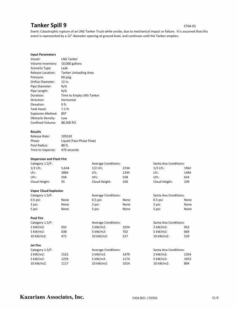
Tanker Spill 9 ET04‐03
Input Parameters
Vessel: LNG Tanker
Volume Inventory: 10,000 gallons
Scenario Type: Leak
Release Location: Tanker Unloading Area
Pressure: 60 psig
Orifice Diameter: 12 in.
Pipe Diameter: N/A
Pipe Length: N/A
Duration: Time to Empty LNG Tanker
Direction: Horizontal
Elevation: 0 ft.
Tank Head: 7.5 ft.
Explosion Method: BST
Obstacle Density: Low
Confined Volume: 88,500 ft3
Results
Release Rate: 105520
Phase: Liquid (Two‐Phase Flow)
Pool Radius: 88 ft.
Time to Vaporize: 470 seconds
Dispersion and Flash Fire
1/2 LFL: 5,634 1/2 LFL: 2234 1/2 LFL: 1962
LFL: 2884 LFL: 1345 LFL: 1484
UFL: 558 UFL: 558 UFL: 634
Cloud Height: 55 Cloud Height: 100 Cloud Height: 109
Vapor Cloud Explosion
Category 1.5/F: Average Conditions: Santa Ana Conditions:
0.5 psi: None 0.5 psi: None 0.5 psi: None
2 psi: None 2 psi: None 2 psi: None
5 psi: None 5 psi: None 5 psi: None
Pool Fire
Category 1.5/F: Average Conditions: Santa Ana Conditions:
2 kW/m2: 932 2 kW/m2: 1024 2 kW/m2: 933
5 kW/m2: 638 5 kW/m2: 702 5 kW/m2: 669
10 kW/m2: 472 10 kW/m2: 527 10 kW/m2: 529
Jet Fire
Category 1.5/F: Average Conditions: Santa Ana Conditions:
2 kW/m2: 1522 2 kW/m2: 1479 2 kW/m2: 1354
5 kW/m2: 1259 5 kW/m2: 1174 5 kW/m2: 1053
10 kW/m2: 1117 10 kW/m2: 1014 10 kW/m2: 894
Event: Catastrophic rupture of an LNG Tanker Truck while onsite, due to mechanical impact or failure. It is assumed that this
event is represented by a 12" diameter opening at ground level, and continues until the Tanker empties.
Category 1.5/F: Average Conditions: Santa Ana Conditions:
Kazarians Associates, Inc. 5404.R01.150504 G-9
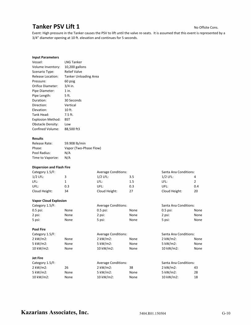
Tanker PSV Lift 1 No Offsite Cons.
Input Parameters
Vessel: LNG Tanker
Volume Inventory: 10,200 gallons
Scenario Type: Relief Valve
Release Location: Tanker Unloading Area
Pressure: 60 psig
Orifice Diameter: 3/4 in.
Pipe Diameter: 1 in.
Pipe Length: 5 ft.
Duration: 30 Seconds
Direction: Vertical
Elevation: 10 ft.
Tank Head: 7.5 ft.
Explosion Method: BST
Obstacle Density: Low
Confined Volume: 88,500 ft3
Results
Release Rate: 59.908 lb/min
Phase: Vapor (Two‐Phase Flow)
Pool Radius: N/A
Time to Vaporize: N/A
Dispersion and Flash Fire
1/2 LFL: 3 1/2 LFL: 3.5 1/2 LFL: 4
LFL: 1 LFL: 1.5 LFL: 2
UFL: 0.3 UFL: 0.3 UFL: 0.4
Cloud Height: 34 Cloud Height: 27 Cloud Height: 20
Vapor Cloud Explosion
Category 1.5/F: Average Conditions: Santa Ana Conditions:
0.5 psi: None 0.5 psi: None 0.5 psi: None
2 psi: None 2 psi: None 2 psi: None
5 psi: None 5 psi: None 5 psi: None
Pool Fire
Category 1.5/F: Average Conditions: Santa Ana Conditions:
2 kW/m2: None 2 kW/m2: None 2 kW/m2: None
5 kW/m2: None 5 kW/m2: None 5 kW/m2: None
10 kW/m2: None 10 kW/m2: None 10 kW/m2: None
Jet Fire
Category 1.5/F: Average Conditions: Santa Ana Conditions:
2 kW/m2: 26 2 kW/m2: 38 2 kW/m2: 43
5 kW/m2: None 5 kW/m2: None 5 kW/m2: 28
10 kW/m2: None 10 kW/m2: None 10 kW/m2: 18
Event: High pressure in the Tanker causes the PSV to lift until the valve re‐seats. It is assumed that this event is represented by a
3/4” diameter opening at 10 ft. elevation and continues for 5 seconds.
Category 1.5/F: Average Conditions: Santa Ana Conditions:
Kazarians Associates, Inc. 5404.R01.150504 G-10
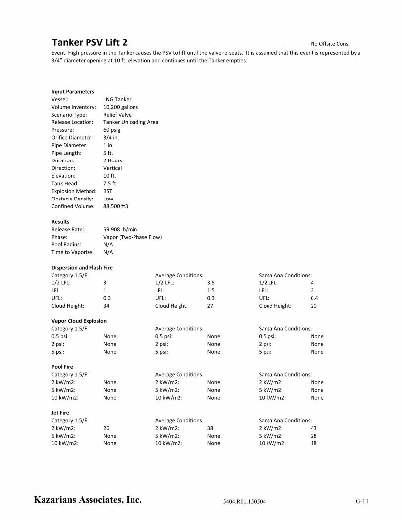
Tanker PSV Lift 2 No Offsite Cons.
Input Parameters
Vessel: LNG Tanker
Volume Inventory: 10,200 gallons
Scenario Type: Relief Valve
Release Location: Tanker Unloading Area
Pressure: 60 psig
Orifice Diameter: 3/4 in.
Pipe Diameter: 1 in.
Pipe Length: 5 ft.
Duration: 2 Hours
Direction: Vertical
Elevation: 10 ft.
Tank Head: 7.5 ft.
Explosion Method: BST
Obstacle Density: Low
Confined Volume: 88,500 ft3
Results
Release Rate: 59.908 lb/min
Phase: Vapor (Two‐Phase Flow)
Pool Radius: N/A
Time to Vaporize: N/A
Dispersion and Flash Fire
1/2 LFL: 3 1/2 LFL: 3.5 1/2 LFL: 4
LFL: 1 LFL: 1.5 LFL: 2
UFL: 0.3 UFL: 0.3 UFL: 0.4
Cloud Height: 34 Cloud Height: 27 Cloud Height: 20
Vapor Cloud Explosion
Category 1.5/F: Average Conditions: Santa Ana Conditions:
0.5 psi: None 0.5 psi: None 0.5 psi: None
2 psi: None 2 psi: None 2 psi: None
5 psi: None 5 psi: None 5 psi: None
Pool Fire
Category 1.5/F: Average Conditions: Santa Ana Conditions:
2 kW/m2: None 2 kW/m2: None 2 kW/m2: None
5 kW/m2: None 5 kW/m2: None 5 kW/m2: None
10 kW/m2: None 10 kW/m2: None 10 kW/m2: None
Jet Fire
Category 1.5/F: Average Conditions: Santa Ana Conditions:
2 kW/m2: 26 2 kW/m2: 38 2 kW/m2: 43
5 kW/m2: None 5 kW/m2: None 5 kW/m2: 28
10 kW/m2: None 10 kW/m2: None 10 kW/m2: 18
Event: High pressure in the Tanker causes the PSV to lift until the valve re‐seats. It is assumed that this event is represented by a
3/4” diameter opening at 10 ft. elevation and continues until the Tanker empties.
Category 1.5/F: Average Conditions: Santa Ana Conditions:
Kazarians Associates, Inc. 5404.R01.150504 G-11

LP Liquid Venting 1 No Offsite Cons.
Input Parameters
Vessel: 3” x 10’ Piping Segment
Volume Inventory: 0.49 ft3
Scenario Type: Relief Valve
Release Location: LNG Storage Tank Vault Roof Vent
Pressure: 200 psig
Orifice Diameter: 1/4 in.
Pipe Diameter: 1.5 in.
Pipe Length: 25 ft.
Duration: 5 Seconds
Direction: Vertical
Elevation: 12 ft.
Tank Head: 0 ft.
Explosion Method: BST
Obstacle Density: Low
Confined Volume: 1 m3
Results
Release Rate: 41.1204 lb/min
Phase: Liquid (Two‐Phase Flow)
Pool Radius: N/A
Time to Vaporize: N/A
Dispersion and Flash Fire
1/2 LFL: 9 1/2 LFL: 10 1/2 LFL: 9
LFL: 4 LFL: 4 LFL: 5
UFL: 1 UFL: 1 UFL: 1
Cloud Height: 31 Cloud Height: 23 Cloud Height: 17
Vapor Cloud Explosion
Category 1.5/F: Average Conditions: Santa Ana Conditions:
0.5 psi: None 0.5 psi: None 0.5 psi: None
2 psi: None 2 psi: None 2 psi: None
5 psi: None 5 psi: None 5 psi: None
Pool Fire
Category 1.5/F: Average Conditions: Santa Ana Conditions:
2 kW/m2: None 2 kW/m2: None 2 kW/m2: None
5 kW/m2: None 5 kW/m2: None 5 kW/m2: None
10 kW/m2: None 10 kW/m2: None 10 kW/m2: None
Jet Fire
Category 1.5/F: Average Conditions: Santa Ana Conditions:
2 kW/m2: 33 2 kW/m2: 43 2 kW/m2: 46
5 kW/m2: None 5 kW/m2: 25 5 kW/m2: 33
10 kW/m2: None 10 kW/m2: None 10 kW/m2: 24
Event: Thermal expansion of a blocked in segment of 3” piping causes the thermal PSV to lift to the roof vent and re‐seat. It is
assumed that this event is represented by a 1/4” diameter opening at 12 ft. elevation and continues for 5 seconds.
Category 1.5/F: Average Conditions: Santa Ana Conditions:
Kazarians Associates, Inc. 5404.R01.150504 G-12
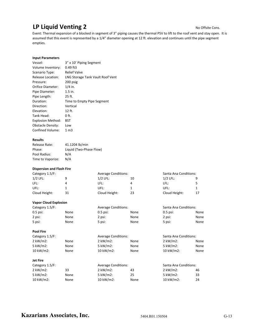
LP Liquid Venting 2 No Offsite Cons.
Input Parameters
Vessel: 3” x 10’ Piping Segment
Volume Inventory: 0.49 ft3
Scenario Type: Relief Valve
Release Location: LNG Storage Tank Vault Roof Vent
Pressure: 200 psig
Orifice Diameter: 1/4 in.
Pipe Diameter: 1.5 in.
Pipe Length: 25 ft.
Duration: Time to Empty Pipe Segment
Direction: Vertical
Elevation: 12 ft.
Tank Head: 0 ft.
Explosion Method: BST
Obstacle Density: Low
Confined Volume: 1 m3
Results
Release Rate: 41.1204 lb/min
Phase: Liquid (Two‐Phase Flow)
Pool Radius: N/A
Time to Vaporize: N/A
Dispersion and Flash Fire
1/2 LFL: 9 1/2 LFL: 10 1/2 LFL: 9
LFL: 4 LFL: 4 LFL: 5
UFL: 1 UFL: 1 UFL: 1
Cloud Height: 31 Cloud Height: 23 Cloud Height: 17
Vapor Cloud Explosion
Category 1.5/F: Average Conditions: Santa Ana Conditions:
0.5 psi: None 0.5 psi: None 0.5 psi: None
2 psi: None 2 psi: None 2 psi: None
5 psi: None 5 psi: None 5 psi: None
Pool Fire
Category 1.5/F: Average Conditions: Santa Ana Conditions:
2 kW/m2: None 2 kW/m2: None 2 kW/m2: None
5 kW/m2: None 5 kW/m2: None 5 kW/m2: None
10 kW/m2: None 10 kW/m2: None 10 kW/m2: None
Jet Fire
Category 1.5/F: Average Conditions: Santa Ana Conditions:
2 kW/m2: 33 2 kW/m2: 43 2 kW/m2: 46
5 kW/m2: None 5 kW/m2: 25 5 kW/m2: 33
10 kW/m2: None 10 kW/m2: None 10 kW/m2: 24
Event: Thermal expansion of a blocked in segment of 3” piping causes the thermal PSV to lift to the roof vent and stay open. It is
assumed that this event is represented by a 1/4” diameter opening at 12 ft. elevation and continues until the pipe segment
empties.
Category 1.5/F: Average Conditions: Santa Ana Conditions:
Kazarians Associates, Inc. 5404.R01.150504 G-13

LP Liquid Venting 3 ET01‐07
Input Parameters
Vessel: LNG Tanker Truck
Volume Inventory: 10,200 gallons
Scenario Type: Relief Valve
Release Location: LNG Storage Tank Vault Roof Vent
Pressure: 60 psig
Orifice Diameter: 1/2 in.
Pipe Diameter: 1.5 in.
Pipe Length: 25 ft.
Duration: 30 Seconds
Direction: Vertical
Elevation: 12 ft.
Tank Head: 7.5 ft.
Explosion Method: BST
Obstacle Density: Low
Confined Volume: 1 m3
Results
Release Rate: 75.9454 lb/min
Phase: Liquid (Two‐Phase Flow)
Pool Radius: N/A
Time to Vaporize: N/A
Dispersion and Flash Fire
1/2 LFL: 11 1/2 LFL: 11 1/2 LFL: 11
LFL: 5 LFL: 5 LFL: 5
UFL: 1 UFL: 1 UFL: 1
Cloud Height: 38 Cloud Height: 27 Cloud Height: 19
Vapor Cloud Explosion
Category 1.5/F: Average Conditions: Santa Ana Conditions:
0.5 psi: None 0.5 psi: None 0.5 psi: None
2 psi: None 2 psi: None 2 psi: None
5 psi: None 5 psi: None 5 psi: None
Pool Fire
Category 1.5/F: Average Conditions: Santa Ana Conditions:
2 kW/m2: None 2 kW/m2: None 2 kW/m2: None
5 kW/m2: None 5 kW/m2: None 5 kW/m2: None
10 kW/m2: None 10 kW/m2: None 10 kW/m2: None
Jet Fire
Category 1.5/F: Average Conditions: Santa Ana Conditions:
2 kW/m2: 47 2 kW/m2: 58 2 kW/m2: 61
5 kW/m2: None 5 kW/m2: 36 5 kW/m2: 44
10 kW/m2: None 10 kW/m2: None 10 kW/m2: 33
Event: Venting liquid to the roof vent through AOV‐27 during normal filling operation. It is assumed that this event is
represented by a 1/2” diameter opening at 12 ft. elevation and continues for 30 seconds.
Category 1.5/F: Average Conditions: Santa Ana Conditions:
Kazarians Associates, Inc. 5404.R01.150504 G-14
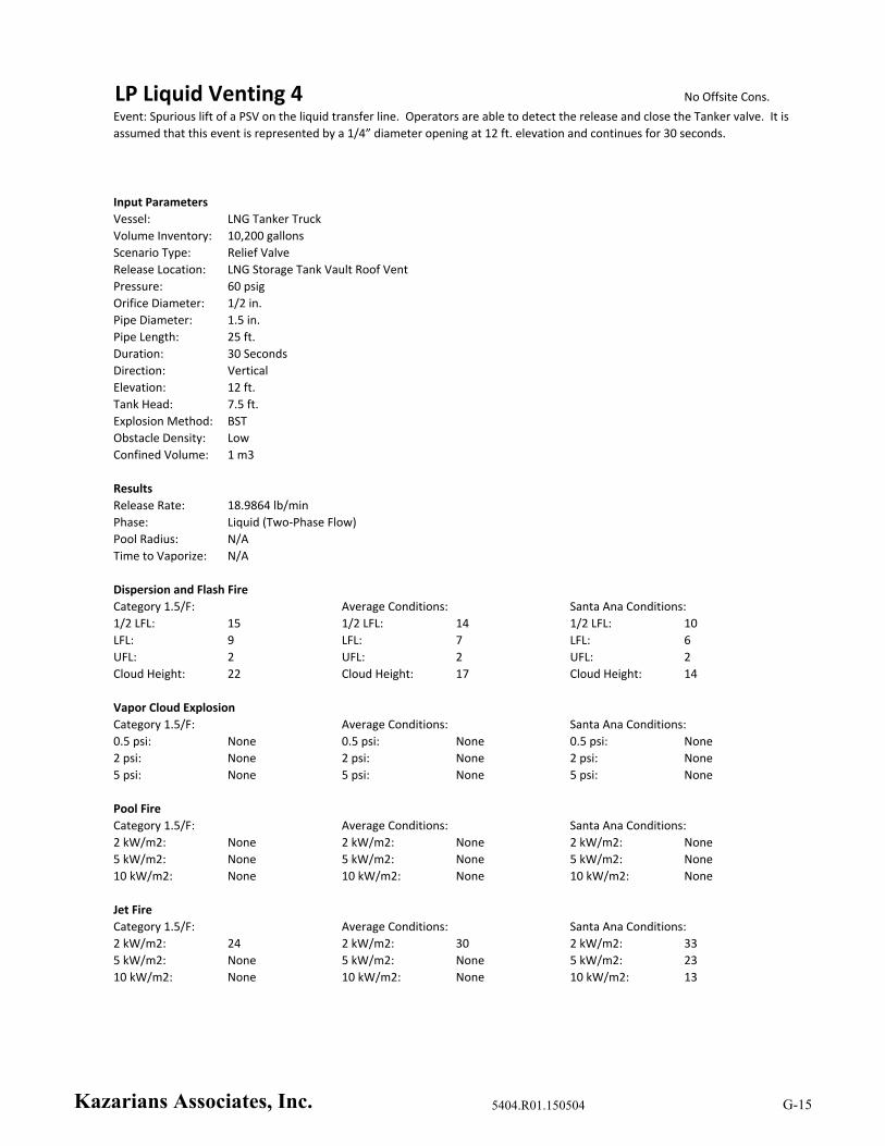
LP Liquid Venting 4 No Offsite Cons.
Input Parameters
Vessel: LNG Tanker Truck
Volume Inventory: 10,200 gallons
Scenario Type: Relief Valve
Release Location: LNG Storage Tank Vault Roof Vent
Pressure: 60 psig
Orifice Diameter: 1/2 in.
Pipe Diameter: 1.5 in.
Pipe Length: 25 ft.
Duration: 30 Seconds
Direction: Vertical
Elevation: 12 ft.
Tank Head: 7.5 ft.
Explosion Method: BST
Obstacle Density: Low
Confined Volume: 1 m3
Results
Release Rate: 18.9864 lb/min
Phase: Liquid (Two‐Phase Flow)
Pool Radius: N/A
Time to Vaporize: N/A
Dispersion and Flash Fire
1/2 LFL: 15 1/2 LFL: 14 1/2 LFL: 10
LFL: 9 LFL: 7 LFL: 6
UFL: 2 UFL: 2 UFL: 2
Cloud Height: 22 Cloud Height: 17 Cloud Height: 14
Vapor Cloud Explosion
Category 1.5/F: Average Conditions: Santa Ana Conditions:
0.5 psi: None 0.5 psi: None 0.5 psi: None
2 psi: None 2 psi: None 2 psi: None
5 psi: None 5 psi: None 5 psi: None
Pool Fire
Category 1.5/F: Average Conditions: Santa Ana Conditions:
2 kW/m2: None 2 kW/m2: None 2 kW/m2: None
5 kW/m2: None 5 kW/m2: None 5 kW/m2: None
10 kW/m2: None 10 kW/m2: None 10 kW/m2: None
Jet Fire
Category 1.5/F: Average Conditions: Santa Ana Conditions:
2 kW/m2: 24 2 kW/m2: 30 2 kW/m2: 33
5 kW/m2: None 5 kW/m2: None 5 kW/m2: 23
10 kW/m2: None 10 kW/m2: None 10 kW/m2: 13
Event: Spurious lift of a PSV on the liquid transfer line. Operators are able to detect the release and close the Tanker valve. It is
assumed that this event is represented by a 1/4” diameter opening at 12 ft. elevation and continues for 30 seconds.
Category 1.5/F: Average Conditions: Santa Ana Conditions:
Kazarians Associates, Inc. 5404.R01.150504 G-15
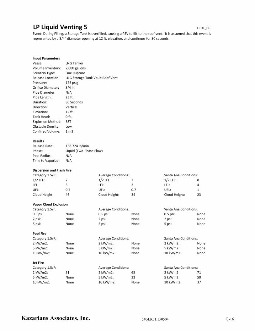
LP Liquid Venting 5 ET01_06
Input Parameters
Vessel: LNG Tanker
Volume Inventory: 7,000 gallons
Scenario Type: Line Rupture
Release Location: LNG Storage Tank Vault Roof Vent
Pressure: 175 psig
Orifice Diameter: 3/4 in.
Pipe Diameter: N/A
Pipe Length: 25 ft.
Duration: 30 Seconds
Direction: Vertical
Elevation: 12 ft.
Tank Head: 0 ft.
Explosion Method: BST
Obstacle Density: Low
Confined Volume: 1 m3
Results
Release Rate: 138.724 lb/min
Phase: Liquid (Two‐Phase Flow)
Pool Radius: N/A
Time to Vaporize: N/A
Dispersion and Flash Fire
1/2 LFL: 7 1/2 LFL: 7 1/2 LFL: 8
LFL: 3 LFL: 3 LFL: 4
UFL: 0.7 UFL: 0.7 UFL: 1
Cloud Height: 46 Cloud Height: 34 Cloud Height: 23
Vapor Cloud Explosion
Category 1.5/F: Average Conditions: Santa Ana Conditions:
0.5 psi: None 0.5 psi: None 0.5 psi: None
2 psi: None 2 psi: None 2 psi: None
5 psi: None 5 psi: None 5 psi: None
Pool Fire
Category 1.5/F: Average Conditions: Santa Ana Conditions:
2 kW/m2: None 2 kW/m2: None 2 kW/m2: None
5 kW/m2: None 5 kW/m2: None 5 kW/m2: None
10 kW/m2: None 10 kW/m2: None 10 kW/m2: None
Jet Fire
Category 1.5/F: Average Conditions: Santa Ana Conditions:
2 kW/m2: 51 2 kW/m2: 65 2 kW/m2: 71
5 kW/m2: None 5 kW/m2: 33 5 kW/m2: 50
10 kW/m2: None 10 kW/m2: None 10 kW/m2: 37
Event: During Filling, a Storage Tank is overfilled, causing a PSV to lift to the roof vent. It is assumed that this event is
represented by a 3/4” diameter opening at 12 ft. elevation, and continues for 30 seconds.
Category 1.5/F: Average Conditions: Santa Ana Conditions:
Kazarians Associates, Inc. 5404.R01.150504 G-16

LP Liquid Venting 6 No Offsite Cons.
Input Parameters
Vessel: LNG Storage Tank
Volume Inventory: 30,000 gallons
Scenario Type: Line Rupture
Release Location: LNG Storage Tank Vault Roof Vent
Pressure: 120 psig
Orifice Diameter: 1/4 in.
Pipe Diameter: N/A
Pipe Length: 40 ft.
Duration: 30 Seconds
Direction: Vertical
Elevation: 12 ft.
Tank Head: 10 ft.
Explosion Method: BST
Obstacle Density: Low
Confined Volume: 1 m3
Results
Release Rate: 6.23889 lb/min
Phase: Liquid (Two‐Phase Flow)
Pool Radius: N/A
Time to Vaporize: N/A
Dispersion and Flash Fire
1/2 LFL: 2 1/2 LFL: 2 1/2 LFL: 2
LFL: 0.8 LFL: 0.9 LFL: 1
UFL: 0.2 UFL: 0.2 UFL: 0.3
Cloud Height: 21 Cloud Height: 17 Cloud Height: 15
Vapor Cloud Explosion
Category 1.5/F: Average Conditions: Santa Ana Conditions:
0.5 psi: None 0.5 psi: None 0.5 psi: None
2 psi: None 2 psi: None 2 psi: None
5 psi: None 5 psi: None 5 psi: None
Pool Fire
Category 1.5/F: Average Conditions: Santa Ana Conditions:
2 kW/m2: None 2 kW/m2: None 2 kW/m2: None
5 kW/m2: None 5 kW/m2: None 5 kW/m2: None
10 kW/m2: None 10 kW/m2: None 10 kW/m2: None
Jet Fire
Category 1.5/F: Average Conditions: Santa Ana Conditions:
2 kW/m2: None 2 kW/m2: None 2 kW/m2: 12
5 kW/m2: None 5 kW/m2: None 5 kW/m2: None
10 kW/m2: None 10 kW/m2: None 10 kW/m2: None
Event: A drain valve upstream of the high pressure pumps is left open before starting the system. It is assumed that this event is
represented by a 1/4” diameter opening at 12 ft. elevation, and continues for 30 seconds.
Category 1.5/F: Average Conditions: Santa Ana Conditions:
Kazarians Associates, Inc. 5404.R01.150504 G-17

LP Liquid Spill 1 No Offsite Cons.
Input Parameters
Vessel: LNG Tanker
Volume Inventory: 10,200 gallons
Scenario Type: Line Rupture
Release Location: Pump Area of the LNG Storage Vault
Pressure: 60 psig
Orifice Diameter: 1/4 in.
Pipe Diameter: N/A
Pipe Length: 25 ft.
Duration: Time to Empty LNG Tanker
Direction: Horizontal
Elevation: 0 ft.
Tank Head: 7.5 ft.
Explosion Method: BST
Obstacle Density: Medium
Confined Volume: 46,240 ft3
Results
Release Rate: 5.45688 lb/min
Phase: Liquid (Two‐Phase Flow)
Pool Radius: N/A
Time to Vaporize: N/A
Dispersion and Flash Fire
1/2 LFL: 3 1/2 LFL: 0.7 1/2 LFL: 0.4
LFL: None LFL: None LFL: None
UFL: None UFL: None UFL: None
Cloud Height: 4 Cloud Height: 2 Cloud Height: 2
Vapor Cloud Explosion
Category 1.5/F: Average Conditions: Santa Ana Conditions:
0.5 psi: None 0.5 psi: None 0.5 psi: None
2 psi: None 2 psi: None 2 psi: None
5 psi: None 5 psi: None 5 psi: None
Pool Fire
Category 1.5/F: Average Conditions: Santa Ana Conditions:
2 kW/m2: None 2 kW/m2: None 2 kW/m2: None
5 kW/m2: None 5 kW/m2: None 5 kW/m2: None
10 kW/m2: None 10 kW/m2: None 10 kW/m2: None
Jet Fire
Category 1.5/F: Average Conditions: Santa Ana Conditions:
2 kW/m2: None 2 kW/m2: None 2 kW/m2: None
5 kW/m2: None 5 kW/m2: None 5 kW/m2: None
10 kW/m2: None 10 kW/m2: None 10 kW/m2: None
Event: 1/4” Pipe break inside the LNG Storage Vault. The release occurs during the filling operation. It is assumed that this event
is represented by a 1/4” diameter opening at ground level and continues until the Tanker empties.
Category 1.5/F: Average Conditions: Santa Ana Conditions:
Kazarians Associates, Inc. 5404.R01.150504 G-18
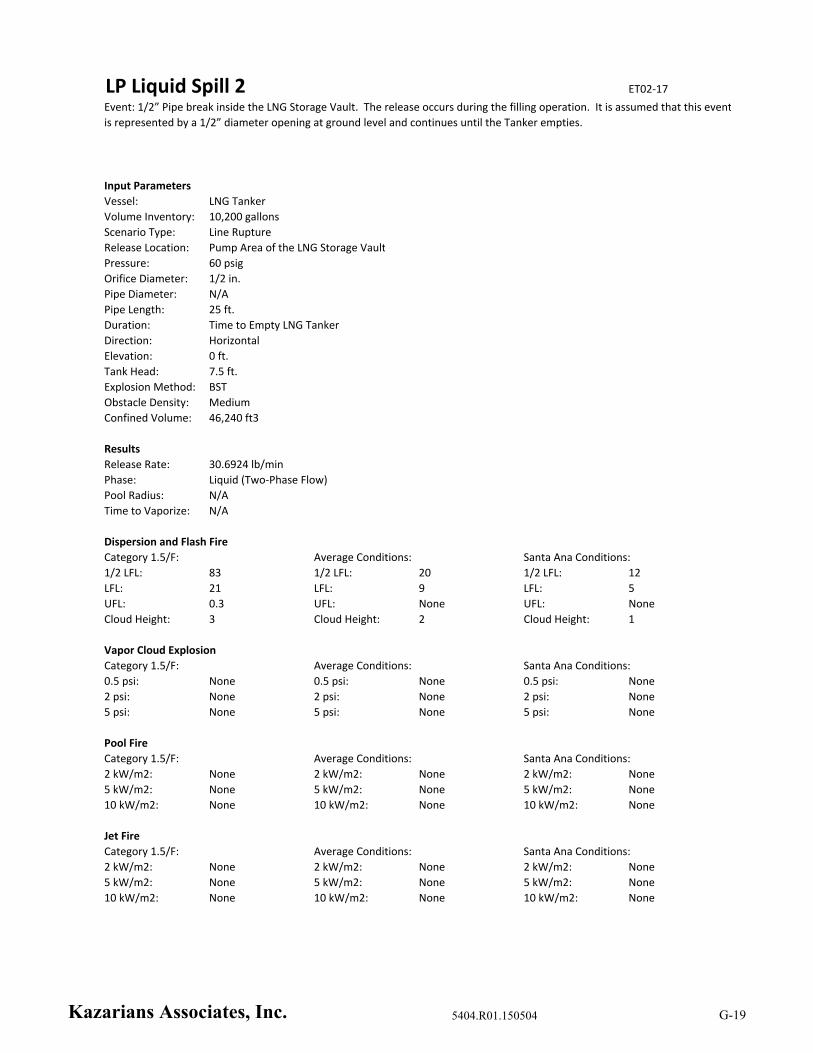
LP Liquid Spill 2 ET02‐17
Input Parameters
Vessel: LNG Tanker
Volume Inventory: 10,200 gallons
Scenario Type: Line Rupture
Release Location: Pump Area of the LNG Storage Vault
Pressure: 60 psig
Orifice Diameter: 1/2 in.
Pipe Diameter: N/A
Pipe Length: 25 ft.
Duration: Time to Empty LNG Tanker
Direction: Horizontal
Elevation: 0 ft.
Tank Head: 7.5 ft.
Explosion Method: BST
Obstacle Density: Medium
Confined Volume: 46,240 ft3
Results
Release Rate: 30.6924 lb/min
Phase: Liquid (Two‐Phase Flow)
Pool Radius: N/A
Time to Vaporize: N/A
Dispersion and Flash Fire
1/2 LFL: 83 1/2 LFL: 20 1/2 LFL: 12
LFL: 21 LFL: 9 LFL: 5
UFL: 0.3 UFL: None UFL: None
Cloud Height: 3 Cloud Height: 2 Cloud Height: 1
Vapor Cloud Explosion
Category 1.5/F: Average Conditions: Santa Ana Conditions:
0.5 psi: None 0.5 psi: None 0.5 psi: None
2 psi: None 2 psi: None 2 psi: None
5 psi: None 5 psi: None 5 psi: None
Pool Fire
Category 1.5/F: Average Conditions: Santa Ana Conditions:
2 kW/m2: None 2 kW/m2: None 2 kW/m2: None
5 kW/m2: None 5 kW/m2: None 5 kW/m2: None
10 kW/m2: None 10 kW/m2: None 10 kW/m2: None
Jet Fire
Category 1.5/F: Average Conditions: Santa Ana Conditions:
2 kW/m2: None 2 kW/m2: None 2 kW/m2: None
5 kW/m2: None 5 kW/m2: None 5 kW/m2: None
10 kW/m2: None 10 kW/m2: None 10 kW/m2: None
Event: 1/2” Pipe break inside the LNG Storage Vault. The release occurs during the filling operation. It is assumed that this event
is represented by a 1/2” diameter opening at ground level and continues until the Tanker empties.
Category 1.5/F: Average Conditions: Santa Ana Conditions:
Kazarians Associates, Inc. 5404.R01.150504 G-19
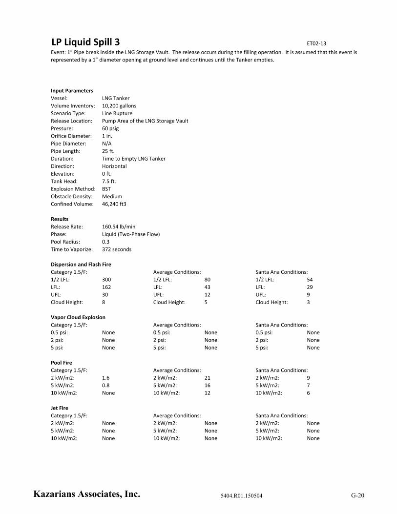
LP Liquid Spill 3 ET02‐13
Input Parameters
Vessel: LNG Tanker
Volume Inventory: 10,200 gallons
Scenario Type: Line Rupture
Release Location: Pump Area of the LNG Storage Vault
Pressure: 60 psig
Orifice Diameter: 1 in.
Pipe Diameter: N/A
Pipe Length: 25 ft.
Duration: Time to Empty LNG Tanker
Direction: Horizontal
Elevation: 0 ft.
Tank Head: 7.5 ft.
Explosion Method: BST
Obstacle Density: Medium
Confined Volume: 46,240 ft3
Results
Release Rate: 160.54 lb/min
Phase: Liquid (Two‐Phase Flow)
Pool Radius: 0.3
Time to Vaporize: 372 seconds
Dispersion and Flash Fire
1/2 LFL: 300 1/2 LFL: 80 1/2 LFL: 54
LFL: 162 LFL: 43 LFL: 29
UFL: 30 UFL: 12 UFL: 9
Cloud Height: 8 Cloud Height: 5 Cloud Height: 3
Vapor Cloud Explosion
Category 1.5/F: Average Conditions: Santa Ana Conditions:
0.5 psi: None 0.5 psi: None 0.5 psi: None
2 psi: None 2 psi: None 2 psi: None
5 psi: None 5 psi: None 5 psi: None
Pool Fire
Category 1.5/F: Average Conditions: Santa Ana Conditions:
2 kW/m2: 1.6 2 kW/m2: 21 2 kW/m2: 9
5 kW/m2: 0.8 5 kW/m2: 16 5 kW/m2: 7
10 kW/m2: None 10 kW/m2: 12 10 kW/m2: 6
Jet Fire
Category 1.5/F: Average Conditions: Santa Ana Conditions:
2 kW/m2: None 2 kW/m2: None 2 kW/m2: None
5 kW/m2: None 5 kW/m2: None 5 kW/m2: None
10 kW/m2: None 10 kW/m2: None 10 kW/m2: None
Event: 1” Pipe break inside the LNG Storage Vault. The release occurs during the filling operation. It is assumed that this event is
represented by a 1” diameter opening at ground level and continues until the Tanker empties.
Category 1.5/F: Average Conditions: Santa Ana Conditions:
Kazarians Associates, Inc. 5404.R01.150504 G-20
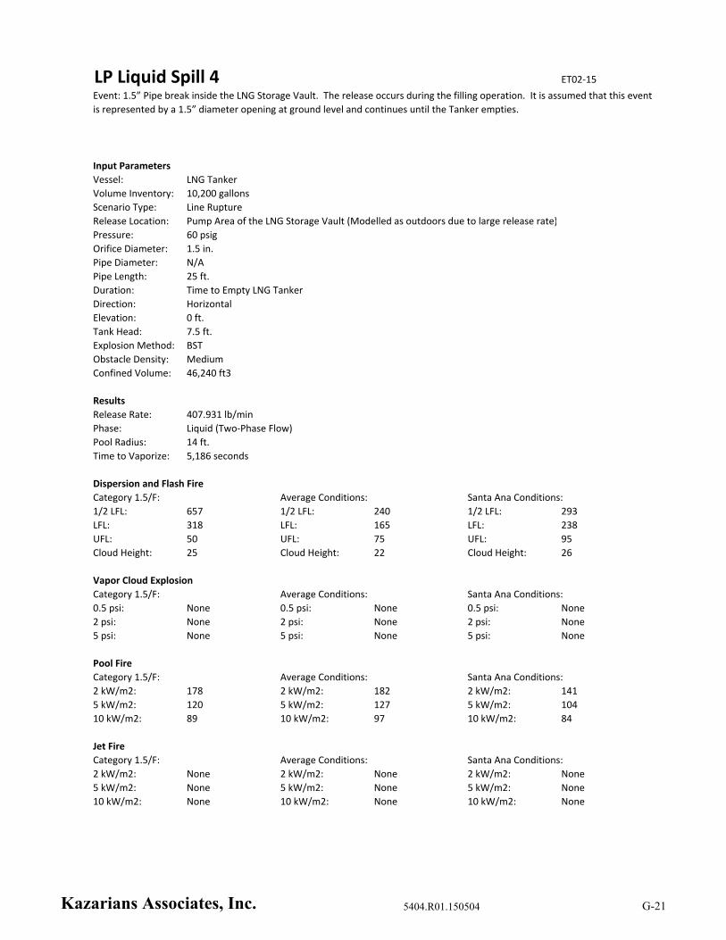
LP Liquid Spill 4 ET02‐15
Input Parameters
Vessel: LNG Tanker
Volume Inventory: 10,200 gallons
Scenario Type: Line Rupture
Release Location: Pump Area of the LNG Storage Vault (Modelled as outdoors due to large release rate)
Pressure: 60 psig
Orifice Diameter: 1.5 in.
Pipe Diameter: N/A
Pipe Length: 25 ft.
Duration: Time to Empty LNG Tanker
Direction: Horizontal
Elevation: 0 ft.
Tank Head: 7.5 ft.
Explosion Method: BST
Obstacle Density: Medium
Confined Volume: 46,240 ft3
Results
Release Rate: 407.931 lb/min
Phase: Liquid (Two‐Phase Flow)
Pool Radius: 14 ft.
Time to Vaporize: 5,186 seconds
Dispersion and Flash Fire
1/2 LFL: 657 1/2 LFL: 240 1/2 LFL: 293
LFL: 318 LFL: 165 LFL: 238
UFL: 50 UFL: 75 UFL: 95
Cloud Height: 25 Cloud Height: 22 Cloud Height: 26
Vapor Cloud Explosion
Category 1.5/F: Average Conditions: Santa Ana Conditions:
0.5 psi: None 0.5 psi: None 0.5 psi: None
2 psi: None 2 psi: None 2 psi: None
5 psi: None 5 psi: None 5 psi: None
Pool Fire
Category 1.5/F: Average Conditions: Santa Ana Conditions:
2 kW/m2: 178 2 kW/m2: 182 2 kW/m2: 141
5 kW/m2: 120 5 kW/m2: 127 5 kW/m2: 104
10 kW/m2: 89 10 kW/m2: 97 10 kW/m2: 84
Jet Fire
Category 1.5/F: Average Conditions: Santa Ana Conditions:
2 kW/m2: None 2 kW/m2: None 2 kW/m2: None
5 kW/m2: None 5 kW/m2: None 5 kW/m2: None
10 kW/m2: None 10 kW/m2: None 10 kW/m2: None
Event: 1.5” Pipe break inside the LNG Storage Vault. The release occurs during the filling operation. It is assumed that this event
is represented by a 1.5” diameter opening at ground level and continues until the Tanker empties.
Category 1.5/F: Average Conditions: Santa Ana Conditions:
Kazarians Associates, Inc. 5404.R01.150504 G-21

LP Liquid Spill 5 No Offsite Cons.
Input Parameters
Vessel: LNG Storage Tank
Volume Inventory: 30,000 gallons
Scenario Type: Line Rupture
Release Location: Pump Area of the LNG Storage Vault
Pressure: 120 psig
Orifice Diameter: 1/4 in.
Pipe Diameter: N/A
Pipe Length: 25 ft.
Duration: Time to Empty Storage Tank
Direction: Horizontal
Elevation: 0 ft.
Tank Head: 10 ft.
Explosion Method: BST
Obstacle Density: Medium
Confined Volume: 46,240 ft3
Results
Release Rate: 7.71335 lb/min
Phase: Liquid (Two‐Phase Flow)
Pool Radius: N/A
Time to Vaporize: N/A
Dispersion and Flash Fire
1/2 LFL: 7 1/2 LFL: 3.1 1/2 LFL: 1.5
LFL: None LFL: None LFL: None
UFL: None UFL: None UFL: None
Cloud Height: 6 Cloud Height: 5 Cloud Height: 4.6
Vapor Cloud Explosion
Category 1.5/F: Average Conditions: Santa Ana Conditions:
0.5 psi: None 0.5 psi: None 0.5 psi: None
2 psi: None 2 psi: None 2 psi: None
5 psi: None 5 psi: None 5 psi: None
Pool Fire
Category 1.5/F: Average Conditions: Santa Ana Conditions:
2 kW/m2: None 2 kW/m2: None 2 kW/m2: None
5 kW/m2: None 5 kW/m2: None 5 kW/m2: None
10 kW/m2: None 10 kW/m2: None 10 kW/m2: None
Jet Fire
Category 1.5/F: Average Conditions: Santa Ana Conditions:
2 kW/m2: None 2 kW/m2: None 2 kW/m2: None
5 kW/m2: None 5 kW/m2: None 5 kW/m2: None
10 kW/m2: None 10 kW/m2: None 10 kW/m2: None
Event: 1/4” Pipe break inside the LNG Storage Vault. The release occurs downstream of the LNG Pumps. It is assumed that this
event is represented by a 1/4” diameter opening at ground level and continues until the Storage Tank empties.
Category 1.5/F: Average Conditions: Santa Ana Conditions:
Kazarians Associates, Inc. 5404.R01.150504 G-22

LP Liquid Spill 6 ET02‐03
Input Parameters
Vessel: LNG Storage Tank
Volume Inventory: 30,000 gallons
Scenario Type: Line Rupture
Release Location: Pump Area of the LNG Storage Vault
Pressure: 120 psig
Orifice Diameter: 1/2 in.
Pipe Diameter: N/A
Pipe Length: 25 ft.
Duration: Time to Empty Storage Tank
Direction: Horizontal
Elevation: 0 ft.
Tank Head: 10 ft.
Explosion Method: BST
Obstacle Density: Medium
Confined Volume: 46,240 ft3
Results
Release Rate: 43.5415 lb/min
Phase: Liquid (Two‐Phase Flow)
Pool Radius: N/A
Time to Vaporize: N/A
Dispersion and Flash Fire
1/2 LFL: 128 1/2 LFL: 28 1/2 LFL: 18
LFL: 48 LFL: 13 LFL: 8
UFL: 5 UFL: 2 UFL: 1
Cloud Height: 4 Cloud Height: 2 Cloud Height: 1
Vapor Cloud Explosion
Category 1.5/F: Average Conditions: Santa Ana Conditions:
0.5 psi: None 0.5 psi: None 0.5 psi: None
2 psi: None 2 psi: None 2 psi: None
5 psi: None 5 psi: None 5 psi: None
Pool Fire
Category 1.5/F: Average Conditions: Santa Ana Conditions:
2 kW/m2: None 2 kW/m2: None 2 kW/m2: None
5 kW/m2: None 5 kW/m2: None 5 kW/m2: None
10 kW/m2: None 10 kW/m2: None 10 kW/m2: None
Jet Fire
Category 1.5/F: Average Conditions: Santa Ana Conditions:
2 kW/m2: None 2 kW/m2: None 2 kW/m2: None
5 kW/m2: None 5 kW/m2: None 5 kW/m2: None
10 kW/m2: None 10 kW/m2: None 10 kW/m2: None
Event: 1/2” Pipe break inside the LNG Storage Vault. The release occurs downstream of the LNG Pumps. It is assumed that this
event is represented by a 1/2” diameter opening at ground level and continues until the Storage Tank empties.
Category 1.5/F: Average Conditions: Santa Ana Conditions:
Kazarians Associates, Inc. 5404.R01.150504 G-23
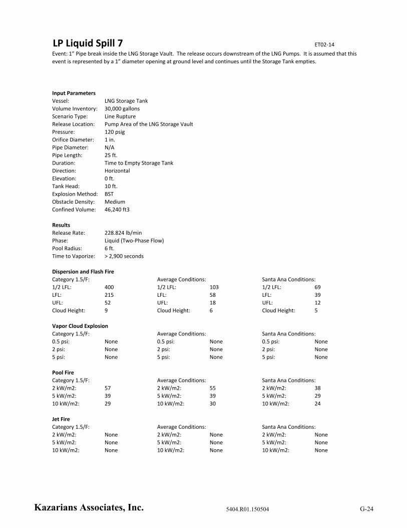
LP Liquid Spill 7 ET02‐14
Input Parameters
Vessel: LNG Storage Tank
Volume Inventory: 30,000 gallons
Scenario Type: Line Rupture
Release Location: Pump Area of the LNG Storage Vault
Pressure: 120 psig
Orifice Diameter: 1 in.
Pipe Diameter: N/A
Pipe Length: 25 ft.
Duration: Time to Empty Storage Tank
Direction: Horizontal
Elevation: 0 ft.
Tank Head: 10 ft.
Explosion Method: BST
Obstacle Density: Medium
Confined Volume: 46,240 ft3
Results
Release Rate: 228.824 lb/min
Phase: Liquid (Two‐Phase Flow)
Pool Radius: 6 ft.
Time to Vaporize: > 2,900 seconds
Dispersion and Flash Fire
1/2 LFL: 400 1/2 LFL: 103 1/2 LFL: 69
LFL: 215 LFL: 58 LFL: 39
UFL: 52 UFL: 18 UFL: 12
Cloud Height: 9 Cloud Height: 6 Cloud Height: 5
Vapor Cloud Explosion
Category 1.5/F: Average Conditions: Santa Ana Conditions:
0.5 psi: None 0.5 psi: None 0.5 psi: None
2 psi: None 2 psi: None 2 psi: None
5 psi: None 5 psi: None 5 psi: None
Pool Fire
Category 1.5/F: Average Conditions: Santa Ana Conditions:
2 kW/m2: 57 2 kW/m2: 55 2 kW/m2: 38
5 kW/m2: 39 5 kW/m2: 39 5 kW/m2: 29
10 kW/m2: 29 10 kW/m2: 30 10 kW/m2: 24
Jet Fire
Category 1.5/F: Average Conditions: Santa Ana Conditions:
2 kW/m2: None 2 kW/m2: None 2 kW/m2: None
5 kW/m2: None 5 kW/m2: None 5 kW/m2: None
10 kW/m2: None 10 kW/m2: None 10 kW/m2: None
Event: 1” Pipe break inside the LNG Storage Vault. The release occurs downstream of the LNG Pumps. It is assumed that this
event is represented by a 1” diameter opening at ground level and continues until the Storage Tank empties.
Category 1.5/F: Average Conditions: Santa Ana Conditions:
Kazarians Associates, Inc. 5404.R01.150504 G-24
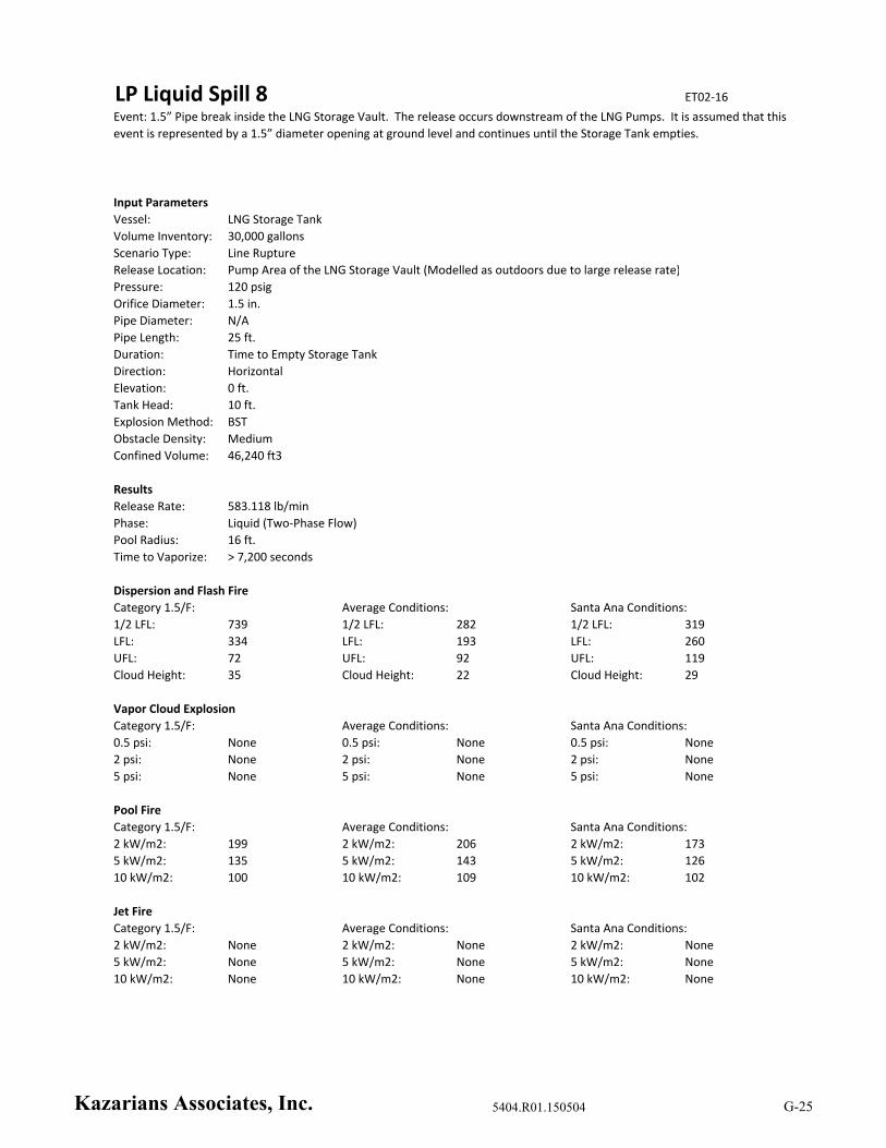
LP Liquid Spill 8 ET02‐16
Input Parameters
Vessel: LNG Storage Tank
Volume Inventory: 30,000 gallons
Scenario Type: Line Rupture
Release Location: Pump Area of the LNG Storage Vault (Modelled as outdoors due to large release rate)
Pressure: 120 psig
Orifice Diameter: 1.5 in.
Pipe Diameter: N/A
Pipe Length: 25 ft.
Duration: Time to Empty Storage Tank
Direction: Horizontal
Elevation: 0 ft.
Tank Head: 10 ft.
Explosion Method: BST
Obstacle Density: Medium
Confined Volume: 46,240 ft3
Results
Release Rate: 583.118 lb/min
Phase: Liquid (Two‐Phase Flow)
Pool Radius: 16 ft.
Time to Vaporize: > 7,200 seconds
Dispersion and Flash Fire
1/2 LFL: 739 1/2 LFL: 282 1/2 LFL: 319
LFL: 334 LFL: 193 LFL: 260
UFL: 72 UFL: 92 UFL: 119
Cloud Height: 35 Cloud Height: 22 Cloud Height: 29
Vapor Cloud Explosion
Category 1.5/F: Average Conditions: Santa Ana Conditions:
0.5 psi: None 0.5 psi: None 0.5 psi: None
2 psi: None 2 psi: None 2 psi: None
5 psi: None 5 psi: None 5 psi: None
Pool Fire
Category 1.5/F: Average Conditions: Santa Ana Conditions:
2 kW/m2: 199 2 kW/m2: 206 2 kW/m2: 173
5 kW/m2: 135 5 kW/m2: 143 5 kW/m2: 126
10 kW/m2: 100 10 kW/m2: 109 10 kW/m2: 102
Jet Fire
Category 1.5/F: Average Conditions: Santa Ana Conditions:
2 kW/m2: None 2 kW/m2: None 2 kW/m2: None
5 kW/m2: None 5 kW/m2: None 5 kW/m2: None
10 kW/m2: None 10 kW/m2: None 10 kW/m2: None
Event: 1.5” Pipe break inside the LNG Storage Vault. The release occurs downstream of the LNG Pumps. It is assumed that this
event is represented by a 1.5” diameter opening at ground level and continues until the Storage Tank empties.
Category 1.5/F: Average Conditions: Santa Ana Conditions:
Kazarians Associates, Inc. 5404.R01.150504 G-25

LP Vapor Venting 1 ET01‐08
Input Parameters
Vessel: LNG Storage Tank
Volume Inventory: 10,000 gallons
Scenario Type: Relief Valve
Release Location: LNG Storage Tank Vault Roof Vent
Pressure: 120 psig
Orifice Diameter: 3/4 in.
Pipe Diameter: 1.5 in.
Pipe Length: 25 ft.
Duration: Time to Empty Storage Tank
Direction: Vertical
Elevation: 12 ft.
Tank Head: 0 ft.
Explosion Method: BST
Obstacle Density: Low
Confined Volume: 1 m3
Results
Release Rate: 95.6799 lb/min
Phase: Vapor
Pool Radius: N/A
Time to Vaporize: N/A
Dispersion and Flash Fire
1/2 LFL: 5 1/2 LFL: 4.7 1/2 LFL: 5.3
LFL: 1.8 LFL: 2.1 LFL: 2.4
UFL: 0.4 UFL: 0.5 UFL: 0.6
Cloud Height: 40 Cloud Height: 30 Cloud Height: 21
Vapor Cloud Explosion
Category 1.5/F: Average Conditions: Santa Ana Conditions:
0.5 psi: None 0.5 psi: None 0.5 psi: None
2 psi: None 2 psi: None 2 psi: None
5 psi: None 5 psi: None 5 psi: None
Pool Fire
Category 1.5/F: Average Conditions: Santa Ana Conditions:
2 kW/m2: None 2 kW/m2: None 2 kW/m2: None
5 kW/m2: None 5 kW/m2: None 5 kW/m2: None
10 kW/m2: None 10 kW/m2: None 10 kW/m2: None
Jet Fire
Category 1.5/F: Average Conditions: Santa Ana Conditions:
2 kW/m2: 35 2 kW/m2: 49 2 kW/m2: 55
5 kW/m2: None 5 kW/m2: None 5 kW/m2: 36
10 kW/m2: None 10 kW/m2: None 10 kW/m2: 23
Event: Spurious lift of a PSV on a 1/3 full Storage Tank. It is assumed that this event is represented by a 3/4” diameter opening
at 12 ft. elevation and continues until the Storage Tank empties.
Category 1.5/F: Average Conditions: Santa Ana Conditions:
Kazarians Associates, Inc. 5404.R01.150504 G-26

LP Vapor Venting 2 ET01‐09
Input Parameters
Vessel: LNG Storage Tank
Volume Inventory: 30,000 gallons
Scenario Type: Relief Valve
Release Location: LNG Storage Tank Vault Roof Vent
Pressure: 40 psig
Orifice Diameter: 3/4 in.
Pipe Diameter: 1.5 in.
Pipe Length: 25 ft.
Duration: Time to Empty Storage Tank
Direction: Vertical
Elevation: 12 ft.
Tank Head: 0 ft.
Explosion Method: BST
Obstacle Density: Low
Confined Volume: 1 m3
Results
Release Rate: 38.3336 lb/min
Phase: Vapor
Pool Radius: N/A
Time to Vaporize: N/A
Dispersion and Flash Fire
1/2 LFL: 5 1/2 LFL: 4.7 1/2 LFL: 5.4
LFL: 2 LFL: 2.2 LFL: 2.4
UFL: 0.5 UFL: 0.5 UFL: 0.6
Cloud Height: 31 Cloud Height: 23 Cloud Height: 17
Vapor Cloud Explosion
Category 1.5/F: Average Conditions: Santa Ana Conditions:
0.5 psi: None 0.5 psi: None 0.5 psi: None
2 psi: None 2 psi: None 2 psi: None
5 psi: None 5 psi: None 5 psi: None
Pool Fire
Category 1.5/F: Average Conditions: Santa Ana Conditions:
2 kW/m2: None 2 kW/m2: None 2 kW/m2: None
5 kW/m2: None 5 kW/m2: None 5 kW/m2: None
10 kW/m2: None 10 kW/m2: None 10 kW/m2: None
Jet Fire
Category 1.5/F: Average Conditions: Santa Ana Conditions:
2 kW/m2: None 2 kW/m2: 33 2 kW/m2: 43
5 kW/m2: None 5 kW/m2: None 5 kW/m2: 28
10 kW/m2: None 10 kW/m2: None 10 kW/m2: 16
Event: Spurious lift of a PSV on a full Storage Tank. It is assumed that this event is represented by a 3/4” diameter opening at 12
ft. elevation and continues until the Storage Tank empties.
Category 1.5/F: Average Conditions: Santa Ana Conditions:
Kazarians Associates, Inc. 5404.R01.150504 G-27

LP Vapor Venting 3 No Offsite Cons.
Input Parameters
Vessel: LNG Pump Pot
Volume Inventory: 1.77 ft3
Scenario Type: Relief Valve
Release Location: LNG Storage Tank Vault Roof Vent
Pressure: 60 psig
Orifice Diameter: 1/4 in.
Pipe Diameter: 1.5 in.
Pipe Length: 40 ft.
Duration: Time to Empty Pump Pot
Direction: Vertical
Elevation: 12 ft.
Tank Head: 2.5 ft.
Explosion Method: BST
Obstacle Density: Low
Confined Volume: 1 m3
Results
Release Rate: 5.86123 lb/min
Phase: Vapor
Pool Radius: N/A
Time to Vaporize: N/A
Dispersion and Flash Fire
1/2 LFL: 5 1/2 LFL: 6 1/2 LFL: 6.3
LFL: 2.2 LFL: 2.6 LFL: 2.9
UFL: 0.6 UFL: 0.6 UFL: 0.8
Cloud Height: 19 Cloud Height: 16 Cloud Height: 14
Vapor Cloud Explosion
Category 1.5/F: Average Conditions: Santa Ana Conditions:
0.5 psi: None 0.5 psi: None 0.5 psi: None
2 psi: None 2 psi: None 2 psi: None
5 psi: None 5 psi: None 5 psi: None
Pool Fire
Category 1.5/F: Average Conditions: Santa Ana Conditions:
2 kW/m2: None 2 kW/m2: None 2 kW/m2: None
5 kW/m2: None 5 kW/m2: None 5 kW/m2: None
10 kW/m2: None 10 kW/m2: None 10 kW/m2: None
Jet Fire
Category 1.5/F: Average Conditions: Santa Ana Conditions:
2 kW/m2: None 2 kW/m2: None 2 kW/m2: 17
5 kW/m2: None 5 kW/m2: None 5 kW/m2: None
10 kW/m2: None 10 kW/m2: None 10 kW/m2: None
Event: Spurious lift of a PSV on the standby pump pot. It is assumed that this event is represented by a 1/4” diameter opening at
12 ft. elevation and continues until the pump pot empties.
Category 1.5/F: Average Conditions: Santa Ana Conditions:
Kazarians Associates, Inc. 5404.R01.150504 G-28
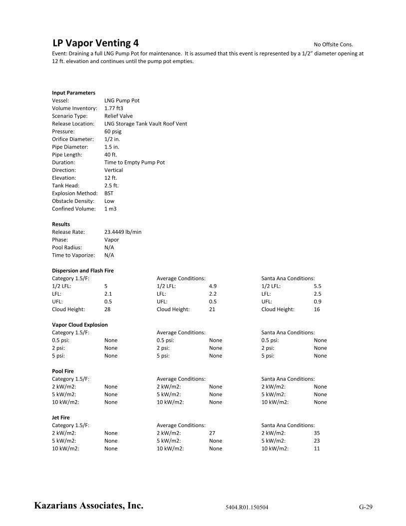
LP Vapor Venting 4 No Offsite Cons.
Input Parameters
Vessel: LNG Pump Pot
Volume Inventory: 1.77 ft3
Scenario Type: Relief Valve
Release Location: LNG Storage Tank Vault Roof Vent
Pressure: 60 psig
Orifice Diameter: 1/2 in.
Pipe Diameter: 1.5 in.
Pipe Length: 40 ft.
Duration: Time to Empty Pump Pot
Direction: Vertical
Elevation: 12 ft.
Tank Head: 2.5 ft.
Explosion Method: BST
Obstacle Density: Low
Confined Volume: 1 m3
Results
Release Rate: 23.4449 lb/min
Phase: Vapor
Pool Radius: N/A
Time to Vaporize: N/A
Dispersion and Flash Fire
1/2 LFL: 5 1/2 LFL: 4.9 1/2 LFL: 5.5
LFL: 2.1 LFL: 2.2 LFL: 2.5
UFL: 0.5 UFL: 0.5 UFL: 0.9
Cloud Height: 28 Cloud Height: 21 Cloud Height: 16
Vapor Cloud Explosion
Category 1.5/F: Average Conditions: Santa Ana Conditions:
0.5 psi: None 0.5 psi: None 0.5 psi: None
2 psi: None 2 psi: None 2 psi: None
5 psi: None 5 psi: None 5 psi: None
Pool Fire
Category 1.5/F: Average Conditions: Santa Ana Conditions:
2 kW/m2: None 2 kW/m2: None 2 kW/m2: None
5 kW/m2: None 5 kW/m2: None 5 kW/m2: None
10 kW/m2: None 10 kW/m2: None 10 kW/m2: None
Jet Fire
Category 1.5/F: Average Conditions: Santa Ana Conditions:
2 kW/m2: None 2 kW/m2: 27 2 kW/m2: 35
5 kW/m2: None 5 kW/m2: None 5 kW/m2: 23
10 kW/m2: None 10 kW/m2: None 10 kW/m2: 11
Event: Draining a full LNG Pump Pot for maintenance. It is assumed that this event is represented by a 1/2” diameter opening at
12 ft. elevation and continues until the pump pot empties.
Category 1.5/F: Average Conditions: Santa Ana Conditions:
Kazarians Associates, Inc. 5404.R01.150504 G-29

LP Vapor Release 1 No Offsite Cons.
Input Parameters
Vessel: LNG Pump Pot (Connected to LNG Storage Tank)
Volume Inventory: 10,000 gallons
Scenario Type: Leak
Release Location: LNG Storage Tank Vault Pump Area
Pressure: 120 psig
Orifice Diameter: 10 mm
Pipe Diameter: N/A
Pipe Length: N/A
Duration: 1 Hour
Direction: Horizontal
Elevation: 10 ft.
Tank Head: 0 ft.
Explosion Method: BST
Obstacle Density: Medium
Confined Volume: 46,240 ft3
Results
Release Rate: 21.971 lb/min
Phase: Vapor
Pool Radius: N/A
Time to Vaporize: N/A
Dispersion and Flash Fire
1/2 LFL: 7 1/2 LFL: 6 1/2 LFL: 4
LFL: 3 LFL: 2 LFL: 1
UFL: None UFL: None UFL: None
Cloud Height: 20 Cloud Height: 20 Cloud Height: 18
Vapor Cloud Explosion
Category 1.5/F: Average Conditions: Santa Ana Conditions:
0.5 psi: None 0.5 psi: None 0.5 psi: None
2 psi: None 2 psi: None 2 psi: None
5 psi: None 5 psi: None 5 psi: None
Pool Fire
Category 1.5/F: Average Conditions: Santa Ana Conditions:
2 kW/m2: None 2 kW/m2: None 2 kW/m2: None
5 kW/m2: None 5 kW/m2: None 5 kW/m2: None
10 kW/m2: None 10 kW/m2: None 10 kW/m2: None
Jet Fire
Category 1.5/F: Average Conditions: Santa Ana Conditions:
2 kW/m2: None 2 kW/m2: None 2 kW/m2: None
5 kW/m2: None 5 kW/m2: None 5 kW/m2: None
10 kW/m2: None 10 kW/m2: None 10 kW/m2: None
Event: Flange leak on a Storage Tank or Pump Pot. It is assumed that this event is represented by a 10 mm diameter opening at
ground level, and continues for 1 hour.
Category 1.5/F: Average Conditions: Santa Ana Conditions:
Kazarians Associates, Inc. 5404.R01.150504 G-30

LP Vapor Release 2 No Offsite Cons.
Input Parameters
Vessel: LNG Pump Pot (Connected to LNG Storage Tank)
Volume Inventory: 10,000 gallons
Scenario Type: Leak
Release Location: LNG Storage Tank Vault Pump Area
Pressure: 120 psig
Orifice Diameter: 10 mm
Pipe Diameter: N/A
Pipe Length: N/A
Duration: Time to Empty Storage Tank
Direction: Horizontal
Elevation: 10 ft.
Tank Head: 0 ft.
Explosion Method: BST
Obstacle Density: Medium
Confined Volume: 46,240 ft3
Results
Release Rate: 21.971 lb/min
Phase: Vapor
Pool Radius: N/A
Time to Vaporize: N/A
Dispersion and Flash Fire
1/2 LFL: 7 1/2 LFL: 6 1/2 LFL: 4
LFL: 3 LFL: 2 LFL: 1
UFL: None UFL: None UFL: None
Cloud Height: 20 Cloud Height: 20 Cloud Height: 18
Vapor Cloud Explosion
Category 1.5/F: Average Conditions: Santa Ana Conditions:
0.5 psi: None 0.5 psi: None 0.5 psi: None
2 psi: None 2 psi: None 2 psi: None
5 psi: None 5 psi: None 5 psi: None
Pool Fire
Category 1.5/F: Average Conditions: Santa Ana Conditions:
2 kW/m2: None 2 kW/m2: None 2 kW/m2: None
5 kW/m2: None 5 kW/m2: None 5 kW/m2: None
10 kW/m2: None 10 kW/m2: None 10 kW/m2: None
Jet Fire
Category 1.5/F: Average Conditions: Santa Ana Conditions:
2 kW/m2: None 2 kW/m2: None 2 kW/m2: None
5 kW/m2: None 5 kW/m2: None 5 kW/m2: None
10 kW/m2: None 10 kW/m2: None 10 kW/m2: None
Event: Flange leak on a Storage Tank or Pump Pot. It is assumed that this event is represented by a 10 mm diameter opening at
ground level, and continues until the Storage Tank empties.
Category 1.5/F: Average Conditions: Santa Ana Conditions:
Kazarians Associates, Inc. 5404.R01.150504 G-31

Storage Tank Spill 1 ET02‐01
Input Parameters
Vessel: LNG Storage Tank
Volume Inventory: 30,000 gallons
Scenario Type: Line Rupture
Release Location: Pump Area of the LNG Storage Vault (Modelled as outdoors due to large release rate)
Pressure: 40 psig
Orifice Diameter: 3 in.
Pipe Diameter: N/A
Pipe Length: 25 ft.
Duration: Time to Empty Storage Tank
Direction: Horizontal
Elevation: 0 ft.
Tank Head: 10 ft.
Explosion Method: BST
Obstacle Density: Medium
Confined Volume: 46,240 ft3
Results
Release Rate: 1,619.43 lb/min
Phase: Liquid (Two‐Phase Flow)
Pool Radius: 16 ft.
Time to Vaporize: > 7,200 seconds
Dispersion and Flash Fire
1/2 LFL: 899 1/2 LFL: 335 1/2 LFL: 412
LFL: 332 LFL: 239 LFL: 330
UFL: 70 UFL: 106 UFL: 138
Cloud Height: 32 Cloud Height: 30 Cloud Height: 35
Vapor Cloud Explosion
Category 1.5/F: Average Conditions: Santa Ana Conditions:
0.5 psi: None 0.5 psi: None 0.5 psi: None
2 psi: None 2 psi: None 2 psi: None
5 psi: None 5 psi: None 5 psi: None
Pool Fire
Category 1.5/F: Average Conditions: Santa Ana Conditions:
2 kW/m2: 199 2 kW/m2: 206 2 kW/m2: 173
5 kW/m2: 135 5 kW/m2: 143 5 kW/m2: 126
10 kW/m2: 100 10 kW/m2: 109 10 kW/m2: 102
Jet Fire
Category 1.5/F: Average Conditions: Santa Ana Conditions:
2 kW/m2: None 2 kW/m2: None 2 kW/m2: None
5 kW/m2: None 5 kW/m2: None 5 kW/m2: None
10 kW/m2: None 10 kW/m2: None 10 kW/m2: None
Event: 3” Pipe break inside the LNG Storage Vault. The release occurs upstream of the LNG Pumps. It is assumed that this event
is represented by a 3” diameter opening at ground level and continues until the Storage Tank empties.
Category 1.5/F: Average Conditions: Santa Ana Conditions:
Kazarians Associates, Inc. 5404.R01.150504 G-32

Storage Tank Spill 2 No Offsite Cons.
Input Parameters
Vessel: LNG Storage Tank
Volume Inventory: 30,000 gallons
Scenario Type: Line Rupture
Release Location: LNG Storage Tank Vault Roof Vent
Pressure: 120 psig
Orifice Diameter: 1/4 in.
Pipe Diameter: N/A
Pipe Length: 40 ft.
Duration: Time to Empty Storage Tank
Direction: Vertical
Elevation: 12 ft.
Tank Head: 10 ft.
Explosion Method: BST
Obstacle Density: Low
Confined Volume: 1 m3
Results
Release Rate: 6.23889 lb/min
Phase: Liquid (Two‐Phase Flow)
Pool Radius: N/A
Time to Vaporize: N/A
Dispersion and Flash Fire
1/2 LFL: 2 1/2 LFL: 1.9 1/2 LFL: 2
LFL: 0.8 LFL: 0.9 LFL: 1
UFL: 0.2 UFL: 0.2 UFL: 0.3
Cloud Height: 21 Cloud Height: 17 Cloud Height: 15
Vapor Cloud Explosion
Category 1.5/F: Average Conditions: Santa Ana Conditions:
0.5 psi: None 0.5 psi: None 0.5 psi: None
2 psi: None 2 psi: None 2 psi: None
5 psi: None 5 psi: None 5 psi: None
Pool Fire
Category 1.5/F: Average Conditions: Santa Ana Conditions:
2 kW/m2: None 2 kW/m2: None 2 kW/m2: None
5 kW/m2: None 5 kW/m2: None 5 kW/m2: None
10 kW/m2: None 10 kW/m2: None 10 kW/m2: None
Jet Fire
Category 1.5/F: Average Conditions: Santa Ana Conditions:
2 kW/m2: None 2 kW/m2: None 2 kW/m2: 12
5 kW/m2: None 5 kW/m2: None 5 kW/m2: None
10 kW/m2: None 10 kW/m2: None 10 kW/m2: None
Event: A drain valve upstream of the high pressure pumps is left open before starting the system. It is assumed that this event is
represented by a 1/4” diameter opening at 12 ft. elevation, and continues until the Storage Tank empties.
Category 1.5/F: Average Conditions: Santa Ana Conditions:
Kazarians Associates, Inc. 5404.R01.150504 G-33
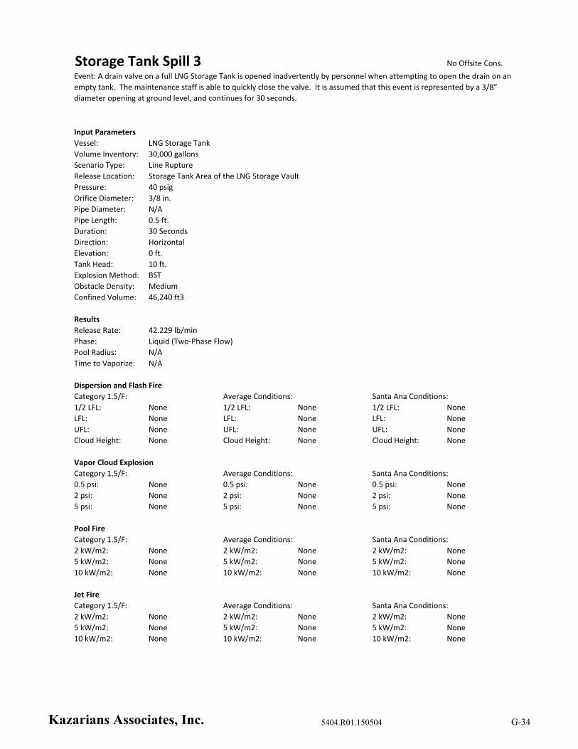
Storage Tank Spill 3 No Offsite Cons.
Input Parameters
Vessel: LNG Storage Tank
Volume Inventory: 30,000 gallons
Scenario Type: Line Rupture
Release Location: Storage Tank Area of the LNG Storage Vault
Pressure: 40 psig
Orifice Diameter: 3/8 in.
Pipe Diameter: N/A
Pipe Length: 0.5 ft.
Duration: 30 Seconds
Direction: Horizontal
Elevation: 0 ft.
Tank Head: 10 ft.
Explosion Method: BST
Obstacle Density: Medium
Confined Volume: 46,240 ft3
Results
Release Rate: 42.229 lb/min
Phase: Liquid (Two‐Phase Flow)
Pool Radius: N/A
Time to Vaporize: N/A
Dispersion and Flash Fire
1/2 LFL: None 1/2 LFL: None 1/2 LFL: None
LFL: None LFL: None LFL: None
UFL: None UFL: None UFL: None
Cloud Height: None Cloud Height: None Cloud Height: None
Vapor Cloud Explosion
Category 1.5/F: Average Conditions: Santa Ana Conditions:
0.5 psi: None 0.5 psi: None 0.5 psi: None
2 psi: None 2 psi: None 2 psi: None
5 psi: None 5 psi: None 5 psi: None
Pool Fire
Category 1.5/F: Average Conditions: Santa Ana Conditions:
2 kW/m2: None 2 kW/m2: None 2 kW/m2: None
5 kW/m2: None 5 kW/m2: None 5 kW/m2: None
10 kW/m2: None 10 kW/m2: None 10 kW/m2: None
Jet Fire
Category 1.5/F: Average Conditions: Santa Ana Conditions:
2 kW/m2: None 2 kW/m2: None 2 kW/m2: None
5 kW/m2: None 5 kW/m2: None 5 kW/m2: None
10 kW/m2: None 10 kW/m2: None 10 kW/m2: None
Event: A drain valve on a full LNG Storage Tank is opened inadvertently by personnel when attempting to open the drain on an
empty tank. The maintenance staff is able to quickly close the valve. It is assumed that this event is represented by a 3/8”
diameter opening at ground level, and continues for 30 seconds.
Category 1.5/F: Average Conditions: Santa Ana Conditions:
Kazarians Associates, Inc. 5404.R01.150504 G-34
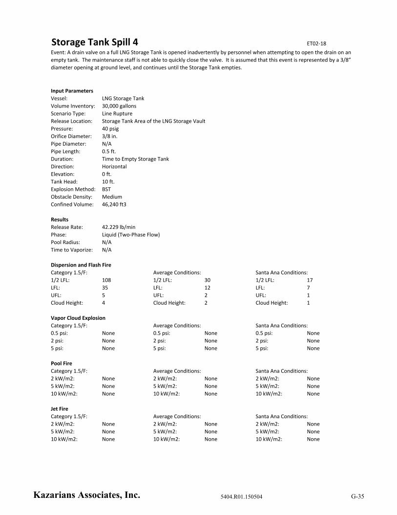
Storage Tank Spill 4 ET02‐18
Input Parameters
Vessel: LNG Storage Tank
Volume Inventory: 30,000 gallons
Scenario Type: Line Rupture
Release Location: Storage Tank Area of the LNG Storage Vault
Pressure: 40 psig
Orifice Diameter: 3/8 in.
Pipe Diameter: N/A
Pipe Length: 0.5 ft.
Duration: Time to Empty Storage Tank
Direction: Horizontal
Elevation: 0 ft.
Tank Head: 10 ft.
Explosion Method: BST
Obstacle Density: Medium
Confined Volume: 46,240 ft3
Results
Release Rate: 42.229 lb/min
Phase: Liquid (Two‐Phase Flow)
Pool Radius: N/A
Time to Vaporize: N/A
Dispersion and Flash Fire
1/2 LFL: 108 1/2 LFL: 30 1/2 LFL: 17
LFL: 35 LFL: 12 LFL: 7
UFL: 5 UFL: 2 UFL: 1
Cloud Height: 4 Cloud Height: 2 Cloud Height: 1
Vapor Cloud Explosion
Category 1.5/F: Average Conditions: Santa Ana Conditions:
0.5 psi: None 0.5 psi: None 0.5 psi: None
2 psi: None 2 psi: None 2 psi: None
5 psi: None 5 psi: None 5 psi: None
Pool Fire
Category 1.5/F: Average Conditions: Santa Ana Conditions:
2 kW/m2: None 2 kW/m2: None 2 kW/m2: None
5 kW/m2: None 5 kW/m2: None 5 kW/m2: None
10 kW/m2: None 10 kW/m2: None 10 kW/m2: None
Jet Fire
Category 1.5/F: Average Conditions: Santa Ana Conditions:
2 kW/m2: None 2 kW/m2: None 2 kW/m2: None
5 kW/m2: None 5 kW/m2: None 5 kW/m2: None
10 kW/m2: None 10 kW/m2: None 10 kW/m2: None
Event: A drain valve on a full LNG Storage Tank is opened inadvertently by personnel when attempting to open the drain on an
empty tank. The maintenance staff is not able to quickly close the valve. It is assumed that this event is represented by a 3/8”
diameter opening at ground level, and continues until the Storage Tank empties.
Category 1.5/F: Average Conditions: Santa Ana Conditions:
Kazarians Associates, Inc. 5404.R01.150504 G-35

Storage Tank Spill 5 No Offsite Cons.
Input Parameters
Vessel: LNG Storage Tank
Volume Inventory: 30,000 gallons
Scenario Type: Relief Valve Lift
Release Location: LNG Storage Tank Vault Roof Vent
Pressure: 200 psig
Orifice Diameter: 1/4 in.
Pipe Diameter: 1.5 in.
Pipe Length: 40 ft.
Duration: Time to Empty Storage Tank
Direction: Vertical
Elevation: 12 ft.
Tank Head: 10 ft.
Explosion Method: BST
Obstacle Density: Low
Confined Volume: 1 m3
Results
Release Rate: 41.1204 lb/min
Phase: Liquid (Two‐Phase Flow)
Pool Radius: N/A
Time to Vaporize: N/A
Dispersion and Flash Fire
1/2 LFL: 9 1/2 LFL: 9.8 1/2 LFL: 9.1
LFL: 4 LFL: 4.3 LFL: 4.7
UFL: 1 UFL: 1.2 UFL: 1.2
Cloud Height: 31 Cloud Height: 23 Cloud Height: 17
Vapor Cloud Explosion
Category 1.5/F: Average Conditions: Santa Ana Conditions:
0.5 psi: None 0.5 psi: None 0.5 psi: None
2 psi: None 2 psi: None 2 psi: None
5 psi: None 5 psi: None 5 psi: None
Pool Fire
Category 1.5/F: Average Conditions: Santa Ana Conditions:
2 kW/m2: None 2 kW/m2: None 2 kW/m2: None
5 kW/m2: None 5 kW/m2: None 5 kW/m2: None
10 kW/m2: None 10 kW/m2: None 10 kW/m2: None
Jet Fire
Category 1.5/F: Average Conditions: Santa Ana Conditions:
2 kW/m2: 34 2 kW/m2: 44 2 kW/m2: 46
5 kW/m2: None 5 kW/m2: 25 5 kW/m2: 33
10 kW/m2: None 10 kW/m2: None 10 kW/m2: 24
Event: A valve downstream of the LNG Pumps is indavertently left closed. Deadhead of the LNG Pumps, resulting in lifting the
downstream relief valve to the vent. It is assumed that this event is represented by a 1/4” diameter opening at 12 ft. elevation,
and continues until the Storage Tank empties.
Category 1.5/F: Average Conditions: Santa Ana Conditions:
Kazarians Associates, Inc. 5404.R01.150504 G-36
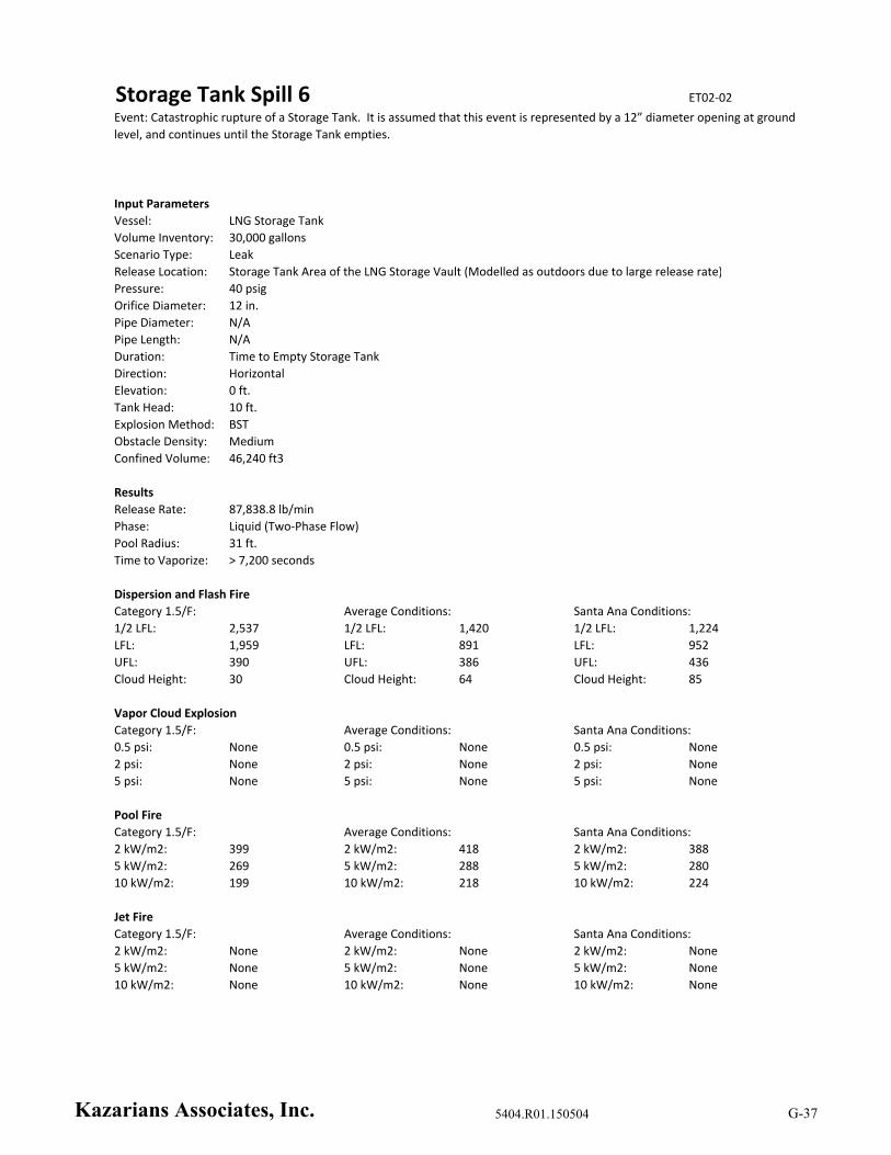
Storage Tank Spill 6 ET02‐02
Input Parameters
Vessel: LNG Storage Tank
Volume Inventory: 30,000 gallons
Scenario Type: Leak
Release Location: Storage Tank Area of the LNG Storage Vault (Modelled as outdoors due to large release rate)
Pressure: 40 psig
Orifice Diameter: 12 in.
Pipe Diameter: N/A
Pipe Length: N/A
Duration: Time to Empty Storage Tank
Direction: Horizontal
Elevation: 0 ft.
Tank Head: 10 ft.
Explosion Method: BST
Obstacle Density: Medium
Confined Volume: 46,240 ft3
Results
Release Rate: 87,838.8 lb/min
Phase: Liquid (Two‐Phase Flow)
Pool Radius: 31 ft.
Time to Vaporize: > 7,200 seconds
Dispersion and Flash Fire
1/2 LFL: 2,537 1/2 LFL: 1,420 1/2 LFL: 1,224
LFL: 1,959 LFL: 891 LFL: 952
UFL: 390 UFL: 386 UFL: 436
Cloud Height: 30 Cloud Height: 64 Cloud Height: 85
Vapor Cloud Explosion
Category 1.5/F: Average Conditions: Santa Ana Conditions:
0.5 psi: None 0.5 psi: None 0.5 psi: None
2 psi: None 2 psi: None 2 psi: None
5 psi: None 5 psi: None 5 psi: None
Pool Fire
Category 1.5/F: Average Conditions: Santa Ana Conditions:
2 kW/m2: 399 2 kW/m2: 418 2 kW/m2: 388
5 kW/m2: 269 5 kW/m2: 288 5 kW/m2: 280
10 kW/m2: 199 10 kW/m2: 218 10 kW/m2: 224
Jet Fire
Category 1.5/F: Average Conditions: Santa Ana Conditions:
2 kW/m2: None 2 kW/m2: None 2 kW/m2: None
5 kW/m2: None 5 kW/m2: None 5 kW/m2: None
10 kW/m2: None 10 kW/m2: None 10 kW/m2: None
Event: Catastrophic rupture of a Storage Tank. It is assumed that this event is represented by a 12” diameter opening at ground
level, and continues until the Storage Tank empties.
Category 1.5/F: Average Conditions: Santa Ana Conditions:
Kazarians Associates, Inc. 5404.R01.150504 G-37
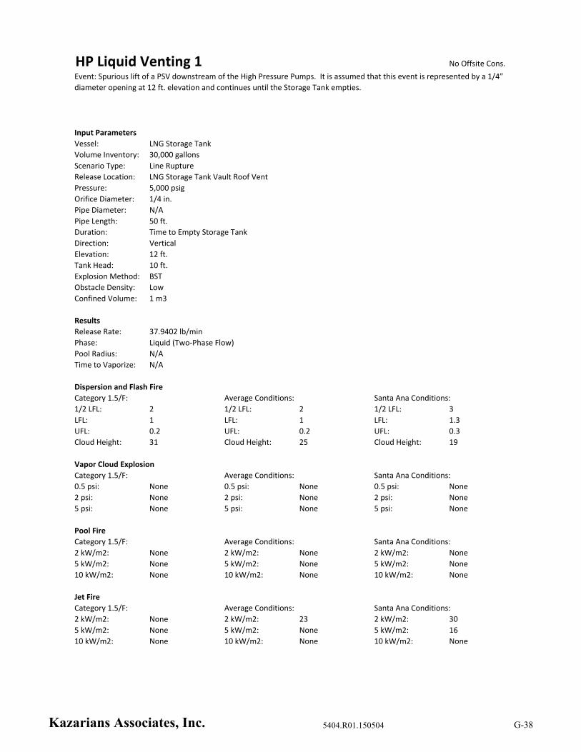
HP Liquid Venting 1 No Offsite Cons.
Input Parameters
Vessel: LNG Storage Tank
Volume Inventory: 30,000 gallons
Scenario Type: Line Rupture
Release Location: LNG Storage Tank Vault Roof Vent
Pressure: 5,000 psig
Orifice Diameter: 1/4 in.
Pipe Diameter: N/A
Pipe Length: 50 ft.
Duration: Time to Empty Storage Tank
Direction: Vertical
Elevation: 12 ft.
Tank Head: 10 ft.
Explosion Method: BST
Obstacle Density: Low
Confined Volume: 1 m3
Results
Release Rate: 37.9402 lb/min
Phase: Liquid (Two‐Phase Flow)
Pool Radius: N/A
Time to Vaporize: N/A
Dispersion and Flash Fire
1/2 LFL: 2 1/2 LFL: 2 1/2 LFL: 3
LFL: 1 LFL: 1 LFL: 1.3
UFL: 0.2 UFL: 0.2 UFL: 0.3
Cloud Height: 31 Cloud Height: 25 Cloud Height: 19
Vapor Cloud Explosion
Category 1.5/F: Average Conditions: Santa Ana Conditions:
0.5 psi: None 0.5 psi: None 0.5 psi: None
2 psi: None 2 psi: None 2 psi: None
5 psi: None 5 psi: None 5 psi: None
Pool Fire
Category 1.5/F: Average Conditions: Santa Ana Conditions:
2 kW/m2: None 2 kW/m2: None 2 kW/m2: None
5 kW/m2: None 5 kW/m2: None 5 kW/m2: None
10 kW/m2: None 10 kW/m2: None 10 kW/m2: None
Jet Fire
Category 1.5/F: Average Conditions: Santa Ana Conditions:
2 kW/m2: None 2 kW/m2: 23 2 kW/m2: 30
5 kW/m2: None 5 kW/m2: None 5 kW/m2: 16
10 kW/m2: None 10 kW/m2: None 10 kW/m2: None
Event: Spurious lift of a PSV downstream of the High Pressure Pumps. It is assumed that this event is represented by a 1/4”
diameter opening at 12 ft. elevation and continues until the Storage Tank empties.
Category 1.5/F: Average Conditions: Santa Ana Conditions:
Kazarians Associates, Inc. 5404.R01.150504 G-38

HP Liquid Venting 2 No Offsite Cons.
Input Parameters
Vessel: 1” x 8’ Piping Segment
Volume Inventory: 0.044 ft3
Scenario Type: Relief Valve
Release Location: LNG Storage Tank Vault Roof Vent
Pressure: 5,500 psig
Orifice Diameter: 1/4 in.
Pipe Diameter: 1.5 in.
Pipe Length: 50 ft.
Duration: Time to empty pipe segment
Direction: Vertical
Elevation: 12 ft.
Tank Head: 0 ft.
Explosion Method: BST
Obstacle Density: Low
Confined Volume: 1 m3
Results
Release Rate: 50.3451 lb/min
Phase: Liquid (Two‐Phase Flow)
Pool Radius: N/A
Time to Vaporize: N/A
Dispersion and Flash Fire
1/2 LFL: 3 1/2 LFL: 3 1/2 LFL: 3
LFL: 1 LFL: 1.2 LFL: 1.5
UFL: 0.3 UFL: 0.3 UFL: 0.4
Cloud Height: 33 Cloud Height: 27 Cloud Height: 20
Vapor Cloud Explosion
Category 1.5/F: Average Conditions: Santa Ana Conditions:
0.5 psi: None 0.5 psi: None 0.5 psi: None
2 psi: None 2 psi: None 2 psi: None
5 psi: None 5 psi: None 5 psi: None
Pool Fire
Category 1.5/F: Average Conditions: Santa Ana Conditions:
2 kW/m2: None 2 kW/m2: None 2 kW/m2: None
5 kW/m2: None 5 kW/m2: None 5 kW/m2: None
10 kW/m2: None 10 kW/m2: None 10 kW/m2: None
Jet Fire
Category 1.5/F: Average Conditions: Santa Ana Conditions:
2 kW/m2: None 2 kW/m2: 29 2 kW/m2: 36
5 kW/m2: None 5 kW/m2: None 5 kW/m2: 20
10 kW/m2: None 10 kW/m2: None 10 kW/m2: None
Event: Thermal expansion of a blocked in segment of 1” piping downstream of the High Pressure Pumps causes the thermal PSV
to lift to the roof vent and the valve does not re‐seat. It is assumed that this event is represented by a 1/4” diameter opening at
12 ft. elevation and continues until the pipe segment empties.
Category 1.5/F: Average Conditions: Santa Ana Conditions:
Kazarians Associates, Inc. 5404.R01.150504 G-39

HP Liquid Venting 3 No Offsite Cons.
Input Parameters
Vessel: LNG Storage Tank
Volume Inventory: 30,000 gallons
Scenario Type: Relief Valve
Release Location: LNG Storage Tank Vault Roof Vent
Pressure: 200 psig
Orifice Diameter: 1/4 in.
Pipe Diameter: 1.5 in.
Pipe Length: 50 ft.
Duration: Time to Empty Storage Tank
Direction: Vertical
Elevation: 12 ft.
Tank Head: 10 ft.
Explosion Method: BST
Obstacle Density: Low
Confined Volume: 1 m3
Results
Release Rate: 7.19318 lb/min
Phase: Liquid (Two‐Phase Flow)
Pool Radius: N/A
Time to Vaporize: N/A
Dispersion and Flash Fire
1/2 LFL: 2 1/2 LFL: 2 1/2 LFL: 2
LFL: 1 LFL: 0.8 LFL: 1
UFL: 0.2 UFL: 0.2 UFL: 0.2
Cloud Height: 21 Cloud Height: 18 Cloud Height: 15
Vapor Cloud Explosion
Category 1.5/F: Average Conditions: Santa Ana Conditions:
0.5 psi: None 0.5 psi: None 0.5 psi: None
2 psi: None 2 psi: None 2 psi: None
5 psi: None 5 psi: None 5 psi: None
Pool Fire
Category 1.5/F: Average Conditions: Santa Ana Conditions:
2 kW/m2: None 2 kW/m2: None 2 kW/m2: None
5 kW/m2: None 5 kW/m2: None 5 kW/m2: None
10 kW/m2: None 10 kW/m2: None 10 kW/m2: None
Jet Fire
Category 1.5/F: Average Conditions: Santa Ana Conditions:
2 kW/m2: None 2 kW/m2: None 2 kW/m2: 13
5 kW/m2: None 5 kW/m2: None 5 kW/m2: None
10 kW/m2: None 10 kW/m2: None 10 kW/m2: None
Event: The bottom fill valve on one of the High Pressure Pumps fails open. Circulation of high pressure material back to the
Storage Tanks, resulting in lifting the 200 psi PSVs on the bottom fill line. It is assumed that this event is represented by a 1/4”
diameter opening at 12 ft. elevation and continues until the Storage Tank empties.
Category 1.5/F: Average Conditions: Santa Ana Conditions:
Kazarians Associates, Inc. 5404.R01.150504 G-40

HP Liquid Venting 4 No Offsite Cons.
Input Parameters
Vessel: 1” x 8’ Piping Segment
Volume Inventory: 0.044 ft3
Scenario Type: Relief Valve
Release Location: LNG Storage Tank Vault Roof Vent
Pressure: 5,500 psig
Orifice Diameter: 1/4 in.
Pipe Diameter: 1.5 in.
Pipe Length: 50 ft.
Duration: 5 Seconds
Direction: Vertical
Elevation: 12 ft.
Tank Head: 10 ft.
Explosion Method: BST
Obstacle Density: Low
Confined Volume: 1 m3
Results
Release Rate: 50.3451 lb/min
Phase: Liquid (Two‐Phase Flow)
Pool Radius: N/A
Time to Vaporize: N/A
Dispersion and Flash Fire
1/2 LFL: 3 1/2 LFL: 3 1/2 LFL: 3
LFL: 1 LFL: 1.2 LFL: 1.5
UFL: 0.3 UFL: 0.3 UFL: 0.4
Cloud Height: 33 Cloud Height: 27 Cloud Height: 20
Vapor Cloud Explosion
Category 1.5/F: Average Conditions: Santa Ana Conditions:
0.5 psi: None 0.5 psi: None 0.5 psi: None
2 psi: None 2 psi: None 2 psi: None
5 psi: None 5 psi: None 5 psi: None
Pool Fire
Category 1.5/F: Average Conditions: Santa Ana Conditions:
2 kW/m2: None 2 kW/m2: None 2 kW/m2: None
5 kW/m2: None 5 kW/m2: None 5 kW/m2: None
10 kW/m2: None 10 kW/m2: None 10 kW/m2: None
Jet Fire
Category 1.5/F: Average Conditions: Santa Ana Conditions:
2 kW/m2: None 2 kW/m2: 29 2 kW/m2: 36
5 kW/m2: None 5 kW/m2: None 5 kW/m2: 20
10 kW/m2: None 10 kW/m2: None 10 kW/m2: None
Event: Thermal expansion of a blocked in segment of 1” piping downstream of the High Pressure Pumps causes the thermal PSV
to lift to the roof vent and the valve re‐seats. It is assumed that this event is represented by a 1/4” diameter opening at 12 ft.
elevation and continues for 5 seconds.
Category 1.5/F: Average Conditions: Santa Ana Conditions:
Kazarians Associates, Inc. 5404.R01.150504 G-41
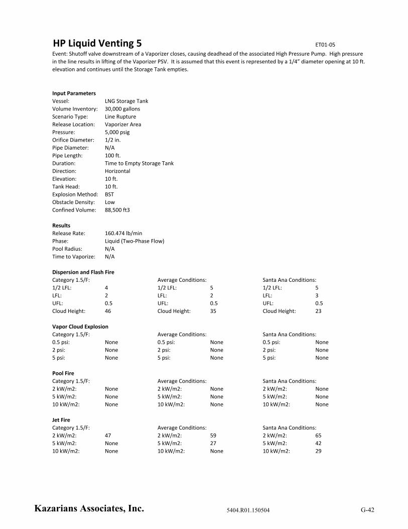
HP Liquid Venting 5 ET01‐05
Input Parameters
Vessel: LNG Storage Tank
Volume Inventory: 30,000 gallons
Scenario Type: Line Rupture
Release Location: Vaporizer Area
Pressure: 5,000 psig
Orifice Diameter: 1/2 in.
Pipe Diameter: N/A
Pipe Length: 100 ft.
Duration: Time to Empty Storage Tank
Direction: Horizontal
Elevation: 10 ft.
Tank Head: 10 ft.
Explosion Method: BST
Obstacle Density: Low
Confined Volume: 88,500 ft3
Results
Release Rate: 160.474 lb/min
Phase: Liquid (Two‐Phase Flow)
Pool Radius: N/A
Time to Vaporize: N/A
Dispersion and Flash Fire
1/2 LFL: 4 1/2 LFL: 5 1/2 LFL: 5
LFL: 2 LFL: 2 LFL: 3
UFL: 0.5 UFL: 0.5 UFL: 0.5
Cloud Height: 46 Cloud Height: 35 Cloud Height: 23
Vapor Cloud Explosion
Category 1.5/F: Average Conditions: Santa Ana Conditions:
0.5 psi: None 0.5 psi: None 0.5 psi: None
2 psi: None 2 psi: None 2 psi: None
5 psi: None 5 psi: None 5 psi: None
Pool Fire
Category 1.5/F: Average Conditions: Santa Ana Conditions:
2 kW/m2: None 2 kW/m2: None 2 kW/m2: None
5 kW/m2: None 5 kW/m2: None 5 kW/m2: None
10 kW/m2: None 10 kW/m2: None 10 kW/m2: None
Jet Fire
Category 1.5/F: Average Conditions: Santa Ana Conditions:
2 kW/m2: 47 2 kW/m2: 59 2 kW/m2: 65
5 kW/m2: None 5 kW/m2: 27 5 kW/m2: 42
10 kW/m2: None 10 kW/m2: None 10 kW/m2: 29
Event: Shutoff valve downstream of a Vaporizer closes, causing deadhead of the associated High Pressure Pump. High pressure
in the line results in lifting of the Vaporizer PSV. It is assumed that this event is represented by a 1/4” diameter opening at 10 ft.
elevation and continues until the Storage Tank empties.
Category 1.5/F: Average Conditions: Santa Ana Conditions:
Kazarians Associates, Inc. 5404.R01.150504 G-42
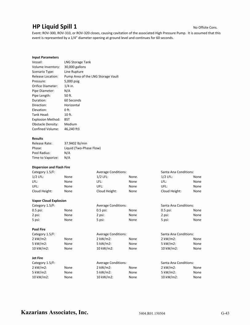
HP Liquid Spill 1 No Offsite Cons.
Input Parameters
Vessel: LNG Storage Tank
Volume Inventory: 30,000 gallons
Scenario Type: Line Rupture
Release Location: Pump Area of the LNG Storage Vault
Pressure: 5,000 psig
Orifice Diameter: 1/4 in.
Pipe Diameter: N/A
Pipe Length: 50 ft.
Duration: 60 Seconds
Direction: Horizontal
Elevation: 0 ft.
Tank Head: 10 ft.
Explosion Method: BST
Obstacle Density: Medium
Confined Volume: 46,240 ft3
Results
Release Rate: 37.9402 lb/min
Phase: Liquid (Two‐Phase Flow)
Pool Radius: N/A
Time to Vaporize: N/A
Dispersion and Flash Fire
1/2 LFL: None 1/2 LFL: None. 1/2 LFL: None
LFL: None LFL: None LFL: None
UFL: None UFL: None UFL: None
Cloud Height: None Cloud Height: None Cloud Height: None
Vapor Cloud Explosion
Category 1.5/F: Average Conditions: Santa Ana Conditions:
0.5 psi: None 0.5 psi: None 0.5 psi: None
2 psi: None 2 psi: None 2 psi: None
5 psi: None 5 psi: None 5 psi: None
Pool Fire
Category 1.5/F: Average Conditions: Santa Ana Conditions:
2 kW/m2: None 2 kW/m2: None 2 kW/m2: None
5 kW/m2: None 5 kW/m2: None 5 kW/m2: None
10 kW/m2: None 10 kW/m2: None 10 kW/m2: None
Jet Fire
Category 1.5/F: Average Conditions: Santa Ana Conditions:
2 kW/m2: None 2 kW/m2: None 2 kW/m2: None
5 kW/m2: None 5 kW/m2: None 5 kW/m2: None
10 kW/m2: None 10 kW/m2: None 10 kW/m2: None
Event: ROV‐300, ROV‐310, or ROV‐320 closes, causing cavitation of the associated High Pressure Pump. It is assumed that this
event is represented by a 1/4” diameter opening at ground level and continues for 60 seconds.
Category 1.5/F: Average Conditions: Santa Ana Conditions:
Kazarians Associates, Inc. 5404.R01.150504 G-43
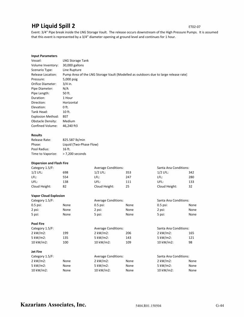
HP Liquid Spill 2 ET02‐07
Input Parameters
Vessel: LNG Storage Tank
Volume Inventory: 30,000 gallons
Scenario Type: Line Rupture
Release Location: Pump Area of the LNG Storage Vault (Modelled as outdoors due to large release rate)
Pressure: 5,000 psig
Orifice Diameter: 3/4 in.
Pipe Diameter: N/A
Pipe Length: 50 ft.
Duration: 1 Hour
Direction: Horizontal
Elevation: 0 ft.
Tank Head: 10 ft.
Explosion Method: BST
Obstacle Density: Medium
Confined Volume: 46,240 ft3
Results
Release Rate: 825.587 lb/min
Phase: Liquid (Two‐Phase Flow)
Pool Radius: 16 ft.
Time to Vaporize: > 7,200 seconds
Dispersion and Flash Fire
1/2 LFL: 698 1/2 LFL: 353 1/2 LFL: 342
LFL: 554 LFL: 247 LFL: 280
UFL: 138 UFL: 111 UFL: 133
Cloud Height: 82 Cloud Height: 25 Cloud Height: 32
Vapor Cloud Explosion
Category 1.5/F: Average Conditions: Santa Ana Conditions:
0.5 psi: None 0.5 psi: None 0.5 psi: None
2 psi: None 2 psi: None 2 psi: None
5 psi: None 5 psi: None 5 psi: None
Pool Fire
Category 1.5/F: Average Conditions: Santa Ana Conditions:
2 kW/m2: 199 2 kW/m2: 206 2 kW/m2: 165
5 kW/m2: 135 5 kW/m2: 143 5 kW/m2: 121
10 kW/m2: 100 10 kW/m2: 109 10 kW/m2: 98
Jet Fire
Category 1.5/F: Average Conditions: Santa Ana Conditions:
2 kW/m2: None 2 kW/m2: None 2 kW/m2: None
5 kW/m2: None 5 kW/m2: None 5 kW/m2: None
10 kW/m2: None 10 kW/m2: None 10 kW/m2: None
Event: 3/4” Pipe break inside the LNG Storage Vault. The release occurs downstream of the High Pressure Pumps. It is assumed
that this event is represented by a 3/4” diameter opening at ground level and continues for 1 hour.
Category 1.5/F: Average Conditions: Santa Ana Conditions:
Kazarians Associates, Inc. 5404.R01.150504 G-44

HP Liquid Spill 3 ET02‐08
Input Parameters
Vessel: LNG Storage Tank
Volume Inventory: 30,000 gallons
Scenario Type: Line Rupture
Release Location: Pump Area of the LNG Storage Vault (Modelled as outdoors due to large release rate)
Pressure: 5,000 psig
Orifice Diameter: 1 in.
Pipe Diameter: N/A
Pipe Length: 50 ft.
Duration: Time to Empty Storage Tank
Direction: Horizontal
Elevation: 0 ft.
Tank Head: 10 ft.
Explosion Method: BST
Obstacle Density: Medium
Confined Volume: 46,240 ft3
Results
Release Rate: 1,685.93 lb/min
Phase: Liquid (Two‐Phase Flow)
Pool Radius: 16 ft.
Time to Vaporize: > 7,200 seconds
Dispersion and Flash Fire
1/2 LFL: 929 1/2 LFL: 486 1/2 LFL: 456
LFL: 740 LFL: 332 LFL: 368
UFL: 184 UFL: 147 UFL: 177
Cloud Height: 104 Cloud Height: 32 Cloud Height: 40
Vapor Cloud Explosion
Category 1.5/F: Average Conditions: Santa Ana Conditions:
0.5 psi: None 0.5 psi: None 0.5 psi: None
2 psi: None 2 psi: None 2 psi: None
5 psi: None 5 psi: None 5 psi: None
Pool Fire
Category 1.5/F: Average Conditions: Santa Ana Conditions:
2 kW/m2: 199 2 kW/m2: 206 2 kW/m2: 192
5 kW/m2: 135 5 kW/m2: 143 5 kW/m2: 138
10 kW/m2: 100 10 kW/m2: 109 10 kW/m2: 113
Jet Fire
Category 1.5/F: Average Conditions: Santa Ana Conditions:
2 kW/m2: None 2 kW/m2: None 2 kW/m2: None
5 kW/m2: None 5 kW/m2: None 5 kW/m2: None
10 kW/m2: None 10 kW/m2: None 10 kW/m2: None
Event: 1” Pipe break inside the LNG Storage Vault. The release occurs downstream of the High Pressure Pumps. It is assumed
that this event is represented by a 1” diameter opening at ground level and continues until the Storage Tank empties.
Category 1.5/F: Average Conditions: Santa Ana Conditions:
Kazarians Associates, Inc. 5404.R01.150504 G-45

HP Liquid Spill 4 ET03‐03
Input Parameters
Vessel: LNG Storage Tank
Volume Inventory: 30,000 gallons
Scenario Type: Line Rupture
Release Location: Vaporizer Area
Pressure: 5,000 psig
Orifice Diameter: 1 in.
Pipe Diameter: N/A
Pipe Length: 70 ft.
Duration: Time to Empty Storage Tank
Direction: Horizontal
Elevation: 0 ft.
Tank Head: 10 ft.
Explosion Method: BST
Obstacle Density: Low
Confined Volume: 88,500 ft3
Results
Release Rate: 1,434.25 lb/min
Phase: Liquid (Two‐Phase Flow)
Pool Radius: 23 ft.
Time to Vaporize: 4,698 seconds
Dispersion and Flash Fire
1/2 LFL: 885 1/2 LFL: 467 1/2 LFL: 443
LFL: 700 LFL: 317 LFL: 358
UFL: 170 UFL: 142 UFL: 172
Cloud Height: 99 Cloud Height: 30 Cloud Height: 39
Vapor Cloud Explosion
Category 1.5/F: Average Conditions: Santa Ana Conditions:
0.5 psi: None 0.5 psi: None 0.5 psi: None
2 psi: None 2 psi: None 2 psi: None
5 psi: None 5 psi: None 5 psi: None
Pool Fire
Category 1.5/F: Average Conditions: Santa Ana Conditions:
2 kW/m2: 308 2 kW/m2: 324 2 kW/m2: 251
5 kW/m2: 208 5 kW/m2: 224 5 kW/m2: 182
10 kW/m2: 154 10 kW/m2: 154 10 kW/m2: 146
Jet Fire
Category 1.5/F: Average Conditions: Santa Ana Conditions:
2 kW/m2: 257 2 kW/m2: 239 2 kW/m2: 220
5 kW/m2: 216 5 kW/m2: 194 5 kW/m2: 174
10 kW/m2: 194 10 kW/m2: 170 10 kW/m2: 150
Event: 1” Pipe break outside near the Vaporizers. The release occurs downstream of the High Pressure Pumps. It is assumed
that this event is represented by a 1” diameter opening at ground level and continues until the Storage Tank empties.
Category 1.5/F: Average Conditions: Santa Ana Conditions:
Kazarians Associates, Inc. 5404.R01.150504 G-46
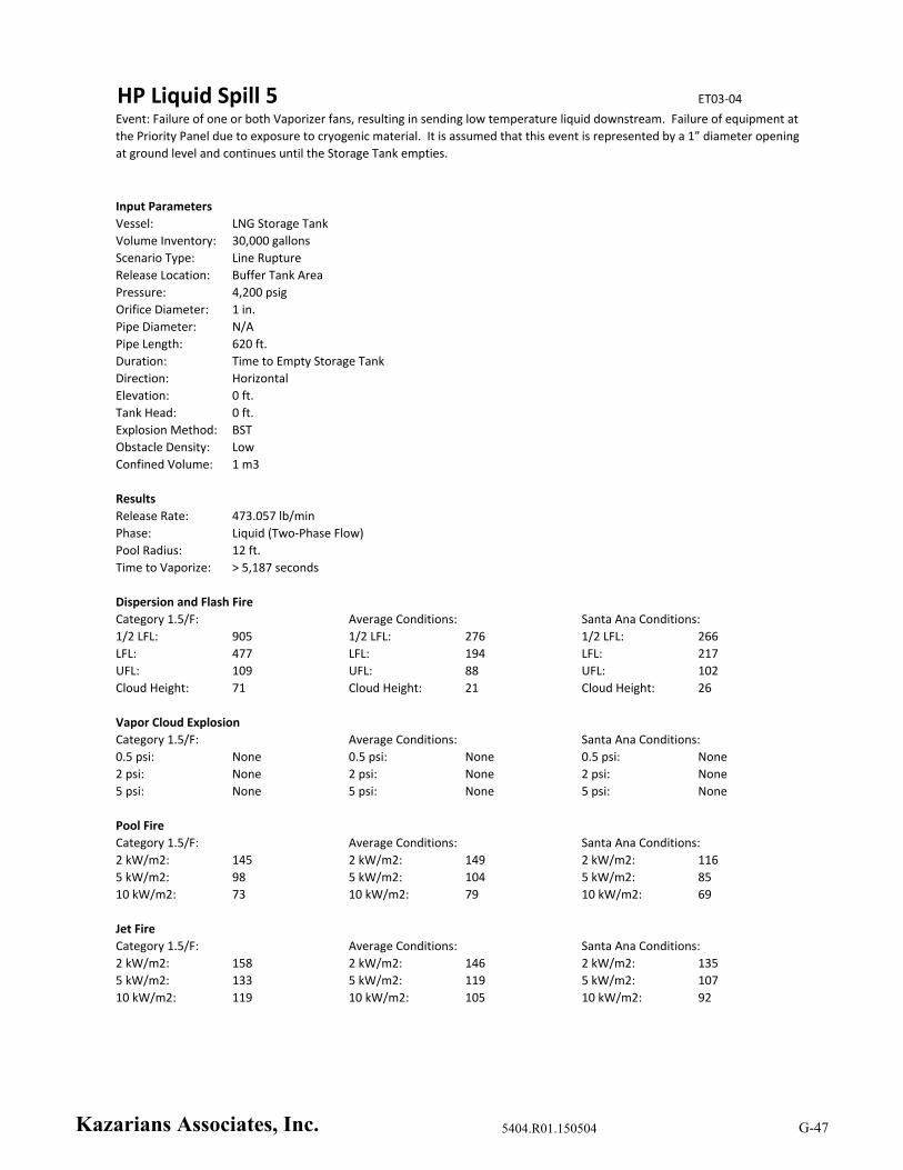
HP Liquid Spill 5 ET03‐04
Input Parameters
Vessel: LNG Storage Tank
Volume Inventory: 30,000 gallons
Scenario Type: Line Rupture
Release Location: Buffer Tank Area
Pressure: 4,200 psig
Orifice Diameter: 1 in.
Pipe Diameter: N/A
Pipe Length: 620 ft.
Duration: Time to Empty Storage Tank
Direction: Horizontal
Elevation: 0 ft.
Tank Head: 0 ft.
Explosion Method: BST
Obstacle Density: Low
Confined Volume: 1 m3
Results
Release Rate: 473.057 lb/min
Phase: Liquid (Two‐Phase Flow)
Pool Radius: 12 ft.
Time to Vaporize: > 5,187 seconds
Dispersion and Flash Fire
1/2 LFL: 905 1/2 LFL: 276 1/2 LFL: 266
LFL: 477 LFL: 194 LFL: 217
UFL: 109 UFL: 88 UFL: 102
Cloud Height: 71 Cloud Height: 21 Cloud Height: 26
Vapor Cloud Explosion
Category 1.5/F: Average Conditions: Santa Ana Conditions:
0.5 psi: None 0.5 psi: None 0.5 psi: None
2 psi: None 2 psi: None 2 psi: None
5 psi: None 5 psi: None 5 psi: None
Pool Fire
Category 1.5/F: Average Conditions: Santa Ana Conditions:
2 kW/m2: 145 2 kW/m2: 149 2 kW/m2: 116
5 kW/m2: 98 5 kW/m2: 104 5 kW/m2: 85
10 kW/m2: 73 10 kW/m2: 79 10 kW/m2: 69
Jet Fire
Category 1.5/F: Average Conditions: Santa Ana Conditions:
2 kW/m2: 158 2 kW/m2: 146 2 kW/m2: 135
5 kW/m2: 133 5 kW/m2: 119 5 kW/m2: 107
10 kW/m2: 119 10 kW/m2: 105 10 kW/m2: 92
Event: Failure of one or both Vaporizer fans, resulting in sending low temperature liquid downstream. Failure of equipment at
the Priority Panel due to exposure to cryogenic material. It is assumed that this event is represented by a 1” diameter opening
at ground level and continues until the Storage Tank empties.
Category 1.5/F: Average Conditions: Santa Ana Conditions:
Kazarians Associates, Inc. 5404.R01.150504 G-47
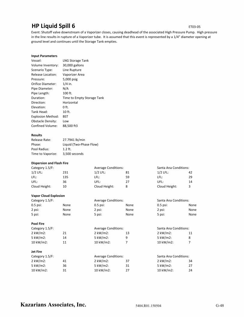
HP Liquid Spill 6 ET03‐05
Input Parameters
Vessel: LNG Storage Tank
Volume Inventory: 30,000 gallons
Scenario Type: Line Rupture
Release Location: Vaporizer Area
Pressure: 5,000 psig
Orifice Diameter: 1/4 in.
Pipe Diameter: N/A
Pipe Length: 100 ft.
Duration: Time to Empty Storage Tank
Direction: Horizontal
Elevation: 0 ft.
Tank Head: 10 ft.
Explosion Method: BST
Obstacle Density: Low
Confined Volume: 88,500 ft3
Results
Release Rate: 27.7941 lb/min
Phase: Liquid (Two‐Phase Flow)
Pool Radius: 1.2 ft.
Time to Vaporize: 3,500 seconds
Dispersion and Flash Fire
1/2 LFL: 231 1/2 LFL: 81 1/2 LFL: 42
LFL: 135 LFL: 59 LFL: 29
UFL: 36 UFL: 27 UFL: 14
Cloud Height: 10 Cloud Height: 8 Cloud Height: 3
Vapor Cloud Explosion
Category 1.5/F: Average Conditions: Santa Ana Conditions:
0.5 psi: None 0.5 psi: None 0.5 psi: None
2 psi: None 2 psi: None 2 psi: None
5 psi: None 5 psi: None 5 psi: None
Pool Fire
Category 1.5/F: Average Conditions: Santa Ana Conditions:
2 kW/m2: 21 2 kW/m2: 13 2 kW/m2: 11
5 kW/m2: 14 5 kW/m2: 9 5 kW/m2: 8
10 kW/m2: 11 10 kW/m2: 7 10 kW/m2: 7
Jet Fire
Category 1.5/F: Average Conditions: Santa Ana Conditions:
2 kW/m2: 41 2 kW/m2: 37 2 kW/m2: 34
5 kW/m2: 36 5 kW/m2: 31 5 kW/m2: 27
10 kW/m2: 31 10 kW/m2: 27 10 kW/m2: 24
Event: Shutoff valve downstream of a Vaporizer closes, causing deadhead of the associated High Pressure Pump. High pressure
in the line results in rupture of a Vaporizer tube. It is assumed that this event is represented by a 1/4” diameter opening at
ground level and continues until the Storage Tank empties.
Category 1.5/F: Average Conditions: Santa Ana Conditions:
Kazarians Associates, Inc. 5404.R01.150504 G-48
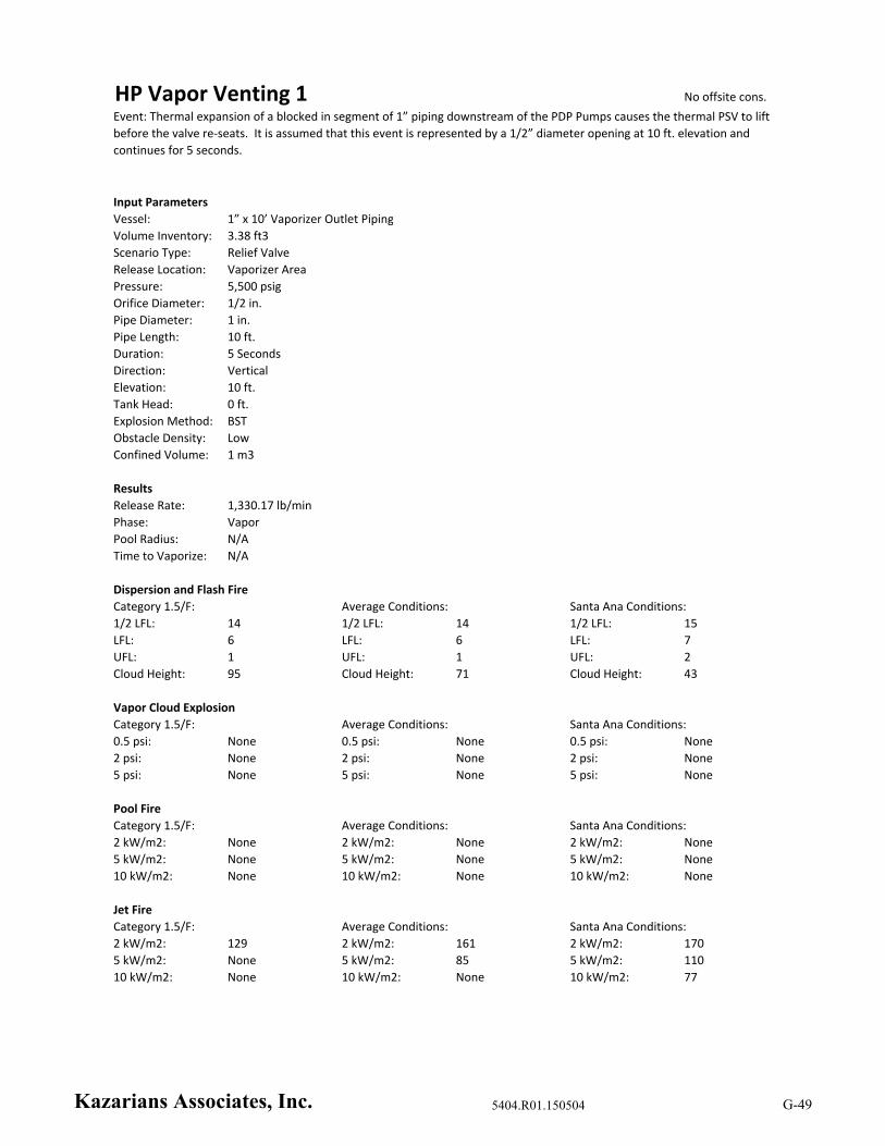
HP Vapor Venting 1 No offsite cons.
Input Parameters
Vessel: 1” x 10’ Vaporizer Outlet Piping
Volume Inventory: 3.38 ft3
Scenario Type: Relief Valve
Release Location: Vaporizer Area
Pressure: 5,500 psig
Orifice Diameter: 1/2 in.
Pipe Diameter: 1 in.
Pipe Length: 10 ft.
Duration: 5 Seconds
Direction: Vertical
Elevation: 10 ft.
Tank Head: 0 ft.
Explosion Method: BST
Obstacle Density: Low
Confined Volume: 1 m3
Results
Release Rate: 1,330.17 lb/min
Phase: Vapor
Pool Radius: N/A
Time to Vaporize: N/A
Dispersion and Flash Fire
1/2 LFL: 14 1/2 LFL: 14 1/2 LFL: 15
LFL: 6 LFL: 6 LFL: 7
UFL: 1 UFL: 1 UFL: 2
Cloud Height: 95 Cloud Height: 71 Cloud Height: 43
Vapor Cloud Explosion
Category 1.5/F: Average Conditions: Santa Ana Conditions:
0.5 psi: None 0.5 psi: None 0.5 psi: None
2 psi: None 2 psi: None 2 psi: None
5 psi: None 5 psi: None 5 psi: None
Pool Fire
Category 1.5/F: Average Conditions: Santa Ana Conditions:
2 kW/m2: None 2 kW/m2: None 2 kW/m2: None
5 kW/m2: None 5 kW/m2: None 5 kW/m2: None
10 kW/m2: None 10 kW/m2: None 10 kW/m2: None
Jet Fire
Category 1.5/F: Average Conditions: Santa Ana Conditions:
2 kW/m2: 129 2 kW/m2: 161 2 kW/m2: 170
5 kW/m2: None 5 kW/m2: 85 5 kW/m2: 110
10 kW/m2: None 10 kW/m2: None 10 kW/m2: 77
Event: Thermal expansion of a blocked in segment of 1” piping downstream of the PDP Pumps causes the thermal PSV to lift
before the valve re‐seats. It is assumed that this event is represented by a 1/2” diameter opening at 10 ft. elevation and
continues for 5 seconds.
Category 1.5/F: Average Conditions: Santa Ana Conditions:
Kazarians Associates, Inc. 5404.R01.150504 G-49

HP Vapor Venting 2 No offsite cons.
Input Parameters
Vessel: 1” x 620’ Vaporizer Outlet Piping
Volume Inventory: 3.38 ft3
Scenario Type: Relief Valve
Release Location: Vaporizer Area
Pressure: 5,500 psig
Orifice Diameter: 1/2 in.
Pipe Diameter: 1 in.
Pipe Length: 10 ft.
Duration: Time to Empty Pipe Segment
Direction: Vertical
Elevation: 10 ft.
Tank Head: 0 ft.
Explosion Method: BST
Obstacle Density: Low
Confined Volume: 1 m3
Results
Release Rate: 1,330.17 lb/min
Phase: Vapor
Pool Radius: N/A
Time to Vaporize: N/A
Dispersion and Flash Fire
1/2 LFL: 14 1/2 LFL: 14 1/2 LFL: 15
LFL: 6 LFL: 6 LFL: 7
UFL: 1 UFL: 1 UFL: 2
Cloud Height: 95 Cloud Height: 71 Cloud Height: 43
Vapor Cloud Explosion
Category 1.5/F: Average Conditions: Santa Ana Conditions:
0.5 psi: None 0.5 psi: None 0.5 psi: None
2 psi: None 2 psi: None 2 psi: None
5 psi: None 5 psi: None 5 psi: None
Pool Fire
Category 1.5/F: Average Conditions: Santa Ana Conditions:
2 kW/m2: None 2 kW/m2: None 2 kW/m2: None
5 kW/m2: None 5 kW/m2: None 5 kW/m2: None
10 kW/m2: None 10 kW/m2: None 10 kW/m2: None
Jet Fire
Category 1.5/F: Average Conditions: Santa Ana Conditions:
2 kW/m2: 129 2 kW/m2: 161 2 kW/m2: 170
5 kW/m2: None 5 kW/m2: 85 5 kW/m2: 110
10 kW/m2: None 10 kW/m2: None 10 kW/m2: 77
Event: Thermal expansion of a blocked in segment of 1” piping downstream of the Vaporizers causes the thermal PSV to lift and
the valve does not re‐seat. It is assumed that this event is represented by a 1/2” diameter opening at 10 ft. elevation and
continues until the pipe segment empties.
Category 1.5/F: Average Conditions: Santa Ana Conditions:
Kazarians Associates, Inc. 5404.R01.150504 G-50
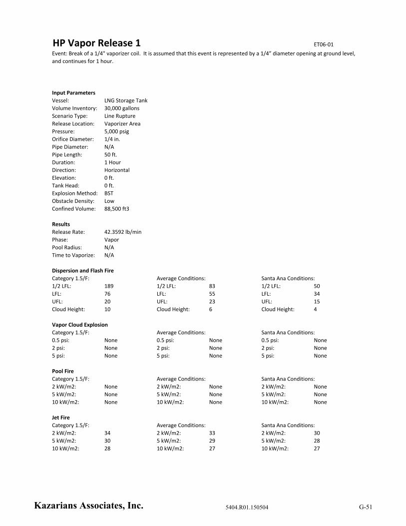
HP Vapor Release 1 ET06‐01
Input Parameters
Vessel: LNG Storage Tank
Volume Inventory: 30,000 gallons
Scenario Type: Line Rupture
Release Location: Vaporizer Area
Pressure: 5,000 psig
Orifice Diameter: 1/4 in.
Pipe Diameter: N/A
Pipe Length: 50 ft.
Duration: 1 Hour
Direction: Horizontal
Elevation: 0 ft.
Tank Head: 0 ft.
Explosion Method: BST
Obstacle Density: Low
Confined Volume: 88,500 ft3
Results
Release Rate: 42.3592 lb/min
Phase: Vapor
Pool Radius: N/A
Time to Vaporize: N/A
Dispersion and Flash Fire
1/2 LFL: 189 1/2 LFL: 83 1/2 LFL: 50
LFL: 76 LFL: 55 LFL: 34
UFL: 20 UFL: 23 UFL: 15
Cloud Height: 10 Cloud Height: 6 Cloud Height: 4
Vapor Cloud Explosion
Category 1.5/F: Average Conditions: Santa Ana Conditions:
0.5 psi: None 0.5 psi: None 0.5 psi: None
2 psi: None 2 psi: None 2 psi: None
5 psi: None 5 psi: None 5 psi: None
Pool Fire
Category 1.5/F: Average Conditions: Santa Ana Conditions:
2 kW/m2: None 2 kW/m2: None 2 kW/m2: None
5 kW/m2: None 5 kW/m2: None 5 kW/m2: None
10 kW/m2: None 10 kW/m2: None 10 kW/m2: None
Jet Fire
Category 1.5/F: Average Conditions: Santa Ana Conditions:
2 kW/m2: 34 2 kW/m2: 33 2 kW/m2: 30
5 kW/m2: 30 5 kW/m2: 29 5 kW/m2: 28
10 kW/m2: 28 10 kW/m2: 27 10 kW/m2: 27
Event: Break of a 1/4" vaporizer coil. It is assumed that this event is represented by a 1/4” diameter opening at ground level,
and continues for 1 hour.
Category 1.5/F: Average Conditions: Santa Ana Conditions:
Kazarians Associates, Inc. 5404.R01.150504 G-51
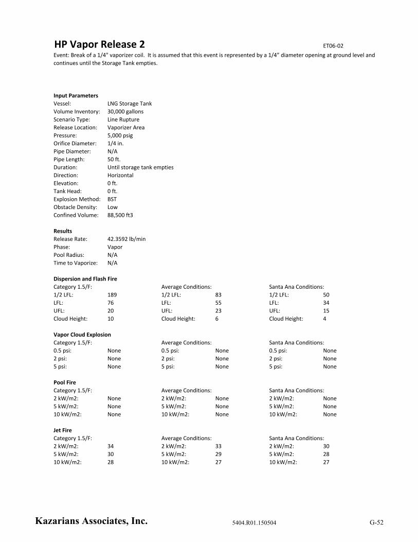
HP Vapor Release 2 ET06‐02
Input Parameters
Vessel: LNG Storage Tank
Volume Inventory: 30,000 gallons
Scenario Type: Line Rupture
Release Location: Vaporizer Area
Pressure: 5,000 psig
Orifice Diameter: 1/4 in.
Pipe Diameter: N/A
Pipe Length: 50 ft.
Duration: Until storage tank empties
Direction: Horizontal
Elevation: 0 ft.
Tank Head: 0 ft.
Explosion Method: BST
Obstacle Density: Low
Confined Volume: 88,500 ft3
Results
Release Rate: 42.3592 lb/min
Phase: Vapor
Pool Radius: N/A
Time to Vaporize: N/A
Dispersion and Flash Fire
1/2 LFL: 189 1/2 LFL: 83 1/2 LFL: 50
LFL: 76 LFL: 55 LFL: 34
UFL: 20 UFL: 23 UFL: 15
Cloud Height: 10 Cloud Height: 6 Cloud Height: 4
Vapor Cloud Explosion
Category 1.5/F: Average Conditions: Santa Ana Conditions:
0.5 psi: None 0.5 psi: None 0.5 psi: None
2 psi: None 2 psi: None 2 psi: None
5 psi: None 5 psi: None 5 psi: None
Pool Fire
Category 1.5/F: Average Conditions: Santa Ana Conditions:
2 kW/m2: None 2 kW/m2: None 2 kW/m2: None
5 kW/m2: None 5 kW/m2: None 5 kW/m2: None
10 kW/m2: None 10 kW/m2: None 10 kW/m2: None
Jet Fire
Category 1.5/F: Average Conditions: Santa Ana Conditions:
2 kW/m2: 34 2 kW/m2: 33 2 kW/m2: 30
5 kW/m2: 30 5 kW/m2: 29 5 kW/m2: 28
10 kW/m2: 28 10 kW/m2: 27 10 kW/m2: 27
Event: Break of a 1/4" vaporizer coil. It is assumed that this event is represented by a 1/4” diameter opening at ground level and
continues until the Storage Tank empties.
Category 1.5/F: Average Conditions: Santa Ana Conditions:
Kazarians Associates, Inc. 5404.R01.150504 G-52
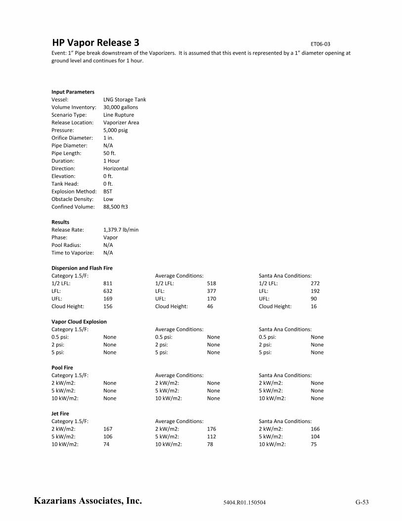
HP Vapor Release 3 ET06‐03
Input Parameters
Vessel: LNG Storage Tank
Volume Inventory: 30,000 gallons
Scenario Type: Line Rupture
Release Location: Vaporizer Area
Pressure: 5,000 psig
Orifice Diameter: 1 in.
Pipe Diameter: N/A
Pipe Length: 50 ft.
Duration: 1 Hour
Direction: Horizontal
Elevation: 0 ft.
Tank Head: 0 ft.
Explosion Method: BST
Obstacle Density: Low
Confined Volume: 88,500 ft3
Results
Release Rate: 1,379.7 lb/min
Phase: Vapor
Pool Radius: N/A
Time to Vaporize: N/A
Dispersion and Flash Fire
1/2 LFL: 811 1/2 LFL: 518 1/2 LFL: 272
LFL: 632 LFL: 377 LFL: 192
UFL: 169 UFL: 170 UFL: 90
Cloud Height: 156 Cloud Height: 46 Cloud Height: 16
Vapor Cloud Explosion
Category 1.5/F: Average Conditions: Santa Ana Conditions:
0.5 psi: None 0.5 psi: None 0.5 psi: None
2 psi: None 2 psi: None 2 psi: None
5 psi: None 5 psi: None 5 psi: None
Pool Fire
Category 1.5/F: Average Conditions: Santa Ana Conditions:
2 kW/m2: None 2 kW/m2: None 2 kW/m2: None
5 kW/m2: None 5 kW/m2: None 5 kW/m2: None
10 kW/m2: None 10 kW/m2: None 10 kW/m2: None
Jet Fire
Category 1.5/F: Average Conditions: Santa Ana Conditions:
2 kW/m2: 167 2 kW/m2: 176 2 kW/m2: 166
5 kW/m2: 106 5 kW/m2: 112 5 kW/m2: 104
10 kW/m2: 74 10 kW/m2: 78 10 kW/m2: 75
Event: 1” Pipe break downstream of the Vaporizers. It is assumed that this event is represented by a 1” diameter opening at
ground level and continues for 1 hour.
Category 1.5/F: Average Conditions: Santa Ana Conditions:
Kazarians Associates, Inc. 5404.R01.150504 G-53
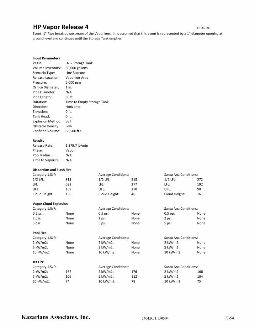
HP Vapor Release 4 ET06‐04
Input Parameters
Vessel: LNG Storage Tank
Volume Inventory: 30,000 gallons
Scenario Type: Line Rupture
Release Location: Vaporizer Area
Pressure: 5,000 psig
Orifice Diameter: 1 in.
Pipe Diameter: N/A
Pipe Length: 50 ft.
Duration: Time to Empty Storage Tank
Direction: Horizontal
Elevation: 0 ft.
Tank Head: 0 ft.
Explosion Method: BST
Obstacle Density: Low
Confined Volume: 88,500 ft3
Results
Release Rate: 1,379.7 lb/min
Phase: Vapor
Pool Radius: N/A
Time to Vaporize: N/A
Dispersion and Flash Fire
1/2 LFL: 811 1/2 LFL: 518 1/2 LFL: 272
LFL: 632 LFL: 377 LFL: 192
UFL: 169 UFL: 170 UFL: 90
Cloud Height: 156 Cloud Height: 46 Cloud Height: 16
Vapor Cloud Explosion
Category 1.5/F: Average Conditions: Santa Ana Conditions:
0.5 psi: None 0.5 psi: None 0.5 psi: None
2 psi: None 2 psi: None 2 psi: None
5 psi: None 5 psi: None 5 psi: None
Pool Fire
Category 1.5/F: Average Conditions: Santa Ana Conditions:
2 kW/m2: None 2 kW/m2: None 2 kW/m2: None
5 kW/m2: None 5 kW/m2: None 5 kW/m2: None
10 kW/m2: None 10 kW/m2: None 10 kW/m2: None
Jet Fire
Category 1.5/F: Average Conditions: Santa Ana Conditions:
2 kW/m2: 167 2 kW/m2: 176 2 kW/m2: 166
5 kW/m2: 106 5 kW/m2: 112 5 kW/m2: 104
10 kW/m2: 74 10 kW/m2: 78 10 kW/m2: 75
Event: 1” Pipe break downstream of the Vaporizers. It is assumed that this event is represented by a 1” diameter opening at
ground level and continues until the Storage Tank empties.
Category 1.5/F: Average Conditions: Santa Ana Conditions:
Kazarians Associates, Inc. 5404.R01.150504 G-54

HP Vapor Release 5 ET06‐12
Input Parameters
Vessel: LNG Storage Tank
Volume Inventory: 30,000 gallons
Scenario Type: Line Rupture
Release Location: Buffer Tank Area
Pressure: 4,200 psig
Orifice Diameter: 1 in.
Pipe Diameter: N/A
Pipe Length: 620 ft.
Duration: Time to Empty Storage Tank
Direction: Horizontal
Elevation: 0 ft.
Tank Head: 0 ft.
Explosion Method: BST
Obstacle Density: Low
Confined Volume: 1 m3
Results
Release Rate: 427.833 lb/min
Phase: Vapor
Pool Radius: N/A
Time to Vaporize: N/A
Dispersion and Flash Fire
1/2 LFL: 54 1/2 LFL: 246 1/2 LFL: 151
LFL: 48 LFL: 164 LFL: 104
UFL: 40 UFL: 70 UFL: 47
Cloud Height: 25 Cloud Height: 16 Cloud Height: 10
Vapor Cloud Explosion
Category 1.5/F: Average Conditions: Santa Ana Conditions:
0.5 psi: None 0.5 psi: None 0.5 psi: None
2 psi: None 2 psi: None 2 psi: None
5 psi: None 5 psi: None 5 psi: None
Pool Fire
Category 1.5/F: Average Conditions: Santa Ana Conditions:
2 kW/m2: None 2 kW/m2: None 2 kW/m2: None
5 kW/m2: None 5 kW/m2: None 5 kW/m2: None
10 kW/m2: None 10 kW/m2: None 10 kW/m2: None
Jet Fire
Category 1.5/F: Average Conditions: Santa Ana Conditions:
2 kW/m2: 121 2 kW/m2: 120 2 kW/m2: 114
5 kW/m2: 99 5 kW/m2: 99 5 kW/m2: 101
10 kW/m2: 87 10 kW/m2: 88 10 kW/m2: 95
Event: Damage to the CNG piping along the north wall of the facility due to mechanical impact. It is assumed that this event is
represented by a 1” diameter opening at ground level, and continues until the Storage Tank empties.
Category 1.5/F: Average Conditions: Santa Ana Conditions:
Kazarians Associates, Inc. 5404.R01.150504 G-55
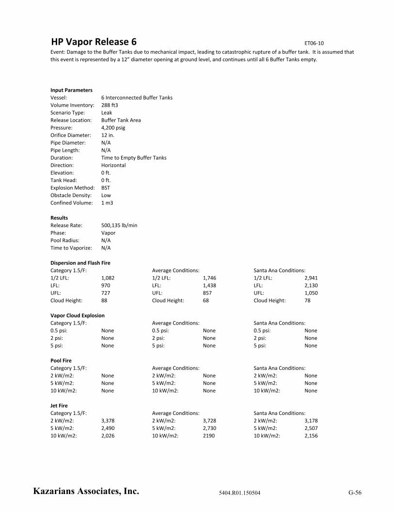
HP Vapor Release 6 ET06‐10
Input Parameters
Vessel: 6 Interconnected Buffer Tanks
Volume Inventory: 288 ft3
Scenario Type: Leak
Release Location: Buffer Tank Area
Pressure: 4,200 psig
Orifice Diameter: 12 in.
Pipe Diameter: N/A
Pipe Length: N/A
Duration: Time to Empty Buffer Tanks
Direction: Horizontal
Elevation: 0 ft.
Tank Head: 0 ft.
Explosion Method: BST
Obstacle Density: Low
Confined Volume: 1 m3
Results
Release Rate: 500,135 lb/min
Phase: Vapor
Pool Radius: N/A
Time to Vaporize: N/A
Dispersion and Flash Fire
1/2 LFL: 1,082 1/2 LFL: 1,746 1/2 LFL: 2,941
LFL: 970 LFL: 1,438 LFL: 2,130
UFL: 727 UFL: 857 UFL: 1,050
Cloud Height: 88 Cloud Height: 68 Cloud Height: 78
Vapor Cloud Explosion
Category 1.5/F: Average Conditions: Santa Ana Conditions:
0.5 psi: None 0.5 psi: None 0.5 psi: None
2 psi: None 2 psi: None 2 psi: None
5 psi: None 5 psi: None 5 psi: None
Pool Fire
Category 1.5/F: Average Conditions: Santa Ana Conditions:
2 kW/m2: None 2 kW/m2: None 2 kW/m2: None
5 kW/m2: None 5 kW/m2: None 5 kW/m2: None
10 kW/m2: None 10 kW/m2: None 10 kW/m2: None
Jet Fire
Category 1.5/F: Average Conditions: Santa Ana Conditions:
2 kW/m2: 3,378 2 kW/m2: 3,728 2 kW/m2: 3,178
5 kW/m2: 2,490 5 kW/m2: 2,730 5 kW/m2: 2,507
10 kW/m2: 2,026 10 kW/m2: 2190 10 kW/m2: 2,156
Event: Damage to the Buffer Tanks due to mechanical impact, leading to catastrophic rupture of a buffer tank. It is assumed that
this event is represented by a 12” diameter opening at ground level, and continues until all 6 Buffer Tanks empty.
Category 1.5/F: Average Conditions: Santa Ana Conditions:
Kazarians Associates, Inc. 5404.R01.150504 G-56

HP Vapor Release 7 ET06‐11
Input Parameters
Vessel: 6 Interconnected Buffer Tanks
Volume Inventory: 288 ft3
Scenario Type: Leak
Release Location: Buffer Tank Area
Pressure: 4,200 psig
Orifice Diameter: 2 in.
Pipe Diameter: N/A
Pipe Length: N/A
Duration: Time to Empty Buffer Tanks
Direction: Horizontal
Elevation: 0 ft.
Tank Head: 0 ft.
Explosion Method: BST
Obstacle Density: Low
Confined Volume: 1 m3
Results
Release Rate: 13,892.6 lb/min
Phase: Vapor
Pool Radius: N/A
Time to Vaporize: N/A
Dispersion and Flash Fire
1/2 LFL: 228 1/2 LFL: 1,610 1/2 LFL: 890
LFL: 207 LFL: 1,104 LFL: 615
UFL: 173 UFL: 403 UFL: 269
Cloud Height: 72 Cloud Height: 53 Cloud Height: 44
Vapor Cloud Explosion
Category 1.5/F: Average Conditions: Santa Ana Conditions:
0.5 psi: None 0.5 psi: None 0.5 psi: None
2 psi: None 2 psi: None 2 psi: None
5 psi: None 5 psi: None 5 psi: None
Pool Fire
Category 1.5/F: Average Conditions: Santa Ana Conditions:
2 kW/m2: None 2 kW/m2: None 2 kW/m2: None
5 kW/m2: None 5 kW/m2: None 5 kW/m2: None
10 kW/m2: None 10 kW/m2: None 10 kW/m2: None
Jet Fire
Category 1.5/F: Average Conditions: Santa Ana Conditions:
2 kW/m2: 664 2 kW/m2: 688 2 kW/m2: 620
5 kW/m2: 504 5 kW/m2: 524 5 kW/m2: 492
10 kW/m2: 416 10 kW/m2: 436 10 kW/m2: 444
Event: Damage to the Buffer Tanks due to mechanical impact, resulting in a puncture of one Tank. It is assumed that this event
is represented by a 2” diameter opening at ground level, and continues until all 6 Buffer Tanks empty.
Category 1.5/F: Average Conditions: Santa Ana Conditions:
Kazarians Associates, Inc. 5404.R01.150504 G-57

HP Vapor Release 8 ET05‐01
Input Parameters
Vessel: 6 Interconnected Buffer Tanks
Volume Inventory: 288 ft3
Scenario Type: Leak
Release Location: Buffer Tank Area
Pressure: 11,000 psig
Orifice Diameter: 12 in.
Pipe Diameter: N/A
Pipe Length: N/A
Duration: Time to Empty Buffer Tanks
Direction: Horizontal
Elevation: 0 ft.
Tank Head: 0 ft.
Explosion Method: BST
Obstacle Density: Low
Confined Volume: 1 m3
Results
Release Rate: 1,102,800 lb/min
Phase: Vapor
Pool Radius: N/A
Time to Vaporize: N/A
Dispersion and Flash Fire
1/2 LFL: 1,506 1/2 LFL: 2,152 1/2 LFL: 3,620
LFL: 1,346 LFL: 1,791 LFL: 2,622
UFL: 918 UFL: 1,019 UFL: 1,256
Cloud Height: 98 Cloud Height: 86 Cloud Height: 90
Vapor Cloud Explosion
Category 1.5/F: Average Conditions: Santa Ana Conditions:
0.5 psi: None 0.5 psi: None 0.5 psi: None
2 psi: None 2 psi: None 2 psi: None
5 psi: None 5 psi: None 5 psi: None
Pool Fire
Category 1.5/F: Average Conditions: Santa Ana Conditions:
2 kW/m2: None 2 kW/m2: None 2 kW/m2: None
5 kW/m2: None 5 kW/m2: None 5 kW/m2: None
10 kW/m2: None 10 kW/m2: None 10 kW/m2: None
Jet Fire
Category 1.5/F: Average Conditions: Santa Ana Conditions:
2 kW/m2: 4,773 2 kW/m2: 5,332 2 kW/m2: 4,668
5 kW/m2: 3,524 5 kW/m2: 3,902 5 kW/m2: 3,653
10 kW/m2: 2,918 10 kW/m2: 3,124 10 kW/m2: 3,117
Event: Catastrophic failure of a Buffer Tank due to increased pressure from an external fire. It is assumed that this event is
represented by a 12” diameter opening at ground level at 11,000 psi, and continues until all 6 Buffer Tanks empty.
Category 1.5/F: Average Conditions: Santa Ana Conditions:
Kazarians Associates, Inc. 5404.R01.150504 G-58

Buffer PSV Lift 1 ET01‐02
Input Parameters
Vessel: LNG Storage Tank
Volume Inventory: 30,000 gallons
Scenario Type: Relief Valve
Release Location: Buffer Tank Area
Pressure: 5,500 psig
Orifice Diameter: 3/4 in.
Pipe Diameter: 1 in.
Pipe Length: 10 ft.
Duration: Time to Empty Storage Tank
Direction: Vertical
Elevation: 10 ft.
Tank Head: 0 ft.
Explosion Method: BST
Obstacle Density: Low
Confined Volume: 1 m3
Results
Release Rate: 2,669 lb/min
Phase: Vapor
Pool Radius: N/A
Time to Vaporize: N/A
Dispersion and Flash Fire
1/2 LFL: 19 1/2 LFL: 21 1/2 LFL: 23
LFL: 8 LFL: 9 LFL: 10
UFL: 2 UFL: 2 UFL: 2
Cloud Height: 123 Cloud Height: 95 Cloud Height: 55
Vapor Cloud Explosion
Category 1.5/F: Average Conditions: Santa Ana Conditions:
0.5 psi: None 0.5 psi: None 0.5 psi: None
2 psi: None 2 psi: None 2 psi: None
5 psi: None 5 psi: None 5 psi: None
Pool Fire
Category 1.5/F: Average Conditions: Santa Ana Conditions:
2 kW/m2: None 2 kW/m2: None 2 kW/m2: None
5 kW/m2: None 5 kW/m2: None 5 kW/m2: None
10 kW/m2: None 10 kW/m2: None 10 kW/m2: None
Jet Fire
Category 1.5/F: Average Conditions: Santa Ana Conditions:
2 kW/m2: 184 2 kW/m2: 226 2 kW/m2: 235
5 kW/m2: 63 5 kW/m2: 126 5 kW/m2: 152
10 kW/m2: None 10 kW/m2: 51 10 kW/m2: 108
Event: Failure of the Priority Panel, sending CNG to full Buffer Tanks, resulting in lifting of the Buffer Tank PSVs. It is assumed
that this event is represented by a 1/4” diameter opening at 10 ft. elevation, and continues until the Storage Tank empties.
Category 1.5/F: Average Conditions: Santa Ana Conditions:
Kazarians Associates, Inc. 5404.R01.150504 G-59

Buffer PSV Lift 2 ET01‐01
Input Parameters
Vessel: 6 Interconnected Buffer Tanks
Volume Inventory: 288 ft3
Scenario Type: Relief Valve
Release Location: Buffer Tank Area
Pressure: 4,200 psig
Orifice Diameter: 3/4 in.
Pipe Diameter: 1 in.
Pipe Length: 10 ft.
Duration: Time to Empty Storage Tank
Direction: Vertical
Elevation: 10 ft.
Tank Head: 0 ft.
Explosion Method: BST
Obstacle Density: Low
Confined Volume: 1 m3
Results
Release Rate: 1,944.28 lb/min
Phase: Vapor
Pool Radius: N/A
Time to Vaporize: N/A
Dispersion and Flash Fire
1/2 LFL: 17 1/2 LFL: 17 1/2 LFL: 19
LFL: 7 LFL: 7 LFL: 8
UFL: 2 UFL: 2 UFL: 2
Cloud Height: 109 Cloud Height: 83 Cloud Height: 49
Vapor Cloud Explosion
Category 1.5/F: Average Conditions: Santa Ana Conditions:
0.5 psi: None 0.5 psi: None 0.5 psi: None
2 psi: None 2 psi: None 2 psi: None
5 psi: None 5 psi: None 5 psi: None
Pool Fire
Category 1.5/F: Average Conditions: Santa Ana Conditions:
2 kW/m2: None 2 kW/m2: None 2 kW/m2: None
5 kW/m2: None 5 kW/m2: None 5 kW/m2: None
10 kW/m2: None 10 kW/m2: None 10 kW/m2: None
Jet Fire
Category 1.5/F: Average Conditions: Santa Ana Conditions:
2 kW/m2: 157 2 kW/m2: 194 2 kW/m2: 203
5 kW/m2: 44 5 kW/m2: 106 5 kW/m2: 130
10 kW/m2: None 10 kW/m2: 37 10 kW/m2: 93
Event: Spurious lift of a PSV on a Buffer Tank. It is assumed that this event is represented by a 3/4” diameter opening at 10 ft.
elevation and continues until all Buffer Tanks empty.
Category 1.5/F: Average Conditions: Santa Ana Conditions:
Kazarians Associates, Inc. 5404.R01.150504 G-60
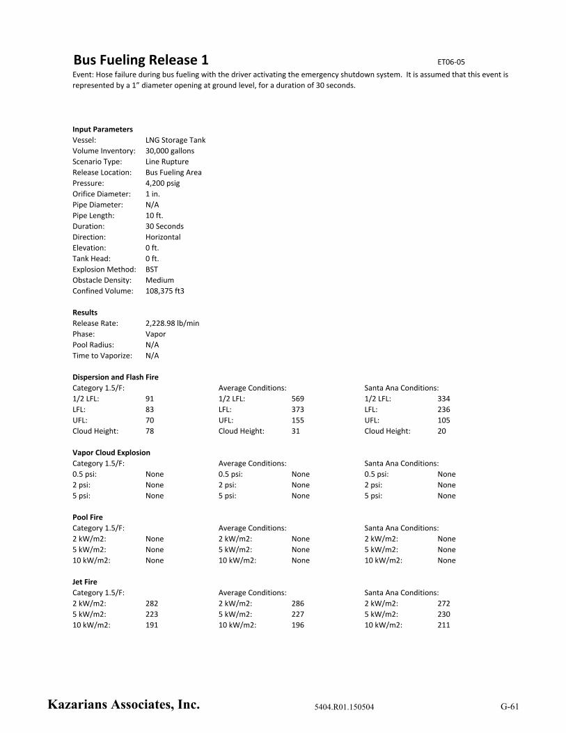
Bus Fueling Release 1 ET06‐05
Input Parameters
Vessel: LNG Storage Tank
Volume Inventory: 30,000 gallons
Scenario Type: Line Rupture
Release Location: Bus Fueling Area
Pressure: 4,200 psig
Orifice Diameter: 1 in.
Pipe Diameter: N/A
Pipe Length: 10 ft.
Duration: 30 Seconds
Direction: Horizontal
Elevation: 0 ft.
Tank Head: 0 ft.
Explosion Method: BST
Obstacle Density: Medium
Confined Volume: 108,375 ft3
Results
Release Rate: 2,228.98 lb/min
Phase: Vapor
Pool Radius: N/A
Time to Vaporize: N/A
Dispersion and Flash Fire
1/2 LFL: 91 1/2 LFL: 569 1/2 LFL: 334
LFL: 83 LFL: 373 LFL: 236
UFL: 70 UFL: 155 UFL: 105
Cloud Height: 78 Cloud Height: 31 Cloud Height: 20
Vapor Cloud Explosion
Category 1.5/F: Average Conditions: Santa Ana Conditions:
0.5 psi: None 0.5 psi: None 0.5 psi: None
2 psi: None 2 psi: None 2 psi: None
5 psi: None 5 psi: None 5 psi: None
Pool Fire
Category 1.5/F: Average Conditions: Santa Ana Conditions:
2 kW/m2: None 2 kW/m2: None 2 kW/m2: None
5 kW/m2: None 5 kW/m2: None 5 kW/m2: None
10 kW/m2: None 10 kW/m2: None 10 kW/m2: None
Jet Fire
Category 1.5/F: Average Conditions: Santa Ana Conditions:
2 kW/m2: 282 2 kW/m2: 286 2 kW/m2: 272
5 kW/m2: 223 5 kW/m2: 227 5 kW/m2: 230
10 kW/m2: 191 10 kW/m2: 196 10 kW/m2: 211
Event: Hose failure during bus fueling with the driver activating the emergency shutdown system. It is assumed that this event is
represented by a 1” diameter opening at ground level, for a duration of 30 seconds.
Category 1.5/F: Average Conditions: Santa Ana Conditions:
Kazarians Associates, Inc. 5404.R01.150504 G-61

Bus Fueling Release 2 ET06‐06
Input Parameters
Vessel: LNG Storage Tank
Volume Inventory: 30,000 gallons
Scenario Type: Line Rupture
Release Location: Bus Fueling Area
Pressure: 4,200 psig
Orifice Diameter: 1 in.
Pipe Diameter: N/A
Pipe Length: 10 ft.
Duration: Time to Empty Storage Tank
Direction: Horizontal
Elevation: 0 ft.
Tank Head: 0 ft.
Explosion Method: BST
Obstacle Density: Medium
Confined Volume: 108,375 ft3
Results
Release Rate: 2,228.98 lb/min
Phase: Vapor
Pool Radius: N/A
Time to Vaporize: N/A
Dispersion and Flash Fire
1/2 LFL: 91 1/2 LFL: 569 1/2 LFL: 334
LFL: 83 LFL: 373 LFL: 236
UFL: 70 UFL: 155 UFL: 105
Cloud Height: 78 Cloud Height: 31 Cloud Height: 20
Vapor Cloud Explosion
Category 1.5/F: Average Conditions: Santa Ana Conditions:
0.5 psi: None 0.5 psi: None 0.5 psi: None
2 psi: None 2 psi: None 2 psi: None
5 psi: None 5 psi: None 5 psi: None
Pool Fire
Category 1.5/F: Average Conditions: Santa Ana Conditions:
2 kW/m2: None 2 kW/m2: None 2 kW/m2: None
5 kW/m2: None 5 kW/m2: None 5 kW/m2: None
10 kW/m2: None 10 kW/m2: None 10 kW/m2: None
Jet Fire
Category 1.5/F: Average Conditions: Santa Ana Conditions:
2 kW/m2: 282 2 kW/m2: 286 2 kW/m2: 272
5 kW/m2: 223 5 kW/m2: 227 5 kW/m2: 230
10 kW/m2: 191 10 kW/m2: 196 10 kW/m2: 211
Event: Hose failure during bus fueling with the driver not activating the emergency shutdown system. It is assumed that this
event is represented by a 1” diameter opening at ground level, and continues until the Storage Tank empties.
Category 1.5/F: Average Conditions: Santa Ana Conditions:
Kazarians Associates, Inc. 5404.R01.150504 G-62
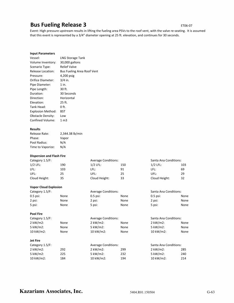
Bus Fueling Release 3 ET06‐07
Input Parameters
Vessel: LNG Storage Tank
Volume Inventory: 30,000 gallons
Scenario Type: Relief Valve
Release Location: Bus Fueling Area Roof Vent
Pressure: 4,200 psig
Orifice Diameter: 3/4 in.
Pipe Diameter: 1 in.
Pipe Length: 30 ft.
Duration: 30 Seconds
Direction: Horizontal
Elevation: 25 ft.
Tank Head: 0 ft.
Explosion Method: BST
Obstacle Density: Low
Confined Volume: 1 m3
Results
Release Rate: 2,344.38 lb/min
Phase: Vapor
Pool Radius: N/A
Time to Vaporize: N/A
Dispersion and Flash Fire
1/2 LFL: 190 1/2 LFL: 150 1/2 LFL: 103
LFL: 103 LFL: 91 LFL: 69
UFL: 25 UFL: 25 UFL: 29
Cloud Height: 35 Cloud Height: 33 Cloud Height: 32
Vapor Cloud Explosion
Category 1.5/F: Average Conditions: Santa Ana Conditions:
0.5 psi: None 0.5 psi: None 0.5 psi: None
2 psi: None 2 psi: None 2 psi: None
5 psi: None 5 psi: None 5 psi: None
Pool Fire
Category 1.5/F: Average Conditions: Santa Ana Conditions:
2 kW/m2: None 2 kW/m2: None 2 kW/m2: None
5 kW/m2: None 5 kW/m2: None 5 kW/m2: None
10 kW/m2: None 10 kW/m2: None 10 kW/m2: None
Jet Fire
Category 1.5/F: Average Conditions: Santa Ana Conditions:
2 kW/m2: 292 2 kW/m2: 299 2 kW/m2: 285
5 kW/m2: 225 5 kW/m2: 232 5 kW/m2: 240
10 kW/m2: 184 10 kW/m2: 194 10 kW/m2: 214
Event: High pressure upstream results in lifting the fueling area PSVs to the roof vent, with the valve re‐seating. It is assumed
that this event is represented by a 3/4” diameter opening at 25 ft. elevation, and continues for 30 seconds.
Category 1.5/F: Average Conditions: Santa Ana Conditions:
Kazarians Associates, Inc. 5404.R01.150504 G-63

Bus Fueling Release 4 ET06‐08
Input Parameters
Vessel: LNG Storage Tank
Volume Inventory: 30,000 gallons
Scenario Type: Relief Valve
Release Location: Bus Fueling Area Roof Vent
Pressure: 4,200 psig
Orifice Diameter: 3/4 in.
Pipe Diameter: 1 in.
Pipe Length: 30 ft.
Duration: Time to Empty Storage Tank
Direction: Horizontal
Elevation: 25 ft.
Tank Head: 0 ft.
Explosion Method: BST
Obstacle Density: Low
Confined Volume: 1 m3
Results
Release Rate: 2,344.38 lb/min
Phase: Vapor
Pool Radius: N/A
Time to Vaporize: N/A
Dispersion and Flash Fire
1/2 LFL: 190 1/2 LFL: 150 1/2 LFL: 103
LFL: 103 LFL: 91 LFL: 69
UFL: 25 UFL: 25 UFL: 29
Cloud Height: 35 Cloud Height: 33 Cloud Height: 32
Vapor Cloud Explosion
Category 1.5/F: Average Conditions: Santa Ana Conditions:
0.5 psi: None 0.5 psi: None 0.5 psi: None
2 psi: None 2 psi: None 2 psi: None
5 psi: None 5 psi: None 5 psi: None
Pool Fire
Category 1.5/F: Average Conditions: Santa Ana Conditions:
2 kW/m2: None 2 kW/m2: None 2 kW/m2: None
5 kW/m2: None 5 kW/m2: None 5 kW/m2: None
10 kW/m2: None 10 kW/m2: None 10 kW/m2: None
Jet Fire
Category 1.5/F: Average Conditions: Santa Ana Conditions:
2 kW/m2: 292 2 kW/m2: 299 2 kW/m2: 285
5 kW/m2: 225 5 kW/m2: 232 5 kW/m2: 240
10 kW/m2: 184 10 kW/m2: 194 10 kW/m2: 214
Event: High pressure upstream results in lifting the fueling are PSVs to the roof vent, and the valve fails to re‐seat. It is assumed
that this event is represented by a 3/4” diameter opening at 25 ft. elevation, and continues until the Storage Tank empties.
Category 1.5/F: Average Conditions: Santa Ana Conditions:
Kazarians Associates, Inc. 5404.R01.150504 G-64

Bus Fueling Release 5 ET06‐09
Input Parameters
Vessel: LNG Storage Tank
Volume Inventory: 30,000 gallons
Scenario Type: Relief Valve
Release Location: Bus Fueling Area Roof Vent
Pressure: 4,200 psig
Orifice Diameter: 3/4 in.
Pipe Diameter: 1 in.
Pipe Length: 30 ft.
Duration: Time to Empty Storage Tank
Direction: Horizontal
Elevation: 25 ft.
Tank Head: 0 ft.
Explosion Method: BST
Obstacle Density: Low
Confined Volume: 1 m3
Results
Release Rate: 2,344.38 lb/min
Phase: Vapor
Pool Radius: N/A
Time to Vaporize: N/A
Dispersion and Flash Fire
1/2 LFL: 190 1/2 LFL: 150 1/2 LFL: 103
LFL: 103 LFL: 91 LFL: 69
UFL: 25 UFL: 25 UFL: 29
Cloud Height: 35 Cloud Height: 33 Cloud Height: 32
Vapor Cloud Explosion
Category 1.5/F: Average Conditions: Santa Ana Conditions:
0.5 psi: None 0.5 psi: None 0.5 psi: None
2 psi: None 2 psi: None 2 psi: None
5 psi: None 5 psi: None 5 psi: None
Pool Fire
Category 1.5/F: Average Conditions: Santa Ana Conditions:
2 kW/m2: None 2 kW/m2: None 2 kW/m2: None
5 kW/m2: None 5 kW/m2: None 5 kW/m2: None
10 kW/m2: None 10 kW/m2: None 10 kW/m2: None
Jet Fire
Category 1.5/F: Average Conditions: Santa Ana Conditions:
2 kW/m2: 292 2 kW/m2: 299 2 kW/m2: 285
5 kW/m2: 225 5 kW/m2: 232 5 kW/m2: 240
10 kW/m2: 184 10 kW/m2: 194 10 kW/m2: 214
Event: Spurious lift of the PSV on a Bus Fueling Station. It is assumed that this event is represented by a 3/4” diameter opening
at 25 ft. elevation and continues until the Storage Tank empties.
Category 1.5/F: Average Conditions: Santa Ana Conditions:
Kazarians Associates, Inc. 5404.R01.150504 G-65

Appendix H – Event Trees
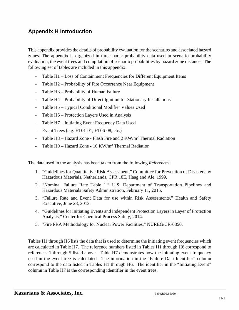
Kazarians & Associates, Inc. 5404.R01.150504
Appendix H Introduction
This appendix provides the details of probability evaluation for the scenarios and associated hazard zones. The appendix is organized in three parts: probability data used in scenario probability evaluation, the event trees and compilation of scenario probabilities by hazard zone distance. The following set of tables are included in this appendix:
- Table H1 – Loss of Containment Frequencies for Different Equipment Items
- Table H2 – Probability of Fire Occurrence Near Equipment
- Table H3 – Probability of Human Failure
- Table H4 – Probability of Direct Ignition for Stationary Installations
- Table H5 – Typical Conditional Modifier Values Used
- Table H6 – Protection Layers Used in Analysis
- Table H7 – Initiating Event Frequency Data Used
- Event Trees (e.g. ET01-01, ET06-08, etc.)
- Table H8 – Hazard Zone - Flash Fire and 2 KW/m2 Thermal Radiation
- Table H9 – Hazard Zone - 10 KW/m2 Thermal Radiation
The data used in the analysis has been taken from the following References:
1. “Guidelines for Quantitative Risk Assessment,” Committee for Prevention of Disasters by Hazardous Materials, Netherlands, CPR 18E, Haag and Ale, 1999.
2. “Nominal Failure Rate Table 1,” U.S. Department of Transportation Pipelines and Hazardous Materials Safety Administration, February 11, 2015.
3. “Failure Rate and Event Data for use within Risk Assessments,” Health and Safety Executive, June 28, 2012.
4. “Guidelines for Initiating Events and Independent Protection Layers in Layer of Protection Analysis,” Center for Chemical Process Safety, 2014.
5. "Fire PRA Methodology for Nuclear Power Facilities," NUREG/CR-6850.
Tables H1 through H6 lists the data that is used to determine the initiating event frequencies which are calculated in Table H7. The reference numbers listed in Tables H1 through H6 correspond to references 1 through 5 listed above. Table H7 demonstrates how the initiating event frequency used in the event tree is calculated. The information in the “Failure Data Identifier” column correspond to the data listed in Tables H1 through H6. The identifier in the “Initiating Event” column in Table H7 is the corresponding identifier in the event trees.
H-1
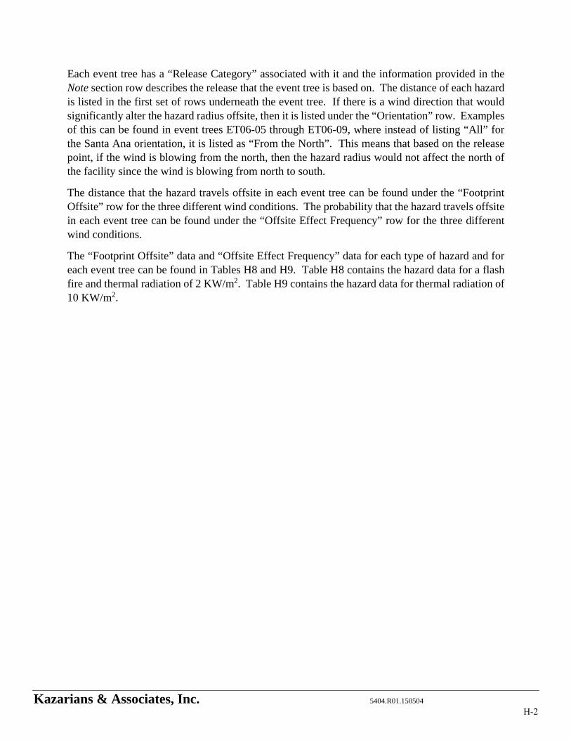
Kazarians & Associates, Inc. 5404.R01.150504
Each event tree has a “Release Category” associated with it and the information provided in the Note section row describes the release that the event tree is based on. The distance of each hazard is listed in the first set of rows underneath the event tree. If there is a wind direction that would significantly alter the hazard radius offsite, then it is listed under the “Orientation” row. Examples of this can be found in event trees ET06-05 through ET06-09, where instead of listing “All” for the Santa Ana orientation, it is listed as “From the North”. This means that based on the release point, if the wind is blowing from the north, then the hazard radius would not affect the north of the facility since the wind is blowing from north to south.
The distance that the hazard travels offsite in each event tree can be found under the “Footprint Offsite” row for the three different wind conditions. The probability that the hazard travels offsite in each event tree can be found under the “Offsite Effect Frequency” row for the three different wind conditions.
The “Footprint Offsite” data and “Offsite Effect Frequency” data for each type of hazard and for each event tree can be found in Tables H8 and H9. Table H8 contains the hazard data for a flash fire and thermal radiation of 2 KW/m2. Table H9 contains the hazard data for thermal radiation of 10 KW/m2.
H-2
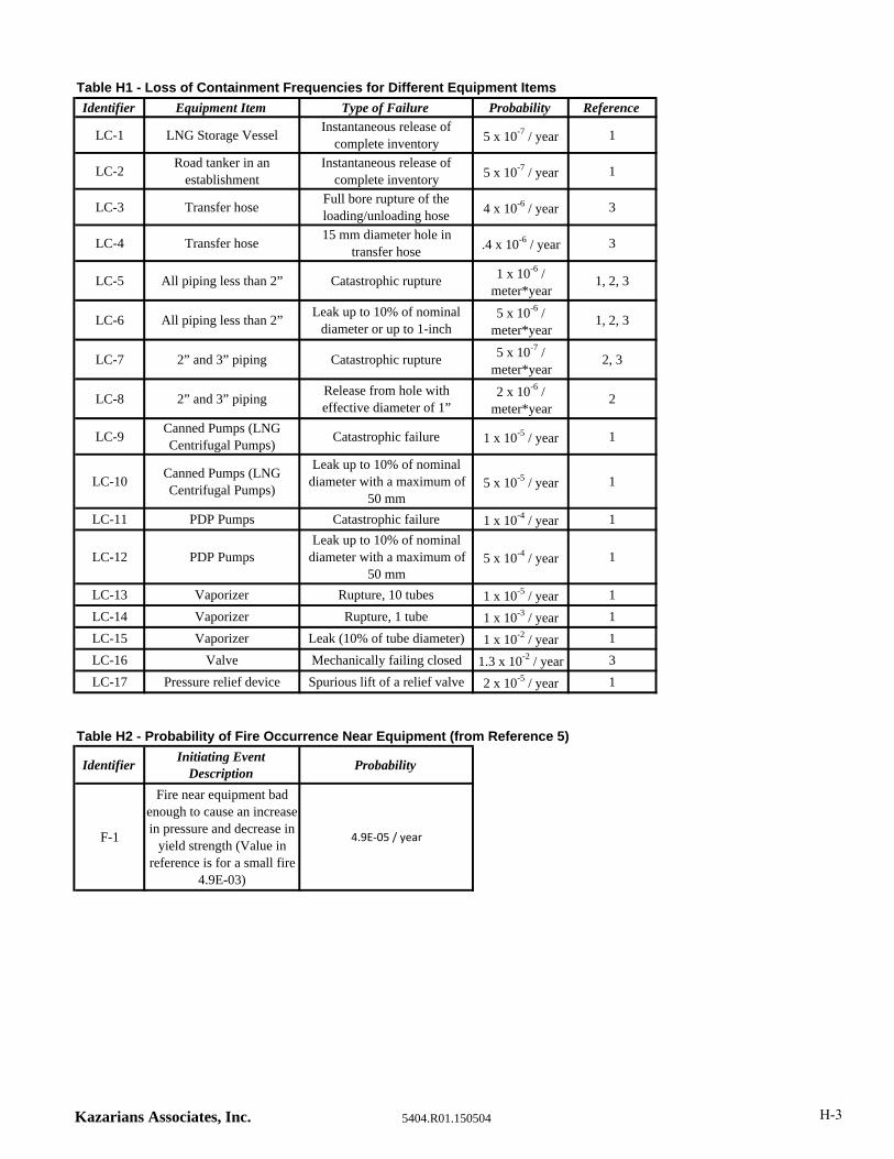
Table H1 - Loss of Containment Frequencies for Different Equipment Items
Identifier Equipment Item Type of Failure Probability Reference
LC-1 LNG Storage VesselInstantaneous release of
complete inventory 5 x 10⁻⁷ / year 1
LC-2Road tanker in an
establishmentInstantaneous release of
complete inventory 5 x 10⁻⁷ / year 1
LC-3 Transfer hoseFull bore rupture of the loading/unloading hose 4 x 10⁻⁶ / year 3
LC-4 Transfer hose15 mm diameter hole in
transfer hose .4 x 10-6 / year 3
LC-5 All piping less than 2” Catastrophic rupture 1 x 10⁻⁶ / meter*year
1, 2, 3
LC-6 All piping less than 2”Leak up to 10% of nominal
diameter or up to 1-inch5 x 10-6 /
meter*year1, 2, 3
LC-7 2” and 3” piping Catastrophic rupture 5 x 10⁻⁷ / meter*year
2, 3
LC-8 2” and 3” pipingRelease from hole with effective diameter of 1”
2 x 10⁻⁶ / meter*year
2
LC-9Canned Pumps (LNG Centrifugal Pumps)
Catastrophic failure 1 x 10⁻⁵ / year 1
LC-10Canned Pumps (LNG Centrifugal Pumps)
Leak up to 10% of nominal diameter with a maximum of
50 mm5 x 10-5 / year 1
LC-11 PDP Pumps Catastrophic failure 1 x 10⁻⁴ / year 1
LC-12 PDP PumpsLeak up to 10% of nominal
diameter with a maximum of 50 mm
5 x 10⁻⁴ / year 1
LC-13 Vaporizer Rupture, 10 tubes 1 x 10⁻⁵ / year 1
LC-14 Vaporizer Rupture, 1 tube 1 x 10⁻³ / year 1
LC-15 Vaporizer Leak (10% of tube diameter) 1 x 10⁻² / year 1
LC-16 Valve Mechanically failing closed 1.3 x 10⁻² / year 3
LC-17 Pressure relief device Spurious lift of a relief valve 2 x 10⁻⁵ / year 1
Table H2 - Probability of Fire Occurrence Near Equipment (from Reference 5)
IdentifierInitiating Event
DescriptionProbability
F-1
Fire near equipment bad enough to cause an increase in pressure and decrease in
yield strength (Value in reference is for a small fire
4.9E-03)
4.9E‐05 / year
Kazarians Associates, Inc. 5404.R01.150504 H-3
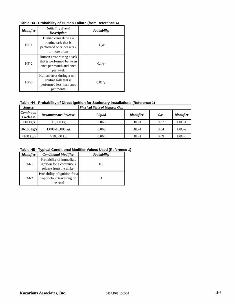
Table H3 - Probability of Human Failure (from Reference 4)
IdentifierInitiating Event
DescriptionProbability
HF-1
Human error during a routine task that is
performed once per week or more often
1/yr
HF-2
Human error during a task that is performed between once per month and once
per week
0.1/yr
HF-3
Human error during a non-routine task that is
performed less than once per month
0.01/yr
Table H4 - Probability of Direct Ignition for Stationary Installations (Reference 1)Source Physical State of Natural Gas
Continuous Release
Instantaneous Release Liquid Identifier Gas Identifier
<10 kg/s <1,000 kg 0.065 DIL-1 0.02 DIG-1
10-100 kg/s 1,000-10,000 kg 0.065 DIL-1 0.04 DIG-2
>100 kg/s >10,000 kg 0.065 DIL-1 0.09 DIG-3
Table H5 - Typical Conditional Modifier Values Used (Reference 1)Identifier Conditional Modifier Probability
CM-1Probability of immediate ignition for a continuous release from the tanker
0.1
CM-2Probability of ignition for a vapor cloud travelling on
the road1
Kazarians Associates, Inc. 5404.R01.150504 H-4
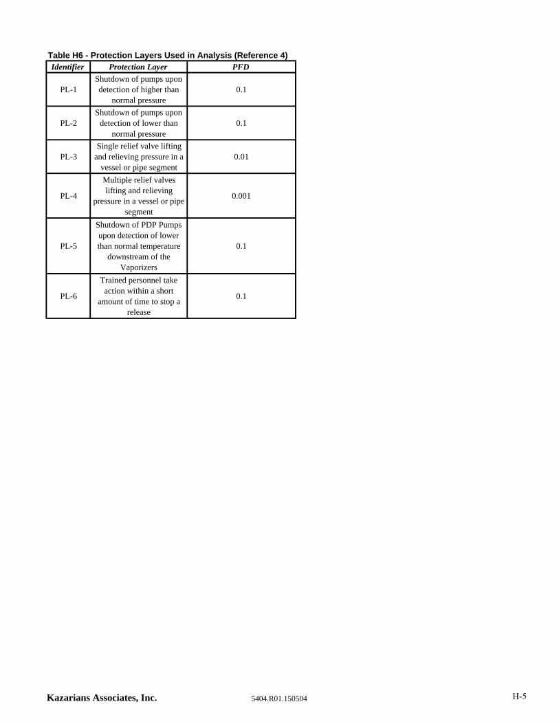
Table H6 - Protection Layers Used in Analysis (Reference 4)Identifier Protection Layer PFD
PL-1Shutdown of pumps upon detection of higher than
normal pressure0.1
PL-2Shutdown of pumps upon
detection of lower than normal pressure
0.1
PL-3Single relief valve lifting
and relieving pressure in a vessel or pipe segment
0.01
PL-4
Multiple relief valves lifting and relieving
pressure in a vessel or pipe segment
0.001
PL-5
Shutdown of PDP Pumps upon detection of lower than normal temperature
downstream of the Vaporizers
0.1
PL-6
Trained personnel take action within a short
amount of time to stop a release
0.1
Kazarians Associates, Inc. 5404.R01.150504 H-5

Table H7 - Initiating Event Frequency Data UsedInitiating Event Frequency Description Failure Data Identifier
BFL 4.90E‐05Buffer Tank relief valve lift due to external fire nearby, (4.9E‐
05)F‐1
BFR 4.90E‐08
Buffer Tank rupture due to external fire nearby, multiple
relief valves fail to lift and prevent overpressure (4.9E‐
05*0.001)
F‐1 (4.9E‐05)
PL‐4 (1E‐03)
FFEF 1.30E‐05
Failure of fan resulting in liquid sent to priority panel and
low temperature embrittlement. Fan failure (0.013), failure
of low temperature shutdown to activate (0.1), LNG does
not vaporize in fan tubes based on ambient temperature
(0.1), liquid travels through CNG piping and does not
vaporize (0.1). (.013*.1*.1*.1=1.3E‐05)
LC‐16 (1.3E‐02)
PL‐5 (0.1)
Based on system design
(0.1)
Based on system design
(0.1)
FLRM 9.50E‐01 Flame does not flash back to roomBased on storage room
design
HB‐1 3.60E‐06Loading hose breaks and operator activates emergency stop
(.000004*.9=3.6E‐06)
LC‐3 (4E‐06)
PL‐6 (.9)
HB‐2 4.00E‐07Loading hose breaks and operator does not activate
emergency stop (.000004*.1)
LC‐3 (4E‐06)
PL‐6 (.1)
HED 1.00E‐05Personnel error in opening a drain valve on a full storage
tank and unable to close it immediately
Based on personnel
training and fact that drain
valve is never used
HEO 1.00E‐04Vendor error resulting in overfill of a storage tank or liquid
release from vent and vendor does not shutdown system
Based on personnel
training and awareness
during delivery process
HERFDL‐01 1.00E‐05
Block valves left closed (0.01), high pressure shutdown does
not work (0.1), and relief valve fails to lift (0.01).
(0.01*0.01*0.1=0.00001)
HF‐3 (0.01)
PL‐1 (0.1)
PL‐3 (0.01)
HERFDL‐02 1.30E‐06
Control valve fails closed (0.013), high pressure shutdown
does not work (0.1), and multiple relief valves fail to lift
(0.013*.001*.1=0.0000013)
LC‐16 (1.3E‐03)
PL‐1 (0.1)
PL‐4 (1E‐03)
HERFDL‐03 1.00E‐06
Block valve left closed (0.01) ,high pressure shutdown does
not work (0.1), and multiple relief valves fail to lift
(0.01*.001*.1=0.000001)
HF‐3 (0.01)
PL‐1 (0.1)
PL‐4 (1E‐03)
IC‐03‐01 1.30E‐06
Initiating Cause for Event Tree 03‐01. ROV‐400 or ROV‐410
fail closed (.013), and multiple relief valves fail to lift (1E‐
03), high pressure shutdown does not work (0.1), and
relieve pressure (0.013*.001*0.1=1.3E‐06)
LC‐16 (1.3E‐03)
PL‐1 (0.1)
PL‐4 (1E‐03)
IIGN‐01 9.35E‐01
No Ignition Inside the room. Probability of direct ignition
for liquid release for stationary installation from "Purple
Book" is 0.065
DIL‐1
IIGN‐02 9.80E‐01Probability of No Direct Ignition for a continuous release
less than 10 kg/sDIG‐1
Kazarians Associates, Inc. 5404.R01.150504 H-6

Table H7 - Initiating Event Frequency Data UsedInitiating Event Frequency Description Failure Data Identifier
IIGN‐03 9.60E‐01Probability of No Direct Ignition for a continuous release
between 10 kg/s and 100 kg/sDIG‐2
IIGN‐04 9.10E‐01Probability of No Direct Ignition for a continuous release
greater than 100 kg/sDIG‐3
IIGN‐06 5.00E‐01
Probability of No Direct Ignition for a release from a Buffer
Tank due to increase pressure due to an external fire
nearby
Based on fire near a release
MI‐01 1.00E‐06Mechanical impact to Buffer Tank or CNG piping leading to
rupture
Based on protection
around equipment
MI‐02 2.00E‐06 Mechanical impact to Buffer Tank leading to 2" leakBased on protection
around equipment
MLSN‐1 1.00E‐05
Priority panel malfunction (.001) resulting in high pressure
to the Buffer Tanks or Fueling Station, and high pressure
shutdown does not work (0.1) and personnel do not
shutdown system (0.1). (.001*.1*.1=1E‐05)
Based on Priority Panel
reliability (0.001)
PL‐1 (0.1)
PL‐6 (0.1)
MLSN‐2 9.00E‐05
Priority panel malfunction (.001) resulting in high pressure
to the Buffer Tanks or Fueling Station, and high pressure
shutdown does not work immediately (.1) or personnel
shutdown system within 30 seconds (.9). (0.001*.1*.9=9.0E‐
05)
Based on Priority Panel
reliability (0.001)
PL‐1 (0.1)
PL‐6 (0.9)
OIGN‐01 0.00E+00 No Ignition Outside CM‐2
PBL 5.00E‐07
Probability for rupture of a 2" or 3" nominal diameter pipe.
Probability needs to be multiplied by the length of the pipe
in meters
LC‐7
PBLI 4.50E‐07
Probability for rupture of a 2" or 3" nominal diameter pipe.
Probability needs to be multiplied by the length of the pipe
in meters. Driver onsite and activates emergency stop
(0.9). (5.0E‐07*.9=4.5E‐07)
LC‐7 (5.0E‐07)
PL‐6 (.9)
PBS 1.00E‐06
Probability for rupture of a pipe with a nominal diameter
less than 2". Probability needs to be multiplied by the
length of the pipe in meters
LC‐5
PBSCNG 1.00E‐07
Probability for rupture of CNG piping. Probability is reduced
from a regular pipe by one order of magnitude as the piping
is thicker than regular piping.
Based on LC‐5 and taking
into consideration
thickness of piping
compared to other pipes.
PLL 2.00E‐06
Probability for leak of a 2" or 3" nominal diameter pipe.
Probability needs to be multiplied by the length of the pipe
in meters
LC‐8
PLS 5.00E‐06
Probability for leak of a pipe with a nominal diameter less
than 2". Probability needs to be multiplied by the length of
the pipe in meters
LC‐6
PSVL 2.00E‐05 Spurious lift of a relief valve LC‐17
STFL 4.90E‐05Storage Tank relief valve lift due to external fire nearby,
(4.9E‐05)F‐1
SVR 5.00E‐07 Probability for rupture of an LNG storage tank LC‐1
TR 5.00E‐07Probability for rupture of an LNG tanker within
establishmentLC‐2
Kazarians Associates, Inc. 5404.R01.150504 H-7
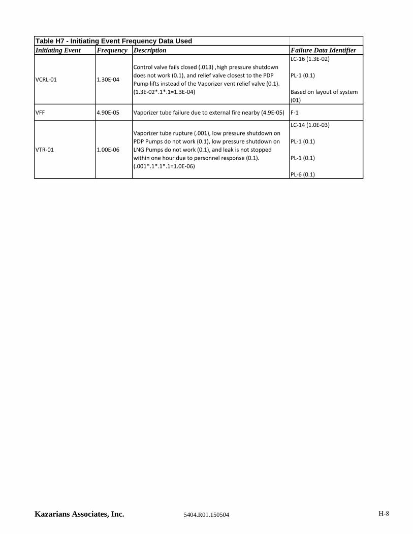
Table H7 - Initiating Event Frequency Data UsedInitiating Event Frequency Description Failure Data Identifier
VCRL‐01 1.30E‐04
Control valve fails closed (.013) ,high pressure shutdown
does not work (0.1), and relief valve closest to the PDP
Pump lifts instead of the Vaporizer vent relief valve (0.1).
(1.3E‐02*.1*.1=1.3E‐04)
LC‐16 (1.3E‐02)
PL‐1 (0.1)
Based on layout of system
(01)
VFF 4.90E‐05 Vaporizer tube failure due to external fire nearby (4.9E‐05) F‐1
VTR‐01 1.00E‐06
Vaporizer tube rupture (.001), low pressure shutdown on
PDP Pumps do not work (0.1), low pressure shutdown on
LNG Pumps do not work (0.1), and leak is not stopped
within one hour due to personnel response (0.1).
(.001*.1*.1*.1=1.0E‐06)
LC‐14 (1.0E‐03)
PL‐1 (0.1)
PL‐1 (0.1)
PL‐6 (0.1)
Kazarians Associates, Inc. 5404.R01.150504 H-8
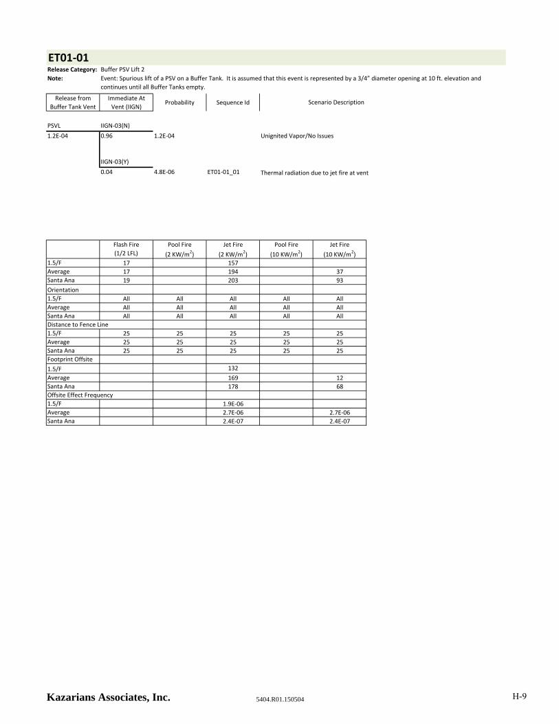
ET01‐01Release Category: Buffer PSV Lift 2
Note:
Release from
Buffer Tank Vent
Immediate At
Vent (IIGN)Probability Sequence Id
PSVL IIGN‐03(N)
1.2E‐04 0.96 1.2E‐04
IIGN‐03(Y)
0.04 4.8E‐06 ET01‐01_01 Thermal radiation due to jet fire at vent
Flash Fire
(1/2 LFL)
Pool Fire
(2 KW/m2)
Jet Fire
(2 KW/m2)
Pool Fire
(10 KW/m2)
Jet Fire
(10 KW/m2)1.5/F 17 157
Average 17 194 37
Santa Ana 19 203 93
Orientation
1.5/F All All All All All
Average All All All All All
Santa Ana All All All All All
Distance to Fence Line
1.5/F 25 25 25 25 25
Average 25 25 25 25 25
Santa Ana 25 25 25 25 25
Footprint Offsite
1.5/F 132
Average 169 12
Santa Ana 178 68
Offsite Effect Frequency
1.5/F 1.9E‐06
Average 2.7E‐06 2.7E‐06
Santa Ana 2.4E‐07 2.4E‐07
Scenario Description
Unignited Vapor/No Issues
Event: Spurious lift of a PSV on a Buffer Tank. It is assumed that this event is represented by a 3/4” diameter opening at 10 ft. elevation and
continues until all Buffer Tanks empty.
Kazarians Associates, Inc. 5404.R01.150504 H-9

ET01‐02Release Category Buffer PSV Lift 1
Note:
Release from
Buffer Tank Vent
Immediate At
Vent (IIGN)Probability Sequence Id
MLSN‐1 IIGN‐03(N)
1.0E‐05 0.96 9.6E‐06
IIGN‐03(Y)
0.04 4.0E‐07 ET01‐02_01 Thermal radiation due to jet fire at vent
Flash Fire
(1/2 LFL)
Pool Fire
(2 KW/m2)
Jet Fire
(2 KW/m2)
Pool Fire
(10 KW/m2)
Jet Fire
(10 KW/m2)1.5/F 19 184
Average 21 226 51
Santa Ana 23 235 108
Orientation
1.5/F All All All All All
Average All All All All All
Santa Ana All All All All All
Distance to Fence Line
1.5/F 25 25 25 25 25
Average 25 25 25 25 25
Santa Ana 25 25 25 25 25
Footprint Offsite
1.5/F 159
Average 201 26
Santa Ana 210 83
Offsite Effect Frequency
1.5/F 1.6E‐07
Average 2.2E‐07 2.2E‐07
Santa Ana 2.0E‐08 2.0E‐08
Event: Failure of the Priority Panel, sending CNG to full Buffer Tanks, resulting in lifting of the Buffer Tank PSVs. It is assumed that this event is
represented by a 1/4” diameter opening at 10 ft. elevation, and continues until the Storage Tank empties.
Scenario Description
Unignited Vapor/No Issues
Kazarians Associates, Inc. 5404.R01.150504 H-10

ET01‐03Release Category: Buffer PSV Lift 1
Note:
Release from
Buffer Tank Vent
Immediate At
Vent (IIGN)Probability Sequence Id
BFL IIGN‐03(N)
4.9E‐05 0.96 4.7E‐05
IIGN‐03(Y)
0.04 2.0E‐06 ET01‐03_01 Thermal radiation due to jet fire at vent
Flash Fire
(1/2 LFL)
Pool Fire
(2 KW/m2)
Jet Fire
(2 KW/m2)
Pool Fire
(10 KW/m2)
Jet Fire
(10 KW/m2)1.5/F 19 184
Average 21 226 51
Santa Ana 23 235 108
Orientation
1.5/F All All All All All
Average All All All All All
Santa Ana All All All All All
Distance to Fence Line
1.5/F 25 25 25 25 25
Average 25 25 25 25 25
Santa Ana 25 25 25 25 25
Footprint Offsite
1.5/F 159
Average 201 26
Santa Ana 210 83
Offsite Effect Frequency
1.5/F 7.6E‐07
Average 1.1E‐06 1.1E‐06
Santa Ana 9.8E‐08 9.8E‐08
Event: External fire near the Buffer Tanks, resulting in lifting of the Buffer Tank PSVs. It is assumed that this event is represented by a 1/4” diameter
opening at 10 ft. elevation, and continues until the Storage Tank empties.
Scenario Description
Unignited Vapor/No Issues
Kazarians Associates, Inc. 5404.R01.150504 H-11

ET01‐04Release Category: HP Liquid Venting 5
Note:
Release from Vent
to Atmosphere
Near Vaporizer
Immediate At
Vent (IIGN)Probability Sequence Id
VCRL‐01 IIGN‐02(N)
1.30E‐04
9.80E‐01 1.3E‐04
IIGN‐02(Y)
0.02 2.6E‐06 ET01‐04_01 Thermal radiation due to jet fire at vent
Flash Fire
(1/2 LFL)
Pool Fire
(2 KW/m2)
Jet Fire
(2 KW/m2)
Pool Fire
(10 KW/m2)
Jet Fire
(10 KW/m2)1.5/F 47
Average 59
Santa Ana 65 29
Orientation
1.5/F All All All All All
Average All All All All All
Santa Ana All All All All All
Distance to Fence Line
1.5/F 38 38 38 38 38
Average 38 38 38 38 38
Santa Ana 38 38 38 38 38
Footprint Offsite
1.5/F 9
Average 21
Santa Ana 27
Offsite Effect Frequency
1.5/F 1.0E‐06
Average 1.5E‐06
Santa Ana 1.3E‐07
Event: Shutoff valve downstream of a Vaporizer closes, causing deadhead of the associated High Pressure Pump. High pressure in the line results in
lifting of the Vaporizer PSV. It is assumed that this event is represented by a 1/4” diameter opening at 10 ft. elevation and continues until the
Storage Tank empties.
Scenario Description
Unignited Vapor/No Issues
Kazarians Associates, Inc. 5404.R01.150504 H-12
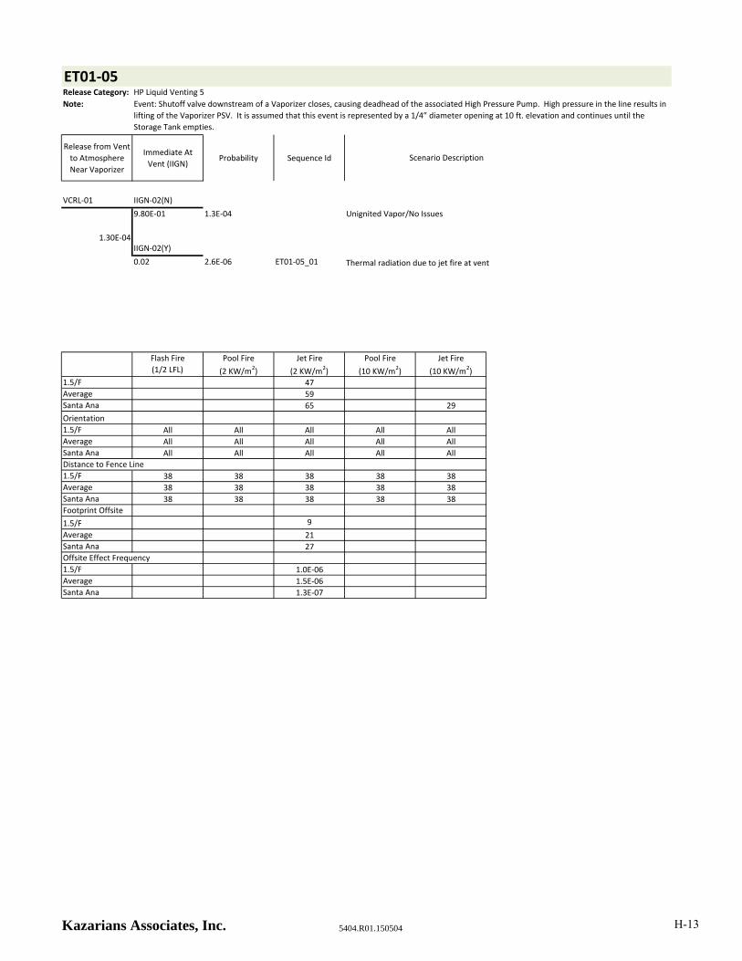
ET01‐05Release Category: HP Liquid Venting 5
Note:
Release from Vent
to Atmosphere
Near Vaporizer
Immediate At
Vent (IIGN)Probability Sequence Id
VCRL‐01 IIGN‐02(N)
1.30E‐04
9.80E‐01 1.3E‐04
IIGN‐02(Y)
0.02 2.6E‐06 ET01‐05_01 Thermal radiation due to jet fire at vent
Flash Fire
(1/2 LFL)
Pool Fire
(2 KW/m2)
Jet Fire
(2 KW/m2)
Pool Fire
(10 KW/m2)
Jet Fire
(10 KW/m2)1.5/F 47
Average 59
Santa Ana 65 29
Orientation
1.5/F All All All All All
Average All All All All All
Santa Ana All All All All All
Distance to Fence Line
1.5/F 38 38 38 38 38
Average 38 38 38 38 38
Santa Ana 38 38 38 38 38
Footprint Offsite
1.5/F 9
Average 21
Santa Ana 27
Offsite Effect Frequency
1.5/F 1.0E‐06
Average 1.5E‐06
Santa Ana 1.3E‐07
Event: Shutoff valve downstream of a Vaporizer closes, causing deadhead of the associated High Pressure Pump. High pressure in the line results in
lifting of the Vaporizer PSV. It is assumed that this event is represented by a 1/4” diameter opening at 10 ft. elevation and continues until the
Storage Tank empties.
Scenario Description
Unignited Vapor/No Issues
Kazarians Associates, Inc. 5404.R01.150504 H-13
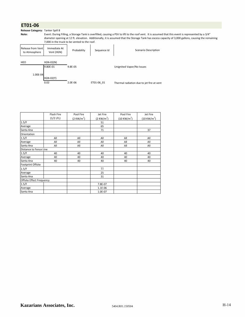
ET01‐06Release Category: Tanker Spill 8
Note:
Release from Vent
to Atmosphere
Immediate At
Vent (IIGN)Probability Sequence Id
HEO IIGN‐02(N)
1.00E‐04
9.80E‐01 9.8E‐05
IIGN‐02(Y)
0.02 2.0E‐06 ET01‐06_01 Thermal radiation due to jet fire at vent
Flash Fire
(1/2 LFL)
Pool Fire
(2 KW/m2)
Jet Fire
(2 KW/m2)
Pool Fire
(10 KW/m2)
Jet Fire
(10 KW/m2)1.5/F 51
Average 65
Santa Ana 71 37
Orientation
1.5/F All All All All All
Average All All All All All
Santa Ana All All All All All
Distance to Fence Line
1.5/F 40 40 40 40 40
Average 40 40 40 40 40
Santa Ana 40 40 40 40 40
Footprint Offsite
1.5/F 11
Average 25
Santa Ana 31
Offsite Effect Frequency
1.5/F 7.8E‐07
Average 1.1E‐06
Santa Ana 1.0E‐07
Event: During Filling, a Storage Tank is overfilled, causing a PSV to lift to the roof vent. It is assumed that this event is represented by a 3/4”
diameter opening at 12 ft. elevation. Additionally, it is assumed that the Storage Tank has excess capacity of 3,000 gallons, causing the remaining
7,000 in the truck to be vented to the roof.
Scenario Description
Unignited Vapor/No Issues
Kazarians Associates, Inc. 5404.R01.150504 H-14

ET01‐07Release Category: LP Liquid Venting 3
Note:
Release from Vent
to Atmosphere
Immediate At
Vent (IIGN)Probability Sequence Id
HEO IIGN‐02(N)
1.00E‐04
9.80E‐01 9.8E‐05
IIGN‐02(Y)
0.02 2.0E‐06 ET01‐07_01 Thermal radiation due to jet fire at vent
Flash Fire
(1/2 LFL)
Pool Fire
(2 KW/m2)
Jet Fire
(2 KW/m2)
Pool Fire
(10 KW/m2)
Jet Fire
(10 KW/m2)1.5/F 47
Average 58
Santa Ana 61 33
Orientation
1.5/F All All All All All
Average All All All All All
Santa Ana All All All All All
Distance to Fence Line
1.5/F 40 40 40 40 40
Average 40 40 40 40 40
Santa Ana 40 40 40 40 40
Footprint Offsite
1.5/F 7
Average 18
Santa Ana 21
Offsite Effect Frequency
1.5/F 7.8E‐07
Average 1.1E‐06
Santa Ana 1.0E‐07
Event: Venting liquid to the roof vent through AOV‐27 during normal filling operation. It is assumed that this event is represented by a 1/2”
diameter opening at 12 ft. elevation and continues for 30 seconds.
Scenario Description
Unignited Vapor/No Issues
Kazarians Associates, Inc. 5404.R01.150504 H-15

ET01‐08Release Category: LP Vapor Venting 1
Note:
Release from Vent
to Atmosphere
Immediate At
Vent (IIGN)Probability Sequence Id
PSVL IIGN‐02(N)
2.00E‐05
9.80E‐01 2.0E‐05
IIGN‐02(Y)
0.02 4.0E‐07 ET01‐08_01 Thermal radiation due to jet fire at vent
Flash Fire
(1/2 LFL)
Pool Fire
(2 KW/m2)
Jet Fire
(2 KW/m2)
Pool Fire
(10 KW/m2)
Jet Fire
(10 KW/m2)1.5/F 35
Average 49
Santa Ana 55 33
Orientation
1.5/F All All All All All
Average All All All All All
Santa Ana All All All All All
Distance to Fence Line
1.5/F 40 40 40 40 40
Average 40 40 40 40 40
Santa Ana 40 40 40 40 40
Footprint Offsite
1.5/F
Average 9
Santa Ana 15
Offsite Effect Frequency
1.5/F
Average 2.2E‐07
Santa Ana 2.0E‐08
Event: Spurious lift of a PSV on a 1/3 full Storage Tank. It is assumed that this event is represented by a 3/4” diameter opening at 12 ft. elevation
and continues until the Storage Tank empties.
Scenario Description
Unignited Vapor/No Issues
Kazarians Associates, Inc. 5404.R01.150504 H-16

ET01‐09Release Category: LP Vapor Venting 2
Note:
Release from Vent
to Atmosphere
Immediate At
Vent (IIGN)Probability Sequence Id
PSVL IIGN‐02(N)
2.00E‐05
9.80E‐01 2.0E‐05
IIGN‐02(Y)
0.02 4.0E‐07 ET01‐09_01 Thermal radiation due to jet fire at vent
Flash Fire
(1/2 LFL)
Pool Fire
(2 KW/m2)
Jet Fire
(2 KW/m2)
Pool Fire
(10 KW/m2)
Jet Fire
(10 KW/m2)1.5/F
Average 33
Santa Ana 43 16
Orientation
1.5/F All All All All All
Average All All All All All
Santa Ana All All All All All
Distance to Fence Line
1.5/F 40 40 40 40 40
Average 40 40 40 40 40
Santa Ana 40 40 40 40 40
Footprint Offsite
1.5/F
Average
Santa Ana 3
Offsite Effect Frequency
1.5/F
Average
Santa Ana 2.0E‐08
Event: Spurious lift of a PSV on a full Storage Tank. It is assumed that this event is represented by a 3/4” diameter opening at 12 ft. elevation and
continues until the Storage Tank empties.
Scenario Description
Unignited Vapor/No Issues
Kazarians Associates, Inc. 5404.R01.150504 H-17

ET01‐10Release Category LP Vapor Venting 1
Note:
Release from Vent
to Atmosphere
Immediate At
Vent (IIGN)Probability Sequence Id
STFL IIGN‐02(N)
4.90E‐05
9.80E‐01 4.8E‐05
IIGN‐02(Y)
0.02 9.8E‐07 ET01‐10_01 Thermal radiation due to jet fire at vent
Flash Fire
(1/2 LFL)
Pool Fire
(2 KW/m2)
Jet Fire
(2 KW/m2)
Pool Fire
(10 KW/m2)
Jet Fire
(10 KW/m2)1.5/F 35
Average 49
Santa Ana 55 33
Orientation
1.5/F All All All All All
Average All All All All All
Santa Ana All All All All All
Distance to Fence Line
1.5/F 40 40 40 40 40
Average 40 40 40 40 40
Santa Ana 40 40 40 40 40
Footprint Offsite
1.5/F
Average 9
Santa Ana 15
Offsite Effect Frequency
1.5/F
Average 5.5E‐07
Santa Ana 4.9E‐08
Event: Lift of a PSV on a 1/3 full Storage Tank due to external fire. It is assumed that this event is represented by a 3/4” diameter opening at 12 ft.
elevation and continues until the Storage Tank empties.
Scenario Description
Unignited Vapor/No Issues
Kazarians Associates, Inc. 5404.R01.150504 H-18

ET01‐11Release Category LP Vapor Venting 2
Note:
Release from Vent
to Atmosphere
Immediate At
Vent (IIGN)Probability Sequence Id
STFL IIGN‐02(N)
4.90E‐05
9.80E‐01 4.8E‐05
IIGN‐02(Y)
0.02 9.8E‐07 ET01‐11_01 Thermal radiation due to jet fire at vent
Flash Fire
(1/2 LFL)
Pool Fire
(2 KW/m2)
Jet Fire
(2 KW/m2)
Pool Fire
(10 KW/m2)
Jet Fire
(10 KW/m2)1.5/F
Average 33
Santa Ana 43 16
Orientation
1.5/F All All All All All
Average All All All All All
Santa Ana All All All All All
Distance to Fence Line
1.5/F 40 40 40 40 40
Average 40 40 40 40 40
Santa Ana 40 40 40 40 40
Footprint Offsite
1.5/F
Average
Santa Ana 3
Offsite Effect Frequency
1.5/F
Average
Santa Ana 4.9E‐08
Event: Lift of a PSV on a full Storage Tank due to external fire. It is assumed that this event is represented by a 3/4” diameter opening at 12 ft.
elevation and continues until the Storage Tank empties.
Scenario Description
Unignited Vapor/No Issues
Kazarians Associates, Inc. 5404.R01.150504 H-19
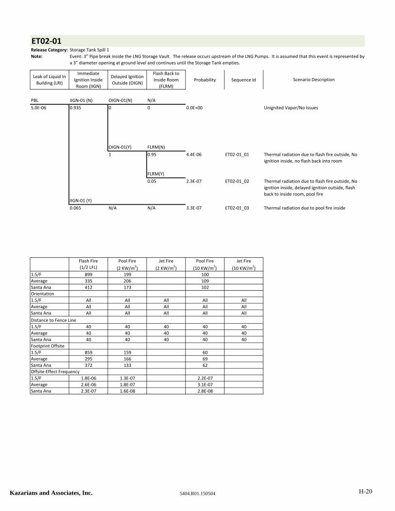
ET02‐01Release Category: Storage Tank Spill 1
Note:
Leak of Liquid In
Building (LRI)
Immediate
Ignition Inside
Room (IIGN)
Delayed Ignition
Outside (OIGN)
Flash Back to
Inside Room
(FLRM)
Probability Sequence Id
PBL IIGN‐01 (N) OIGN‐01(N) N/A
5.0E‐06 0.935 0 0 0.0E+00 Unignited Vapor/No Issues
OIGN‐01(Y) FLRM(N)
1 0.95 4.4E‐06 ET02‐01_01
FLRM(Y)
0.05 2.3E‐07 ET02‐01_02
IIGN‐01 (Y)
0.065 N/A N/A 3.3E‐07 ET02‐01_03
Flash Fire
(1/2 LFL)
Pool Fire
(2 KW/m2)
Jet Fire
(2 KW/m2)
Pool Fire
(10 KW/m2)
Jet Fire
(10 KW/m2)
1.5/F 899 199 100
Average 335 206 109
Santa Ana 412 173 102
Orientation
1.5/F All All All All All
Average All All All All All
Santa Ana All All All All All
Distance to Fence Line
1.5/F 40 40 40 40 40
Average 40 40 40 40 40
Santa Ana 40 40 40 40 40
Footprint Offsite
1.5/F 859 159 60
Average 295 166 69
Santa Ana 372 133 62
Offsite Effect Frequency
1.5/F 1.8E‐06 1.3E‐07 2.2E‐07
Average 2.6E‐06 1.8E‐07 3.1E‐07
Santa Ana 2.3E‐07 1.6E‐08 2.8E‐08
Thermal radiation due to flash fire outside, No
ignition inside, no flash back into room
Thermal radiation due to flash fire outside, No
ignition inside, delayed ignition outside, flash
back to inside room, pool fire
Thermal radiation due to pool fire inside
Scenario Description
Event: 3” Pipe break inside the LNG Storage Vault. The release occurs upstream of the LNG Pumps. It is assumed that this event is represented by
a 3” diameter opening at ground level and continues until the Storage Tank empties.
Kazarians and Associates, Inc. 5404.R01.150504 H-20
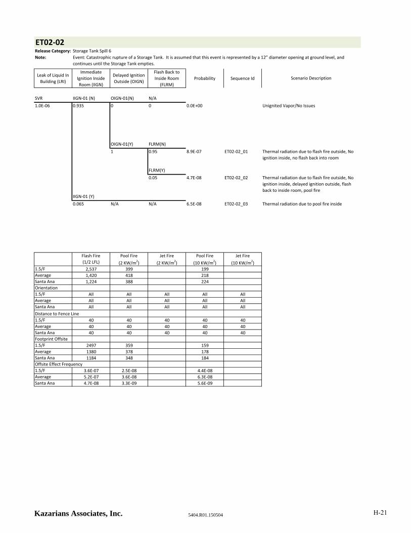
ET02‐02Release Category: Storage Tank Spill 6
Note:
Leak of Liquid In
Building (LRI)
Immediate
Ignition Inside
Room (IIGN)
Delayed Ignition
Outside (OIGN)
Flash Back to
Inside Room
(FLRM)
Probability Sequence Id
SVR IIGN‐01 (N) OIGN‐01(N) N/A
1.0E‐06 0.935 0 0 0.0E+00 Unignited Vapor/No Issues
OIGN‐01(Y) FLRM(N)
1 0.95 8.9E‐07 ET02‐02_01
FLRM(Y)
0.05 4.7E‐08 ET02‐02_02
IIGN‐01 (Y)
0.065 N/A N/A 6.5E‐08 ET02‐02_03
Flash Fire
(1/2 LFL)
Pool Fire
(2 KW/m2)
Jet Fire
(2 KW/m2)
Pool Fire
(10 KW/m2)
Jet Fire
(10 KW/m2)1.5/F 2,537 399 199
Average 1,420 418 218
Santa Ana 1,224 388 224
Orientation
1.5/F All All All All All
Average All All All All All
Santa Ana All All All All All
Distance to Fence Line
1.5/F 40 40 40 40 40
Average 40 40 40 40 40
Santa Ana 40 40 40 40 40
Footprint Offsite
1.5/F 2497 359 159
Average 1380 378 178
Santa Ana 1184 348 184
Offsite Effect Frequency
1.5/F 3.6E‐07 2.5E‐08 4.4E‐08
Average 5.2E‐07 3.6E‐08 6.3E‐08
Santa Ana 4.7E‐08 3.3E‐09 5.6E‐09
Scenario Description
Thermal radiation due to flash fire outside, No
ignition inside, no flash back into room
Thermal radiation due to flash fire outside, No
ignition inside, delayed ignition outside, flash
back to inside room, pool fire
Thermal radiation due to pool fire inside
Event: Catastrophic rupture of a Storage Tank. It is assumed that this event is represented by a 12” diameter opening at ground level, and
continues until the Storage Tank empties.
Kazarians Associates, Inc. 5404.R01.150504 H-21
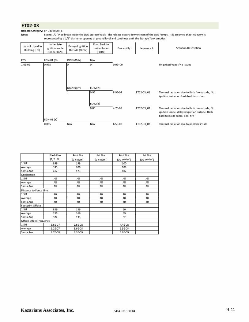
ET02‐03Release Category: LP Liquid Spill 6
Note:
Leak of Liquid In
Building (LRI)
Immediate
Ignition Inside
Room (IIGN)
Delayed Ignition
Outside (OIGN)
Flash Back to
Inside Room
(FLRM)
Probability Sequence Id
PBS IIGN‐01 (N) OIGN‐01(N) N/A
1.0E‐06 0.935 0 0 0.0E+00 Unignited Vapor/No Issues
OIGN‐01(Y) FLRM(N)
1 0.95 8.9E‐07 ET02‐03_01
FLRM(Y)
0.05 4.7E‐08 ET02‐03_02
IIGN‐01 (Y)
0.065 N/A N/A 6.5E‐08 ET02‐03_03
Flash Fire
(1/2 LFL)
Pool Fire
(2 KW/m2)
Jet Fire
(2 KW/m2)
Pool Fire
(10 KW/m2)
Jet Fire
(10 KW/m2)1.5/F 899 199 100
Average 335 206 109
Santa Ana 412 173 102
Orientation
1.5/F All All All All All
Average All All All All All
Santa Ana All All All All All
Distance to Fence Line
1.5/F 40 40 40 40 40
Average 40 40 40 40 40
Santa Ana 40 40 40 40 40
Footprint Offsite
1.5/F 859 159 60
Average 295 166 69
Santa Ana 372 133 62
Offsite Effect Frequency
1.5/F 3.6E‐07 2.5E‐08 4.4E‐08
Average 5.2E‐07 3.6E‐08 6.3E‐08
Santa Ana 4.7E‐08 3.3E‐09 5.6E‐09
Scenario Description
Thermal radiation due to flash fire outside, No
ignition inside, no flash back into room
Thermal radiation due to flash fire outside, No
ignition inside, delayed ignition outside, flash
back to inside room, pool fire
Thermal radiation due to pool fire inside
Event: 1/2” Pipe break inside the LNG Storage Vault. The release occurs downstream of the LNG Pumps. It is assumed that this event is
represented by a 1/2” diameter opening at ground level and continues until the Storage Tank empties.
Kazarians Associates, Inc. 5404.R01.150504 H-22

ET02‐04Release Category: HP Liquid Spill 3
Note:
Leak of Liquid In
Building (LRI)
Immediate
Ignition Inside
Room (IIGN)
Delayed Ignition
Outside (OIGN)
Flash Back to
Inside Room
(FLRM)
Probability Sequence Id
HERFDL‐01 IIGN‐01 (N) OIGN‐01(N) N/A
1.0E‐05 0.935 0 0 0.0E+00 Unignited Vapor/No Issues
OIGN‐01(Y) FLRM(N)
1 0.95 8.9E‐06 ET02‐04_01
FLRM(Y)
0.05 4.7E‐07 ET02‐04_02
IIGN‐01 (Y)
0.065 N/A N/A 6.5E‐07 ET02‐04_03
Flash Fire
(1/2 LFL)
Pool Fire
(2 KW/m2)
Jet Fire
(2 KW/m2)
Pool Fire
(10 KW/m2)
Jet Fire
(10 KW/m2)1.5/F 929 199 100
Average 486 206 109
Santa Ana 456 192 113
Orientation
1.5/F All All All All All
Average All All All All All
Santa Ana All All All All All
Distance to Fence Line
1.5/F 40 40 40 40 40
Average 40 40 40 40 40
Santa Ana 40 40 40 40 40
Footprint Offsite
1.5/F 889 159 60
Average 446 166 69
Santa Ana 416 152 73
Offsite Effect Frequency
1.5/F 3.6E‐06 2.5E‐07 4.4E‐07
Average 5.2E‐06 3.6E‐07 6.3E‐07
Santa Ana 4.7E‐07 3.3E‐08 5.6E‐08
Event: 1” Pipe break inside the LNG Storage Vault. The release occurs downstream of the High Pressure Pumps. It is assumed that this event is
represented by a 1” diameter opening at ground level and continues until the Storage Tank empties.
Scenario Description
Thermal radiation due to flash fire outside, No
ignition inside, no flash back into room
Thermal radiation due to flash fire outside, No
ignition inside, delayed ignition outside, flash
back to inside room, pool fire
Thermal radiation due to pool fire inside
Kazarians Associates, Inc. 5404.R01.150504 H-23
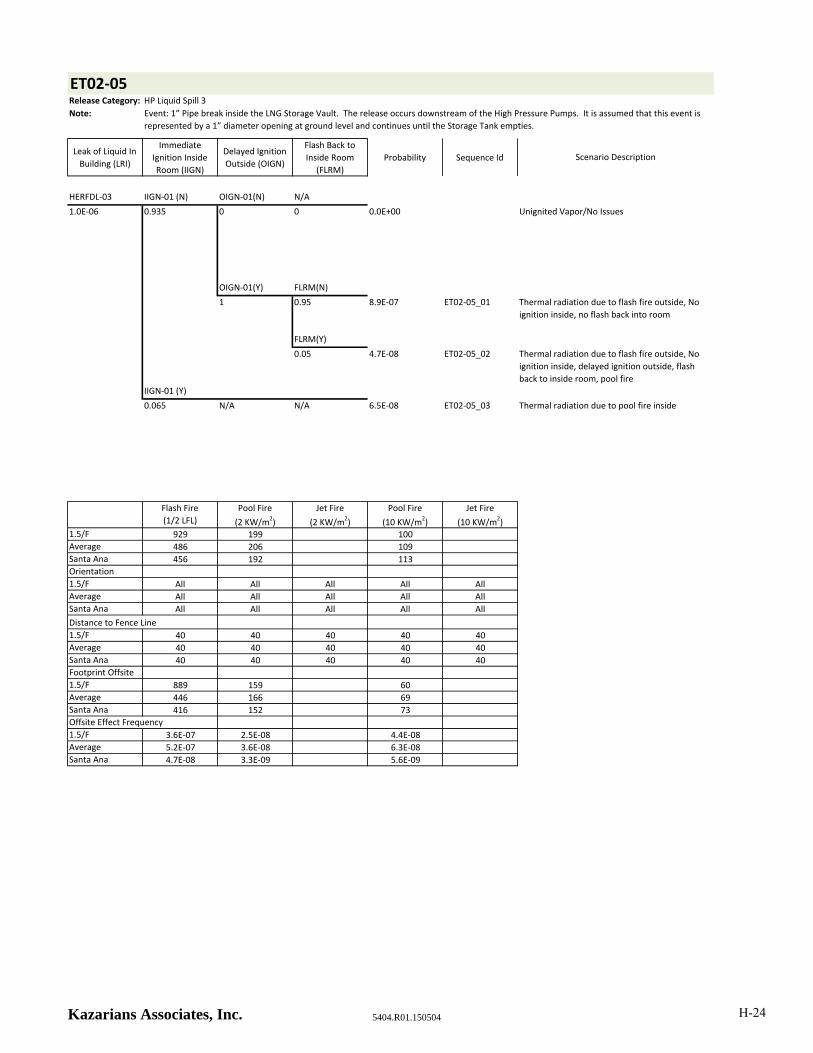
ET02‐05Release Category: HP Liquid Spill 3
Note:
Leak of Liquid In
Building (LRI)
Immediate
Ignition Inside
Room (IIGN)
Delayed Ignition
Outside (OIGN)
Flash Back to
Inside Room
(FLRM)
Probability Sequence Id
HERFDL‐03 IIGN‐01 (N) OIGN‐01(N) N/A
1.0E‐06 0.935 0 0 0.0E+00 Unignited Vapor/No Issues
OIGN‐01(Y) FLRM(N)
1 0.95 8.9E‐07 ET02‐05_01
FLRM(Y)
0.05 4.7E‐08 ET02‐05_02
IIGN‐01 (Y)
0.065 N/A N/A 6.5E‐08 ET02‐05_03
Flash Fire
(1/2 LFL)
Pool Fire
(2 KW/m2)
Jet Fire
(2 KW/m2)
Pool Fire
(10 KW/m2)
Jet Fire
(10 KW/m2)1.5/F 929 199 100
Average 486 206 109
Santa Ana 456 192 113
Orientation
1.5/F All All All All All
Average All All All All All
Santa Ana All All All All All
Distance to Fence Line
1.5/F 40 40 40 40 40
Average 40 40 40 40 40
Santa Ana 40 40 40 40 40
Footprint Offsite
1.5/F 889 159 60
Average 446 166 69
Santa Ana 416 152 73
Offsite Effect Frequency
1.5/F 3.6E‐07 2.5E‐08 4.4E‐08
Average 5.2E‐07 3.6E‐08 6.3E‐08
Santa Ana 4.7E‐08 3.3E‐09 5.6E‐09
Event: 1” Pipe break inside the LNG Storage Vault. The release occurs downstream of the High Pressure Pumps. It is assumed that this event is
represented by a 1” diameter opening at ground level and continues until the Storage Tank empties.
Scenario Description
Thermal radiation due to flash fire outside, No
ignition inside, no flash back into room
Thermal radiation due to flash fire outside, No
ignition inside, delayed ignition outside, flash
back to inside room, pool fire
Thermal radiation due to pool fire inside
Kazarians Associates, Inc. 5404.R01.150504 H-24

ET02‐06Release Category: HP Liquid Spill 3
Note:
Leak of Liquid In
Building (LRI)
Immediate
Ignition Inside
Room (IIGN)
Delayed Ignition
Outside (OIGN)
Flash Back to
Inside Room
(FLRM)
Probability Sequence Id
HERFDL‐02 IIGN‐01 (N) OIGN‐01(N) N/A
1.3E‐06 0.935 0 0 0.0E+00 Unignited Vapor/No Issues
OIGN‐01(Y) FLRM(N)
1 0.95 1.2E‐06 ET02‐06_01
FLRM(Y)
0.05 6.1E‐08 ET02‐06_02
IIGN‐01 (Y)
0.065 N/A N/A 8.4E‐08 ET02‐06_03
Flash Fire
(1/2 LFL)
Pool Fire
(2 KW/m2)
Jet Fire
(2 KW/m2)
Pool Fire
(10 KW/m2)
Jet Fire
(10 KW/m2)1.5/F 929 199 100
Average 486 206 109
Santa Ana 456 192 113
Orientation
1.5/F All All All All All
Average All All All All All
Santa Ana All All All All All
Distance to Fence Line
1.5/F 40 40 40 40 40
Average 40 40 40 40 40
Santa Ana 40 40 40 40 40
Footprint Offsite
1.5/F 889 159 60
Average 446 166 69
Santa Ana 416 152 73
Offsite Effect Frequency
1.5/F 4.7E‐07 3.3E‐08 5.7E‐08
Average 6.8E‐07 4.7E‐08 8.1E‐08
Santa Ana 6.1E‐08 4.2E‐09 7.3E‐09
Event: 1” Pipe break inside the LNG Storage Vault. The release occurs downstream of the High Pressure Pumps. It is assumed that this event is
represented by a 1” diameter opening at ground level and continues until the Storage Tank empties.
Scenario Description
Thermal radiation due to flash fire outside, No
ignition inside, no flash back into room
Thermal radiation due to flash fire outside, No
ignition inside, delayed ignition outside, flash
back to inside room, pool fire
Thermal radiation due to pool fire inside
Kazarians Associates, Inc. 5404.R01.150504 H-25

ET02‐07Release Category: HP Liquid Spill 2
Note:
Leak of Liquid In
Building (LRI)
Immediate
Ignition Inside
Room (IIGN)
Delayed Ignition
Outside (OIGN)
Flash Back to
Inside Room
(FLRM)
Probability Sequence Id
PBS IIGN‐01 (N) OIGN‐01(N) N/A
1.2E‐06 0.935 0 0 0.0E+00 Unignited Vapor/No Issues
OIGN‐01(Y) FLRM(N)
1 0.95 1.1E‐06 ET02‐07_01
FLRM(Y)
0.05 5.6E‐08 ET02‐07_02
IIGN‐01 (Y)
0.065 N/A N/A 7.8E‐08 ET02‐07_03
Flash Fire
(1/2 LFL)
Pool Fire
(2 KW/m2)
Jet Fire
(2 KW/m2)
Pool Fire
(10 KW/m2)
Jet Fire
(10 KW/m2)
1.5/F 698 199 100
Average 353 206 109
Santa Ana 342 165 98
Orientation
1.5/F All All All All All
Average All All All All All
Santa Ana All All All All All
Distance to Fence Line
1.5/F 40 40 40 40 40
Average 40 40 40 40 40
Santa Ana 40 40 40 40 40
Footprint Offsite
1.5/F 658 159 60
Average 313 166 69
Santa Ana 302 125 58
Offsite Effect Frequency
1.5/F 4.4E‐07 3.0E‐08 5.2E‐08
Average 6.3E‐07 4.4E‐08 7.5E‐08
Santa Ana 5.6E‐08 3.9E‐09 6.7E‐09
Event: 3/4” Pipe break inside the LNG Storage Vault. The release occurs downstream of the High Pressure Pumps. It is assumed that this event is
represented by a 3/4” diameter opening at ground level and continues for 1 hour.
Scenario Description
Thermal radiation due to flash fire outside, No
ignition inside, no flash back into room
Thermal radiation due to flash fire outside, No
ignition inside, delayed ignition outside, flash
back to inside room, pool fire
Thermal radiation due to pool fire inside
Kazarians and Associates, Inc. 5404.R01.150504 H-26

ET02‐08Release Category: HP Liquid Spill 3
Note:
Leak of Liquid In
Building (LRI)
Immediate
Ignition Inside
Room (IIGN)
Delayed Ignition
Outside (OIGN)
Flash Back to
Inside Room
(FLRM)
Probability Sequence Id
PBS IIGN‐01 (N) OIGN‐01(N) N/A
1.0E‐06 0.935 0 0 0.0E+00 Unignited Vapor/No Issues
OIGN‐01(Y) FLRM(N)
1 0.95 8.9E‐07 ET02‐08_01
FLRM(Y)
0.05 4.7E‐08 ET02‐08_02
IIGN‐01 (Y)
0.065 N/A N/A 6.5E‐08 ET02‐08_03
Flash Fire
(1/2 LFL)
Pool Fire
(2 KW/m2)
Jet Fire
(2 KW/m2)
Pool Fire
(10 KW/m2)
Jet Fire
(10 KW/m2)
1.5/F 929 199 100
Average 486 206 109
Santa Ana 456 192 113
Orientation
1.5/F All All All All All
Average All All All All All
Santa Ana All All All All All
Distance to Fence Line
1.5/F 40 40 40 40 40
Average 40 40 40 40 40
Santa Ana 40 40 40 40 40
Footprint Offsite
1.5/F 889 159 60
Average 446 166 69
Santa Ana 416 152 73
Offsite Effect Frequency
1.5/F 3.6E‐07 2.5E‐08 4.4E‐08
Average 5.2E‐07 3.6E‐08 6.3E‐08
Santa Ana 4.7E‐08 3.3E‐09 5.6E‐09
Event: 1” Pipe break inside the LNG Storage Vault. The release occurs downstream of the High Pressure Pumps. It is assumed that this event is
represented by a 1” diameter opening at ground level and continues until the Storage Tank empties.
Scenario Description
Thermal radiation due to flash fire outside, No
ignition inside, no flash back into room
Thermal radiation due to flash fire outside, No
ignition inside, delayed ignition outside, flash
back to inside room, pool fire
Thermal radiation due to pool fire inside
Kazarians and Associates, Inc. 5404.R01.150504 H-27
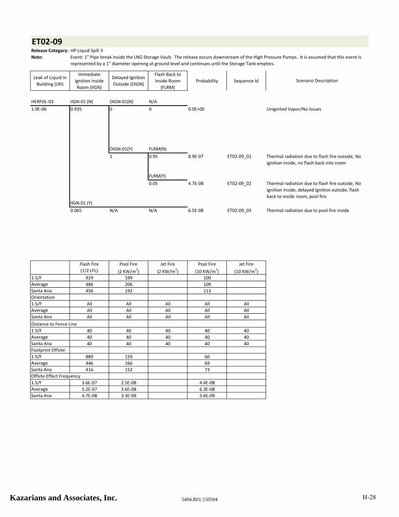
ET02‐09Release Category: HP Liquid Spill 3
Note:
Leak of Liquid In
Building (LRI)
Immediate
Ignition Inside
Room (IIGN)
Delayed Ignition
Outside (OIGN)
Flash Back to
Inside Room
(FLRM)
Probability Sequence Id
HERFDL‐03 IIGN‐01 (N) OIGN‐01(N) N/A
1.0E‐06 0.935 0 0 0.0E+00 Unignited Vapor/No Issues
OIGN‐01(Y) FLRM(N)
1 0.95 8.9E‐07 ET02‐09_01
FLRM(Y)
0.05 4.7E‐08 ET02‐09_02
IIGN‐01 (Y)
0.065 N/A N/A 6.5E‐08 ET02‐09_03
Flash Fire
(1/2 LFL)
Pool Fire
(2 KW/m2)
Jet Fire
(2 KW/m2)
Pool Fire
(10 KW/m2)
Jet Fire
(10 KW/m2)
1.5/F 929 199 100
Average 486 206 109
Santa Ana 456 192 113
Orientation
1.5/F All All All All All
Average All All All All All
Santa Ana All All All All All
Distance to Fence Line
1.5/F 40 40 40 40 40
Average 40 40 40 40 40
Santa Ana 40 40 40 40 40
Footprint Offsite
1.5/F 889 159 60
Average 446 166 69
Santa Ana 416 152 73
Offsite Effect Frequency
1.5/F 3.6E‐07 2.5E‐08 4.4E‐08
Average 5.2E‐07 3.6E‐08 6.3E‐08
Santa Ana 4.7E‐08 3.3E‐09 5.6E‐09
Event: 1” Pipe break inside the LNG Storage Vault. The release occurs downstream of the High Pressure Pumps. It is assumed that this event is
represented by a 1” diameter opening at ground level and continues until the Storage Tank empties.
Scenario Description
Thermal radiation due to flash fire outside, No
ignition inside, no flash back into room
Thermal radiation due to flash fire outside, No
ignition inside, delayed ignition outside, flash
back to inside room, pool fire
Thermal radiation due to pool fire inside
Kazarians and Associates, Inc. 5404.R01.150504 H-28

ET02‐10Release Category: HP Liquid Spill 3
Note:
Leak of Liquid In
Building (LRI)
Immediate
Ignition Inside
Room (IIGN)
Delayed Ignition
Outside (OIGN)
Flash Back to
Inside Room
(FLRM)
Probability Sequence Id
HERFDL‐02 IIGN‐01 (N) OIGN‐01(N) N/A
1.3E‐06 0.935 0 0 0.0E+00 Unignited Vapor/No Issues
OIGN‐01(Y) FLRM(N)
1 0.95 1.2E‐06 ET02‐10_01
FLRM(Y)
0.05 6.1E‐08 ET02‐10_02
IIGN‐01 (Y)
0.065 N/A N/A 8.4E‐08 ET02‐10_03
Flash Fire
(1/2 LFL)
Pool Fire
(2 KW/m2)
Jet Fire
(2 KW/m2)
Pool Fire
(10 KW/m2)
Jet Fire
(10 KW/m2)
1.5/F 929 199 100
Average 486 206 109
Santa Ana 456 192 113
Orientation
1.5/F All All All All All
Average All All All All All
Santa Ana All All All All All
Distance to Fence Line
1.5/F 40 40 40 40 40
Average 40 40 40 40 40
Santa Ana 40 40 40 40 40
Footprint Offsite
1.5/F 889 159 60
Average 446 166 69
Santa Ana 416 152 73
Offsite Effect Frequency
1.5/F 4.7E‐07 3.3E‐08 5.7E‐08
Average 6.8E‐07 4.7E‐08 8.1E‐08
Santa Ana 6.1E‐08 4.2E‐09 7.3E‐09
Event: 1” Pipe break inside the LNG Storage Vault. The release occurs downstream of the High Pressure Pumps. It is assumed that this event is
represented by a 1” diameter opening at ground level and continues until the Storage Tank empties.
Scenario Description
Thermal radiation due to flash fire outside, No
ignition inside, no flash back into room
Thermal radiation due to flash fire outside, No
ignition inside, delayed ignition outside, flash
back to inside room, pool fire
Thermal radiation due to pool fire inside
Kazarians and Associates, Inc. 5404.R01.150504 H-29
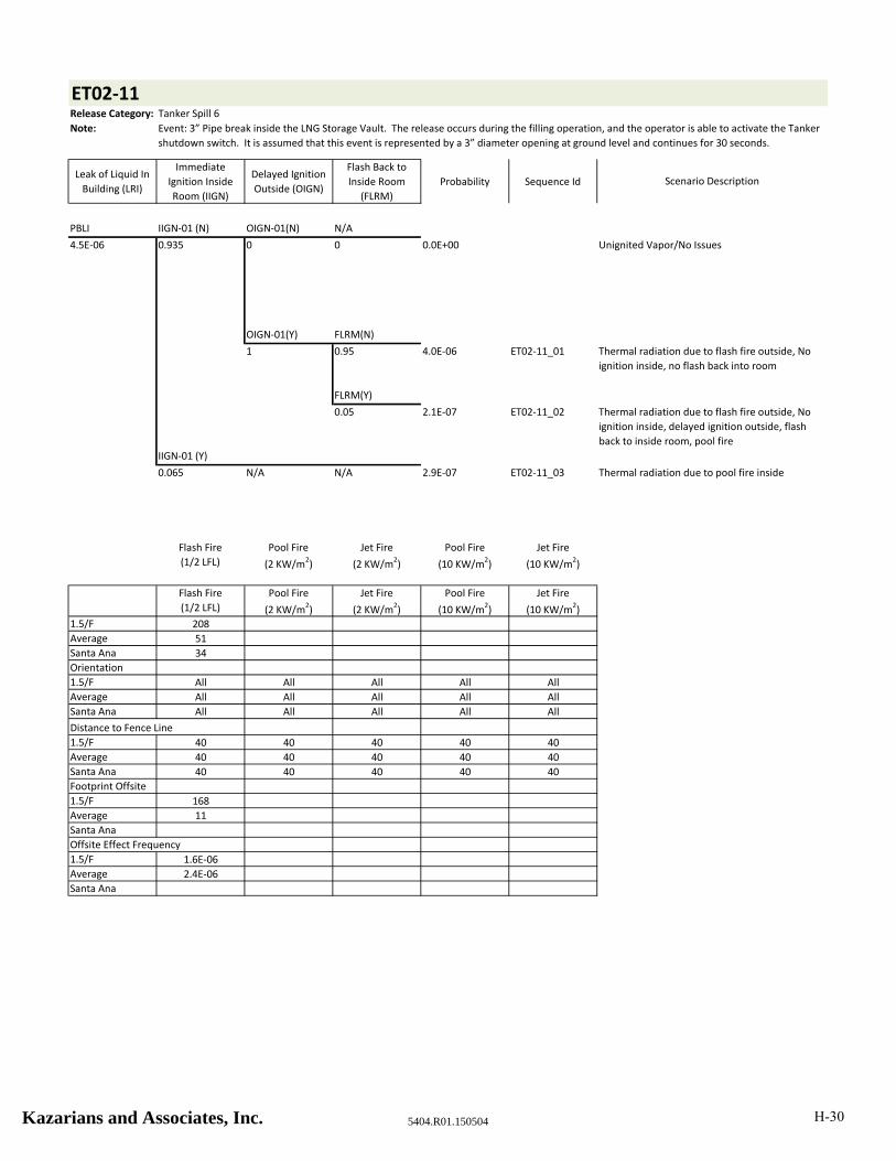
ET02‐11Release Category: Tanker Spill 6
Note:
Leak of Liquid In
Building (LRI)
Immediate
Ignition Inside
Room (IIGN)
Delayed Ignition
Outside (OIGN)
Flash Back to
Inside Room
(FLRM)
Probability Sequence Id
PBLI IIGN‐01 (N) OIGN‐01(N) N/A
4.5E‐06 0.935 0 0 0.0E+00 Unignited Vapor/No Issues
OIGN‐01(Y) FLRM(N)
1 0.95 4.0E‐06 ET02‐11_01
FLRM(Y)
0.05 2.1E‐07 ET02‐11_02
IIGN‐01 (Y)
0.065 N/A N/A 2.9E‐07 ET02‐11_03
Flash Fire
(1/2 LFL)
Pool Fire
(2 KW/m2)
Jet Fire
(2 KW/m2)
Pool Fire
(10 KW/m2)
Jet Fire
(10 KW/m2)
Flash Fire
(1/2 LFL)
Pool Fire
(2 KW/m2)
Jet Fire
(2 KW/m2)
Pool Fire
(10 KW/m2)
Jet Fire
(10 KW/m2)
1.5/F 208
Average 51
Santa Ana 34
Orientation
1.5/F All All All All All
Average All All All All All
Santa Ana All All All All All
Distance to Fence Line
1.5/F 40 40 40 40 40
Average 40 40 40 40 40
Santa Ana 40 40 40 40 40
Footprint Offsite
1.5/F 168
Average 11
Santa Ana
Offsite Effect Frequency
1.5/F 1.6E‐06
Average 2.4E‐06
Santa Ana
Event: 3” Pipe break inside the LNG Storage Vault. The release occurs during the filling operation, and the operator is able to activate the Tanker
shutdown switch. It is assumed that this event is represented by a 3” diameter opening at ground level and continues for 30 seconds.
Scenario Description
Thermal radiation due to flash fire outside, No
ignition inside, no flash back into room
Thermal radiation due to flash fire outside, No
ignition inside, delayed ignition outside, flash
back to inside room, pool fire
Thermal radiation due to pool fire inside
Kazarians and Associates, Inc. 5404.R01.150504 H-30
ET02‐12Release Category: Tanker Spill 7
Note:
Leak of Liquid In
Building (LRI)
Immediate
Ignition Inside
Room (IIGN)
Delayed Ignition
Outside (OIGN)
Flash Back to
Inside Room
(FLRM)
Probability Sequence Id
PBL IIGN‐01 (N) OIGN‐01(N) N/A
5.0E‐06 0.935 0 0 0.0E+00 Unignited Vapor/No Issues
OIGN‐01(Y) FLRM(N)
1 0.95 4.4E‐06 ET02‐12_01
FLRM(Y)
0.05 2.3E‐07 ET02‐12_02
IIGN‐01 (Y)
0.065 N/A N/A 3.3E‐07 ET02‐12_03
Flash Fire
(1/2 LFL)
Pool Fire
(2 KW/m2)
Jet Fire
(2 KW/m2)
Pool Fire
(10 KW/m2)
Jet Fire
(10 KW/m2)
1.5/F 1,015 199 100
Average 383 206 108
Santa Ana 443 191 113
Orientation
1.5/F All All All All All
Average All All All All All
Santa Ana All All All All All
Distance to Fence Line
1.5/F 40 40 40 40 40
Average 40 40 40 40 40
Santa Ana 40 40 40 40 40
Footprint Offsite
1.5/F 975 159 60
Average 343 166 68
Santa Ana 403 151 73
Offsite Effect Frequency
1.5/F 1.8E‐06 1.3E‐07 2.2E‐07
Average 2.6E‐06 1.8E‐07 3.1E‐07
Santa Ana 2.3E‐07 1.6E‐08 2.8E‐08
Event: 3” Pipe break inside the LNG Storage Vault. The release occurs during the filling operation, and the driver is unable to activate the
shutdown switch. It is assumed that this event is represented by a 3” diameter opening at ground level and continues until the Tanker empties.
Scenario Description
Thermal radiation due to flash fire outside, No
ignition inside, no flash back into room
Thermal radiation due to flash fire outside, No
ignition inside, delayed ignition outside, flash
back to inside room, pool fire
Thermal radiation due to pool fire inside
Kazarians and Associates, Inc. 5404.R01.150504 H-31
ET02‐13Release Category: LP Liquid Spill 3
Note:
Leak of Liquid In
Building (LRI)
Immediate
Ignition Inside
Room (IIGN)
Delayed Ignition
Outside (OIGN)
Flash Back to
Inside Room
(FLRM)
Probability Sequence Id
PBS IIGN‐01 (N) OIGN‐01(N) N/A
1.0E‐05 0.935 0 0 0.0E+00 Unignited Vapor/No Issues
OIGN‐01(Y) FLRM(N)
1 0.95 8.9E‐06 ET02‐13_01
FLRM(Y)
0.05 4.7E‐07 ET02‐13_02
IIGN‐01 (Y)
0.065 N/A N/A 6.5E‐07 ET02‐13_03
Flash Fire
(1/2 LFL)
Pool Fire
(2 KW/m2)
Jet Fire
(2 KW/m2)
Pool Fire
(10 KW/m2)
Jet Fire
(10 KW/m2)
1.5/F 300 1.6
Average 80 21 12
Santa Ana 54 9 6
Orientation
1.5/F All All All All All
Average All All All All All
Santa Ana All All All All All
Distance to Fence Line
1.5/F 40 40 40 40 40
Average 40 40 40 40 40
Santa Ana 40 40 40 40 40
Footprint Offsite
1.5/F 260
Average 40
Santa Ana 14
Offsite Effect Frequency
1.5/F 3.6E‐06
Average 5.2E‐06
Santa Ana 4.7E‐07
Event: 1” Pipe break inside the LNG Storage Vault. The release occurs during the filling operation. It is assumed that this event is represented by
a 1” diameter opening at ground level and continues until the Tanker empties.
Scenario Description
Thermal radiation due to flash fire outside, No
ignition inside, no flash back into room
Thermal radiation due to flash fire outside, No
ignition inside, delayed ignition outside, flash
back to inside room, pool fire
Thermal radiation due to pool fire inside
Kazarians and Associates, Inc. 5404.R01.150504 H-32
ET02‐14Release Category: LP Liquid Spill 7
Note:
Leak of Liquid In
Building (LRI)
Immediate
Ignition Inside
Room (IIGN)
Delayed Ignition
Outside (OIGN)
Flash Back to
Inside Room
(FLRM)
Probability Sequence Id
PBS IIGN‐01 (N) OIGN‐01(N) N/A
1.0E‐06 0.935 0 0 0.0E+00 Unignited Vapor/No Issues
OIGN‐01(Y) FLRM(N)
1 0.95 8.9E‐07 ET02‐14_01
FLRM(Y)
0.05 4.7E‐08 ET02‐14_02
IIGN‐01 (Y)
0.065 N/A N/A 6.5E‐08 ET02‐14_03
Flash Fire
(1/2 LFL)
Pool Fire
(2 KW/m2)
Jet Fire
(2 KW/m2)
Pool Fire
(10 KW/m2)
Jet Fire
(10 KW/m2)
1.5/F 400 57 29
Average 103 55 30
Santa Ana 69 38 24
Orientation
1.5/F All All All All All
Average All All All All All
Santa Ana All All All All All
Distance to Fence Line
1.5/F 40 40 40 40 40
Average 40 40 40 40 40
Santa Ana 40 40 40 40 40
Footprint Offsite
1.5/F 360 17
Average 63 15
Santa Ana 29
Offsite Effect Frequency
1.5/F 3.6E‐07 2.5E‐08
Average 5.2E‐07 3.6E‐08
Santa Ana 4.7E‐08
Event: 1” Pipe break inside the LNG Storage Vault. The release occurs downstream of the LNG Pumps. It is assumed that this event is
represented by a 1” diameter opening at ground level and continues until the Storage Tank empties.
Scenario Description
Thermal radiation due to flash fire outside, No
ignition inside, no flash back into room
Thermal radiation due to flash fire outside, No
ignition inside, delayed ignition outside, flash
back to inside room, pool fire
Thermal radiation due to pool fire inside
Kazarians and Associates, Inc. 5404.R01.150504 H-33
ET02‐15Release Category: LP Liquid Spill 4
Note:
Leak of Liquid In
Building (LRI)
Immediate
Ignition Inside
Room (IIGN)
Delayed Ignition
Outside (OIGN)
Flash Back to
Inside Room
(FLRM)
Probability Sequence Id
PBS IIGN‐01 (N) OIGN‐01(N) N/A
1.0E‐06 0.935 0 0 0.0E+00 Unignited Vapor/No Issues
OIGN‐01(Y) FLRM(N)
1 0.95 8.9E‐07 ET02‐15_01
FLRM(Y)
0.05 4.7E‐08 ET02‐15_02
IIGN‐01 (Y)
0.065 N/A N/A 6.5E‐08 ET02‐15_03
Flash Fire
(1/2 LFL)
Pool Fire
(2 KW/m2)
Jet Fire
(2 KW/m2)
Pool Fire
(10 KW/m2)
Jet Fire
(10 KW/m2)
1.5/F 657 178 89
Average 240 182 97
Santa Ana 293 141 84
Orientation
1.5/F All All All All All
Average All All All All All
Santa Ana All All All All All
Distance to Fence Line
1.5/F 40 40 40 40 40
Average 40 40 40 40 40
Santa Ana 40 40 40 40 40
Footprint Offsite
1.5/F 617 138 49
Average 200 142 57
Santa Ana 253 101 44
Offsite Effect Frequency
1.5/F 3.6E‐07 2.5E‐08 4.4E‐08
Average 5.2E‐07 3.6E‐08 6.3E‐08
Santa Ana 4.7E‐08 3.3E‐09 5.6E‐09
Event: 1.5” Pipe break inside the LNG Storage Vault. The release occurs during the filling operation. It is assumed that this event is represented
by a 1.5” diameter opening at ground level and continues until the Tanker empties.
Scenario Description
Thermal radiation due to flash fire outside, No
ignition inside, no flash back into room
Thermal radiation due to flash fire outside, No
ignition inside, delayed ignition outside, flash
back to inside room, pool fire
Thermal radiation due to pool fire inside
Kazarians and Associates, Inc. 5404.R01.150504 H-34

ET02‐16Release Category: LP Liquid Spill 8
Note:
Leak of Liquid In
Building (LRI)
Immediate
Ignition Inside
Room (IIGN)
Delayed Ignition
Outside (OIGN)
Flash Back to
Inside Room
(FLRM)
Probability Sequence Id
PBS IIGN‐01 (N) OIGN‐01(N) N/A
1.0E‐06 0.935 0 0 0.0E+00 Unignited Vapor/No Issues
OIGN‐01(Y) FLRM(N)
1 0.95 8.9E‐07 ET02‐16_01
FLRM(Y)
0.05 4.7E‐08 ET02‐16_02
IIGN‐01 (Y)
0.065 N/A N/A 6.5E‐08 ET02‐16_03
Flash Fire
(1/2 LFL)
Pool Fire
(2 KW/m2)
Jet Fire
(2 KW/m2)
Pool Fire
(10 KW/m2)
Jet Fire
(10 KW/m2)
1.5/F 739 199 100
Average 282 206 109
Santa Ana 319 173 102
Orientation
1.5/F All All All All All
Average All All All All All
Santa Ana All All All All All
Distance to Fence Line
1.5/F 40 40 40 40 40
Average 40 40 40 40 40
Santa Ana 40 40 40 40 40
Footprint Offsite
1.5/F 699 159 60
Average 242 166 69
Santa Ana 279 133 62
Offsite Effect Frequency
1.5/F 3.6E‐07 2.5E‐08 4.4E‐08
Average 5.2E‐07 3.6E‐08 6.3E‐08
Santa Ana 4.7E‐08 3.3E‐09 5.6E‐09
Event: 1.5” Pipe break inside the LNG Storage Vault. The release occurs downstream of the LNG Pumps. It is assumed that this event is
represented by a 1.5” diameter opening at ground level and continues until the Storage Tank empties.
Scenario Description
Thermal radiation due to flash fire outside, No
ignition inside, no flash back into room
Thermal radiation due to flash fire outside, No
ignition inside, delayed ignition outside, flash
back to inside room, pool fire
Thermal radiation due to pool fire inside
Kazarians and Associates, Inc. 5404.R01.150504 H-35

ET02‐17Release Category: LP Liquid Spill 2
Note:
Leak of Liquid In
Building (LRI)
Immediate
Ignition Inside
Room (IIGN)
Delayed Ignition
Outside (OIGN)
Flash Back to
Inside Room
(FLRM)
Probability Sequence Id
PBS IIGN‐01 (N) OIGN‐01(N) N/A
1.0E‐06 0.935 0 0 0.0E+00 Unignited Vapor/No Issues
OIGN‐01(Y) FLRM(N)
1 0.95 8.9E‐07 ET02‐17_01
FLRM(Y)
0.05 4.7E‐08 ET02‐17_02
IIGN‐01 (Y)
0.065 N/A N/A 6.5E‐08 ET02‐17_03
Flash Fire
(1/2 LFL)
Pool Fire
(2 KW/m2)
Jet Fire
(2 KW/m2)
Pool Fire
(10 KW/m2)
Jet Fire
(10 KW/m2)
1.5/F 83
Average 20
Santa Ana 12
Orientation
1.5/F All All All All All
Average All All All All All
Santa Ana All All All All All
Distance to Fence Line
1.5/F 40 40 40 40 40
Average 40 40 40 40 40
Santa Ana 40 40 40 40 40
Footprint Offsite
1.5/F 43
Average
Santa Ana
Offsite Effect Frequency
1.5/F 3.6E‐07
Average
Santa Ana
Event: 1/2” Pipe break inside the LNG Storage Vault. The release occurs during the filling operation. It is assumed that this event is represented
by a 1/2” diameter opening at ground level and continues until the Tanker empties.
Scenario Description
Thermal radiation due to flash fire outside, No
ignition inside, no flash back into room
Thermal radiation due to flash fire outside, No
ignition inside, delayed ignition outside, flash
back to inside room, pool fire
Thermal radiation due to pool fire inside
Kazarians and Associates, Inc. 5404.R01.150504 H-36

ET02‐18Release Category: Storage Tank Spill 4
Note:
Leak of Liquid In
Building (LRI)
Immediate
Ignition Inside
Room (IIGN)
Delayed Ignition
Outside (OIGN)
Flash Back to
Inside Room
(FLRM)
Probability Sequence Id
HED IIGN‐01 (N) OIGN‐01(N) N/A
1.0E‐05 0.935 0 0 0.0E+00 Unignited Vapor/No Issues
OIGN‐01(Y) FLRM(N)
1 0.95 8.9E‐06 ET02‐18_01
FLRM(Y)
0.05 4.7E‐07 ET02‐18_02
IIGN‐01 (Y)
0.065 N/A N/A 6.5E‐07 ET02‐18_03
Flash Fire
(1/2 LFL)
Pool Fire
(2 KW/m2)
Jet Fire
(2 KW/m2)
Pool Fire
(10 KW/m2)
Jet Fire
(10 KW/m2)
1.5/F 108
Average 30
Santa Ana 17
Orientation
1.5/F All All All All All
Average All All All All All
Santa Ana All All All All All
Distance to Fence Line
1.5/F 40 40 40 40 40
Average 40 40 40 40 40
Santa Ana 40 40 40 40 40
Footprint Offsite
1.5/F 68
Average
Santa Ana
Offsite Effect Frequency
1.5/F 3.6E‐06
Average
Santa Ana
Event: A drain valve on a full LNG Storage Tank is opened inadvertently by personnel when attempting to open the drain on an empty tank. The
maintenance staff is not able to quickly close the valve. It is assumed that this event is represented by a 3/8” diameter opening at ground level,
and continues until the Storage Tank empties.
Scenario Description
Thermal radiation due to flash fire outside, No
ignition inside, no flash back into room
Thermal radiation due to flash fire outside, No
ignition inside, delayed ignition outside, flash
back to inside room, pool fire
Thermal radiation due to pool fire inside
Kazarians and Associates, Inc. 5404.R01.150504 H-37

ET03‐01Release Category: HP Liquid Spill 6
Note:
Leak of Liquid
Outdoors
Immediate
Ignition at Break
Point (IIGN)
Delayed Ignition
Outside (OIGN)Probability Sequence Id
HERFDL‐02 IIGN‐01 (N) OIGN‐01(N)
1.3E‐06 0.935 0 0.0E+00 Unignited Vapor/No Issues
OIGN‐01(Y)
1 1.2E‐06 ET03‐01_01
IIGN‐01 (Y)
0.065 N/A 8.4E‐08 ET03‐01_02
Flash Fire
(1/2 LFL)
Pool Fire
(2 KW/m2)
Jet Fire
(2 KW/m2)
Pool Fire
(10 KW/m2)
Jet Fire
(10 KW/m2)1.5/F 231 21 41 11 31
Average 81 13 37 7 27
Santa Ana 42 11 34 7 24
Orientation
1.5/F All All All All All
Average All All All All All
Santa Ana All All All All All
Distance to Fence Line
1.5/F 20 20 20 20 20
Average 20 20 20 20 20
Santa Ana 20 20 20 20 20
Footprint Offsite
1.5/F 211 1 21 11
Average 61 17 7
Santa Ana 22 14 4
Offsite Effect Frequency
1.5/F 4.7E‐07 3.3E‐08 3.3E‐08
Average 6.8E‐07 4.7E‐08 4.7E‐08
Santa Ana 6.1E‐08 4.2E‐09 4.2E‐09
Scenario Description
Thermal radiation due to flash fire offsite, No
immediate ignition
Thermal radiation due to jet fire and/or pool fire
Event: Shutoff valve downstream of a Vaporizer closes, causing deadhead of the associated High Pressure Pump. High pressure in the line results
in rupture of a Vaporizer tube. It is assumed that this event is represented by a 1/4” diameter opening at ground level and continues until the
Storage Tank empties.
Kazarians Associates, Inc. 5404.R01.150504 H-38

ET03‐02Release Category: HP Liquid Spill 4
Note:
Leak of Liquid
Outdoors
Immediate
Ignition at Break
Point (IIGN)
Delayed Ignition
Outside (OIGN)Probability Sequence Id
HERFDL‐02 IIGN‐01 (N) OIGN‐01(N)
1.3E‐06 0.935 0 0.0E+00 Unignited Vapor/No Issues
OIGN‐01(Y)
1 1.2E‐06 ET03‐02_01
IIGN‐01 (Y)
0.065 N/A 8.4E‐08 ET03‐02_02
Flash Fire
(1/2 LFL)
Pool Fire
(2 KW/m2)
Jet Fire
(2 KW/m2)
Pool Fire
(10 KW/m2)
Jet Fire
(10 KW/m2)1.5/F 885 308 257 154 194
Average 467 324 239 154 170
Santa Ana 443 251 220 146 150
Orientation
1.5/F All All All All All
Average All All All All All
Santa Ana All All All All All
Distance to Fence Line
1.5/F 20 20 20 20 20
Average 20 20 20 20 20
Santa Ana 20 20 20 20 20
Footprint Offsite
1.5/F 865 288 237 134 174
Average 447 304 219 134 150
Santa Ana 423 231 200 126 130
Offsite Effect Frequency
1.5/F 4.7E‐07 3.3E‐08 3.3E‐08
Average 6.8E‐07 4.7E‐08 4.7E‐08
Santa Ana 6.1E‐08 4.2E‐09 4.2E‐09
Event: 1” Pipe break outside near the Vaporizers. The release occurs downstream of the High Pressure Pumps. It is assumed that this event is
represented by a 1” diameter opening at ground level and continues until the Storage Tank empties.
Scenario Description
Thermal radiation due to flash fire offsite, No
immediate ignition
Thermal radiation due to jet fire and/or pool fire
Kazarians Associates, Inc. 5404.R01.15050 H-39
ET03‐03Release Category: HP Liquid Spill 4
Note:
Leak of Liquid
Outdoors
Immediate
Ignition at Break
Point (IIGN)
Delayed Ignition
Outside (OIGN)Probability Sequence Id
PBS IIGN‐01 (N) OIGN‐01(N)
1.0E‐06 0.935 0 0.0E+00 Unignited Vapor/No Issues
OIGN‐01(Y)
1 9.4E‐07 ET03‐03_01
IIGN‐01 (Y)
0.065 N/A 6.5E‐08 ET03‐03_02
Flash Fire
(1/2 LFL)
Pool Fire
(2 KW/m2)
Jet Fire
(2 KW/m2)
Pool Fire
(10 KW/m2)
Jet Fire
(10 KW/m2)1.5/F 885 308 257 154 194
Average 467 324 239 154 170
Santa Ana 443 251 220 146 150
Orientation
1.5/F All All All All All
Average All All All All All
Santa Ana All All All All All
Distance to Fence Line
1.5/F 20 20 20 20 20
Average 20 20 20 20 20
Santa Ana 20 20 20 20 20
Footprint Offsite
1.5/F 865 288 237 134 174
Average 447 304 219 134 150
Santa Ana 423 231 200 126 130
Offsite Effect Frequency
1.5/F 3.6E‐07 2.5E‐08 2.5E‐08
Average 5.2E‐07 3.6E‐08 3.6E‐08
Santa Ana 4.7E‐08 3.3E‐09 3.3E‐09
Event: 1” Pipe break outside near the Vaporizers. The release occurs downstream of the High Pressure Pumps. It is assumed that this event is
represented by a 1” diameter opening at ground level and continues until the Storage Tank empties.
Scenario Description
Thermal radiation due to flash fire offsite, No
immediate ignition
Thermal radiation due to jet fire and/or pool fire
Kazarians Associates, Inc. 5404.R01.150504 H-40

ET03‐04Release Category: HP Liquid Spill 5
Note:
Leak of Liquid
Outdoors
Immediate
Ignition at Break
Point (IIGN)
Delayed Ignition
Outside (OIGN)Probability Sequence Id
SVR IIGN‐02(N) IIGN‐03(N)
5.00E‐07 0.98 0.96 4.7E‐07 Unignited Vapor/No Issues
IIGN‐03(Y)
0.04 2.0E‐08 ET03‐04_01
IIGN‐02(Y)
0.02 N/A 1.0E‐08 ET03‐04_02
Flash Fire
(1/2 LFL)
Pool Fire
(2 KW/m2)
Jet Fire
(2 KW/m2)
Pool Fire
(10 KW/m2)
Jet Fire
(10 KW/m2)1.5/F 905 145 158 73 119
Average 276 149 146 79 105
Santa Ana 266 116 135 69 92
Orientation
1.5/F All All All All All
Average All All All All All
Santa Ana All All All All All
Distance to Fence Line
1.5/F 25 25 25 25 25
Average 25 25 25 25 25
Santa Ana 25 25 25 25 25
Footprint Offsite
1.5/F 880 120 133 48 94
Average 251 124 121 54 80
Santa Ana 241 91 110 44 67
Offsite Effect Frequency
1.5/F 7.6E‐09 3.9E‐09 3.9E‐09
Average 1.1E‐08 5.6E‐09 5.6E‐09
Santa Ana 9.8E‐10 5.0E‐10 5.0E‐10
Event: Failure of one or both Vaporizer fans, resulting in sending low temperature liquid downstream. Failure of equipment at the Priority Panel
due to exposure to cryogenic material. It is assumed that this event is represented by a 1” diameter opening at ground level and continues until
the Storage Tank empties.
Scenario Description
Thermal radiation due to flash fire offsite, No
immediate ignition
Thermal radiation due to jet fire and/or pool fire
Kazarians Associates, Inc. 5404.R01.150504 H-41
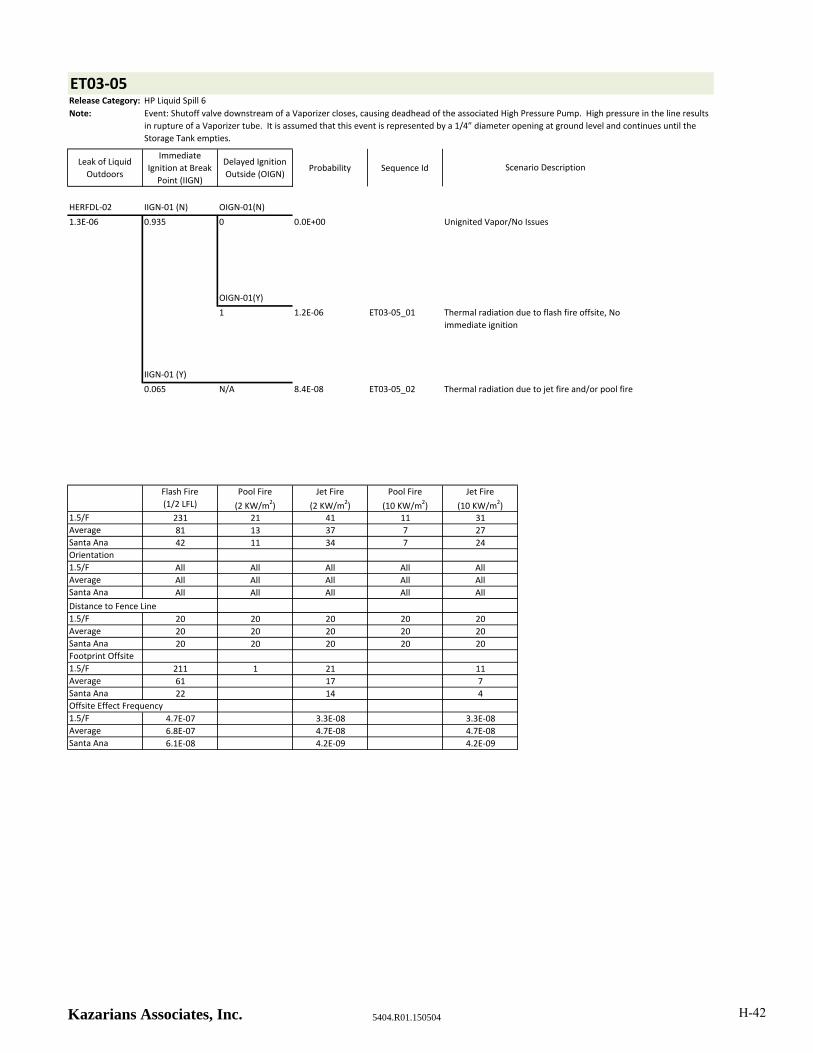
ET03‐05Release Category: HP Liquid Spill 6
Note:
Leak of Liquid
Outdoors
Immediate
Ignition at Break
Point (IIGN)
Delayed Ignition
Outside (OIGN)Probability Sequence Id
HERFDL‐02 IIGN‐01 (N) OIGN‐01(N)
1.3E‐06 0.935 0 0.0E+00 Unignited Vapor/No Issues
OIGN‐01(Y)
1 1.2E‐06 ET03‐05_01
IIGN‐01 (Y)
0.065 N/A 8.4E‐08 ET03‐05_02
Flash Fire
(1/2 LFL)
Pool Fire
(2 KW/m2)
Jet Fire
(2 KW/m2)
Pool Fire
(10 KW/m2)
Jet Fire
(10 KW/m2)1.5/F 231 21 41 11 31
Average 81 13 37 7 27
Santa Ana 42 11 34 7 24
Orientation
1.5/F All All All All All
Average All All All All All
Santa Ana All All All All All
Distance to Fence Line
1.5/F 20 20 20 20 20
Average 20 20 20 20 20
Santa Ana 20 20 20 20 20
Footprint Offsite
1.5/F 211 1 21 11
Average 61 17 7
Santa Ana 22 14 4
Offsite Effect Frequency
1.5/F 4.7E‐07 3.3E‐08 3.3E‐08
Average 6.8E‐07 4.7E‐08 4.7E‐08
Santa Ana 6.1E‐08 4.2E‐09 4.2E‐09
Event: Shutoff valve downstream of a Vaporizer closes, causing deadhead of the associated High Pressure Pump. High pressure in the line results
in rupture of a Vaporizer tube. It is assumed that this event is represented by a 1/4” diameter opening at ground level and continues until the
Storage Tank empties.
Scenario Description
Thermal radiation due to flash fire offsite, No
immediate ignition
Thermal radiation due to jet fire and/or pool fire
Kazarians Associates, Inc. 5404.R01.150504 H-42

ET03‐06Release Category: HP Liquid Spill 4
Note:
Leak of Liquid
Outdoors
Immediate
Ignition at Break
Point (IIGN)
Delayed Ignition
Outside (OIGN)Probability Sequence Id
HERFDL‐02 IIGN‐01 (N) OIGN‐01(N)
1.3E‐06 0.935 0 0.0E+00 Unignited Vapor/No Issues
OIGN‐01(Y)
1 1.2E‐06 ET03‐06_01
IIGN‐01 (Y)
0.065 N/A 8.4E‐08 ET03‐06_02
Flash Fire
(1/2 LFL)
Pool Fire
(2 KW/m2)
Jet Fire
(2 KW/m2)
Pool Fire
(10 KW/m2)
Jet Fire
(10 KW/m2)1.5/F 885 308 257 154 194
Average 467 324 239 154 170
Santa Ana 443 251 220 146 150
Orientation
1.5/F All All All All All
Average All All All All All
Santa Ana All All All All All
Distance to Fence Line
1.5/F 20 20 20 20 20
Average 20 20 20 20 20
Santa Ana 20 20 20 20 20
Footprint Offsite
1.5/F 865 288 237 134 174
Average 447 304 219 134 150
Santa Ana 423 231 200 126 130
Offsite Effect Frequency
1.5/F 4.7E‐07 3.3E‐08 3.3E‐08
Average 6.8E‐07 4.7E‐08 4.7E‐08
Santa Ana 6.1E‐08 4.2E‐09 4.2E‐09
Event: 1” Pipe break outside near the Vaporizers. The release occurs downstream of the High Pressure Pumps. It is assumed that this event is
represented by a 1” diameter opening at ground level and continues until the Storage Tank empties.
Scenario Description
Thermal radiation due to flash fire offsite, No
immediate ignition
Thermal radiation due to jet fire and/or pool fire
Kazarians Associates, Inc. 5404.R01.150504 H-43
ET03‐07Release Category: HP Liquid Spill 6
Note:
Leak of Liquid
Outdoors
Immediate
Ignition at Break
Point (IIGN)
Delayed Ignition
Outside (OIGN)Probability Sequence Id
HERFDL‐02 IIGN‐01 (N) OIGN‐01(N)
1.3E‐06 0.935 0 0.0E+00 Unignited Vapor/No Issues
OIGN‐01(Y)
1 1.2E‐06 ET03‐07_01
IIGN‐01 (Y)
0.065 N/A 8.4E‐08 ET03‐07_02
Flash Fire
(1/2 LFL)
Pool Fire
(2 KW/m2)
Jet Fire
(2 KW/m2)
Pool Fire
(10 KW/m2)
Jet Fire
(10 KW/m2)1.5/F 231 21 41 11 31
Average 81 13 37 7 27
Santa Ana 42 11 34 7 24
Orientation
1.5/F All All All All All
Average All All All All All
Santa Ana All All All All All
Distance to Fence Line
1.5/F 20 20 20 20 20
Average 20 20 20 20 20
Santa Ana 20 20 20 20 20
Footprint Offsite
1.5/F 211 1 21 11
Average 61 17 7
Santa Ana 22 14 4
Offsite Effect Frequency
1.5/F 4.7E‐07 3.3E‐08 3.3E‐08
Average 6.8E‐07 4.7E‐08 4.7E‐08
Santa Ana 6.1E‐08 4.2E‐09 4.2E‐09
Event: Shutoff valve downstream of a Vaporizer closes, causing deadhead of the associated High Pressure Pump. High pressure in the line results
in rupture of a Vaporizer tube. It is assumed that this event is represented by a 1/4” diameter opening at ground level and continues until the
Storage Tank empties.
Scenario Description
Thermal radiation due to flash fire offsite, No
immediate ignition
Thermal radiation due to jet fire and/or pool fire
Kazarians Associates, Inc. 5404.R01.150504 H-44

ET03‐08Release Category: HP Liquid Spill 4
Note:
Leak of Liquid
Outdoors
Immediate
Ignition at Break
Point (IIGN)
Delayed Ignition
Outside (OIGN)Probability Sequence Id
HERFDL‐02 IIGN‐01 (N) OIGN‐01(N)
1.3E‐06 0.935 0 0.0E+00 Unignited Vapor/No Issues
OIGN‐01(Y)
1 1.2E‐06 ET03‐08_01
IIGN‐01 (Y)
0.065 N/A 8.4E‐08 ET03‐08_02
Flash Fire
(1/2 LFL)
Pool Fire
(2 KW/m2)
Jet Fire
(2 KW/m2)
Pool Fire
(10 KW/m2)
Jet Fire
(10 KW/m2)1.5/F 885 308 257 154 194
Average 467 324 239 154 170
Santa Ana 443 251 220 146 150
Orientation
1.5/F All All All All All
Average All All All All All
Santa Ana All All All All All
Distance to Fence Line
1.5/F 20 20 20 20 20
Average 20 20 20 20 20
Santa Ana 20 20 20 20 20
Footprint Offsite
1.5/F 865 288 237 134 174
Average 447 304 219 134 150
Santa Ana 423 231 200 126 130
Offsite Effect Frequency
1.5/F 4.7E‐07 3.3E‐08 3.3E‐08
Average 6.8E‐07 4.7E‐08 4.7E‐08
Santa Ana 6.1E‐08 4.2E‐09 4.2E‐09
Event: 1” Pipe break outside near the Vaporizers. The release occurs downstream of the High Pressure Pumps. It is assumed that this event is
represented by a 1” diameter opening at ground level and continues until the Storage Tank empties.
Scenario Description
Thermal radiation due to flash fire offsite, No
immediate ignition
Thermal radiation due to jet fire and/or pool fire
Kazarians Associates, Inc. 5404.R01.150504 H-45

ET04‐01Release Category: Tanker Spill 1
Note:
Release of Liquid
During LNG
Delivery
Immediate
Ignition Outside
(IIGN)
Delayed Ignition
Offsite (OIGN)Probability Sequence Id
HB‐1 IIGN‐05(N) OIGN‐01(N)
3.6E‐06 9.00E‐01 0 0.0E+00 Unignited Vapor/No Issues
OIGN‐01(Y)
1 3.2E‐06 ET04‐01_01
IIGN‐05(Y)
0.1 N/A 3.6E‐07 ET04‐01_02
Flash Fire
(1/2 LFL)
Pool Fire
(2 KW/m2)
Jet Fire
(2 KW/m2)
Pool Fire
(10 KW/m2)
Jet Fire
(10 KW/m2)1.5/F 1,158 220 288 110 216
Average 430 230 272 122 192
Santa Ana 477 207 251 122 169
Orientation
1.5/F All All All All All
Average All All All All All
Santa Ana All All All All All
Distance to Fence Line
1.5/F 65 65 65 65 65
Average 65 65 65 65 65
Santa Ana 65 65 65 65 65
Footprint Offsite
1.5/F 1093 155 223 45 151
Average 365 165 207 57 127
Santa Ana 412 142 186 57 104
Offsite Effect Frequency
1.5/F 1.3E‐06 1.4E‐07 1.4E‐07
Average 1.8E‐06 2.0E‐07 2.0E‐07
Santa Ana 1.6E‐07 1.8E‐08 1.8E‐08
Event: Hose failure during LNG unloading with the driver activating the emergency shutdown system. It is
assumed that this event is represented by a 3” diameter opening at ground level and for a duration of 30
seconds.
Scenario Description
Thermal radiation due to flash fire offsite
Thermal radiation due to pool and/or jet fire onsite
Kazarians Associates, Inc. 5404.R01.150504 H-46
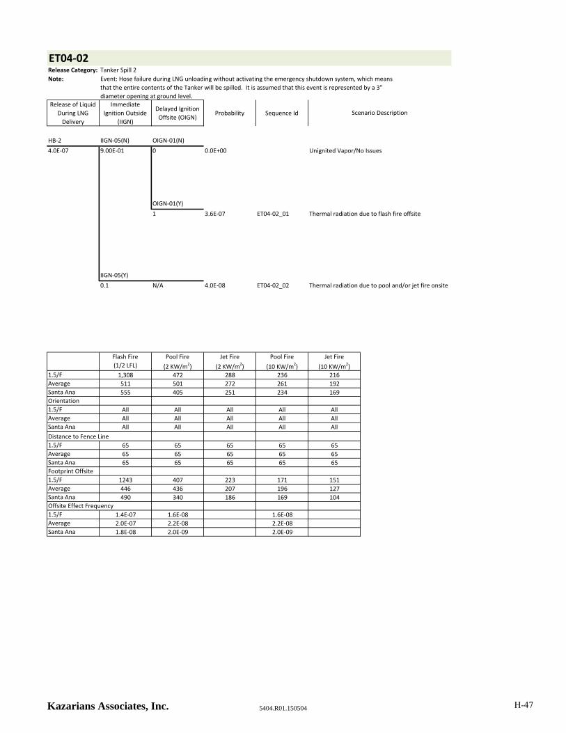
ET04‐02Release Category: Tanker Spill 2
Note:
Release of Liquid
During LNG
Delivery
Immediate
Ignition Outside
(IIGN)
Delayed Ignition
Offsite (OIGN)Probability Sequence Id
HB‐2 IIGN‐05(N) OIGN‐01(N)
4.0E‐07 9.00E‐01 0 0.0E+00 Unignited Vapor/No Issues
OIGN‐01(Y)
1 3.6E‐07 ET04‐02_01
IIGN‐05(Y)
0.1 N/A 4.0E‐08 ET04‐02_02
Flash Fire
(1/2 LFL)
Pool Fire
(2 KW/m2)
Jet Fire
(2 KW/m2)
Pool Fire
(10 KW/m2)
Jet Fire
(10 KW/m2)1.5/F 1,308 472 288 236 216
Average 511 501 272 261 192
Santa Ana 555 405 251 234 169
Orientation
1.5/F All All All All All
Average All All All All All
Santa Ana All All All All All
Distance to Fence Line
1.5/F 65 65 65 65 65
Average 65 65 65 65 65
Santa Ana 65 65 65 65 65
Footprint Offsite
1.5/F 1243 407 223 171 151
Average 446 436 207 196 127
Santa Ana 490 340 186 169 104
Offsite Effect Frequency
1.5/F 1.4E‐07 1.6E‐08 1.6E‐08
Average 2.0E‐07 2.2E‐08 2.2E‐08
Santa Ana 1.8E‐08 2.0E‐09 2.0E‐09
Event: Hose failure during LNG unloading without activating the emergency shutdown system, which means
that the entire contents of the Tanker will be spilled. It is assumed that this event is represented by a 3”
diameter opening at ground level.
Scenario Description
Thermal radiation due to flash fire offsite
Thermal radiation due to pool and/or jet fire onsite
Kazarians Associates, Inc. 5404.R01.150504 H-47

ET04‐03Release Category: Tanker Spill 9
Note:
Release of Liquid
During LNG
Delivery
Immediate
Ignition Outside
(IIGN)
Delayed Ignition
Offsite (OIGN)Probability Sequence Id
TR IIGN‐05(N) OIGN‐01(N)
5.0E‐07 9.00E‐01 0 0.0E+00 Unignited Vapor/No Issues
OIGN‐01(Y)
1 4.5E‐07 ET04‐03_01
IIGN‐05(Y)
0.1 N/A 5.0E‐08 ET04‐03_02
Flash Fire
(1/2 LFL)
Pool Fire
(2 KW/m2)
Jet Fire
(2 KW/m2)
Pool Fire
(10 KW/m2)
Jet Fire
(10 KW/m2)1.5/F 5,634 932 1522 472 1117
Average 2234 1024 1479 527 1014
Santa Ana 1962 933 1354 529 894
Orientation
1.5/F All All All All All
Average All All All All All
Santa Ana All All All All All
Distance to Fence Line
1.5/F 65 65 65 65 65
Average 65 65 65 65 65
Santa Ana 65 65 65 65 65
Footprint Offsite
1.5/F 5569 867 1457 407 1052
Average 2169 959 1414 462 949
Santa Ana 1897 868 1289 464 829
Offsite Effect Frequency
1.5/F 1.8E‐07 2.0E‐08 2.0E‐08
Average 2.5E‐07 2.8E‐08 2.8E‐08
Santa Ana 2.3E‐08 2.5E‐09 2.5E‐09
Event: Catastrophic rupture of an LNG Tanker Truck while onsite, due to mechanical impact or failure. It is
assumed that this event is represented by a 12" diameter opening at ground level, and continues until the
Tanker empties.
Scenario Description
Thermal radiation due to flash fire offsite
Thermal radiation due to pool and/or jet fire onsite
Kazarians Associates, Inc. 5404.R01.150504 H-48

ET05‐01Release Category: HP Vapor Release 8
Note:
Rupture of a
Buffer Tank
Immediate
Ignition Upon
Release (IIGN)
Delayed Ignition
Offsite (OIGN)Probability Sequence Id
PBL IIGN‐06(N) OIGN‐01(N)
4.9E‐08 5.0E‐01 0 0.0E+00 Unignited Vapor/No Issues
OIGN‐01(Y)
1 2.5E‐08 ET05‐01_01
IIGN‐06(Y)
5.0E‐01 N/A 2.5E‐08 ET05‐01_02
Flash Fire
(1/2 LFL)
Pool Fire
(2 KW/m2)
Jet Fire
(2 KW/m2)
Pool Fire
(10 KW/m2)
Jet Fire
(10 KW/m2)
1.5/F 1,506 4,773 2,918
Average 2,152 5,332 3,124
Santa Ana 3,620 4,668 3,117
Orientation
1.5/F All All All All All
Average All All All All All
Santa Ana All All All All All
Distance to Fence Line
1.5/F 25 25 25 25 25
Average 25 25 25 25 25
Santa Ana 25 25 25 25 25
Footprint Offsite
1.5/F 1481 4748 2893
Average 2127 5307 3099
Santa Ana 3595 4643 3092
Offsite Effect Frequency
1.5/F 9.6E‐09 9.6E‐09 9.6E‐09
Average 1.4E‐08 1.4E‐08 1.4E‐08
Santa Ana 1.2E‐09 1.2E‐09 1.2E‐09
Event: Catastrophic failure of a Buffer Tank due to increased pressure from an external fire. It is assumed that
this event is represented by a 12” diameter opening at ground level at 11,000 psi, and continues until all 6
Buffer Tanks empty.
Scenario Description
Thermal radiation due to flash fire outside, No
ignition inside, no flash back into room
Thermal radiation due to jet fire
Kazarians Associates, Inc. 5404.R01.150504 H-49
ET06‐01Release Category: HP Vapor Release 1
Note:
Release of CNG
Outdoors
Immediate
Ignition Upon
Release (IIGN)
Delayed Ignition
Offsite (OIGN)Probability Sequence Id
VTR‐01 IIGN‐02(N) OIGN‐01(N)
1.0E‐06 9.8E‐01 0 0.0E+00 Unignited Vapor/No Issues
OIGN‐01(Y)
1 9.8E‐07 ET06‐01_01
IIGN‐02(Y)
2.0E‐02 N/A 2.0E‐08 ET06‐01_02
Flash Fire
(1/2 LFL)
Pool Fire
(2 KW/m2)
Jet Fire
(2 KW/m2)
Pool Fire
(10 KW/m2)
Jet Fire
(10 KW/m2)
1.5/F 189 34 28
Average 83 33 27
Santa Ana 50 30 27
Orientation
1.5/F All All All All All
Average All All All All All
Santa Ana All All All All All
Distance to Fence Line
1.5/F 20 20 20 20 20
Average 20 20 20 20 20
Santa Ana 20 20 20 20 20
Footprint Offsite
1.5/F 169 14 8
Average 63 13 7
Santa Ana 30 10 7
Offsite Effect Frequency
1.5/F 3.8E‐07 7.8E‐09 7.8E‐09
Average 5.5E‐07 1.1E‐08 1.1E‐08
Santa Ana 4.9E‐08 1.0E‐09 1.0E‐09
Event: Break of a 1/4" vaporizer coil. It is assumed that this event is represented by a 1/4” diameter opening at
ground level, and continues for 1 hour.
Scenario Description
Thermal radiation due to flash fire offsite, No
immediate ignition
Thermal radiation due to jet fire
Kazarians Associates, Inc. 5404.R01.150504 H-50

ET06‐02Release Category: HP Vapor Release 2
Note:
Release of CNG
Outdoors
Immediate
Ignition Upon
Release (IIGN)
Delayed Ignition
Offsite (OIGN)Probability Sequence Id
VTR‐01 IIGN‐02(N) OIGN‐01(N)
1.0E‐06 9.8E‐01 0 0.0E+00 Unignited Vapor/No Issues
OIGN‐01(Y)
1 9.8E‐07 ET06‐02_01
IIGN‐02(Y)
2.0E‐02 N/A 2.0E‐08 ET06‐02_02
Flash Fire
(1/2 LFL)
Pool Fire
(2 KW/m2)
Jet Fire
(2 KW/m2)
Pool Fire
(10 KW/m2)
Jet Fire
(10 KW/m2)
1.5/F 189 34 28
Average 83 33 27
Santa Ana 50 30 27
Orientation
1.5/F All All All All All
Average All All All All All
Santa Ana All All All All All
Distance to Fence Line
1.5/F 20 20 20 20 20
Average 20 20 20 20 20
Santa Ana 20 20 20 20 20
Footprint Offsite
1.5/F 169 14 8
Average 63 13 7
Santa Ana 30 10 7
Offsite Effect Frequency
1.5/F 3.8E‐07 7.8E‐09 7.8E‐09
Average 5.5E‐07 1.1E‐08 1.1E‐08
Santa Ana 4.9E‐08 1.0E‐09 1.0E‐09
Event: Break of a 1/4" vaporizer coil. It is assumed that this event is represented by a 1/4” diameter opening at
ground level and continues until the Storage Tank empties.
Scenario Description
Thermal radiation due to flash fire offsite, No
immediate ignition
Thermal radiation due to jet fire
Kazarians Associates, Inc. 5404.R01.150504 H-51

ET06‐03Release Category: HP Vapor Release 3
Note:
Release of CNG
Outdoors
Immediate
Ignition Upon
Release (IIGN)
Delayed Ignition
Offsite (OIGN)Probability Sequence Id
PBSCNG IIGN‐03(N) OIGN‐01(N)
2.5E‐06 9.6E‐01 0 0.0E+00 Unignited Vapor/No Issues
OIGN‐01(Y)
1 2.4E‐06 ET06‐03_01
IIGN‐03(Y)
4.0E‐02 N/A 1.0E‐07 ET06‐03_02
Flash Fire
(1/2 LFL)
Pool Fire
(2 KW/m2)
Jet Fire
(2 KW/m2)
Pool Fire
(10 KW/m2)
Jet Fire
(10 KW/m2)
1.5/F 811 167 74
Average 518 176 78
Santa Ana 272 166 75
Orientation
1.5/F All All All All All
Average All All All All All
Santa Ana All All All All All
Distance to Fence Line
1.5/F 10 10 10 10 10
Average 10 10 10 10 10
Santa Ana 10 10 10 10 10
Footprint Offsite
1.5/F 801 157 64
Average 508 166 68
Santa Ana 262 156 65
Offsite Effect Frequency
1.5/F 9.4E‐07 3.9E‐08 3.9E‐08
Average 1.3E‐06 5.6E‐08 5.6E‐08
Santa Ana 1.2E‐07 5.0E‐09 5.0E‐09
Event: 1” Pipe break downstream of the Vaporizers. It is assumed that this event is represented by a 1”
diameter opening at ground level and continues for 1 hour.
Scenario Description
Thermal radiation due to flash fire offsite, No
immediate ignition
Thermal radiation due to jet fire
Kazarians Associates, Inc. 5404.R01.150504 H-52

ET06‐04Release Category: HP Vapor Release 4
Note:
Release of CNG
Outdoors
Immediate
Ignition Upon
Release (IIGN)
Delayed Ignition
Offsite (OIGN)Probability Sequence Id
PBSCNG IIGN‐03(N) OIGN‐01(N)
2.5E‐06 9.6E‐01 0 0.0E+00 Unignited Vapor/No Issues
OIGN‐01(Y)
1 2.4E‐06 ET06‐04_01
IIGN‐03(Y)
4.0E‐02 N/A 1.0E‐07 ET06‐04_02
Flash Fire
(1/2 LFL)
Pool Fire
(2 KW/m2)
Jet Fire
(2 KW/m2)
Pool Fire
(10 KW/m2)
Jet Fire
(10 KW/m2)
1.5/F 811 167 74
Average 518 176 78
Santa Ana 272 166 75
Orientation
1.5/F All All All All All
Average All All All All All
Santa Ana All All All All All
Distance to Fence Line
1.5/F 10 10 10 10 10
Average 10 10 10 10 10
Santa Ana 10 10 10 10 10
Footprint Offsite
1.5/F 801 157 64
Average 508 166 68
Santa Ana 262 156 65
Offsite Effect Frequency
1.5/F 9.4E‐07 3.9E‐08 3.9E‐08
Average 1.3E‐06 5.6E‐08 5.6E‐08
Santa Ana 1.2E‐07 5.0E‐09 5.0E‐09
Event: 1” Pipe break downstream of the Vaporizers. It is assumed that this event is represented by a 1”
diameter opening at ground level and continues until the Storage Tank empties.
Scenario Description
Thermal radiation due to flash fire offsite, No
immediate ignition
Thermal radiation due to jet fire
Kazarians Associates, Inc. 5404.R01.150504 H-53

ET06‐05Release Category: Bus Fueling Release 1
Note:
Release of CNG
Outdoors
Immediate
Ignition Upon
Release (IIGN)
Delayed Ignition
Offsite (OIGN)Probability Sequence Id
HB‐1 IIGN‐03(N) OIGN‐01(N)
3.6E‐06 9.6E‐01 0 0.0E+00 Unignited Vapor/No Issues
OIGN‐01(Y)
1 3.5E‐06 ET06‐05_01
IIGN‐03(Y)
4.0E‐02 N/A 1.4E‐07 ET06‐05_02
Flash Fire
(1/2 LFL)
Pool Fire
(2 KW/m2)
Jet Fire
(2 KW/m2)
Pool Fire
(10 KW/m2)
Jet Fire
(10 KW/m2)
1.5/F 91 282 191
Average 569 286 196
Santa Ana 334 272 211
Orientation
1.5/F All All All All All
Average All All All All All
Santa Ana From the North From the North From the North From the North From the North
Distance to Fence Line
1.5/F 25 25 25 25 25
Average 25 25 25 25 25
Santa Ana 300 300 300 300 300
Footprint Offsite
1.5/F 66 257 166
Average 544 261 171
Santa Ana 34
Offsite Effect Frequency
1.5/F 1.3E‐06 5.6E‐08 5.6E‐08
Average 1.9E‐06 8.1E‐08 8.1E‐08
Santa Ana 1.7E‐07
Event: Hose failure during bus fueling with the driver activating the emergency shutdown system. It is assumed
that this event is represented by a 1” diameter opening at ground level, for a duration of 30 seconds.
Scenario Description
Thermal radiation due to flash fire offsite, No
immediate ignition
Thermal radiation due to jet fire
Kazarians Associates, Inc. 5404.R01.150504 H-54
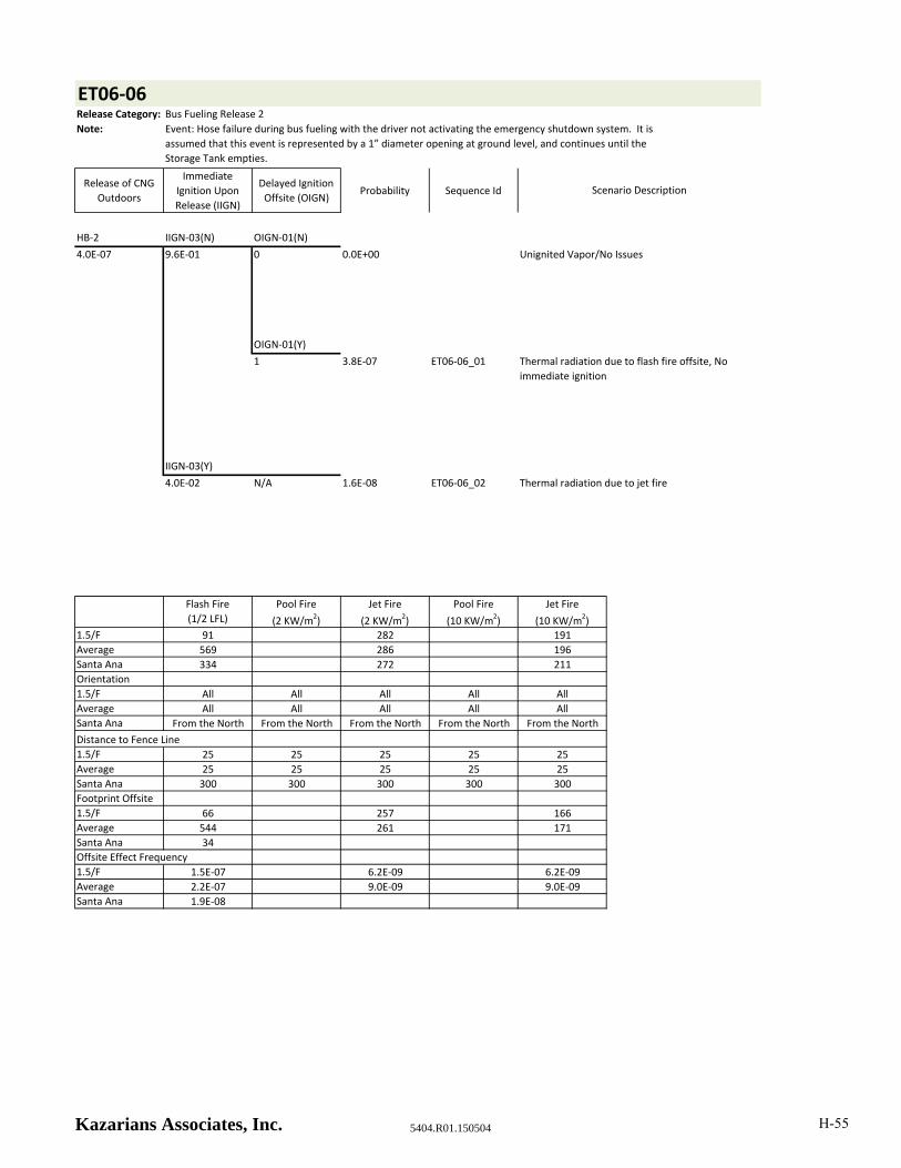
ET06‐06Release Category: Bus Fueling Release 2
Note:
Release of CNG
Outdoors
Immediate
Ignition Upon
Release (IIGN)
Delayed Ignition
Offsite (OIGN)Probability Sequence Id
HB‐2 IIGN‐03(N) OIGN‐01(N)
4.0E‐07 9.6E‐01 0 0.0E+00 Unignited Vapor/No Issues
OIGN‐01(Y)
1 3.8E‐07 ET06‐06_01
IIGN‐03(Y)
4.0E‐02 N/A 1.6E‐08 ET06‐06_02
Flash Fire
(1/2 LFL)
Pool Fire
(2 KW/m2)
Jet Fire
(2 KW/m2)
Pool Fire
(10 KW/m2)
Jet Fire
(10 KW/m2)
1.5/F 91 282 191
Average 569 286 196
Santa Ana 334 272 211
Orientation
1.5/F All All All All All
Average All All All All All
Santa Ana From the North From the North From the North From the North From the North
Distance to Fence Line
1.5/F 25 25 25 25 25
Average 25 25 25 25 25
Santa Ana 300 300 300 300 300
Footprint Offsite
1.5/F 66 257 166
Average 544 261 171
Santa Ana 34
Offsite Effect Frequency
1.5/F 1.5E‐07 6.2E‐09 6.2E‐09
Average 2.2E‐07 9.0E‐09 9.0E‐09
Santa Ana 1.9E‐08
Event: Hose failure during bus fueling with the driver not activating the emergency shutdown system. It is
assumed that this event is represented by a 1” diameter opening at ground level, and continues until the
Storage Tank empties.
Scenario Description
Thermal radiation due to flash fire offsite, No
immediate ignition
Thermal radiation due to jet fire
Kazarians Associates, Inc. 5404.R01.150504 H-55
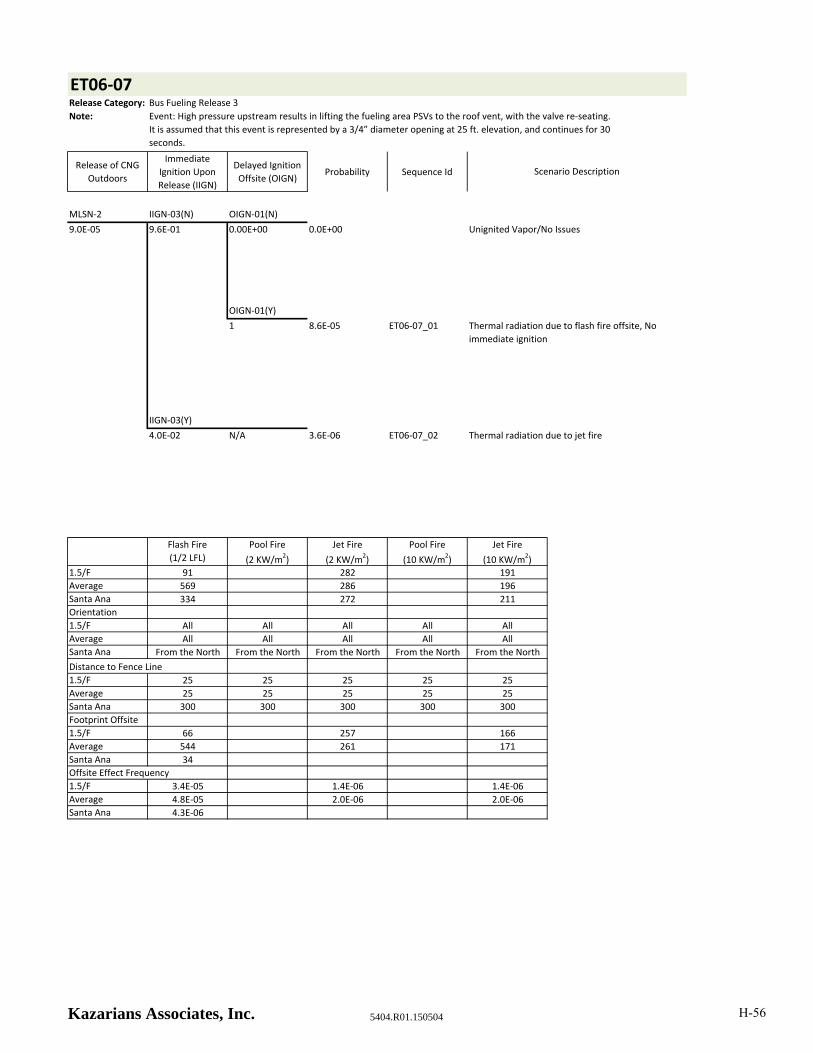
ET06‐07Release Category: Bus Fueling Release 3
Note:
Release of CNG
Outdoors
Immediate
Ignition Upon
Release (IIGN)
Delayed Ignition
Offsite (OIGN)Probability Sequence Id
MLSN‐2 IIGN‐03(N) OIGN‐01(N)
9.0E‐05 9.6E‐01 0.00E+00 0.0E+00 Unignited Vapor/No Issues
OIGN‐01(Y)
1 8.6E‐05 ET06‐07_01
IIGN‐03(Y)
4.0E‐02 N/A 3.6E‐06 ET06‐07_02
Flash Fire
(1/2 LFL)
Pool Fire
(2 KW/m2)
Jet Fire
(2 KW/m2)
Pool Fire
(10 KW/m2)
Jet Fire
(10 KW/m2)
1.5/F 91 282 191
Average 569 286 196
Santa Ana 334 272 211
Orientation
1.5/F All All All All All
Average All All All All All
Santa Ana From the North From the North From the North From the North From the North
Distance to Fence Line
1.5/F 25 25 25 25 25
Average 25 25 25 25 25
Santa Ana 300 300 300 300 300
Footprint Offsite
1.5/F 66 257 166
Average 544 261 171
Santa Ana 34
Offsite Effect Frequency
1.5/F 3.4E‐05 1.4E‐06 1.4E‐06
Average 4.8E‐05 2.0E‐06 2.0E‐06
Santa Ana 4.3E‐06
Event: High pressure upstream results in lifting the fueling area PSVs to the roof vent, with the valve re‐seating.
It is assumed that this event is represented by a 3/4” diameter opening at 25 ft. elevation, and continues for 30
seconds.
Scenario Description
Thermal radiation due to flash fire offsite, No
immediate ignition
Thermal radiation due to jet fire
Kazarians Associates, Inc. 5404.R01.150504 H-56
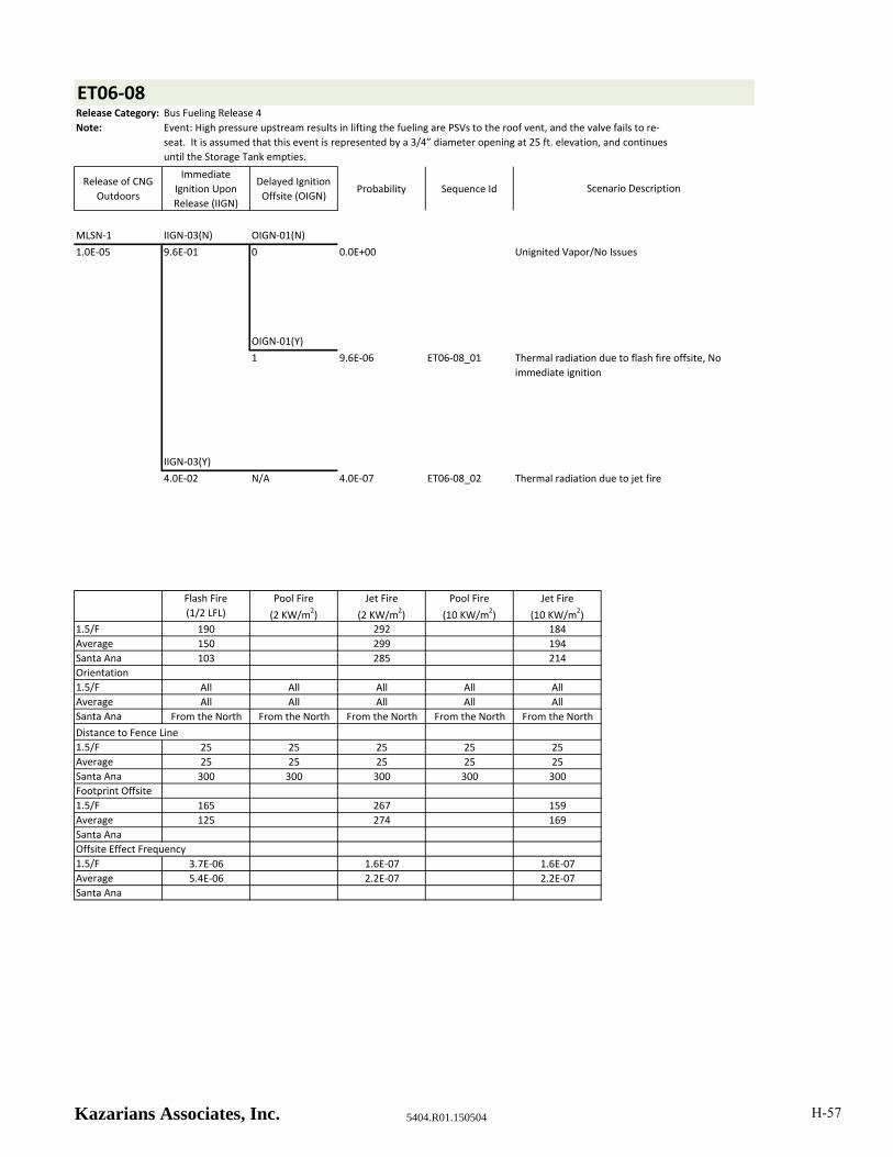
ET06‐08Release Category: Bus Fueling Release 4
Note:
Release of CNG
Outdoors
Immediate
Ignition Upon
Release (IIGN)
Delayed Ignition
Offsite (OIGN)Probability Sequence Id
MLSN‐1 IIGN‐03(N) OIGN‐01(N)
1.0E‐05 9.6E‐01 0 0.0E+00 Unignited Vapor/No Issues
OIGN‐01(Y)
1 9.6E‐06 ET06‐08_01
IIGN‐03(Y)
4.0E‐02 N/A 4.0E‐07 ET06‐08_02
Flash Fire
(1/2 LFL)
Pool Fire
(2 KW/m2)
Jet Fire
(2 KW/m2)
Pool Fire
(10 KW/m2)
Jet Fire
(10 KW/m2)
1.5/F 190 292 184
Average 150 299 194
Santa Ana 103 285 214
Orientation
1.5/F All All All All All
Average All All All All All
Santa Ana From the North From the North From the North From the North From the North
Distance to Fence Line
1.5/F 25 25 25 25 25
Average 25 25 25 25 25
Santa Ana 300 300 300 300 300
Footprint Offsite
1.5/F 165 267 159
Average 125 274 169
Santa Ana
Offsite Effect Frequency
1.5/F 3.7E‐06 1.6E‐07 1.6E‐07
Average 5.4E‐06 2.2E‐07 2.2E‐07
Santa Ana
Event: High pressure upstream results in lifting the fueling are PSVs to the roof vent, and the valve fails to re‐
seat. It is assumed that this event is represented by a 3/4” diameter opening at 25 ft. elevation, and continues
until the Storage Tank empties.
Scenario Description
Thermal radiation due to flash fire offsite, No
immediate ignition
Thermal radiation due to jet fire
Kazarians Associates, Inc. 5404.R01.150504 H-57

ET06‐09Release Category: Bus Fueling Release 5
Note:
Release of CNG
Outdoors
Immediate
Ignition Upon
Release (IIGN)
Delayed Ignition
Offsite (OIGN)Probability Sequence Id
PSVL IIGN‐03(N) OIGN‐02(N)
2.0E‐05 9.6E‐01 2.50E‐01 4.8E‐06 Unignited Vapor/No Issues
OIGN‐01(Y)
0.75 1.4E‐05 ET06‐09_01
IIGN‐03(Y)
4.0E‐02 N/A 8.0E‐07 ET06‐09_02
Flash Fire
(1/2 LFL)
Pool Fire
(2 KW/m2)
Jet Fire
(2 KW/m2)
Pool Fire
(10 KW/m2)
Jet Fire
(10 KW/m2)
1.5/F 190 292 184
Average 150 299 194
Santa Ana 103 285 214
Orientation
1.5/F All All All All All
Average All All All All All
Santa Ana From the North From the North From the North From the North From the North
Distance to Fence Line
1.5/F 25 25 25 25 25
Average 25 25 25 25 25
Santa Ana 300 300 300 300 300
Footprint Offsite
1.5/F 165 267 159
Average 125 274 169
Santa Ana
Offsite Effect Frequency
1.5/F 5.6E‐06 3.1E‐07 3.1E‐07
Average 8.1E‐06 4.5E‐07 4.5E‐07
Santa Ana
Event: Spurious lift of the PSV on a Bus Fueling Station. It is assumed that this event is represented by a 3/4”
diameter opening at 25 ft. elevation and continues until the Storage Tank empties.
Scenario Description
Thermal radiation due to flash fire offsite, No
immediate ignition
Thermal radiation due to jet fire
Kazarians Associates, Inc. 5404.R01.150504 H-58
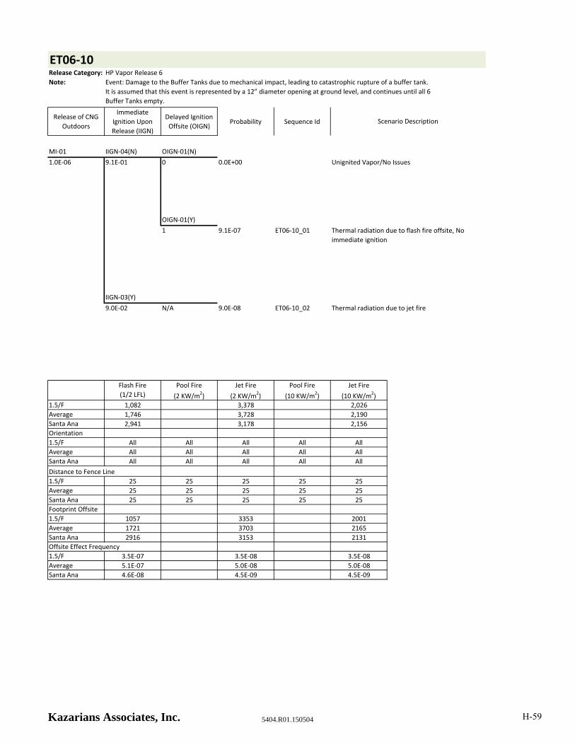
ET06‐10Release Category: HP Vapor Release 6
Note:
Release of CNG
Outdoors
Immediate
Ignition Upon
Release (IIGN)
Delayed Ignition
Offsite (OIGN)Probability Sequence Id
MI‐01 IIGN‐04(N) OIGN‐01(N)
1.0E‐06 9.1E‐01 0 0.0E+00 Unignited Vapor/No Issues
OIGN‐01(Y)
1 9.1E‐07 ET06‐10_01
IIGN‐03(Y)
9.0E‐02 N/A 9.0E‐08 ET06‐10_02
Flash Fire
(1/2 LFL)
Pool Fire
(2 KW/m2)
Jet Fire
(2 KW/m2)
Pool Fire
(10 KW/m2)
Jet Fire
(10 KW/m2)
1.5/F 1,082 3,378 2,026
Average 1,746 3,728 2,190
Santa Ana 2,941 3,178 2,156
Orientation
1.5/F All All All All All
Average All All All All All
Santa Ana All All All All All
Distance to Fence Line
1.5/F 25 25 25 25 25
Average 25 25 25 25 25
Santa Ana 25 25 25 25 25
Footprint Offsite
1.5/F 1057 3353 2001
Average 1721 3703 2165
Santa Ana 2916 3153 2131
Offsite Effect Frequency
1.5/F 3.5E‐07 3.5E‐08 3.5E‐08
Average 5.1E‐07 5.0E‐08 5.0E‐08
Santa Ana 4.6E‐08 4.5E‐09 4.5E‐09
Event: Damage to the Buffer Tanks due to mechanical impact, leading to catastrophic rupture of a buffer tank.
It is assumed that this event is represented by a 12” diameter opening at ground level, and continues until all 6
Buffer Tanks empty.
Scenario Description
Thermal radiation due to flash fire offsite, No
immediate ignition
Thermal radiation due to jet fire
Kazarians Associates, Inc. 5404.R01.150504 H-59

ET06‐11Release Category: HP Vapor Release 7
Note:
Release of CNG
Outdoors
Immediate
Ignition Upon
Release (IIGN)
Delayed Ignition
Offsite (OIGN)Probability Sequence Id
MI‐02 IIGN‐04(N) OIGN‐01(N)
2.0E‐06 9.1E‐01 0 0.0E+00 Unignited Vapor/No Issues
OIGN‐01(Y)
1 1.8E‐06 ET06‐11_01
IIGN‐03(Y)
9.0E‐02 N/A 1.8E‐07 ET06‐11_02
Flash Fire
(1/2 LFL)
Pool Fire
(2 KW/m2)
Jet Fire
(2 KW/m2)
Pool Fire
(10 KW/m2)
Jet Fire
(10 KW/m2)
1.5/F 228 664 416
Average 1,610 688 436
Santa Ana 890 620 444
Orientation
1.5/F All All All All All
Average All All All All All
Santa Ana All All All All All
Distance to Fence Line
1.5/F 25 25 25 25 25
Average 25 25 25 25 25
Santa Ana 25 25 25 25 25
Footprint Offsite
1.5/F 203 639 391
Average 1585 663 411
Santa Ana 865 595 419
Offsite Effect Frequency
1.5/F 7.1E‐07 7.0E‐08 7.0E‐08
Average 1.0E‐06 1.0E‐07 1.0E‐07
Santa Ana 9.1E‐08 9.0E‐09 9.0E‐09
Event: Damage to the Buffer Tanks due to mechanical impact, resulting in a puncture of one Tank. It is assumed
that this event is represented by a 2” diameter opening at ground level, and continues until all 6 Buffer Tanks
empty.
Scenario Description
Thermal radiation due to flash fire offsite, No
immediate ignition
Thermal radiation due to jet fire
Kazarians Associates, Inc. 5404.R01.150504 H-60

ET06‐12Release Category: HP Vapor Release 5
Note:
Release of CNG
Outdoors
Immediate
Ignition Upon
Release (IIGN)
Delayed Ignition
Offsite (OIGN)Probability Sequence Id
MI‐01 IIGN‐02(N) OIGN‐01(N)
1.0E‐07 9.8E‐01 0 0.0E+00 Unignited Vapor/No Issues
OIGN‐01(Y)
1 9.8E‐08 ET06‐12_01
IIGN‐03(Y)
2.0E‐02 N/A 2.0E‐09 ET06‐12_02
Flash Fire
(1/2 LFL)
Pool Fire
(2 KW/m2)
Jet Fire
(2 KW/m2)
Pool Fire
(10 KW/m2)
Jet Fire
(10 KW/m2)
1.5/F 54 121 87
Average 246 120 88
Santa Ana 151 114 95
Orientation
1.5/F All All All All All
Average All All All All All
Santa Ana All All All All All
Distance to Fence Line
1.5/F 10 10 10 10 10
Average 10 10 10 10 10
Santa Ana 10 10 10 10 10
Footprint Offsite
1.5/F 44 111 77
Average 236 110 78
Santa Ana 141 104 85
Offsite Effect Frequency
1.5/F 3.8E‐08 7.8E‐10 7.8E‐10
Average 5.5E‐08 1.1E‐09 1.1E‐09
Santa Ana 4.9E‐09 1.0E‐10 1.0E‐10
Event: Damage to the CNG piping along the north wall of the facility due to mechanical impact. It is assumed
that this event is represented by a 1” diameter opening at ground level, and continues until the Storage Tank
empties.
Scenario Description
Thermal radiation due to flash fire offsite, No
immediate ignition
Thermal radiation due to jet fire
Kazarians Associates, Inc. 5404.R01.150504 H-61
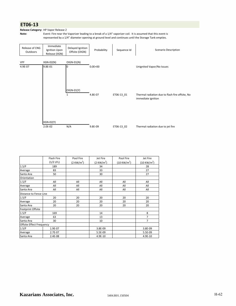
ET06‐13Release Category: HP Vapor Release 2
Note:
Release of CNG
Outdoors
Immediate
Ignition Upon
Release (IIGN)
Delayed Ignition
Offsite (OIGN)Probability Sequence Id
VFF IIGN‐02(N) OIGN‐01(N)
4.9E‐07 9.8E‐01 0 0.0E+00 Unignited Vapor/No Issues
OIGN‐01(Y)
1 4.8E‐07 ET06‐13_01
IIGN‐02(Y)
2.0E‐02 N/A 9.8E‐09 ET06‐13_02
Flash Fire
(1/2 LFL)
Pool Fire
(2 KW/m2)
Jet Fire
(2 KW/m2)
Pool Fire
(10 KW/m2)
Jet Fire
(10 KW/m2)
1.5/F 189 34 28
Average 83 33 27
Santa Ana 50 30 27
Orientation
1.5/F All All All All All
Average All All All All All
Santa Ana All All All All All
Distance to Fence Line
1.5/F 20 20 20 20 20
Average 20 20 20 20 20
Santa Ana 20 20 20 20 20
Footprint Offsite
1.5/F 169 14 8
Average 63 13 7
Santa Ana 30 10 7
Offsite Effect Frequency
1.5/F 1.9E‐07 3.8E‐09 3.8E‐09
Average 2.7E‐07 5.5E‐09 5.5E‐09
Santa Ana 2.4E‐08 4.9E‐10 4.9E‐10
Event: Fire near the Vaporizer leading to a break of a 1/4" vaporizer coil. It is assumed that this event is
represented by a 1/4” diameter opening at ground level and continues until the Storage Tank empties.
Scenario Description
Thermal radiation due to flash fire offsite, No
immediate ignition
Thermal radiation due to jet fire
Kazarians Associates, Inc. 5404.R01.150504 H-62

Table H8 - Hazard Zone - Flash Fire and 2 KW/m2 Thermal Radiation
Event Tree Distance (ft)Individual
Probability
Summed
ProbabilityPercentage
ET01‐09 3 2.0E‐08 2.2E‐04 0.0%
ET01‐11 3 4.9E‐08 2.2E‐04 0.0%
ET01‐07 7 7.8E‐07 2.2E‐04 0.0%
ET01‐04 9 1.0E‐06 2.2E‐04 0.4%
ET01‐05 9 1.0E‐06 2.2E‐04 0.8%
ET01‐08 9 2.2E‐07 2.2E‐04 1.3%
ET01‐10 9 5.5E‐07 2.2E‐04 1.4%
ET06‐01 10 1.0E‐09 2.2E‐04 1.7%
ET06‐02 10 1.0E‐09 2.2E‐04 1.7%
ET06‐13 10 4.9E‐10 2.2E‐04 1.7%
ET01‐06 11 7.8E‐07 2.2E‐04 1.7%
ET02‐11 11 2.4E‐06 2.2E‐04 2.0%
ET06‐01 13 1.1E‐08 2.1E‐04 3.1%
ET06‐02 13 1.1E‐08 2.1E‐04 3.1%
ET06‐13 13 5.5E‐09 2.1E‐04 3.1%
ET02‐13 14 4.7E‐07 2.1E‐04 3.1%
ET03‐01 14 4.2E‐09 2.1E‐04 3.3%
ET03‐05 14 4.2E‐09 2.1E‐04 3.3%
ET03‐07 14 4.2E‐09 2.1E‐04 3.3%
ET06‐01 14 7.8E‐09 2.1E‐04 3.3%
ET06‐02 14 7.8E‐09 2.1E‐04 3.3%
ET06‐13 14 3.8E‐09 2.1E‐04 3.3%
ET01‐08 15 2.0E‐08 2.1E‐04 3.3%
ET02‐14 15 3.6E‐08 2.1E‐04 3.3%
ET01‐10 15 4.9E‐08 2.1E‐04 3.3%
ET02‐14 17 2.5E‐08 2.1E‐04 3.4%
ET03‐01 17 4.7E‐08 2.1E‐04 3.4%
ET03‐05 17 4.7E‐08 2.1E‐04 3.4%
ET03‐07 17 4.7E‐08 2.1E‐04 3.4%
ET01‐07 18 1.1E‐06 2.1E‐04 3.4%
ET01‐04 21 1.5E‐06 2.1E‐04 3.9%
ET01‐05 21 1.5E‐06 2.1E‐04 4.6%
ET01‐07 21 1.0E‐07 2.1E‐04 5.3%
ET03‐01 21 3.3E‐08 2.1E‐04 5.3%
ET03‐05 21 3.3E‐08 2.1E‐04 5.3%
ET03‐07 21 3.3E‐08 2.1E‐04 5.3%
ET03‐01 22 6.1E‐08 2.1E‐04 5.3%
ET03‐05 22 6.1E‐08 2.1E‐04 5.4%
ET03‐07 22 6.1E‐08 2.1E‐04 5.4%
ET01‐06 25 1.1E‐06 2.1E‐04 5.4%
ET01‐04 27 1.3E‐07 2.1E‐04 5.9%
ET01‐05 27 1.3E‐07 2.1E‐04 6.0%
ET02‐14 29 4.7E‐08 2.1E‐04 6.1%
Kazarians Associates, Inc. 5404.R01.150504 H-63
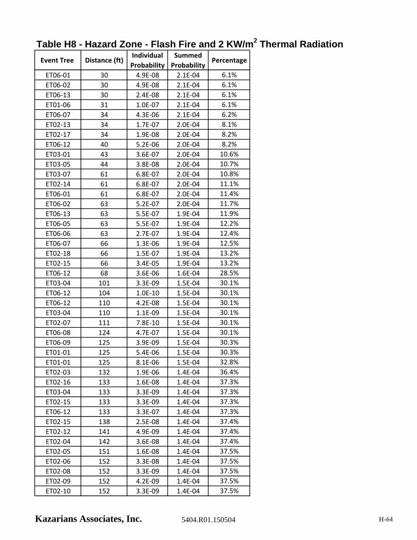
Table H8 - Hazard Zone - Flash Fire and 2 KW/m2 Thermal Radiation
Event Tree Distance (ft)Individual
Probability
Summed
ProbabilityPercentage
ET06‐01 30 4.9E‐08 2.1E‐04 6.1%
ET06‐02 30 4.9E‐08 2.1E‐04 6.1%
ET06‐13 30 2.4E‐08 2.1E‐04 6.1%
ET01‐06 31 1.0E‐07 2.1E‐04 6.1%
ET06‐07 34 4.3E‐06 2.1E‐04 6.2%
ET02‐13 34 1.7E‐07 2.0E‐04 8.1%
ET02‐17 34 1.9E‐08 2.0E‐04 8.2%
ET06‐12 40 5.2E‐06 2.0E‐04 8.2%
ET03‐01 43 3.6E‐07 2.0E‐04 10.6%
ET03‐05 44 3.8E‐08 2.0E‐04 10.7%
ET03‐07 61 6.8E‐07 2.0E‐04 10.8%
ET02‐14 61 6.8E‐07 2.0E‐04 11.1%
ET06‐01 61 6.8E‐07 2.0E‐04 11.4%
ET06‐02 63 5.2E‐07 2.0E‐04 11.7%
ET06‐13 63 5.5E‐07 1.9E‐04 11.9%
ET06‐05 63 5.5E‐07 1.9E‐04 12.2%
ET06‐06 63 2.7E‐07 1.9E‐04 12.4%
ET06‐07 66 1.3E‐06 1.9E‐04 12.5%
ET02‐18 66 1.5E‐07 1.9E‐04 13.2%
ET02‐15 66 3.4E‐05 1.9E‐04 13.2%
ET06‐12 68 3.6E‐06 1.6E‐04 28.5%
ET03‐04 101 3.3E‐09 1.5E‐04 30.1%
ET06‐12 104 1.0E‐10 1.5E‐04 30.1%
ET06‐12 110 4.2E‐08 1.5E‐04 30.1%
ET03‐04 110 1.1E‐09 1.5E‐04 30.1%
ET02‐07 111 7.8E‐10 1.5E‐04 30.1%
ET06‐08 124 4.7E‐07 1.5E‐04 30.1%
ET06‐09 125 3.9E‐09 1.5E‐04 30.3%
ET01‐01 125 5.4E‐06 1.5E‐04 30.3%
ET01‐01 125 8.1E‐06 1.5E‐04 32.8%
ET02‐03 132 1.9E‐06 1.4E‐04 36.4%
ET02‐16 133 1.6E‐08 1.4E‐04 37.3%
ET03‐04 133 3.3E‐09 1.4E‐04 37.3%
ET02‐15 133 3.3E‐09 1.4E‐04 37.3%
ET06‐12 133 3.3E‐07 1.4E‐04 37.3%
ET02‐15 138 2.5E‐08 1.4E‐04 37.4%
ET02‐12 141 4.9E‐09 1.4E‐04 37.4%
ET02‐04 142 3.6E‐08 1.4E‐04 37.4%
ET02‐05 151 1.6E‐08 1.4E‐04 37.5%
ET02‐06 152 3.3E‐08 1.4E‐04 37.5%
ET02‐08 152 3.3E‐09 1.4E‐04 37.5%
ET02‐09 152 4.2E‐09 1.4E‐04 37.5%
ET02‐10 152 3.3E‐09 1.4E‐04 37.5%
Kazarians Associates, Inc. 5404.R01.150504 H-64
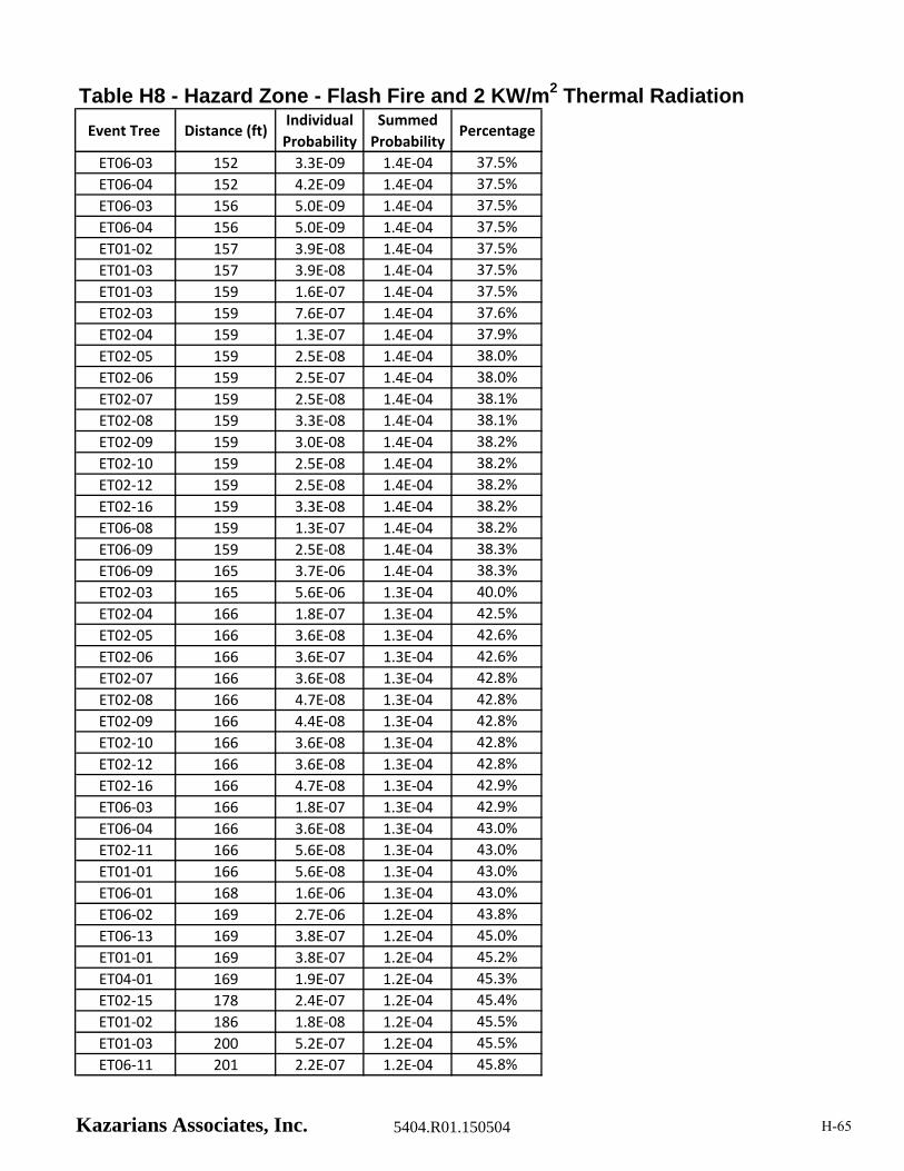
Table H8 - Hazard Zone - Flash Fire and 2 KW/m2 Thermal Radiation
Event Tree Distance (ft)Individual
Probability
Summed
ProbabilityPercentage
ET06‐03 152 3.3E‐09 1.4E‐04 37.5%
ET06‐04 152 4.2E‐09 1.4E‐04 37.5%
ET06‐03 156 5.0E‐09 1.4E‐04 37.5%
ET06‐04 156 5.0E‐09 1.4E‐04 37.5%
ET01‐02 157 3.9E‐08 1.4E‐04 37.5%
ET01‐03 157 3.9E‐08 1.4E‐04 37.5%
ET01‐03 159 1.6E‐07 1.4E‐04 37.5%
ET02‐03 159 7.6E‐07 1.4E‐04 37.6%
ET02‐04 159 1.3E‐07 1.4E‐04 37.9%
ET02‐05 159 2.5E‐08 1.4E‐04 38.0%
ET02‐06 159 2.5E‐07 1.4E‐04 38.0%
ET02‐07 159 2.5E‐08 1.4E‐04 38.1%
ET02‐08 159 3.3E‐08 1.4E‐04 38.1%
ET02‐09 159 3.0E‐08 1.4E‐04 38.2%
ET02‐10 159 2.5E‐08 1.4E‐04 38.2%
ET02‐12 159 2.5E‐08 1.4E‐04 38.2%
ET02‐16 159 3.3E‐08 1.4E‐04 38.2%
ET06‐08 159 1.3E‐07 1.4E‐04 38.2%
ET06‐09 159 2.5E‐08 1.4E‐04 38.3%
ET06‐09 165 3.7E‐06 1.4E‐04 38.3%
ET02‐03 165 5.6E‐06 1.3E‐04 40.0%
ET02‐04 166 1.8E‐07 1.3E‐04 42.5%
ET02‐05 166 3.6E‐08 1.3E‐04 42.6%
ET02‐06 166 3.6E‐07 1.3E‐04 42.6%
ET02‐07 166 3.6E‐08 1.3E‐04 42.8%
ET02‐08 166 4.7E‐08 1.3E‐04 42.8%
ET02‐09 166 4.4E‐08 1.3E‐04 42.8%
ET02‐10 166 3.6E‐08 1.3E‐04 42.8%
ET02‐12 166 3.6E‐08 1.3E‐04 42.8%
ET02‐16 166 4.7E‐08 1.3E‐04 42.9%
ET06‐03 166 1.8E‐07 1.3E‐04 42.9%
ET06‐04 166 3.6E‐08 1.3E‐04 43.0%
ET02‐11 166 5.6E‐08 1.3E‐04 43.0%
ET01‐01 166 5.6E‐08 1.3E‐04 43.0%
ET06‐01 168 1.6E‐06 1.3E‐04 43.0%
ET06‐02 169 2.7E‐06 1.2E‐04 43.8%
ET06‐13 169 3.8E‐07 1.2E‐04 45.0%
ET01‐01 169 3.8E‐07 1.2E‐04 45.2%
ET04‐01 169 1.9E‐07 1.2E‐04 45.3%
ET02‐15 178 2.4E‐07 1.2E‐04 45.4%
ET01‐02 186 1.8E‐08 1.2E‐04 45.5%
ET01‐03 200 5.2E‐07 1.2E‐04 45.5%
ET06‐11 201 2.2E‐07 1.2E‐04 45.8%
Kazarians Associates, Inc. 5404.R01.150504 H-65
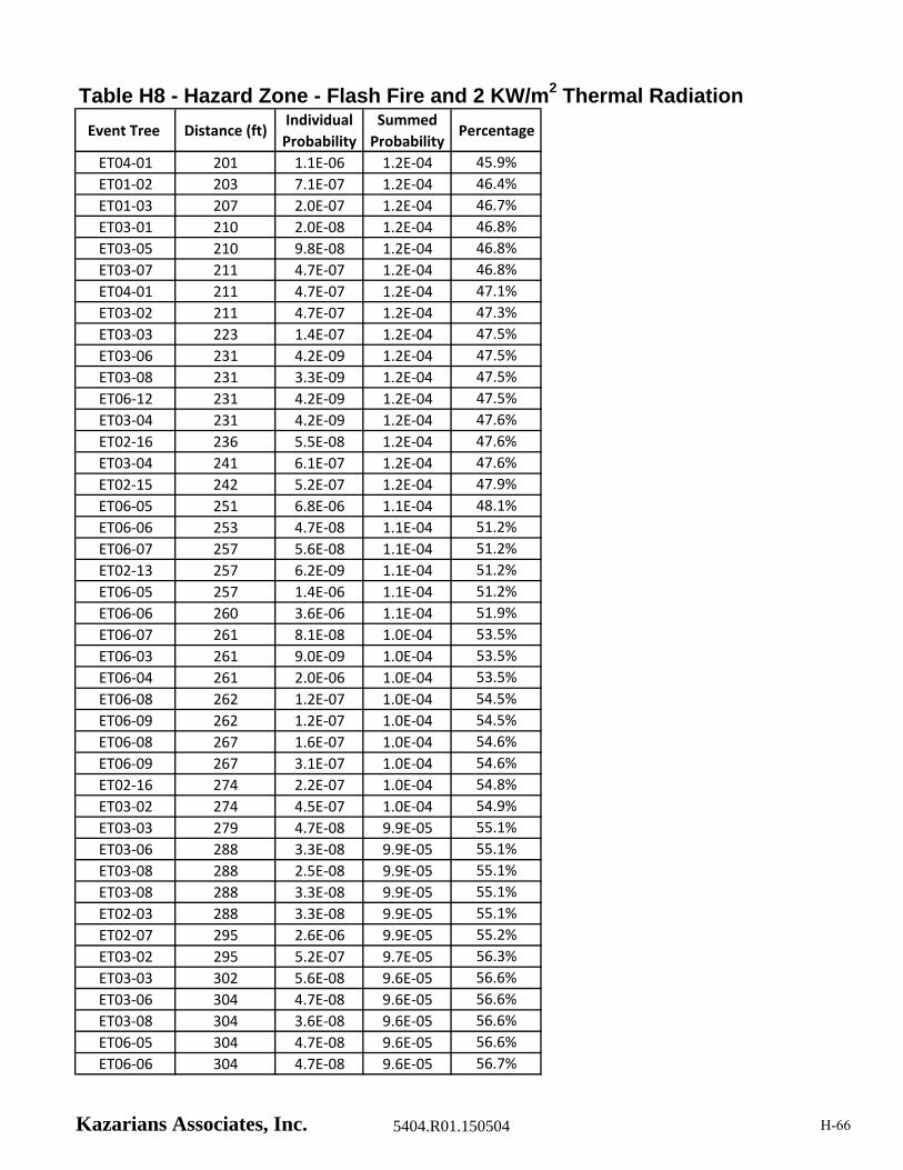
Table H8 - Hazard Zone - Flash Fire and 2 KW/m2 Thermal Radiation
Event Tree Distance (ft)Individual
Probability
Summed
ProbabilityPercentage
ET04‐01 201 1.1E‐06 1.2E‐04 45.9%
ET01‐02 203 7.1E‐07 1.2E‐04 46.4%
ET01‐03 207 2.0E‐07 1.2E‐04 46.7%
ET03‐01 210 2.0E‐08 1.2E‐04 46.8%
ET03‐05 210 9.8E‐08 1.2E‐04 46.8%
ET03‐07 211 4.7E‐07 1.2E‐04 46.8%
ET04‐01 211 4.7E‐07 1.2E‐04 47.1%
ET03‐02 211 4.7E‐07 1.2E‐04 47.3%
ET03‐03 223 1.4E‐07 1.2E‐04 47.5%
ET03‐06 231 4.2E‐09 1.2E‐04 47.5%
ET03‐08 231 3.3E‐09 1.2E‐04 47.5%
ET06‐12 231 4.2E‐09 1.2E‐04 47.5%
ET03‐04 231 4.2E‐09 1.2E‐04 47.6%
ET02‐16 236 5.5E‐08 1.2E‐04 47.6%
ET03‐04 241 6.1E‐07 1.2E‐04 47.6%
ET02‐15 242 5.2E‐07 1.2E‐04 47.9%
ET06‐05 251 6.8E‐06 1.1E‐04 48.1%
ET06‐06 253 4.7E‐08 1.1E‐04 51.2%
ET06‐07 257 5.6E‐08 1.1E‐04 51.2%
ET02‐13 257 6.2E‐09 1.1E‐04 51.2%
ET06‐05 257 1.4E‐06 1.1E‐04 51.2%
ET06‐06 260 3.6E‐06 1.1E‐04 51.9%
ET06‐07 261 8.1E‐08 1.0E‐04 53.5%
ET06‐03 261 9.0E‐09 1.0E‐04 53.5%
ET06‐04 261 2.0E‐06 1.0E‐04 53.5%
ET06‐08 262 1.2E‐07 1.0E‐04 54.5%
ET06‐09 262 1.2E‐07 1.0E‐04 54.5%
ET06‐08 267 1.6E‐07 1.0E‐04 54.6%
ET06‐09 267 3.1E‐07 1.0E‐04 54.6%
ET02‐16 274 2.2E‐07 1.0E‐04 54.8%
ET03‐02 274 4.5E‐07 1.0E‐04 54.9%
ET03‐03 279 4.7E‐08 9.9E‐05 55.1%
ET03‐06 288 3.3E‐08 9.9E‐05 55.1%
ET03‐08 288 2.5E‐08 9.9E‐05 55.1%
ET03‐08 288 3.3E‐08 9.9E‐05 55.1%
ET02‐03 288 3.3E‐08 9.9E‐05 55.1%
ET02‐07 295 2.6E‐06 9.9E‐05 55.2%
ET03‐02 295 5.2E‐07 9.7E‐05 56.3%
ET03‐03 302 5.6E‐08 9.6E‐05 56.6%
ET03‐06 304 4.7E‐08 9.6E‐05 56.6%
ET03‐08 304 3.6E‐08 9.6E‐05 56.6%
ET06‐05 304 4.7E‐08 9.6E‐05 56.6%
ET06‐06 304 4.7E‐08 9.6E‐05 56.7%
Kazarians Associates, Inc. 5404.R01.150504 H-66

Table H8 - Hazard Zone - Flash Fire and 2 KW/m2 Thermal Radiation
Event Tree Distance (ft)Individual
Probability
Summed
ProbabilityPercentage
ET02‐07 313 6.3E‐07 9.6E‐05 56.7%
ET04‐02 340 2.0E‐09 9.5E‐05 57.0%
ET02‐12 343 2.6E‐06 9.5E‐05 57.0%
ET02‐02 348 3.3E‐09 9.3E‐05 58.2%
ET02‐02 359 2.5E‐08 9.3E‐05 58.2%
ET02‐14 360 3.6E‐07 9.3E‐05 58.2%
ET04‐01 365 1.8E‐06 9.2E‐05 58.3%
ET04‐01 372 2.3E‐07 9.0E‐05 59.1%
ET02‐03 372 4.7E‐08 9.0E‐05 59.3%
ET02‐02 378 3.6E‐08 9.0E‐05 59.3%
ET02‐12 403 2.3E‐07 9.0E‐05 59.3%
ET04‐02 407 1.6E‐08 9.0E‐05 59.4%
ET04‐01 412 1.6E‐07 9.0E‐05 59.4%
ET02‐04 416 4.7E‐07 9.0E‐05 59.5%
ET02‐05 416 4.7E‐08 8.9E‐05 59.7%
ET02‐06 416 6.1E‐08 8.9E‐05 59.7%
ET02‐08 416 4.7E‐08 8.9E‐05 59.7%
ET02‐09 416 4.7E‐08 8.9E‐05 59.8%
ET02‐10 416 6.1E‐08 8.9E‐05 59.8%
ET03‐02 423 6.1E‐08 8.9E‐05 59.8%
ET03‐03 423 4.7E‐08 8.9E‐05 59.8%
ET03‐06 423 6.1E‐08 8.9E‐05 59.9%
ET03‐08 423 6.1E‐08 8.9E‐05 59.9%
ET04‐02 436 2.2E‐08 8.9E‐05 59.9%
ET02‐04 446 5.2E‐06 8.9E‐05 59.9%
ET02‐05 446 5.2E‐07 8.3E‐05 62.3%
ET02‐06 446 6.8E‐07 8.3E‐05 62.5%
ET02‐08 446 5.2E‐07 8.2E‐05 62.8%
ET02‐09 446 5.2E‐07 8.2E‐05 63.1%
ET02‐10 446 6.8E‐07 8.1E‐05 63.3%
ET04‐02 446 2.0E‐07 8.0E‐05 63.6%
ET03‐02 447 6.8E‐07 8.0E‐05 63.7%
ET03‐03 447 5.2E‐07 8.0E‐05 64.0%
ET03‐06 447 6.8E‐07 7.9E‐05 64.3%
ET03‐08 447 6.8E‐07 7.8E‐05 64.6%
ET04‐02 490 1.8E‐08 7.8E‐05 64.9%
ET06‐03 508 1.3E‐06 7.8E‐05 64.9%
ET06‐04 508 1.3E‐06 7.6E‐05 65.5%
ET06‐05 544 1.9E‐06 7.5E‐05 66.1%
ET06‐06 544 2.2E‐07 7.3E‐05 67.0%
ET06‐07 544 4.8E‐05 7.3E‐05 67.1%
ET06‐11 595 9.0E‐09 2.4E‐05 88.9%
ET02‐15 617 3.6E‐07 2.4E‐05 88.9%
Kazarians Associates, Inc. 5404.R01.150504 H-67
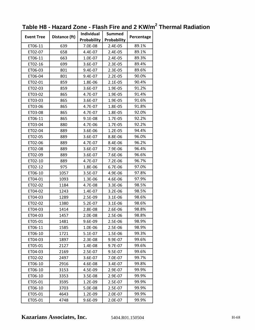
Table H8 - Hazard Zone - Flash Fire and 2 KW/m2 Thermal Radiation
Event Tree Distance (ft)Individual
Probability
Summed
ProbabilityPercentage
ET06‐11 639 7.0E‐08 2.4E‐05 89.1%
ET02‐07 658 4.4E‐07 2.4E‐05 89.1%
ET06‐11 663 1.0E‐07 2.4E‐05 89.3%
ET02‐16 699 3.6E‐07 2.3E‐05 89.4%
ET06‐03 801 9.4E‐07 2.3E‐05 89.6%
ET06‐04 801 9.4E‐07 2.2E‐05 90.0%
ET02‐01 859 1.8E‐06 2.1E‐05 90.4%
ET02‐03 859 3.6E‐07 1.9E‐05 91.2%
ET03‐02 865 4.7E‐07 1.9E‐05 91.4%
ET03‐03 865 3.6E‐07 1.9E‐05 91.6%
ET03‐06 865 4.7E‐07 1.8E‐05 91.8%
ET03‐08 865 4.7E‐07 1.8E‐05 92.0%
ET06‐11 865 9.1E‐08 1.7E‐05 92.2%
ET03‐04 880 4.7E‐06 1.7E‐05 92.2%
ET02‐04 889 3.6E‐06 1.2E‐05 94.4%
ET02‐05 889 3.6E‐07 8.8E‐06 96.0%
ET02‐06 889 4.7E‐07 8.4E‐06 96.2%
ET02‐08 889 3.6E‐07 7.9E‐06 96.4%
ET02‐09 889 3.6E‐07 7.6E‐06 96.6%
ET02‐10 889 4.7E‐07 7.2E‐06 96.7%
ET02‐12 975 1.8E‐06 6.7E‐06 97.0%
ET06‐10 1057 3.5E‐07 4.9E‐06 97.8%
ET04‐01 1093 1.3E‐06 4.6E‐06 97.9%
ET02‐02 1184 4.7E‐08 3.3E‐06 98.5%
ET04‐02 1243 1.4E‐07 3.2E‐06 98.5%
ET04‐03 1289 2.5E‐09 3.1E‐06 98.6%
ET02‐02 1380 5.2E‐07 3.1E‐06 98.6%
ET04‐03 1414 2.8E‐08 2.6E‐06 98.8%
ET04‐03 1457 2.0E‐08 2.5E‐06 98.8%
ET05‐01 1481 9.6E‐09 2.5E‐06 98.9%
ET06‐11 1585 1.0E‐06 2.5E‐06 98.9%
ET06‐10 1721 5.1E‐07 1.5E‐06 99.3%
ET04‐03 1897 2.3E‐08 9.9E‐07 99.6%
ET05‐01 2127 1.4E‐08 9.7E‐07 99.6%
ET04‐03 2169 2.5E‐07 9.5E‐07 99.6%
ET02‐02 2497 3.6E‐07 7.0E‐07 99.7%
ET06‐10 2916 4.6E‐08 3.4E‐07 99.8%
ET06‐10 3153 4.5E‐09 2.9E‐07 99.9%
ET06‐10 3353 3.5E‐08 2.9E‐07 99.9%
ET05‐01 3595 1.2E‐09 2.5E‐07 99.9%
ET06‐10 3703 5.0E‐08 2.5E‐07 99.9%
ET05‐01 4643 1.2E‐09 2.0E‐07 99.9%
ET05‐01 4748 9.6E‐09 2.0E‐07 99.9%
Kazarians Associates, Inc. 5404.R01.150504 H-68

Table H8 - Hazard Zone - Flash Fire and 2 KW/m2 Thermal Radiation
Event Tree Distance (ft)Individual
Probability
Summed
ProbabilityPercentage
ET05‐01 5307 1.4E‐08 1.9E‐07 99.9%
ET04‐03 5569 1.8E‐07 1.8E‐07 99.9%
Kazarians Associates, Inc. 5404.R01.150504 H-69
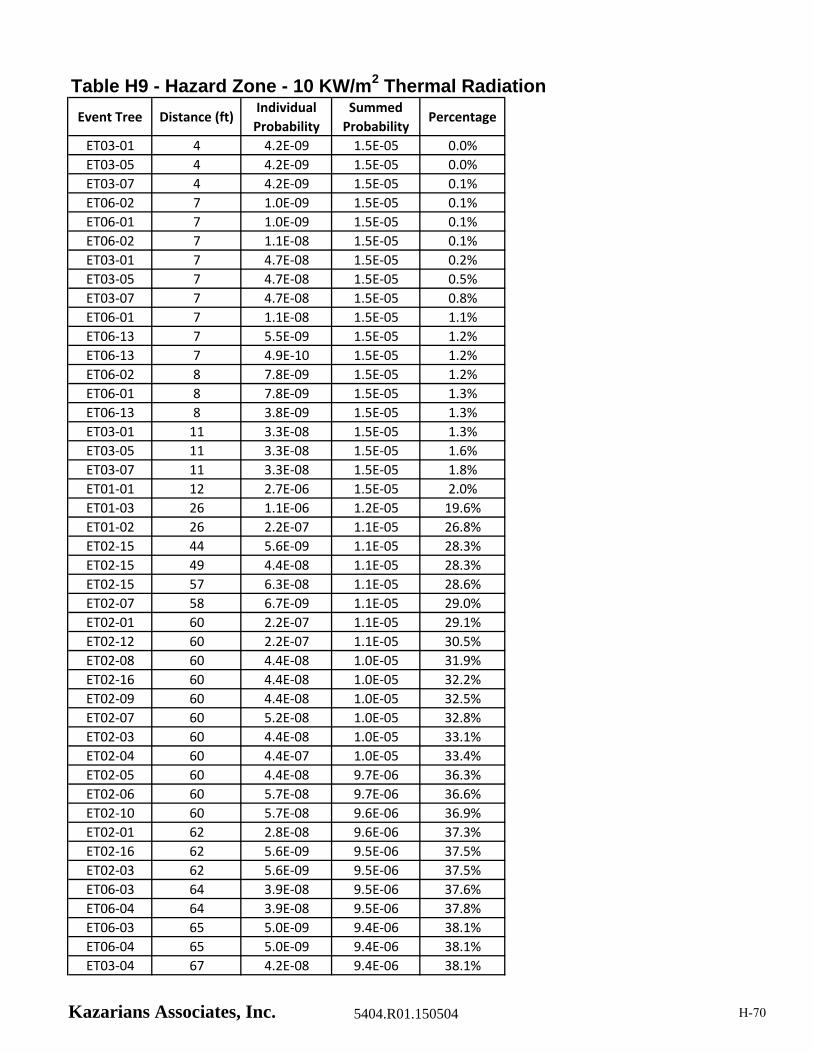
Table H9 - Hazard Zone - 10 KW/m2 Thermal Radiation
Event Tree Distance (ft)Individual
Probability
Summed
ProbabilityPercentage
ET03‐01 4 4.2E‐09 1.5E‐05 0.0%
ET03‐05 4 4.2E‐09 1.5E‐05 0.0%
ET03‐07 4 4.2E‐09 1.5E‐05 0.1%
ET06‐02 7 1.0E‐09 1.5E‐05 0.1%
ET06‐01 7 1.0E‐09 1.5E‐05 0.1%
ET06‐02 7 1.1E‐08 1.5E‐05 0.1%
ET03‐01 7 4.7E‐08 1.5E‐05 0.2%
ET03‐05 7 4.7E‐08 1.5E‐05 0.5%
ET03‐07 7 4.7E‐08 1.5E‐05 0.8%
ET06‐01 7 1.1E‐08 1.5E‐05 1.1%
ET06‐13 7 5.5E‐09 1.5E‐05 1.2%
ET06‐13 7 4.9E‐10 1.5E‐05 1.2%
ET06‐02 8 7.8E‐09 1.5E‐05 1.2%
ET06‐01 8 7.8E‐09 1.5E‐05 1.3%
ET06‐13 8 3.8E‐09 1.5E‐05 1.3%
ET03‐01 11 3.3E‐08 1.5E‐05 1.3%
ET03‐05 11 3.3E‐08 1.5E‐05 1.6%
ET03‐07 11 3.3E‐08 1.5E‐05 1.8%
ET01‐01 12 2.7E‐06 1.5E‐05 2.0%
ET01‐03 26 1.1E‐06 1.2E‐05 19.6%
ET01‐02 26 2.2E‐07 1.1E‐05 26.8%
ET02‐15 44 5.6E‐09 1.1E‐05 28.3%
ET02‐15 49 4.4E‐08 1.1E‐05 28.3%
ET02‐15 57 6.3E‐08 1.1E‐05 28.6%
ET02‐07 58 6.7E‐09 1.1E‐05 29.0%
ET02‐01 60 2.2E‐07 1.1E‐05 29.1%
ET02‐12 60 2.2E‐07 1.1E‐05 30.5%
ET02‐08 60 4.4E‐08 1.0E‐05 31.9%
ET02‐16 60 4.4E‐08 1.0E‐05 32.2%
ET02‐09 60 4.4E‐08 1.0E‐05 32.5%
ET02‐07 60 5.2E‐08 1.0E‐05 32.8%
ET02‐03 60 4.4E‐08 1.0E‐05 33.1%
ET02‐04 60 4.4E‐07 1.0E‐05 33.4%
ET02‐05 60 4.4E‐08 9.7E‐06 36.3%
ET02‐06 60 5.7E‐08 9.7E‐06 36.6%
ET02‐10 60 5.7E‐08 9.6E‐06 36.9%
ET02‐01 62 2.8E‐08 9.6E‐06 37.3%
ET02‐16 62 5.6E‐09 9.5E‐06 37.5%
ET02‐03 62 5.6E‐09 9.5E‐06 37.5%
ET06‐03 64 3.9E‐08 9.5E‐06 37.6%
ET06‐04 64 3.9E‐08 9.5E‐06 37.8%
ET06‐03 65 5.0E‐09 9.4E‐06 38.1%
ET06‐04 65 5.0E‐09 9.4E‐06 38.1%
ET03‐04 67 4.2E‐08 9.4E‐06 38.1%
Kazarians Associates, Inc. 5404.R01.150504 H-70
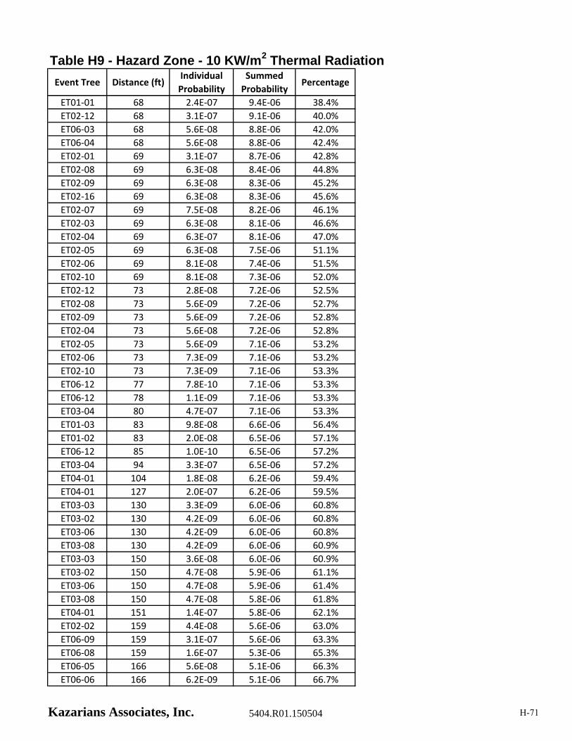
Table H9 - Hazard Zone - 10 KW/m2 Thermal Radiation
Event Tree Distance (ft)Individual
Probability
Summed
ProbabilityPercentage
ET01‐01 68 2.4E‐07 9.4E‐06 38.4%
ET02‐12 68 3.1E‐07 9.1E‐06 40.0%
ET06‐03 68 5.6E‐08 8.8E‐06 42.0%
ET06‐04 68 5.6E‐08 8.8E‐06 42.4%
ET02‐01 69 3.1E‐07 8.7E‐06 42.8%
ET02‐08 69 6.3E‐08 8.4E‐06 44.8%
ET02‐09 69 6.3E‐08 8.3E‐06 45.2%
ET02‐16 69 6.3E‐08 8.3E‐06 45.6%
ET02‐07 69 7.5E‐08 8.2E‐06 46.1%
ET02‐03 69 6.3E‐08 8.1E‐06 46.6%
ET02‐04 69 6.3E‐07 8.1E‐06 47.0%
ET02‐05 69 6.3E‐08 7.5E‐06 51.1%
ET02‐06 69 8.1E‐08 7.4E‐06 51.5%
ET02‐10 69 8.1E‐08 7.3E‐06 52.0%
ET02‐12 73 2.8E‐08 7.2E‐06 52.5%
ET02‐08 73 5.6E‐09 7.2E‐06 52.7%
ET02‐09 73 5.6E‐09 7.2E‐06 52.8%
ET02‐04 73 5.6E‐08 7.2E‐06 52.8%
ET02‐05 73 5.6E‐09 7.1E‐06 53.2%
ET02‐06 73 7.3E‐09 7.1E‐06 53.2%
ET02‐10 73 7.3E‐09 7.1E‐06 53.3%
ET06‐12 77 7.8E‐10 7.1E‐06 53.3%
ET06‐12 78 1.1E‐09 7.1E‐06 53.3%
ET03‐04 80 4.7E‐07 7.1E‐06 53.3%
ET01‐03 83 9.8E‐08 6.6E‐06 56.4%
ET01‐02 83 2.0E‐08 6.5E‐06 57.1%
ET06‐12 85 1.0E‐10 6.5E‐06 57.2%
ET03‐04 94 3.3E‐07 6.5E‐06 57.2%
ET04‐01 104 1.8E‐08 6.2E‐06 59.4%
ET04‐01 127 2.0E‐07 6.2E‐06 59.5%
ET03‐03 130 3.3E‐09 6.0E‐06 60.8%
ET03‐02 130 4.2E‐09 6.0E‐06 60.8%
ET03‐06 130 4.2E‐09 6.0E‐06 60.8%
ET03‐08 130 4.2E‐09 6.0E‐06 60.9%
ET03‐03 150 3.6E‐08 6.0E‐06 60.9%
ET03‐02 150 4.7E‐08 5.9E‐06 61.1%
ET03‐06 150 4.7E‐08 5.9E‐06 61.4%
ET03‐08 150 4.7E‐08 5.8E‐06 61.8%
ET04‐01 151 1.4E‐07 5.8E‐06 62.1%
ET02‐02 159 4.4E‐08 5.6E‐06 63.0%
ET06‐09 159 3.1E‐07 5.6E‐06 63.3%
ET06‐08 159 1.6E‐07 5.3E‐06 65.3%
ET06‐05 166 5.6E‐08 5.1E‐06 66.3%
ET06‐06 166 6.2E‐09 5.1E‐06 66.7%
Kazarians Associates, Inc. 5404.R01.150504 H-71
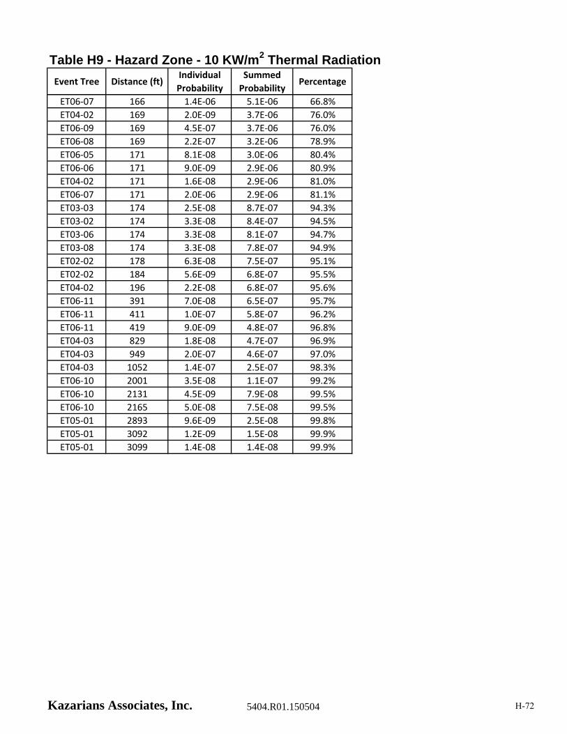
Table H9 - Hazard Zone - 10 KW/m2 Thermal Radiation
Event Tree Distance (ft)Individual
Probability
Summed
ProbabilityPercentage
ET06‐07 166 1.4E‐06 5.1E‐06 66.8%
ET04‐02 169 2.0E‐09 3.7E‐06 76.0%
ET06‐09 169 4.5E‐07 3.7E‐06 76.0%
ET06‐08 169 2.2E‐07 3.2E‐06 78.9%
ET06‐05 171 8.1E‐08 3.0E‐06 80.4%
ET06‐06 171 9.0E‐09 2.9E‐06 80.9%
ET04‐02 171 1.6E‐08 2.9E‐06 81.0%
ET06‐07 171 2.0E‐06 2.9E‐06 81.1%
ET03‐03 174 2.5E‐08 8.7E‐07 94.3%
ET03‐02 174 3.3E‐08 8.4E‐07 94.5%
ET03‐06 174 3.3E‐08 8.1E‐07 94.7%
ET03‐08 174 3.3E‐08 7.8E‐07 94.9%
ET02‐02 178 6.3E‐08 7.5E‐07 95.1%
ET02‐02 184 5.6E‐09 6.8E‐07 95.5%
ET04‐02 196 2.2E‐08 6.8E‐07 95.6%
ET06‐11 391 7.0E‐08 6.5E‐07 95.7%
ET06‐11 411 1.0E‐07 5.8E‐07 96.2%
ET06‐11 419 9.0E‐09 4.8E‐07 96.8%
ET04‐03 829 1.8E‐08 4.7E‐07 96.9%
ET04‐03 949 2.0E‐07 4.6E‐07 97.0%
ET04‐03 1052 1.4E‐07 2.5E‐07 98.3%
ET06‐10 2001 3.5E‐08 1.1E‐07 99.2%
ET06‐10 2131 4.5E‐09 7.9E‐08 99.5%
ET06‐10 2165 5.0E‐08 7.5E‐08 99.5%
ET05‐01 2893 9.6E‐09 2.5E‐08 99.8%
ET05‐01 3092 1.2E‐09 1.5E‐08 99.9%
ET05‐01 3099 1.4E‐08 1.4E‐08 99.9%
Kazarians Associates, Inc. 5404.R01.150504 H-72