jyoti cnc project report
DESCRIPTION
this is the project report for jyoti cnc techanical tranning for mechanical students with brief details.TRANSCRIPT
REPORT ON INDURISTAL TRANNING HELD AT
JYOTI CNC AUTOMATION PVT. LTD.RAJKOT.

INDEX
I. PrefaceII. Acknowledgment
III. declaration
1. Introduction2. General information
2.11 Portfolio2.12 Brief History & Development2.13 Size of Unit2.14 Organizational Structure
3. Foundry4. Machining5. Assembly

PREFACE
Practical training is also very important aspect in technical course. There is so many times vast differences between theoretical knowledge and actual practical implication.
Thus practical training helps individuals of know he actual uses and impaction of what he has gained from theoretical knowledge. The theoretical knowledge and classroom discussion is not enough for a technical student now, for the knowledge of practical viewpoints, problems, opportunities and situation of industrial units practical studies is necessary.
So as the students of 6 th sem. B.Tech We also a get a valuable opportunities to learn the practically of the theories, which learn.
We have tried to collect all the necessary information and had tried to prepare this report
with the best of our knowledge and ability.

ACKNOWLEDGMENT
The visit/training industry is a part of our study as implied by Rajasthan Technical University.
We are heartily grateful to all the executives of JYOTI CNC AUTOMATION PVT. LTD. for developing their valuable time and providing us necessary information regarding company and its management.
Our special thanks to Mr. VINCENT DABHI who have made a great effort for making the training program smooth and easy going.
We must also convey our special thanks to the sir and the director for giving us this wider horizon of sphere of knowledge and finding time for reading and commenting a portion of the manuscript.
THANK YOU.

DICLARATION
We the undersigned, DADHANIA MANTHAN, the students of S.S. COLLEGE OF ENGINEERING hereby declare that this report is our own work carried out under supervision and guidance of managers.
This report has not submitted to any university or institute for examination by any one.
DATE:-……………………….PLACE:-……………………..
Sign of student,
………………………… (DADHANIA MANTHAN)
INTRODUCTION

Jyoti is the brainchild of legendary Mr. P.G. Jadeja & Mr. S.L. Jadeja. Establish in 1989. Driven by the vision to build the company “A temple of technology “through teamwork, the company has grown manifold from manufacturing gear boxes for machines. Later on jyoti has rightly identified sift from conventional machines to highly sophisticated cnc machines in the presence of manufactures.
Jyoti was the first company to manufacturing cnc machines in the Gujarat. It was not an end. There are many first attached with jyoti since then jyoti driven by technology and innovation keeps including new fire power in its arsenal by introducing machines like CNC turning center, Vertical Machining Centers, Oval turning center i- Sect and first Indian machines like vmc 40/70 Linear with innovative linear technology.
After the opening of the Indian economy, there were great challenges present for Indian companies but jyoti converted all challenges to the excellent opportunities. Jyoti has even decided to compete at the global level and taken concrete steps by exporting cnc machines. It has also established various distribution continents around the globe.
Jyoti is passing through the trajectory of rapid growth by achieving over 100% growth rate since its inception. Export penetration and inclination has helped jyoti to establish the goodwill among the foreign buyers and distributors.
Company’s expanding footprints ensures its global presence with exports operations in countries like Italy, Russia, Argentina, Brazil and rest of South America, Tanzania and some African countries, Middle East and other Asian countries like Malaysia .

GENERALINFORMATION

1. Portfolio
Name of the company : Jyoti cnc Automation Pvt. Ltd.
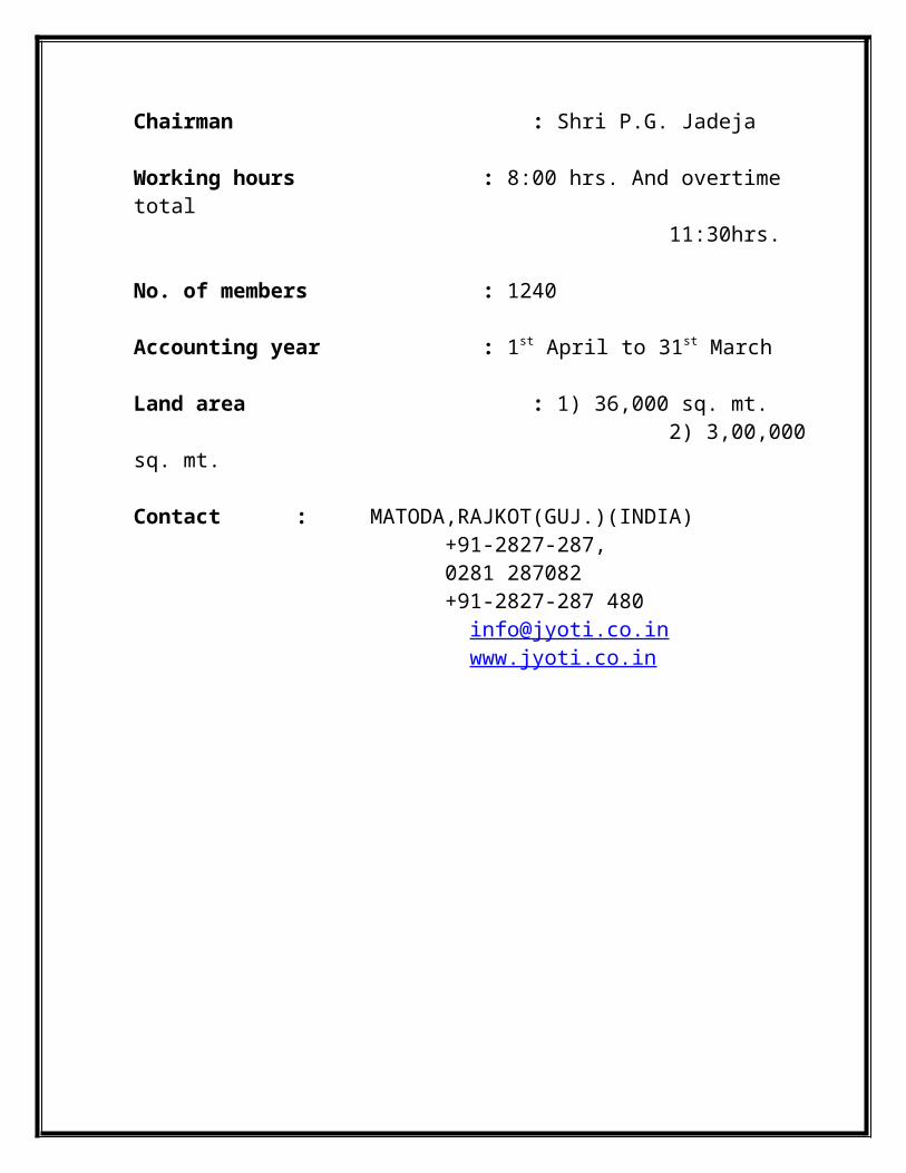
Chairman : Shri P.G. Jadeja
Working hours : 8:00 hrs. And overtime total 11:30hrs.
No. of members : 1240
Accounting year : 1st April to 31st March
Land area : 1) 36,000 sq. mt. 2) 3,00,000 sq. mt.
Contact : MATODA,RAJKOT(GUJ.)(INDIA) +91-2827-287, 0281 287082 +91-2827-287 480 [email protected] www.jyoti.co.in
2.BRIEF HISTORY
& DEVELOPMENT
JYOTI CNC Pvt. Ltd. is promoted by an industrial entrepreneurs group having a track record of achievement the character of group by its products and services, a priceless performance asset, achieved its success not by an accident, but by sheet hard work declaration and foresight, by the people who work with it.
JYOTI CNC Pvt. Ltd. established as a small scale industry at the Gondal road in 1988. The chair man of the company named P.G. JADEJA started the business with his two brothers of rs. 30,000 by taking loan.
YEAR MILESTONE1988 Jyoti established1989 Introduced trouble free gear boxes for small lathes1992 Designed all geared lathes1994 Designed several special purpose machines which
helped textile industry to bring substantial price reduction in component manufacturing
1996 Designed twine spindle (chucker) type machine. The first in Rajkot
1997 Designed and manufactured first cnc turning center in Gujarat
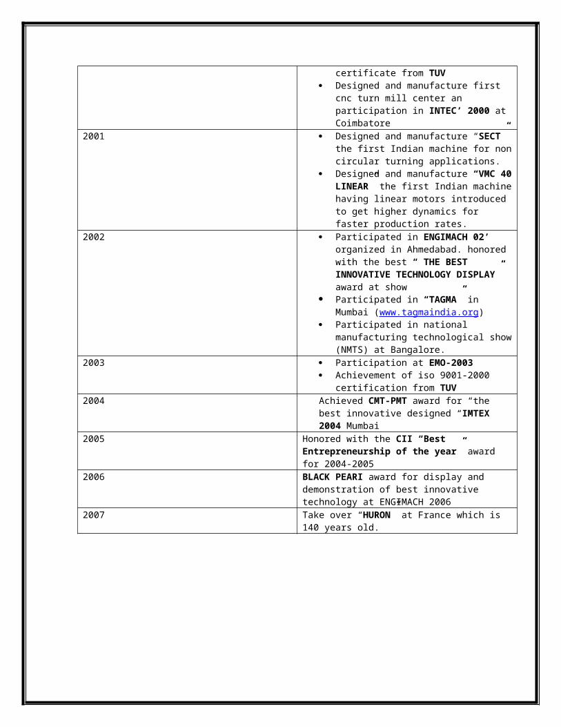
2000 Achieved the international standard for quality management system an iso 9001-1994 certificate from TUV
Designed and manufacture first cnc turn mill center an participation in INTEC’ 2000 at Coimbatore
2001 Designed and manufacture “SECT” the first Indian machine for non circular turning applications.
Designed and manufacture “VMC 40 LINEAR” the first Indian machine having linear motors introduced to get higher dynamics for faster production rates.
2002 Participated in ENGIMACH 02’ organized in Ahmedabad. honored with the best “ THE BEST INNOVATIVE TECHNOLOGY DISPLAY” award at show
Participated in “TAGMA” in Mumbai (www.tagmaindia.org)
Participated in national manufacturing technological show (NMTS) at Bangalore.

2003 Participation at EMO-2003 Achievement of iso 9001-2000 certification
from TUV2004 Achieved CMT-PMT award for “the best
innovative designed “IMTEX 2004 Mumbai2005 Honored with the CII “Best Entrepreneurship of the
year” award for 2004-20052006 BLACK PEARI award for display and demonstration
of best innovative technology at ENGIMACH 20062007 Take over “HURON” at France which is 140 years old.
3. SIZE OF UNIT
On the basis of size, nature, capital investment and production capacity industries can be divided into three major groups,
Small scale industry Medium scale industry Large scale industry
Jyoti pvt. Ltd. can be placed under the large scale group as the capital invested in the machinery.
4. Organizational Structure
The superior-subordinate relationship is defined by organizational structure. Which are formal documents, which indicate the chain of command and the title have been assigned to the managers and the other personnel? These structures are somewhat like “ROAD MAPS” as they guide to official relationship. Organizational structure indicates the people’s location or the position in the hierarchy and their relationship within the formal organization. They aid in determining which of the basic type of organizational authority structure a particular enterprise has adopted.
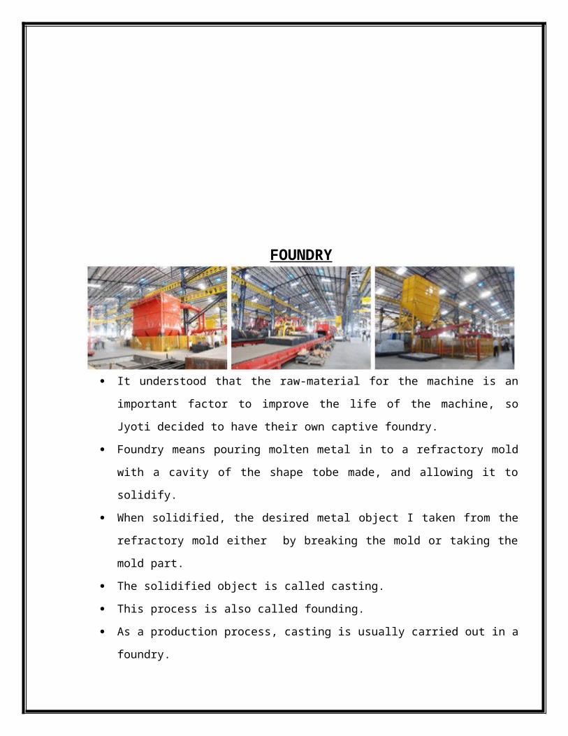
FOUNDRY
It understood that the raw-material for the machine is an important factor to improve the
life of the machine, so Jyoti decided to have their own captive foundry.
Foundry means pouring molten metal in to a refractory mold with a cavity of the shape
tobe made, and allowing it to solidify.
When solidified, the desired metal object I taken from the refractory mold either by
breaking the mold or taking the mold part.
The solidified object is called casting.
This process is also called founding.
As a production process, casting is usually carried out in a foundry.
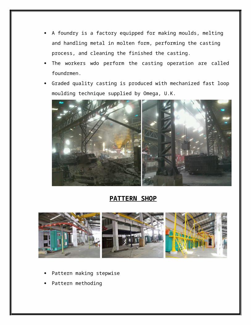
A foundry is a factory equipped for making moulds, melting and handling metal in
molten form, performing the casting process, and cleaning the finished the casting.
The workers wdo perform the casting operation are called foundrmen.
Graded quality casting is produced with mechanized fast loop moulding technique
supplied by Omega, U.K.
PATTERN SHOP
Pattern making stepwise
Pattern methoding
Pattern designing
Core designing
Pattern raw material designing
Core raw material designing
Pattern drawing preparation
Core raw material preparation
Inspection of raw material
Machining of pattern raw material
Machining of core raw material
Pattern screwing and assembling
Core screwing and assembling
Final inspection
Pattern mounting and methoding
Final inspection
Pattern mounting and methoding
Sand preparation
Coastal sand is taken in use for preparing the mould. Some important properties of molding sand for obtaining good mould and casting are:-
Strength Permeability Thermal stability Collapsibility Reusability
Constituents of moulding sand:-
Silica sand Binder Additives Water
Silica sand:-
Silica sand (SiO2) contains water for a long time and is suitable for a wide working range.
It helps to patching and finishing operation of the mould. It is very cheap as compared to other sand . Mostly used for cast iron and non ferrous metal casting
Binders:-
The purpose of adding a binder to the moulding sand is to impart it sufficient strength and cohesiveness so as to unable it to retain it shape after the mould has been rammed and the pattern withdrawn.
However it produce and adverse effect on the permeability of the sand mould.
Additives:-

Additives are those materials which are added to the moulding sand to improve upon some of existing properties of the impart certain new properties to it
Commonly used additives are:-
Coal dust Sea coal Cereals or corn flour Silica flour Wood flour Pitch Dextrin and molasses Fuel oil
Water
The clay contend added to foundry and sand will not give the required strength and bond until a suitable quantity of water is added to it.
This quantity of water varies from 2 to 8 percent according to different requirements.
Mould Classifications:-
Sand moulds Green sand moulds Dry sand moulds Skin sand moulds
Cement sand moulds Sodium silicate Metal moulds

Plaster moulds
Mould Making
First the coastel sand is dried in a sand drier. Sand drier dries the sand by heating at high temperature. Then it is send to the bucket alivator for cooling. The dry sand is lifted and send to the mould mixture. Mould is prepared by adding rasin and catalyst it to it.
Furnace :-
In all the casting processes, the metal must be heated to the molten state to be poured into the mould.
Heating and melting is done in the furnace. Various types of furnace used in the foundry are:-
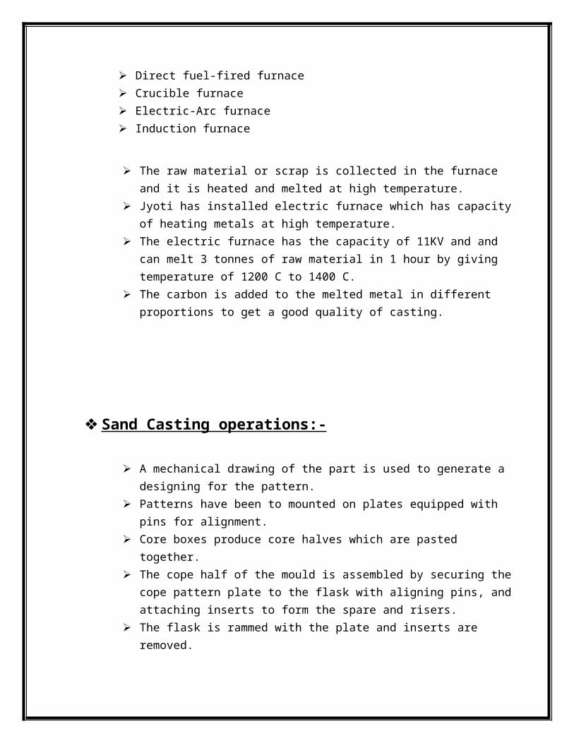
Cupolas Direct fuel-fired furnace Crucible furnace Electric-Arc furnace Induction furnace
The raw material or scrap is collected in the furnace and it is heated and melted at high temperature.
Jyoti has installed electric furnace which has capacity of heating metals at high temperature.
The electric furnace has the capacity of 11KV and and can melt 3 tonnes of raw material in 1 hour by giving temperature of 1200 C to 1400 C.
The carbon is added to the melted metal in different proportions to get a good quality of casting.
Sand Casting operations:-

A mechanical drawing of the part is used to generate a designing for the pattern. Patterns have been to mounted on plates equipped with pins for alignment. Core boxes produce core halves which are pasted together. The cope half of the mould is assembled by securing the cope pattern plate to the
flask with aligning pins, and attaching inserts to form the spare and risers. The flask is rammed with the plate and inserts are removed. The drag half is produced in similar manner, with the pattern inserted. A bottom board is placed below the drag and aligned with pin. The pattern, flask, and bottom are inverted, and the pattern is withdrawn, leaving the
appropriate imprint. The core is set in place within the drag cavity. The mould is closed by placing the cope on the top of the drag and securing the
assembly with the pins. The flask are then subjected to pressure to conteract buoyant forces in the liquid,
which might lift the cope. After the metal solidifies, the casting is removed from the mould. The sprue and rises are cut off and the casting is cleaned.
MACHINING

In Unit-2 , is machining shop.There is various machining process like milling , grinding , threading , turning , boring , slotting , etc. done.
For the various machinig process , various machines used which are listed below ,1. VMC-6402. HMC-5603. DX-1004. DX-1505. DX-2006. DX-2507. DX-3008. DX-3509. TC-0110. TC-0211. TMC-25012. TMC-250A13. TMC-35014. ATM-16015. HMC-56016. Slide way Grinding Machine17. Horizontal Boring Machine
INRODUCTION ABOUT VMC-640:-
Different type maching process which are performed by VMC-640 as boring , milling , threading , feeding , slotting .
VMC-640 is four axis machine X,Y,Z,A . Maximum feed :- 20,000 to 40,0000 . R.P.M. :- 10,000 may be for special purpose . Automatic Tool Changer (ATC) :- 20 tools max. Motors used :- Three motors for its X,Y,Z axes . Bed & Spindle Rotary Table :- Its move about 360 degree For VMC , vertical axis is consider as a Z axis. In VMC X,Y axis moves and Z axis can be up & down , not moved. In Z axis spindle rotate in clockwise & anticlockwise direction. TANK:- Coolant tank, slideway lubrication tank, clean coolen tank (optional).
For auto operation VMC used Siemens system which is based on computer rised programme.
Various functions of the switches which is used in programming machining process enlisted as below,
1. RESET: - Machine reset by using this switch.2. SINGLE BLOCK:- By using this switch, only one block is processed or on operation.3. CYCLE STOP / START: - It is used to stop or start the cycle. Cycle can be defined on the
based of the operation which is completed.4. AUTO PRO: - Which is defined programme for particular job that saved in system.5. M01:- It is the code of the programme. In the programme wherever, M01 is used that means
programme or machining process is stopped after that step.6. DRY: - It is used to inform all the data of the job.7. MDA: - It is used to add manually programme.8. JOG: - When the cycle is stopped and after that the axes of the job required to move , then
without JOG axes cannot move. First of all , it gives JOG command then it can be possible the movement of the axes.
9. REFRRENCE POINT:- It is used for the reference.10. VAR: - There is the four vertical key as VAR, 1 ,10 , 100 . 1:- it is used to move job 1
micron in any direction. Function of 10 & 100 keys is also same as key 1.11. M/C on12. ARM JOG13. SPEED SWITCH: - By using switch , the speed of machine operated manually.It is usually
100 %.14. FEED SWITCH: - It is used for feed rate.15. EMERGENCY SWITCH: - It is used to stop the machine in emergency condition.
All the switches that mentioned as above which is used in Siemens programming system.

TOOL USED IN VMC:- Ø 63 mm cutter Ø 25 mm cutter Ø 13 mm drill Ø 10 mm mill Ø 6.8 mm drill Ø 6.8 mm long drill Ø 8.6 mm drill Ø 4 mm drill Ø 4.2 mm drill 16 mm insert cutter Ø 8 mm mill 16 mm champer cutter Ø 8,10,5 mm lap (thread) 54 mm degree cutter 104 mm boring bar 80 mm finish cutter Tool holder in which insert is mounted Material used in insert cutter is carbide . Properties of this material is pure brittle.
INTRODUCTION TO THE HMC-560
in HMC-560,there is a four axes X,Y,Z and B. axis B is considered as a movement of pallet two palletes used in it. HMC used for big components. In HMC two palletes are used for save the time to change the job. Its has accuracy about 10 micron Tools heavy and capacity of the tools is 40 Magazine is provided in back side of the machine and also saprated from working
area or chamber. Used boring bar in two finish boring bar and two rough boring bar. Tools of the HMC-560 is same as the tools of VMC-540
DX - 250, 200, 350
By this machine only turning may be possible. There are two axes used as X and Z. Z axis is consider as a spindle axis and it is horizontal axis. In this machine turret has a capacity to carrying 8 tools. Coolant system of the CNC machine. There is the different maintained coolant nozzle and injector used for that. Coolant system is also joined with the turret and also mountained on the machine
body or top of the job which is controlleble by the programme. If any m.s. job has been rejected after the various machining processes
then for further use of it can be coated by Crome which is the coating material. After the coating all the machining process has been done.
General formula to find out rpm and feed:-
For drilling : for carbide,
rpm=(40¿60)×1000π ×drilldia .
feed=rpm× (0.1¿0.5 ) For HSS :-
rpm=(8¿25)×1000π ×drill dia .
feed=rpm×(0.1¿0.15)
For milling :- for carbide,
rpm=(50¿70)×1000π ×end milling dia.
Type equationhere .
feed=rpm×(0.1¿0.15) For HSS :-
rpm=(15¿30)×1000π ×end mill dia .
For cutter :-number of insert cutter
rpm=(180t o210)×1000π ×cutter dia .
feed=rpm× ¿15)
ASSEMBLY

In assembly workshop there is the all part of the machines assembled by dividing
according to various machining process.
We are in turning side , in which all of the DX series machines developed , like wise
DX 50 , DX 100 , DX 150 , DX 200 , DX 250 , DX 300 , DX 350 .
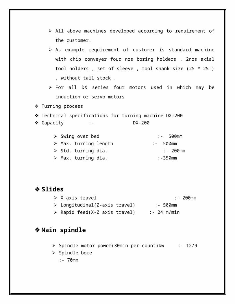
All above machines developed according to requirement of the customer.
As example requirement of customer is standard machine with chip conveyer four nos
boring holders , 2nos axial tool holders , set of sleeve , tool shank size (25 * 25 ) ,
without tail stock .
For all DX series four motors used in which may be induction or servo motors
Turning process
Technical specifications for turning machine DX-200 Capacity :- DX-200
Swing over bed :- 500mm Max. turning length :- 500mm Std. turning dia. :- 200mm Max. turning dia. :-350mm
Slides X-axis travel :- 200mm Longitudinal(Z-axis travel) :- 500mm Rapid feed(X-Z axis travel) :- 24 m/min
Main spindle
Spindle motor power(30min per count)kw :- 12/9

Spindle bore :- 70mm Spindle nose :- A26 Max. bar capacity :-52mm Spindle speed range(rpm) :-50-4000 rpm full power speed range :-750-3250 rpm
Turret (servo) Number of station :- 8 Max. boring bar dia. :- 40 mm Tool size (cross sectional) :- 25*25 mm
Tailstock
Quill dia. :- 85 mm Quill stroke :- 120 mm Thrust (adjustabl) :- 500 kgf(max) Accuracy ( as per VDI/DGQ 3441) Positioning uncertainty (p) mm :- 0.007 mm Repeatability ( ps medium ) :- 0.005 mm
Other
weight (approx) :- 3900 kg dimension (l*w*h)( approx ) :-2690*1635*1485 mm
Controller
the CNC system offered with the DX series machine is the latest system sinomerzk 802dsl digital control system is also available as option
simulataneous 4 axes control 10.4’’ TFT color screen Real time simulation PLC ladder display for diagnostics spindle load meter Background editing 1 MB memory auto referencing oriented spindle stop inch/ matric switchable

online help multiple repetitive cycles thread cutting cycles constant surface speed control rigid tapping pitch error compensation tool nose radius compenstion backlash compenstion direct drawing dimention G-code compatibility RS-232C serial interface port Inbuilt calculator Electronic hand wheel PCMCIA carel slot
Standard features
Ac spindle drive Ac servo digital drive L.M guide ways Hyd. Chucking 8 station bi-directional servo turret Auto and manual coolant system Centraised and programmable lub. System Laser calibrated axis of highly precise Positioning accuracy and repeatability
Productivity improvement option
Chip conveyor (rear or side) Bar feeder Bar puller Programmable tail stoke Part catcher Auto door Automatic tool setting Hyd. Collet chuck Fully tooled up solution to meet Customer needs Live quill ( built in revolving center)
Two speed gear box
DX-200 CNC turning center Overview
In today’s competive market, you need to produce world class products quickly , accurately and with the minimum of the non-productive time
You can find a range of high technology CNC lathes that deliver the fastest throughout you need in DX series manufactured by jyoti. This machines are a result of continuous developments and innovation we have made in the field of machine tool ever since we started manufacturing CNC lathes compiling and considering the customer feedbacks and incorporative our own innovations. DX-200 with its unique feature delivers optimum performance to match demand of various work piece size application.
Rigid structure
The rigid bed and single piece 30 deg slant saddle are made out of high grade cast iron for stability and least distortion enabling heavy cuts and faster production with virtually no vibration it means higher surface finish even on hard materials.
Step up structure concept enables consistent performance because of widely space quid ways even it bigger diameter.
Spindle
main spindle is manufactured in house using world class machiniry and assembled in a dust free controlled temperature environment. Spindle is housed in a cartiidge with 3 super precision angular contaet bearings in the front and angular contact bearing at rear and this arrangment takes care of radius as well as axis loads.
Head Stock

Made out of closed grain FG300 casting and provided with fins for better hear dissipation.
3-Point Leveling System
Due to high rigidity of the base design and 3 point leveling, twisting of bed is
eliminated. This feature in 200 allows machine to be installed or relocated quickly
easily.
Tail Stock
A manually moveable tailstock with hydraulically accreted quill is a standard feature of the machine. Programmable tailstock with hydraulic movement is offered as an option.
High Speed Servo Turret
DX-200 machine is equipped with high speed and high precision bi- directional servo turret with clamping system archived by 3 piece coupling. tool change time in just 0.5 sec.
Automatic Tool Setting
Programmable for confident unmanned running . allows the machine to set accurate tool data and even defact in process tool wear or breakages.
CNC system used in turning process
Siemens 808 DT Siemen 802 DSL Siemens 810 D
Fanus 0i mate TD Fanus 0i TD plus alpha drives
Various turret used in CNC JST 63 JST 80 JST 125 BTP 63 BTP 80 BTP 100 BTP 125 8 stn 12 stn Live tool turret
Tail stock
Prog. Tail stock Pro. Quill Servo T.S. Revolving Centre Live center Collate chuck Customize fixture Others…………. Chip conveyor(Std.) Chip tray Chip conveyor(Scraper type)
Others
Tool eye Work piece measuring system Gearbox Part catcher Bar feeder Auto door Tower light Tool load monitoring Customized color Customized cutting tool
Various Test

Squareness test Coolant trail Geometrical test Laser calibration Ballbar test Spindle vibration Cutting trail Practical test Final inspection Pre dispatched inspection