jedi jedi electric garage door... · before installing jedi, please check the following basic...
TRANSCRIPT

IL n. 321EDIZ. 01/11/2013
JEDI
ELECTROMECHANICAL ACTUATOR FOR SPRING AND COUNTERWEIGHT BALANCED DOORS
GB
www.remotecontrolgates.co.uk
ENGLISH
13
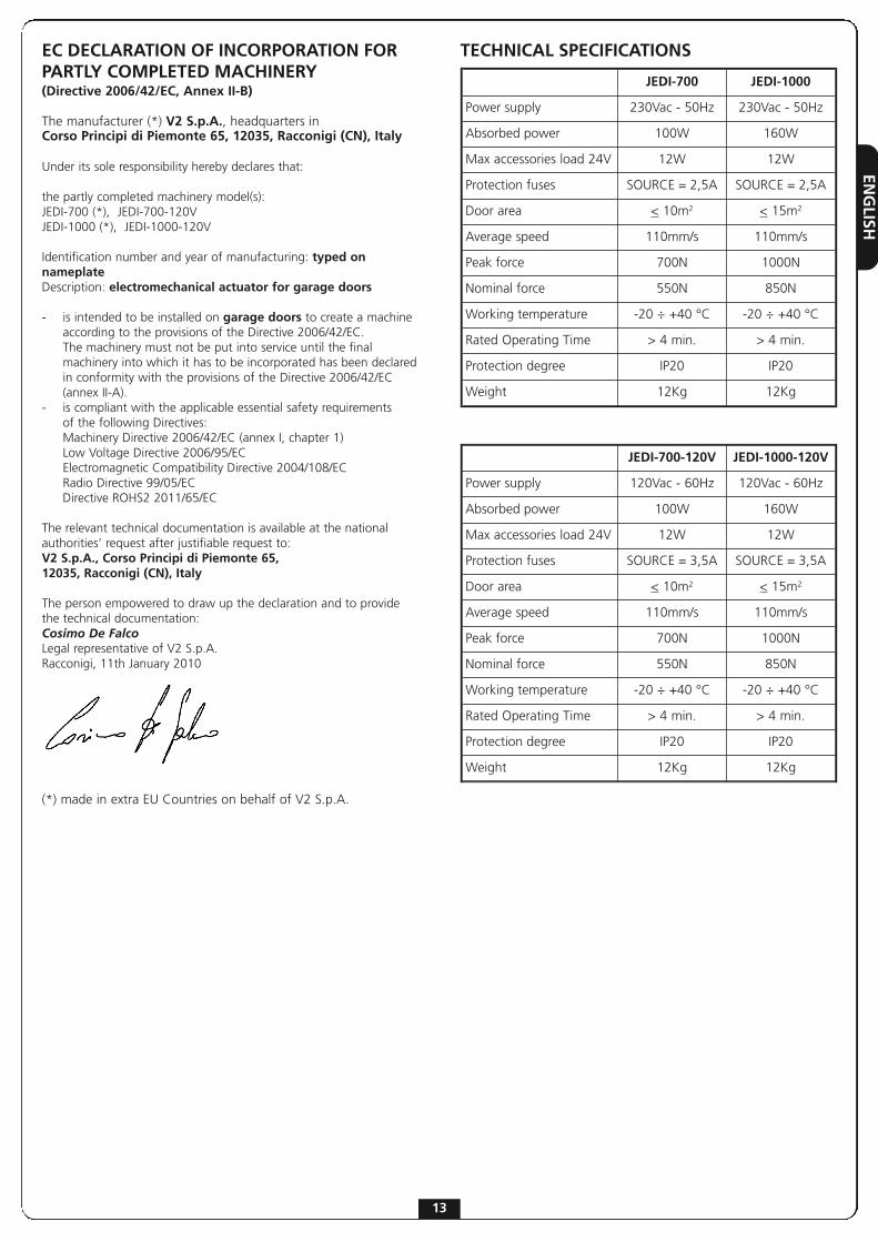
TECHNICAL SPECIFICATIONSEC DECLARATION OF INCORPORATION FORPARTLY COMPLETED MACHINERY(Directive 2006/42/EC, Annex II-B)
The manufacturer (*) V2 S.p.A., headquarters inCorso Principi di Piemonte 65, 12035, Racconigi (CN), Italy
Under its sole responsibility hereby declares that:
the partly completed machinery model(s): JEDI-700 (*), JEDI-700-120VJEDI-1000 (*), JEDI-1000-120V
Identification number and year of manufacturing: typed onnameplate Description: electromechanical actuator for garage doors
- is intended to be installed on garage doors to create a machine according to the provisions of the Directive 2006/42/EC. The machinery must not be put into service until the final machinery into which it has to be incorporated has been declared in conformity with the provisions of the Directive 2006/42/EC (annex II-A).
- is compliant with the applicable essential safety requirements of the following Directives:Machinery Directive 2006/42/EC (annex I, chapter 1)Low Voltage Directive 2006/95/ECElectromagnetic Compatibility Directive 2004/108/ECRadio Directive 99/05/ECDirective ROHS2 2011/65/EC
The relevant technical documentation is available at the nationalauthorities’ request after justifiable request to:V2 S.p.A., Corso Principi di Piemonte 65, 12035, Racconigi (CN), Italy
The person empowered to draw up the declaration and to providethe technical documentation:Cosimo De FalcoLegal representative of V2 S.p.A.Racconigi, 11th January 2010
(*) made in extra EU Countries on behalf of V2 S.p.A.
JEDI-700 JEDI-1000
Power supply 230Vac - 50Hz 230Vac - 50Hz
Absorbed power 100W 160W
Max accessories load 24V 12W 12W
Protection fuses SOURCE = 2,5A SOURCE = 2,5A
Door area < 10m2 < 15m2
Average speed 110mm/s 110mm/s
Peak force 700N 1000N
Nominal force 550N 850N
Working temperature -20 ÷ +40 °C -20 ÷ +40 °C
Rated Operating Time > 4 min. > 4 min.
Protection degree IP20 IP20
Weight 12Kg 12Kg
JEDI-700-120V JEDI-1000-120V
Power supply 120Vac - 60Hz 120Vac - 60Hz
Absorbed power 100W 160W
Max accessories load 24V 12W 12W
Protection fuses SOURCE = 3,5A SOURCE = 3,5A
Door area < 10m2 < 15m2
Average speed 110mm/s 110mm/s
Peak force 700N 1000N
Nominal force 550N 850N
Working temperature -20 ÷ +40 °C -20 ÷ +40 °C
Rated Operating Time > 4 min. > 4 min.
Protection degree IP20 IP20
Weight 12Kg 12Kg

ENGLISH
14
IMPORTANT REMARKSFor any installation problem please contact our Customer Serviceat the number +39-0172.812411 operating Monday to Fridayfrom 8:30 to 12:30 and from 14:00 to 18:00
V2 S.p.A. has the right to modify the product withoutprevious notice; it also declines any responsibility todamage or injury to people or things caused by improperuse or wrong installation.
m PLEASE READ THIS INSTRUCTION MANUAL VERYCAREFULLY BEFORE INSTALLING AND PROGRAMMINGYOUR CONTROL UNIT.
• This instruction manual is only for qualified technicians, whospecialize in installations and automations.
• The contents of this instruction manual do not concern theend user.
• Every programming and/or every maintenance service shouldbe done only by qualified technicians.
AUTOMATION MUST BE IMPLEMENTED IN COMPLIANCEWITH THE EUROPEAN REGULATIONS IN FORCE:
EN 60204-1 (Machinery safety. electrical equipment of machines, part 1: general rules)
EN 12445 (Safe use of automated locking devices, test methods)
EN 12453 (Safe use of automated locking devices, requirements)
• The installer must provide for a device (es. magnetotermicalswitch) ensuring the omnipolar sectioning of the equipmentfrom the power supply. The standards require a separation ofthe contacts of at least 3 mm in each pole (EN 60335-1).
• Installation requires mechanical and electrical skills,therefore it shall be carried out by qualified personnel only,who can issue the Compliance Certificate concerning thewhole installation (Machine Directive 98/37/EEC, Annex IIA).
• The automated vehicular gates shall comply with thefollowing rules: EN 12453, EN 12445, EN 12978 as well asany local rule in force.
• Also the automation upstream electric system shall complywith the laws and rules in force and be carried outworkmanlike. V2 S.p.A. declines any responsibility in case ofautomation upstream electric system not complying with thelaws and rules in force and not carried out workmanlike.
• The door thrust force adjustment shall be measured bymeans of a proper tool and adjusted according to the max.limits, which EN 12453 allows.
• The use of JEDI in dusty, saline or explosive environmentis forbidden
• The opener is designed for operation in dry rooms exclusively.
• For the safety and life of persons it is absolutely necessary tofollow all instructions.
• Keep these instructions save for later reference
• Do not permit children to play with the automated garagedoor. Transmitters are to be kept safe and away fromchildren!
• Only operate the door if the entire door area is in your field ofview. Always be sure, that no persons or objects are locatedwithin traveling range of the door.
• Do not use the opener when service or adjustment work isrequired. A badly balanced door, or a faulty garage doorsystem may cause injuries.
• Please inform all persons using the door system on how tooperate it correctly and safely. Demonstrate and test thereversion (with a 50 mm high obstacle at max. 150 N) as wellas the mechanical release.
• For the safety of persons and objects a safety check has to beperformed. Before finishing the initial operation make surethat the drive stops and reverses according to the valid norms(EN 12453) when hitting an obstacle (max. 150N force,equivalent to approx. 15 kg, more than 50 mm aboveground).
• This test and measurement of force may only be performed bya professional.When hitting an obstacle the door has to stop and reverse(completely or partially, depending on the setting of the PCB).If the door does not run the correct path or if the door doesnot reverse when hitting an obstacle the programming offorce and path has to be repeated.Then please repeat the test.If the door after the performed corrections does not stop andreverse according to the valid norms, the door may not beoperated automatically.
• Check regularly that the gate reverse when detected a40mm high obstacle
• Check often the automation, particularly the cables, springsand mechanic parts for wear and tear, damages andunbalancing
• The plug must be at easy reach, after the installation
• The data on the plate of the product are written on the labelput next to the connection terminal board
• Permanently mounted auxiliary devices (such as push buttonsetc.) should be mounted within view of the door.The distance between moving parts and the height must be atleast 1.5 meters. It is essential that they are mounted out ofreach of children!
• Affix warning signs indicating the risk of being caught in thedoor where they may be seen immediately or in the vicinity ofthe permanently mounted push button.

ENGLISH
15
PRELIMINARY CHECKINGS
Before installing JEDI, please check the following basic points:
• The door must be suitable to be automated (check the dooroperation manual and directions). The door structure itselfmust be stout and appropriate to be automated.
• Fix the engine steadily and using suitable material.
• If necessary, make the structural calculation and enclose tothe technical specification paper.
• Check the door to be provided with anti-fall system(independent of the suspension system)
• The door must be functional and safe.
• The door must open and close easily without any friction.
• The door must be properly balanced both before and after itsautomation: stopping the door in any position, it must notmove (carry out a balance weight adjustment, if necessary).
• It is advisable to install the geared motor in the centre of thedoor; it is permitted to move aside 100 mm to install thesliding arm accessory 162504 (see paragraph 3 page 18).
• In case of counterbalanced door, check that the minimumdistance between the track and the door must not be under20 mm.
INSTALLATION LAYOUT
� Photocellscable 4 x 0,5 mm2 (RX)cable 2 x 0,5 mm2 (TX)
� Inside push-buttot panel cable 3 x 0,5 mm2
� Schuco socket -
� Junction box -
� Actuator JEDI cable with plug 2 x 0.75 mm2
� Blinker cable 2 x 0.5 mm2
� Aerial cable RG-58
� Key switch cable 3 x 0.5 mm2

ENGLISH
16
INSTALLATION OF GUIDESECTION BAR
1. Remove the section bar from itscardboard packaging and check itsintegrity.
2. Unfold the section bar as indicated inthe figure below.
3. Once the section bar is elongated, slidethe connecting section bar R to the endposition indicated by the two holes Qon the chain-guide section bar.
4. Adjust the tension of the chain using theAllen-head screw with a 10 mmAllen-wrench: turn the bolt until thechain is sufficiently tight.
m CAUTION: Make certain that thedraw slide slides freely along the entirelength of the guide. Eliminate anyfriction prior to proceeding with thenext phases of installation.

ENGLISH
17
INSTALLATION OF MOTOR ON SECTION BAR
1. Insert the shaft/pinion adapter on the motor shaft.
2. Position the section bar A on the motor:the shaft/pinion adapter B must fit into the seat on thesection bar. Verify that the section bar fits snugglyagainst the motor.
3. Position the two omega brackets C on the section barso that they correspond with the holes on the base ofthe motor.
4. Fasten the two omega brackets using the 6 x 15self-threading screws provided D.
m In case of lack of space, the motor can bemounted rotated of 90°
INSTALLATION
2.1 Disassemble the door's locking system.
2.2 Measure the door, and at exactly half its height mark the reference points on the upper crossbeam and on the ceiling to facilitate positioning of the guide section bar.
2.3 Fasten the bracket E to the upper crossbeam of the door using plugs G suitable for the type of wall (ø minimum 8 mm).
2.4 Hook the section bar A to the bracket using the hexagonal-head F 6x80 screw with its self-blocking nut
2.5 Bend the 2 pierced bar at the desired length
2.6 Fix the front pierced bar H to the fixing bracket I in the section bar using the 8x20 screws L with their nuts
2.7 Fix the rear pierced bar M to the omega bracket Nusing the 8x20 screws L with their nuts
2.8 Following the references previously marked on the ceiling, locate the fixing points for the bars H and Mand using the screws O suitable for the type of ceiling (minimum ø 8 mm) anchor the automation

ENGLISH
2.9 Only for sectional and spring operated garage doors Fasten the draw slide I on the upper portion of the door maintaining the previously marked reference points. Connect the perforated bar L and the curved arm M using 2, 6 x 15 bolts. Connect the curved arm M and the draw plate I using the cylindrical headed pivot with the provided split pin.
3. Only for counter-weighted garage doorsFasten the arch arm 162504 on the upper portion of thedoor maintaining the previously marked reference points.The two anchor plates (upper and lower) of the arch162504 must be in the same plane. If not, add shims.Connect the perforated bar L to the perforated bar of thearch arm using 2, 6 x 15 bolts.
RELEASE OF THE AUTOMATIONIn order to release the automation from inside, pull the knobdownwards.
m CAUTION: Do not use the knob to open the door.It is prohibited to hand objects off the release cord.
In order to release the automation from outside, install theaccessory release kit (code 162518).
mWARNING: If the door is unlocked to be opened, whenit will be closed it is automatically locked for securityreasons.
If the power supply is not available, the door can be openedonly by acting again on the release knob.
If there are no secondary accesses to the garage werecommend the installation of the device to unlock from theoutside (code 162518)
18

ENGLISH
19
ELECTRICAL CONNECTIONS
The control panel inside JEDI is already cabled. You just need to plug it in the electrical outlet to proceed with operational parameter programming.
To connect the photocells and the START button, please refer to the following diagram:

ENGLISH
20
SET-UP OF OPERATIONALPARAMETERS
JEDI is equipped with a practical interface thatallows rapid and simple on-display programming
using four keys: , , +, -.
Preliminary operations:1. Move the door so as to hook on the drive
trolley.2. Power up the device: the courtesy light comes
on, the control unit emits a BEEP and the segments of the display are illuminated one at a
time until the display shows 0.
m PLEASE NOTE: if programming is notcompleted (by means of function 10. End programming) the parameters set arelost. If there is an error in the set parameters, simplypower off the device, restore power and thenrepeat the programming operation.
1.Setting the open limit switch
m PLEASE NOTE: The open limit switch must be stored prior to the close limit switch. If thisprocedure is used erroneously to set the close limit switch, the parameter is NOT stored.
Press the key for 5 seconds
When the door reaches thedesired position, press the
key to save the settings
The device emits a beep andthe display shows I Press the key:
I flashes
Press and hold the + (the door opens)
or - (the door closes) key to reach the fully open
position
2.Setting the close limit switch
Press the - key, the display shows 2
Press the key: 2 flashes
Press and hold the + (the door opens)
or - (the door closes) key to reach the fully
close position
When the door reaches theclosed position, wait 2
seconds, then press the key to save the settings
ENGLISH
21
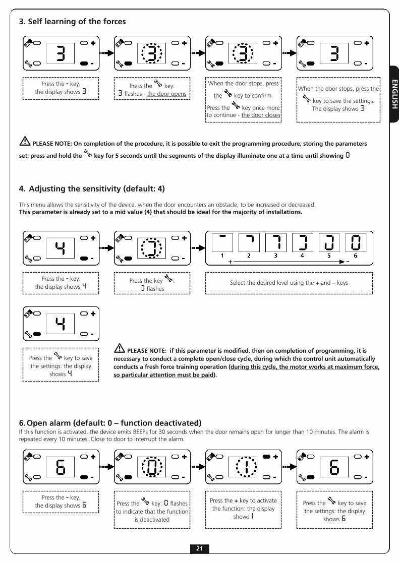
4. Adjusting the sensitivity (default: 4)
This menu allows the sensitivity of the device, when the door encounters an obstacle, to be increased or decreased.This parameter is already set to a mid value (4) that should be ideal for the majority of installations.
3. Self learning of the forces
Press the - key, the display shows 3
Press the key: 3 flashes - the door opens
When the door stops, press
the key to confirm.
Press the key once moreto continue - the door closes
When the door stops, press the
key to save the settings.The display shows 3
Press the - key, the display shows 4
Press the key : 0 flashes
Select the desired level using the + and – keys
m PLEASE NOTE: On completion of the procedure, it is possible to exit the programming procedure, storing the parameters
set: press and hold the key for 5 seconds until the segments of the display illuminate one at a time until showing 0
m PLEASE NOTE: if this parameter is modified, then on completion of programming, it isnecessary to conduct a complete open/close cycle, during which the control unit automaticallyconducts a fresh force training operation (during this cycle, the motor works at maximum force,so particular attention must be paid).
Press the key to save the settings: the display
shows 4
6.Open alarm (default: 0 – function deactivated)If this function is activated, the device emits BEEPs for 30 seconds when the door remains open for longer than 10 minutes. The alarm isrepeated every 10 minutes. Close to door to interrupt the alarm.
Press the - key, the display shows 6 Press the key: 0 flashes
to indicate that the functionis deactivated
Press the + key to activatethe function: the display
shows IPress the key to save the settings: the display
shows 6

ENGLISH
22
Press the - key, the display shows 8 Press the key: 0 flashes
to indicate that the functionis deactivated
Press the + key to activatethe function: the display
shows IPress the key to save the settings: the display
shows 8
7.Automatic closure (default: 0 – function deactivated)If this function is activated, the device automatically closes the door after the set period of time. Prior to closing the door, the device emits BEEPs for 20 seconds.
Press the - key, the display shows 7 Press the key: 0 flashes
to indicate that the function is deactivated
Press the + key to activatethe function: the displayshows I corresponding to
30 seconds
Select the desired pause time using the + and – keys Press the key to save the settings: the display
shows 7
8.Maintenance alarm (default: 0 – function deactivated)If this function is activated, the device emits BEEPs when the motor reaches 2000 operational cycles. This alarm may be useful for scheduling maintenance operations.To interrupt the alarm , simply press and hold the START button for 5 seconds, or power off the device for several seconds.
Press the - key, the display shows 9 Press the key: 0 flashes
to indicate that the functionis deactivated
Press the + key to activatethe function: the display
shows IPress the key to save the settings: the display
shows 9
9.Condominium function (default: 0 - function disabled)
m CAUTION: To enable the condominium function it is necessary to activate automatic closing
The condominium function provides the following operation logics:1 - during the opening phase any start command is ignored2 - during a pause a start command re-charge the pause time3 - during the closing phase a start command causes the door movement to reverse
ENGLISH
23
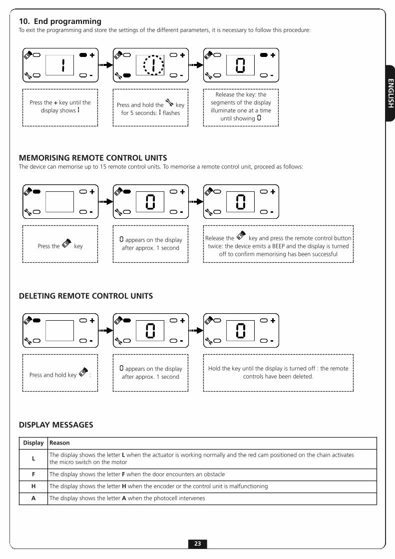
10. End programmingTo exit the programming and store the settings of the different parameters, it is necessary to follow this procedure:
Press the + key until thedisplay shows I Press and hold the key
for 5 seconds: I flashes
Release the key: thesegments of the displayilluminate one at a time
until showing 0
DELETING REMOTE CONTROL UNITS
MEMORISING REMOTE CONTROL UNITSThe device can memorise up to 15 remote control units. To memorise a remote control unit, proceed as follows:
Press the key0 appears on the displayafter approx. 1 second
Release the key and press the remote control buttontwice: the device emits a BEEP and the display is turned
off to confirm memorising has been successful
Press and hold key :0 appears on the displayafter approx. 1 second
Hold the key until the display is turned off : the remotecontrols have been deleted.
Display Reason
LThe display shows the letter L when the actuator is working normally and the red cam positioned on the chain activates the micro switch on the motor
F The display shows the letter F when the door encounters an obstacle
H The display shows the letter H when the encoder or the control unit is malfunctioning
A The display shows the letter A when the photocell intervenes
DISPLAY MESSAGES

ENGLISH
24