ivanpah solar electric generating facility (isegf)€¦ · 30/09/2011 · bechtel document no....
TRANSCRIPT
Bechtel Document No. 25542-000-30R-K01G-00001-000
Bechtel Confidential Confidential. © 2010 Bechtel Power Corporation. This document, prepared under Contract 25542 between Bechtel Power Corporation and the Owners of the Ivanpah 1, Ivanpah 2, and Ivanpah 3 solar power projects, contains information confidential and/or proprietary to Bechtel Power Corporation that is not to be used, disclosed, or reproduced in any form by any person or entity other than Bechtel Power Corporation or the Owners of the Ivanpah 1, Ivanpah 2, and Ivanpah 3 solar power projects without Bechtel Power Corporation’s prior written permission. All rights reserved. This document has been prepared by Bechtel Power Corporation exclusively for the Owners of the Ivanpah 1, Ivanpah 2, and Ivanpah 3 solar power projects under Contract 25542 and is not to be relied upon by any person or entity other than the Owners of the Ivanpah 1, Ivanpah 2, and Ivanpah 3 solar power projects or used in conjunction with any other project.
Ivanpah Solar Electric Generating Facility (ISEGF)
Docket Number: 07-AFC-5 CACA-48668, 49503, and 49504)
Drainage Erosion and Sediment
Control Plan Phase 1
Ivanpah 1 and Common Logistic Area Construction and
Site Mobilization for Ivanpah 2 and Ivanpah 3
(Condition of Certification S&W-1)
Submitted to the following agencies:
County of San Bernardino Regional Water Quality Control Board
Bureau of Land Management and the California Energy Commission
Chief Building Official
Submitted by
Bechtel Power on behalf of Solar Partners I, LLC; Solar Partners II, LLC; and Solar Partners VIII, LLC
June 15th, 2010
Bechtel Document No. 25542-000-30R-K01G-00001-000
Confidential. © 2010 Bechtel Power Corporation. All Rights Reserved
ii
TABLE OF CONTENTS 1.0 Introduction ........................................................................................................................ 1
1.1 Drainage, Erosion, and Sediment Control Plan Elements.............................................. 2 1.2 Regulatory Background ................................................................................................. 3
1.2.1 Federal Clean Water Act ........................................................................................... 3 1.2.2 Porter-Cologne Water Quality Control Act ............................................................... 3 1.2.3 San Bernardino County Regulations.......................................................................... 4
1.3 Project Overview............................................................................................................ 4 1.3.1 Project Description .................................................................................................... 4 1.3.2 Land Occupancy ........................................................................................................ 4 1.3.3 Heliostat Arrays ......................................................................................................... 5 1.3.4 Power Blocks ............................................................................................................. 5 1.3.5 Substation .................................................................................................................. 6 1.3.6 Common Administrative Area................................................................................... 6 1.3.7 Access Roads and Service Paths................................................................................ 6
1.4 Watercourses and Other Critical Areas.......................................................................... 7 1.4.1 Watercourses ............................................................................................................. 7 1.4.2 Other Critical Areas................................................................................................... 7
2.0 Hydrology........................................................................................................................... 8 2.1 Precipitation ................................................................................................................... 8 2.2 Drainage......................................................................................................................... 8 2.3 Hydraulic and Hydrology Calculations and Memorandum ......................................... 10
3.0 Clearing and Grading ....................................................................................................... 11 3.1 Areas to be Cleared and Graded .................................................................................. 11
3.1.1 Linear Facilities ....................................................................................................... 12 3.2 Location of Disposal Areas, Fills or Other Special Areas ........................................... 13 3.3 Existing and Proposed Topography ............................................................................. 13 3.4 Volumes of Cut and Fill............................................................................................... 13
4.0 Project Schedule ............................................................................................................... 14 4.1 Mobilization................................................................................................................. 15 4.2 Heliostat Erection......................................................................................................... 15 4.3 Power Block and Towers ............................................................................................. 16
5.0 Best Management Practices.............................................................................................. 16 5.1 General Erosion Control Measures .............................................................................. 16
5.1.1 Access Road, Entrance and Parking, and Laydown Areas/ Offsite Vehicle Tracking 18 5.1.2 Dust Suppression and Control ................................................................................. 19 5.1.3 ISEGF Site and Linear Facilities ............................................................................. 19 5.1.4 Site Stabilization and Demobilization ..................................................................... 20
5.2 Other Controls.............................................................................................................. 21 5.2.1 Material Handling and Storage................................................................................ 21 5.2.2 Foundations ............................................................................................................. 22 5.2.3 Solid and Hazardous Waste Management ............................................................... 22
5.2.3.1 Nonhazardous Solid Waste ............................................................................. 23 5.2.3.2 Wastewater...................................................................................................... 23 5.2.3.3 Hazardous Waste ............................................................................................ 24
5.2.4 Potential Contaminated Soil .................................................................................... 24 5.2.5 Groundwater/Dewatering Controls.......................................................................... 25
6.0 References ........................................................................................................................ 25 7.0 Appendices ....................................................................................................................... 26
Bechtel Document No. 25542-000-30R-K01G-00001-000
Confidential. © 2010 Bechtel Power Corporation. All Rights Reserved
iii
Tables 1. Estimated Cut & Fill Quantities 2. Project Schedule Major Milestones 3. Ivanpah 1 and Common Area Schedule of Major Construction Activities APPENDICES Appendix 1 – Figures Figure 1 – 25542-000-C2-0000-00002-000, Vicinity Map Figure 2 – 25542-000-C2-0000-00001-004 Site Plan Figure 3 – 25542-000-C2-0010-00001-000 Units 1, 2, & Common Fence Plan Figure 4 – 25542-000-C2-0010-00002-000 Ivanpah 2 and Ivanpah 3 Fencing Plan Figure 5 – 25542-000-C2-0010-00003-000 Construction Facilities Layout Arrangement Power
Block Typical Figure 6 – 25542-009-C2-0010-00002-000 Construction Facilities Layout Arrangement Common
Area Figure 7 – 25542-000-C2-0000-00003-000 Topography Map Figure 8 – 25542-000-CG-0090-00001-000 Grading and Surface Details for Ephemeral Wash
Crossing Figure 9 – 25542-001-CG-0010-00001-000 Ivanpah 1 Power Block Rough Grading Plan Figure 10 – 25542-000-CG-0090-00002-000 Ivanpah 1 Power Block Rough Grading Sections Figure 11 – 25542-009-CG-0010-00001-000 Ivanpah Common Area SCE Switchyard Rough
Grading Plan Figure 12 – 25542-009-CG-0010-00002-000 Ivanpah Common Area Administration Building
and Wells Rough Grading Plan Figure 13 – 25542-009-CG-0010-00003-000 Ivanpah Common Area Heliostat Building and
Laydown Area Rough Grading Plan Figure 14 – 25542-009-CG-0090-00001-000 Common Area Switchyard Rough Grading Sections
and Details Figure 15 – 25542-009-CG-0090-00002-000 Administration Building and Well Area- Rough
Grading Sections & Detail Figure 16 – 25542-009-CG-0090-00003-000 Heliostat Building and Laydown Area – Sections &
Detail Figure 17 – 25542-001-CG-0011-00001-000 Ivanpah 1 Category 2 Wash Crossings Figure 18 – 25542-001-CG-0011-00002-000 Ivanpah 1 Category 3 Wash Crossings Figure 19 – 25542-000-CD-0000-00001-000 Hydrology Map Pre-Development Figure 20 – 25542-000-CD-0000-00002-000 Ivanpah 1 & Common Area – Hydrology Plan -
Post Development Figure 21 – 25542-001-CD-0000-00001-000 Hydrology Map Post-Development Power Block Figure 22 – 25542-009-CD-0000-00001-000 Ivanpah Common Area – Administration
Building/Well Hydrology Plan – Post Development Figure 23 – 25542-000-CE-0010-00001-000 Ivanpah 1 and Common Area Erosion and Sediment
Control Plan Figure 24 – 25542-000-C0-0090-00001-000 Site Work Sheet 1 – Notes, Legend & Details Figure 25 – 25542-000-C0-0090-00002-000 Site Work Sheet 2 – Erosion & Sediment
ControlSections and Details Figure 26 – 25542 -000-C0-0090-00003-000 Site Work Sheet 3 – Typical Fencing Sections &
Details Figure 27 – 25542-000-C0-0090-00004-000 Site Work Sheet 4 – Typical Grading & Surfacing
Details
Bechtel Document No. 25542-000-30R-K01G-00001-000
Confidential. © 2010 Bechtel Power Corporation. All Rights Reserved
iv
Figure 28 – 25542-000-C0-0090-00005-000 Site Work Sheet 5 – Typical Grading & Surfacing Details
Figure 29 – 25542-000-C0-0090-00006-000 Site Work Sheet 6 – Typical Grading & Surfacing Details
Figure 30 – 25542-000-CS-0010-00001-000 Road Grading and Paving Plan Colosseum Rd Station 0-00 to 10-04 Sheet 1
Figure 31 – 25542-000-CS-0010-00002-000 Road Grading and Paving Plan Colosseum Rd Station 10-04 to 35-27 Sheet 2
Figure 32 – 25542-000-CS-0010-00003-000 Road Grading and Paving Plan Colosseum Rd Station 35-27 to 56-76 Sheet 3
Figure 33 – 25542-000-CS-0010-00004-000 Road Grading and Paving Plan Colosseum Rd Station 56-76 to 78-12 Sheet 4
Figure 34 – 25542-000-CS-0010-00005-000 Road Grading and Paving Plan Colosseum Rd Station 78-12 to 105-34 Sheet 5
Figure 35 – 25542-000-CS-0010-00006-000 Road Grading and Paving Plan Unit 1 Rd Station 4-09 to 25-57 Sheet 6
Figure 36 – 25542-000-CS-0010-00007-000 Road Grading and Paving Plan Unit 1 Rd Station 25-57 to 50-28 Sheet 7
Figure 37 – 25542-000-CS-0010-00008-000 Road Grading and Paving Plan Unit 1 Rd Station 50-27 to 59-69 Sheet 8
Figure 38 – 25542-000-CS-0010-00009-000 Road Grading and Paving Plan Unit 1 Rd Station 59-69 to 126-65 Sheet 9
Figure 39 – 25542-000-CS-0010-000012-000 Road Grading and Paving Plan Unit 1 Rd Station 126-65 to 141-65 Sheet 12
Figure 40 – 25542-001-CS-0010-00001-000 Power Block Road Grading and Paving Figure 41 – 25542-000-CS-0090-00001-000 Colosseum Road Profile – Sheet 1 Figure 42 – 25542-000-CS-0090-00002-000 Colosseum Road Profile – Sheet 2 Figure 43 – 25542-000-CS-0090-00003-000 Colosseum Road Profile – Sheet 3 Figure 44 – 25542-000-CS-0090-00004 Colosseum Road Alignment Figure 45 – 25542-000-CS-0090-00005-000 Unit 1 Road Profile Figure 46 – 25542-000-CS-0090-00006-000 Unit 1 Road Alignment Figure 47 – 25542-000-CS-0090-00007-000 Switchyard Road Profile Figure 48 – 25542-001-CS-0011-00001-000 Ivanpah 1 Dirt Road and Heliostat Maintenance Path
Plan Appendix 2 – Calculations and Memorandums 25542-001-CGC-CG00-00001-000 Ivanpah 1 power block and administration
building drainage sizing 25542-009-CGC-CG00-00001-001 Ivanpah 1 Power Block and Common Area
Diversion Channels Hydraulic Design 25542-000-G27-GZC-00112-000 Technical Memorandum 16 - Stormwater
Design Flows for Ivanpah 1 and Common Area Diversion Channels
25542-000-G27-GZC-00116-000 Technical Memorandum No. 18 - Summary of Stormwater Runoff and Sediment Transport Analysis
Appendix 3 – Project Specification 25542-000-3PS-CE01-00001-002
Technical Specification for Earthwork, Grading, Filling, and Backfilling (including trenching and backfilling)
Bechtel Document No. 25542-000-30R-K01G-00001-000
Confidential. © 2010 Bechtel Power Corporation. All Rights Reserved
v
Appendix 4 – BMP Fact Sheets
25542-000-G27-GGG-00005-001 California Stormwater Best Management Practices Handbook - Water Conservation Practices
25542-000-G27-GGG-00006-001 California Stormwater Best Management Practices Handbook - Dewatering Operations
25542-000-G27-GGG-00007-001 California Stormwater Best Management Practices Handbook - Paving and Grinding Operations
25542-000-G27-GGG-00008-001 California Stormwater Best Management Practices Handbook - Vehicle and Equipment Cleaning
25542-000-G27-GGG-00009-001 California Stormwater Best Management Practices Handbook -Vehicle and Equipment Fueling
25542-000-G27-GGG-00010-001 California Stormwater Best Management Practices Handbook - Vehicle and Equipment Maintenance
25542-000-G27-GGG-00011-001 California Stormwater Best Management Practices Handbook - Scheduling
25542-000-G27-GGG-00012-001 California Stormwater Best Management Practices Handbook -Preservation of Existing Vegetation
25542-000-G27-GGG-00013-001 California Stormwater Best Management Practices Handbook - Earth Dikes and Drainage Swales
25542-000-G27-GGG-00014-001 California Stormwater Best Management Practices Handbook -Velocity Dissipation Devices
25542-000-G27-GGG-00015-001 California Stormwater Best Management Practices Handbook - Geotextiles and Mats
25542-000-G27-GGG-00016-001 California Stormwater Best Management Practices Handbook - Concrete Curing
25542-000-G27-GGG-00017-001 California Stormwater Best Management Practices Handbook - Concrete Finishing
25542-000-G27-GGG-00018-001 California Stormwater Best Management Practices Handbook - Silt Fence
25542-000-G27-GGG-00019-001 California Stormwater Best Management Practices Handbook - Check Dams
25542-000-G27-GGG-00020-001 California Stormwater Best Management Practices Handbook - Fiber Rolls
25542-000-G27-GGG-00021-001 California Stormwater Best Management Practices Handbook -Street Sweeping and Vacuuming
25542-000-G27-GGG-00022-001 California Stormwater Best Management Practices Handbook - Stabilized Construction Entrance/Exit
25542-000-G27-GGG-00023-001 California Stormwater Best Management Practices Handbook - Stabilized Construction Roadway
25542-000-G27-GGG-00024-001 California Stormwater Best Management Practices Handbook - Entrance/Outlet Tire Wash
25542-000-G27-GGG-00025-001 California Stormwater Best Management Practices Handbook -Wind Erosion Control
25542-000-G27-GGG-00026-001 California Stormwater Best Management Practices Handbook - Material Delivery and Storage
25542-000-G27-GGG-00027-001 California Stormwater Best Management Practices Handbook - Material Use
25542-000-G27-GGG-00028-001 California Stormwater Best Management Practices Handbook -Stockpile Management
25542-000-G27-GGG-00029-001 California Stormwater Best Management Practices Handbook -Spill Prevention and Control
Bechtel Document No. 25542-000-30R-K01G-00001-000
Confidential. © 2010 Bechtel Power Corporation. All Rights Reserved
vi
25542-000-G27-GGG-00030-001 California Stormwater Best Management Practices Handbook - Solid Waste Management
25542-000-G27-GGG-00031-001 California Stormwater Best Management Practices Handbook - Hazardous Waste Management
25542-000-G27-GGG-00032-001 California Stormwater Best Management Practices Handbook -Contaminated Soil Management
25542-000-G27-GGG-00033-001 California Stormwater Best Management Practices Handbook -Concrete Waste Management
25542-000-G27-GGG-00034-001 California Stormwater Best Management Practices Handbook -Sanitary/Septic Waste Management
25542-000-G27-GGG-00035-001 California Stormwater Best Management Practices Handbook - Liquid Waste Management
Appendix 5 – Regulations from the County of San Bernardino, California,
Department of Fish and Game, and Lahontan Regional Water Quality Control Board
25542-000-G27-GGG-00036-001 California Regional Water Quality Control Board - Lahontan Region - Facts, Requirements, Surface Water Monitoring and Reporting Program
25542-000-G27-GGG-00037-001 State of California Memorandum - Comments on the Preliminary Staff Assessment and Recommendations for the Final Staff Assessment
25542-000-G27-GGG-00038-001 San Bernardino County - Land Use Services Department - Comments to the Ivanpah Electric Generation System Application for Certification
25542-000-G27-GGG-00039-001 California Regional Water Quality Control Board - Lahontan Region - Comments on the Application for Certification Requesting 4 Separate Certifications to Construct and Operate Ivanpah Solar Electric Generating System
25542-000-G27-GGG-00040-001 Guidelines for Clearance and Translocation of Desert Tortoises from the Ivanpah Solar Electric Generating System (ISEGS) Project
25542-000-G27-GGG-00041-001 San Bernardino County - Department of Public Works - Finds that the Environmental Analysis Concerning all Solid Waste Generated by the Proposed Project is Adequate
Appendix 6 – Risk Level Determination in accordance with Appendix 1 of the
California Construction General Permit Order 2009-0009-DWQ adopted on September 2, 2009
Bechtel Document No. 25542-000-30R-K01G-00001-000
Confidential. © 2010 Bechtel Power Corporation. All Rights Reserved
1
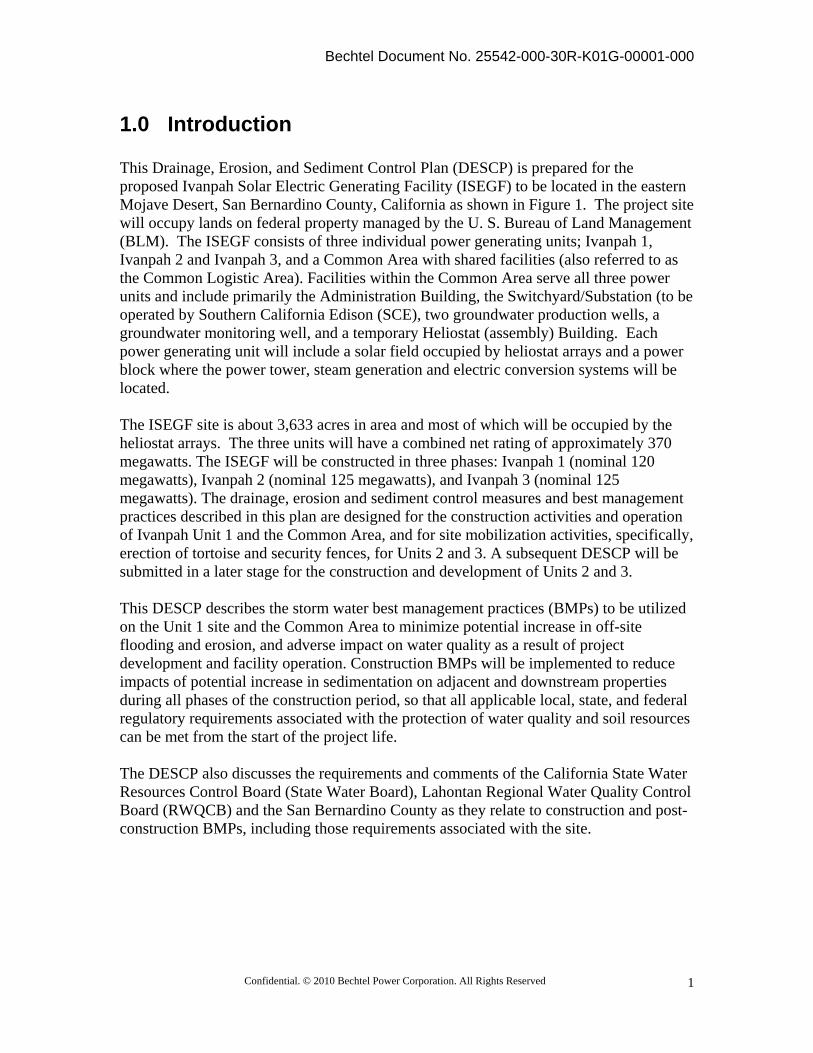
1.0 Introduction This Drainage, Erosion, and Sediment Control Plan (DESCP) is prepared for the proposed Ivanpah Solar Electric Generating Facility (ISEGF) to be located in the eastern Mojave Desert, San Bernardino County, California as shown in Figure 1. The project site will occupy lands on federal property managed by the U. S. Bureau of Land Management (BLM). The ISEGF consists of three individual power generating units; Ivanpah 1, Ivanpah 2 and Ivanpah 3, and a Common Area with shared facilities (also referred to as the Common Logistic Area). Facilities within the Common Area serve all three power units and include primarily the Administration Building, the Switchyard/Substation (to be operated by Southern California Edison (SCE), two groundwater production wells, a groundwater monitoring well, and a temporary Heliostat (assembly) Building. Each power generating unit will include a solar field occupied by heliostat arrays and a power block where the power tower, steam generation and electric conversion systems will be located. The ISEGF site is about 3,633 acres in area and most of which will be occupied by the heliostat arrays. The three units will have a combined net rating of approximately 370 megawatts. The ISEGF will be constructed in three phases: Ivanpah 1 (nominal 120 megawatts), Ivanpah 2 (nominal 125 megawatts), and Ivanpah 3 (nominal 125 megawatts). The drainage, erosion and sediment control measures and best management practices described in this plan are designed for the construction activities and operation of Ivanpah Unit 1 and the Common Area, and for site mobilization activities, specifically, erection of tortoise and security fences, for Units 2 and 3. A subsequent DESCP will be submitted in a later stage for the construction and development of Units 2 and 3. This DESCP describes the storm water best management practices (BMPs) to be utilized on the Unit 1 site and the Common Area to minimize potential increase in off-site flooding and erosion, and adverse impact on water quality as a result of project development and facility operation. Construction BMPs will be implemented to reduce impacts of potential increase in sedimentation on adjacent and downstream properties during all phases of the construction period, so that all applicable local, state, and federal regulatory requirements associated with the protection of water quality and soil resources can be met from the start of the project life. The DESCP also discusses the requirements and comments of the California State Water Resources Control Board (State Water Board), Lahontan Regional Water Quality Control Board (RWQCB) and the San Bernardino County as they relate to construction and post-construction BMPs, including those requirements associated with the site.
Bechtel Document No. 25542-000-30R-K01G-00001-000
Confidential. © 2010 Bechtel Power Corporation. All Rights Reserved
2
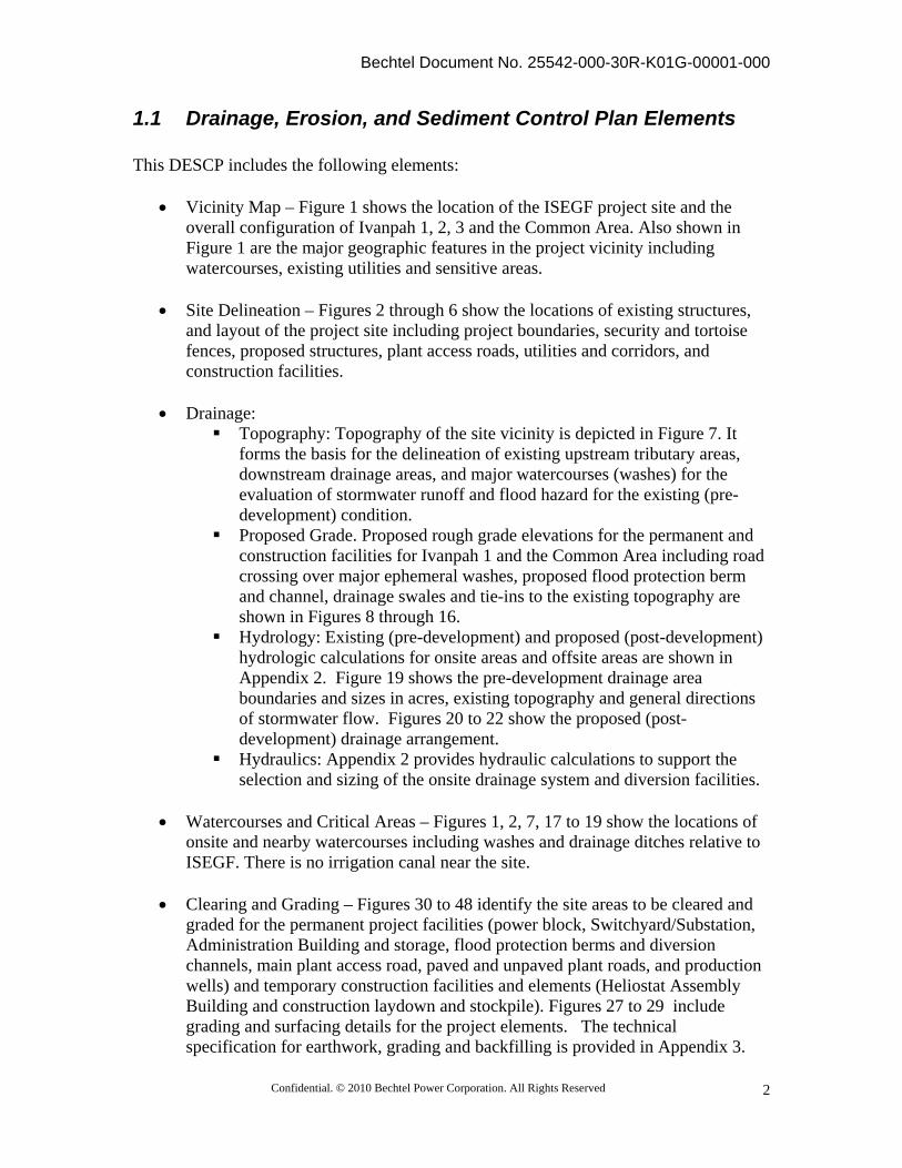
1.1 Drainage, Erosion, and Sediment Control Plan Elements This DESCP includes the following elements:
Vicinity Map – Figure 1 shows the location of the ISEGF project site and the overall configuration of Ivanpah 1, 2, 3 and the Common Area. Also shown in Figure 1 are the major geographic features in the project vicinity including watercourses, existing utilities and sensitive areas.
Site Delineation – Figures 2 through 6 show the locations of existing structures,
and layout of the project site including project boundaries, security and tortoise fences, proposed structures, plant access roads, utilities and corridors, and construction facilities.
Drainage:
Topography: Topography of the site vicinity is depicted in Figure 7. It forms the basis for the delineation of existing upstream tributary areas, downstream drainage areas, and major watercourses (washes) for the evaluation of stormwater runoff and flood hazard for the existing (pre-development) condition.
Proposed Grade. Proposed rough grade elevations for the permanent and construction facilities for Ivanpah 1 and the Common Area including road crossing over major ephemeral washes, proposed flood protection berm and channel, drainage swales and tie-ins to the existing topography are shown in Figures 8 through 16.
Hydrology: Existing (pre-development) and proposed (post-development) hydrologic calculations for onsite areas and offsite areas are shown in Appendix 2. Figure 19 shows the pre-development drainage area boundaries and sizes in acres, existing topography and general directions of stormwater flow. Figures 20 to 22 show the proposed (post-development) drainage arrangement.
Hydraulics: Appendix 2 provides hydraulic calculations to support the selection and sizing of the onsite drainage system and diversion facilities.
Watercourses and Critical Areas – Figures 1, 2, 7, 17 to 19 show the locations of
onsite and nearby watercourses including washes and drainage ditches relative to ISEGF. There is no irrigation canal near the site.
Clearing and Grading – Figures 30 to 48 identify the site areas to be cleared and
graded for the permanent project facilities (power block, Switchyard/Substation, Administration Building and storage, flood protection berms and diversion channels, main plant access road, paved and unpaved plant roads, and production wells) and temporary construction facilities and elements (Heliostat Assembly Building and construction laydown and stockpile). Figures 27 to 29 include grading and surfacing details for the project elements. The technical specification for earthwork, grading and backfilling is provided in Appendix 3.
Bechtel Document No. 25542-000-30R-K01G-00001-000
Confidential. © 2010 Bechtel Power Corporation. All Rights Reserved
3
Soil Wind and Water Erosion Control – The general layout and details of the drainage, wind and water erosion and sediment controls for Ivanpah 1 and the Common Area are shown in Figures 23 to 25. Typical fencing sections and details are shown in Figure 26. A description of the BMPs proposed for the site is given in Section 5 and the relevant BMP fact sheets are included in Appendix 4.
1.2 Regulatory Background The Project will comply with all local, state, and federal regulatory requirements associated with the protection of water quality and soil resources. The following subsections discuss the major requirements of the laws, ordinances, regulations and standards related to the DESCP.
1.2.1 Federal Clean Water Act The federal Water Pollution Control Act, commonly referred to as the Clean Water Act (CWA), established the basic structure for regulating the pollution discharges into the nation’s waters and regulating the quality standards for the surface waters. Under the CWA, the U.S. Environmental Protection Agency implemented National Pollutant Discharge Elimination System (NPDES) program to protect water quality of receiving waters. Under Section 402, discharge of pollutants to receiving waters is prohibited unless the discharge is in compliance with an NPDES permit. The CWA allowed EPA to authorize the NPDES Permit Program to state governments, enabling states to perform many of the permitting, administrative, and enforcement aspects of the NPDES Program.
1.2.2 Porter-Cologne Water Quality Control Act The State of California established its regulations under the Porter-Cologne Water Quality Control Act (the Act) to comply with the CWA. The Act established the State Water Resources Control Board (State Water Board) and its nine Regional Water Quality Control Boards (Regional Boards) as the principal state agencies with primary responsibility for the coordination and control of water quality in California. The State Water Board sets the statewide policy for the implementation of federal and state laws and regulations. The Regional Boards adopt and implement the policy through the Water Quality Control Plans (Basin Plans). Under Section 13200, the project site is located within the boundaries of the Lahontan Regional Water Quality Control Board. The discharges from the project site during operations will be regulated under a new, individual NPDES permit for industrial activities (operations are addressed in the project’s Industrial Stormwater Pollution Prevention Plan) and under a statewide general permit for stormwater discharges from construction and land disturbance activities discussed in this document. The State Water Board has issued a new permit regulation under Order No. 2009-0009-DWQ, NPDES NO. CAS000002, which will be effective on July1, 2010. The ISEGF project, a Risk Level 1 discharger as determined in Appendix 6, will comply with the applicable requirements set forth in the new permit regulation.
Bechtel Document No. 25542-000-30R-K01G-00001-000
Confidential. © 2010 Bechtel Power Corporation. All Rights Reserved
4
1.2.3 San Bernardino County Regulations The San Bernardino County set its regulations and procedures for soil erosion and sediment control plans/permits under the 2009 amended San Bernardino County Development Code Chapters 82.13.080 and 85.11. The requirements are covered by the DESCP requirements proposed by the California Energy Commission (CEC) for the ISEGF project. For the water quality management, the County has its guidelines under the Model Water Quality Management Plan Guidance (WQMP Guidance). In this guidance, the California Stormwater Quality Association’s Stormwater Best Management Practices Handbook for New Development and Redevelopment (CASQA, 2003a) and the Stormwater Best Management Practices Handbook for Industrial and Commercial (CASQA, 2003b) are cited as acceptable for use in the development of BMPs for WQMP.
1.3 Project Overview
1.3.1 Project Description
ISEGF will consist of three independent solar thermal-electric power plant units that will be located approximately 1.6 mi west of the Ivanpah Dry Lake and 4.5 mi southwest of Primm, Nevada, in San Bernardino County, California. The project site will be located on federal property managed by the U.S. Bureau of Land Management. The three ISEGF power plants will have a combined net rating of approximately 370 megawatts. The ISEGF will be constructed in three phases: Ivanpah 1 (nominal 120 megawatts), Ivanpah 2 (nominal 125 megawatts), and Ivanpah 3 (nominal 125 megawatts). Figure 1 shows the location of the project and the locations of existing and proposed pipelines and roads. Locations of watercourses and critical areas such as ephemeral washes are shown in Figures 18 to 20. A site plan is provided in Figures 2. All figures are included in Appendix 1. Geotechnical field exploration (Converse, 2009) conducted for the project indicated the site consisted mostly of undeveloped land and was characterized by alluvial fan deposits and associated erosion features trending in an easterly direction. The subsurface native soils encountered at the site generally consist of silty sands with varying amounts of gravel, cobbles and boulders. The depth of groundwater is expected to be greater than 100 feet and is not anticipated to be a factor during construction. Construction dewatering is not considered necessary.
1.3.2 Land Occupancy
The ISEGF project (for all three units and the Common Areas) will occupy approximately 3,633 acres (Figures 3 through 7). Ivanpah 1 will require about 914 acres (1.43 mi2) and Ivanpah 2 will require about 1,097 acres (1.71 mi2), while Ivanpah 3 will require about 1, 227 acres (1.92 mi2). The project boundary for Ivanpah 1, 2, and 3 will cover a total of 3,238 acres (5.06 mi2). The Common Area, situated between Ivanpah 1
Bechtel Document No. 25542-000-30R-K01G-00001-000
Confidential. © 2010 Bechtel Power Corporation. All Rights Reserved
5
and 2 will occupy approximately 374 acres and will include the Southern California Edison substation, a nursery and rare plant storage area, and shared facilities (administration/ storage building, groundwater production wells). Portions of this construction logistics area will be used during construction for staging and temporary offices. The remaining 22 acres are land that will be disturbed for the construction of plant roads including the improvement of the Colosseum Road (from Primm Valley Golf Club to site), and construction of the gas line.
1.3.3 Heliostat Arrays Each power plant will be surrounded by heliostat arrays. The 120-megawatt plant (Ivanpah 1) will have heliostat arrays consisting of up to 53,500 heliostats. The 125-megawatt plant (Ivanpah 2 and 3) will each have heliostat arrays consisting of up to 60,000 heliostats. The heliostat arrays will be arranged around a single centralized solar power tower. The heliostats will automatically track the sun throughout the day and reflect the solar energy to the boiler on top of the tower. Each heliostat mirror is 7.2 ft (2.2 m) wide by 10.5 ft (3.2 m) high, yielding a reflecting surface of 76 ft2 (7 m2). Each heliostat consists of two mirrors mounted on a single pylon, along with a computer-programmed aiming control system that directs the motion of the heliostat to track the movement of the sun. The pylons will be fabricated from 6-inch pipe, and they will be embedded in the ground so as to resist lateral forces due to wind or flood flows. The methodology selected for field installation of pylons requires pre-augering a hole in the ground using drilling equipment mounted on an excavator (drill rig). The spoils will be knocked back to the hole to prepare for pylon insertion. Pylon insertion will be accomplished by an excavator equipped with specialized equipment that inserts the pylon. No construction water will be required or discharged with this insertion methodology. The drill rigs will be operated to minimize soil disturbance.
1.3.4 Power Blocks Each power plant unit will have a solar power tower, steam-turbine generator, an air-cooled condenser and auxiliary systems, which collectively are referred to as the power block. The tower supports the receiving boiler and moves steam to the turbines near its base. The combined height of towers and boiler will be about 460 ft. For each power plant, the power-block lateral dimensions will be about 650 ft wide by about 450 ft long, which represents an area of about 6.7 acres. The power block for each unit will be graded with moderate slopes to direct runoff to swale/ditches and pass stormwater through the oil/water separators before releasing flow to outlet aprons, where placement of stone rip-rap will prevent local erosion and reinstate natural sheet flow conditions toward downstream. The treatment flow rates of the oil-water separators are sized based on the target BPM design flow requirements established in Attachment D of the San Bernardino County Water Quality Model Plan and are documented in Appendix 2. Each power block will be protected by a flood protection berm and associated diversion channel, which are designed for a 100-year storm event. For Ivanpah 1, details of the protection berm and diversion channel are shown in Figures 9 and 10.
Bechtel Document No. 25542-000-30R-K01G-00001-000
Confidential. © 2010 Bechtel Power Corporation. All Rights Reserved
6
1.3.5 Substation Ivanpah 1, 2, and 3 will be connected to the nearby existing Southern California Edison transmission line. A substation located in the Common Area between Ivanpah 1 and 2 will be constructed to connect the ISEGF to the transmission line. The substation dimensions will be about 870 ft wide by 900 ft long, which represents about an area of about 18 acres. As shown in Figures 11 and 14, the substation will be protected by a protection berm/diversion channel that also provides flood protection for the common administrative area from storm events up to a 100-year return period. Including the berm and channel, the substation will occupy about 41 acres.
1.3.6 Common Administrative Area As shown in Figures 12 and 15, an administration, warehouse, and maintenance complex, also part of the common area, will be located between Colosseum Road and the entrance to the Ivanpah 1 power plant. The complex will require about 5.7 acres, but the building footprint and parking area will occupy about 3.2 acres. Next to the administrative area is a graded area housing a storage tank and two pumping (production) wells. A 33 acre nursery area will be established next to the common administration area to preserve the transplanted vegetations during project construction.
1.3.7 Access Roads and Service Paths The ISEGF access will be from Colosseum Road to the project entrance road. Colosseum Road is an existing dirt road, which will be paved (24 ft wide, two lanes) for a 1.9-mile length from the Primm Valley Golf Club to the project site. A portion of Colosseum Road will be rerouted around the southern end of the Ivanpah 2 plant site for a distance of 1.0 miles, which also will be a 24-foot paved, two-lane road to connect to the point where the existing Colosseum dirt road would exit the Ivanpah 2 site boundary. Additionally, paved access roads will be constructed to access the power blocks of the three Ivanpah plant sites within the fenced solar sites. The paved roads will follow the existing terrain to the extent practicable but will potential become a barrier to the natural overland flow from the upslope areas especially during regular, less severe, storm events. Where necessary, drainage culverts will be installed to pass storm water flow at the ephemeral wash crossings to the downstream side of the roads. During heavy rainfall events, it is expected that the flood flow will overtop the road surfaces. Finally, dirt roads would be installed diagonally through the heliostat fields and used for access to the heliostat maintenance paths. The total length of 24-foot paved roads is 42,600 ft, and the total length of the 12-foot dirt roads is 16,000 ft (for 12-ft dirt road in Ivanpah 1 only). Within the heliostat fields, ungraded maintenance paths will be located concentrically around the power block to provide access to the heliostat mirrors for maintenance and cleaning. The maintenance paths will be provided for every 5th row of heliostats. The paths will follow the existing topography and will occupy about 8 percent of the solar field. The total pathway length is 253,559 ft for Ivanpah 1. Both the dirt roads and the heliostat maintenance paths will follow closely the existing topography to minimize land disturbance and to maintain the pre-development hydrologic condition to the maximum extent possible.

Bechtel Document No. 25542-000-30R-K01G-00001-000
Confidential. © 2010 Bechtel Power Corporation. All Rights Reserved
7
1.4 Watercourses and Other Critical Areas
1.4.1 Watercourses
The project area is located in the Ivanpah hydrologic unit of the South Lahontan Watershed, which includes approximately 278,486 acres in the Ivanpah and Pahrump Valleys of California and Nevada. In this area, all drainage is internal with the rapid runoff from mountains and alluvial fans collecting in closed basins in the Ivanpah Valley. Major surface water features within the Ivanpah Valley include Ivanpah Dry Lake, Roach Lake, and numerous springs and ephemeral washes. The Ivanpah Valley is a topographically closed basin and surface water drainage evaporates on Ivanpah Dry Lake or Roach Lake. No perennial flow presents in the area. The Ivanpah Valley is part of a larger hydrologic system that includes both Ivanpah Valley and Jean Lake Valley. The portion of the valley in California is generally referred to as Ivanpah South, while the portion of the basin in Nevada is generally referred to as Ivanpah North. The project site is located within the Ivanpah South portion of the valley. Ivanpah South includes the 35-square-mile Ivanpah Dry Lake, several ephemeral waterways, and scattered springs along the mountain front. Overall surface drainage in Ivanpah South is towards Ivanpah Dry Lake (DWR, 2004). As shown in Figures 1 and 2, Ivanpah Dry Lake is located approximately 2 miles east and down slope of the project area. The ISEGF is located on an area characterized hydrologically by alluvial fans that slope eastward across the ISEGF site to the western margin of Ivanpah Dry Lake. The alluvial fans extend about 5 mi from the Clark Mountain Range to the Ivanpah Dry Lake playa. The average slope on the alluvial fans is about 4 percent. The fans coalesce below the individual watersheds of the Clark Mountains Range to form a broad alluvial apron. Waterways in or near the project site include unnamed ephemeral washes. These ephemeral washes typically flow only in response to storm events. There are two mapped springs, Whisky Spring and Ivanpah Spring, located approximately 1.6 miles west of the proposed project site in the foothills of the Clark Mountains. There are no springs located on the project site.
1.4.2 Other Critical Areas As shown in Figure 19 for the pre-development condition of the ISEGF, and Figures 17-18 for Ivanpah 1, the project area is dissected by numerous ephemeral washes ranging in size from small (1 to 4 feet wide), weakly expressed erosional features to broad (over 10 feet wide) drainages. The active flow channels are devoid of vegetation and typically have a sandy gravel substrate, although some washes also contain cobble and scattered larger rocks. Throughout the project area the majority of the washes are associated with Mojave Creosote Bush Scrub habitat. Species such as cheesebush, are common in some medium to large sized washes; especially in braided channels that contain slightly elevated areas intermixed with the active flow channels. Mojave Wash Scrub is limited to the larger washes (typically over 15 feet) with sandy gravel substrate and well defined banks.
Bechtel Document No. 25542-000-30R-K01G-00001-000
Confidential. © 2010 Bechtel Power Corporation. All Rights Reserved
8
A total of 1,689 ephemeral washes were identified and mapped in the project study area. Small to medium sized washes are common and widespread throughout the entire project area, while the larger washes are most abundant in the northern section of Ivanpah 3 as well as the eastern side of Ivanpah 2. No other wetlands or waters were identified in the project area.
2.0 Hydrology
2.1 Precipitation The project site is located in southern California’s Mojave Desert in the Ivanpah Valley. Ivanpah Valley is a semi-arid, topographically closed basin. Average annual precipitation at the project site from 1971 to 2000 was 8.31 inches. Most of the precipitation in the project area falls during January through March and July through September. Based on the NOAA Atlas 14, the 24-hour precipitation in the site vicinity for the 100-year, 25-year and 10 year storm events is 3.33 inches, 2.48 inches, and 1.97 inches, respectively (NOAA, 2006).
2.2 Drainage Stormwater runoff at the site is predominantly sheet flow from west to east, eventually discharging into Ivanpah Dry Lake. With exception of the immediate areas near the power blocks, substation, and the common administrative area, the general pre-development drainage and flood flow patterns will be maintained. The flood protection berms and channels at the power block and Common Area will intercept and divert stormwater flow from the upstream areas for storm events up to a 100-year return period to downstream of the protected areas. Riprap aprons are provided at the downstream ends of the protection berms/channels to reduce the flood flow velocity and to restore the natural drainage patterns downstream. Away from the power block and the Common Area, some ephemeral washes will be disturbed as a result of providing the necessary crossings for the roads to allow for plant access. At grade crossings will be used wherever possible, otherwise drainage culverts may be provided at the wash crossings to facilitate the passage of stormwater flow. As a result of the design concept to maintain the roads and paths at grade to minimize disturbance to the natural drainage to the extent practicable, all paved roads, dirt roads and maintenance paths on site will be subject to overtopping during heavy storm events. Areas disturbed by the tracked vehicles for the installation of the heliostats and will not be graded for the permanent facilities will be restored to their natural grades immediately after construction. As shown in Figures 20 to 22, stormwater will be diverted away from the power block, the substation and the common administrative area by berms/channels on the upslope sides of the areas to be protected. The protection berm, designed for a 100-year storm event, will have a maximum height of approximately 10 feet from the invert of the channel, which will be 2 feet deep and 40 feet wide at the bottom. Detailed hydraulic
Bechtel Document No. 25542-000-30R-K01G-00001-000
Confidential. © 2010 Bechtel Power Corporation. All Rights Reserved
9
calculation for the protection berm and diversion channel is attached in Appendix 2. The power block and the areas where the Administration Building and production wells are located will be graded with moderate slopes to direct runoff to drainage outlet aprons to reduce erosion and to promote a natural sheet flow condition in the downstream area. Runoff collected from areas with potential oil and grease contamination will pass through oil/water separator units sized in accordance with San Bernardino WQMP requirements before discharge. At the location where the main plant access road crosses the diversion channel and berm into the power block, culverts will be constructed to pass the stormwater runoff. However, because of the nature of flood flow on alluvial fans, parts of the access road that are at or near existing site grades and not elevated above the design flood level are expected to be flooded and overtopped during heavy storm events. The flood flow estimation using the HEC-1 model and alluvial fan methodology and the sizing for the protection berm and channel including the culvert at this location are included in Appendix 2. For this DESCP, the HEC-1 model flood flow from the mountain block is based on the 1986 San Bernardino County Hydrology Manual that requires the runoff curve numbers for the 100-year return period storm event to be corresponding to the Type III antecedent moisture condition (AMC III), which represents highly saturated soils at the beginning of the storm, thus leading to low infiltration and high runoff condition. The substation area will also be graded and is expected to be covered with at least 4 inches of gravels. Final grading and design of drainage swales for runoff management will be performed by SCE. The Stormwater management practices described in this DESCP follow the California Storm Water Quality Association (CASQA) California Storm Water BMP Handbooks, as listed in Appendix 4, the Caltrans Construction Stormwater BMPs and Caltrans 2006 Standard Plans and Specifications, and comply with new NPDES General Permit for Storm Water Discharges from Construction Activities No. CA000002. The Post-development Drainage Areas Map (Figures 20 to 22) in Appendix 1 depicts the site grading and stormwater drainage plan after construction. Temporary construction laydown, temporary heliostat assembly building area, and parking areas are shown in Figures 2 through 6. A temporary drainage system will be installed to control of storm water during construction. The temporary drainage plan for these areas is shown in Figure 22. Drainage and storm water management plans are provided Appendix 1, with complete analysis methods and calculations provided in Appendix 2.
Bechtel Document No. 25542-000-30R-K01G-00001-000
Confidential. © 2010 Bechtel Power Corporation. All Rights Reserved
10
2.3 Hydraulic and Hydrology Calculations and Memorandum Appendix 2 includes following documents: Technical Memoranda:
Technical Memorandum #16: Stormwater Design Flow for Ivanpah 1 and Common Area, dated April 13, 2010
This TM documents the 100-year design flood flow for both Ivanpah 1 Power Block and the Common Area using the HEC-1 model and stochastic method for alluvial fans. The Common Area analyzed in TM 16 has a different configuration than the layout adopted in this DESCP. The 100-year flood flow used in the flood protection design of the Common Area has been adjusted accordingly for the current layout as described in this engineering calculation. For this DESCP, the HEC-1 model flood flow from the mountain block is developed based on the 1986 San Bernardino County Hydrology Manual that requires the runoff curve numbers for the 100-year return period storm events to be corresponding to the Type III antecedent moisture condition (AMC III), which represents highly saturated soils at the beginning of the storm, thus leading to low infiltration and high runoff condition. In March, 2010, an addendum to the 1986 San Bernardino County Hydrology Manual was issued to address the use of AMC Type I condition for arid regions in the county. The predicted flood flow will decrease as a result of the Type I AMC designation. As a result, the design of the protection berm and diversion channel may be optimized in a future submittal of the DESCP in response to a lower designed flood flow.
Technical Memorandum #18: Stormwater runoff and sediment transport, Ivanpah
Valley, California, dated April 13, 2010: The 2-, 5-, 10-, 50- and 100-year flood flows were calculated for the pre- and post-project conditions. Floods were calculated by applying the FLO-2D Model for alluvial fan area using outflows from the mountain watersheds generated by HEC-1 model. The flood flows from the mountain block is predicted with the same methodology as used in the HEC-1 analysis documented in TM 16. The general scour/erosion depths at the site were calculated by the FLO-2D model for the 100-year flood flow. The result in TM 16 indicates that change in the runoff volumes between the pre- and post-project condition is, on the average, about 1% or less for all storm return periods. One out of the four sections on the downstream end of the project site selected for evaluation shows a more noticeable increase in runoff in the post-project condition of around 3.6% during a 50-year event, while another section shows a corresponding decrease in runoff in the post-project condition of 3.3% for both 50-year and 100-year storm events.
Bechtel Document No. 25542-000-30R-K01G-00001-000
Confidential. © 2010 Bechtel Power Corporation. All Rights Reserved
11
The net change in sediment transport (inflow, outflow and deposition) volumes is also small, less than 1.4%, for all storm events evaluated.
Engineering Calculations:
Ivanpah 1 and Common Area Protection Berms/Diversion Channels Hydraulic Design: This calculation described the hydraulic design of the flood protection berms/diversion channels for Ivanpah 1 power block and the Common Area, including the hydraulic dimensions of the box culvert at the crossing of the access road to Ivanpah 1 over the flood protection berm/diversion channel. The design objective is to provide flood protection to the two areas for storm events with a return period of 100 years or lower. The 100-year flood flow for both Ivanpah 1 Power Block and the Common Area determined in TM 16 are used as basis for the flood protection design. It should be noted that the Common Area analyzed in TM 16 has a different configuration than the layout adopted in this DESCP. The 100-year flood flow used in the flood protection design of the Common Area has been adjusted accordingly for the current layout as described in this engineering calculation.
Ivanpah 1 Power Block and Administration Building Area drainage sizing:
This calculation documents the runoff analysis and hydraulic design of the drainage swales and culverts in Ivanpah 1 power block and the Common Area facilities, based on a 24-hour design storm event of 25-year return period. In addition, the target BMP storm water treatment flow rates are determined, in accordance with San Bernardino County Water Quality Model Plan to be about 0.9 cfs each for the two oil-water separator units (each serving a capture area of about 2.95 acres) on the Ivanpah 1 power block, and about 0.1 cfs for the 0.32 acre parking lot area of the Administrative Building.
3.0 Clearing and Grading
3.1 Areas to be Cleared and Graded The existing site has about a four (4) percent relatively uniform natural slope up from east to west, located on a relatively small drainage basin with the hydrologic characteristics of alluvial fans. Majority of the areas within the project property boundaries will be occupied by the heliostats. The erection and operation of the majority of the heliostat arrays requires only limited topsoil stripping and local leveling of significant changes in the terrain. Heliostats are relatively small (13 ft high each) and light (100 kilograms each) structures, contain no hazardous materials, and are not essential structures. More substantial grading will be limited to the power block areas, substation and common administration building, and the major access roads. During
Bechtel Document No. 25542-000-30R-K01G-00001-000
Confidential. © 2010 Bechtel Power Corporation. All Rights Reserved
12
construction period, an area housing the heliostat assembly building that is within the common area will also be graded. Within the heliostat arrays, vegetation on every 5th row will be cleared with a motorgrader (blade). Scalping the surface vegetation with a motorgrader blade will likely penetrate the upper few inches of the soil surface layer and leave some of the existing root systems intact to anchor the soil at locations where the vegetation was cleared, reducing the potential for erosion. In areas of substantial grading (power block areas, substation, the common administrative building area, heliostat assembly building area, major access roads and in heliostat field areas requiring significant improvements to grade for access roads), topsoil will be stripped, in order to remove plants and roots to accommodate heliostat erection in the solar field, and as pre-excavation activity in the power block and solar tower areas. To the extent possible, stripped topsoil will be reused to form the final site grades. Succulent plant species would be salvaged prior to construction, transplanted into windrows, and maintained in the nursery area for later transplanting following decommissioning. Shrubs and other plant species would be revegetated by the collection of seeds, and re-seeding following decommissioning. Natural grades and existing drainage patterns in the solar field will be maintained where practical. All underground piping and wiring will be installed, followed by installation of the foundation for the new power blocks, solar towers and associated structures. For the construction of each power block, the parking areas for construction workers will be located off the access road just before the entrance to the power block. For the construction of facilities within the common area, parking areas for construction workers will be located off the access road to the substation and common administrative area, as well as off the access road to the heliostat assembly building area. These temporary parking areas will be closed after the construction phase. No pavement will be applied and minimum clearance of the location will be used. The laydown areas for construction materials will be located within the common area. Primary access to the site is via the Yates Well Road interchange on Interstate 15, and the Colosseum Road to the west of the Primm Valley Golf Club. Colosseum Road will be rerouted between Ivanpah 1 and Ivanpah 2 and paved from its intersection with Yates Well Road to the project site. In addition, the access roads to individual plants will be paved from their point of connection to Colosseum Road. Access road beds will typically be 30 feet of asphalt with 5-foot-wide crushed rock shoulders. Stabilized entrances/exits and wheel wash facility will be provided prior to vehicle exiting the construction areas to minimize mud and sediment from being carried on to the public road.
3.1.1 Linear Facilities Trenching-width to construct the natural gas pipeline depends on the type of soils encountered and requirements of the governing agencies. The optimal trench will be
Bechtel Document No. 25542-000-30R-K01G-00001-000
Confidential. © 2010 Bechtel Power Corporation. All Rights Reserved
13
approximately 36 inches wide and 5 to 10 feet deep. With loose soil, a trench up to 8 feet wide at the top and 3 feet wide at the bottom may be required. The pipeline will have a minimum cover of 36 inches. The excavated soil will be stockpiled on one side of the trench and used for backfilling after the pipe is installed. The backfill will be compacted to protect the stability of the pipe and to minimize subsequent subsidence. Stainless steel piping will be tested with demineralized water, while carbon steel piping will be pressure tested using either demineralized water or potable water. Demineralized water would be trucked in. After hydrostatic testing, the test water will be chemically analyzed for contaminants and used for dust control, unless the analysis shows that the water is contaminated, in which case the water would be trucked to an appropriate disposal facility. Temporary approvals for test water use and permits for discharge will be obtained by the construction Contractor, as required.
3.2 Location of Disposal Areas, Fills or Other Special Areas All excavated soil will be used onsite for grading and leveling purposes and no soils will be disposed of offsite.
3.3 Existing and Proposed Topography As shown in Figure 7, the existing site has about a 4 percent relatively uniform natural slope up from east to west, which can be accommodated by the heliostat fields. The sites topography varies across each heliostat field requiring different levels of disturbance to obtain the final topography suitable for the erection and operation of the heliostats. Grade and topography are to be modified (if required) to ensure the minimum disturbance needed for the access of installation equipment and materials. In areas where the existing terrain will permit access, grading will be restricted and only vegetation is to be removed. In areas where the existing topography requires modification, access will be improved by leveling (cut and filling) or conventional grading (where required). At completion of the project, onsite drainage will be accomplished through gravity flow. Stormwater will flow through the heliostat fields and diverted around the power blocks and switchyard on their north and south sides to channel storm runoff around each area before overflowing through rip-raps to reinstate the natural drainage conditions. Appendix 1 contains drawings (Figures 7 through 19, and Figures 30 to 48) that show topography before and after construction.
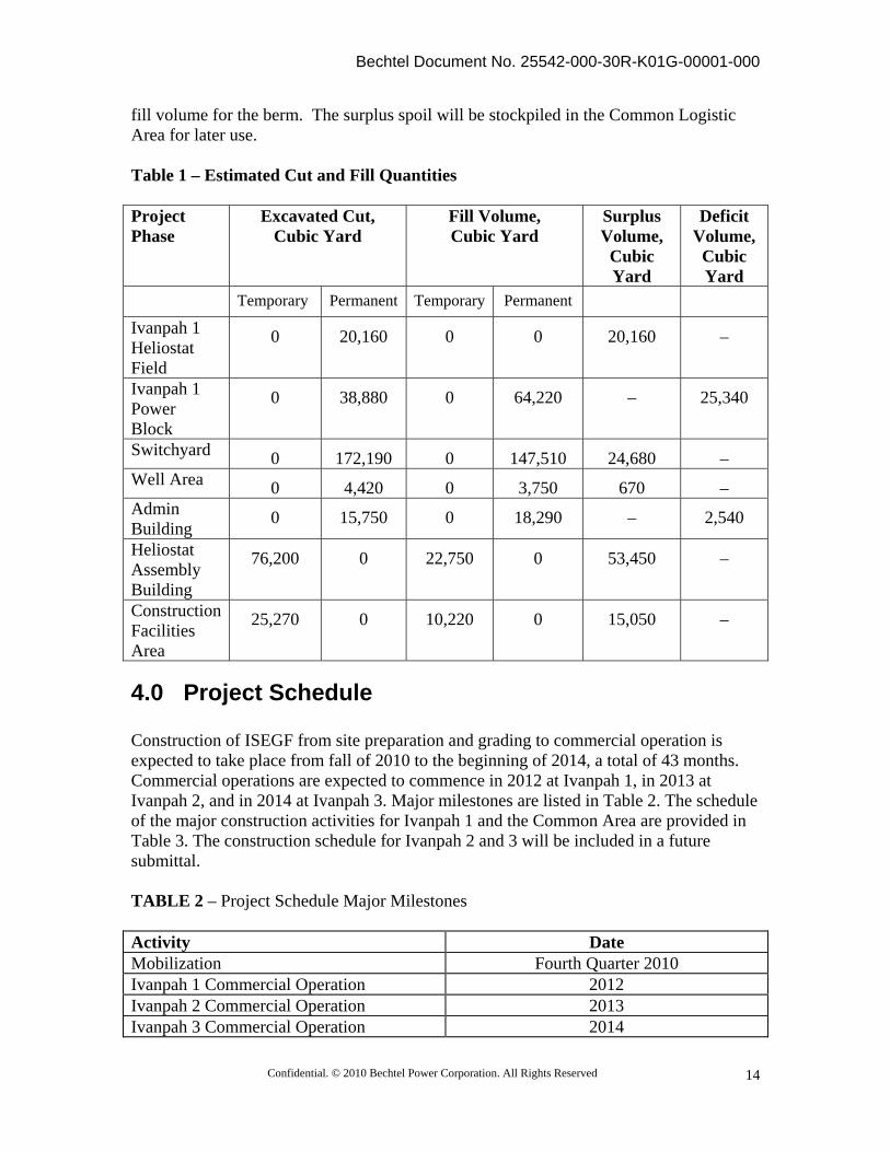
3.4 Volumes of Cut and Fill The grading of the site to design elevations will require cut and fill. Preliminary cut and fill volumes for each project element are shown in Table 1. Trenches excavated for the underground utilities will be entirely refilled. The power block in each unit will require fill to elevate the foundation and to erect the berm. The fill material will use the cut material from the site as much as possible including the surplus cut volume from the heliostat field or roads. The cut volume from the diversion channel can provide sufficient
Bechtel Document No. 25542-000-30R-K01G-00001-000
Confidential. © 2010 Bechtel Power Corporation. All Rights Reserved
14
fill volume for the berm. The surplus spoil will be stockpiled in the Common Logistic Area for later use. Table 1 – Estimated Cut and Fill Quantities Project Phase
Excavated Cut, Cubic Yard
Fill Volume, Cubic Yard
Surplus Volume,
Cubic Yard
Deficit Volume,
Cubic Yard
Temporary Permanent Temporary Permanent
Ivanpah 1 Heliostat Field
0 20,160 0 0 20,160 –
Ivanpah 1 Power Block
0 38,880 0 64,220 –
25,340
Switchyard 0 172,190 0 147,510 24,680 – Well Area 0 4,420 0 3,750 670 – Admin Building
0 15,750 0 18,290 – 2,540
Heliostat Assembly Building
76,200 0 22,750 0 53,450 –
Construction Facilities Area
25,270 0 10,220 0 15,050 –
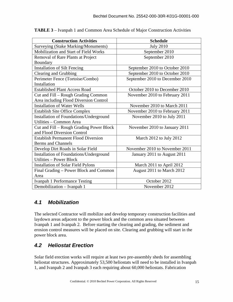
4.0 Project Schedule Construction of ISEGF from site preparation and grading to commercial operation is expected to take place from fall of 2010 to the beginning of 2014, a total of 43 months. Commercial operations are expected to commence in 2012 at Ivanpah 1, in 2013 at Ivanpah 2, and in 2014 at Ivanpah 3. Major milestones are listed in Table 2. The schedule of the major construction activities for Ivanpah 1 and the Common Area are provided in Table 3. The construction schedule for Ivanpah 2 and 3 will be included in a future submittal. TABLE 2 – Project Schedule Major Milestones Activity Date Mobilization Fourth Quarter 2010 Ivanpah 1 Commercial Operation 2012 Ivanpah 2 Commercial Operation 2013 Ivanpah 3 Commercial Operation 2014
Bechtel Document No. 25542-000-30R-K01G-00001-000
Confidential. © 2010 Bechtel Power Corporation. All Rights Reserved
15
TABLE 3 – Ivanpah 1 and Common Area Schedule of Major Construction Activities
Construction Activities Schedule Surveying (Stake Marking/Monuments) July 2010 Mobilization and Start of Field Works September 2010 Removal of Rare Plants at Project Boundary
September 2010
Installation of Silt Fencing September 2010 to October 2010 Clearing and Grubbing September 2010 to October 2010 Perimeter Fence (Tortoise/Combo) Installation
September 2010 to December 2010
Established Plant Access Road October 2010 to December 2010 Cut and Fill – Rough Grading Common Area including Flood Diversion Control
November 2010 to February 2011
Installation of Water Wells November 2010 to March 2011 Establish Site Office Complex November 2010 to February 2011 Installation of Foundations/Underground Utilities – Common Area
November 2010 to July 2011
Cut and Fill – Rough Grading Power Block and Flood Diversion Control
November 2010 to January 2011
Establish Permanent Flood Diversion Berms and Channels
March 2012 to July 2012
Develop Dirt Roads in Solar Field November 2010 to November 2011 Installation of Foundations/Underground Utilities – Power Block
January 2011 to August 2011
Installation of Solar Field Pylons March 2011 to April 2012 Final Grading – Power Block and Common Area
August 2011 to March 2012
Ivanpah 1 Performance Testing October 2012 Demobilization – Ivanpah 1 November 2012
4.1 Mobilization The selected Contractor will mobilize and develop temporary construction facilities and laydown areas adjacent to the power block and the common area situated between Ivanpah 1 and Ivanpah 2. Before starting the clearing and grading, the sediment and erosion control measures will be placed on site. Clearing and grubbing will start in the power block area.
4.2 Heliostat Erection Solar field erection works will require at least two pre-assembly sheds for assembling heliostat structures. Approximately 53,500 heliostats will need to be installed in Ivanpah 1, and Ivanpah 2 and Ivanpah 3 each requiring about 60,000 heliostats. Fabrication
Bechtel Document No. 25542-000-30R-K01G-00001-000
Confidential. © 2010 Bechtel Power Corporation. All Rights Reserved
16
buildings will be used to assemble heliostats during all three construction phases. Once construction of Ivanpah 3 is completed, the buildings will be removed and the area restored.
4.3 Power Block and Towers Concrete, mechanical and electrical works of the power block will be performed over a period of 15 months after the immediate area is brought to its designated grade elevations. The Common Area, located between Ivanpah 1 and 2, will be used for the fabrication sheds and construction parking. It can be used for construction laydown if necessary. However, temporary laydown of materials at each site will generally occur in the vicinity of active construction work.
5.0 Best Management Practices The project has been designed and staged during construction to minimize and confine impacts to only a small area at any given time, thereby limiting the amount of exposed soil. Construction is expected to proceed as expediently and efficiently as possible, thereby ensuring that as little soil is exposed for as short a time as possible. The following sections present standard construction BMPs, most of which are described in the California Storm Water Best Management Practice Handbook (CASQA, 2003a and 2003b) and the Caltrans Construction Stormwater BMPs guidelines in conjunction with the Caltrans 2006 Standard Plans and Specifications. Appendix 4 contains the CASQA Handbook BMP factsheets with detailed descriptions of the BMPs discussed in the following sections. The fact sheets also include the maintenance practices for each BMP. Figures 23 to 25 show the layout and details of the BMPs to be used for the Ivanpah 1 and the Common Area. A subsequent DESCP will be prepared and submitted in a later stage to address the BMPs for the construction and operation of Ivanpah 2 and 3 and other linear features including the natural gas pipeline. The following sections present the recommended construction BMPs for stormwater pollution prevention at the ISEGF construction laydown areas, plant site, and linear facilities. Each section provides information on BMP implementation as it relates to the activity being performed. BMPs that may have an impact on implementation of the DESCP will be reviewed by managers and construction contractors. While performing the work, the contractors may implement additional control measures if necessary to comply with permit requirements.
5.1 General Erosion Control Measures The objective of the erosion control measures is to impact as small an area as possible at any given time, thereby limiting the amount of exposed soil. BMPs will be used to help maintain water quality, protect property from erosion damage, and prevent accelerated soil erosion or dust generation. Temporary erosion control measures would be

Bechtel Document No. 25542-000-30R-K01G-00001-000
Confidential. © 2010 Bechtel Power Corporation. All Rights Reserved
17
implemented before construction begins and they would be evaluated and maintained during construction. These measures typically include physical stabilization, dust suppression, berms, ditches, and sediment barriers. These measures would be removed from the site after the completion of construction. To reduce erosion, project construction will minimize land disturbance by limiting construction activities only to areas that are essential to the installation and operation of the project. Grading is not intended to level the site, but rather to prepare the site for installation and future maintenance of the heliostats. Within the heliostat array fields, vegetation in every 5th row will be cleared with a motorgrader (blade). Scalping the surface vegetation with a motorgrader blade will likely penetrate the upper few inches of the soil surface layer and leave some of the existing root systems intact to anchor the soil at locations where the vegetation was cleared, reducing the potential for erosion. Extensive site grading consisting of cuts and fills will be limited to the power block areas, substation, common administrative area, heliostat assembly building area, major access roads and in heliostat field areas requiring improvements to grade for access. Vegetation removed by blading will be stockpiled for onsite or offsite disposal. Succulent plant species and selected sensitive and rare plant species would be salvaged and transplanted into windrows, and maintained in the nursery area for later transplanting in accordance with the ISEGF Special-Status Plant Avoidance and Protection Plan. Shrubs and other plant species would be revegetated by the collection of seeds, and re-seeding following decommissioning. BLM may also potentially open up the site prior to site grading to invite the public to come in and salvage the accessible vegetation. Disking and light grading may be used prior to compaction by rolling. Disturbed soils will be compacted to reduce the rainfall absorptive capacity and vegetative productivity of the soils that are permanently covered by project facilities. The graded surfaces in the power block and the Administration Building areas will be stabilized by either gravel or riprap. Flood protection berms will be lined with gabion mattress on the upslope side and riprap on the protected side. At the ephemeral crossings, and other areas as needed, the disturbed surfaces will be treated with a polymeric emulsion blend soil binder as required to stabilize slopes. Non-active areas will be stabilized as soon as feasible after construction is complete and no later than 14 days after construction in that portion of the site has temporarily or permanently ceased. It will be necessary to segregate and stockpile surface soils and organic matter during construction and excavation. In areas of substantial grading, native vegetation may be harvested for possible reuse to obtain long term soil stabilization. All excavated soils are to be reused during construction at the site to prevent subsequent erosion and sedimentation issues. Materials suitable for backfill will be stored in stockpiles at designated locations and be protected by the BMP designated for wind and water erosions.
Bechtel Document No. 25542-000-30R-K01G-00001-000
Confidential. © 2010 Bechtel Power Corporation. All Rights Reserved
18
Potable water (groundwater) will be applied to disturbed soil areas of the project site to control dust and maintain optimum moisture levels for compaction as needed. The access roads to individual plants will be paved from their point of connection to Colosseum Road. Colosseum Road, from its intersection with Yates Well Road to the project site, will also be paved. All public roadways (Yates Well Road and Colosseum Road) will be maintained to minimize pollution from dust, dirt and debris caused by construction activities. These streets will be swept at the end of the day if visible soil materials are carried onto them. The following general erosion and sediment control measures may be used during various phases of the project:
Proper scheduling and sequencing of activities (EC-1): Each phase of the project must follow this practice throughout the entire construction period.
Preservation of existing vegetation (EC-2): The existing vegetation, especially the rare species, should be preserve as possible on the site before the mobilization and during the construction period of project for the entire site.
Geotextiles and mats (EC-7): This measure may be applied to the excavated area to protect against rainfall erosion during the construction period. Geotextiles will be applied to the slope of berm at power block and switchyard for long term erosion control.
Earth dikes and drainage swales (EC-9): This measure will be applied to power block and the Common Area for flood protection, but may also be applied during construction for temporary drainage control.
Velocity dissipation devices (EC-10): This control measure will be applied to each diversion channel outlet and drainage outlet at power block and the Common Area. The measure will be used for both temporary and permanent facilities.
Silt fences and fiber rolls (SE-1 and SE-5): Silt fences will be used for sediment control during the construction period. Fiber rolls will be applied as check dams on drainage swales and on cut and fill slopes to control long runs of sheet flows.
Stockpile management (WM-3): This measure will be applied to control the stormwater pollution and dust from stockpiles of construction materials and soils.
5.1.1 Access Road, Entrance and Parking, and Laydown Areas/ Offsite Vehicle Tracking
Controls will be in place to minimize or eliminate soils from being tracked off the project site from vehicles. Primary access to the site is via the Yates Well Road interchange on I-
Bechtel Document No. 25542-000-30R-K01G-00001-000
Confidential. © 2010 Bechtel Power Corporation. All Rights Reserved
19
15, and Colosseum Road to the west of the Primm Valley Golf Club. Colosseum Road will be re-routed between Ivanpah 1 and Ivanpah 2 and paved from its intersection with Yates Well Road to the project site. In addition, the access roads to individual plants will be paved from their point of connection to Colosseum Road. A stabilized entrance/exit and a wheel wash facility will be provided to clean vehicle wheels prior to exiting the construction area. The parking and laydown areas will be stabilized with coarse gravel. All surfaces will be regularly watered to reduce generation of dust, but will not be excessively watered so as to generate runoff. As shown in Figure 23, silt fences or fiber rolls will be used at edges of these areas, as necessary to minimize sediment discharging into swales or ditches. All public roadways (Yates Well Road and Colosseum Road) will be maintained regularly to minimize pollution from dust, dirt and debris caused by construction activities. These streets will be swept at the end of the day if visible soil materials are carried onto them. The following control methods will be considered for offsite vehicle tracking, as necessary.
Stabilized construction entrance/exit (TC-1) Stabilized construction roadway (TC-2) Tire wash (TC-3) Entrance/exit Street sweeping (SE-7) Paving and grinding operations (NS-3)
5.1.2 Dust Suppression and Control During construction of the project and the related linear facilities, dust erosion control measures would be implemented to minimize the wind-blown loss of soil from the site. Potable water (groundwater) will be applied to disturbed soil areas of the project site to control dust and maintain optimum moisture levels for compaction as needed, but will not be excessively watered so as to generate runoff. Dust palliatives such as Soil-Sement or approved equal per SWPPP may be applied to conserve construction water consumption. The following control method will be considered for dust suppression, as necessary:
Wind erosion control (WE-1) Water conservation practices (NS-1)
5.1.3 ISEGF Site and Linear Facilities The power block area for each phase will be graded with moderate slopes to direct runoff to outlets with oil/water separator before overflowing through rip-rap to reinstate natural sheet flow conditions.
Bechtel Document No. 25542-000-30R-K01G-00001-000
Confidential. © 2010 Bechtel Power Corporation. All Rights Reserved
20
Overall the project is being designed to maintain, to the extent possible, the existing sheet flow patterns on the site. Sediment control barriers like silt fence would be placed in locations where offsite drainage could occur to prevent sediment from leaving the site. When used, sediment barriers would be properly installed, then removed after construction. Any soil stockpiles, including sediment barriers around the base of the stockpiles, would be stabilized and covered. Primary access to the site is via the Yates Well Road interchange on I-15, and Colosseum Road to the west of the Primm Valley Golf Club. Colosseum Road will be re-routed between Ivanpah 1 and Ivanpah 2 and paved from its intersection with Yates Well Road to the project site. In addition, the access roads to individual plants will be paved from their point of connection to Colosseum Road. A stabilized entrance/exit and a wheel wash facility will be provided to clean vehicle wheels prior to exiting the construction area. Runoff detention basins and other large-scale sediment traps are not considered necessary due to the low rainfall amount and the low impact development approach for the site.
5.1.4 Site Stabilization and Demobilization As construction nears completion, areas used for temporary parking, storage and laydown will be cleared and stabilized. Areas that will continue to be used for parking or storage will have permanent stormwater collection and conveyance structures provided. Within the heliostat array fields, vegetation every 5th row will be cleared with a motorgrader (blade). Scalping the surface vegetation with a motorgrader blade will penetrate the upper few inches of the soil surface layer and leave some of the existing root systems intact to anchor the soil at locations where the vegetation was cleared, reducing the potential for erosion. Heliostats are relatively small (about 13 feet high each), contain no hazardous materials, and are not essential structures. Their potential structural failure in flood conditions also should not pose a risk to personnel, and the heliostat fields therefore require no special flood protection measures. Onsite water consumption will be minimal—mainly to replace boiler feedwater blowdown and provide deionized water for washing heliostats. The latter is required in a washing cycle of 2 weeks, during which all heliostats are washed, to maintain them at full performance. Because of dust created during site grading, the washing cycle potentially may be more frequent (but not likely more than double) when one plant is operating and another is being graded. This situation would be limited to a 5-month period when Ivanpah 1 is operational as Ivanpah 3 is being graded. Paved access roads will have ditches, culverts and local fords with reinforced concrete shoulders to convey stormwater runoff. Overtopping of the road surface during heavy rain storms and potential washout are to be expected. Routine vehicle traffic during project operation would be limited to existing roads, most of which will be paved or
Bechtel Document No. 25542-000-30R-K01G-00001-000
Confidential. © 2010 Bechtel Power Corporation. All Rights Reserved
21
covered with gravel. Access routes will also be graded between the heliostat arrays to permit bi-weekly washing of the mirrors with a pick-up truck-mounted tanker and the occasional blading of vegetation due to plant re-growth. Standard operating activities would not involve the disruption of soil. When linear facilities need to be inspected or maintained, vehicle traffic near these areas would be minimized.
5.2 Other Controls ISEGF will use hazardous materials during construction, such as vehicle fluids, including oil, grease, petroleum, and coolants, paints, solvents and curing compounds. The project will comply with good engineering practices, applicable laws and regulations for the storage of these materials to minimize the potential for a release of hazardous materials, and will conduct emergency response planning to address public health concerns regarding hazardous materials use and storage.
5.2.1 Material Handling and Storage All construction equipment will be maintained to control leaks and spills, and fueling will only be conducted within contained areas. Any contaminated soils resulting from spills will be dug up as quickly as possible, and then removed from the site for proper disposal. There will be a variety of chemicals stored and used during the construction of ISEGF. All hazardous materials will be handled and stored in accordance with applicable codes and regulations. Hazardous material management during the construction phase is addressed in the Hazardous Material Management Plan - requirement of California Energy Commission Condition HAZ-3. In addition, a Hazardous Materials Business Plan is required by California Code of Regulations Title 19 and the Health and Safety Code (Section 25504). In accordance with these regulations, the Hazardous Materials Business Plan will include an inventory and location map of operational hazardous materials onsite and an emergency response plan for hazardous materials incidents. Specific topics to be covered in the plan include:
Facility identification Emergency contacts Chemical inventory information (for every hazardous material above threshold
limits) Site map Emergency notification data Procedures to control actual or threatened releases Emergency response procedures Training procedures Certification
The Hazardous Materials Business Plan (for operational materials) will be filed with the San Bernardino County Division of Environmental Health (DEH) and updated annually in accordance with applicable regulations. The San Bernardino County DEH will ensure
Bechtel Document No. 25542-000-30R-K01G-00001-000
Confidential. © 2010 Bechtel Power Corporation. All Rights Reserved
22
review by and distribution to other potentially affected agencies including the local fire district. The quantities of hazardous materials that will be onsite during construction will generally be limited to gasoline, diesel fuel, motor oil, hydraulic fluid, solvents, cleaners, sealants, welding flux, various lubricants, paint, and paint thinner. There are no feasible alternatives to vehicle fuels and oils for operating construction equipment. The types of paint required are dictated by the types of equipment and structures that must be coated and by the manufacturers’ requirements for coating. The following BMPs will be considered for material handling and storage:
Vehicle and equipment cleaning (NS-8) Vehicle and equipment refueling (NS-9) Vehicle and equipment maintenance (NS-10) Material delivery and storage (WM-1) Material use (WM-2) Spill prevention and control (WM-4)
5.2.2 Foundations During construction of the foundations, a concrete washout area will be required. The concrete washout area will be located near the main entrance to the Ivanpah project site, and will be at least 50 feet away from major drainages (Figure 23). Dumping of excess concrete and washing out of delivery vehicles will be prohibited at other locations onsite. Notices will be posted to inform all drivers. The following BMPs will be considered during the construction of foundations:
Concrete waste management (WM-8) Concrete curing (NS-12)
5.2.3 Solid and Hazardous Waste Management A Construction Waste Management Plan has been developed in response to Condition of Certification WASTE-3. This plan addresses the onsite storage, handling and management of all solid wastes generated at the Project site during construction and start-up including non-hazardous, hazardous, and sanitary wastes including special wastes destined for recycling (e.g., used oil, used oil filters, used welding rods, scrap metal). As defined in the EPC Contract, the Owner, Solar Partners I, II, IV, and VIII and the parent company BrightSource Energy, Inc. (BSE), will retain responsibility for any existing wastes above or below ground at the project site, as well as any wastes generated as part of operational activities after care, custody and control of the Project have been transferred to the Owner. It also describes the specific responsibilities of Bechtel and its subcontractors.
Bechtel Document No. 25542-000-30R-K01G-00001-000
Confidential. © 2010 Bechtel Power Corporation. All Rights Reserved
23
This plan does not address construction waste management for any of the offsite linear facilities constructed as part of the overall development (e.g., power transmission line), nor does it address waste management issues related to the operational phase of the Project. The types of waste that are expected to be generated during the course of construction are described below.
5.2.3.1 Nonhazardous Solid Waste
Listed below are nonhazardous wastes that could potentially be generated from construction activities. Paper, Wood, Glass, and Plastics. Paper, wood, glass, and plastics will be generated from packing materials, waste lumber, insulation, and empty nonhazardous chemical containers during project construction. These wastes will be recycled where practical. Waste that cannot be recycled will be disposed of weekly in a Class III landfill. Onsite, the waste will be placed in dumpsters. Concrete. Waste concrete will be disposed of in a Class III landfill or at clean fill sites, if available or will be recycled and disposed of at a construction and demolition site. As discussed in Section 5.2.2, an onsite concrete washout area is located near the main entrance to the site. Concrete washout facility will be maintained to provide adequate holding capacity with a minimum freeboard of 12 inches (for below grade type). Hardened concrete will be removed and disposed following Caltrans standard Specification Section 7-1.13 or 15-3.02. The Concrete Waste Management (WM-8) BMP will be imposed to prevent pollutant from waste concrete. Metal. Waste metal, including steel from welding/cutting operations, packing materials, and empty nonhazardous chemical containers, and aluminum waste from packing materials and electrical wiring will be recycled where practical and nonrecyclable waste will be deposited in a Class III landfill.
5.2.3.2 Wastewater
Wastewater generated during construction will include stormwater runoff, pressure testing water, and equipment washdown water. Depending on the chemical quality of these wastewaters, they could be classified as hazardous or nonhazardous. The waste waters would be sampled and if they are hazardous would be disposed of in accordance with applicable regulations. The pressure testing water will result from the gas pipeline test after the installation as described in Section 3.1.1. After hydrostatic testing, the test water will be chemically analyzed for contaminants before reuse or disposal. The water will be used for dust control unless the analysis shows that the water is contaminated, in which case the water would be trucked to an appropriate disposal facility. Temporary approvals for test water
Bechtel Document No. 25542-000-30R-K01G-00001-000
Confidential. © 2010 Bechtel Power Corporation. All Rights Reserved
24
use and permits for discharge will be obtained by the construction Contractor, as required.
5.2.3.3 Hazardous Waste
Most of the hazardous waste generated during construction will consist of liquid waste, such as water from flushing and cleaning fluids, passivating fluid (to prepare pipes for use), and solvents. Some hazardous solid waste, such as welding materials, batteries, and dried paint, may also be generated. Flushing and cleaning waste liquid will be generated as pipes are cleaned and flushed. The volume of flushing and cleaning liquid waste generated is estimated to be one to two times the internal volume of the pipes cleaned. The quantity of welding, solvent, batteries, and paint waste is expected to be minimal. Wastewaters generated during construction could also be considered hazardous, if demonstrated so by sampling. The construction contractor will be considered the generator of hazardous construction waste and will be responsible for proper handling of hazardous waste in compliance with all applicable federal, California and San Bernardino County and regulations. This responsibility will include licensing, personnel training, accumulation limits and times, and reporting and recordkeeping. The hazardous waste will be collected in satellite accumulation containers near the points of generation. It will be moved daily to the contractor’s 90-day hazardous waste storage area located at the site construction laydown area. The waste will be removed from the site by a certified hazardous waste collection company and delivered to an authorized hazardous waste management facility, before expiration of the 90-day storage limit. The following BMPs will be considered at the designated storage locations:
Cover or store hazardous materials indoors, if possible (WM-1) Material delivery and storage (WM-1) Material use (WM-2) Stockpile management (WM-3) Spill prevention and control (WM-4) Solid waste management (WM-5) Hazardous waste management (WM-6) Sanitary/Septic Waste Management (WM-9) Liquid Waste Management (WM-10)
5.2.4 Potential Contaminated Soil
The project area is characterized by a desert scrub community dominated by creosote bush (Larrea tridentata) and white bursage (Ambrosia dumosa). The ground surface is primarily comprised of coalesced and dissected alluvial fans and desert washes. It is unlikely that, with exception of light cattle grazing, there has been any other historical
Bechtel Document No. 25542-000-30R-K01G-00001-000
Confidential. © 2010 Bechtel Power Corporation. All Rights Reserved
25
use of the site. Soils in the area are not expected to be contaminated. No existing site features have, as a result of past usage, contributed pollutants to stormwater (e.g., toxic materials that have been treated, stored, disposed of, spilled, or leaked onto the construction site). As such, it is unlikely that contaminated soil will be encountered during construction. However, operators and construction personnel will be asked to report unusual conditions to the appropriate personnel and the area and/or material will be properly contained during investigative actions. As described earlier, the Owner will be responsible for management of pre-existing site contamination including contaminated soils. If soils (contaminated by construction activities) require temporary stockpiling, piles will be placed on and covered with plastic sheeting or tarps that are secured safely with sand bags and bermed with fiber rolls or silt fencing to prevent runoff from leaving the area. If required, samples will be collected and sent to a certified analytical laboratory for characterization. If contamination is detected, the waste will be handled and properly disposed of in an authorized waste management facility. The following BMP will be considered:
Contaminated Soil Management (WM-7)
5.2.5 Groundwater/Dewatering Controls It is unlikely that groundwater will require removal during the construction phase of ISTEGF because the groundwater table is expected to be located substantially below the maximum excavation depth. There is no need of dewatering for the stormwater on the site. But dewatering may be needed for non-stormwater during the construction. The collected non-stormwater will be handled and properly disposed of in a manner consistent with federal, state, and local regulations. The following control methods will be considered for groundwater/dewatering controls, as necessary:
Dewatering operations (NS-2)
6.0 References
1. California Stormwater Quality Association (2003a). California Stormwater Best Management Practices Handbook – New Development and Redevelopment.
2. California Stormwater Quality Association (2003b). California Stormwater Best
Management Practices Handbook – Industrial and Commercial.
Bechtel Document No. 25542-000-30R-K01G-00001-000
Confidential. © 2010 Bechtel Power Corporation. All Rights Reserved
26
3. California Department of Water Resources (DWR), 2004. California’s Groundwater – Bulletin 118. Basin Descriptions: Ivanpah Valley Groundwater Basin. http://www.groundwater.water.ca.gov/bulletin118/basin_desc/basins_s.cfm
4. U. S. Department of Commerce, National Oceanic and Atmospheric
Administration, National Weather Service, Hydrometeorological Study Center, Precipitation Frequency Data Server (PFDS), Silver Spring, MD 2006. Website: (Accessed 2/22/2010)
http://hdsc.nws.noaa.gov/hdsc/pfds/sa/sca_pfds.html
5. California State Water Resources Control Board (2009). National Pollutant Discharge Elimination System (NPDES) General Permit for Storm Water Discharges Associated with Construction and Land Disturbance Activities. Order No. 2009-0009-DWQ, NPDES NO. CAS000002.
6. Converse Consultants (2009). Geotechnical Study, Ivanpah Solar Electric
Generatign System, San Bernardino County, California. Prepared for BrightSource Energy. Converse Project No. 08-33231-01, dated October 16, 2009.
7.0 Appendices

Bechtel Document No. 25542-000-30R-K01G-00001-000
Confidential. © 2010 Bechtel Power Corporation. All Rights Reserved
27
Appendix 1
Figures
Bechtel Document No. 25542-000-30R-K01G-00001-000
Confidential. © 2010 Bechtel Power Corporation. All Rights Reserved
28
Appendix 2
Calculations & Memorandum
1. Technical Memorandum #16: Stormwater Design Flow for Ivanpah 1 and Common Area, dated April 13, 2010, prepared by West Yost Associates
2. Technical Memorandum #18: Stormwater runoff and sediment transport, Ivanpah Valley, California, dated April 13, 2010, prepared by West Yost Associates
3. Ivanpah 1 Power Block and Common Area Diversion Channels Hydraulic Design Calculation, Rev 0, prepared by Bechtel Power Corporation
4. Ivanpah 1 Power Block and Administration Building Drainage Sizing Calculation, Rev 0, prepared by Bechtel Power Corporation

Bechtel Document No. 25542-000-30R-K01G-00001-000
Confidential. © 2010 Bechtel Power Corporation. All Rights Reserved
29
Appendix 3
BMP Fact Sheets (References 1&2)

Bechtel Document No. 25542-000-30R-K01G-00001-000
Confidential. © 2010 Bechtel Power Corporation. All Rights Reserved
30
Appendix 4
Technical Specification for Earthwork, Grading, Filling, and Backfilling
(including trenching and backfilling)
25542-000-3PS-CE01-00001-002
Bechtel Document No. 25542-000-30R-K01G-00001-000
Confidential. © 2010 Bechtel Power Corporation. All Rights Reserved
31
Appendix 5
Copies of recommendations from the County of San Bernardino, California, Department of Fish and Game, and
Lahontan Regional Water Quality Control Board
Bechtel Document No. 25542-000-30R-K01G-00001-000
Confidential. © 2010 Bechtel Power Corporation. All Rights Reserved
32
Appendix 6
Risk Level Determination in accordance with Appendix 1 of the California Construction General Permit Order 2009-0009-
DWQ adopted on September 2, 2009
Bechtel Document No. 25542-000-30R-K01G-00001-000
Confidential. © 2010 Bechtel Power Corporation. All Rights Reserved
33
The risk of accelerated erosion and sedimentation from wind and water depends on a number of factors, including proximity to receiving water bodies, climate, topography, and soil type. Construction General Permit Order 2009-0009-DWQ requires dischargers to assess the risk level of a site based on both sediment transport and receiving water risk. Risk levels are established by determining two factors: first, the site's sediment risk; and second, receiving water risk during periods of soil exposure (i.e., grading and site stabilization). Both factors are used to determine the combined site-specific Risk Level. The risk level of the ISEGF project is determined using of the Risk Determination Worksheet contained in Appendix 1 of the 2009 Construction General Permit Order. Step 1: Determine Sediment Risk via Option 1 (GIS Map Method - EPA Rainfall Erosivity Calculator & GIS map) For the GIS method, the Rainfall Erosivity Factor (R) for Ivanpah 1, 2 and 3 is determined to be 33.34, with the aid of the EPA online Erosivity Index Calculator (accessed at web link http://cfpub.epa.gov/npdes/stormwater/LEW/lewCalculator.cfm) as shown in the following page. The start date of earth disturbance of September 15, 2010 is based on schedule start of the earthwork activities for Ivanpah 1. The end date of December 31, 2013 for final site stabilization is conservatively tied to the start of commercial operation for Ivanpah 3. The latitude and longitude of the solar tower for Ivanpah 2 is used to represent the facility location. The product of K (soil erodibility factor) and LS (hillslope length and gradient factors) for the Ivanpah site is estimated to be 0.4 from the GIS map published by the State Regional Water Quality Control Board as shown in figure below. The watershed erosion estimate or soil loss can be determined by multiplying the R factor and the product of K and LS factors and is equal to 13.3 tons per acre. The site Sediment Risk factor is determined to be LOW because the estimated soil loss is less than 15 tons per acre.
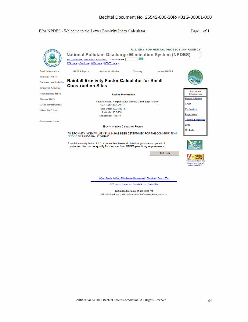
Bechtel Document No. 25542-000-30R-K01G-00001-000
Confidential. © 2010 Bechtel Power Corporation. All Rights Reserved
34
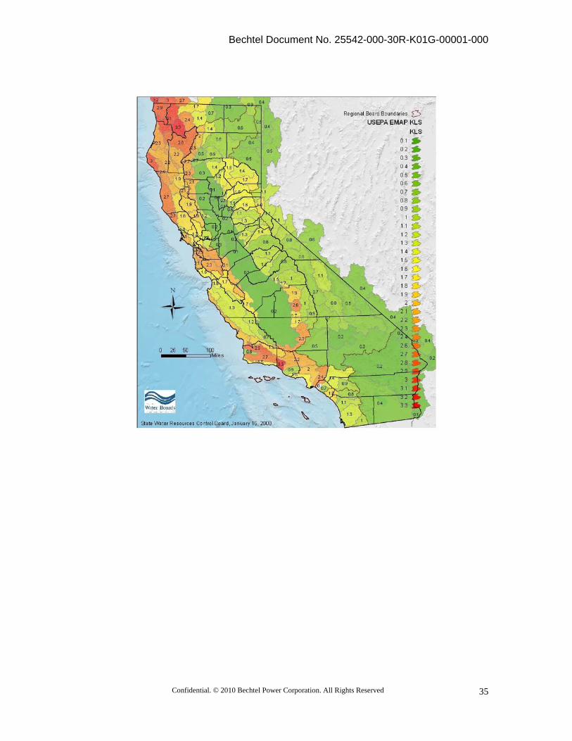
Bechtel Document No. 25542-000-30R-K01G-00001-000
Confidential. © 2010 Bechtel Power Corporation. All Rights Reserved
35
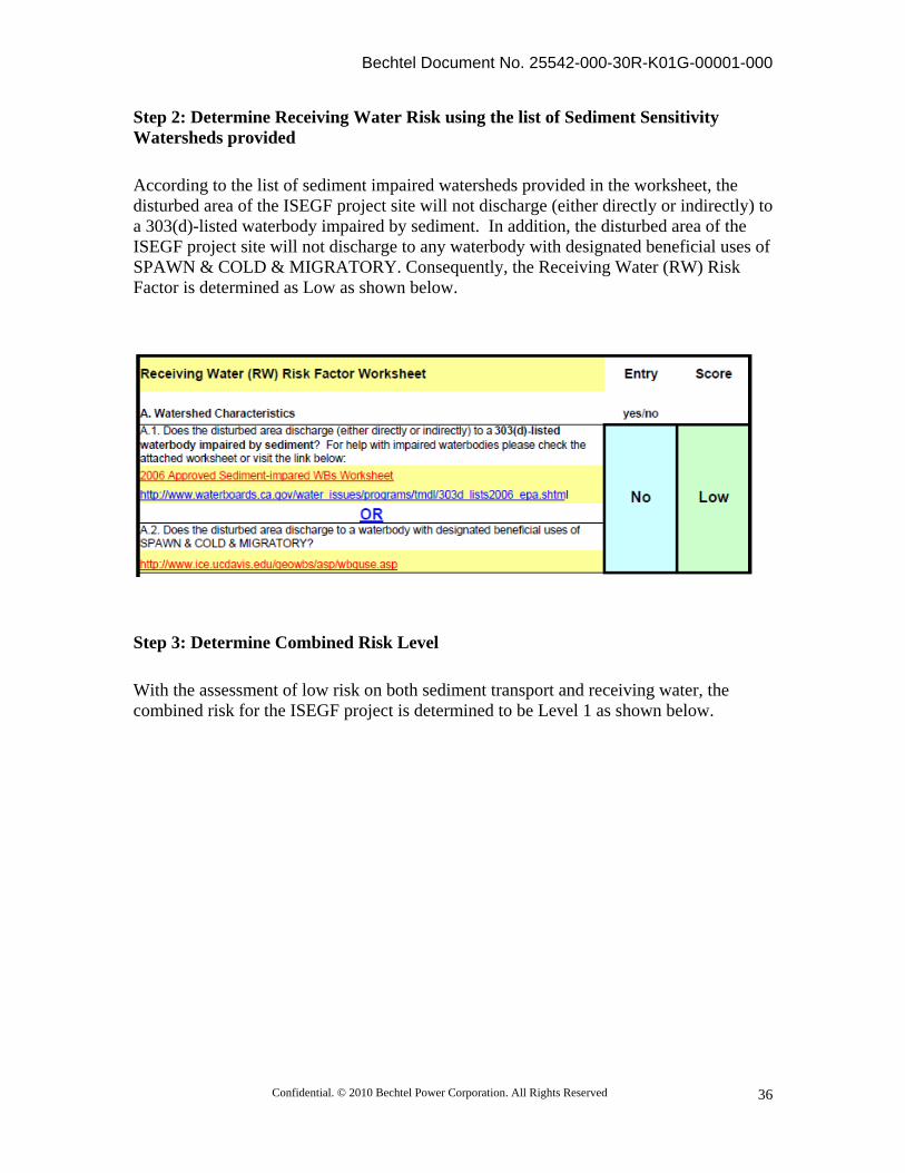
Bechtel Document No. 25542-000-30R-K01G-00001-000
Confidential. © 2010 Bechtel Power Corporation. All Rights Reserved
36
Step 2: Determine Receiving Water Risk using the list of Sediment Sensitivity Watersheds provided
According to the list of sediment impaired watersheds provided in the worksheet, the disturbed area of the ISEGF project site will not discharge (either directly or indirectly) to a 303(d)-listed waterbody impaired by sediment. In addition, the disturbed area of the ISEGF project site will not discharge to any waterbody with designated beneficial uses of SPAWN & COLD & MIGRATORY. Consequently, the Receiving Water (RW) Risk Factor is determined as Low as shown below.
Step 3: Determine Combined Risk Level
With the assessment of low risk on both sediment transport and receiving water, the combined risk for the ISEGF project is determined to be Level 1 as shown below.
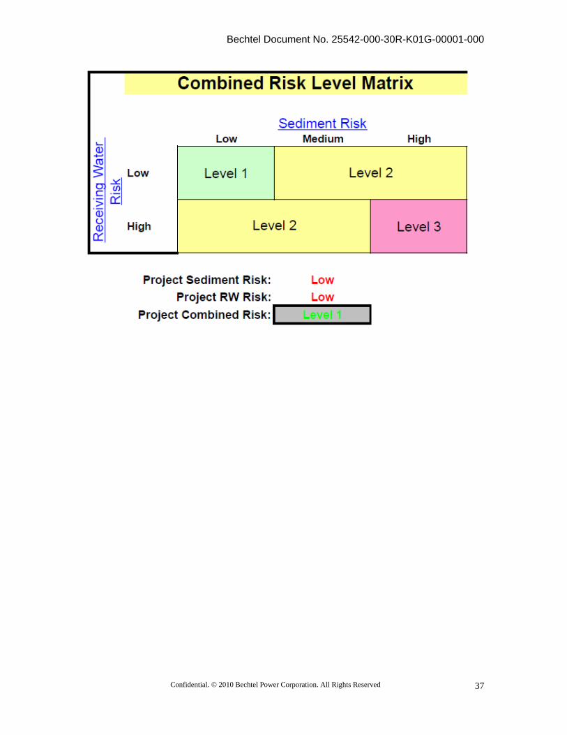
Bechtel Document No. 25542-000-30R-K01G-00001-000
Confidential. © 2010 Bechtel Power Corporation. All Rights Reserved
37