iter, the decisive step towards fusion energy (vorgetragen
TRANSCRIPT

29
ITER, the Decisive Step towards Fusion Energy (vorgetragen von G. Janeschitz)
G. Janeschitz, ITER Organisation, 13067 St Paul Lez Durance, France
1. Introduction:
Fusion is a very promising future energy option, which is characterized by almost unlimited fuel reserves, favourable safety features and environmental sustainability. The aim of the worldwide fusion research is a fusion power station which imitates the process taking place in the sun and thus gains energy from the fusion of light atomic nuclei. However, the reaction used on earth is different from the one taking place inside the sun and other stars [1]. The energy gain of fusion is the result of different binding energies of the elementary particles (protons and neutrons) in the nucleus of the different elements in the periodic system (Fig. 1). When light elements like Hydrogen isotopes fuse to Helium a net energy gain results, i.e. the difference in binding energy is released in form of kinetic energy of the resulting nuclear particles.
In order to overcome the repelling force between the charged atomic nuclei, tremendous kinetic energies would be required (equivalent of billions (thousands of millions) of degrees) if the tunnel effect would not exist. Due to the quantum mechanical tunnel effect there is a probability of fusion processes to occur even at much lower temperatures. However, due to the high Coulomb scattering rate many collisions are needed to make one fusion process, the number of collisions needed depending on temperature. However, at very high temperature the collision cross section decreases and thus there
exists an optimum temperature for each fusion process (Fig. 2). While in the core of the sun protons fuse to helium at 15 million degrees and 100 billions atmospheres, on earth, with pressures of some 100 atmospheres, in the order of 100 million degrees are required. These temperatures correspond to ~ 10 keV average particle energy in a Maxwellian distribution [1].
The fusion reactions which are achievable on earth with a possible net energy output can be seen in Fig. 2. It is evident that the reaction with the highest probability and with the lowest required temperature (kinetic energy) is the Deuterium (one proton + one neutron) –
Fig. 1: Binding energy versus atomic mass.
One can see the large gain in binding energy between Hydrogen and He.
Fig. 2: Relative fusion power density versus plasma temperature in million degrees. It can be seen that the D-T reaction is the most promising fusion reaction to be achieved on earth.

30
Tritium (one proton + two neutrons) to He4 (two protons + two neutrons) + one neutron reaction. The energy of 17.5 MeV per fusion process in this reaction is distributed between the neutron and the He nucleus as 4/5 (14 MeV) and 1/5 (3.5 MeV), respectively. Thus the neutrons carry 4/5 of the reaction’s energy. They transport it to a ~ 500 mm thick structure surrounding the burn chamber which is called the blanket, where by collisions with nuclei of the blanket material they release their energy resulting in a volumetric heat production there.
One of the partners in the D-T reaction, namely Tritium, is a radioactive element with a half-lifetime of ~12 years and thus does not exist naturally on earth in sufficient quantity. Therefore Tritium has to be produced by a nuclear reaction between neutrons from the fusion reaction and Lithium contained in the blanket, resulting in He4 and Tritium.
How can a 100 Million degree hot gas called a “plasma” be confined in such a way as to isolate it from the vessel wall? At these temperatures atoms are split into their parts, namely electrons and ions and thus a plasma forms. A plasma is the fourth state of matter consisting of negatively charged electrons (-) and positively charged nuclei (+), also called ions. This makes it possible to confine the plasma in a magnetic field (see Fig. 3). The field lines must have a helical structure in order to confine the plasma. The reason is that in a torus the magnetic field is decaying from smaller radius to the larger radius of the torus and therefore drifts exists for ions and electrons which cause separation of the two families of charged particles and thus an electric field is produced which would cause a force radially out of the torus. A helical magnetic field averages the drifts out. Nevertheless due to the pressure the plasma wants to expand and has to be hold in place by a magnetic well. Therefore for magnetic confinement in a closed torus one needs a helical field structure and a magnetic well [1].
There are two successful ways of producing helical magnetic field structures to confine a hot plasma:
the stellarator, where complex shaped coils produce a helical field with a magnetic well. Different stellarator configurations exist, of which some are very promising, but the development is not yet enough advanced to build a reactor class machine like ITER
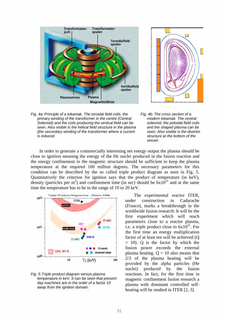
In the tokamak a toroidal magnetic field is generated by the toroidal coils, and the plasma current (in the Mega Ampére range), induced by a transformer in the centre of the torus, generates a “poloidal” magnetic field i.e. concentric to thetoroidal direction of the plasma current. The superposition of these two magnetic fields generates the desired helical field structure. An additional vertical field produced by so-called poloidal field coils (the brown ring coils in Fig. 4) provides the magnetic well and keeps the plasma in the desired position (Fig. 4):
Fig. 3: A hot plasma in a cylinder with and without
magnetic field. A magnetic field confines the plasma to the field lines and thus isolates it from the cylinder walls
.
31
Fig. 4a: Principle of a tokamak. The toroidal field coils, the primary winding of the transformer in the centre (Central Solenoid) and the coils producing the vertical field can be seen. Also visible is the helical field structure in the plasma (the secondary winding of the transformer where a current is induced.
Fig. 4b: The cross section of a modern tokamak. The central soleonid, the poloidal field coils and the shaped plasma can be seen. Also visible is the divertor structure at the bottom of the vessel.
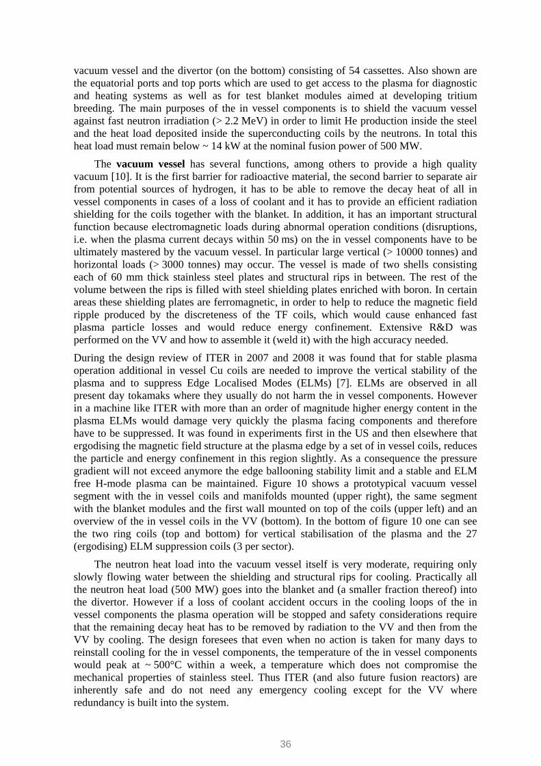
In order to generate a commercially interesting net energy output the plasma should be close to ignition meaning the energy of the He nuclei produced in the fusion reaction and the energy confinement in the magnetic structure should be sufficient to keep the plasma temperature at the required 100 million degrees. The necessary parameters for this condition can be described by the so called triple product diagram as seen in Fig. 5. Quantitatively the criterion for ignition says that the product of temperature (in keV), density (particles per m3) and confinement time (in sec) should be 6x10²¹ and at the same time the temperature has to be in the range of 10 to 20 keV.
The experimental reactor ITER, under construction in Cadarache (France), marks a breakthrough in the worldwide fusion research: It will be the first experiment which will reach parameters close to a reactor plasma, i.e. a triple product close to 6x10²¹. For the first time an energy multiplication factor of at least ten will be achieved (Q = 10). Q is the factor by which the fusion power exceeds the external plasma heating. Q = 10 also means that 2/3 of the plasma heating will be provided by the alpha particles (He nuclei) produced by the fusion reactions. In fact, for the first time in magnetic confinement fusion research a plasma with dominant controlled self-heating will be studied in ITER [2, 3].
Fig. 5: Triple product diagram versus plasma temperature in keV. It can be seen that present day machines are in the order of a factor 10 away from the ignition domain.

32
In order to achieve these parameters and the desired fusion performance requires several ingredients. Beside the fusion reactor physics of a burning plasma, reactor relevant technologies are needed as well (e.g. superconducting coils, actively cooled blanket and divertor, remote maintenance, a Tritium processing plant, etc). Due to the large financial and technical challenges it was decided already in the 1980s to establish an international collaboration and to build only one single experiment worldwide which should push the fusion parameters to the reactor scale. Partners in this project are today the European Union, China, India, Japan, the Russian Federation, South Korea, and the USA . The ITER facility is supposed to demonstrate a long burning, reactor-typical plasma and to test techniques such as plasma heating, plasma confinement by superconducting magnets, as well as energy production, the fuel cycle with tritium breeding and remote handling technologies [4].
2. ITER Physics Basis and ITER Physics Goals:
The ITER design is based on relatively conservative physics requirements in order to ensure that the predicted performance in the new regime of inductive operation at Q = 10 will be surely achieved (Fig 6) [2, 3, 5, 6]. During a design review in 2007 a comprehensive examination of new physics findings was undertaken which resulted in proposals for design improvements [7]. For any next step machine like ITER the achievement of Q = 10 is essential because only at sufficient high Q valules α particle heating dominates. A performance below Q = 10 would thus not allow to examine the behaviour of a reactor plasma. Besides the inductive performance (plasma current driven by the transformer, i.e. pulse length limited to 400 sec) ITER should also demonstrate stationary discharges at Q = 5, i.e. discharges with non-inductively driven current. In these discharges, which are called “Advanced Tokamak Discharges”, the plasma current consists of ~ 60 to 70% bootstrap current (generated by trapped particles in a pressure gradients i.e. driven by the plasma itself) and a smaller part of the current (~ 30 to 40%), driven by external sources, i.e. inductive and non-inductive current drive systems. External current drive is very expensive because the current drive efficiency of the known systems is rather low (< 0.03 MA/MW) i.e. the majority of the applied power is dissipated by plasma heating or even inside the current drive system itself. Therefore, the ongoing plasma physics development aims at increasing the bootstrap current fraction as well as energy confinement. This has shown significant success during the last
Fig.6 : Predicted ITER operational space depicted in a
plane of normalised density (expressing the peaking of the density profile) vs additional heating power in MW (axis pointing downwards)) using an integrated plasma model [6] for inductive discharges. One can see that ITER will most likely exceed Q = 10 in a large part of its operational space.(colour shading – blue to red – and labeled thin black lines show alpha heating power, coloured lines: orange – Q=5, red – H-mode transition, blue – edge density limit, Lila – low temperature limit, green – additional power limit)

33
years by shaping the current distribution inside the plasma towards a radially flat or even a hollow profile in the plasma core region via external current drive aligned with the bootstrap Current. Thereby improved energy and particle confinement can be achieved. This higher confinement in turn yields an increase of the internal pressure gradient, resulting in higher bootstrap currents and thus more self-driven current. The downside of these type of discharges is that the total pressure in the plasma and thus its energy content is lower than in a (peaked) standard current density profile. The other downside is that in order to recover as much as possible of the total pressure these discharges are operated close to, or beyond, classical stability boundaries and need active stabilisation control (e.g, Resistive Wall Mode control)..
The physics goals of ITER are to demonstrate that the above regimes can be produced in a largely self-heated reactor relevant plasma (by alpha particle heating) and thus to provide the required performance to warrant the construction of a future DEMO reactor which should demonstrate the economic viability of fusion.
3. ITER Design and Technology:
The realisation of ITER required the development of several new technologies (e.g. superconducting coils with the relevant field and current density, high heat flux components, remote maintenance, etc.). Therefore seven large R&D projects were performed in full or representative model size (CS- and TF-magnets, Vacuum Vessel, Blanket, Divertor, Remote Maintenance for Blanket and Divertor) accompanied by a large
number of related preparatory and small-scale R&D projects as well as R&D for other large components and systems, e.g. for the fuel cycle. This R&D program provided the basis for the validation of the ITER design and demonstrated that a machine like ITER can be constructed together with industry [4, 8].
Feeders (31)(NbTi)
Correction Coils (18)(NbTi)
Central Solenoid (6)(Nb3Sn)
Divertor (54 cassettes)
Blanket (440 modules)
Cryostat (29 m high x 28 m dia.)
Vacuum Vessel (9 sectors)
Thermal Shield (4 sub-assemblies)
In-Vessel Coils(2-VS & 27-ELM)
Feeders (31)(NbTi)
Correction Coils (18)(NbTi)
Central Solenoid (6)(Nb3Sn)
Divertor (54 cassettes)
Blanket (440 modules)
Cryostat (29 m high x 28 m dia.)
Vacuum Vessel (9 sectors)
Thermal Shield (4 sub-assemblies)
In-Vessel Coils(2-VS & 27-ELM)
Fig. 7: A cut through the ITER machine and the cryostat, all the main components are labeled in the figure.[8]

34
In this paper only the design of the tokamak itself and the major components are presented while items like the buildings and the more standard technology of the balance of plant (e.g. heat transfer systems, cryo plants, etc) are not included. Figure 7 depicts a cut through the ITER machine inside the cryostat which during operation will be under vacuum. A geometrically complex thermal shield protects all superconducting magnets (which are at a temperature of 4.5K) against thermal radiation input.
The cryostat itself consists of a cylindrical vessel with toroidal and poloidal ribs and of a dome-shaped lid capable of coping with the atmospheric pressure of 0.1 MPA. The cryostat floor is supported by the foundations of the ITER building. The cryostat will be kept normally under high vacuum and is thus only vented if repairs on systems inside the cryostat are required. The high vacuum which is initially generated by large pumps is then maintained and further improved by the very large cryo pumping effect of the cooled magnets which are at 4.5K. Leaks into the cryostat must be avoided, because they would cause ice to form on the magnets and on the thermal shields. After a short while this ice would cause the heat input into the coils to grow and thus stop operation. Leak tightness is an issue since there are ~250 penetrations into the cryostat such as for magnet feeders, water cooling pipes for the blanket, the divertor and the plasma burn chamber (called Vacuum Vessel, VV) as well as electrical and diagnostic services. Also rails to support semi-remote maintenance tools for the maintenance of the PF coils and the magnet feeders as well as to re- tighten the pre-compression rings on the TF magnets and the pre-compression structure on the Central Solenoid are mounted on the lid as well as on the side walls of the cryostat.
The magnets are shielded from thermal irradiation from the VV and the cryostat by a thermal shield (green structure in figure 6). The thermal shield consists of a self-supporting grid like stainless steel structure and plates which are cooled by 80 K He gas pumped through small pipes welded onto those plates. All the feeders for the superconducting magnets and many water cooling pipes for the VV penetrate the thermal shield. In addition, due to its complex geometry and requirements to gain access for maintaining the coils it is a high tech component difficult to design. The cryostat and the thermal shield will be passed over to India and Korea, respectively, for the detailed design and manufacturing by autumn 2010.
The magnet assembly which is located between its inner and outer thermal shields is the backbone of the ITER machine. Figure 8 shows the magnet assembly. It consists of the toroidal field magnets [8, 9] with its massive inter coil structures which provide the mechanical rigidity of the machine, the poloidal field magnets needed for producing a magnetic well as well as for plasma shaping and plasma position control, the central solenoid required to initiate and sustain the current in the plasma and finally three sets of 6 correction coils which will provide error field correction. Error fields are generated by misalignment (in the mm range) of TF and PF coils as well as by magnet feeders. In a tokamak like ITER these error fields need to be reduced to 10-5 of the TF field in order to operate effectively.
Fig. 8: The magnet assembly of ITER (CS, TF, PF coils). The magnets also provide the mechanical structure of the device onto which everything else is mounted with the exception of the cryostat.

35
Because of magnetic field strengths of 13 Tesla at the conductor and 5.5 Tesla at the center of the plasma, both types of magnets (CS and TF) have to withstand very large forces on their superconducting cables and on the whole magnet body requiring special design measures. As an example, a radial force of 35000 tonnes exerted onto each TF magnet, when the full field is switched on, has to be withstood by the coil housings through a system of wedge and shear keys. Also on the CS coil vertical and separation forces in the range of 18000 tonnes are possible and have to be accommodated by the structural design. The design of the magnets itself, of the structure and the precise assembly of these large and heavy components (one TF coil weighs 380 tonnes) are one of the challenges of ITER. The development of magnets capable to produce a field of 5.5 T in the centre of the plasma was a difficult task in the 1990s. The development of suitable superconducting cables and of the coils themselves took more than a decade. Also today the manufacturing of these high tech components are demanding for the ITER team, the Domestic Agencies as well as for the industry involved.
Inside the TF coils and the inner thermal shield there are the vacuum vessel and the “in vessel” components (blanket, port plugs and divertor). Figure 9 shows the vessel-in vessel assembly with the blanket modules (450 modules, ~ 4.5 tonnes each) mounted on the
Fig. 9: The vacuum vessel and the in vessel components (blanket and divertor). The blanket modules are mounted on the vacuum vessel and are supplied by water manifolds also mounted on the vacuum vessel (see also fig. 18). Also shown are the equatorial and top port plugs for diagnostic and heating system access.
Fig. 10: Shown are in the upper left a sector of the VV with vertical stability coils (VS-Coils), ELM coils and blanket manifolds mounted, on the upper right the same sector with the blanket modules mounted on top of the VS and ELM coils and at the bottom an overview of all in vessel coils (VS and ELM)
36
vacuum vessel and the divertor (on the bottom) consisting of 54 cassettes. Also shown are the equatorial ports and top ports which are used to get access to the plasma for diagnostic and heating systems as well as for test blanket modules aimed at developing tritium breeding. The main purposes of the in vessel components is to shield the vacuum vessel against fast neutron irradiation (> 2.2 MeV) in order to limit He production inside the steel and the heat load deposited inside the superconducting coils by the neutrons. In total this heat load must remain below ~ 14 kW at the nominal fusion power of 500 MW.
The vacuum vessel has several functions, among others to provide a high quality vacuum [10]. It is the first barrier for radioactive material, the second barrier to separate air from potential sources of hydrogen, it has to be able to remove the decay heat of all in vessel components in cases of a loss of coolant and it has to provide an efficient radiation shielding for the coils together with the blanket. In addition, it has an important structural function because electromagnetic loads during abnormal operation conditions (disruptions, i.e. when the plasma current decays within 50 ms) on the in vessel components have to be ultimately mastered by the vacuum vessel. In particular large vertical (> 10000 tonnes) and horizontal loads (> 3000 tonnes) may occur. The vessel is made of two shells consisting each of 60 mm thick stainless steel plates and structural rips in between. The rest of the volume between the rips is filled with steel shielding plates enriched with boron. In certain areas these shielding plates are ferromagnetic, in order to help to reduce the magnetic field ripple produced by the discreteness of the TF coils, which would cause enhanced fast plasma particle losses and would reduce energy confinement. Extensive R&D was performed on the VV and how to assemble it (weld it) with the high accuracy needed.
During the design review of ITER in 2007 and 2008 it was found that for stable plasma operation additional in vessel Cu coils are needed to improve the vertical stability of the plasma and to suppress Edge Localised Modes (ELMs) [7]. ELMs are observed in all present day tokamaks where they usually do not harm the in vessel components. However in a machine like ITER with more than an order of magnitude higher energy content in the plasma ELMs would damage very quickly the plasma facing components and therefore have to be suppressed. It was found in experiments first in the US and then elsewhere that ergodising the magnetic field structure at the plasma edge by a set of in vessel coils, reduces the particle and energy confinement in this region slightly. As a consequence the pressure gradient will not exceed anymore the edge ballooning stability limit and a stable and ELM free H-mode plasma can be maintained. Figure 10 shows a prototypical vacuum vessel segment with the in vessel coils and manifolds mounted (upper right), the same segment with the blanket modules and the first wall mounted on top of the coils (upper left) and an overview of the in vessel coils in the VV (bottom). In the bottom of figure 10 one can see the two ring coils (top and bottom) for vertical stabilisation of the plasma and the 27 (ergodising) ELM suppression coils (3 per sector).
The neutron heat load into the vacuum vessel itself is very moderate, requiring only slowly flowing water between the shielding and structural rips for cooling. Practically all the neutron heat load (500 MW) goes into the blanket and (a smaller fraction thereof) into the divertor. However if a loss of coolant accident occurs in the cooling loops of the in vessel components the plasma operation will be stopped and safety considerations require that the remaining decay heat has to be removed by radiation to the VV and then from the VV by cooling. The design foresees that even when no action is taken for many days to reinstall cooling for the in vessel components, the temperature of the in vessel components would peak at ~ 500°C within a week, a temperature which does not compromise the mechanical properties of stainless steel. Thus ITER (and also future fusion reactors) are inherently safe and do not need any emergency cooling except for the VV where redundancy is built into the system.

37
The vacuum vessel has 3 levels of ports, one at the top, one at the equatorial plane and one at the divertor level. While at the top and equatorial level there are 18 ports, only half this number of large ports exists at the divertor level. The ports are either closed by a port plug (top and equatorial planes) or by large port flanges (divertor). In both cases a strong mechanical mount (bolts) and a lib-weld to achieve high vacuum tightness are foreseen. The ports house heating systems and diagnostic systems and are also used to gain access to the in vessel components in case of maintenance. For maintenance large casks dock to the ports and deploy RH tools into the VV (see below).
The blanket (figure 11) which is mounted on the VV inner surface above the ELM and VS coils and the blanket manifolds consists of 450 modules, each approximately 2 m x 1 m x 0.45 m with a weight of ~ 4.5 tonnes [11]. The shield modules are attached to the VV through a set of flexible spring like cylindrical housings and two keys preventing rotation of the blanket modules which could occur due to electromagnetic forces during disruptions. These kind of torque on a blanket module can exceed 450 tonnes. Similar forces can be pulling and pushing onto the blanket modules and these have to be taken into account of by the flexible housings (which have to be stiff enough). A complex attachment scheme is needed because the blanket modules will thermally expand compared to the VV and at the same time the attachment has to be stiff and rigid in order to withstand the large electromagnetic loads. Therefore the blanket is one of the major engineering challenges in a device like ITER.
The main purpose of the ITER shielding blanket is to absorb the majority of the fusion power transported by neutrons and thus to provide adequate shielding for the vacuum vessel and the coils. In a future reactor, the blanket will also have to breed tritium by a nuclear reaction between Li and the 14 MeV fusion neutrons. In ITER Tritium breeding will be tested by test blanket modules mounted in three equatorial ports in order to assess and further develop different breeding techniques and to eventually decide on the type of blanket to be used in a DEMO reactor. The plasma facing first wall (FW) of the blanket consists of a detachable FW panel mounted on the above described blanket shield boxes. The FW modules can be removed by the same RH tools as the shield modules and thus the shield modules will most likely remain inside the machine for the lifetime of ITER. An additional RH tool is developed at the moment for maintaining ELM coils and FW modules in order to avoid the need for using the heavy RH tool (IVT) foreseen for major blanket maintenance of installation operations. The first wall has to withstand up to 0.5 MWm-2 of electromagnetic irradiation in steady state and significantly larger heat loads from plasma interaction, which concentrate in certain areas of the machine. For example on the top where the plasma exhibits a second X-point at the 4 cm line heat loads can be as large as 2 MWm-2. During plasma start up and shut down a part of the FW will be used as a limiter
Fig. 11: The blanket modules and the water supply manifold from the vacuum vessel side. As one can see, the manifolds are embedded into the blanket modules, but are mounted on the vacuum vessel wall. Also shown in the inset figure on the bottom is a blanket module split into shield module and FW module.
38
with heat loads of several MWm-2. In addition shine-through from the Neutral Beam Injection (NBI) requires certain areas between equatorial ports to accept up to 4 MWm-2 peak heat loads. Also transient heat loads from abnormal operation events such as disruptions dumping many tens of MJ during less than a second have to be withstood by the FW. These events will cause surface melting but should not lead to a burn-out of the cooling channels (i.e.an evaporation of the cooling water and thus less cooling causing a rapid increase of the temperature and a failure of the component which may even result in a leak). Therefore 2 types of FW panels are foreseen, one set with a heat load limit of 2 Wm-2 for the low heatflux regions and one set of Tungsten (W) panels for the high heatflux regions with a specification of 5 Wm-2. The panels consist of a stainless steel body with the mechanical attachment and the water connection. Both are designed to penetrate into the blanket box by ¾ of its thickness in order to maintain re-weldability after neutron irradiation and in order to limit the neutron heat loads on the bolts The low heat flux first wall consists of a dense array of 10 mm diameter, 1 mm wall thickness stainless steel tubes embedded into a Cu matrix by hipping (hot isostatic pressing).
The plasma facing material, also hipped to this Cu matrix, is 10 mm thick “castellated” (grooved) Beryllium (Fig. 10).The high heat flux FW consists of CuCrZr hypervapotrons
onto which Be tiles are brazed. At the moment qualification of industries modules is under way in the parties which will produce FW panes and blanket shield.
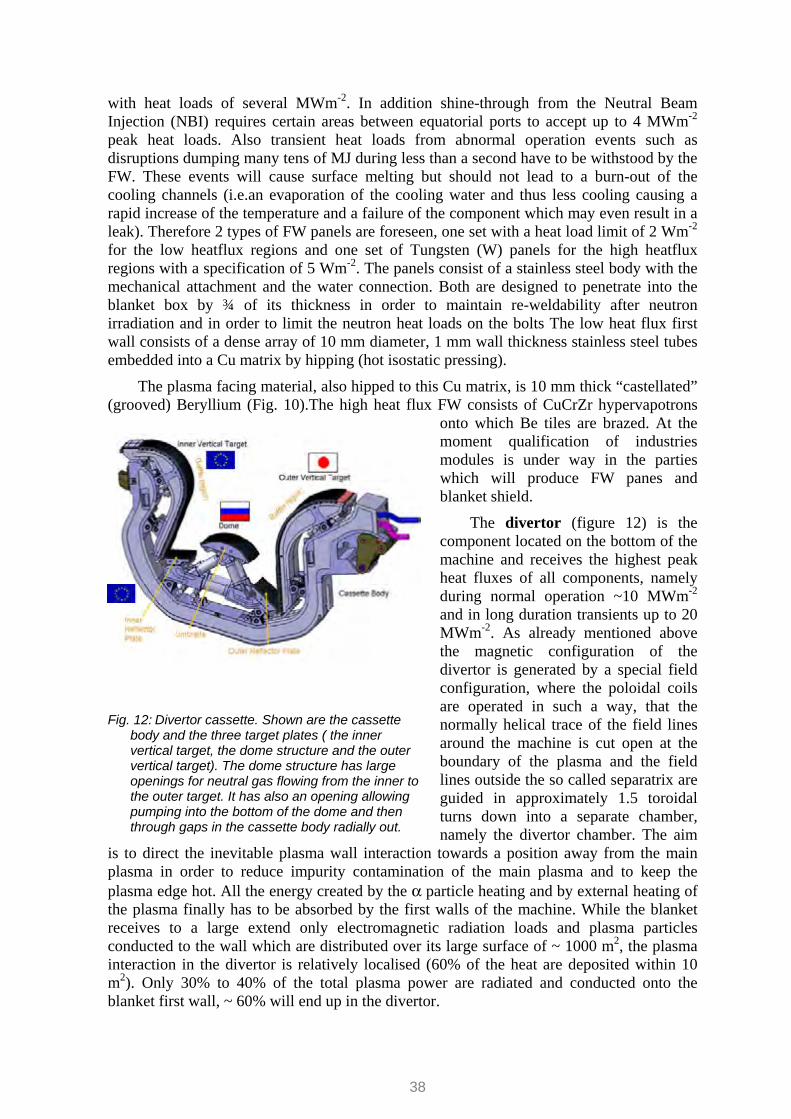
The divertor (figure 12) is the component located on the bottom of the machine and receives the highest peak heat fluxes of all components, namely during normal operation ~10 MWm-2 and in long duration transients up to 20 MWm-2. As already mentioned above the magnetic configuration of the divertor is generated by a special field configuration, where the poloidal coils are operated in such a way, that the normally helical trace of the field lines around the machine is cut open at the boundary of the plasma and the field lines outside the so called separatrix are guided in approximately 1.5 toroidal turns down into a separate chamber, namely the divertor chamber. The aim
is to direct the inevitable plasma wall interaction towards a position away from the main plasma in order to reduce impurity contamination of the main plasma and to keep the plasma edge hot. All the energy created by the α particle heating and by external heating of the plasma finally has to be absorbed by the first walls of the machine. While the blanket receives to a large extend only electromagnetic radiation loads and plasma particles conducted to the wall which are distributed over its large surface of ~ 1000 m2, the plasma interaction in the divertor is relatively localised (60% of the heat are deposited within 10 m2). Only 30% to 40% of the total plasma power are radiated and conducted onto the blanket first wall, ~ 60% will end up in the divertor.
Fig. 12: Divertor cassette. Shown are the cassette body and the three target plates ( the inner vertical target, the dome structure and the outer vertical target). The dome structure has large openings for neutral gas flowing from the inner to the outer target. It has also an opening allowing pumping into the bottom of the dome and then through gaps in the cassette body radially out.

39
The divertor consists of 54 cassette bodies made from stainless steel which form its structural backbone and distribute the coolant to the three different target modules in each cassette (Fig. 11). The cassette solution was mandatory for maintenance because in contrast to the blanket no access holes can be permitted on the divertor FW components due to the large heat loads present in the divertor. Therefore remote maintenance of these high heat flux (HHF) components is performed by removing and installing these 54 cassettes and by exchanging the divertor targets (HHF components) inside the Hot Cell where one can access the water coolant connections and the mechanical fixations of the targets from the side of the cassette.
The targets themselves also have a steel backbone onto which the high heat flux capable heat sinks are mounted [12]. The strong steel structures are required to withstand the electromagnetic loads already mentioned above. In the lower part of the vertical targets, a peak heat load of up to 20 MWm-2 can occur while the peak heat flux in all other areas of the divertor is normally in the order of 5 to10 MWm-2. For the first divertor to be installed in ITER in the highest loaded area CFC monoblocks are mounted on a coaxial tube with helical turbulence promoters (swirl tubes) as shown in figure 13, in all other areas W monoblocks or tiles are brazed to the CuCr Zr heat sink tubes or rectangular heat sinks. Monoblocks are CFC cubes (20 x 30 x 10 mm) or W sheets (20 x 30 x 5 mm) through which holes are drilled (figure 14). The CuCrZr tube is then fitted into these holes and either brazed to the CFC (or W) or hipped to a Cu interlayer casted onto the monoblocks
beforehand. This construction allows absorbing peak heat loads of 20 MW for extended durations (many seconds and many pulses (> 1000)). In less loaded areas of the divertor W tiles are brazed onto rectangular CuCrZr heat sinks.
The CFC targets at the bottom of the divertor are only a temporal solution for the non- active operation phase of ITER (i.e. the first ~4 to 5 years) before DT will be used in ITER and the machine will get radioactive. For the later phases the divertor will be changed to an all-W divertor, i.e. the CFC areas will be replaced by W monoblocks applying the same technology as described above. The rationale for the CFC targets in the early phase of operation (and thus during the learning phase of ITER operation) is that CFC does not melt during abnormal events like disruptions where several tens of MJ will be deposited onto the
Fig. 13: Design of the vertical targets. The lower part is made of CFC, the upper part of W. One can also see the helical turbulence promoters in the enlarged detail.
Fig. 14: A medium scale mock up produced for qualification by the EU-Domestic Agency. Again CFC and W are used. This mock up withstood successfully 2000 pulses at 20 MWm-2 on the CFC part and 18 MWm-2 on the W cladded part.

40
divertor. Until ELM stabilization etc. will be proven it is the more adequate material. However, CFC cannot be used during the nuclear operation phases of ITER because due to the very intensive C – H chemistry large quantities of T would be stored inside the ITER vessel causing eventually a safety concern. Therefore the divertor targets will be changed to al-W targets before nuclear operation starts, i.e. operation with DT.
The development of high heat flux components was supported by an extensive R&D. An example of a successfully tested medium-scale mock up is shown in figure 13. In the meanwhile also larger mock ups were tested and the development of a full W target was advanced in the area of high heat fluxes too. At the moment R&D has progressed to a large extent towards qualification of industrial processes to be able to start a “mass production” of the divertor targets in the next few years. This qualification is required, in particular for improving reliability and reproducibility in a series type manufacturing process during ITER construction in order to ensure the quality standards of these highly stressed components. Since ITER components are constructed by several members of the ITER agreement the involved industries in all these countries have to be qualified.
Remote maintenance is essential for reactor relevant fusion machines like ITER [13]. Already after a few DD discharges and in particular after only one single DT discharge of a few hundred seconds duration, the machine will be sufficiently activated that human access to the in vessel area is possible. Therefore remote maintenance is required for all in vessel
components including the port plugs. Due to the activation of these components they have to be also remotely repaired in a hot cell.
The divertor system is based on cassettes which are mounted on two strong rails (Figures 15, 16). The rails are also used for the remote maintenance machines. The divertor maintenance is performed by opening three ports and inserting a tool (radial mover) which removes two cassettes, namely the one in front of the port and the neighbouring one on the left side. Then a second machine is introduced (the toroidal mover) which has the shape of a cassette body and can move the cassettes along the rail to the open remote handling port where the radial mover then removes them from the vessel [14]. In this way the full replacement of a divertor takes less than 6 month, a time not too far from what will be needed for a fusion reactor where availability has to be maximised. The most time consuming operation, however, is not the moving and locking/unlocking of the cassettes but the cutting and welding of the water pipes providing the coolant to the cassettes. In particular weld preparation, positioning of the two ends accurately together and, after welding, tthe inspection of the weld and leak checking are time consuming tasks. All these
Fig. 15: shows the cassette radial mover bringing a new cassette
Fig. 16: shows the cassette toroidal mover after moving the cassette to its final position and fixing it there.

41
tasks have to be also performed by the two movers described above. To this end they have a manipulator with can be equipped with several different end actuators.
A first remote handling platform was built in Brasimone, Italy, during the nineties for the original large ITER machine design where the concept was tested successfully. A new platform has in the meanwhile been built in Finland which mimics the present design of ITER and thus the new geometry (Figure 17).
The remote maintenance of the blanket is more difficult than the one for the divertor because it has to be performed in 3-D [15]. The solution found was to install a rail in the centre of the plasma chamber (Fig. 18) supporting up to 4 vehicles which are able to grip blanket FW or shield modules, to dismantle their mechanical, electrical and water connections and to transport them to two ports, where a transport platform takes the modules out into a remote handling cask. A difficult task is the installation of the rail, which has to be delivered to the different ports in
pieces and then has to be assembled automatically. A large test facility was constructed and operated in Japan in order to proof the feasibility of this concept (Fig. 19).
Fig. 18: Blanket remote maintenance system. It is
based on a rail which is installed by the machines which are later running on it. Up to 4 machines can work simultaneously. The locking supports (yellow) and the transporter which brings blanket modules from the cask into the machine (green) can be also seen.
Fig. 19: R&D project for the blanket handling
system built in Japan. It has been demonstrated that such a system is feasible for the original larger ITER. For the current ITER design some improvements aimed at simplifications are needed.
Other ITER high tech components such as the heating systems, the fuel cycle and plasma diagnostics etc. are not described within the scope of this paper. For these systems an extensive design and R&D process also took place during the ITER EDA phase and beyond until today. In contrast to R&D for the main components this R&D was performed
Fig. 17: Remote handling platform for the ITER divertor constructed in Finland.

42
to a large extent not by industries but by the fusion laboratories which will have to play a significant role during the ITER construction period. In Europe several laboratories have formed consortia aimed at developing and constructing these peripheral components for ITER. Significant further R&D is necessary for the heating systems and the fuel cycle before these components can be procured and installed in ITER. Due to the fact that they will be needed relatively late in the machine assembly phases 2 and 3 (see below) there is adequate time left provided the present intensive and successful work in these areas continues.
4. The ITER construction schedule and initial operation
Fig. 20: ITER construction schedule, one can see the 2019 first plasma date and the following 2
assembly phases leading to a later DT operation which is not shown on this graph. The
critical path for the construction is shown in red, operation phases in light blue.
The ITER construction schedule was originally foreseen to last 10 years. However, it
became clear very soon that the ITER Organisation (IO) and the Domestic Agencies (DAs) of the different ITER partners who have to perform the procurement could not be built up sufficiently rapidly. Therefore this schedule could not be maintained. In addition the design of many ITER components required more time, also due to changes resulting from the design review which had to be implemented to ensure a fully consistent ITER design once the construction was agreed. A bit more than 2 years into the construction project it was then possible to establish a new realistic and lower risk construction schedule based also on the input from concrete procurement preparations in the DAs and their industry and on newly established costs. This updated schedule foresees a phased commissioning of the machine with a limited first plasma operation in 2019 and thereafter a succession of

43
assembly and operation phases. This updated schedule yields a completely assembled machine (including all heating and diagnostic systems as well as fuel cycle systems) by the end of 2023 and in early 2027 the start of full DT operation with the first experiments towards the objectives of Q=10 and 500 MW fusion power. Further optimization of this schedule may lead to some slight acceleration which would allow DT operation starting in 2026. The construction schedule is summarized in figure 20 (construction up to first plasma).
The above construction schedule and the revised overall project costs as well as the technical baseline of ITER will be presented to the ITER Council at its meeting in July 2010. It is expected that the Council will approve the baseline and that this schedule and cost can be realistically achieved by the combined organisations of IO and DAs.
Literature
[1] G. McCracken, P. Stott, “Fusion : The Energy of the Universe”, ELSEVIER Academic Press
[2] ITER Physics Basis: ITER Physics Basis Editors et al 1999 Nucl. Fusion 39 2137
[3] Progress in the ITER Physics Basis: Editors of 'Progress in the ITER Physics Basis' et al 2007 Nucl. Fusion 47 S1
[4] ITER Final Design Report, IAEA Vienna 2001
[5] G. Janeschitz, et.al., “A !- D predictive model for energy and particle transport in H-mode”, Plasma Phys. Contr. Fus 44 (2002) A459 – A471
[6] G.W. Pacher, H.D. Pacher, G. Janeschitz, , A.S. Kukushkin, Nucl. Fusion 48 (2008) 105003 (26pp)
[7] R. J. Hawryluk, et al, Nucl. Fusion 49 (2009) 065012
[8] ITER Plant Description Document (2009) available in the ITER Document Management System (IDM) PD - Plant Description (2X6K67) (https://user.iter.org/?uid=2X6K67 )
[9] F. Savary, A. Bonito-Oliva, R. Gallix, Status Report on the Toroidal Field Coils for the ITER Project, to be published in the proceedings of MT-21, (2009)
[10] K. Ioki et al. Fusion Engineering and Design 84 (2009) 229–235
[11] M. Merola, et.al., ITER In Vessel Components, to be published in the proceedings of ISFNT-9, (2009)
[12] C. Lowry, et.al., ITER-PFCs, IAEA Fusion Energy Conference, (2008), IT-1-4
[13] A. Tesini and J. Palmer, “The ITER remote maintenance system,” Fusion Engineering and Design Volume 83, no. 7-9 (December 2008): 810-8
[14] J. Palmer et al., “The design and development of divertor remote handling equipment for ITER,” Fusion Engineering and Design 82, no. 15-24 (October 2007): 1977-1982
[15] Masataka Nakahira et al., “Design progress of the ITER blanket remote handling equipment,” Fusion Engineering and Design 84, no. 7-11 (June 2009): 1394-1398
Dr. Günter Janeschitz ITER Organisation CS 90046 F-13067 St. Paul Lez Durance CEDEX France
Energie Technologien für die Zukunft
Vorträge auf der DPG-Frühjahrstagung in Bonn 2010
Arbeitskreis Energie in der Deutschen Physikalischen Gesellschaft Herausgegeben von Hardo Bruhns
Bad Honnef, April 2011

3
Frühjahrstagung des Arbeitskreises Energie
in der Deutschen Physikalischen Gesellschaft
Bonn, 15. und 16. März 2010
Hauptvorträge
Inhaltsverzeichnis
Einleitung ...................................................................................................................................... 5
Übersicht über die Fachsitzungen ................................................................................................. 7
Abstracts ....................................................................................................................................... 8
Energieeffizienz in der Informationstechnologie (vorgetragen von W. Gnettner) ..................... 18
ITER, the Decisive Step towards Fusion Energy (vorgetragen von G. Janeschitz) ................... 29
The Physics Base for ITER and DEMO (vorgetragen von H. Zohm) ........................................ 44
Neue Reaktorenkonzepte für die Kernspaltung, Entwicklungen von AREVA (vorgetragen von W. Dams) .................................................................................................................... 55
Brennstoffzellen für mobile Anwendungen – Wo stehen wir auf diesem Weg? (vorgetragen von D. Stolten) .................................................................................................................. 67
Elektrische Energiespeicher (vorgetragen von M. Rzepka) ....................................................... 77
Strom aus solarthermischen Kraftwerken im Sonnengürtel (vorgetragen von R. Pitz-Paal) ..... 90
Stromtransport: Erfordernisse und Lösungen für ein europäisches Verbundnetz unter Nutzung solaren Stroms aus Nordafrika (vorgetragen von T. Benz) ................................ 97
Intelligente Stromnetze - Perspektiven und Potenziale (vorgetragen von F. Schulte) ............. 108
Geothermische Stromerzeugung - Vom Reservoir bis zur Turbine (vorgetragen von E. Huenges) .......................................................................................................................... 114
Energie aus Biomasse – Perspektiven für Europa (vorgetragen von D. Thrän) ....................... 126
Thermodynamisch optimiertes Heizen und Kraft-Wärme-Kopplung (vorgetragen von G. Luther) ............................................................................................................................. 137

4
Der vorliegende Band fasst schriftliche Ausarbeitungen der Hauptvorträge der AKE Tagung des Jahres 2010 in Bonn zusammen. Leider ist es nicht gelungen, von allen Vortragenden Manuskripte zu erhalten. Die Präsentationsfolien aller Hauptvorträge können auf der Webseite des Arbeitskreises über:
http://www.dpg-physik.de/dpg/organisation/fachlich/ake.html
(von dort zu dem Archiv des AKE weiterklicken) eingesehen werden. Allen, die zu diesem Sammelband beigetragen haben, sei an dieser Stelle sehr herzlich gedankt.
Düsseldorf, im Dezember 2010 Hardo Bruhns