issue 2 2019 the arup journal...6 2/2019 | the arup journal 7 architect and contractors, worked...
TRANSCRIPT

The Arup Journal
The Arup Journal Vol.54 No.2 (2/2019) Editor: Macdara Ferris Designer: Wardour Email: [email protected]
1. Coal Drops Yard, London, UK: Daniel Imade/Arup; 2. Scott Hall, Carnegie Mellon University, Pittsburgh, USA: Bitterman Photography; 3. China Zun, Beijing, China: Wentao; 4. UK Autodrive, Milton Keynes and Coventry, UK: Fabio De Paola/PA Wire; 5. Cultana PHES, Spencer Gulf, Australia: Arup; 6. V&A Dundee, Dundee, Scotland, UK: Ross Fraser McLean.Front cover image: Coal Drops Yard, London, UK: Luke Hayes
Published by Arup 13 Fitzroy Street London W1T 4BQ, UK. Tel: +44 (0)20 7636 1531 All articles ©Arup 2019
www.arup.com
1
4
5 6
2
Printed by Geoff Neal Group Produced on FSC paper and printed with vegetable- based inks.
Issue 2 2019
3
Issue 2 2019The A
rup Journal

32/2019 | The Arup Journal2
Contents
China Zun, Beijing, China: Wentao
4 Coal Drops Yard, London, UK Regenerating a historical railway site in central London
Simon Bateman, Stuart Chambers, Ed Clark, Richard Hill, Peter Lenk, Sarah Tattersall, John Walton
30 UK Autodrive, Milton Keynes and Coventry, UK A pioneering project demonstrating connected and autonomous vehicle technology
Tim Armitage, Danielle McGrellis, Ralph Wilson
36 Cultana Pumped Hydroelectric Energy Storage, Spencer Gulf, Australia Creating a secure, sustainable energy future for South Australia
Rhys Anderson, Matt Lloyd-Smith
40 V&A Dundee, Dundee, Scotland Engineering a complex building for Scotland’s first dedicated design museum
Wayne Butler, Dan Clipsom, Graeme Moncur, Martin Surridge
14 Scott Hall, Carnegie Mellon University, Pittsburgh, USA Creating a high-tech, collaborative facility on challenging terrain
Jeffrey Huang, Matt Larson, Carl Mister, Raymond Quinn, Joe Solway
20 China Zun, Beijing, China An iconic landmark that leads the way in fire safety and seismic design
Yu Cheng, Peng Liu, Kelvin Wong

4 52/2019 | The Arup Journal
COAL DROPS YARD | LONDON, UK
A Victorian heritage site adapted for 21st-century LondonThe regeneration of Coal Drops Yard has breathed new life into a historical railway area, transforming it and ensuring it has a long future
Authors Simon Bateman, Stuart Chambers, Ed Clark, Richard Hill, Peter Lenk, Sarah Tattersall and John Walton
1: The ‘kissing point’, where the two buildings almost meet, is the centrepiece of the development
2: Coal Drops Yard has a rich history, which Arup and Heatherwick Studio sought to preserve while also modernising the complex
1. 2.
Coal Drops Yard is the centrepiece of the regeneration of King’s Cross, a part of central London that has undergone rapid change in recent decades. The railway section of King’s Cross encompassed many feats of Victorian engineering, but during the 20th century the area had become rundown. This new development has created a vibrant city quarter with boutiques, restaurants, bars, cafés and public space. Located in the heart of the capital, it makes use of two 19th-century railway buildings that over the past 150 years have been used for everything from coal distribution to warehouses and nightclubs.
Arup worked with designers Heatherwick Studio to sensitively restore the existing fabric of the structures, while adding a series of imaginative contemporary design features. The most striking element of the scheme is a breathtaking sculptural pitched roof that unites the two buildings while creating a lively public plaza beneath and a dramatic glazed retail unit for an anchor tenant. The two main components of the roof curve upwards to come together at a ‘kissing point’. Seen from above, this is the only point at which the two buildings meet. Below, a new walkway on top of the historical viaducts snakes around the development and is linked via three new bridges, allowing visitors to navigate the area while enjoying views of the roof’s dramatic glazed form. The blue-grey slate on the roof was sourced from the same quarry as the tiling on the original buildings, a nod to the development’s heritage despite its thoroughly contemporary aesthetic.
Aside from realising a structurally and architecturally ambitious design, the major challenge was to find ways of integrating the new elements of the design into the original fabric in a way that was sensitive to the features of historical importance, but also meant the buildings would meet modern needs.
Arup brought together a team that had broad design vision, as well as deep technical expertise in heritage, digital construction, materials, geotechnics, structural
engineering and façades. Together, they rejuvenated this formerly derelict part of London, which is now buzzing with energy, activity and visual inspiration.
Regenerating King’s CrossThe aim of Coal Drops Yard was to create a destination towards the north of the King’s Cross area that would draw visitors from the transportation hubs to its south and across the canal that cuts through the area. One of the main tasks involved restoring and connecting two brick buildings from the 1850s, which

6 72/2019 | The Arup Journal
architect and contractors, worked together in a digital environment, and advanced digital tools were used to plan the process. Initially, a point cloud survey and a laser scan with an accuracy of ±5mm were used to model the existing buildings. This data was then used to develop an integrated model that overlaid all the new elements onto the structure, including building services, envelope, finishes and architecture. Heatherwick Studio and Arup also used a combination of digital modelling and 3D printing to review a number of iterations of the roof shape when undertaking this element of the building design.
Historical restorationOriginally, the two Coal Drops buildings, 150m and 120m in length, had railway tracks
structures on the site includes engineering the Grade II-listed Gasholder No. 8, the Midland Goods Shed and the Stanley Buildings. The Coal Drops Yard project, which Arup began working on in 2012, was a particularly complex, unusual and architecturally ambitious element of the area’s redevelopment, as it involved dealing with sensitive heritage structures, as well as creating the complex roof. Arup worked closely with Heatherwick Studio from the start of the project to devise engineering solutions that made the most of the area’s Victorian character, while also creating a new contemporary identity for the development.
Advanced digital processesCoordinating the design and construction process of this vast project was a complex undertaking. State-of-the-art surveying techniques were used, as were building information modelling (BIM) processes and workflows to help overcome the many complex design challenges. The different engineering disciplines, as well as the
extended into the upper levels. Wagons would be drawn through them manually using ropes and horses (steam locomotives would have presented the risk of fire). Voids between the tracks allowed coal to be poured into hoppers at mezzanine level. In turn, these hoppers released coal into bags on horse-drawn carts that could be driven into each of the bays on the ground floor. The coal was then distributed across London.
Arup conducted a forensic assessment of the existing buildings to understand their structural arrangement and condition, discovering decayed timber, cracked masonry and corroded ironwork, as well as extensive structural deterioration. The team assessed the load-carrying capacity of the buildings,
features – including cobbled streets, viaducts and ironwork – remained.
For 35 years, Arup has been instrumental in the transformation of the King’s Cross area. This includes the landmark redevelopment of the two train stations, Grade I-listed St Pancras International and Grade I-listed King’s Cross. Following the completion of St Pancras and the arrival of Eurostar services, Arup has worked closely with the developer, Argent, on redeveloping other buildings across the 67-acre former industrial wasteland. Arup’s work on historical
3: The development is part of the larger King’s Cross area regeneration, which has included turning the old gasholders into prime living spaces
4: The site has been used for many purposes over the years, but several of the original features remain, including the Victorian brickwork and ornate ironwork
5: State-of-the-art digital tools were used to plan the project, including an integrated model of the two buildings and the complex roof structure
then Arup’s conservation-accredited engineers designed the floor strengthening and the timber and iron roof truss repairs. Cracked and decayed brickwork was repaired, and the façade was stitched back together using 1.5m-long anchors discreetly embedded within the masonry walls.
Redeveloping the eastern Coal Drops building, which was constructed in 1851, was a particular challenge for the engineering team, due to its substantial deterioration caused by fire and water damage. The Grade II-listed building had a brittle cast-iron and masonry structure. The mezzanine floor consisted of timber joists spanning cast-iron beams and brick walls, with the beams in turn supported on either circular cast-iron columns or on the brick spine wall at the centre of the building. As part of the historical casting process, cylindrical timber poles were used to form hollows inside the cast-iron columns. However, the use of these timbers, which float slightly during the casting process, often resulted in columns that were thicker on one side than the other. Small air bubbles were entrained in the molten metal during the casting, resulting in additional weak spots in the structure.
Arup carried out detailed analysis to assess the strength of each of these handmade columns. In some cases, columns were relocated within the building, depending on their capacity to carry weight and the varying loads across the structure. This strategy meant that the original fabric of the buildings could be preserved, while making sure that the columns could support the new loads that were to be imposed upon them
COAL DROPS YARD | LONDON, UK
had originally been used to store coal that arrived in London from the north of England by train. As coal usage declined, these buildings were abandoned, and over the years they have been used for a variety of activities, serving as offices, workshops and nightclubs, before being partially abandoned. In the 1980s, a fire devastated the eastern Coal Drop – the roof and much of the floor structure were lost and decades of exposure to the weather led to substantial further deterioration. Despite this decay and the informal and varied use of the buildings over many years, much of the area’s historical
3.
4. 5.
6. 7.
8.
6: The buildings originally consisted of three floors; Arup rationalised this design in places
7: The historical handmade columns had to be tested to ensure they had sufficient strength for the building’s new use
8: Arup’s design involved dismantling and then repositioning the original timber floors in a number of locations

8 92/2019 | The Arup Journal
(modern retail units are heavier than the coal trucks that the building previously had to support). The new loads also put pressure on the walls between the bays, which had been constructed with shallow masonry foundations. To ensure the walls could support the additional weight, excavations of up to 3m were carried out to allow new concrete foundations to be constructed.
Rationalising and reinforcing the floorsIn both the eastern and western Coal Drops buildings, Arup’s design saw the dismantling and repositioning of the timber floors in order to meet accessibility criteria and to align with the new external bridges. There were three levels in the original buildings: the top, into which trains were driven; the middle level, in which coal was processed; and the yard level below, where carts were brought in. The three floors, which had fairly low ceilings, were not appropriate for the retail usage planned for the site, so the design team rationalised the scheme to create two floors across most of the structure. The plan was that the yard level floor would stay as it was and the upper two floors would be unified into a single level that would allow step-free access to the external walkways. Where possible, the existing timber floors were repaired and moved, with the joists and floorboards taken out and reinstalled at the new level. Where the original materials were no longer viable, new steel floors were installed.
still required, but the need for this was much reduced by Arup’s strategy.
To retain a sense of the original architecture, two of the retail units – the northern and southern anchor units – were kept at three storeys. In the southern anchor unit, the original timber floors were retained, but in the northern unit the floors had to be rebuilt using steel decking topped by a concrete infill. While this is standard for commercial buildings, the context here made it unusual. In the rest of the building, the roof had been removed so the steelwork could be inserted through the top of the building; but here, holes had to be created in the walls to carefully thread the steel frame through the building without removing large chunks of the brickwork.
Arup’s careful work on retaining and restoring as much of the original buildings as possible was an exercise in sustainability. It also means that historical structures that were previously inaccessible to the public are now open for the first time. Historic England has commended the “very significant heritage benefits arising from the repair and reuse of the buildings”.
Roof and floating floorMoving away from the cellular nature of the two former warehouse buildings, one larger retail unit was created for a major anchor tenant. The new floating floor between the buildings was designed for that unit and to make a strong visual statement. One of the earlier designs had proposed merging the two buildings with a unified roof. However, the local authority and Historic England required that the two existing buildings remain distinct entities, so the architectural design evolved to create a solution where the two roofs would just about touch.
The floors are supported on the existing walls wherever possible. However, in some areas, when the structural loads were assessed, the weight of the new retail units was shown to exceed the historical loading. The new roof also adds substantial extra weight. Supporting all these elements on the original structure risked resulting in excessive movement that would damage the existing walls and foundations. To support the additional weight, Arup included new
COAL DROPS YARD | LONDON, UK
10.
9.
9: The existing structure was retained or reused wherever possible, with new steelwork inserted as required
10: Extensive roof refurbishment was required on both the western (shown in picture) and eastern Coal Drops buildings
11: The anchor units at the northern and southern ends of the development were kept at three storeys
11.
independent steel columns. These sit against the brick walls that divide up the interior, separating the individual retail units. To support the new columns, reinforced concrete pile foundations were inserted to 25m below ground. Relying on the existing foundations would have required heavy underpinning of all the walls to give them sufficient strength, and would also have meant that local reinforcing of the walls would have to be undertaken.
Depending on the load requirements, one or two piles per column – a mix of 300mm, 450mm and 600mm in diameter – were used. These were placed approximately 800mm from the wall, depending on the space available. Building these foundations presented its own challenge, as they had to be constructed inside the existing building. Operating the piling rigs within the narrow, low bays was a painstaking task, as was the need to make sure the piles could be built as close to the walls as possible. If smaller piles were used, more would be needed, so this would be costlier; however, the larger the piles, the bigger the rig needed to install them. A compromise was reached: in the western Coal Drop, where there was more room, 450mm diameter piles were mostly used. In the eastern Coal Drop, which had stricter space constraints, 300mm piles were installed, so a smaller rig could be used. New foundations could not be built in all places due to the walls’ state of deterioration, so some underpinning was

10 112/2019 | The Arup Journal
two buildings. Inclined rafters connect at the apex of the roof and are tied across at their base to form the A-frame, reducing the pressure on the twisted arches that form the edge of the peeled sections of roof. At the apex, a V-shaped component – referred to as the kissing point – was inserted to allow the structure to remain within the sculptural roof profile and to transfer forces across this critical junction. The overall result is a closed structural system with no horizontal thrusts exerted onto the supporting structure.
The floor of the new anchor store is suspended from the new roof, spanning the perimeter of the existing buildings and hangers that connect to the bottom chord of the peel trusses. This configuration set up a delicate structural balance in the behaviour of the peel trusses. Due to their curved and inclined geometry, these have a tendency to twist under vertical load. However, as the floor hangers connect to the bottom chord of these trusses, and are eccentric to the centre of gravity of the truss, they exert a counter-twist that helps to minimise the overall rotation and the degree of restraint that has to be provided by the rafters.
Once the structural concept for the roof and floor had been fixed, Arup embarked on refining the structural arrangement further. The team manually optimised the structural topology based on experience and intuition. The aim was to minimise the steelwork tonnage while also simplifying steelwork connections and piece count. Subsequently, an automated process for the more detailed optimisation of the section sizes took place, with the overall result of these refinements being a reduction in tonnage of 30% compared with the original plan.
SteelworkThe majority of roof steelwork was broken into large fabricated sections that were transported to site, assembled and then lifted into position on temporary trestles. Jacking points were incorporated at each temporary support location. Prefabricating elements meant minimum assembly was required on site and that temporary works and the need to work at a height were also reduced. In putting the elements together, steel contractor Severfield UK adopted the innovative strategy
COAL DROPS YARD | LONDON, UK
12: Section showing the tied A-frame roof structure and hung floor
13: A V-shaped component was inserted into the roof structure to transfer the loads at the apex of the roof
14: Maquette of the roof design concept
15: 3D model of the primary roof structure
16: Most of the roof steelwork was prefabricated off site and then lifted into place
17: The two roofs lean together over the 33m wide central courtyard
16.
13.
17.
400SHSvertical
610CHS Middle Chord
2No 1000 Deep x 600 WideGiraffe Girders
2No 1300 Deep x 1500 WideFabricated steel boxes boltedtogether
Internal Stiffenersat regular intervals
40mm Web
Sectional area of Ribbon Chordspasses through fabricated boxas a stiffened plate
80mm Plate
80mm Top Flange
80mm Bottom Flange
Internal Stiffenersat regular intervals
2No 1000 Deep x 600 WideGiraffe Girders
2No Internal stiffeners perfabricated box to transfer axialforce from Giraffe Girders into
Webs of Fabricated Box
610CHS Bottom Chord
Bottom Flange of Fabricated box formed from a continuous bent flat plate
900mm MIN
A0
Do not scale
A B C D E F G H I J K L M N
1
O P Q R S T U
2
3
4
5
6
7
8
9
10
11
12
13
14
15
Rev Date By Chkd Appd
Client Project Title
© Arup
V W
Scale at A0
Suitability
Name
Arup Job No
Role
Rev
Drawing Title
Rev Date By Chkd Appd
08/0
3/20
1618
:56:
34
1 : 20
Coal Drops YardKing's Cross Central GeneralPartner Ltd
13 Fitzroy StreetLondon W1T 4BQTel +44(0)20 7636 1531 Fax +44(0)20 7580 3924www.arup.com
219870 05
Construction Issue
Roof Structure DetailsSheet 2
Structural
KXC-M0-001-ARP219870-S-(20)502001
Notes1. Refer to General Notes drawing KXC-M0-001-ARP219870-S-(10)701 for general notes and guidance.
2. Refer to drawing KXC-M0-001-ARP219870-S-(10)702 to-S-(10)705 for member schedules.
3. The existing structure shown on these drawings is based on the Architect’s BIM model and was derived byPlowman Craven Associates from their point cloud survey. The contractor is to verify the existing structure, itscondition and details on site for all locations and check that the design is achievable following full opening up andinvestigation.
4. Existing masonry shown is indicative only and is based on the architect's existing structure model anddemolition drawings. Extent of existing masonry to be confirmed on site by Contractor. For extent of proposeddemolition refer to the latest architectural drawings.
1 : 203
02 19/10/15 RAB ET EC
Stage 4
03 10/11/15 RAB MW EC
Stage 4
04 18/11/15 RAB MW EC
Stage 4 Update
05 08/03/16 RAB MW EC
For Construction
14.
12.
15.
The proposal emerged through a collaborative process of digital and physical modelling. To start, Heatherwick Studio and Arup conducted a series of workshops, with the aim of assessing various configurations. Multiple rapidly printed 3D prototypes were made over several days to assess different designs, from both an architectural and structural perspective, and to evaluate how different roof shapes affected the public space underneath, redesigning as required. The use of 3D printing and digital modelling allowed the team to cycle through multiple iterations in rapid succession, far more than on a traditional project. This process married the idea of traditional model-making with technology, a method of working that is becoming increasingly common but was fairly unusual at the time.
The visually stunning final design created serious engineering challenges. The two roofs extend out over the 33m-wide central courtyard while supporting the floating floor below, with the primary structure configured to follow the roof geometry and to cause
minimal visual interference. Initial design discussions proposed propping the floor off the adjoining viaducts, which would have been easier to build, as it would disconnect the floor from the roof. However, such an arrangement would have destroyed the visual drama that the designers intended to create, as well as removing the illusion of lightness.
Arup set about devising a system of support that would be invisible and integrated. The first proposal was to consider the two sections of peeled roof as inclined trussed arches leaning on each other and tied along the inner façade of each building. The aim was to have no structure passing through the connection point. However, this arrangement led to a primary span of approximately 85m along the length of the site and, given that the distance between the far walls of the two buildings was only 60m, this seemed inefficient and wasteful.
The final solution includes a tied A-frame spanning the shortest point between the
of using air hoists within the rigging equipment to manipulate the complex curved roof steelwork in the air before it was rested in its correct orientation. Once the roof structure was erected on the supporting trestles and the bolting process was completed, the roof was de-propped, allowing the steelwork to take up load induced by its own weight. The temporary trestles were then removed.
The steelwork in the roof was designed and fabricated to a preset geometry, with the aim
Two internal stiffeners per fabricated box to transfer axial force from giraffe girders into webs of fabricated box
Internal stiffeners at regular intervals
80mm bottom flange
Two 1,300mm deep x 1,500mm wide fabricated steel boxes bolted together
Bottom flange of fabricated box formed from a continuous bent flat plate
Two 1,000mm deep x 600mm wide giraffe girders
400SHS vertical
80mm plate
610CHS middle chord
Sectional area of ribbon chords passes through fabricated box as a stiffened plate
Internal stiffeners at regular intervals
80mm top flange
40mm web610CHS bottom chord
Two 1,000mm deep x 600mm wide giraffe girders

12 132/2019 | The Arup Journal
minimising additional work where possible, and deciding where new structure was unavoidable, or where it would provide greater benefit and help realise the client’s vision. The project won the Bazalgette Award for Sustainability at the Institution of Civil Engineers’ 2019 London Awards.
A new lease of lifeThe dramatic roof was the defining feature of the project and, as such, all engineering efforts were geared around creating the iconic kissing point. Working closely with Heatherwick Studio and all the contractors and specialists involved in the project, Arup navigated the risks and complexities of the scheme, ultimately delivering a visionary and superbly engineered project that does justice to the area’s heritage and sets it up for the future.
of compensating for the predicted deformations that would occur when it was hanging. The plan was to ensure that both the roof and suspended floor would settle to a flat, level position at the point of completion. This required points of the roof steelwork to be fabricated up to 90mm away from their final positions.
Predicting and controlling the movement of the roof structure during construction was a particular engineering challenge, as it relied on the accuracy of the team’s analysis and the quality of the fabrication process. Working with Severfield UK and principal contractor BAM, Arup monitored and surveyed the tolerances and movement of the structure at critical stages throughout the fabrication and installation process (while building the structure, hanging the floating floor below and gradually removing the temporary supports it was built on). Throughout this process, Arup mapped exactly where the structure was, compared with where it was predicted to be in the digital model, and adjusted accordingly. The final position of the floor slab was level to within the standard tolerances.
Glazing the anchor unitUsing the full capabilities of structural glass, Arup’s façade engineers were able to deliver the fully glazed façade that encloses the
support and weather and air tightness. Vertical glass connections transfer axial and shear forces between the units.
Tests were carried out to eliminate the potential risk of water ingress and to predict façade behaviour and identify possible failure modes. This was necessary because silicone-bonded structural glass walls are susceptible to the movement of the primary structure, which, in this case, is complex and hard to predict. Each glass panel is supported on a central rocker that transfers deflection of the primary structure into vertical movements in between glass panels. Horizontal drifts, as well as vertical deflections occurring after the glass walls are connected with structural silicone, will stress those joints. A full-scale performance mock-up experiment was conducted to confirm the results of advanced analysis of the structure.
SustainabilityArup took an integrated approach to sustainability, with three central elements to its plan. First, the ambition was to retain and reuse as much of the original buildings as possible, including using the existing walls and floors to carry structural loads where viable, minimising the need for fresh construction work and new foundations.
Second, wherever new construction was needed, Arup aimed to minimise the
embodied carbon of the new structure and operational energy of the building. For example, the energy performance of the façade is better than that of a typical curtain wall system. This is because cold bridges (where glass meets aluminium) are not present. In addition, a carefully selected solar coating provides protection from overheating without the need for external shading devices, as well as providing high light transmission and colour stability.
Third, sustainability was thought of in a wider sense – in terms of creating a cultural destination that would promote economic growth, catalyse the area’s regeneration and create social benefits through greater provision of public space. Arup’s role was to navigate a path between these three factors,
COAL DROPS YARD | LONDON, UK
raised retail unit without the need for an additional supporting structure. Exploiting the facade’s serrated geometry, each piece of glass supports its neighbour. Structural silicone double-glazed units at vertical edges, which were applied in situ, provide additional
19.
20.
18: The raised retail unit has a fully glazed façade, the design of which means it does not need any additional supporting structure
19: The new Coal Drops Yard development has brought a new lease of life to this part of central London
20: As well as being visually striking, the glazed façade has a better energy performance than a typical curtain wall system, as there are no cold bridges
18.
AuthorsSimon Bateman was the Project Manager. He is a senior structural engineer in the London office. Stuart Chambers is a senior structural engineer in the London office.
Ed Clark was the Project Director. He is a Director in the London office.
Richard Hill is a conservation-accredited structural engineer. He is an Associate Director in the Advanced Digital Engineering team in the London office.
Peter Lenk led the façade element of the project. He is an Associate in the London office.
Sarah Tattersall is a conservation-accredited structural engineer. She is an Associate in the Advanced Digital Engineering team in the London office.
John Walton worked on the heritage elements of the project. He is a senior structural engineer in the Advanced Digital Engineering team in the London office.
Project creditsDeveloper ArgentArchitect Heatherwick Studio Principal contractor BAMSteel contractor Severfield UKHeritage, materials, geotechnical, structural and façade engineering Arup: Melody Ablola, Alejandra Albuerne, Carolina Bartram, Simon Bateman, Rick Benjamin, Emma Boucher, Jon Butler, Stuart Chambers, Jake Cherniayeff, Tom Clack, Ed Clark, Chris Clarke, Tara Clinton, Aifric Delahunty, Christian Dercks, Marc Easton, Laura Evelyn, Lee Franck, Jennie Gates, Elisa Hernandez Montero, Richard Hill, Yue-Qi Hou, Bogdan Huiu, Paul Jeffries, Andrew Lawrence, Peter Lenk, Hunter Lyden, Vladimir Marinov, Rich May, Tim Morgan, Akis Pasalidis, Jenny Pattison, Barrie Porter, Andrew Ramsay, Alex Reddihough, Morgan Rhodes, Darryl Tanner, Sarah Tattersall, Elena Todorova, Bernard Travers, Edward Tricklebank, Theo Tsongidis, Marianne Walsh, John Walton, Mick White.
Image credits1, 18: Hufton + Crow2, 5, 10, 12–17: Arup3, 6–9: Paul Carstairs/Arup4, 11: Daniel Imade/Arup19, 20: John Sturrock
14 152/2019 | The Arup Journal
SCOTT HALL, CARNEGIE MELLON UNIVERSITY | PITTSBURGH, USA
A low-energy, high-tech landmark laboratory
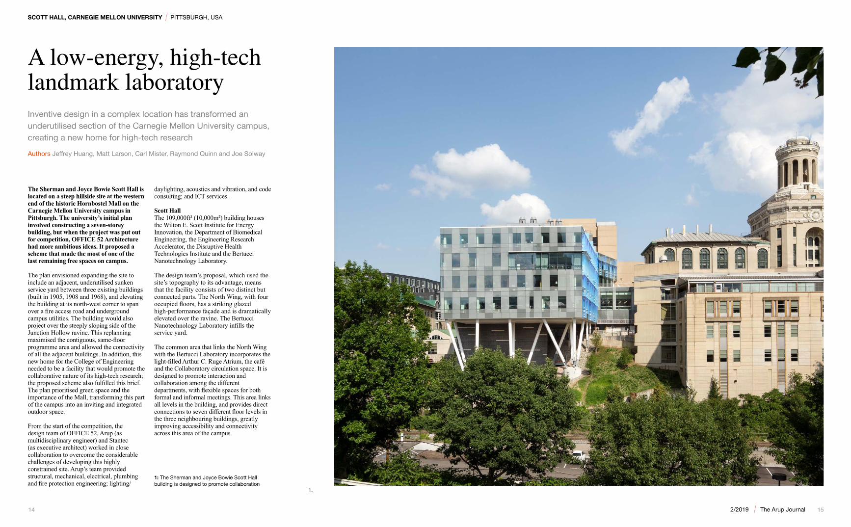
The Sherman and Joyce Bowie Scott Hall is located on a steep hillside site at the western end of the historic Hornbostel Mall on the Carnegie Mellon University campus in Pittsburgh. The university’s initial plan involved constructing a seven-storey building, but when the project was put out for competition, OFFICE 52 Architecture had more ambitious ideas. It proposed a scheme that made the most of one of the last remaining free spaces on campus.
The plan envisioned expanding the site to include an adjacent, underutilised sunken service yard between three existing buildings (built in 1905, 1908 and 1968), and elevating the building at its north-west corner to span over a fire access road and underground campus utilities. The building would also project over the steeply sloping side of the Junction Hollow ravine. This replanning maximised the contiguous, same-floor programme area and allowed the connectivity of all the adjacent buildings. In addition, this new home for the College of Engineering needed to be a facility that would promote the collaborative nature of its high-tech research; the proposed scheme also fulfilled this brief. The plan prioritised green space and the importance of the Mall, transforming this part of the campus into an inviting and integrated outdoor space.
From the start of the competition, the design team of OFFICE 52, Arup (as multidisciplinary engineer) and Stantec (as executive architect) worked in close collaboration to overcome the considerable challenges of developing this highly constrained site. Arup’s team provided structural, mechanical, electrical, plumbing and fire protection engineering; lighting/
daylighting, acoustics and vibration, and code consulting; and ICT services.
Scott HallThe 109,000ft² (10,000m²) building houses the Wilton E. Scott Institute for Energy Innovation, the Department of Biomedical Engineering, the Engineering Research Accelerator, the Disruptive Health Technologies Institute and the Bertucci Nanotechnology Laboratory.
The design team’s proposal, which used the site’s topography to its advantage, means that the facility consists of two distinct but connected parts. The North Wing, with four occupied floors, has a striking glazed high-performance façade and is dramatically elevated over the ravine. The Bertucci Nanotechnology Laboratory infills the service yard.
The common area that links the North Wing with the Bertucci Laboratory incorporates the light-filled Arthur C. Ruge Atrium, the café and the Collaboratory circulation space. It is designed to promote interaction and collaboration among the different departments, with flexible spaces for both formal and informal meetings. This area links all levels in the building, and provides direct connections to seven different floor levels in the three neighbouring buildings, greatly improving accessibility and connectivity across this area of the campus.
Inventive design in a complex location has transformed an underutilised section of the Carnegie Mellon University campus, creating a new home for high-tech research
Authors Jeffrey Huang, Matt Larson, Carl Mister, Raymond Quinn and Joe Solway
1.
1: The Sherman and Joyce Bowie Scott Hall building is designed to promote collaboration

16 172/2019 | The Arup Journal
furthest from the rail line and having the advantage of the laboratories being built on grade – rather than elevated floor slabs – significantly improved the vibration environment, thereby reducing construction complexity and costs. An 18in (457mm) deep ground-bearing slab achieves VC-E and VC-D based on recorded ambient site vibrations, and performs to VC-D for footfall-induced vibrations.
Laboratory systemsAccurate regulation of temperature and humidity is essential to the research carried out in the 11,000ft² (1,000m²) cleanrooms and the surrounding research spaces, and the class 10/100 cleanrooms require high air change rates. The process systems and the high-tech tools used in the laboratory mean there is a substantial cooling load and, owing to the 24/7 operation of the spaces, continuous cooling capability is needed. Although the cleanroom is only 13% of Scott Hall’s area, energy modelling showed it accounted for approximately 50% of the building’s overall energy use. It was essential
that the systems minimised energy usage as far as possible. Arup’s design incorporated cost-effective, low-energy measures, including energy recovery systems, cascaded water loops to increase the temperature difference between the supply and return water temperatures, limited humidification, variable laboratory air change rates and reductions in lighting power density. The greatest efficiencies were achieved by improving fan performance and, using occupancy sensors, allowing a setback condition when spaces are vacant.
Working closely with cleanroom designer Jacobs, Arup designed the essential building services for the facility. These included chilled water, power and controls, and the exhaust and make-up air controls. The design controls the regular extraction of hazardous gases from the space. The air management system provides temperature stability across the cleanroom of ± 0.5°F and humidity within ± 2% relative humidity, with the clean bays certified at rest as meeting the ISO 14644 Class 1 standard.
The energy performance for the cleanroom is 9,960 cu ft/min/kW.
Arup also worked with the university’s Environmental Health and Safety Department on the design for management of hazardous gases and fire alarm operations for the pyrophoric and toxic gases that are used in the cleanroom.
Isolation requirements for the mechanical and electrical equipment within the building were specified by Arup. In collaboration with the electro-acoustic consultant, the firm ensured no stray electromagnetic interferences were created by the electrical infrastructure.
Green roofThe Bertucci lab consists of a concrete frame with 24in (610mm) square columns on a
30ft x 23ft (9m x 7m) grid supporting a 15in (381mm) thick concrete flat slab at Mall level. On top of the slab is a green roof, which not only provides new public green space and connections to the rest of the campus, but also contributes to stormwater management, reducing rainwater run-off by 20% compared with pre-development levels.
Approximately half of Scott Hall’s total roof area is a vegetated green roof, planted with lawn and native species that do not require irrigation. Over 85% of suspended solid pollutants are filtered out of the stormwater via the roof; previously the area was tarmac, so all the stormwater went straight into the surface water collection system.
The green roof means that the temperature in the laboratories is better modulated, as the
2: Part of the building is located on steeply sloping ground
3: The common areas that link the various parts of the building are open and spacious, to promote interdisciplinary cooperation
4: Vibration tests were undertaken to ensure the laboratory areas met the stringent vibration requirements
5: The varying vibration levels were mapped across the laboratory area
6: The laboratories were designed to be easily adaptable for future changes, with capacity for additional power, heating and cooling
7: Internal windows provide views into the laboratory areas
Sustainability goalsThe initial project goal was to achieve LEED Silver certification. However, Arup’s multidisciplinary engineering team had previously designed other buildings on the Carnegie Mellon campus, the Gates and Hillman Centers, which are LEED Gold-certified, and the team decided to aim for the same certification level for Scott Hall. Crucial in making the overall building as low-energy as possible was designing a highly efficient cleanroom.
VibrationThe nanotechnology research carried out in Scott Hall is highly sensitive to vibration; a specific requirement for the design was that it had to meet up to vibration criterion (VC) E (the most stringent criterion) in the Bertucci Nanotechnology Laboratory. The North Wing laboratories and associated technical support areas needed to achieve VC-A across the entire floor area.
The site’s many sources of vibration presented considerable challenges. These include an
active rail freight line in Junction Hollow, less than 100ft (30m) from the building; an electrical substation with fans and transformers; and chillers and pumps in tunnels running below part of the cleanroom.
Arup’s acoustics engineers carried out detailed vibration surveys during the scheme design stage and monitored levels during construction to determine ambient site vibrations. The survey included surface and borehole measurements to 50ft (15m) below ground. Accelerometers were used to record vibration levels vertically and horizontally, in two directions, at several important locations, including close to the planned location of the vibration-sensitive equipment in the cleanroom.
Subsequent analysis of the data gathered, along with further feasibility studies, confirmed that placing the cleanroom and VC-E areas, the vital core of the nanotechnology laboratory, in the old service yard would mean the vibration criteria could be met. This location, being
SCOTT HALL, CARNEGIE MELLON UNIVERSITY | PITTSBURGH, USA
2. 4.
5.
7.
6.
3.

18 192/2019 | The Arup Journal
vegetation protects the space from overheating in summer and provides more insulation in winter. In addition, the roof’s skylights allow daylight to be introduced to interior circulation spaces.
North Wing building services systemsSeparate building services systems serve the Bertucci lab and North Wing almost independently, reflecting the differing requirements of both spaces, the overall length of the building, the site geometry and the proximity to existing systems in other buildings. This separation also means the systems’ distribution costs were minimised.
A combined manifold air handling unit (AHU) serving the majority of the North Wing allows for substantial turndown when demand is low, without sacrificing temperature performance. Lead-lag laboratory exhaust fans at the roof are matched to the AHU and provide the requisite stack velocity to minimise re-entrainment of the expelled fumes and chemicals. An energy recovery loop between the AHU and exhaust fans reduces energy demand.
In addition to energy efficiency, building services systems in the North Wing have been designed for future flexibility. They can be expanded for power, heating and cooling if required as the research process evolves. Additional capacity is included in the process chilled water system and house systems such as nitrogen dioxide and compressed air distribution. Sections of the laboratory floors are designed to be converted readily to either wet or dry laboratory spaces.
There are two levels of mechanical and electrical plant areas in the North Wing. These are set back into the hill at the lowest levels, beneath the occupied floors. The lowest level is the main 5kV electrical room, which has step-down transformers sized to accommodate future additional power demand.
Sloping column supportThere were many structural design challenges at this part of the site, including poor soil conditions; the need to span the existing fire access road; and accommodating extensive existing underground services such as the campus’s primary steam loop, a main electrical supply and surface water drainage. The North Wing steel frame structure projects prominently out over the hillside of Junction Hollow and is supported by diagonal structural columns – an arrangement used to minimise the disturbance to the existing campus services. A steel-braced frame provides lateral stability for the building. The structural grid is typically 21ft x 21ft (6.4m x 6.4m), but with storey-deep transfer structures in a number of locations to allow the building to span the fire access road.
The building and existing site services were modelled in Revit for all disciplines to help
with coordination. The model was also used to map the existing sub-grade services, with the foundations and sloping columns strategically located to avoid disturbing these critical campus services where possible. Excavated field conditions and poor soil capacities required relocation of some of these services and some temporary support during construction, further complicating the construction in an already congested area.
High-performance envelopeThe orientation of the North Wing, which is aligned with the Wean Hall and Hornbostel Mall, maximises the amount of daylight it receives. An iterative process between OFFICE 52 and Arup to determine transparency and shading allowed for flexibility in the aesthetic approach while limiting the amount of energy required for space conditioning. Solar penetration studies, thermal comfort analysis and energy modelling were used to arrive at the optimum arrangement of façade elements.
For the Collaboratory, which features a glazed atrium and glazed walls, ceramic frit on the glazing was combined with a system of external fins, brise-soleil and internal solar shades to address occupant comfort, thermal loads and glare. Dichroic glass, created with technology commonplace in nano-scale research, is used for these external fins. The frit design is an abstraction of a photonic quasi-crystal structure, which creates a geometric pattern that brings together art, design, technology and science within the architecture. The façade’s ever-changing reflections and refractions transform the building’s appearance depending on the time of day, the season and the intensity of light.
This careful selection of the glazing and shading, coupled with daylight dimming and occupancy sensors, created further energy reductions in the lighting system. Low lighting power densities and a mixture of general and task lighting are used.
Sustainable laboratory buildingBy embracing the local topography and focusing on energy efficiency, the design of Scott Hall has provided a flexible and
sustainable laboratory facility for Carnegie Mellon University. The project received a Silver award in the building/technology systems category at the 2018 American Council of Engineering Companies Excellence Awards. The building was awarded LEED Gold certification status in recognition of its low energy use and high sustainability credentials – quite an achievement for such a heavily serviced building that includes cleanrooms with strict temperature regulation.
SCOTT HALL, CARNEGIE MELLON UNIVERSITY | PITTSBURGH, USA
11: Minimising and managing energy usage in the building was key to attaining LEED Gold certification for the facility
12: The Scott Hall building has transformed a once-neglected part of Carnegie Mellon University
8: Model of the building’s foundations and pre-existing services
9: The steel frame of the North Wing projects out over the hillside, supported by diagonal structural columns
10: The façade reflects and refracts light differently throughout the day, meaning that the building’s appearance is constantly changing
8.
11.
12.
9. 10.
Whole building energy end uses
Cleanroom energy end uses
Laboratories energy end uses
AuthorsJeffrey Huang was the Project Manager and lead mechanical engineer. He is an Associate Principal in the New York office.
Matt Larson led the structural design on the project. He is an Associate Principal in the Washington DC office.
Carl Mister led the electrical design. He is an Associate Principal in the New York office.
Raymond Quinn was the Project Director. He is a Principal in the New York office.
Joe Solway was the acoustic consultant on the project. He is an Associate Principal in the New York office.
Project creditsClient Carnegie Mellon UniversityDesign architect OFFICE 52 ArchitectureExecutive architect StantecLaboratory planning and cleanroom consultant Jacobs Construction manager and general contractor Jendoco Construction CorporationStructural engineering, building services, code, lighting/daylighting, vibration and acoustical consulting Arup:Chris Ariyaratana, Samantha Biscottini, Daniel Brodkin, Jonalen Chua-Protacio, Dan Clifford, Judy Coleman-Graves, Joseph Digerness, George Donegan, Peter Edwards, Steven Fairneny, Adrian Finn, Vincent Fiorenza, Chad Fusco, Bethel Gebre, Tom Grimard, John Hand, Jeffrey Huang, Peter Ibragimov, Michael Incontrera, David Jones, Deepak
Kandra, Marina Kremer, Matt Larson, Joann Lee, Miguel Leite, Afonso Luis, Filip Magda, Patrick McCafferty, Carl Mister, Sarah Moore, Ciaran O’Donovan, Allan Olson, Lana Potapova, Raymond Quinn, Abraham Reyes, Tom Rice, Ken Roxas, Chris Rush, Roberto Saldarriaga, Yet Sang, Katelyn Sapio, Joe Saverino, Juanma Serrano, Michael Shearer, Anatoliy Shleyger, Thomas Shouler, Kirby Sicherman, Kevin Snagg, Joe Solway, Jimmy Su, Jeff Tubbs, Van Valite, Daniel Wilcoxon, Lauren Wingo, Jordan Woodson, Therese Worley.
Image credits1, 3, 6, 7, 10, 12: Bitterman Photography2, 4, 5, 8, 9, 11: Arup
Drawing Name
Drawing No.
Seal
Revisions
1
A
IF THIS SHEET IS NOT 30"X42", IT IS A REDUCED PRINT
2 3 4 5 6 7 8 9 10 11 12 13 14 15 16 17
BC
DE
FG
HJ
KL
M
1 2 3 4 5 6 7 8 9 10 11 12 13 14 15 16 17
CMU Project No.Consultant Project No.
COPYRIGHT RESERVED:The Contractor shall verify and be responsible for all dimensions. Do not scale the drawing -any errors or omissions shall be reported to Stantec without delay. The Copyrights to alldesigns and drawings are the property of Stantec. Reproduction or use for any purpose otherthan that authorized by Stantec is forbidden.
Consultant
Sheet Issue Date
Revision
400 Morgan Center101 East Diamond StreetButler, PA 16001TEL: 724.285.4761FAX: 724.285.6815www.stantec.com© 2012 Stantec
Drawn By
Key Plan
21973 CMU PO No. 276608
Design Team
Arup USA, Inc.77 Water StreetNew York, NY 10005Telephone 212.896.3000
218751-00
05.31.2013
DESIGN ARCHITECT
OFFICE 52107 SE WASHINGTON STSUITE 450PORTLAND, OR 97214(503) 680-7655
ARCHITECT OF RECORD
STANTEC400 MORGAN CENTER101 EAST DIAMOND STBUTLER, PA 16001(724) 285-4761INTEGRATED ENGINEERING
ARUP USA, INC.77 WATER STNEW YORK, NY 10005(212) 896-3000
LAB PLANNING
JACOBSCONSULTANCY, INC.303 SOUTH BROADWAYSUITE G20TARRYTOWN, NY 10591(914) 333-1109
CLEAN ROOM DESIGN
JACOBS5005 SW MEADOWS ROADSUITE 100LAKE OSWEGO, OR 97035(503) 624-3000
COST CONSULTANT
DAVIS LANGDON370 LEXINGTON AVENUE25TH FLOORNEW YORK, NY 10017(212) 697-1340
5000 Forbes Avenue, Pittsburgh, PA
4
Carnegie Mellon University
Scott Hall
S755
STRUCTURAL
JCG
100% Structural Documents 05/07/2013
TYPICAL DETAILS
1
No. Date Description
1 05/31/2013 BP-04 - Addendum 12 06/14/2013 BP-04 - Addendum 23 08/06/2013 BP-04 - Addendum 64 11/22/2013 BP-04 - CCD 001
BASE CONDITION FOR MULTIPLE TAPERED COLUMNS
1˝ TYP
4˝ C
OVE
R M
IN
GUSSET PLATE1˝ HEADED STUDS AT 8˝ CENTRES EACH SIDE
1˝ DIA HEADED STUDS AT 12˝ CENTRES, BETWEEN EACH PAIR OF PLATES AT BISECTING ANGLE
TOP OF PILE CAP
45.0º
DPIN
10˝ M
IN2˝
SPHERICALCONCRETE CAP
2˝ DIAMETER GROUT HOLE, PROVIDE BETWEEN EACH PAIR OF PLATES
1 1/2˝ THICK PLATE BETWEEN SHEAR KEY PLATES, STIFFEN WITH 1/2˝ PLATE
8˝ DEEP SHEAR KEY PLATES, TO MATCH ORIENTATION AND THICKNESS OF GUSSETS ABOVE
3% 1%
35%
12%
47%
2%1%
20%
18%
1%
5%
42%
13%3%
17%
26%
7%
18%
29%
Lighting
Heating
Cooling
Pumps
Fans
Receptacles
Process

20 212/2019 | The Arup Journal
CHINA ZUN | BEIJING, CHINA
A vessel for commerce
At 528m, the China Zun skyscraper is the tallest building in Beijing and one of the highest structures located in any zone with such frequent seismic activity. The 108-storey building – which opened in December 2018 – has surpassed the city’s previous loftiest structure, the 330m China World Trade Tower, which was another Arup project and was completed in 2010. Arup was the lead structural engineer on China Zun, working with architectural practice Kohn Pedersen Fox (KPF).
The building’s intriguing profile – wide at the top and at the base and slender in the middle – is inspired by the zun, an ancient Chinese ritual vessel for drinking wine, which also lends the structure its nickname. Formally, the building is known as the CITIC Tower, after its developer and end user, CITIC Group. The novel shape means that, of the 350,000m2 of premium office space that it adds to the city’s central
business district, an unusually high proportion is in the top one-third of the building. This both provides the client with an abundance of high-level office space with spectacular views across the Chinese capital and makes the most of the building’s narrow site of just 11,000m2.
The unusual shape had implications for the engineering team: Beijing is located in a major seismic zone, although the building is not near any tectonic fault line. Beyond designing for its hourglass figure, the risk of an earthquake added complexity to the engineering design, which needed to keep the building stable during a significant seismic event.
To ensure that the design could be delivered safely, efficiently and cost-effectively, Arup engineered a highly efficient tube-in-tube structural support system composed of a perimeter steel
The tallest building in Beijing leads the pack in height, as well as in seismic and fire engineering design
Authors Yu Cheng, Peng Liu and Kelvin Wong
1: The 108-storey China Zun is the tallest building in Beijing, at 528m
2: The building has a seven-level basement and is located in an 11,000m2 site in Beijing’s central business district
3: China Zun’s unique shape is inspired by the zun, an ancient ritual drinking vessel
1. 2.
megastructure and a reinforced concrete core. The firm also employed advanced digital technology to rapidly assess more than 800 different options for the design in a short space of time.
Arup worked on China Zun’s preliminary design, and developed the scheme further, assessing various configurations, establishing a base design, and devising seismic and fire risk strategies. At the construction stage it handed over to a local designer, but it continued to act in a review
3.

22 232/2019 | The Arup Journal
the job started on site, the function of the building changed several times. At certain stages of the design, hotel and apartment floors were part of the plan, and it was only towards the very end that the final design, of only offices, was settled upon. This shifting brief – with the floor heights and other internal factors changing as the function did – required Arup to rapidly develop and assess design changes as they occurred.
The tower’s shape added another complication to the design. Most super-tall buildings get smaller towards the top, which reduces the pressure of wind load and seismic mass as you get higher up. In contrast, China Zun is 78m x 78m wide at the base, before narrowing to 54m x 54m in the middle, then widening again to 69m x 69m at the top. This configuration means that the client can offer more premium rentable space above 300m, with office space high above the city giving commanding views across Beijing. However, this unique profile also exacerbates the design challenges of building such a tall tower in a highly seismic zone.
To meet this challenge, Arup undertook intensive structural analysis to determine the optimum design. The preliminary shape left a certain amount of room for adjustment, so decisions about how narrow or wide particular floors should be were dictated by how such changes would affect the tower’s structural integrity. In refining the shape of the building, Arup combined a building information
capacity, carrying out detailed checks and acting as site supervisor.
A new business district The China Zun tower is a landmark building in the office district of the Chinese capital. It sits to the south of the iconic CCTV building (another Arup project). Its base features a grand, 20m-high lobby and above this are floors containing office space, as well as meeting rooms and design facilities. At the top of the building is a crown-shaped observation deck, and function rooms. Together these span three floors.
The tower is part of a cluster of skyscrapers of between 100m and 500m in height. These have been planned as part of the future development of the city’s business district, cementing Beijing’s role as an international hub. Scattered across 19 plots within a 30ha area, these buildings will mainly be targeted at Fortune 500 companies and top Chinese businesses in the finance and insurance sectors. Alongside these office buildings, the area will also be home to a range of retail and culture space, and green public areas.
Public transport is being constructed alongside these new developments. The plan is for all the basements to be connected underground to metro stations and nearby shopping centres. There is also a public vehicle corridor joining all sites at basement level 2. In the case of China Zun, there are seven basement levels, going as deep as 38m below ground level – the world’s deepest basement for a super-tall tower. These lower levels rest upon a 6.5m-thick concrete mat foundation with 896 bored piles of between 1m and 1.2m in diameter, which are founded at 81m below ground.
Refining the designArup became involved in China Zun in 2010, when the architect was bidding for the project, and started working on the schematic design in April 2011. Between then and when
modelling (BIM) platform with parametric modelling technology, allowing the design team to play with the form of the building.
At the time, it was relatively uncommon to use this method to assess engineering solutions, and Arup was something of a pioneer, but now – eight years later – parametric modelling is becoming widely used in this context. The software was developed in-house at Arup’s Sydney office and then refined in its London office. The team in Beijing then developed their own modules and parameters that were relevant to this project, which allowed them to adjust
6: Reinforcement being fixed for the 6.5m-deep raft foundation
7: The parametric model serves as a data hub for a number of design and analysis models
8: In order to minimise unusable space (shown in red) between the façade and mega-columns, multiple options for the mega-column design were studied
different elements of the building – the width of the base or the point at which the waist pinches in, as well as the different patterns of the trusses. This meant a variety of configurations could be evaluated and all the structural elements that would support the building could be adjusted and assessed. Arup ended up generating a model that contained 400,000 design variables, with approximately 1,000 key adjustable parameters.
In the past, it would have taken a week to produce a single new concept and model based on such a vast range of complex specifications. In this case, it only took two
5. 8.
6. 7.
CHINA ZUN | BEIJING, CHINA
4: China Zun is located close to the iconic CCTV building, another project Arup worked on
5: The proposed function of the building changed several times before construction began. Arup had to rapidly respond to the client’s changing brief
4.

24 252/2019 | The Arup Journal
or three hours to update the design, so five or six different schemes could be developed within the space of a week, and then presented to the client with accurate information about the implications, costs and engineering challenges. This significantly improved the delivery quality and efficiency of the project.
Designing for seismic riskBeijing is in a highly seismic zone, comparable to cities such as Tokyo and San Francisco, where earthquakes are common and severe. Compared with Shanghai, for example, the risk of an earthquake is double, which means that building tall structures in the capital is all the more challenging.
This was therefore a central concern when engineering China Zun. Accounting for earthquakes is unlike designing for other forces, such as high winds. When it comes to wind, a maximum wind level is assumed – even if that is typhoon level – and the building is designed accordingly to be safe in those circumstances.
For seismic forces, however, there are far more considerations. It is difficult to design a single building that would be safe under every intensity or type of earthquake. This is because priorities vary according to the context, so buildings around the world are designed for different performance under specific levels of earthquake risk. Taking a risk-based approach, the design process is to review the acceptable damage and the extent to which a building can be repaired.
For example, if the building is hit by a low-magnitude earthquake, the central aim is to ensure it is not damaged in such an event. In the scenario of a mid-level earthquake, it is generally acceptable that the building will experience some damage, but it has to be designed so that it is easily repairable. Under a severe earthquake scenario, it is inevitable there will be significant damage to the building, but the concern for engineers is to ensure that its overall stability is maintained,
both to protect the people inside and those in neighbouring buildings and the surrounding area. Inside, cracking in walls may occur and there may be, for example, extensive damage to ceilings and finishes, but the building’s inhabitants need to be safe.
In designing China Zun, Arup started by assessing the probability of different types of earthquakes of varying magnitudes. It
collated records of previous earthquakes in Beijing and then, using design software, simulated what would happen to the building in various earthquake scenarios, in an effort to determine any weak points that needed to be considered.
The final design, with a building height outside of local standard codes, could only be signed off following approval by
an expert review panel. Arup’s analysis convinced the panel of the design’s credentials.
Structural solutionThe result of the parametric modelling and the seismic analysis is a design that is true to the original vision and provides high earthquake resilience. Arup’s structural solution consists of two independent systems: a perimeter steel-braced truss frame and a central reinforced concrete core.
The steel-braced truss frame is made up of mega-columns (concrete-filled steel tubes – the largest in the world, with a cross-sectional area of 60.8m2 at the base – that run the full height of the building); gravity columns (which support gravity loads only); mega-braces (large diagonal elements that link to the mega-columns); and transfer belt trusses (very strong megastructures that form part of the overall lateral stability system and visually divide the building into different functional zones). The concrete-filled steel tubes achieve a good balance of cost and safety by using the two materials in a composite way – and it eliminates the requirement of formwork for the concreting. The structural members for the mega-braces and transfer trusses are all steel box sections welded to the mega-columns. On the ground floor, the columns are placed so that there are 60m2 spaces between them.
The central concrete core is embedded with steel sections. For the first 30% of its height, 30mm to 60mm thick steel plates are embedded. The maximum thickness of the core wall is 1.2m at the base, reducing to 400mm at the top of the tower. The steel plates provide additional shear strength, and the concrete contributes to the stiffness of the building and provides inherent fire resistance to the steel plates. Shear studs are welded on the steel plates to enable the composite action between the steel and concrete.
CHINA ZUN | BEIJING, CHINA
9.
11.
12.10.
9: The mega-columns are the biggest in the world, measuring 60.8m2 at the base
10: Arup’s dual system for lateral force resistance consisted of a fully braced mega-frame and concrete core
11: Structural system showing reinforced concrete core and components of the steel-braced truss frame
12: Construction at ground-floor level showing central reinforced concrete core and corner mega-columns

26 272/2019 | The Arup Journal
Parametric modelling was also applied to optimise the design of the mega-columns. This included reviewing the angle of the mega-column, as this affected the structural stiffness of the mega-brace, and investigating multiple solutions to minimise the distance between the mega-columns and the façade on each floor, in order to increase usable floor area. The connection between the mega-columns and the top and bottom chords of the transfer truss was also an important factor, as this affects the overall lateral stiffness and can cause higher shear force to flow between the core and perimeter. Numerous options were analysed using the automated design process through parametric modelling. The final setting-out of the column line achieved a minimum structure–façade distance for most floors, increasing the column-free usable floor area by 8,700m², while achieving acceptable structural performance.
The floor slabs consist of composite steel and concrete decking. The typical slab thickness is 120mm, supported by steel
beams at 3m centres. To ensure reliable transfer of shear forces between the concrete core and external frame, the slab thickness is 200mm on the floors connected to the top and bottom chord of the transfer truss. This thicker floor slab is used to accommodate the large shear transfer between the core and the perimeter that occurs on these floors.
This composite construction is one that has advanced rapidly in the structural engineering of tall buildings over the past few decades. Arup is increasingly using this method for buildings that are more than 400m tall. In the past, tall buildings had structures made purely of steel; however, this kind of structure is less economical and necessitates an expensive damping system. The China Zun tower is designed to resist even extreme seismic shocks.
Earthquake and wind testsTo demonstrate the design, a shaking table test at 1:40 scale was conducted to verify the structural stability of the whole building, along with a 1:12 laboratory test of the mega-columns. A scale replica of all the major structural elements was built in cement, iron wire and brass, to model concrete, rebar and steel sections respectively. The model, which took nearly six months to build, reached a height of 14m.
This was tested against 40 different earthquake scenarios, ranging in magnitude from level 1 (minor) to level 3 (severe). The model performed as required in all scenarios, and maintained stability even at the highest level of seismic intensity. Later, it was given a final test at an intensity higher than designed (8.5 fortification intensity), corresponding to peak ground acceleration equal to 510gal. It also withstood this force without compromising stability. The success of these tests satisfied the Chinese authorities that the building’s design met their structural safety requirements.
In addition, 1:500 wind tunnel tests were carried out for both the current layout of buildings surrounding the tower, and the future scenario with additional tall buildings in close proximity.
Performance-based fire safety strategyGiven the height of China Zun, the building’s fire safety plans were crucial to gaining approval for the building design. When the process began, local fire safety codes only accounted for structures up to 250m in height, so Arup had to devise a tailor-made strategy that ensured the highest safety standards and rapid evacuation. This needed to consider the potential for business disruption and the aesthetic implications of heavily visible safety features in areas such as the viewing gallery, atrium and entrance lobby.
An added complexity was to find a balance between the two types of users in different parts of the building: the observation deck on the top two floors of the building and the office areas below. The observation deck is likely to be populated predominantly with casual visitors who are not familiar with the building and who are therefore more likely to behave unpredictably in a fire situation. If a fire is visible, people on the observation deck are likely to start trying to leave almost immediately. In contrast, office workers who are more familiar with the building and trained in how to respond to an alarm are likely to stay calm.
Keeping in mind these different behaviours, Arup took a performance-based approach to the design, modelling evacuation patterns and devising exit pathways and flows based on where the threat levels were likely to be,
rather than assuming all 20,000 people in the building would be on the move simultaneously, wherever the fire’s location and whatever its size.
For the first time in Beijing, the local fire authority accepted the incorporation of lifts into the fire escape strategy. This took into account the needs of any mobility-impaired individuals using the building, as well as the fact that even for a non-disabled person it would take several hours to walk from the top to the bottom of the building. Using evacuation simulations, Arup proposed an optimised fire escape strategy supplemented by using high-speed lifts. It also provided for back-up emergency power sources to keep
the lifts running, and ensured that smoke and fire would not enter the lift shaft.
The use of lifts allowed for a more efficient rate of evacuation, cutting the time it would take by 30%, while also allowing the designers to reduce the number of staircases that would be required. Again, computer simulation analyses were used to optimise the combination of stairs and evacuation lifts to increase the usable area and save on costs.
Arup’s plan reduced the number of egress requirements on a significant number of floors. For example, at the wider bottom and top floors of the building, which measure between 5,000m2 and 4,000m2 in area, the
13. 15. 16.
13: A 14m-high model was created and subjected to a ‘shaking table’ test, where it was tested against 40 different earthquake scenarios, remaining stable at even the highest intensity
14: Mega-column, mega-brace and transfer truss
15: The observation deck, located over the top two floors of the building, provides views 500m above Beijing
16: The perimeter steel-braced truss frame, combined with the concrete core, provides an efficient structural scheme even under high seismic loading.
CHINA ZUN | BEIJING, CHINA
14.

28 292/2019 | The Arup Journal
code specified that six staircases would be required, but Arup’s fire engineering design confirmed that this could be reduced to four. In the narrower areas, with floor areas of between 2,000m2 and 3,000m2, the required number of stairs was also optimised.
Arup also proposed an alternative fire separation scheme that could better prevent a fire from spreading. This scheme meant the firm could reduce the number of fire compartments by more than 40 – in the narrower areas this went down from the specified two compartments in the tenant area to one, and in the wider parts of the building the number of physically fire separated compartments in the tenant area was reduced from three to two.
Among the building’s most attractive architectural features are the grand entrance lobby, the spectacular canopies that extend from the external façade and the spacious observation deck. Through its modelling work, Arup proposed and justified code-
tower was being constructed. This allowed the permanent lift to be used by workers during construction. The lift machine room was moved upward as the tower was built. The speed of this lift is three times that of a traditional worker’s lift and has triple the capacity, significantly improving site productivity.
For the 6.5m-thick base plate foundation, the 56,000m³ of concrete was poured down to 38m below ground non-stop in 93 hours: a record achieved through an innovative ‘trough and pipe’ method.
An integrated construction platform mounted with a tower crane, as well as other construction innovations, meant the project could progress rapidly. The average construction speed was 6,700m2 of gross floor area per month.
The use of digital design technology meant the design was rationalised for sustainability. Less material was therefore needed for the temporary works. For example, no formwork was used when constructing the concrete in the mega-columns, which reduced material waste. Normally, when building a concrete column, formwork is installed before concrete is poured, then the formwork is removed. Here, the steel plate that was part of the permanent design acted in place
17: During construction, workers operated from an integrated platform, with cranes attached, hanging from the top of the building
18: Arup’s fire safety design justified code-alternative, safe solutions for the observation deck
19: China Zun towers above Beijing, setting the standards for future skyscrapers worldwide
CHINA ZUN | BEIJING, CHINA
19.
of the formwork, as well as forming a platform for the workers to operate from. The concrete was poured directly into the steel box, bypassing the need for formwork.
Leading the wayThe China Zun tower is a spectacular, landmark structure. It sets a precedent for super-tall buildings in Beijing and China through its advanced use of digital modelling and its cost-effective, innovative strategy for protecting the building from fire and earthquake risk. The Council on Tall Buildings and Urban Habitat (CTBUH) gave the building Awards of Excellence in 2019 in both the Best Tall Building (400m and above) and the Structural Engineering categories. As skyscrapers continue to push up the skylines of cities across China, Arup’s groundbreaking work on China Zun has assured this particular tower a place in history, paving the way for similar projects in the future.
17.
18.
alternative, safe solutions for the fire safety design of these features, which otherwise could not have existed. These solutions optimised the smoke extraction design and avoided physical fire separations in the spacious areas.
This was the first time that a performance-based approach has been adopted in a super high-rise building in Beijing’s central business district, rather than simply adhering to standardised codes. Rationalising the design and optimising the number of compartments also helped the client to better display its brand values, increase the commercial value of the office floors and attract visitors.
Arup also performed a fire resistance analysis of the composite columns of the megastructural system and rationalised the fire protection of structural elements. This significantly reduced the cost and time involved in China Zun’s construction.
EfficiencyThe rapid construction was made possible through using several innovative construction technologies. Throughout construction, the workers operated from an integrated construction platform hanging from the top of the building, which had cranes attached.
KONE JumpLift technology was used to install the permanent lift when the
AuthorsYu Cheng was the Project Manager. He is an Associate in the Beijing office.
Peng Liu was the Project Director. He is a Director in the Beijing office.
Kelvin Wong led the fire engineering design. He is an Associate in the Beijing office.
Project creditsClient CITIC Heye Investment Co LtdArchitect TFP Farrells (concept), Kohn Pedersen Fox (design) and BIAD (architect of record)Structural engineer Arup (design) and BIAD (engineer of record)Building services WSP (formerly Parsons Brinckerhoff; design) and BIAD (engineer of record)Contractor China Construction Third Engineering Bureau Co Ltd Structural, fire engineering and geotechnical engineering Arup:
Frankie Chan, Yi Chen, Yu Cheng, Freda Chu, Matthew Chuah, Dorothee Citerne, Ke Fan, Sophia Gao, Gary Ge, Grace Gu, Mark Hayman, Gina Jin, Eric Li, Jiao Li, Jing-Yu Li, Xia Li, Kevin Liu, Michael Liu, Peng Liu, Yunbo Liu, Yvonne Liu, Yunbo Liu, Luke Lu, Mingchun Luo, Jecht Ma, Michelle Roelofs, Damian Ryan, Hai-Ying Shi, Lewis Shiu, Bert Su, Stanley Tse, Timothy Wan, Ryan Wang, Y Wang, Kelvin Wong, Stewart Wong, Issac Wu, Michael Wu, Young Wu, William Yan, Derek Yang, Young Yang, Flora Yao, Shelley Ye, Chao Yin, Vala Yu, Fang Yu, Sheng-Wei Zhen, Yan-Song Zhu.
Image credits1, 19: Wentao2: China Construction Third Engineering Bureau Co Ltd3: Courtesy of Sotheby’s6–9, 11–16: Arup4, 17: Tom van Dillen5, 10: Zhou Ruogu Architectural Photography18: Lynx

30 312/2019 | The Arup Journal
UK AUTODRIVE | MILTON KEYNES AND COVENTRY, UK
Driving towards an automated future
Autonomous vehicles are widely heralded as the future of personal transport, with their potential to reduce congestion and emissions, make travelling safer and allow cities to reshape to provide more liveable spaces. Cars are increasingly including automated features such as adaptive cruise control, autonomous emergency braking, adaptive headlights and parking assist. However, even with this progression, there
are significant technical, economic, social and political challenges to overcome before autonomous cars could become a common sight on our roads.
Arup was lead partner in the UK Autodrive consortium, which brought together technology and automotive businesses, forward-thinking local authorities and academic institutions to explore the realities
A pioneering project demonstrated connected and autonomous vehicle technology and explored the UK public’s readiness for the arrival of driverless transportation
Authors Tim Armitage, Danielle McGrellis and Ralph Wilson
1.
of connected and autonomous vehicle (CAV) technology through academic studies, technology demonstrations and public engagement. The project culminated with on-street CAV demonstrations in Milton Keynes and Coventry in October 2018.
Working in partnership with car manufacturers Ford, Jaguar Land Rover and Tata Motors European Technical Centre,
environments. The proposed programme also aimed to explore public perception and acceptance of CAVs, as well as the impact such vehicles might have on congestion and air quality.
Consortium Arup began by bringing together a consortium to enter the competition. The firm’s extensive expertise in transport
3.
as well as the automotive technology company RDM Group, Arup coordinated demonstrations of both connected and autonomous passenger cars, and low-speed, on-demand public transport ‘pods’. The manufacturers worked collaboratively to develop common standards for several connected car features that allow vehicles to talk to one another, to emergency vehicles and to roadside infrastructure such as traffic lights.
Each location provided the potential for a different type of demonstration. Coventry has a traditional road layout typical of the UK, while Milton Keynes has a more modern, planned layout with a grid of high-speed roads that run between districts.
Introducing driverless cars By 2035, the UK’s Department for Transport expects the CAV industry to be worth £50 billion – equivalent to about a third of all UK manufacturing. The UK Autodrive project emerged from the Government’s 2014 competition to ‘introduce driverless cars’, which aimed to position the UK as a global hub for the development of these new technologies.
The competition sought cities to host trials of CAVs in a real-world environment, in order to understand the issues around their implementation, including the technological challenges, but also the legal and insurance
planning, highways design, city planning, stakeholder management and the automotive sector – as well as the experience of its Advanced Digital Engineering team in vehicle development and transport innovation – put it in an excellent position to lead the collaborative consortium.
UK Autodrive was the largest of three winning consortia in the competition. Arup was the lead partner for the three- year project to deliver the programme of feasibility studies and practical demonstrations in Milton Keynes and Coventry.
The firm’s role included programme management and coordination of the various work packages. Arup also provided key technical, operational and commercial input for the technology development and the demonstration programmes.
Connecting cars Connected technologies enable information to be shared between vehicles and roadside
2.
1: Arup was lead partner in the UK Autodrive consortium, which also included Tata Motors European Technical Centre, Ford and Jaguar Land Rover
2: Results from the August 2017 UK Autodrive survey of public attitudes to self-driving vehicles
3: Connected cars are able to warn about potential collisions
Key findings –UK Autodrive self-driving vehicles survey
shopping
23%commuting
22%social/leisure
22%drinking
15%visiting friends
21%
What would you use a self-driving vehicle for?
Would you use a fully driverless vehicle?
26%probably
10%definitely
31%not sure
18%probably not
15%definitely
not
phon
e ca
lls
35%
emai
ling
37%
eati
ng/d
rink
ing
35%
view
ing
scen
ery
55%
What would you do on the way?
27%bus stophome phone
23%
45%smartphone app
ATTITUDES
How would you like to call one up?

32 332/2019 | The Arup Journal
CAVs in a real-world setting. The first set of public open-road demonstrations took place in Coventry in November 2017, followed by Milton Keynes in March 2018, and a final seminar and technology showcase in October 2018.
Human factor As part of the project, Arup’s operational consulting team designed and conducted a series of workshops to assess the public’s attitude to self-driving vehicles. These were run to complement a large-scale online survey organised by research teams from the University of Cambridge. The surveys were conducted at the beginning and end of the project to assess how public opinion had changed. The workshops involved developing activities to stimulate thinking and discussion, and methods to collect and analyse the data. This gave the consortium
the opportunity to engage with the public in greater depth and capture existing attitudes to self-driving vehicles, with group discussions exploring themes such as trust, ownership and community. Five workshops took place in 2018 across the UK, as well as one in San Francisco to provide a comparison group.
Parking In times of heavy traffic congestion, it has been estimated that up to 30% of city centre traffic can consist of vehicles looking for parking spaces.
Finding more efficient ways of parking could allow cities to redefine their use of space in the future, with less land potentially needed for parking spaces in city centres once technology allows cars to effectively and safely park themselves, or for shared
vehicles to undertake other duties. This could free up development space for recreational green areas and housing.
Using public roads and car parks in Milton Keynes, UK Autodrive showed how CAVs could make the search for parking spaces much easier in future. Connected vehicles have the ability to communicate with one another and can therefore notify drivers of available parking spaces (which have been detected by the vehicles while moving through the streets). Jaguar Land Rover demonstrated how its vehicle could successfully self-drive to an available car park bay before parking itself.
Last-mile pods The project also delivered a fleet of lightweight, electrically powered, low-speed, self-driving autonomous ‘pods’. The aim of
infrastructure, and to be displayed directly to the driver of a vehicle. This may include information about potential collisions at road intersections or as the result of emergency braking, about approaching emergency vehicles, or about space availability in car parks.
Connected cars can also display information sent from surrounding infrastructure, such as data from traffic lights that enables vehicles to optimise speed in order to meet green lights. This prevents cars from having to stop and start, thereby reducing emissions and
inform the necessary policy and planning decisions for the introduction of CAVs.
Initial testing The project partners initially came together at the HORIBA MIRA Proving Ground automotive test facility in Nuneaton to demonstrate a series of CAV technologies.
The first demonstrations, in October 2016, included successfully testing cars connecting with traffic lights. Ford trialled its Mondeo Hybrid car, which has emergency electronic brake lights that warn when a connected vehicle ahead suddenly brakes hard – even if the incident occurs out of sight. Tata Motors European Technical Centre demonstrated a vehicle equipped with a system to optimise speed on the approach to traffic lights. Jaguar Land Rover tested its Advanced Highway Assist, which is used to overtake automatically and detect other vehicles located in the car’s blind spot.
The second set of demonstrations, in June 2017, included intersection collision warning and notification to drivers of approaching emergency vehicles. This system aims to improve safety by warning drivers of the direction of emergency vehicles. It also helps the emergency services to more swiftly respond to incidents. Jaguar Land Rover also demonstrated how its autonomous vehicle could navigate an urban-style road network, successfully negotiating roundabouts and junctions and steering around obstacles.
The successful completion of these private test track demonstrations was a significant milestone for the project before the team moved on to demonstrate the benefits of
UK AUTODRIVE | MILTON KEYNES AND COVENTRY, UK
9.
6.
7.
4. 5.
4: CAVs can show when emergency vehicles are approaching
5: Jaguar Land Rover’s Advanced Highway Assist can autodrive, overtake and detect vehicles in the blind spot
6: Testing at the HORIBA MIRA facility demonstrated a system that notified drivers of nearby emergency vehicles
7: The emergency brake warning system in use
8: Low-speed, on-demand autonomous transport pods were developed as part of UK Autodrive
9: CAVs can notify drivers of available parking spaces
10: Jaguar Land Rover’s vehicle can self-drive to an available parking space
11: The Guide Dogs for the Blind Association helped to ensure the last- mile autonomous pods were accessible for those with impaired vision
10. 11.
congestion. Computational modelling of the benefits was undertaken alongside the demonstrations of such technologies in real-life city settings in order to establish the technological readiness of the cities, and to help the local authorities determine the actions that need to be taken to prepare for CAVs.
Discussion papers To support businesses, academics and local authorities in preparing for CAVs, Gowling WLG – the consortium’s legal partner – produced a series of discussion white papers on behalf of UK Autodrive. These addressed four critical areas for adoption:• data: exploring current data protection
frameworks and their applicability in relation to CAVs;
• ‘moral dilemmas’: examining vehicle rules, ‘etiquette’ and response to dangerous situations, including how this might be regulated;
• safety and cyber-security: exploring cyber-security best practice and the challenges in the mass deployment of CAVs; and
• road infrastructure: reviewing infrastructure requirements for CAVs, in both the physical and digital realms.
The discussion papers drew together the collective knowledge and experience of all the partner organisations, as well as external experts, to examine the practical implications of these issues. Arup experts in security, smart infrastructure and transport planning contributed.
Arup also facilitated roundtable consultations with the Department for Transport, the Centre for Connected and Autonomous Vehicles and associated stakeholders to
8.

34 352/2019 | The Arup Journal
these pods is to operate an on-demand ‘last-mile’ public transportation service in urban environments, with particular benefit for those with mobility issues, such as the elderly or the visually impaired.
The pod development encompassed the overall design of the vehicles, how they will be charged, how people will interact with them (inside and outside of the vehicle) and how they will be booked by members of the public. The Guide Dogs for the Blind Association engaged with the pod designers to help ensure that the vehicles and the intended last-mile service provided were fully accessible for users with impaired vision. This collaboration ensured that the impact of the project for groups who currently find public transport challenging was maximised. Work was also undertaken to develop a business case for the pods, to show the commercial viability of the system.
Several pods, designed and developed by RDM Group for the UK Autodrive programme, were deployed in Milton Keynes as a demonstration of ‘last-mile’ public transport.
Connected and driverless vehicle demonstration The fundamental purpose of the project was to get CAV technology across multiple car brands driving in real-life street environments on UK roads, showcasing how CAVs could fit into a broader mobility framework in the future while indicating the current level of public acceptance.
Congestion would fall, based upon more efficient use of the available road space, efficient vehicle collaboration at junctions, fewer accidents and better information about destination parking. These improvements would also help to reduce emissions.
The route ahead The demonstrations, with different vehicle manufacturers working together on the technology, showcased how CAV technologies can effectively navigate complex urban environments. They provided vital research to inform how future roads, regulations and safeguards (including cyber-security) should be designed. The successful demonstration of the technology has shown that widespread infrastructure change is not required to facilitate deployment of CAVs in existing city centres.
For this project Arup, with its consortium partners, won The Engineer’s 2018 Collaborate to Innovate Award for outstanding collaboration and innovation in engineering. Milton Keynes and Coventry City Councils won the 2019 GO SMART Innovation Award and the project was also shortlisted in the Impact in Transport category at the NCE100 Awards 2019.
UK AUTODRIVE | MILTON KEYNES AND COVENTRY, UK
During the final three-day showcase event in Milton Keynes and Coventry, vehicles were demonstrated in a series of complex coordinated trials. These looked at a combination of vehicles in typical real-life scenarios. This involved first a connected car, then an end-to-end journey, with an autonomous car driving to a parking area and self-parking, before finally the vehicle occupant being met by an autonomous pod to complete their journey to the train station.
The autonomous cars could steer and navigate by themselves, speed up and slow down, stop at red lights, drive off when the lights turned green, and deal with roundabouts, pedestrians and other road users.
During the demonstrations, the car-makers jointly showed the following connected car features:• warnings to drivers about other connected
cars ahead braking heavily, which could lower the risk of rear-end collisions;
• information from traffic lights advising drivers of the optimum speed, in order to reduce the likelihood of meeting a red light;
• warnings to drivers when an emergency vehicle is approaching;
• warnings to drivers when other cars are detected at a junction and there is high probability of a collision; and
• in-vehicle signage where connected cars receive traffic information sent from roadside units, ensuring drivers do not miss important notifications such as speed limit changes or temporary lane closures.
Following the success of the demonstrations, the vehicle manufacturers have adopted the testing programme to continue to develop the technology, with a view to bringing it to market in the future. The demonstrations have also given the local authorities the confidence to plan to adopt advanced mobility systems when they become available.
Simulations In addition to the physical demonstrations, several city-scale, agent-based micro-simulations were carried out by the University of Cambridge. These simulations showed that significant benefits can be delivered when mass adoption of connected vehicles is implemented. Travel time reductions of up to 30% were predicted based on full adoption of third-generation (assertive) autonomous vehicles, without requiring any changes in road layouts.
Arup is working on a number of CAV projects around the world, including:Transurban CAV trials Arup is working with Transurban on CAV trials in both New South Wales and Victoria in Australia.
CAV traffic sign recognition trials Arup was commissioned by Austroads to undertake a study looking at the implications of traffic sign recognition (TSR) systems and using real-world automated vehicle trials to see how in-vehicle TSR systems ‘read’, understand and react.
FlexKerbs Arup is researching flexible kerb spaces. The aim of ‘FlexKerbs’ is to adapt kerbside use throughout the day and week to ensure the space meets demand and local transport goals, equipping streets to accommodate CAVs. A FlexKerb could function as a cycle path at rush hour, a pedestrian plaza at
lunchtime, a CAV rank in the evening and a loading zone overnight.
Autonomous vehicles perspective paper Arup has co-authored one of the first autonomous vehicle policy documents published by a US Government entity. Commissioned by the Metropolitan Transportation Commission in San Francisco, the report presents a set of potential planning strategies for the Bay Area to seize the opportunities and meet the challenges autonomous vehicles are likely to introduce.
Strategic and policy requirements development Arup was appointed by the Irish Government to develop the strategic and policy requirements for CAVs to be deployed on Irish roads, producing guidelines for testing and a roadmap for the adoption of CAVs in Ireland.
12.
13.
14.
12: In the final three-day showcase, vehicles equipped with autonomous driving technology navigated Milton Keynes and Coventry city centre
13: The RDM Group’s autonomous pods were used as part of the technology demonstration in Milton Keynes
14: The demonstrations gave an indication of how ready UK cities are for CAVs. The testing programme developed by the consortium has been adopted by other manufacturers
AuthorsTim Armitage was the Project Director. He is an Associate Director in Arup’s Midlands Campus in the UK.
Danielle McGrellis was the Project Manager. She is an Associate in Arup’s Advanced Digital Engineering team and is based in Arup’s Midlands Campus in the UK.
Ralph Wilson also worked as Project Manager. He is a Senior Manager in Arup’s Advanced Digital Engineering team and is based in the London office.
Project creditsClient Innovate UK Consortium collaborators AXA, Connector Places Catapult, Coventry City Council, Ford Motor Company, Gowling WLG, HORIBA MIRA, Jaguar Land Rover, Milton Keynes Council, RDM Group, Tata Motors European Technical Centre, Thales, University of Cambridge, University of Oxford Project management and technical coordination, technical and commercial input into autonomous pod trial design, marketing, branding and communication support, and contribution on infrastructure and cyber-security thought leadership Arup: Chiraag Amarnani, Tim Armitage, Bruna Frydman, Hazel McDonald, Danielle McGrellis, Tom Norton, Michaela Packer, Melissa Ruhl, Laurence Smith, Lisa Solovieva, Ralph Wilson.
Image credits1, 12: UK Autodrive, Rui Vieira/PA Wire2, 3, 9–11: UK Autodrive4, 6: UK Autodrive, David Parry/PA Wire5, 7, 13, 14: UK Autodrive, Fabio De Paola/PA Wire8: Arup

36 372/2019 | The Arup Journal
CULTANA PUMPED HYDROELECTRIC ENERGY STORAGE | SPENCER GULF, AUSTRALIA
Solving the renewables problem In September 2016, a catastrophic power grid failure plunged South Australia into darkness, bringing attention to the importance of energy grid resilience. Many communities in the region rely on single established modes of power generation and infrastructure, meaning that residents are vulnerable to such power disruptions. Following this failure, businesses and government stepped up their efforts to find alternative, more secure energy supplies.
An Arup team of researchers, designers and engineers, initially through funding from Arup’s annual Global Research Challenge, were already working on addressing this issue, reviewing South Australia’s future energy needs and looking at solutions to provide grid stability.
As fossil fuels deplete, the world’s population grows and the effects of climate change become more catastrophic, renewable energy is increasingly important. It is a critical component of the energy supply, but the variable nature of renewable energy sources (such as wind, hydro and solar) means that it is hard to ensure a reliable and affordable supply. Storage is key to the successful widespread use of renewable energy, which due to its nature is sometimes oversupplied and sometimes undersupplied.
Arup’s research identified significant opportunities for large-scale energy storage solutions that would enable the capture of renewable energy, meaning it could be used to maintain grid stability and provide certainty of delivery. The study found significant potential in constructing artificial
reservoirs in South Australia to facilitate pumped hydroelectric energy storage (PHES). Working in partnership with EnergyAustralia, one of Australia’s largest utilities, Arup has built on that research to investigate a PHES facility at Cultana in South Australia. The design looks at using coastal seawater to ensure that valuable freshwater, which is at a premium in Australia, is not wasted.
Renewable energyOn an ongoing basis, the Australian energy sector is adding renewable energy sources to the generation mix as the grid transitions away from fossil-fuel electricity generation. These renewable sources are weather-dependent and cannot meet consumers’ needs in certain high-demand periods. The early evening peak is a particular difficulty, when millions of households switch on their heating/cooling, lighting, and cooking and other electrical applications. There are also times when there is an excess of supply from renewable sources that is not being fully utilised.
The intermittent nature of renewable energy presents a significant challenge for the stability of the grid and the reliability of electricity supply in South Australia, where the state has a renewable energy target of 50% by 2025. The ability to store energy contributes significantly to the promotion of renewable energy sources. There is an important balancing act between meeting renewable energy targets (at the lowest possible cost to the consumer) and ensuring that security of supply is not compromised as coal- and gas-fired generation systems are retired from the grid.
1.
The development of a pumped hydroelectric energy storage scheme will make the power grid more resilient and help South Australia create a sustainable energy future
Authors Rhys Anderson and Matt Lloyd-Smith
1: Once built, the Cultana PHES facility has the potential to vastly improve South Australia’s electricity supply
2: The facility will be located near the north-western tip of the Spencer Gulf
1. 2.
Spencer GulfAdelaide

38 392/2019 | The Arup Journal
state of PHES deployment globally, developed high-level cost estimating and mapping tools that could be used to identify potential PHES sites, and analysed the economics of new PHES facilities at several Australian locations.
Building on that research, with funding assistance from the Australian Renewable Energy Agency (ARENA), Arup worked in partnership with EnergyAustralia on a pre-feasibility study for a PHES site in the Spencer Gulf in South Australia. MEI provided commercial and market modelling services on the project, inputting on the modelling of the appropriate size of power plant. The study demonstrated that the project is commercially, technically and environmentally feasible, and should be progressed to the next development phase.
CultanaThe proposed PHES plant is planned for the Australian Defence Force’s Cultana Training Area, near the north-western tip of the Spencer Gulf. The site has the highest elevation among all the options considered (250m above sea level) and is within 3km of the shoreline. It is also close (2.5km) to a high-voltage transmission network. These criteria help minimise expected project cost. In addition, the scheme has a relatively low environmental impact, as the upper reservoir is situated on non-arable land.
Innovative and sustainable designUnlike 97% of the world’s existing hydroelectric systems, Cultana PHES will not consume freshwater, an important factor in Australia’s dry environment. It will use desalinated seawater to drive its turbines. It was decided to treat the seawater in a reverse osmosis facility in order to reduce the risk of corrosion to materials within the pumping facility. This type of pumped hydroelectric storage technology using seawater could be deployed widely across Australia, especially where freshwater resources are limited, to support the growing share of renewable energy in the generation mix.
When complete, the proposed scheme will be able to store 3.5GL of water, allowing the generation of 225MW of electricity for up to eight hours – enough power to supply around 120,000 homes (based on average daily household energy use in South Australia). It is also the equivalent of 60,000 home battery storage systems, but at a third of the cost. Power will be available on demand, so when South Australia swelters through summer, pressures on peak demand can be mitigated.
Current statusThe project received a second round of funding from ARENA and the South Australian Government Renewable Technology Fund in 2018 in order to continue feasibility studies and advance the project to a final investment decision by EnergyAustralia.
This funding is being used to complete the project design, including detailed engineering work, geotechnical investigations, equipment specifications, environmental impact studies and design of grid connection works. Ongoing consultation with all stakeholder groups will also continue to ensure any potential concerns or issues can be appropriately addressed.
The estimated time to build and commission is three years.
PHES has the potential to make a significant contribution to improving electricity supply security in South Australia and beyond. Use of pumped freshwater as an energy storage system is an established technique, with facilities providing approximately 130GW installed globally. There are currently three PHES plants operating in Australia, providing 1.5GW of capacity.
However, the current approach is not feasible in areas without sufficient freshwater or the appropriate topography for pumped hydro generation. Typically, PHES systems are located on existing water catchments or river systems. In Australia, which is the driest populated continent on earth, there are fewer opportunities to do this due to the environmental and sociological impacts – water scarcity is a critical issue in the country. This is where seawater-supplied PHES comes in as a viable solution to the issue of intermittent renewable energy supply.
Pumped hydroelectric energyPHES works by linking two bodies of water, usually held within dams, one higher than the other. The higher dam acts like a battery, storing the potential energy of water. This can be released on demand, providing electrical energy quickly to the grid. During off-peak times, when energy is cheaper to use, the system pumps water from the lower dam to the upper dam, recharging the ‘battery’. The water stored in this reservoir is released through hydroelectric turbines to generate electricity at times of high demand.
PHES offers large capacity storage with long hours of energy supply and a long asset life. The system also supplies energy quickly.
Within minutes it can turn around between pumping water to the upper reservoir and releasing water to generate electricity.
ResearchArup invests in research with the aim of providing better, more sustainable solutions to the issues its clients face. Through the annual Global Research Challenge, Arup invites external parties to contribute to its research projects. One of the topics in the 2014 challenge was research into resolving the energy ‘trilemma’ of energy security, sustainability and affordability.
Arup investigated the technical and economic concept feasibility of PHES systems in Australia in collaboration with the Melbourne Energy Institute (MEI). The team undertook a review of the technological and economic
AuthorsRhys Anderson is the Project Manager. He is an Associate in the Melbourne office. Matt Lloyd-Smith is the Project Director and sits on the Arup/EnergyAustralia Steering Committee. He is an Associate Principal and leads the Victoria and South Australia Energy, Environment and Resources Group based in Melbourne.
Project creditsClient: EnergyAustraliaProject collaborators: Australian Renewable Energy Agency, Melbourne Energy InstituteFront-end engineering design, energy
consulting, environmental consultancy, planning, management consultancy, mechanical engineering, structural engineering and water engineering Arup: Rhys Anderson, Cass Bodsworth, Amy Brown, Gabby Butera, Barry Chisholm, Emma Cotching, David Dawson, Alex De Oliveira, Aaron Edwards, Leah Howell, Kavan Illangakoon, Phil Jones, Charmaine Kasselman, Joseph Lin, Matt Lloyd-Smith, Ben McIvor, Tim Mote, Elaine Pang, Belinda Parker, Mat Peel, Paul Rasmussen, Alex Reilly, Angus Robb, Nihal Vitharana, Marcos Watts, Nick Wenzel, Philip Wood-Bradley.
Image creditsAll images: Arup
CULTANA PUMPED HYDROELECTRIC ENERGY STORAGE | SPENCER GULF, AUSTRALIA
3.
5.
4.
3: The reservoir for the proposed Cultana PHES is located on non-arable land
4: In pumped hydro technology, two bodies of water (often held within dams) are linked, with one higher than the other. The higher dam acts as a battery that can store and release energy on demand
5: Cultana PHES will be supplied by seawater (it will be located 3km from the shoreline), thereby adding to its sustainability credentials
6: In 2018, the project received a second round of funding in order to continue with feasibility studies and move further towards realisation
6.

40 412/2019 | The Arup Journal
V&A DUNDEE | DUNDEE, SCOTLAND
V&A docks in Dundee
V&A Dundee opened its doors in September 2018. It is Scotland’s first dedicated design museum and is the showpiece of the £1 billion, 30-year regeneration of Dundee’s waterfront. Arup provided civil, structural, fire, façade, building services, acoustics, geotechnical, lighting and maritime engineering on this complex project, working in close collaboration with Japanese architect Kengo Kuma.
For hundreds of years, Dundee was a thriving, vibrant port city that acted as an entry point into Scotland for shipping from all over northern Europe. However, by the 1980s – like many other British urban centres – post-industrial decline had set in and the city authorities started to look for ways to improve Dundee’s fortunes.
They developed a masterplan, which began in 2001, to revitalise an 8km area along the River Tay, taking advantage of the creative and tech industries that have begun to flourish in the city in recent decades by offering a social and cultural arena to match. The new design museum – constructed on the site of the demolished Earl Grey Dock – is intended to be a landmark project, and the city hopes that it will have what has become known as the ‘Bilbao effect’ on Dundee – after the impact that Frank Gehry’s Guggenheim Museum had on the northern Spanish city in the late 1990s.
The architect’s aim for the building was to capture the essence of the cliffs around Scotland’s rugged coastline. “It’s as if the earth and water had a long conversation and finally created this stunning shape,”
Scotland’s first design museum is a feat of engineering that draws on Dundee’s vibrant history as a centre of commerce and shipbuilding
Authors Wayne Butler, Dan Clipsom, Graeme Moncur and Martin Surridge
1.

42 432/2019 | The Arup Journal
V&A DUNDEE | DUNDEE, SCOTLAND
Kengo Kuma said. “The form is inherently dynamic as it grows from the street up.”
The vision materialised into a muscular, angular structure that dramatically protrudes 19.5m over the River Tay to form a ship-like ‘prow’ and is practically in contact with the water. Its textured surface is made up of deep horizontal lines, rendered in precast concrete, that run all the way around its curved walls. These create dramatic contrasts of light and shade as the sun moves across the sky and light bounces off the pools of water that surround the building. The form is made up of two inverted pyramids that sit separately at the ground floor but then twist to come together on the upper second floor. The twists and folds, while complex to engineer, were designed to provide additional strength, in the way that folding paper into origami makes it more rigid.
Internally, the building has a floor area of 8,445m2 and includes a main hall, learning
2. 4.
3. 5.
6.
centre, auditorium, temporary exhibition galleries (the largest in Scotland, at 1,000m2) and a permanent Scottish design gallery. Visitors enter the building through a large, light-filled hall that contains a café and shop, encountering oak-veneered panels punctured by windows that allow views over the water. The other materials are equally tactile: the blue limestone used for the floor of the main hall and staircase contains visible fossils; and the polished white concrete in the café and restaurant is mixed with mussel shells. On the upper levels, the floors are laid with oak, and bamboo is used for the restaurant floor.
As part of the effort to usher in social and economic regeneration, the building has also been designed as something of a ‘living room’ for Dundee. Its position ties together the two main axes of the city, Union Street and Discovery Point. An arch at the heart of the museum allows for an external walkway through the building and provides views over the river and into the city. In doing so it aims
to connect the wider city to the nearby riverside amenities, including the RRS Discovery – Captain Scott’s Antarctic expedition ship, which now operates as a museum – and a new public park.
3D modelling It became apparent to Arup early on that the twisting geometry was far too complex to be translated effectively into 2D structural drawings. The uneven nature of the form was such that any elevation or slice through it would be nonsensical when viewed alone – the only way to make sense of its shape and how all the elements could fit together was to look at it as a whole. As such, the engineers and architects started to build a 3D digital model early on in the process, with the design conceived, developed and delivered through 3D modelling.
Arup developed the structural model, splitting up the shape into various components to identify where the walls and floors would be divided and fit together and where beams and trusses needed to be inserted. In digital terms, this involved a process of ‘meshing’, in which large pieces of concrete wall were split into small triangles that the software could read. Traditionally, this would have involved months of work. However, in this case Arup took a parametric approach to the design, which meant that instead of manually slicing the building into pieces and joining them back together again, the team wrote algorithms to do it automatically. The structural model could be generated in a matter of hours, rather than weeks.
The building was envisaged as two parts joined at the upper floor, with two large steel beams connecting the external walls to the core. The 3D model showed Arup the forces and stresses on the building and how it might move in response. It was important that the overall architectural vision was maintained, so the shape could not be changed, but it could be subtly adjusted in ways that would be practically invisible. On the 3D model, parameters such as the thickness or curvature of walls, the amount of reinforcement and the length of the overhang could be adjusted and rapidly analysed until an optimum design was found.
The original plans included walls up to 600mm thick, embedded with large steelwork sections. The final design was about 10–20% more efficient, as Arup’s experiments with shape cut the thickness of the walls by half and replaced the steel skeleton inside with
much lighter reinforced bars. The building’s shape is slightly steeper and less splayed than the original design, but at its longest point the roof still extends a dramatic 19.5m out beyond the footprint of the museum.
The geometric form of the building presented challenges for the coordination of the services, which the 3D model helped to overcome. Arup developed a fully coordinated services model that was adopted by the contractor to develop and produce installation drawings. The method of working allowed the team to fit all the required elements by utilising all available space – for example, by threading cooling ducts between steelwork elements in the ceiling.
Arup also made extensive use of virtual reality (VR) technology on this scheme. It had previously tested the system in a research context, and the advanced 3D model used on the project made it ideal to put these lessons into practice. Using VR meant that the engineers could ‘walk’ through and evaluate the building in a virtual environment, and at full scale. For example, you could stand in the plant room and see if you could reach a particular valve or control panel, or assess whether a particular area looked too small or congested once you were in there. Following the success of using this technology, Arup is now using VR on other geometrically complex projects.
4: The design was conceived, developed and produced through an integrated 3D model
5: Analysis model showing stresses on the perimeter walls
6: Tactile materials were used throughout the building, including on the stepped interior walls
1: (Previous page) Architect Kengo Kuma was inspired by Scotland’s rugged coastline in his concept for V&A Dundee
2: The museum is part of a larger regeneration project. It sits alongside Captain Scott’s Antarctic expedition ship and a public park
3: Dundee’s history as a thriving port city is reflected in the building’s ship-like appearance

44 452/2019 | The Arup Journal
V&A DUNDEE | DUNDEE, SCOTLAND
Engineering the structureWhile constructing and developing the 3D model, it became apparent that the roof, walls and floor of the building would also need to act as the building’s structural support system, with the entire mass operating as a single, continuous shell. Typically, supporting structures are hidden away inside as a separate entity to the façade. Arup had considered using a steel frame as the support, but it found that this would make the building bigger overall and the space inside smaller, and that columns and beams would be needed inside, breaking up the interior space. Using steel also presented a particular problem in a marine environment where corrosion could be an issue. Making the concrete façade double as the structural frame solved these technical problems and freed up space inside.
However, the building’s complex shape was a fundamental challenge. It was not a straightforward structure with horizontal beams and vertical columns that could be designed as individual consistent modules that fit together. For the design to be understood, the building had to be thought of as a whole. The floor would not just act vertically to support gravity loads, but also horizontally to tie the walls together. The interior walls would reach out from two central cores to the perimeter of the building, supporting the outward-leaning exterior walls.
With this thinking in mind, Arup developed a strategy whereby the floor is a 2.5m-deep truss that is working both vertically and horizontally. At the same time, it creates a large, open interior space uninterrupted by beams and columns. Where additional space was created by extending the floor so it could
act as the structural support, the functional additions were subtly integrated into the museum’s design, for example as a restaurant terrace on the first floor. The internal floorplates were formed of long-span steel cellular beams and trusses providing flexible, column-free gallery and exhibition space within the building.
The integrated 3D model gave a clear idea of how the structure should be built, as rendering the building in 2D would mean that all the elements would end up as a series of isolated parts floating in mid-air. The 3D model was used as a coordination tool so the designers and contractors involved in the construction could all study a digital version of what they were creating.
The contractor, BAM Construct, had built curved concrete elements before and understood that the key was in the formwork, rather than the concrete itself. The 3D geometrical model had to be broken into separate elements that fitted together like a jigsaw. To account for the curves in the concrete, a digital model was not enough, so 3D-printed physical models about 300mm long were produced. These demonstrated the shape as well as where all the windows, doors and internal walls would attach to the concrete, helping the project team to visualise the finalised scheme.
Before starting on site, the contractor produced a standalone test version of one of the most curved pieces of the walls as a proof of concept. This was a success, giving the team confidence; the construction process was relatively smooth after that point. Twenty people worked on the formwork on site, with
more than 50 joiners working on the fabrication off site.
Based on these studies, the formwork was manufactured and concrete was poured into it and set. The separate elements were then shipped to site and fitted together block by block. A year and a half after the project started on site, the formwork was removed to reveal the concrete underneath.
Façade The surface of the building was designed to resemble a rough, inclined cliff face, with jagged elements scattered across the surface, and varying curves and angles throughout. Arup originally considered having the jagged elements – consisting of the ends of stacked, slatted planks of concrete that would make up the wider building – protruding from the wall itself. The method for pouring the concrete eliminated this option, as it was constructed as large, solid elements rather than by stacking smaller sections together. Moreover, taking into account the structure’s weather tightness, ease of reinforcement and construction, the method that turned out to be more cost-effective and quicker was to design the jagged elements as a series of more than 2,400 precast concrete planks – each weighing up
7.
8.
9. 10. 12.
11.
9: The roof, walls and floor had to act together as the building’s structural support system
10: The upper-level floor is a 2.5m-deep truss that provides both horizontal and vertical support
13: The ship-like ‘prow’ extends 19.5m over the River Tay
11: The building’s jagged façade elements are made up of more than 2,400 precast concrete planks
12: Parametric modelling was used to place the planks
7&8: The building’s twisting geometry was hard to effectively capture in 2D, so 3D-printed models were used from an early stage
Award-winning
The museum has received a range of awards including: Best New Public Building in the Wallpaper* Design Awards 2019; the Development of the Year and the Architectural Excellence Awards for Public Buildings at the Scottish Property Awards; Scotland RICS Leisure and Tourism category winner; a RIAS Award; the Dundee Institute of Architects Supreme Award and Best Commercial Award; and a RIBA National Award. The museum was shortlisted for the prestigious Art Fund Museum of the Year 2019 Award.
13.

46 472/2019 | The Arup Journal
V&A DUNDEE | DUNDEE, SCOTLAND
AuthorsWayne Butler was the Project Manager and led the mechanical engineering design. He is an Associate Director in the Edinburgh office.
Dan Clipsom was the lead structural engineer on the project. He is an Associate in the Edinburgh office.
Graeme Moncur was the Project Manager for the delivery of the civil and structural design. He is an Associate in the Edinburgh office.
Martin Surridge was the Project Director. He leads the Buildings team in the Edinburgh and Glasgow offices. He is a Director in the Edinburgh office.
Project creditsClient Dundee City CouncilLead architect Kengo Kuma & Associates
Delivery architect PiM.studio ArchitectsExecutive architect James F Stephen ArchitectsProject manager Turner & TownsendContractor BAM Construct UKCivil, structural, fire, façade, building services, acoustics, building performance system design, lighting, geotechnical and maritime engineering Arup:Julia Allison, Tom Barr, Rosie Bendix, Andrew Boxall, Wayne Butler, Kevin Campbell, Sara Clark, Toby Clark, David Clarke, Dan Clipsom, Alexandra Coleman, Mike Collins, Oliver Collins, Anthony Corr, Annalisa Coutts, Alan Coxon, Edgars Damlics, Neil Dishington, Josh Duffy, Saa Dunbar, Angus Elliott, Patrick Elsdale, Tetsuya Emura, Alex Faucher, Graeme Flint, Paul Fotheringham, Mark Fyson, Alasdair Gibson, Joan Gillespie, Stephanie Harper, Andrew Harvey, Karen Henderson, Elisa Hernandez Montero, Junko Inomoto, Sam Jones, Seb Jouan, Mitsuhiro Kanada, Christopher Kelly, Gavin Kerr, Ross Kettles, Iman Khorramie, Yana
Krivosheina, Lisa Leung, Sean Lineham, Stuart Low, Laura Macfarlane, Glen Mann, Colin McCreath, Stuart McKellar, Chris McKinstray, Tony McManus, Lauren McNaughton, Danny McVee, Connor Mitchell, Graeme Moncur, Gordon Mungall, Ron Nolan, Emmanuel Oni, Yavor Panev, Catriona Pitcaithly, Craig Ramsay, Luke Robertson, Graham Scobie, Ben Sharp, David Short, Richard Simms, Miranda Singleton, Giuseppe Sorgente, Andrew Sorrie, Jo Spencer, Callum Stewart, Predrag Stojicevic, Martin Surridge, Lindsey Sutherland, Talha Syed, Scott Thirtle, Ryota Tomioka, Santiago Torres, Susan Traill, Ana Ulanovsky Ambrogi, Clon Ulrick, Jenny Ventura, Garreth Walker, Douglas Wylie.
Image credits1–3, 11, 12, 15, 16: Ross Fraser McLean4, 5, 7–10: Arup 6, 13, 14: Hufton + Crow
to 2 tonnes and measuring up to 4m in length – hanging from brackets on the smooth surface of the façade. Parametric modelling was used to optimise the placement of the planks, while maintaining their random appearance, making their manufacture and transportation more economical.
The brackets had to be installed in the formwork before the concrete was cast to ensure they were locked in position. When the formwork was removed, the surface had a series of dimples with identical stainless steel brackets affixed to hang the planks off.
Exposure to the elementsThe building is located on the estuary of the River Tay and is subject to brackish water conditions (saltier than freshwater but less salty than seawater). It therefore needed to be designed with corrosion resistance in mind.
Working with local concrete suppliers, Arup developed a specialised concrete mix that met the required colour specifications and also included micro silica powder. This powder helped to decrease the cement content and acted as a densifier to infill microscopic pores and assist with long-term durability. Arup specified the use of a formwork liner called Zemdrain®, which modifies the surface characteristics of concrete to improve its quality and durability and create a robust, hard surface.
The building’s closeness to the water means it is subject to spray and wave action. Rising sea levels were taken into consideration, and the ground-floor level was designed based on the forces from a 1:200 year storm event. In such a scenario, wave heights were predicted to rise up to 3m above ground level, with the building subject to ‘impulse’ waves. These would create significant forces that the building shell and associated cladding and glazing would need to resist. As part of the digital design process, the building and the cladding were designed to accommodate the calculated worst-case wave loadings in an extreme event. A duplex stainless steel reinforcement was installed in the areas where the building is subject to direct waves.
Even accessing the building to construct it was challenging because of its waterside location. The contractor designed and constructed a temporary cofferdam – a structure made of 620 sheet piles and 12,500 tonnes of stone that retains water and soil – allowing an area to be pumped dry for land reclamation and for the creation of a temporary access road to where the overhang of the building reached.
LightingGetting the gallery lighting correct was crucial. This was an integral part of the building’s design. Arup provided the lighting design for the external areas including the façade, and internally for the foyer spaces and galleries. The interior needed to be well-lit, but sensitive exhibits had to be shielded from direct sunlight and exposure to UV light. This was done through a combination of artificial lighting that enhanced the architecture, and the careful use of daylight, which creates an open environment without compromising the artwork.
Arup used computational modelling to analyse the sun’s path for each day of the year in all areas of the building and used these findings to develop the daylight strategy with the architect. High daylight levels are
achieved via solar tubes, which allow the lighting to automatically dim during the day and therefore reduce energy consumption. The design provides comfortably lit spaces and uses very little energy.
Sustainability Both ground and air source heat pumps provide the museum with energy. Early on in the process, Arup employed its expertise in renewables and low-energy buildings to carry out studies to assess low- and zero-carbon technology options, and used computational modelling to test these. It decided that the most appropriate form of renewable energy for the building would be geothermal energy.
Thirty 200m-deep boreholes were created for the heating and cooling of the building, supplemented by air source heat pumps on the roof that provide heating via pipes that run below the external plaza and around the building. Together, these provide renewable energy for the museum: about 800,000kWh/year of heating and 500,000kWh/year of cooling.
Large areas of the building are naturally ventilated, with control systems that operate high-level louvres to maintain a comfortable environment. To minimise waste, the systems run at a reduced rate when there are fewer people occupying the space. The building achieved a BREEAM Excellent rating for the effectiveness of its energy strategy.
The building services are also designed to enable the museum gallery spaces to be
reconfigured so they can accommodate changing exhibitions over time. Arup has been engaged by V&A to provide ongoing technical support to assist the museum with each of its new exhibitions.
A cultural landmarkSince it opened, V&A Dundee has become a focal point of the city and a prestigious destination, attracting visitors from around the world and holding a regular programme of events, lectures, workshops, tours and school visits. More than 7,500 museum
memberships have already been issued, with the museum breaking its first-year target of half a million visitors in just six months.
As Scotland’s Cabinet Secretary for Culture, Tourism and External Affairs, Fiona Hyslop, observed: “V&A Dundee is a powerful symbol of Dundee’s new confidence and is not only raising the national and international profile of the city but is increasing Scotland’s attractiveness to tourists looking for world-class cultural experiences.”
16.
14.
15.
14: The museum has been hugely popular since it opened, receiving half a million visitors in its first six months
15: The building is designed to withstand the harsh elements in the River Tay Estuary
16: V&A Dundee is Scotland’s first dedicated design museum and a focal point in Dundee’s regeneration

The Arup Journal
The Arup Journal Vol.54 No.2 (2/2019) Editor: Macdara Ferris Designer: Wardour Email: [email protected]
1. Coal Drops Yard, London, UK: Daniel Imade/Arup; 2. Scott Hall, Carnegie Mellon University, Pittsburgh, USA: Bitterman Photography; 3. China Zun, Beijing, China: Wentao; 4. UK Autodrive, Milton Keynes and Coventry, UK: Fabio De Paola/PA Wire; 5. Cultana PHES, Spencer Gulf, Australia: Arup; 6. V&A Dundee, Dundee, Scotland, UK: Ross Fraser McLean.Front cover image: Coal Drops Yard, London, UK: Luke Hayes
Published by Arup 13 Fitzroy Street London W1T 4BQ, UK. Tel: +44 (0)20 7636 1531 All articles ©Arup 2019
www.arup.com
1
4
5 6
2
Printed by Geoff Neal Group Produced on FSC paper and printed with vegetable- based inks.
Issue 2 2019
3
Issue 2 2019The A
rup Journal